EP2373924B2 - Verbesserungen an oder im zusammenhang mit wellenleitern - Google Patents
Verbesserungen an oder im zusammenhang mit wellenleitern Download PDFInfo
- Publication number
- EP2373924B2 EP2373924B2 EP09768226.4A EP09768226A EP2373924B2 EP 2373924 B2 EP2373924 B2 EP 2373924B2 EP 09768226 A EP09768226 A EP 09768226A EP 2373924 B2 EP2373924 B2 EP 2373924B2
- Authority
- EP
- European Patent Office
- Prior art keywords
- light
- waveguide
- channel
- image bearing
- waveguide element
- Prior art date
- Legal status (The legal status is an assumption and is not a legal conclusion. Google has not performed a legal analysis and makes no representation as to the accuracy of the status listed.)
- Active
Links
- 239000000463 material Substances 0.000 claims description 45
- 239000000758 substrate Substances 0.000 claims description 41
- 230000003287 optical effect Effects 0.000 claims description 24
- 230000001419 dependent effect Effects 0.000 claims description 7
- 238000002347 injection Methods 0.000 claims description 7
- 239000007924 injection Substances 0.000 claims description 7
- 230000005540 biological transmission Effects 0.000 claims description 3
- 210000001747 pupil Anatomy 0.000 description 16
- 230000003993 interaction Effects 0.000 description 8
- 239000011521 glass Substances 0.000 description 4
- 238000000576 coating method Methods 0.000 description 2
- 239000003086 colorant Substances 0.000 description 2
- 239000006185 dispersion Substances 0.000 description 2
- 238000000034 method Methods 0.000 description 2
- 230000000116 mitigating effect Effects 0.000 description 2
- ORQBXQOJMQIAOY-UHFFFAOYSA-N nobelium Chemical compound [No] ORQBXQOJMQIAOY-UHFFFAOYSA-N 0.000 description 2
- 238000000926 separation method Methods 0.000 description 2
- 239000012780 transparent material Substances 0.000 description 2
- 239000011248 coating agent Substances 0.000 description 1
- 210000003128 head Anatomy 0.000 description 1
- 238000001228 spectrum Methods 0.000 description 1
- 239000010409 thin film Substances 0.000 description 1
Images


Classifications
-
- G—PHYSICS
- G02—OPTICS
- G02B—OPTICAL ELEMENTS, SYSTEMS OR APPARATUS
- G02B27/00—Optical systems or apparatus not provided for by any of the groups G02B1/00 - G02B26/00, G02B30/00
- G02B27/10—Beam splitting or combining systems
- G02B27/1006—Beam splitting or combining systems for splitting or combining different wavelengths
-
- G—PHYSICS
- G02—OPTICS
- G02B—OPTICAL ELEMENTS, SYSTEMS OR APPARATUS
- G02B27/00—Optical systems or apparatus not provided for by any of the groups G02B1/00 - G02B26/00, G02B30/00
- G02B27/01—Head-up displays
- G02B27/0101—Head-up displays characterised by optical features
-
- G—PHYSICS
- G02—OPTICS
- G02B—OPTICAL ELEMENTS, SYSTEMS OR APPARATUS
- G02B27/00—Optical systems or apparatus not provided for by any of the groups G02B1/00 - G02B26/00, G02B30/00
- G02B27/10—Beam splitting or combining systems
- G02B27/1086—Beam splitting or combining systems operating by diffraction only
-
- G—PHYSICS
- G02—OPTICS
- G02B—OPTICAL ELEMENTS, SYSTEMS OR APPARATUS
- G02B27/00—Optical systems or apparatus not provided for by any of the groups G02B1/00 - G02B26/00, G02B30/00
- G02B27/10—Beam splitting or combining systems
- G02B27/14—Beam splitting or combining systems operating by reflection only
- G02B27/145—Beam splitting or combining systems operating by reflection only having sequential partially reflecting surfaces
-
- G—PHYSICS
- G02—OPTICS
- G02B—OPTICAL ELEMENTS, SYSTEMS OR APPARATUS
- G02B6/00—Light guides; Structural details of arrangements comprising light guides and other optical elements, e.g. couplings
- G02B6/0001—Light guides; Structural details of arrangements comprising light guides and other optical elements, e.g. couplings specially adapted for lighting devices or systems
- G02B6/0011—Light guides; Structural details of arrangements comprising light guides and other optical elements, e.g. couplings specially adapted for lighting devices or systems the light guides being planar or of plate-like form
- G02B6/0033—Means for improving the coupling-out of light from the light guide
- G02B6/0035—Means for improving the coupling-out of light from the light guide provided on the surface of the light guide or in the bulk of it
-
- G—PHYSICS
- G02—OPTICS
- G02B—OPTICAL ELEMENTS, SYSTEMS OR APPARATUS
- G02B6/00—Light guides; Structural details of arrangements comprising light guides and other optical elements, e.g. couplings
- G02B6/0001—Light guides; Structural details of arrangements comprising light guides and other optical elements, e.g. couplings specially adapted for lighting devices or systems
- G02B6/0011—Light guides; Structural details of arrangements comprising light guides and other optical elements, e.g. couplings specially adapted for lighting devices or systems the light guides being planar or of plate-like form
- G02B6/0066—Light guides; Structural details of arrangements comprising light guides and other optical elements, e.g. couplings specially adapted for lighting devices or systems the light guides being planar or of plate-like form characterised by the light source being coupled to the light guide
- G02B6/0068—Arrangements of plural sources, e.g. multi-colour light sources
-
- G—PHYSICS
- G02—OPTICS
- G02B—OPTICAL ELEMENTS, SYSTEMS OR APPARATUS
- G02B27/00—Optical systems or apparatus not provided for by any of the groups G02B1/00 - G02B26/00, G02B30/00
- G02B27/01—Head-up displays
- G02B27/0101—Head-up displays characterised by optical features
- G02B2027/0123—Head-up displays characterised by optical features comprising devices increasing the field of view
- G02B2027/0125—Field-of-view increase by wavefront division
-
- G—PHYSICS
- G02—OPTICS
- G02B—OPTICAL ELEMENTS, SYSTEMS OR APPARATUS
- G02B5/00—Optical elements other than lenses
- G02B5/18—Diffraction gratings
-
- G—PHYSICS
- G02—OPTICS
- G02B—OPTICAL ELEMENTS, SYSTEMS OR APPARATUS
- G02B6/00—Light guides; Structural details of arrangements comprising light guides and other optical elements, e.g. couplings
-
- G—PHYSICS
- G02—OPTICS
- G02B—OPTICAL ELEMENTS, SYSTEMS OR APPARATUS
- G02B6/00—Light guides; Structural details of arrangements comprising light guides and other optical elements, e.g. couplings
- G02B6/0001—Light guides; Structural details of arrangements comprising light guides and other optical elements, e.g. couplings specially adapted for lighting devices or systems
- G02B6/0011—Light guides; Structural details of arrangements comprising light guides and other optical elements, e.g. couplings specially adapted for lighting devices or systems the light guides being planar or of plate-like form
- G02B6/0075—Arrangements of multiple light guides
- G02B6/0076—Stacked arrangements of multiple light guides of the same or different cross-sectional area
Definitions
- This invention relates to a waveguide and a projection display for displaying an image to an observer, which is particularly, but not exclusively, suitable for use in a head up display, a helmet mounted display or head mounted display.
- the invention is defined in the appended set of claims.
- prior art International patent application publication number WO2007/029032 teaches a projection display 10 for displaying an image to an observer 12 that uses waveguide techniques to generate a collimated display defining a large exit pupil at the point of the observer 12 and a large field of view, whilst using a small image-providing light source device.
- the projection display 10 uses a first plate-like waveguide 14 made of light transmissive material such as glass or plastic and a second plate-like waveguide 16 made from a light transmissive and light transparent material such as glass or plastic.
- the projection display 10 additionally includes an image-providing light source device, not shown, located to inject image bearing light into the first plate-like waveguide 14 through a first face 18.
- the image-providing light source device includes a micro-display arranged to provide information to be displayed to the observer 12. Additionally the image-providing light source device includes a collimating optical arrangement located between the micro-display and the first face 18 of the first plate-like waveguide 14. The collimating optical arrangement is operable to collimate light received from the micro-display and to inject the collimated image bearing light into the first plate-like waveguide 14 through the first face 18.
- the collimated image bearing light produced by the collimating optical arrangement has a small exit pupil and is fed into the first plate-like waveguide 14, which performs the function of stretching the horizontal pupil of the final display.
- the output from the first plate-like waveguide 14 is fed into the second plate-like waveguide 16, which is arranged to stretch the vertical pupil of the final display and also to act as a combiner for the projection display 10 through which the observer 12 views an outside world scene 20 along a line of sight 22 of the observer 12 through the second plate-like waveguide 16 with information to be displayed to the observer 12 overlaid on the outside world scene 20.
- the image to be displayed to the observer 12 looking through the second plate-like waveguide 16 defines a large exit pupil and a large field of view whilst using a small image generating light source.
- Image bearing light injected into the first plate-like waveguide 14, via first face 18 is incident on a first grating 24 arranged internally within the first plate-like waveguide 14 and substantially parallel with the first face 18.
- Light impinging on the first grating 24 diffracts therefrom such that the incidence angle of the light on the internal surfaces of the first plate-like waveguide 14 is greater than the critical angle for the material from which the first plate-like waveguide 14 is made.
- the image bearing light is constrained within the first plate-like waveguide 14 to propagate along the first plate-like waveguide 14 reflecting from each internal surface in turn to follow a predefined light path 26.
- the relative field angles of the light incident on the first plate-like waveguide 14 at the first face 18 are preserved within the first plate-like waveguide 14 and the information required to regenerate the original image is preserved.
- the first grating 24 also serves to radiate the image bearing light out of the first plate-like waveguide 14.
- the first grating 24 is a low efficiency grating which diffracts a small amount of light out of the first plate-like waveguide 14 on each interaction with incident image bearing light.
- the second plate-like waveguide 16 is located with a first face 28 parallel with a second face 30 of the first plate-like waveguide 14 and is arranged to receive the image bearing light exiting the second face 30 of the first plate-like waveguide 14.
- the second face 30 is parallel to the first face 18 of the first plate-like waveguide 14.
- the first face 28 of the second plate-like waveguide 16 is located adjacent and close to the second face 30 of the first plate-like waveguide 14.
- the second plate-like waveguide 16 includes a second grating 32 located therein arranged substantially parallel to the first face 28 of the second plate-like waveguide 16 and the second grating 32 is operable to diffract each impinging ray of image bearing light received from the first grating 24 of the first plate-like waveguide 14 at an angle that is larger than the critical angle for the material from which the second plate-like waveguide 16 is made. Accordingly, received image bearing light will propagate inside the second plate-like waveguide 16 to follow the predefined light path 26. The image bearing light continues along the light path 26 to a third grating 34 arranged on or within the second plate-like waveguide 16, which is arranged to diffract the received image bearing light out of the second plate-like waveguide 16 towards the observer 12.
- the second grating 32 is arranged such that its diffractive power is rotated through 90 degrees to that of the diffractive power of the parallel first grating 24 to rotate incident image bearing light towards the third grating 34.
- the third grating 34 is a low efficiency grating, such that as image bearing light propagates along the light path 26 within the second plate-like waveguide 16, each interaction with the third grating 34 causes a small proportion of the image bearing light to be diffracted out of the second plate-like waveguide 16. Image bearing light which is not diffracted out of the second plate-like waveguide 16 continues to propagate within the second plate-like waveguide 16. Accordingly, a large number of parallel rays of image bearing light exit the second plate-like waveguide 16 through the third grating 34 towards the observer 12, which originated at discrete points on the micro-display forming the image generating light source device. As the relative field angles of the image bearing light have been preserved within the first and second plate-like waveguides 14, 16, the correct image to be conveyed to the observer 12 is presented for viewing when the observer 12 views an outside world scene 20 through the second plate-like waveguide 16.
- Such a projection display 10 is only arranged to present a single colour image to the observer 12.
- image bearing light injected into the substrate of material is maintained in separation dependent on wavelength, which may be according to its primary colours, for example red, green and blue wavelengths of light, and the image bearing light within each channel is transmitted by total internal reflection within the substrate of material. Accordingly, image bearing light of different wavelengths can be transmitted in separate channels within the substrate, each channel being optimised to transmit a particular wavelength of image bearing light, thereby mitigating chromatic dispersion or colour unevenness associated with injecting image bearing light of a wide wavelength into a single channel prior art projection display.
- Each channel may be arranged to transmit light of a predefined wavelength or range of wavelengths.
- the channels may be configured to transmit light in red, green and blue wavelengths.
- the channels could be configured to transmit light in yellow, red and blue wavelengths.
- the arrangement can provide chromatically separated light transmission across three different colour bands which when reconstituted into a final image displayed to a viewer can reproduce a full optical spectrum by combining different proportions of the chromatically separated light.
- light may be separated into the three distinct colours, alternatively light may be separated into a number of separate wavelength ranges, for example, “red” in the range of 590 to 750 nm, “green” in the range 495 and 590 nm, and “blue” in the range 380 and 495 nm.
- a first channel may be arranged to carry the red wavelength of light
- a second channel may be arranged to arranged to carry the green wavelength of light
- a third channel may be arranged to carry the blue wavelength of light.
- At least one filter may be arranged to separate light dependent on wavelength prior to transmission within a channel. At least one filter may be carried on or within the substrate of material.
- light may be separated dependent on wavelength prior to injection into the substrate of material.
- Each grating may be arranged to diffract light out of the substrate of material the light being substantially parallel with light diffracted out of the substrate of material by each other grating within another channel.
- the grating may be a holographic optical element.
- the channels may have respective optical elements for injecting image bearing light into the channels, wherein the optical elements are configured for injecting image bearing light only within respective said predefined wavelengths into the channels and allowing image bearing light outside of those respective predefined wavelengths to pass therethrough.
- the arrangement separates image bearing into component wavelengths and injects those separate wavelengths into the respective channel.
- image bearing light injected into the first waveguide element is maintained in separation dependent on wavelength, for example red, green and blue wavelengths of light, and the image bearing light is transmitted by total internal reflection within a separate channel in both the first and the second waveguides dependent on the wavelength of the image bearing light. Accordingly, a colour field of view of the image can be conveyed to an observer.
- Each channel of the first and second waveguides can be optimised to transmit a particular wavelength of image bearing light, thereby mitigating chromatic dispersion or colour unevenness.
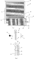
- a waveguide apparatus 40 includes a substrate of material 42 having first and second layers 44 and 46 arranged within the substrate of material 42 so as to define separate first, second and third channels 48, 50 and 52.
- the first and second layers can be formed from a thin film dielectric coating.
- the channels, 48, 50, 52 are arranged to transmit light in respective predefined wavelengths or wavelength ranges within the channel 48, 50, 52 under total internal reflection.
- the first channel 48 is arranged to transmit light in a first wavelength range and in this example, the first channel transmits light in a red wavelength range of image bearing light R (e.g. in the range between about 590 to 750 nm).
- the second channel 50 is arranged to transmit light in a second wavelength range and in this example, the second channel transmits light in a green wavelength range of image bearing light G (e.g. in the range between about 495 and 590 nm).
- the third channel 52 is arranged to transmit light in a third predetermined wavelength range and in this example, the third channel transmits light in a blue wavelength range of image bearing light B (e.g. in the range between about 380 and 495 nm).
- each channel 48, 50, 52 has a grating 54, 56, 58 within the channel 48, 50, 52 that is arranged to diffract a portion of image bearing light incident thereon out of the substrate of material 42 and to allow the remainder of the image bearing light incident thereon to be transmitted in its respective channel 48, 50, 52 under total internal reflection.
- Image bearing light passing through the grating 54, 56, 58 continues along a light path 60, 62, 64 towards a distal end 66 of the substrate of material 42 to further interact with the grating 54, 56, 58 associate with the channel 48, 50, 52.
- the image bearing light interacts with the grating 54, such that a portion R1, R2, R3, R4 is diffracted out of the substrate of material 42 upon each interaction.
- the image bearing light interacts with the grating 56, such that a portion G1, G2, G3, G4 is diffracted out of the substrate of material 42 upon each interaction.
- the blue wavelengths of image bearing light B follow the light path 64 under total internal reflection between the second layer 46 and second face 70 of the substrate of material 42.
- the image bearing light interacts with the grating 58, such that a portion B1, B2, B3, B4 is diffracted out of the substrate of material 42 upon each interaction.
- a number of pupils of image bearing light 72, 74, 76, 78 are formed by the red, green and blue outputs from the substrate of material 42, that is pupil 72 is formed from R1, G1 and B1, pupil 74 is formed from R2, G2 and B2, pupil 76 is formed from R3, G3 and B3 and pupil 78 is formed from R4, G4 and B4.
- the pupils of image bearing light 72, 74, 76, 78 when viewed by an observer, not shown, will convey an image to the observer. It will be appreciated that the arrangement provides a single combiner in the form of the substrate for the image bearing light in separate wavelengths.
- image bearing light is injected into the substrate of material 42 via separate optical elements for each channel 48, 50, 52. That is, the red, green and blue wavelengths of image bearing light R, G, B, are separated prior to injection into the appropriate channel 48, 50, 52 of the substrate of material 42.
- the red, green and blue wavelengths may be within relatively narrow ranges and selected in order to reproduce an image of the required colour in the final viewed image.
- the red wavelengths of image bearing light R enter the first channel 48 via a reflective element 80 and follow light path 60 between first face 68 of the substrate of material 42 and the first layer 44.
- the green wavelengths of image bearing light G enter the second channel 50 via a reflective element 82 and follow light path 62 between first layer 44 and second layer 46.
- the blue wavelengths of image bearing light B enter the third channel 52 via a reflective element 84 and follow light path 64 between the second layer 46 and the second face 70 of the substrate of material 42.
- an apparatus 90 to separate an image to be conveyed to an observer, not shown, into red, green and blue wavelengths of image bearing light A suitable image-providing light source device 92 is arranged to inject image bearing light into the apparatus 90.
- the image bearing light is split or filtered to provide a red channel R by a first optical element 94.
- the image bearing light associated with the red channel R is then reflected by a suitable mirror 96 to allow injection into the waveguide apparatus, for example 40 of Figure 4 .
- the green and blue components of the image bearing light pass through the first optical element 94 and is split or filtered to provide separate green and blue channels G, B by a second optical element 98.
- the image bearing light associated with the green channel G passes through the second optical element 98 and the image bearing light associated with the blue channel B is reflected by a suitable mirror 100 to allow injection into the waveguide apparatus 40.
- image bearing light is injected into the substrate of material 42 via a single point.
- the red, green and blue wavelengths of image bearing light are separated by optical elements associated with each channel as the image bearing light passes into the channel 48, 50, 52.
- the red, green and blue wavelengths of image bearing light R, G, B enter the first channel 48 and are filtered or split by a first optical element 102 such that the green and blue wavelengths of image bearing light G, B pass through the first optical element 102 into the second channel 50, whilst the red wavelengths of image bearing light R follow light path 60 between first face 68 of the substrate of material 42 and the first layer 44.
- the green and blue wavelengths of image bearing light G,B enter the second channel 50 and are filtered or split by a second optical element 104 such that the blue wavelengths of image bearing light B pass through the second optical element 104 into the third channel 52, whilst the green wavelengths of image bearing light G follow light path 62 between first layer 44 and second layer 46.
- the blue wavelengths of image bearing light B enter the third channel 52 and are reflected by a third optical element 106 such that the blue wavelengths of image bearing light B follow light path 64 between the second layer 46 and the second face 70 of the substrate of material 42.
- the injection of image bearing light into a waveguide element 40 can be via one or more reflective, transmissive or refractive optical elements.
- the grating elements 54, 56, 58 can be reflective, thereby being arranged on or near an internal surface of a channel 48, 50, 52 or transmissive, thereby being arranged towards the centre of the channel 48, 50, 52.
- a substrate of material 42 having three channels 48, 50, 52 can have a crosstalk component associated with each of the wavelengths of image bearing light required to pass through a channel 48, 50, 52 and its associated grating 54, 56, 58 which is arranged to transmit another wavelength of image bearing light.
- blue wavelengths of image bearing light B OUT will have to cross second channel 50, its associated grating 56, first channel 48 and its associated grating 54 to exit the substrate of material 42.
- the green wavelengths of image bearing light G will have to cross the first channel 48 and its associated grating 54 to exit the substrate of material 42.
- Crosstalk can be caused by unwanted interaction of image bearing with the grating 54, 56, 58 of another channel 48, 50, 52.
- the grating 58 is arranged to diffract seven percent (7%) of incident image bearing light out of the channel 52, as indicated by reference B OUT , and five percent (5%) of image bearing light diffracted out of the channel 52 couples into an adjacent channel 48, 50 due to crosstalk, as indicated by the references B R and B G , then only five percent of seven percent (0.35%) of the blue wavelengths of image bearing light will couple into either the red or green channels 48, 50. This small amount of crosstalk should not affect the performance of the waveguide apparatus 40 and can be ignored.
- a grating 54, 56, 58 can be optimised such that if image bearing light from another channel is coupled into a channel 48, 50, 52, then the grating 54, 56, 58 will diffract light from another channel off axis to the primary axis of the waveguide apparatus 40, as indicated by reference B OUT .
- the blue wavelengths of image bearing light B if the gratings 54 and 56 of the first and second channels 48 and 50 are arranged to diffract blue wavelengths of image bearing light B off axis to the primary axis B OUT of the waveguide apparatus 40, as indicated by the references B R and B G , then an observer, not shown, will not perceive such off axis blue wavelengths of image bearing light B R and B G .
- a projection display 210 for displaying an image to an observer 212 that uses waveguide techniques to generate a display defining a large exit pupil at the point of the observer 212 and a large field of view, whilst using a small image-providing light source device.
- the projection display 210 uses a first plate-like waveguide 214 made of light transmissive material such as glass or plastic and a second plate-like waveguide 216 made from a light transmissive and light transparent material such as glass or plastic.
- the projection display 210 additionally includes an image-providing light source device, not shown, located to inject image bearing light into the first plate-like waveguide 214 through a first face 218.
- the image-providing light source device includes a micro-display arranged to provide information to be displayed to the observer 212. Additionally the image-providing light source device may include a collimating optical arrangement located between the micro-display and the first face 218 of the first plate-like waveguide 214. If used, the collimating optical arrangement is operable to collimate light received from the micro-display and to inject the collimated image bearing light into the first plate-like waveguide 214 through the first face 218.
- Image bearing light produced by the image-providing light source device has a small exit pupil and is fed into the first plate-like waveguide 214, which performs the function of stretching the horizontal pupil of the final display.
- the output from the first plate-like waveguide 214 is fed into the second plate-like waveguide 216, which is arranged to stretch the vertical pupil of the final display and also to act as a combiner for the projection display 210 through which the observer 212 views an outside world scene 220 along a line of sight 222 of the observer 212 through the second plate-like waveguide 216 with information to be displayed to the observer 212 overlaid on the outside world scene 220.
- the image to be displayed to the observer 12 looking through the second plate-like waveguide 216 defines a large exit pupil and a large field of view whilst using a small image generating light source.
- the image bearing light is comprised of three wavelengths, red, green and blue and each of these wavelengths is substantially isolated from one another throughout its passage through the projection display 210 in individual channels as indicated by referenced R, G and B.
- Image bearing light injected into the first plate-like waveguide 214, via first face 218 is incident on one of three first grating 224R, 224G, 224B, each arranged internally within the first plate-like waveguide 214 and substantially parallel with the first face 218 and one each associated with an individual channel R, G, B.
- first gratings 224R, 224G, 224B diffracts therefrom such that the incidence angle of the light on the internal surfaces of channel R, G, B is greater than the critical angle for the material from which the channel R, G, B is formed.
- the image bearing light is constrained within the channel R, G, B to propagate along the first plate-like waveguide 214 reflecting from each internal surface in turn to follow a predefined light path 226R, 226G, 226B.
- the relative field angles of the light incident on the first plate-like waveguide 214 at the first face 218 are preserved within each channel R, G, B and the information required to regenerate the original image is preserved.
- the first gratings 224R, 224G, 224B also serve to radiate the image bearing light out of the first plate-like waveguide 214.
- Each first grating 224 is a low efficiency grating which diffracts a small amount of light out of the first plate-like waveguide 214 on each interaction with incident image bearing light.
- the second plate-like waveguide 216 is located with a first face 228 parallel with a second face 230 of the first plate-like waveguide 214 and is arranged to receive the image bearing light exiting the second face 230 from each channel R, G, B of the first plate-like waveguide 214.
- the second face 230 is parallel to the first face 218 of the first plate-like waveguide 214.
- the first face 228 of the second plate-like waveguide 216 is located adjacent and close to the second face 230 of the first plate-like waveguide 214.
- the second plate-like waveguide 216 includes separate channels R, G, B each having a second grating 232R, 232G, 232B located therein arranged substantially parallel to the first face 228 of the second plate-like waveguide 216 and each second grating 232R, 232G, 232B is operable to diffract impinging image bearing light received from an associated first grating 224R, 224G, 224B of the first plate-like waveguide 214 at an angle that is larger than the critical angle for the material from which the channel R, G, B is formed. Accordingly, received image bearing light will propagate inside one of the channels R, G, B of the second plate-like waveguide 216 to follow the predefined light path 226R, 226G, 226B.
- the image bearing light continues along the light path 226R, 226G, 226B to a third grating 234R, 234G, 234B arranged within each channel R, G, B of the second plate-like waveguide 216 which is arranged to diffract the received image bearing light out of the second plate-like waveguide 216 towards the observer 212.
- Each second grating 232R, 232G, 232B is arranged such that its diffractive power is rotated through 90 degrees to that of the diffractive power of its associated parallel first grating 224R, 224G, 224B to rotate incident image bearing light towards its associated third grating 234R, 234G, 234B.
- Each third grating 234R, 234G, 234B is a low efficiency grating, such that as image bearing light propagates along a light path 226R, 226G, 226B within a channel R, G, B of the second plate-like waveguide 216, each interaction with the third grating 234R, 234G, 234B causes a small proportion of the image bearing light to be diffracted out of the second plate-like waveguide 216. Image bearing light which is not diffracted out of the second plate-like waveguide 216 continues to propagate within its channel R, G, B within the second plate-like waveguide 216.
- a large number of parallel rays of image bearing light exit the second plate-like waveguide 216 via one of the third gratings 234R, 234G, 234B towards the observer 212, which originated at discrete points on the micro-display forming the image generating light source device.
- the correct image to be conveyed to the observer 212 is presented for viewing when the observer 212 views an outside world scene 220 through the second plate-like waveguide 216.
Claims (13)
- Wellenleitervorrichtung, umfassend:ein einziges Substrat aus lichtdurchlässigem Material;mindestens eine Schicht, die innerhalb des Materialsubstrats angeordnet ist, wobei die Schicht so angeordnet ist, dass sie getrennte Kanäle innerhalb des Materialsubstrats definiert, wobei jeder Kanal so angeordnet ist, dass er Licht einer verschiedenen vordefinierten Wellenlänge zum anderen Kanal oder zu den anderen Kanälen gemäß interner Totalreflexion überträgt;ein Gitter, das mit jedem Kanal assoziiert ist, wobei jedes Gitter so angeordnet ist, dass es einen Teil von darauf auftreffendem Licht aus dem Materialsubstrat ablenkt und den Rest des darauf auffallendem Licht in seinem assoziierten Kanal gemäß interner Totalreflexion überträgt; undwobei Licht vor der Einkopplung in das Materialsubstrat unabhängig von der Wellenlänge getrennt wird.
- Wellenleitervorrichtung nach Anspruch 1, wobei zwei Schichten so innerhalb des Materialsubstrats angeordnet sind, dass sie drei getrennte Kanäle definieren, und wobei ein erster Kanal zum Übertragen von Licht in einer Rot-Wellenlänge angeordnet ist, ein zweiter Kanal zum Übertragen von Licht in einem Grün-Wellenlängenbereich angeordnet ist, und ein dritter Kanal zum Übertragen der Blau-Wellenlänge von Licht angeordnet ist.
- Wellenleitervorrichtung nach einem der vorhergehenden Ansprüche, wobei mindestens ein Filter zum Trennen von Licht in Abhängigkeit von der Wellenlänge vor der Übertragung innerhalb eines Kanals angeordnet ist.
- Wellenleitervorrichtung nach Anspruch 3, wobei mindestens ein Filter auf oder innerhalb des Materialsubstrats getragen wird.
- Wellenleitervorrichtung nach einem der vorhergehenden Ansprüche, wobei jedes Gitter zum Ablenken von Licht aus dem Materialsubstrat angeordnet ist, wobei das Licht im Wesentlichen parallel zu Licht ist, das durch jedes andere Gitter innerhalb eines anderen Kanals aus dem Materialsubstrat abgelenkt wird.
- Wellenleitervorrichtung nach einem der vorhergehenden Ansprüche, wobei die Kanäle jeweilige optische Elemente zum Einkoppeln von bildtragendem Licht in die Kanäle aufweisen, wobei die optischen Elemente so ausgelegt sind, dass sie nur bildtragendes Licht innerhalb jeweiliger der vordefinierten Wellenlängen in die Kanäle einkoppeln und bildtragendes Licht außerhalb dieser jeweiligen vordefinierten Wellenlängen dadurch durchlassen.
- Wellenleitervorrichtung nach einem der vorhergehenden Ansprüche, wobei das Gitter ein holographisch-optisches Element ist.
- Projektionsanzeige zum Anzeigen eines Bildes für einen Betrachter, umfassend:ein erstes Wellenleiterelement, das so angeordnet ist, dass es lichtdurchlässig ist;eine bildbereitstellende Lichtquellenvorrichtung, die zum Erzeugen eines Bildes und Einkoppeln von bildtragendem Licht in das erste Wellenleiterelement angeordnet ist;wobei das erste Wellenleiterelement so angeordnet ist, dass es das bildtragende Licht intern entlang des ersten Wellenleiterelements leitet, und durch welches das bildtragende Licht aus dem ersten Wellenleiterelement ausgegeben wird;ein zweites Wellenleiterelement, das so angeordnet ist, dass es lichtdurchlässig und transparent ist, und so angeordnet ist, dass es das bildtragende Licht vom ersten Wellenleiterelement empfängt und das bildtragende Licht entlang des zweiten Wellenleiterelements leitet;wobei das zweite Welleneiterelement ferner so angeordnet ist, dass es bildtragendes Licht aus dem zweiten Wellenleiterelement an einen Betrachter ausgibt; undwobei das erste Wellenleiterelement nach Anspruch 1 ist;wobei das zweite Wellenleiterelement ein einziges Materialsubstrat mit mindestens einer Schicht, die innerhalb des Materialsubstrats angeordnet ist, wobei die Schicht so angeordnet ist, dass sie getrennte Kanäle innerhalb des Materialsubstrats definiert, wobei jeder Kanal so angeordnet ist, dass er Licht einer verschiedenen vordefinierten Wellenlänge zum anderen Kanal oder zu den anderen Kanälen gemäß interner Totalreflexion überträgt, und ein zweites Gitter umfasst, das mit jedem Kanal assoziiert ist, wobei jedes zweite Gitter so angeordnet ist, dass es darauf auftreffendes Licht ablenkt, um in seinem assoziierten Kanal gemäß interner Totalreflexion übertragen zu werden; undwobei das zweite Wellenleiterelement außerdem ein drittes Gitter umfasst, das mit jedem Kanal assoziiert ist, wobei jedes Gitter so angeordnet ist, dass es einen Teil von darauf auftreffendem Licht aus dem Materialsubstrat zum Betrachter ablenkt und den Rest des darauf auffallenden Lichts in seinem assoziierten Kanal gemäß interner Totalreflexion überträgt.
- Projektionsanzeige nach Anspruch 8, wobei das erste Wellenleiterelement plattenförmig ist, das zweite Wellenleiterelement plattenförmig ist, und das erste und das zweite Wellenleiterelement im Wesentlichen parallel zueinander angeordnet sind.
- Projektionsanzeige nach Anspruch 8, wobei das erste Wellenleiterelement und das zweite Wellenleiterelement im Wesentlichen in derselben Ebene angeordnet sind.
- Projektionsanzeige nach Anspruch 8, wobei das erste Wellenleiterelement stäbchenförmig ist, das zweite Wellenleiterelement plattenförmig ist, und das erste und das zweite Wellenleiterelement derart angeordnet sind, dass das bildtragende Licht aus dem ersten Wellenleiterelement entlang einer Längsachse des ersten Wellenleiterelements austritt und in das zweite Wellenleiterelement eintritt, um sich entlang einer Ausbreitungsachse des zweiten Wellenleiterelements auszubreiten.
- Blickfeldanzeige oder helmmontierte Anzeige oder kopfmontierte Anzeige, umfassend eine Projektionsanzeige nach einem der Ansprüche 8 bis 11.
- Blickfeldanzeige oder helmmontierte Anzeige oder kopfmontierte Anzeige, umfassend eine Wellenleitervorrichtung nach einem der Ansprüche 1 bis 7.
Priority Applications (1)
| Application Number | Priority Date | Filing Date | Title |
|---|---|---|---|
| EP09768226.4A EP2373924B2 (de) | 2008-12-12 | 2009-12-09 | Verbesserungen an oder im zusammenhang mit wellenleitern |
Applications Claiming Priority (4)
| Application Number | Priority Date | Filing Date | Title |
|---|---|---|---|
| GB0822685A GB0822685D0 (en) | 2008-12-12 | 2008-12-12 | Improvements in or relating to waveguides |
| EP08275084A EP2196729A1 (de) | 2008-12-12 | 2008-12-12 | Verbesserungen an oder im Zusammenhang mit Wellenleitern |
| EP09768226.4A EP2373924B2 (de) | 2008-12-12 | 2009-12-09 | Verbesserungen an oder im zusammenhang mit wellenleitern |
| PCT/GB2009/051676 WO2010067114A1 (en) | 2008-12-12 | 2009-12-09 | Improvements in or relating to waveguides |
Publications (3)
| Publication Number | Publication Date |
|---|---|
| EP2373924A1 EP2373924A1 (de) | 2011-10-12 |
| EP2373924B1 EP2373924B1 (de) | 2019-02-20 |
| EP2373924B2 true EP2373924B2 (de) | 2022-01-05 |
Family
ID=42116037
Family Applications (1)
| Application Number | Title | Priority Date | Filing Date |
|---|---|---|---|
| EP09768226.4A Active EP2373924B2 (de) | 2008-12-12 | 2009-12-09 | Verbesserungen an oder im zusammenhang mit wellenleitern |
Country Status (4)
| Country | Link |
|---|---|
| US (1) | US8965152B2 (de) |
| EP (1) | EP2373924B2 (de) |
| ES (1) | ES2721600T5 (de) |
| WO (1) | WO2010067114A1 (de) |
Families Citing this family (164)
| Publication number | Priority date | Publication date | Assignee | Title |
|---|---|---|---|---|
| US10073264B2 (en) | 2007-08-03 | 2018-09-11 | Lumus Ltd. | Substrate-guide optical device |
| US10048499B2 (en) | 2005-11-08 | 2018-08-14 | Lumus Ltd. | Polarizing optical system |
| GB0522968D0 (en) | 2005-11-11 | 2005-12-21 | Popovich Milan M | Holographic illumination device |
| GB0718706D0 (en) | 2007-09-25 | 2007-11-07 | Creative Physics Ltd | Method and apparatus for reducing laser speckle |
| US11726332B2 (en) | 2009-04-27 | 2023-08-15 | Digilens Inc. | Diffractive projection apparatus |
| US9335604B2 (en) | 2013-12-11 | 2016-05-10 | Milan Momcilo Popovich | Holographic waveguide display |
| US11300795B1 (en) | 2009-09-30 | 2022-04-12 | Digilens Inc. | Systems for and methods of using fold gratings coordinated with output couplers for dual axis expansion |
| US11320571B2 (en) * | 2012-11-16 | 2022-05-03 | Rockwell Collins, Inc. | Transparent waveguide display providing upper and lower fields of view with uniform light extraction |
| US8233204B1 (en) | 2009-09-30 | 2012-07-31 | Rockwell Collins, Inc. | Optical displays |
| US10795160B1 (en) | 2014-09-25 | 2020-10-06 | Rockwell Collins, Inc. | Systems for and methods of using fold gratings for dual axis expansion |
| US11204540B2 (en) | 2009-10-09 | 2021-12-21 | Digilens Inc. | Diffractive waveguide providing a retinal image |
| US20200057353A1 (en) | 2009-10-09 | 2020-02-20 | Digilens Inc. | Compact Edge Illuminated Diffractive Display |
| US8659826B1 (en) | 2010-02-04 | 2014-02-25 | Rockwell Collins, Inc. | Worn display system and method without requiring real time tracking for boresight precision |
| EP2444834A1 (de) * | 2010-10-19 | 2012-04-25 | Bae Systems Plc | Bildkombinierer |
| ES2804475T3 (es) * | 2010-10-19 | 2021-02-08 | Bae Systems Plc | Dispositivo de visualización que comprende un combinador de imágenes |
| WO2012136970A1 (en) | 2011-04-07 | 2012-10-11 | Milan Momcilo Popovich | Laser despeckler based on angular diversity |
| GB201114149D0 (en) * | 2011-08-17 | 2011-10-05 | Bae Systems Plc | Projection display |
| EP2995986B1 (de) | 2011-08-24 | 2017-04-12 | Rockwell Collins, Inc. | Datenanzeige |
| US10670876B2 (en) | 2011-08-24 | 2020-06-02 | Digilens Inc. | Waveguide laser illuminator incorporating a despeckler |
| WO2016020630A2 (en) | 2014-08-08 | 2016-02-11 | Milan Momcilo Popovich | Waveguide laser illuminator incorporating a despeckler |
| US9715067B1 (en) | 2011-09-30 | 2017-07-25 | Rockwell Collins, Inc. | Ultra-compact HUD utilizing waveguide pupil expander with surface relief gratings in high refractive index materials |
| US8634139B1 (en) | 2011-09-30 | 2014-01-21 | Rockwell Collins, Inc. | System for and method of catadioptric collimation in a compact head up display (HUD) |
| US9366864B1 (en) | 2011-09-30 | 2016-06-14 | Rockwell Collins, Inc. | System for and method of displaying information without need for a combiner alignment detector |
| US9599813B1 (en) | 2011-09-30 | 2017-03-21 | Rockwell Collins, Inc. | Waveguide combiner system and method with less susceptibility to glare |
| US20150010265A1 (en) | 2012-01-06 | 2015-01-08 | Milan, Momcilo POPOVICH | Contact image sensor using switchable bragg gratings |
| US9523852B1 (en) | 2012-03-28 | 2016-12-20 | Rockwell Collins, Inc. | Micro collimator system and method for a head up display (HUD) |
| WO2013163347A1 (en) | 2012-04-25 | 2013-10-31 | Rockwell Collins, Inc. | Holographic wide angle display |
| US9456744B2 (en) | 2012-05-11 | 2016-10-04 | Digilens, Inc. | Apparatus for eye tracking |
| US9933684B2 (en) * | 2012-11-16 | 2018-04-03 | Rockwell Collins, Inc. | Transparent waveguide display providing upper and lower fields of view having a specific light output aperture configuration |
| JP6847901B2 (ja) * | 2012-11-16 | 2021-03-24 | ロックウェル・コリンズ・インコーポレーテッド | 透明導波路ディスプレイ |
| US9674413B1 (en) | 2013-04-17 | 2017-06-06 | Rockwell Collins, Inc. | Vision system and method having improved performance and solar mitigation |
| US10209517B2 (en) | 2013-05-20 | 2019-02-19 | Digilens, Inc. | Holographic waveguide eye tracker |
| US10533850B2 (en) | 2013-07-12 | 2020-01-14 | Magic Leap, Inc. | Method and system for inserting recognized object data into a virtual world |
| US9727772B2 (en) | 2013-07-31 | 2017-08-08 | Digilens, Inc. | Method and apparatus for contact image sensing |
| US9244281B1 (en) | 2013-09-26 | 2016-01-26 | Rockwell Collins, Inc. | Display system and method using a detached combiner |
| JP6287095B2 (ja) * | 2013-11-19 | 2018-03-07 | セイコーエプソン株式会社 | 光学デバイス及び電子機器 |
| US11402629B2 (en) * | 2013-11-27 | 2022-08-02 | Magic Leap, Inc. | Separated pupil optical systems for virtual and augmented reality and methods for displaying images using same |
| NZ720610A (en) * | 2013-11-27 | 2020-04-24 | Magic Leap Inc | Virtual and augmented reality systems and methods |
| EP2887128B1 (de) * | 2013-12-18 | 2021-10-27 | Microsoft Technology Licensing, LLC | NED-Polarisationssystem für Wellenlängendurchgang |
| US10732407B1 (en) | 2014-01-10 | 2020-08-04 | Rockwell Collins, Inc. | Near eye head up display system and method with fixed combiner |
| US9519089B1 (en) | 2014-01-30 | 2016-12-13 | Rockwell Collins, Inc. | High performance volume phase gratings |
| US9244280B1 (en) | 2014-03-25 | 2016-01-26 | Rockwell Collins, Inc. | Near eye display system and method for display enhancement or redundancy |
| JP6413291B2 (ja) * | 2014-03-27 | 2018-10-31 | セイコーエプソン株式会社 | 虚像表示装置、およびヘッドマウントディスプレイ |
| IL232197B (en) | 2014-04-23 | 2018-04-30 | Lumus Ltd | Compact head-up display system |
| US10359736B2 (en) | 2014-08-08 | 2019-07-23 | Digilens Inc. | Method for holographic mastering and replication |
| WO2016042283A1 (en) | 2014-09-19 | 2016-03-24 | Milan Momcilo Popovich | Method and apparatus for generating input images for holographic waveguide displays |
| US9715110B1 (en) | 2014-09-25 | 2017-07-25 | Rockwell Collins, Inc. | Automotive head up display (HUD) |
| US10088675B1 (en) | 2015-05-18 | 2018-10-02 | Rockwell Collins, Inc. | Turning light pipe for a pupil expansion system and method |
| EP3198192A1 (de) | 2014-09-26 | 2017-08-02 | Milan Momcilo Popovich | Optischer tracker mit holografischem wellenleiter |
| KR20240005987A (ko) | 2014-09-29 | 2024-01-12 | 매직 립, 인코포레이티드 | 상이한 파장의 광을 도파관 밖으로 출력하기 위한 아키텍쳐 및 방법 |
| JP2016085430A (ja) * | 2014-10-29 | 2016-05-19 | セイコーエプソン株式会社 | 虚像表示装置 |
| IL235642B (en) | 2014-11-11 | 2021-08-31 | Lumus Ltd | A compact head-up display system is protected by an element with a super-thin structure |
| WO2016076153A1 (ja) * | 2014-11-11 | 2016-05-19 | シャープ株式会社 | 導光板および虚像表示装置 |
| EP3245444B1 (de) | 2015-01-12 | 2021-09-08 | DigiLens Inc. | Umweltisolierte wellenleiteranzeige |
| EP3245551B1 (de) | 2015-01-12 | 2019-09-18 | DigiLens Inc. | Lichtfeldanzeigen mit wellenleiter |
| GB201500693D0 (en) * | 2015-01-16 | 2015-03-04 | Wave Optics Ltd | Display System |
| JP6867947B2 (ja) | 2015-01-20 | 2021-05-12 | ディジレンズ インコーポレイテッド | ホログラフィック導波路ライダー |
| US9632226B2 (en) | 2015-02-12 | 2017-04-25 | Digilens Inc. | Waveguide grating device |
| IL237337B (en) * | 2015-02-19 | 2020-03-31 | Amitai Yaakov | A compact head-up display system with a uniform image |
| US20160266304A1 (en) * | 2015-03-09 | 2016-09-15 | National Taiwan Normal University | Light-guiding device and system thereof for receiving the light sources of different angular distribution and emitting the spatially uniform light in the corresponding direction |
| US10459145B2 (en) | 2015-03-16 | 2019-10-29 | Digilens Inc. | Waveguide device incorporating a light pipe |
| NZ773845A (en) | 2015-03-16 | 2022-07-01 | Magic Leap Inc | Methods and systems for diagnosing and treating health ailments |
| WO2016156776A1 (en) | 2015-03-31 | 2016-10-06 | Milan Momcilo Popovich | Method and apparatus for contact image sensing |
| JP6820107B2 (ja) * | 2015-05-04 | 2021-01-27 | マジック リープ, インコーポレイテッドMagic Leap,Inc. | 仮想および拡張現実のための分離された瞳光学システムおよびそれを用いた画像表示の方法 |
| US10247943B1 (en) | 2015-05-18 | 2019-04-02 | Rockwell Collins, Inc. | Head up display (HUD) using a light pipe |
| US11366316B2 (en) | 2015-05-18 | 2022-06-21 | Rockwell Collins, Inc. | Head up display (HUD) using a light pipe |
| US10126552B2 (en) | 2015-05-18 | 2018-11-13 | Rockwell Collins, Inc. | Micro collimator system and method for a head up display (HUD) |
| CA2984138A1 (en) * | 2015-05-28 | 2016-12-01 | Thalmic Labs Inc. | Systems, devices, and methods that integrate eye tracking and scanning laser projection in wearable heads-up displays |
| EP4249965A3 (de) | 2015-06-15 | 2023-12-27 | Magic Leap, Inc. | Anzeigesystem mit optischen elementen zur einkopplung von multiplexing-lichtströmen |
| US10108010B2 (en) | 2015-06-29 | 2018-10-23 | Rockwell Collins, Inc. | System for and method of integrating head up displays and head down displays |
| US9904057B2 (en) | 2015-08-31 | 2018-02-27 | Seiko Epson Corporation | Light guide device and virtual image display apparatus |
| JP6598269B2 (ja) | 2015-10-05 | 2019-10-30 | ディジレンズ インコーポレイテッド | 導波管ディスプレイ |
| US10598932B1 (en) | 2016-01-06 | 2020-03-24 | Rockwell Collins, Inc. | Head up display for integrating views of conformally mapped symbols and a fixed image source |
| CN109073889B (zh) | 2016-02-04 | 2021-04-27 | 迪吉伦斯公司 | 全息波导光学跟踪器 |
| US10473933B2 (en) * | 2016-02-19 | 2019-11-12 | Microsoft Technology Licensing, Llc | Waveguide pupil relay |
| WO2017147527A1 (en) * | 2016-02-24 | 2017-08-31 | Magic Leap, Inc. | Polarizing beam splitter with low light leakage |
| EP3420389B1 (de) * | 2016-02-26 | 2021-06-23 | Magic Leap, Inc. | Anzeigesystem mit einer vielzahl an lichtröhren für eine vielzahl von lichtsendern |
| KR20180115795A (ko) * | 2016-02-29 | 2018-10-23 | 매직 립, 인코포레이티드 | 가상 및 증강 현실 시스템들 및 방법들 |
| NZ757279A (en) * | 2016-03-01 | 2022-10-28 | Magic Leap Inc | Reflective switching device for inputting different wavelengths of light into waveguides |
| CN109074785B (zh) | 2016-03-04 | 2022-05-10 | 奇跃公司 | 减少用电的显示系统以及用于减少显示系统的用电的方法 |
| GB2548577A (en) * | 2016-03-21 | 2017-09-27 | Promethean Ltd | Interactive system |
| CN108780224B (zh) | 2016-03-24 | 2021-08-03 | 迪吉伦斯公司 | 用于提供偏振选择性全息波导装置的方法和设备 |
| KR20180122726A (ko) * | 2016-03-25 | 2018-11-13 | 매직 립, 인코포레이티드 | 가상 및 증강 현실 시스템들 및 방법들 |
| KR20220040511A (ko) | 2016-04-08 | 2022-03-30 | 매직 립, 인코포레이티드 | 가변 포커스 렌즈 엘리먼트들을 가진 증강 현실 시스템들 및 방법들 |
| US10890707B2 (en) | 2016-04-11 | 2021-01-12 | Digilens Inc. | Holographic waveguide apparatus for structured light projection |
| KR102641964B1 (ko) | 2016-05-12 | 2024-02-27 | 매직 립, 인코포레이티드 | 이미징 도파관을 통해 분배된 광 조작 |
| CN106125316B (zh) * | 2016-06-24 | 2018-09-11 | 西安电子科技大学 | 基于光栅波导的节能无跳转图像集成成像显示装置 |
| US10663756B2 (en) * | 2016-07-18 | 2020-05-26 | Lumens Co., Ltd. | Display apparatus |
| US10267970B2 (en) * | 2016-08-22 | 2019-04-23 | Magic Leap, Inc. | Thermal dissipation for wearable device |
| CN113156647B (zh) | 2016-10-09 | 2023-05-23 | 鲁姆斯有限公司 | 光学装置 |
| MX2018007164A (es) | 2016-11-08 | 2019-06-06 | Lumus Ltd | Dispositivo de guia de luz con borde de corte optico y metodos de produccion correspondientes. |
| US11067860B2 (en) | 2016-11-18 | 2021-07-20 | Magic Leap, Inc. | Liquid crystal diffractive devices with nano-scale pattern and methods of manufacturing the same |
| KR102639600B1 (ko) | 2016-11-18 | 2024-02-21 | 매직 립, 인코포레이티드 | 넓은 입사 각도 범위들의 광을 방향전환시키기 위한 다중층 액정 회절 격자들 |
| US11378864B2 (en) | 2016-11-18 | 2022-07-05 | Magic Leap, Inc. | Waveguide light multiplexer using crossed gratings |
| JP7116058B2 (ja) | 2016-11-18 | 2022-08-09 | マジック リープ, インコーポレイテッド | 空間可変液晶回折格子 |
| GB2556938B (en) | 2016-11-28 | 2022-09-07 | Bae Systems Plc | Multiple waveguide structure for colour displays |
| WO2018102834A2 (en) | 2016-12-02 | 2018-06-07 | Digilens, Inc. | Waveguide device with uniform output illumination |
| KR102585679B1 (ko) | 2016-12-08 | 2023-10-05 | 매직 립, 인코포레이티드 | 콜레스테릭 액정에 기초한 회절 디바이스들 |
| US10895784B2 (en) | 2016-12-14 | 2021-01-19 | Magic Leap, Inc. | Patterning of liquid crystals using soft-imprint replication of surface alignment patterns |
| US10371896B2 (en) * | 2016-12-22 | 2019-08-06 | Magic Leap, Inc. | Color separation in planar waveguides using dichroic filters |
| CN106646885B (zh) * | 2016-12-30 | 2020-02-11 | 苏州苏大维格光电科技股份有限公司 | 一种投影物镜及三维显示装置 |
| WO2018129398A1 (en) | 2017-01-05 | 2018-07-12 | Digilens, Inc. | Wearable heads up displays |
| CN110462460B (zh) | 2017-01-23 | 2022-10-14 | 奇跃公司 | 用于虚拟、增强或混合现实系统的目镜 |
| KR20190105576A (ko) * | 2017-01-26 | 2019-09-17 | 디지렌즈 인코포레이티드 | 균일한 출력 조명을 갖는 도파관 장치 |
| US10295824B2 (en) | 2017-01-26 | 2019-05-21 | Rockwell Collins, Inc. | Head up display with an angled light pipe |
| CN110431467A (zh) | 2017-01-28 | 2019-11-08 | 鲁姆斯有限公司 | 增强现实成像系统 |
| US11460694B2 (en) * | 2017-02-14 | 2022-10-04 | Snap Inc. | Waveguide structure |
| US10955668B2 (en) * | 2017-02-14 | 2021-03-23 | Optecks, Llc | Optical display system for augmented reality and virtual reality |
| EP3583461A4 (de) * | 2017-02-15 | 2020-03-04 | Magic Leap, Inc. | Projektorarchitektur mit artefaktminderung |
| CN108445573B (zh) * | 2017-02-16 | 2023-06-30 | 中强光电股份有限公司 | 光波导元件以及显示装置 |
| KR102338472B1 (ko) | 2017-02-22 | 2021-12-14 | 루머스 리미티드 | 광 가이드 광학 어셈블리 |
| KR102601052B1 (ko) | 2017-02-23 | 2023-11-09 | 매직 립, 인코포레이티드 | 가변 파워 반사기를 갖는 디스플레이 시스템 |
| CN110651211B (zh) * | 2017-03-21 | 2022-08-05 | 奇跃公司 | 具有用于分体式光瞳的空间光调制器照射的显示系统 |
| AU2018239264B2 (en) | 2017-03-21 | 2023-05-18 | Magic Leap, Inc. | Eye-imaging apparatus using diffractive optical elements |
| JP6956414B2 (ja) | 2017-03-22 | 2021-11-02 | ルムス エルティーディー. | 重複ファセット |
| EP3607244B1 (de) * | 2017-04-04 | 2023-12-13 | LEIA Inc. | Mehrschichtige mehrfachansichtsanzeige und verfahren |
| IL251645B (en) | 2017-04-06 | 2018-08-30 | Lumus Ltd | Waveguide and method of production |
| US10930710B2 (en) * | 2017-05-04 | 2021-02-23 | Apple Inc. | Display with nanostructure angle-of-view adjustment structures |
| US10527852B2 (en) | 2017-05-24 | 2020-01-07 | Microsoft Technology Licensing, Llc | Diffractive filtering in a waveguide display |
| WO2019060741A1 (en) | 2017-09-21 | 2019-03-28 | Magic Leap, Inc. | INCREASED REALITY DISPLAY HAVING A WAVEGUIDE CONFIGURED TO CAPTURE IMAGES OF THE EYE AND / OR THE ENVIRONMENT |
| MX2020003919A (es) * | 2017-09-29 | 2020-08-10 | Corning Res & Dev Corp | Conectores de fibra optica y montaje de cables conexionados con guarniciones de quiebre en voladizo. |
| WO2019079350A2 (en) | 2017-10-16 | 2019-04-25 | Digilens, Inc. | SYSTEMS AND METHODS FOR MULTIPLYING THE IMAGE RESOLUTION OF A PIXÉLISÉ DISPLAY |
| AU2018386296B2 (en) | 2017-12-15 | 2023-11-23 | Magic Leap, Inc. | Eyepieces for augmented reality display system |
| FI129586B (en) | 2017-12-22 | 2022-05-13 | Dispelix Oy | Waveguide display element with many pupils and display device |
| KR20200108030A (ko) | 2018-01-08 | 2020-09-16 | 디지렌즈 인코포레이티드. | 도파관 셀 내의 홀로그래픽 격자의 높은 처리능력의 레코딩을 위한 시스템 및 방법 |
| WO2019136476A1 (en) | 2018-01-08 | 2019-07-11 | Digilens, Inc. | Waveguide architectures and related methods of manufacturing |
| US10551544B2 (en) | 2018-01-21 | 2020-02-04 | Lumus Ltd. | Light-guide optical element with multiple-axis internal aperture expansion |
| US10942355B2 (en) | 2018-01-22 | 2021-03-09 | Facebook Technologies, Llc | Systems, devices, and methods for tiled multi-monochromatic displays |
| US10690851B2 (en) | 2018-03-16 | 2020-06-23 | Digilens Inc. | Holographic waveguides incorporating birefringence control and methods for their fabrication |
| CN110320588A (zh) * | 2018-03-30 | 2019-10-11 | 中强光电股份有限公司 | 光波导装置及显示器 |
| US10830938B2 (en) * | 2018-05-14 | 2020-11-10 | Lumus Ltd. | Projector configuration with subdivided optical aperture for near-eye displays, and corresponding optical systems |
| CN112119344B (zh) | 2018-05-17 | 2023-01-20 | 鲁姆斯有限公司 | 具有交叠投射仪组件的近眼显示器 |
| IL259518B2 (en) | 2018-05-22 | 2023-04-01 | Lumus Ltd | Optical system and method for improving light field uniformity |
| AU2019274687B2 (en) | 2018-05-23 | 2023-05-11 | Lumus Ltd. | Optical system including light-guide optical element with partially-reflective internal surfaces |
| US10546523B2 (en) * | 2018-06-22 | 2020-01-28 | Microsoft Technology Licensing, Llc | Display system with a single plate optical waveguide and independently adjustable micro display arrays |
| US11415812B2 (en) | 2018-06-26 | 2022-08-16 | Lumus Ltd. | Compact collimating optical device and system |
| WO2020018938A1 (en) | 2018-07-19 | 2020-01-23 | Magic Leap, Inc. | Content interaction driven by eye metrics |
| WO2020023779A1 (en) | 2018-07-25 | 2020-01-30 | Digilens Inc. | Systems and methods for fabricating a multilayer optical structure |
| GB2571389A (en) * | 2018-08-20 | 2019-08-28 | Wave Optics Ltd | Optical structure for augmented reality display |
| US11914148B2 (en) * | 2018-09-07 | 2024-02-27 | Adeia Semiconductor Inc. | Stacked optical waveguides |
| WO2020082216A1 (zh) * | 2018-10-22 | 2020-04-30 | 歌尔股份有限公司 | 衍射波导装置、显示装置及制造方法 |
| CN113302546A (zh) | 2018-11-20 | 2021-08-24 | 奇跃公司 | 用于增强现实显示系统的目镜 |
| WO2020112836A1 (en) | 2018-11-30 | 2020-06-04 | Magic Leap, Inc. | Methods and systems for high efficiency eyepiece in augmented reality devices |
| US20200264378A1 (en) | 2019-02-15 | 2020-08-20 | Digilens Inc. | Methods and Apparatuses for Providing a Holographic Waveguide Display Using Integrated Gratings |
| US10866422B2 (en) * | 2019-02-21 | 2020-12-15 | Microsoft Technology Licensing, Llc | Micro LED display system |
| US10650785B1 (en) | 2019-02-21 | 2020-05-12 | Microsoft Technology Licensing, Llc | Color management of display device |
| EP3939246A4 (de) | 2019-03-12 | 2022-10-26 | Lumus Ltd. | Bildprojektor |
| EP3938821A4 (de) | 2019-03-12 | 2023-04-26 | Digilens Inc. | Hintergrundbeleuchtung mit holografischem wellenleiter und zugehörige verfahren zur herstellung |
| KR20220016990A (ko) | 2019-06-07 | 2022-02-10 | 디지렌즈 인코포레이티드. | 투과 및 반사 격자를 통합하는 도파관 및 관련 제조 방법 |
| CN114286962A (zh) | 2019-06-20 | 2022-04-05 | 奇跃公司 | 用于增强现实显示系统的目镜 |
| MX2021015750A (es) | 2019-06-27 | 2022-01-27 | Lumus Ltd | Aparato y metodos de seguimiento ocular a partir de la obtencion de imagenes oculares mediante un elemento optico de guia de luz. |
| JP2022543571A (ja) | 2019-07-29 | 2022-10-13 | ディジレンズ インコーポレイテッド | 画素化されたディスプレイの画像解像度および視野を乗算するための方法および装置 |
| KR20210019190A (ko) * | 2019-08-12 | 2021-02-22 | 엘지전자 주식회사 | 전자 디바이스 |
| CN114450608A (zh) | 2019-08-29 | 2022-05-06 | 迪吉伦斯公司 | 真空布拉格光栅和制造方法 |
| US11460701B2 (en) * | 2019-10-25 | 2022-10-04 | Meta Platforms Technologies LLC | Display waveguide with a high-index portion |
| GB201916369D0 (en) * | 2019-11-11 | 2019-12-25 | Wave Optics Ltd | Led illuminated waveguide projector display |
| CA3155597C (en) | 2019-12-08 | 2023-02-14 | Lumus Ltd. | Optical systems with compact image projector |
| KR20210127416A (ko) | 2020-04-14 | 2021-10-22 | 삼성전자주식회사 | 색수차가 저감된 광학 장치 및 이를 포함하는 디스플레이 장치 |
| US20220067978A1 (en) * | 2020-08-26 | 2022-03-03 | Facebook Technologies, Llc | Rate controlled image and texture data compression |
| CN112987302B (zh) * | 2021-02-05 | 2022-10-18 | 业成科技(成都)有限公司 | 头戴式显示装置及其显示系统 |
| WO2022185306A1 (en) | 2021-03-01 | 2022-09-09 | Lumus Ltd. | Optical system with compact coupling from a projector into a waveguide |
| EP4232868A4 (de) | 2021-05-19 | 2024-04-17 | Lumus Ltd | Aktive optische maschine |
| JP7475757B2 (ja) | 2021-07-04 | 2024-04-30 | ルーマス リミテッド | 積層導光素子が視野の異なる部分を提供するディスプレイ |
| WO2023026266A1 (en) | 2021-08-23 | 2023-03-02 | Lumus Ltd. | Methods of fabrication of compound light-guide optical elements having embedded coupling-in reflectors |
Citations (4)
| Publication number | Priority date | Publication date | Assignee | Title |
|---|---|---|---|---|
| US20060126179A1 (en) † | 2004-12-13 | 2006-06-15 | Nokia Corporation | Method and system for beam expansion in a display device |
| US20060132914A1 (en) † | 2003-06-10 | 2006-06-22 | Victor Weiss | Method and system for displaying an informative image against a background image |
| WO2007029034A1 (en) † | 2005-09-07 | 2007-03-15 | Bae Systems Plc | A projection display with a rod-like, rectangular cross-section waveguide and a plate-like waveguide, each of them having a diffraction grating |
| WO2007029032A1 (en) † | 2005-09-07 | 2007-03-15 | Bae Systems Plc | A projection display with two plate-like, co-planar waveguides including gratings |
Family Cites Families (18)
| Publication number | Priority date | Publication date | Assignee | Title |
|---|---|---|---|---|
| DE68909553T2 (de) * | 1988-10-21 | 1994-01-27 | Thomson Csf | Optisches Kollimationssystem für eine Helmsichtanzeige. |
| US5581378A (en) * | 1993-02-01 | 1996-12-03 | University Of Alabama At Huntsville | Electro-optical holographic display |
| DE69432526T2 (de) * | 1993-02-26 | 2004-04-01 | Yeda Research And Development Co., Ltd. | Optische holographische vorrichtungen |
| US5596671A (en) * | 1994-04-28 | 1997-01-21 | Rockwell, Iii; Marshall A. | Optical waveguide display system |
| US5544268A (en) * | 1994-09-09 | 1996-08-06 | Deacon Research | Display panel with electrically-controlled waveguide-routing |
| US5647036A (en) * | 1994-09-09 | 1997-07-08 | Deacon Research | Projection display with electrically-controlled waveguide routing |
| JP2870499B2 (ja) * | 1996-08-02 | 1999-03-17 | 日立電線株式会社 | 光波長合分波器 |
| US20020181067A1 (en) * | 1997-10-29 | 2002-12-05 | Romanovsky Alexander B. | Electro-optic switching assembly and method |
| CA2326767C (en) | 1998-04-02 | 2009-06-23 | Yeda Research And Development Co., Ltd. | Holographic optical devices |
| IL148804A (en) | 2002-03-21 | 2007-02-11 | Yaacov Amitai | Optical device |
| US6832037B2 (en) * | 2002-08-09 | 2004-12-14 | Eastman Kodak Company | Waveguide and method of making same |
| US7205960B2 (en) * | 2003-02-19 | 2007-04-17 | Mirage Innovations Ltd. | Chromatic planar optic display system |
| WO2005036211A2 (en) * | 2003-10-17 | 2005-04-21 | Explay Ltd. | Optical system and method for use in projection systems |
| US20050201705A1 (en) * | 2004-02-12 | 2005-09-15 | Panorama Flat Ltd. | Apparatus, method, and computer program product for structured waveguide including recursion zone |
| KR101128635B1 (ko) * | 2004-03-29 | 2012-03-26 | 소니 주식회사 | 광학 장치 및 허상 표시 장치 |
| US7697750B2 (en) * | 2004-12-06 | 2010-04-13 | John Castle Simmons | Specially coherent optics |
| US20100232016A1 (en) | 2005-09-28 | 2010-09-16 | Mirage Innovations Ltd. | Stereoscopic Binocular System, Device and Method |
| WO2007100690A2 (en) * | 2006-02-23 | 2007-09-07 | Microvision, Inc. | Scanned beam source and systems using a scanned beam source for producing a wavelength-compensated composite beam of light |
-
2009
- 2009-12-09 WO PCT/GB2009/051676 patent/WO2010067114A1/en active Application Filing
- 2009-12-09 EP EP09768226.4A patent/EP2373924B2/de active Active
- 2009-12-09 US US13/133,278 patent/US8965152B2/en active Active
- 2009-12-09 ES ES09768226T patent/ES2721600T5/es active Active
Patent Citations (4)
| Publication number | Priority date | Publication date | Assignee | Title |
|---|---|---|---|---|
| US20060132914A1 (en) † | 2003-06-10 | 2006-06-22 | Victor Weiss | Method and system for displaying an informative image against a background image |
| US20060126179A1 (en) † | 2004-12-13 | 2006-06-15 | Nokia Corporation | Method and system for beam expansion in a display device |
| WO2007029034A1 (en) † | 2005-09-07 | 2007-03-15 | Bae Systems Plc | A projection display with a rod-like, rectangular cross-section waveguide and a plate-like waveguide, each of them having a diffraction grating |
| WO2007029032A1 (en) † | 2005-09-07 | 2007-03-15 | Bae Systems Plc | A projection display with two plate-like, co-planar waveguides including gratings |
Also Published As
| Publication number | Publication date |
|---|---|
| EP2373924A1 (de) | 2011-10-12 |
| ES2721600T5 (es) | 2022-04-11 |
| EP2373924B1 (de) | 2019-02-20 |
| US8965152B2 (en) | 2015-02-24 |
| US20110242661A1 (en) | 2011-10-06 |
| WO2010067114A1 (en) | 2010-06-17 |
| ES2721600T3 (es) | 2019-08-01 |
Similar Documents
| Publication | Publication Date | Title |
|---|---|---|
| EP2373924B2 (de) | Verbesserungen an oder im zusammenhang mit wellenleitern | |
| EP2196729A1 (de) | Verbesserungen an oder im Zusammenhang mit Wellenleitern | |
| US11927759B2 (en) | Exit pupil expander | |
| US11815781B2 (en) | Transparent waveguide display | |
| CA2844839C (en) | Projection display | |
| EP2269111B1 (de) | Verbesserungen im zusammenhang mit wellenleitern | |
| US9465213B2 (en) | Waveguides | |
| EP2842003B1 (de) | Holographisches weitwinkeldisplay | |
| US9946068B2 (en) | Optical waveguide and display device | |
| EP2376971B1 (de) | Verbesserungen an oder im zusammenhang mit wellenleitern | |
| US20110176218A1 (en) | waveguides | |
| AU2008337294A1 (en) | Improvements in or relating to projection displays | |
| FI128665B (en) | Waveguide display with improved glow | |
| US11789265B2 (en) | Waveguide image combiners for augmented reality displays | |
| KR20150071612A (ko) | 근안 디스플레이를 위한 파장 통과 제어용 편광 시스템 및 방법 | |
| US20210165216A1 (en) | Correction optical member and head-mounted display | |
| US20240134244A1 (en) | Transparent waveguide display | |
| EP2196842A1 (de) | Verbesserungen an oder im Zusammenhang mit Wellenleitern | |
| CN117849932A (zh) | 一种增强现实显示组件及设备 | |
| FI20215677A1 (en) | Optical waveguide arrangement with improved performance | |
| GB2567037A (en) | Device for augmented reality or virtual reality display |
Legal Events
| Date | Code | Title | Description |
|---|---|---|---|
| PUAI | Public reference made under article 153(3) epc to a published international application that has entered the european phase |
Free format text: ORIGINAL CODE: 0009012 |
|
| 17P | Request for examination filed |
Effective date: 20110706 |
|
| AK | Designated contracting states |
Kind code of ref document: A1 Designated state(s): AT BE BG CH CY CZ DE DK EE ES FI FR GB GR HR HU IE IS IT LI LT LU LV MC MK MT NL NO PL PT RO SE SI SK SM TR |
|
| DAX | Request for extension of the european patent (deleted) | ||
| REG | Reference to a national code |
Ref country code: DE Ref legal event code: R079 Ref document number: 602009057069 Country of ref document: DE Free format text: PREVIOUS MAIN CLASS: F21V0008000000 Ipc: G02B0005180000 |
|
| RIC1 | Information provided on ipc code assigned before grant |
Ipc: G02B 27/01 20060101ALI20180604BHEP Ipc: G02B 6/00 20060101ALI20180604BHEP Ipc: G02B 27/10 20060101ALI20180604BHEP Ipc: G02B 27/14 20060101ALI20180604BHEP Ipc: F21V 8/00 20060101ALI20180604BHEP Ipc: G02B 5/18 20060101AFI20180604BHEP |
|
| GRAP | Despatch of communication of intention to grant a patent |
Free format text: ORIGINAL CODE: EPIDOSNIGR1 |
|
| STAA | Information on the status of an ep patent application or granted ep patent |
Free format text: STATUS: GRANT OF PATENT IS INTENDED |
|
| INTG | Intention to grant announced |
Effective date: 20180803 |
|
| GRAS | Grant fee paid |
Free format text: ORIGINAL CODE: EPIDOSNIGR3 |
|
| GRAA | (expected) grant |
Free format text: ORIGINAL CODE: 0009210 |
|
| STAA | Information on the status of an ep patent application or granted ep patent |
Free format text: STATUS: THE PATENT HAS BEEN GRANTED |
|
| AK | Designated contracting states |
Kind code of ref document: B1 Designated state(s): AT BE BG CH CY CZ DE DK EE ES FI FR GB GR HR HU IE IS IT LI LT LU LV MC MK MT NL NO PL PT RO SE SI SK SM TR |
|
| REG | Reference to a national code |
Ref country code: GB Ref legal event code: FG4D |
|
| REG | Reference to a national code |
Ref country code: CH Ref legal event code: EP |
|
| REG | Reference to a national code |
Ref country code: DE Ref legal event code: R096 Ref document number: 602009057069 Country of ref document: DE |
|
| REG | Reference to a national code |
Ref country code: AT Ref legal event code: REF Ref document number: 1098952 Country of ref document: AT Kind code of ref document: T Effective date: 20190315 |
|
| REG | Reference to a national code |
Ref country code: IE Ref legal event code: FG4D |
|
| REG | Reference to a national code |
Ref country code: LT Ref legal event code: MG4D |
|
| REG | Reference to a national code |
Ref country code: NL Ref legal event code: MP Effective date: 20190220 |
|
| PG25 | Lapsed in a contracting state [announced via postgrant information from national office to epo] |
Ref country code: NO Free format text: LAPSE BECAUSE OF FAILURE TO SUBMIT A TRANSLATION OF THE DESCRIPTION OR TO PAY THE FEE WITHIN THE PRESCRIBED TIME-LIMIT Effective date: 20190520 Ref country code: SE Free format text: LAPSE BECAUSE OF FAILURE TO SUBMIT A TRANSLATION OF THE DESCRIPTION OR TO PAY THE FEE WITHIN THE PRESCRIBED TIME-LIMIT Effective date: 20190220 Ref country code: FI Free format text: LAPSE BECAUSE OF FAILURE TO SUBMIT A TRANSLATION OF THE DESCRIPTION OR TO PAY THE FEE WITHIN THE PRESCRIBED TIME-LIMIT Effective date: 20190220 Ref country code: PT Free format text: LAPSE BECAUSE OF FAILURE TO SUBMIT A TRANSLATION OF THE DESCRIPTION OR TO PAY THE FEE WITHIN THE PRESCRIBED TIME-LIMIT Effective date: 20190620 Ref country code: LT Free format text: LAPSE BECAUSE OF FAILURE TO SUBMIT A TRANSLATION OF THE DESCRIPTION OR TO PAY THE FEE WITHIN THE PRESCRIBED TIME-LIMIT Effective date: 20190220 |
|
| REG | Reference to a national code |
Ref country code: ES Ref legal event code: FG2A Ref document number: 2721600 Country of ref document: ES Kind code of ref document: T3 Effective date: 20190801 |
|
| PG25 | Lapsed in a contracting state [announced via postgrant information from national office to epo] |
Ref country code: LV Free format text: LAPSE BECAUSE OF FAILURE TO SUBMIT A TRANSLATION OF THE DESCRIPTION OR TO PAY THE FEE WITHIN THE PRESCRIBED TIME-LIMIT Effective date: 20190220 Ref country code: NL Free format text: LAPSE BECAUSE OF FAILURE TO SUBMIT A TRANSLATION OF THE DESCRIPTION OR TO PAY THE FEE WITHIN THE PRESCRIBED TIME-LIMIT Effective date: 20190220 Ref country code: HR Free format text: LAPSE BECAUSE OF FAILURE TO SUBMIT A TRANSLATION OF THE DESCRIPTION OR TO PAY THE FEE WITHIN THE PRESCRIBED TIME-LIMIT Effective date: 20190220 Ref country code: GR Free format text: LAPSE BECAUSE OF FAILURE TO SUBMIT A TRANSLATION OF THE DESCRIPTION OR TO PAY THE FEE WITHIN THE PRESCRIBED TIME-LIMIT Effective date: 20190521 Ref country code: IS Free format text: LAPSE BECAUSE OF FAILURE TO SUBMIT A TRANSLATION OF THE DESCRIPTION OR TO PAY THE FEE WITHIN THE PRESCRIBED TIME-LIMIT Effective date: 20190620 Ref country code: BG Free format text: LAPSE BECAUSE OF FAILURE TO SUBMIT A TRANSLATION OF THE DESCRIPTION OR TO PAY THE FEE WITHIN THE PRESCRIBED TIME-LIMIT Effective date: 20190520 |
|
| REG | Reference to a national code |
Ref country code: AT Ref legal event code: MK05 Ref document number: 1098952 Country of ref document: AT Kind code of ref document: T Effective date: 20190220 |
|
| PG25 | Lapsed in a contracting state [announced via postgrant information from national office to epo] |
Ref country code: DK Free format text: LAPSE BECAUSE OF FAILURE TO SUBMIT A TRANSLATION OF THE DESCRIPTION OR TO PAY THE FEE WITHIN THE PRESCRIBED TIME-LIMIT Effective date: 20190220 Ref country code: EE Free format text: LAPSE BECAUSE OF FAILURE TO SUBMIT A TRANSLATION OF THE DESCRIPTION OR TO PAY THE FEE WITHIN THE PRESCRIBED TIME-LIMIT Effective date: 20190220 Ref country code: CZ Free format text: LAPSE BECAUSE OF FAILURE TO SUBMIT A TRANSLATION OF THE DESCRIPTION OR TO PAY THE FEE WITHIN THE PRESCRIBED TIME-LIMIT Effective date: 20190220 Ref country code: SK Free format text: LAPSE BECAUSE OF FAILURE TO SUBMIT A TRANSLATION OF THE DESCRIPTION OR TO PAY THE FEE WITHIN THE PRESCRIBED TIME-LIMIT Effective date: 20190220 Ref country code: RO Free format text: LAPSE BECAUSE OF FAILURE TO SUBMIT A TRANSLATION OF THE DESCRIPTION OR TO PAY THE FEE WITHIN THE PRESCRIBED TIME-LIMIT Effective date: 20190220 |
|
| REG | Reference to a national code |
Ref country code: DE Ref legal event code: R026 Ref document number: 602009057069 Country of ref document: DE |
|
| PLBI | Opposition filed |
Free format text: ORIGINAL CODE: 0009260 |
|
| PG25 | Lapsed in a contracting state [announced via postgrant information from national office to epo] |
Ref country code: PL Free format text: LAPSE BECAUSE OF FAILURE TO SUBMIT A TRANSLATION OF THE DESCRIPTION OR TO PAY THE FEE WITHIN THE PRESCRIBED TIME-LIMIT Effective date: 20190220 Ref country code: SM Free format text: LAPSE BECAUSE OF FAILURE TO SUBMIT A TRANSLATION OF THE DESCRIPTION OR TO PAY THE FEE WITHIN THE PRESCRIBED TIME-LIMIT Effective date: 20190220 |
|
| PLAX | Notice of opposition and request to file observation + time limit sent |
Free format text: ORIGINAL CODE: EPIDOSNOBS2 |
|
| 26 | Opposition filed |
Opponent name: HOEFER & PARTNER PATENTANWAELTE MBB Effective date: 20191119 |
|
| PG25 | Lapsed in a contracting state [announced via postgrant information from national office to epo] |
Ref country code: AT Free format text: LAPSE BECAUSE OF FAILURE TO SUBMIT A TRANSLATION OF THE DESCRIPTION OR TO PAY THE FEE WITHIN THE PRESCRIBED TIME-LIMIT Effective date: 20190220 |
|
| PG25 | Lapsed in a contracting state [announced via postgrant information from national office to epo] |
Ref country code: SI Free format text: LAPSE BECAUSE OF FAILURE TO SUBMIT A TRANSLATION OF THE DESCRIPTION OR TO PAY THE FEE WITHIN THE PRESCRIBED TIME-LIMIT Effective date: 20190220 |
|
| PG25 | Lapsed in a contracting state [announced via postgrant information from national office to epo] |
Ref country code: TR Free format text: LAPSE BECAUSE OF FAILURE TO SUBMIT A TRANSLATION OF THE DESCRIPTION OR TO PAY THE FEE WITHIN THE PRESCRIBED TIME-LIMIT Effective date: 20190220 |
|
| PLBB | Reply of patent proprietor to notice(s) of opposition received |
Free format text: ORIGINAL CODE: EPIDOSNOBS3 |
|
| REG | Reference to a national code |
Ref country code: CH Ref legal event code: PL |
|
| REG | Reference to a national code |
Ref country code: BE Ref legal event code: MM Effective date: 20191231 |
|
| PG25 | Lapsed in a contracting state [announced via postgrant information from national office to epo] |
Ref country code: MC Free format text: LAPSE BECAUSE OF FAILURE TO SUBMIT A TRANSLATION OF THE DESCRIPTION OR TO PAY THE FEE WITHIN THE PRESCRIBED TIME-LIMIT Effective date: 20190220 |
|
| PG25 | Lapsed in a contracting state [announced via postgrant information from national office to epo] |
Ref country code: IE Free format text: LAPSE BECAUSE OF NON-PAYMENT OF DUE FEES Effective date: 20191209 Ref country code: LU Free format text: LAPSE BECAUSE OF NON-PAYMENT OF DUE FEES Effective date: 20191209 |
|
| PG25 | Lapsed in a contracting state [announced via postgrant information from national office to epo] |
Ref country code: BE Free format text: LAPSE BECAUSE OF NON-PAYMENT OF DUE FEES Effective date: 20191231 Ref country code: CH Free format text: LAPSE BECAUSE OF NON-PAYMENT OF DUE FEES Effective date: 20191231 Ref country code: LI Free format text: LAPSE BECAUSE OF NON-PAYMENT OF DUE FEES Effective date: 20191231 |
|
| PG25 | Lapsed in a contracting state [announced via postgrant information from national office to epo] |
Ref country code: CY Free format text: LAPSE BECAUSE OF FAILURE TO SUBMIT A TRANSLATION OF THE DESCRIPTION OR TO PAY THE FEE WITHIN THE PRESCRIBED TIME-LIMIT Effective date: 20190220 |
|
| PG25 | Lapsed in a contracting state [announced via postgrant information from national office to epo] |
Ref country code: MT Free format text: LAPSE BECAUSE OF FAILURE TO SUBMIT A TRANSLATION OF THE DESCRIPTION OR TO PAY THE FEE WITHIN THE PRESCRIBED TIME-LIMIT Effective date: 20190220 Ref country code: HU Free format text: LAPSE BECAUSE OF FAILURE TO SUBMIT A TRANSLATION OF THE DESCRIPTION OR TO PAY THE FEE WITHIN THE PRESCRIBED TIME-LIMIT; INVALID AB INITIO Effective date: 20091209 |
|
| PUAH | Patent maintained in amended form |
Free format text: ORIGINAL CODE: 0009272 |
|
| STAA | Information on the status of an ep patent application or granted ep patent |
Free format text: STATUS: PATENT MAINTAINED AS AMENDED |
|
| 27A | Patent maintained in amended form |
Effective date: 20220105 |
|
| AK | Designated contracting states |
Kind code of ref document: B2 Designated state(s): AT BE BG CH CY CZ DE DK EE ES FI FR GB GR HR HU IE IS IT LI LT LU LV MC MK MT NL NO PL PT RO SE SI SK SM TR |
|
| REG | Reference to a national code |
Ref country code: DE Ref legal event code: R102 Ref document number: 602009057069 Country of ref document: DE |
|
| REG | Reference to a national code |
Ref country code: ES Ref legal event code: DC2A Ref document number: 2721600 Country of ref document: ES Kind code of ref document: T5 Effective date: 20220411 |
|
| PG25 | Lapsed in a contracting state [announced via postgrant information from national office to epo] |
Ref country code: MK Free format text: LAPSE BECAUSE OF FAILURE TO SUBMIT A TRANSLATION OF THE DESCRIPTION OR TO PAY THE FEE WITHIN THE PRESCRIBED TIME-LIMIT Effective date: 20190220 |
|
| REG | Reference to a national code |
Ref country code: GB Ref legal event code: 732E Free format text: REGISTERED BETWEEN 20221110 AND 20221116 |
|
| PGFP | Annual fee paid to national office [announced via postgrant information from national office to epo] |
Ref country code: ES Payment date: 20230116 Year of fee payment: 14 |
|
| P01 | Opt-out of the competence of the unified patent court (upc) registered |
Effective date: 20230526 |
|
| PGFP | Annual fee paid to national office [announced via postgrant information from national office to epo] |
Ref country code: GB Payment date: 20231106 Year of fee payment: 15 |
|
| PGFP | Annual fee paid to national office [announced via postgrant information from national office to epo] |
Ref country code: IT Payment date: 20231106 Year of fee payment: 15 Ref country code: FR Payment date: 20231107 Year of fee payment: 15 Ref country code: DE Payment date: 20231106 Year of fee payment: 15 |
|
| PGFP | Annual fee paid to national office [announced via postgrant information from national office to epo] |
Ref country code: ES Payment date: 20240109 Year of fee payment: 15 |