EP4018231B1 - Flache spektrale reaktionsgitter unter verwendung von materialien mit hohem brechungsindex - Google Patents
Flache spektrale reaktionsgitter unter verwendung von materialien mit hohem brechungsindex Download PDFInfo
- Publication number
- EP4018231B1 EP4018231B1 EP20854041.9A EP20854041A EP4018231B1 EP 4018231 B1 EP4018231 B1 EP 4018231B1 EP 20854041 A EP20854041 A EP 20854041A EP 4018231 B1 EP4018231 B1 EP 4018231B1
- Authority
- EP
- European Patent Office
- Prior art keywords
- optical element
- light
- grating
- optical
- protrusions
- Prior art date
- Legal status (The legal status is an assumption and is not a legal conclusion. Google has not performed a legal analysis and makes no representation as to the accuracy of the status listed.)
- Active
Links
Images


Classifications
-
- G—PHYSICS
- G02—OPTICS
- G02B—OPTICAL ELEMENTS, SYSTEMS OR APPARATUS
- G02B27/00—Optical systems or apparatus not provided for by any of the groups G02B1/00 - G02B26/00, G02B30/00
- G02B27/01—Head-up displays
- G02B27/017—Head mounted
- G02B27/0172—Head mounted characterised by optical features
-
- G—PHYSICS
- G02—OPTICS
- G02B—OPTICAL ELEMENTS, SYSTEMS OR APPARATUS
- G02B27/00—Optical systems or apparatus not provided for by any of the groups G02B1/00 - G02B26/00, G02B30/00
- G02B27/0081—Optical systems or apparatus not provided for by any of the groups G02B1/00 - G02B26/00, G02B30/00 with means for altering, e.g. enlarging, the entrance or exit pupil
-
- G—PHYSICS
- G02—OPTICS
- G02B—OPTICAL ELEMENTS, SYSTEMS OR APPARATUS
- G02B27/00—Optical systems or apparatus not provided for by any of the groups G02B1/00 - G02B26/00, G02B30/00
- G02B27/42—Diffraction optics, i.e. systems including a diffractive element being designed for providing a diffractive effect
- G02B27/4288—Diffraction optics, i.e. systems including a diffractive element being designed for providing a diffractive effect having uniform diffraction efficiency over a large spectral bandwidth
-
- G—PHYSICS
- G02—OPTICS
- G02B—OPTICAL ELEMENTS, SYSTEMS OR APPARATUS
- G02B5/00—Optical elements other than lenses
- G02B5/18—Diffraction gratings
- G02B5/1847—Manufacturing methods
-
- G—PHYSICS
- G02—OPTICS
- G02B—OPTICAL ELEMENTS, SYSTEMS OR APPARATUS
- G02B6/00—Light guides; Structural details of arrangements comprising light guides and other optical elements, e.g. couplings
- G02B6/0001—Light guides; Structural details of arrangements comprising light guides and other optical elements, e.g. couplings specially adapted for lighting devices or systems
- G02B6/0011—Light guides; Structural details of arrangements comprising light guides and other optical elements, e.g. couplings specially adapted for lighting devices or systems the light guides being planar or of plate-like form
- G02B6/0033—Means for improving the coupling-out of light from the light guide
- G02B6/0035—Means for improving the coupling-out of light from the light guide provided on the surface of the light guide or in the bulk of it
- G02B6/0038—Linear indentations or grooves, e.g. arc-shaped grooves or meandering grooves, extending over the full length or width of the light guide
-
- G—PHYSICS
- G02—OPTICS
- G02B—OPTICAL ELEMENTS, SYSTEMS OR APPARATUS
- G02B6/00—Light guides; Structural details of arrangements comprising light guides and other optical elements, e.g. couplings
- G02B6/0001—Light guides; Structural details of arrangements comprising light guides and other optical elements, e.g. couplings specially adapted for lighting devices or systems
- G02B6/0011—Light guides; Structural details of arrangements comprising light guides and other optical elements, e.g. couplings specially adapted for lighting devices or systems the light guides being planar or of plate-like form
- G02B6/0033—Means for improving the coupling-out of light from the light guide
- G02B6/0058—Means for improving the coupling-out of light from the light guide varying in density, size, shape or depth along the light guide
- G02B6/0061—Means for improving the coupling-out of light from the light guide varying in density, size, shape or depth along the light guide to provide homogeneous light output intensity
-
- G—PHYSICS
- G02—OPTICS
- G02B—OPTICAL ELEMENTS, SYSTEMS OR APPARATUS
- G02B6/00—Light guides; Structural details of arrangements comprising light guides and other optical elements, e.g. couplings
- G02B6/0001—Light guides; Structural details of arrangements comprising light guides and other optical elements, e.g. couplings specially adapted for lighting devices or systems
- G02B6/0011—Light guides; Structural details of arrangements comprising light guides and other optical elements, e.g. couplings specially adapted for lighting devices or systems the light guides being planar or of plate-like form
- G02B6/0075—Arrangements of multiple light guides
- G02B6/0076—Stacked arrangements of multiple light guides of the same or different cross-sectional area
-
- G—PHYSICS
- G02—OPTICS
- G02B—OPTICAL ELEMENTS, SYSTEMS OR APPARATUS
- G02B27/00—Optical systems or apparatus not provided for by any of the groups G02B1/00 - G02B26/00, G02B30/00
- G02B27/01—Head-up displays
- G02B27/0101—Head-up displays characterised by optical features
- G02B2027/0112—Head-up displays characterised by optical features comprising device for genereting colour display
- G02B2027/0116—Head-up displays characterised by optical features comprising device for genereting colour display comprising devices for correcting chromatic aberration
-
- G—PHYSICS
- G02—OPTICS
- G02B—OPTICAL ELEMENTS, SYSTEMS OR APPARATUS
- G02B27/00—Optical systems or apparatus not provided for by any of the groups G02B1/00 - G02B26/00, G02B30/00
- G02B27/01—Head-up displays
- G02B27/0101—Head-up displays characterised by optical features
- G02B2027/0118—Head-up displays characterised by optical features comprising devices for improving the contrast of the display / brillance control visibility
-
- G—PHYSICS
- G02—OPTICS
- G02B—OPTICAL ELEMENTS, SYSTEMS OR APPARATUS
- G02B27/00—Optical systems or apparatus not provided for by any of the groups G02B1/00 - G02B26/00, G02B30/00
- G02B27/01—Head-up displays
- G02B27/0101—Head-up displays characterised by optical features
- G02B2027/0123—Head-up displays characterised by optical features comprising devices increasing the field of view
-
- G—PHYSICS
- G02—OPTICS
- G02B—OPTICAL ELEMENTS, SYSTEMS OR APPARATUS
- G02B6/00—Light guides; Structural details of arrangements comprising light guides and other optical elements, e.g. couplings
- G02B6/24—Coupling light guides
- G02B6/26—Optical coupling means
- G02B6/34—Optical coupling means utilising prism or grating
Definitions
- This disclosure relates to optical elements having grating structures and methods for producing the same.
- Optical imaging systems such as wearable display systems (e.g., wearable display headsets) can include one or more eyepieces that present projected images to a user.
- Eyepieces can be constructed using thin layers of one or more highly refractive materials.
- eyepieces can be constructed from one or more layers of highly refractive glass, silicon, metal, or polymer substrates.
- an eyepiece can be patterned (e.g., with one or more light diffractive nanostructures) such that it projects an image according to a particular focal depth.
- the projected image can appear to be a particular distance away from the user.
- multiple eyepieces can be used in conjunction to project a simulated three-dimensional image.
- the eyepieces can collectively present the volumetric image to the user across three-dimensions. This can be useful, for example, in presenting the user with a "virtual reality" environment.
- US 2017/0131460 A1 discloses a head-mounted display device comprising a plurality of optical elements in optical communication, the plurality of optical elements being configured, during operation of the head-mounted display device, to project an image in a field of view of a user wearing the head-mounted display device, wherein a first optical element of the plurality of optical elements is configured to receive light from a second optical element of the plurality of optical elements; wherein the first optical element defines a grating at along a periphery of the first optical element, the grating being a metasurface comprising: a plurality of protrusions extending from a base portion of the first optical element, the protrusions comprising a first material having a first optical dispersion profile for visible wavelengths of light, and a second material disposed between at least some of the plurality of protrusions along the base portion of the first optical element, the second material having a second optical dispersion profile for visible wavelengths of light.
- the metasurface is however highly selective.
- the invention is directed to a head-mounted display device includes a plurality of optical elements in optical communication, according to claim 1.
- the plurality of optical elements is configured, during operation of the head-mounted display device, to project an image in a field of view of a user wearing the head-mounted display device.
- a first optical element of the plurality of optical elements is configured to receive light from a second optical element of the plurality of optical elements.
- the first optical element defines a grating at along a periphery of the first optical element.
- the grating includes a plurality of protrusions extending from a base portion of the first optical element.
- the protrusions include a first material having a first optical dispersion profile for visible wavelengths of light.
- the grating also includes a second material disposed between at least some of the plurality of protrusions along the base portion of the first optical element.
- the second material has a second optical dispersion profile for visible wavelengths of light.
- the invention is also directed to a method of constructing a head-mounted display device, according to claim 10, including providing a first optical element including a grating formed along a first surface of the first optical element.
- the grating includes a plurality of protrusions including a first material having a first optical dispersion profile for visible wavelengths of light, and a second material deposited between at least some of the plurality of protrusions along the first surface of the first optical element.
- the second material has a second optical dispersion profile for visible wavelengths of light
- the method also includes positioning the first optical element in optical communication with a second optical element in the head-mounted display device.
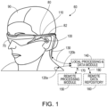
- FIG. 1 illustrates an example wearable display system 60 that incorporates a high index material grating.
- the display system 60 includes a display or eyepiece 70, and various mechanical and electronic modules and systems to support the functioning of that display 70.
- the display 70 may be coupled to a frame 80, which is wearable by a display system user 90 and which is configured to position the display 70 in front of the eyes of the user 90.
- the display 70 may be considered eyewear in some embodiments.
- a speaker 100 is coupled to the frame 80 and is positioned adjacent the ear canal of the user 90.
- the display system may also include one or more microphones 110 to detect sound.
- the microphone 110 can allow the user to provide inputs or commands to the system 60 (e.g., the selection of voice menu commands, natural language questions, etc.), and/or can allow audio communication with other persons (e.g., with other users of similar display systems).
- the microphone 110 can also collect audio data from the user's surroundings (e.g., sounds from the user and/or environment).
- the display system may also include a peripheral sensor 120 a, which may be separate from the frame 80 and attached to the body of the user 90 (e.g., on the head, torso, an extremity, etc.).
- the peripheral sensor 120 a may acquire data characterizing the physiological state of the user 90 in some embodiments.
- the display 70 is operatively coupled by a communications link 130, such as by a wired lead or wireless connectivity, to a local data processing module 140 which may be mounted in a variety of configurations, such as fixedly attached to the frame 80, fixedly attached to a helmet or hat worn by the user, embedded in headphones, or removably attached to the user 90 (e.g., in a backpack-style configuration or in a belt-coupling style configuration).
- the sensor 120 a may be operatively coupled by communications link 120 b (e.g., a wired lead or wireless connectivity) to the local processor and data module 140.
- the local processing and data module 140 may include a hardware processor, as well as digital memory, such as non-volatile memory (e.g., flash memory or a hard disk drive), both of which may be utilized to assist in the processing, caching, and storage of data.
- the data may include data 1) captured from sensors (which may be, e.g., operatively coupled to the frame 80 or otherwise attached to the user 90), such as image capture devices (e.g., cameras), microphones, inertial measurement units, accelerometers, compasses, GPS units, radio devices, gyros, and/or other sensors disclosed herein; and/or 2) acquired and/or processed using a remote processing module 150 and/or a remote data repository 160 (including data relating to virtual content), possibly for passage to the display 70 after such processing or retrieval.
- sensors which may be, e.g., operatively coupled to the frame 80 or otherwise attached to the user 90
- image capture devices e.g., cameras
- microphones e.g., inertial measurement units
- the local processing and data module 140 may be operatively coupled by communication links 170, 180, such as via a wired or wireless communication links, to the remote processing module 150 and the remote data repository 160 such that these remote modules 150, 160 are operatively coupled to each other and available as resources to the local processing and data module 140.
- the local processing and data module 140 may include one or more of the image capture devices, microphones, inertial measurement units, accelerometers, compasses, GPS units, radio devices, and/or gyros. In some other embodiments, one or more of these sensors may be attached to the frame 80, or may be standalone devices that communicate with the local processing and data module 140 by wired or wireless communication pathways.
- the remote processing module 150 may include one or more processors to analyze and process data, such as image and audio information.
- the remote data repository 160 may be a digital data storage facility, which may be available through the internet or other networking configuration in a "cloud" resource configuration.
- the remote data repository 160 may include one or more remote servers, which provide information (e.g., information for generating augmented reality content) to the local processing and data module 140 and/or the remote processing module 150.
- information e.g., information for generating augmented reality content
- all data is stored and all computations are performed in the local processing and data module, allowing fully autonomous use from a remote module.
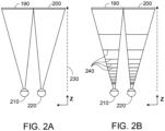
- FIG. 2A illustrates a conventional display system for simulating three-dimensional image data for a user.
- the images 190, 200 are spaced from the eyes 210, 220 by a distance 230 along an optical or z-axis that is parallel to the line of sight of the user.
- the images 190, 200 are flat and the eyes 210, 220 may focus on the images by assuming a single accommodated state.
- Such 3-D display systems rely on the human visual system to combine the images 190, 200 to provide a perception of depth and/or scale for the combined image.
- Such systems can be uncomfortable for some users, however, since they simply provide image information at a single accommodated state and work against the "accommodation-vergence reflex.”
- Display systems that provide a better match between accommodation and vergence may form more realistic and comfortable simulations of three-dimensional image data.
- FIG. 2B illustrates aspects of an approach for simulating three-dimensional image data using multiple depth planes.
- the eyes 210, 220 assume different accommodated states to focus on objects at various distances on the z-axis. Consequently, a particular accommodated state may be said to be associated with a particular one of the illustrated depth planes 240, which has an associated focal distance, such that objects or parts of objects in a particular depth plane are in focus when the eye is in the accommodated state for that depth plane.
- three-dimensional image data may be simulated by providing different presentations of an image for each of the eyes 210, 220, and also by providing different presentations of the image corresponding to multiple depth planes.
- the respective fields of view of the eyes 210, 220 are shown as being separate for clarity of illustration, they may overlap, for example, as distance along the z-axis increases.
- the depth planes are shown as being flat for ease of illustration, it will be appreciated that the contours of a depth plane may be curved in physical space, such that all features in a depth plane are in focus with the eye in a particular accommodated state.
- the distance between an object and an eye 210 or 220 may also change the amount of divergence of light from that object, as viewed by that eye.
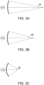
- FIGS. 3A-3C illustrate relationships between distance and the divergence of light rays.
- the distance between the object and the eye 210 is represented by, in order of decreasing distance, R1, R2, and R3.
- R1, R2, and R3 As shown in FIGS. 3A-3C , the light rays become more divergent as distance to the object decreases. As distance increases, the light rays become more collimated. Stated another way, it may be said that the light field produced by a point (the object or a part of the object) has a spherical wavefront curvature, which is a function of how far away the point is from the eye of the user.
- the curvature increases with decreasing distance between the object and the eye 210. Consequently, at different depth planes, the degree of divergence of light rays is also different, with the degree of divergence increasing with decreasing distance between depth planes and the user's eye 210. While only a single eye 210 is illustrated for clarity of illustration in FIGS. 3A-3C and other figures herein, it will be appreciated that the discussions regarding the eye 210 may be applied to both eyes 210 and 220 of a user.
- a highly believable simulation of perceived depth may be achieved by providing, to the eye, different presentations of an image corresponding to each of a limited number of depth planes.
- the different presentations may be separately focused by the user's eye, thereby helping to provide the user with depth cues based on the amount of accommodation of the eye required to bring into focus different image features for the scene located on different depth planes and/or based on observing different image features on different depth planes being out of focus.
- the waveguide assembly 260 may also include a plurality of features 320, 330, 340, 350 between the waveguides.
- the features 320, 330, 340, 350 may be one or more lenses.
- the waveguides 270, 280, 290, 300, 310 and/or the plurality of lenses 320, 330, 340, 350 may be configured to send image information to the eye with various levels of wavefront curvature or light ray divergence. Each waveguide level may be associated with a particular depth plane and may be configured to output image information corresponding to that depth plane.
- Image injection devices 360, 370, 380, 390, 400 may function as a source of light for the waveguides and may be utilized to inject image information into the waveguides 270, 280, 290, 300, 310, each of which may be configured, as described herein, to distribute incoming light across each respective waveguide, for output toward the eye 210.
- the each of the input surfaces 460, 4 70, 480, 490, 500 may be an edge of a corresponding waveguide, or may be part of a major surface of the corresponding waveguide (that is, one of the waveguide surfaces directly facing the world 510 or the user's eye 210).
- a beam of light e.g., a collimated beam
- a single one of the image injection devices 360, 370, 380, 390, 400 may be associated with, and inject light into, a plurality (e.g., three) of the waveguides 270, 280, 290, 300,310.
- the image injection devices 360, 370, 380, 390, 400 are discrete displays that each produce image information for injection into a corresponding waveguide 270, 280, 290, 300, 310, respectively.
- the image injection devices 360, 370, 380, 390, 400 are the output ends of a single multiplexed display which may transmit image information via one or more optical conduits (such as fiber optic cables) to each of the image injection devices 360, 370, 380, 390, 400.
- the image information provided by the image injection devices 360, 370, 380, 390, 400 may include light of different wavelengths, or colors.
- the light injected into the waveguides 270, 280, 290, 300, 310 is provided by a light projector system 520, which includes a light module 530, which may include a light source or light emitter, such as a light emitting diode (LED).
- the light from the light module 530 may be directed to, and modulated by, a light modulator 540 (e.g., a spatial light modulator), via a beamsplitter (BS) 550.
- the light modulator 540 may spatially and/or temporally change the perceived intensity of the light injected into the waveguides 270, 280, 290, 300, 310.
- Examples of spatial light modulators include liquid crystal displays (LCD), including a liquid crystal on silicon (LCOS) displays, and digital light processing (DLP) displays.
- LCD liquid crystal displays
- LCOS liquid crystal on silicon
- DLP digital light processing
- the light projector system 520 may be attached to the frame 80 ( FIG. 1 ).
- the light projector system 520 may be part of a temporal portion (e.g., ear stem 82) of the frame 80 or disposed at an edge of the display 70.
- the light module 530 may be separate from the BS 550 and/or light modulator 540.
- the display system 250 may be a scanning fiber display comprising one or more scanning fibers to project light in various patterns (e.g., raster scan, spiral scan, Lissajous patterns, etc.) into one or more waveguides 270, 280, 290, 300, 310 and ultimately into the eye 210 of the user.
- the illustrated image injection devices 360, 370, 380, 390, 400 may schematically represent a single scanning fiber or a bundle of scanning fibers configured to inject light into one or a plurality of the waveguides 270, 280, 290, 300, 310.
- the illustrated image injection devices 360, 370, 380, 390, 400 may schematically represent a plurality of scanning fibers or a plurality of bundles of scanning fibers, each of which are configured to inject light into an associated one of the waveguides 270, 280, 290, 300, 310.
- One or more optical fibers may transmit light from the light module 530 to the one or more waveguides 270, 280, 290, 300, and 310.
- one or more intervening optical structures may be provided between the scanning fiber, or fibers, and the one or more waveguides 270, 280, 290, 300, 310 to, for example, redirect light exiting the scanning fiber into the one or more waveguides 270,280,290,300,310.
- a controller 560 controls the operation of the stacked waveguide assembly 260, including operation of the image injection devices 360, 370, 380, 390, 400, the light source 530, and the light modulator 540.
- the controller 560 is part of the local data processing module 140.
- the controller 560 includes programing (e.g., instructions in a non-transitory medium) that regulates the timing and provision of image information to the waveguides 270, 280, 290, 300, 310.
- the controller may be a single integral device, or a distributed system connected by wired or wireless communication channels.
- the controller 560 may be part of the processing modules 140 or 150 ( FIG. 1 ) in some embodiments.
- the waveguides 270, 280, 290, 300, 310 may be configured to propagate light within each respective waveguide by total internal reflection (TIR).
- the waveguides 270, 280, 290, 300, 310 may each be planar or have another shape (e.g., curved), with major top and bottom surfaces and edges extending between those major top and bottom surfaces.
- the waveguides 270, 280, 290, 300, 310 may each include out-coupling optical elements 570, 580, 590, 600, 610 that are configured to extract light out of a waveguide by redirecting the light, propagating within each respective waveguide, out of the waveguide to output image information to the eye 210.
- Extracted light may also be referred to as out-coupled light and the out-coupling optical elements light may also be referred to light extracting optical elements.
- An extracted beam of light may be output by the waveguide at locations at which the light propagating in the waveguide strikes a light extracting optical element.
- the out-coupling optical elements 570, 580, 590, 600, 610 may be, for example, diffractive optical features, including diffractive gratings, as discussed further herein.
- out-coupling optical elements 570, 580, 590, 600, 610 are illustrated as being disposed at the bottom major surfaces of the waveguides 270, 280, 290, 300, 310, in some embodiments they may be disposed at the top and/or bottom major surfaces, and/or may be disposed directly in the volume of the waveguides 270, 280, 290, 300, 310, as discussed further herein. In some embodiments, the out-coupling optical elements 570, 580, 590, 600, 610 may be formed in a layer of material that is attached to a transparent substrate to form the waveguides 270, 280, 290, 300, 310.
- the waveguides 270, 280, 290, 300, 310 may be a monolithic piece of material and the out-coupling optical elements 570, 580, 590, 600, 610 may be formed on a surface and/or in the interior of that piece of material.
- Each waveguide 270, 280, 290, 300, 310 may output light to form an image corresponding to a particular depth plane.
- the waveguide 270 nearest the eye may deliver collimated beams of light to the eye 210.
- the collimated beams of light may be representative of the optical infinity focal plane.
- the next waveguide up 280 may output collimated beams of light which pass through the first lens 350 (e.g., a negative lens) before reaching the eye 210.
- the first lens 350 may add a slight convex wavefront curvature to the collimated beams so that the eye/brain interprets light coming from that waveguide 280 as originating from a first focal plane closer inward toward the eye 210 from optical infinity.
- the third waveguide 290 passes its output light through both the first lens 350 and the second lens 340 before reaching the eye 210.
- the combined optical power of the first lens 350 and the second lens 340 may add another incremental amount of wavefront curvature so that the eye/brain interprets light coming from the third waveguide 290 as originating from a second focal plane that is even closer inward from optical infinity than was light from the second waveguide 280.
- the other waveguide layers 300, 310 and lenses 330, 320 are similarly configured, with the highest waveguide 310 in the stack sending its output through all of the lenses between it and the eye for an aggregate focal power representative of the closest focal plane to the person.
- a compensating lens layer 620 may be disposed at the top of the stack to compensate for the aggregate optical power of the lens stack 320, 330, 340, 350 below.
- Such a configuration provides as many perceived focal planes as there are available waveguide/lens pairings.
- Both the out-coupling optical elements of the waveguides and the focusing aspects of the lenses may be static (i.e., not dynamic or electro-active). In some alternative embodiments, either or both may be dynamic using electro-active features.
- two or more of the waveguides 270, 280, 290, 300, 310 may have the same associated depth plane.
- multiple waveguides 270, 280, 290, 300, 310 may output images set to the same depth plane, or multiple subsets of the waveguides 270, 280, 290, 300, 310 may output images set to the same plurality of depth planes, with one set for each depth plane. This can provide advantages for forming a tiled image to provide an expanded field of view at those depth planes.
- the out-coupling optical elements 570, 580, 590, 600, 610 may be configured to both redirect light out of their respective waveguides and to output this light with the appropriate amount of divergence or collimation for a particular depth plane associated with the waveguide.
- waveguides having different associated depth planes may have different configurations of out-coupling optical elements 570, 580, 590, 600, 610, which output light with a different amount of divergence depending on the associated depth plane.
- the light extracting optical elements 570, 580, 590, 600, 610 may be volumetric or surface features, which may be configured to output light at specific angles.
- the light extracting optical elements 570, 580, 590, 600, 610 may be volume holograms, surface holograms, and/or diffraction gratings.
- the features 320, 330, 340, 350 may not be lenses; rather, they may simply be spacers (e.g., cladding layers and/or structures for forming air gaps).
- the out-coupling optical elements 570, 580, 590, 600, 610 are diffractive features with a diffractive efficiency sufficiently low such that only a portion of the power of the light in a beam is re-directed toward the eye 210 with each interaction, while the rest continues to move through a waveguide via TIR. Accordingly, the exit pupil of the light module 530 is replicated across the waveguide to create a plurality of output beams carrying the image information from light source 530, effectively expanding the number of locations where the eye 210 may intercept the replicated light source exit pupil.
- These diffractive features may also have a variable diffractive efficiency across their geometry to improve uniformity of light output by the waveguide.
- one or more diffractive features may be switchable between “on” states in which they actively diffract, and "off states in which they do not significantly diffract.
- a switchable diffractive element may include a layer of polymer dispersed liquid crystal in which microdroplets form a diffraction pattern in a host medium, and the refractive index of the microdroplets may be switched to substantially match the refractive index of the host material (in which case the pattern does not appreciably diffract incident light) or the microdroplet may be switched to an index that does not match that of the host medium (in which case the pattern actively diffracts incident light).
- a camera assembly 630 may be provided to capture images of the eye 210, parts of the eye 210, or at least a portion of the tissue surrounding the eye 210 to, for example, detect user inputs, extract biometric information from the eye, estimate and track the gaze direction of the eye, to monitor the physiological state of the user, etc.
- the camera assembly 630 may include an image capture device and a light source to project light (e.g., IR or near-IR light) to the eye, which may then be reflected by the eye and detected by the image capture device.
- the light source includes light emitting diodes ("LEDs"), emitting in IR or near-IR.
- the camera assembly 630 may be attached to the frame 80 ( FIG. 1 ) and may be in electrical communication with the processing modules 140 or 150, which may process image information from the camera assembly 630 to make various determinations regarding, for example, the physiological state of the user, the gaze direction of the wearer, iris identification, etc. In some embodiments, one camera assembly 630 may be utilized for each eye, to separately monitor each eye.
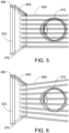
- FIG. 5 illustrates an example of exit beams output by a waveguide.
- One waveguide is illustrated (with a perspective view), but other waveguides in the waveguide assembly 260 ( FIG. 4 ) may function similarly.
- Light 640 is injected into the waveguide 270 at the input surface 460 of the waveguide 270 and propagates within the waveguide 270 by TIR. Through interaction with diffractive features, light exits the waveguide as exit beams 650.
- the exit beams 650 replicate the exit pupil from a projector device which projects images into the waveguide. Any one of the exit beams 650 includes a sub-portion of the total energy of the input light 640.
- the exit beams 650 are illustrated as being substantially parallel in FIG. 6 but, as discussed herein, some amount of optical power may be imparted depending on the depth plane associated with the waveguide 270.
- Parallel exit beams may be indicative of a waveguide with out-coupling optical elements that out-couple light to form images that appear to be set on a depth plane at a large distance (e.g., optical infinity) from the eye 210.
- Other waveguides or other sets of out-coupling optical elements may output an exit beam pattern that is more divergent, as shown in FIG. 6 , which would require the eye 210 to accommodate to a closer distance to bring it into focus on the retina and would be interpreted by the brain as light from a distance closer to the eye 210 than optical infinity.
- wearable display systems e.g., including optical elements used in wearable display systems
- wearable display systems can be found in U.S. Patent Application Publication No. 2019/0187474, filed December 14, 2018 , and entitled "EYEPIECES FOR AUGMENTED REALITY DISPLAY SYSTEM,”.
- wearable display system 60 includes one or more optical elements having one or more grating structures that enhance an optical performance of the wearable display system.
- one or more optical elements forming an eyepiece of the wearable display system 60 can include gratings structures defined along their peripheries (e.g., along an interface between an optical element and another optical element, or along an interface between an optical element and air, such as out-coupling optical elements 570, 580, 590, 600, 610), and formed from one or more high index materials, such as such as titanium dioxide (TiO 2 ), silicon carbide (SiC), and/or lithium niobate (LiNbO 3 ).
- TiO 2 titanium dioxide
- SiC silicon carbide
- LiNbO 3 lithium niobate
- each of the waveguides 270, 280, 290, 300, 310 can be configured to send image information to the eye according to multiple wavelengths of light (e.g., corresponding to a red-green-blue image).
- high refractive index substrates such as LiNbO 3 or SiC
- RGB red-green-blue
- the use of certain types of grating structures, such as binary or blazed structures can result poor eyepiece performance, as such grating structures may impart color-selective properties onto the eyepiece.
- the grating structures may cause shorter wavelengths of light to be diffracted more efficiently compared to longer wavelengths of light. This effect can be undesirable in some circumstances. For example, this effect may make it more difficult to obtain a good color balance or uniformity in single layer RGB eyepiece while maintaining an acceptable eyepiece efficiency.
- an eyepiece can be formed from wavelength selective volume holographic materials (e.g., instead of using the techniques described herein), but they may have field of view limitations stemming from their lower refractive indices (e.g., around 1.5).
- some materials can have similar refractive indices at a specific wavelength ⁇ 0 , while exhibiting different dispersions (e.g., refractive index with respect to wavelength). As a result, light crossing the interface between these materials will not be affected at that specific wavelength ⁇ 0 , while being affected at other wavelengths. If the interface includes a grating structure, the diffraction efficiency of that grating structure will be close to zero around wavelength ⁇ 0 , because there would be no phase modulation. However, light would be diffracted at other wavelengths, with a diffraction efficiency that is proportional to the refractive index difference between the materials.
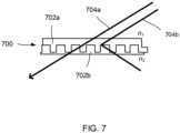
- FIG. 7 shows, in cross-section, an example grating structure 700 defined at an interface between a first optical element 702a (having a refractive index of n 1 ) and a second optical element 702b (having a different refractive index n 2 ).
- a first optical element 702a having a refractive index of n 1
- a second optical element 702b having a different refractive index n 2 .
- light 704a having a different wavelength ⁇ 1 is diffracted as it passes through the grating structure 700, with a diffraction efficiency that is proportional to the difference in refractive index between the two materials (e.g., the difference between n 1 and n 2 ).
- the spectral response of the grating structure is dictated, at least in part, by the refractive indices and the dispersion properties of the materials used to form the grating structure. Accordingly, a particular spectral response of the grating structure can be achieved by selecting certain materials (e.g., having certain refractive indices and the dispersion properties) to form the grating structure.
- spectral response of the grating structure is dictated, at least in part, by the physical dimensions of the gratings (e.g., their height, width, periodicity, duty cycle, etc.). Accordingly, a particular spectral response of the grating structure can be achieved by further forming gratings having certain dimensions using the selected materials.
- FIG. 8A shows, in cross-section, a single unit 802 of a grating structure 800.
- the unit 802 can repeat one or more times periodically along a periphery of an optical element (e.g., at an interface between the optical element and another optical element, or along an interface between the optical element and air).
- the unit 802 includes a base portion 804 composed of a first material, and protrusion 806 composed of the first material and extending from the base portion 804.
- the unit 802 also includes filling portions 808 composed of a second material different from the first material, and disposed on the base portion 504 along opposing sides of the protrusion 806. As shown in FIGS.
- the unit 802 repeats periodically along the periphery of an optical element 810, forming the grating structure 800 (e.g., a "binary" grating in filling portions disposed between each protrusion).
- the optical element 810 receives light through the grating structure 800 (e.g., from a light source 812), and light 814 incident upon the grating structure 800 is diffracted as it enters the optical element 810.
- the grating structure 800 e.g., a "binary" grating in filling portions disposed between each protrusion.
- the optical element 810 emits light 816 through the grating structure 800 (e.g., towards another optical element, into the air, and/or towards a user's eye), and light incident upon the grating structure 800 is diffracted as it exits the optical element 810.
- one or more of the out-coupling optical elements 570, 580, 590, 600, 610 can include a respective grating struvtuce 800.
- the light to be coupled out propagates through the substrate by total internal reflection (TIR) and is extracted from the waveguide by the grating structure.
- TIR total internal reflection
- the unit 802 has a cross-sectional width w t (e.g., corresponding to the periodicity of the unit 802), and a cross-sectional height h t (e.g., corresponding to the maximal height of the unit 802).
- the protrusion 506 has a cross-sectional width w 1 and a cross-sectional height h 1 (e.g., the difference in height between the top surface of the protrusion 806 and the top surface of the base portion 504).
- the base portion 804 has a cross-sectional width w t , and a cross-sectional height h 3 .
- Each filler portion 808 has a cross-sectional width w 2 , and a cross-sectional height h 2 .
- Each of the parameters w t , w 1 . w 2 , h t , h 1 , h 2 , h 2 , and h 3 can be selected to impart certain optical properties with respect the grating structure.
- the materials of the base portion 804, protrusion 806, and filling portions 808 also can be selected (e.g., based at least in part on their respective refractive indices and the dispersion properties) to impart certain optical properties with respect the grating structure.
- the repeating period of the grating structures is sufficiently small (e.g., between 250 nm and 400 nm)
- TIR total interface reflection
- these parameters can be selected such that the grating structure exhibits a diffraction efficiency that is uniform or more uniform over a particular range of incident angles of light and with respect to particular wavelengths of light (e.g., compared to grating structures designed using techniques different from those described herein).
- the base portion 504 and the protrusion 506 can be formed from SiC (e.g., through a deposition and etching process), and the filling portions 508 can be formed from TiO 2 (e.g., through a deposition process, such as sputtering).
- the refractive index of the SiC portions can be between 2.65 and 2.8
- the refractive index of the TiO2 portions can be between 2.2 and 2.6.
- the grating structure can be formed such that w 1 is equal to or approximately equal to 140 nm (e.g., between 80 nm and 200 nm), w 2 is equal to or approximately equal to 34 nm (e.g., between 30 nm and 200 nm), h 1 is equal to or approximately equal to 90 nm (e.g., between 40 nm and 150 nm), h 2 is equal to or approximately equal to 80 nm (e.g., between 40 nm and 150 nm), w t is equal to or approximately equal to 208 nm (e.g., between 150 nm and 400 nm. It should be noted that the numbers given in the example above correspond to the out-coupling of TIR-guided light within the substrate.
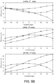
- FIG. 9A shows the angular response of a binary grating structure etched in SiC (e.g., without any filling portions of TiO 2 deposited between the protrusions of the grating structure) with respect to three different wavelengths of light (red, green and blue).
- FIG. 9B shows the angular response of a similar binary grating structure etched in SiC—but also having filling portions of TiO 2 deposited between the protrusions of the grating structure (e.g., as shown in FIGS. 5A-5C)-with respect to the same three wavelengths of light (red, green and blue). As shown in FIGS.
- the addition of the filling portions of TiO 2 increases a diffraction efficiency of the grating structure across a range of incident angles of light (e.g., from -20° to 20°) with respect to each of the different wavelengths of light. Accordingly, light incident on the grating structures described herein exhibit are less likely to exhibit color-dependent or incident angle-dependent diffraction characteristics.
- optical elements having the grating structures described herein may be particularly suitable for use as eyepieces in a wearable display headset.
- a wearable display headset may be configured to display multicolored images (e.g., RGB images).
- one or more optical elements of the wearable display headset e.g., the eyepiece and/or any other optical elements
- one of the out-coupling optical elements 570, 580, 590, 600, 610 may be diffractive optical features, including the diffractive gratings described herein.
- FIG. 10A shows an intensity map of light emitted by an eyepiece including a binary grating structure etched in SiC (e.g., without any filling portions of TiO 2 deposited between the protrusions of the grating structure, as described with respect to FIG. 6A ).
- FIG. 10B shows an intensity map of light emitted by a similar binary grating structure etched in SiC-but also having filling portions of TiO 2 deposited between the protrusions of the grating structure (e.g., as described with respect to FIGS. 8A-8C and 9B ).
- the addition of the filling portions of TiO 2 increases the uniformity of projected light.
- FIG. 10A exhibits localized bands of high-intensity light (e.g., a C-shaped artifact of higher-intensity light surrounded by regions of lower-intensity light).
- the eyepiece of FIG. 10B exhibits a more uniform light intensity pattern.
- the base portion and the protrusions of a grating structure can be composed of SiC, LiNbO 3 , or a combination thereof.
- the filling portions can be composed of TiO 2 .
- the principles described herein can be applied to other combination of materials in which the waveguide substrate exhibits a higher refractive index and a lower dispersion than the coating material. Examples include diamond/LiNbO 3 and diamond/SrTiO 3 systems.
- the refractive index of a material may vary, depending on the manner in which the material is deposited (e.g., on an underlying substrate).
- the refractive index of a sputtered layer of titanium dioxide can be varied between 2.25 and 2.65 by changing the deposition parameters, such as the temperature and/or the pressure at which the materials were sputtered onto the underlying material. Accordingly, the spectral response of a grating structure can be "tuned" by changing the deposition conditions of one or more materials used to define the grating structure.
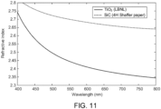
- FIG. 11 shows the refractive index curves of crystalline SiC and TiO 2 deposited according to the atomic deposition (ALD) technique.
- ALD atomic deposition
- Each of these materials exhibits a refractive index that varies with respect to the incident wavelength of light (e.g., defining particular refractive index curves).
- These refractive index curves can be modified, at least in part, by varying the deposition parameters of each of the materials (e.g., the temperature and/or pressure when the materials are sputtered onto a substrate or other structure).
- each repeating unit of the grating includes a protrusion that is rectangular in cross-section (e.g., forming a binary grating).
- each unit of the grating can include differently shaped protrusions.
- each unit of a grating can include a protrusion that is rectangular in cross-section (e.g., a isosceles triangle as shown in FIG. 12A , a right triangle as shown in FIG. 12B , etc.).
- any other grating configurations also can be used, depending on the implementation.
- the technique is also applicable to two-dimensional diffractive lattices such as two-dimensional arrays of rods, squares, or pyramids.
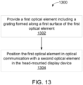
- FIG. 13 shows an embodiment of method 1300 for constructing a head-mounted display device using the optical elements and grating structures described herein.
- a first optical element is provided (step 1302).
- the first optical element includes a grating formed along a first surface of the first optical element.
- the grating includes plurality of protrusions including a first material having a first optical dispersion profile for visible wavelengths of light, and a second material deposited between at least some of the plurality of protrusions along the first surface of the first optical element.
- the second material has a second optical dispersion profile for visible wavelengths of light.
- Example first optical elements are shown and described with respect to FIGS. 8A-8C .
- the second material can be titanium dioxide (TiO 2 ).
- the first material can be silicon carbide (SiC) or lithium niobate (LiNbO 3 ).
- the grating can be formed by etching a plurality of channels onto the first optical element along the first surface. Each channel can have a first depth. Further, the second material can be depositied between at least some of the plurality of protrusions along the first surface. An example of this configuration is shown, for example, in FIGS. 8A-8C .
- each channel can have a substantially rectangular cross-section. In some implementations, each channel can have a substantially equal width (e.g., approximately 68 nm).
- depositing the second material can include depositing the second material into at least some of the channels.
- depositing the second material can include sputtering the second material into at least some of the channels.
- the second material can be sputtered at different temperatures and/or pressures to varying the optical properties (e.g., the refractive index) of the material.
- the second material can be deposited such that it extends a first height within the channel.
- the first depth can be greater than the first height.
- the first depth can be approximately 90 nm, and the first height can be approximately 80 nm.
- the grating can be formed according to a period along a length of the first surface.
- the period can correspond to a length of approximately 208 nm.
- the first optical element is positioned in optical communication with a second optical element in the head-mounted display device (step 1304).
- Example configurations of a first optical element and a second optical element in a head-mounted display device are shown and described with respect to FIGS. 1 and 4-6 .
- Some implementations of subject matter and operations described in this specification can be implemented in digital electronic circuitry, or in computer software, firmware, or hardware, including the structures disclosed in this specification and their structural equivalents, or in combinations of one or more of them.
- the local processing and data module 140, the remote processing module 150, and/or the remote data repository 160 can be implemented using digital electronic circuitry, or in computer software, firmware, or hardware, or in combinations of one or more of them.
- the process 1300 shown in FIG. 1300 can be implemented, at least in part, using digital electronic circuitry, or in computer software, firmware, or hardware, or in combinations of one or more of them (e.g., as a part of an automated or computer-assisted manufacturing process).
- Some implementations described in this specification can be implemented as one or more groups or modules of digital electronic circuitry, computer software, firmware, or hardware, or in combinations of one or more of them. Although different modules can be used, each module need not be distinct, and multiple modules can be implemented on the same digital electronic circuitry, computer software, firmware, or hardware, or combination thereof.
- Some implementations described in this specification can be implemented as one or more computer programs, i.e., one or more modules of computer program instructions, encoded on computer storage medium for execution by, or to control the operation of, data processing apparatus.
- a computer storage medium can be, or can be included in, a computer-readable storage device, a computer-readable storage substrate, a random or serial access memory array or device, or a combination of one or more of them.
- a computer storage medium is not a propagated signal
- a computer storage medium can be a source or destination of computer program instructions encoded in an artificially generated propagated signal.
- the computer storage medium can also be, or be included in, one or more separate physical components or media (e.g., multiple CDs, disks, or other storage devices).
- the term "data processing apparatus” encompasses all kinds of apparatus, devices, and machines for processing data, including by way of example a programmable processor, a computer, a system on a chip, or multiple ones, or combinations, of the foregoing.
- the apparatus can include special purpose logic circuitry, e.g., an FPGA (field programmable gate array) or an ASIC (application specific integrated circuit).
- the apparatus can also include, in addition to hardware, code that creates an execution environment for the computer program in question, e.g., code that constitutes processor firmware, a protocol stack, a database management system, an operating system, a cross-platform runtime environment, a virtual machine, or a combination of one or more of them.
- the apparatus and execution environment can realize various different computing model infrastructures, such as web services, distributed computing and grid computing infrastructures.
- a computer program (also known as a program, software, software application, script, or code) can be written in any form of programming language, including compiled or interpreted languages, declarative or procedural languages.
- a computer program may, but need not, correspond to a file in a file system.
- a program can be stored in a portion of a file that holds other programs or data (e.g., one or more scripts stored in a markup language document), in a single file dedicated to the program in question, or in multiple coordinated files (e.g., files that store one or more modules, sub programs, or portions of code).
- a computer program can be deployed to be executed on one computer or on multiple computers that are located at one site or distributed across multiple sites and interconnected by a communication network.
- Some of the processes and logic flows described in this specification can be performed by one or more programmable processors executing one or more computer programs to perform actions by operating on input data and generating output.
- the processes and logic flows can also be performed by, and apparatus can also be implemented as, special purpose logic circuitry, e.g., an FPGA (field programmable gate array) or an ASIC (application specific integrated circuit).
- processors suitable for the execution of a computer program include, by way of example, both general and special purpose microprocessors, and processors of any kind of digital computer.
- a processor will receive instructions and data from a read only memory or a random access memory or both.
- a computer includes a processor for performing actions in accordance with instructions and one or more memory devices for storing instructions and data.
- a computer may also include, or be operatively coupled to receive data from or transfer data to, or both, one or more mass storage devices for storing data, e.g., magnetic, magneto optical disks, or optical disks.
- mass storage devices for storing data, e.g., magnetic, magneto optical disks, or optical disks.
- a computer need not have such devices.
- Devices suitable for storing computer program instructions and data include all forms of non-volatile memory, media and memory devices, including by way of example semiconductor memory devices (e.g., EPROM, EEPROM, flash memory devices, and others), magnetic disks (e.g., internal hard disks, removable disks, and others), magneto optical disks, and CD ROM and DVD-ROM disks.
- semiconductor memory devices e.g., EPROM, EEPROM, flash memory devices, and others
- magnetic disks e.g., internal hard disks, removable disks, and others
- magneto optical disks e.g., CD ROM and DVD-ROM disks.
- the processor and the memory can be supplemented by, or incorporated in, special purpose logic circuitry.
- a computer having a display device (e.g., a monitor, or another type of display device) for displaying information to the user and a keyboard and a pointing device (e.g., a mouse, a trackball, a tablet, a touch sensitive screen, or another type of pointing device) by which the user can provide input to the computer.
- a display device e.g., a monitor, or another type of display device
- a keyboard and a pointing device e.g., a mouse, a trackball, a tablet, a touch sensitive screen, or another type of pointing device
- Other kinds of devices can be used to provide for interaction with a user as well; for example, feedback provided to the user can be any form of sensory feedback, e.g., visual feedback, auditory feedback, or tactile feedback; and input from the user can be received in any form, including acoustic, speech, or tactile input.
- a computer can interact with a user by sending documents to and receiving documents from a device that is used
- a computer system may include a single computing device, or multiple computers that operate in proximity or generally remote from each other and typically interact through a communication network.
- Examples of communication networks include a local area network ("LAN”) and a wide area network (“WAN”), an inter-network (e.g., the Internet), a network comprising a satellite link, and peer-to-peer networks (e.g., ad hoc peer-to-peer networks).
- LAN local area network
- WAN wide area network
- Internet inter-network
- peer-to-peer networks e.g., ad hoc peer-to-peer networks.
- a relationship of client and server may arise by virtue of computer programs running on the respective computers and having a client-server relationship to each other.
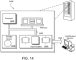
- FIG. 14 shows an example computer system 1400 that includes a processor 1410, a memory 1420, a storage device 1430 and an input/output device 1440.
- the processor 1410 is capable of processing instructions for execution within the system 1400.
- the processor 1410 is a single-threaded processor, a multi-threaded processor, or another type of processor.
- the processor 1410 is capable of processing instructions stored in the memory 1420 or on the storage device 1430.
- the memory 1420 and the storage device 1430 can store information within the system 1400.
- the input/output device 1440 provides input/output operations for the system 1400.
- the input/output device 1440 can include one or more of a network interface device, e.g., an Ethernet card, a serial communication device, e.g., an RS-232 port, and/or a wireless interface device, e.g., an 802.11 card, a 3G wireless modem, a 4G wireless modem, etc.
- the input/output device can include driver devices configured to receive input data and send output data to other input/output devices, e.g., keyboard, printer and display devices 1460.
- mobile computing devices, mobile communication devices, and other devices can be used.
Landscapes
- Physics & Mathematics (AREA)
- General Physics & Mathematics (AREA)
- Optics & Photonics (AREA)
- Spectroscopy & Molecular Physics (AREA)
- Engineering & Computer Science (AREA)
- Manufacturing & Machinery (AREA)
- Diffracting Gratings Or Hologram Optical Elements (AREA)
- Mechanical Optical Scanning Systems (AREA)
Claims (15)
- Head-Mounted-Display-Vorrichtung (60), Folgendes umfassend:mehrere optische Elemente (810) in optischer Verbindung, wobei die mehreren optischen Elemente dafür konfiguriert sind, während des Betriebes der Head-Mounted-Display-Vorrichtung ein Bild in ein Sichtfeld eines Benutzers (90) zu projizieren, der die Head-Mounted-Display-Vorrichtung (60) trägt,wobei ein erstes optisches Element (810) der mehreren optischen Elemente dafür konfiguriert ist, Licht von einem zweiten optischen Element der mehreren optischen Elemente zu empfangen,
wobei das erste optische Element (810) ein Gitter (800) entlang eines Außenumfangs des ersten optischen Elements (810) definiert, wobei das Gitter (800) Folgendes umfasst:mehrere Vorsprünge (806), die sich von einem Basisabschnitt (804) des ersten optischen Elements (810) aus erstrecken, wobei die Vorsprünge (806) ein erstes Material umfassen, das ein erstes Profil optischer Dispersion für Licht sichtbarer Wellenlänge aufweist, und jeder der Vorsprünge (806) eine erste Oberfläche gegenüber dem Basisabschnitt (804) des ersten optischen Elements (810) umfasst, undein zweites Material (808), das entlang des Basisabschnitts (804) des ersten optischen Elements (810) zwischen zumindest einigen der mehreren Vorsprünge (806) angeordnet ist, wobei das zweite Material (808) ein zweites Profil optischer Dispersion für Licht sichtbarer Wellenlänge aufweist,wobei auf der ersten Oberfläche der Vorsprünge (806) kein zusätzliches Material vorhanden ist. - Head-Mounted-Display-Vorrichtung (60) nach Anspruch 1, wobei das zweite Material (808) Titanoxid (TiO2) ist und/oder das erste Material Siliziumcarbid (SiC) oder Lithiumniobat (LiNbO3) ist.
- Head-Mounted-Display-Vorrichtung (60) nach Anspruch 1, wobei der Basisabschnitt (804) des ersten optischen Elements (810) das erste Material umfasst, aus dem gleichen Material wie die mehreren Vorsprünge (806) besteht oder integral mit den mehreren Vorsprüngen (806) gebildet ist.
- Head-Mounted-Display-Vorrichtung (60) nach Anspruch 1, wobei jeder Vorsprung (806) einen im Wesentlichen rechteckigen Querschnitt aufweist.
- Head-Mounted-Display-Vorrichtung (60) nach Anspruch 1, wobei sich jeder Vorsprung (806) in eine erste Höhe über einer Oberfläche des Basisabschnitts (804) des ersten optischen Elements (810) erstreckt und
wobei sich das zweite Material (808) in eine zweite Höhe über die Oberfläche des Basisabschnitts (804) des ersten optischen Elements (810) erstreckt, wobei sich die zweite Höhe von der ersten Höhe unterscheidet, wobei die erste Höhe vorzugsweise größer als die zweite Höhe ist, wobei die erste Höhe vorzugsweise ungefähr 90 nm beträgt, wobei die zweite Höhe vorzugsweise ungefähr 80 nm beträgt. - Head-Mounted-Display-Vorrichtung (60) nach Anspruch 1, wobei sich das Gitter (800) über eine Länge des Basisabschnitts (804) des ersten optischen Elements (810) gemäß einer Periode wiederholt, wobei die Periode vorzugsweise einer Länge von ungefähr 208 nm entspricht.
- Head-Mounted-Display-Vorrichtung (60) nach Anspruch 1, wobei jeder Vorsprung (806) eine im Wesentlichen gleiche Breite oder eine Breite von ungefähr 140 nm aufweist.
- Head-Mounted-Display-Vorrichtung (60) nach Anspruch 1, wobei das erste und das zweite Profil optischer Dispersion Abweichungen zwischen einer ersten Brechungseffizienz des Gitters (800) bezüglich einer ersten Wellenlänge einfallenden Lichts, einer zweiten Brechungseffizienz des Gitters (800) bezüglich einer zweiten Wellenlänge einfallenden Lichts und einer dritten Brechungseffizienz des Gitters (800) bezüglich einer dritten Wellenlänge einfallenden Lichts bezüglich eines Bereichs von Einfallswinkeln als im Vergleich zu einem Gitter, das aus nur einem Material besteht, reduziert.
- Head-Mounted-Display-Vorrichtung (60) nach Anspruch 8, wobei die erste Wellenlänge einer ersten Farbe in dem sichtbaren Spektrum entspricht, wobei die zweite Wellenlänge einer zweiten Farbe in dem sichtbaren Spektrum entspricht und wobei die dritte Wellenlänge einer dritten Farbe in dem sichtbaren Spektrum entspricht, wobei sich die erste Farbe, die zweite Farbe und die dritte Farbe voneinander unterscheiden, wobei vorzugsweise die erste Farbe Rot ist, die zweite Farbe Grün ist und die dritte Farbe Blau ist, oder wobei der Bereich der Einfallswinkel ungefähr -20° bis 20° beträgt.
- Verfahren (1300) zum Konstruieren einer Head-Mounted-Display-Vorrichtung (60), wobei das Verfahren Folgendes umfasst:
Bereitstellen (1302) eines ersten optischen Elements (810), das ein Gitter (800) umfasst, welches entlang einer ersten Oberfläche des ersten optischen Elements gebildet ist, wobei das Gitter (800) Folgendes umfasst:mehrere Vorsprünge (806), die ein erstes Material umfassen, das ein erstes Profil optischer Dispersion für Licht sichtbarer Wellenlänge aufweist, und jeder der Vorsprünge (806) eine erste Oberfläche gegenüber dem Basisabschnitt (804) des ersten optischen Elements (810) umfasst, undein zweites Material (808), das entlang der ersten Oberfläche des ersten optischen Elements (810) zwischen zumindest einigen der mehreren Vorsprünge (806) abgeschieden ist, wobei das zweite Material (808) ein zweites Profil optischer Dispersion für Licht sichtbarer Wellenlänge aufweist,wobei auf der ersten Oberfläche der Vorsprünge (806) kein zusätzliches Material vorhanden ist; und Positionieren (1304) des ersten optischen Elements (810) in optischer Verbindung mit einem zweiten optischen Element in der Head-Mounted-Display-Vorrichtung (60). - Verfahren (1300) nach Anspruch 10, wobei das zweite Material (808) Titanoxid (TiO2) ist und/oder das erste Material Siliziumcarbid (SiC) oder Lithiumniobat (LiNbO3) ist.
- Verfahren (1300) nach Anspruch 10, wobei das Gitter (800) durch Ätzen mehrerer Kanäle in das erste optische Element (810) entlang der ersten Oberfläche, wobei jeder Kanal eine ersten Tiefe aufweist, und durch Abscheiden des zweiten Materials (808) zwischen zumindest einigen der mehreren Vorsprünge (806) entlang der ersten Oberfläche gebildet wird, wobei jeder Kanal vorzugsweise einen im Wesentlichen rechteckigen Querschnitt, eine im Wesentlichen gleiche Breite oder eine Breite von ungefähr 68 nm aufweist.
- Verfahren (1300) nach Anspruch 12, wobei das Abscheiden des zweiten Materials (808) das Abscheiden des zweiten Materials in mindestens einige der Kanäle oder das Sputtern des zweiten Materials (808) in mindestens einige der Kanäle umfasst.
- Verfahren (1300) nach Anspruch 13, wobei das zweite Material (808) derart abgeschieden wird, dass es sich in eine erste Höhe in dem Kanal erstreckt, wobei die erste Tiefe vorzugsweise größer als die erste Höhe ist, wobei die erste Tiefe vorzugsweise ungefähr 90 nm beträgt, wobei die erste Höhe vorzugsweise ungefähr 80 nm beträgt.
- Verfahren (1300) nach Anspruch 10, wobei das Gitter (800) gemäß einer Periode über eine Länge der ersten Oberfläche gebildet wird, wobei die Periode vorzugsweise einer Länge von ungefähr 208 nm entspricht.
Applications Claiming Priority (2)
| Application Number | Priority Date | Filing Date | Title |
|---|---|---|---|
| US201962889650P | 2019-08-21 | 2019-08-21 | |
| PCT/US2020/040657 WO2021034413A1 (en) | 2019-08-21 | 2020-07-02 | Flat spectral response gratings using high index materials |
Publications (3)
| Publication Number | Publication Date |
|---|---|
| EP4018231A1 EP4018231A1 (de) | 2022-06-29 |
| EP4018231A4 EP4018231A4 (de) | 2022-11-09 |
| EP4018231B1 true EP4018231B1 (de) | 2024-09-11 |
Family
ID=74646822
Family Applications (1)
| Application Number | Title | Priority Date | Filing Date |
|---|---|---|---|
| EP20854041.9A Active EP4018231B1 (de) | 2019-08-21 | 2020-07-02 | Flache spektrale reaktionsgitter unter verwendung von materialien mit hohem brechungsindex |
Country Status (5)
| Country | Link |
|---|---|
| US (2) | US11300791B2 (de) |
| EP (1) | EP4018231B1 (de) |
| JP (1) | JP7406622B2 (de) |
| CN (1) | CN114270229B (de) |
| WO (1) | WO2021034413A1 (de) |
Families Citing this family (5)
| Publication number | Priority date | Publication date | Assignee | Title |
|---|---|---|---|---|
| EP4018231B1 (de) | 2019-08-21 | 2024-09-11 | Magic Leap, Inc. | Flache spektrale reaktionsgitter unter verwendung von materialien mit hohem brechungsindex |
| WO2023022909A1 (en) * | 2021-08-20 | 2023-02-23 | Google Llc | Single waveguide red-green-blue (rgb) architecture using low index mediums |
| CN114488355B (zh) * | 2021-08-26 | 2025-02-28 | 湖北科技学院 | 一种宇称-时间对称的Thue-Morse光子晶体复合结构 |
| US20230176276A1 (en) * | 2021-11-22 | 2023-06-08 | Auroratech Company | Lightguide augmented reality eyepiece and method for manufacturing |
| TWI905953B (zh) * | 2024-09-23 | 2025-11-21 | 錼創顯示科技股份有限公司 | 蓋板結構及使用其的顯示面板 |
Family Cites Families (50)
| Publication number | Priority date | Publication date | Assignee | Title |
|---|---|---|---|---|
| JPS5230645Y2 (de) | 1973-10-04 | 1977-07-13 | ||
| JPS5698297U (de) | 1979-12-27 | 1981-08-04 | ||
| JPH0438336Y2 (de) | 1987-05-15 | 1992-09-08 | ||
| ES2062422T3 (es) | 1990-01-02 | 1994-12-16 | Metra Oy Ab | Dispositivo de drenaje por vacio. |
| DE60142516D1 (de) | 2000-06-05 | 2010-08-19 | Lumus Ltd | Optischer strahlaufweiter mit substratlichtwellenleitung |
| US7101048B2 (en) | 2001-09-25 | 2006-09-05 | Cambridge Flat Protection Displays Limited | Flat-panel projection display |
| JP4310080B2 (ja) * | 2002-06-17 | 2009-08-05 | キヤノン株式会社 | 回折光学素子およびこれを備えた光学系、光学装置 |
| US7420735B2 (en) * | 2004-07-26 | 2008-09-02 | Nippon Sheet Glass Co., Ltd. | Transmission type diffraction grating |
| US7379241B2 (en) * | 2004-12-15 | 2008-05-27 | Polychromix Corporation | High efficiency phase grating having a planar reflector |
| US11428937B2 (en) | 2005-10-07 | 2022-08-30 | Percept Technologies | Enhanced optical and perceptual digital eyewear |
| US20070081123A1 (en) | 2005-10-07 | 2007-04-12 | Lewis Scott W | Digital eyewear |
| US9658473B2 (en) | 2005-10-07 | 2017-05-23 | Percept Technologies Inc | Enhanced optical and perceptual digital eyewear |
| US8696113B2 (en) | 2005-10-07 | 2014-04-15 | Percept Technologies Inc. | Enhanced optical and perceptual digital eyewear |
| US7447403B2 (en) | 2005-10-19 | 2008-11-04 | Mcgill University | Integrated etched multilayer grating based wavelength demultiplexer |
| JP2007293938A (ja) | 2006-04-21 | 2007-11-08 | Epson Toyocom Corp | 回折格子とその製造方法、及び光ピックアップ装置 |
| JP4978106B2 (ja) | 2006-08-10 | 2012-07-18 | セイコーエプソン株式会社 | 撮像素子カバー及び撮像装置 |
| WO2009061861A2 (en) * | 2007-11-05 | 2009-05-14 | Lightsmyth Technologies Inc. | Highly efficient optical gratings with reduced thickness requirements and impedance-matching layers |
| JP5434848B2 (ja) | 2010-08-18 | 2014-03-05 | ソニー株式会社 | 表示装置 |
| US9632315B2 (en) | 2010-10-21 | 2017-04-25 | Lockheed Martin Corporation | Head-mounted display apparatus employing one or more fresnel lenses |
| US8625200B2 (en) | 2010-10-21 | 2014-01-07 | Lockheed Martin Corporation | Head-mounted display apparatus employing one or more reflective optical surfaces |
| AU2011343660A1 (en) | 2010-12-16 | 2013-07-04 | Lockheed Martin Corporation | Collimating display with pixel lenses |
| GB2500631B (en) * | 2012-03-27 | 2017-12-27 | Bae Systems Plc | Improvements in or relating to optical waveguides |
| US9250445B2 (en) | 2012-08-08 | 2016-02-02 | Carol Ann Tosaya | Multiple-pixel-beam retinal displays |
| US9846307B2 (en) | 2013-03-25 | 2017-12-19 | Intel Corporation | Method and apparatus for head worn display with multiple exit pupils |
| US9874749B2 (en) | 2013-11-27 | 2018-01-23 | Magic Leap, Inc. | Virtual and augmented reality systems and methods |
| US10371898B2 (en) * | 2013-09-05 | 2019-08-06 | Southern Methodist University | Enhanced coupling strength grating having a cover layer |
| BR112016009211A2 (pt) * | 2013-10-29 | 2020-11-10 | CSEM Centre Suisse d'Electronique et de Microtechnique SA - Recherche et Développement | Estrutura de acoplamento de rede óptica |
| CN107219628B (zh) | 2013-11-27 | 2020-05-01 | 奇跃公司 | 虚拟和增强现实系统与方法 |
| JP6201836B2 (ja) | 2014-03-14 | 2017-09-27 | ソニー株式会社 | 光学装置及びその組立方法、ホログラム回折格子、表示装置並びにアライメント装置 |
| JP6704353B2 (ja) | 2014-05-30 | 2020-06-03 | マジック リープ, インコーポレイテッドMagic Leap,Inc. | 仮想および拡張現実における焦点面を作成する方法およびシステム |
| NZ727361A (en) | 2014-05-30 | 2020-05-29 | Magic Leap Inc | Methods and systems for displaying stereoscopy with a freeform optical system with addressable focus for virtual and augmented reality |
| RU2603238C2 (ru) | 2014-07-15 | 2016-11-27 | Самсунг Электроникс Ко., Лтд. | Световодная структура, голографическое оптическое устройство и система формирования изображений |
| CN107111204B (zh) | 2014-09-29 | 2021-02-09 | 奇跃公司 | 用于从波导中输出不同波长光的架构和方法 |
| US10015477B2 (en) | 2014-12-29 | 2018-07-03 | Magic Leap, Inc. | Light projector using an acousto-optical control device |
| US10018844B2 (en) | 2015-02-09 | 2018-07-10 | Microsoft Technology Licensing, Llc | Wearable image display system |
| US9372347B1 (en) | 2015-02-09 | 2016-06-21 | Microsoft Technology Licensing, Llc | Display system |
| EP3259632A4 (de) | 2015-02-17 | 2018-02-28 | Osterhout Group, Inc. | Durchsichtige computeranzeigesysteme |
| US10241332B2 (en) | 2015-10-08 | 2019-03-26 | Microsoft Technology Licensing, Llc | Reducing stray light transmission in near eye display using resonant grating filter |
| US11231544B2 (en) * | 2015-11-06 | 2022-01-25 | Magic Leap, Inc. | Metasurfaces for redirecting light and methods for fabricating |
| US9927614B2 (en) | 2015-12-29 | 2018-03-27 | Microsoft Technology Licensing, Llc | Augmented reality display system with variable focus |
| NZ747005A (en) | 2016-04-08 | 2020-04-24 | Magic Leap Inc | Augmented reality systems and methods with variable focus lens elements |
| US9791703B1 (en) | 2016-04-13 | 2017-10-17 | Microsoft Technology Licensing, Llc | Waveguides with extended field of view |
| US10527851B2 (en) | 2016-05-06 | 2020-01-07 | Magic Leap, Inc. | Metasurfaces with asymmetric gratings for redirecting light and methods for fabricating |
| AU2018212726B2 (en) * | 2017-01-27 | 2022-05-12 | Magic Leap, Inc. | Diffraction gratings formed by metasurfaces having differently oriented nanobeams |
| IL301881B2 (en) | 2017-02-23 | 2024-08-01 | Magic Leap Inc | Display system with variable power reflector |
| US10175423B2 (en) * | 2017-05-31 | 2019-01-08 | Microsoft Technology Licensing, Llc | Optical waveguide using overlapping optical elements |
| US10838150B2 (en) | 2017-11-28 | 2020-11-17 | The Charles Stark Draper Laboratory, Inc. | Coupling lens aberration correction through grating design in a switched focal plane array |
| IL303076A (en) | 2017-12-15 | 2023-07-01 | Magic Leap Inc | Eyepieces for an augmented reality display system |
| US10845596B2 (en) | 2018-01-23 | 2020-11-24 | Facebook Technologies, Llc | Slanted surface relief grating for rainbow reduction in waveguide display |
| EP4018231B1 (de) | 2019-08-21 | 2024-09-11 | Magic Leap, Inc. | Flache spektrale reaktionsgitter unter verwendung von materialien mit hohem brechungsindex |
-
2020
- 2020-07-02 EP EP20854041.9A patent/EP4018231B1/de active Active
- 2020-07-02 JP JP2022510973A patent/JP7406622B2/ja active Active
- 2020-07-02 US US16/919,718 patent/US11300791B2/en active Active
- 2020-07-02 CN CN202080058462.2A patent/CN114270229B/zh active Active
- 2020-07-02 WO PCT/US2020/040657 patent/WO2021034413A1/en not_active Ceased
-
2022
- 2022-03-10 US US17/691,868 patent/US11885969B2/en active Active
Also Published As
| Publication number | Publication date |
|---|---|
| US20210055557A1 (en) | 2021-02-25 |
| EP4018231A4 (de) | 2022-11-09 |
| US11885969B2 (en) | 2024-01-30 |
| CN114270229A (zh) | 2022-04-01 |
| JP2022545443A (ja) | 2022-10-27 |
| WO2021034413A1 (en) | 2021-02-25 |
| CN114270229B (zh) | 2025-03-25 |
| EP4018231A1 (de) | 2022-06-29 |
| US11300791B2 (en) | 2022-04-12 |
| US20220197040A1 (en) | 2022-06-23 |
| JP7406622B2 (ja) | 2023-12-27 |
Similar Documents
| Publication | Publication Date | Title |
|---|---|---|
| US12044952B2 (en) | Waveguide light multiplexer using crossed gratings | |
| US12216311B2 (en) | Eyepiece for virtual, augmented, or mixed reality systems | |
| US11885969B2 (en) | Flat spectral response gratings using high index materials | |
| US20230375787A1 (en) | Bragg gratings for an augmented reality display system | |
| US20240361600A1 (en) | Eyepieces for use in wearable display systems |
Legal Events
| Date | Code | Title | Description |
|---|---|---|---|
| STAA | Information on the status of an ep patent application or granted ep patent |
Free format text: STATUS: THE INTERNATIONAL PUBLICATION HAS BEEN MADE |
|
| PUAI | Public reference made under article 153(3) epc to a published international application that has entered the european phase |
Free format text: ORIGINAL CODE: 0009012 |
|
| STAA | Information on the status of an ep patent application or granted ep patent |
Free format text: STATUS: REQUEST FOR EXAMINATION WAS MADE |
|
| 17P | Request for examination filed |
Effective date: 20220318 |
|
| AK | Designated contracting states |
Kind code of ref document: A1 Designated state(s): AL AT BE BG CH CY CZ DE DK EE ES FI FR GB GR HR HU IE IS IT LI LT LU LV MC MK MT NL NO PL PT RO RS SE SI SK SM TR |
|
| A4 | Supplementary search report drawn up and despatched |
Effective date: 20221007 |
|
| RIC1 | Information provided on ipc code assigned before grant |
Ipc: F21V 8/00 20060101ALI20220930BHEP Ipc: G02B 27/01 20060101ALI20220930BHEP Ipc: G02B 5/18 20060101AFI20220930BHEP |
|
| DAV | Request for validation of the european patent (deleted) | ||
| DAX | Request for extension of the european patent (deleted) | ||
| GRAP | Despatch of communication of intention to grant a patent |
Free format text: ORIGINAL CODE: EPIDOSNIGR1 |
|
| STAA | Information on the status of an ep patent application or granted ep patent |
Free format text: STATUS: GRANT OF PATENT IS INTENDED |
|
| INTG | Intention to grant announced |
Effective date: 20240402 |
|
| GRAS | Grant fee paid |
Free format text: ORIGINAL CODE: EPIDOSNIGR3 |
|
| GRAA | (expected) grant |
Free format text: ORIGINAL CODE: 0009210 |
|
| STAA | Information on the status of an ep patent application or granted ep patent |
Free format text: STATUS: THE PATENT HAS BEEN GRANTED |
|
| AK | Designated contracting states |
Kind code of ref document: B1 Designated state(s): AL AT BE BG CH CY CZ DE DK EE ES FI FR GB GR HR HU IE IS IT LI LT LU LV MC MK MT NL NO PL PT RO RS SE SI SK SM TR |
|
| REG | Reference to a national code |
Ref country code: GB Ref legal event code: FG4D |
|
| REG | Reference to a national code |
Ref country code: CH Ref legal event code: EP |
|
| REG | Reference to a national code |
Ref country code: DE Ref legal event code: R096 Ref document number: 602020037710 Country of ref document: DE |
|
| REG | Reference to a national code |
Ref country code: IE Ref legal event code: FG4D |
|
| P01 | Opt-out of the competence of the unified patent court (upc) registered |
Free format text: CASE NUMBER: APP_52306/2024 Effective date: 20240918 |
|
| REG | Reference to a national code |
Ref country code: NL Ref legal event code: FP |
|
| REG | Reference to a national code |
Ref country code: LT Ref legal event code: MG9D |
|
| PG25 | Lapsed in a contracting state [announced via postgrant information from national office to epo] |
Ref country code: NO Free format text: LAPSE BECAUSE OF FAILURE TO SUBMIT A TRANSLATION OF THE DESCRIPTION OR TO PAY THE FEE WITHIN THE PRESCRIBED TIME-LIMIT Effective date: 20241211 |
|
| PG25 | Lapsed in a contracting state [announced via postgrant information from national office to epo] |
Ref country code: GR Free format text: LAPSE BECAUSE OF FAILURE TO SUBMIT A TRANSLATION OF THE DESCRIPTION OR TO PAY THE FEE WITHIN THE PRESCRIBED TIME-LIMIT Effective date: 20241212 Ref country code: FI Free format text: LAPSE BECAUSE OF FAILURE TO SUBMIT A TRANSLATION OF THE DESCRIPTION OR TO PAY THE FEE WITHIN THE PRESCRIBED TIME-LIMIT Effective date: 20240911 |
|
| PG25 | Lapsed in a contracting state [announced via postgrant information from national office to epo] |
Ref country code: BG Free format text: LAPSE BECAUSE OF FAILURE TO SUBMIT A TRANSLATION OF THE DESCRIPTION OR TO PAY THE FEE WITHIN THE PRESCRIBED TIME-LIMIT Effective date: 20240911 |
|
| PG25 | Lapsed in a contracting state [announced via postgrant information from national office to epo] |
Ref country code: LV Free format text: LAPSE BECAUSE OF FAILURE TO SUBMIT A TRANSLATION OF THE DESCRIPTION OR TO PAY THE FEE WITHIN THE PRESCRIBED TIME-LIMIT Effective date: 20240911 |
|
| PG25 | Lapsed in a contracting state [announced via postgrant information from national office to epo] |
Ref country code: HR Free format text: LAPSE BECAUSE OF FAILURE TO SUBMIT A TRANSLATION OF THE DESCRIPTION OR TO PAY THE FEE WITHIN THE PRESCRIBED TIME-LIMIT Effective date: 20240911 |
|
| PG25 | Lapsed in a contracting state [announced via postgrant information from national office to epo] |
Ref country code: RS Free format text: LAPSE BECAUSE OF FAILURE TO SUBMIT A TRANSLATION OF THE DESCRIPTION OR TO PAY THE FEE WITHIN THE PRESCRIBED TIME-LIMIT Effective date: 20241211 Ref country code: ES Free format text: LAPSE BECAUSE OF FAILURE TO SUBMIT A TRANSLATION OF THE DESCRIPTION OR TO PAY THE FEE WITHIN THE PRESCRIBED TIME-LIMIT Effective date: 20240911 |
|
| PG25 | Lapsed in a contracting state [announced via postgrant information from national office to epo] |
Ref country code: RS Free format text: LAPSE BECAUSE OF FAILURE TO SUBMIT A TRANSLATION OF THE DESCRIPTION OR TO PAY THE FEE WITHIN THE PRESCRIBED TIME-LIMIT Effective date: 20241211 Ref country code: NO Free format text: LAPSE BECAUSE OF FAILURE TO SUBMIT A TRANSLATION OF THE DESCRIPTION OR TO PAY THE FEE WITHIN THE PRESCRIBED TIME-LIMIT Effective date: 20241211 Ref country code: LV Free format text: LAPSE BECAUSE OF FAILURE TO SUBMIT A TRANSLATION OF THE DESCRIPTION OR TO PAY THE FEE WITHIN THE PRESCRIBED TIME-LIMIT Effective date: 20240911 Ref country code: HR Free format text: LAPSE BECAUSE OF FAILURE TO SUBMIT A TRANSLATION OF THE DESCRIPTION OR TO PAY THE FEE WITHIN THE PRESCRIBED TIME-LIMIT Effective date: 20240911 Ref country code: GR Free format text: LAPSE BECAUSE OF FAILURE TO SUBMIT A TRANSLATION OF THE DESCRIPTION OR TO PAY THE FEE WITHIN THE PRESCRIBED TIME-LIMIT Effective date: 20241212 Ref country code: FI Free format text: LAPSE BECAUSE OF FAILURE TO SUBMIT A TRANSLATION OF THE DESCRIPTION OR TO PAY THE FEE WITHIN THE PRESCRIBED TIME-LIMIT Effective date: 20240911 Ref country code: ES Free format text: LAPSE BECAUSE OF FAILURE TO SUBMIT A TRANSLATION OF THE DESCRIPTION OR TO PAY THE FEE WITHIN THE PRESCRIBED TIME-LIMIT Effective date: 20240911 Ref country code: BG Free format text: LAPSE BECAUSE OF FAILURE TO SUBMIT A TRANSLATION OF THE DESCRIPTION OR TO PAY THE FEE WITHIN THE PRESCRIBED TIME-LIMIT Effective date: 20240911 |
|
| REG | Reference to a national code |
Ref country code: AT Ref legal event code: MK05 Ref document number: 1723188 Country of ref document: AT Kind code of ref document: T Effective date: 20240911 |
|
| PG25 | Lapsed in a contracting state [announced via postgrant information from national office to epo] |
Ref country code: PT Free format text: LAPSE BECAUSE OF FAILURE TO SUBMIT A TRANSLATION OF THE DESCRIPTION OR TO PAY THE FEE WITHIN THE PRESCRIBED TIME-LIMIT Effective date: 20250113 Ref country code: IS Free format text: LAPSE BECAUSE OF FAILURE TO SUBMIT A TRANSLATION OF THE DESCRIPTION OR TO PAY THE FEE WITHIN THE PRESCRIBED TIME-LIMIT Effective date: 20250111 |
|
| PG25 | Lapsed in a contracting state [announced via postgrant information from national office to epo] |
Ref country code: SM Free format text: LAPSE BECAUSE OF FAILURE TO SUBMIT A TRANSLATION OF THE DESCRIPTION OR TO PAY THE FEE WITHIN THE PRESCRIBED TIME-LIMIT Effective date: 20240911 Ref country code: RO Free format text: LAPSE BECAUSE OF FAILURE TO SUBMIT A TRANSLATION OF THE DESCRIPTION OR TO PAY THE FEE WITHIN THE PRESCRIBED TIME-LIMIT Effective date: 20240911 |
|
| PG25 | Lapsed in a contracting state [announced via postgrant information from national office to epo] |
Ref country code: EE Free format text: LAPSE BECAUSE OF FAILURE TO SUBMIT A TRANSLATION OF THE DESCRIPTION OR TO PAY THE FEE WITHIN THE PRESCRIBED TIME-LIMIT Effective date: 20240911 Ref country code: AT Free format text: LAPSE BECAUSE OF FAILURE TO SUBMIT A TRANSLATION OF THE DESCRIPTION OR TO PAY THE FEE WITHIN THE PRESCRIBED TIME-LIMIT Effective date: 20240911 |
|
| PG25 | Lapsed in a contracting state [announced via postgrant information from national office to epo] |
Ref country code: PL Free format text: LAPSE BECAUSE OF FAILURE TO SUBMIT A TRANSLATION OF THE DESCRIPTION OR TO PAY THE FEE WITHIN THE PRESCRIBED TIME-LIMIT Effective date: 20240911 Ref country code: CZ Free format text: LAPSE BECAUSE OF FAILURE TO SUBMIT A TRANSLATION OF THE DESCRIPTION OR TO PAY THE FEE WITHIN THE PRESCRIBED TIME-LIMIT Effective date: 20240911 |
|
| PG25 | Lapsed in a contracting state [announced via postgrant information from national office to epo] |
Ref country code: SK Free format text: LAPSE BECAUSE OF FAILURE TO SUBMIT A TRANSLATION OF THE DESCRIPTION OR TO PAY THE FEE WITHIN THE PRESCRIBED TIME-LIMIT Effective date: 20240911 Ref country code: IT Free format text: LAPSE BECAUSE OF FAILURE TO SUBMIT A TRANSLATION OF THE DESCRIPTION OR TO PAY THE FEE WITHIN THE PRESCRIBED TIME-LIMIT Effective date: 20240911 |
|
| REG | Reference to a national code |
Ref country code: DE Ref legal event code: R097 Ref document number: 602020037710 Country of ref document: DE |
|
| PG25 | Lapsed in a contracting state [announced via postgrant information from national office to epo] |
Ref country code: DK Free format text: LAPSE BECAUSE OF FAILURE TO SUBMIT A TRANSLATION OF THE DESCRIPTION OR TO PAY THE FEE WITHIN THE PRESCRIBED TIME-LIMIT Effective date: 20240911 |
|
| PGFP | Annual fee paid to national office [announced via postgrant information from national office to epo] |
Ref country code: GB Payment date: 20250619 Year of fee payment: 6 |
|
| PGFP | Annual fee paid to national office [announced via postgrant information from national office to epo] |
Ref country code: NL Payment date: 20250620 Year of fee payment: 6 Ref country code: BE Payment date: 20250619 Year of fee payment: 6 |
|
| PGFP | Annual fee paid to national office [announced via postgrant information from national office to epo] |
Ref country code: FR Payment date: 20250620 Year of fee payment: 6 |
|
| PLBE | No opposition filed within time limit |
Free format text: ORIGINAL CODE: 0009261 |
|
| STAA | Information on the status of an ep patent application or granted ep patent |
Free format text: STATUS: NO OPPOSITION FILED WITHIN TIME LIMIT |
|
| 26N | No opposition filed |
Effective date: 20250612 |
|
| PG25 | Lapsed in a contracting state [announced via postgrant information from national office to epo] |
Ref country code: SE Free format text: LAPSE BECAUSE OF FAILURE TO SUBMIT A TRANSLATION OF THE DESCRIPTION OR TO PAY THE FEE WITHIN THE PRESCRIBED TIME-LIMIT Effective date: 20240911 |
|
| PGFP | Annual fee paid to national office [announced via postgrant information from national office to epo] |
Ref country code: DE Payment date: 20250620 Year of fee payment: 6 |