EP4237903B1 - Optisches system mit kompakter kopplung eines projektors in einen wellenleiter - Google Patents
Optisches system mit kompakter kopplung eines projektors in einen wellenleiter Download PDFInfo
- Publication number
- EP4237903B1 EP4237903B1 EP22762733.8A EP22762733A EP4237903B1 EP 4237903 B1 EP4237903 B1 EP 4237903B1 EP 22762733 A EP22762733 A EP 22762733A EP 4237903 B1 EP4237903 B1 EP 4237903B1
- Authority
- EP
- European Patent Office
- Prior art keywords
- illumination
- loe
- polarization
- beam splitter
- image
- Prior art date
- Legal status (The legal status is an assumption and is not a legal conclusion. Google has not performed a legal analysis and makes no representation as to the accuracy of the status listed.)
- Active
Links
Images


Classifications
-
- G—PHYSICS
- G02—OPTICS
- G02B—OPTICAL ELEMENTS, SYSTEMS OR APPARATUS
- G02B27/00—Optical systems or apparatus not provided for by any of the groups G02B1/00 - G02B26/00, G02B30/00
- G02B27/01—Head-up displays
- G02B27/017—Head mounted
- G02B27/0172—Head mounted characterised by optical features
-
- G—PHYSICS
- G02—OPTICS
- G02B—OPTICAL ELEMENTS, SYSTEMS OR APPARATUS
- G02B27/00—Optical systems or apparatus not provided for by any of the groups G02B1/00 - G02B26/00, G02B30/00
- G02B27/0081—Optical systems or apparatus not provided for by any of the groups G02B1/00 - G02B26/00, G02B30/00 with means for altering, e.g. enlarging, the entrance or exit pupil
-
- G—PHYSICS
- G02—OPTICS
- G02B—OPTICAL ELEMENTS, SYSTEMS OR APPARATUS
- G02B27/00—Optical systems or apparatus not provided for by any of the groups G02B1/00 - G02B26/00, G02B30/00
- G02B27/28—Optical systems or apparatus not provided for by any of the groups G02B1/00 - G02B26/00, G02B30/00 for polarising
- G02B27/283—Optical systems or apparatus not provided for by any of the groups G02B1/00 - G02B26/00, G02B30/00 for polarising used for beam splitting or combining
-
- G—PHYSICS
- G02—OPTICS
- G02B—OPTICAL ELEMENTS, SYSTEMS OR APPARATUS
- G02B27/00—Optical systems or apparatus not provided for by any of the groups G02B1/00 - G02B26/00, G02B30/00
- G02B27/28—Optical systems or apparatus not provided for by any of the groups G02B1/00 - G02B26/00, G02B30/00 for polarising
- G02B27/286—Optical systems or apparatus not provided for by any of the groups G02B1/00 - G02B26/00, G02B30/00 for polarising for controlling or changing the state of polarisation, e.g. transforming one polarisation state into another
-
- G—PHYSICS
- G02—OPTICS
- G02B—OPTICAL ELEMENTS, SYSTEMS OR APPARATUS
- G02B5/00—Optical elements other than lenses
- G02B5/04—Prisms
-
- G—PHYSICS
- G02—OPTICS
- G02B—OPTICAL ELEMENTS, SYSTEMS OR APPARATUS
- G02B27/00—Optical systems or apparatus not provided for by any of the groups G02B1/00 - G02B26/00, G02B30/00
- G02B27/01—Head-up displays
- G02B27/0101—Head-up displays characterised by optical features
- G02B2027/0123—Head-up displays characterised by optical features comprising devices increasing the field of view
- G02B2027/0125—Field-of-view increase by wavefront division
-
- G—PHYSICS
- G02—OPTICS
- G02B—OPTICAL ELEMENTS, SYSTEMS OR APPARATUS
- G02B27/00—Optical systems or apparatus not provided for by any of the groups G02B1/00 - G02B26/00, G02B30/00
- G02B27/01—Head-up displays
- G02B27/017—Head mounted
- G02B2027/0178—Eyeglass type
Definitions
- the present invention relates to optical systems and, in particular, it concerns an optical system with compact coupling of an image from a projector into a waveguide.
- LOE light-guide optical element
- Illumination corresponding to a collimated image is generated by a projector, and is introduced into the LOE at a coupling-in region.
- the illumination propagates within the LOE by internal reflection until reaching a coupling-out region where it is coupled out of the LOE towards the viewer's eye.
- Coupling out of the illumination toward the eye may be by use of a set of obliquely angled partially reflective internal surfaces, or by use of one or more diffractive optical element, all as well-known in the art.
- Coupling of the image illumination from the projector into the LOE may be achieved via a coupling prism.
- WO2021001841A1 discloses an optical system for displaying an image to an eye of a user comprising a coupling prism and a beam multiplier so as to improve optical filling of the optical wave-guide.
- US2009052047A1 discloses an optical system comprising a coupling prism based on polarisation control elements.
- the present invention is an optical system with compact coupling of an image from a projector into a waveguide.
- an optical system comprising: (a) a light-guide optical element (LOE) formed from transparent material and having mutually-parallel first and second major external surfaces for guiding light by internal reflection; (b) a projector configured to project illumination corresponding to a collimated image from an aperture, the illumination exiting the aperture with a chief ray defining an optical axis of the projector and with an angular field about the chief ray; (c) a coupling prism attached to the first major external surface of the LOE, the coupling prism providing at least part of an image injection surface angled obliquely to the major external surfaces, the projector being associated with the image injection surface and oriented such that the chief ray and the angular field about the chief ray are injected through the image injection surface at angles of incidence relative to the major external surfaces greater than a critical angle for internal reflection at the major external surfaces; and (d) a reflective polarizing beam splitter deployed at an interface between the major external surface
- LOE light-guide optical element
- a waveplate deployed in a path of at least a part of the illumination to convert the illumination between the first polarization and the second polarization.
- the waveplate is a quarter-wave plate associated with at least part of the second major external surface of the LOE.
- the waveplate is a half-wave plate deployed in overlapping relation to a first part of the aperture without overlapping a second part of the aperture.
- the first part of the aperture projects illumination through a part of the image injection surface from which light passes into the LOE without traversing the beam splitter.
- the projector is configured to project illumination of the second polarization, wherein the first part of the aperture projects illumination through a part of the image injection surface from which light passes through the beam splitter, the half-wave plate converting illumination of the second polarization into illumination of the first polarization.
- the image injection surface is provided in part by the coupling prism and in part by a surface of the LOE.
- the image injection surface is provided entirely by the coupling prism.
- the present invention is an optical system with compact coupling of an image from a projector into a waveguide.
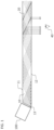
- FIG. 1 shows rays propagating inside a light-guide optical element (LOE) 10 (referred to herein interchangeably as a "waveguide”) by internal reflection at mutually-parallel first and second major external surfaces 11 and 12.
- LOE light-guide optical element
- the rays are coupled out towards an eye 40 of an observer by embedded partially reflective mirrors 20, that are obliquely angled to the major external surfaces of the LOE.
- the invention is equally applicable to displays employing diffractive optical elements for coupling-out image illumination towards the eye of the observer, as is well-known in the art.
- Illumination from a projector 100 corresponding to a collimated image is here shown injected into the waveguide at surface 13 in a simple manner that does not duplicate the injected image, and therefore a conjugated image is not generated.
- the rays propagating inside the waveguide contain 'holes', i.e., regions which the image illumination does not reach, and the rays reaching the observer's eye 40 are not uniform.
- the intensity distribution detected by the observer is therefore not uniform, and would change with different positions of the eye within an "eye motion box" (permissible viewing positions of the eye), and would depend on the specific field being observed.
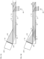
- FIGS. 2A and 2B In order to achieve uniform illumination of the outcoupled light, more advanced coupling-in configurations are often used, such as the one presented in FIGS. 2A and 2B .
- a projector 100 provides a larger aperture and is coupled to the LOE via a prism 30 so that rays injected into the waveguide and reflected by the lower surface of the waveguide 12 overlap rays that are injected directly from the projector. This assures that both the image and its conjugate are fully present inside the waveguide, referred to as "filling" the waveguide with the image illumination. Of course, this must be true for all fields supported by the waveguide.
- 2A and 2B show the two extreme cases of a typical field of view, of about 20° wide inside the media, corresponding to about 30° wide in air. It will be noted that a significant proportion of the illumination for each field is lost (represented by ray directions which terminate at the back surface of the coupling prism rather than entering the LOE, due to falling outside the LOE aperture).
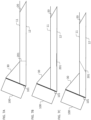
- an optical system including a light-guide optical element (LOE) 10 formed from transparent material and having mutually-parallel first and second major external surfaces 11, 12 for guiding light by internal reflection.
- a projector 100 is configured to project illumination corresponding to a collimated image from an aperture 101, the illumination exiting the aperture with a chief ray defining an optical axis 102 of the projector and with an angular field about the chief ray.
- FIG. 3B illustrates a set of rays parallel to the chief ray
- FIGS. 3A and 3C illustrate the shallowest-angle and steepest-angle rays of the angular field, respectively.
- image injection surface 32 is provided in part by coupling prism 30 and in part by an edge of LOE 10, polished together to form a continuous surface.
- Projector 100 is associated with image injection surface 32 and oriented such that the chief ray and the angular field about the chief ray are injected through the image injection surface at angles of incidence relative to the major external surfaces that are greater than a critical angle for internal reflection at the major external surfaces.
- the orientation of the projector and coupling prism are such that the image illumination can propagate within the LOE by internal reflection at the angles at which they were projected.
- a reflective polarizing beam splitter 51 is deployed at an interface between the first major external surface 11 and the coupling prism 30, parallel to the major external surfaces. At least part of the illumination from projector 100 is incident on beam splitter 51 with a first polarization that is transmitted by the beam splitter from coupling prism 30 into LOE 10, while light corresponding to a conjugate image of the collimated image and having a second polarization is incident on the beam splitter from within the LOE and is reflected from the beam splitter so as to propagate within the LOE by internal reflection.
- the beam splitter thus differentiates between image illumination from projector 100, which is allowed to enter the LOE, and image illumination already within the LOE, which is prevented from escaping, and begins its propagation via internal reflection along the LOE.
- a waveplate is deployed in a path of at least a part of the image illumination to convert the illumination between the first polarization and the second polarization.
- FIGS. 3A-3C illustrate one example of this, in which the waveplate is implemented as a quarter-wave plate 52 associated with at least part of the second major external surface 12 of the LOE.
- Figure 4 presents a plot of reflectivity and transmissivity of s and p polarizations (respectively) as a function of incident angle, describing a typical coating layer for surface 51, as is known in the field of polarizing beam splitters.
- a suitable effect may be achieved using a wire grid polarizer.
- the retarder 52 would be a quarter waveplate, such that the polarization of light transmitted by the retarder back and forth would rotate, and would be converted from p-polarized to s-polarized light (or vice versa).
- rays projected by projector 100 are transmitted by beam splitter 51 and pass into the waveguide.
- the retarder 52 could be implemented in many ways, including but not limited to crystalline zero-order crystalline retarders, thin film polycrystalline true-zero-order retarders, subwavelength structures and advanced dielectric layers coated directly onto the waveguide.
- the system is implemented so that rays of all fields are reflected from surface 51 only once before reaching the end of the coupling prism. Otherwise, some loss of light will typically occur.
- the steeper-propagating rays may in some cases suffer from a non-uniform intensity profile. This may be mitigated in different ways, for instance, by using an embedded mixer element (namely, a partially reflected surface parallel to the major axes of the waveguide, described below with reference to FIGS. 8A and 8B ), or by placing closely-spaced coupling-out facets in the waveguide.
- the nonuniformity may be reduced or even eliminated by careful design of the projector aperture and geometry of the coupling configuration.
- Retarder 52 may be deployed only in the coupling-in region, or may extend over part or all of the waveguide.
- the retarder may also serve to rotate and mix the polarization along the waveguide, and mitigate any polarization artifacts that may arise, for instance, by the polarization-dependent coupling-in configuration of this embodiment.
- the retarder could be located on the external surface of the waveguide, or between the waveguide 10 and external thin cover-plates (not shown), which may be used to enhance uniformity of out-coupled illumination.
- trapping of light within the LOE by beam splitter 51 relatively close to the image injection surface provides advantages for design of image projector 100.
- the entrance aperture of the waveguide is preferably imaged by the projector optics (illumination optics plus collimating optics, not shown) to the illuminations stop of the projector.
- the effective aperture to the waveguide is at the end of the coupling prism, far from the image injection surface.
- 3A-3C and the subsequent examples herein provide an effective waveguide aperture that is much closer to the image injection surface 32, allowing the use of a generic projector design in which the illumination stop is imaged to the projector exit aperture and typically facilitating the use of a smaller overall size of the projector.
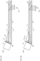
- FIGS. 5A and 5B show an alternative implementation of an embodiment of the invention where the image injection surface 32 is provided entirely by coupling prism 30, resulting in projector 100 being placed on top of the waveguide. Such a configuration would be significantly easier to manufacture, but results in a slightly larger aperture. In all other respects, the structure and operation of the implementation of FIGS. 5A and 5B are analogous to those of FIGS. 3A-3C .
- FIGS. 6A and 6B illustrate an alternative implementation which, instead of employing a retarder on the second major surface of the waveguide, employs a retarder 52 in the form of a half-wave plate deployed in overlapping relation to a first part of the aperture 101 without overlapping a second part of the aperture.
- the "first" part of the aperture projects illumination through a part of the image injection surface 32 from which light passes through beam splitter 51. This is suited to a case in which the projector projects a polarization which is reflected by the beam splitter.
- the polarization which is reflected by the beam splitter is introduced directly into the LOE in the lower part of the coupling-in surface, as shown, and is therefore trapped by the beam splitter and propagates by internal reflection along the LOE, while the half-wave plate 52 converts the illumination of the second polarization into illumination of the first polarization in the upper part of the aperture as shown, allowing that part of the image illumination to be transmitted by the beam splitter and to enter the LOE.
- the beam splitter passes p-polarization and reflects s-polarization
- the rays of the lower part of the image injection surface that are injected directly into the waveguide and that do not propagate through the retarder 51 are s-polarized
- the rays of the upper part of the image injection surface, that do propagate through the retarder 51, (which here preferably acts as a half waveplate) are injected into the waveguide at p-polarization.
- an equivalent effect can be achieved by using a projector which generates the polarization that is transmitted by the beam splitter, and deploying the half-wave plate 52 on the part of the image injection surface 32 through which light is coupled directly into the LOE without traversing the beam splitter (the lower part, in the orientation illustrated here).
- the beam splitter is described as being at an interface between the first major external surface 11 and the coupling prism 30, and parallel to the major external surfaces.
- the "interface” for this purpose is defined functionally as the region in which light passes from coupling prism 30 into LOE 10.
- the beam splitter is deployed coplanar with the first major external surface 11, typically either as a coating applied to one or other of the facing surfaces of coupling prism 30 into LOE 10 prior to bonding, or as a film or other layer sandwiched between the coupling prism 30 and LOE 10.
- deployment of the beam splitter embedded within coupling prism 30 or within LOE 10 would also be considered to be "at the interface” so long as it is sufficiently close to the interface to provide the functionality described above.
- parallelism of the beam splitter to the major surfaces of the LOE is essential in order to avoid generating ghost images as the image illumination propagates along the LOE.
- the various coupling-in arrangements described above inherently couple light into the waveguide in a mixed polarization state, i.e., with a superposition of p and s polarized light, such that for a certain field some regions of the input aperture are composed of p-polarized light and other regions of the input aperture are composed of s-polarized light. Since the embedded (refractive or diffractive) components that couple light out of the waveguide are typically polarization sensitive, this could potentially result in striped (non-uniform intensity) images at the output.
- the embedded elements could be designed and optimized to maximize uniformity by matching the conditions of both polarization states, but this is usually very difficult to achieve; and would come at the price of efficiency, color uniformity etc. Therefore, a number of alternative approaches are proposed below to ameliorate effects of the mixed-polarization illumination coupled into the waveguide.
- a polarization retarder 201 can be placed inside the waveguide so that it controls the polarization state of the light inside the waveguide.
- the retarder can be made from a birefringent crystal, from a thin layer of polymer or from a structural or spatially varying coating or spatially varying grating.
- Such an element can be embedded inside the waveguide (as described in coassigned PCT patent application no. PCT/IL2021/051143 ), or it can be bonded separately between the waveguide and the coupling-in wedge, if these are produced separately.
- the thickness of the retarder can be set to a preferred thickness.
- it can be thin, such that it would operate as a true quarter waveplate for the relevant wavelengths and considering the angle of incidence of all fields in the field of view (FOV), such that s and p polarized light transmitted by the retarder would be converted to (approximately) circularly polarized (but with opposite handedness).
- FOV field of view
- the projector 100 may be configured to generate circularly polarized image illumination, and the polarized beam splitter 51 can correspondingly be implemented as a circular-polarized beam splitter. In this manner, light coupled into the waveguide would be either right or left-handed circularly polarized, and the uniformity of the output light would be significantly improved.
- d ⁇ 0.1-1mm is sufficient for the retarder to provide a "depolarizing" effect. Specifically, different wavelengths within a given color spectral bandwidth are rotated to different polarization states, and the superposition of all wavelengths behaves effectively as unpolarized light.
- a thick retarder may cause unwanted artifacts in the configurations of FIGS. 7B and 7C , due to the different optical paths through the retarder that would generate ghost images. This can be resolved if the retarder is placed perpendicular to the waveguide with sufficient accuracy, as in FIG. 7A . In this case, the angular orientation of all rays propagating through the retarder is maintained, and no ghost images are expected.
- the projector outputs image illumination in a polarization state that is not orthogonal to the waveguide, i.e., not pure s or p polarized light according to the waveguide axes, but rather a linear superposition of the two, the polarization of each wavelength would rotate at each reflection of TIR on the major surfaces of the waveguide. This would effectively have a similar effect to the thick retarder in Fig. 7 .
- This mixing of the coating could be further enhanced by coating the major surfaces of the waveguide with a dedicated coating, as in patent WO2021105978A1 .
- FIGS. 8A and 8B Another approach could be to place a partially reflective layer 202 in the middle of the waveguide and parallel to the major external surfaces (as disclosed in PCT patent application publication no. WO 2021/079372 ), that would mix the light. Examples of such a structure are illustrated in FIGS. 8A and 8B . According to this option, the light of each field would be uniform throughout the waveguide, however the proportion of p and s polarized light might still vary from one field to another. This effect would need to be accounted for when designing the properties of the diffractive or refractive elements that are embedded inside the waveguide.
- projectors 100 may employ any suitable image-generating technology including, but not limited to, liquid crystal transmissive or reflective (LCOS) projectors, scanned-laser projectors or DLP projectors, all employing any suitable collimating optics.
- LCOS liquid crystal transmissive or reflective
Landscapes
- Physics & Mathematics (AREA)
- General Physics & Mathematics (AREA)
- Optics & Photonics (AREA)
- Optical Elements Other Than Lenses (AREA)
- Polarising Elements (AREA)
- Optical Couplings Of Light Guides (AREA)
- Diffracting Gratings Or Hologram Optical Elements (AREA)
- Light Guides In General And Applications Therefor (AREA)
Claims (8)
- Optisches System, umfassend:(a) ein optisches Lichtleiterelement (LOE), das aus einem transparenten Material hergestellt ist und eine erste und eine zweite Hauptaußenfläche, die zueinander parallel sind, aufweist, zum Leiten von Licht durch innere Reflexion;(b) einen Projektor, der dazu konfiguriert ist, eine Beleuchtung, die einem kollimierten Bild entspricht, aus einer Blende zu projizieren, wobei die Beleuchtung aus der Blende mit einem Hauptstrahl, der eine optische Achse des Projektors definiert, und mit einem Winkelbereich um den Hauptstrahl austritt;(c) ein Kopplungsprisma, das an der ersten Hauptaußenfläche des LOE angebracht ist, wobei das Kopplungsprisma mindestens einen Teil einer Bildeinspiegelungsfläche bereitstellt, die schräg zu den Hauptaußenflächen abgewinkelt ist, wobei der Projektor mit der Bildeinspiegelungsfläche assoziiert ist und derart ausgerichtet ist, dass der Hauptstrahl und der Winkelbereich um den Hauptstrahl durch die Bildeinspiegelungsfläche in Einfallswinkeln in Bezug auf die Hauptaußenflächen eingespiegelt werden, die größer als ein Grenzwinkel für innere Reflexion an den Hauptaußenflächen sind; und(d) ein reflektierender polarisierender Strahlteiler, der an einer Grenzfläche zwischen der Hauptaußenfläche und dem Kopplungsprisma parallel zu den Hauptaußenflächen eingesetzt wird, wobei mindestens ein Teil der Beleuchtung auf den Strahlteiler mit einer ersten Polarisation einfällt und von dem Strahlteiler aus dem Kopplungsprisma in das LOE übertragen wird, wobei Licht, das einem konjugierten Bild des kollimierten Bilds entspricht und eine zweite Polarisation aufweist und das auf den Strahlteiler aus dem Inneren des LOE einfällt, von dem Strahlteiler reflektiert wird, um sich durch innere Reflexion im Inneren des LOE auszubreiten.
- Optisches System nach Anspruch 1, weiterhin umfassend eine Verzögerungsplatte, die in einem Weg von mindestens einem Teil der Beleuchtung eingesetzt wird, um die Beleuchtung zwischen der ersten Polarisation und der zweiten Polarisation umzuwandeln.
- Optisches System nach Anspruch 2, wobei die Verzögerungsplatte eine λ/4-Verzögerungsplatte ist, die mit mindestens einem Teil der zweiten Hauptaußenfläche des LOE assoziiert ist.
- Optisches System nach Anspruch 2, wobei die Wellenplatte eine λ/2-Verzögerungsplatte ist, die in einer überlappenden Beziehung zu einem ersten Teil der Blende eingesetzt wird, ohne einen zweiten Teil der Blende zu überlappen.
- Optisches System nach Anspruch 4, wobei der erste Teil der Blende eine Beleuchtung durch einen Teil der Bildeinspiegelungsfläche projiziert, von der Licht in das LOE verläuft, ohne den Strahlteiler zu durchqueren.
- Optisches System nach Anspruch 4, wobei der Projektor dazu konfiguriert ist, eine Beleuchtung mit der zweiten Polarisation zu projizieren, wobei der erste Teil der Blende eine Beleuchtung durch einen Teil der Bildeinspiegelungsfläche projiziert, von der Licht durch den Strahlteiler verläuft, wobei die λ/2-Verzögerungsplatte eine Beleuchtung mit der zweiten Polarisation in eine Beleuchtung mit der ersten Polarisation umwandelt.
- Optisches System nach Anspruch 1, wobei die Bildeinspiegelungsfläche zum Teil von dem Kopplungsprisma und zum Teil von einer Fläche des LOE bereitgestellt wird.
- Optisches System nach Anspruch 1, wobei die Bildeinspiegelungsfläche vollständig von dem Kopplungsprisma bereitgestellt wird.
Priority Applications (1)
| Application Number | Priority Date | Filing Date | Title |
|---|---|---|---|
| EP24195574.9A EP4462172A3 (de) | 2021-03-01 | 2022-03-01 | Optisches system mit kompakter kopplung eines projektors in einen wellenleiter |
Applications Claiming Priority (2)
| Application Number | Priority Date | Filing Date | Title |
|---|---|---|---|
| US202163154870P | 2021-03-01 | 2021-03-01 | |
| PCT/IL2022/050226 WO2022185306A1 (en) | 2021-03-01 | 2022-03-01 | Optical system with compact coupling from a projector into a waveguide |
Related Child Applications (1)
| Application Number | Title | Priority Date | Filing Date |
|---|---|---|---|
| EP24195574.9A Division EP4462172A3 (de) | 2021-03-01 | 2022-03-01 | Optisches system mit kompakter kopplung eines projektors in einen wellenleiter |
Publications (3)
| Publication Number | Publication Date |
|---|---|
| EP4237903A1 EP4237903A1 (de) | 2023-09-06 |
| EP4237903A4 EP4237903A4 (de) | 2024-04-24 |
| EP4237903B1 true EP4237903B1 (de) | 2024-09-04 |
Family
ID=83154939
Family Applications (2)
| Application Number | Title | Priority Date | Filing Date |
|---|---|---|---|
| EP22762733.8A Active EP4237903B1 (de) | 2021-03-01 | 2022-03-01 | Optisches system mit kompakter kopplung eines projektors in einen wellenleiter |
| EP24195574.9A Pending EP4462172A3 (de) | 2021-03-01 | 2022-03-01 | Optisches system mit kompakter kopplung eines projektors in einen wellenleiter |
Family Applications After (1)
| Application Number | Title | Priority Date | Filing Date |
|---|---|---|---|
| EP24195574.9A Pending EP4462172A3 (de) | 2021-03-01 | 2022-03-01 | Optisches system mit kompakter kopplung eines projektors in einen wellenleiter |
Country Status (8)
| Country | Link |
|---|---|
| US (2) | US11860369B2 (de) |
| EP (2) | EP4237903B1 (de) |
| JP (2) | JP7698342B2 (de) |
| KR (1) | KR20230148324A (de) |
| CN (2) | CN116635773B (de) |
| IL (2) | IL305555B2 (de) |
| TW (1) | TW202244552A (de) |
| WO (1) | WO2022185306A1 (de) |
Families Citing this family (7)
| Publication number | Priority date | Publication date | Assignee | Title |
|---|---|---|---|---|
| EP4237903B1 (de) * | 2021-03-01 | 2024-09-04 | Lumus Ltd. | Optisches system mit kompakter kopplung eines projektors in einen wellenleiter |
| IL313871A (en) | 2022-01-07 | 2024-08-01 | Lumus Ltd | Optical system for image orientation for viewing |
| EP4569263A1 (de) * | 2022-09-15 | 2025-06-18 | Google LLC | Entendue-auspressung in optischen systemen |
| CN116047649B (zh) * | 2023-01-31 | 2024-03-12 | 上海理湃光晶技术有限公司 | 一种几何光波导耦合装置和近眼显示设备 |
| EP4602414A4 (de) * | 2023-05-30 | 2026-01-07 | Lumus Ltd | Optischer wellenleiter mit blende |
| WO2025080449A1 (en) * | 2023-10-09 | 2025-04-17 | Meta Platforms Technologies, Llc | Layered kaleido geometric waveguide |
| WO2025257601A1 (en) * | 2024-06-13 | 2025-12-18 | Creal Sa | Near-eye light field system and wearable device comprising the near-eye light field system |
Family Cites Families (323)
| Publication number | Priority date | Publication date | Assignee | Title |
|---|---|---|---|---|
| US2748659A (en) | 1951-02-26 | 1956-06-05 | Jenaer Glaswerk Schott & Gen | Light source, searchlight or the like for polarized light |
| US2886911A (en) | 1953-07-23 | 1959-05-19 | George K C Hardesty | Duo-panel edge illumination system |
| US2795069A (en) | 1956-02-07 | 1957-06-11 | George K C Hardesty | Laminated metal-plastic illuminable panel |
| US3491245A (en) | 1967-04-10 | 1970-01-20 | George K C Hardesty | Guided light display panel |
| DE2057827A1 (de) | 1969-11-24 | 1971-06-03 | Vickers Ltd | Optische Anordnung zur Bildfeldebnung |
| US3626394A (en) | 1970-04-09 | 1971-12-07 | Magnavox Co | Magneto-optical system |
| US3667621A (en) | 1970-10-20 | 1972-06-06 | Wisconsin Foundry And Machine | Fluid power system for a self-contained unloading unit |
| US3737212A (en) | 1970-12-14 | 1973-06-05 | Gen Electric | Diffraction optics head up display |
| GB1377627A (en) | 1971-09-01 | 1974-12-18 | Rank Organisation Ltd | Beam splitting prisms |
| US3857109A (en) | 1973-11-21 | 1974-12-24 | Us Navy | Longitudinally-pumped two-wavelength lasers |
| US3873209A (en) | 1973-12-10 | 1975-03-25 | Bell Telephone Labor Inc | Measurement of thin films by optical waveguiding technique |
| FR2295436A1 (fr) | 1974-12-16 | 1976-07-16 | Radiotechnique Compelec | Dispositif coupleur directif pour fibres optiques multimodes |
| US3940204A (en) | 1975-01-23 | 1976-02-24 | Hughes Aircraft Company | Optical display systems utilizing holographic lenses |
| US3969023A (en) | 1975-03-06 | 1976-07-13 | American Optical Corporation | Method and apparatus for detecting layers of stress in lenses |
| US4084883A (en) | 1977-02-28 | 1978-04-18 | The University Of Rochester | Reflective polarization retarder and laser apparatus utilizing same |
| DE3000402A1 (de) | 1979-01-19 | 1980-07-31 | Smiths Industries Ltd | Anzeigevorrichtung |
| US4355864A (en) | 1980-03-26 | 1982-10-26 | Sperry Corporation | Magnetooptic switching devices |
| US4331387A (en) | 1980-07-03 | 1982-05-25 | Westinghouse Electric Corp. | Electro-optical modulator for randomly polarized light |
| DE3266408D1 (en) | 1981-10-14 | 1985-10-24 | Gec Avionics | Optical arrangements for head-up displays and night vision goggles |
| US4516828A (en) | 1982-05-03 | 1985-05-14 | General Motors Corporation | Duplex communication on a single optical fiber |
| FR2562273B1 (fr) | 1984-03-27 | 1986-08-08 | France Etat Armement | Dispositif d'observation a travers une paroi dans deux directions opposees |
| US4715684A (en) | 1984-06-20 | 1987-12-29 | Hughes Aircraft Company | Optical system for three color liquid crystal light valve image projection system |
| JPS61140925A (ja) | 1984-12-13 | 1986-06-28 | Olympus Optical Co Ltd | 複屈折の温度補正液晶レンズ |
| US4711512A (en) | 1985-07-12 | 1987-12-08 | Environmental Research Institute Of Michigan | Compact head-up display |
| US4805988A (en) | 1987-07-24 | 1989-02-21 | Nelson Dones | Personal video viewing device |
| US4798448A (en) | 1988-02-16 | 1989-01-17 | General Electric Company | High efficiency illumination system for display devices |
| US4932743A (en) | 1988-04-18 | 1990-06-12 | Ricoh Company, Ltd. | Optical waveguide device |
| DE68909553T2 (de) | 1988-10-21 | 1994-01-27 | Thomson Csf | Optisches Kollimationssystem für eine Helmsichtanzeige. |
| CN1043203A (zh) | 1988-12-02 | 1990-06-20 | 三井石油化学工业株式会社 | 光输出控制方法及其装置 |
| US4978952A (en) | 1989-02-24 | 1990-12-18 | Collimated Displays Incorporated | Flat screen color video display |
| FR2647556B1 (fr) | 1989-05-23 | 1993-10-29 | Thomson Csf | Dispositif optique pour l'introduction d'une image collimatee dans le champ visuel d'un observateur et casque comportant au moins un tel dispositif |
| US5157526A (en) | 1990-07-06 | 1992-10-20 | Hitachi, Ltd. | Unabsorbing type polarizer, method for manufacturing the same, polarized light source using the same, and apparatus for liquid crystal display using the same |
| US5096520A (en) | 1990-08-01 | 1992-03-17 | Faris Sades M | Method for producing high efficiency polarizing filters |
| US5751480A (en) | 1991-04-09 | 1998-05-12 | Canon Kabushiki Kaisha | Plate-like polarizing element, a polarizing conversion unit provided with the element, and a projector provided with the unit |
| FR2683918B1 (fr) | 1991-11-19 | 1994-09-09 | Thomson Csf | Materiau constitutif d'une lunette de visee et arme utilisant cette lunette. |
| US5367399A (en) | 1992-02-13 | 1994-11-22 | Holotek Ltd. | Rotationally symmetric dual reflection optical beam scanner and system using same |
| US5301067A (en) | 1992-05-06 | 1994-04-05 | Plx Inc. | High accuracy periscope assembly |
| US5231642A (en) | 1992-05-08 | 1993-07-27 | Spectra Diode Laboratories, Inc. | Semiconductor ring and folded cavity lasers |
| US5369415A (en) | 1992-06-29 | 1994-11-29 | Motorola, Inc. | Direct retinal scan display with planar imager |
| US5680209A (en) | 1992-08-13 | 1997-10-21 | Maechler; Meinrad | Spectroscopic systems for the analysis of small and very small quantities of substances |
| US6144347A (en) | 1992-10-09 | 2000-11-07 | Sony Corporation | Head-mounted image display apparatus |
| US5537173A (en) | 1992-10-23 | 1996-07-16 | Olympus Optical Co., Ltd. | Film winding detecting means for a camera including control means for controlling proper and accurate winding and rewinding of a film |
| WO1994019712A1 (en) | 1993-02-26 | 1994-09-01 | Yeda Research & Development Co., Ltd. | Holographic optical devices |
| US7310072B2 (en) | 1993-10-22 | 2007-12-18 | Kopin Corporation | Portable communication display device |
| US5555329A (en) | 1993-11-05 | 1996-09-10 | Alliesignal Inc. | Light directing optical structure |
| JPH07199236A (ja) | 1993-12-28 | 1995-08-04 | Fujitsu Ltd | 光スイッチ及び光分配器 |
| US7262919B1 (en) | 1994-06-13 | 2007-08-28 | Canon Kabushiki Kaisha | Head-up display device with curved optical surface having total reflection |
| JPH08114765A (ja) | 1994-10-15 | 1996-05-07 | Fujitsu Ltd | 偏光分離・変換素子並びにこれを用いた偏光照明装置及び投射型表示装置 |
| US5650873A (en) | 1995-01-30 | 1997-07-22 | Lockheed Missiles & Space Company, Inc. | Micropolarization apparatus |
| JPH08201805A (ja) | 1995-01-31 | 1996-08-09 | Minolta Co Ltd | 液晶表示面の照明構造 |
| GB9521210D0 (en) | 1995-10-17 | 1996-08-28 | Barr & Stroud Ltd | Display system |
| US5870159A (en) | 1995-10-30 | 1999-02-09 | Kaj | Switchable achromatic polarization rotator |
| US6404550B1 (en) | 1996-07-25 | 2002-06-11 | Seiko Epson Corporation | Optical element suitable for projection display apparatus |
| US5829854A (en) | 1996-09-26 | 1998-11-03 | Raychem Corporation | Angled color dispersement and recombination prism |
| US6204974B1 (en) | 1996-10-08 | 2001-03-20 | The Microoptical Corporation | Compact image display system for eyeglasses or other head-borne frames |
| JPH10133055A (ja) | 1996-10-31 | 1998-05-22 | Sharp Corp | 光結合器及びその製造方法 |
| US5919601A (en) | 1996-11-12 | 1999-07-06 | Kodak Polychrome Graphics, Llc | Radiation-sensitive compositions and printing plates |
| US6577411B1 (en) | 1996-11-12 | 2003-06-10 | Planop-Planar Optics Ltd. | Optical system for alternative or simultaneous direction of light originating from two scenes to the eye of a viewer |
| US5724163A (en) | 1996-11-12 | 1998-03-03 | Yariv Ben-Yehuda | Optical system for alternative or simultaneous direction of light originating from two scenes to the eye of a viewer |
| JPH10160961A (ja) | 1996-12-03 | 1998-06-19 | Mitsubishi Gas Chem Co Inc | 光学素子 |
| US6292296B1 (en) | 1997-05-28 | 2001-09-18 | Lg. Philips Lcd Co., Ltd. | Large scale polarizer and polarizer system employing it |
| US5883684A (en) | 1997-06-19 | 1999-03-16 | Three-Five Systems, Inc. | Diffusively reflecting shield optically, coupled to backlit lightguide, containing LED's completely surrounded by the shield |
| US5896232A (en) | 1997-08-07 | 1999-04-20 | International Business Machines Corporation | Highly efficient and compact frontlighting for polarization-based reflection light valves |
| RU2124746C1 (ru) | 1997-08-11 | 1999-01-10 | Закрытое акционерное общество "Кванта Инвест" | Дихроичный поляризатор |
| US6091548A (en) | 1997-10-01 | 2000-07-18 | Raytheon Company | Optical system with two-stage aberration correction |
| CA2307877C (en) | 1997-10-30 | 2005-08-30 | The Microoptical Corporation | Eyeglass interface system |
| ATE254291T1 (de) | 1998-04-02 | 2003-11-15 | Elop Electrooptics Ind Ltd | Optische holographische vorrichtungen |
| US6231992B1 (en) | 1998-09-04 | 2001-05-15 | Yazaki Corporation | Partial reflector |
| JP2000155234A (ja) | 1998-11-24 | 2000-06-06 | Nippon Electric Glass Co Ltd | 光ファイバ用毛細管 |
| JP2000187177A (ja) | 1998-12-22 | 2000-07-04 | Olympus Optical Co Ltd | 画像表示装置 |
| US6798579B2 (en) | 1999-04-27 | 2004-09-28 | Optical Products Development Corp. | Real imaging system with reduced ghost imaging |
| US6728034B1 (en) | 1999-06-16 | 2004-04-27 | Matsushita Electric Industrial Co., Ltd. | Diffractive optical element that polarizes light and an optical pickup using the same |
| US20030063042A1 (en) | 1999-07-29 | 2003-04-03 | Asher A. Friesem | Electronic utility devices incorporating a compact virtual image display |
| WO2001027685A2 (en) | 1999-10-14 | 2001-04-19 | Stratos Product Development Company Llc | Virtual imaging system |
| JP2001141924A (ja) | 1999-11-16 | 2001-05-25 | Matsushita Electric Ind Co Ltd | 分波素子及び分波受光素子 |
| JP3828328B2 (ja) | 1999-12-28 | 2006-10-04 | ローム株式会社 | ヘッドマウントディスプレー |
| US6421148B2 (en) | 2000-01-07 | 2002-07-16 | Honeywell International Inc. | Volume holographic diffusers |
| US6362861B1 (en) | 2000-05-02 | 2002-03-26 | Agilent Technologies, Inc. | Microdisplay system |
| DE60142516D1 (de) | 2000-06-05 | 2010-08-19 | Lumus Ltd | Optischer strahlaufweiter mit substratlichtwellenleitung |
| US6324330B1 (en) | 2000-07-10 | 2001-11-27 | Ultratech Stepper, Inc. | Folded light tunnel apparatus and method |
| US6799859B1 (en) | 2000-07-24 | 2004-10-05 | Mitsubishi Rayon Co., Ltd. | Surface illuminant device and prism sheet used therefor |
| KR100388819B1 (ko) | 2000-07-31 | 2003-06-25 | 주식회사 대양이앤씨 | 헤드 마운트 디스플레이용 광학 시스템 |
| US6490104B1 (en) | 2000-09-15 | 2002-12-03 | Three-Five Systems, Inc. | Illumination system for a micro display |
| US6542307B2 (en) | 2000-10-20 | 2003-04-01 | Three-Five Systems, Inc. | Compact near-eye illumination system |
| JP4772204B2 (ja) | 2001-04-13 | 2011-09-14 | オリンパス株式会社 | 観察光学系 |
| KR100813943B1 (ko) | 2001-04-30 | 2008-03-14 | 삼성전자주식회사 | 복합 반사프리즘 및 이를 채용한 광픽업장치 |
| US6690513B2 (en) | 2001-07-03 | 2004-02-10 | Jds Uniphase Corporation | Rhomb interleaver |
| US6791760B2 (en) | 2001-07-24 | 2004-09-14 | Itt Manufacturing Enterprises, Inc. | Planar diffractive relay |
| US6927694B1 (en) | 2001-08-20 | 2005-08-09 | Research Foundation Of The University Of Central Florida | Algorithm for monitoring head/eye motion for driver alertness with one camera |
| US6556282B2 (en) | 2001-09-04 | 2003-04-29 | Rosemount Aerospace, Inc. | Combined LOAS and LIDAR system |
| WO2003023756A1 (en) | 2001-09-07 | 2003-03-20 | The Microoptical Corporation | Light weight, compact, remountable face-supported electronic display |
| DE10150656C2 (de) | 2001-10-13 | 2003-10-02 | Schott Glas | Reflektor für eine Hochdruck-Gasentladungslampe |
| US6775432B2 (en) | 2001-10-19 | 2004-08-10 | Santanu Basu | Method and apparatus for optical wavelength demultiplexing, multiplexing and routing |
| JP2003140081A (ja) | 2001-11-06 | 2003-05-14 | Nikon Corp | ホログラムコンバイナ光学系 |
| FR2834799B1 (fr) | 2002-01-11 | 2004-04-16 | Essilor Int | Lentille ophtalmique presentant un insert de projection |
| HRP20020044B1 (en) | 2002-01-16 | 2008-11-30 | Mara-Institut D.O.O. | Indirectly prestressed, concrete, roof-ceiling construction with flat soffit |
| IL148804A (en) | 2002-03-21 | 2007-02-11 | Yaacov Amitai | Optical device |
| DE10216169A1 (de) | 2002-04-12 | 2003-10-30 | Zeiss Carl Jena Gmbh | Anordnung zur Polarisation von Licht |
| US20070165192A1 (en) | 2006-01-13 | 2007-07-19 | Silicon Optix Inc. | Reduced field angle projection display system |
| ITTO20020625A1 (it) | 2002-07-17 | 2004-01-19 | Fiat Ricerche | Guida di luce per dispositivi di visualizzazione di tipo "head-mounted" o "head-up" |
| EP1418459A1 (de) | 2002-11-08 | 2004-05-12 | 3M Innovative Properties Company | Optisches Element mit kuboktaedrischem Polyeder als Strahlteiler oder Lichtstreuer |
| US20050174641A1 (en) | 2002-11-26 | 2005-08-11 | Jds Uniphase Corporation | Polarization conversion light integrator |
| US7175304B2 (en) | 2003-01-30 | 2007-02-13 | Touchsensor Technologies, Llc | Integrated low profile display |
| US7205960B2 (en) | 2003-02-19 | 2007-04-17 | Mirage Innovations Ltd. | Chromatic planar optic display system |
| US7196849B2 (en) | 2003-05-22 | 2007-03-27 | Optical Research Associates | Apparatus and methods for illuminating optical systems |
| IL157836A (en) | 2003-09-10 | 2009-08-03 | Yaakov Amitai | Optical devices particularly for remote viewing applications |
| IL157837A (en) | 2003-09-10 | 2012-12-31 | Yaakov Amitai | Substrate-guided optical device particularly for three-dimensional displays |
| IL157838A (en) | 2003-09-10 | 2013-05-30 | Yaakov Amitai | High-brightness optical device |
| KR20050037085A (ko) | 2003-10-17 | 2005-04-21 | 삼성전자주식회사 | 광터널, 균일광 조명장치 및 이를 채용한 프로젝터 |
| US7430355B2 (en) | 2003-12-08 | 2008-09-30 | University Of Cincinnati | Light emissive signage devices based on lightwave coupling |
| US7101063B2 (en) | 2004-02-05 | 2006-09-05 | Hewlett-Packard Development Company, L.P. | Systems and methods for integrating light |
| JP4218553B2 (ja) | 2004-03-08 | 2009-02-04 | ソニー株式会社 | 画像表示装置 |
| JP2005308717A (ja) | 2004-03-23 | 2005-11-04 | Shin Etsu Chem Co Ltd | 光ファイバ母材のコア部非円率の測定方法及びその装置 |
| EP1731943B1 (de) | 2004-03-29 | 2019-02-13 | Sony Corporation | Optische einrichtung und virtuelle bildanzeigeeinrichtung |
| JP4373286B2 (ja) | 2004-05-06 | 2009-11-25 | オリンパス株式会社 | 頭部装着型表示装置 |
| EP1748305A4 (de) | 2004-05-17 | 2009-01-14 | Nikon Corp | Optisches element, optisches kombinierersystem und bildanzeigeeinheit |
| TWI282017B (en) | 2004-05-28 | 2007-06-01 | Epistar Corp | Planar light device |
| IL162573A (en) | 2004-06-17 | 2013-05-30 | Lumus Ltd | Optical component in a large key conductive substrate |
| IL162572A (en) | 2004-06-17 | 2013-02-28 | Lumus Ltd | High brightness optical device |
| US8035872B2 (en) | 2004-06-29 | 2011-10-11 | Nikon Corporation | Image combiner and image display device |
| US7667962B2 (en) | 2004-08-20 | 2010-02-23 | Mullen Jeffrey D | Wireless devices with flexible monitors and keyboards |
| US20060052146A1 (en) | 2004-09-09 | 2006-03-09 | Shu-Fong Ou | Heated mounted display device with mobile phone functions |
| US20060103590A1 (en) | 2004-10-21 | 2006-05-18 | Avner Divon | Augmented display system and methods |
| US7778508B2 (en) | 2004-12-06 | 2010-08-17 | Nikon Corporation | Image display optical system, image display unit, illuminating optical system, and liquid crystal display unit |
| US20060126181A1 (en) | 2004-12-13 | 2006-06-15 | Nokia Corporation | Method and system for beam expansion in a display device |
| WO2006085310A1 (en) | 2005-02-10 | 2006-08-17 | Lumus Ltd. | Substrate-guided optical device particularly for vision enhanced optical systems |
| US10073264B2 (en) | 2007-08-03 | 2018-09-11 | Lumus Ltd. | Substrate-guide optical device |
| IL166799A (en) | 2005-02-10 | 2014-09-30 | Lumus Ltd | Aluminum shale surfaces for use in a conductive substrate |
| US7724443B2 (en) | 2005-02-10 | 2010-05-25 | Lumus Ltd. | Substrate-guided optical device utilizing thin transparent layer |
| EP1848966A1 (de) | 2005-02-17 | 2007-10-31 | Lumus Ltd | System zur persönlichen navigation |
| US7405881B2 (en) | 2005-05-30 | 2008-07-29 | Konica Minolta Holdings, Inc. | Image display apparatus and head mount display |
| US8718437B2 (en) | 2006-03-07 | 2014-05-06 | Qd Vision, Inc. | Compositions, optical component, system including an optical component, devices, and other products |
| JP4655771B2 (ja) | 2005-06-17 | 2011-03-23 | ソニー株式会社 | 光学装置及び虚像表示装置 |
| US20070002191A1 (en) | 2005-07-01 | 2007-01-04 | Seiko Epson Corporation | Projector |
| US20070007157A1 (en) | 2005-07-05 | 2007-01-11 | Buschmann Jeffrey P | Bottle-pack for light bulb |
| JP5030134B2 (ja) | 2005-08-18 | 2012-09-19 | 株式会社リコー | 偏光変換素子、偏光変換光学系および画像投影装置 |
| EP1922579B1 (de) | 2005-09-07 | 2015-08-19 | BAE Systems PLC | Projektionsanzeige mit zwei plattenartigen coplanaren, gitter enthaltenden wellenleitern |
| IL171820A (en) | 2005-11-08 | 2014-04-30 | Lumus Ltd | A polarizing optical component for light coupling within a conductive substrate |
| US10048499B2 (en) | 2005-11-08 | 2018-08-14 | Lumus Ltd. | Polarizing optical system |
| WO2007062098A2 (en) | 2005-11-21 | 2007-05-31 | Microvision, Inc. | Display with image-guiding substrate |
| IL173715A0 (en) * | 2006-02-14 | 2007-03-08 | Lumus Ltd | Substrate-guided imaging lens |
| JP2007219106A (ja) | 2006-02-16 | 2007-08-30 | Konica Minolta Holdings Inc | 光束径拡大光学素子、映像表示装置およびヘッドマウントディスプレイ |
| IL174170A (en) | 2006-03-08 | 2015-02-26 | Abraham Aharoni | Device and method for two-eyed tuning |
| IL177618A (en) | 2006-08-22 | 2015-02-26 | Lumus Ltd | Optical component in conductive substrate |
| US7826113B2 (en) | 2007-03-28 | 2010-11-02 | Konica Minolta Holdings, Inc. | Joined optical member, image display apparatus, and head-mounted display |
| EP2142953B1 (de) | 2007-04-22 | 2019-06-05 | Lumus Ltd | Collimierende optische anordnung und system |
| US8139944B2 (en) | 2007-05-08 | 2012-03-20 | The Boeing Company | Method and apparatus for clearing an optical channel |
| IL183637A (en) | 2007-06-04 | 2013-06-27 | Zvi Lapidot | Head display system |
| US7589901B2 (en) | 2007-07-10 | 2009-09-15 | Microvision, Inc. | Substrate-guided relays for use with scanned beam light sources |
| US8433199B2 (en) | 2008-03-18 | 2013-04-30 | Princeton University | System and method for nonlinear self-filtering via dynamical stochastic resonance |
| US8369019B2 (en) | 2008-04-14 | 2013-02-05 | Bae Systems Plc | Waveguides |
| EP2332195A2 (de) | 2008-08-19 | 2011-06-15 | Plextronics, Inc. | Beleuchtungsanordnungen mit organischen leuchtdioden |
| JP2010050064A (ja) * | 2008-08-25 | 2010-03-04 | Citizen Electronics Co Ltd | 導光板、面状ライトユニット及び表示装置並びに導光板の製造方法 |
| US7949214B2 (en) | 2008-11-06 | 2011-05-24 | Microvision, Inc. | Substrate guided relay with pupil expanding input coupler |
| JPWO2010061835A1 (ja) | 2008-11-26 | 2012-04-26 | コニカミノルタオプト株式会社 | 映像表示装置およびヘッドマウントディスプレイ |
| US8317352B2 (en) | 2008-12-11 | 2012-11-27 | Robert Saccomanno | Non-invasive injection of light into a transparent substrate, such as a window pane through its face |
| WO2010067114A1 (en) | 2008-12-12 | 2010-06-17 | Bae Systems Plc | Improvements in or relating to waveguides |
| JP5251671B2 (ja) * | 2009-03-30 | 2013-07-31 | セイコーエプソン株式会社 | 積層1/2波長板、光ピックアップ装置、偏光変換素子、及び投写型表示装置 |
| US8873912B2 (en) | 2009-04-08 | 2014-10-28 | International Business Machines Corporation | Optical waveguide with embedded light-reflecting feature and method for fabricating the same |
| WO2010123934A1 (en) | 2009-04-20 | 2010-10-28 | The Arizona Board Of Regents On Behalf Of The University Of Arizona | Optical see-through free-form head-mounted display |
| WO2010124028A2 (en) | 2009-04-21 | 2010-10-28 | Vasylyev Sergiy V | Light collection and illumination systems employing planar waveguide |
| US9335604B2 (en) | 2013-12-11 | 2016-05-10 | Milan Momcilo Popovich | Holographic waveguide display |
| US20100291489A1 (en) | 2009-05-15 | 2010-11-18 | Api Nanofabrication And Research Corp. | Exposure methods for forming patterned layers and apparatus for performing the same |
| US20120249797A1 (en) | 2010-02-28 | 2012-10-04 | Osterhout Group, Inc. | Head-worn adaptive display |
| JP2011199672A (ja) | 2010-03-19 | 2011-10-06 | Seiko Instruments Inc | ガラス基板の接合方法、ガラス接合体、パッケージの製造方法、パッケージ、圧電振動子、発振器、電子機器及び電波時計 |
| US9028123B2 (en) | 2010-04-16 | 2015-05-12 | Flex Lighting Ii, Llc | Display illumination device with a film-based lightguide having stacked incident surfaces |
| US8649099B2 (en) | 2010-09-13 | 2014-02-11 | Vuzix Corporation | Prismatic multiple waveguide for near-eye display |
| US9632315B2 (en) | 2010-10-21 | 2017-04-25 | Lockheed Martin Corporation | Head-mounted display apparatus employing one or more fresnel lenses |
| US8743464B1 (en) | 2010-11-03 | 2014-06-03 | Google Inc. | Waveguide with embedded mirrors |
| US8666208B1 (en) | 2010-11-05 | 2014-03-04 | Google Inc. | Moldable waveguide with embedded micro structures |
| US9292973B2 (en) | 2010-11-08 | 2016-03-22 | Microsoft Technology Licensing, Llc | Automatic variable virtual focus for augmented reality displays |
| US9304319B2 (en) | 2010-11-18 | 2016-04-05 | Microsoft Technology Licensing, Llc | Automatic focus improvement for augmented reality displays |
| JP2012123936A (ja) | 2010-12-06 | 2012-06-28 | Omron Corp | 面光源装置及び立体表示装置 |
| JP5645631B2 (ja) | 2010-12-13 | 2014-12-24 | 三菱電機株式会社 | 波長モニタ、光モジュールおよび波長モニタ方法 |
| US9348143B2 (en) | 2010-12-24 | 2016-05-24 | Magic Leap, Inc. | Ergonomic head mounted display device and optical system |
| US8939579B2 (en) | 2011-01-28 | 2015-01-27 | Light Prescriptions Innovators, Llc | Autofocusing eyewear, especially for presbyopia correction |
| JP2012252091A (ja) | 2011-06-01 | 2012-12-20 | Sony Corp | 表示装置 |
| DE112012002688B4 (de) | 2011-06-28 | 2021-08-12 | Federal-Mogul Ignition LLC (n. d. Ges. d. Staates Delaware) | Zündkerze und Verfahren zur deren Herstellung |
| TW201302600A (zh) | 2011-07-04 | 2013-01-16 | Univ Nat Taiwan Science Tech | 矽奈米線陣列之製作方法 |
| US8639073B2 (en) | 2011-07-19 | 2014-01-28 | Teraxion Inc. | Fiber coupling technique on a waveguide |
| US8760762B1 (en) | 2011-08-12 | 2014-06-24 | Google Inc. | Image waveguide utilizing two mirrored or polarized surfaces |
| US9170425B1 (en) | 2011-08-17 | 2015-10-27 | Lockheed Martin Corporation | Multi-focal augmented reality lenses |
| US8917453B2 (en) | 2011-12-23 | 2014-12-23 | Microsoft Corporation | Reflective array waveguide |
| CN105433451A (zh) | 2011-12-23 | 2016-03-30 | 维珍妮国际(集团)有限公司 | 罩杯组件和包含这种罩杯的胸罩 |
| US10030846B2 (en) | 2012-02-14 | 2018-07-24 | Svv Technology Innovations, Inc. | Face-lit waveguide illumination systems |
| US8665178B1 (en) | 2012-03-01 | 2014-03-04 | Google, Inc. | Partially-reflective waveguide stack and heads-up display using same |
| US8736963B2 (en) | 2012-03-21 | 2014-05-27 | Microsoft Corporation | Two-dimensional exit-pupil expansion |
| JP5960799B2 (ja) | 2012-03-28 | 2016-08-02 | パイオニア株式会社 | ヘッドマウントディスプレイ及び表示方法 |
| US20130257832A1 (en) | 2012-03-30 | 2013-10-03 | Exelis, Inc. | Image pickoff apparatus system and method |
| DE102012208113A1 (de) | 2012-05-15 | 2013-11-21 | Robert Bosch Gmbh | Lasermodul mit duochromatischer Laserdiode für einen tragbaren Bildprojektor |
| IL219907A (en) | 2012-05-21 | 2017-08-31 | Lumus Ltd | Integrated head display system with eye tracking |
| US20130321432A1 (en) | 2012-06-01 | 2013-12-05 | QUALCOMM MEMES Technologies, Inc. | Light guide with embedded fresnel reflectors |
| EP4130820B1 (de) | 2012-06-11 | 2024-10-16 | Magic Leap, Inc. | Dreidimensionale anzeige mit mehreren tiefenebenen mit einem wellenleiterreflektorarrayprojektor |
| US9671566B2 (en) | 2012-06-11 | 2017-06-06 | Magic Leap, Inc. | Planar waveguide apparatus with diffraction element(s) and system employing same |
| US8913324B2 (en) | 2012-08-07 | 2014-12-16 | Nokia Corporation | Display illumination light guide |
| CA2884663A1 (en) | 2012-09-11 | 2014-03-20 | Magic Leap, Inc. | Ergonomic head mounted display device and optical system |
| US9933684B2 (en) | 2012-11-16 | 2018-04-03 | Rockwell Collins, Inc. | Transparent waveguide display providing upper and lower fields of view having a specific light output aperture configuration |
| US10119816B2 (en) * | 2012-11-21 | 2018-11-06 | Nikon Metrology Nv | Low drift reference for laser radar |
| FR2999301B1 (fr) | 2012-12-12 | 2015-01-09 | Thales Sa | Guide optique d'images collimatees a dedoubleur de faisceaux optiques et dispositif optique associe |
| JP6243353B2 (ja) | 2012-12-28 | 2017-12-06 | 株式会社nittoh | 投射光学系およびプロジェクタ装置 |
| US8947783B2 (en) | 2013-01-02 | 2015-02-03 | Google Inc. | Optical combiner for near-eye display |
| JP6065630B2 (ja) | 2013-02-13 | 2017-01-25 | セイコーエプソン株式会社 | 虚像表示装置 |
| WO2014188149A1 (en) | 2013-05-20 | 2014-11-27 | Milan Momcilo Popovich | Holographic waveguide eye tracker |
| US8913865B1 (en) | 2013-06-27 | 2014-12-16 | Microsoft Corporation | Waveguide including light turning gaps |
| US10295338B2 (en) | 2013-07-12 | 2019-05-21 | Magic Leap, Inc. | Method and system for generating map data from an image |
| US10345903B2 (en) | 2013-07-30 | 2019-07-09 | Microsoft Technology Licensing, Llc | Feedback for optic positioning in display devices |
| US20150081313A1 (en) | 2013-09-16 | 2015-03-19 | Sunedison Llc | Methods and systems for photovoltaic site installation, commissioining, and provisioning |
| DE102013219625B3 (de) | 2013-09-27 | 2015-01-22 | Carl Zeiss Ag | Brillenglas für eine auf den Kopf eines Benutzers aufsetzbare und ein Bild erzeugende Anzeigevorrichtung sowie Anzeigevorrichtung mit einem solchen Brillenglas |
| JP6225657B2 (ja) | 2013-11-15 | 2017-11-08 | セイコーエプソン株式会社 | 光学素子および画像表示装置並びにこれらの製造方法 |
| US9915826B2 (en) | 2013-11-27 | 2018-03-13 | Magic Leap, Inc. | Virtual and augmented reality systems and methods having improved diffractive grating structures |
| JP6287131B2 (ja) | 2013-12-02 | 2018-03-07 | セイコーエプソン株式会社 | 虚像表示装置 |
| JP6369017B2 (ja) | 2013-12-03 | 2018-08-08 | セイコーエプソン株式会社 | 虚像表示装置 |
| JP6349704B2 (ja) | 2013-12-06 | 2018-07-04 | セイコーエプソン株式会社 | 虚像表示装置 |
| US9459451B2 (en) | 2013-12-26 | 2016-10-04 | Microsoft Technology Licensing, Llc | Eye tracking apparatus, method and system |
| US20160018654A1 (en) | 2014-01-24 | 2016-01-21 | Osterhout Group, Inc. | See-through computer display systems |
| US9423552B2 (en) | 2014-02-24 | 2016-08-23 | Google Inc. | Lightguide device with outcoupling structures |
| WO2015134738A1 (en) | 2014-03-05 | 2015-09-11 | Arizona Board Of Regents On Behalf Of The University Of Arizona | Wearable 3d augmented reality display |
| US9395544B2 (en) | 2014-03-13 | 2016-07-19 | Google Inc. | Eyepiece with switchable reflector for head wearable display |
| JP6442149B2 (ja) | 2014-03-27 | 2018-12-19 | オリンパス株式会社 | 画像表示装置 |
| CN104950437B (zh) | 2014-03-31 | 2018-04-27 | 联想(北京)有限公司 | 显示装置和电子设备 |
| US10509235B2 (en) | 2014-04-02 | 2019-12-17 | Essilor International | Method of calculating optical characteristics of an optical system according to a given spectacle frame |
| DE102014207490B3 (de) | 2014-04-17 | 2015-07-02 | Carl Zeiss Ag | Brillenglas für eine auf den Kopf eines Benutzers aufsetzbare und ein Bild erzeugende Anzeigevorrichtung und Anzeigevorrichtung mit einem solchen Brillenglas |
| IL232197B (en) | 2014-04-23 | 2018-04-30 | Lumus Ltd | Compact head-up display system |
| JP6165322B2 (ja) | 2014-04-24 | 2017-07-19 | 三菱電機株式会社 | ロボット制御装置およびロボット制御方法 |
| NZ727361A (en) | 2014-05-30 | 2020-05-29 | Magic Leap Inc | Methods and systems for displaying stereoscopy with a freeform optical system with addressable focus for virtual and augmented reality |
| US10198865B2 (en) | 2014-07-10 | 2019-02-05 | Seiko Epson Corporation | HMD calibration with direct geometric modeling |
| US9285591B1 (en) | 2014-08-29 | 2016-03-15 | Google Inc. | Compact architecture for near-to-eye display system |
| CN107111204B (zh) | 2014-09-29 | 2021-02-09 | 奇跃公司 | 用于从波导中输出不同波长光的架构和方法 |
| IL235642B (en) | 2014-11-11 | 2021-08-31 | Lumus Ltd | A compact head-up display system is protected by an element with a super-thin structure |
| IL236490B (en) | 2014-12-25 | 2021-10-31 | Lumus Ltd | Substrate-guided optical device |
| IL236491B (en) | 2014-12-25 | 2020-11-30 | Lumus Ltd | A method for manufacturing an optical component in a conductive substrate |
| US9681804B2 (en) | 2015-01-12 | 2017-06-20 | X Development Llc | Hybrid lens system for head wearable display |
| CN104503087B (zh) | 2015-01-25 | 2019-07-30 | 上海理湃光晶技术有限公司 | 偏振导光的平面波导光学显示器件 |
| US20160234485A1 (en) | 2015-02-09 | 2016-08-11 | Steven John Robbins | Display System |
| IL237337B (en) | 2015-02-19 | 2020-03-31 | Amitai Yaakov | A compact head-up display system with a uniform image |
| JP2016177231A (ja) | 2015-03-23 | 2016-10-06 | セイコーエプソン株式会社 | 導光装置、頭部搭載型ディスプレイ、及び導光装置の製造方法 |
| EP3286599A4 (de) | 2015-04-22 | 2018-12-19 | eSIGHT CORP. | Verfahren und vorrichtungen zur korrektur von optischer aberration |
| US9910276B2 (en) | 2015-06-30 | 2018-03-06 | Microsoft Technology Licensing, Llc | Diffractive optical elements with graded edges |
| JP2017108370A (ja) | 2015-07-06 | 2017-06-15 | セイコーエプソン株式会社 | 頭部装着型表示装置およびコンピュータープログラム |
| US10007115B2 (en) | 2015-08-12 | 2018-06-26 | Daqri, Llc | Placement of a computer generated display with focal plane at finite distance using optical devices and a see-through head-mounted display incorporating the same |
| US10007117B2 (en) | 2015-09-10 | 2018-06-26 | Vuzix Corporation | Imaging light guide with reflective turning array |
| CA3004278C (en) | 2015-11-04 | 2024-04-09 | Magic Leap, Inc. | Light field display metrology |
| US20180045960A1 (en) | 2015-12-02 | 2018-02-15 | Augmenteum, LLC. | System for and method of projecting augmentation imagery in a head-mounted display |
| US9927614B2 (en) | 2015-12-29 | 2018-03-27 | Microsoft Technology Licensing, Llc | Augmented reality display system with variable focus |
| US10993824B2 (en) | 2016-01-01 | 2021-05-04 | Intact Vascular, Inc. | Delivery device and method of delivery |
| US10473933B2 (en) | 2016-02-19 | 2019-11-12 | Microsoft Technology Licensing, Llc | Waveguide pupil relay |
| EP4137874B1 (de) | 2016-02-29 | 2024-11-06 | Magic Leap, Inc. | Systeme und verfahren für virtuelle und erweiterte realitäten |
| KR102530558B1 (ko) | 2016-03-16 | 2023-05-09 | 삼성전자주식회사 | 투시형 디스플레이 장치 |
| CN107290816B (zh) * | 2016-03-30 | 2020-04-24 | 中强光电股份有限公司 | 光波导元件以及具有此光波导元件的头戴式显示装置 |
| US20170343810A1 (en) | 2016-05-24 | 2017-11-30 | Osterhout Group, Inc. | Pre-assembled solid optical assembly for head worn computers |
| DE102016106462B4 (de) | 2016-04-08 | 2020-10-22 | Carl Zeiss Ag | Optische Anordnung, Verwendungen derselben und Objektivanschluss |
| US10025093B2 (en) | 2016-04-13 | 2018-07-17 | Microsoft Technology Licensing, Llc | Waveguide-based displays with exit pupil expander |
| US10061124B2 (en) | 2016-04-29 | 2018-08-28 | Microsoft Technology Licensing, Llc | Robust architecture for large field of view components |
| EP3452891B1 (de) | 2016-05-02 | 2024-04-10 | Waves Audio Ltd. | Kopfverfolgung mit adaptiver referenz |
| EP3458898B1 (de) | 2016-05-18 | 2023-02-15 | Lumus Ltd. | Kopfmontierte bildgebungsvorrichtung |
| BR112018006747A2 (pt) | 2016-10-09 | 2018-10-16 | Lumus Ltd. | multiplicador de abertura usando um guia de ondas retangular |
| US10551622B2 (en) | 2016-10-26 | 2020-02-04 | Microsoft Technology Licensing, Llc | Field of view tiling in waveguide-based near-eye displays |
| JP6829482B2 (ja) | 2016-11-08 | 2021-02-10 | ルムス エルティーディー. | 光学遮断端部を備えた光ガイド装置およびその製造方法 |
| JP7237830B2 (ja) | 2016-11-18 | 2023-03-13 | マジック リープ, インコーポレイテッド | 交差格子を用いた導波管光マルチプレクサ |
| KR20190000456U (ko) * | 2016-12-02 | 2019-02-19 | 루머스 리미티드 | 소형 시준 이미지 프로젝터를 구비한 광학 시스템 |
| US10151961B2 (en) | 2016-12-29 | 2018-12-11 | Facebook Technologies, Llc | Switchable bragg gratings for chromatic error correction of pancharatnam berry phase (PBP) components |
| KR102296369B1 (ko) | 2016-12-31 | 2021-09-01 | 루머스 리미티드 | 도광 광학 소자를 통한 망막 이미징 기반 안구 추적기 |
| EP3566092B1 (de) | 2017-01-04 | 2022-10-05 | Lumus Ltd. | Optisches system für augennahe anzeigen |
| CN108445573B (zh) * | 2017-02-16 | 2023-06-30 | 中强光电股份有限公司 | 光波导元件以及显示装置 |
| KR102481569B1 (ko) | 2017-02-22 | 2022-12-26 | 루머스 리미티드 | 광 가이드 광학 어셈블리 |
| WO2018169731A1 (en) | 2017-03-14 | 2018-09-20 | Magic Leap, Inc. | Waveguides with light absorbing films and processes for forming the same |
| KR20250164874A (ko) | 2017-03-21 | 2025-11-25 | 매직 립, 인코포레이티드 | 공간 광 변조기들을 조명하기 위한 방법들, 디바이스들, 및 시스템들 |
| CN109416433B (zh) | 2017-03-22 | 2021-06-01 | 鲁姆斯有限公司 | 交叠的反射面构造 |
| IL251645B (en) | 2017-04-06 | 2018-08-30 | Lumus Ltd | Waveguide and method of production |
| CN110520825B (zh) | 2017-04-17 | 2024-02-20 | 阿科尼亚全息有限责任公司 | 斜交镜辅助成像 |
| JP6909874B2 (ja) * | 2017-05-29 | 2021-07-28 | アイウェイ ビジョン リミテッドEyeWay Vision Ltd. | 画像投影システム |
| JPWO2018221026A1 (ja) | 2017-05-30 | 2020-04-02 | ソニー株式会社 | 光学装置、画像表示装置及び表示装置 |
| CN107238928B (zh) | 2017-06-09 | 2020-03-06 | 京东方科技集团股份有限公司 | 一种阵列波导 |
| KR102638818B1 (ko) * | 2017-07-19 | 2024-02-20 | 루머스 리미티드 | Loe를 통한 lcos 조명 |
| US10859833B2 (en) | 2017-08-18 | 2020-12-08 | Tipd, Llc | Waveguide image combiner for augmented reality displays |
| EP4296753A3 (de) | 2017-09-21 | 2024-06-12 | Magic Leap, Inc. | Anzeige der erweiterten realität mit wellenleiter zur erfassung von bildern des auges und/oder der umgebung |
| EP3688526B1 (de) | 2017-09-29 | 2023-07-12 | Lumus Ltd. | Anzeige für erweiterte realität |
| US11656472B2 (en) | 2017-10-22 | 2023-05-23 | Lumus Ltd. | Head-mounted augmented reality device employing an optical bench |
| WO2019087576A1 (ja) * | 2017-10-30 | 2019-05-09 | 株式会社日立エルジーデータストレージ | 導光板、及び映像表示装置 |
| US10643307B2 (en) | 2017-11-10 | 2020-05-05 | Intel Corporation | Super-resolution based foveated rendering |
| AU2018372665B2 (en) | 2017-11-21 | 2023-01-19 | Lumus Ltd. | Optical aperture expansion arrangement for near-eye displays |
| CN108107576A (zh) * | 2017-11-27 | 2018-06-01 | 北京灵犀微光科技有限公司 | 波导显示装置 |
| WO2019106636A1 (en) | 2017-12-03 | 2019-06-06 | Lumus Ltd. | Optical device testing method and apparatus |
| US20190170327A1 (en) | 2017-12-03 | 2019-06-06 | Lumus Ltd. | Optical illuminator device |
| CN111417883B (zh) | 2017-12-03 | 2022-06-17 | 鲁姆斯有限公司 | 光学设备对准方法 |
| KR20200097289A (ko) | 2017-12-10 | 2020-08-18 | 루머스 리미티드 | 이미지 프로젝터 |
| US11112613B2 (en) | 2017-12-18 | 2021-09-07 | Facebook Technologies, Llc | Integrated augmented reality head-mounted display for pupil steering |
| IL275615B (en) | 2018-01-02 | 2022-08-01 | Lumus Ltd | Augmented reality displays with active alignment and corresponding methods |
| US10506220B2 (en) | 2018-01-02 | 2019-12-10 | Lumus Ltd. | Augmented reality displays with active alignment and corresponding methods |
| US10551544B2 (en) | 2018-01-21 | 2020-02-04 | Lumus Ltd. | Light-guide optical element with multiple-axis internal aperture expansion |
| US10942355B2 (en) | 2018-01-22 | 2021-03-09 | Facebook Technologies, Llc | Systems, devices, and methods for tiled multi-monochromatic displays |
| US20210033774A1 (en) | 2018-01-31 | 2021-02-04 | Shimadzu Corporation | Image display device |
| JP7389491B2 (ja) | 2018-04-08 | 2023-11-30 | ルムス エルティーディー. | 光学サンプルの特性評価 |
| JP2019184920A (ja) | 2018-04-13 | 2019-10-24 | 株式会社デンソー | ヘッドアップディスプレイ装置 |
| US11053019B2 (en) | 2018-04-19 | 2021-07-06 | The Boeing Company | Hybrid propulsion engines for aircraft |
| EP4339656A3 (de) | 2018-05-14 | 2024-06-05 | Lumus Ltd. | Projektorkonfiguration mit unterteilter optischer apertur für augennahe anzeigen und entsprechende optische systeme |
| IL278511B2 (en) * | 2018-05-17 | 2025-01-01 | Lumus Ltd | A near-eye display containing overlapping projector assemblies |
| IL259518B2 (en) | 2018-05-22 | 2023-04-01 | Lumus Ltd | Optical system and method for improving light field uniformity |
| JP7417234B2 (ja) | 2018-05-23 | 2024-01-18 | ルムス エルティーディー. | 部分的に反射する内部表面を備えた導光光学素子を含む光学システム |
| JP3222489U (ja) * | 2018-05-27 | 2019-08-01 | ルムス エルティーディー. | 像面湾曲の影響を緩和した基板誘導ベースの光学系 |
| US11415812B2 (en) | 2018-06-26 | 2022-08-16 | Lumus Ltd. | Compact collimating optical device and system |
| CN112424670B (zh) * | 2018-07-16 | 2023-01-17 | 鲁姆斯有限公司 | 采用偏振内反射器的光导光学元件 |
| TWI865343B (zh) | 2018-09-09 | 2024-12-01 | 以色列商魯姆斯有限公司 | 包括具有二維擴展的光導光學元件的光學系統 |
| US11947130B2 (en) | 2018-11-08 | 2024-04-02 | Lumus Ltd. | Optical devices and systems with dichroic beamsplitter color combiner |
| TWM642752U (zh) * | 2018-11-08 | 2023-06-21 | 以色列商魯姆斯有限公司 | 用於將圖像顯示到觀察者的眼睛中的顯示器 |
| JP3226277U (ja) | 2018-11-11 | 2020-05-14 | ルムス エルティーディー. | 中間ウィンドウを有するニアアイディスプレイ |
| EP3903138B1 (de) * | 2019-01-24 | 2023-03-08 | Lumus Ltd. | Optische systeme mit einem optischen lichtleiterelement (loe) mit einer dreistufigen erweiterung |
| IL264551B2 (en) * | 2019-01-29 | 2024-09-01 | Oorym Optics Ltd | A compact head-up display system with high efficiency and a small entry key |
| JP6911878B2 (ja) | 2019-02-28 | 2021-07-28 | セイコーエプソン株式会社 | 画像表示装置および虚像表示装置 |
| CN114080558B (zh) * | 2019-07-04 | 2024-06-11 | 鲁姆斯有限公司 | 具有对称光束倍增的图像波导 |
| KR20220035088A (ko) | 2019-07-18 | 2022-03-21 | 루머스 리미티드 | 캡슐화된 도광 광학 소자 |
| KR102917257B1 (ko) * | 2019-09-16 | 2026-01-22 | 루머스 리미티드 | 빔 증배를 갖는 이미지 디스플레이 시스템 |
| CN114026485B (zh) | 2019-09-19 | 2024-07-12 | 苹果公司 | 具有反射棱镜输入耦合器的光学系统 |
| TWI858170B (zh) | 2019-10-23 | 2024-10-11 | 以色列商魯姆斯有限公司 | 採用散光光學器件和像差補償的顯示器 |
| IL270991B (en) | 2019-11-27 | 2020-07-30 | Lumus Ltd | A light guide with an optical element to perform polarization mixing |
| JP7770689B2 (ja) | 2020-02-02 | 2025-11-17 | ルーマス リミテッド | 導光光学素子を生産するための方法 |
| FR3113144B1 (fr) | 2020-07-28 | 2022-10-14 | Thales Sa | Radar secondaire améliorant la sécurité aérienne par la détection ADS-B très longue portée. |
| CN115989453A (zh) * | 2020-08-30 | 2023-04-18 | 鲁姆斯有限公司 | 具有中间图像平面的反射slm图像投影仪 |
| DE202021104723U1 (de) | 2020-09-11 | 2021-10-18 | Lumus Ltd. | An ein optisches Lichtleiterelement gekoppelter Bildprojektor |
| CN116368413A (zh) * | 2020-10-01 | 2023-06-30 | 鲁姆斯有限公司 | 复合光导光学元件 |
| IL303072A (en) | 2020-12-06 | 2023-07-01 | Lumus Ltd | An optical system that includes selective lighting |
| EP4237903B1 (de) * | 2021-03-01 | 2024-09-04 | Lumus Ltd. | Optisches system mit kompakter kopplung eines projektors in einen wellenleiter |
| WO2022217077A1 (en) * | 2021-04-09 | 2022-10-13 | Raytheon Company | Method for non-line-of-sight detection of complex optical signals |
-
2022
- 2022-03-01 EP EP22762733.8A patent/EP4237903B1/de active Active
- 2022-03-01 CN CN202280007950.XA patent/CN116635773B/zh active Active
- 2022-03-01 US US18/039,260 patent/US11860369B2/en active Active
- 2022-03-01 IL IL305555A patent/IL305555B2/en unknown
- 2022-03-01 KR KR1020237022257A patent/KR20230148324A/ko active Pending
- 2022-03-01 WO PCT/IL2022/050226 patent/WO2022185306A1/en not_active Ceased
- 2022-03-01 JP JP2023540921A patent/JP7698342B2/ja active Active
- 2022-03-01 IL IL313859A patent/IL313859B2/en unknown
- 2022-03-01 EP EP24195574.9A patent/EP4462172A3/de active Pending
- 2022-03-01 TW TW111107400A patent/TW202244552A/zh unknown
- 2022-03-01 CN CN202510609860.3A patent/CN120315177A/zh active Pending
-
2023
- 2023-12-20 US US18/390,074 patent/US12216284B2/en active Active
-
2025
- 2025-06-06 JP JP2025094573A patent/JP2025128257A/ja active Pending
Also Published As
| Publication number | Publication date |
|---|---|
| JP7698342B2 (ja) | 2025-06-25 |
| TW202244552A (zh) | 2022-11-16 |
| CN116635773B (zh) | 2025-06-13 |
| CN116635773A (zh) | 2023-08-22 |
| EP4237903A1 (de) | 2023-09-06 |
| IL305555A (en) | 2023-10-01 |
| JP2025128257A (ja) | 2025-09-02 |
| US11860369B2 (en) | 2024-01-02 |
| EP4462172A3 (de) | 2025-01-22 |
| JP2024510870A (ja) | 2024-03-12 |
| US20240126085A1 (en) | 2024-04-18 |
| IL313859A (en) | 2024-08-01 |
| US20230350204A1 (en) | 2023-11-02 |
| KR20230148324A (ko) | 2023-10-24 |
| CN120315177A (zh) | 2025-07-15 |
| IL313859B1 (en) | 2025-07-01 |
| US12216284B2 (en) | 2025-02-04 |
| IL305555B2 (en) | 2024-12-01 |
| WO2022185306A1 (en) | 2022-09-09 |
| EP4462172A2 (de) | 2024-11-13 |
| IL313859B2 (en) | 2025-11-01 |
| IL305555B1 (en) | 2024-08-01 |
| EP4237903A4 (de) | 2024-04-24 |
Similar Documents
| Publication | Publication Date | Title |
|---|---|---|
| EP4237903B1 (de) | Optisches system mit kompakter kopplung eines projektors in einen wellenleiter | |
| US12181687B2 (en) | Optical devices and systems with dichroic beamsplitter color combiner | |
| US11561435B2 (en) | LCOS illumination via LOE | |
| JP3226588U (ja) | コンパクトなコリメーティング画像プロジェクターを備える光学システム | |
| KR100951213B1 (ko) | 화상 표시 장치 | |
| AU2024377268A1 (en) | Optical systems having light-guide optical element and homogenizing arrangement | |
| WO2025099718A1 (en) | Optical systems having light-guide optical element and homogenizing arrangement |
Legal Events
| Date | Code | Title | Description |
|---|---|---|---|
| STAA | Information on the status of an ep patent application or granted ep patent |
Free format text: STATUS: THE INTERNATIONAL PUBLICATION HAS BEEN MADE |
|
| PUAI | Public reference made under article 153(3) epc to a published international application that has entered the european phase |
Free format text: ORIGINAL CODE: 0009012 |
|
| STAA | Information on the status of an ep patent application or granted ep patent |
Free format text: STATUS: REQUEST FOR EXAMINATION WAS MADE |
|
| 17P | Request for examination filed |
Effective date: 20230530 |
|
| AK | Designated contracting states |
Kind code of ref document: A1 Designated state(s): AL AT BE BG CH CY CZ DE DK EE ES FI FR GB GR HR HU IE IS IT LI LT LU LV MC MK MT NL NO PL PT RO RS SE SI SK SM TR |
|
| A4 | Supplementary search report drawn up and despatched |
Effective date: 20240322 |
|
| RIC1 | Information provided on ipc code assigned before grant |
Ipc: G02B 27/28 20060101ALI20240318BHEP Ipc: G02B 27/00 20060101ALI20240318BHEP Ipc: G02B 5/04 20060101ALI20240318BHEP Ipc: G02F 1/315 20060101ALI20240318BHEP Ipc: G02B 6/34 20060101ALI20240318BHEP Ipc: G02B 27/18 20060101ALI20240318BHEP Ipc: G02B 27/01 20060101AFI20240318BHEP |
|
| DAV | Request for validation of the european patent (deleted) | ||
| DAX | Request for extension of the european patent (deleted) | ||
| GRAP | Despatch of communication of intention to grant a patent |
Free format text: ORIGINAL CODE: EPIDOSNIGR1 |
|
| STAA | Information on the status of an ep patent application or granted ep patent |
Free format text: STATUS: GRANT OF PATENT IS INTENDED |
|
| GRAS | Grant fee paid |
Free format text: ORIGINAL CODE: EPIDOSNIGR3 |
|
| GRAA | (expected) grant |
Free format text: ORIGINAL CODE: 0009210 |
|
| STAA | Information on the status of an ep patent application or granted ep patent |
Free format text: STATUS: THE PATENT HAS BEEN GRANTED |
|
| INTG | Intention to grant announced |
Effective date: 20240715 |
|
| AK | Designated contracting states |
Kind code of ref document: B1 Designated state(s): AL AT BE BG CH CY CZ DE DK EE ES FI FR GB GR HR HU IE IS IT LI LT LU LV MC MK MT NL NO PL PT RO RS SE SI SK SM TR |
|
| REG | Reference to a national code |
Ref country code: GB Ref legal event code: FG4D |
|
| REG | Reference to a national code |
Ref country code: CH Ref legal event code: EP |
|
| REG | Reference to a national code |
Ref country code: IE Ref legal event code: FG4D |
|
| REG | Reference to a national code |
Ref country code: DE Ref legal event code: R096 Ref document number: 602022005920 Country of ref document: DE |
|
| REG | Reference to a national code |
Ref country code: LT Ref legal event code: MG9D |
|
| REG | Reference to a national code |
Ref country code: NL Ref legal event code: MP Effective date: 20240904 |
|
| PG25 | Lapsed in a contracting state [announced via postgrant information from national office to epo] |
Ref country code: NO Free format text: LAPSE BECAUSE OF FAILURE TO SUBMIT A TRANSLATION OF THE DESCRIPTION OR TO PAY THE FEE WITHIN THE PRESCRIBED TIME-LIMIT Effective date: 20241204 |
|
| PG25 | Lapsed in a contracting state [announced via postgrant information from national office to epo] |
Ref country code: FI Free format text: LAPSE BECAUSE OF FAILURE TO SUBMIT A TRANSLATION OF THE DESCRIPTION OR TO PAY THE FEE WITHIN THE PRESCRIBED TIME-LIMIT Effective date: 20240904 Ref country code: GR Free format text: LAPSE BECAUSE OF FAILURE TO SUBMIT A TRANSLATION OF THE DESCRIPTION OR TO PAY THE FEE WITHIN THE PRESCRIBED TIME-LIMIT Effective date: 20241205 |
|
| PG25 | Lapsed in a contracting state [announced via postgrant information from national office to epo] |
Ref country code: BG Free format text: LAPSE BECAUSE OF FAILURE TO SUBMIT A TRANSLATION OF THE DESCRIPTION OR TO PAY THE FEE WITHIN THE PRESCRIBED TIME-LIMIT Effective date: 20240904 |
|
| PG25 | Lapsed in a contracting state [announced via postgrant information from national office to epo] |
Ref country code: LV Free format text: LAPSE BECAUSE OF FAILURE TO SUBMIT A TRANSLATION OF THE DESCRIPTION OR TO PAY THE FEE WITHIN THE PRESCRIBED TIME-LIMIT Effective date: 20240904 |
|
| PG25 | Lapsed in a contracting state [announced via postgrant information from national office to epo] |
Ref country code: HR Free format text: LAPSE BECAUSE OF FAILURE TO SUBMIT A TRANSLATION OF THE DESCRIPTION OR TO PAY THE FEE WITHIN THE PRESCRIBED TIME-LIMIT Effective date: 20240904 |
|
| PG25 | Lapsed in a contracting state [announced via postgrant information from national office to epo] |
Ref country code: ES Free format text: LAPSE BECAUSE OF FAILURE TO SUBMIT A TRANSLATION OF THE DESCRIPTION OR TO PAY THE FEE WITHIN THE PRESCRIBED TIME-LIMIT Effective date: 20240904 Ref country code: RS Free format text: LAPSE BECAUSE OF FAILURE TO SUBMIT A TRANSLATION OF THE DESCRIPTION OR TO PAY THE FEE WITHIN THE PRESCRIBED TIME-LIMIT Effective date: 20241204 |
|
| PG25 | Lapsed in a contracting state [announced via postgrant information from national office to epo] |
Ref country code: RS Free format text: LAPSE BECAUSE OF FAILURE TO SUBMIT A TRANSLATION OF THE DESCRIPTION OR TO PAY THE FEE WITHIN THE PRESCRIBED TIME-LIMIT Effective date: 20241204 Ref country code: NO Free format text: LAPSE BECAUSE OF FAILURE TO SUBMIT A TRANSLATION OF THE DESCRIPTION OR TO PAY THE FEE WITHIN THE PRESCRIBED TIME-LIMIT Effective date: 20241204 Ref country code: LV Free format text: LAPSE BECAUSE OF FAILURE TO SUBMIT A TRANSLATION OF THE DESCRIPTION OR TO PAY THE FEE WITHIN THE PRESCRIBED TIME-LIMIT Effective date: 20240904 Ref country code: HR Free format text: LAPSE BECAUSE OF FAILURE TO SUBMIT A TRANSLATION OF THE DESCRIPTION OR TO PAY THE FEE WITHIN THE PRESCRIBED TIME-LIMIT Effective date: 20240904 Ref country code: GR Free format text: LAPSE BECAUSE OF FAILURE TO SUBMIT A TRANSLATION OF THE DESCRIPTION OR TO PAY THE FEE WITHIN THE PRESCRIBED TIME-LIMIT Effective date: 20241205 Ref country code: FI Free format text: LAPSE BECAUSE OF FAILURE TO SUBMIT A TRANSLATION OF THE DESCRIPTION OR TO PAY THE FEE WITHIN THE PRESCRIBED TIME-LIMIT Effective date: 20240904 Ref country code: ES Free format text: LAPSE BECAUSE OF FAILURE TO SUBMIT A TRANSLATION OF THE DESCRIPTION OR TO PAY THE FEE WITHIN THE PRESCRIBED TIME-LIMIT Effective date: 20240904 Ref country code: BG Free format text: LAPSE BECAUSE OF FAILURE TO SUBMIT A TRANSLATION OF THE DESCRIPTION OR TO PAY THE FEE WITHIN THE PRESCRIBED TIME-LIMIT Effective date: 20240904 |
|
| REG | Reference to a national code |
Ref country code: AT Ref legal event code: MK05 Ref document number: 1720983 Country of ref document: AT Kind code of ref document: T Effective date: 20240904 |
|
| PG25 | Lapsed in a contracting state [announced via postgrant information from national office to epo] |
Ref country code: NL Free format text: LAPSE BECAUSE OF FAILURE TO SUBMIT A TRANSLATION OF THE DESCRIPTION OR TO PAY THE FEE WITHIN THE PRESCRIBED TIME-LIMIT Effective date: 20240904 |
|
| P01 | Opt-out of the competence of the unified patent court (upc) registered |
Free format text: CASE NUMBER: APP_7762/2025 Effective date: 20250214 |
|
| PG25 | Lapsed in a contracting state [announced via postgrant information from national office to epo] |
Ref country code: PT Free format text: LAPSE BECAUSE OF FAILURE TO SUBMIT A TRANSLATION OF THE DESCRIPTION OR TO PAY THE FEE WITHIN THE PRESCRIBED TIME-LIMIT Effective date: 20250106 Ref country code: IS Free format text: LAPSE BECAUSE OF FAILURE TO SUBMIT A TRANSLATION OF THE DESCRIPTION OR TO PAY THE FEE WITHIN THE PRESCRIBED TIME-LIMIT Effective date: 20250104 |
|
| PGFP | Annual fee paid to national office [announced via postgrant information from national office to epo] |
Ref country code: DE Payment date: 20250327 Year of fee payment: 4 |
|
| PG25 | Lapsed in a contracting state [announced via postgrant information from national office to epo] |
Ref country code: SM Free format text: LAPSE BECAUSE OF FAILURE TO SUBMIT A TRANSLATION OF THE DESCRIPTION OR TO PAY THE FEE WITHIN THE PRESCRIBED TIME-LIMIT Effective date: 20240904 Ref country code: RO Free format text: LAPSE BECAUSE OF FAILURE TO SUBMIT A TRANSLATION OF THE DESCRIPTION OR TO PAY THE FEE WITHIN THE PRESCRIBED TIME-LIMIT Effective date: 20240904 |
|
| PG25 | Lapsed in a contracting state [announced via postgrant information from national office to epo] |
Ref country code: AT Free format text: LAPSE BECAUSE OF FAILURE TO SUBMIT A TRANSLATION OF THE DESCRIPTION OR TO PAY THE FEE WITHIN THE PRESCRIBED TIME-LIMIT Effective date: 20240904 Ref country code: EE Free format text: LAPSE BECAUSE OF FAILURE TO SUBMIT A TRANSLATION OF THE DESCRIPTION OR TO PAY THE FEE WITHIN THE PRESCRIBED TIME-LIMIT Effective date: 20240904 |
|
| PG25 | Lapsed in a contracting state [announced via postgrant information from national office to epo] |
Ref country code: PL Free format text: LAPSE BECAUSE OF FAILURE TO SUBMIT A TRANSLATION OF THE DESCRIPTION OR TO PAY THE FEE WITHIN THE PRESCRIBED TIME-LIMIT Effective date: 20240904 Ref country code: CZ Free format text: LAPSE BECAUSE OF FAILURE TO SUBMIT A TRANSLATION OF THE DESCRIPTION OR TO PAY THE FEE WITHIN THE PRESCRIBED TIME-LIMIT Effective date: 20240904 |
|
| PGFP | Annual fee paid to national office [announced via postgrant information from national office to epo] |
Ref country code: FR Payment date: 20250324 Year of fee payment: 4 |
|
| PG25 | Lapsed in a contracting state [announced via postgrant information from national office to epo] |
Ref country code: SK Free format text: LAPSE BECAUSE OF FAILURE TO SUBMIT A TRANSLATION OF THE DESCRIPTION OR TO PAY THE FEE WITHIN THE PRESCRIBED TIME-LIMIT Effective date: 20240904 Ref country code: IT Free format text: LAPSE BECAUSE OF FAILURE TO SUBMIT A TRANSLATION OF THE DESCRIPTION OR TO PAY THE FEE WITHIN THE PRESCRIBED TIME-LIMIT Effective date: 20240904 |
|
| REG | Reference to a national code |
Ref country code: DE Ref legal event code: R097 Ref document number: 602022005920 Country of ref document: DE |
|
| PG25 | Lapsed in a contracting state [announced via postgrant information from national office to epo] |
Ref country code: DK Free format text: LAPSE BECAUSE OF FAILURE TO SUBMIT A TRANSLATION OF THE DESCRIPTION OR TO PAY THE FEE WITHIN THE PRESCRIBED TIME-LIMIT Effective date: 20240904 |
|
| PLBE | No opposition filed within time limit |
Free format text: ORIGINAL CODE: 0009261 |
|
| STAA | Information on the status of an ep patent application or granted ep patent |
Free format text: STATUS: NO OPPOSITION FILED WITHIN TIME LIMIT |
|
| 26N | No opposition filed |
Effective date: 20250605 |
|
| PG25 | Lapsed in a contracting state [announced via postgrant information from national office to epo] |
Ref country code: SE Free format text: LAPSE BECAUSE OF FAILURE TO SUBMIT A TRANSLATION OF THE DESCRIPTION OR TO PAY THE FEE WITHIN THE PRESCRIBED TIME-LIMIT Effective date: 20240904 |
|
| PG25 | Lapsed in a contracting state [announced via postgrant information from national office to epo] |
Ref country code: MC Free format text: LAPSE BECAUSE OF FAILURE TO SUBMIT A TRANSLATION OF THE DESCRIPTION OR TO PAY THE FEE WITHIN THE PRESCRIBED TIME-LIMIT Effective date: 20240904 |
|
| REG | Reference to a national code |
Ref country code: CH Ref legal event code: H13 Free format text: ST27 STATUS EVENT CODE: U-0-0-H10-H13 (AS PROVIDED BY THE NATIONAL OFFICE) Effective date: 20251024 |
|
| PG25 | Lapsed in a contracting state [announced via postgrant information from national office to epo] |
Ref country code: LU Free format text: LAPSE BECAUSE OF NON-PAYMENT OF DUE FEES Effective date: 20250301 |
|
| REG | Reference to a national code |
Ref country code: BE Ref legal event code: MM Effective date: 20250331 |
|
| PG25 | Lapsed in a contracting state [announced via postgrant information from national office to epo] |
Ref country code: BE Free format text: LAPSE BECAUSE OF NON-PAYMENT OF DUE FEES Effective date: 20250331 |
|
| PG25 | Lapsed in a contracting state [announced via postgrant information from national office to epo] |
Ref country code: CH Free format text: LAPSE BECAUSE OF NON-PAYMENT OF DUE FEES Effective date: 20250331 |
|
| PG25 | Lapsed in a contracting state [announced via postgrant information from national office to epo] |
Ref country code: IE Free format text: LAPSE BECAUSE OF NON-PAYMENT OF DUE FEES Effective date: 20250301 |