EP3859098A1 - Bodenpaneel - Google Patents
Bodenpaneel Download PDFInfo
- Publication number
- EP3859098A1 EP3859098A1 EP21161315.3A EP21161315A EP3859098A1 EP 3859098 A1 EP3859098 A1 EP 3859098A1 EP 21161315 A EP21161315 A EP 21161315A EP 3859098 A1 EP3859098 A1 EP 3859098A1
- Authority
- EP
- European Patent Office
- Prior art keywords
- floor panel
- lock
- locking
- floor
- floor panels
- Prior art date
- Legal status (The legal status is an assumption and is not a legal conclusion. Google has not performed a legal analysis and makes no representation as to the accuracy of the status listed.)
- Granted
Links
- 229920002994 synthetic fiber Polymers 0.000 claims abstract description 46
- 230000008878 coupling Effects 0.000 claims description 81
- 238000010168 coupling process Methods 0.000 claims description 81
- 238000005859 coupling reaction Methods 0.000 claims description 81
- 230000000694 effects Effects 0.000 claims description 18
- 238000005452 bending Methods 0.000 claims description 17
- 238000006073 displacement reaction Methods 0.000 claims description 16
- 239000002023 wood Substances 0.000 claims description 13
- 238000007789 sealing Methods 0.000 claims description 8
- 238000005470 impregnation Methods 0.000 claims description 5
- 239000011094 fiberboard Substances 0.000 claims description 4
- 230000035515 penetration Effects 0.000 claims description 4
- 238000000576 coating method Methods 0.000 claims description 3
- 239000004922 lacquer Substances 0.000 claims description 3
- 239000003566 sealing material Substances 0.000 claims description 3
- 239000007787 solid Substances 0.000 claims description 3
- 239000002966 varnish Substances 0.000 claims description 3
- 239000011248 coating agent Substances 0.000 claims description 2
- 239000005871 repellent Substances 0.000 claims description 2
- 229920003051 synthetic elastomer Polymers 0.000 claims description 2
- 239000000463 material Substances 0.000 description 68
- 230000008901 benefit Effects 0.000 description 23
- 238000005304 joining Methods 0.000 description 8
- XLYOFNOQVPJJNP-UHFFFAOYSA-N water Substances O XLYOFNOQVPJJNP-UHFFFAOYSA-N 0.000 description 7
- 238000000034 method Methods 0.000 description 6
- 238000010276 construction Methods 0.000 description 5
- 230000008595 infiltration Effects 0.000 description 5
- 238000001764 infiltration Methods 0.000 description 5
- 238000009434 installation Methods 0.000 description 5
- 238000004519 manufacturing process Methods 0.000 description 5
- 239000013013 elastic material Substances 0.000 description 4
- 230000010354 integration Effects 0.000 description 4
- 230000007246 mechanism Effects 0.000 description 4
- 230000007704 transition Effects 0.000 description 4
- 230000001419 dependent effect Effects 0.000 description 3
- 238000013461 design Methods 0.000 description 3
- 238000003801 milling Methods 0.000 description 3
- 238000005457 optimization Methods 0.000 description 3
- 238000005096 rolling process Methods 0.000 description 3
- 230000009471 action Effects 0.000 description 2
- 230000009286 beneficial effect Effects 0.000 description 2
- 238000005520 cutting process Methods 0.000 description 2
- 239000002184 metal Substances 0.000 description 2
- 239000004014 plasticizer Substances 0.000 description 2
- 238000003825 pressing Methods 0.000 description 2
- 238000007790 scraping Methods 0.000 description 2
- 239000000654 additive Substances 0.000 description 1
- 238000004026 adhesive bonding Methods 0.000 description 1
- 238000013459 approach Methods 0.000 description 1
- 230000004888 barrier function Effects 0.000 description 1
- 230000015572 biosynthetic process Effects 0.000 description 1
- 230000000903 blocking effect Effects 0.000 description 1
- 238000005352 clarification Methods 0.000 description 1
- 230000006835 compression Effects 0.000 description 1
- 238000007906 compression Methods 0.000 description 1
- 230000005489 elastic deformation Effects 0.000 description 1
- 229920001971 elastomer Polymers 0.000 description 1
- 238000001125 extrusion Methods 0.000 description 1
- 239000003292 glue Substances 0.000 description 1
- 238000003780 insertion Methods 0.000 description 1
- 230000037431 insertion Effects 0.000 description 1
- 239000011120 plywood Substances 0.000 description 1
- 230000000717 retained effect Effects 0.000 description 1
- 239000004575 stone Substances 0.000 description 1
- 239000000126 substance Substances 0.000 description 1
- 230000008961 swelling Effects 0.000 description 1
- 238000012360 testing method Methods 0.000 description 1
- 125000000391 vinyl group Chemical group [H]C([*])=C([H])[H] 0.000 description 1
- 229920002554 vinyl polymer Polymers 0.000 description 1
Images


Classifications
-
- E—FIXED CONSTRUCTIONS
- E04—BUILDING
- E04F—FINISHING WORK ON BUILDINGS, e.g. STAIRS, FLOORS
- E04F15/00—Flooring
- E04F15/02—Flooring or floor layers composed of a number of similar elements
- E04F15/02038—Flooring or floor layers composed of a number of similar elements characterised by tongue and groove connections between neighbouring flooring elements
-
- E—FIXED CONSTRUCTIONS
- E04—BUILDING
- E04F—FINISHING WORK ON BUILDINGS, e.g. STAIRS, FLOORS
- E04F15/00—Flooring
- E04F15/02—Flooring or floor layers composed of a number of similar elements
-
- E—FIXED CONSTRUCTIONS
- E04—BUILDING
- E04F—FINISHING WORK ON BUILDINGS, e.g. STAIRS, FLOORS
- E04F15/00—Flooring
- E04F15/02—Flooring or floor layers composed of a number of similar elements
- E04F15/04—Flooring or floor layers composed of a number of similar elements only of wood or with a top layer of wood, e.g. with wooden or metal connecting members
- E04F15/045—Layered panels only of wood
-
- E—FIXED CONSTRUCTIONS
- E04—BUILDING
- E04F—FINISHING WORK ON BUILDINGS, e.g. STAIRS, FLOORS
- E04F15/00—Flooring
- E04F15/02—Flooring or floor layers composed of a number of similar elements
- E04F15/10—Flooring or floor layers composed of a number of similar elements of other materials, e.g. fibrous or chipped materials, organic plastics, magnesite tiles, hardboard, or with a top layer of other materials
- E04F15/107—Flooring or floor layers composed of a number of similar elements of other materials, e.g. fibrous or chipped materials, organic plastics, magnesite tiles, hardboard, or with a top layer of other materials composed of several layers, e.g. sandwich panels
-
- E—FIXED CONSTRUCTIONS
- E04—BUILDING
- E04F—FINISHING WORK ON BUILDINGS, e.g. STAIRS, FLOORS
- E04F15/00—Flooring
- E04F15/02—Flooring or floor layers composed of a number of similar elements
- E04F15/04—Flooring or floor layers composed of a number of similar elements only of wood or with a top layer of wood, e.g. with wooden or metal connecting members
-
- E—FIXED CONSTRUCTIONS
- E04—BUILDING
- E04F—FINISHING WORK ON BUILDINGS, e.g. STAIRS, FLOORS
- E04F2201/00—Joining sheets or plates or panels
- E04F2201/01—Joining sheets, plates or panels with edges in abutting relationship
- E04F2201/0107—Joining sheets, plates or panels with edges in abutting relationship by moving the sheets, plates or panels substantially in their own plane, perpendicular to the abutting edges
- E04F2201/0115—Joining sheets, plates or panels with edges in abutting relationship by moving the sheets, plates or panels substantially in their own plane, perpendicular to the abutting edges with snap action of the edge connectors
-
- E—FIXED CONSTRUCTIONS
- E04—BUILDING
- E04F—FINISHING WORK ON BUILDINGS, e.g. STAIRS, FLOORS
- E04F2201/00—Joining sheets or plates or panels
- E04F2201/01—Joining sheets, plates or panels with edges in abutting relationship
- E04F2201/0138—Joining sheets, plates or panels with edges in abutting relationship by moving the sheets, plates or panels perpendicular to the main plane
- E04F2201/0146—Joining sheets, plates or panels with edges in abutting relationship by moving the sheets, plates or panels perpendicular to the main plane with snap action of the edge connectors
-
- E—FIXED CONSTRUCTIONS
- E04—BUILDING
- E04F—FINISHING WORK ON BUILDINGS, e.g. STAIRS, FLOORS
- E04F2201/00—Joining sheets or plates or panels
- E04F2201/01—Joining sheets, plates or panels with edges in abutting relationship
- E04F2201/0153—Joining sheets, plates or panels with edges in abutting relationship by rotating the sheets, plates or panels around an axis which is parallel to the abutting edges, possibly combined with a sliding movement
-
- E—FIXED CONSTRUCTIONS
- E04—BUILDING
- E04F—FINISHING WORK ON BUILDINGS, e.g. STAIRS, FLOORS
- E04F2201/00—Joining sheets or plates or panels
- E04F2201/01—Joining sheets, plates or panels with edges in abutting relationship
- E04F2201/0169—Joining sheets, plates or panels with edges in abutting relationship by rotating the sheets, plates or panels around an axis which is perpendicular to the abutting edges and parallel to the main plane, possibly combined with a sliding movement
- E04F2201/0176—Joining sheets, plates or panels with edges in abutting relationship by rotating the sheets, plates or panels around an axis which is perpendicular to the abutting edges and parallel to the main plane, possibly combined with a sliding movement with snap action of the edge connectors
-
- E—FIXED CONSTRUCTIONS
- E04—BUILDING
- E04F—FINISHING WORK ON BUILDINGS, e.g. STAIRS, FLOORS
- E04F2201/00—Joining sheets or plates or panels
- E04F2201/02—Non-undercut connections, e.g. tongue and groove connections
- E04F2201/023—Non-undercut connections, e.g. tongue and groove connections with a continuous tongue or groove
-
- E—FIXED CONSTRUCTIONS
- E04—BUILDING
- E04F—FINISHING WORK ON BUILDINGS, e.g. STAIRS, FLOORS
- E04F2201/00—Joining sheets or plates or panels
- E04F2201/04—Other details of tongues or grooves
- E04F2201/043—Other details of tongues or grooves with tongues and grooves being formed by projecting or recessed parts of the panel layers
-
- E—FIXED CONSTRUCTIONS
- E04—BUILDING
- E04F—FINISHING WORK ON BUILDINGS, e.g. STAIRS, FLOORS
- E04F2201/00—Joining sheets or plates or panels
- E04F2201/04—Other details of tongues or grooves
- E04F2201/044—Other details of tongues or grooves with tongues or grooves comprising elements which are not manufactured in one piece with the sheets, plates or panels but which are permanently fixedly connected to the sheets, plates or panels, e.g. at the factory
- E04F2201/049—Other details of tongues or grooves with tongues or grooves comprising elements which are not manufactured in one piece with the sheets, plates or panels but which are permanently fixedly connected to the sheets, plates or panels, e.g. at the factory wherein the elements are made of organic plastics with or without reinforcements or filling materials
-
- E—FIXED CONSTRUCTIONS
- E04—BUILDING
- E04F—FINISHING WORK ON BUILDINGS, e.g. STAIRS, FLOORS
- E04F2201/00—Joining sheets or plates or panels
- E04F2201/05—Separate connectors or inserts, e.g. pegs, pins, keys or strips
- E04F2201/0523—Separate tongues; Interlocking keys, e.g. joining mouldings of circular, square or rectangular shape
- E04F2201/0552—Separate tongues; Interlocking keys, e.g. joining mouldings of circular, square or rectangular shape adapted to be rotated around an axis parallel to the joint edge
-
- E—FIXED CONSTRUCTIONS
- E04—BUILDING
- E04F—FINISHING WORK ON BUILDINGS, e.g. STAIRS, FLOORS
- E04F2201/00—Joining sheets or plates or panels
- E04F2201/05—Separate connectors or inserts, e.g. pegs, pins, keys or strips
- E04F2201/0523—Separate tongues; Interlocking keys, e.g. joining mouldings of circular, square or rectangular shape
- E04F2201/0564—Separate tongues; Interlocking keys, e.g. joining mouldings of circular, square or rectangular shape depending on the use of specific materials
- E04F2201/0588—Separate tongues; Interlocking keys, e.g. joining mouldings of circular, square or rectangular shape depending on the use of specific materials of organic plastics with or without reinforcements or filling materials
Definitions
- This invention relates to a floor panel.
- a floor panel comprising coupling parts at least at two opposite sides, in the form of a male coupling part and a female coupling part, respectively, which allow to connect two of such floor panels to each other at the aforementioned sides by providing one of these floor panels with the pertaining male coupling part, by means of a downward movement, in the female coupling part of the other floor panel, such that thereby at least a locking in horizontal direction is obtained.
- Couplings allowing to couple two floor panels to each other by joining one floor panel with a downward movement into the other, in practice are subdivided into two kinds, namely a first kind wherein the coupling parts exclusively provide for a horizontal locking, without any presence of a locking in vertical direction, and a second kind wherein a horizontal as well as a vertical locking are provided for.
- the couplings of the first kind are also known as so-called "drop-in” systems.
- Floor panels equipped with those at two opposite sides are known, amongst others, from CA 991.373 and JP 07-300979 .
- such "drop-in” systems often are only applied at a first pair of opposite sides of the floor panels, whereas then at the second pair of opposite sides, coupling parts are applied which, in the coupled condition of two floor panels, provide for a vertical as well as a horizontal locking and which allow that two of such floor panels can be coupled to each other by means of an angling movement.
- Floor panels with such a combination of coupling parts offer the advantage that they can be easily installed successively in rows, simply by coupling each new floor panel to be installed to the preceding row of floor panels by means of the angling movement and by providing for, when angling it down, that such floor panel simultaneously also engages in an already installed preceding floor panel of the same row.
- the installation of such floor panel only requires an angling and putting-down movement, which is a particularly user-friendly installation technique.
- a disadvantage of floor panels with such coupling parts consists in that due to the fact that there is no locking in vertical direction, height differences between the coupled floor panels may arise at the top surface.
- such floor panels in a first or last row of a floor covering may turn back upward from their flat position, if they are not held down by a skirting board or the like.
- height differences may occur between adjacent floor panels at the sides coupled by the "drop-in" system, amongst others, when two adjacent floor panels are loaded differently, or when one floor panel should warp and bend somewhat in respect to the other.
- One-piece embodiments are known, amongst others, from the patent documents DE 29924454 , DE 20008708 , DE 20112474 , DE 102004001363 , DE 102004055951 , EP 1.282.752 and EP 1.350.904 .
- the known one-piece embodiments have the disadvantage that they are working relatively stiff and a good joining of two floor panels can not always be guaranteed.
- Embodiments comprising a separate locking element which assists in a vertical and possibly also horizontal locking between two coupled floor panels, are known, amongst others, from the patent documents DE 202007000310 , DE 10200401363 , DE 102005002297 , EP 1.159.497 , EP 1.415.056B1 , EP 1.818.478 , WO 2004/079130 , WO 2005/054599 , WO 2006/043893 , WO 2006/104436 , WO 2007/008139 , WO 2007/079845 and SE 515324 .
- the use of a separate locking element offers the advantage that the material thereof is independent of the actual floor panel and thus can be chosen in an optimum manner in function of the application. Thereby, such inserts may be made of synthetic material or metal, whereby relatively sturdy, however, still easily movable locking portions can be realized, which, with a minimum contact surface, can take up relatively large forces.
- the present invention relates to floor panels which are equipped with a "push-lock" system of the last-mentioned category, in other words, which comprise a whether or not fixedly attached, however, separately realized insert.
- the aim of the invention consists in a further optimization of these "push-lock" systems in floor panels.
- the first five aspects are specifically connected to floor panels of the type:
- the locking portion realized in the form of an insert consists of a synthetic material strip with an elastically bendable lip, which, during its bending, functions as a pivotable lock-up body.
- the locking portion realized in the form of an insert consists of a synthetic material strip with an elastically bendable lip, which, during its bending, functions as a pivotable lock-up body.
- These known embodiments show the advantage that with a relatively simple construction, a so-called "push-lock" connection can be realized which is active over the entire length of the synthetic material strip.
- this known embodiment is not always functioning smoothly and that tolerances in a realized coupling sometimes are difficult to keep under control.
- the present invention aims at floor panels of the aforementioned specific type, which are further improved in respect to the aforementioned known embodiments.
- these improvements substantially consist in five aspects, which can be applied separately or in any imaginable combination.
- the invention according to a first aspect relates to a floor panel of the above-mentioned specific type, with the characteristic that the pivotable lock-up body, opposite from the extremity forming the locking portion, comprises a support portion, which is rotatable against a support surface pertaining to the floor panel concerned, and more particularly is rotatable in a seat.
- the lock-up body is provided with a support portion which is rotatable against a support surface, and more particularly is rotatable in a seat
- the rotational movement of the lock-up body is defined better than in the known embodiments, and a more precise coupling can be provided than, for example, in the case of an embodiment according to figures 5-7 , 8 and 9-11 of said EP 1.415.056B1 .
- the pivotable lock-up body in fact is realized as a prolongation of an attachment portion, whereby the hinge function occurs in the material of the insert, and the precise rotational movement is difficult to predict, which may lead to a less optimum functioning.
- the invention relates to a floor panel of the above-mentioned specific type, with the characteristic that the pivotable lock-up body, opposite to the extremity forming the locking portion, comprises a support portion and that the lock-up body, between the locking portion and the support portion, in itself is free from hinge portions and bending sections.
- the lock-up body is free from hinge portions and bending sections, possible influences thereof on the shape and length of the lock-up body are excluded and a fixed useful length of the lock-up body can be guaranteed, such that, amongst others, small production tolerances can be maintained, allowing precise couplings.
- the lock-up body is performed as a rigid element.
- the invention relates to a floor panel of the above-mentioned specific type, with the characteristic that the pivotable lock-up body, opposite to the extremity forming the locking portion, comprises a support portion in the form of a free extremity, which, at least in vertical direction, is positively supported by a support portion pertaining to the floor panel.
- the support portion is made as a free extremity, it does not experience influences from adjacent material portions in its support portion, which is beneficial for a smooth hinge motion of the lock-up body.
- a free extremity is substantially meant that this simply is made as a protruding leg, without any further parts being attached thereto.
- the invention relates to a floor panel of the above-mentioned specific type, with the characteristic that the lock-up body is rotatable around a rotation point, support point, respectively, and that the locking element comprises a press-on portion engaging at the lock-up body at a distance from the rotation point, support point, respectively.
- the invention relates to a floor panel of the above-mentioned specific type, with the characteristic that the vertically active locking system comprises a tensioning system which is formed by a cam surface formed at the extremity of the locking portion of the lock-up body, which cam surface, in coupled condition, provides for a wedge effect against the opposite locking portion of the coupled floor panel. Due to such configuration, the lock-up body, in coupled condition, always will settle well under the locking portion of the other floor panel. Due to small movements occurring when the floor panels are being walked on, the lock-up body, due to the wedge effect, will crawl farther under the locking portion of the other floor panel, whereby an even sturdier coupling is obtained. It is noted that this fifth aspect can be applied for all forms of rotatable locking portions, and thus, for example, also for embodiments, such as known from EP 1.415.056B1 .
- the invention relates to a floor panel comprising, at least at two opposite sides, coupling parts with which two of such floor panels can be coupled to each other; wherein these coupling parts form a horizontally active locking system and a vertically active locking system; wherein the horizontally active locking system comprises a male part and a female part, which allow to connect two of such floor panels to each other at the aforementioned sides by providing one of these floor panels with the pertaining male part, by means of a downward movement, in the female part of the other floor panel; and wherein the vertically active locking system comprises a locking element, which is provided in the form of an insert in one of the sides concerned; with the characteristic that the locking element consists of a co-extruded synthetic material strip provided in a recess, which strip, viewed in cross-section, is composed of two or more zones consisting of synthetic materials with different features. In other words, there are at least two zones of materials with different material characteristics. However, it is not excluded that certain zones do have the same material characteristics.
- co-extruded synthetic material strip offers the advantage that the features can be selected depending on the function which certain parts of such strip have to fulfill. For example, certain parts, which have to exert a pressure force or tension force, can be realized in a rather elastic synthetic material, whereas parts which have to take up forces in an immobile manner, then better consist of a hard synthetic material. Preferably, then also use is made of synthetic materials with different flexibility, elasticity, respectively. Also, flexible synthetic materials may be applied in order to realize movable connections among different parts of the strip. According to still another possibility, by means of the coextrusion zones are realized which can provide for a better sealing, or which offer increased friction resistance. Summarized, it is so that the different synthetic materials are applied in function of the desired movability and/or the desired compressibility and/or the desired sealing effect.
- the sixth aspect extends to all "push lock" systems which apply a separate locking element which is provided or is to be provided in a recess in the edge of a floor panel, and is not exclusively restricted to locking elements with a pivotable lock-up body.
- the invention relates to a floor panel comprising, at least at two opposite sides, coupling parts with which two of such floor panels can be coupled to each other; wherein these coupling parts form a horizontally active locking system and a vertically active locking system; wherein the horizontally active locking system has a male part and a female part, which allow to connect two of such floor panels to each other at the aforementioned sides by providing one of these floor panels with the pertaining male part, by means of a downward movement, in the female part of the other floor panel; wherein the vertically active locking system comprises a locking element, which is provided in the form of an insert in one of the sides concerned; with the characteristic that the locking element consists of a synthetic material strip provided in a recess, which strip, in the coupled condition of two floor panels, comes into contact with both floor panels and thereby forms a seal, wherein between the upper side of the floor panel and the synthetic material strip also a seal is present at the panel edges.
- the present invention preferably is applied for embodiments where the locking element, made as an insert, substantially, and still better exclusively, serves as a locking element assisting in the vertical locking and, thus, not in the horizontal locking.
- the horizontal locking preferably exclusively is performed by means of parts, such as the aforementioned male part and female part, which are made from the actual panel material, more particularly are mechanically formed therefrom.
- the invention preferably relates to embodiments wherein the insert is produced separately and then is mounted in an edge of an actual floor panel, whether or not in a fixed manner.
- the invention preferably is applied in embodiments where said locking element provides exclusively for an upward blockage, which means that this blockage prevents that the male part can come loose from the female element in an upward direction, whereas blockages in the other directions, thus, in downward direction and in horizontal direction, are obtained by the design of the panel edges themselves, in other words, by the coupling parts mechanically formed in the material of the panel.
- the invention relates to embodiments wherein at least the lock-up body, and still better even the entire locking element made as an insert, is realized relatively local, which more particularly means that it is only present between a first and a second horizontal level, of which the first horizontal level is situated at a distance beneath the upper side of the coupled floor panels, whereas the second horizontal level is situated lower than the first, however, higher than the lowermost point of the male part.
- said lock-up element extends over a height which is at least 40% and still better at least 50% of the height difference between the upper side of such coupled floor panels and the lowermost point of the male part.
- An advantage of embodiments fulfilling this consists in that a good compromise is achieved between sufficient compactness from the point of view of the possibility of a smooth application in the edge of a floor panel and from the point of view of the costs, on the one hand, and sufficient extent in order to optimize construction and shape of the locking element, on the other hand.
- Still another advantage in respect to the known embodiments of floor panels with a comparable total thickness, however, wherein the height of the lock-up body does not fulfill said ratio of at least 40%, is that, at least in the case of a pivotable lock-up body, a smaller rotation of this lock-up body already results in a relatively large deviation at the free extremity, whereby a good locking can be obtained in a smooth manner.
- a locked condition can be realized in which the lock-up element is standing relatively upright and extends under an angle with the vertical which is considerably smaller than 45%, whereby the lock-up element offers a particularly solid locking.
- the present invention relates to embodiments wherein said locking element is integrated in the male part, as well as to embodiments wherein said element is integrated in the female part.
- the locking element preferably is situated in the distal side of this part, although integration in another side is not excluded.
- the locking element preferably is situated at the proximal side, although integration in another side is not excluded.
- the coupling parts of the floor panels of the invention also are configured such that they can be uncoupled by means of a pivoting movement, irrespectively according to which of the aforementioned aspects they are realized.
- the coupling parts further are configured such that coupling by means of an angling movement is possible, too.
- the male and the female part of said floor panels are configured such that said floor panels can be brought into each other at the sides concerned by shifting them towards each other, preferably even such that this is possible by moving them towards each other in a substantially same plane, for example, by shifting a panel towards another over an underlying surface.
- the locking then preferably takes place by means of a snap-on connection, wherein the hook-shaped part of the female part bends elastically during joining.
- said floor panels are realized such at the sides concerned that, apart from locking by means of a downward movement, also a locking by shifting the floor panels towards each other, as well as a locking and/or unlocking by angling the floor panels in mutual respect is possible.
- the invention thus also relates to a floor panel comprising, at least at two opposite sides, coupling parts with which two of such floor panels can be coupled to each other; wherein these coupling parts form a horizontally active locking system and a vertically active locking system; wherein the horizontally active locking system has a male part and a female part, which allow that two of such floor panels can be connected to each other at said sides by providing one of these floor panels with the pertaining male part, by means of a downward movement, in the female part of the other floor panel; wherein the vertically active locking system comprises a locking element, which is provided in the form of an insert in one of the sides concerned; wherein this locking element comprises a lip-shaped lock-up body; and wherein the lock-up body, at one extremity, forms a stop-forming locking portion, which can cooperate with a locking portion of a similar coupled floor panel; characterized in that the male part and the female part are configured such that two of such floor panels can be joined into each other at the sides concerned
- the advantage is created that the installation comfort of such floor panels is considerably increased, as connecting by means of the downward movement allows for a rapid assembly, whereas the possibility of coupling together by shifting the floor panels towards each other offers the advantage that they can also be coupled to each other at locations where no downward movement is possible and solely coupling by shifting is possible, such as, for example, in the case that a floor panel partially must be provided underneath an overhanging element, such as a door frame, and from this position still has to be coupled to another floor panel.
- the floor panels of the eighth aspect relate to rectangular, either oblong or square, panels, and a pair of opposite sides of said coupling parts is provided according to the eighth effect, whereas the other, second pair of opposite sides comprises coupling parts, which also can provide for a vertical and horizontal locking, of which kind whatsoever, however, which still allow that two of such floor panels can be joined into each other at the last-mentioned sides by substantially shifting them with the sides concerned towards each other in the same plane.
- the coupling parts at the second pair of opposite sides also are configured such that they allow angling the floor panels in and out of each other. Examples of such coupling parts are widely known from the state of the art, for example, from figure 23 of WO 97/47834 .
- the coupling parts of the eighth aspect are applied at both pairs of sides.
- the invention according to a ninth aspect also relates to a floor panel comprising, at least at two opposite sides, coupling parts with which two of such floor panels can be coupled to each other at the respective edges; wherein these coupling parts form a horizontally active locking system and a vertically active locking system; wherein at least one of the locking systems comprises a locking element, which is provided in the form of a separate insert at one of the edges concerned; wherein this locking element comprises at least a movable lock-up body; and wherein the lock-up body, at one extremity, forms a stop-forming locking portion, which can cooperate with a locking portion of a similar coupled floor panel; with the characteristic that the locking element consists of a synthetic material strip which, viewed in cross-section, is composed of at least two zones of materials with different material characteristics.
- the advantage is created that the different portions of the insert can be optimized in function of their purpose. So, for example, may the lock-up body be realized relatively rigid in order to be able to adequately withstand occurring forces, whereas one or more other portions, which must provide the movability of the lock-up body, then as such are realized relatively flexible.
- the floor panel according to the ninth aspect further is characterized in that the lock-up body is attached directly or indirectly to a material part pertaining to the locking element or is made in one piece therewith, which allows an elastic movement of the lock-up body, wherein this material part consists of a material which as such is more flexible and bendable than the material of which the lock-up body basically is formed.
- the aforementioned material part is performed as a local hinge part, with the advantage that a very precisely defined pivoting movement is obtained.
- said material part forms a connection between the lock-up body and an attachment portion, wherein the lock-up body and the attachment portion consist of material which is less flexible than said material part.
- the attachment portion consists of an attachment body which, viewed in cross-section, extends in a flat or rather flat direction, which means substantially in the plane of the floor panel, which attachment body is provided in a recess.
- Such attachment portion allows an adequate attachment, also when the invention is applied in relatively thin floor panels.
- Another advantage is that by somewhat altering the direction with which this attachment portion is applied in the floor panel, different functioning characteristics can be obtained and the engineer in this manner can provide for an optimization.
- the floor panel will be characterized in that the lock-up body can be elastically angled out with an extremity; that the lock-up body, globally seen, forms an angle with the attachment portion; that the lock-up body, with the extremity situated opposite to the extremity which can be angled out, protrudes up to beyond the attachment portion; that said material part makes a connection between said extremity protruding beyond the attachment portion and an adjacent portion of the actual attachment portion; and that at the location where the lock-up body passes along the attachment portion, the distance between the lock-up body and the attachment portion is smaller than the distance from the protruding extremity of the lock-up body to the attachment portion.
- this offers various advantages.
- the locking element of the ninth aspect of the invention is formed by means of coextrusion.
- the ninth aspect is particularly useful with floor panels of the type which is characterized in that the horizontally active locking system comprises a male part and a female part, which allow that two of such floor panels can be connected to each other at said sides by providing one of these floor panels with the pertaining male part, by a downward movement, in the female part of the other floor panel, in other words, floor panels of the so-called push-lock type.
- the ninth aspect is not restricted to this type of floor panels and in principle can be applied for each type of coupling for floor panels wherein a horizontally active locking system and vertically active locking system are applied, wherein in one or the other way a separate locking system is integrated. So, for example, it is possible to integrate the ninth aspect in strip-shaped locking elements of the type such as known from WO 2006/104436 , more particularly figures 9c, 9e and 9f .
- the invention relates to a floor panel 1 comprising, at least at two opposite sides 2-3, coupling parts 4-5, with which two of such floor panels 1 can be coupled to each other.
- these coupling parts 4-5 comprise a horizontally active locking system 6 and a vertically active locking system 7.
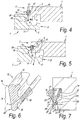
- the horizontally active locking system 6 comprises a male part 8 and a female part 9, which allow to connect two of such floor panels 1 to each other at the aforementioned sides 2-3 by providing one of these floor panels 1 with the pertaining male part 8, by means of a downward movement M, in the female part 9 of the other floor panel, which movement M is illustrated by means of two different positions in the figures 4 and 5 .
- the male part 8 is formed by a downward-directed extremity of a hook-shaped part 10, whereas the female part 9 consists of a seat formed by means of an upward-directed hook-shaped part 11.
- the vertically active locking system 7 comprises a locking element 12, which, in the form of an insert, is provided in one of the sides concerned, in this case, the side 2, more particularly in a recess 13 provided to this aim.
- the locking element 12, or in other words, thus, the insert is illustrated in separate condition in figure 6 .
- this locking element 12 preferably is made as a strip. It is clear that this strip preferably extends over the entire or almost entire length of the side 2.
- this strip consists of synthetic material, however, the use of other materials to this aim is not excluded. Further, it is preferred that the strip has a continuous cross-section over its entire length, which renders it simple to manufacture.
- a synthetic material strip preferably use is made of PVC.
- FIG. 7 The enlarged view of figure 7 shows in greater detail how the strip is attached in the recess 13, which will be discussed further on.
- the locking element 12 is composed at least of a pivotable lock-up body 14 and a press-on portion 15.
- the lock-up body 14 consists of the entire upright part, whereas the press-on portion 15 is formed by the portion inclinedly directed away.
- the locking portion 18 preferably is formed by a portion defining a stop-forming surface 19, which for this purpose is present in the side 3 and preferably is mechanically provided in the core of the floor panel 1.
- the pivotable lock-up body 14, opposite from the extremity 16 forming the locking portion 17, comprises a support portion 20, which is rotatable against a support surface 21 pertaining to the floor panel 1 concerned, and more particularly in a seat 22.
- the support portion 20 in the embodiment of figures 2 to 10 thus the lowermost extremity 23 of the lock-up body 14 is meant.
- the lock-up body 14 as such, between the locking portion 17 and the support portion 20, in other words, between its extremities 16 and 23, is free from hinge portions and bending sections, such in accordance with the second aspect of the invention.
- the lock-up body 14 is made relatively thick and preferably forms a rigid body, which means that the lock-up body 14 can not undergo noticeable deformations between its extremities when pressures are exerted hereupon, which usually may arise with "push-lock" couplings.
- the support portion 20 in the represented embodiment is made as a free extremity, which is positively supported at least in vertical direction by a support portion 24, more particularly support surface 21, pertaining to the floor panel 1.
- the support portion 20 of the lock-up body 14 preferably even is supported in two directions, at least in a coupled condition of two floor panels 1, namely in vertical direction V, in this case, thus, downward, as well as in proximal direction P in respect to the floor panel 1, this latter by means of the lateral wall 25 of the seat 22.
- the floor panel 1 also comprises a stop-forming part 26, which, in a distal direction D in respect to the floor panel 1, forms a blockage for the support portion 20 or, thus, for the extremity 23 of the lock-up body 14.
- a proper seat 22 can be formed, as a result of which the support portion 20 is sitting enclosed at three sides. In this manner, the seat can function as a rather precisely defined hinge point.
- the locking element 12 preferably consists of a strip which is attached in a recess, in the represented example, thus, the recess 13, in the floor panel 1 and that attachment provisions are present therein, retaining the strip in the recess. More particularly, it is preferred that the strip is snap-fitted in the recess and/or is sitting enclosed therein due to the design, which principle also has been applied in the embodiment of figures 1 to 10 . As indicated in figure 7 , the opening A of the recess is smaller than the largest dimension B of the strip, with the consequence that the latter automatically is retained in the recess 13.
- the strip or, thus, the locking element 12 simply can be provided at a floor panel 1 by pressing it into the recess 13, for example, by means of a press-on portion or sliding block 27. Due to the exerted pressure, the strip is deformed and fits through opening A, after which it regains its original shape and becomes enclosed in the recess. More particularly, hereby the press-on portion 15 is bent in the manner as represented, in order to finally bounce into place.
- FIG. 1 also applies the fourth aspect of the invention, namely in that the lock-up body 14 is rotatable around a rotation point, support point, respectively, and the press-on portion 15, at a distance from the rotation point, and more particularly at a distance D1 from the actual support point, engages at the lock-up body 14.
- a “point” also a “zone” can be intended.
- a “support point” also may extend over a "zone”.
- the press-on portion 15 preferably consists at least, viewed in cross-section, of a leg adjoining to the rear side of the lock-up body 14, which leg, in free condition, extends obliquely in respect to the lock-up body 14, such from a location P1 situated between the two extremities of the lock-up body.
- this leg also globally extends under an angle A1 of less than 70 degrees in respect to the portion 28 of the lock-up body 14, which portion extends from said location P1 towards the locking portion 17.
- the press-on portion 15 preferably consists of an elastic material, and more particularly a material, which as such is more flexible than the material of the lock-up body 14.
- this is also synthetic material, and in the most preferred embodiment, the press-on portion 15 is made in one piece with the lock-up body 14 by means of coextrusion.
- the co-extruded materials are represented with different shading.
- a locking element 12 in cross-section can only be of small dimensions, in view of the fact that it must be integrated in the edge of floor panels having in practice a thickness which usually is less than 2 cm and in many cases is even less than 1 cm.
- the space then available for the locking element 12 often only lies in the order of magnitude of 5 millimeters or less.
- different flexibilities must be incorporated into the locking element, the possibilities thus also are limited when one desires to perform this in a traditional manner by working with different thicknesses.
- co-extruded materials may consist of the same or similar basic material and, for example, differ from each other only in that certain components are added to the one material, or certain components are present to a larger extent.
- the entire strip will consist of PVC, however, the more flexible portion will be formed of PVC to which a larger quantity of plasticizer is added.
- this transition T in the embodiment of figures 1 to 10 , preferably is situated at a distance X from the lock-up body. Thereby, a more rigid guiding portion remains present at the basis of the press-on portion 1, which promotes the snap-on effect represented in figure 8 .
- the press-on portion 15 viewed in cross-section, consists of only one leg.
- a tensioning system 29 is integrated in the vertically active locking system, which tensioning system provides for that a good locking is created when the lock-up body 14 is angled out.
- a tensioning system here a system is intended which, when angling out the lock-up body 14, additionally effects the approach among the locking portions 17 and 18.
- the cam surface 30, which consists at least of an effective contact zone 31 and possibly an entry zone 32, preferably extends over a width B1 of at least 60% of the total width B2 of the lock-up body 14, which allows providing a gradual transition, which promotes a good wedge effect.
- the entry zone 32 preferably is somewhat steeper than the contact zone 31 and is intended to provide for that the lock-up body 14 initially always will get smoothly beneath the surface 19.
- the cam surface 30 preferably extends such that, as represented in figures 9 and 10 , according to a direction R, from the most outwardly situated edge 33 to the most inwardly situated edge 34, the cam surface 30 shows an increasing elevation E, such that the effective length of the lock-up body 14 increases for the successive points of the cam surface according to the direction R.
- the effective length is the distance between the locations where the lock-up body comes into contact at the top and at the bottom.
- the cam surface 30 and the surface 19 situated opposite thereof preferably are performed such that a displacement of the lock-up body 14 as a consequence of tolerance differences results in a smaller or no displacement of the contact zone, more particularly the contact point, between both locking portions 17 and 18.
- the amount of the displacement of the contact zone or the contact point is less than 50% of the size of the displacement of the cam surface 30. This is illustrated in the following by means of figure 10 .
- a first condition with a contact point in position C1 is represented in solid line.
- a first pair of floor panels may come into contact, for example, as represented in solid line, whereas another pair, due to tolerance differences, comes into contact as represented in dashed line. Due to a cam shape according to the invention, it is then prevented that in the second case the contact point C2 would be situated too far from the edges of the floor panels.
- the locking portion 17 of the lock-up body 14 preferably is performed in the form of a broadened extremity of the lock-up body 14, due to which more space is offered for realizing a desired cam surface 30.
- the inclinations of the cam surface 30 and the surface 19 cooperating therewith preferably are realized such that they always define a tangent line L1-L2 in their contact zone, contact point C1-C2, respectively, the inclination angles of which with the horizontal, of which solely one is indicated in figure 10 by A2, are less than 35 degrees.
- Figures 11 and 12 show that the contact point C can also be displaced by the selection of the shape of the surface 19 with which the lock-up body 14 cooperates in coupled condition. It is noted that in coupled condition the connection line L3 between the contact point C, or the middle of the contact zone when the contact is wider than a point, and a point where the lock-up body 14 is supported, is as vertical as possible, as then, amongst others, horizontal force components, which might force the lock-up body back, remain limited. In this respect, it is also preferred that the distance D3, at which the contact C, the center op the contact zone, respectively, is situated from the plane where the floor panels 1 fit against each other, is smaller than 1 mm and still better is smaller than 0.8 mm.
- the locking element 12 and the recess 13 are performed such that this locking element 12, in the free, uncoupled condition of the floor panel 1 concerned, is sitting at least partially with its locking portion 17 within the recess 13.
- FIG 13 shows the application of the embodiment represented in figures 1 to 10 in so-called prefabricated parquet, more particularly in so-called "engineered wood".
- this relates to floor panels 1 which are constructed from a core 38 composed of strips 35-36-37, a top layer 39 of wood, as well as a backing layer 40 of wood.
- the top layer 39 consists of wood of a good quality, which functions as a visible decorative layer.
- the backing layer 39 may consist of a cheaper kind of wood.
- the strips 35 preferably also consist of a cheaper, for example, soft kind of wood.
- it is preferred that at the extremities of the floor panels 1 strips 37-38 of a material are applied which is relatively sturdy and suited for providing the desired profile shapes therein, for example, milling them therein.
- these strips 37-38 consist of MDF (Medium Density Fiberboard) or HDF (High Density Fiberboard). It is clear that the invention can also be applied in combination with other forms of "engineered wood", for example, wherein the core consists of a single continuous MDF/HDF board or of a plywood board.
- Figure 14 represents an application in a laminate floor panel, in this case a so-called DPL (Direct Pressure Laminate), which, in a known manner, consists of a core 41, for example, of MDF or HDF, a top layer 42 on the basis of one or more resin-impregnated layers, for example, a printed decor layer 43 and a so-called overlay 44, as well as a backing layer 45, which also consists of one or more resin-impregnated layers, wherein the whole is consolidated under heat and pressure.
- DPL Direct Pressure Laminate
- Figures 15 and 16 represent a particular embodiment, wherein in the side of the floor panel 1 situated opposite to the lock-up body 14, a recess 46 is provided, wherein, as can be seen in figure 16 , in the longitudinal direction of the edges a rod 47 or the like can be introduced between the floor panels 1, in such a manner that the lock-up body 14 is pushed back and the floor panel concerned can be lifted and thus can be uncoupled.
- Figure 17 represents a variant of the invention, which differs from the above-described embodiment in a number of ways.
- the pivotable lock-up body 14, next to the extremity 23 along which it is pivotable comprise a tensioning system 48, which in this example, as illustrated in the enlarged view of figure 18 , substantially consists of a cam 49 realized at said extremity 23, which cam, when the lock-up body 14 is being pivoted outward, also subjects this lock-up body 14 to an axial displacement V3 in the direction of the locking portion 17.
- the cam 49 to this aim must be realized with a suitable elevation, which can be determined by those skilled in art in function of the desired effect.
- the elevation is illustrated by the distances D4 and D5, wherein D5 is larger than D4.
- the axial displacement V3 contributes to that the lock-up body 14, during coupling, initially can pivot outward in a smooth manner, however, as soon as it is partially pivoted out, rather quickly is seeking contact with the other floor panel 1 before it can pivot outward too far.
- the locking element also is provided with an attachment portion 50 especially provided for this purpose, which portion in this case is performed as a clamped part.
- the clamping action herein is obtained by an elastic bending and/or deformation of the attachment portion 50.
- Figure 17 also shows that the female part 9 can be performed with a relatively low hook-shaped part 10 and further may have such a shape that two of such floor panels 1 can be brought into each other at the respective edges also by sliding them towards each other, whether or not assisted by the fact that the hook-shaped part 11 possibly is elastically bendable.
- This manner of joining is illustrated in figure 20 .
- two possibilities can occur. When the floor panels 1 are held in the same plane and are moved towards each other in this manner, such as indicated by arrow S1, the hook-shaped part 11 is forced to bend out elastically downward.
- the represented coupling parts also allow that two of such panels can be coupled and/or uncoupled by an angling movement, such by applying a suitable height of the hook-shaped part 11 and/or a suitable inclination of the contact surfaces 51-52.
- the locking element 12 according to the invention can be taken up into the sides 2-3 to be coupled at various locations.
- figures 21 to 23 represent three embodiments, wherein this element is provided at the female part 9 instead of the male part 8, whereas figure 24 represents an embodiment, wherein the locking element 12 is provided in the edge region and thus not in the actual seat where the male part fits into the female part.
- press-on portion 15 also may have a bent or folded-over shape.
- Figure 23 represents that the locking element can also be attached in the recess 13 by means of glue 53, possibly by means of a portion especially provided for this purpose, such as an attachment lip 54, which, for example, is in connection with the press-on portion 15.
- the locking element 12, or, thus, the strip can be provided with one or more elastic bending zones, which either form a connection between the actual press-on portion 15 and the lock-up body 14, or a connection between several portions of the press-on portion 15, or still between other portions.
- Such bending zones allow obtaining the desired mutual movability among the composing parts.
- the embodiment of figure 23 is an example thereof, wherein two flexible bending zones 15A are provided, between the attachment lip 54 and the press-on part 15 on the one hand and the press-on part 15 and the lock-up body 14 on the other hand.
- such bending zones 15A are formed by coextrusion during the manufacture of the locking element 12.
- a locking element according to the invention provides for a stable support in vertical direction, whereas in horizontal direction, thus, in the pivoting direction, a flexible movability is effected.
- the application of co-extruded parts assists therein.
- coupling parts can also be provided at the second pair of opposite sides, which coupling parts, in coupled condition, preferably also offer a horizontal as well as a vertical locking.
- These coupling parts at the second pair of sides also can be performed as a "push-lock" coupling, whether or not in accordance with the present invention.
- coupling means will be applied allowing a mutual coupling by means of a pivoting movement between two floor panels to be coupled and/or by means of a shifting movement resulting in a snap-on connection.
- Such coupling parts are widely known from the state of the art and are described, for example, in WO 97/47834 .
- coupling parts 57-58 will be applied allowing at least a connection by means of a pivoting movement, as this allows installing the floor panels, as illustrated in figures 25 and 26 , in a simple manner.
- a new floor panel 1C to be installed then can be simply angled at its side 55 into the preceding row of floor panels 1A, and such just next to a preceding floor panel 1 B in the same row.
- the male part of the new floor panel 1C to be installed then automatically engages in the female part of the preceding floor panel 1B, without the necessity of performing another operation.
- the so-called "push-lock" connection then is situated at the short sides.
- Figure 27 represents an example of the seventh aspect of the invention.
- the locking element 12 consists of a synthetic material strip provided in a recess 13, which strip, in the coupled condition of two floor panels 1, comes into contact with both floor panels 1 and thereby forms a seal, wherein between the upper side 59 of the floor panel 1 and the synthetic material strip also a seal 60-61 is present at the panel edges 62-63.
- the synthetic material strip is applied as a seal against the infiltration of water and thereby offers at least a barrier which at least decelerates and preferably completely blocks the possible infiltration of water in between the coupling parts 4-5, whereas the seal 60, 61, respectively, at the panel edges is intended for protecting the panel material 64, which mostly is based on wood, as such against the penetration of water.
- Possible water which might infiltrate in between two floor panels 1 then can not or only with difficulty infiltrate up to beneath the floor panels 1, whereby the risk of rotting and mould formation beneath the floor panels 1 is restricted, whereas this water also can not penetrate into the floor panels 1 themselves and thus a damage at the floor panels 1 themselves, for example, by swelling, is excluded.
- the moisture present above the synthetic material strip can evaporate in due course.
- the seal against moisture penetration is formed at one side 3 by the contact 65 and at the other side 2 by one or more of the contacts 66, 67 or 68.
- the locking element can be provided with one or more sealing material portions 69, for example, of a relatively soft synthetic material or rubber, which are present at the location of the contacts 65-66-67-68 at the locking element 12.
- sealing material portions can be provided at the synthetic material strip in any manner. In a practical embodiment, this will be performed by means of coextrusion.
- the seals 60-61 at the panel edges 62-63 may have any form. As represented, they are formed, for example, by an impregnation layer or a covering layer, such as a lacquer or varnish layer. They extend from at the top layer downward, each time at least up to one of the locations where said contacts are realized. According to a not represented variant, such seal also may consist in that the top layer extends up to a location where one of the contacts is realized, for example, by applying a top layer which extends over the upper edges downward.
- the top layer also is waterproof. Moreover, it then may consist of any material, such as a laminate, a film, a lacquer layer, a water-repellent or waterproof print, a varnish or the like.
- floor panels which are installed in rows, and then in particular oblong floor panels show the feature that the floor panels will align in the longitudinal direction of the rows and mostly will adjoin well with their sides against each other, whereas at the sides directed perpendicularly to the rows then openings will occur more easily, due to the fact that such floor panels, as a result of production tolerances, often do not have perfectly perpendicularly aligned sides.
- a fast infiltration is possible, and a sealing by means of somewhat elastic coatings on the upper edges of the floor panels mostly is not effective, as the openings are too large to be bridged thereby.
- a sealing principle according to the seventh aspect of the invention will show its benefits.
- transition T is situated closer to the lock-up body 15 than in the embodiment of figure 6 . With suitable dimensions in free condition, it may then be obtained that in the mounted condition a force is generated holding the locking element 12 in permanent contact with the support surface 21.
- Figure 28 represents a variant, which makes clear that the inventive idea of the use of a co-extruded locking element 12 in a so-called "push-lock" system is not restricted to embodiments with a pivotable lock-up body.
- the lock-up body 14 is displaceable and consists of a relatively hard synthetic material
- the press-on portion 15 consists of flexible and elastic synthetic material.
- the co-extruded press-on portion 15 functions as an elastic mass situated behind the lock-up body 14 in a spring-like fashion.
- Figure 29 represents another variant, which is comparable to that of figure 17 .
- the difference consists in that the hook-shaped part 11 of figure 29 is realized considerably higher than in the embodiment of figure 17 , such that the contact surfaces 51-52 at least partially are situated higher than the support surface 21 of the lock-up body.
- Figure 30 represents a preferred variant of an embodiment according to the invention, wherein the locking element 12 is provided in the proximal side of the female part.
- this offers an important advantage.
- the edge 73 is made relatively sharp and straight in order to obtain that the lock-up body 14 in free condition still is seated beneath the edge 73.
- the locking element 12 when the right-hand floor panel is moved downward, comes into contact with the sharp upper edge 74 of the left-hand floor panel, whereby also a scraping effect may be created, which can impede the installation.
- the embodiment of figure 30 does not show this disadvantage, in view of the fact that the rounded underside of the male part then will slide smoothly along the locking element.
- Figure 30 also relates to an embodiment meeting the eighth aspect of the invention mentioned in the introduction, more specifically in that the edges of the floor panels 1 can be joined into each other by a shifting movement S1.
- figure 30 shows the following characteristics:
- the lock-up body 14, and still better the entire locking element 12 realized as an insert is made relatively local, by which in particular is meant that it is only present between a first and a second horizontal level, the first horizontal level N1 of which is situated at a distance beneath the upper side of the coupled floor panels, whereas the second horizontal level N2 is situated lower than the first, however, higher than the lowermost point of the male part.
- figure 3 also shows that said lock-up body 14 extends over a height H which is at least 40% and still better at least 50% of the height difference between the upper side of such coupled floor panels and the lowermost point of the male part, i.e., D7. It is clear that these characteristics are not limited to the embodiment of figure 30 .
- the horizontal distance D6 as measured from the upper edges of the floor panels up to the cooperating point of the contact surfaces 51-52, which is situated farthest away from these upper edges, is at least 1.3 times the distance D7 between the upper side of the floor panels and the underside of the male part, which allows a smooth angling movement.
- the highest point 75 preferably is situated at a level N3, which is lower than the lowermost point of the lock-up body 14.
- Figure 30 represents a particular construction of a press-on portion 15, wherein it is clear that this construction also can be applied in other embodiments of floor panels according to the invention.
- This press-on portion more particularly the construction thereof, shows the following characteristics:
- the floor panels according to the invention in general can be realized such that in coupled condition a so-called "pre-tension" is created, which means that the floor panels at their coupled sides are pressed towards each other by means of a tension force.
- the tension force can be supplied in any manner. For example, it may be generated by the elastic bending of the lip bordering the underside of the female part.
- the principle can be applied which is known from WO 97/47834 , more particularly from figure 23 of said WO 97/47834 .
- floor panels of the present invention can also be equipped with an anti-creak system, more particularly by application of the principle described in WO 2006/032398 .
- Figure 32 shows another embodiment meeting the various aspects and in particular the ninth aspect of the invention.
- the lock-up body 14 and the attachment portion 50 consist of a relatively rigid material and are connected to each other by coextrusion by means of a material part 79 made as a hinge part, which material part consists of a more flexible and elastic material.
- the lock-up body 14 globally forms an angle with the attachment portion 50 and reaches with the extremity functioning as a support portion 20 up to beyond the actual attachment portion 50, in such a manner that at the location 80, where the lock-up body 14 passes along the attachment portion 50, the distance between the lock-up body 14 and the attachment portion 50 is smaller than the distance from the - in this case upwardly protruding - extremity of the lock-up body 14 to the attachment portion 50.
- the material part 79 is situated between the actual attachment portion 50 and said protruding beyond it extremity of the lock-up body 14.
- This design has the advantage that the lock-up body 14, due to the small material quantity at the location 80, can hardly be displaced in respect to the attachment portion 50, with the exception of an angling movement, whereas in upward direction sufficient flexible material of the material part 79 is present in order to hold the lock-up body 14 in a certain position and to allow the desired elastic movement thereof. Still another advantage is that, when the lock-up body 14 is angled in, the material on the location 80 is compressed and the lock-up body 14 also is pushed upward, as a consequence of which it remains in contact with the support surface 21.
- the locking element 12 preferably is supported at least on three locations, on the one hand, at the bottom at the height of the support collar 78, at the top by the upper side 81 of the material part 79, as well as at the height of the represented ribs 82.
- Figure 32 also shows that the attachment portion 60 is provided substantially flat in the recess 13, in other words, that the direction 83 in which this attachment direction 50 extends, deviates little or not at all from the plane of the floor panels.
- this direction 83 which a manufacturer of floor panels can do in a simple manner by positioning the recess 13 somewhat differently, different functioning characteristics in respect to angling the lock-up body in and out can be obtained, such that an optimization is possible.
- FIGS 33 to 37 represent another variant of the invention. A number of differences in respect to the embodiment of figure 32 will be discussed in the following.
- a first difference consists in that the locking element 12 in vertical direction is supported in the recess 13 by means of only three support portions, or at least substantially by only three support portions, one support portion of which is formed by the aforementioned support portion 20 of the lock-up body 14.
- the other two support portions, 84 and 85, respectively, preferably are situated at the upper side and underside of the actual attachment portion 50. More particularly, it is preferred that the support portion 84 situated at the top is located in respect to the floor panel more proximally than the support portion 85 situated at the bottom.
- the support portion 84 of the upper side is located at the - situated proximally in respect to the floor panel 1 - extremity of the actual attachment portion 50, whereas the support portion 85 is located at the distally situated extremity.
- the material part 79 does not form a support point. It is clear that one and the same support portion as such may comprise several contact points, for example, if it should have a ribbed surface.
- the locking element 12 is configured such that in the mounted, however, not impressed condition, namely the one from figure 33 , a certain clamping thereof in the recess 13 is created. This is obtained, for example, by the elastic deformation of the actual body of the attachment portion 50 from the position represented in dashed line in figure 33 to the position represented in solid line, which deformation is achieved during clamping of the locking element 12 in the recess 13.
- a second difference consists in that the actual attachment portion 50 is configured and attached in the recess 13 such, that during joining of two floor panels 1 a certain movability of the actual attachment portion 50 is possible.
- the support portion 85 to this aim is provided with a guiding surface 86, which can cooperate with an inclined guiding surface 87 at the floor panel, whereby a small displacement 88 of the attachment portion 50 is possible, such as will be described in the following by means of figures 34 to 37 .
- Figures 34 to 37 represent successive conditions of the locking element 12 during joining of two floor panels 1.
- Figure 34 shows the rest position. Due to the tension force in this entity, the support portion 85 has the tendency to slide downward along the guiding surface 8 until it reaches the represented position.
- Figures 35 and 36 represent successive conditions, wherein the right-hand panel is angled down and the lock-up body 14 is pushed aside. Due to the fact that on the location 80 very little material of the material portion 79 is present between the lock-up body 14 and the actual attachment portion 50, this latter, starting from a certain moment, is also forced somewhat inward, wherein it moves with its guiding surface 86 along the guiding surface 87, until it reaches a condition, as depicted in figure 36 .
- the attachment portion 50 so to speak, makes room for the movement of the lock-up body 14 and thereby performs a more or less rotating displacement 88, such, for example, until it comes with its extremity 89 into contact with the deepest point of the recess 13.
- the support portion 20 rotates practically exclusively at its place along its highest point and performs little or no rolling movement along the floor panel.
- the whole may be designed such that the actual attachment portion 50, after the locking of the floor panels, also more or less arrives back at its initial location, as depicted in figure 37 .
- the downward-protruding support portion 85 thus indeed provides for a blocking function, which determines the normal position of the locking element 12 in the recess, however, with a certain load in fact will allow an extra movement 88.
- the locking element 12 may also be configured such that in the most impressed condition, a free space 90 is created between the support portion 20 and the wall of the recess 13.
- the proper configuration for this purpose can be determined by tests.
- a deformation may be provided in the wall of the recess 13, which deformation cooperates with a deformation in the attachment portion 50, as a result of which the locking element 12, so to speak, can be fixedly attached in the recess 13 by means of a snap-on connection.
- the locking element 12 viewed in cross-section, consists at least of an actual attachment portion 50, a lock-up body 14, which can perform at least an angling movement, and a material part 79, which is present between the attachment portion 50 and the lock-up body 14, which material part consists of a material which is more flexible and elastic than the material of the lock-up body 14 and which thereby functions at least as a hinge part. From the above, it is clear that all other characteristics described by means of figures 33 to 37 are facultative and that all these facultative characteristics can be mutually combined at random.
- the attachment portion 50, the material part 79 and the lock-up body 40 by means of coextrusion are realized as a one-piece strip.
- the actual attachment portion 50 and the lock-up body 14 are manufactured of one and the same material, whereas the material part 79 consists of a more flexible material.
- the same basic substances can be applied for both materials, however, they may differ from each other by the addition of additives, such as plasticizers.
- the material of the material part 79 preferably behaves like a relatively soft rubber, whereas the material of the actual attachment portion 50 and of the lock-up body 40 preferably behaves like a classic synthetic material, such as common PVC, and thus, in view of the small dimensions in cross-sections, also behaves in a relatively rigid manner.
- the support portion for example, 20, is rotatable against a support surface, for example, 21
- a support surface for example, 21
- the contact will normally be present indeed from a certain angling-out of the lock-up body.
- a local rotation, or "pivoting against a support or rotation point”, may concern a turning around a point or zone which is, are, respectively, situated in the support surface 21, as well as a rotation point or rotation zone at a distance from the support surface.
- the recess 13 can be realized in any manner. According to a preferred characteristic, this takes place by means of a milling treatment, which is performed when realizing said female coupling part.
- strip-shaped locking element 12 in the recess 13 may also be performed in any manner.
- two non-restrictive embodiments of methods for this purpose are described, which can be applied within the scope of the present invention.
- the strip-shaped locking element 12 systematically is fixedly pressed on in the recess 13, preferably is rolled into it.
- this takes place, as represented in figure 38 , by displacing the floor panels 1, which mostly are lying upside down, by means of a conveyor 92, supplying thereto a strip 93 from which the strip-shaped locking elements 12 have to be cut off, and fixedly pressing on this strip 93, the locking elements 12 cut off therefrom, respectively, in the recesses 13 of the successive floor panels 1 by means of a locally installed rotating press-on roll 94.
- Figures 39 to 41 show, how the strip is pressed on in the recess 13 by means of the press-on roll 94, which to this aim can be provided with a profiled surface 95.
- the strip 93 can be supplied from a stock, for example, a wound stock. Further, a cutting device 96 is present for separating the locking elements 12 at a suitable length from the strip 93, which device is illustrated schematically only. It is clear that in practice the necessary guiding elements will be present in order to have the strip 93 and the locking element 12 follow the correct course, of which the guiding element 97 in figures 40 and 41 is an example.
- Figure 42 shows a variant, wherein according to the invention a method is applied wherein a cut to length strip-shaped locking element 12 over its entire length simultaneously is pressed into the recess 13.
- this preferably is performed by means of a device with a slider or plunger 98, with which the locking element 12 laterally is pushed over its entire length at one go into the recess 13.
- the device preferably comprises a holder 99, in which a space 100 is defined, in which a locking element 12 to be applied can be taken up and wherein the plunger 98 can be shifted.
- the holder 99 together with the plunger 98 present therein and the locking element 12 present therein, is positioned opposite to the edge of a floor panel concerned, as illustrated in figure 42 , after which, by displacing the plunger 98 to and fro to the right, the locking element 12 is brought from the position represented in solid line to this position represented in dashed line, after which it remains in the recess 13.
- Figure 43 schematically shows how the device from figure 42 can be applied in practice.
- the floor panels 1 are displaced along a conveyor 92.
- the holder 99 too, can perform various displacements, as will become clear from the function sequence described in the following.
- the holder 99 is situated in a position 101.
- a strip 93 is supplied to the holder, which strip is provided in the space 100.
- this may be realized, for example, by displacing the holder 99 along a press-on roll 103 with which the strip 93, which is supplied from a not represented stock, is directed into the space 100 of the holder 99, as illustrated for the position 102 of the holder 99.
- the length necessary for forming the locking element 12 is then cut off by means of the schematically represented cutting device 104.
- a floor panel has arrived in a position 105.
- the holder 99 can follow the movement of a passing floor panel 1, as a result of which they come into positions 106 and 107, respectively.
- the holder 99 and the floor panel concerned can be presented to each other, for example, by laterally displacing the holder 99 until it reaches position 108.
- the condition of figure 42 is obtained, after which it suffices to activate the plunger 98 in order to bring the locking element 12 into the recess 13.
- all this can take place during the continuous conveyance of the floor panels, for example, after they exit the milling device and before they are packaged.
- the holder 99, or possibly several applied holders 99 then can be displaced to and fro through all abovementioned positions.
- multiple holders on a conveyor belt might be used, wherein a holder then is brought from position 108 back to position 101, while already one or more other holders pass through the same trajectory.
- panels also may be supplied stepwise instead of continuously to an insertion device for locking elements 12.
- a lock-up body 14 which can be pivoted or bent out, it is intended that it can be pivoted or can be bent out in the plane of a cross-section.
- the support portion of the lock-up body, around which it is rotatable is a support portion which is intended to take up the forces when the floor panels attempt to get away from each other in upward direction.
- a rotatable locking element is known, which, however, contrary to the invention, does not rotate around a support point which, as above, is intended to provide for a lock-up support function which counteracts the unlocking of the floor panels.
- a “rigid” lock-up body it is meant that this rigidity exists at least in a plane according to the cross-section.
- the invention and in particular the locking element according to the invention, can be employed in various floor panels, amongst others, in laminate floor panels, prefabricated floor panels, such as so-called "engineered wood", solid parquet, veneer parquet, as well as floor panels which are provided with any top layer, for example, vinyl, linoleum, stone, metal and the like.
- the core of such floor panel not necessary has to consist of wood or a product on the basis of wood and in principle may consist of any material, thus, for example, also synthetic material.
- the invention relates to floor panels as defined in the appended claims.
- the invention also relates to one or more of the items as listed below:
Applications Claiming Priority (6)
| Application Number | Priority Date | Filing Date | Title |
|---|---|---|---|
| BE2007/0567A BE1018600A5 (nl) | 2007-11-23 | 2007-11-23 | Vloerpaneel. |
| US7120108P | 2008-04-17 | 2008-04-17 | |
| DE202008008597U DE202008008597U1 (de) | 2007-11-23 | 2008-06-26 | Fußbodenpaneel |
| PCT/IB2008/003133 WO2009066153A2 (en) | 2007-11-23 | 2008-11-19 | Floor panel |
| EP16161616.4A EP3103938B1 (de) | 2007-11-23 | 2008-11-19 | Bodenpaneel |
| EP08851947.5A EP2217775B1 (de) | 2007-11-23 | 2008-11-19 | Bodenplatte |
Related Parent Applications (3)
| Application Number | Title | Priority Date | Filing Date |
|---|---|---|---|
| EP16161616.4A Division EP3103938B1 (de) | 2007-11-23 | 2008-11-19 | Bodenpaneel |
| EP16161616.4A Division-Into EP3103938B1 (de) | 2007-11-23 | 2008-11-19 | Bodenpaneel |
| EP08851947.5A Division EP2217775B1 (de) | 2007-11-23 | 2008-11-19 | Bodenplatte |
Publications (3)
| Publication Number | Publication Date |
|---|---|
| EP3859098A1 true EP3859098A1 (de) | 2021-08-04 |
| EP3859098B1 EP3859098B1 (de) | 2024-02-28 |
| EP3859098B8 EP3859098B8 (de) | 2024-04-03 |
Family
ID=39535710
Family Applications (4)
| Application Number | Title | Priority Date | Filing Date |
|---|---|---|---|
| EP16161616.4A Active EP3103938B1 (de) | 2007-11-23 | 2008-11-19 | Bodenpaneel |
| EP14187475.0A Active EP2843154B1 (de) | 2007-11-23 | 2008-11-19 | Bodenplatte |
| EP08851947.5A Active EP2217775B1 (de) | 2007-11-23 | 2008-11-19 | Bodenplatte |
| EP21161315.3A Active EP3859098B8 (de) | 2007-11-23 | 2008-11-19 | Bodenpaneel |
Family Applications Before (3)
| Application Number | Title | Priority Date | Filing Date |
|---|---|---|---|
| EP16161616.4A Active EP3103938B1 (de) | 2007-11-23 | 2008-11-19 | Bodenpaneel |
| EP14187475.0A Active EP2843154B1 (de) | 2007-11-23 | 2008-11-19 | Bodenplatte |
| EP08851947.5A Active EP2217775B1 (de) | 2007-11-23 | 2008-11-19 | Bodenplatte |
Country Status (23)
| Country | Link |
|---|---|
| US (8) | US8621814B2 (de) |
| EP (4) | EP3103938B1 (de) |
| JP (1) | JP5385911B2 (de) |
| KR (1) | KR101651691B1 (de) |
| CN (3) | CN103452275B (de) |
| AU (1) | AU2008327616B2 (de) |
| BE (1) | BE1018600A5 (de) |
| BR (1) | BRPI0819640B1 (de) |
| CA (2) | CA2994639C (de) |
| DE (1) | DE202008008597U1 (de) |
| DK (2) | DK2217775T3 (de) |
| EA (2) | EA025886B1 (de) |
| ES (2) | ES2626781T3 (de) |
| HR (2) | HRP20160707T1 (de) |
| HU (2) | HUE029352T2 (de) |
| LT (1) | LT2843154T (de) |
| MX (2) | MX2010004973A (de) |
| MY (1) | MY154207A (de) |
| PL (2) | PL2217775T3 (de) |
| PT (2) | PT2217775T (de) |
| UA (1) | UA101813C2 (de) |
| WO (1) | WO2009066153A2 (de) |
| ZA (1) | ZA201001948B (de) |
Families Citing this family (118)
| Publication number | Priority date | Publication date | Assignee | Title |
|---|---|---|---|---|
| US7131242B2 (en) | 1995-03-07 | 2006-11-07 | Pergo (Europe) Ab | Flooring panel or wall panel and use thereof |
| SE9500810D0 (sv) | 1995-03-07 | 1995-03-07 | Perstorp Flooring Ab | Golvplatta |
| US7992358B2 (en) | 1998-02-04 | 2011-08-09 | Pergo AG | Guiding means at a joint |
| SE514645C2 (sv) | 1998-10-06 | 2001-03-26 | Perstorp Flooring Ab | Golvbeläggningsmaterial innefattande skivformiga golvelement avsedda att sammanfogas av separata sammanfogningsprofiler |
| SE518184C2 (sv) | 2000-03-31 | 2002-09-03 | Perstorp Flooring Ab | Golvbeläggningsmaterial innefattande skivformiga golvelement vilka sammanfogas med hjälp av sammankopplingsorgan |
| US7841144B2 (en) | 2005-03-30 | 2010-11-30 | Valinge Innovation Ab | Mechanical locking system for panels and method of installing same |
| BE1017157A3 (nl) * | 2006-06-02 | 2008-03-04 | Flooring Ind Ltd | Vloerbekleding, vloerelement en werkwijze voor het vervaardigen van vloerelementen. |
| SE531111C2 (sv) | 2006-12-08 | 2008-12-23 | Vaelinge Innovation Ab | Mekanisk låsning av golvpaneler |
| US7726088B2 (en) * | 2007-07-20 | 2010-06-01 | Moritz Andre Muehlebach | Flooring system |
| BE1018600A5 (nl) | 2007-11-23 | 2011-04-05 | Flooring Ind Ltd Sarl | Vloerpaneel. |
| US8627862B2 (en) | 2008-01-31 | 2014-01-14 | Valinge Innovation Ab | Mechanical locking of floor panels, methods to install and uninstall panels, a method and an equipment to produce the locking system, a method to connect a displaceable tongue to a panel and a tongue blank |
| EP2163709B1 (de) | 2008-09-12 | 2012-10-10 | Flooring Industries Limited, SARL | Verfahren zum Verlegen eines Fussbodenbelags und Mittel zur Behandlung eines Untergrundes für dieses Verfahren |
| DE102008047099B4 (de) * | 2008-09-12 | 2010-05-12 | Guido Schulte | Fußbodenbelag |
| DE102008047098B3 (de) * | 2008-09-12 | 2010-04-08 | Guido Schulte | Fußbodenbelag |
| SE0802284L (sv) * | 2008-10-27 | 2010-03-16 | Micael Johansson | Förfarande för lagning och en anordning för genomförande därav |
| WO2010075839A1 (de) * | 2008-12-16 | 2010-07-08 | Hamberger Industriewerke Gmbh | Fussbodenbelag |
| BE1018389A3 (nl) * | 2008-12-17 | 2010-10-05 | Unilin Bvba | Samengesteld element, meerlagige plaat en paneelvormig element voor het vormen van zulk samengesteld element. |
| BE1018680A5 (nl) | 2008-12-19 | 2011-06-07 | Flooring Ind Ltd Sarl | Werkwijzen voor het vervaardigen van panelen en paneel hierbij bekomen. |
| KR101616593B1 (ko) | 2008-12-19 | 2016-05-12 | 플로어링 인더스트리즈 리미티드 에스에이알엘 | 코팅 패널 및 이러한 패널의 제조 방법 |
| EP2202056A1 (de) | 2008-12-23 | 2010-06-30 | Unilin Industries, BVBA | Bodenplatte und Verfahren zur Herstellung von Bodenplatten |
| BE1018627A5 (nl) * | 2009-01-16 | 2011-05-03 | Flooring Ind Ltd Sarl | Vloerpaneel. |
| BE1018728A3 (nl) * | 2009-04-22 | 2011-07-05 | Flooring Ind Ltd Sarl | Vloerpaneel. |
| CN102439245A (zh) | 2009-04-27 | 2012-05-02 | 莫赫地板公司 | 地板系统及制造和使用该地板系统的方法 |
| DE102009022483A1 (de) * | 2009-05-25 | 2010-12-02 | Pergo (Europe) Ab | Set von Paneelen, insbesondere von Fußbodenpaneelen |
| DE102009034902B4 (de) * | 2009-07-27 | 2015-10-01 | Guido Schulte | Belag aus mechanisch miteinander verbindbaren Paneelen |
| DE102009041297B4 (de) * | 2009-09-15 | 2018-10-11 | Guido Schulte | Belag aus mechanisch miteinander verbindbaren Elementen und ein Verfahren zur Herstellung von Elementen |
| DE102009048050B3 (de) * | 2009-10-02 | 2011-01-20 | Guido Schulte | Belag aus mechanischen miteinander verbindbaren Elementen |
| PL2333195T3 (pl) | 2009-12-14 | 2014-12-31 | Barlinek Sa | Podłoga wykonana z paneli podłogowych z osobnymi środkami łączącymi |
| ES2734439T3 (es) | 2009-12-22 | 2019-12-05 | Flooring Ind Ltd Sarl | Método para producir paneles de revestimiento |
| US8544230B2 (en) | 2010-01-12 | 2013-10-01 | Valinge Innovation Ab | Mechanical locking system for floor panels |
| EP2524091B1 (de) * | 2010-01-14 | 2019-04-03 | Unilin, BVBA | Bodenplattenanordnung |
| DE102010004717A1 (de) * | 2010-01-15 | 2011-07-21 | Pergo (Europe) Ab | Set aus Paneelen umfassend Halteprofile mit einem separaten Clip sowie Verfahren zum Einbringen des Clips |
| US8402707B2 (en) * | 2010-01-29 | 2013-03-26 | Royal Group Inc. | Interlocking panel system |
| CA2786680C (en) | 2010-02-04 | 2018-06-12 | Vaelinge Innovation Ab | Mechanical locking system for floor panels and a tongue therefore |
| DE102010012572B3 (de) * | 2010-03-23 | 2011-07-14 | Fritz Egger Gmbh & Co. Og | System von wenigstens zwei Paneelen |
| US9003735B2 (en) | 2010-04-15 | 2015-04-14 | Spanolux N.V.—Div. Balterio | Floor panel assembly |
| CA2906474C (en) * | 2010-05-10 | 2018-12-18 | Pergo (Europe) Ab | Set of panels |
| BE1019501A5 (nl) | 2010-05-10 | 2012-08-07 | Flooring Ind Ltd Sarl | Vloerpaneel en werkwijze voor het vervaardigen van vloerpanelen. |
| US8925275B2 (en) | 2010-05-10 | 2015-01-06 | Flooring Industries Limited, Sarl | Floor panel |
| BE1019331A5 (nl) | 2010-05-10 | 2012-06-05 | Flooring Ind Ltd Sarl | Vloerpaneel en werkwijzen voor het vervaardigen van vloerpanelen. |
| BE1019747A3 (nl) | 2010-07-15 | 2012-12-04 | Flooring Ind Ltd Sarl | Bekleding, alsmede panelen en hulpstukken daarbij aangewend. |
| US9719542B2 (en) | 2010-06-03 | 2017-08-01 | Unilin, Bvba | Composed element and corner connection applied herewith |
| BE1019383A3 (nl) | 2010-06-23 | 2012-06-05 | Flooring Ind Ltd Sarl | Werkwijze voor het vervaardigen van panelen en paneel hierbij bekomen. |
| US8806832B2 (en) | 2011-03-18 | 2014-08-19 | Inotec Global Limited | Vertical joint system and associated surface covering system |
| BE1019891A5 (nl) | 2011-03-28 | 2013-02-05 | Unilin Bvba | Samengesteld element en rugwandconstructie hierbij toegepast. |
| EP2526819A1 (de) * | 2011-05-25 | 2012-11-28 | Steen Sauer | Zusammenbau einer Schublade |
| DE102011104718B4 (de) * | 2011-06-06 | 2016-08-04 | Fritz Egger Gmbh & Co. Og | Fußbodenpaneel mit einer einen Sperrriegel afweisenden Seitenkante |
| BE1020044A5 (nl) | 2011-06-29 | 2013-04-02 | Unilin Bvba | Lade, ladeconstructie en werkwijze voor het vervaardigen van een lade. |
| UA114715C2 (uk) | 2011-07-05 | 2017-07-25 | Сералок Інновейшн Аб | Механічна фіксація панелей настилу підлоги до язичка з нанесеним шаром клею |
| US9725912B2 (en) | 2011-07-11 | 2017-08-08 | Ceraloc Innovation Ab | Mechanical locking system for floor panels |
| US8650826B2 (en) | 2011-07-19 | 2014-02-18 | Valinge Flooring Technology Ab | Mechanical locking system for floor panels |
| US8857126B2 (en) | 2011-08-15 | 2014-10-14 | Valinge Flooring Technology Ab | Mechanical locking system for floor panels |
| US8769905B2 (en) * | 2011-08-15 | 2014-07-08 | Valinge Flooring Technology Ab | Mechanical locking system for floor panels |
| MY175339A (en) * | 2011-08-29 | 2020-06-19 | Valinge Flooring Tech Ab | Mechanical locking system for floor panels |
| BE1020305A5 (nl) | 2011-12-05 | 2013-07-02 | Unilin Bvba | Verpakte set panelen. |
| DE102011056494A1 (de) * | 2011-12-15 | 2013-06-20 | Pergo (Europe) Ab | Set aus Paneelen mit Clip |
| DE102012013742A1 (de) * | 2011-12-19 | 2013-06-20 | Fritz Egger Gmbh & Co. Og | Paneel eines Fußbodenbelags mit Fremdelement |
| BE1020433A3 (nl) * | 2012-01-05 | 2013-10-01 | Flooring Ind Ltd Sarl | Paneel. |
| WO2013102804A2 (en) | 2012-01-05 | 2013-07-11 | Flooring Industries Limited, Sarl | Panel |
| EP2812510B1 (de) | 2012-02-07 | 2018-03-07 | Flooring Industries Limited, SARL | Fussbodenpaneel zur bekleidung eines fussbodens, fussbodenbekleidung ausgebilded aus solchen fussbodenpaneelen und produktionsverfahren von solchen fussbodenpaneelen |
| US10760283B2 (en) * | 2012-02-23 | 2020-09-01 | Admiral Composite Technologies, Inc. | Deck system and components |
| US9394698B2 (en) | 2012-02-23 | 2016-07-19 | Admiral Composite Technologies, Inc. | Deck system and components |
| CA2867578C (en) * | 2012-04-04 | 2020-04-28 | Valinge Innovation Ab | Method for producing a mechanical locking system for building panels |
| EP2852722B1 (de) * | 2012-04-04 | 2017-06-07 | Välinge Innovation AB | Bauplatte mit einem mechanischen arretierungssystem |
| US9140010B2 (en) | 2012-07-02 | 2015-09-22 | Valinge Flooring Technology Ab | Panel forming |
| US10035358B2 (en) | 2012-07-17 | 2018-07-31 | Ceraloc Innovation Ab | Panels with digital embossed in register surface |
| US9446602B2 (en) * | 2012-07-26 | 2016-09-20 | Ceraloc Innovation Ab | Digital binder printing |
| EP2895667B1 (de) | 2012-08-27 | 2019-12-04 | Pergo (Europe) AB | Tafel |
| EP2923012B1 (de) * | 2012-11-22 | 2019-10-16 | Ceraloc Innovation AB | Mechanisches verriegelungssystem für bodenpaneele |
| US20140199495A1 (en) | 2013-01-11 | 2014-07-17 | Floor Iptech Ab | Digital printing and embossing |
| KR102184061B1 (ko) * | 2013-01-11 | 2020-11-30 | 플로어링 인더스트리즈 리미티드 에스에이알엘 | 플로어 커버링을 형성하기 위한 플로어 패널, 이러한 플로어 패널들로 형성된 플로어 커버링 및 이러한 플로어 패널들을 제조하기 위한 방법 |
| GB2538492A (en) | 2015-05-11 | 2016-11-23 | Cook Medical Technologies Llc | Aneurysm treatment assembly |
| US10041212B2 (en) | 2013-02-04 | 2018-08-07 | Ceraloc Innovation Ab | Digital overlay |
| BE1021833B1 (nl) * | 2013-05-30 | 2016-01-21 | Flooring Industries Limited Sarl | Paneel |
| EP4166731A1 (de) * | 2013-06-27 | 2023-04-19 | Välinge Innovation AB | Bauplatte mit einem mechanischen verriegelungssystem |
| WO2015070890A1 (en) * | 2013-11-12 | 2015-05-21 | Grigorij Wagner | Flooring component |
| WO2015104680A1 (en) | 2014-01-09 | 2015-07-16 | Flooring Industries Limited, Sarl | Floor panel for forming a floor covering |
| CN105178549A (zh) * | 2014-05-13 | 2015-12-23 | 文森特·弗兰克·卡鲁巴 | 甲板系统和部件 |
| WO2015174914A1 (en) | 2014-05-14 | 2015-11-19 | Välinge Innovation AB | Building panel with a mechanical locking system |
| US10246883B2 (en) | 2014-05-14 | 2019-04-02 | Valinge Innovation Ab | Building panel with a mechanical locking system |
| MY183052A (en) | 2014-11-27 | 2021-02-09 | Valinge Innovation Ab | Mechanical locking system for floor panels |
| CA2971464A1 (en) * | 2014-12-19 | 2016-06-23 | Kinan KHATIB | Connection assembly between two components |
| US9650792B2 (en) * | 2014-12-23 | 2017-05-16 | Afi Licensing Llc | Interlocking floor panels and floor system |
| WO2016113706A1 (en) | 2015-01-15 | 2016-07-21 | Flooring Industries Limited, Sarl | Floor panel for forming a floor covering |
| DE202015101572U1 (de) | 2015-03-27 | 2015-04-21 | Guido Schulte | Belag von im Verbund verlegten rechteckigen oder quadratischen Paneelen |
| EP3916171A1 (de) | 2015-05-12 | 2021-12-01 | Aladdin Manufacturing Corporation | Bodenplatte |
| DE102015208904A1 (de) * | 2015-05-13 | 2016-11-17 | Falquon Gmbh | Paneel und Verfahren zum Verlegen von Paneelen |
| BE1023446B1 (nl) | 2015-09-14 | 2017-03-22 | Ivc N.V. | Werkwijze voor het vervaardigen van vloerpanelen en vloerpaneel voor het vormen van een vloerbekleding |
| RU2730138C2 (ru) * | 2015-10-08 | 2020-08-19 | Берриаллок Нв | Набор панелей для покрытия полов, стен или потолков |
| BE1023545B1 (nl) | 2015-10-23 | 2017-04-28 | Flooring Industries Limited, Sarl | Set van vloerpanelen voor het vormen van een vloerbekleding |
| CN106639032B (zh) * | 2015-10-29 | 2020-05-29 | 北新集团建材股份有限公司 | 一种旋入式骨架、连接骨架和墙体拼接结构及其拼接方法 |
| DE102015121761A1 (de) * | 2015-12-14 | 2017-06-14 | Guido Schulte | Mechanische Verbindung für Paneele |
| BE1023817B1 (nl) | 2016-01-15 | 2017-08-01 | Unilin Bvba | Vloerpaneel voor het vormen van een vloerbekleding, en substraat voor een paneel |
| BE1024157B1 (nl) | 2016-04-25 | 2017-11-24 | Flooring Industries Limited, Sarl | Set van vloerpanelen en werkwijze voor het installeren van deze set van vloerpanelen. |
| DE102016107650B4 (de) * | 2016-04-25 | 2022-01-20 | Guido Schulte | Verfahren und Vorrichtung zur Montage eines Verriegelungselementes an einem Paneel |
| WO2017187298A2 (en) | 2016-04-25 | 2017-11-02 | Flooring Industries Limited, Sarl | Set of floor panels and method for installing this set of floor panels |
| CN106049803A (zh) * | 2016-05-31 | 2016-10-26 | 安徽森泰木塑集团股份有限公司 | 一种无缝拼接地板及其拼接密封条 |
| BE1024723B1 (nl) | 2016-11-10 | 2018-06-11 | Ivc Bvba | Vloerpaneel en werkwijze voor het vervaardigen van een vloerpaneel. |
| SE541420C2 (en) * | 2016-12-16 | 2019-09-24 | Vaelinge Innovation Ab | A set of decking boards provided with a connecting system |
| BE1025875B1 (nl) | 2018-01-04 | 2019-08-06 | Unilin Bvba | Werkwijzen voor het vervaardigen van panelen |
| EP3737805B1 (de) * | 2018-01-11 | 2024-04-03 | Unilin, BV | Satz aus bodenplatten und verfahren zum einbau des satzes aus bodenplatten |
| WO2019142161A1 (en) * | 2018-01-22 | 2019-07-25 | Inovame | Panel whose coupling means are suitable for connecting the longitudinal sides and/or end sides to each other |
| EP3908718A4 (de) | 2019-01-10 | 2022-10-12 | Välinge Innovation AB | Satz von vertikal entriegelbaren paneelen, verfahren und vorrichtung dafür |
| BE1027032B1 (nl) * | 2019-02-07 | 2020-09-07 | Flooring Ind Ltd Sarl | Paneel en bekleding gevormd met dergelijke panelen |
| EP3934866A4 (de) | 2019-03-05 | 2022-12-28 | Ceraloc Innovation AB | Verfahren zur formung von nuten in einem plattenelement und zugehöriges paneel |
| EP3947849A4 (de) | 2019-03-25 | 2022-12-07 | Ceraloc Innovation AB | Mineralisches paneel mit nuten und verfahren zur herstellung von nuten |
| DE102019134858A1 (de) * | 2019-12-18 | 2021-06-24 | Windmöller Gmbh | Fußbodenpaneel mit separatem Clip für die vertikale Verriegelung |
| MX2022008015A (es) | 2019-12-27 | 2022-07-27 | Ceraloc Innovation Ab | Panel de construccion a base de termoplastico que comprende una capa de balance. |
| NL2024630B1 (en) * | 2020-01-09 | 2021-09-07 | I4F Licensing Nv | Glue-down decorative floor covering system |
| BE1026833B1 (nl) | 2020-04-21 | 2021-07-02 | Flooring Ind Ltd Sarl | Paneel |
| EP3971366A1 (de) * | 2020-09-17 | 2022-03-23 | Surface Technologies GmbH & Co. KG | Paneel |
| CA3206480A1 (en) * | 2021-02-03 | 2022-08-11 | Valinge Innovation Ab | Building panels comprising a locking device |
| US20220316219A1 (en) * | 2021-04-01 | 2022-10-06 | Välinge Innovation AB | Building panel and locking devices therefore |
| FR3121948A1 (fr) | 2021-04-19 | 2022-10-21 | Les 27 Cles De Saint Pierre | Lame de parquet comprenant un système d’assemblage par emboîtement démontable |
| JP7270905B2 (ja) | 2021-09-21 | 2023-05-11 | 東洋産業株式会社 | 地盤改良体造成装置、地盤改良工法 |
| WO2023233251A1 (en) | 2022-06-01 | 2023-12-07 | Flooring Industries Limited, Sarl | Wall or ceiling panel, connection member and assembly of a wall or ceiling panel and a connection member |
| DE202023102907U1 (de) | 2022-09-27 | 2023-08-09 | Flooring Industries Limited, Sarl | Vorrichtung zum Prüfen von Paneelen |
| WO2024069284A1 (en) | 2022-09-27 | 2024-04-04 | Unilin, Bv | Method for inspecting panels, and device used for this |
Citations (23)
| Publication number | Priority date | Publication date | Assignee | Title |
|---|---|---|---|---|
| CA991373A (en) | 1972-08-05 | 1976-06-22 | Heinrich Hebgen | Shape-locking joint connector for panel-shaped construction elements without any separate connecting parts |
| JPH07300979A (ja) | 1994-05-02 | 1995-11-14 | Daiken Trade & Ind Co Ltd | 床 材 |
| WO1997047834A1 (en) | 1996-06-11 | 1997-12-18 | Unilin Beheer B.V. | Floor covering, consisting of hard floor panels and method for manufacturing such floor panels |
| EP0974713A1 (de) * | 1998-07-24 | 2000-01-26 | Unilin Beheer B.V. | Fussbodenbelag, Fussbodenplatte für einen derartigen Belag und Verfahren zum Herstellen einer solchen Fussbodenplatte |
| DE20008708U1 (de) | 2000-05-16 | 2000-09-14 | Kronospan Tech Co Ltd | Paneele mit Kupplungsmitteln |
| SE515324C2 (sv) | 2000-06-22 | 2001-07-16 | Tarkett Sommer Ab | Golvbräda med kopplingsorgan |
| EP1159497A1 (de) | 1999-02-10 | 2001-12-05 | Perstorp Flooring Ab | Bodenbelag, bestehend aus brettförmigen bodenteilen, die in vertikaler richtung miteinander verbunden werden sollen |
| DE20112474U1 (de) | 2001-07-28 | 2002-12-19 | Kaindl Wals M | Paneel, beispielsweise für Fußboden-, Wand- und/oder Deckenverkleidungen |
| US20030024199A1 (en) * | 2001-07-27 | 2003-02-06 | Darko Pervan | Floor panel with sealing means |
| EP1350904A2 (de) | 2002-04-05 | 2003-10-08 | tilo GmbH | Fussbodendielen |
| WO2004079130A1 (en) | 2003-03-06 | 2004-09-16 | Välinge Innovation AB | Flooring systems and methods for installation |
| WO2005054599A1 (en) | 2003-12-02 | 2005-06-16 | Välinge Innovation AB | Floorboard, system and method for forming a flooring, and a flooring formed thereof |
| DE102004055951A1 (de) | 2003-11-20 | 2005-07-28 | Pergo (Europe) Ab | Verbindungsmittel |
| DE102004001363A1 (de) | 2004-01-07 | 2005-08-04 | Hamberger Industriewerke Gmbh | Verbindung für Fußbodenelemente |
| DE102005002297A1 (de) | 2004-01-16 | 2005-08-04 | Hamberger Industriewerke Gmbh | Verbindung für plattenförmige Bauelemente, insbesondere für Fußbodenpaneele |
| EP1415056B1 (de) | 2001-08-10 | 2006-01-11 | Akzenta Paneele + Profile GmbH | Paneel sowie Befestigungssystem für Paneele |
| WO2006032398A1 (en) | 2004-09-24 | 2006-03-30 | Flooring Industries Ltd. | Floor panel and floor covering composed of such floor panels |
| WO2006043893A1 (en) | 2004-10-22 | 2006-04-27 | Välinge Innovation AB | Mechanical locking of floor panels with a flexible tongue |
| WO2006104436A1 (en) | 2005-03-30 | 2006-10-05 | Välinge Innovation AB | Mechanical locking system for floor panels and a method to disconnect floor panels |
| US20070006543A1 (en) | 2005-07-11 | 2007-01-11 | Pergo (Europe) Ab | Joint for panels |
| DE202007000310U1 (de) | 2007-01-03 | 2007-04-19 | Akzenta Paneele + Profile Gmbh | Paneel sowie Bodenbelag |
| WO2007079845A1 (de) | 2006-01-13 | 2007-07-19 | Akzenta Paneele + Profile Gmbh | Locking element, panel with separate locking element, method of installing a panel covering comprising panels with lockin elements and a method and apparatus for pre-mounting a locking element to a panel |
| EP1818478A1 (de) | 2006-02-10 | 2007-08-15 | Flooring Technologies Ltd. | Einrichtung zum Verriegeln zweier Bauplatten, insbesondere Bodenpaneelen |
Family Cites Families (46)
| Publication number | Priority date | Publication date | Assignee | Title |
|---|---|---|---|---|
| US4037377A (en) * | 1968-05-28 | 1977-07-26 | H. H. Robertson Company | Foamed-in-place double-skin building panel |
| US5274979A (en) * | 1992-12-22 | 1994-01-04 | Tsai Jui Hsing | Insulating plate unit |
| US5437934A (en) * | 1993-10-21 | 1995-08-01 | Permagrain Products, Inc. | Coated cement board tiles |
| SE9500810D0 (sv) * | 1995-03-07 | 1995-03-07 | Perstorp Flooring Ab | Golvplatta |
| US6421970B1 (en) * | 1995-03-07 | 2002-07-23 | Perstorp Flooring Ab | Flooring panel or wall panel and use thereof |
| US7131242B2 (en) * | 1995-03-07 | 2006-11-07 | Pergo (Europe) Ab | Flooring panel or wall panel and use thereof |
| SE517183C2 (sv) * | 2000-01-24 | 2002-04-23 | Valinge Aluminium Ab | Låssystem för mekanisk hopfogning av golvskivor, golvskiva försedd med låssystemet och metod för framställning av sådana golvskivor |
| CN2445040Y (zh) * | 2000-11-10 | 2001-08-29 | 上海汇丽地板制品有限公司 | 锁扣式榫槽地板 |
| SI1349995T2 (sl) * | 2001-01-12 | 2013-12-31 | Valinge Innovation Ab | Talni sistem, ki obsega mnoĹľico mehansko spojljivih talnih desk |
| JP2003056168A (ja) * | 2001-08-21 | 2003-02-26 | Toppan Printing Co Ltd | 床材及びその製造方法 |
| JP4472355B2 (ja) * | 2002-04-03 | 2010-06-02 | ベーリンゲ、イノベイション、アクチボラグ | フロアボード用機械式係止システム |
| US8850769B2 (en) * | 2002-04-15 | 2014-10-07 | Valinge Innovation Ab | Floorboards for floating floors |
| CN2565892Y (zh) * | 2002-08-13 | 2003-08-13 | 苏州德尔地板有限公司 | 三锁扣强化地板 |
| ATE395481T1 (de) | 2002-11-15 | 2008-05-15 | Flooring Technologies Ltd | Einrichtung bestehend aus zwei miteinander verbindbaren bauplatten und einem einsatz zum verriegeln dieser bauplatten |
| SE0300642D0 (sv) * | 2003-03-11 | 2003-03-11 | Pergo Europ Ab | Process for sealing a joint |
| DE20304761U1 (de) | 2003-03-24 | 2004-04-08 | Kronotec Ag | Einrichtung zum Verbinden von Bauplatten, insbesondere Bodenpaneele |
| DE20313661U1 (de) * | 2003-09-05 | 2003-11-13 | Kaindl Wals M | Paneel mit geschützter V-Fuge |
| DE602004007469T2 (de) * | 2004-01-13 | 2008-03-13 | Berry Finance Nv | Teppichfliesen |
| WO2006017447A1 (en) | 2004-08-02 | 2006-02-16 | University Of Iowa Research Foundation | Methods of inhibiting vegf-c |
| US7365494B2 (en) | 2004-12-03 | 2008-04-29 | Semiconductor Energy Laboratory Co., Ltd. | Display device and manufacturing method thereof |
| CN2804243Y (zh) * | 2005-05-19 | 2006-08-09 | 北京克诺森华地板有限公司 | 具有高密度锁扣搭桥的地板结构 |
| US8061104B2 (en) * | 2005-05-20 | 2011-11-22 | Valinge Innovation Ab | Mechanical locking system for floor panels |
| CN2866693Y (zh) * | 2005-08-05 | 2007-02-07 | 刘共庭 | 建筑装饰板锁扣结构 |
| BE1016924A5 (nl) | 2006-01-12 | 2007-09-04 | Flooring Ind Ltd | Vloerbekleding, vloerpaneel en werkwijze voor het vervaardigen van vloerpanelen. |
| SE529506C2 (sv) * | 2006-02-03 | 2007-08-28 | Pergo Europ Ab | Ett fogskydd för paneler |
| CN1807812A (zh) * | 2006-02-08 | 2006-07-26 | 圣象实业(深圳)有限公司 | 具有斜向榫舌的锁扣地板 |
| BE1017157A3 (nl) * | 2006-06-02 | 2008-03-04 | Flooring Ind Ltd | Vloerbekleding, vloerelement en werkwijze voor het vervaardigen van vloerelementen. |
| SE533410C2 (sv) | 2006-07-11 | 2010-09-14 | Vaelinge Innovation Ab | Golvpaneler med mekaniska låssystem med en flexibel och förskjutbar tunga samt tunga därför |
| US8323016B2 (en) * | 2006-09-15 | 2012-12-04 | Valinge Innovation Belgium Bvba | Device and method for compressing an edge of a building panel and a building panel with compressed edges |
| DE102006057491A1 (de) * | 2006-12-06 | 2008-06-12 | Akzenta Paneele + Profile Gmbh | Paneel sowie Bodenbelag |
| SE531111C2 (sv) * | 2006-12-08 | 2008-12-23 | Vaelinge Innovation Ab | Mekanisk låsning av golvpaneler |
| DE102007002590A1 (de) | 2007-01-12 | 2008-07-31 | Akzenta Paneele + Profile Gmbh | Paneel sowie Bodenbelag |
| US7726088B2 (en) * | 2007-07-20 | 2010-06-01 | Moritz Andre Muehlebach | Flooring system |
| DE102007042250B4 (de) * | 2007-09-06 | 2010-04-22 | Flooring Technologies Ltd. | Einrichtung zur Verbindung und Verriegelung zweier Bauplatten, insbesondere Fussbodenpaneele |
| KR20090002996U (ko) * | 2007-09-21 | 2009-03-25 | 오광석 | 조립식 바닥재 |
| BE1018600A5 (nl) | 2007-11-23 | 2011-04-05 | Flooring Ind Ltd Sarl | Vloerpaneel. |
| US8029880B2 (en) * | 2008-04-24 | 2011-10-04 | Liu David C | Water resistant wide flooring boards |
| BE1018627A5 (nl) | 2009-01-16 | 2011-05-03 | Flooring Ind Ltd Sarl | Vloerpaneel. |
| BE1018728A3 (nl) * | 2009-04-22 | 2011-07-05 | Flooring Ind Ltd Sarl | Vloerpaneel. |
| DE102009022483A1 (de) * | 2009-05-25 | 2010-12-02 | Pergo (Europe) Ab | Set von Paneelen, insbesondere von Fußbodenpaneelen |
| DE102009034902B4 (de) | 2009-07-27 | 2015-10-01 | Guido Schulte | Belag aus mechanisch miteinander verbindbaren Paneelen |
| US8591691B2 (en) * | 2009-12-17 | 2013-11-26 | Valinge Innovation Ab | Methods and arrangements relating to surface forming of building panels |
| US8544230B2 (en) * | 2010-01-12 | 2013-10-01 | Valinge Innovation Ab | Mechanical locking system for floor panels |
| CA2906474C (en) * | 2010-05-10 | 2018-12-18 | Pergo (Europe) Ab | Set of panels |
| BE1019501A5 (nl) * | 2010-05-10 | 2012-08-07 | Flooring Ind Ltd Sarl | Vloerpaneel en werkwijze voor het vervaardigen van vloerpanelen. |
| MY175339A (en) * | 2011-08-29 | 2020-06-19 | Valinge Flooring Tech Ab | Mechanical locking system for floor panels |
-
2007
- 2007-11-23 BE BE2007/0567A patent/BE1018600A5/nl not_active IP Right Cessation
-
2008
- 2008-06-26 DE DE202008008597U patent/DE202008008597U1/de not_active Expired - Lifetime
- 2008-11-19 CN CN201310311887.1A patent/CN103452275B/zh active Active
- 2008-11-19 CA CA2994639A patent/CA2994639C/en active Active
- 2008-11-19 KR KR1020107013325A patent/KR101651691B1/ko active IP Right Grant
- 2008-11-19 EA EA201000853A patent/EA025886B1/ru not_active IP Right Cessation
- 2008-11-19 HU HUE08851947A patent/HUE029352T2/en unknown
- 2008-11-19 PT PT88519475T patent/PT2217775T/pt unknown
- 2008-11-19 BR BRPI0819640A patent/BRPI0819640B1/pt active IP Right Grant
- 2008-11-19 EP EP16161616.4A patent/EP3103938B1/de active Active
- 2008-11-19 MX MX2010004973A patent/MX2010004973A/es active IP Right Grant
- 2008-11-19 PL PL08851947.5T patent/PL2217775T3/pl unknown
- 2008-11-19 CA CA2702876A patent/CA2702876C/en active Active
- 2008-11-19 US US12/744,231 patent/US8621814B2/en active Active
- 2008-11-19 HU HUE14187475A patent/HUE034262T2/en unknown
- 2008-11-19 ES ES14187475.0T patent/ES2626781T3/es active Active
- 2008-11-19 LT LTEP14187475.0T patent/LT2843154T/lt unknown
- 2008-11-19 PL PL14187475T patent/PL2843154T3/pl unknown
- 2008-11-19 DK DK08851947.5T patent/DK2217775T3/en active
- 2008-11-19 JP JP2010534559A patent/JP5385911B2/ja active Active
- 2008-11-19 EP EP14187475.0A patent/EP2843154B1/de active Active
- 2008-11-19 WO PCT/IB2008/003133 patent/WO2009066153A2/en active Application Filing
- 2008-11-19 MY MYPI2010001883A patent/MY154207A/en unknown
- 2008-11-19 CN CN200880117255.9A patent/CN101868583B/zh active Active
- 2008-11-19 EA EA201201568A patent/EA028874B9/ru not_active IP Right Cessation
- 2008-11-19 UA UAA201003212A patent/UA101813C2/uk unknown
- 2008-11-19 ES ES08851947.5T patent/ES2581932T3/es active Active
- 2008-11-19 AU AU2008327616A patent/AU2008327616B2/en active Active
- 2008-11-19 CN CN201310382362.7A patent/CN103437528B/zh active Active
- 2008-11-19 EP EP08851947.5A patent/EP2217775B1/de active Active
- 2008-11-19 PT PT141874750T patent/PT2843154T/pt unknown
- 2008-11-19 DK DK14187475.0T patent/DK2843154T3/en active
- 2008-11-19 EP EP21161315.3A patent/EP3859098B8/de active Active
-
2010
- 2010-03-18 ZA ZA2010/01948A patent/ZA201001948B/en unknown
- 2010-05-04 MX MX2013007029A patent/MX343401B/es unknown
-
2013
- 2013-12-12 US US14/104,685 patent/US8966852B2/en active Active
-
2015
- 2015-02-19 US US14/626,444 patent/US9371654B2/en active Active
-
2016
- 2016-05-20 US US15/160,240 patent/US20160265233A1/en not_active Abandoned
- 2016-06-20 HR HRP20160707TT patent/HRP20160707T1/hr unknown
-
2017
- 2017-05-30 HR HRP20170823TT patent/HRP20170823T1/hr unknown
-
2018
- 2018-03-30 US US15/941,594 patent/US10815674B2/en active Active
-
2020
- 2020-08-10 US US16/989,464 patent/US10995500B2/en active Active
-
2021
- 2021-04-01 US US17/220,141 patent/US11668101B2/en active Active
-
2023
- 2023-04-17 US US18/301,328 patent/US20230250643A1/en active Pending
Patent Citations (26)
| Publication number | Priority date | Publication date | Assignee | Title |
|---|---|---|---|---|
| CA991373A (en) | 1972-08-05 | 1976-06-22 | Heinrich Hebgen | Shape-locking joint connector for panel-shaped construction elements without any separate connecting parts |
| JPH07300979A (ja) | 1994-05-02 | 1995-11-14 | Daiken Trade & Ind Co Ltd | 床 材 |
| WO1997047834A1 (en) | 1996-06-11 | 1997-12-18 | Unilin Beheer B.V. | Floor covering, consisting of hard floor panels and method for manufacturing such floor panels |
| EP0974713A1 (de) * | 1998-07-24 | 2000-01-26 | Unilin Beheer B.V. | Fussbodenbelag, Fussbodenplatte für einen derartigen Belag und Verfahren zum Herstellen einer solchen Fussbodenplatte |
| EP1159497A1 (de) | 1999-02-10 | 2001-12-05 | Perstorp Flooring Ab | Bodenbelag, bestehend aus brettförmigen bodenteilen, die in vertikaler richtung miteinander verbunden werden sollen |
| DE29924454U1 (de) | 1999-02-10 | 2003-05-28 | Perstorp Flooring Ab Trellebor | Bodenmaterial mit brettförmigen Bodenelementen, die dazu vorgesehen sind, vertikal verbunden zu werden |
| EP1282752A1 (de) | 2000-05-16 | 2003-02-12 | Kronospan Technical Company Ltd. | Paneele mit kupplungsmitteln |
| DE20008708U1 (de) | 2000-05-16 | 2000-09-14 | Kronospan Tech Co Ltd | Paneele mit Kupplungsmitteln |
| SE515324C2 (sv) | 2000-06-22 | 2001-07-16 | Tarkett Sommer Ab | Golvbräda med kopplingsorgan |
| US20030024199A1 (en) * | 2001-07-27 | 2003-02-06 | Darko Pervan | Floor panel with sealing means |
| DE20112474U1 (de) | 2001-07-28 | 2002-12-19 | Kaindl Wals M | Paneel, beispielsweise für Fußboden-, Wand- und/oder Deckenverkleidungen |
| EP1415056B1 (de) | 2001-08-10 | 2006-01-11 | Akzenta Paneele + Profile GmbH | Paneel sowie Befestigungssystem für Paneele |
| EP1350904A2 (de) | 2002-04-05 | 2003-10-08 | tilo GmbH | Fussbodendielen |
| WO2004079130A1 (en) | 2003-03-06 | 2004-09-16 | Välinge Innovation AB | Flooring systems and methods for installation |
| DE102004055951A1 (de) | 2003-11-20 | 2005-07-28 | Pergo (Europe) Ab | Verbindungsmittel |
| WO2005054599A1 (en) | 2003-12-02 | 2005-06-16 | Välinge Innovation AB | Floorboard, system and method for forming a flooring, and a flooring formed thereof |
| DE102004001363A1 (de) | 2004-01-07 | 2005-08-04 | Hamberger Industriewerke Gmbh | Verbindung für Fußbodenelemente |
| DE102005002297A1 (de) | 2004-01-16 | 2005-08-04 | Hamberger Industriewerke Gmbh | Verbindung für plattenförmige Bauelemente, insbesondere für Fußbodenpaneele |
| WO2006032398A1 (en) | 2004-09-24 | 2006-03-30 | Flooring Industries Ltd. | Floor panel and floor covering composed of such floor panels |
| WO2006043893A1 (en) | 2004-10-22 | 2006-04-27 | Välinge Innovation AB | Mechanical locking of floor panels with a flexible tongue |
| WO2006104436A1 (en) | 2005-03-30 | 2006-10-05 | Välinge Innovation AB | Mechanical locking system for floor panels and a method to disconnect floor panels |
| US20070006543A1 (en) | 2005-07-11 | 2007-01-11 | Pergo (Europe) Ab | Joint for panels |
| WO2007008139A1 (en) | 2005-07-11 | 2007-01-18 | Pergo (Europe) Ab | A joint for panels. |
| WO2007079845A1 (de) | 2006-01-13 | 2007-07-19 | Akzenta Paneele + Profile Gmbh | Locking element, panel with separate locking element, method of installing a panel covering comprising panels with lockin elements and a method and apparatus for pre-mounting a locking element to a panel |
| EP1818478A1 (de) | 2006-02-10 | 2007-08-15 | Flooring Technologies Ltd. | Einrichtung zum Verriegeln zweier Bauplatten, insbesondere Bodenpaneelen |
| DE202007000310U1 (de) | 2007-01-03 | 2007-04-19 | Akzenta Paneele + Profile Gmbh | Paneel sowie Bodenbelag |
Also Published As
Similar Documents
| Publication | Publication Date | Title |
|---|---|---|
| US20230250643A1 (en) | Floor panel | |
| EP2829668A1 (de) | Bodenplatte | |
| US20150047284A1 (en) | Panel | |
| EP3004487B1 (de) | Paneel | |
| EP3901392B1 (de) | Paneel |
Legal Events
| Date | Code | Title | Description |
|---|---|---|---|
| PUAI | Public reference made under article 153(3) epc to a published international application that has entered the european phase |
Free format text: ORIGINAL CODE: 0009012 |
|
| STAA | Information on the status of an ep patent application or granted ep patent |
Free format text: STATUS: THE APPLICATION HAS BEEN PUBLISHED |
|
| AC | Divisional application: reference to earlier application |
Ref document number: 3103938 Country of ref document: EP Kind code of ref document: P Ref document number: 2217775 Country of ref document: EP Kind code of ref document: P |
|
| AK | Designated contracting states |
Kind code of ref document: A1 Designated state(s): AT BE BG CH CY CZ DE DK EE ES FI FR GB GR HR HU IE IS IT LI LT LU LV MC MT NL NO PL PT RO SE SI SK TR |
|
| STAA | Information on the status of an ep patent application or granted ep patent |
Free format text: STATUS: REQUEST FOR EXAMINATION WAS MADE |
|
| 17P | Request for examination filed |
Effective date: 20220104 |
|
| RBV | Designated contracting states (corrected) |
Designated state(s): AT BE BG CH CY CZ DE DK EE ES FI FR GB GR HR HU IE IS IT LI LT LU LV MC MT NL NO PL PT RO SE SI SK TR |
|
| STAA | Information on the status of an ep patent application or granted ep patent |
Free format text: STATUS: EXAMINATION IS IN PROGRESS |
|
| 17Q | First examination report despatched |
Effective date: 20220825 |
|
| R17C | First examination report despatched (corrected) |
Effective date: 20220825 |
|
| GRAP | Despatch of communication of intention to grant a patent |
Free format text: ORIGINAL CODE: EPIDOSNIGR1 |
|
| STAA | Information on the status of an ep patent application or granted ep patent |
Free format text: STATUS: GRANT OF PATENT IS INTENDED |
|
| RIN1 | Information on inventor provided before grant (corrected) |
Inventor name: CAPPELLE, MARK |
|
| GRAJ | Information related to disapproval of communication of intention to grant by the applicant or resumption of examination proceedings by the epo deleted |
Free format text: ORIGINAL CODE: EPIDOSDIGR1 |
|
| STAA | Information on the status of an ep patent application or granted ep patent |
Free format text: STATUS: EXAMINATION IS IN PROGRESS |
|
| INTG | Intention to grant announced |
Effective date: 20230823 |
|
| GRAP | Despatch of communication of intention to grant a patent |
Free format text: ORIGINAL CODE: EPIDOSNIGR1 |
|
| STAA | Information on the status of an ep patent application or granted ep patent |
Free format text: STATUS: GRANT OF PATENT IS INTENDED |
|
| GRAJ | Information related to disapproval of communication of intention to grant by the applicant or resumption of examination proceedings by the epo deleted |
Free format text: ORIGINAL CODE: EPIDOSDIGR1 |
|
| GRAP | Despatch of communication of intention to grant a patent |
Free format text: ORIGINAL CODE: EPIDOSNIGR1 |
|
| INTC | Intention to grant announced (deleted) | ||
| INTG | Intention to grant announced |
Effective date: 20230928 |
|
| INTG | Intention to grant announced |
Effective date: 20231012 |
|
| GRAS | Grant fee paid |
Free format text: ORIGINAL CODE: EPIDOSNIGR3 |
|
| GRAA | (expected) grant |
Free format text: ORIGINAL CODE: 0009210 |
|
| STAA | Information on the status of an ep patent application or granted ep patent |
Free format text: STATUS: THE PATENT HAS BEEN GRANTED |
|
| REG | Reference to a national code |
Ref country code: DE Ref legal event code: R081 Ref document number: 602008064969 Country of ref document: DE Owner name: UNILIN, BV, BE Free format text: FORMER OWNER: FLOORING INDUSTRIES LIMITED, SARL, BERTRANGE, LU |
|
| AC | Divisional application: reference to earlier application |
Ref document number: 2217775 Country of ref document: EP Kind code of ref document: P Ref document number: 3103938 Country of ref document: EP Kind code of ref document: P |
|
| AK | Designated contracting states |
Kind code of ref document: B1 Designated state(s): AT BE BG CH CY CZ DE DK EE ES FI FR GB GR HR HU IE IS IT LI LT LU LV MC MT NL NO PL PT RO SE SI SK TR |
|
| P01 | Opt-out of the competence of the unified patent court (upc) registered |
Effective date: 20240118 |
|
| REG | Reference to a national code |
Ref country code: GB Ref legal event code: FG4D |
|
| REG | Reference to a national code |
Ref country code: CH Ref legal event code: EP |
|
| RAP2 | Party data changed (patent owner data changed or rights of a patent transferred) |
Owner name: UNILIN, BV |
|
| REG | Reference to a national code |
Ref country code: CH Ref legal event code: PK Free format text: BERICHTIGUNG B8 |
|
| REG | Reference to a national code |
Ref country code: DE Ref legal event code: R096 Ref document number: 602008064969 Country of ref document: DE |
|
| REG | Reference to a national code |
Ref country code: IE Ref legal event code: FG4D |