EP3774233B1 - Rasierergriff mit einem schwenkbaren abschnitt - Google Patents
Rasierergriff mit einem schwenkbaren abschnitt Download PDFInfo
- Publication number
- EP3774233B1 EP3774233B1 EP19716714.1A EP19716714A EP3774233B1 EP 3774233 B1 EP3774233 B1 EP 3774233B1 EP 19716714 A EP19716714 A EP 19716714A EP 3774233 B1 EP3774233 B1 EP 3774233B1
- Authority
- EP
- European Patent Office
- Prior art keywords
- pivoting head
- handle
- arm
- rotation
- fluid
- Prior art date
- Legal status (The legal status is an assumption and is not a legal conclusion. Google has not performed a legal analysis and makes no representation as to the accuracy of the status listed.)
- Active
Links
Images


Classifications
-
- B—PERFORMING OPERATIONS; TRANSPORTING
- B26—HAND CUTTING TOOLS; CUTTING; SEVERING
- B26B—HAND-HELD CUTTING TOOLS NOT OTHERWISE PROVIDED FOR
- B26B21/00—Razors of the open or knife type; Safety razors or other shaving implements of the planing type; Hair-trimming devices involving a razor-blade; Equipment therefor
- B26B21/08—Razors of the open or knife type; Safety razors or other shaving implements of the planing type; Hair-trimming devices involving a razor-blade; Equipment therefor involving changeable blades
- B26B21/14—Safety razors with one or more blades arranged transversely to the handle
- B26B21/22—Safety razors with one or more blades arranged transversely to the handle involving several blades to be used simultaneously
- B26B21/222—Safety razors with one or more blades arranged transversely to the handle involving several blades to be used simultaneously with the blades moulded into, or attached to, a changeable unit
- B26B21/225—Safety razors with one or more blades arranged transversely to the handle involving several blades to be used simultaneously with the blades moulded into, or attached to, a changeable unit the changeable unit being resiliently mounted on the handle
-
- B—PERFORMING OPERATIONS; TRANSPORTING
- B26—HAND CUTTING TOOLS; CUTTING; SEVERING
- B26B—HAND-HELD CUTTING TOOLS NOT OTHERWISE PROVIDED FOR
- B26B21/00—Razors of the open or knife type; Safety razors or other shaving implements of the planing type; Hair-trimming devices involving a razor-blade; Equipment therefor
- B26B21/40—Details or accessories
- B26B21/52—Handles, e.g. tiltable, flexible
- B26B21/521—Connection details, e.g. connection to razor heads
Definitions
- the invention generally relates to handles for razors, more particularly to handles with a pivoting portion.
- a blade cartridge unit is attached to the pivoting portion so that the blade cartridge unit can pivot on the handle.
- Recent advances in shaving razors may provide for closer, finer, and more comfortable shaving.
- One factor that may affect the closeness of the shave is the amount of contact for blades on a shaving surface. The larger the surface area that the blades contact then the closer the shave becomes.
- Current approaches to shaving largely comprise of razors with a pivoting axis of rotation, for example, about an axis substantially parallel to the blades and substantially perpendicular to the handle (i.e., front-and-back pivoting motion).
- One factor that may affect the comfort of the shave is provision for a skin benefit, such as fluid or heat, to be delivered at the skin surface.
- a skin benefit such as fluid or heat
- EP 0020816 A1 discloses a razor blade unit and handle therefor, said razor blade unit being mountable on spaced arms of the handle for pivotal movement about an axis extending parallel to the cutting edge of a blade.
- a cam structure is provided at the ends of the blade unit and is engageable by cooperating cam elements on the arms of the handle to bias the pivotally mounted blade unit toward a neutral position.
- the razor including powered and manual razors, is preferably simpler, cost-effective, reliable, compact, durable, easier and/or faster to manufacture, and easier and/or faster to assemble with more precision.
- a shaving razor comprising a handle and a blade cartridge unit.
- the handle comprising:
- the handle further comprises a pivoting head pivotally coupled between the first and second distal ends, and the blade cartridge unit is attached to the pivoting head such that the blade cartridge unit can pivot on the handle.
- a handle is disclosed.
- the handle can include a main body weighing greater than about 60 grams.
- a first arm having a first proximal portion and a first distal end can have the first proximal portion rigidly coupled to the main body at a first location.
- a second arm having a second proximal portion and a second distal end can have the second proximal portion rigidly coupled to the main body at a second location.
- the first and second distal ends can be in spaced relationship and have pivotally coupled therebetween a pivoting head.
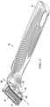
- the shaving razor has a handle 12 and a blade cartridge unit 15 which can releasably attach to the handle 12 and can contain one or more blades 17.
- the description herein relates primarily to the handle 12, and features associated with the handle 12 that facilitate pivoting of the blade cartridge unit 15 relative to the handle 12, and provision of skin benefit delivery components to the skin of a user of the razor 10.
- the skin benefit delivery components extend from handle 12 through an opening in the cartridge unit 15 and can, therefore, be in close proximity to the skin of a user during shaving.
- the benefits will be delivered through a pivoting head as will be described herein.
- the mechanism to pivot the pivoting head relative to a handle comprises a benefit pivot delivery connection, a spring member, and one or more bearings.
- the benefit pivot delivery connection functions to deliver a benefit (such as heat or fluid) from the handle to a user's skin.
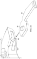
- FIG. 1 Two non-limiting embodiments of razors providing for a skin benefit are disclosed herein.
- the first, shown in FIG. 1 can deliver a fluid to the skin of the user.
- FIG. 2 which shows the underside of the razor depicted in FIG. 1
- a portion of the handle 12 can extend through blade cartridge unit 15 and be exposed as face 80.
- Face 80 can be a skin interfacing surface, intended to be contacting or proximate the skin of a user using the shaver, discussed more fully below.
- face 80 is a surface of a pivoting head 22 and can have openings 78 through which a fluid can be dispensed for skin benefit during and after shaving.
- Pivoting head 22 can pivot about a pivot axis, referred to herein as a pivot axis or a first axis of rotation 26 with respect to handle 12, as well as a secondary axis of rotation 27 that is generally perpendicular to the first axis of rotation 26.
- Fluid flow from the reservoir in handle 12 can be achieved by pressing the skin benefit actuator 14, which can be a depressible button, and which presses on a fluid reservoir inside handle 12 to urge fluid flow toward and through the pivoting head 22, as described more fully below.
- the reservoir may be of any type. One example is described in co-owned, co-pending US Patent Application No. 15/499,307 .
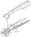
- FIG. 4 shows another embodiment of a shaving razor that has a handle 12 and a blade cartridge unit 15 which can releasably attach to the handle 12 and can contain one or more blades 17.
- the pivoting head 22 can comprise a heat delivery element which can deliver a heat benefit to the skin or a heat skin benefit.
- pivoting head 22 can pivot about the first axis of rotation 26 with respect to handle 12, as well as a secondary axis of rotation 27 that is generally perpendicular to the first axis of rotation 26.
- FIG. 5 which shows the underside of the razor depicted in FIG.
- heating surface 82 is a surface of a pivoting head 22 and can be heated to deliver a heat skin benefit during or after shaving. Heating can be achieved by pressing the skin benefit actuator 14, which can be a depressible button, and which closes a powered circuit inside handle 12 to a flexible circuit to the pivoting head 22, as described more fully below.
- the handle 12 may hold a power source, such as one or more batteries (not shown) that supply power to a heat delivery element, as discussed below.
- the heat delivery element may comprise a metal, such as aluminum or steel.
- the razor handle disclosed herein can include the heat delivery element disclosed co-owned, co-pending US Application having a Docket No. 14532FQ.
- FIG. 7 an embodiment of a handle for a razor providing a fluid skin benefit will be described in more detail. It should be noted that many of the components described in relation to the razor 10 providing a fluid skin benefit can also be incorporated into a razor 10 providing for heat skin benefit, particularly as they relate to the handle and pivoting head described herein, including the shape of the pivoting head, and the spring mechanism that urges the pivoting head into a rest position, and the limit members that limit the range of rotation of the pivoting head, all as described more fully below.
- the handle 12 comprises a main body 16 that can include a main frame 18 and a secondary frame 20.
- the main body 16 including its component main frame 18 and secondary frame 20 members can comprise a durable material such as metal, cast metal, plastic, impact-resistant plastic, and composite materials.
- the main frame 18 can be made of metal and can provide a significant portion of the structural integrity of the handle.
- the main frame 18 is comprised of zinc.
- the main frame 18 is comprised of die cast zinc.
- the secondary frame 20 can be made of a plastic material and can overlie most of the main frame 18 and provide for a significant portion of the size and comfort of the handle 12.
- a pivoting head 22 can be connected to the main body 16 by one or more arms 24. Pivoting head 22 can pivot about the first axis of rotation 26 that is defined by the connection of the pivoting head 22 to pins 30 disposed at distal portions 58 of arms 24, as described more fully below. As discussed above, blade cartridge unit 15 attaches to the pivoting head 22 such that the blade cartridge unit 15 can pivot on handle 12 to provide more skin contact area on the skin of a user during shaving.
- the pivoting head 22 can have a shape beneficially conducive to both attaching to the blade cartridge unit 15 and facilitating the delivery of a skin benefit from the handle 12 to and through the blade cartridge unit 15 attached to the handle 12.
- the shape of the pivoting head 22 can alternatively be described as a "funnel,” or as “tapered,” or a “trapezoidal prism-shaped.” As understood from the description herein, the description "trapezoidal prism” is general with respect to an overall visual impression the pivoting head. For example, a schematic representation of a trapezoidal prism-shaped element is shown in FIG. 8 and shows a shape having a relatively wide upper face (or opening) 32, a relatively narrow lower face 34, two long major faces 36, and two end faces 38 that are generally trapezoidal-shaped.
- trapezoidal prism is used herein as the best description for the overall visual appearance of the pivoting head 22, but the description does not imply any particular geometric or dimensional requirements beyond what is described herein. That is, the pivoting head 22, including the cover member 40, need not have complete edges or surfaces. Further, edges need not be unbroken and straight, and sides need not be unbroken and flat.
- Pivoting head 22 and the various parts as described herein can be made of thermoplastic resins, which can be injection molded.
- the thermoplastic resin can preferably be of a relatively high impact strength with a Charpy notched strength impact value higher than 2 kJ/m 2 (as measured by ISO 179/1).
- the thermoplastic resin can have a relatively high tensile modulus above 500 MPa as measured using ISO 527-2 /1-A (1 mm/min).
- resins of the polyoxymethylene can be utilized for the pivoting head parts, and copolymer forms can be more readily injection molded due to improved heat stability over homopolymer versions.
- Acetal copolymer with Charpy notched strength impact values higher than 6 kJ/m 2 (as measured by ISO 179/1), including with values equal to or greater than 13 kJ/m 2 , and including values greater than 85 kJ/m 2 can be utilized.
- the thermoplastic material is relatively stiff having a tensile modulus above 900 MPa as measured using ISO 527-2 /1-A (1 mm/min). Examples include HOSTAFORM ® XT20 and HOSTAFORM ® S9363.
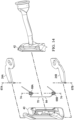
- FIGS. 9-13 shows a pivoting head in side profile in which corresponding faces 32, 34, 36, and 38 of the trapezoidal prism shape in FIG. 8 are shown, the trapezoidal prism shape schematically representing the general shape impression of the pivoting head 22.
- FIG. 9 shows a portion of pivoting head 22 that includes a cover member 40, a base member 42 connected to cover member 40, and arms 24 connected handle 12 and to pivoting head 22 at pivot axis, i.e., first axis of rotation 26.
- a fluid skin benefit can be delivered via a benefit delivery member in the form of a fluid benefit delivery member 76 operatively coupled to base member 42 to permit fluid flow from the fluid delivery member into the pivoting head 22.
- fluid benefit delivery member 76 can include a flexible plastic benefit pivot delivery connection, such as a flexible silicone plastic tube, operatively coupled to a fluid reservoir in the handle 12 and to base member 42 such that upon depressing the skin benefit actuator 14 on handle 12, a fluid, including a lubricating lotion, can be transmitted from inside handle 12 through pivoting head 22, and out of openings 78 on face 80 as shown in FIG. 10 .
- the materials chosen for fluid benefit delivery member 76 can have good chemical resistance to a variety of chemicals found in a consumer environment for durability along with a low modulus of elasticity for providing low resistance to angular deflection about a pivot.
- the materials for fluid benefit delivery member 76 can include thermoplastic elastomers (TPE).
- TPE materials can include styrenic block copolymers, including, for example, Poly(styrene-block-ethylenebutylene-block-styrene) (SEBS), Poly(styrene-block-butadiene-block-styrene) (SBS), or Poly(styrene-block-isoprene-block-styrene) (SIS).
- SEBS Poly(styrene-block-ethylenebutylene-block-styrene)
- SBS Poly(styrene-block-butadiene-block-styrene)
- SIS Poly(styrene-block-isoprene-block-styrene)
- the materials for fluid benefit delivery member 76 can include thermoplastic vulcanized (TPV) systems.
- the fluid delivery member can be injection molded as an overmold, e.g., in a two-shot injection molding operation, on base member 42 which can be a different material, including a relatively harder plastic.
- base member 42 which can be a different material, including a relatively harder plastic.
- fluid benefit delivery member 76 can also be formed separately and joined to base member 42.
- Suitable TPV systems can include TPV systems based on polypropylene (PP) and ethylene propylene diene terpolymer (EPDM), TPV systems based on polypropylene and nitrile rubber, TPV systems based on polypropylene and butyl rubber, TPV systems based on polypropylene and halogenated butyl rubber, TPV systems based on polypropylene and natural rubber, or TPV systems based on polyurethane and silicone rubber.
- a TPV system based on polypropylene can have the greater chemical resistance against chemicals commonly used in shaving applications.
- materials for the fluid benefit delivery member 76 can include creep resistant materials having an increase in tensile strain of less than about 3% from an initial tensile strain when measured using ISO 89901 carried out at 1000 hours at 73 Fahrenheit.
- materials for the fluid benefit delivery member 76 can include materials having a hardness of about 10 on a Shore A durometer scale and about 60 on a Shore A durometer scale.
- the materials for any benefit delivery member, such as the fluid benefit delivery member 76 or heat delivery member 96 can be below 60A, including values below 50A.
- materials for the fluid benefit delivery member 76 can include elastomers having compression sets less than about 25% as measured by ASTM D-395.
- benefit delivery member has a moment of inertia from about 6 mm 4 to about 40 mm 4 .
- TPU thermoplastic polyurethane
- MPR melt processable rubber
- PVC plasticized polyvinyl chloride
- OBC olefinic block copolymers
- ionomers thermoplastic elastomers based on styrenic block copolymers.
- One or both ends 44 (corresponding to the end faces 38 of the schematic shape shown in FIG. 8 ) of the pivoting head 22 can have a limit member 46 that limits the extent of rotation of pivoting head 22 about first axis of rotation 26.
- limit members 46 limit rotation by providing a surface of the pivoting head 22 that can come into contact with arms 24 to stop rotation.
- the limit members can include first and second surfaces 48, 50 that can come into contacting relationship with arms 24 to stop rotation of the pivoting head about first axis of rotation 26.
- surfaces 48, 50 can be diverging surfaces that diverge relative to each other from a closest position near the pivoting axis 26 a distance substantially the extent of the portion of pivoting head 22 corresponding to the short dimension of the major faces 36 of the trapezoidal prism shape.
- first diverging surface 48 can limit movement of the pivoting head to a first position and the second diverging surface 50 can limit the movement of the pivoting head to a second position. Pivoting of the pivoting head 22 is thus limited by the interaction of the diverging surfaces and the arms 24.
- First and second diverging surfaces 48, 50 can be flat, partially flat, or have non-flat portions, with the only requirement being that a portion of the diverging surfaces contact arm 24 to limit rotation as desired.
- first diverging surface 48 of limit member 46 can be substantially flat and can be disposed in contacting relationship adjacent arm 24 to limit the pivoting head 22 from further pivoting in a counterclockwise direction (as viewed in FIG. 9 ).
- the included angle 43 between the diverging surfaces (e.g., an angle of divergence) for the angularly diverging surfaces 48 and 50 can determine the angular rotation of pivoting head 22 about first axis of rotation 26.
- the angle of divergence for the angularly diverging surfaces 48 and 50 can be up to 50 degrees or more.
- pivoting head 22 can rotate from a first position at 0 degrees to a second position at about 50 degrees relative to the first position, and any position therebetween.
- a spring member 64 can apply a biasing force at a location corresponding to a main bar portion axis 86, as described more fully below, to urge pivoting head 22 toward the first, at rest, position.
- the position shown in FIG. 9 can be considered a rest position, as this is the position of the pivoting head 22 when no biasing force is applied against spring member 64 (shown in FIG. 13 ) to rotate the pivoting head clockwise (as viewed in FIG. 9 ).
- the rest position of the pivoting head can be at any angle within the included angle 43.
- pivoting head 22 is shown connected to the main frame 18 of the main body 16 by arms 24, referred to individually as first arm 24A and second arm 24B.
- the nomenclature of "A" and “B” is used herein to denote individual pairs of elements.
- Fluid benefit delivery member 76 extends from main body 16 and connects to base member 42, which is joined to cover member 40 to provide for controlled fluid transport from a reservoir inside handle 12 to one or more openings 78 on the face 80 of pivoting head 22.
- face 80 can extend through an opening on an attached blade cartridge unit 15 such that face 80 can be disposed very near, or even on, the skin of a user when razor 10 is used for shaving.
- Fluid flow can be provided, for example, by pressure applied to a flexible fluid reservoir inside handle 12. Pressure can be applied, for example, by the user pressing on a skin benefit actuator 14 on handle 12.
- a proximal portion 52 of arms 24 can be connected to the main frame 18 at a mounting location 60.
- Arms 24 can be made of metal and the main frame can be made of metal such that a relatively strong connection can be facilitated by the fixation of metal arms on a metal main frame.
- Proximal portion 52 of arm 24 can define an opening 54 (shown in more detail in FIG. 12 ) in arm 24 which can engage a protuberance 56 on main frame 18 for connection to main body 16 of handle 12.
- Arms 24 likewise have a distal portion 58 which can engage a bearing recess 62 in pivoting head 22 (described more fully below) for connecting the pivoting head 22 to the main body 16 of handle 12.
- a first arm 24A can have a first proximal portion 52A that can define an opening 54A that can connect to a first protuberance 56A at a first location 60A on main frame 18, and a second arm 24B can have a second proximal portion 52B that can define an opening 54B that can connect to a second protuberance 56B at a second location 60B on main frame 18.
- a first arm 24A can have a first distal portion 58A that can connect to a first bearing recess in pivoting head 22, and a second arm 24B can have a second distal portion 58B that can connect to a second bearing recess in pivoting head 22.
- Pivoting head 22 can have mating portions that when connected together form a spring-loaded compartment 84 therebetween, the compartment facilitating the delivery of a skin benefit to a user during shaving.
- pivoting head 22 can have a cover member 40, a base member 42 connected to cover member 40, and arms 24 connecting the pivoting head 22 to main body 16.
- arms 24 can have pins 30 disposed at distal portions 58 thereof.
- cylindrical pins 30 can be welded to distal portions 58 of arms 24.
- Each pin 30 can be operatively disposed in a bearing recess 62 on pivoting head 22.
- the bearing recess 62 can be a cylindrical opening on cover member 40 having an inside diameter slightly greater than the outside diameter of pins 30, such that cover member 40, and therefore pivoting head 22, can freely pivot upon the first axis of rotation 26.
- a spring member 64 is partially disposed between the mating faces of the cover member 40 and base member 42 and acts to bias the pivoting head 22 in relation to arms 24 into the first position as shown in FIG. 4 , in which first diverging surface 48 of limit member 46 rests in contacting relationship with arm 24.
- Spring member 64 can be any spring member facilitating biasing of the pivoting head to the first rest position.
- Spring member can be, for example, any of torsion coil springs, coil spring, leaf spring, helical compression spring, and disc spring.
- spring member 64 comprises torsion springs, and can have at least one coil spring 68.
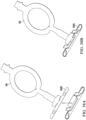
- two coil springs 68A and 68B are coupled together in a spaced relationship by a main bar portion 70 as shown in FIG. 14 .
- coil springs 68 can each define a longitudinal coil axis 74.
- the axis of rotation which can be called a pivot axis or a first pivot axis, can be parallel to and offset from one of the longitudinal coil axes.
- spring member 64 can be can be made of plastic, impact-resistant plastic, metal, and composite materials.
- the spring member 64 can be made from materials that are resistant to stress relaxation such as metal, polyetheretherketone, and some grades of silicone rubber.
- Such an embodiment of spring member 64, comprised of stress relaxation resistant materials, can prevent the pivot head from undesirably taking a "set," a permanent deformation of the spring member that prevents the pivot head from returning to its rest position when unloaded.
- spring member 64 can be made of 200 Series or 300 Series stainless steel at spring temper per ASTM A313.
- spring member 64 can be comprised of stainless steel wire (e.g., 302 stainless steel wire) having an ultimate tensile strength metal greater than 1800 MPa or an engineering yield stress between about 800 MPa and about 2000 MPa.
- First arm 24A and second arm 24B can each be generally flat members having generally parallel planar opposite sides.
- Arms 24 can define an imaginary plane 66, as shown in FIG. 9 , and the imaginary plane 66A of arm 24A can be coplanar with the imaginary plane 66B of arm 24B.
- Pins 30 can each have an imaginary longitudinal pin axis 68 disposed centrally in relation to each pin, and imaginary longitudinal pin axis 68A of pin 30A on arm 24A can be coaxial with longitudinal pin axis 68B of pin 30B on arm 24B, as indicated in FIG. 14 .
- Arms 24 can have various shapes and features beneficially adapted to the pivoting head 22. Additionally, arms can be made of plastic, impact-resistant plastic, metal, and composite materials. In an embodiment, arms 24 can be comprised of metal. Arms 24 and can be made of a 200 or 300 Series stainless steel having an engineering yield stress measured by ASTM standard E8 greater than about 200 MPa, and preferably greater than 500 MPa and a tensile strength again measured by ASTM standard E8 greater than 1000 MPa.
- arms 24 can be sized and shaped appropriately to the size of the pivoting head 22 and handle 12 to which pivoting head 22 is attached.
- arm 24 can be considered in plan view having an arm length, Al, of from about 10 mm to about 25 mm, and can be about 17 mm.
- arm 24 can have an arm width, Aw, of from about 5mm to about 20 mm, and can be about 10 mm.
- arm 24 can be a substantially uniform thickness plate having an arm thickness, At, of from about 0.5 mm to about 4 mm, and can be about 1 mm.
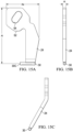
- arm 24 can be substantially flat in side profile, as shown in FIGS. 15A and 15B . In an embodiment, arm 24 can have at least one bend as shown in side profile in FIGS. 15B and 15C .
- a pin 30 can be integral with arm 24, or attached, such as by welding, to arm 24 such that a portion 30C of pin 30 extends laterally to engage the bearing recess 62 of the pivoting head 22.
- Pin 30 can be a circular cross section cylindrical shape having a length of from about 2 mm to about 15 mm and can be about 4 mm. Pin 30 can have a largest cross-sectional dimension, such as a diameter, of from about 0.6 mm to about 2.5 mm, and can be about 1.0 mm.
- Perimeter of holes in arm can be from about 5 mm to about 25 mm and can be about 10 mm.
- the arms have a minimum cross-sectional moment of inertia multiplied by the elastic modulus of the arm material greater than 65 N-cm 2 .
- this minimum cross-sectional moment of inertia multiplied by the elastic modulus of the arm material can be about 400 N-cm 2 to about 20000 N-cm 2 .
- arm 24 can have portions at a proximal portion 52 defining an opening 54. Openings can be used to engage and attach arms 24 to the main body 16.
- arm 24 shown in FIG. 15 corresponds to arm 24 shown in FIGS. 10 and 11 , in which opening 54 engages a protuberance 56 on main frame 18 of main body 16.
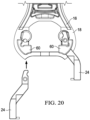
- FIGS. 17-20 show alternative embodiments of arms 24.
- arms 24 can have a variable thickness At, and can have a thicker portion generally central to arm 24 and thinner portions near the ends of arm 24. Such a configuration can permit optimization of strength and weight of arms 24.
- FIGS. 18 and 20 show alternative connection embodiments in which a hook member on the proximal portion 52 of arm 24 can engage a mating portion of main body 16.
- Pivoting head 22 can be rotated about first axis of rotation 26 by a biasing force applied to the pivoting head to rotate the pivoting head 22 about the first axis of rotation 26 to a second position such that second diverging surface 50 rests in contacting relationship with arm 24.
- spring member 64 can act to rotate pivoting head back to the first position.
- pivoting head 22 can be rotated about the first axis of rotation 26, which can be considered a first pivot axis, from the first position through an angle of rotation of between about 0 degrees and about 50 degrees and when rotated the pivot spring applies a biasing torque about the first axis of rotation 26 of less than about 30 N-mm at an angle of rotation of about 50 degrees.
- pivoting head 22 can be rotated about the first axis of rotation 26, which can be considered a first pivot axis, from the first position through an angle of rotation of between about 0 degrees and about 50 degrees and when rotated the pivot spring applies a biasing torque about the first axis of rotation 26 of between about 2 N-mm and about 12 N-mm.
- the fluid benefit delivery member 76 being flexibly coupled can provide a portion of the restorative, biasing torque as well.
- the fluid delivery member can contribute about 30% of the restorative, biasing torque about the first axis of rotation 26.
- the restorative, biasing torque about the first axis of rotation 26 can be about less than about 10 N-mm and can be about 6 N-mm with about 4.5 N-mm contributed by spring member 64 and about 1.5 N-mm contributed by the fluid benefit delivery member 76.
- the pivoting torque supplied by the spring member can be considered a first pivoting torque.
- the pivoting torque supplied by the benefit delivery member can be considered a second pivoting torque.
- the benefit delivery member can be severable, that is, cut, removed, or otherwise uncoupled from its ability to supply a pivoting torque to the pivoting head.
- a ratio of the sum of said first and second pivoting torques divided by said angular deflection in radians to said second pivoting torque divided by said angular deflection in radians of said pivoting head with said pivot benefit delivery connection severed is greater than 2 and can be greater than 4.
- Torque can be measured according to the Static Torque Stiffness Method described below in the Test Methods section.
- spring member 64 can be a torsion spring and can include a first coil spring 69A and a second coil spring 69B coupled by a main bar portion 70.
- a leg extension 72 can extend from each coil spring 69 a sufficient length to operatively engage arms 24 to provide the biasing force necessary to cause pivoting head 22 to be urged toward the first, rest, position.
- spring member 64 applies a resisting, restorative force to urge the pivoting head back to the first position.
- Coil springs 69A and 69B can each define a longitudinal coil axis 74.
- Longitudinal coil axis 74A of first coil spring 68A can be coaxial with longitudinal coil axis 74B of second coil axis 68B.
- One or both of longitudinal axes 74 can be substantially parallel to and offset from the first axis of rotation 26, which can be referred to as a pivot axis.
- Spring member 64 can be made of metal, including steel, and can be stainless steel having an engineering yield stress greater than about 600 MPa.
- coil springs 69 are operatively disposed on each end of pivoting head 22 and a portion of the main bar portion 70 resides between the cover member 40 and base member 42 to provide direct engagement to bias the pivoting head toward a rest position.
- the first axis of rotation 26 can be parallel to and offset from both of the longitudinal coil axes 74A, 74B, and can, as well, be parallel to and offset from the main bar portion axis 86.
- the first axis of rotation 26 can be parallel to and offset from both of the longitudinal coil axes 74A, 74B a distance of from about 1 mm to about 5 mm.
- the first axis of rotation 26 can be parallel to and offset from both of the longitudinal coil axes 74A, 74B a distance of about 2 mm.
- spring member can be made of materials including amorphous polymers with glass transition temperatures above 80 Celsius, metals, elastomers having compression sets less than 25% as measured by ASTM D-395 and combinations thereof.
- spring member comprises creep resistant materials having an increase in tensile strain of less than about 3% from an initial tensile strain when measured using ISO 89901 carried out at 1000 hours at 73 Fahrenheit.
- FIGS. 22-24 illustrate an embodiment of a base member 42 having at least one channel 87 disposed on a face thereof.
- base member 42 includes a channel 87 for housing a portion of spring member 64.
- the embodiment illustrated in FIGS. 22-24 includes a fluid benefit delivery member 76, but with respect to the channel 87 the base member 42 need not be coupled to the fluid benefit delivery member 76, but could, instead, house components related to a heating surface 82, as described in more detail below.
- Base member 42 can be molded plastic, and channel 87 can be a molded channel.
- fluid deliver member 76 can be molded flexible plastic and can be molded integrally with base member 42.
- Channel 87 can have a size and shape conformed to receive the main bar portion 70 of spring member 64, as shown in FIGS. 21-24 .
- FIG. 22 shows spring member 64 prior to being inserted into channel 87;
- FIG. 23 shows spring member 64 placed into channel 87 with first and second coil springs 68A and 68B disposed at an exterior portion of base member 42.
- cover member 40 also made of molded plastic and made to have mating surfaces with base member 42 can be joined by translating onto and connecting to the base member in the direction indicated by arrows in FIG. 24 .
- cover member 40 Once cover member 40 is in mating relationship with base member 42, cover member and base member can be joined, such as by adhesive, press fit, or welding.
- staking pins 89 can be driven into openings 90 in a cold press fit as shown in FIGS. 25 and 26 to cause the base member 42 and cover member 40 to remain in operatively stable mating relationship.
- a compartment 84 is defined between the parts, which compartment 84 has a volume into which fluid can flow from the handle 12 and from which fluid can flow to openings 90 on the skin interfacing face 80 of pivoting head 22.
- Fluid containment in compartment 84 can be achieved by a sealing relationship between cover member 40 and base member 42.
- FIG. 27A shows the mating surface of a cover member 40 and
- FIG. 27B shows the first mating surface 88 of a base member 42.
- sealing can be achieved by the first mating face 88 of cover member 40 that, when operatively connected to base member 42 can mate in a juxtaposed, contacting relationship with a second mating face 90 of base member 42.
- a gasket member 92 can extend outwardly from first mating face 88 and can sealingly fit in a corresponding gasket groove 94 on base member 42.
- FIGS. 28-33 An embodiment of a pivoting head 22 can be assembled onto handle 12 in a manner illustrated in FIGS. 28-33 .
- pins 30 of arms 24 can be inserted into bearing recess 62 of cover member 40 by translating in the direction of the arrow of FIG. 28 , which direction aligns with the longitudinal pin axis 67 (as shown in FIG. 14 ) and first axis of rotation 26.
- spring member 64 is disposed in operative relationship between cover member 40 and base member 42.
- Arms 24 can be held in place in any suitable manner while they are slid in the direction of the arrows in FIG. 30 , which shows before (A) and after (B) depictions of the arm securement in slots 103 of main body 16.
- openings 54 of arms 24 can be exposed through a corresponding access opening 106 in main body 16.
- one or more extensions 107 on or in slot 103 can provide for an interference fit to hold arms in place for the next step.
- FIG. 33 there is shown certain handle 12 elements being assembled to secure pivoting head 22 to handle 12.
- An embodiment of main frame 18 is shown translating in the direction of the arrows in FIG. 33 from a first position (A) to join secondary frame 20 (B).
- Main frame 18 can be joined to secondary frame 20 by adhesive applied at adhesive grooves 120 on secondary frame 20 which can mate with corresponding adhesive bosses on main frame 18.
- Main frame 18 can be disposed on a portion of secondary frame 20 in a mating relationship such that protuberances 56 are inserted through access openings 106 of main body 16 and openings 54 of arms 24.
- Protuberances 56 can provide positive metal-to-metal coupling of arms 24 to handle 12.
- adhesive can be applied at the connection of protuberances 56 and openings 54 to provide for additional securement of arms (and, therefore, pivoting head 12) to main frame 18 (and, therefore, handle 12).
- Pivoting head 22 for delivering heat can have components common to those described above for delivering fluid, such as one or more arms 24, one or more spring members 64, a cover member 40 and a base member 42, and these common components can be configured as described above, or in a similar manner.
- the pivoting head 22 for delivering a heat benefit can also have a heat delivery member 96 comprised of heat delivery components, including a flexible conductive strip 98 for conducting electricity from a first proximal portion 98A operatively attached in handle 12 to a second distal portion 98B operatively disposed in pivoting head 22 and delivering heat to the skin at a heating surface 82.
- a heat delivery member 96 comprised of heat delivery components, including a flexible conductive strip 98 for conducting electricity from a first proximal portion 98A operatively attached in handle 12 to a second distal portion 98B operatively disposed in pivoting head 22 and delivering heat to the skin at a heating surface 82.
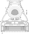
- FIG. 35 shows an embodiment of a pivoting head 22 for a razor delivering a heat skin benefit.
- the pivoting head can include a cover member 40 connected to a base member 42 and a spring member 64 partially disposed between the cover member 40 and the base member 42.
- the pivoting head 22 shown in FIG. 35 can include components shown in the assembly view of FIG. 36 .
- spring member 64 as described above can be disposed between the cover member 40 and the base member 42, substantially as described above.
- Other components can be disposed on the outside of cover member 40 and can be attached in a layered relationship having sizes that correspond to the narrow lower face of the cover member 40.
- the heat delivery member 96 may include a face plate 102 for delivering heat to or proximal to the skin's surface during a shaving stroke for an improved shaving experience.
- the face plate 102 may have an outer skin contacting heating surface 82 comprising a relatively hard coating (that is harder than the material of the face plate 102), such as titanium nitride to improve durability and scratch resistance of the face plate 102.
- a relatively hard coating that is harder than the material of the face plate 102
- the face plate 102 may go through an anodizing process.
- the hard coating of the skin contact surface may also be used to change or enhance the color of the skin application surface 82 of the face plate 102.
- the heat delivery element 96 may be in electrical communication with a portion of the handle 12. As will be described in greater detail below, the heat delivery element 16 may be mounted to the pivoting head 22 and in communication with the power source (not shown).
- the face plate 102 may be as thin as possible, but stable mechanically.
- the face plate 102 may have a wall thickness of about 100 micrometers to about 200 micrometers.
- the face plate 102 may comprise a material having a thermal conductivity of about 10 to 30 W/mK, such as steel.
- the face plate 102 can be manufactured from a thin piece of steel that results in the face plate 102 having a low thermal conductivity thus helping minimize heat loss through a perimeter wall 110 and maximizes heat flow towards the skin interfacing surface 80.
- the face plate 102 may be constructed from a thicker piece of aluminum having a thermal conductivity ranging from about 160 to 200 W/mK.
- the heat delivery element 96 may include a heater (not shown), e.g., a resistive heat element portion of flexible conductive strip 98, that is in electrical contact with a micro-controller and a power source (not shown), e.g. a rechargeable battery, positioned within the handle 12.
- the heat delivery member 96 may include the face plate 102, the flexible conductive strip 98 heater, a heat dispersion layer 100, a compressible thermal insulation layer 99, and a portion of cover member 40.
- the face plate 102 may have a recessed inner surface 122 opposite the skin application surface 82 configured to receive the heater 98, the heat dispersion layer 100 and the compressible thermal insulation layer 99.
- the perimeter wall 110 may define the inner surface 122.
- the perimeter wall 110 may have one or more tabs 108 extending from the perimeter wall 110, transverse to and away from the inner surface 122. For example, Fig. 36 illustrates four extending from the perimeter wall 110.
- the heat dispersion layer 100 may be positioned on and in direct contact with the inner surface 122 of the face plate 102.
- the heat dispersion layer 100 may have a lower surface 124 directly contacting the inner surface 122 of the face plate 102 and an upper surface 126 (opposite lower surface 37) directly contacting the heater 98.
- the heat dispersion layer 100 can be defined as a layer of material having a high thermal conductivity and can be compressible.
- the heat dispersion layer 100 may comprise graphite foil.
- the heat dispersion layer 100 may have an anisotropic coefficient of thermal conductivity in the plane parallel to the face plate 102 of about 200 to about 1700 W/mK (preferably 400 to 700 W/mK) and vertical to the face plate 102 of about 10 to 50 W/mK and preferably 15 to 25 W/mK to facilitate sufficient heat conduction or transfer.
- the compressibility of the heat dispersion layer 100 allows the heat dispersion layer 100 adapt to non-uniform surfaces of the inner surface 122 of the face plate 102 and non-uniform surfaces of the heater 98, thus providing better contact and heat transfer.
- the compressibility of the heat dispersion layer 100 also minimizes stray particulates from pushing into the heater 98 (because the heat dispersion layer 100 may be softer than the heater), thus preventing damage to the heater 98.
- the heat dispersion layer 100 may comprise a graphite foil that is compressed by about 20% to about 50% of its original thickness.
- the heat dispersion layer 100 may have a compressed thickness of about 50 micrometers to about 300 micrometers more preferably 80 to 200 micrometers.
- the heater 98 may be positioned between two compressible layers.
- the heater 98 may be positioned between the heat dispersion layer 100 and the compressible thermal insulation layer 99.
- the two compressible layers may facilitate clamping the heater 98 in place without damaging the heater 98, thus improving securement and assembly of the heat delivery element 96.
- the compressible thermal insulation layer 99 may help direct the heat flow toward the face plate 102 and away from the cover member 40. Accordingly, less heat is wasted, and more heat may be able to reach the skin during shaving.
- the compressible thermal insulation layer 99 may have low thermal conductivity, for example, less than 0.30 W/mK and preferably less than 0.1 W/mK.
- the compressible thermal insulation layer 38 may comprise an open cell or closed cellular compressible foam.
- the compressible thermal insulation layer 99 may be compressed 20-50% from its original thickness.
- the compressible thermal insulation layer 99 may have a compressed thickness of about 400 ⁇ m to about 800 ⁇ m.
- the cover member 40 may be mounted on top of the compressible thermal insulation layer 99 and secured to the face plate 102. Accordingly, the heater 98, the heat dispersion layer 100 and the compressible thermal insulation layer 99 may be pressed together between the face plate 102 and the cover member 40 and assembled as described more fully below.
- the heat dispersion layer 100, the heater 98, and the compressible thermal insulation layer 99 may fit snugly within the perimeter wall 110.
- the pressing of the various layers together may result in more efficient heat transfer across the interfaces of the different layers in the heat delivery element 96. In absence of this compression force the thermal transfer across the interfaces can be insufficient. Furthermore, the pressing of the layers together may also eliminate secondary assembly processes, such as the use of adhesives between the various layers.
- the compressible thermal insulation layer 99 may fit snugly within the perimeter wall 110.
- the first layer in contacting relationship with cover member 40 can be a compressible thermal insulation layer 99 such as a foam member.
- a portion of the heater in the form of a flexible conductive strip 98 can be sandwiched between a foam thermal insulation layer 99 and a graphite foil strip heat dispersion layer 100.
- the layers of foam thermal insulation layer 99, flexible conductive strip 98 and graphite foil strip can be connected in layered, contacting relationship to the narrow lower face of the cover member 40 by a faceplate 102.
- Faceplate 102 can have a smooth outer surface that corresponds to heating surface 82, and tabs 108 that can be used to connect the heat delivery components to the pivoting head 22.
- a graphite foil strip heat dispersion layer 100 can be placed onto a trough 104 of faceplate 102, such as onto the recessed inner surface 122 of faceplate 102.
- distal portion 98B of flexible conductive strip 98 can be shaped and fit into the trough 104 of faceplate 102.
- a compressible thermal insulation layer 99 member can be placed into trough 104 of faceplate 102.
- foam thermal insulation layer 99 can be sized and shaped accordingly to fit in trough 104.
- cover member 40 can be placed on top of the other layered components in and faceplate 102.
- cover member 40 can be secured to the cover member 40 via tabs 108 as shown in the assembly view of FIG. 41 A-D .
- tabs 108 including a pair of tabs labeled 1 and 2 in FIG. 41A and 3 and 4 in FIG. 41B , can be folded into receiving openings 111 on cover member 40, as shown in the cross-sectional perspective assembly view of FIG. 41C and 41D .
- spring member 64 as described above, can be placed in cover member 40 and seated in corresponding form-fitting recesses, including a channel 87, of cover member 40.
- base member 42 can be connected to cover member in a sequence described with respect to the assembly view of FIG. 43 A-F .
- one or more first latching members 112 on base member 42 can be placed into and hooked into one or more first latch receiving portions 114 of cover member 40, and, as shown in FIG. 43 C-F , base member 42 can be rotated and pressed onto cover member 40 such that one or more second latching members 116 can be snapped into cooperating second latch receiving portions 118.
- pivoting head 22 is ready to be coupled to handle 12.
- arms 24 can be inserted in the direction of the arrows into the bearing recess 62 of cover member 40 by sliding pins 30 into the bearing recesses 62, as described above.
- arms 24 can then be inserted in the direction of arrows into slots 103 of main body 16.
- a slot 103 is shown having disposed therein the proximal portion of arm 24 as well as a leg extension 72 of spring member 64.
- portions of main body 16 can be cold stamped in the direction of the arrows to secure arms 24 to main body 16 of handle 12.
- portions of the main body 16 corresponding to openings 54 of arms 24 can be permanently plastically deformed by pressing into the openings 54. This operation, known as cold stamping or cold staking, permits secure coupling of arms 24, and therefore, pivoting head 22, to main body 16 (and, therefore, handle 12).
- pivoting head 22 can be pivoted about a pivot axis, i.e., axis of rotation 26 under the biasing force of a spring member 64.
- pivoting head 22 can be in pivotal relation to the handle 12 via, for example, a spring, a joint, a hinge, a bearing, or any other suitable connection that enables the pivoting head to be in pivotal relation to the handle.
- the pivoting head may be in pivotal relation to the handle 12 via mechanisms that contain one or more springs and one or more sliding contact bearings, such as a pin pivot, a shell bearing, a linkage, a revolute joint, a revolute hinge, a prismatic slider, a prismatic joint, a cylindrical joint, a spherical joint, a ball-and-socket joint, a planar joint, a slot joint, a reduced slot joint, or any other suitable joint, or one or more springs and one or more rolling element bearings, such as a ball bearing, a cylindrical pin bearing, or rolling element thrust bearing.
- Sliding contact bearings can typically have friction levels of 0.1 to 0.3.
- Rolling element bearings can typically have friction of 0.001 to 0.01. Lower friction bearings are preferred the further a pivot mechanism is offset from its axis of rotation to assure smooth motion and prevent the bearing from sticking.
- pivot mechanisms about first axis of rotation 26 allow rotational motions ranging from about 0 degrees from the cartridge rest position to about 50 degrees.
- a rotational stiffness for a pivot mechanism about first axis of rotation 26 may be measured by deflecting the pivot 25 degrees about the first axis of rotation 26 and measuring the required torque about this first axis of rotation 26 to maintain this position.
- the torque levels at 50 degrees of rotation can be generally less than 20 N-mm.
- the rotational stiffness (torque measured about the axis of rotation divided by degrees of angular rotation) associated with the first axis of rotation 26 can be generally less than 0.3 N-mm per degree of rotation and preferably between 0.05 N-mm per degree of rotation and 0.18 N-m per degree of rotation.
- additional pivot mechanisms about secondary axis of rotation 27 allow rotational motions ranging from -12.5 degrees to +12.5 degrees.
- a rotational stiffness for a pivot mechanism about secondary axis of rotation may be measured by deflecting the pivot -5 degrees and +5 degrees about secondary axis of rotation 27 and measuring the required torques about the secondary axis of rotation to maintain this position. The rotational stiffness may be calculated by dividing the absolute value of the difference in these measured torques by the 10 degrees difference in angular motion.
- the rotational stiffness associated with pivot mechanisms about secondary axis of rotation 27 generally range from about 0.8 to about 2.5 N-mm per degree of rotation.
- the handle 12 was connected to the pivoting head 22 by a pair of arms 24, a spring member 26, and a benefit pivot delivery connection.
- the spring member can be comprised of a metal.
- the spring member 64 can also be comprised of a stress-relaxation resistant material such as a metal, polyetheretherketone, or silicone rubber, all of which can prevent the razor 10 or razor handle 12 from taking a "set,” or permanently deforming at deflected angle when the razor 10 or razor handle 12 is stored improperly due to the stress relaxation of the components that connect the pivoting head 22 to the proximal end of the handle.
- the benefit pivot delivery connection can be a connection through which a skin deliver benefit component passes from the handle 12 to the pivoting head 22 to deliver a skin benefit through the cartridge 15 to the skin interfacing face 80.
- a fluid benefit delivery member 76 and a heat delivery member 96 can be configured so as to facilitate proper pivoting of the pivoting head about first axis of rotation 26 and secondary axis of rotation 27.
- a razor 10 is shown in which the flexible conductive strip 98 of heat delivery member 96 bridges a gap between the handle 12 and the pivoting head onto which is attached a blade cartridge 15.
- the flexible conductive strip 98 is longer than the distance to be traversed between the handle 12 and the pivoting head 22, resulting in a loop 150 of the flexible conductive strip 98.
- This loop 150 which can be generally U-shaped or S-shaped, can minimize the effect of the flexible conductive strip 98 on the biasing torque force required to pivot the pivoting head 22 about the first axis of rotation 26.
- this loop 150 of the benefit delivery member contributes to a ratio of biasing torque provided by the sum of the benefit member and the spring member 64, and the biasing torque provided by the spring member alone, which torque ration is discussed in more detail below.
- a fluid delivery benefit member such as a flexible plastic tube
- a fluid delivery benefit member can also have a loop 150 portion such that excess length of the flexible tube allows for minimizing the effect of the fluid benefit delivery member 76 on the biasing torque force required to pivot the pivoting head 22 about the first axis of rotation 26.
- the installed length of fluid benefit delivery member 76 as shown in FIG. 53 can be from 1 mm to 3 mm less than the free length of the fluid benefit delivery member 76. This forced compression contributes to the loop 150 portion and has been found to aid in further minimizing the effect of the fluid benefit delivery member 76 on the biasing torque force required to pivot the pivoting head 22 about the first axis of rotation 26.
- FIGS. 53-61 Additional features found to further minimizing the effect of the fluid benefit delivery member 76 on the biasing torque force required to pivot the pivoting head 22 about the first axis of rotation 26 can be understood with reference to FIGS. 53-61 .
- the radius of curvature can be understood to reduce the stress applied to the surface of the fluid delivery member at the point of bending due to the pivoting of pivoting head 22 during use.
- a chamfer 154 is provided, as shown.
- the chamfer can have a chamfer angle of about 5 degrees to about 30 degrees at the proximal end of the handle, and can have a chamfer length of about 3 mm to about 15 mm.
- the chamfer 154 is believed to reduce the stress applied to the surface of the fluid delivery member at the point of bending due to the pivoting of pivoting head 22 during use.
- a chamfer can be defined as shown in the view of FIG. 54A-C .
- a block 201 is shown with an edge 205 to be chamfered and a front face 206.
- block 201 is shown after edge 205 has been chamfered creating chamfer 202.
- chamfer 202 is shown having a chamfer length 204 and a chamfer angle 203.
- the torque associated with a pivot benefit delivery member can be reduced by cutout in the surrounding structure of the pivoting benefit delivery member that is a chamfer with a chamber angle between about 5 degrees and 30 degrees and chamfer length from 3mm to 15 mm.
- an additional feature found to minimize the effect of the fluid benefit delivery member 76 on the biasing torque force required to pivot the pivoting head 22 about the first axis of rotation 26 can be understood from FIG. 55 as a slot 156 on the handle 12 at the location of the exit of the fluid benefit delivery member 76.
- the slot can have a width measured generally parallel to the axis of rotation 26 of about 3 mm to about 10 mm, and a length measured perpendicular to the width of from about 2 mm to about 15 mm.
- fluid benefit delivery member 76 which can be a flexible molded plastic tube, can be configured such that a distal portion 160 has a thinner wall diameter than a proximal portion 162.
- the proximal portion 162 which can be connected in fluid communication with other components in the handle 12 (not shown), can have a diameter and/or wall thickness that provides for durability and greater physical integrity during manufacture and use.
- distal portion 160 which connects to the cover member 42 of the pivoting head, can comprise a relatively smaller diameter or a relatively thinner wall thickness, thereby providing for greater flexibility and less effect on the biasing torque force required to pivot the pivoting head 22 about the first axis of rotation 26.
- fluid benefit delivery member 76 is shown in which the tube wall of the fluid benefit delivery member 76 is ribbed or corrugated. It is believed that such a design, by permitting much of the wall to be relatively thinner, can, when joined to the base member 42 provide for greater flexibility and less effect on the biasing torque force required to pivot the pivoting head 22 about the first axis of rotation 26.
- FIGS. 58-60 Alternative embodiments of fluid benefit delivery member 76 utilizing coil springs to reinforce strength and provide for flexibility are depicted in FIGS. 58-60 .
- a coil spring 164 which can be made of plastic or metal, can configured about the outside of fluid benefit delivery member 76.
- a coil spring 164 which can be made of plastic or metal, can configured about the inside of fluid benefit delivery member 76.
- a coil spring 164 which can be made of plastic or metal, can configured to be molded into the walls of fluid benefit delivery member 76.
- FIG. 61 depicts one embodiment of a feature to join fluid deliver member 76 to the base member 42.
- a ball and socket joint component 166 can be present on the base member 42.
- the distal end of a tubular fluid delivery member can be joined by pressing or gluing onto the receiving end of the ball and socket joint component 166.
- the joining of the fluid benefit delivery member 76 to the pivoting head 22 can be a two-component embodiment, as shown in FIG. 62 .
- the fluid benefit delivery member 76 can be molded with an integral pivoting head connection member 170 that can attach to the mating portion of the pivoting head 22 in any suitable manner, such as snap fit, friction fit, adhesive joining, or the like.
- a spring member 64 (not shown) can be added externally to the pivoting head 22 to provide for a biasing force on pivoting head.
- the fluid benefit delivery member 76 and the base member 42 of the pivoting head 22 can be overmolded in a two-shot injection mold to form a three-component assembly that can form pivoting head 22.
- the base member can be a relatively hard material and the fluid benefit delivery member 76 can be a relatively soft material.
- a portion of the polymer injection molded for the fluid delivery member forms the gasket member 92 of the base member 42, as described above. Referring to FIG. 63 , the base member 42 and fluid benefit delivery member 76 are shown as they would appear if they were injection molded separately.
- the fluid benefit delivery member 76 and the base member 42 can be overmolded in a two-shot injection mold process to manufacture an integral member as shown in FIG.
- FIG. 65 shows another perspective view of the first mating surface 88 of the cover member 42 having exposed and extended therefrom a gasket member 92 which is integral with fluid benefit delivery member 76.
- the base member can be joined to the third component, i.e., the cover member 40, such that their respective first and second mating faces 88, 90 are joined, and gasket member 92 lodges in and forms a gasket in gasket groove 94 of cover member 40.
- the fluid flow path of the pivoting head 22 can be configured to provide for relatively unobstructed, smooth, continuous fluid flow from the fluid benefit delivery member 76 to openings 78 in face 80 of pivoting head 22, which can be a skin interfacing face.
- FIGS. 66A and 66B which depict partial cross-sectional views of a pivoting head 22 having joined thereto a fluid benefit delivery member 76 that enters at a location having an area approximating the cross-sectional area of the fluid benefit delivery member 76 tube, a flow distributor 171 which directs and distributes fluid flow can be present. It is believed that having the flow distributor begin distribution relatively close to the entry point of the tube of the fluid benefit delivery member 76.
- the fluid flow distributor 171 is located about 0.5 mm to about 2 mm from a junction of the connection of the fluid benefit delivery member 76 to the pivoting head 22.
- the fluid reservoir in the pivoting head 22 can have a small cross section closer to the connection of the fluid benefit delivery member 76 to the pivoting head 22.
- the internal fluid conduit associated with fluid benefit delivery member 76 can have an internal hydraulic diameter from about 1 mm to about 3 mm.
- the fluid benefit delivery member can have a minimum hydraulic diameter along the exterior of the fluid benefit delivery member from about 1.5 mm to about 3.5 mm
- the materials used for the fluid benefit delivery member 76 can be elastomers with compression set of about less than 25%, and preferably about less than 10% measured by ASTM D-395.
- silicone elastomer has been found to be suitable for the fluid benefit delivery member 76.
- thermoplastics or thermosets with relatively high creep resistance, e.g., increase in tensile strain less than about 3%, and preferably less than about 1%, from initial tensile strain when measured using ISO 899-1 carried out at 1000 hours @ 73F.
- first and second pivoting torques can be referred to as relating to rotational stiffness.
- the benefit delivery member such as the flexible conductive strip 98 of heat delivery member 96 and fluid benefit delivery member 76
- the rotational stiffness of the pivoting head 22 is greater than twice, or more preferably greater than 5 times, the rotational stiffness of the pivoting head 22 with the benefit delivery member removed.
- the rotational stiffness of the pivoting head 22 without the benefit delivery member can be measured by severing, e.g., cutting out, the benefit delivery member such that it exerts no biasing force between the pivoting head 22 and the handle 12.
- the rotational stiffness of the pivot mechanism is desirably greater than twice the rotational stiffness of the pivot mechanism with the benefit pivot delivery connection disconnected at the proximal end of the handle and at the pivoting head 22. This latter configuration greatly reduces the probability and conditions under which the razor 10 or razor handle 12 can take a "set.”
- the rotational stiffness of a pivot mechanism (with or without benefit pivot delivery connection) can be measured by the Static Torque Stiffness Method described below.
- Every maximum numerical limitation given throughout this specification includes every lower numerical limitation, as if such lower numerical limitations were expressly written herein. Every minimum numerical limitation given throughout this specification includes every higher numerical limitation, as if such higher numerical limitations were expressly written herein. Every numerical range given throughout this specification includes every narrower numerical range that falls within such broader numerical range, as if such narrower numerical ranges were all expressly written herein.
- the static torque stiffness method can be used to measure torque stiffness.
- different sections of the test component are rotated relative to each other about an axis of rotation (such as axis of rotation 26, for example) of the pivot mechanism and torques versus angles of rotation between sections are measured.
- the pivot mechanism 400 can be understood to rotate a first section 401 of the test component located on one side of the pivot mechanism relative to a second section 402 of the test component located on the far side of the pivot mechanism about an axis of rotation AA.
- These first and second sections may include parts of the pivot mechanism.
- torque stiffness can be understood to be a measurement of proportionality between measurement of torque and rotation angle. More specifically, torque stiffness, K, is the proportionality constant for the least squares best fit line 407 for measurements 408 of torque versus rotation angle over the middle 50% 404 of the full range 405 of angular motion of the pivot mechanism 400 unless otherwise specified.
- An individual torque measurement can be understood to be the measurement of torque and angle while holding the relative angle between the first section 401, which can rotate, and the second section 402, which is held fixed, constant.
- the static torque stiffness method consists of (1) identifying the instant center of rotation over the full angular range of the motion of the pivot mechanisms, (2) clamping the test component into an appropriate test fixture that has the torque sensor centered about axis of rotation, (3) making the individual measurement of torque and rotation, and (4) calculating the torque stiffness.
- the environmental testing conditions for the static torque stiffness method comprise of making measurements at a room temperature of 23 Celsius and relative humidity of 35% to 50% and using test components that are in a dry, "as-made" condition.
- Step 1 Identify the instant center of rotation over the full angular range of motion of the pivot of mechanism.
- the instant center of rotation is the location of the axis of rotation of the pivot mechanism at an individual angle of rotation.
- the identification of the axis of rotation for an individual torque versus angle measurement can be important because many pivot mechanisms have virtual pivots where the axis of rotation is offset or even outside the pivot mechanism, many pivot mechanisms have no obvious features such as a pin or a shaft that indicate the location of the axis of rotation, and some more complex pivot mechanisms have an axis of rotation that changes location during the motion.
- the instant center of rotation C of a pivot mechanism undergoing a planar rotation can be determined by tracing the path, PATH1 and PATH2, of two points, P1, and P2, on the rotating first section 401.
- FIG. 7 shows Section 401 at 3 positions 401a, 401b, and 401c, and it calculates the instant center of rotation C at position 401b.
- two lines, T1 and T2 can be drawn tangent to PATH1 and PATH2 respectively.
- Two additional lines, R1 and R2 can be drawn perpendicular to T1 and T2 respectively.
- the instant center can be located at the intersection of R1 and R2. In general, the instant center can be considered fixed for the full range of angular motion of the pivot mechanism if all pivot centers are in a region R, which has an area of 0.25 mm 2 .
- Step 2 Clamp the test component in appropriate test fixture with torque sensor centered on axis of rotation
- an appropriate test measurement system 420 can be configured to make the torque versus angle measurements needed to calculate the torque stiffness.
- Representative components of a torque tester such as Instron's MT1 MicroTorsion tester are shown as a tester base 421, tester torque cell 422, and torque tester rotational member 423.
- Instron's MT1 MicroTorsion tester has a full-scale torque cell of 225 N-mm, with a torque accuracy of +/-0.5%, a torque repeatability of +/-0.5%, and an angle resolution of 0.003 degrees.
- the tester base 421 is fixed and attached to a torque cell 422 while the tester rotational member 423 rotates about an axis of rotation, TT.
- the fixed second section 402 is fastened to the torque cell side 422 of the tester using a first clamping mechanism 424.
- the rotating first section 401 is fastened to the tester rotational member 423 using a second clamping mechanism 425.
- Both clamping mechanisms are designed to allow the pivot to freely rotate through its full range of motion with little to no lateral loading on the pivot mechanism. They are also designed to make the tester axis of rotation, TT, colinear to the pivot mechanism's axis of rotation, AA. For pivot mechanisms whose instant center of rotation changes, multiple clamps should be used to ensure that these axes are colinear.
- the angles of rotation measured in accordance with the static torque stiffness method are the angles of deflection of the moving first section 401 of the test component that rotate relative to the at rest position of said first section.
- the angle that is being measured is defined as the relative angle of the first section from the at rest position of the first section.
- the zero angle position of the first section is defined to be the rest position of the first section relative to the handle when (1) the test component is fixed in space, (2) the first section is free to rotate about its axis of rotation relative to the fixed test component, (3) the axis of rotation of the first section is oriented colinear to the axis of rotation of the torque tester for range of angles being measured and (4) no external forces or torques other than those transmitted from the second section and gravity act on the first section.
- Step 3 Make the individual measurement of torque versus angle.
- the following is the sequence for measurement of the torque-angle data of a safety razor.
- test component For each of the angles, fasten the test component into the appropriate clamps (424 and 425) to ensure the instant center of rotation for the angle being measured is coincident to the axis of rotation of the tester, TT.
- Step 4. Calculate the measured data from the torque stiffness.
Landscapes
- Life Sciences & Earth Sciences (AREA)
- Forests & Forestry (AREA)
- Engineering & Computer Science (AREA)
- Mechanical Engineering (AREA)
- Dry Shavers And Clippers (AREA)
- Knives (AREA)
Claims (10)
- Rasierer (10), umfassend einen Griff (12) und eine Rasierklingeneinheit (15), der Griff (12) umfassend:• einen Hauptkörper (16);• einen ersten im Wesentlichen flachen Metallarm (24), der einen ersten nahe gelegenen Abschnitt (52) und ein erstes entfernt gelegenes Ende (58) aufweist, wobei der erste nahe gelegene Abschnitt (52) an einer ersten Stelle mit dem Hauptkörper (16) steif gekoppelt oder verschiebbar verriegelt ist;• einen zweiten Arm (24), der einen zweiten nahe gelegenen Abschnitt (52) und ein zweites entfernt gelegenes Ende (58) aufweist, wobei der zweite nahe gelegene Abschnitt (52) an einer zweiten Stelle mit dem Hauptkörper (16) steif gekoppelt oder verschiebbar verriegelt ist; und• wobei das erste und das zweite entfernt gelegene Ende (58) in beabstandeter Beziehung stehen, dadurch gekennzeichnet, dass der Griff (12) ferner einen Drehkopf (22) umfasst, der zwischen dem ersten und dem zweiten entfernt gelegenen Ende (58) drehbar gekoppelt ist, und die Rasierklingeneinheit (15) an dem Drehkopf (22) derart angebracht ist, dass sich die Rasierklingeneinheit (15) an dem Griff (12) drehen kann.
- Rasierer (10) nach Anspruch 1, wobei das erste entfernt gelegene Ende (58) und das zweite entfernt gelegene Ende (58) jeweils ein daran geschweißtes Stiftelement umfassen.
- Rasierer (10) nach Anspruch 1 oder 2, wobei der erste Arm (24) ein erstes zylindrisches Stiftelement umfasst, das an dem ersten entfernt gelegenen Ende (58) geschweißt ist, und der zweite Arm (24) ein zweites zylindrisches Stiftelement umfasst, das an dem zweiten entfernt gelegenen Ende (58) geschweißt ist, und wobei der erste Stift in eine erste Aufnahmeöffnung in dem Drehkopf (22) operativ eingreift und der zweite Stift in eine zweite Aufnahmeöffnung in dem Drehkopf (22) operativ eingreift.
- Rasierer (10) nach einem der vorstehenden Ansprüche, wobei der erste und der zweite Arm (24) jeweils Metallplatten umfassen, wobei jede Metallplatte eine Plattenebene definiert, und wobei die erste Armplattenebene im Allgemeinen mit der zweiten Armplattenebene koplanar ist.
- Rasierer (10) nach einem der vorstehenden Ansprüche, wobei der Drehkopf (22) eine Fläche (80) umfasst, umfassend ein Elastomermaterial.
- Rasierer (10) nach einem der vorstehenden Ansprüche, wobei der Drehkopf (22) eine trapezförmige prismenartige Form aufweist:
- Rasierer (10) nach einem der vorstehenden Ansprüche, wobei:• der erste Metallarm (24) ein separater Metallarm ist und der erste nahe gelegene Abschnitt mit dem Hauptkörper (16) an einem ersten Vorsprung an dem Hauptrahmen steif gekoppelt ist; und• der zweite Metallarm (24) ein separater Metallarm ist und der zweite nahe gelegene Abschnitt mit dem Hauptkörper an einem zweiten Vorsprung an dem Hauptrahmen steif gekoppelt ist.
- Rasierer (10) nach einem der vorstehenden Ansprüche, wobei der Griff zwischen 60 Gramm und 100 Gramm wiegt.
- Rasierer (10) nach einem der Ansprüche 2 bis 8, wobei das erste Stiftelement und das zweite Stiftelement in einer koaxialen Beziehung stehen.
- Rasierer (10) nach einem der vorstehenden Ansprüche, wobei der erste und der zweite Arm (24) jeweils an einem Hauptrahmen durch eine Befestigung steif gekoppelt sind, die ausgewählt ist aus der Gruppe bestehend aus Schweißen, Vernieten, Kaltstauchen, einer Adhäsionsverbindung, einer Schnappverbindung und einem Reibungsschluss.
Applications Claiming Priority (2)
| Application Number | Priority Date | Filing Date | Title |
|---|---|---|---|
| US201862650299P | 2018-03-30 | 2018-03-30 | |
| PCT/US2019/024178 WO2019191160A1 (en) | 2018-03-30 | 2019-03-27 | Razor handle with a pivoting portion |
Publications (2)
| Publication Number | Publication Date |
|---|---|
| EP3774233A1 EP3774233A1 (de) | 2021-02-17 |
| EP3774233B1 true EP3774233B1 (de) | 2024-08-07 |
Family
ID=66102288
Family Applications (1)
| Application Number | Title | Priority Date | Filing Date |
|---|---|---|---|
| EP19716714.1A Active EP3774233B1 (de) | 2018-03-30 | 2019-03-27 | Rasierergriff mit einem schwenkbaren abschnitt |
Country Status (5)
| Country | Link |
|---|---|
| US (2) | US12240135B2 (de) |
| EP (1) | EP3774233B1 (de) |
| JP (1) | JP7090723B2 (de) |
| CN (1) | CN111801205B (de) |
| WO (1) | WO2019191160A1 (de) |
Families Citing this family (13)
| Publication number | Priority date | Publication date | Assignee | Title |
|---|---|---|---|---|
| US11123888B2 (en) * | 2018-03-30 | 2021-09-21 | The Gillette Company Llc | Razor handle with a pivoting portion |
| AU2019243158B2 (en) | 2018-03-30 | 2022-07-07 | The Gillette Company Llc | Shaving razor cartridge |
| EP3774227A1 (de) | 2018-03-30 | 2021-02-17 | The Gillette Company LLC | Rasierergriff mit beweglichen elementen |
| USD874061S1 (en) | 2018-03-30 | 2020-01-28 | The Gillette Company Llc | Shaving razor cartridge |
| BR112020020134A2 (pt) | 2018-03-30 | 2021-01-05 | The Gillette Company Llc | Empunhadura de aparelho de barbear ou depilar com elementos móveis |
| AU2019242768B2 (en) | 2018-03-30 | 2022-03-10 | The Gillette Company Llc | Razor handle with movable members |
| WO2019190911A1 (en) | 2018-03-30 | 2019-10-03 | The Gillette Company Llc | Shaving razor system |
| US11607820B2 (en) | 2018-03-30 | 2023-03-21 | The Gillette Company Llc | Razor handle with movable members |
| CN111757798B (zh) * | 2018-03-30 | 2022-06-17 | 吉列有限责任公司 | 包括皮肤互连构件的剃刮剃刀系统 |
| CA3091484A1 (en) | 2018-03-30 | 2019-10-03 | The Gillette Company Llc | Shaving razor system including skin interconnect member |
| CN111788049B (zh) * | 2018-03-30 | 2022-08-16 | 吉列有限责任公司 | 具有枢转部分的剃刀柄部 |
| CN111819048A (zh) * | 2018-03-30 | 2020-10-23 | 吉列有限责任公司 | 具有枢转部分的剃刀柄部 |
| US12544944B2 (en) * | 2019-12-04 | 2026-02-10 | Mack-Ray Inc. | Dual sided razor |
Family Cites Families (614)
| Publication number | Priority date | Publication date | Assignee | Title |
|---|---|---|---|---|
| FR520234A (fr) | 1919-07-19 | 1921-06-22 | Axel Edward Astrand | Perfectionnements apportés aux rasoirs et ustensiles analogues |
| US1505578A (en) | 1923-03-26 | 1924-08-19 | Barra Charles | Razor |
| US1552026A (en) | 1923-07-12 | 1925-09-01 | Barra Charles | Safety razor |
| US1675128A (en) | 1925-09-24 | 1928-06-26 | Ostrovsky Harry | Safety razor |
| US1821574A (en) | 1928-05-16 | 1931-09-01 | Peters Peter Nicholas | Razor |
| DE575523C (de) | 1932-02-01 | 1933-04-28 | Emil Pirwitz | Heizbarer Rasierapparat |
| US2018147A (en) | 1932-02-01 | 1935-10-22 | Pirwitz Emil | Safety razor |
| FR749861A (fr) | 1932-02-01 | 1933-08-01 | Aeg | Rasoir chauffant |
| US1892836A (en) | 1932-04-29 | 1933-01-03 | George R Harvey | Combination razor and shaving brush |
| US2063808A (en) | 1935-08-16 | 1936-12-08 | Thomas J Henderson | Electrically heated safety razor |
| US2225257A (en) | 1936-07-21 | 1940-12-17 | Fernan O Conill | Razor |
| US2164581A (en) | 1937-12-31 | 1939-07-04 | George R Ewald | Thermoelectric rotary razor |
| US2134973A (en) | 1938-01-29 | 1938-11-01 | Wilbur F Harwell | Knife |
| FR840502A (fr) | 1938-02-10 | 1939-04-27 | Rasoir de sécurité perfectionné avec lame chauffée de façon enregistrable | |
| US2231219A (en) | 1938-10-31 | 1941-02-11 | Peterson Payson | Razor |
| GB541723A (en) | 1940-06-06 | 1941-12-09 | Hans Otto Hoffmann | Improvements in shaving apparatus |
| US2324148A (en) | 1942-01-30 | 1943-07-13 | Moses M Gravin | Electrically heated safety razor |
| US2327192A (en) | 1943-05-26 | 1943-08-17 | Arthur E Keene | Soap-containing safety razor |
| US2414482A (en) | 1943-10-18 | 1947-01-21 | Norman Kelso | Electric soldering iron |
| US2622319A (en) | 1948-12-14 | 1952-12-23 | Hunt James Russell | Electric heat shaver |
| FR985030A (fr) | 1949-02-16 | 1951-07-13 | Perfectionnements aux rasoirs | |
| US2536844A (en) | 1949-08-25 | 1951-01-02 | Frederick Carlton | Thermal scraper |
| US2714651A (en) | 1951-05-25 | 1955-08-02 | Wotton Charles Sydney Richard | Electrically heated soldering irons |
| GB875618A (en) | 1959-04-04 | 1961-08-23 | Harry Arthur Easton | Spring tensioned attachment for heavy duty sweeping brushes |
| AT251368B (de) | 1963-11-06 | 1966-12-27 | Philips Nv | Verfahren zur Herstellen eins mit Öffnungen versehenen, gekrümmten plattenförmigen Metallkörpers |
| NL6406028A (de) | 1964-05-29 | 1965-11-30 | ||
| US3325627A (en) | 1964-09-30 | 1967-06-13 | Adler | Electrically heated mixing spatula |
| US3364568A (en) | 1965-12-09 | 1968-01-23 | Lowy Nathaniel | Shaver having selectively operable heating and cooling means |
| GB1163222A (en) | 1967-06-19 | 1969-09-04 | Gillette Industries Ltd | Improvements relating to Safety Razors |
| US3454745A (en) | 1967-09-25 | 1969-07-08 | Knapp Monarch | Heater for shaving lather containers |
| US3591923A (en) | 1968-07-31 | 1971-07-13 | Turner & Seymour Mfg Co The | Handle attachment |
| US3593416A (en) | 1968-10-10 | 1971-07-20 | Roger C Edson | Safety razor |
| US3611568A (en) | 1969-08-20 | 1971-10-12 | Gillette Co | Vibratory safety razor |
| US3648368A (en) | 1970-03-23 | 1972-03-14 | Gillette Co | Safety razor |
| US3644992A (en) | 1970-04-07 | 1972-02-29 | Sylvania Electric Prod | Razor assembly |
| US3748730A (en) | 1971-08-18 | 1973-07-31 | Schick Inc | Electric razor end cap arrangement |
| US3786563A (en) | 1971-08-31 | 1974-01-22 | Gillette Co | Shaving system |
| US3713184A (en) | 1971-09-24 | 1973-01-30 | R Leland | Mop with interchangeable heads |
| US3768162A (en) | 1971-12-13 | 1973-10-30 | Gillette Co | Razor handle |
| US3795979A (en) | 1972-04-27 | 1974-03-12 | Gillette Co | Handle |
| US3878605A (en) | 1972-12-11 | 1975-04-22 | Philip Morris Inc | Handle construction |
| US3876858A (en) | 1973-02-09 | 1975-04-08 | French Co R T | Shrink-film hole-burning device |
| GB1460732A (en) | 1973-03-01 | 1977-01-06 | Gillette Co | Safety razor |
| US3896364A (en) | 1973-08-15 | 1975-07-22 | Richard A Reister | Electric razor adapter |
| US3934115A (en) | 1973-09-25 | 1976-01-20 | Peterson Gerald H | Method and apparatus for electric singe cutting |
| US3950848A (en) | 1974-03-18 | 1976-04-20 | Michael Goldstein | Safety razor |
| DE2520959A1 (de) | 1975-05-10 | 1976-12-09 | Robert Henrich | Loesbare stielbefestigung fuer besen oder schrubber |
| US4083104A (en) * | 1975-05-12 | 1978-04-11 | The Gillette Company | Razor handle |
| US4026016A (en) | 1975-05-12 | 1977-05-31 | The Gillette Company | Razor blade assembly |
| US4094063A (en) * | 1976-12-15 | 1978-06-13 | The Gillette Company | Razor assembly with pivotally mounted cartridge |
| NO139756C (no) | 1976-12-21 | 1979-05-02 | Norsk Treteknisk Inst | Fremgangsmaate og anordning til aa kontrollere temperaturspenninger i en sagmaskins sagblad |
| US4077119A (en) | 1977-02-16 | 1978-03-07 | Jose Manuel Sellera | Shaving device |
| JPS5753552Y2 (de) | 1977-06-30 | 1982-11-19 | ||
| JPS5610243Y2 (de) | 1977-09-05 | 1981-03-07 | ||
| DE2801845A1 (de) | 1978-01-13 | 1979-07-19 | Joerg Munder | Nassrasierer mit auswechselbarer klinge bzw. auswechselbarem klingensystem |
| GB2030909A (en) | 1978-08-15 | 1980-04-16 | Wilkinson Sword Ltd | Razors |
| GB2031782B (en) | 1978-10-20 | 1982-06-16 | Wilkinson Sword Ltd | Razors |
| JPS5566396U (de) | 1978-10-31 | 1980-05-07 | ||
| US4266340A (en) * | 1979-06-11 | 1981-05-12 | Warner-Lambert Company | Razor handle for mounting pivotable razor blade cartridges |
| EP0020816A1 (de) * | 1979-06-19 | 1981-01-07 | The Gillette Company | Rasierhobel |
| US4253235A (en) | 1979-06-19 | 1981-03-03 | The Gillette Company | Shaving system |
| US4258471A (en) | 1979-06-19 | 1981-03-31 | The Gillette Company | Razor handle |
| US4281456A (en) | 1979-11-13 | 1981-08-04 | The Gillette Company | Razor handle with a pivotal connection means for an element of a blade cartridge mounted thereon |
| JPS56128188A (en) | 1980-03-10 | 1981-10-07 | Hideo Ishii | Razor with heating tool |
| GB2078589B (en) * | 1980-06-26 | 1983-04-07 | Gillette Co | Razor handles |
| JPS596675B2 (ja) * | 1980-10-20 | 1984-02-14 | 株式会社貝印刃物開発センター | 安全かみそり |
| US4377034A (en) | 1980-11-10 | 1983-03-22 | Druash Alex F | Safety razor kit |
| NL176237C (nl) * | 1981-03-02 | 1985-03-18 | Warner Lambert Co | Scheerapparaat. |
| US4403414A (en) | 1981-04-09 | 1983-09-13 | Warner-Lambert Company | Socket device for a pivotal razor |
| IT8122413U1 (it) | 1981-07-21 | 1983-01-21 | Ditta Tonal | Rasoio di sicurezza a testina snodata |
| JPS5838581A (ja) | 1981-08-31 | 1983-03-07 | 松下電工株式会社 | 電気かみそり |
| US4413411A (en) | 1982-02-25 | 1983-11-08 | The Gillette Company | Razor handle |
| US4422237A (en) | 1982-02-25 | 1983-12-27 | The Gillette Company | Razor handle |
| GB2116470B (en) * | 1982-03-12 | 1985-09-25 | Gillette Co | Safety razors |
| US4561526A (en) | 1983-01-03 | 1985-12-31 | Samsonite Corporation | Steering and support handle for wheeled luggage |
| US4514904A (en) * | 1983-09-21 | 1985-05-07 | The Gillette Company | Razor handle |
| US4716652A (en) | 1983-10-05 | 1988-01-05 | John Cataudella | Disposable shaver |
| US4598192A (en) | 1984-03-02 | 1986-07-01 | Garrett John E | Electrically heated handle for fishing rods |
| US4587968A (en) | 1984-03-19 | 1986-05-13 | Price David R | Electric emasculator and method for castrating |
| JPS60194333U (ja) | 1984-06-05 | 1985-12-24 | キヤノン株式会社 | 温度制御装置 |
| US4562644A (en) | 1984-08-10 | 1986-01-07 | Hitchens Peter B | Lubricant-applying safety razor |
| GB8506831D0 (en) | 1985-03-15 | 1985-04-17 | Wilkinson Sword Ltd | Razor handle |
| US4809432A (en) | 1986-11-24 | 1989-03-07 | Shaverd Corp. | Disposable razor and emollient dispensing device |
| US4797998A (en) | 1986-12-08 | 1989-01-17 | Warner-Lambert Company | Lockable pivotable razor |
| DE3866370D1 (de) | 1987-01-30 | 1992-01-09 | Eurafrica | Sicherheitsrasierapparat. |
| US4791724A (en) * | 1987-06-04 | 1988-12-20 | Jack Dumas | Wedge shaped razor apparatus |
| US4833779A (en) | 1987-06-30 | 1989-05-30 | American Safety Razor Company | Platform, handle and shield for safety razor |
| US4879811A (en) | 1987-10-01 | 1989-11-14 | Cooney Daniel J | Safety razor |
| US4888868A (en) | 1988-01-21 | 1989-12-26 | Pritchard Kevin M | Disposable razor assembly with detachable packet containing shaving-associated material |
| US4864735A (en) | 1988-02-18 | 1989-09-12 | Chung Chang L | Multi-purpose presence grooming implement |
| DE3866104D1 (de) | 1988-09-08 | 1991-12-12 | Wilkinson Sword Gmbh | Rasierapparat. |
| US4985995A (en) | 1988-09-08 | 1991-01-22 | Wilkinson Sword Gesellschaft Mit Beschrankter Haftung | Razor head, especially a razor blade unit |
| US4918818A (en) | 1988-09-22 | 1990-04-24 | Hsieh Yin Fei | Multi-purpose massage shaver |
| US5191712A (en) | 1988-10-28 | 1993-03-09 | The Gillette Company | Safety razors and guards |
| DE8903182U1 (de) | 1989-03-15 | 1989-05-03 | Wilkinson Sword GmbH, 5650 Solingen | Doppel-Schwingkopf-Rasierapparat |
| US4944090A (en) | 1989-04-03 | 1990-07-31 | Stanley Sumnall | Razor head with yieldable shaving aid |
| DE8906324U1 (de) | 1989-05-22 | 1989-07-06 | Wilkinson Sword GmbH, 5650 Solingen | Naßrasierapparat |
| AU638974B2 (en) | 1989-06-05 | 1993-07-15 | Warner-Lambert Company | Razor mechanism |
| JP2714462B2 (ja) | 1989-08-19 | 1998-02-16 | 松下電工株式会社 | 振動式かみそり |
| DE8911280U1 (de) | 1989-09-22 | 1991-01-24 | Wilkinson Sword GmbH, 5650 Solingen | Naßrasierapparat |
| US5010905A (en) | 1989-10-20 | 1991-04-30 | Snyder Marilyn J | Water-vapor hair treatment apparatus |
| AR244587A1 (es) | 1989-11-17 | 1993-11-30 | Warner Lambert Co | Conjunto afeitador de seguridad movible angularmente |
| KR920000490Y1 (ko) * | 1989-12-04 | 1992-01-15 | 한일공업 주식회사 | 면도기 |
| US5098414A (en) | 1990-01-17 | 1992-03-24 | Walker Cedric T M | Steaming device for cosmetic skin treatment |
| US5016352A (en) * | 1990-03-22 | 1991-05-21 | The Gillette Company | Single button razor |
| US5333383A (en) | 1990-04-10 | 1994-08-02 | Warner-Lambert Company | Razor handle mechanism with convex-concave slidable cartridge support |
| US5044077A (en) * | 1990-04-10 | 1991-09-03 | Warner-Lambert Company | Razor mechanism |
| US5157834A (en) | 1990-04-10 | 1992-10-27 | Warner-Lambert Company | Razor mechanism with slidable cartridge support |
| ATE102861T1 (de) | 1990-06-22 | 1994-04-15 | Kai Ind Co Ltd | Rasiergeraet. |
| IT1246250B (it) | 1990-07-10 | 1994-11-17 | Giovanni Caron | Forbici a taglienti iperriscaldati,termocontrollati,particolarmente agli effetti della asetticita' e per autocauterizzare i capelli durante il taglio nonche' impianto per la loro gestione |
| US5113585A (en) | 1990-09-28 | 1992-05-19 | The Gillette Company | Shaving system |
| US5299354A (en) | 1990-10-11 | 1994-04-05 | The Gillette Company | Oscillating shaver |
| US5093991A (en) | 1990-11-05 | 1992-03-10 | Hendrickson Terrance M | Adjustable razor |
| JP2777747B2 (ja) | 1990-11-26 | 1998-07-23 | 東亞合成株式会社 | 電磁波シールド層を有するプリント抵抗器内蔵多層プリント回路板 |
| JP3254215B2 (ja) | 1991-01-24 | 2002-02-04 | ワーナー−ランバート・カンパニー | 熱で支援されたシェイビングシステム |
| US5065515A (en) | 1991-01-24 | 1991-11-19 | Warner-Lambert Company | Thermally assisted shaving system |
| US5092041A (en) | 1991-06-10 | 1992-03-03 | Grigory Podolsky | Universal shaving device |
| US5319822A (en) | 1991-07-15 | 1994-06-14 | Barry Hirsch | Broom head holder for attaching to a broom head |
| US5394777A (en) | 1991-09-26 | 1995-03-07 | Warner-Lambert Company | Thermally enhanced shaving system |
| US5191172A (en) | 1991-11-07 | 1993-03-02 | Garganese Richard S | Cable terminal protector |
| US5121541A (en) | 1991-11-12 | 1992-06-16 | Patrakis Strati G | Electric razor with built-in mister |
| DK1645376T3 (da) | 1991-11-27 | 2008-06-16 | Gillette Co | Barbermaskine |
| US5333382A (en) | 1992-03-02 | 1994-08-02 | Ligaya Corporation | Brow shaver |
| GB9208098D0 (en) | 1992-04-13 | 1992-05-27 | Gillette Co | Razor with movable cartridge |
| DK168549B1 (da) | 1992-04-27 | 1994-04-18 | Jette Pedersen | Barbermaskine |
| GB9210150D0 (en) | 1992-05-12 | 1992-06-24 | Hill John | Improvements in and relating to safety razors |
| CA2142814A1 (en) | 1992-08-17 | 1994-03-03 | Anton H. Clemens | Hand held, portable steam razor |
| GB9221173D0 (en) | 1992-10-08 | 1992-11-25 | Gillette Co | Shaving systems |
| US5331740A (en) | 1992-10-08 | 1994-07-26 | The Gillette Company | Shaving system |
| JP2839418B2 (ja) | 1992-10-29 | 1998-12-16 | 京セラ株式会社 | 温度センサ |
| US5307564A (en) | 1992-12-01 | 1994-05-03 | Schoenberg Frederic D | Safety razor |
| JPH06216532A (ja) | 1993-01-18 | 1994-08-05 | Toshiba Corp | 素子内蔵多層基板 |
| US6161288A (en) * | 1993-02-22 | 2000-12-19 | Andrews; Edward A. | Four blade bi-directional razor structure with flexible guard system |
| US6141875A (en) | 1993-02-22 | 2000-11-07 | Andrews; Edward A. | In-line shaving razors with twin pivoting heads |
| FR2703290A1 (fr) | 1993-04-02 | 1994-10-07 | Mendola Claude | Dispositif chauffant améliorant le confort du rasage mécanique de l'épiderme. |
| US5337478A (en) | 1993-05-03 | 1994-08-16 | Zaki Cohen | Automatic shaving apparatus |
| AU6698694A (en) | 1993-05-07 | 1994-12-12 | Warner-Lambert Company | Thermally assisted shaving system |
| IL105759A (en) | 1993-05-20 | 1994-12-29 | Aurora Dawn Ltd | Two-blade sprayer shaver |
| JP2595116Y2 (ja) | 1993-09-10 | 1999-05-24 | フェザー安全剃刀株式会社 | 安全かみそり |
| US5626154A (en) | 1993-09-13 | 1997-05-06 | The Gillette Company | Method and system for shaving including a lubricant and a water-swellable polymer |
| US6026577A (en) | 1993-10-15 | 2000-02-22 | Warner-Lambert Company | Disposable razor with removable razor head |
| US5347717A (en) | 1993-11-05 | 1994-09-20 | Ts Ai Tse Jen | Chuck assembly for a disposable razor |
| US5560106A (en) | 1993-11-09 | 1996-10-01 | Armbruster; Joseph M. | Resilient floating head razor |
| FR2716402B1 (fr) | 1994-02-23 | 1996-03-29 | Garets Christian Des | Perfectionnements apportés à un dispositif de rasage. |
| US5454164A (en) | 1994-03-17 | 1995-10-03 | The Gillette Company | Wet shaving system with a lubricating device |
| US5438759A (en) | 1994-05-24 | 1995-08-08 | Dieringer; Janice A. | Button removal device |
| NZ295038A (en) | 1994-10-03 | 1999-03-29 | Gillette Co | Razor blade assembly with pair of wrap-around clips to retain blade, clip ends retained in bottom of assembly |
| US5497551A (en) | 1994-10-13 | 1996-03-12 | The Gillette Company | Razor handle assembly |
| JPH08202459A (ja) | 1995-01-24 | 1996-08-09 | Chino Corp | 制御装置 |
| US5787594A (en) | 1995-02-10 | 1998-08-04 | Estrada; Juan Jose Hugo Ceja | Detailed shaving device |
| US5933960A (en) | 1995-03-23 | 1999-08-10 | Avidor; Joseph | Shaving apparatus and method of shaving |
| DE29506308U1 (de) | 1995-04-12 | 1995-07-06 | THERAcut - Hair - Technik GmbH, 78194 Immendingen | Vorrichtung zum Beheizen der Klingen von Scheren, Messern u.dgl. |
| US5600887A (en) * | 1995-05-26 | 1997-02-11 | Olson; Brad | Flexible easy-rinsing razor |
| US5786573A (en) | 1995-07-07 | 1998-07-28 | Fabrikant; Marvin | Heater for shaving cream containers enabling vertical adjustment of the heater relative to the container |
| US5780819A (en) | 1995-07-07 | 1998-07-14 | Fabrikant; Marvin | Heater for shaving cream containers with dome-shaped support and heating surface |
| WO1997008804A1 (en) | 1995-08-22 | 1997-03-06 | Philips Electronics N.V. | Combination of an electrical appliance and an associated stand |
| US5787593A (en) | 1995-11-29 | 1998-08-04 | Warner-Lambert Company | Pivoting shaving system |
| US5953825A (en) | 1996-01-16 | 1999-09-21 | The Gillette Company | Safety razors |
| US5661907A (en) | 1996-04-10 | 1997-09-02 | The Gillette Company | Razor blade assembly |
| US6041926A (en) | 1996-04-10 | 2000-03-28 | The Gillette Company | Dispensing razor blade cartridges used with a handle |
| US5956851A (en) | 1996-04-10 | 1999-09-28 | The Gillette Company | Shaving system including handle and replaceable cartridges |
| US5784790A (en) | 1996-04-10 | 1998-07-28 | The Gillette Company | Shaving razor and method |
| US5787586A (en) | 1996-04-10 | 1998-08-04 | The Gillette Company | Shaving system and method |
| US5687485A (en) | 1996-05-15 | 1997-11-18 | The Gillette Company | Razor handle |
| US5794342A (en) | 1996-08-09 | 1998-08-18 | Davey; Melville G. | Oscillating blade razor |
| JP3066524B2 (ja) | 1996-08-23 | 2000-07-17 | 株式会社デベロ | 給湯温度の遠隔制御方法と遠隔制御装置 |
| JPH10165521A (ja) | 1996-12-06 | 1998-06-23 | Kobayashi Sangyo Kk | 治療用及び美容用の温熱器 |
| JPH10207288A (ja) | 1997-01-23 | 1998-08-07 | Canon Inc | ヒータ及び定着装置及び画像形成装置 |
| US5782346A (en) | 1997-02-19 | 1998-07-21 | The Gillette Company | Tray for a wet shaving razor |
| IT1298729B1 (it) | 1997-03-13 | 2000-02-02 | Digital Appliance Controls Inc | Sistema di controllo di apparecchi in genere con processori di arresto in caso di guasto |
| WO1998047673A1 (en) | 1997-04-24 | 1998-10-29 | Koninklijke Philips Electronics N.V. | Hair-cutting apparatus having a toothed cutting device, and toothed cutting device for a hair-cutting apparatus |
| US5794343A (en) | 1997-05-12 | 1998-08-18 | The Gillette Company | Razor blade assembly |
| CA2235115A1 (en) | 1997-06-16 | 1998-12-16 | David C. Coffin | Razor providing pivoting and swivelling razor head support |
| US6421918B1 (en) | 1997-06-16 | 2002-07-23 | Warner-Lambert Company | High frequency wet/dry shaving system |
| GB9715501D0 (en) | 1997-07-22 | 1997-10-01 | Gillette Co | Safety razors |
| JP3986130B2 (ja) | 1997-08-25 | 2007-10-03 | ヤマハマリン株式会社 | 船外機用昇降装置の電源供給回路 |
| ES2174478T3 (es) | 1997-09-18 | 2002-11-01 | Gillette Co | Afeitadoras de seguridad. |
| US5953824A (en) * | 1997-09-23 | 1999-09-21 | Warner-Lambert Company | Razors providing pivoting and swivelling razor head support |
| US6035537A (en) | 1997-09-30 | 2000-03-14 | The Gillette Company | Razor cartridge with metal clip retaining blades |
| US6061912A (en) | 1997-10-30 | 2000-05-16 | Gazaway; Eileen L. | Instrument for cutting multi-strand plastic fiber materials |
| US5911480A (en) | 1997-11-21 | 1999-06-15 | The Morgan Family Ministries, Inc. | Razor having extendable handle with adjustable positions |
| US6460251B1 (en) | 1998-03-25 | 2002-10-08 | Pfizer Inc. | Razor system with worn blade indicator |
| US6276062B1 (en) | 1998-04-01 | 2001-08-21 | American Safety Razor Corporation | Triple blade safety razor |
| US6122826A (en) | 1998-04-22 | 2000-09-26 | Warner-Lambert Company | Disposable cartridge holder for single direction pivoting cartridge |
| US6161287A (en) | 1998-04-24 | 2000-12-19 | The Gillette Company | Razor blade system |
| US6754958B2 (en) | 1998-08-19 | 2004-06-29 | The Gillette Company | Applying fluid preparations to the skin, e.g. in connection with shaving |
| CA2267729A1 (en) | 1998-09-14 | 2000-03-14 | Warner-Lambert Company | Razor frame with integral weight |
| US20020000040A1 (en) | 1998-12-21 | 2002-01-03 | The Gillette Company | Safety razors |
| DE19859016C2 (de) | 1998-12-21 | 2000-12-14 | Braun Gmbh | Haarschneidemaschine |
| US6499218B2 (en) | 1998-12-28 | 2002-12-31 | Manual Antonio Rocha | Four sided dual blade shaver |
| US6308416B1 (en) | 1998-12-31 | 2001-10-30 | The Gillette Company | Surface conforming shaving razor and handle therefor |
| GB9903415D0 (en) | 1999-02-15 | 1999-04-07 | Gillette Co | Safety razors |
| US6158125A (en) | 1999-02-22 | 2000-12-12 | Dolev; Moshe | Cutter assemblies for electric shavers |
| IL129210A (en) | 1999-03-29 | 2002-03-10 | Rozenkranc Menachem | Shaver |
| US6138361A (en) | 1999-04-21 | 2000-10-31 | Warner-Lambert Company | Pivotable razor assembly and cartridge |
| US6817101B1 (en) | 1999-04-28 | 2004-11-16 | Display Matrix Corporation | Hot blade razor |
| AU739668B2 (en) | 1999-04-28 | 2001-10-18 | Xinjiang Australia United Machinery Pty Ltd | Shearing handpiece |
| US20030101589A1 (en) | 1999-05-17 | 2003-06-05 | Barish Benjamin J. | Attachments for electrical shaver and auxiliary cleaning device useful for electrical shaver |
| CA2276882C (en) * | 1999-07-02 | 2000-05-02 | Stephen Macneil | Device for trimming and shaping a beard or moustache |
| GB2354474B8 (en) | 1999-09-27 | 2008-01-29 | Gillette Co | Safety razors |
| US6189222B1 (en) | 1999-10-15 | 2001-02-20 | Calvin M. Doyle | Articulated razor handle extension |
| US6301792B1 (en) | 2000-01-25 | 2001-10-16 | Roger D. Speer | Rechargeable shaving apparatus for vehicle |
| TWM245035U (en) | 2000-02-23 | 2004-10-01 | Sanyo Electric Co | Electric shaver |
| US6675479B1 (en) | 2000-02-29 | 2004-01-13 | The Gillette Company | Shaving razor and blade unit with improved guard |
| US6615498B1 (en) | 2000-03-13 | 2003-09-09 | Warner-Lambert Company | Flexible member for a shaving razor |
| USD446884S1 (en) | 2000-06-07 | 2001-08-21 | The Gillette Company | Razor handle |
| DE60105385T2 (de) | 2000-06-21 | 2005-09-15 | Koninklijke Philips Electronics N.V. | Haarentfernungsgerät mit relativ zueinander beweglichen plattenförmigen Trägern |
| US6880253B1 (en) | 2000-06-23 | 2005-04-19 | Bic Violex S.A. | Razor with a movable shaving head |
| KR100352838B1 (ko) | 2000-06-24 | 2002-09-16 | 주식회사 도루코 | 면도기 |
| JP3776297B2 (ja) | 2000-07-12 | 2006-05-17 | 株式会社山武 | 制御システム |
| JP2002066172A (ja) | 2000-08-28 | 2002-03-05 | Marumiya:Kk | 毛剃り装置 |
| US6481104B1 (en) | 2000-09-22 | 2002-11-19 | Sharper Image Corporation | Vibrating shaving systems |
| US6804886B2 (en) | 2000-10-16 | 2004-10-19 | The Gillette Company | Safety razors |
| US20040020053A1 (en) | 2000-10-16 | 2004-02-05 | The Gillette Company | Safety razors |
| WO2002059936A2 (en) | 2000-11-29 | 2002-08-01 | Thermoceramix, Inc. | Resistive heaters and uses thereof |
| ES2300438T3 (es) | 2001-02-23 | 2008-06-16 | Koninklijke Philips Electronics N.V. | Dispositivo de eliminacion del vello que comprende un elemento de calentamiento. |
| US6442850B1 (en) | 2001-02-28 | 2002-09-03 | Pfizer Inc. | Shaving razor using blade cartridge and blade cartridge therefor |
| US20030046816A1 (en) | 2001-03-01 | 2003-03-13 | Steve Kanzer | Shaving razor having a heat sink razor head |
| WO2002072495A2 (en) | 2001-03-09 | 2002-09-19 | Datec Coating Corporation | Sol-gel derived resistive and conductive coating |
| US7200942B2 (en) | 2001-03-28 | 2007-04-10 | Eveready Battery Company, Inc. | Safety razor with pivot point shift from center to guard-bar under applied load |
| DE60206686T2 (de) | 2001-04-27 | 2006-07-13 | Eveready Battery Co., Inc. | Nassrasiergerät mit Schutz/Übertragungsrolle und auswechselbares Rasierhilfsmittel |
| US7170034B2 (en) | 2002-02-05 | 2007-01-30 | Radiancy Inc. | Pulsed electric shaver |
| JP4227893B2 (ja) | 2001-07-23 | 2009-02-18 | レイディアンシー インク. | パルス電気シェーバー |
| US20030070309A1 (en) | 2001-10-15 | 2003-04-17 | Brown William R. | Handles for personal care products |
| EP1304196B1 (de) | 2001-10-22 | 2005-03-09 | Eveready Battery Company, Inc. | Rasiergerät |
| EP1308250A1 (de) | 2001-11-01 | 2003-05-07 | Warner-Lambert Company | Rasiererbaugruppe mit austauschbarer Kassette |
| US6868610B2 (en) | 2001-11-15 | 2005-03-22 | The Gillette Company | Shaving razors and razor cartridges |
| JP3833171B2 (ja) | 2001-12-21 | 2006-10-11 | ファイザー・プロダクツ・インク | 剃刀装置 |
| US7111400B2 (en) | 2002-01-30 | 2006-09-26 | Eveready Battery Company, Inc. | Razor having thermo-electric shaving aid ejection system and method of ejecting shaving aid |
| US7038333B2 (en) | 2002-02-15 | 2006-05-02 | The Gillette Company | Hybrid power supply |
| CN100541989C (zh) | 2002-05-28 | 2009-09-16 | 华尔刀剪公司 | 振动电机 |
| US6836966B2 (en) | 2002-06-06 | 2005-01-04 | SLE Limited Partnership | Heated razor and electric shaver |
| US7471062B2 (en) | 2002-06-12 | 2008-12-30 | Koninklijke Philips Electronics N.V. | Wireless battery charging |
| US6966400B1 (en) | 2002-06-27 | 2005-11-22 | Aaron Rollins | Method and device for utilization of a stethoscope as a neurological diagnostic tool and percussion tool |
| US6763590B2 (en) | 2002-10-21 | 2004-07-20 | Eveready Battery Company, Inc. | Razor assembly having a clutch controlled shaving aid delivery system |
| AU2003274521A1 (en) | 2002-11-22 | 2004-06-18 | Koninklijke Philips Electronics N.V. | Sol-gel based heating element |
| JP3898118B2 (ja) | 2002-12-05 | 2007-03-28 | シンワ測定株式会社 | 温度検知機能を有する面状発熱装置の製造方法 |
| JP2006518228A (ja) | 2003-02-19 | 2006-08-10 | エバレディ バッテリー カンパニー インコーポレーテッド | マルチブレードレザーカートリッジ |
| US7654003B2 (en) | 2003-02-19 | 2010-02-02 | The Gillette Company | Safety razors with charge indicator and power switch |
| GB2399045B (en) | 2003-02-19 | 2005-11-16 | Gillette Co | Safety razors |
| GB2398534B (en) | 2003-02-19 | 2005-11-16 | Gillette Co | Safety razors |
| GB0303872D0 (en) | 2003-02-19 | 2003-03-26 | Gillette Co | Hand held appliances |
| EP1597029B1 (de) | 2003-02-25 | 2007-10-17 | Eveready Battery Company, Inc. | Rasiergerät |
| US20070145031A1 (en) | 2003-03-13 | 2007-06-28 | Radiancy, Inc. | Electric shaver with removable head cutting by heat |
| US20040177519A1 (en) | 2003-03-14 | 2004-09-16 | Louis D. Tomassetti | Flexible razor and dispenser with pivoting head |
| US20040216311A1 (en) | 2003-03-28 | 2004-11-04 | Eveready Battery Company, Inc. | Razor handle assembly |
| US6931690B2 (en) | 2003-05-15 | 2005-08-23 | Grant Cox | Spring-biased pivoting squeegee |
| JP2007519423A (ja) | 2003-06-25 | 2007-07-19 | エヴァレディ バッテリー カンパニー インク | 多位置性シェービングヘッドを持つ剃刀 |
| GB2408010B (en) | 2003-11-17 | 2007-03-28 | Knowledge & Merchandising Inc | Shaving product |
| DE10355154A1 (de) | 2003-11-26 | 2005-06-30 | Wahl Gmbh | Schneidsatz für elektrische Haarschneidemaschinen |
| US7121754B2 (en) | 2003-12-08 | 2006-10-17 | Eveready Battery Company, Inc. | Shaving apparatus with pivot-actuated valve for delivery of shaving aid material |
| DE60332878D1 (de) | 2003-12-12 | 2010-07-15 | Bic Violex Sa | Verbessertes verfahren zur herstellung eines nassrasiersystems mit schutzleiste |
| US6910274B1 (en) | 2003-12-16 | 2005-06-28 | Eveready Battery Company, Inc. | Shaving apparatus |
| US7137203B2 (en) | 2003-12-30 | 2006-11-21 | Eveready Battery Company, Inc. | Shaving apparatus |
| JP2005246044A (ja) | 2004-02-02 | 2005-09-15 | Shima Riken:Kk | 調髪用カミソリ |
| US20050189338A1 (en) | 2004-02-26 | 2005-09-01 | Sukeforth Carl J. | Heat apparatus for extending the life of blade cutting edges |
| US7197825B2 (en) | 2004-03-11 | 2007-04-03 | The Gillette Company | Razors and shaving cartridges with guard |
| US20050198830A1 (en) | 2004-03-11 | 2005-09-15 | Walker Vincent P. | Shaving cartridges and razors |
| US7690122B2 (en) | 2004-03-11 | 2010-04-06 | The Gillette Company | Shaving razor with button |
| US7168173B2 (en) | 2004-03-11 | 2007-01-30 | The Gillette Company | Shaving system |
| US8104184B2 (en) | 2004-03-11 | 2012-01-31 | The Gillette Company | Shaving cartridges and razors |
| WO2005090016A1 (en) | 2004-03-15 | 2005-09-29 | Bic-Violex Sa | Razor having two silideable shaving heads |
| JP4024773B2 (ja) | 2004-03-30 | 2007-12-19 | シャープ株式会社 | 配線基板、半導体装置およびその製造方法並びに半導体モジュール装置 |
| US8615886B1 (en) | 2004-05-06 | 2013-12-31 | Winthrop D. Childers | Shaving system with energy imparting device |
| US20050268472A1 (en) | 2004-06-07 | 2005-12-08 | Bourilkov Jordan T | Shaving systems |
| US7937837B2 (en) | 2004-07-22 | 2011-05-10 | Bic-Violex Sa | Razor head having two shaving heads |
| GB2417007B (en) | 2004-08-13 | 2009-03-11 | Gillette Co | Razors |
| US20060070242A1 (en) | 2004-10-01 | 2006-04-06 | Szczepanowski Andrew A | Shaving razors and razor cartridges |
| USD524482S1 (en) | 2004-10-05 | 2006-07-04 | Eveready Battery Company, Inc. | Guard bar |
| GB2411141B (en) | 2004-10-14 | 2006-03-22 | Mark Richard Hesketh | Shaving device having multiple razor blades |
| GB2419103A (en) | 2004-10-18 | 2006-04-19 | Gillette Co | Electric razor with pivoting head |
| US20060080837A1 (en) | 2004-10-20 | 2006-04-20 | Robert Johnson | Shaving razors and cartridges |
| US8033023B2 (en) | 2004-10-20 | 2011-10-11 | The Gillette Company | Shaving razors and cartridges |
| US20060117568A1 (en) | 2004-12-03 | 2006-06-08 | Tomassetti Louis D | Heated razor cartridge |
| US6946624B1 (en) | 2004-12-03 | 2005-09-20 | Tomassetti Louis D | Heated tray for razor |
| US7681320B2 (en) | 2004-12-15 | 2010-03-23 | The Gillette Company | Shaving razors and razor cartridges |
| DE102004061446A1 (de) * | 2004-12-17 | 2006-06-29 | Feintechnik Gmbh Eisfeld | Rasierapparat zum Tragen einer lösbaren Klingeneinheit |
| DE102005037504B3 (de) | 2004-12-23 | 2006-08-24 | Felo-Werkzeugfabrik Holland-Letz Gmbh | Verwendung eines Handgriffes für einen Schraubendreher |
| US20080148579A1 (en) | 2005-02-03 | 2008-06-26 | Bic-Violex Sa | Razor Handling Having an Air Cushion Finger Rest Area |
| USD533684S1 (en) | 2005-02-24 | 2006-12-12 | The Gillette Company | Razor cartridge |
| US7219430B2 (en) | 2005-03-08 | 2007-05-22 | The Gillette Company | Oscillating razors |
| USD524483S1 (en) | 2005-04-04 | 2006-07-04 | Eveready Battery Company, Inc. | Guard bar |
| US7409767B2 (en) | 2005-04-05 | 2008-08-12 | Eveready Battery Company, Inc. | Razor handle |
| US7093363B1 (en) | 2005-07-12 | 2006-08-22 | Kuo Jack C | Foldable razor assembly |
| US7905020B2 (en) | 2005-08-29 | 2011-03-15 | Menachem Rozenkranc | Automatic shaving apparatus system |
| US20070050995A1 (en) | 2005-09-06 | 2007-03-08 | Fred Schnak | Razors |
| US7367126B2 (en) | 2005-09-06 | 2008-05-06 | The Gillette Company | Powered wet-shaving razor |
| JP4939785B2 (ja) | 2005-09-09 | 2012-05-30 | 株式会社貝印刃物開発センター | 首振り式剃刀 |
| JP4921747B2 (ja) | 2005-09-09 | 2012-04-25 | 株式会社貝印刃物開発センター | 剃刀 |
| PL1937444T3 (pl) | 2005-09-14 | 2013-08-30 | Eveready Battery Inc | Elementy mocowania nożyków dla wkładu nożyków do golenia |
| JP2007090442A (ja) | 2005-09-26 | 2007-04-12 | Fujifilm Corp | 断裁刃 |
| US7743506B2 (en) | 2005-10-11 | 2010-06-29 | The Gillette Company | Heated shaving razors |
| US7520408B1 (en) | 2005-10-13 | 2009-04-21 | Anthony Smith | Dripless hot glue gun |
| CN2848496Y (zh) | 2005-12-19 | 2006-12-20 | 林镇榕 | 剃须刀架 |
| US20070168302A1 (en) | 2006-01-19 | 2007-07-19 | 401(K) Advisors, Inc. | Retirement plan advisory system |
| US20070169302A1 (en) | 2006-01-23 | 2007-07-26 | Gali Madhala | Shortenable squeegee |
| KR100769564B1 (ko) | 2006-02-28 | 2007-10-23 | 조중범 | 전열수단이 구비된 면도기 |
| EP1834605A1 (de) | 2006-03-17 | 2007-09-19 | Trisa Holding AG | Elektrisch betriebenes, kontinuierlich einstellbares Körperpflegegerät |
| WO2007109136A2 (en) | 2006-03-17 | 2007-09-27 | Light Dimensions, Inc. | Light-based enhancing apparatuses and methods of use |
| US20080086887A1 (en) | 2006-05-05 | 2008-04-17 | Park Sung K | Modular grooming tool |
| KR200426275Y1 (ko) | 2006-06-08 | 2006-09-19 | 오태준 | 멀티형 헤드무빙면도기 |
| KR100749925B1 (ko) | 2006-06-29 | 2007-08-16 | 주식회사 도루코 | 면도기 |
| US7788810B2 (en) | 2006-07-24 | 2010-09-07 | Eveready Battery Company, Inc. | Shaving system having an umbilical |
| US20080034591A1 (en) | 2006-08-08 | 2008-02-14 | Kam Fai Fung | Shaver with swivel head |
| JP4749278B2 (ja) | 2006-08-30 | 2011-08-17 | 株式会社不二工機 | コネクタ並びに導通接続構造及び導通接続方法 |
| JP2008063187A (ja) | 2006-09-07 | 2008-03-21 | Ngk Spark Plug Co Ltd | 窒化珪素焼結体、放熱絶縁用セラミックス基板、放熱絶縁用回路基板、及び放熱絶縁用モジュール |
| CN200977659Y (zh) | 2006-09-14 | 2007-11-21 | 吕仁裕 | 磁悬浮马达电推剪 |
| FR2906180B1 (fr) | 2006-09-21 | 2008-12-05 | Bic Soc | Dispositif et procede de rasage a lame |
| US7913399B2 (en) | 2007-01-14 | 2011-03-29 | Specialife Industries Limited | Blade set for hair clipper |
| EP2117786B1 (de) | 2007-02-01 | 2011-01-12 | Eveready Battery Company, Inc. | Rasierergriff |
| CA2677288A1 (en) | 2007-02-01 | 2008-08-07 | Braun Gmbh | Hair removal apparatus |
| US8061041B2 (en) | 2007-02-14 | 2011-11-22 | The Gillette Company | Safety razor |
| US9517570B2 (en) | 2007-04-20 | 2016-12-13 | The Gillette Company | Razor cartridge |
| ATE489205T1 (de) | 2007-04-26 | 2010-12-15 | Valeo Trading And Invest 3 Pty Ltd | Rasierapparat |
| KR100903191B1 (ko) | 2007-05-31 | 2009-06-17 | 주식회사 도루코 | 면도기 |
| CL2008001727A1 (es) | 2007-06-12 | 2010-02-05 | Gillette Co | Maquina de afeitar que comprende un mango con un extremo proximal y otro distal, un cuello de adaptador unido de manera pivotante al extremo proximal del mango, una bomba unida a un canal alimentador, una horquilla de conexion a un cartucho y un cartucho para maquina de afeitar. |
| JP2010532220A (ja) | 2007-06-29 | 2010-10-07 | エバレデイ バツテリ カンパニー インコーポレーテツド | グルーミングツール組立体 |
| TW200902264A (en) | 2007-07-06 | 2009-01-16 | I Chiun Precision Ind Co Ltd | Holder for razor head |
| US7770294B2 (en) | 2007-08-30 | 2010-08-10 | The Gillette Company | Razor with blade unit biasing member |
| GB0716941D0 (en) | 2007-08-31 | 2007-10-10 | Knowledge & Merchandising Inc | Razor handle |
| US8230600B2 (en) | 2007-09-17 | 2012-07-31 | The Gillette Company | Cartridge detachment sensor |
| US8122606B2 (en) | 2007-09-17 | 2012-02-28 | The Gillette Company | Cartridge life indicator |
| US20090119923A1 (en) | 2007-09-17 | 2009-05-14 | Robert Anthony Hart | Sensor For A Razor |
| US20090083982A1 (en) | 2007-09-28 | 2009-04-02 | The Gillette Company | Decreasing blade spans |
| WO2009044863A1 (ja) | 2007-10-03 | 2009-04-09 | Fujikura Ltd. | モジュール、配線板、及びモジュールの製造方法 |
| US9071073B2 (en) | 2007-10-04 | 2015-06-30 | The Gillette Company | Household device continuous battery charger utilizing a constant voltage regulator |
| US8424210B2 (en) | 2008-01-14 | 2013-04-23 | Milton D. Moore | Multi-blade fan razor |
| EP2240105B1 (de) | 2008-01-17 | 2012-09-26 | Syneron Medical Ltd. | Haarentfernungsvorrichtung für den persönlichen einsatz und einsatzverfahren dafür |
| US20090183371A1 (en) | 2008-01-23 | 2009-07-23 | Mileti Robert J | Razor With Integrated Dispensing of Shaving Treatments |
| JP5188820B2 (ja) | 2008-01-31 | 2013-04-24 | 株式会社貝印刃物開発センター | 剃刀 |
| CA2716504A1 (en) | 2008-02-27 | 2009-09-03 | American Safety Razor Company | Shaving system |
| JP2009201714A (ja) | 2008-02-28 | 2009-09-10 | Sanyo Electric Co Ltd | 電気かみそり |
| BRPI0822615A2 (pt) | 2008-04-11 | 2015-06-23 | Bic Violex Sa | Cabo de aparelho para barbear para um cartucho de barbear retrátil e um aparelho para barbear compreendendo tal cabo de aparelho para barbear |
| US20090255123A1 (en) | 2008-04-15 | 2009-10-15 | Tomassetti Louis D | Razor with blade heating system |
| US9149945B2 (en) | 2008-04-15 | 2015-10-06 | L.P.I. Consumer Products, Inc. | Razor with blade heating system |
| US8191263B2 (en) | 2008-05-01 | 2012-06-05 | Eveready Battery Company, Inc. | Separable lubrication |
| KR20110011630A (ko) | 2008-05-23 | 2011-02-08 | 더 질레트 컴퍼니 | 3차원의 미세구조화된 연마 재료를 포함하는 면도기 |
| US9308657B2 (en) | 2008-05-30 | 2016-04-12 | The Gillette Company | Blade support for multi-blade razor cartridges |
| BRPI0914275A2 (pt) | 2008-06-19 | 2015-11-03 | Gillette Co | aparelho de segurança para barbear ou depilar que tem unidade de lâmina pivotável |
| CN101306537A (zh) | 2008-06-26 | 2008-11-19 | 孙晓松 | 一种能使剃须刀上刀片发热的方法及其产品 |
| KR20100005614A (ko) | 2008-07-07 | 2010-01-15 | 황이삭 | 이발기날 어셈블리 |
| DE102008032389A1 (de) | 2008-07-09 | 2010-01-14 | Richard Seidenbusch | E-Flux-Rasierer |
| CN201253863Y (zh) | 2008-07-17 | 2009-06-10 | 孙晓松 | 一种电热剃须刀 |
| US20100031510A1 (en) | 2008-08-06 | 2010-02-11 | Matthias Gester | Heated shaving razor |
| US8205344B2 (en) | 2008-08-20 | 2012-06-26 | The Gillette Company | Safety razor having pivotable blade unit |
| JP5320908B2 (ja) | 2008-08-29 | 2013-10-23 | 富士通株式会社 | 恒温槽用温度制御装置 |
| EP2433765B1 (de) | 2008-09-18 | 2012-12-19 | BIC Violex S.A. | Griff für einen Rasierer mit einziehbarer Rasierkartusche |
| US8151468B2 (en) | 2008-09-26 | 2012-04-10 | The Gillette Company | Handle for shaving razors having improved grip |
| CA2737995C (en) | 2008-10-01 | 2015-04-07 | Dimitris Efthimiadis | Razor handles to be releasably connected to shaving cartridges and razors including such handles |
| US8209867B2 (en) | 2008-10-02 | 2012-07-03 | The Gillette Company | Shaving razors and cartridges |
| PL2330941T3 (pl) | 2008-10-10 | 2015-05-29 | Avon Prod Inc | Ergonomiczny aplikator tuszu do rzęs |
| WO2010048994A1 (en) | 2008-10-29 | 2010-05-06 | Bic-Violex Sa | Razor handle having a pivotable retractable shaving head carrier and razor having such a handle |
| US20100122464A1 (en) | 2008-11-14 | 2010-05-20 | Thilivhali Tshikovhi Ndou | Razor Cartridge with Skin Engaging Member |
| JP2010124875A (ja) | 2008-11-25 | 2010-06-10 | Panasonic Electric Works Co Ltd | バリカン |
| US8671577B2 (en) | 2008-12-03 | 2014-03-18 | Thomas A. Brown | Razor with independent suspension |
| WO2010068070A2 (ko) | 2008-12-11 | 2010-06-17 | Cho Won-Sang | 양면날면도기 |
| MX2011007215A (es) | 2009-01-05 | 2011-11-29 | Gillette Co | Mecanismos de acoplamiento para máquinas de afeitar y cartuchos. |
| JP5127730B2 (ja) | 2009-01-15 | 2013-01-23 | パナソニック株式会社 | 電気ひげそり器 |
| PL2218559T3 (pl) | 2009-02-13 | 2013-01-31 | Edgewell Personal Care Brands Llc | Urządzenie do pielęgnacji ciała |
| JP5193901B2 (ja) | 2009-02-24 | 2013-05-08 | 小橋工業株式会社 | 代掻き作業機 |
| US8772679B2 (en) | 2009-03-19 | 2014-07-08 | Weiss Controls, Inc. | Method and system for controlling a heating element with temperature sensitive conductive layer |
| DE202009003889U1 (de) | 2009-03-19 | 2009-05-28 | Rational Ag | Gargerät |
| US8745877B2 (en) | 2009-03-23 | 2014-06-10 | The Gillette Company | Manually actuable liquid dispensing razor |
| US8826543B2 (en) | 2009-03-23 | 2014-09-09 | The Gillette Company | Manually actuable liquid dispensing razor |
| KR20100108753A (ko) | 2009-03-30 | 2010-10-08 | 씨앤디아이(주) | 히팅 기능을 갖는 면도기 |
| US20100269352A1 (en) * | 2009-04-28 | 2010-10-28 | Progressive International Corporation | Y peeler |
| US20100287784A1 (en) | 2009-05-12 | 2010-11-18 | Yuanlin Qiu | Electric shaver with a swing head portion |
| US8611976B2 (en) | 2009-05-14 | 2013-12-17 | Covidien Lp | Breathable physiological sensor |
| RU2536851C2 (ru) | 2009-05-28 | 2014-12-27 | Конинклейке Филипс Электроникс Н.В. | Поворотная конструкция |
| PL2266727T3 (pl) | 2009-06-22 | 2016-04-29 | Gillette Co | Sposób wytwarzania funkcjonalnych wkładów maszynek do golenia |
| KR20110123781A (ko) | 2009-07-09 | 2011-11-15 | 신닛뽄세이테쯔 카부시키카이샤 | 고강도 스프링용 강선 |
| JP2011019558A (ja) | 2009-07-13 | 2011-02-03 | Kai R & D Center Co Ltd | 剃刀のハンドル |
| CN101612740B (zh) | 2009-07-15 | 2012-04-25 | 宁波市开利刀片制造有限公司 | 一种安全剃须刀 |
| US8209868B2 (en) | 2009-07-27 | 2012-07-03 | The Gillette Company | Device with an illuminated button assembly |
| MX2012001397A (es) | 2009-07-31 | 2012-03-26 | Bic Violex Sa | Maquina de afeitar en humedo. |
| CN201446542U (zh) | 2009-08-06 | 2010-05-05 | 任向荣 | 剃须刀刀头及其外框体 |
| US8474144B2 (en) | 2009-08-12 | 2013-07-02 | The Gillette Company | Safety razor with rotational movement and locking button |
| US20110067245A1 (en) | 2009-09-21 | 2011-03-24 | Kelly Daniel Bridges | Shaving Razors and Cartridges |
| US20110088269A1 (en) | 2009-10-21 | 2011-04-21 | Walker Jr Vincent Paul | Docking Mechanisms for Shaving Razors and Cartridges |
| EP2498958B1 (de) | 2009-11-12 | 2014-02-26 | Koninklijke Philips N.V. | Haarschneidevorrichtung mit drehmechanismus |
| US8434189B2 (en) | 2009-11-24 | 2013-05-07 | Huo-Pia Wang | Brush having a resiliently articulated handgrip |
| US20110126413A1 (en) | 2009-12-02 | 2011-06-02 | Andrew Anthony Szczepanowski | Razor cartridge components with indicia |
| MX2012006497A (es) | 2009-12-06 | 2012-07-30 | Syneron Medical Ltd | Metodo y aparato para el tratamiento personal de la piel. |
| US8549691B2 (en) | 2009-12-18 | 2013-10-08 | Colgate-Palmolive Company | Oral care implement having multi-component handle |
| ES2539822T3 (es) | 2009-12-23 | 2015-07-06 | Jacobus Cornelis Pauw | Maquinilla de afeitar |
| US20110146080A1 (en) | 2009-12-23 | 2011-06-23 | Pauw Jacobus Cornelis | Razor |
| KR20110077082A (ko) | 2009-12-30 | 2011-07-07 | 주식회사 도루코 | 감온성 캡슐을 포함하는 면도기 |
| US8516706B2 (en) | 2010-01-08 | 2013-08-27 | Syneron Medical Ltd | Skin-heating shaving apparatus and method |
| JP5513910B2 (ja) | 2010-01-28 | 2014-06-04 | 株式会社貝印刃物開発センター | 首振り式剃刀 |
| US8793880B2 (en) | 2010-02-16 | 2014-08-05 | The Gillette Company | Shaving razor adapter attaching a shaving razor cartridge to a shaving razor handle |
| US20110203124A1 (en) | 2010-02-19 | 2011-08-25 | Kelly Daniel Bridges | Protective Covers for Wet Shaving Razors |
| US8365416B2 (en) | 2010-03-15 | 2013-02-05 | The Gillette Company | Liquid dispensing device comprising a peristaltic pump |
| EP2366507B1 (de) | 2010-03-15 | 2015-05-13 | The Gillette Company | Rasierpatrone |
| EP2547386A2 (de) | 2010-03-16 | 2013-01-23 | Barkey GmbH & Co. KG | Vorrichtung zum erwärmen von strömenden fluiden sowie herstellungsverfahren |
| AU2011240573A1 (en) | 2010-04-15 | 2012-11-08 | The Gillette Company | Fluid dispensing hair removal device |
| US8481898B2 (en) | 2010-06-04 | 2013-07-09 | Robert Parker | Self regulating electric heaters |
| US8359752B2 (en) | 2010-06-17 | 2013-01-29 | The Gillette Company | Shaving razor cartridge |
| US8720072B2 (en) | 2010-08-11 | 2014-05-13 | Thomas J. Bucco | Razor with three-axis multi-position capability |
| WO2012028171A1 (en) | 2010-08-30 | 2012-03-08 | Bic-Violex Sa | Protective cover for razor cartridge |
| US8745883B2 (en) | 2010-09-29 | 2014-06-10 | The Gillette Company | Razor handle with a rotatable portion |
| USD643977S1 (en) | 2010-10-19 | 2011-08-23 | American Safety Razor | Razor cartridge |
| US8732955B2 (en) | 2010-10-20 | 2014-05-27 | The Gillette Company | Shaving razor including a biasing member producing a progressively increasing cartridge return torque |
| US8650763B2 (en) | 2010-10-20 | 2014-02-18 | The Gillette Company | Shaving razor providing enhanced control during shaving |
| US8769825B2 (en) | 2010-10-20 | 2014-07-08 | The Gillette Company | Shaving razor including a biasing member producing a progressively increasing cartridge return torque and handle geometry enhancing control during shaving |
| CN102452092B (zh) | 2010-10-28 | 2015-04-01 | 吉列公司 | 分配液体的毛发移除装置 |
| CN102452089B (zh) | 2010-10-28 | 2015-01-14 | 吉列公司 | 具有细长凹槽的毛发移除刀片架 |
| CN102452088B (zh) | 2010-10-28 | 2015-07-01 | 吉列公司 | 具有刀片架保持覆盖件的毛发移除装置 |
| CN102452085B (zh) | 2010-10-28 | 2016-01-27 | 吉列公司 | 用于分配液体的毛发移除装置的泵 |
| US20120167392A1 (en) | 2010-12-30 | 2012-07-05 | Stmicroelectronics Pte. Ltd. | Razor with chemical and biological sensor |
| US9361873B2 (en) | 2011-01-21 | 2016-06-07 | Salvatore G. Cicero | Spring loaded device that opens up when force is applied and closes when released |
| DE102011011366B4 (de) | 2011-02-16 | 2012-08-23 | Borgwarner Beru Systems Gmbh | Elektrische Heizung und Baueinheit hierfür |
| CN202085323U (zh) | 2011-03-01 | 2011-12-21 | 杜玉凤 | 节能型加热装置 |
| US20120227554A1 (en) | 2011-03-07 | 2012-09-13 | Jack Beech | Grooming device with leveling indicators |
| WO2012129720A1 (en) | 2011-03-28 | 2012-10-04 | The Gillette Company | Hand held device having a rotational axis |
| EP2508309B1 (de) | 2011-04-05 | 2016-08-03 | The Gillette Company | Rasierergriff mit drehbarem Abschnitt |
| US20120255942A1 (en) | 2011-04-06 | 2012-10-11 | Hankscraft Inc. | Traffic Light Heater |
| PL2511057T3 (pl) | 2011-04-15 | 2014-08-29 | Gillette Co | Ręczne urządzenie posiadające oś obrotową |
| US20120279075A1 (en) | 2011-05-02 | 2012-11-08 | Amsel Klaus Guenter | Improved battery housing for battery-powered device |
| US8732966B2 (en) | 2011-05-02 | 2014-05-27 | Wahl Clipper Corporation | Snap-on grip attachment for hair clipper |
| US9604375B2 (en) | 2011-05-18 | 2017-03-28 | Heated Blades Holding Company, Llc | Razor with blade heating system |
| US8713801B2 (en) | 2011-05-18 | 2014-05-06 | L.P.I. Consumer Products, Inc. | Razor with blade heating system |
| JP5860707B2 (ja) | 2011-05-18 | 2016-02-16 | 株式会社貝印刃物開発センター | 首振り式剃刀 |
| US20120291295A1 (en) | 2011-05-19 | 2012-11-22 | Richard Thomas Braun | Razor with rotating and locking head |
| US20120297625A1 (en) | 2011-05-26 | 2012-11-29 | Peter Charles Madden | Universal Shaving Instrument |
| US20120311865A1 (en) | 2011-06-08 | 2012-12-13 | Zafirro, Llc | Mineral blade and razor for use with same |
| WO2013011505A1 (en) | 2011-06-22 | 2013-01-24 | Radiancy Inc. | Hair removal and re-growth suppression apparatus |
| EP2744363A2 (de) | 2011-08-16 | 2014-06-25 | The Gillette Company | Vorrichtung zur ausgabe einer zusammensetzung mit einer befeuchtungszusammensetzung |
| US9440367B2 (en) | 2011-08-31 | 2016-09-13 | Oak Novations, Ltd. | Device for wet shaving |
| US20130081289A1 (en) | 2011-09-30 | 2013-04-04 | Kevin James Wain | Shaving razor handle for biasing a shaving cartridge |
| US20130081276A1 (en) | 2011-09-30 | 2013-04-04 | Kevin James Wain | Biasing shaving razors |
| US20130081290A1 (en) | 2011-10-03 | 2013-04-04 | Matthew Frank Murgida | Razor handle with a rotatable portion |
| CN104010779B (zh) | 2011-10-06 | 2017-04-05 | 比克-维尔莱克 | 剃须刀片,剃须刀头及制造方法 |
| JP5827535B2 (ja) | 2011-10-12 | 2015-12-02 | サンデンホールディングス株式会社 | 車載暖房用ヒータの制御装置 |
| US20130097868A1 (en) | 2011-10-21 | 2013-04-25 | Paul Michael Jessemey | Hair Removal Cartridge with Elongated Recess Region |
| EP2591895B1 (de) | 2011-11-10 | 2019-02-27 | The Gillette Company LLC | Rasierklingeneinsatzes mit Schmier- und Feuchtigkeitstreifen |
| RU2581699C2 (ru) | 2011-12-09 | 2016-04-20 | Дзе Джиллетт Компани | Сменный картридж с дозированием текучего вещества |
| US9156175B2 (en) | 2011-12-09 | 2015-10-13 | The Gillette Company | Fluid applicator for a personal-care appliance |
| US20130145624A1 (en) | 2011-12-09 | 2013-06-13 | Paul Michael Jessemey | Personal-care appliance having pivoting fluid connector |
| US8887369B2 (en) | 2011-12-09 | 2014-11-18 | The Gillette Company | Personal-care appliance and method of assembly |
| US20130145625A1 (en) | 2011-12-09 | 2013-06-13 | Xiaolan Xu | Fluid dispensing shaving razor |
| US20130160307A1 (en) | 2011-12-22 | 2013-06-27 | Daren Mark Howell | Razor cartridge that rotates about a virtual pivot axis |
| US20130160306A1 (en) | 2011-12-22 | 2013-06-27 | Daren Mark Howell | Linkage mechanism producing a virtual pivot axis for a razor |
| WO2013111139A1 (en) | 2012-01-26 | 2013-08-01 | Slender Medical Ltd. | Ultrasonic skin treatment device with hair removal capability |
| US9084891B2 (en) | 2012-02-06 | 2015-07-21 | David Aberizk | Pilomotor effect stimulating device and method |
| US20130291390A1 (en) | 2012-05-01 | 2013-11-07 | The Gillette Company | Handle for a shaving razor |
| US8938885B2 (en) | 2012-05-01 | 2015-01-27 | The Gillette Company | Razor handle with a rotatable portion |
| US8789282B2 (en) | 2012-05-25 | 2014-07-29 | Shavelogic, Inc. | Magnetic attachment for shaving cartridge |
| US20130326881A1 (en) | 2012-06-06 | 2013-12-12 | Eveready Battery Company Inc. | Cartridge Restoring Device With Fluid Delivery |
| US9283685B2 (en) | 2012-07-26 | 2016-03-15 | Shavelogic, Inc. | Pivoting razors |
| US8969730B2 (en) | 2012-08-16 | 2015-03-03 | Apple Inc. | Printed circuit solder connections |
| KR101457766B1 (ko) | 2012-09-26 | 2014-12-09 | 주식회사 도루코 | 핸들 어셈블리 및 그것을 이용한 면도기 |
| WO2014051842A1 (en) | 2012-09-27 | 2014-04-03 | Shavelogic, Inc. | Shaving systems |
| US9486930B2 (en) | 2012-09-27 | 2016-11-08 | Shavelogic, Inc. | Shaving systems |
| WO2014051843A1 (en) | 2012-09-28 | 2014-04-03 | Shavelogic, Inc. | Shaving systems |
| KR200473990Y1 (ko) * | 2012-09-28 | 2014-08-13 | (주) 에스문 | 면도기 |
| KR101499293B1 (ko) | 2012-09-28 | 2015-03-06 | 주식회사 도루코 | 가열식 면도기 카트리지 |
| US9713879B2 (en) | 2012-10-17 | 2017-07-25 | Pedro A. Samuels | Adjustably positionable razor assembly |
| KR101415707B1 (ko) | 2012-10-18 | 2014-07-08 | (주) 에스문 | 회전형 면도기 |
| US20140109735A1 (en) | 2012-10-19 | 2014-04-24 | Ian Raymond Shepperson | Shaving razors |
| US20140116211A1 (en) | 2012-10-25 | 2014-05-01 | Shavelogic, Inc. | Dedicated Attachment Systems for Consumer Products |
| JP6098117B2 (ja) | 2012-10-31 | 2017-03-22 | 日立工機株式会社 | 携帯用工具 |
| JP6093550B2 (ja) | 2012-11-06 | 2017-03-08 | 株式会社貝印刃物開発センター | 剃刀 |
| KR101578263B1 (ko) * | 2012-11-30 | 2015-12-28 | 주식회사 도루코 | 이중 회동 면도기 |
| WO2014089758A1 (zh) | 2012-12-11 | 2014-06-19 | Ren Xiangrong | 剃须刀用的手柄及剃须刀 |
| US9623575B2 (en) | 2012-12-18 | 2017-04-18 | Shavelogic, Inc. | Shaving systems |
| CN104884212B (zh) | 2012-12-21 | 2018-05-29 | 比克-维尔莱克 | 具有可更换的刀架的剃须刀以及用于该剃须刀的刀架、头部和手柄组合 |
| KR101999552B1 (ko) | 2012-12-21 | 2019-07-12 | 빅-비올렉스 에스아 | 교체 가능한 카트리지를 가지는 면도기와 이러한 면도기를 위한 카트리지와 헤드 및 핸들 조립체 |
| WO2014094910A1 (en) | 2012-12-21 | 2014-06-26 | Bic-Violex Sa | Shaver |
| CA2894464A1 (en) | 2012-12-21 | 2014-06-26 | Bic-Violex Sa | Shaver |
| CN103909531A (zh) | 2012-12-29 | 2014-07-09 | 广州海天塑胶有限公司 | 泡沫剃须刀 |
| CN203031634U (zh) | 2013-01-11 | 2013-07-03 | 吴海翔 | 充电宝剃须刀 |
| US20140216210A1 (en) | 2013-02-05 | 2014-08-07 | Timothy J. NEAR | Striking device with sliding weight for increasing impact force |
| US20140230258A1 (en) | 2013-02-20 | 2014-08-21 | The Gillette Company | Compact hand held device |
| USD707885S1 (en) | 2013-02-28 | 2014-06-24 | The Gillette Company | Shaving razor cartridge |
| CN103208780B (zh) | 2013-04-12 | 2016-01-27 | 苏州欧泰克电子科技有限公司 | 一种具有热保护功能的直流电机控制电路 |
| CN203210412U (zh) | 2013-04-27 | 2013-09-25 | 上海晟事美安实业股份有限公司 | 一种剃须刀刀架 |
| CN103235614B (zh) | 2013-05-13 | 2015-04-01 | 上海富士施乐有限公司 | 一种热定影器的安全控制电路 |
| WO2014202139A1 (en) | 2013-06-19 | 2014-12-24 | Bic-Violex Sa | Shaving blade assembly |
| US9511501B2 (en) | 2013-08-12 | 2016-12-06 | The Gillette Company Llc | Shaving cartridges having lubrication members |
| USD741010S1 (en) | 2013-08-26 | 2015-10-13 | The Gillette Company | Razor cartridge |
| USD741008S1 (en) | 2013-08-26 | 2015-10-13 | The Gillette Company | Razor cartridge |
| JP6250357B2 (ja) | 2013-10-15 | 2017-12-20 | 株式会社貝印刃物開発センター | 替刃着脱式剃刀 |
| US9440366B2 (en) | 2013-11-15 | 2016-09-13 | Heated Blades Holding Company, Llc | System for regulating electric current flow from a power source to a blade cartridge in a wet shave razor |
| EP2875915B1 (de) | 2013-11-22 | 2019-05-22 | Koninklijke Philips N.V. | Verbindungseinheit und Haarschneidegerät |
| JP6293464B2 (ja) | 2013-11-27 | 2018-03-14 | 株式会社貝印刃物開発センター | 剃刀 |
| US20150158192A1 (en) | 2013-12-09 | 2015-06-11 | Shavelogic, Inc. | Multi-material pivot return for shaving systems |
| US9707690B2 (en) | 2013-12-20 | 2017-07-18 | The Gillette Company Llc | Heated shaving razor handle |
| US9751229B2 (en) | 2013-12-20 | 2017-09-05 | The Gillette Company Llc | Heated shaving razor |
| US9579809B2 (en) | 2013-12-20 | 2017-02-28 | The Gillette Company Llc | Removable razor cartridge having magnetic elements |
| US20150174775A1 (en) | 2013-12-20 | 2015-06-25 | The Gillette Company | Pivoting shaving razor handle |
| US9908250B2 (en) | 2014-01-14 | 2018-03-06 | The Gillette Company Llc | Heated shaving razors |
| US9751228B2 (en) | 2014-01-14 | 2017-09-05 | The Gillette Company Llc | Shaving cartridges having thermal sensors |
| MX375511B (es) | 2014-02-28 | 2025-03-06 | Bic Violex Sa | Un mango para afeitadora que comprende insertos dentro de orificios y una afeitadora que comprende tal mango para afeitadora. |
| BR112016020527B1 (pt) * | 2014-03-05 | 2021-08-10 | Mack-Ray, Inc. | Cartucho de barbear de dupla face |
| USD850721S1 (en) | 2014-03-05 | 2019-06-04 | Mack-Ray, Inc. | Razor cartridge |
| WO2015142663A1 (en) | 2014-03-21 | 2015-09-24 | Shavelogic, Inc. | Metal spring return |
| US20150266190A1 (en) | 2014-03-21 | 2015-09-24 | L.P.I. Consumer Products, Inc. | Blade heating system for a razor |
| US20170282392A1 (en) | 2014-03-24 | 2017-10-05 | Flexhandle, L.L..C. | Razor with handle having articulable joint |
| US11148310B2 (en) | 2014-03-24 | 2021-10-19 | Flexhandle, L.L.C. | Razor with handle having articulable joint |
| US20150266191A1 (en) | 2014-03-24 | 2015-09-24 | Michael J. MAIMONE | Razor with handle having articulable joint |
| JP6241823B2 (ja) | 2014-03-31 | 2017-12-06 | パナソニックIpマネジメント株式会社 | バリカン |
| US20150296622A1 (en) | 2014-04-11 | 2015-10-15 | Apple Inc. | Flexible Printed Circuit With Semiconductor Strain Gauge |
| BR112016023605B1 (pt) | 2014-04-16 | 2021-03-30 | Bic-Violex Sa | Cabo para um aparelho para barbear, aparelho para barbear e método de fabricação de um cabo |
| US20150298326A1 (en) | 2014-04-16 | 2015-10-22 | Display Matrix Corporation | Razor with heaters behind blades |
| US9498891B2 (en) | 2014-04-21 | 2016-11-22 | Heated Blades Holding Company, Llc | Razor cartridge with unitary heated blade arrangement |
| CN203818169U (zh) * | 2014-04-29 | 2014-09-10 | 任向荣 | 剃须刀 |
| EP2962815A1 (de) | 2014-07-02 | 2016-01-06 | The Gillette Company | Rasierklingenschwenkarretierung |
| RU2662759C1 (ru) | 2014-07-07 | 2018-07-30 | Конинклейке Филипс Н.В. | Устройство для стрижки волос |
| RU2677427C2 (ru) | 2014-08-04 | 2019-01-16 | Бик-Виолекс Са | Ручка бритвенного станка с вкладышем в ее полости и бритвенный станок, содержащий такую ручку |
| EP3177441B1 (de) | 2014-08-07 | 2020-10-14 | BIC-Violex S.A. | Rasierergriff mit einem element in einem loch und rasierer mit solch einem rasierergriff |
| CN105579205B (zh) | 2014-08-25 | 2018-11-02 | 多乐可株式会社 | 刮胡刀片及适用了该刮胡刀片的刮胡刀刀片架 |
| US20170282391A1 (en) | 2014-09-12 | 2017-10-05 | Shavelogic, Inc. | Shaving razor accessory |
| US10406704B2 (en) * | 2014-10-06 | 2019-09-10 | OneBlade, Inc. | Razor apparatus and shaving system |
| US9259846B1 (en) | 2014-10-07 | 2016-02-16 | Ruairidh Robertson | Shaving device |
| US9764487B2 (en) | 2014-10-07 | 2017-09-19 | Ruairidh Robertson | Shaving device |
| US10112313B2 (en) | 2014-10-07 | 2018-10-30 | Ruairidh Robertson | Shaving device |
| US9550303B2 (en) * | 2014-10-07 | 2017-01-24 | Ruairidh Robertson | Shaving device |
| JP6502487B2 (ja) | 2014-10-10 | 2019-04-17 | エッジウェル パーソナル ケア ブランズ リミテッド ライアビリティ カンパニーEdgewell Personal Care Brands, LLC | 万能かみそりカートリッジハンドル |
| US20160121497A1 (en) | 2014-10-30 | 2016-05-05 | The Gillette Company | Shaving razor system including at least one magnetic element |
| US20160121496A1 (en) | 2014-10-30 | 2016-05-05 | The Gillette Company | Shaving razor system including at least one magnetic element |
| US20160121495A1 (en) | 2014-10-30 | 2016-05-05 | The Gillette Company | Shaving razor system including at least one magnetic element |
| CN107106272B (zh) | 2014-11-11 | 2019-06-14 | 盛势达(瑞士)有限公司 | 牙缝清洁工具的制造方法 |
| EP4227046A1 (de) | 2014-11-21 | 2023-08-16 | Leaf Shave Company LLC | Rasierer mit schwenkbarem kopf |
| US20160144520A1 (en) | 2014-11-26 | 2016-05-26 | Tsung Shih LEE | Razor module |
| JP5753310B1 (ja) | 2014-12-03 | 2015-07-22 | 坂口電熱株式会社 | フッ素樹脂フィルム面状ヒータ |
| EP3227065B1 (de) | 2014-12-05 | 2020-02-19 | BIC-Violex S.A. | Handgriff eines rasierers mit verriegelungs- und freigabemechanismus zum ein- und auskoppeln eines rasierklingeneinsatzes |
| MX385200B (es) | 2014-12-10 | 2025-03-14 | Bic Violex Sa | Un montaje de hojas de afeitar que comprende una unidad de hojas y un miembro de contacto con la piel y una afeitadora que comprende un mango de afeitadora y tal montaje de hojas de afeitar. |
| JP1531818S (de) | 2014-12-15 | 2015-08-24 | ||
| CA2984113C (en) | 2015-02-01 | 2023-10-10 | Mack-Ray, Inc. | Dual sided razor |
| US9975262B2 (en) | 2015-02-15 | 2018-05-22 | Samir Hanna Safar | Fingertip mountable shaving device |
| JP6468644B2 (ja) | 2015-03-13 | 2019-02-13 | マクセルホールディングス株式会社 | 電気かみそり |
| US9545729B2 (en) | 2015-03-26 | 2017-01-17 | Wahl Clipper Corporation | Hair trimmer blade set with adjustable blades |
| USD785248S1 (en) | 2015-04-27 | 2017-04-25 | The Gillette Company | Razor cartridge |
| EP3090650B1 (de) | 2015-05-04 | 2019-12-04 | Trisa Holding AG | Elektrogerät für die körper- insbesondere die gesichtspflege |
| US10773404B2 (en) | 2015-05-13 | 2020-09-15 | The Gillette Company Llc | Shaving razor cartridge |
| EP3109015B1 (de) | 2015-06-25 | 2018-03-07 | The Gillette Company LLC | Verfahren zur montage eines körperpflegeprodukts |
| ES2670033T3 (es) | 2015-06-25 | 2018-05-29 | The Gillette Company Llc | Elemento de calentamiento para una máquina de afeitar |
| JP6932383B2 (ja) * | 2015-08-05 | 2021-09-08 | インシグニア アイピー ホールディング カンパニー,エルエルシー | シェービングデバイス |
| EP3156196A1 (de) | 2015-10-15 | 2017-04-19 | The Gillette Company LLC | Elektronische baugruppe für ein körperpflegeprodukt |
| JP2017086606A (ja) * | 2015-11-12 | 2017-05-25 | 株式会社貝印刃物開発センター | 首振り式剃刀の支持構造 |
| CN108349098B (zh) | 2015-11-20 | 2020-05-12 | 株式会社多乐可 | 把手组件、刀片架及包括这些的剃须刀 |
| US10946540B2 (en) | 2015-12-01 | 2021-03-16 | Bic-Violex Sa | Shaving razors and shaving cartridges |
| KR101974964B1 (ko) | 2015-12-01 | 2019-05-03 | 빅-비올렉스 에스아 | 면도기 및 면도기 카트리지 |
| US20170173806A1 (en) | 2015-12-16 | 2017-06-22 | Tsung-Shih Lee | Biaxial razor |
| EP3423245B1 (de) * | 2016-03-01 | 2022-04-27 | Brian Lee Moffat | Rasierkopf mit verbesserter spülung |
| EP3219451B1 (de) | 2016-03-14 | 2019-11-13 | The Gillette Company LLC | Verfahren zur montage einer elektronischen unterbaugruppe für ein körperpflegeprodukt |
| US11052558B2 (en) | 2016-05-31 | 2021-07-06 | The Gillette Company Llc | Adapter for a handle and a cartridge of different razor systems |
| US10137584B2 (en) | 2016-05-31 | 2018-11-27 | The Gillette Company Llc | Adapter for a handle and a cartridge of different razor systems |
| US10652956B2 (en) | 2016-06-22 | 2020-05-12 | The Gillette Company Llc | Personal consumer product with thermal control circuitry and methods thereof |
| WO2018007845A1 (en) | 2016-07-08 | 2018-01-11 | Bic Violex S.A. | Reconfigurable shaving razors with articulating head |
| WO2018007844A1 (en) | 2016-07-08 | 2018-01-11 | Bic Violex S.A. | Reconfigurable shaving razors |
| US20180043553A1 (en) | 2016-08-11 | 2018-02-15 | The Gillette Company | Handle for a razor |
| USD877983S1 (en) | 2016-09-09 | 2020-03-10 | The Gillette Company Llc | Shaving razor cartridge |
| WO2018052802A1 (en) | 2016-09-14 | 2018-03-22 | Edgewell Personal Care Brands, Llc | Bidirectional shaving device |
| USD816910S1 (en) | 2016-09-23 | 2018-05-01 | Personal Care Marketing and Research International | Razor cartridge |
| US9993931B1 (en) | 2016-11-23 | 2018-06-12 | Personal Care Marketing And Research, Inc. | Razor docking and pivot |
| USD843059S1 (en) | 2016-12-21 | 2019-03-12 | The Gillette Company Llc | Shaving razor |
| CA3047207A1 (en) | 2017-01-17 | 2018-07-26 | Bic-Violex Sa | A connector adapted for wet shaving cartridges pivotable about two axes |
| EP3348364B1 (de) | 2017-01-17 | 2020-04-15 | BIC-Violex S.A. | Griff für einen rasierapparat zur ermöglichung der drehbewegung einer kartusche |
| PL3348363T3 (pl) | 2017-01-17 | 2020-01-31 | Bic-Violex S.A. | Układ rączki maszynki do golenia umożliwiający obrót wkładu wokół dwóch osi |
| US10800058B2 (en) | 2017-01-17 | 2020-10-13 | The Gillette Company Llc | Method of manufacturing a liquid dispensing shaving razor |
| EP3351358B1 (de) | 2017-01-20 | 2019-11-20 | The Gillette Company LLC | Wärmelieferungselement für einen rasierer |
| EP3351359B1 (de) | 2017-01-20 | 2021-06-16 | The Gillette Company LLC | Heizelement für einen rasierer |
| EP3558605B1 (de) | 2017-04-11 | 2020-11-18 | Edgewell Personal Care Brands, LLC | Abnehmbarer rasierkopf mit magnetischer befestigung |
| US10543611B2 (en) | 2017-04-14 | 2020-01-28 | Bic-Violex Sa | Head converter |
| US20180297222A1 (en) | 2017-04-18 | 2018-10-18 | The Gillette Company Llc | Shaving razor system |
| CN206795896U (zh) | 2017-05-16 | 2017-12-26 | 上海晟事美安实业股份有限公司 | 一种易于组装的手柄 |
| WO2018220507A1 (en) | 2017-05-27 | 2018-12-06 | Samar Anjum | Multifunctional wet shaving razor |
| US11117278B2 (en) | 2017-06-06 | 2021-09-14 | The Gillette Company Llc | Shaving razor cartridge |
| US10807261B2 (en) * | 2017-06-21 | 2020-10-20 | Harry's, Inc. | Razor handle |
| DE102018105820A1 (de) * | 2017-07-17 | 2019-01-17 | Beiersdorf Aktiengesellschaft | Sicherheitsrasierer |
| MX2020000759A (es) | 2017-07-20 | 2020-08-17 | Shavelogic Inc | Sistemas de afeitado. |
| CN109807949B (zh) | 2017-11-21 | 2021-05-25 | 株式会社多乐可 | 剃须刀组装体 |
| KR101894213B1 (ko) | 2017-11-21 | 2018-09-04 | 주식회사 도루코 | 면도기 조립체 |
| KR101887119B1 (ko) | 2017-11-21 | 2018-08-09 | 주식회사 도루코 | 면도기 조립체 |
| KR101876232B1 (ko) | 2018-01-02 | 2018-07-10 | 주식회사 도루코 | 면도기 카트리지 |
| US10850412B2 (en) | 2018-03-02 | 2020-12-01 | II John Robert Harris | Razor with rotatable head |
| US10773403B2 (en) | 2018-03-30 | 2020-09-15 | The Gillette Company Llc | Shaving razor handle |
| CN111788049B (zh) * | 2018-03-30 | 2022-08-16 | 吉列有限责任公司 | 具有枢转部分的剃刀柄部 |
| US11607820B2 (en) | 2018-03-30 | 2023-03-21 | The Gillette Company Llc | Razor handle with movable members |
| AU2019242768B2 (en) | 2018-03-30 | 2022-03-10 | The Gillette Company Llc | Razor handle with movable members |
| US11123888B2 (en) | 2018-03-30 | 2021-09-21 | The Gillette Company Llc | Razor handle with a pivoting portion |
| USD914289S1 (en) | 2018-03-30 | 2021-03-23 | The Gillette Company Llc | Handle for a shaving razor |
| AU2019243158B2 (en) | 2018-03-30 | 2022-07-07 | The Gillette Company Llc | Shaving razor cartridge |
| BR112020020134A2 (pt) | 2018-03-30 | 2021-01-05 | The Gillette Company Llc | Empunhadura de aparelho de barbear ou depilar com elementos móveis |
| WO2019190835A1 (en) | 2018-03-30 | 2019-10-03 | The Gillette Company Llc | Shaving razor system |
| WO2019190911A1 (en) | 2018-03-30 | 2019-10-03 | The Gillette Company Llc | Shaving razor system |
| US11826924B2 (en) | 2018-03-30 | 2023-11-28 | The Gillette Company Llc | Shaving razor cartridge and method of manufacture |
| CN111819377A (zh) | 2018-03-30 | 2020-10-23 | 吉列有限责任公司 | 具有可移动构件的剃刀柄部 |
| CN111757799B (zh) | 2018-03-30 | 2022-06-17 | 吉列有限责任公司 | 包括皮肤互连构件的剃刮剃刀系统 |
| USD912326S1 (en) | 2018-03-30 | 2021-03-02 | The Gillette Company Llc | Handle for a shaving razor |
| USD874061S1 (en) | 2018-03-30 | 2020-01-28 | The Gillette Company Llc | Shaving razor cartridge |
| JP7036935B2 (ja) | 2018-03-30 | 2022-03-15 | ザ ジレット カンパニー リミテッド ライアビリティ カンパニー | 剃毛かみそりカートリッジ及び製造方法 |
| EP3774227A1 (de) | 2018-03-30 | 2021-02-17 | The Gillette Company LLC | Rasierergriff mit beweglichen elementen |
| CN111819048A (zh) | 2018-03-30 | 2020-10-23 | 吉列有限责任公司 | 具有枢转部分的剃刀柄部 |
| US20190299465A1 (en) | 2018-03-30 | 2019-10-03 | The Gillette Company Llc | Heated shaving razor |
| USD867661S1 (en) | 2018-04-11 | 2019-11-19 | Societe Bic | Shaver cartridge with lubricating strip |
| USD913591S1 (en) | 2018-06-04 | 2021-03-16 | The Gillette Company Llc | Shaving razor cartridge |
| KR102154856B1 (ko) | 2018-12-11 | 2020-09-10 | 주식회사 도루코 | 면도기 조립체 |
| USD921984S1 (en) | 2019-03-19 | 2021-06-08 | The Gillette Company Llc | Shaving razor cartridge |
| US10786917B1 (en) | 2019-03-28 | 2020-09-29 | Cam Michael Walton | Handheld razor cutter apparatus |
| USD905339S1 (en) | 2019-04-24 | 2020-12-15 | Edgewell Personal Care Brands, Llc | Safety razor blade assembly |
| KR102202274B1 (ko) | 2019-05-14 | 2021-01-13 | 주식회사 도루코 | 면도기 카트리지 및 이를 이용한 면도기 조립체 |
| CN118493458A (zh) | 2019-06-21 | 2024-08-16 | 吉列有限责任公司 | 具有一个或多个皮肤支撑元件的剃刀刀片架 |
| US11446835B2 (en) | 2019-07-15 | 2022-09-20 | The Gillette Company Llc | Shaving razor cartridge |
| USD933295S1 (en) | 2019-07-15 | 2021-10-12 | The Gillette Company Llc | Shaving razor cartridge |
| USD936287S1 (en) | 2019-09-24 | 2021-11-16 | Guangzhou Weidi Technology Co., Ltd. | Razor |
| CA3173534A1 (en) | 2020-04-16 | 2021-10-21 | The Gillette Company Llc | Razor cartridge |
| AU2021255959B2 (en) | 2020-04-16 | 2024-10-24 | The Gillette Company Llc | Razor blade |
| USD965887S1 (en) | 2020-05-20 | 2022-10-04 | The Gillette Company Llc | Shaving razor guard bar |
| USD972776S1 (en) | 2020-12-25 | 2022-12-13 | Foshan Yingjili Electrical Equipment Co., Ltd. | Razor head |
| US20220241994A1 (en) | 2021-01-29 | 2022-08-04 | The Gillette Company Llc | Method for retaining a shaving razor component in a razor cartridge |
| US11881856B2 (en) | 2021-04-07 | 2024-01-23 | The Gillette Company Llc | Method of resetting a digital counter for a personal care appliance |
| US11945130B2 (en) | 2021-05-03 | 2024-04-02 | The Gillette Company Llc | Methods of forming a razor blade assembly |
-
2019
- 2019-03-27 EP EP19716714.1A patent/EP3774233B1/de active Active
- 2019-03-27 US US16/366,230 patent/US12240135B2/en active Active
- 2019-03-27 JP JP2020547129A patent/JP7090723B2/ja active Active
- 2019-03-27 WO PCT/US2019/024178 patent/WO2019191160A1/en not_active Ceased
- 2019-03-27 CN CN201980016672.2A patent/CN111801205B/zh active Active
-
2025
- 2025-01-16 US US19/025,107 patent/US20250153379A1/en active Pending
Also Published As
| Publication number | Publication date |
|---|---|
| EP3774233A1 (de) | 2021-02-17 |
| CN111801205B (zh) | 2022-08-23 |
| JP2021515644A (ja) | 2021-06-24 |
| CN111801205A (zh) | 2020-10-20 |
| US20250153379A1 (en) | 2025-05-15 |
| JP7090723B2 (ja) | 2022-06-24 |
| US12240135B2 (en) | 2025-03-04 |
| WO2019191160A1 (en) | 2019-10-03 |
| US20190299443A1 (en) | 2019-10-03 |
Similar Documents
| Publication | Publication Date | Title |
|---|---|---|
| EP3546156B1 (de) | Rasierergriff mit einem schwenkbaren teil | |
| EP3774224B1 (de) | Rasierergriff mit einem schwenkbaren abschnitt | |
| EP3774215B1 (de) | Rasierergriff mit einem schwenkbaren abschnitt | |
| EP3774232B1 (de) | Rasierergriff mit einem schwenkbaren abschnitt | |
| EP3774233B1 (de) | Rasierergriff mit einem schwenkbaren abschnitt | |
| US11766795B2 (en) | Razor handle with a pivoting portion | |
| EP3774236B1 (de) | Rasierergriff mit einem schwenkbaren abschnitt | |
| EP3774234B1 (de) | Rasierergriff mit einem schwenkbaren abschnitt | |
| EP3774235B1 (de) | Rasierergriff mit einem schwenkbaren abschnitt | |
| EP3774229B1 (de) | Rasierergriff mit einem schwenkbaren abschnitt | |
| US11453138B2 (en) | Razor handle with a pivoting portion |
Legal Events
| Date | Code | Title | Description |
|---|---|---|---|
| STAA | Information on the status of an ep patent application or granted ep patent |
Free format text: STATUS: UNKNOWN |
|
| STAA | Information on the status of an ep patent application or granted ep patent |
Free format text: STATUS: THE INTERNATIONAL PUBLICATION HAS BEEN MADE |
|
| PUAI | Public reference made under article 153(3) epc to a published international application that has entered the european phase |
Free format text: ORIGINAL CODE: 0009012 |
|
| STAA | Information on the status of an ep patent application or granted ep patent |
Free format text: STATUS: REQUEST FOR EXAMINATION WAS MADE |
|
| 17P | Request for examination filed |
Effective date: 20200925 |
|
| AK | Designated contracting states |
Kind code of ref document: A1 Designated state(s): AL AT BE BG CH CY CZ DE DK EE ES FI FR GB GR HR HU IE IS IT LI LT LU LV MC MK MT NL NO PL PT RO RS SE SI SK SM TR |
|
| AX | Request for extension of the european patent |
Extension state: BA ME |
|
| DAV | Request for validation of the european patent (deleted) | ||
| DAX | Request for extension of the european patent (deleted) | ||
| STAA | Information on the status of an ep patent application or granted ep patent |
Free format text: STATUS: EXAMINATION IS IN PROGRESS |
|
| 17Q | First examination report despatched |
Effective date: 20220902 |
|
| P01 | Opt-out of the competence of the unified patent court (upc) registered |
Effective date: 20230430 |
|
| GRAP | Despatch of communication of intention to grant a patent |
Free format text: ORIGINAL CODE: EPIDOSNIGR1 |
|
| STAA | Information on the status of an ep patent application or granted ep patent |
Free format text: STATUS: GRANT OF PATENT IS INTENDED |
|
| INTG | Intention to grant announced |
Effective date: 20240229 |
|
| GRAS | Grant fee paid |
Free format text: ORIGINAL CODE: EPIDOSNIGR3 |
|
| GRAA | (expected) grant |
Free format text: ORIGINAL CODE: 0009210 |
|
| STAA | Information on the status of an ep patent application or granted ep patent |
Free format text: STATUS: THE PATENT HAS BEEN GRANTED |
|
| AK | Designated contracting states |
Kind code of ref document: B1 Designated state(s): AL AT BE BG CH CY CZ DE DK EE ES FI FR GB GR HR HU IE IS IT LI LT LU LV MC MK MT NL NO PL PT RO RS SE SI SK SM TR |
|
| REG | Reference to a national code |
Ref country code: GB Ref legal event code: FG4D |
|
| REG | Reference to a national code |
Ref country code: CH Ref legal event code: EP |
|
| REG | Reference to a national code |
Ref country code: IE Ref legal event code: FG4D |
|
| REG | Reference to a national code |
Ref country code: DE Ref legal event code: R096 Ref document number: 602019056525 Country of ref document: DE |
|
| REG | Reference to a national code |
Ref country code: LT Ref legal event code: MG9D |
|
| REG | Reference to a national code |
Ref country code: NL Ref legal event code: MP Effective date: 20240807 |
|
| PG25 | Lapsed in a contracting state [announced via postgrant information from national office to epo] |
Ref country code: NO Free format text: LAPSE BECAUSE OF FAILURE TO SUBMIT A TRANSLATION OF THE DESCRIPTION OR TO PAY THE FEE WITHIN THE PRESCRIBED TIME-LIMIT Effective date: 20241107 |
|
| REG | Reference to a national code |
Ref country code: AT Ref legal event code: MK05 Ref document number: 1710442 Country of ref document: AT Kind code of ref document: T Effective date: 20240807 |
|
| PG25 | Lapsed in a contracting state [announced via postgrant information from national office to epo] |
Ref country code: FI Free format text: LAPSE BECAUSE OF FAILURE TO SUBMIT A TRANSLATION OF THE DESCRIPTION OR TO PAY THE FEE WITHIN THE PRESCRIBED TIME-LIMIT Effective date: 20240807 Ref country code: NL Free format text: LAPSE BECAUSE OF FAILURE TO SUBMIT A TRANSLATION OF THE DESCRIPTION OR TO PAY THE FEE WITHIN THE PRESCRIBED TIME-LIMIT Effective date: 20240807 Ref country code: PL Free format text: LAPSE BECAUSE OF FAILURE TO SUBMIT A TRANSLATION OF THE DESCRIPTION OR TO PAY THE FEE WITHIN THE PRESCRIBED TIME-LIMIT Effective date: 20240807 Ref country code: GR Free format text: LAPSE BECAUSE OF FAILURE TO SUBMIT A TRANSLATION OF THE DESCRIPTION OR TO PAY THE FEE WITHIN THE PRESCRIBED TIME-LIMIT Effective date: 20241108 Ref country code: PT Free format text: LAPSE BECAUSE OF FAILURE TO SUBMIT A TRANSLATION OF THE DESCRIPTION OR TO PAY THE FEE WITHIN THE PRESCRIBED TIME-LIMIT Effective date: 20241209 |
|
| PG25 | Lapsed in a contracting state [announced via postgrant information from national office to epo] |
Ref country code: BG Free format text: LAPSE BECAUSE OF FAILURE TO SUBMIT A TRANSLATION OF THE DESCRIPTION OR TO PAY THE FEE WITHIN THE PRESCRIBED TIME-LIMIT Effective date: 20240807 |
|
| PG25 | Lapsed in a contracting state [announced via postgrant information from national office to epo] |
Ref country code: LV Free format text: LAPSE BECAUSE OF FAILURE TO SUBMIT A TRANSLATION OF THE DESCRIPTION OR TO PAY THE FEE WITHIN THE PRESCRIBED TIME-LIMIT Effective date: 20240807 |
|
| PG25 | Lapsed in a contracting state [announced via postgrant information from national office to epo] |
Ref country code: AT Free format text: LAPSE BECAUSE OF FAILURE TO SUBMIT A TRANSLATION OF THE DESCRIPTION OR TO PAY THE FEE WITHIN THE PRESCRIBED TIME-LIMIT Effective date: 20240807 Ref country code: IS Free format text: LAPSE BECAUSE OF FAILURE TO SUBMIT A TRANSLATION OF THE DESCRIPTION OR TO PAY THE FEE WITHIN THE PRESCRIBED TIME-LIMIT Effective date: 20241207 |
|
| PG25 | Lapsed in a contracting state [announced via postgrant information from national office to epo] |
Ref country code: HR Free format text: LAPSE BECAUSE OF FAILURE TO SUBMIT A TRANSLATION OF THE DESCRIPTION OR TO PAY THE FEE WITHIN THE PRESCRIBED TIME-LIMIT Effective date: 20240807 |
|
| PG25 | Lapsed in a contracting state [announced via postgrant information from national office to epo] |
Ref country code: ES Free format text: LAPSE BECAUSE OF FAILURE TO SUBMIT A TRANSLATION OF THE DESCRIPTION OR TO PAY THE FEE WITHIN THE PRESCRIBED TIME-LIMIT Effective date: 20240807 Ref country code: RS Free format text: LAPSE BECAUSE OF FAILURE TO SUBMIT A TRANSLATION OF THE DESCRIPTION OR TO PAY THE FEE WITHIN THE PRESCRIBED TIME-LIMIT Effective date: 20241107 |
|
| PG25 | Lapsed in a contracting state [announced via postgrant information from national office to epo] |
Ref country code: RS Free format text: LAPSE BECAUSE OF FAILURE TO SUBMIT A TRANSLATION OF THE DESCRIPTION OR TO PAY THE FEE WITHIN THE PRESCRIBED TIME-LIMIT Effective date: 20241107 Ref country code: PT Free format text: LAPSE BECAUSE OF FAILURE TO SUBMIT A TRANSLATION OF THE DESCRIPTION OR TO PAY THE FEE WITHIN THE PRESCRIBED TIME-LIMIT Effective date: 20241209 Ref country code: PL Free format text: LAPSE BECAUSE OF FAILURE TO SUBMIT A TRANSLATION OF THE DESCRIPTION OR TO PAY THE FEE WITHIN THE PRESCRIBED TIME-LIMIT Effective date: 20240807 Ref country code: NO Free format text: LAPSE BECAUSE OF FAILURE TO SUBMIT A TRANSLATION OF THE DESCRIPTION OR TO PAY THE FEE WITHIN THE PRESCRIBED TIME-LIMIT Effective date: 20241107 Ref country code: NL Free format text: LAPSE BECAUSE OF FAILURE TO SUBMIT A TRANSLATION OF THE DESCRIPTION OR TO PAY THE FEE WITHIN THE PRESCRIBED TIME-LIMIT Effective date: 20240807 Ref country code: LV Free format text: LAPSE BECAUSE OF FAILURE TO SUBMIT A TRANSLATION OF THE DESCRIPTION OR TO PAY THE FEE WITHIN THE PRESCRIBED TIME-LIMIT Effective date: 20240807 Ref country code: IS Free format text: LAPSE BECAUSE OF FAILURE TO SUBMIT A TRANSLATION OF THE DESCRIPTION OR TO PAY THE FEE WITHIN THE PRESCRIBED TIME-LIMIT Effective date: 20241207 Ref country code: HR Free format text: LAPSE BECAUSE OF FAILURE TO SUBMIT A TRANSLATION OF THE DESCRIPTION OR TO PAY THE FEE WITHIN THE PRESCRIBED TIME-LIMIT Effective date: 20240807 Ref country code: GR Free format text: LAPSE BECAUSE OF FAILURE TO SUBMIT A TRANSLATION OF THE DESCRIPTION OR TO PAY THE FEE WITHIN THE PRESCRIBED TIME-LIMIT Effective date: 20241108 Ref country code: FI Free format text: LAPSE BECAUSE OF FAILURE TO SUBMIT A TRANSLATION OF THE DESCRIPTION OR TO PAY THE FEE WITHIN THE PRESCRIBED TIME-LIMIT Effective date: 20240807 Ref country code: ES Free format text: LAPSE BECAUSE OF FAILURE TO SUBMIT A TRANSLATION OF THE DESCRIPTION OR TO PAY THE FEE WITHIN THE PRESCRIBED TIME-LIMIT Effective date: 20240807 Ref country code: BG Free format text: LAPSE BECAUSE OF FAILURE TO SUBMIT A TRANSLATION OF THE DESCRIPTION OR TO PAY THE FEE WITHIN THE PRESCRIBED TIME-LIMIT Effective date: 20240807 Ref country code: AT Free format text: LAPSE BECAUSE OF FAILURE TO SUBMIT A TRANSLATION OF THE DESCRIPTION OR TO PAY THE FEE WITHIN THE PRESCRIBED TIME-LIMIT Effective date: 20240807 |
|
| PGFP | Annual fee paid to national office [announced via postgrant information from national office to epo] |
Ref country code: DE Payment date: 20250204 Year of fee payment: 7 |
|
| PG25 | Lapsed in a contracting state [announced via postgrant information from national office to epo] |
Ref country code: DK Free format text: LAPSE BECAUSE OF FAILURE TO SUBMIT A TRANSLATION OF THE DESCRIPTION OR TO PAY THE FEE WITHIN THE PRESCRIBED TIME-LIMIT Effective date: 20240807 Ref country code: RO Free format text: LAPSE BECAUSE OF FAILURE TO SUBMIT A TRANSLATION OF THE DESCRIPTION OR TO PAY THE FEE WITHIN THE PRESCRIBED TIME-LIMIT Effective date: 20240807 Ref country code: SM Free format text: LAPSE BECAUSE OF FAILURE TO SUBMIT A TRANSLATION OF THE DESCRIPTION OR TO PAY THE FEE WITHIN THE PRESCRIBED TIME-LIMIT Effective date: 20240807 |
|
| PG25 | Lapsed in a contracting state [announced via postgrant information from national office to epo] |
Ref country code: EE Free format text: LAPSE BECAUSE OF FAILURE TO SUBMIT A TRANSLATION OF THE DESCRIPTION OR TO PAY THE FEE WITHIN THE PRESCRIBED TIME-LIMIT Effective date: 20240807 |
|
| PG25 | Lapsed in a contracting state [announced via postgrant information from national office to epo] |
Ref country code: CZ Free format text: LAPSE BECAUSE OF FAILURE TO SUBMIT A TRANSLATION OF THE DESCRIPTION OR TO PAY THE FEE WITHIN THE PRESCRIBED TIME-LIMIT Effective date: 20240807 |
|
| PG25 | Lapsed in a contracting state [announced via postgrant information from national office to epo] |
Ref country code: SK Free format text: LAPSE BECAUSE OF FAILURE TO SUBMIT A TRANSLATION OF THE DESCRIPTION OR TO PAY THE FEE WITHIN THE PRESCRIBED TIME-LIMIT Effective date: 20240807 |
|
| PGFP | Annual fee paid to national office [announced via postgrant information from national office to epo] |
Ref country code: GB Payment date: 20250206 Year of fee payment: 7 |
|
| REG | Reference to a national code |
Ref country code: DE Ref legal event code: R097 Ref document number: 602019056525 Country of ref document: DE |
|
| PLBE | No opposition filed within time limit |
Free format text: ORIGINAL CODE: 0009261 |
|
| STAA | Information on the status of an ep patent application or granted ep patent |
Free format text: STATUS: NO OPPOSITION FILED WITHIN TIME LIMIT |
|
| 26N | No opposition filed |
Effective date: 20250508 |
|
| PG25 | Lapsed in a contracting state [announced via postgrant information from national office to epo] |
Ref country code: SE Free format text: LAPSE BECAUSE OF FAILURE TO SUBMIT A TRANSLATION OF THE DESCRIPTION OR TO PAY THE FEE WITHIN THE PRESCRIBED TIME-LIMIT Effective date: 20240807 |
|
| PG25 | Lapsed in a contracting state [announced via postgrant information from national office to epo] |
Ref country code: MC Free format text: LAPSE BECAUSE OF FAILURE TO SUBMIT A TRANSLATION OF THE DESCRIPTION OR TO PAY THE FEE WITHIN THE PRESCRIBED TIME-LIMIT Effective date: 20240807 |
|
| REG | Reference to a national code |
Ref country code: CH Ref legal event code: H13 Free format text: ST27 STATUS EVENT CODE: U-0-0-H10-H13 (AS PROVIDED BY THE NATIONAL OFFICE) Effective date: 20251023 |
|
| PG25 | Lapsed in a contracting state [announced via postgrant information from national office to epo] |
Ref country code: LU Free format text: LAPSE BECAUSE OF NON-PAYMENT OF DUE FEES Effective date: 20250327 |
|
| REG | Reference to a national code |
Ref country code: BE Ref legal event code: MM Effective date: 20250331 |
|
| PG25 | Lapsed in a contracting state [announced via postgrant information from national office to epo] |
Ref country code: FR Free format text: LAPSE BECAUSE OF NON-PAYMENT OF DUE FEES Effective date: 20250331 |
|
| PG25 | Lapsed in a contracting state [announced via postgrant information from national office to epo] |
Ref country code: BE Free format text: LAPSE BECAUSE OF NON-PAYMENT OF DUE FEES Effective date: 20250331 |
|
| PG25 | Lapsed in a contracting state [announced via postgrant information from national office to epo] |
Ref country code: CH Free format text: LAPSE BECAUSE OF NON-PAYMENT OF DUE FEES Effective date: 20250331 |
|
| PG25 | Lapsed in a contracting state [announced via postgrant information from national office to epo] |
Ref country code: IE Free format text: LAPSE BECAUSE OF NON-PAYMENT OF DUE FEES Effective date: 20250327 |
|
| PG25 | Lapsed in a contracting state [announced via postgrant information from national office to epo] |
Ref country code: IT Free format text: LAPSE BECAUSE OF FAILURE TO SUBMIT A TRANSLATION OF THE DESCRIPTION OR TO PAY THE FEE WITHIN THE PRESCRIBED TIME-LIMIT Effective date: 20240807 |