EP3769412B1 - Multiaktuatorsystem für sonnenfolger - Google Patents
Multiaktuatorsystem für sonnenfolger Download PDFInfo
- Publication number
- EP3769412B1 EP3769412B1 EP19771605.3A EP19771605A EP3769412B1 EP 3769412 B1 EP3769412 B1 EP 3769412B1 EP 19771605 A EP19771605 A EP 19771605A EP 3769412 B1 EP3769412 B1 EP 3769412B1
- Authority
- EP
- European Patent Office
- Prior art keywords
- support structure
- gear
- solar tracker
- pair
- gear box
- Prior art date
- Legal status (The legal status is an assumption and is not a legal conclusion. Google has not performed a legal analysis and makes no representation as to the accuracy of the status listed.)
- Active
Links
Images


Classifications
-
- H—ELECTRICITY
- H02—GENERATION; CONVERSION OR DISTRIBUTION OF ELECTRIC POWER
- H02S—GENERATION OF ELECTRIC POWER BY CONVERSION OF INFRARED RADIATION, VISIBLE LIGHT OR ULTRAVIOLET LIGHT, e.g. USING PHOTOVOLTAIC [PV] MODULES
- H02S20/00—Supporting structures for PV modules
- H02S20/30—Supporting structures being movable or adjustable, e.g. for angle adjustment
- H02S20/32—Supporting structures being movable or adjustable, e.g. for angle adjustment specially adapted for solar tracking
-
- F—MECHANICAL ENGINEERING; LIGHTING; HEATING; WEAPONS; BLASTING
- F16—ENGINEERING ELEMENTS AND UNITS; GENERAL MEASURES FOR PRODUCING AND MAINTAINING EFFECTIVE FUNCTIONING OF MACHINES OR INSTALLATIONS; THERMAL INSULATION IN GENERAL
- F16H—GEARING
- F16H37/00—Combinations of mechanical gearings, not provided for in groups F16H1/00 - F16H35/00
- F16H37/02—Combinations of mechanical gearings, not provided for in groups F16H1/00 - F16H35/00 comprising essentially only toothed or friction gearings
- F16H37/04—Combinations of toothed gearings only
-
- F—MECHANICAL ENGINEERING; LIGHTING; HEATING; WEAPONS; BLASTING
- F16—ENGINEERING ELEMENTS AND UNITS; GENERAL MEASURES FOR PRODUCING AND MAINTAINING EFFECTIVE FUNCTIONING OF MACHINES OR INSTALLATIONS; THERMAL INSULATION IN GENERAL
- F16H—GEARING
- F16H48/00—Differential gearings
- F16H48/06—Differential gearings with gears having orbital motion
- F16H48/08—Differential gearings with gears having orbital motion comprising bevel gears
-
- F—MECHANICAL ENGINEERING; LIGHTING; HEATING; WEAPONS; BLASTING
- F16—ENGINEERING ELEMENTS AND UNITS; GENERAL MEASURES FOR PRODUCING AND MAINTAINING EFFECTIVE FUNCTIONING OF MACHINES OR INSTALLATIONS; THERMAL INSULATION IN GENERAL
- F16H—GEARING
- F16H57/00—General details of gearing
- F16H57/02—Gearboxes; Mounting gearing therein
- F16H57/038—Gearboxes for accommodating bevel gears
-
- F—MECHANICAL ENGINEERING; LIGHTING; HEATING; WEAPONS; BLASTING
- F24—HEATING; RANGES; VENTILATING
- F24S—SOLAR HEAT COLLECTORS; SOLAR HEAT SYSTEMS
- F24S25/00—Arrangement of stationary mountings or supports for solar heat collector modules
- F24S25/10—Arrangement of stationary mountings or supports for solar heat collector modules extending in directions away from a supporting surface
- F24S25/12—Arrangement of stationary mountings or supports for solar heat collector modules extending in directions away from a supporting surface using posts in combination with upper profiles
-
- F—MECHANICAL ENGINEERING; LIGHTING; HEATING; WEAPONS; BLASTING
- F24—HEATING; RANGES; VENTILATING
- F24S—SOLAR HEAT COLLECTORS; SOLAR HEAT SYSTEMS
- F24S30/00—Arrangements for moving or orienting solar heat collector modules
- F24S30/40—Arrangements for moving or orienting solar heat collector modules for rotary movement
- F24S30/42—Arrangements for moving or orienting solar heat collector modules for rotary movement with only one rotation axis
- F24S30/425—Horizontal axis
-
- H—ELECTRICITY
- H02—GENERATION; CONVERSION OR DISTRIBUTION OF ELECTRIC POWER
- H02S—GENERATION OF ELECTRIC POWER BY CONVERSION OF INFRARED RADIATION, VISIBLE LIGHT OR ULTRAVIOLET LIGHT, e.g. USING PHOTOVOLTAIC [PV] MODULES
- H02S20/00—Supporting structures for PV modules
- H02S20/10—Supporting structures directly fixed to the ground
-
- F—MECHANICAL ENGINEERING; LIGHTING; HEATING; WEAPONS; BLASTING
- F16—ENGINEERING ELEMENTS AND UNITS; GENERAL MEASURES FOR PRODUCING AND MAINTAINING EFFECTIVE FUNCTIONING OF MACHINES OR INSTALLATIONS; THERMAL INSULATION IN GENERAL
- F16H—GEARING
- F16H37/00—Combinations of mechanical gearings, not provided for in groups F16H1/00 - F16H35/00
- F16H37/02—Combinations of mechanical gearings, not provided for in groups F16H1/00 - F16H35/00 comprising essentially only toothed or friction gearings
- F16H37/04—Combinations of toothed gearings only
- F16H2037/049—Forward-reverse units with forward and reverse gears for achieving multiple forward and reverse gears, e.g. for working machines
-
- F—MECHANICAL ENGINEERING; LIGHTING; HEATING; WEAPONS; BLASTING
- F16—ENGINEERING ELEMENTS AND UNITS; GENERAL MEASURES FOR PRODUCING AND MAINTAINING EFFECTIVE FUNCTIONING OF MACHINES OR INSTALLATIONS; THERMAL INSULATION IN GENERAL
- F16H—GEARING
- F16H48/00—Differential gearings
- F16H48/06—Differential gearings with gears having orbital motion
- F16H48/08—Differential gearings with gears having orbital motion comprising bevel gears
- F16H2048/082—Differential gearings with gears having orbital motion comprising bevel gears characterised by the arrangement of output shafts
-
- F—MECHANICAL ENGINEERING; LIGHTING; HEATING; WEAPONS; BLASTING
- F24—HEATING; RANGES; VENTILATING
- F24S—SOLAR HEAT COLLECTORS; SOLAR HEAT SYSTEMS
- F24S30/00—Arrangements for moving or orienting solar heat collector modules
- F24S2030/10—Special components
- F24S2030/11—Driving means
- F24S2030/115—Linear actuators, e.g. pneumatic cylinders
-
- F—MECHANICAL ENGINEERING; LIGHTING; HEATING; WEAPONS; BLASTING
- F24—HEATING; RANGES; VENTILATING
- F24S—SOLAR HEAT COLLECTORS; SOLAR HEAT SYSTEMS
- F24S30/00—Arrangements for moving or orienting solar heat collector modules
- F24S2030/10—Special components
- F24S2030/13—Transmissions
- F24S2030/134—Transmissions in the form of gearings or rack-and-pinion transmissions
-
- F—MECHANICAL ENGINEERING; LIGHTING; HEATING; WEAPONS; BLASTING
- F24—HEATING; RANGES; VENTILATING
- F24S—SOLAR HEAT COLLECTORS; SOLAR HEAT SYSTEMS
- F24S30/00—Arrangements for moving or orienting solar heat collector modules
- F24S2030/10—Special components
- F24S2030/13—Transmissions
- F24S2030/135—Transmissions in the form of threaded elements
-
- Y—GENERAL TAGGING OF NEW TECHNOLOGICAL DEVELOPMENTS; GENERAL TAGGING OF CROSS-SECTIONAL TECHNOLOGIES SPANNING OVER SEVERAL SECTIONS OF THE IPC; TECHNICAL SUBJECTS COVERED BY FORMER USPC CROSS-REFERENCE ART COLLECTIONS [XRACs] AND DIGESTS
- Y02—TECHNOLOGIES OR APPLICATIONS FOR MITIGATION OR ADAPTATION AGAINST CLIMATE CHANGE
- Y02E—REDUCTION OF GREENHOUSE GAS [GHG] EMISSIONS, RELATED TO ENERGY GENERATION, TRANSMISSION OR DISTRIBUTION
- Y02E10/00—Energy generation through renewable energy sources
- Y02E10/40—Solar thermal energy, e.g. solar towers
- Y02E10/47—Mountings or tracking
-
- Y—GENERAL TAGGING OF NEW TECHNOLOGICAL DEVELOPMENTS; GENERAL TAGGING OF CROSS-SECTIONAL TECHNOLOGIES SPANNING OVER SEVERAL SECTIONS OF THE IPC; TECHNICAL SUBJECTS COVERED BY FORMER USPC CROSS-REFERENCE ART COLLECTIONS [XRACs] AND DIGESTS
- Y02—TECHNOLOGIES OR APPLICATIONS FOR MITIGATION OR ADAPTATION AGAINST CLIMATE CHANGE
- Y02E—REDUCTION OF GREENHOUSE GAS [GHG] EMISSIONS, RELATED TO ENERGY GENERATION, TRANSMISSION OR DISTRIBUTION
- Y02E10/00—Energy generation through renewable energy sources
- Y02E10/50—Photovoltaic [PV] energy
Definitions
- the present disclosure relates to solar power generation systems, and more particularly, to solar tracker actuating systems for adjusting the orientation of the solar power generation components to track the location of the sun.
- Solar cells and solar panels are most efficient in sunny conditions when oriented towards the sun at a certain angle.
- Many solar panel systems are designed in combination with solar trackers, which follow the sun's trajectory across the sky from east to west in order to maximize the electrical generation capabilities of the systems.
- the relatively low energy produced by a single solar cell requires the use of thousands of solar cells, arranged in an array, to generate energy in sufficient magnitude to be usable, for example as part of an energy grid.
- solar trackers have been developed that are quite large, spanning hundreds of feet in length.
- Adjusting massive solar trackers requires power to drive the solar array as it follows the sun. As will be appreciated, the greater the load, the greater the amount of power necessary to drive the solar tracker.
- An additional design constraint of such systems is the rigidity required to accommodate the weight of the solar arrays and at times significant wind loading.
- the torsional excitation caused by wind loading exerts significant force upon the structure for supporting and the mechanisms for articulating the solar tracker.
- increases in the size and number of components to reduce torsional excitation are required at varying locations along the length of the solar tracker.
- the present disclosure seeks to address the shortcomings of prior tracker systems.
- Document KR 2012 0000107 U discloses a solar cell panel supporting apparatus using force equilibrium, wherein a solar panel is mounted on a frame that is rotatably mounted on a support. Additionally, an equilibrium oscillating means is installed on the support for rotating and oscillating the solar panel.
- the present disclosure is directed to a solar tracking system according to claim 1 and including a solar array, a support structure configured to support the solar array, a base configured to rotatably support the support structure, and an articulation system configured to articulate the support structure relative to the base.
- the articulation system includes a gearbox coupled to the support structure and an actuator that is configured to extend and retract.
- the actuator includes a first end portion and a second, opposite end portion. The first end portion of the actuator is rotatably coupled to the base and the second end portion is coupled to the gearbox. Extension of the actuator causes the support structure to rotate about the base in a first direction and retraction of the actuator causes the support structure to rotate about the base in a second, opposite direction.
- the articulation system may include a motor that is mechanically coupled to the gearbox. Actuation of the motor causes the actuator to extend or retract.
- the solar tracking system may include a plurality of bases, each base rotatably supporting a portion of the support structure.
- the solar tracking system may include a plurality of articulation systems corresponding to a respective base of the plurality of bases.
- the solar tracking system may include a plurality of driveshafts interconnecting the plurality of articulation systems such that rotation of the plurality of driveshafts causes a respective actuator associated with each articulation system of the plurality of articulation systems to extend or retract in unison.
- the solar tracking system may include a motor that is mechanically coupled to the plurality of driveshafts. Actuation of the motor causes each driveshaft of the plurality of driveshafts to rotate, which in turn, causes each actuator of the plurality of articulation systems to extend or retract in unison.
- each articulation system of the plurality of articulation systems may include a motor that is mechanically coupled to each respective gearbox of the plurality of articulation systems, wherein each motor is configured to actuate a respective actuator of the plurality of articulation systems in unison.
- the gearbox may include an input shaft, a yoke rotatably supported by an outer casing of the gearbox, and an idler shaft.
- An outer surface of the idler shaft defines a transverse bore therethrough that is configured to receive the input shaft therein.
- the solar tracking system may include a pair of support bushings coupled to the support structure, wherein the support bushings are configured to rotatably support the input shaft of the gearbox.
- the pair of support bushings enables the gearbox to rotate about an axis defined by the input shaft but inhibit axial translation of the gearbox relative to the input shaft.
- the second end portion of the actuator may be rotatably coupled to the yoke, wherein the yoke permits rotation of the actuator in a direction along the axis defined by the input shaft without causing a corresponding rotation of the gearbox.
- the gearbox may include an input gear fixedly coupled to the input shaft, an idler gear rotatably supported on the idler shaft, and a driven gear fixedly coupled to the second portion of the actuator, wherein rotation of the input gear causes a corresponding rotation of the idler gear, which in turn, causes rotation of the driven gear to cause the actuator to increase or decrease in length.
- the actuator may include a body portion, a nut coupled to the body portion, and a power screw threadably coupled to the nut, wherein rotation of the power screw relative to the nut cause the power screw to retract or advance within the body portion.
- the support structure may be rotatably supported on the base at a geometric center of rotation of the support structure.
- the support structure may be rotatably supported on the base at a center of mass of the support structure and the solar array.
- a method of articulating a solar tracking system includes identifying a position of the sun relative to the solar array disposed in a support structure, the support structure rotatably supported by a plurality of bases, and changing a length of a plurality of actuators associated with the plurality of bases, wherein rotation of the solar array corrects the orientation of the solar array relative to the sun.
- changing the length of the plurality of actuators may include causing a motor mechanically coupled to a gearbox associated with the plurality of actuators to rotate, wherein rotation of the motor causes the gearbox to change the length of the plurality of actuators.
- changing the length of the plurality of actuators may include causing a motor coupled to a plurality of driveshafts to cause a plurality of gearboxes associated with a respective actuator of the plurality of actuators to rotate, wherein rotation of the motor causes the plurality of driveshafts to rotate, which in turn, causes the plurality of gearboxes to change the length of the plurality of actuators.
- changing the length of the plurality of actuators may include causing a plurality of motors coupled to a respective plurality of gearboxes associated with the plurality of actuators to rotate, wherein rotation of the plurality of motors causes each respective gearbox to change the length of each respective actuator of the plurality of actuators.
- the method may include accommodating thermal expansion of the plurality of driveshafts by permitting a yoke associated with the gearbox to rotate in a direction along an axis defined by the plurality of driveshafts.
- accommodating thermal expansion of the plurality of driveshafts may include the gearbox including an input shaft and an idler shaft, an outer surface of the idler shaft defining a transverse bore configured to receive a portion of the input shaft therethrough such that the yoke and idler shaft may rotate relative to the input shaft in the direction along the axis defined by the plurality of driveshafts.
- the present disclosure is directed to solar tracking systems and methods for articulating a solar tracking system.
- the solar tracking system includes a solar array that is supported by a support structure.
- the support structure is rotatably supported by a plurality of bases that are configured to be anchored in the ground or to a stationary structure.
- An articulation system is coupled to the support structure and enables the selective rotation of the solar array about the base to track the location of the sun.
- the articulation system includes an actuator that is coupled to a gearbox, the actuator being rotatably coupled to the base and the gearbox being rotatably coupled to the support structure.
- the solar tracking system includes a plurality of articulation systems where each articulation system is associated with a respective base. As can be appreciated, using multiple actuators provides additional support to the solar array to reduce twist and reduce the size of components used in the solar tracking system.
- the solar tracking system may include a single motor to drive the plurality of articulation systems or may include a plurality of motors associated with respective articulation system. Where only one motor is used, a plurality of driveshafts interconnects each gearbox such that the motor may drive each actuator simultaneously. To reduce windup and inhibit buckling of each driveshaft, one or more brackets are coupled to the support structure or solar array which supports the driveshafts at certain intervals. The plurality of driveshafts may be retained or removed where there is a plurality of motors employed by the solar tracking system. In this manner, each motor is electrically coupled to one another to ensure actuation of the plurality of articulation systems occurs in unison to inhibit twist of the support structure or solar array.
- the gearbox includes an outer casing, an input shaft which is rotatably supported by the outer casing, a yoke which is rotatably supported by the outer casing in a transverse direction to the input shaft, and an idler shaft that is supported by the yoke.
- An outer surface of the idler shaft includes a transverse bore that is capable of receiving the input shaft therein.
- the actuator is rotatably supported at a first end by the base and the second end of the actuator is coupled to the yoke.
- the yoke is permitted to rotate in a direction along the driveshaft.
- the transverse bore includes an inner dimension that is large enough to accommodate ⁇ 10° of rotation by the actuator relative to the driveshafts.
- the first portion of the actuator may remain stationary while the second portion of the actuator may be offset relative thereto, which helps inhibit any bind or stresses that may build up as a result of the thermal expansion of the driveshaft.
- the support structure may be rotatably supported at either the geometric center of rotation or the center of mass of the support structure and solar array combined.
- Rotatably supporting the support structure at is geometric center of rotation introduces an unbalanced load as the support structure is rotated about the base.
- the amount of torque required to articulate the support structure increases as the support structure is rotated from an angled position relative to the base to a horizontal position relative to the base.
- the torque required to rotate the support structure remains relatively constant through the range of motion of the solar tracking system. This reduces the energy required to articulate the support structure and may reduce the number of differing components, as the components no longer have to be designed for the unbalanced load.
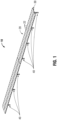
- the solar tracking system 10 includes a solar array 20, a support structure 30 that is configured to support the solar array 20, a base 40 that is configured to rotatably support the support structure 30, and an articulation system 100 ( FIG. 2 ) that is configured to articulate the solar array 20 and support structure 30 relative to the base 40.
- the solar array 20 includes a plurality of photovoltaic modules 22, each of which is mechanically and electrically coupled to one another, although it is contemplated that each photovoltaic module 22 may be mechanically and/or electrically insulated from one another.
- the photovoltaic modules 22 may be any suitable photovoltaic module capable of generating electrical energy from sunlight, such as monocrystalline silicon, polycrystalline silicon, thin-film, etc.
- the photovoltaic modules 22 define an upper surface 22a and an opposite, bottom surface 22b.
- the upper surface 22a of the photovoltaic modules 22 includes the photovoltaic cells (not shown) while the bottom surface 22b includes any suitable means for fixedly or selectively coupling the photovoltaic modules 22 to the support structure 30, such as mechanical fasteners (e.g., bolts, nuts, etc.), adhesives, welding, etc, although it is envisioned that the photovoltaic modules 22 may be bi-facial photovoltaic modules, in which case the bottom surface 22b may also include photovoltaic cells such that energy may be captured from both the upper and bottom surfaces 22a, 22b.
- the photovoltaic cells may be disposed within a suitable frame (not shown) which includes suitable means for fastening the photovoltaic modules 22 to the support structure 30.
- the frame may include fastening means on a bottom surface thereof (not shown), or clamps or other suitable fasteners (e.g., Z-brackets, C-clamps, angle brackets, etc.) may be utilized to abut a portion of the frame and selectively or fixedly couple the frame to the support structure 30.
- the support structure 30 includes a pair of parallel beams 32 ( FIG. 3 ) disposed in spaced relation to one another and extending along a length of the solar tracking system 10.
- the pair of parallel beams 32 may be any suitable beam capable of supporting the solar array 20, such as box beams, I-beams, H-beams, circular or round beams, etc.
- each beam of the pair of parallel beams 32 may include the same profile or may include different profiles, depending upon the installation needs of the solar tracking system 10.
- the support structure 30 includes pairs of transverse beams 34 defining opposed ends 34a and 34b ( FIG. 3 ).
- the pairs of transverse beams 34 are disposed parallel to one another and are spaced apart to receive a portion of the base 40, such that the support structure 30 may articulate without the base 40 interfering with articulation of the support structure 30 relative thereto, as will be described in further detail hereinbelow.
- the pair of transverse beams 34 may be any suitable beam capable of supporting the solar array 20, such as box beams, I-beams, H-beams, etc.
- each beam of the pairs of transverse beams 34 may include the same profile or may include different profiles, depending upon the installation needs of the solar tracking system 10.
- Each end of the opposed ends 34a, 34b of the pairs of transverse beams 34 is coupled to a respective beam of the pair of parallel beams 32.
- an end cap 36 is disposed adjacent to each end 34a or 34b of each beam of the pair of transverse beams 34.
- the end cap 36 defines a generally planar surface 36a extending between opposed side surfaces 36b and top and bottom surfaces 36c. Although generally illustrated as having rectangular outer profile, other suitable profiles are contemplated, such as square, hexagonal, circular, oval, etc.
- the planar surface 36a defines a bore 36d therethrough.
- the profile of the bore 36d may be any suitable profile, such as square, hexagonal, circular, oval, etc. and may be different than the profile of the planar surface 36a.
- the planar surface 36a defines a first pair of flanges 36e disposed adjacent the opposed side surfaces 36b and extending between the top and bottom surfaces 36c ( FIG. 6 ).
- the planar surface 36a defines a second pair of flanges 36f disposed adjacent the bore 36d and oriented parallel to the first pair of flanges 36e such that a channel 36g is defined between each of the first and second pairs of flanges 36e, 36f.
- the channels 36g are configured to receive a corresponding end 34a, 34b of each beam of the pair of transverse beams 34 such that the pair of transverse beams 34 may be coupled to the first and second pair of flanges 36e, 36f using any suitable means, such as mechanical fasteners, adhesives, welding, or the like.
- the cap 36 may have a distance between the top and bottom surfaces 36c that is the same as or less than the height of the pair of parallel beams 32.
- the cap 36 is fixedly or selectively coupled to each respective beam of the pair of parallel beams using any suitable means, such as mechanical fasteners, adhesives, welding, etc.
- the base 40 defines a generally C-shaped profile, although it is contemplated that the base may be any suitable beam capable of supporting the solar array 20 and the support structure 30, such as box beams, I-beams, H-beams, etc.
- the base 40 extends between a first end portion 40a configured to be anchored in the ground and an opposite, second end portion 40b configured to rotatably support the support structure 30.
- a pivot assembly 50 ( FIG. 6 ) is coupled to the second end portion 40a and includes a support 52, a pivot 54, a pivot pin 56, and a pair of brackets 58.
- the support 52 defines a generally C-shaped profile defining a planar portion 52a and a pair of opposed flanges 52b disposed on opposing end portions thereof.
- the pair of opposed flanges 52b is spaced apart such that the second end portion 40a of the base 40 is interposed therebetween and the planar portion 52a abuts the second end portion 40a, although it is contemplated that planar portion 52a of the support 52 may be spaced apart from the second end portion 40a of the base.
- the pair of opposed flanges 52b is fixedly or selectively coupled to the second end portion 40a using any suitable means, such as mechanical fasteners, adhesives, welding, etc.
- An actuator mounting flange 42 ( FIG.
- the actuator mounting flange 42 may be fixedly or selectively coupled to the base 40 using any suitable means, such as mechanical fasteners, adhesives, welding, etc. Although generally illustrated as defining a generally C-shaped profile, it is contemplated that the actuator mounting flange 42 may define any suitable profile, such as square, rectangular, etc. In this manner, the actuator mounting flange 42 defines a pair of opposed flanges 42a extending from a planar surface that is coupled to the outer surface of the base 40. In embodiments, the actuator mounting flange 42 may include a pair of independent flanges 42a that are individually coupled to the outer surface of the base 40.
- the pair of opposed flanges 42a defines a bore 42b therethrough that is configured to enable a pin (not shown) or other suitable means for rotatably coupling a portion of the articulation system 100 thereto when a portion of the articulation system 100 is interposed between the pair of opposed flanges 42a.
- the pivot 54 defines a generally C-shaped profile having a planar portion 54a and a pair of opposed flanges 54b extending therefrom.
- the pair of opposed flanges 54b may include any suitable profile such as square, rectangular, oval, etc.
- each flange of the pair of opposed flanges 54b may have the same profile or a different profile.
- the pair of opposed flanges 54b define a corresponding pair of through-holes 54c therethrough that are configured to receive the pivot pin 56 therein.
- the pivot pin 56 when the pivot pin 56 is received within the pair of opposed flanges 54b, the pivot pin 56 extends beyond each flange of the pair of opposed flanges 54b to engage a respective bracket of the pair of brackets 58.
- the pivot pin 56 defines a generally cylindrical profile extending between opposed end surfaces 56a. Each end surface of the opposed end surfaces 56a defines a relief (not shown) therein and extending toward one another. In this manner, the opposed end surfaces 56a define a generally D-shaped profile, although any suitable profile that is capable of inhibiting rotation of the pivot pin 56 relative to the pair of brackets 58 is contemplated, such as hexalobe, oval, square, rectangular, etc.
- the pair of brackets 58 defines a generally C-shaped profile having a planar portion 58a and a pair of opposed flanges 58b extending therefrom. Although generally illustrated as having a triangular profile, it is contemplated that the pair of opposed flanges 58b may include any suitable profile, such as square, rectangular, oval, etc. In embodiments, each flange of the pair of opposed flanges 58b may have the same profile or a different profile.
- the pair of opposed flanges defines a corresponding pair of through-bores (not shown) therethrough that are configured to fixedly receive the pivot pin 56 therein.
- each through-hole of the pair of through-holes defines a profile that is complementary to that of the profile of each corresponding end surface of the opposed end surfaces 56a of the pivot pin.
- the matching profiles of the through-holes and the opposed end surfaces 56a ensure that each bracket of the pair of brackets 58 remains aligned with one another to minimize or eliminate twisting of the support structure 30 (e.g., torque applied to one end surface is transferred through the pivot pin 56 to the opposite end surface of the opposed end surfaces 56a.
- the pivot pin 56 may not include a D-shaped profile an can be coupled to the pair of brackets 58 by friction fit, staking, adhesives, mechanical fasteners, welding, etc.
- the planar portion 58a is configured to be fixedly or selectively coupled to a corresponding beam of the pairs of transverse beams 34 to rotatably couple the support structure 30 to the base 40.
- the support structure 30 includes a pair of shear plates 38 having a generally L-shaped profile, although other suitable profiles are contemplated, such as C-shaped, etc.
- each shear plate 38 includes a generally planar portion 38a and a flange 38b disposed at an end portion thereof and extending perpendicular therefrom.
- the flange 38b is configured to abut an upper portion of a corresponding beam of the pairs of transverse beams 34.
- the planar portion 38a defines a hole 38c therethrough that is configured to receive a bearing or bushing of the articulation system 100, as will be described in further detail below.
- the pair of shear plates 38 is disposed in opposed relation to one another on a respective beam of the pairs of transverse beams 34.
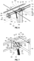
- the articulation system 100 includes an actuator 102 and a gearbox 120.
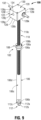
- the actuator 102 includes a tubular body 106, a nut 108, a power screw 110, and a heim joint assembly 112.
- the tubular body 106 of the actuator 102 extends between opposed end surfaces 106a and 106b.
- the tubular body 106 may include any suitable profile, such as square, rectangular, oval, hexagonal, etc.
- the opposed end surfaces 106a, 106b define a through-hole 106c therethrough that is configured to receive the nut 108 adjacent the end surface 106a and a heim joint assembly 112 adjacent the end surface 106b.
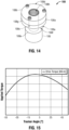
- the nut 108 ( FIG. 14 ) includes a washer 108a and a body portion 108b.
- the washer 108a defines a generally planar configuration having a generally circular profile corresponding to the profile of the tubular body 106.
- the washer 108a may include any suitable profile and may include the same or different profile than the tubular body 106.
- the washer 108a defines a through-hole 108c therethrough that is configured to receive a portion of the body portion 108b therethrough.
- the washer 108a is coupled to the end surface 106a of the tubular body 106 using any suitable means, such as mechanical fasteners, friction fit, adhesives, welding, etc.
- the body portion 108b of the nut 108 defines a generally cylindrical profile having an outer diameter generally the same as an outer diameter of the tubular body 106, although other suitable configurations are contemplated.
- the body portion 108b extends between opposed end surfaces 108d and 108e.
- the end surface 108e defines an annular relief 108f therein extending towards the end surface 108d and through an outer surface 108g of the nut 108.
- the annular relief 108f terminates in a face 108g oriented opposite to the end surface 108d and is configured to abut a portion of the washer 108a.
- the body portion 108b of the nut 108 may be selectively coupled to the washer 108a using any suitable means, and in embodiments, may be fixedly coupled to the washer 108a using any suitable means, such as adhesives, friction fit, welding, etc.
- the opposed end surfaces 108d, 108e of the body portion 108b define a threaded bore 108h therethrough that is configured to threadably engage the power screw 110, such that the power screw 110 can translate therewithin when rotated in a first or second direction relative to the nut 108, as will be described in further detail hereinbelow.
- the heim joint assembly 112 includes a heim joint washer 112a, a heim joint 112b, and a heim joint nut 112c.
- the heim joint washer 112a extends between opposed end surfaces 112e and 112f and defines a generally cylindrical profile that is complimentary to the profile of the tubular body 106, although it is contemplated that the profile of the heim joint washer 112a may include any suitable profile, such as square, rectangular, oval, etc.
- the end surface 112e is configured to abut end surface 106b of the tubular body and may be selectively or fixedly coupled thereto using any suitable means, such as mechanical fasteners, friction fit, adhesives, welding, etc.
- the opposed end surfaces 112e, 112f define a threaded bore 112g therethrough that is configured to threadably engage a portion of the heim joint 112b.
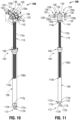
- the heim joint 112b may be any suitable articulating joint and includes an articulating head portion 112h and a threaded shank 112i ( FIG. 11 ) extending therefrom.
- the threaded shank 112i is configured to threadably engage the threaded bore 112g of the heim joint washer 112a such that the heim joint 112b may translate within the heim joint washer 112a when the heim joint 112b is rotated.
- the overall length of the actuator 102 can be increased or decreased by rotating the heim joint 112b in a first direction or second, opposite direction.
- the head portion 112h of the heim joint 112b defines a lumen 112j therethrough that is configured to receive a suitable fastener (e.g., bolt, pin, etc.) therein to rotatably couple the heim joint 112b, and thereby the actuator 102, to the actuator mounting flange 42 ( FIG. 2 ) of the base 40.
- a suitable fastener e.g., bolt, pin, etc.
- the heim joint nut 112c is threadably coupled to the threaded shank 112i of the heim joint 112b.
- the heim joint nut 112c is configured to act as a jam nut such that when the heim joint nut 112c is threaded in a first direction, the heim joint nut 112c abuts the end surface 112f of the heim joint washer 112a, and further rotation of the heim joint nut 112c in the first direction tightens the heim joint nut 112c against the end surface 112f of the heim joint washer 112a to lock the position of the heim joint 112b relative to the heim joint washer 112a. To loosen the heim joint nut 112c, the heim joint nut 112c is rotated in a second, opposite direction.
- the heim joint 112b may be any suitable articulating joint, and may be integrally formed with the actuator tube 106 or the heim joint washer 112a.
- the heim joint 112b may be a ball bearing (stainless steel, bronze, brass, polymer, etc.) or a bushing (brass, bronze, polymer, etc.).
- the articulation system 100 may not utilize a heim joint assembly 112. Rather, an outer surface 106d of the tubular body 106 defines a transverse bore (not shown) that is configured to receive a suitable fastener (e.g., bolt, pin, etc.) therein to rotatably couple the tubular body 106, and thereby the actuator 102, to the actuator mounting flange 42 of the base 40.
- a suitable fastener e.g., bolt, pin, etc.
- the power screw 110 extends between a first end surface 110a and an opposite, second end surface 110b and defines a threaded outer surface 110c therebetween.
- the threaded outer surface 110c includes a threadform that is complimentary to that of the nut 108 such that the power screw 110 may threadably engage the threaded bore 108h of the nut 108.
- the overall length of the actuator 102 increases and as the power screw 110 is rotated in a second, opposite direction, the overall length of the actuator 102 decreases.
- the increase or decrease in the overall length of the actuator 102 causes articulation of the support structure 30 and solar array 20 about the pivot pin 56 of the pivot assembly 50 ( FIG. 6 ).
- the threaded outer surface 110c of the power screw 110 may define any suitable threadform (e.g., square, trapezoidal, buttress, etc.) capable of supporting and transmitting large loads, although other threadforms are also contemplated, such as triangular threadforms (e.g., uniform thread standard, etc.).
- the power screw 110 may be a ball screw, a glidescrew, a leadscrew, etc.
- the threaded outer surface 110c of the power screw 110 defines a trapezoidal threadform such as an acme threadform and has self-locking or anti-backdrive properties sufficient to inhibit the power screw 110 from rotating under the static weight of the solar array 20, support structure 30, and various components of the articulation system 100 that are supported by the power screw 110. Additionally, the anti-backdrive properties of the power screw 110 inhibit the power screw from rotating when an external force is applied to the solar tracking system 10, such as wind, snow, wildlife, etc.
- the first end surface 110a is configured to couple to a portion of the gearbox 120 such that a rotational force imparted on the gearbox 120 is transmitted to the power screw 110, as will be described in further detail hereinbelow.
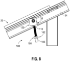
- the gearbox 120 includes an outer casing 122 and a gear train 126.
- the outer casing 122 ( FIG. 9 ) defines a body 128 and a cover 130.
- the body 128 defines a generally square profile extending between opposed end surfaces 128a and 128b.
- the end surface 128a defines a cavity 128c therein terminating at an inner surface 128d.
- the inner surface 128d and the opposed end surface 128b define a through-bore 128e therethrough that is configured to receive a portion of the power screw 110 therein.
- the through-bore 128e is dimensioned to permit articulation of the power screw 110 relative to the body 122 without causing interference (e.g., the power screw 110 is permitted to pivot relative to the body 122).
- the body 128 defines a first pair of opposed side surfaces 128k and 128f and a second pair of opposed side surfaces 128g and 128h disposed transverse to the first pair of opposed side surfaces 128k, 128f.
- Each of the side surfaces of the first pair of opposed side surfaces 128k, 128f define a through-hole 128i therethrough that is configured to rotatably support a portion of an input shaft 132 therethrough and each of the side surfaces of the second pair of opposed side surfaces 128g, 128h defines a bore 128j ( FIG. 9 ) therethrough that is configured to support a portion of an idler shaft 134 therein, as will be described in further detail hereinbelow.
- the cover 130 is configured to selectively couple to the end surface 128a using any suitable means, such as mechanical fasteners, adhesives, friction fit, etc.
- the gear train 126 includes an input shaft 132, an idler shaft 134, a pair of support bushings 136, a drive gear 138, an idler gear 140, a driven gear 142, and a yoke 144.
- the input shaft 132 defines a generally cylindrical profile extending between a first end portion 132a and an opposite second end portion 132b.
- An outer surface 132c of the input shaft 132 defines a hole 132d adjacent each of the first and second end portions 132a, 134b that is configured to selectively receive a pin (not shown) or other suitable device capable of rotatably supporting and longitudinally fixing a drive shaft 150 ( FIG. 7 ) of the solar tracking system 10, as will be described in further detail hereinbelow.
- the input shaft 132 is configured to be rotatably supported within the through-hole 128i of the first pair of opposed side surfaces 128e, 128f using any suitable means, such as a bushing, bearing, etc.
- the idler shaft 134 defines a generally cylindrical profile extending between opposed end portions 134a and 134b.
- An outer surface 134c of the idler shaft defines a transverse bore 134d therethrough at a center portion thereof (e.g., approximately the middle of the idler shaft 134).
- the transverse bore 134d extends through the idler shaft 134 perpendicular to an axis A-A defined through the length (e.g., through the opposed end portions 134a, 134b) of the idler shaft 134 and is configured to receive a portion of the input shaft 132 therein.
- the transverse bore 134d is dimensioned such that the input shaft 132 may rotate about the axis A-A approximately 10 degrees in either direction (e.g., ⁇ 10°) without the input shaft 132 impacting any portion of the transverse bore 134d (e.g., the transverse bore 134d includes an inner dimension that is larger than an outer dimension of the input shaft 132), as will be described in further detail hereinbelow.
- the pair of support bushings 136 defines a generally cylindrical profile extending between a first end surface 136a and a second, opposite end surface 136b. Each bushing of the pair of support bushings 136 is substantially similar, and therefore, only one support bushing 136 will be described in detail herein in the interest of brevity.
- the first end surface 136a defines an annular relief 136c extending through an outer surface of the support bushing 136 and extending towards the second end surface 136b.
- the annular relief 136c terminates at an annular face 136d having an outer dimension that is greater than the outer dimension of the annular relief.
- the second end surface 136b defines a first counterbore 136e therein extending towards the first end surface 136a and terminating at an annular face 136f.
- the annular face 136f of the first counterbore 136e defines a boss 136g extending therefrom and protruding past the second end surface 136b and terminating at a third end surface 136h.
- An outer surface of the boss 136g is configured to be received within the through-hole 128i of the outer casing 122 such that the outer casing 122 is rotatably supported thereon.
- the third end surface 136h and the first end surface 136a of the support bushing 136 define a through-bore (not shown) therethrough that is configured to rotatably support a portion of the input shaft 132 therein.
- the first end surface 136a defines a second counterbore 136j therein.
- the support bushing 136 may be formed from more than one component and in one non-limiting embodiment, may be a bearing with a bushing, a bearing with an extended inner race (e.g., roller bearing, ball bearing, etc.), etc.
- the annular face 136d of the support bushing 136 is configured to abut a portion of a respective shear plate 38 of the support structure 30 to inhibit the support bushing 136 from entirely passing through a hole 38c of the shear plate 38. In this manner, the annular face 136d locates the support bushing 136 relative to the gearbox 134.
- the yoke 144 defines a generally U-shaped profile having a planar surface 146 and opposed tabs 148 extending therefrom ( FIG. 7 ). Although generally illustrated as having a triangular profile, it is contemplated that the opposed tabs 148 may include any suitable profile, and each tab may be the same or include different profiles.
- the planar surface 146 defines a bore (not shown) therethrough configured to receive a portion of the power screw 110 therein. It is contemplated that the bore may include a suitable bearing, bushing, etc. (not shown) or in embodiments, may not include a bearing or bushing but rather at least one thrust bearing or bushing (not shown) may be disposed adjacent the planar surface 146 and concentric to the bore.
- the opposed tabs 148 define a through-hole (not shown) therethrough that is configured to support a portion of the idler shaft 134 therein.
- the through-hole is dimensioned to fixedly retain the idler shaft 134 therein, such that the idler shaft 134 is inhibited from rotating about the axis A-A, although it is contemplated that the idler shaft 134 may freely rotate within the through-hole of the opposed tabs 148.
- the idler shaft 134 is fixedly retained within the through-hole, it is contemplated that the idler shaft 134 maybe fixedly retained using any suitable means, such as friction fit, keys, splines, adhesives, etc.
- Each of the opposed tabs 148 defines a boss 148a thereon that is concentric with the through-hole.
- Each boss of pair of bosses 148a is configured to be received within a respective the bore 128j of the outer casing 122 of gearbox 128 such that each bore 128j rotatably supports each respective boss 148a to enable the yoke 144 to rotate about an axis defined by the idler shaft 134.
- the drive gear 138 is supported on the input shaft 132 and is coupled thereto using any suitable means, such as a clamp, friction fit, pins, etc., such that rotation of the input shaft 132 causes a corresponding rotation of the drive gear 138.
- any suitable means such as a clamp, friction fit, pins, etc.
- the drive gear 138 may be any suitable device capable of transmitting rotational motion from the input shaft 132 to the idler gear 140, and in one non-limiting embodiment, the drive gear 138 may be a face-gear or the like.
- the idler gear 140 is rotatably supported on the idler shaft 134 such that the idler gear 140 is free to rotate relative to the idler shaft 134 using any suitable means, such as a bushing, bearing, etc.
- the idler gear 140 is sized and dimensioned such that a portion of the idler gear 140 is able to mesh with the drive gear 138 and a portion of the idler gear 140 is able to mesh with the driven gear 142.
- the idler gear 140 may be any suitable device capable of transmitting rotational motion from the drive gear 138 to the driven gear 142.
- the driven gear 142 is fixedly retained on a portion of the power screw 110 adjacent the first end surface 110a thereof using any suitable means, such as a clamp, friction fit, pins, etc., such that rotation of the driven gear 142 causes a corresponding rotation of the power screw 110.
- any suitable means such as a clamp, friction fit, pins, etc.
- the driven gear 142 may be any suitable device capable of transmitting rotational motion from the idler gear 140 to the power screw 110.
- the driven gear 142 clamps the power screw 110 to the yoke 144 such that the power screw 110, and thus the driven gear 142, is inhibited from translating relative to the yoke 144.
- each of the drive gear 138, the idler gear 140, the driven gear 142, the pair of support bushings 136, and idler shaft 134 may be translatably fixed using circlips, e-clips, pins, adhesives, welding, etc. In this manner, the relative location of each of the drive gear 138, idler gear 140, driven gear, the pair of support bushings 136, and idler shaft 134 may be fixed relative to one another to ensure proper engagement of each of the drive gear 138, the idler gear 140, and the driven gear 142 during operation of the articulation system 100.
- any of the drive gear 138, idler gear 140, and driven gear 142 may be a face gear or the like.
- the gearbox 120 may not include a yoke 144, and rather the idler shaft 134 may be supported by the body 128 of the gearbox 120. In this manner, the body 128 of the gearbox supports the upper portion of the power screw 110, and the driven gear 142 clamps the power screw 110 to the body 128.
- the solar tracking system 10 includes an articulation system 100 disposed at each base 40, although it is contemplated that the solar tracking system 10 may include only one articulation system 100, an articulation system 100 may be disposed at every other base 40, or any other suitable pattern depending upon the installation needs of the solar tracking system 10.
- the placement of an articulation system 100 at each base 40 reduces the load each articulation system 100 is required to support. As a consequence, the overall size of the components of the articulation system 100 can be reduced, thereby saving materials and cost.
- using multiple articulation systems 100 increases the overall stiffness of the solar tracking system 10 by reducing the distance between each point at which an articulation system 100 is placed, thereby reducing the torsional loading on the support structure 30, amongst other benefits. Further, using multiple actuation systems 100 reduces the need for the pivot pin 56 of the support structure 30 to be placed at the center of gravity of the support structure 30 and solar array 20 assemblies.
- placement of the pivot pin 56 at the geometric center of rotation of the solar array 20 and support structure 30 assembly may cause an unbalanced load as the support structure 30 is articulated by the actuation assemblies 100.
- the amount of drive torque required to rotate the support structure 30 about the pivot pin 56 is relatively low.
- the torque required to rotate the support structure 30 increases until the support structure 30 is placed in an approximately horizontal orientation. Continued rotation of the support structure 30 towards the west requires a diminishing amount of torque as the center of gravity of the solar array 20 and support structure 30 assembly migrates closer to the geometric center of rotation.
- the pivot pin 56 may be disposed at the center of mass of the solar array 20 and support structure 30 assembly rather than the geometric center of rotation. In this manner, the mass of the solar array 20 and support structure 30 is balanced about the pivot pin 56 and the torque required to articulate the support structure 30 about the pivot pin 56 remains substantially consistent, with little to no variation in the torque required to articulate the support structure through its range of motion. As such, the amount of energy required to articulate the support structure 30 is reduced and the various components required to support the solar array 20 may be substantially similar (e.g., no need to design certain components to take a larger load than others), thereby reducing design time and reducing the number of differing components in the solar tracking assembly 10.
- each solar array 20 may include a differing amount of wiring, actuatotion systems 100, drive shafts 150, etc. which necessarily means that each solar array 20 may include a different weight than one another.
- each solar array may include a different axis of rotation, which in turn, reduces unbalanced loads placed upon the articulation system 100.
- a plurality of drive shafts 150 are disposed on the support structure 30 and coupled to a respective input shaft 132 of a respective gearbox 120.
- each base 40 may remain identical, thereby reducing the number of variations of the base 40 required to construct the solar tracking system 10. It is contemplated that each of the plurality of drive shafts 150 may be rotatably supported by a bracket 152 ( FIG.
- the outer dimension of the drive shaft 150 and the number of brackets 152 may vary depending on the installation needs of the solar tracking system 10. As can be appreciated, the larger the outer dimension of the drive shaft 150 and a greater number of brackets 152 increases the torsional load capacity of the drive shaft 150 while minimizing wind-up or twist in the drive shaft and reducing the proclivity of the drive shaft 150 to buckle under torsional load.
- the bracket 152 inhibits buckling of the drive shaft 150 over its length, and therefore, enables a reduction in the overall diameter and wall thickness of the drive shaft 150 required to transfer a particular load without wind-up or buckling. In this manner, it is contemplated that one or more brackets 152 may be utilized. In one non-limiting embodiment, two brackets 152 are utilized to support the drive shaft 150 at intervals of one third of the overall length of the drive shaft 150.
- each solar array 20 may increase or decrease due to thermal expansion or contraction of the various components thereof.
- the location at which the gearbox 120 secures to the driveshaft 150 may vary due to the dimensional changes driven by thermal expansion or contraction of the driveshaft and/or support structure 30.
- the yoke 144 is rotatably supported within the outer casing 122 of the gearbox 120 about the longitudinal axis A-A. As such, as the support structure 30 expands and contracts and the gearbox 120 is caused to translate transverse to the actuator mounting flange 42 of the base 40, the actuator 102, via the heim joint 112b, is permitted to rotate about the fastener coupling the heim joint 112b to the mounting flange 42.
- the transverse bore 134d of the idler shaft 134 provides clearance for the input shaft 132 to pass therethrough without interference as the yoke 144, and therefore the idler shaft 134, rotates about the axis A-A. Further, the support bushings 38 inhibit the outer casing 122 of the gearbox 120 from rotating relative to the driveshaft 150 to inhibit binding or misalignment between the input shaft 132 of the gearbox 120 and the driveshaft 150.
- the articulation system 100 includes a motor 160 and an associated motor gear box 162.
- the motor 160 may be any suitable motor capable of transmitting rotational motion to the drive shaft 150, such as an alternating current (AC) motor, a direct current (DC) motor, a servo, a stepper motor, etc.
- the motor 160 is a brushless direct current (DC) motor.
- the motor 160 is coupled to the gear box 162 using any suitable means, such as mechanical fasteners, adhesives, welding, etc.
- the gear box 162 is coupled to the support structure 30 using any suitable means, such as mechanical fasteners, adhesives, welding, etc.
- the gear box 162 may be any suitable gearbox capable of transmitting rotational motion from the motor 160 to the drive shaft 150, such as a constant mesh gear box, belts and pulleys, sprockets and chains, friction wheels, hydraulic, etc.
- each articulation system 100 may include a respective motor 160 and gear box 162, or in embodiments, only one motor 160 and gearbox 162 may be utilized.
- a motor 160 and/or gearbox 162 may be placed at any base 40 (regardless of the presence of an articulation system 100) and the rotational torque supplied by the motor 160 will be transferred to each articulation system 100 via the plurality of drive shafts 150.
- the motor 160 and gearbox 162 may be placed at an outer-most base 40.
- the motor 160 may be placed at any base 40 and may directly drive the plurality of drive shafts 150 without the use of the gearbox 162.
- utilizing multiple motors 160 reduces the size of the motor required to produce the appropriate amount of torque to articulate the support structure 30.
- utilizing a gear box 162 reduces the size of the motor 160 required to produce the appropriate amount of torque to articulate the support structure 30.
- utilizing multiple motors 160 enables smaller and lighter drive shafts 150 to be utilized and reduces the number of brackets 152 that are required to inhibit buckling of the drive shafts 150, and in embodiments, may eliminate the need for the drive shafts 150 altogether.
- each actuation system 100 may include a positive stop (not shown) or other similar device capable of inhibiting over extension thereof and to limit any damaged caused therefrom.
- the positive stop for each individual actuation system 100 may be calibrated to inhibit actuation of any one actuation system 100 relative to one another to a certain degree to minimize torsional loads and/or misalignment between adjacent solar arrays 20.
- each actuation system 100 is calibrated to ensure that the position of each actuator 102 of the solar tracking system 10 is substantially the same. Placing each actuator 102 in the substantially same position reduces the amount of twist of the solar array 20.
- each actuation assembly 100 may include a positive stop to ensure the actuator 102 does not over extend and damage components of the solar tracking system 10.
- a signal is transmitted from a suitable controller to the motor or motors 160 to rotate the power screw 110.
- the sun is traveling in an east to west direction (e.g., daylight into twilight)
- the signal causes the motor 160 to rotate in a first direction, thereby causing the power screw 110 to rotate in a corresponding first direction to increase the overall length of the actuator 102.
- Increasing the length of the actuator 102 causes the support structure 30 to rotate clockwise about the pivot pin 56 and cause the solar array 20 to rotate in a corresponding clockwise direction.
- the signal causes the motor 160 to rotate in a second direction, opposite to the first direction, thereby causes the power screw 110 to rotate in a corresponding second direction that is opposite to the first direction to decrease the overall length of the actuator 102.
Landscapes
- Engineering & Computer Science (AREA)
- General Engineering & Computer Science (AREA)
- Mechanical Engineering (AREA)
- Sustainable Development (AREA)
- Life Sciences & Earth Sciences (AREA)
- Sustainable Energy (AREA)
- Physics & Mathematics (AREA)
- Thermal Sciences (AREA)
- Chemical & Material Sciences (AREA)
- Combustion & Propulsion (AREA)
- Photovoltaic Devices (AREA)
- Transmission Devices (AREA)
- Radiation-Therapy Devices (AREA)
- Switches Operated By Changes In Physical Conditions (AREA)
Claims (15)
- Ein Solartracker (10), aufweisend:eine Mehrzahl von Basen (40);eine Tragstruktur (30), aufweisend mindestens einen Längsträger (32), der sich entlang einer Länge des Solartrackers (10) erstreckt, und eine Mehrzahl von Querträgerpaaren (34), die im Wesentlichen orthogonal zu dem mindestens einen Längsträger (32) orientiert sind und wobei jedes Querträgerpaar (34) drehbar mit einer der Mehrzahl von Basen (40) gekoppelt ist, sodass eine Drehung der Querträgerpaare (34) die Tragstruktur (30) relativ zu der Mehrzahl von Basen (40) dreht;eine Mehrzahl von Getriebeboxen (120), wobei jede Getriebebox (120) von mindestens einem der Mehrzahl von Querträgerpaaren (34) getragen wird;eine Antriebswelle (150), die entlang einer Länge der Tragstruktur (30) parallel zu dem mindestens einen Längsträger (32) verläuft und mit jeder der Mehrzahl von Getriebeboxen (120) gekoppelt ist; undfür jede Getriebebox (120) einen Aktuator (102), der an einem Ende über die Getriebebox (120) mit der Antriebswelle (150) mechanisch gekoppelt ist und an einem zweiten Ende mit einer der Mehrzahl von Basen (40) gekoppelt ist, wobei der Aktuator (102) eine Antriebsschraube (110) aufweist, die, wenn sie von der Antriebswelle (150) angetrieben wird, aus einem Körper (106) ausfährt oder sich in diesen zurückzieht, wodurch die Tragstruktur (30) veranlasst wird, sich um eine Drehachse zu drehen,dadurch gekennzeichnet, dass für jede Getriebebox (120) sich eine Eingangswelle (132) durch die Getriebebox (120) erstreckt, wobei die Eingangswelle (132) mechanisch mit einem Abschnitt der Antriebswelle (150) gekoppelt ist, und sich ein Abschnitt der Eingangswelle (132) durch das mindestens eine der Mehrzahl von Querträgerpaaren (34) erstreckt, welches die Getriebebox (120) trägt.
- Der Solartracker (10) nach Anspruch 1 ferner aufweisend einen Motor (160), der mit der Antriebswelle (150) gekoppelt ist, und vorzugsweise an der Tragstruktur (30) getragen ist.
- Der Solartracker (10) nach Anspruch 2, wobei die Drehachse versetzt zu einer Mittellinie der Tragstruktur (30) angeordnet ist, vorzugsweise wobei die Drehachse ein Massenschwerpunkt der Tragstruktur (30) ist.
- Der Solartracker (10) nach Anspruch 1, ferner aufweisendein Antriebsrad (138) in jeder Getriebebox (120), das mit der Antriebswelle (150) trieblich verbunden ist, undein Zwischenrad (140) in jeder Getriebebox (120), das trieblich mit dem Antriebsrad (138) verbunden ist, undeine Leerlaufwelle (134), um die sich das Zwischenrad (140) dreht, undeine in der Leerlaufwelle (134) ausgebildete Bohrung (128j), durch die eine Eingangswelle (132) hindurchgeführt ist.
- Der Solartracker (10) nach Anspruch 4, wobei die Eingangswelle (132) an beiden Enden der Getriebebox (120) mechanisch an die Antriebswelle (150) gekoppelt ist.
- Der Solartracker (10) nach Anspruch 4 ferner aufweisend ein angetriebenes Rad (142), das mit dem Leerlaufrad (140) und der Antriebsschraube (110) trieblich verbunden ist.
- Der Solartracker (10) nach Anspruch 6, ferner aufweisend ein Joch (144), das mit der Antriebsschraube (110) trieblich verbunden ist und die Leerlaufwelle (134) trägt, wobei das Joch (144) die von der Antriebsschraube (110) ausgeübte Kraft aufnimmt und die Kraft auf eines der Mehrzahl von Querträgerpaaren (34) überträgt.
- Der Solartracker (10) nach Anspruch 7 ferner aufweisend eine Mehrzahl von Scherplattenpaaren (38), wobei jede Getriebebox (120) durch ein Paar Scherplatten (38) der Mehrzahl von Scherplattenpaaren (38) mit einem der Mehrzahl von Querträgerpaaren (34) trieblich verbunden ist.
- Der Solartracker (10) nach Anspruch 4, wobei das Antriebsrad (138), das Zwischenrad (140) und das angetriebene Rad (142) jeweils Stirnräder sind.
- Der Solartracker (10) nach Anspruch 1 ferner aufweisend eine Mehrzahl von Scherplattenpaaren (38), wobei jede Getriebebox (120) durch ein Scherplattenpaar (38) der Mehrzahl von Scherplattenpaaren (38) mit einem der Mehrzahl von Querträgerpaaren (34) trieblich verbunden ist.
- Der Solartracker (10) nach Anspruch 10 ferner aufweisend ein Paar von Buchsen (136) auf entgegengesetzten Seiten jeder Getriebebox (120), wobei das Paar von Buchsen (136) eine Eingangswelle (132) trägt, die sich durch die Getriebebox (120) erstreckt, wobei die Eingangswelle (132) mit der Antriebswelle (150) trieblich verbunden ist.
- Der Solartracker (10) nach Anspruch 1, wobei die Getriebebox (120) eine Mehrzahl von Stirnrädern umfasst.
- Der Solartracker (10) nach Anspruch 1 ferner aufweisend eine Mehrzahl von Schwenkstiften (56), die die Drehachse definieren.
- Der Solartracker (10) nach Anspruch 13 ferner aufweisend eine Mehrzahl von Drehlagern (54), durch die jeweils einer der Mehrzahl von Schwenkstiften (56) verläuft, wobei jedes der Mehrzahl von Drehlagern (54) mechanisch mit einer Basis (40) verbunden ist.
- Der Solartracker (10) nach Anspruch 14 ferner aufweisend eine Mehrzahl von Halterungspaaren (152), wobei eine einzelne Halterung (152) jedes der Mehrzahl von Halterungspaaren (152) mechanisch mit einem jeweiligen Träger eines Querträgerpaars (34) verbunden und konfiguriert ist, einen jeweiligen Schwenkstift (56) der Mehrzahl von Schwenkstiften (56) aufzunehmen, um eine Drehung der Tragstruktur (30) um die Drehachse zu ermöglichen.
Priority Applications (1)
| Application Number | Priority Date | Filing Date | Title |
|---|---|---|---|
| EP23197651.5A EP4270780A3 (de) | 2018-03-23 | 2019-03-22 | Mehrfachaktuatorsystem für sonnenfolger |
Applications Claiming Priority (3)
| Application Number | Priority Date | Filing Date | Title |
|---|---|---|---|
| US15/933,717 US11283395B2 (en) | 2018-03-23 | 2018-03-23 | Multiple actuator system for solar tracker |
| US16/124,773 US11159120B2 (en) | 2018-03-23 | 2018-09-07 | Multiple actuator system for solar tracker |
| PCT/US2019/023617 WO2019183492A1 (en) | 2018-03-23 | 2019-03-22 | Multiple actuator system for solar tracker |
Related Child Applications (2)
| Application Number | Title | Priority Date | Filing Date |
|---|---|---|---|
| EP23197651.5A Division-Into EP4270780A3 (de) | 2018-03-23 | 2019-03-22 | Mehrfachaktuatorsystem für sonnenfolger |
| EP23197651.5A Division EP4270780A3 (de) | 2018-03-23 | 2019-03-22 | Mehrfachaktuatorsystem für sonnenfolger |
Publications (4)
| Publication Number | Publication Date |
|---|---|
| EP3769412A1 EP3769412A1 (de) | 2021-01-27 |
| EP3769412A4 EP3769412A4 (de) | 2021-12-22 |
| EP3769412B1 true EP3769412B1 (de) | 2023-10-25 |
| EP3769412C0 EP3769412C0 (de) | 2023-10-25 |
Family
ID=67983798
Family Applications (2)
| Application Number | Title | Priority Date | Filing Date |
|---|---|---|---|
| EP23197651.5A Pending EP4270780A3 (de) | 2018-03-23 | 2019-03-22 | Mehrfachaktuatorsystem für sonnenfolger |
| EP19771605.3A Active EP3769412B1 (de) | 2018-03-23 | 2019-03-22 | Multiaktuatorsystem für sonnenfolger |
Family Applications Before (1)
| Application Number | Title | Priority Date | Filing Date |
|---|---|---|---|
| EP23197651.5A Pending EP4270780A3 (de) | 2018-03-23 | 2019-03-22 | Mehrfachaktuatorsystem für sonnenfolger |
Country Status (7)
| Country | Link |
|---|---|
| US (5) | US11283395B2 (de) |
| EP (2) | EP4270780A3 (de) |
| CN (2) | CN118611558A (de) |
| AU (3) | AU2019239320B2 (de) |
| ES (1) | ES2964176T3 (de) |
| PL (1) | PL3769412T3 (de) |
| WO (1) | WO2019183492A1 (de) |
Families Citing this family (29)
| Publication number | Priority date | Publication date | Assignee | Title |
|---|---|---|---|---|
| DE102018117228A1 (de) * | 2017-07-18 | 2019-01-24 | Magna Closures Inc. | Solarpaneelträger und Antriebssystem |
| JP1624247S (de) * | 2018-03-22 | 2019-02-12 | ||
| JP1623600S (de) * | 2018-04-04 | 2019-02-04 | ||
| IT201900020216A1 (it) * | 2019-10-31 | 2021-05-01 | Francesco Pierobon | Impianto fotovoltaico, in particolare un impianto fotovoltaico a terra |
| ES1249610Y (es) * | 2020-05-05 | 2020-10-13 | Niasa Neff Y Asoc S A | Seguidor solar |
| US11108353B1 (en) | 2020-07-14 | 2021-08-31 | FTC Solar, Inc. | Systems and methods for array level terrain based backtracking |
| US11139775B1 (en) | 2020-07-14 | 2021-10-05 | FTC Solar, Inc. | Systems and methods for terrain based backtracking for solar trackers |
| US11955924B2 (en) | 2020-07-27 | 2024-04-09 | Kloeckner Metals Corporation | Solar tracking mounting system |
| WO2022040181A1 (en) * | 2020-08-17 | 2022-02-24 | Nextracker Inc. | Variable radius under module bearing |
| US11522491B2 (en) | 2020-08-26 | 2022-12-06 | FTC Solar, Inc. | Systems and methods for adaptive range of motion for solar trackers |
| US11984841B2 (en) * | 2020-09-08 | 2024-05-14 | Nextracker Llc | Distributed locking tracker |
| EP4414628B1 (de) | 2020-09-14 | 2025-11-05 | Nextracker Inc. | Pier für ein solarnachführer |
| US10935992B1 (en) | 2020-09-16 | 2021-03-02 | FTC Solar, Inc. | Systems and methods for solar trackers with diffuse light tracking |
| US20220107117A1 (en) * | 2020-10-05 | 2022-04-07 | Nextracker Inc. | D-shaped torque tube and bearing assemblies |
| WO2022121536A1 (zh) * | 2020-12-08 | 2022-06-16 | 杭州中德传动设备有限公司 | 一种太阳能跟踪器 |
| GB2606032B (en) * | 2021-04-23 | 2025-04-02 | Nagonic Design Ltd | A moveable solar panel support apparatus |
| US11817816B2 (en) * | 2021-08-09 | 2023-11-14 | Solargik Ltd | Solar energy system and geared drive system |
| CA3238248A1 (en) * | 2021-11-30 | 2023-06-08 | Chen Li | Systems and methods for tracker-level protection |
| WO2023114981A2 (en) | 2021-12-16 | 2023-06-22 | FTC Solar, Inc. | Solar tracker system including a frame assembly |
| CN114189201A (zh) * | 2021-12-20 | 2022-03-15 | 清源科技(厦门)股份有限公司 | 一种光伏支架 |
| TR2022000204A2 (tr) * | 2022-01-07 | 2022-02-21 | Yunus Emre Yasar | Güneş taki̇p si̇stemi̇ |
| ES1293486Y (es) * | 2022-06-21 | 2022-10-24 | Trina Solar S L U | Rodamiento para sujecion de ejes de giro sobre pilares de sustentacion |
| CN217736234U (zh) * | 2022-08-16 | 2022-11-04 | 常州中信博新能源科技有限公司 | 一种平行驱动装置 |
| US11848638B1 (en) * | 2022-08-27 | 2023-12-19 | Sunmodo Corporation | Device and system for mounting solar panels to metal roofs |
| EP4343226A1 (de) * | 2022-09-23 | 2024-03-27 | Thomas Bockmeyer | Solarpaneel und zaun, ausgestattet mit mindestens einem derartigen solarpaneel |
| EP4391364B1 (de) | 2022-12-21 | 2025-07-16 | P4Q Electronics, S.L. | Sonnenfolger und steuerungsverfahren des sonnenfolgers |
| CN116073750A (zh) * | 2023-03-06 | 2023-05-05 | 江苏瑞智中和新能源科技有限公司 | 一种光伏支架 |
| US12231078B1 (en) * | 2023-08-02 | 2025-02-18 | Nextracker Llc | Solar module mounting assemblies |
| WO2025050053A1 (en) * | 2023-08-31 | 2025-03-06 | Dinino Jones Emily | Systems and methods for protective shading structures |
Family Cites Families (402)
| Publication number | Priority date | Publication date | Assignee | Title |
|---|---|---|---|---|
| US600638A (en) | 1898-03-15 | Post-winder | ||
| US576478A (en) | 1897-02-02 | Thirds to william f | ||
| US613243A (en) | 1898-11-01 | Walter james carroll and john | ||
| US496249A (en) | 1893-04-25 | Otis l | ||
| US560606A (en) | 1896-05-19 | James a | ||
| US601491A (en) | 1898-03-29 | Tenbaugh | ||
| US586737A (en) | 1897-07-20 | Harrow for race-courses | ||
| US647843A (en) | 1899-08-04 | 1900-04-17 | Warren T Kellogg | Sash-pulley. |
| US655210A (en) | 1900-03-22 | 1900-08-07 | Charles I Dupont | Elliptic spring. |
| US687839A (en) | 1901-02-27 | 1901-12-03 | Nellie S Kerr | Hip-form girdle. |
| US688620A (en) | 1901-06-13 | 1901-12-10 | Dora Floerckey | Hook and eye. |
| US697022A (en) | 1901-09-14 | 1902-04-08 | Timothy J Sammons | Car-coupling. |
| US808066A (en) | 1902-10-24 | 1905-12-26 | Wilhelm Borchers | Process for the production of metallic calcium. |
| US815303A (en) | 1903-08-25 | 1906-03-13 | John A Woods | Recording apparatus for motor-vehicles. |
| US792342A (en) | 1905-01-11 | 1905-06-13 | Charles H Nesselroad | Building-block and chimney. |
| US800537A (en) | 1905-01-18 | 1905-09-26 | Anatole Benoit | Cigarette-making machine. |
| US803040A (en) | 1905-04-21 | 1905-10-31 | Lynch D West | Quilting-frame. |
| US801914A (en) | 1905-04-27 | 1905-10-17 | Benjamin H Rhoads | Dial-train for timepieces. |
| US801781A (en) | 1905-04-27 | 1905-10-10 | William Baxter Glisson | Chart. |
| US815308A (en) | 1905-10-05 | 1906-03-13 | William H Perry | Rotary fender and cleaner for surface railways. |
| US4063543A (en) | 1976-08-12 | 1977-12-20 | John Henry Hedger | Servo tracking apparatus |
| US4172443A (en) | 1978-05-31 | 1979-10-30 | Sommer Warren T | Central receiver solar collector using analog coupling mirror control |
| US5197589A (en) | 1984-04-10 | 1993-03-30 | Unirac Corporation | Single paper dispenser |
| US5067605A (en) | 1984-04-10 | 1991-11-26 | Unirac Corp. | Single paper dispenser |
| CA1293756C (en) | 1986-12-03 | 1991-12-31 | Wolfgang Thau | Compensating escutcheon plate for a car door |
| US4936611A (en) | 1988-02-03 | 1990-06-26 | Magna International Inc. | Hood latch |
| CA1326502C (en) | 1988-03-11 | 1994-01-25 | Wolfgang Thau | Latch mechanism, components thereof and process of manufacture for components thereof |
| CA1310031C (en) | 1988-03-31 | 1992-11-10 | Wolfgang Thau | Latch housing & striker for being secured in the latch housing |
| US4968355A (en) | 1989-04-14 | 1990-11-06 | Johnson Kenneth C | Two-axis tracking solar collector mechanism |
| US4984389A (en) | 1989-05-02 | 1991-01-15 | Atoma International, A Magna International Company | Automobile door with flush mounted glass |
| AU3419193A (en) | 1991-12-31 | 1993-07-28 | Wattsun Corporation | Method and apparatus for tracker control |
| US5512742A (en) | 1993-12-28 | 1996-04-30 | Mattson; Brad A. | Solar energy and tracking system |
| GB9606294D0 (en) | 1996-03-26 | 1996-05-29 | Marley Automotive Components L | Trim panel for vehicle door |
| NL1005204C2 (nl) | 1997-02-06 | 1998-08-07 | Cooeperatief Advies En Onderzo | Inrichting voor het ondersteunen van een zonnepaneel en een zonnepaneelsamenstel omvattende deze inrichting. |
| US6315295B1 (en) | 1997-03-04 | 2001-11-13 | Magna International Investments (Barbados) Inc. | Inflatable seals |
| GB9704411D0 (en) | 1997-03-04 | 1997-04-23 | Magna Interior Sys Ltd | Inflatable seals |
| EP1077834A4 (de) | 1998-05-22 | 2005-03-23 | Magna Int America Inc | Aussenpaneele für kraftfahrzeugen |
| CA2332874C (en) | 1998-05-22 | 2006-01-24 | Magna International Of America, Inc. | Fascia for a motor vehicle having reduced wall thickness |
| ATE309895T1 (de) | 1998-08-11 | 2005-12-15 | Magna Int America Inc | Verfahren zum formen grosser dünner teile aus verstärktem kunststoffmaterial |
| US6977115B1 (en) | 1998-12-21 | 2005-12-20 | Magna International Of America, Inc. | Low pressure compression molded parts having nano-particle reinforced protrusions and method of making the same |
| US6454974B1 (en) | 1998-12-21 | 2002-09-24 | Magna International Of America, Inc. | Method for vacuum pressure forming reinforced plastic articles |
| US6682811B1 (en) | 1999-04-16 | 2004-01-27 | Magna International Of America, Inc. | Reinforced profile extrusion articles and method for making the same |
| US6058930A (en) | 1999-04-21 | 2000-05-09 | Shingleton; Jefferson | Solar collector and tracker arrangement |
| SE521728C2 (sv) | 1999-05-03 | 2003-12-02 | Ssab Hardtech Ab | Infästningselement |
| US6365277B1 (en) | 1999-05-20 | 2002-04-02 | Magna International Of America, Inc. | Window for motor vehicle |
| US6988305B1 (en) | 1999-12-17 | 2006-01-24 | Magna International Of America, Inc. | Method and apparatus for blow molding large reinforced plastic parts |
| SE518503C2 (sv) | 2001-02-09 | 2002-10-15 | Ssab Hardtech Ab | Fordonsdörr med bältesbalk och sidokrockskyddsbalk tillverkade i ett stycke med dörramen, samt sätt att tillverka en sådan |
| US8434230B2 (en) | 2001-02-09 | 2013-05-07 | Gestamp Hardtech Ab | Method to make a vehicle door |
| US7169467B2 (en) | 2001-06-21 | 2007-01-30 | Magna International Of America, Inc. | Structural foam composite having nano-particle reinforcement and method of making the same |
| US7434362B2 (en) | 2001-07-20 | 2008-10-14 | Unirac, Inc. | System for removably and adjustably mounting a device on a surface |
| US6662801B2 (en) | 2001-10-02 | 2003-12-16 | Pinnacle West Capital Corporation | Celestial tracking apparatus and method of controlling wind stow therefor |
| US6563040B2 (en) | 2001-10-11 | 2003-05-13 | Pinnacle West Capital Corporation | Structure for supporting a photovoltaic module in a solar energy collection system |
| US6927695B2 (en) | 2002-02-12 | 2005-08-09 | Pinnacle West Capital Corporation | Sensor loop with distributed power sources and method therefor |
| SE522423C2 (sv) | 2002-08-08 | 2004-02-10 | Ssab Hardtech Ab | Fordonsdörr och sätt att tillverka sådan |
| ES2211314B1 (es) | 2002-11-04 | 2005-12-01 | Ocon Industrielle Konzepte, S.L. | Dispositivo perfeccionado para la soldadura por resistencia. |
| US6755290B1 (en) | 2003-02-03 | 2004-06-29 | New Venture Gear, Inc. | Power transmission device for a four-wheel drive vehicle |
| US7600349B2 (en) | 2003-02-26 | 2009-10-13 | Unirac, Inc. | Low profile mounting system |
| US7531741B1 (en) | 2003-03-07 | 2009-05-12 | Sacred Power Corporation | Tracking solar shelter |
| ATE402487T1 (de) | 2003-03-10 | 2008-08-15 | Sunpower Corp Systems | Modular-schattensystem mit solarverfolgungstafeln |
| SE527380C2 (sv) | 2003-06-06 | 2006-02-21 | Gestamp Hardtech Ab | Stötfångarbalk för fordon |
| USD496249S1 (en) | 2003-06-09 | 2004-09-21 | Unirac, Inc. | Heavy-duty rail |
| US6923482B2 (en) | 2003-06-27 | 2005-08-02 | Magna International Inc. | Multiple material bumper beam |
| USD496248S1 (en) | 2003-08-18 | 2004-09-21 | Unirac, Inc. | Modified standard rail |
| ES2324219T3 (es) | 2003-08-20 | 2009-08-03 | Sunpower Corporation, Systems | Metodos y aparatos para la mejora del comportamiento al viento de los paneles fotovoltaicos. |
| JP4436322B2 (ja) | 2003-12-08 | 2010-03-24 | イェスタムプ・ハードテック・アクチエボラーグ | バンパー・ビームおよびこのビームを備えた自動車 |
| US8344239B2 (en) | 2004-02-13 | 2013-01-01 | Pvt Solar, Inc. | Mechanism for mounting solar modules |
| US7900407B2 (en) | 2004-02-13 | 2011-03-08 | Pvt Solar, Inc. | Interconnected solar module design and system |
| US7856769B2 (en) | 2004-02-13 | 2010-12-28 | Pvt Solar, Inc. | Rack assembly for mounting solar modules |
| SE526613C2 (sv) | 2004-02-25 | 2005-10-18 | Ssab Hardtech Ab | Stötfångare för fordon |
| SE0400602L (sv) | 2004-03-11 | 2005-06-07 | Ssab Hardtech Ab | Bärande del av fordonsdörr |
| SE0400728L (sv) | 2004-03-23 | 2005-06-14 | Gestamp Hardtech Ab | Stötfångararrangemang för fordon |
| SE526196C2 (sv) | 2004-06-09 | 2005-07-26 | Gestamp Hardtech Ab | Krockbox för fordon |
| US8807129B2 (en) | 2004-08-10 | 2014-08-19 | Kevin Keith Mackamul | Tracker drive system and solar energy collection system |
| DE112005001974B4 (de) | 2004-08-10 | 2009-03-26 | Shell Solar Industries L.P., Camarillo | Nachverfolgungsantriebssystem und Solarenergiekollektorsystem |
| SE528130C2 (sv) | 2004-10-04 | 2006-09-12 | Gestamp Hardtech Ab | Sätt att varmforma och härda ett plåtämne |
| US7357132B2 (en) | 2004-11-09 | 2008-04-15 | Arizona Public Service Company | Positioning system and method of orienting an object using same |
| SE527530C2 (sv) | 2005-05-25 | 2006-04-04 | Gestamp Hardtech Ab | Stötfångarbalk |
| SE0501174L (sv) | 2005-05-25 | 2006-07-25 | Gestamp Hardtech Ab | Stötfångarbalk för fordon |
| US9279415B1 (en) | 2005-07-07 | 2016-03-08 | Sunlink Corporation | Solar array integration system and methods therefor |
| US7252083B2 (en) | 2005-07-18 | 2007-08-07 | Arizona Public Service Company | Structure for supporting energy conversion modules and solar energy collection system |
| SE529105C2 (sv) | 2005-09-23 | 2007-05-02 | Gestamp Hardtech Ab | Krockbox och sätt att fästa en stötfångarbalk |
| SE527962C2 (sv) | 2005-09-23 | 2006-07-25 | Gestamp Hardtech Ab | Stötfångarbalksinfästning |
| FR2893120B1 (fr) | 2005-11-07 | 2013-04-05 | Frederic Conchy | Module solaire elementaire destine a un dispositif de recuperation du rayonnement solaire |
| US20070107767A1 (en) | 2005-11-16 | 2007-05-17 | Arizona Public Service Company | DC power-generation system and integral control apparatus therefor |
| SE529533C2 (sv) | 2006-01-24 | 2007-09-04 | Gestamp Hardtech Ab | Krockbox för fordon |
| US9017480B2 (en) | 2006-04-06 | 2015-04-28 | First Solar, Inc. | System and method for transport |
| WO2007136319A1 (en) | 2006-05-18 | 2007-11-29 | Gestamp Hardtech Ab | A bumper beam for a vehicle |
| SE529364C2 (sv) | 2006-05-19 | 2007-07-17 | Gestamp Hardtech Ab | Krockbox för fordon |
| SE530226C2 (sv) | 2006-08-15 | 2008-04-01 | Gestamp Hardtech Ab | Stötfångarbalk för fordon |
| SE530228C2 (sv) | 2006-08-25 | 2008-04-01 | Gestamp Hardtech Ab | Sätt att varmforma och härda en plåtdetalj, samt en B-stolpe till ett fordon |
| US8806813B2 (en) | 2006-08-31 | 2014-08-19 | Pvt Solar, Inc. | Technique for electrically bonding solar modules and mounting assemblies |
| US7721492B2 (en) | 2006-09-06 | 2010-05-25 | Pvt Solar, Inc. | Strut runner member and assembly using same for mounting arrays on rooftops and other structures |
| SE530404C2 (sv) | 2006-09-11 | 2008-05-27 | Gestamp Hardtech Ab | Fordonsdörr och krockskyddsbalk till sådan |
| USD560605S1 (en) | 2006-09-20 | 2008-01-29 | Readysolar, Inc. | Solar panel frame |
| USD560606S1 (en) | 2006-09-29 | 2008-01-29 | Readysolar, Inc. | Framed solar panel |
| SE530402C2 (sv) | 2006-10-10 | 2008-05-20 | Gestamp Hardtech Ab | Stötfångarbalk |
| KR101410829B1 (ko) | 2006-11-09 | 2014-06-20 | 게스탐프 하르트테크 아베 | 범퍼 비임 |
| US7857269B2 (en) | 2006-11-29 | 2010-12-28 | Pvt Solar, Inc. | Mounting assembly for arrays and other surface-mounted equipment |
| ES2308910B1 (es) | 2006-12-05 | 2010-02-11 | Soltec Energias Renovables, S.L. | Seguidor solar biaxial. |
| EP2123993A1 (de) | 2007-01-23 | 2009-11-25 | Energia Ercam, S.A. | Zweiachsen-sonnennachführvorrichtung |
| US20080185034A1 (en) | 2007-02-01 | 2008-08-07 | Corio Ronald P | Fly's Eye Lens Short Focal Length Solar Concentrator |
| WO2008096029A1 (es) | 2007-02-09 | 2008-08-14 | Consejo Superior De Investigaciones Científicas | Seguidor solar hidráulico de dos ejes |
| KR200442162Y1 (ko) * | 2007-02-12 | 2008-10-14 | (주) 맥센 | 스크류잭 |
| DE202007002232U1 (de) | 2007-02-12 | 2007-04-12 | Ideematec Deutschland Gmbh | Schienenartiges Profil |
| WO2008112080A1 (en) | 2007-03-07 | 2008-09-18 | Greenray, Inc. | Data acquisition apparatus and methodology for self-diagnosis of ac modules |
| WO2008118518A1 (en) | 2007-03-23 | 2008-10-02 | Sunpower Corporation | Stackable tracking solar collector assembly |
| USD565505S1 (en) | 2007-03-23 | 2008-04-01 | Sunpower Corporation | Tracking solar collector assembly |
| DE102007014913A1 (de) | 2007-03-26 | 2008-10-02 | Ideematec Deutschland Gmbh | Solaranlage |
| US7647924B2 (en) | 2007-03-29 | 2010-01-19 | Arizona Public Service Company | System for supporting energy conversion modules |
| US8158877B2 (en) | 2007-03-30 | 2012-04-17 | Sunpower Corporation | Localized power point optimizer for solar cell installations |
| US8052100B2 (en) | 2007-04-04 | 2011-11-08 | Thompson Technology Industries, Inc. | Adjustable tilt solar panel support system |
| SE0701297L (sv) | 2007-05-30 | 2008-11-18 | Gestamp Hardtech Ab | Stötfångarbalk |
| SE531022C2 (sv) | 2007-05-30 | 2008-11-18 | Gestamp Hardtech Ab | Stötfångarbalk |
| DE202007007970U1 (de) | 2007-06-06 | 2007-08-09 | Ideematec Deutschland Gmbh | Lagergestell zum Abstützen von flächigen Solarpaneelen |
| US8459249B2 (en) | 2007-06-15 | 2013-06-11 | Ronald P. Corio | Single axis solar tracking system |
| WO2008154945A1 (en) | 2007-06-21 | 2008-12-24 | Conergy Ag | Modular pivotable solar collector arrangement |
| CN101755342B (zh) | 2007-07-24 | 2011-07-13 | 太阳能公司 | 滚动跟踪式太阳能组件 |
| US8776781B2 (en) | 2007-07-31 | 2014-07-15 | Sunpower Corporation | Variable tilt tracker for photovoltaic arrays |
| ES2326204B1 (es) | 2007-10-24 | 2010-05-26 | Talleres Clavijo S.L. | Mejoras en los sistemas de paneles solares orientables. |
| SE0702513L (sv) | 2007-11-15 | 2009-04-28 | Gestamp Hardtech Ab | B-stolpe till fordon |
| US20090134291A1 (en) | 2007-11-20 | 2009-05-28 | Meier Chris M | System and method of mounting a removable and adjustable photovoltaic ballast frame device |
| US8796884B2 (en) | 2008-12-20 | 2014-08-05 | Solarbridge Technologies, Inc. | Energy conversion systems with power control |
| KR20080031143A (ko) * | 2007-12-31 | 2008-04-08 | 미래에너지기술(주) | 태양광 위치 추적 발전 장치 |
| US20110108112A1 (en) * | 2008-01-31 | 2011-05-12 | Jin Woo Hong | Device for tracking location of sun |
| US8513514B2 (en) | 2008-10-24 | 2013-08-20 | Suncore Photovoltaics, Inc. | Solar tracking for terrestrial solar arrays with variable start and stop positions |
| US7795568B2 (en) | 2008-10-24 | 2010-09-14 | Emcore Solar Power, Inc. | Solar tracking for terrestrial solar arrays |
| US20090260316A1 (en) | 2008-02-03 | 2009-10-22 | Tilt Solar Llc | Method of construction for solar energy systems |
| US8274028B2 (en) | 2008-02-27 | 2012-09-25 | Sunedison, Llc | Counterweighted active tracking solar panel rack |
| SE532036C2 (sv) | 2008-02-28 | 2009-10-06 | Gestamp Hardtech Ab | Stötfångarbalk för fordon |
| WO2009108273A2 (en) | 2008-02-29 | 2009-09-03 | Cbe Global Holdings, Inc. | Single-axis drive system and method |
| ES2398682T3 (es) | 2008-03-07 | 2013-03-21 | Unirac, Inc. | Perno de bloqueo por rozamiento |
| US8383943B2 (en) | 2008-03-28 | 2013-02-26 | Greenray, Inc. | Electrical cable harness and assembly for transmitting AC electrical power |
| SE532302C2 (sv) | 2008-04-24 | 2009-12-08 | Gestamp Hardtech Ab | Krockskyddsbalk |
| US8023266B2 (en) | 2008-05-20 | 2011-09-20 | Greenray Inc. | AC photovoltaic module and inverter assembly |
| USD576478S1 (en) | 2008-06-03 | 2008-09-09 | Sunlink Corporation | Wiring clip |
| US9631840B2 (en) | 2008-06-12 | 2017-04-25 | Ronald P. Corio | Single axis solar tracking system |
| SE532640C2 (sv) | 2008-07-01 | 2010-03-09 | Gestamp Hardtech Ab | Krockbox för fordon |
| US20100089390A1 (en) | 2008-10-13 | 2010-04-15 | Sunlink, Corp | Solar array mounting system |
| US8413391B2 (en) | 2008-10-13 | 2013-04-09 | Sunlink Corporation | Solar array mounting system with universal clamp |
| US8188413B2 (en) | 2008-10-24 | 2012-05-29 | Emcore Solar Power, Inc. | Terrestrial concentrator solar tracking photovoltaic array |
| US8188415B2 (en) | 2008-10-24 | 2012-05-29 | Emcore Solar Power, Inc. | Terrestrial solar tracking photovoltaic array |
| USD600638S1 (en) | 2008-11-25 | 2009-09-22 | Pvt Solar, Inc. | Recessed solar module apparatus |
| US20100193012A1 (en) | 2008-12-02 | 2010-08-05 | First Solar, Inc. | Non-Corrosive Photovoltaic Panel Mounting Bracket |
| USD601491S1 (en) | 2008-12-20 | 2009-10-06 | Pvt Solar, Inc. | Thermal solar cell design |
| US8739478B1 (en) | 2008-12-30 | 2014-06-03 | Pvt Solar, Inc. | Integrated thermal module and back plate structure and related methods |
| US9103563B1 (en) | 2008-12-30 | 2015-08-11 | Sunedison, Inc. | Integrated thermal module and back plate structure and related methods |
| US7958886B2 (en) | 2009-02-02 | 2011-06-14 | Sunpower Corporation | Torque arm assembly and method |
| EP2399213A2 (de) | 2009-02-20 | 2011-12-28 | SunPower Corporation | Gestaltung einer automatisierten sonnenkollektorinstallation mit möglichkeit zur definition heterogener gestaltungspräferenzen |
| AU2010216287B2 (en) | 2009-02-20 | 2015-03-05 | Complete Solaria, Inc. | Automated solar collector installation design including version management |
| US8316590B2 (en) | 2009-03-20 | 2012-11-27 | Northern States Metals Company | Support system for solar panels |
| US8256169B2 (en) | 2009-03-20 | 2012-09-04 | Northern States Metals Company | Support system for solar panels |
| US20110220596A1 (en) | 2009-03-20 | 2011-09-15 | Northern States Metals Company | Support system for solar panels |
| US8240109B2 (en) | 2009-03-20 | 2012-08-14 | Northern States Metals Company | Support system for solar panels |
| US8816870B2 (en) | 2009-03-31 | 2014-08-26 | Pvt Solar, Inc. | Healthy home graphical user interface method and device |
| US9057542B2 (en) | 2009-04-27 | 2015-06-16 | Unirac, Inc. | Snap-on structural connector |
| US8382199B2 (en) | 2009-04-28 | 2013-02-26 | Gestamp Hardtech Ab | Energy absorbing side rail for a vehicle |
| KR101040754B1 (ko) | 2009-05-07 | 2011-06-14 | 오쏠라 유한회사 | 태양광 트래킹 장치용 합성수지재 베어링 |
| ES2350071B1 (es) | 2009-05-11 | 2011-10-18 | Soltec Energias Renovables | Seguidor solar de un solo eje e instalacion de energia solar. |
| SE533825C2 (sv) | 2009-06-15 | 2011-01-25 | Gestamp Hardtech Ab | Sätt att forma och härda ett ämne av stålplåt |
| JP5681709B2 (ja) | 2009-06-19 | 2015-03-11 | ユニラック インコーポレイテッド | モジュール構造組立システム |
| KR101195740B1 (ko) | 2009-06-29 | 2012-11-01 | 오쏠라 유한회사 | 태양광 발전 장치 및 그의 태양광 추적 방법 |
| JP5552533B2 (ja) | 2009-06-30 | 2014-07-16 | イェスタムプ・ハードテック・アクチエボラーグ | 車両用バンパー |
| US20110044083A1 (en) | 2009-08-20 | 2011-02-24 | Christopher Thompson | Adaptive Photovoltaic Inverter |
| USD647843S1 (en) | 2009-09-21 | 2011-11-01 | PVT Solar Inc. | Energy transfer module |
| WO2011038227A1 (en) | 2009-09-25 | 2011-03-31 | Greenray, Inc. | Modified zero voltage transition (zvt) full bridge converter and photovoltaic (pv) array using the same |
| USD630576S1 (en) | 2009-09-30 | 2011-01-11 | Pvt Solar, Inc. | Solar module apparatus |
| FR2950909B1 (fr) | 2009-10-07 | 2011-12-09 | Exosun | Procede d'encastrement d'une structure solaire |
| FR2950945B1 (fr) | 2009-10-07 | 2012-02-24 | Exosun | Dispositif d'accouplement pour la transmission d'un couple |
| USD687839S1 (en) | 2009-10-09 | 2013-08-13 | EchoFirst, Inc. | Computer display with graphical user interface |
| US20100139741A1 (en) | 2009-10-12 | 2010-06-10 | Wares Brian S | Frame-Integrated Pivot Bearing For Solar Collector Assembly |
| US8191320B2 (en) | 2009-10-15 | 2012-06-05 | Sunlink Corporation | Photovoltaic panel clamp |
| US8615939B2 (en) | 2009-10-15 | 2013-12-31 | Sunlink Corporation | Photovoltaic module mounting system |
| ES1071351Y (es) | 2009-10-15 | 2010-05-13 | Soltec En Renovables S L | Captador-concentrador de energia solar con optica de tipo cassegrain |
| US8156697B2 (en) | 2009-10-15 | 2012-04-17 | Sunlink Corporation | Photovoltaic module mounting system |
| US8304644B2 (en) | 2009-11-20 | 2012-11-06 | Sunpower Corporation | Device and method for solar power generation |
| US9170031B2 (en) | 2009-11-23 | 2015-10-27 | Sunedison, Inc. | Energy transfer module utilizing thermal power generated by solar panels |
| USD648425S1 (en) | 2009-12-10 | 2011-11-08 | PVT Solar Inc. | Concentric adaptor |
| SE534382C2 (sv) | 2009-12-13 | 2011-08-02 | Gestamp Hardtech Ab | A-stolpe för fordon |
| SE0901550A1 (sv) | 2009-12-13 | 2010-10-19 | Gestamp Hardtech Ab | B-stolpe för fordon |
| US9342088B2 (en) | 2009-12-31 | 2016-05-17 | Sunpower Corporation | Power point tracking |
| TWI414736B (zh) | 2010-02-02 | 2013-11-11 | Herng Jiunn Liao | 單軸式太陽追蹤器系統與裝置以及抗風鎖裝置 |
| SE1000136A1 (sv) | 2010-02-12 | 2011-08-13 | Gestamp Hardtech Ab | Dörrbalk inuti fordonsdörr |
| SE1000236A1 (sv) | 2010-03-16 | 2011-02-22 | Gestamp Hardtech Ab | Presshärdningsanläggning och sätt att presshärda |
| US8754627B1 (en) | 2010-04-20 | 2014-06-17 | Solarbridge Technologies, Inc. | Multi-mode power point tracking |
| US9462734B2 (en) | 2010-04-27 | 2016-10-04 | Alion Energy, Inc. | Rail systems and methods for installation and operation of photovoltaic arrays |
| USD697022S1 (en) | 2010-04-30 | 2014-01-07 | Pvt Solar, Inc. | Solar pan with inserted form |
| US8757567B2 (en) | 2010-05-03 | 2014-06-24 | Sunpower Corporation | Bracket for photovoltaic modules |
| DE202010006442U1 (de) | 2010-05-04 | 2010-08-19 | Ideematec Deutschland Gmbh | Gestell zur Befestigung von Solarmodulen |
| DE202010006443U1 (de) | 2010-05-04 | 2010-08-05 | Ideematec Deutschland Gmbh | Vorrichtung zur Aufständerung von Solarmodulen |
| BR112012029715A2 (pt) | 2010-05-28 | 2017-03-07 | Qbotix Inc | sistema para controlar múltiplas superfícies solares |
| US8453328B2 (en) | 2010-06-01 | 2013-06-04 | Suncore Photovoltaics, Inc. | Methods and devices for assembling a terrestrial solar tracking photovoltaic array |
| KR200462026Y1 (ko) | 2010-06-28 | 2012-08-21 | (주) 아트산업 | 힘의 평형을 이용한 태양전지판 지지장치 |
| KR200462861Y1 (ko) * | 2010-06-28 | 2012-10-05 | (주) 아트산업 | 조작이 용이한 수동식 태양전지판 지지장치 |
| US8604404B1 (en) | 2010-07-01 | 2013-12-10 | Sunpower Corporation | Thermal tracking for solar systems |
| DE102010027554A1 (de) | 2010-07-19 | 2012-01-19 | Thyssenkrupp Umformtechnik Gmbh | Umformwerkzeug und Verfahren zum Warmumformen und partiellen Presshärten eines Werkstückes aus Stahlblech |
| US20120027550A1 (en) | 2010-07-29 | 2012-02-02 | John Bellacicco | Automated installation system for and method of deployment of photovoltaic solar panels |
| US20110138599A1 (en) | 2010-07-29 | 2011-06-16 | John Bellacicco | Mounting system supporting slidable installation of a plurality of solar panels as a unit |
| US9343592B2 (en) | 2010-08-03 | 2016-05-17 | Alion Energy, Inc. | Electrical interconnects for photovoltaic modules and methods thereof |
| US20120031030A1 (en) | 2010-08-06 | 2012-02-09 | Northern States Metals Company | Hinged clip to eliminate rail |
| US20120031039A1 (en) | 2010-08-06 | 2012-02-09 | Northern States Metals Company | Hinged clip to eliminate rail |
| US20120055550A1 (en) | 2010-09-02 | 2012-03-08 | First Solar, Inc. | Solar module with light-transmissive edge seal |
| US8790451B1 (en) | 2010-09-17 | 2014-07-29 | Pvt Solar, Inc. | Method and system for integrated home cooling utilizing solar power |
| US8349144B2 (en) | 2010-09-28 | 2013-01-08 | Primestar Solar, Inc. | Methods of sputtering using a non-bonded semiconducting target |
| US20120124922A1 (en) | 2010-11-18 | 2012-05-24 | Northern States Metals Company | Support system for carport with solar panels |
| EP2495509B1 (de) | 2010-11-24 | 2014-11-12 | Magna Closures Inc. | Solarzellensystem |
| US8893713B2 (en) | 2010-12-22 | 2014-11-25 | Sunpower Corporation | Locating connectors and methods for mounting solar hardware |
| US8771421B2 (en) | 2010-12-23 | 2014-07-08 | First Solar, Inc. | Entrance and exit roll seal configuration for a vapor deposition system |
| US9482449B2 (en) | 2011-01-14 | 2016-11-01 | Sunpower Corporation | Support for solar energy collectors |
| US8407950B2 (en) | 2011-01-21 | 2013-04-02 | First Solar, Inc. | Photovoltaic module support system |
| DE102011000462A1 (de) | 2011-02-02 | 2012-08-16 | Gmf Umformtechnik Gmbh | Einschaliger Federlenker |
| US8839573B2 (en) | 2011-02-11 | 2014-09-23 | Northern States Metals Company | Spring clip |
| USD655210S1 (en) | 2011-02-11 | 2012-03-06 | Pvt Solar, Inc. | Web-based thermostat with calendar scheduler |
| CN103026145B (zh) | 2011-02-22 | 2016-01-20 | 太阳能公司 | 太阳跟踪驱动器 |
| US9641123B2 (en) | 2011-03-18 | 2017-05-02 | Alion Energy, Inc. | Systems for mounting photovoltaic modules |
| US8988182B2 (en) | 2011-03-22 | 2015-03-24 | Sunedison, Inc. | Transformers and methods for constructing transformers |
| US8953350B2 (en) | 2011-04-08 | 2015-02-10 | Sunedison, Inc. | Photovoltaic power converters |
| US20130112239A1 (en) | 2011-04-14 | 2013-05-09 | Cool Earh Solar | Solar energy receiver |
| US20120266938A1 (en) | 2011-04-25 | 2012-10-25 | Aspect Solar Pte Ltd | Solar tracking system and method for concentrated photovoltaic (cpv) systems |
| US8660708B2 (en) | 2011-06-02 | 2014-02-25 | Pvt Solar, Inc. | Method and system for healthy home zoning control configured for efficient energy use and conservation of energy resources |
| US8946542B1 (en) | 2011-06-24 | 2015-02-03 | Sunedison, Inc. | Solar module bonding method integrated into a pan structure |
| SE535821C2 (sv) | 2011-07-06 | 2013-01-02 | Gestamp Hardtech Ab | Sätt att varmforma och härda ett tunnplåtsämne |
| US9160273B2 (en) | 2011-07-08 | 2015-10-13 | Unirac, Inc. | Universal end clamp |
| US8922185B2 (en) | 2011-07-11 | 2014-12-30 | Solarbridge Technologies, Inc. | Device and method for global maximum power point tracking |
| ES2395179B1 (es) | 2011-08-11 | 2013-12-26 | Soltec Energias Renovables, S.L. | Seguidor solar |
| WO2013025492A1 (en) | 2011-08-12 | 2013-02-21 | First Solar, Inc | Solar tracking bearing and solar tracking system employing same |
| USD677619S1 (en) | 2011-09-16 | 2013-03-12 | EchoFirst, Inc. | Solar module assembly |
| US20130098858A1 (en) | 2011-09-27 | 2013-04-25 | Northern States Metals Company | Support system for solar panels with modified joists |
| US20130088329A1 (en) | 2011-10-06 | 2013-04-11 | First Solar, Inc. | Lightable bracelet systems |
| US8887920B2 (en) | 2011-10-11 | 2014-11-18 | Sunlink Corporation | Photovoltaic module carrier |
| US9038329B2 (en) | 2011-10-11 | 2015-05-26 | Sunlink Corporation | Structure following roof mounted photovoltaic system |
| DE102011056583A1 (de) | 2011-12-19 | 2013-06-20 | DEGERenergie GmbH | Bewegungseinrichtung, Aufbau, Nachführvorrichtung, Solarsystem und Herstellverfahren |
| US9035168B2 (en) | 2011-12-21 | 2015-05-19 | Sunpower Corporation | Support for solar energy collectors |
| US8857173B2 (en) | 2012-01-13 | 2014-10-14 | Sunpower, Inc. | Two piston, concentric cylinder, alpha free piston Stirling machine |
| DE102012100719A1 (de) | 2012-01-30 | 2013-08-01 | Gmf Umformtechnik Gmbh | Einschaliger Federlenker |
| US9352941B2 (en) | 2012-03-20 | 2016-05-31 | Alion Energy, Inc. | Gantry crane vehicles and methods for photovoltaic arrays |
| US20130269753A1 (en) | 2012-04-17 | 2013-10-17 | Ronald P. Corio | Mounting assemblies, solar trackers, and related methods |
| AU2013263123B2 (en) | 2012-05-16 | 2017-06-08 | Alion Energy, Inc. | Rotatable support systems for photovoltaic modules and methods thereof |
| US9188366B2 (en) | 2012-06-01 | 2015-11-17 | Krinner Innovation Gmbh | Erection system for solar panels |
| ES2550904T3 (es) | 2012-06-05 | 2015-11-12 | Gestamp Ingeniería Europa Sur, S.L. | Dispositivo para soldadura por resistencia |
| EP2886723B1 (de) | 2012-06-06 | 2017-03-15 | Gestamp Hybrid Towers S.L. | Geripptes fundament für aufbauten und verfahren zur herstellung des fundaments |
| FR2992405B1 (fr) | 2012-06-22 | 2014-07-25 | Exosun | Systeme de mouvement de rotation d'un suiveur solaire et dispositif de suivi solaire comportant un tel systeme |
| FR2992403B1 (fr) | 2012-06-22 | 2014-07-25 | Exosun | Procede d'installation d'une structure solaire sur une portion de sol |
| US8567134B1 (en) | 2012-06-29 | 2013-10-29 | Sunpower Corporation | Snap-in and progressive locking photovoltaic module |
| US20140000705A1 (en) | 2012-06-29 | 2014-01-02 | Sunpower Corporation | Reflector system for concentrating solar systems |
| US9593867B2 (en) | 2012-07-10 | 2017-03-14 | Sunlink Corporation | Large scale ground mounting system for photovoltaics |
| WO2014014972A2 (en) | 2012-07-17 | 2014-01-23 | First Solar, Inc. | Method and apparatus providing an extruded edge seal on a photovoltaic module |
| WO2014018560A1 (en) | 2012-07-23 | 2014-01-30 | Magna International Inc. | Single axis solar tracker |
| SE1200459A1 (sv) | 2012-07-25 | 2013-04-23 | Gestamp Hardtech Ab | B-stolpe och sätt att tillverka sådan |
| KR101207270B1 (ko) | 2012-09-13 | 2012-12-03 | 엄분도 | 태양광 발전용 태양 추적 장치 |
| US20140090638A1 (en) | 2012-09-28 | 2014-04-03 | Sunpower Corporation | Sun tracking system |
| ES2438626B1 (es) | 2012-10-01 | 2014-09-10 | Gestamp Hybrid Towers, S.L. | Estructura de soporte para aerogeneradores y molde para obtener tales estructuras |
| US9615470B2 (en) | 2012-10-03 | 2017-04-04 | Sunlink Corporation | Wiring combiner box |
| US9145906B2 (en) | 2012-10-16 | 2015-09-29 | Unitrac, Inc. | Slide-on structural positioner |
| DE202012104461U1 (de) | 2012-11-19 | 2014-02-21 | Ideematec Deutschland Gmbh | Stabilisierungssystem |
| ES2397777B1 (es) | 2012-11-22 | 2013-11-05 | Grupo Clavijo Elt, S.L. | Soporte giratorio de ejes de seguidores solares |
| BR112015011903A2 (pt) | 2012-11-28 | 2017-07-11 | Imo Holding Gmbh | dispositivo de rastreamento. |
| SE536735C2 (sv) | 2012-11-29 | 2014-07-01 | Gestamp Hardtech Ab | Dörrbalk för fordon |
| US20150171786A1 (en) | 2012-12-28 | 2015-06-18 | Andrew B. Worden | Solar panel supports |
| US9322437B2 (en) | 2012-12-28 | 2016-04-26 | Sunpower Corporation | Support for solar energy collection |
| EP2759423B1 (de) | 2013-01-28 | 2015-04-22 | Gestamp Umformtechnik GmbH | Querlenker aus faserverstärktem Kunststoff für eine Radaufhängung eines Fahrzeuges |
| FR3001793B1 (fr) | 2013-02-05 | 2016-05-27 | Prestige Solaire | Installation solaire avec plusieurs systemes de support suiveur en ligne |
| US10103685B2 (en) | 2013-02-05 | 2018-10-16 | Helioslite | Tracking photovoltaic solar system, and methods for installing or for using such tracking photovoltaic solar system |
| SE537112C2 (sv) | 2013-03-13 | 2015-01-20 | Gestamp Hardtech Ab | Stötfångarbalk med monteringsplåtar |
| SE537087C2 (sv) | 2013-03-13 | 2014-12-30 | Gestamp Hardtech Ab | Stötfångarbalk |
| US9279521B2 (en) | 2013-03-13 | 2016-03-08 | Sunlink Corporation | Wire management clip for structures such as solar racking systems |
| US20140270979A1 (en) | 2013-03-14 | 2014-09-18 | Northern States Metals Company | Flexible post for use as a pile |
| WO2014151941A1 (en) | 2013-03-15 | 2014-09-25 | Sunpower Corporation | Support for solar energy collection |
| US9279457B2 (en) | 2013-03-15 | 2016-03-08 | Sunpower Corporation | Nested torque tubes for photovoltaic tracking systems |
| WO2014151490A1 (en) | 2013-03-15 | 2014-09-25 | First Solar, Inc. | System and method for mounting photovoltaic modules |
| US20140263899A1 (en) | 2013-03-15 | 2014-09-18 | Unirac, Inc. | Apparatus for mounting a photovoltaic module |
| WO2014148316A1 (ja) | 2013-03-17 | 2014-09-25 | イーグル工業株式会社 | 摺動部品 |
| CN203250757U (zh) * | 2013-03-22 | 2013-10-23 | 无锡昊阳新能源科技有限公司 | 剪式千斤顶多点驱动太阳能单轴跟踪支架 |
| US20140290716A1 (en) | 2013-03-29 | 2014-10-02 | Unirac, Inc. | Photovoltaic module mounting assembly |
| US9303663B2 (en) | 2013-04-11 | 2016-04-05 | Northern States Metals Company | Locking rail alignment system |
| EP2789931B1 (de) | 2013-04-12 | 2020-08-12 | Renusol Europe GmbH | Haltervorrichtung zum Befestigen eines Flächenmoduls an einem Träger |
| US20140318605A1 (en) | 2013-04-30 | 2014-10-30 | Northern States Metals Company | Panel rack support and protective system for stacking |
| FR3005335B1 (fr) | 2013-05-03 | 2015-11-20 | Exosun | Dispositif de support d'une longueur d'une barre de commande d'un systeme de suivi solaire |
| US20140338722A1 (en) | 2013-05-14 | 2014-11-20 | First Solar, Inc. | Photovoltaic modules with a controlled color on their window surface and arrays thereof |
| US20160118933A1 (en) | 2013-05-21 | 2016-04-28 | Sunedison, Inc. | Alternating current photovoltaic modules |
| US20140375132A1 (en) | 2013-06-20 | 2014-12-25 | Sunedison Llc | Smart photovoltaic modules with high dc-ac ratios |
| US10432132B2 (en) | 2013-07-01 | 2019-10-01 | RBI Solar, Inc. | Solar mounting system having automatic grounding and associated methods |
| FR3008171B1 (fr) | 2013-07-02 | 2015-08-07 | Exosun | Procede d'alignement d'un ensemble de modules solaires d'un suiveur solaire |
| US9249925B2 (en) | 2013-07-03 | 2016-02-02 | Unirac, Inc. | Apparatus for mounting a photovoltaic module |
| WO2015025065A1 (es) | 2013-08-21 | 2015-02-26 | Energia Ercam, S.A. | Seguidor solar de doble eje |
| CN203423651U (zh) | 2013-08-23 | 2014-02-05 | 崔莲 | 一种带有热致伸缩太阳能跟踪器的太阳能电池 |
| MX371317B (es) | 2013-09-05 | 2020-01-27 | Alion Energy Inc | Sistemas, vehículos y métodos para mantener disposiciones de rieles de módulos fotovoltaicos. |
| US9453660B2 (en) | 2013-09-11 | 2016-09-27 | Alion Energy, Inc. | Vehicles and methods for magnetically managing legs of rail-based photovoltaic modules during installation |
| US9281778B2 (en) | 2013-10-02 | 2016-03-08 | Array Technologies, Inc. | Mounting bracket assemblies and methods |
| US10069455B2 (en) | 2013-10-02 | 2018-09-04 | Array Technologies, Inc. | Mounting bracket assemblies and methods |
| DE112014004609T5 (de) | 2013-10-05 | 2016-09-15 | Magna International Inc. | Fotovoltaische Solar-Nachführeinrichtung mit einzelner Achse |
| FR3012586A1 (fr) | 2013-10-25 | 2015-05-01 | Exosun | Systeme de maintien d'au moins un panneau solaire sur un module solaire et module solaire le comportant |
| US20150136205A1 (en) | 2013-11-19 | 2015-05-21 | Andrew Barron Worden | Solar panel ballasted ground support systems |
| US20150200619A1 (en) | 2013-11-19 | 2015-07-16 | Andrew Barron Worden | Solar panel ballasted ground support systems |
| FR3015649B1 (fr) | 2013-12-19 | 2016-02-05 | Exosun | Procede d'evaluation des parametres de pilotage d'un suiveur solaire |
| US9184324B2 (en) | 2013-12-30 | 2015-11-10 | Sunpower Corporation | Sun tracking solar power system hardware and method of assembly |
| KR20160122162A (ko) | 2014-02-17 | 2016-10-21 | 게스탐프 하르트테크 아베 | 기다란 용접부 및 이러한 용접부를 가지는 빔 |
| ES2869876T3 (es) | 2014-02-19 | 2021-10-26 | Array Tech Inc | Rastreadores solares que incorporan limitadores de torsión |
| US20150239061A1 (en) | 2014-02-24 | 2015-08-27 | Gestamp | Process for welding weld nuts to high strength steel |
| WO2015133949A1 (en) | 2014-03-05 | 2015-09-11 | Gestamp Hardtech Ab | Bumper beam with embossed cover |
| WO2015135019A1 (en) | 2014-03-12 | 2015-09-17 | Solar Sure Pty. Ltd. | A pole mountable solar tracking apparatus |
| US20150287858A1 (en) | 2014-04-02 | 2015-10-08 | Sunedison Llc | Photovoltaic module integrated mounting and electronics systems |
| SE538230C2 (sv) | 2014-04-15 | 2016-04-12 | Gestamp Hardtech Ab | Sätt att tillverka en stötfångarbalk av stålplåt och rullformad stötfångarbalk |
| EP2942143B1 (de) | 2014-05-09 | 2017-03-15 | Gestamp HardTech AB | Verfahren zum Verbinden von zwei Rohlingen sowie Rohlinge und erhaltenes Produkte |
| US20150349706A1 (en) | 2014-06-03 | 2015-12-03 | Sunpower Corporation | Solar module cleaner |
| US20150355017A1 (en) | 2014-06-05 | 2015-12-10 | SunEdison Inc. | Methods and systems for calibrating irradiance sensors |
| US20150372635A1 (en) | 2014-06-23 | 2015-12-24 | Miguel M.L. Praca | Modular roof mounting system for photovoltaic panels |
| US10006665B2 (en) | 2014-06-27 | 2018-06-26 | Sunpower Corporation | Solar tracker drive |
| DE102014212569A1 (de) | 2014-06-30 | 2015-12-31 | Ideematec Deutschland Gmbh | Nachführvorrichtung für Solarmodule |
| US9600074B2 (en) | 2014-07-09 | 2017-03-21 | Pearson Education, Inc. | Operational feedback with 3D commands |
| US20160065123A1 (en) | 2014-08-26 | 2016-03-03 | First Solar, Inc. | Method of operating a photovoltaic module array |
| WO2016033407A1 (en) | 2014-08-29 | 2016-03-03 | First Solar, Inc. | Universal cassette |
| TWI536137B (zh) | 2014-09-11 | 2016-06-01 | 智原科技股份有限公司 | 穩壓電路 |
| US20160079907A1 (en) | 2014-09-17 | 2016-03-17 | Sunedison Llc | Field-assembled ac photovoltaic module |
| WO2016054412A1 (en) | 2014-10-02 | 2016-04-07 | First Solar, Inc. | System for operation of photovoltaic power plant and dc power collection within |
| US10607162B2 (en) | 2014-10-09 | 2020-03-31 | FTC Solar, Inc. | Methods and systems for schedule-based and alert-based cleaning of PV systems |
| US9584062B2 (en) | 2014-10-16 | 2017-02-28 | Unirac Inc. | Apparatus for mounting photovoltaic modules |
| US20170338768A1 (en) | 2014-10-27 | 2017-11-23 | Sunedison, Inc. | Clamps for installation of photovoltaic modules to roofs |
| FR3028113B1 (fr) | 2014-11-05 | 2016-12-30 | Optimum Tracker | Systeme de support suiveur mono-axe pour capteur solaire |
| US9589079B2 (en) | 2014-11-17 | 2017-03-07 | Sunedison, Inc. | Methods and systems for designing photovoltaic systems |
| US20160195303A1 (en) | 2015-01-05 | 2016-07-07 | Sunpower Corporation | Solar tracker drive mount |
| US10003298B2 (en) | 2015-03-02 | 2018-06-19 | Sunpower Corporation | Solar collector cable support tray and support system |
| US20160260848A1 (en) | 2015-03-03 | 2016-09-08 | First Solar, Inc. | Method for Laser Curing of Anti-Reflective Coatings |
| US10199832B2 (en) | 2015-04-28 | 2019-02-05 | First Solar, Inc. | Photovoltaic DC power distribution system |
| WO2016179302A1 (en) | 2015-05-04 | 2016-11-10 | Sunpower Corporation | Solar tracking apparatus |
| US20160365830A1 (en) | 2015-05-18 | 2016-12-15 | Alion Energy, Inc. | Systems and methods for rotating photovoltaic modules |
| US20160365823A1 (en) | 2015-05-18 | 2016-12-15 | Alion Energy, Inc. | Systems and methods for mounting photovoltaic modules |
| US9455663B1 (en) | 2015-05-29 | 2016-09-27 | Scott Carrington | Modular solar panel roof system |
| AT516607B1 (de) | 2015-06-01 | 2016-07-15 | Hilber Gmbh | Nachführvorrichtung für eine PV-Anlage |
| CN204810206U (zh) | 2015-07-31 | 2015-11-25 | 中信博新能源科技(苏州)有限公司 | 一种太阳能光伏支架组件 |
| CN104993002A (zh) | 2015-07-31 | 2015-10-21 | 中信博新能源科技(苏州)有限公司 | 一种双面光伏电池 |
| CN204885197U (zh) | 2015-07-31 | 2015-12-16 | 中信博新能源科技(苏州)有限公司 | 一种应用双面光伏电池的装置 |
| CN104966748B (zh) | 2015-07-31 | 2017-09-26 | 江苏中信博新能源科技股份有限公司 | 一种双面匀光的双面电池组件 |
| US10594250B2 (en) | 2015-08-03 | 2020-03-17 | Unirac Inc. | Hybrid solar panel mounting assembly |
| US10340838B2 (en) | 2015-08-03 | 2019-07-02 | Unirac Inc. | Hybrid solar panel mounting assembly with a tilted ledge |
| US10461682B2 (en) | 2015-08-03 | 2019-10-29 | Unirac Inc. | Height adjustable solar panel mounting assembly |
| US10819271B2 (en) | 2015-08-03 | 2020-10-27 | Unirac Inc. | Height adjustable solar panel mounting assembly with an asymmetric lower bracket |
| WO2017044566A1 (en) | 2015-09-11 | 2017-03-16 | Alion Energy, Inc. | Wind screens for photovoltaic arrays and methods thereof |
| CN204948015U (zh) | 2015-09-17 | 2016-01-06 | 中信博新能源科技(苏州)有限公司 | 一种固定光伏系统 |
| US11035591B2 (en) | 2015-10-13 | 2021-06-15 | Corosolar Llc | Bearing assembly for solar trackers |
| US10250181B2 (en) | 2015-10-15 | 2019-04-02 | RBI Solar, Inc. | Solar panel support devices and related solar panel support systems |
| CN105242693B (zh) | 2015-10-27 | 2019-02-01 | 江苏中信博新能源科技股份有限公司 | 光伏系统跟踪及逆跟踪的方法 |
| US20170126169A1 (en) | 2015-11-03 | 2017-05-04 | Gamechange Solar Llc | Grid-lite roof system for solar panel installations |
| US20170126168A1 (en) | 2015-11-03 | 2017-05-04 | Gamechange Solar Llc | Grid-lite roof system for solar panel installations |
| US10514185B2 (en) | 2015-11-23 | 2019-12-24 | Focal Line Solar LLC | Integrated tracking drive and mount |
| US20170149373A1 (en) | 2015-11-23 | 2017-05-25 | Sunedison, Inc. | Methods and systems for dynamically controlling a photovoltaic power plant |
| WO2017091471A1 (en) | 2015-11-25 | 2017-06-01 | Alion Energy, Inc. | Systems, vehicles, and methods for maintaining rail-based arrays of photovoltaic modules |
| US10125506B2 (en) | 2015-12-08 | 2018-11-13 | Northern States Metals Company | Concrete form system for ballast foundations |
| US10938218B2 (en) | 2015-12-28 | 2021-03-02 | Sunpower Corporation | Solar tracker system |
| US10605489B2 (en) | 2016-02-16 | 2020-03-31 | Gamechange Solar Corp | Apparatuses and assemblies for a solar panel installation |
| US10804837B2 (en) | 2016-03-25 | 2020-10-13 | Sunpower Corporation | Sun tracking solar energy collection system and method of assembly |
| USD800544S1 (en) | 2016-04-25 | 2017-10-24 | Unirac Inc. | Tri-drive nut |
| USD803040S1 (en) | 2016-04-25 | 2017-11-21 | Unirac Inc. | Helical drive |
| MX2018013958A (es) | 2016-05-16 | 2019-03-28 | Alion Energy Inc | Pies de estructuras de apoyo al colector solar, juntas entre pies de estructuras de apoyo al colector solar y el concreto, y metodos para conformarlos. |
| WO2017210265A1 (en) | 2016-06-01 | 2017-12-07 | SunDrive Technologies, LLC | Dual function gearbox, gearbox system and method |
| US9837955B1 (en) | 2016-06-03 | 2017-12-05 | Unirac Inc. | Assembly for mounting a trim piece to a photovoltaic panel using standardized clamps |
| US10931224B2 (en) | 2016-06-03 | 2021-02-23 | RBI Solar, Inc. | Single axis in-line gearbox modular tracker system |
| WO2017218326A1 (en) | 2016-06-12 | 2017-12-21 | Array Technologies, Inc. | Clip-on mounting rails, mounting brackets, and methods of mounting solar modules |
| US10224865B2 (en) | 2016-06-24 | 2019-03-05 | Unirac Inc. | Monolithic bracket for flat roof mounted photovoltaic modules |
| WO2018009642A1 (en) | 2016-07-08 | 2018-01-11 | Alion Energy, Inc. | Systems and methods for supporting solar panels |
| WO2018009634A1 (en) | 2016-07-08 | 2018-01-11 | Alion Energy, Inc. | Systems and methods for rotatably mounting and locking solar panels |
| US11431285B2 (en) | 2016-07-08 | 2022-08-30 | Corosolar Llc | Dynamic stabilizer for solar trackers |
| US10571274B2 (en) | 2016-07-08 | 2020-02-25 | Alion Energy, Inc. | Systems, methods, and vehicles for maintaining solar panels |
| BR112019000320B1 (pt) | 2016-07-08 | 2023-12-26 | Alion Energy, Inc | Sistemas e métodos para montar e travar de maneira giratória painéis solares |
| WO2018009650A1 (en) | 2016-07-08 | 2018-01-11 | Alion Energy, Inc. | Systems, methods, and vehicles for maintaining solar panels |
| USD801781S1 (en) | 2016-07-15 | 2017-11-07 | Unirac Inc. | Module-level power electronics mounting plate |
| USD800537S1 (en) | 2016-07-18 | 2017-10-24 | Unirac Inc. | Wire management clip |
| USD808066S1 (en) | 2016-08-10 | 2018-01-16 | Unirac Inc. | Solar mount light rail |
| US10469025B2 (en) | 2016-09-01 | 2019-11-05 | Sunpower Corporation | Solar-tracking system drive having an offset gear |
| US10333458B2 (en) | 2016-09-01 | 2019-06-25 | Sunpower Corporation | Multi-drive solar-tracking photovoltaic system |
| US10320326B2 (en) | 2016-09-01 | 2019-06-11 | Sunpower Corporation | Photovoltaic system bearing assembly |
| US10333459B2 (en) | 2016-09-01 | 2019-06-25 | Sunpower Corporation | Photovoltaic module mounting assembly having a pin constraint |
| US10305418B2 (en) | 2016-09-01 | 2019-05-28 | Sunpower Corporation | Torque tube coupler |
| US10298172B2 (en) | 2016-09-01 | 2019-05-21 | Sunpower Corporation | Photovoltaic module mounting assembly having a retainer |
| US10174970B2 (en) | 2016-09-09 | 2019-01-08 | Sunpower Corporation | Sun tracking solar energy collection system with torsion lock |
| WO2018071332A1 (en) | 2016-10-10 | 2018-04-19 | Alion Energy, Inc. | Systems and methods for dual tilt, ballasted photovoltaic module racking |
| CN206117576U (zh) | 2016-10-12 | 2017-04-19 | 江苏中信博新能源科技股份有限公司 | 光伏电池组件的连接结构及其光伏跟踪器 |
| DE102016219989A1 (de) | 2016-10-13 | 2018-04-19 | Mounting Systems Gmbh | Nachführbare Trägervorrichtung mit Schneckengetriebe für Solarmodule |
| CN206117579U (zh) | 2016-10-24 | 2017-04-19 | 中国能源建设集团江苏省电力设计院有限公司 | 用于光伏组件系统的连接结构 |
| CN106410957B (zh) | 2016-11-09 | 2019-03-19 | 江苏中信博新能源科技股份有限公司 | 一种光伏电站的跟踪控制方法及系统 |
| USD815308S1 (en) | 2016-11-15 | 2018-04-10 | Unirac Inc. | Trimrail extrusion |
| CN206299703U (zh) | 2016-12-23 | 2017-07-04 | 江苏中信博新能源科技股份有限公司 | 一种回转支承结构 |
| CN206412976U (zh) | 2016-12-23 | 2017-08-15 | 江苏中信博新能源科技股份有限公司 | 一种太阳能跟踪系统 |
| CN206299691U (zh) | 2016-12-23 | 2017-07-04 | 江苏中信博新能源科技股份有限公司 | 一种轴套 |
| CN106788180B (zh) | 2016-12-23 | 2018-07-27 | 江苏中信博新能源科技股份有限公司 | 一种太阳能跟踪系统 |
| CN206293452U (zh) | 2016-12-23 | 2017-06-30 | 江苏中信博新能源科技股份有限公司 | 一种光伏组件及光伏幕墙 |
| CN206575370U (zh) | 2016-12-26 | 2017-10-20 | 江苏中信博新能源科技股份有限公司 | 一种带安装块的光伏组件 |
| CN206301216U (zh) | 2016-12-28 | 2017-07-04 | 江苏中信博新能源科技股份有限公司 | 一种太阳能跟踪器的曲柄摇杆机构 |
| CN206294126U (zh) | 2016-12-29 | 2017-06-30 | 江苏中信博新能源科技股份有限公司 | 一种双玻组件及竖向、横向安装双玻组件总成 |
| CN106788182A (zh) | 2016-12-30 | 2017-05-31 | 江苏中信博新能源科技股份有限公司 | 一种光伏跟踪系统 |
| CN206506474U (zh) | 2017-02-07 | 2017-09-19 | 江苏中信博新能源科技股份有限公司 | 一种预装太阳能板桁架 |
| CN106656009A (zh) | 2016-12-30 | 2017-05-10 | 江苏中信博新能源科技股份有限公司 | 一种太阳能光伏板桁架 |
| CN206302372U (zh) | 2016-12-30 | 2017-07-04 | 江苏中信博新能源科技股份有限公司 | 一种光伏跟踪系统 |
| CN206370808U (zh) | 2016-12-30 | 2017-08-01 | 江苏中信博新能源科技股份有限公司 | 一种太阳能光伏板桁架 |
| CN206506480U (zh) | 2017-02-08 | 2017-09-19 | 江苏中信博新能源科技股份有限公司 | 一种联动跟踪器及暖棚上盖光伏系统 |
| CN206472091U (zh) | 2017-02-24 | 2017-09-05 | 江苏中信博新能源科技股份有限公司 | 一种聚光光热发电系统 |
| CN106602989B (zh) | 2017-02-24 | 2018-04-06 | 江苏中信博新能源科技股份有限公司 | 一种聚光光热发电系统及发电方法 |
| CN107063448B (zh) | 2017-06-09 | 2024-01-19 | 江苏中信博新能源科技股份有限公司 | 一种模拟光伏支架振动频率的装置及测试方法 |
| DE102018117228A1 (de) * | 2017-07-18 | 2019-01-24 | Magna Closures Inc. | Solarpaneelträger und Antriebssystem |
| CN107294482A (zh) | 2017-07-24 | 2017-10-24 | 江苏中信博新能源科技股份有限公司 | 一种光伏系统及其跟踪机构 |
| CN107387579A (zh) | 2017-09-18 | 2017-11-24 | 江苏中信博新能源科技股份有限公司 | 一种联轴节、联轴器及跟踪支架 |
| CN107425805B (zh) | 2017-09-25 | 2024-03-22 | 江苏中信博新能源科技股份有限公司 | 一种双面光伏组件 |
| CN107656549B (zh) | 2017-10-18 | 2024-09-20 | 上海电力学院 | 一种基于图像检测的全自动太阳能跟踪装置及方法 |
-
2018
- 2018-03-23 US US15/933,717 patent/US11283395B2/en active Active
- 2018-09-07 US US16/124,773 patent/US11159120B2/en active Active
-
2019
- 2019-03-22 PL PL19771605.3T patent/PL3769412T3/pl unknown
- 2019-03-22 ES ES19771605T patent/ES2964176T3/es active Active
- 2019-03-22 AU AU2019239320A patent/AU2019239320B2/en active Active
- 2019-03-22 EP EP23197651.5A patent/EP4270780A3/de active Pending
- 2019-03-22 CN CN202410869966.2A patent/CN118611558A/zh active Pending
- 2019-03-22 EP EP19771605.3A patent/EP3769412B1/de active Active
- 2019-03-22 CN CN201980028716.3A patent/CN112042111B/zh active Active
- 2019-03-22 WO PCT/US2019/023617 patent/WO2019183492A1/en not_active Ceased
-
2021
- 2021-09-21 AU AU2021236469A patent/AU2021236469B2/en active Active
- 2021-10-25 US US17/510,047 patent/US11711051B2/en active Active
-
2022
- 2022-03-18 US US17/698,319 patent/US12237804B2/en active Active
-
2023
- 2023-05-11 US US18/196,301 patent/US12218626B2/en active Active
- 2023-07-17 AU AU2023206076A patent/AU2023206076B2/en active Active
Also Published As
| Publication number | Publication date |
|---|---|
| US20190296688A1 (en) | 2019-09-26 |
| US20230283226A1 (en) | 2023-09-07 |
| AU2019239320B2 (en) | 2021-07-15 |
| AU2023206076B2 (en) | 2024-12-12 |
| US12218626B2 (en) | 2025-02-04 |
| ES2964176T3 (es) | 2024-04-04 |
| AU2021236469A1 (en) | 2021-10-21 |
| WO2019183492A1 (en) | 2019-09-26 |
| AU2021236469B2 (en) | 2023-04-20 |
| US20220045645A1 (en) | 2022-02-10 |
| AU2019239320A1 (en) | 2020-10-08 |
| US11283395B2 (en) | 2022-03-22 |
| CN118611558A (zh) | 2024-09-06 |
| PL3769412T3 (pl) | 2024-03-11 |
| EP4270780A2 (de) | 2023-11-01 |
| US20220209711A1 (en) | 2022-06-30 |
| EP3769412A1 (de) | 2021-01-27 |
| EP4270780A3 (de) | 2024-01-17 |
| US20190296686A1 (en) | 2019-09-26 |
| CN112042111A (zh) | 2020-12-04 |
| US11159120B2 (en) | 2021-10-26 |
| EP3769412C0 (de) | 2023-10-25 |
| EP3769412A4 (de) | 2021-12-22 |
| US12237804B2 (en) | 2025-02-25 |
| US11711051B2 (en) | 2023-07-25 |
| CN112042111B (zh) | 2024-07-09 |
| AU2023206076A1 (en) | 2023-08-10 |
Similar Documents
| Publication | Publication Date | Title |
|---|---|---|
| AU2023206076B2 (en) | Multiple Actuator System for Solar Tracker | |
| AU2021273519B2 (en) | Helical Actuator System for Solar Tracker | |
| US12308786B2 (en) | Radial cam helix with 0 degree stow for solar tracker | |
| US12355393B2 (en) | Variable radius under module balanced bearing | |
| US20240348199A1 (en) | Systems and methods for tracker-level protection | |
| US20200373878A1 (en) | Actuator systems for solar trackers | |
| US12498024B2 (en) | Actuator systems for solar trackers | |
| WO2024238607A1 (en) | Linked solar trackers |
Legal Events
| Date | Code | Title | Description |
|---|---|---|---|
| STAA | Information on the status of an ep patent application or granted ep patent |
Free format text: STATUS: THE INTERNATIONAL PUBLICATION HAS BEEN MADE |
|
| PUAI | Public reference made under article 153(3) epc to a published international application that has entered the european phase |
Free format text: ORIGINAL CODE: 0009012 |
|
| STAA | Information on the status of an ep patent application or granted ep patent |
Free format text: STATUS: REQUEST FOR EXAMINATION WAS MADE |
|
| 17P | Request for examination filed |
Effective date: 20200918 |
|
| AK | Designated contracting states |
Kind code of ref document: A1 Designated state(s): AL AT BE BG CH CY CZ DE DK EE ES FI FR GB GR HR HU IE IS IT LI LT LU LV MC MK MT NL NO PL PT RO RS SE SI SK SM TR |
|
| AX | Request for extension of the european patent |
Extension state: BA ME |
|
| DAV | Request for validation of the european patent (deleted) | ||
| DAX | Request for extension of the european patent (deleted) | ||
| A4 | Supplementary search report drawn up and despatched |
Effective date: 20211118 |
|
| RIC1 | Information provided on ipc code assigned before grant |
Ipc: H02S 30/10 20140101ALI20211112BHEP Ipc: H02S 20/30 20140101ALI20211112BHEP Ipc: H02S 20/10 20140101ALI20211112BHEP Ipc: F16M 13/00 20060101ALI20211112BHEP Ipc: H02S 20/32 20140101AFI20211112BHEP |
|
| RAP3 | Party data changed (applicant data changed or rights of an application transferred) |
Owner name: NEXTRACKER LLC |
|
| GRAP | Despatch of communication of intention to grant a patent |
Free format text: ORIGINAL CODE: EPIDOSNIGR1 |
|
| STAA | Information on the status of an ep patent application or granted ep patent |
Free format text: STATUS: GRANT OF PATENT IS INTENDED |
|
| INTG | Intention to grant announced |
Effective date: 20230512 |
|
| GRAS | Grant fee paid |
Free format text: ORIGINAL CODE: EPIDOSNIGR3 |
|
| GRAA | (expected) grant |
Free format text: ORIGINAL CODE: 0009210 |
|
| STAA | Information on the status of an ep patent application or granted ep patent |
Free format text: STATUS: THE PATENT HAS BEEN GRANTED |
|
| AK | Designated contracting states |
Kind code of ref document: B1 Designated state(s): AL AT BE BG CH CY CZ DE DK EE ES FI FR GB GR HR HU IE IS IT LI LT LU LV MC MK MT NL NO PL PT RO RS SE SI SK SM TR |
|
| REG | Reference to a national code |
Ref country code: GB Ref legal event code: FG4D |
|
| REG | Reference to a national code |
Ref country code: CH Ref legal event code: EP |
|
| REG | Reference to a national code |
Ref country code: DE Ref legal event code: R096 Ref document number: 602019040127 Country of ref document: DE |
|
| REG | Reference to a national code |
Ref country code: IE Ref legal event code: FG4D |
|
| U01 | Request for unitary effect filed |
Effective date: 20231025 |
|
| U07 | Unitary effect registered |
Designated state(s): AT BE BG DE DK EE FI FR IT LT LU LV MT NL PT SE SI Effective date: 20231030 |
|
| REG | Reference to a national code |
Ref country code: NO Ref legal event code: T2 Effective date: 20231025 |
|
| REG | Reference to a national code |
Ref country code: ES Ref legal event code: FG2A Ref document number: 2964176 Country of ref document: ES Kind code of ref document: T3 Effective date: 20240404 |
|
| PG25 | Lapsed in a contracting state [announced via postgrant information from national office to epo] |
Ref country code: GR Free format text: LAPSE BECAUSE OF FAILURE TO SUBMIT A TRANSLATION OF THE DESCRIPTION OR TO PAY THE FEE WITHIN THE PRESCRIBED TIME-LIMIT Effective date: 20240126 |
|
| PG25 | Lapsed in a contracting state [announced via postgrant information from national office to epo] |
Ref country code: IS Free format text: LAPSE BECAUSE OF FAILURE TO SUBMIT A TRANSLATION OF THE DESCRIPTION OR TO PAY THE FEE WITHIN THE PRESCRIBED TIME-LIMIT Effective date: 20240225 |
|
| PG25 | Lapsed in a contracting state [announced via postgrant information from national office to epo] |
Ref country code: IS Free format text: LAPSE BECAUSE OF FAILURE TO SUBMIT A TRANSLATION OF THE DESCRIPTION OR TO PAY THE FEE WITHIN THE PRESCRIBED TIME-LIMIT Effective date: 20240225 Ref country code: GR Free format text: LAPSE BECAUSE OF FAILURE TO SUBMIT A TRANSLATION OF THE DESCRIPTION OR TO PAY THE FEE WITHIN THE PRESCRIBED TIME-LIMIT Effective date: 20240126 |
|
| U20 | Renewal fee for the european patent with unitary effect paid |
Year of fee payment: 6 Effective date: 20240327 |
|
| PG25 | Lapsed in a contracting state [announced via postgrant information from national office to epo] |
Ref country code: RS Free format text: LAPSE BECAUSE OF FAILURE TO SUBMIT A TRANSLATION OF THE DESCRIPTION OR TO PAY THE FEE WITHIN THE PRESCRIBED TIME-LIMIT Effective date: 20231025 Ref country code: HR Free format text: LAPSE BECAUSE OF FAILURE TO SUBMIT A TRANSLATION OF THE DESCRIPTION OR TO PAY THE FEE WITHIN THE PRESCRIBED TIME-LIMIT Effective date: 20231025 |
|
| PG25 | Lapsed in a contracting state [announced via postgrant information from national office to epo] |
Ref country code: CZ Free format text: LAPSE BECAUSE OF FAILURE TO SUBMIT A TRANSLATION OF THE DESCRIPTION OR TO PAY THE FEE WITHIN THE PRESCRIBED TIME-LIMIT Effective date: 20231025 |
|
| REG | Reference to a national code |
Ref country code: DE Ref legal event code: R097 Ref document number: 602019040127 Country of ref document: DE |
|
| PG25 | Lapsed in a contracting state [announced via postgrant information from national office to epo] |
Ref country code: SK Free format text: LAPSE BECAUSE OF FAILURE TO SUBMIT A TRANSLATION OF THE DESCRIPTION OR TO PAY THE FEE WITHIN THE PRESCRIBED TIME-LIMIT Effective date: 20231025 |
|
| PG25 | Lapsed in a contracting state [announced via postgrant information from national office to epo] |
Ref country code: SM Free format text: LAPSE BECAUSE OF FAILURE TO SUBMIT A TRANSLATION OF THE DESCRIPTION OR TO PAY THE FEE WITHIN THE PRESCRIBED TIME-LIMIT Effective date: 20231025 Ref country code: SK Free format text: LAPSE BECAUSE OF FAILURE TO SUBMIT A TRANSLATION OF THE DESCRIPTION OR TO PAY THE FEE WITHIN THE PRESCRIBED TIME-LIMIT Effective date: 20231025 Ref country code: RO Free format text: LAPSE BECAUSE OF FAILURE TO SUBMIT A TRANSLATION OF THE DESCRIPTION OR TO PAY THE FEE WITHIN THE PRESCRIBED TIME-LIMIT Effective date: 20231025 Ref country code: CZ Free format text: LAPSE BECAUSE OF FAILURE TO SUBMIT A TRANSLATION OF THE DESCRIPTION OR TO PAY THE FEE WITHIN THE PRESCRIBED TIME-LIMIT Effective date: 20231025 |
|
| PLBE | No opposition filed within time limit |
Free format text: ORIGINAL CODE: 0009261 |
|
| STAA | Information on the status of an ep patent application or granted ep patent |
Free format text: STATUS: NO OPPOSITION FILED WITHIN TIME LIMIT |
|
| 26N | No opposition filed |
Effective date: 20240726 |
|
| PG25 | Lapsed in a contracting state [announced via postgrant information from national office to epo] |
Ref country code: MC Free format text: LAPSE BECAUSE OF FAILURE TO SUBMIT A TRANSLATION OF THE DESCRIPTION OR TO PAY THE FEE WITHIN THE PRESCRIBED TIME-LIMIT Effective date: 20231025 |
|
| PG25 | Lapsed in a contracting state [announced via postgrant information from national office to epo] |
Ref country code: MC Free format text: LAPSE BECAUSE OF FAILURE TO SUBMIT A TRANSLATION OF THE DESCRIPTION OR TO PAY THE FEE WITHIN THE PRESCRIBED TIME-LIMIT Effective date: 20231025 |
|
| PG25 | Lapsed in a contracting state [announced via postgrant information from national office to epo] |
Ref country code: IE Free format text: LAPSE BECAUSE OF NON-PAYMENT OF DUE FEES Effective date: 20240322 |
|
| PG25 | Lapsed in a contracting state [announced via postgrant information from national office to epo] |
Ref country code: IE Free format text: LAPSE BECAUSE OF NON-PAYMENT OF DUE FEES Effective date: 20240322 |
|
| PGFP | Annual fee paid to national office [announced via postgrant information from national office to epo] |
Ref country code: NO Payment date: 20250327 Year of fee payment: 7 |
|
| PGFP | Annual fee paid to national office [announced via postgrant information from national office to epo] |
Ref country code: PL Payment date: 20250305 Year of fee payment: 7 |
|
| PGFP | Annual fee paid to national office [announced via postgrant information from national office to epo] |
Ref country code: GB Payment date: 20250327 Year of fee payment: 7 |
|
| PGFP | Annual fee paid to national office [announced via postgrant information from national office to epo] |
Ref country code: TR Payment date: 20250311 Year of fee payment: 7 |
|
| U20 | Renewal fee for the european patent with unitary effect paid |
Year of fee payment: 7 Effective date: 20250327 |
|
| PGFP | Annual fee paid to national office [announced via postgrant information from national office to epo] |
Ref country code: ES Payment date: 20250401 Year of fee payment: 7 |
|
| PGFP | Annual fee paid to national office [announced via postgrant information from national office to epo] |
Ref country code: CH Payment date: 20250401 Year of fee payment: 7 |
|
| PG25 | Lapsed in a contracting state [announced via postgrant information from national office to epo] |
Ref country code: CY Free format text: LAPSE BECAUSE OF FAILURE TO SUBMIT A TRANSLATION OF THE DESCRIPTION OR TO PAY THE FEE WITHIN THE PRESCRIBED TIME-LIMIT; INVALID AB INITIO Effective date: 20190322 |
|
| PG25 | Lapsed in a contracting state [announced via postgrant information from national office to epo] |
Ref country code: HU Free format text: LAPSE BECAUSE OF FAILURE TO SUBMIT A TRANSLATION OF THE DESCRIPTION OR TO PAY THE FEE WITHIN THE PRESCRIBED TIME-LIMIT; INVALID AB INITIO Effective date: 20190322 |