EP3760333A1 - Aufreissdeckel - Google Patents
Aufreissdeckel Download PDFInfo
- Publication number
- EP3760333A1 EP3760333A1 EP20191527.9A EP20191527A EP3760333A1 EP 3760333 A1 EP3760333 A1 EP 3760333A1 EP 20191527 A EP20191527 A EP 20191527A EP 3760333 A1 EP3760333 A1 EP 3760333A1
- Authority
- EP
- European Patent Office
- Prior art keywords
- tear
- cover
- cover ring
- spray nozzle
- plastic
- Prior art date
- Legal status (The legal status is an assumption and is not a legal conclusion. Google has not performed a legal analysis and makes no representation as to the accuracy of the status listed.)
- Withdrawn
Links
Images


Classifications
-
- B—PERFORMING OPERATIONS; TRANSPORTING
- B65—CONVEYING; PACKING; STORING; HANDLING THIN OR FILAMENTARY MATERIAL
- B65D—CONTAINERS FOR STORAGE OR TRANSPORT OF ARTICLES OR MATERIALS, e.g. BAGS, BARRELS, BOTTLES, BOXES, CANS, CARTONS, CRATES, DRUMS, JARS, TANKS, HOPPERS, FORWARDING CONTAINERS; ACCESSORIES, CLOSURES, OR FITTINGS THEREFOR; PACKAGING ELEMENTS; PACKAGES
- B65D53/00—Sealing or packing elements; Sealings formed by liquid or plastics material
- B65D53/10—Sealing or packing elements; Sealings formed by liquid or plastics material characterised by special adaptation to acid-proof vessels
-
- B—PERFORMING OPERATIONS; TRANSPORTING
- B65—CONVEYING; PACKING; STORING; HANDLING THIN OR FILAMENTARY MATERIAL
- B65D—CONTAINERS FOR STORAGE OR TRANSPORT OF ARTICLES OR MATERIALS, e.g. BAGS, BARRELS, BOTTLES, BOXES, CANS, CARTONS, CRATES, DRUMS, JARS, TANKS, HOPPERS, FORWARDING CONTAINERS; ACCESSORIES, CLOSURES, OR FITTINGS THEREFOR; PACKAGING ELEMENTS; PACKAGES
- B65D17/00—Rigid or semi-rigid containers specially constructed to be opened by cutting or piercing, or by tearing of frangible members or portions
- B65D17/50—Non-integral frangible members applied to, or inserted in, preformed openings, e.g. tearable strips or plastic plugs
- B65D17/501—Flexible tape or foil-like material
- B65D17/502—Flexible tape or foil-like material applied to the external part of the container wall only
-
- B—PERFORMING OPERATIONS; TRANSPORTING
- B21—MECHANICAL METAL-WORKING WITHOUT ESSENTIALLY REMOVING MATERIAL; PUNCHING METAL
- B21D—WORKING OR PROCESSING OF SHEET METAL OR METAL TUBES, RODS OR PROFILES WITHOUT ESSENTIALLY REMOVING MATERIAL; PUNCHING METAL
- B21D51/00—Making hollow objects
- B21D51/16—Making hollow objects characterised by the use of the objects
- B21D51/38—Making inlet or outlet arrangements of cans, tins, baths, bottles, or other vessels; Making can ends; Making closures
- B21D51/383—Making inlet or outlet arrangements of cans, tins, baths, bottles, or other vessels; Making can ends; Making closures scoring lines, tear strips or pulling tabs
-
- B—PERFORMING OPERATIONS; TRANSPORTING
- B21—MECHANICAL METAL-WORKING WITHOUT ESSENTIALLY REMOVING MATERIAL; PUNCHING METAL
- B21D—WORKING OR PROCESSING OF SHEET METAL OR METAL TUBES, RODS OR PROFILES WITHOUT ESSENTIALLY REMOVING MATERIAL; PUNCHING METAL
- B21D51/00—Making hollow objects
- B21D51/16—Making hollow objects characterised by the use of the objects
- B21D51/38—Making inlet or outlet arrangements of cans, tins, baths, bottles, or other vessels; Making can ends; Making closures
- B21D51/44—Making closures, e.g. caps
- B21D51/443—Making closures, e.g. caps easily removable closures, e.g. by means of tear strips
-
- B—PERFORMING OPERATIONS; TRANSPORTING
- B21—MECHANICAL METAL-WORKING WITHOUT ESSENTIALLY REMOVING MATERIAL; PUNCHING METAL
- B21D—WORKING OR PROCESSING OF SHEET METAL OR METAL TUBES, RODS OR PROFILES WITHOUT ESSENTIALLY REMOVING MATERIAL; PUNCHING METAL
- B21D51/00—Making hollow objects
- B21D51/16—Making hollow objects characterised by the use of the objects
- B21D51/38—Making inlet or outlet arrangements of cans, tins, baths, bottles, or other vessels; Making can ends; Making closures
- B21D51/44—Making closures, e.g. caps
- B21D51/46—Placing sealings or sealing material
-
- B—PERFORMING OPERATIONS; TRANSPORTING
- B65—CONVEYING; PACKING; STORING; HANDLING THIN OR FILAMENTARY MATERIAL
- B65D—CONTAINERS FOR STORAGE OR TRANSPORT OF ARTICLES OR MATERIALS, e.g. BAGS, BARRELS, BOTTLES, BOXES, CANS, CARTONS, CRATES, DRUMS, JARS, TANKS, HOPPERS, FORWARDING CONTAINERS; ACCESSORIES, CLOSURES, OR FITTINGS THEREFOR; PACKAGING ELEMENTS; PACKAGES
- B65D17/00—Rigid or semi-rigid containers specially constructed to be opened by cutting or piercing, or by tearing of frangible members or portions
-
- B—PERFORMING OPERATIONS; TRANSPORTING
- B65—CONVEYING; PACKING; STORING; HANDLING THIN OR FILAMENTARY MATERIAL
- B65D—CONTAINERS FOR STORAGE OR TRANSPORT OF ARTICLES OR MATERIALS, e.g. BAGS, BARRELS, BOTTLES, BOXES, CANS, CARTONS, CRATES, DRUMS, JARS, TANKS, HOPPERS, FORWARDING CONTAINERS; ACCESSORIES, CLOSURES, OR FITTINGS THEREFOR; PACKAGING ELEMENTS; PACKAGES
- B65D53/00—Sealing or packing elements; Sealings formed by liquid or plastics material
-
- B—PERFORMING OPERATIONS; TRANSPORTING
- B65—CONVEYING; PACKING; STORING; HANDLING THIN OR FILAMENTARY MATERIAL
- B65D—CONTAINERS FOR STORAGE OR TRANSPORT OF ARTICLES OR MATERIALS, e.g. BAGS, BARRELS, BOTTLES, BOXES, CANS, CARTONS, CRATES, DRUMS, JARS, TANKS, HOPPERS, FORWARDING CONTAINERS; ACCESSORIES, CLOSURES, OR FITTINGS THEREFOR; PACKAGING ELEMENTS; PACKAGES
- B65D2517/00—Containers specially constructed to be opened by cutting, piercing or tearing of wall portions, e.g. preserving cans or tins
- B65D2517/0001—Details
- B65D2517/001—Action for opening container
- B65D2517/0013—Action for opening container pull-out tear panel, e.g. by means of a tear-tab
-
- B—PERFORMING OPERATIONS; TRANSPORTING
- B65—CONVEYING; PACKING; STORING; HANDLING THIN OR FILAMENTARY MATERIAL
- B65D—CONTAINERS FOR STORAGE OR TRANSPORT OF ARTICLES OR MATERIALS, e.g. BAGS, BARRELS, BOTTLES, BOXES, CANS, CARTONS, CRATES, DRUMS, JARS, TANKS, HOPPERS, FORWARDING CONTAINERS; ACCESSORIES, CLOSURES, OR FITTINGS THEREFOR; PACKAGING ELEMENTS; PACKAGES
- B65D2517/00—Containers specially constructed to be opened by cutting, piercing or tearing of wall portions, e.g. preserving cans or tins
- B65D2517/50—Non-integral frangible members applied to, or inserted in, a preformed opening
- B65D2517/5002—Details of flexible tape or foil-like material
- B65D2517/5008—Details of flexible tape or foil-like material with a sealing coat
-
- B—PERFORMING OPERATIONS; TRANSPORTING
- B65—CONVEYING; PACKING; STORING; HANDLING THIN OR FILAMENTARY MATERIAL
- B65D—CONTAINERS FOR STORAGE OR TRANSPORT OF ARTICLES OR MATERIALS, e.g. BAGS, BARRELS, BOTTLES, BOXES, CANS, CARTONS, CRATES, DRUMS, JARS, TANKS, HOPPERS, FORWARDING CONTAINERS; ACCESSORIES, CLOSURES, OR FITTINGS THEREFOR; PACKAGING ELEMENTS; PACKAGES
- B65D2517/00—Containers specially constructed to be opened by cutting, piercing or tearing of wall portions, e.g. preserving cans or tins
- B65D2517/50—Non-integral frangible members applied to, or inserted in, a preformed opening
- B65D2517/504—Details of preformed openings
- B65D2517/5056—Details of preformed openings the edge of the preformed opening having a covering element or coating, e.g. to prevent cutting or for sealing purposes
Definitions
- the invention relates to a tear-off lid according to claim 1.
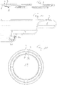
- FIG. 1 shows a cover blank 1.
- a stack 12 is shown which contains a plurality of such cover blanks, which are individually stacked and processed along the transport path by different processing stations, cover rings are first formed from the cover blanks and these can then be further processed up to the finished tear-off cover.
- the cover blanks are, for example, round disks made of coated metal and thus protected against corrosion, in particular made of coated tinplate.
- the conveyor device 22 which the cover blanks, the cover rings and the tear-off cover in the manufacturing device 20 along the transport path in the direction of the arrow A promotes from one processing station to the next processing station, is formed in particular by two parallel toothed belts on which receptacles for the cover blanks or cover rings are provided, as the person skilled in the art knows WO 2006/017953 known. This is also not explained further here.
- the blank to be processed is lifted from the conveyor device and processed by the processing station and returned to the conveyor device. This is indicated with arrows pointing up and down at the processing stations.
- the drive of the machining stations is indicated below the conveyor. This is used to raise and lower the blanks and cover rings and to carry out the respective processing steps.
- a cover ring 2 is first formed from the cover blank 1 by cutting out a central part 30 of the blank and disposing of it as waste. This forms the removal opening of the tear-open cover, which is closed with the tear-off film in a later manufacturing step.
- a sealing flange 7 remains adjacent to the removal opening 15.
- the metal material lies bare at the cut edge 31 or the sheet metal of the cover ring 2 is no longer protected there by the coating.
- a processing station 24 the edge of the removal opening is pulled up to form a collar 4 and this collar is rolled in a further processing station 25 so that a so-called retort curl 5 is formed.
- the shape of the curl or the retort curl can be different.
- the curl that forms the edge of the removal opening ensures that the user of the can is protected from the sharp-edged cut edge when removing the contents of the can.
- the tear-off film 8 is sealed onto the sealing flange, which can be done in two stages with a pre-sealing station 27 and a main sealing station 28.
- the sealing process is also known to the person skilled in the art and is not explained further here. Further processing stations can follow in which the sealing film is embossed, the tear-off tab is positioned and a leak test is carried out. This is also known to the person skilled in the art and is not explained further here.
- finished tear-off lids 10 are dispensed, the removal opening 15 of which is spanned by a tear-off film 8, which is sealed on the sealing flange 7.
- the edge of the removal opening 15 is formed by a retort curl 5 which is bent upwards and outwards.
- the finished tear-off lid 10 can be attached to a can jacket (shown in FIG Figure 5 is only indicated with a wall part 11) are attached and thus closes the box. This takes place in the bottling plant in which the can has been filled with a product. The filled can can be opened later by pulling the The tear-off film is torn away from the cover ring by means of its tear-off tab 18, with the result that the removal opening 15 is open.
- tear-off lids have proven themselves.
- the container which is closed with the tear-off lid, contains a liquid, corrosive filling material, such as salt water, for example, the bare cut edge 31 can corrode.
- a liquid, corrosive filling material such as salt water
- the bare cut edge 31 can corrode.
- the curling upwards and outwards and the overlap with the tear-off film in the illustrated tear-off lid with retort-curl provide a certain protection against the influence of the product and the bare or possibly corroded cut edge is also not visible, but can ever However, depending on the aggressiveness of the product and the storage time of the filled container, traces of corrosion can still be seen.
- EP-A-1 153 840 it is proposed that the tear-off film is also sealed on the curl itself, as a result of which the cut edge of the can contents is protected by a seal.
- EP-B 2 055 736 it is known to provide an outward curl in a container at the mouth of the container, so that the cut edge does not come into contact with water. It is proposed to protect the cut edge there with a modified hotmelt material which contains a thermoplastic elastomer.
- the invention is based on the object of creating a tear-open cover which does not have the disadvantages mentioned and which can be produced industrially at high rates and quality at low cost.
- the thickness of the band-shaped seal is preferably between 0.05 mm and 0.5 mm and in particular is approximately 0.1 mm.
- the height of the seal can be 1 mm to 3 mm.
- Figures 7 and 8 show a cover ring in which the processing step of drawing the edge of the removal opening to form the collar 4 has already taken place. This took place in the processing station 24.
- an inward curvature has been produced, which is the later Rolling up to form the retort curl is facilitated.
- a plastic layer in the form of a tape 32 has been applied to the inside 40 of the collar 4 in one work step. This plastic layer is preferably applied in a separate processing station 29, as in FIG Figure 13 shown. This processing station 29 is arranged between the pulling station 24 and the rolling station 25.
- the band 32 made of the plastic layer forms a seal for the cut edge 31 when it is rolled up, which is shown below.
- the band 32 is made of a plastic and preferably the band is made of a thermoplastic elastomer (TPE).
- TPE thermoplastic elastomer
- Such TPE plastics are commercially available and, in particular, also commercially available in qualities that reliably withstand the sterilization temperature during the sterilization of the filled container, so that the seal formed by the tape is retained during the sterilization.
- the band is preferably of uniform thickness over the entire height of the band. It is provided as a thin strip, which preferably has a thickness d in the range from 0.05 millimeters to 0.2 millimeters, preferably a thickness of approximately 0.1 millimeters.
- the height H of the band can be, for example, 1 to 3 mm.
- the cover ring is preferred in the processing station 29 ( Figures 12 and 13 ) moves in rotation and thereby moves the inside 40 of the collar 4 past the outlet opening of a spray nozzle which is statically arranged during application and from which the plastic exits.
- the cover ring is thus raised at the processing station 29, set in rotation and the application is activated when the cover ring has reached the correct position in relation to the outlet opening.
- the cover ring with the belt 32 is moved back down to the conveyor device, the rotation being terminated so that the cover ring can be placed back onto the receptacles of the conveyor device. Then it is conveyed to the roll-in station 25.
- the plastic of the band 32 cools down as soon as it is applied to the cover ring and solidifies so that the plastic does not flow during further conveyance and the band is stable in the form shown.
- a coolant for example in the form of a fan, can be provided in the application station or processing station 29.
- the cover ring can be rotated at a high rotational speed when the thin plastic tape is applied, which is understood to mean a rotation of more than 200 revolutions per minute.
- a preferred speed of rotation is in the range from 400 to 600 per minute.
- the distance between the application opening or the spray nozzle and the inside 40 of the collar 4 remains essentially constant when the liquid plastic is sprayed on, so that the thickness of the strip 32 is essentially constant and its small thickness is possible.
- This can take place, for example, in that the cover ring 2 is precisely centered on a receptacle in the processing station 29 and the spray nozzle with the discharge opening is at a defined distance from this receptacle.
- the band 32 is positioned on the inside 40 of the collar 4 that it is closer to the plane of the sealing flange 7 than to the cutting edge 31.
- the positioning and dimensioning of the band is approximately such that the band 32 is the lower third of the Collar 4 until the lower half of the collar 4 is covered.
- a greater height H of the tape is possible, but then the material expenditure for the plastic used increases without this being necessary for further processing or for protecting the cut edge. In practice, the height H will be approx. 1 mm to 3 mm.
- the cover ring provided with the plastic band is provided with a retort curl 5 in the processing station 25 in a known manner.
- This station 25 works according to the state of the art with the known rolling tools, so that this does not have to be explained in detail here, since this is known to the person skilled in the art. A modification which is obvious to a person skilled in the art may arise in the case of the tools if the collar 4 has already been pre-bent at its upper edge 34 for curling, which is preferred.
- the band 32 forms a seal which prevents the entry of liquid into the interior of the retort-curl.
- the bare cut edge 31 is protected against the influence of a liquid in the can. It does not matter whether the curling takes place in such a way that the cut edge 31 is partially embedded in the band 32, as shown, or whether it is only in contact with the band 32. Even the opposite, that the cut edge 31 cuts through the band 32 and rests against the metal of the inside 40, does not interfere with the function of the band 32.
- the usual manufacturing tolerances play a role in the formation of the retort curls 5 do not matter.
- the top view 12 shows the cover ring as it is conveyed into the sealing station 27, in which the tear-off film is sealed over the removal opening.
- Figure 13 shows the production device 20 for the tear-off lid, in which a processing station 29 is provided for applying the tape 32 to the lid ring.
- the processing station 29 is preferably according to Figure 12 and the Figures 14 to 21 educated.
- Figure 12 shows a support 50 which is adapted to the cover rings 2 in terms of diameter and shape.
- a cover ring 2 rests with its sealing flange 7 on the upper side of the support 50.
- the support 50 can be moved up and down in a known manner as in the other processing stations, so that the support can be moved downwards in the direction of arrow C in the drawing, whereby the support is lowered under the receptacles for the cover ring of the conveyor device 22, whereby the cover ring is returned to the conveyor so that it can be transported to the next processing station 25.
- the next cover ring which is to be received in the processing station 29, is received by the receptacle 50 or lifted off the conveyor device when the receptacle 50 is moved upwards again in the direction of the arrow B.
- This is basically known to the person skilled in the art in a similar manner from the other processing stations and the drive for moving the support 50 up and down is only shown schematically as box 58.
- This drive can be designed electrically and / or pneumatically in a known manner.
- the support 50 is resiliently displaceable in the horizontal direction in the direction of the arrow EF with respect to the vertical central axis 55.
- This can be done in a number of ways and is solved in the present example in such a way that a central conical holder 52 is provided which is fixed in the position of the central axis 55 (but can be rotated about this, which will be explained later) and that elastic spring means, e.g. in the form of a circumferential plastic hose 54 are provided which allow the support 50 to move horizontally in the direction of the double arrow EF by a few tenths of a millimeter to a millimeter or to move perpendicular to the central axis 55.
- the spray nozzle 46 which sprays the plastic material to form the band 32 against the inside 40 of the collar 4 of the cover ring 2, on the other hand, is fixed in its application position (but can be moved into it, which will be explained below).
- the distance from the spray nozzle 46 to the inside 40 is kept constant during the application of the plastic material in that a roller 45 rotatable about a vertical axis of rotation is arranged adjacent to the support 50.
- the position of the axis of rotation 47 in the processing station 29 is fixed and is defined in relation to the spray nozzle in its application position, whereby the plastic is applied with a defined thickness.
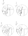
- the displacement drive 48 by means of which the spray nozzle 46 can be displaced in the direction of the double arrow EF, is shown as a box 48 and is, for example, an electric motor or electromagnetic or pneumatic design. This shift of the spray nozzle is still based on the Figures 14 to 21 shown in more detail.
- the cover ring 2 is positioned centrally to the axis 55 by the spring means 54.
- the spray nozzle 46 has been positioned by its drive 48 to the axis 55 or in the direction E, which is in the Figures 14 and 15 as well as 18 and 19 can be seen. In this position, the spray nozzle can dip into the cover ring 2 when it is lifted in the direction of arrow B. There is also enough space or space for the preferred inwardly pointing curvature of the edge 34 of the collar 4 The spray nozzle is no obstacle for the lifting movement of such a cover ring in this retracted position.
- the cover ring 2 or the support 50 and its holder 52 is set in rotation about the axis 55 by the drive 58, for example at the mentioned speed of rotation of 600 per minute.
- the drive 58 for example at the mentioned speed of rotation of 600 per minute.
- the cover ring 2 At the end of the lifting movement of the cover ring 2, it comes into contact with the outside of the collar 4 with the outside of the roller 45, since the roller 45 is arranged in the processing station so that it protrudes into the area occupied by the lifted cover ring.
- the Figures 14 and 18th show the position when lifting just before the collar 4 touches the roller 45.
- the Figures 15 and 19th show the position in which the lifting movement is complete and the collar 4 rests against the roller 45. Since the position of the roller 45 in the processing station 29 is precisely defined in the horizontal direction, the position of the collar 4 where it contacts the roller 45 is also precisely defined. Thanks to the spring means 54, the cover ring can adjust itself in the horizontal position so that it takes over the position of the roller 45.
- the spray nozzle 46 When the lifting is finished and the cover ring has the Figures 12 , 15th and 19th
- the spray nozzle 46 is moved in the direction F by its drive 48 and assumes its fixed application position. Since the position of the roller 45 in the processing station is precisely given in its distance from the spray nozzle, the inside 40 of the collar 4 opposite the spray nozzle is also positioned at a precise distance for spraying the plastic material onto the inside 40 when the spray nozzle 46 is in its end position Direction F has reached what is in the Figures 16 and 20th is shown.
- the recess 49 in the spray nozzle 46 allows the spray nozzle 46 to move up to the collar 4 despite its curvature at the end 34.
- the spray nozzle 46 can be supplied with the liquid, melted TPE plastic in a basically known manner by melting and extruding the plastic in an extruder 60 and, for example, feeding it to the processing station in liquid and pressurized form through a heated hose line 61. This is only indicated schematically with lines, so that the specific design of the entry of the line into the head containing the spray nozzle is not shown.
- a controllably openable and closable valve 62 which is preferably also heated, causes the beginning and the end of the injection of the plastic.
- a controller 63 can control the described sequence of lifting the conveyor, rotating the support with the cover ring around the axis 55 and moving the spray nozzle 46 and the start and end of spraying and moving the spray nozzle back, stopping the rotation and lowering the support Taxes.
- This control can be a control provided at the processing station 29 or is a control common to several or all of the processing stations and the conveying means 22.
- FIGS 14 to 17 show an example of the drive 48 of the spray nozzle 46 in more detail. This can be moved horizontally in a linear guide in the direction E - F, which is effected here via an eccentric drive.
- the positioning of the spray nozzle to the inside of the collar 4 is shown enlarged.
- the channel for the plastic inside the spray nozzle 46 is also shown with broken lines.
- the displacement of the support 50 and thus of the cover ring 2 when it comes into contact with the outside of the roller 45 is shown in FIG Figure 19 indicated by the arrows G.
Applications Claiming Priority (3)
| Application Number | Priority Date | Filing Date | Title |
|---|---|---|---|
| CH00643/14A CH709571A1 (de) | 2014-04-29 | 2014-04-29 | Verfahren und Vorrichtung zur Herstellung von Aufreissdeckeln sowie ein Aufreissdeckel. |
| PCT/CH2015/000042 WO2015164986A1 (de) | 2014-04-29 | 2015-03-16 | Verfahren und vorrichtung zur herstellung von aufreissdeckeln sowie ein aufreissdeckel |
| EP15712037.9A EP3137240B1 (de) | 2014-04-29 | 2015-03-16 | Verfahren und vorrichtung zur herstellung von aufreissdeckeln |
Related Parent Applications (1)
| Application Number | Title | Priority Date | Filing Date |
|---|---|---|---|
| EP15712037.9A Division EP3137240B1 (de) | 2014-04-29 | 2015-03-16 | Verfahren und vorrichtung zur herstellung von aufreissdeckeln |
Publications (1)
| Publication Number | Publication Date |
|---|---|
| EP3760333A1 true EP3760333A1 (de) | 2021-01-06 |
Family
ID=52736790
Family Applications (2)
| Application Number | Title | Priority Date | Filing Date |
|---|---|---|---|
| EP20191527.9A Withdrawn EP3760333A1 (de) | 2014-04-29 | 2015-03-16 | Aufreissdeckel |
| EP15712037.9A Active EP3137240B1 (de) | 2014-04-29 | 2015-03-16 | Verfahren und vorrichtung zur herstellung von aufreissdeckeln |
Family Applications After (1)
| Application Number | Title | Priority Date | Filing Date |
|---|---|---|---|
| EP15712037.9A Active EP3137240B1 (de) | 2014-04-29 | 2015-03-16 | Verfahren und vorrichtung zur herstellung von aufreissdeckeln |
Country Status (9)
| Country | Link |
|---|---|
| US (2) | US10494139B2 (zh) |
| EP (2) | EP3760333A1 (zh) |
| JP (1) | JP6680693B2 (zh) |
| CN (2) | CN106458397B (zh) |
| CH (1) | CH709571A1 (zh) |
| ES (1) | ES2823848T3 (zh) |
| PT (1) | PT3137240T (zh) |
| TW (1) | TWI647157B (zh) |
| WO (1) | WO2015164986A1 (zh) |
Families Citing this family (6)
| Publication number | Priority date | Publication date | Assignee | Title |
|---|---|---|---|---|
| CH713744A2 (de) * | 2017-04-21 | 2018-10-31 | Soudronic Ag | Verfahren und Vorrichtung zur Herstellung von Aufreissdeckeln sowie ein Aufreissdeckel. |
| FR3072660B1 (fr) | 2017-10-20 | 2019-11-22 | Ardagh Mp Group Netherlands B.V. | Couvercle pour boite de conserve metallique, comprenant un anneau metallique et membrane pelable thermoscellee |
| CN109413562B (zh) * | 2018-12-29 | 2021-08-27 | 歌尔股份有限公司 | 前盖的加工方法、前盖和发声装置 |
| CH716413A1 (de) * | 2019-07-18 | 2021-01-29 | Soudronic Ag | Verfahren und Vorrichtung zur Herstellung von Aufreissdeckeln sowie Aufreissdeckel. |
| CH716493A1 (de) * | 2019-08-13 | 2021-02-15 | Soudronic Ag | Aufreissdeckel. |
| DE102020128491A1 (de) * | 2020-10-29 | 2022-05-05 | Top Cap Holding Gmbh | Dosendeckel und Verfahren zum Herstellen eines Dosendeckels |
Citations (6)
| Publication number | Priority date | Publication date | Assignee | Title |
|---|---|---|---|---|
| DE9203953U1 (zh) | 1992-03-24 | 1992-07-23 | Alcan Rorschach Ag, Rorschach, Ch | |
| DE29817592U1 (de) | 1998-10-02 | 1998-11-26 | Union Deutsche Lebensmittelwer | Dose |
| EP1153840A1 (de) | 2000-05-10 | 2001-11-14 | Rasselstein Hoesch GmbH | Verfahren zum Herstellen eines Ringteils aus Blech für einen Dosendeckel |
| WO2002079041A1 (es) | 2001-03-29 | 2002-10-10 | Industrias Alimentarias De Navarra, S.A. | Cierre para latas, en especial de conserva |
| WO2006017953A1 (de) | 2004-08-18 | 2006-02-23 | Soudronic Ag | Verfahren und vorrichtung zum fördern von zu bearbeitenden gegenständen |
| EP2055736B1 (en) | 2006-08-21 | 2011-05-18 | Toyo Seikan Kaisha, Ltd. | Hotmelt composition for metal can and metal can utilizing the same |
Family Cites Families (20)
| Publication number | Priority date | Publication date | Assignee | Title |
|---|---|---|---|---|
| US4010703A (en) * | 1975-12-17 | 1977-03-08 | The Continental Group, Inc. | End lining with hot melt |
| US4026226A (en) * | 1976-03-01 | 1977-05-31 | American Can Company | Press apparatus and method utilizing same |
| US3999495A (en) * | 1976-04-02 | 1976-12-28 | American Can Company | Can end transfer mechanism |
| EP0007487B1 (de) * | 1978-07-10 | 1981-11-11 | Del Bon, Franco | Versiegelte Dose und vorgeformtes Verschlusselement dafür sowie Verfahren und Vorrichtungen zu deren Herstellung |
| CH654542A5 (de) * | 1982-04-05 | 1986-02-28 | Sandherr Packungen Ag | Verschlussdeckel fuer sterilisierbare dosen. |
| US4648528A (en) * | 1985-05-29 | 1987-03-10 | Aluminum Company Of America | Easy opening container end closure |
| CN1066037A (zh) | 1991-04-22 | 1992-11-11 | 天龙化学工业株式会社 | 广口容器的盖装置 |
| US6301766B1 (en) | 1998-01-12 | 2001-10-16 | Tempress Technologies, Inc. | Method for metal working using high pressure fluid pulses |
| JP4375704B2 (ja) * | 2003-01-27 | 2009-12-02 | 大和製罐株式会社 | 金属缶の開口カール部製造方法 |
| US7134824B2 (en) * | 2002-06-05 | 2006-11-14 | Industrias Peñalver S.L. | Curling-sealing compound lining machine for non-circular metal lids of containers |
| US7055713B2 (en) * | 2002-11-12 | 2006-06-06 | Sonoco Development, Inc. | Easy-opening closure for retortable container |
| ES2246634B1 (es) | 2003-04-08 | 2007-04-16 | Industrias Alimentarias De Navarra, S.A. | Cierre para latas. |
| EP1559655A1 (en) * | 2004-01-29 | 2005-08-03 | Impress Group B.V. | Container and method for producing such a container |
| WO2006097005A1 (de) * | 2005-03-17 | 2006-09-21 | Soudronic Ag | Aufreissdeckel und verfahren zu dessen herstellung |
| EP1800770A1 (en) * | 2005-12-23 | 2007-06-27 | Crown Packaging Technology, Inc | Can body with a sealing compound placed on a step or flange and method of forming such a can body |
| CH701451A2 (de) * | 2009-07-09 | 2011-01-14 | Soudronic Ag | Verfahren und Vorrichtung zur Herstellung von Aufreissdeckeln. |
| US8695832B2 (en) * | 2010-02-02 | 2014-04-15 | Klaus Thielen | Can lid and method for producing a can lid |
| CH704695A1 (de) | 2011-03-25 | 2012-09-28 | Soudronic Ag | Vorrichtung und Verfahren zur Herstellung von Aufreissdeckeln. |
| US8826850B2 (en) * | 2012-04-30 | 2014-09-09 | Stolle Machinery Company, Llc | Linear liner and associated method |
| CN202967034U (zh) * | 2012-11-20 | 2013-06-05 | 东莞市精丽制罐有限公司 | 食品盒盒身盒底卷封结构 |
-
2014
- 2014-04-29 CH CH00643/14A patent/CH709571A1/de not_active Application Discontinuation
-
2015
- 2015-03-16 EP EP20191527.9A patent/EP3760333A1/de not_active Withdrawn
- 2015-03-16 CN CN201580022960.0A patent/CN106458397B/zh not_active Expired - Fee Related
- 2015-03-16 PT PT157120379T patent/PT3137240T/pt unknown
- 2015-03-16 ES ES15712037T patent/ES2823848T3/es active Active
- 2015-03-16 JP JP2016565140A patent/JP6680693B2/ja not_active Expired - Fee Related
- 2015-03-16 WO PCT/CH2015/000042 patent/WO2015164986A1/de active Application Filing
- 2015-03-16 CN CN201910153700.7A patent/CN109794563A/zh active Pending
- 2015-03-16 EP EP15712037.9A patent/EP3137240B1/de active Active
- 2015-03-16 US US15/304,904 patent/US10494139B2/en not_active Expired - Fee Related
- 2015-03-30 TW TW104110165A patent/TWI647157B/zh not_active IP Right Cessation
-
2019
- 2019-04-30 US US16/398,792 patent/US11142369B2/en active Active
Patent Citations (6)
| Publication number | Priority date | Publication date | Assignee | Title |
|---|---|---|---|---|
| DE9203953U1 (zh) | 1992-03-24 | 1992-07-23 | Alcan Rorschach Ag, Rorschach, Ch | |
| DE29817592U1 (de) | 1998-10-02 | 1998-11-26 | Union Deutsche Lebensmittelwer | Dose |
| EP1153840A1 (de) | 2000-05-10 | 2001-11-14 | Rasselstein Hoesch GmbH | Verfahren zum Herstellen eines Ringteils aus Blech für einen Dosendeckel |
| WO2002079041A1 (es) | 2001-03-29 | 2002-10-10 | Industrias Alimentarias De Navarra, S.A. | Cierre para latas, en especial de conserva |
| WO2006017953A1 (de) | 2004-08-18 | 2006-02-23 | Soudronic Ag | Verfahren und vorrichtung zum fördern von zu bearbeitenden gegenständen |
| EP2055736B1 (en) | 2006-08-21 | 2011-05-18 | Toyo Seikan Kaisha, Ltd. | Hotmelt composition for metal can and metal can utilizing the same |
Also Published As
| Publication number | Publication date |
|---|---|
| EP3137240A1 (de) | 2017-03-08 |
| JP6680693B2 (ja) | 2020-04-15 |
| TWI647157B (zh) | 2019-01-11 |
| CN106458397A (zh) | 2017-02-22 |
| TW201604095A (zh) | 2016-02-01 |
| US10494139B2 (en) | 2019-12-03 |
| US11142369B2 (en) | 2021-10-12 |
| EP3137240B1 (de) | 2020-09-02 |
| CH709571A1 (de) | 2015-10-30 |
| PT3137240T (pt) | 2020-11-09 |
| US20190256248A1 (en) | 2019-08-22 |
| JP2017520402A (ja) | 2017-07-27 |
| CN106458397B (zh) | 2019-03-08 |
| US20170183121A1 (en) | 2017-06-29 |
| ES2823848T3 (es) | 2021-05-10 |
| WO2015164986A1 (de) | 2015-11-05 |
| CN109794563A (zh) | 2019-05-24 |
Similar Documents
| Publication | Publication Date | Title |
|---|---|---|
| EP3137240B1 (de) | Verfahren und vorrichtung zur herstellung von aufreissdeckeln | |
| EP2151286A2 (de) | Einrichtung und Verfahren zur Herstellung von Deckeln mit Aufreissfolie | |
| DE60219123T2 (de) | Vorrichtung zum Ausschneiden einer Reihe von Membranverschlüssen aus einer Bahn und zur Fixierung dieser auf einer Reihe von gefüllten Behältern | |
| EP1858767B1 (de) | Aufreissdeckel und verfahren zu dessen herstellung | |
| EP3554734B1 (de) | Verfahren und vorrichtung zur herstellung von aufreissdeckeln sowie ein aufreissdeckel | |
| WO2019086483A1 (de) | Verfahren und vorrichtung zum aufbringen von etiketten auf zigarettenpackungen | |
| EP2208554B1 (de) | Verfahren und Vorrichtung zur Herstellung von Aufreissdeckeln | |
| DE2810899A1 (de) | Verfahren zur herstellung und fuellung eines behaelters, wie becher oder flasche, aus kunststoff | |
| EP2558231B1 (de) | Anordnung zur bildung einer bandschlaufe und verfahren und vorrichtung zur herstellung von aufreissdeckeln | |
| EP2783993B1 (de) | Vorrichtung zum Etikettieren von Gefäßen und Verfahren zum Steuern der Vorrichtung zum Etikettieren von Gefäßen | |
| DE3023808A1 (de) | Verfahren und vorrichtung zur herstellung eines luftdicht verschlossenen behaelters | |
| DE2806770A1 (de) | Verfahren und vorrichtung zum verschweissen einer deckfolie und eines traegers, insbesondere eines behaelters, aus thermoplastischem material sowie damit erhaltenes produkt | |
| EP3642117B1 (de) | Vorrichtung zur verpackung, insbesondere von obst und gemüse | |
| WO2006092073A1 (de) | Deckel für eine verpackung, herstellungsverfahren und -vorrichtung dafür | |
| CH716413A1 (de) | Verfahren und Vorrichtung zur Herstellung von Aufreissdeckeln sowie Aufreissdeckel. | |
| EP3238919B1 (de) | Rundläufer-maschine und verfahren zum siegeln von folienbeuteln | |
| DE19524427A1 (de) | Behälter zur Verpackung von Getränken, Vorrichtung und Verfahren zur Herstellung | |
| CH705595A1 (de) | Verfahren und Vorrichtung zur Herstellung von Aufreissdeckeln. | |
| EP0114049B1 (de) | Verfahren und Vorrichtung zum Herstellen eines Behälters aus Karton und damit hergestellter Behälter | |
| DE19624042A1 (de) | Verfahren zur Herstellung einer Verpackung sowie danach herstellbare Verpackung | |
| DE1757860A1 (de) | Schraubverschluss fuer Behaelter von Pharmazeutika od.dgl. | |
| EP1416068A2 (de) | Verfahren und Anlage zur Antikorrosionsbehandlung von Ventiltellern für Spenderbehälter | |
| DE3039396A1 (de) | Verfahren und vorrichtung zum einbringen von dichteinlagen in behaelterverschluesse | |
| CH701105A1 (de) | Verfahren und Vorrichtung zur Herstellung von Aufreissdeckeln. |
Legal Events
| Date | Code | Title | Description |
|---|---|---|---|
| PUAI | Public reference made under article 153(3) epc to a published international application that has entered the european phase |
Free format text: ORIGINAL CODE: 0009012 |
|
| STAA | Information on the status of an ep patent application or granted ep patent |
Free format text: STATUS: THE APPLICATION HAS BEEN PUBLISHED |
|
| AC | Divisional application: reference to earlier application |
Ref document number: 3137240 Country of ref document: EP Kind code of ref document: P |
|
| AK | Designated contracting states |
Kind code of ref document: A1 Designated state(s): AL AT BE BG CH CY CZ DE DK EE ES FI FR GB GR HR HU IE IS IT LI LT LU LV MC MK MT NL NO PL PT RO RS SE SI SK SM TR |
|
| STAA | Information on the status of an ep patent application or granted ep patent |
Free format text: STATUS: THE APPLICATION IS DEEMED TO BE WITHDRAWN |
|
| 18D | Application deemed to be withdrawn |
Effective date: 20210707 |