EP3760333A1 - Tear-open cover - Google Patents
Tear-open cover Download PDFInfo
- Publication number
- EP3760333A1 EP3760333A1 EP20191527.9A EP20191527A EP3760333A1 EP 3760333 A1 EP3760333 A1 EP 3760333A1 EP 20191527 A EP20191527 A EP 20191527A EP 3760333 A1 EP3760333 A1 EP 3760333A1
- Authority
- EP
- European Patent Office
- Prior art keywords
- tear
- cover
- cover ring
- spray nozzle
- plastic
- Prior art date
- Legal status (The legal status is an assumption and is not a legal conclusion. Google has not performed a legal analysis and makes no representation as to the accuracy of the status listed.)
- Withdrawn
Links
Images


Classifications
-
- B—PERFORMING OPERATIONS; TRANSPORTING
- B65—CONVEYING; PACKING; STORING; HANDLING THIN OR FILAMENTARY MATERIAL
- B65D—CONTAINERS FOR STORAGE OR TRANSPORT OF ARTICLES OR MATERIALS, e.g. BAGS, BARRELS, BOTTLES, BOXES, CANS, CARTONS, CRATES, DRUMS, JARS, TANKS, HOPPERS, FORWARDING CONTAINERS; ACCESSORIES, CLOSURES, OR FITTINGS THEREFOR; PACKAGING ELEMENTS; PACKAGES
- B65D53/00—Sealing or packing elements; Sealings formed by liquid or plastics material
- B65D53/10—Sealing or packing elements; Sealings formed by liquid or plastics material characterised by special adaptation to acid-proof vessels
-
- B—PERFORMING OPERATIONS; TRANSPORTING
- B65—CONVEYING; PACKING; STORING; HANDLING THIN OR FILAMENTARY MATERIAL
- B65D—CONTAINERS FOR STORAGE OR TRANSPORT OF ARTICLES OR MATERIALS, e.g. BAGS, BARRELS, BOTTLES, BOXES, CANS, CARTONS, CRATES, DRUMS, JARS, TANKS, HOPPERS, FORWARDING CONTAINERS; ACCESSORIES, CLOSURES, OR FITTINGS THEREFOR; PACKAGING ELEMENTS; PACKAGES
- B65D17/00—Rigid or semi-rigid containers specially constructed to be opened by cutting or piercing, or by tearing of frangible members or portions
- B65D17/50—Non-integral frangible members applied to, or inserted in, preformed openings, e.g. tearable strips or plastic plugs
- B65D17/501—Flexible tape or foil-like material
- B65D17/502—Flexible tape or foil-like material applied to the external part of the container wall only
-
- B—PERFORMING OPERATIONS; TRANSPORTING
- B21—MECHANICAL METAL-WORKING WITHOUT ESSENTIALLY REMOVING MATERIAL; PUNCHING METAL
- B21D—WORKING OR PROCESSING OF SHEET METAL OR METAL TUBES, RODS OR PROFILES WITHOUT ESSENTIALLY REMOVING MATERIAL; PUNCHING METAL
- B21D51/00—Making hollow objects
- B21D51/16—Making hollow objects characterised by the use of the objects
- B21D51/38—Making inlet or outlet arrangements of cans, tins, baths, bottles, or other vessels; Making can ends; Making closures
- B21D51/383—Making inlet or outlet arrangements of cans, tins, baths, bottles, or other vessels; Making can ends; Making closures scoring lines, tear strips or pulling tabs
-
- B—PERFORMING OPERATIONS; TRANSPORTING
- B21—MECHANICAL METAL-WORKING WITHOUT ESSENTIALLY REMOVING MATERIAL; PUNCHING METAL
- B21D—WORKING OR PROCESSING OF SHEET METAL OR METAL TUBES, RODS OR PROFILES WITHOUT ESSENTIALLY REMOVING MATERIAL; PUNCHING METAL
- B21D51/00—Making hollow objects
- B21D51/16—Making hollow objects characterised by the use of the objects
- B21D51/38—Making inlet or outlet arrangements of cans, tins, baths, bottles, or other vessels; Making can ends; Making closures
- B21D51/44—Making closures, e.g. caps
- B21D51/443—Making closures, e.g. caps easily removable closures, e.g. by means of tear strips
-
- B—PERFORMING OPERATIONS; TRANSPORTING
- B21—MECHANICAL METAL-WORKING WITHOUT ESSENTIALLY REMOVING MATERIAL; PUNCHING METAL
- B21D—WORKING OR PROCESSING OF SHEET METAL OR METAL TUBES, RODS OR PROFILES WITHOUT ESSENTIALLY REMOVING MATERIAL; PUNCHING METAL
- B21D51/00—Making hollow objects
- B21D51/16—Making hollow objects characterised by the use of the objects
- B21D51/38—Making inlet or outlet arrangements of cans, tins, baths, bottles, or other vessels; Making can ends; Making closures
- B21D51/44—Making closures, e.g. caps
- B21D51/46—Placing sealings or sealing material
-
- B—PERFORMING OPERATIONS; TRANSPORTING
- B65—CONVEYING; PACKING; STORING; HANDLING THIN OR FILAMENTARY MATERIAL
- B65D—CONTAINERS FOR STORAGE OR TRANSPORT OF ARTICLES OR MATERIALS, e.g. BAGS, BARRELS, BOTTLES, BOXES, CANS, CARTONS, CRATES, DRUMS, JARS, TANKS, HOPPERS, FORWARDING CONTAINERS; ACCESSORIES, CLOSURES, OR FITTINGS THEREFOR; PACKAGING ELEMENTS; PACKAGES
- B65D17/00—Rigid or semi-rigid containers specially constructed to be opened by cutting or piercing, or by tearing of frangible members or portions
-
- B—PERFORMING OPERATIONS; TRANSPORTING
- B65—CONVEYING; PACKING; STORING; HANDLING THIN OR FILAMENTARY MATERIAL
- B65D—CONTAINERS FOR STORAGE OR TRANSPORT OF ARTICLES OR MATERIALS, e.g. BAGS, BARRELS, BOTTLES, BOXES, CANS, CARTONS, CRATES, DRUMS, JARS, TANKS, HOPPERS, FORWARDING CONTAINERS; ACCESSORIES, CLOSURES, OR FITTINGS THEREFOR; PACKAGING ELEMENTS; PACKAGES
- B65D53/00—Sealing or packing elements; Sealings formed by liquid or plastics material
-
- B—PERFORMING OPERATIONS; TRANSPORTING
- B65—CONVEYING; PACKING; STORING; HANDLING THIN OR FILAMENTARY MATERIAL
- B65D—CONTAINERS FOR STORAGE OR TRANSPORT OF ARTICLES OR MATERIALS, e.g. BAGS, BARRELS, BOTTLES, BOXES, CANS, CARTONS, CRATES, DRUMS, JARS, TANKS, HOPPERS, FORWARDING CONTAINERS; ACCESSORIES, CLOSURES, OR FITTINGS THEREFOR; PACKAGING ELEMENTS; PACKAGES
- B65D2517/00—Containers specially constructed to be opened by cutting, piercing or tearing of wall portions, e.g. preserving cans or tins
- B65D2517/0001—Details
- B65D2517/001—Action for opening container
- B65D2517/0013—Action for opening container pull-out tear panel, e.g. by means of a tear-tab
-
- B—PERFORMING OPERATIONS; TRANSPORTING
- B65—CONVEYING; PACKING; STORING; HANDLING THIN OR FILAMENTARY MATERIAL
- B65D—CONTAINERS FOR STORAGE OR TRANSPORT OF ARTICLES OR MATERIALS, e.g. BAGS, BARRELS, BOTTLES, BOXES, CANS, CARTONS, CRATES, DRUMS, JARS, TANKS, HOPPERS, FORWARDING CONTAINERS; ACCESSORIES, CLOSURES, OR FITTINGS THEREFOR; PACKAGING ELEMENTS; PACKAGES
- B65D2517/00—Containers specially constructed to be opened by cutting, piercing or tearing of wall portions, e.g. preserving cans or tins
- B65D2517/50—Non-integral frangible members applied to, or inserted in, a preformed opening
- B65D2517/5002—Details of flexible tape or foil-like material
- B65D2517/5008—Details of flexible tape or foil-like material with a sealing coat
-
- B—PERFORMING OPERATIONS; TRANSPORTING
- B65—CONVEYING; PACKING; STORING; HANDLING THIN OR FILAMENTARY MATERIAL
- B65D—CONTAINERS FOR STORAGE OR TRANSPORT OF ARTICLES OR MATERIALS, e.g. BAGS, BARRELS, BOTTLES, BOXES, CANS, CARTONS, CRATES, DRUMS, JARS, TANKS, HOPPERS, FORWARDING CONTAINERS; ACCESSORIES, CLOSURES, OR FITTINGS THEREFOR; PACKAGING ELEMENTS; PACKAGES
- B65D2517/00—Containers specially constructed to be opened by cutting, piercing or tearing of wall portions, e.g. preserving cans or tins
- B65D2517/50—Non-integral frangible members applied to, or inserted in, a preformed opening
- B65D2517/504—Details of preformed openings
- B65D2517/5056—Details of preformed openings the edge of the preformed opening having a covering element or coating, e.g. to prevent cutting or for sealing purposes
Definitions
- the invention relates to a tear-off lid according to claim 1.
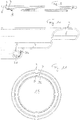
- FIG. 1 shows a cover blank 1.
- a stack 12 is shown which contains a plurality of such cover blanks, which are individually stacked and processed along the transport path by different processing stations, cover rings are first formed from the cover blanks and these can then be further processed up to the finished tear-off cover.
- the cover blanks are, for example, round disks made of coated metal and thus protected against corrosion, in particular made of coated tinplate.
- the conveyor device 22 which the cover blanks, the cover rings and the tear-off cover in the manufacturing device 20 along the transport path in the direction of the arrow A promotes from one processing station to the next processing station, is formed in particular by two parallel toothed belts on which receptacles for the cover blanks or cover rings are provided, as the person skilled in the art knows WO 2006/017953 known. This is also not explained further here.
- the blank to be processed is lifted from the conveyor device and processed by the processing station and returned to the conveyor device. This is indicated with arrows pointing up and down at the processing stations.
- the drive of the machining stations is indicated below the conveyor. This is used to raise and lower the blanks and cover rings and to carry out the respective processing steps.
- a cover ring 2 is first formed from the cover blank 1 by cutting out a central part 30 of the blank and disposing of it as waste. This forms the removal opening of the tear-open cover, which is closed with the tear-off film in a later manufacturing step.
- a sealing flange 7 remains adjacent to the removal opening 15.
- the metal material lies bare at the cut edge 31 or the sheet metal of the cover ring 2 is no longer protected there by the coating.
- a processing station 24 the edge of the removal opening is pulled up to form a collar 4 and this collar is rolled in a further processing station 25 so that a so-called retort curl 5 is formed.
- the shape of the curl or the retort curl can be different.
- the curl that forms the edge of the removal opening ensures that the user of the can is protected from the sharp-edged cut edge when removing the contents of the can.
- the tear-off film 8 is sealed onto the sealing flange, which can be done in two stages with a pre-sealing station 27 and a main sealing station 28.
- the sealing process is also known to the person skilled in the art and is not explained further here. Further processing stations can follow in which the sealing film is embossed, the tear-off tab is positioned and a leak test is carried out. This is also known to the person skilled in the art and is not explained further here.
- finished tear-off lids 10 are dispensed, the removal opening 15 of which is spanned by a tear-off film 8, which is sealed on the sealing flange 7.
- the edge of the removal opening 15 is formed by a retort curl 5 which is bent upwards and outwards.
- the finished tear-off lid 10 can be attached to a can jacket (shown in FIG Figure 5 is only indicated with a wall part 11) are attached and thus closes the box. This takes place in the bottling plant in which the can has been filled with a product. The filled can can be opened later by pulling the The tear-off film is torn away from the cover ring by means of its tear-off tab 18, with the result that the removal opening 15 is open.
- tear-off lids have proven themselves.
- the container which is closed with the tear-off lid, contains a liquid, corrosive filling material, such as salt water, for example, the bare cut edge 31 can corrode.
- a liquid, corrosive filling material such as salt water
- the bare cut edge 31 can corrode.
- the curling upwards and outwards and the overlap with the tear-off film in the illustrated tear-off lid with retort-curl provide a certain protection against the influence of the product and the bare or possibly corroded cut edge is also not visible, but can ever However, depending on the aggressiveness of the product and the storage time of the filled container, traces of corrosion can still be seen.
- EP-A-1 153 840 it is proposed that the tear-off film is also sealed on the curl itself, as a result of which the cut edge of the can contents is protected by a seal.
- EP-B 2 055 736 it is known to provide an outward curl in a container at the mouth of the container, so that the cut edge does not come into contact with water. It is proposed to protect the cut edge there with a modified hotmelt material which contains a thermoplastic elastomer.
- the invention is based on the object of creating a tear-open cover which does not have the disadvantages mentioned and which can be produced industrially at high rates and quality at low cost.
- the thickness of the band-shaped seal is preferably between 0.05 mm and 0.5 mm and in particular is approximately 0.1 mm.
- the height of the seal can be 1 mm to 3 mm.
- Figures 7 and 8 show a cover ring in which the processing step of drawing the edge of the removal opening to form the collar 4 has already taken place. This took place in the processing station 24.
- an inward curvature has been produced, which is the later Rolling up to form the retort curl is facilitated.
- a plastic layer in the form of a tape 32 has been applied to the inside 40 of the collar 4 in one work step. This plastic layer is preferably applied in a separate processing station 29, as in FIG Figure 13 shown. This processing station 29 is arranged between the pulling station 24 and the rolling station 25.
- the band 32 made of the plastic layer forms a seal for the cut edge 31 when it is rolled up, which is shown below.
- the band 32 is made of a plastic and preferably the band is made of a thermoplastic elastomer (TPE).
- TPE thermoplastic elastomer
- Such TPE plastics are commercially available and, in particular, also commercially available in qualities that reliably withstand the sterilization temperature during the sterilization of the filled container, so that the seal formed by the tape is retained during the sterilization.
- the band is preferably of uniform thickness over the entire height of the band. It is provided as a thin strip, which preferably has a thickness d in the range from 0.05 millimeters to 0.2 millimeters, preferably a thickness of approximately 0.1 millimeters.
- the height H of the band can be, for example, 1 to 3 mm.
- the cover ring is preferred in the processing station 29 ( Figures 12 and 13 ) moves in rotation and thereby moves the inside 40 of the collar 4 past the outlet opening of a spray nozzle which is statically arranged during application and from which the plastic exits.
- the cover ring is thus raised at the processing station 29, set in rotation and the application is activated when the cover ring has reached the correct position in relation to the outlet opening.
- the cover ring with the belt 32 is moved back down to the conveyor device, the rotation being terminated so that the cover ring can be placed back onto the receptacles of the conveyor device. Then it is conveyed to the roll-in station 25.
- the plastic of the band 32 cools down as soon as it is applied to the cover ring and solidifies so that the plastic does not flow during further conveyance and the band is stable in the form shown.
- a coolant for example in the form of a fan, can be provided in the application station or processing station 29.
- the cover ring can be rotated at a high rotational speed when the thin plastic tape is applied, which is understood to mean a rotation of more than 200 revolutions per minute.
- a preferred speed of rotation is in the range from 400 to 600 per minute.
- the distance between the application opening or the spray nozzle and the inside 40 of the collar 4 remains essentially constant when the liquid plastic is sprayed on, so that the thickness of the strip 32 is essentially constant and its small thickness is possible.
- This can take place, for example, in that the cover ring 2 is precisely centered on a receptacle in the processing station 29 and the spray nozzle with the discharge opening is at a defined distance from this receptacle.
- the band 32 is positioned on the inside 40 of the collar 4 that it is closer to the plane of the sealing flange 7 than to the cutting edge 31.
- the positioning and dimensioning of the band is approximately such that the band 32 is the lower third of the Collar 4 until the lower half of the collar 4 is covered.
- a greater height H of the tape is possible, but then the material expenditure for the plastic used increases without this being necessary for further processing or for protecting the cut edge. In practice, the height H will be approx. 1 mm to 3 mm.
- the cover ring provided with the plastic band is provided with a retort curl 5 in the processing station 25 in a known manner.
- This station 25 works according to the state of the art with the known rolling tools, so that this does not have to be explained in detail here, since this is known to the person skilled in the art. A modification which is obvious to a person skilled in the art may arise in the case of the tools if the collar 4 has already been pre-bent at its upper edge 34 for curling, which is preferred.
- the band 32 forms a seal which prevents the entry of liquid into the interior of the retort-curl.
- the bare cut edge 31 is protected against the influence of a liquid in the can. It does not matter whether the curling takes place in such a way that the cut edge 31 is partially embedded in the band 32, as shown, or whether it is only in contact with the band 32. Even the opposite, that the cut edge 31 cuts through the band 32 and rests against the metal of the inside 40, does not interfere with the function of the band 32.
- the usual manufacturing tolerances play a role in the formation of the retort curls 5 do not matter.
- the top view 12 shows the cover ring as it is conveyed into the sealing station 27, in which the tear-off film is sealed over the removal opening.
- Figure 13 shows the production device 20 for the tear-off lid, in which a processing station 29 is provided for applying the tape 32 to the lid ring.
- the processing station 29 is preferably according to Figure 12 and the Figures 14 to 21 educated.
- Figure 12 shows a support 50 which is adapted to the cover rings 2 in terms of diameter and shape.
- a cover ring 2 rests with its sealing flange 7 on the upper side of the support 50.
- the support 50 can be moved up and down in a known manner as in the other processing stations, so that the support can be moved downwards in the direction of arrow C in the drawing, whereby the support is lowered under the receptacles for the cover ring of the conveyor device 22, whereby the cover ring is returned to the conveyor so that it can be transported to the next processing station 25.
- the next cover ring which is to be received in the processing station 29, is received by the receptacle 50 or lifted off the conveyor device when the receptacle 50 is moved upwards again in the direction of the arrow B.
- This is basically known to the person skilled in the art in a similar manner from the other processing stations and the drive for moving the support 50 up and down is only shown schematically as box 58.
- This drive can be designed electrically and / or pneumatically in a known manner.
- the support 50 is resiliently displaceable in the horizontal direction in the direction of the arrow EF with respect to the vertical central axis 55.
- This can be done in a number of ways and is solved in the present example in such a way that a central conical holder 52 is provided which is fixed in the position of the central axis 55 (but can be rotated about this, which will be explained later) and that elastic spring means, e.g. in the form of a circumferential plastic hose 54 are provided which allow the support 50 to move horizontally in the direction of the double arrow EF by a few tenths of a millimeter to a millimeter or to move perpendicular to the central axis 55.
- the spray nozzle 46 which sprays the plastic material to form the band 32 against the inside 40 of the collar 4 of the cover ring 2, on the other hand, is fixed in its application position (but can be moved into it, which will be explained below).
- the distance from the spray nozzle 46 to the inside 40 is kept constant during the application of the plastic material in that a roller 45 rotatable about a vertical axis of rotation is arranged adjacent to the support 50.
- the position of the axis of rotation 47 in the processing station 29 is fixed and is defined in relation to the spray nozzle in its application position, whereby the plastic is applied with a defined thickness.
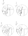
- the displacement drive 48 by means of which the spray nozzle 46 can be displaced in the direction of the double arrow EF, is shown as a box 48 and is, for example, an electric motor or electromagnetic or pneumatic design. This shift of the spray nozzle is still based on the Figures 14 to 21 shown in more detail.
- the cover ring 2 is positioned centrally to the axis 55 by the spring means 54.
- the spray nozzle 46 has been positioned by its drive 48 to the axis 55 or in the direction E, which is in the Figures 14 and 15 as well as 18 and 19 can be seen. In this position, the spray nozzle can dip into the cover ring 2 when it is lifted in the direction of arrow B. There is also enough space or space for the preferred inwardly pointing curvature of the edge 34 of the collar 4 The spray nozzle is no obstacle for the lifting movement of such a cover ring in this retracted position.
- the cover ring 2 or the support 50 and its holder 52 is set in rotation about the axis 55 by the drive 58, for example at the mentioned speed of rotation of 600 per minute.
- the drive 58 for example at the mentioned speed of rotation of 600 per minute.
- the cover ring 2 At the end of the lifting movement of the cover ring 2, it comes into contact with the outside of the collar 4 with the outside of the roller 45, since the roller 45 is arranged in the processing station so that it protrudes into the area occupied by the lifted cover ring.
- the Figures 14 and 18th show the position when lifting just before the collar 4 touches the roller 45.
- the Figures 15 and 19th show the position in which the lifting movement is complete and the collar 4 rests against the roller 45. Since the position of the roller 45 in the processing station 29 is precisely defined in the horizontal direction, the position of the collar 4 where it contacts the roller 45 is also precisely defined. Thanks to the spring means 54, the cover ring can adjust itself in the horizontal position so that it takes over the position of the roller 45.
- the spray nozzle 46 When the lifting is finished and the cover ring has the Figures 12 , 15th and 19th
- the spray nozzle 46 is moved in the direction F by its drive 48 and assumes its fixed application position. Since the position of the roller 45 in the processing station is precisely given in its distance from the spray nozzle, the inside 40 of the collar 4 opposite the spray nozzle is also positioned at a precise distance for spraying the plastic material onto the inside 40 when the spray nozzle 46 is in its end position Direction F has reached what is in the Figures 16 and 20th is shown.
- the recess 49 in the spray nozzle 46 allows the spray nozzle 46 to move up to the collar 4 despite its curvature at the end 34.
- the spray nozzle 46 can be supplied with the liquid, melted TPE plastic in a basically known manner by melting and extruding the plastic in an extruder 60 and, for example, feeding it to the processing station in liquid and pressurized form through a heated hose line 61. This is only indicated schematically with lines, so that the specific design of the entry of the line into the head containing the spray nozzle is not shown.
- a controllably openable and closable valve 62 which is preferably also heated, causes the beginning and the end of the injection of the plastic.
- a controller 63 can control the described sequence of lifting the conveyor, rotating the support with the cover ring around the axis 55 and moving the spray nozzle 46 and the start and end of spraying and moving the spray nozzle back, stopping the rotation and lowering the support Taxes.
- This control can be a control provided at the processing station 29 or is a control common to several or all of the processing stations and the conveying means 22.
- FIGS 14 to 17 show an example of the drive 48 of the spray nozzle 46 in more detail. This can be moved horizontally in a linear guide in the direction E - F, which is effected here via an eccentric drive.
- the positioning of the spray nozzle to the inside of the collar 4 is shown enlarged.
- the channel for the plastic inside the spray nozzle 46 is also shown with broken lines.
- the displacement of the support 50 and thus of the cover ring 2 when it comes into contact with the outside of the roller 45 is shown in FIG Figure 19 indicated by the arrows G.
Landscapes
- Engineering & Computer Science (AREA)
- Mechanical Engineering (AREA)
- Closures For Containers (AREA)
- Extrusion Moulding Of Plastics Or The Like (AREA)
Abstract
Ein Aufreissdeckel (10) umfasst einen umlaufenden Befestigungsabschnitt (6), einen Siegelflansch (7) mit einer auf diesem aufgesiegelten Aufreissfolie und einem um den Siegelflansch (7) umlaufenden eingerollten Rand (5), der die Entnahmeöffnung (15) seitlich begrenzt. Der eingerollte Rand weist eine bandförmige Dichtung (32) aus einem Kunststoff, insbesondere aus einem thermoplastischen Elastomer (TPE), auf, welche eine im Wesentlichen gleichmässige Dicke aufweist.A tear-open cover (10) comprises a circumferential fastening section (6), a sealing flange (7) with a tear-off film sealed on this and a rolled edge (5) which runs around the sealing flange (7) and laterally delimits the removal opening (15). The rolled edge has a band-shaped seal (32) made of a plastic, in particular made of a thermoplastic elastomer (TPE), which has a substantially uniform thickness.
Description
Die Erfindung betrifft einen Aufreissdeckel gemäss Anspruch 1.The invention relates to a tear-off lid according to claim 1.
Aufreissdeckel sind bekannt, so z.B. aus
Die Fördereinrichtung 22, welche die Deckelrohlinge, die Deckelringe und die Aufreissdeckel in der Herstellvorrichtung 20 entlang des Transportweges in Richtung des Pfeils A von einer Bearbeitungsstation zur nächsten Bearbeitungsstation fördert, wird insbesondere von zwei parallel laufenden Zahnriemen gebildet, an denen Aufnahmen für die Deckelrohlinge bzw. Deckelringe vorgesehen sind, wie dem Fachmann aus
In einer Stanzbearbeitungsstation 23 wird zunächst aus dem Deckelrohling 1 ein Deckelring 2 gebildet, indem ein mittlerer Teil 30 des Rohlings ausgeschnitten und als Abfall entsorgt wird. Damit wird die Entnahmeöffnung des Aufreissdeckels gebildet, die in einem späteren Herstellungsschritt mit der Aufreissfolie verschlossen wird. An die Entnahmeöffnung 15 anschliessend verbleibt ein Siegelflansch 7. An der Schnittkante 31 liegt das Metallmaterial blank bzw. das Blech des Deckelrings 2 ist dort nicht mehr durch die Beschichtung geschützt. In einer Bearbeitungsstation 24 wird der Rand der Entnahmeöffnung zu einem Kragen 4 nach oben gezogen und dieser Kragen wird in einer weiteren Bearbeitungsstation 25 gerollt, so dass ein sogenannter retort-curl 5 gebildet wird. Die Form der Einrollung bzw. des retort-curls kann verschieden sein. Die Einrollung, die den Rand der Entnahmeöffnung bildet, sorgt dafür, dass der Benützer der Dose bei der Entnahme des Inhalts der Dose vor der scharfkantigen Schnittkante geschützt ist.In a
Die bisherigen Herstellungsschritte sind in einer Lage durchgeführt worden, bei welcher die Deckelrohlinge und Deckelringe mit ihrer späteren Oberseite bzw. mit dem Siegelflansch 7 nach unten weisend angeordnet waren. Dies ist die bevorzugte Ausführung auch bei der vorliegenden Erfindung. Wie erwähnt, wird der Rohling bzw. der Ring in den einzelnen Bearbeitungsstationen 23, 24 und 25 von der Fördereinrichtung abgehoben, bearbeitet und wieder zurück gelegt, worauf die Fördereinrichtung Förderschritte ausführt, welche die Deckelrohlinge bzw. Deckelringe zur nächsten Bearbeitungsstation führt. Werden die Herstellungsschritte, wie dargestellt, mit nach unten weisendem Siegelflansch 7 durchgeführt, so folgt nun eine Wendestation 26, welche die Deckelringe wendet, so dass bei der weiteren Bearbeitung der Siegelflansch 7 nach der Wendestation in der Fördereinrichtung 22 und in den Bearbeitungsstationen oben liegt.The previous manufacturing steps have been carried out in a position in which the cover blanks and cover rings were arranged with their later top or with the sealing
Danach wird die Aufreissfolie 8 auf den Siegelflansch aufgesiegelt, was zweistufig mit einer Vorsiegelstation 27 und einer Hauptsiegelstation 28 erfolgen kann. Auch der Siegelvorgang ist dem Fachmann bekannt und wird hier nicht weiter erläutert. Es können weitere Bearbeitungsstationen folgen, in denen eine Prägung der Siegelfolie erfolgt, die Aufreisslasche positioniert wird und eine Dichtheitsprüfung erfolgt. Auch dies ist dem Fachmann bekannt und wird hier nicht weiter erläutert. Am Ende der bekannten Herstellvorrichtung 20 werden fertige Aufreissdeckel 10 ausgegeben deren Entnahmeöffnung 15 von einer Aufreissfolie 8 überspannt ist, die am Siegelflansch 7 aufgesiegelt ist. Der Rand der Entnahmeöffnung 15 wird durch einen nach oben und aussen umgebogenen retort-curl 5 gebildet. Der fertige Aufreissdeckel 10 kann mittels seines Falzrandes 6 an einem Dosenmantel (der in
Enthält der Behälter, der mit dem Aufreissdeckel verschlossen ist, ein flüssiges, korrosives Füllgut, wie z.B. Salzwasser, so kann die blanke Schnittkante 31 korrodieren. Zwar ergibt sich durch die Einrollung nach oben und nach aussen und mit der Überdeckung durch die Aufreissfolie bei dem dargestellten Aufreissdeckel mit retort-curl ein gewisser Schutz gegen den Einfluss des Füllguts und die blanke bzw. allenfalls korrodierte Schnittkante ist auch nicht sichtbar, doch können je nach Aggressivität des Füllgutes und Lagerzeit des gefüllten Behälters dennoch Spuren der Korrosion sichtbar werden. In
Der Erfindung liegt die Aufgabe zu Grunde einen Aufreissdeckel zu schaffen, der die genannten Nachteile nicht aufweist und industriell in hoher Kadenz und Qualität kostengünstig herstellbar ist.The invention is based on the object of creating a tear-open cover which does not have the disadvantages mentioned and which can be produced industrially at high rates and quality at low cost.
Diese Aufgabe wird mit einem Aufreissdeckel mit den Merkmalen des Anspruchs 1 gelöst.This object is achieved with a tear-off cover with the features of claim 1.
Bevorzugt beträgt die Dicke der bandförmigen Dichtung zwischen 0,05 mm und 0,5 mm und beträgt insbesondere ca. 0,1 mm. Die Höhe der Dichtung kann 1 mm bis 3 mm betragen.The thickness of the band-shaped seal is preferably between 0.05 mm and 0.5 mm and in particular is approximately 0.1 mm. The height of the seal can be 1 mm to 3 mm.
Weitere Ausgestaltungen, Vorteile und Anwendungen der Erfindung ergeben sich aus den abhängigen Ansprüchen und aus der nun folgenden Beschreibung anhand der Figuren. Dabei zeigen:
-
Figuren 1 bis 5 vertikale Schnittansichten durch einen Deckelrohling, einen Deckelring und einen Aufreissdeckel zur Erläuterung von Bearbeitungsschritten bei der Bildung eines Aufreissdeckels nach Stand der Technik; -
Figur 6Figuren 1 bis 5 ; -
Figur 7 -
Figur 8Figur 7 -
Figur 9 den Deckelring vonFigur 7 -
Figur 10Figur 9 ; -
Figur 11 eine Draufsicht auf den Deckelring eines Aufreissdeckels gemäss der Erfindung; -
Figur 12 -
Figur 13 -
Figuren 14 bis 17 -
Figuren 18 bis 21
-
Figures 1 to 5 vertical sectional views through a cover blank, a cover ring and a tear-open cover to explain processing steps in the formation of a tear-open cover according to the prior art; -
Figure 6 a schematic side view of a device according to the prior art for the production of tear-open lids or for performing the steps according to FIGFigures 1 to 5 ; -
Figure 7 a vertical sectional view of a cover ring in the production of a tear-open cover according to the invention; -
Figure 8 an enlarged view of part of the cover ring of FIGFigure 7 ; -
Figure 9 the cover ring fromFigure 7 after rolling in the edge of the removal opening; -
Figure 10 an enlarged view of part of the cover ring of FIGFigure 9 ; -
Figure 11 a plan view of the cover ring of a tear-off cover according to the invention; -
Figure 12 a schematic representation of the processing station for applying the seal; -
Figure 13 a schematic side view of a device for the production of tear-open lids with a sealed cutting edge; -
Figures 14 to 17 the positioning of the cover ring in the processing station and the movement of the spray nozzle in a preferred embodiment; and -
Figures 18 to 21 in an enlarged view the positioning of the spray nozzle for the application of the plastic.
Einleitend ist mit Bezugnahme auf die
Nachfolgend wird das Verfahren zur Herstellung von erfindungsgemässen Aufreissdeckeln beschrieben, wobei auf die bekannte Vorrichtung und die bekannten, vorgängig erläuterten Herstellungsschritte Bezug genommen wird, soweit dies notwendig ist. Insbesondere wird auch bei der Vorrichtung und beim Verfahren für die Bildung des Deckelrings aus dem Deckelrohling und für die Aufsiegelung der Aufreissfolie so vorgegangen wie dem Fachmann schon bekannt.The method for producing tear-open lids according to the invention is described below, reference being made to the known device and the known, previously explained production steps, insofar as this is necessary. In particular, in the device and in the method for forming the cover ring from the cover blank and for sealing the tear-off film, the procedure is already known to the person skilled in the art.
Das Band 32 aus der Kunststoffschicht bildet bei der Einrollung eine Abdichtung für die Schnittkante 31, was nachfolgend gezeigt wird. Das Band 32 besteht aus einem Kunststoff und vorzugsweise besteht das Band aus einem thermoplastischem Elastomer (TPE). Solche TPE Kunststoffe sind handelsüblich und insbesondere auch in Qualitäten handelsüblich, die der Sterilisationstemperatur bei der Sterilisation des gefüllten Behälters sicher widerstehen, so dass die vom Band gebildete Dichtung bei der Sterilisation erhalten bleibt. Das Band ist, wie dargestellt, vorzugsweise über die ganze Höhe des Bandes gleichmässig dick ausgebildet. Es wird als dünnes Band vorgesehen, welches vorzugsweise eine Dicke d im Bereich von 0,05 Millimeter bis 0,2 Millimeter aufweist, vorzugsweise eine Dicke von ca. 0,1 Millimeter. Die Höhe H des Bandes kann z.B. 1 bis 3 mm betragen.The
Die Aufbringung erfolgt durch ein Aufspritzen von aufgeschmolzenem, flüssigem Kunststoffmaterial, vorzugweise dem erwähnten TPE, wobei eine Relativbewegung von Düse und Deckelring erfolgt. Bevorzugt wird der Deckelring in der Bearbeitungsstation 29 (
Der Deckelring kann bei der Aufbringung des dünnen Kunststoffbands mit hoher Drehgeschwindigkeit rotiert werden, wobei darunter eine Drehung mit mehr als 200 Umdrehungen pro Minute verstanden wird. Eine bevorzugte Umdrehungsgeschwindigkeit liegt im Bereich von 400 bis 600 pro Minute.The cover ring can be rotated at a high rotational speed when the thin plastic tape is applied, which is understood to mean a rotation of more than 200 revolutions per minute. A preferred speed of rotation is in the range from 400 to 600 per minute.
Es wird bei der Aufbringung dafür gesorgt, dass der Abstand der Ausbringungsöffnung bzw. der Spritzdüse zur Innenseite 40 des Kragens 4 beim Aufspritzen des flüssigen Kunststoffs im Wesentlichen konstant bleibt, damit die Dicke des Bandes 32 im Wesentlichen konstant ist und deren geringe Dicke möglich wird. Dies kann z.B. erfolgen, indem der Deckelring 2 in der Bearbeitungsstation 29 auf einer Aufnahme genau zentriert wird und die Spritzdüse mit der Ausbringöffnung gegenüber dieser Aufnahme einen definierten Abstand aufweist. Die Übernahme vom Fördermittel mit einer nachfolgenden Zentrierung benötigt indes Zeit, so dass für die sehr hohen angestrebten Herstellkadenzen bevorzugt so vorgegangen wird, dass der Deckelring in der Bearbeitungsstation mit der Aussenseite des Kragens 4 an eine mit Bezug zur Spritzdüsenposition bei der Aufbringung genau positionierte Rolle gedrückt wird, wodurch der Abstand der Sprühdüse zur Innenseite 40 des Kragens 4 auf einfache Weise genau definiert wird. Dies wird mit Bezug auf
Ersichtlich ist, dass das Band 32 so an der Innenseite 40 des Kragens 4 positioniert ist, dass es näher zur Ebene des Siegelflansches 7 liegt als zur Schnittkante 31. Die Positionierung und Dimensionierung des Bandes ist ungefähr so, dass das Band 32 das untere Drittel des Kragens 4 bis die untere Hälfte des Kragens 4 bedeckt. Eine grössere Höhe H des Bandes ist möglich, doch steigt dann der Materialaufwand für den verwendeten Kunststoff, ohne dass dies für die weitere Bearbeitung bzw. für den Schutz der Schnittkante nötig wäre. Die Höhe H wird in der Praxis ca. 1 mm bis 3 mm betragen.It can be seen that the
Der gemäss den
Bei der bevorzugten Bearbeitungsstation 29 ist die Auflage 50 federnd in horizontaler Richtung in Richtung des Pfeils E-F gegenüber der vertikalen Mittelachse 55 verschieblich. Dies kann auf verschiedene Weise erfolgen und ist im vorliegenden Beispiel so gelöst, dass eine zentrale konische Halterung 52 vorgesehen ist, die fix in der Position der Mittelachse 55 liegt (aber um diese drehbar ist, was später erläutert wird) und dass elastische Federmittel, z.B. in Form eines umlaufenden Kunststoffschlauchs 54 vorgesehen sind, die es der Auflage 50 erlauben, sich in Richtung des Doppelpfeils E-F um einige Zehntelsmillimeter bis Millimeter horizontal zu verschieben bzw. senkrecht zur Mittelachse 55 zu verschieben. Damit kann sich auch der Deckelring um diesen Betrag in Richtung des Doppelpfeils verschieben. Die Spritzdüse 46, welche das Kunststoffmaterial zur Bildung des Bands 32 gegen die Innenseite 40 des Kragens 4 des Deckelrings 2 sprüht, ist hingegen in ihrer Ausbringposition fix angeordnet (aber in diese verfahrbar, was noch erläutert wird). Der Abstand von der Spritzdüse 46 zur Innenseite 40 wird bei der Aufbringung des Kunststoffmaterials konstant gehalten, indem benachbart zu der Auflage 50 eine um eine vertikale Drehachse drehbare Rolle 45 angeordnet ist. Die Lage der Drehachse 47 in der Bearbeitungsstation 29 ist fix und zur Spritzdüse in deren Aufbringposition definiert, wodurch der Kunststoffauftrag mit definierter Dicke erfolgt.In the preferred processing station 29, the
Der Verschiebeantrieb 48, durch den die Spritzdüse 46 in Richtung des Doppelpfeils E-F verschiebbar ist, ist als Kasten 48 dargestellt und ist z.B. elekromotorisch oder elektromagnetisch oder pneumatisch ausgeführt. Diese Verschiebung der Spritzdüse wird noch an Hand der
Wird die Auflage 50 angehoben, so ist der Deckelring 2 durch die Federmittel 54 zentrisch zur Achse 55 positioniert. Die Spritzdüse 46 ist durch ihren Antrieb 48 zur Achse 55 hin bzw. in Richtung E verschoben positioniert worden, was in den
Ist das Anheben beendet und hat der Deckelring somit die in den
Die Versorgung der Spritzdüse 46 mit dem flüssigen aufgeschmolzenen TPE-Kunststoff kann auf grundsätzlich bekannte Weise erfolgen, indem der Kunststoff in einem Extruder 60 aufgeschmolzen und extrudiert wird und z.B. durch eine beheizte Schlauchleitung 61 flüssig und unter Druck stehend der Bearbeitungsstation zugeführt wird. Dies ist nur schematisch mit Linien angedeutet, so dass die konkrete Ausgestaltung des Eintritts der Leitung in den die Spritzdüse enthaltenden Kopf nicht dargestellt ist. Ein steuerbar öffenbares und schliessbares Ventil 62, das vorzugsweise ebenfalls beheizt ist, bewirkt den Beginn und das Ende des Spritzens des Kunststoffs. Eine Steuerung 63 kann den geschilderten Ablauf des Anhebens vom Fördermittel, des Drehens der Auflage mit dem Deckelring um die Achse 55 und das Verschieben der Spritzdüse 46 und den Spritzbeginn und das Spritzende und das Zurückbewegen der Spritzdüse, das Beenden der Drehung und das Absenken der Auflage steuern. Diese Steuerung kann eine bei der Bearbeitungsstation 29 vorgesehene Steuerung sein oder ist eine mehreren oder allen Bearbeitungsstationen und dem Fördermittel 22 gemeinsame Steuerung.The
Die erwähnten
Während in der vorliegenden Anmeldung bevorzugte Ausführungen der Erfindung beschrieben sind, ist klar darauf hinzuweisen, dass die Erfindung nicht auf diese beschränkt ist und in auch anderer Weise innerhalb des Umfangs der folgenden Ansprüche ausgeführt werden kann.While preferred embodiments of the invention are described in the present application, it should be clearly pointed out that the invention is not restricted to these and can also be carried out in other ways within the scope of the following claims.
Claims (2)
Applications Claiming Priority (3)
| Application Number | Priority Date | Filing Date | Title |
|---|---|---|---|
| CH00643/14A CH709571A1 (en) | 2014-04-29 | 2014-04-29 | Method and apparatus for the production of tear-open and a tear-open lid. |
| EP15712037.9A EP3137240B1 (en) | 2014-04-29 | 2015-03-16 | Method and device for producing tear-off lids |
| PCT/CH2015/000042 WO2015164986A1 (en) | 2014-04-29 | 2015-03-16 | Method and device for producing tear-off lids and tear-off lid |
Related Parent Applications (1)
| Application Number | Title | Priority Date | Filing Date |
|---|---|---|---|
| EP15712037.9A Division EP3137240B1 (en) | 2014-04-29 | 2015-03-16 | Method and device for producing tear-off lids |
Publications (1)
| Publication Number | Publication Date |
|---|---|
| EP3760333A1 true EP3760333A1 (en) | 2021-01-06 |
Family
ID=52736790
Family Applications (2)
| Application Number | Title | Priority Date | Filing Date |
|---|---|---|---|
| EP20191527.9A Withdrawn EP3760333A1 (en) | 2014-04-29 | 2015-03-16 | Tear-open cover |
| EP15712037.9A Active EP3137240B1 (en) | 2014-04-29 | 2015-03-16 | Method and device for producing tear-off lids |
Family Applications After (1)
| Application Number | Title | Priority Date | Filing Date |
|---|---|---|---|
| EP15712037.9A Active EP3137240B1 (en) | 2014-04-29 | 2015-03-16 | Method and device for producing tear-off lids |
Country Status (9)
| Country | Link |
|---|---|
| US (2) | US10494139B2 (en) |
| EP (2) | EP3760333A1 (en) |
| JP (1) | JP6680693B2 (en) |
| CN (2) | CN109794563A (en) |
| CH (1) | CH709571A1 (en) |
| ES (1) | ES2823848T3 (en) |
| PT (1) | PT3137240T (en) |
| TW (1) | TWI647157B (en) |
| WO (1) | WO2015164986A1 (en) |
Families Citing this family (6)
| Publication number | Priority date | Publication date | Assignee | Title |
|---|---|---|---|---|
| CH713744A2 (en) * | 2017-04-21 | 2018-10-31 | Soudronic Ag | Method and device for the production of tear-open lids and a tear-open lid. |
| FR3072660B1 (en) * | 2017-10-20 | 2019-11-22 | Ardagh Mp Group Netherlands B.V. | COVER FOR A METAL TANK, INCLUDING A METAL RING AND THERMOSCELLEE PELABLE MEMBRANE |
| CN109413562B (en) * | 2018-12-29 | 2021-08-27 | 歌尔股份有限公司 | Machining method of front cover, front cover and sound production device |
| CH716413A1 (en) * | 2019-07-18 | 2021-01-29 | Soudronic Ag | Method and device for the production of easy-open lids and easy-open lids. |
| CH716493A1 (en) * | 2019-08-13 | 2021-02-15 | Soudronic Ag | Tear-off lid. |
| CH716830A1 (en) * | 2019-11-22 | 2021-05-31 | Soudronic Ag | Methods and devices for the production of tear-off lids. |
Citations (6)
| Publication number | Priority date | Publication date | Assignee | Title |
|---|---|---|---|---|
| DE9203953U1 (en) | 1992-03-24 | 1992-07-23 | Alcan Rorschach Ag, Rorschach | Lids for cans or similar containers |
| DE29817592U1 (en) | 1998-10-02 | 1998-11-26 | Union Deutsche Lebensmittelwerke GmbH, 20355 Hamburg | Can |
| EP1153840A1 (en) | 2000-05-10 | 2001-11-14 | Rasselstein Hoesch GmbH | Method for manufacturing an annular part of metal sheet for a can lid |
| WO2002079041A1 (en) | 2001-03-29 | 2002-10-10 | Industrias Alimentarias De Navarra, S.A. | Closure means for cans, especially preserved food cans |
| WO2006017953A1 (en) | 2004-08-18 | 2006-02-23 | Soudronic Ag | Method and device for conveying objects for machining |
| EP2055736B1 (en) | 2006-08-21 | 2011-05-18 | Toyo Seikan Kaisha, Ltd. | Hotmelt composition for metal can and metal can utilizing the same |
Family Cites Families (20)
| Publication number | Priority date | Publication date | Assignee | Title |
|---|---|---|---|---|
| US4010703A (en) * | 1975-12-17 | 1977-03-08 | The Continental Group, Inc. | End lining with hot melt |
| US4026226A (en) * | 1976-03-01 | 1977-05-31 | American Can Company | Press apparatus and method utilizing same |
| US3999495A (en) * | 1976-04-02 | 1976-12-28 | American Can Company | Can end transfer mechanism |
| DE2961314D1 (en) * | 1978-07-10 | 1982-01-14 | Bon F Del | Sealed can and preformed closure element therefor, as well as method and apparatuses for manufacturing them |
| CH654542A5 (en) * | 1982-04-05 | 1986-02-28 | Sandherr Packungen Ag | LOCKING LID FOR STERILIZABLE CAN. |
| US4648528A (en) * | 1985-05-29 | 1987-03-10 | Aluminum Company Of America | Easy opening container end closure |
| CN1066037A (en) * | 1991-04-22 | 1992-11-11 | 天龙化学工业株式会社 | The lid arrangement of large container |
| US6301766B1 (en) | 1998-01-12 | 2001-10-16 | Tempress Technologies, Inc. | Method for metal working using high pressure fluid pulses |
| JP4375704B2 (en) * | 2003-01-27 | 2009-12-02 | 大和製罐株式会社 | Method for manufacturing curl opening of metal can |
| MXPA04001865A (en) * | 2002-06-05 | 2005-03-07 | Ind Penalver Sl | Edging/gumming machine for non-circular metal covers intended for containers. |
| US7055713B2 (en) * | 2002-11-12 | 2006-06-06 | Sonoco Development, Inc. | Easy-opening closure for retortable container |
| ES2246634B1 (en) * | 2003-04-08 | 2007-04-16 | Industrias Alimentarias De Navarra, S.A. | CLOSURE FOR CAN. |
| EP1559655A1 (en) * | 2004-01-29 | 2005-08-03 | Impress Group B.V. | Container and method for producing such a container |
| PT1858767T (en) * | 2005-03-17 | 2018-07-12 | Soudronic Ag | Tear-off lid and method for production thereof |
| EP1800770A1 (en) * | 2005-12-23 | 2007-06-27 | Crown Packaging Technology, Inc | Can body with a sealing compound placed on a step or flange and method of forming such a can body |
| CH701451A2 (en) * | 2009-07-09 | 2011-01-14 | Soudronic Ag | Method and apparatus for the production of tear-open. |
| US8695832B2 (en) * | 2010-02-02 | 2014-04-15 | Klaus Thielen | Can lid and method for producing a can lid |
| CH704695A1 (en) * | 2011-03-25 | 2012-09-28 | Soudronic Ag | Device and method for the production of tear-open. |
| US8826850B2 (en) * | 2012-04-30 | 2014-09-09 | Stolle Machinery Company, Llc | Linear liner and associated method |
| CN202967034U (en) * | 2012-11-20 | 2013-06-05 | 东莞市精丽制罐有限公司 | Box body-box bottom seaming structure of food box |
-
2014
- 2014-04-29 CH CH00643/14A patent/CH709571A1/en not_active Application Discontinuation
-
2015
- 2015-03-16 CN CN201910153700.7A patent/CN109794563A/en active Pending
- 2015-03-16 ES ES15712037T patent/ES2823848T3/en active Active
- 2015-03-16 EP EP20191527.9A patent/EP3760333A1/en not_active Withdrawn
- 2015-03-16 EP EP15712037.9A patent/EP3137240B1/en active Active
- 2015-03-16 US US15/304,904 patent/US10494139B2/en not_active Expired - Fee Related
- 2015-03-16 WO PCT/CH2015/000042 patent/WO2015164986A1/en active Application Filing
- 2015-03-16 JP JP2016565140A patent/JP6680693B2/en not_active Expired - Fee Related
- 2015-03-16 PT PT157120379T patent/PT3137240T/en unknown
- 2015-03-16 CN CN201580022960.0A patent/CN106458397B/en not_active Expired - Fee Related
- 2015-03-30 TW TW104110165A patent/TWI647157B/en not_active IP Right Cessation
-
2019
- 2019-04-30 US US16/398,792 patent/US11142369B2/en active Active
Patent Citations (6)
| Publication number | Priority date | Publication date | Assignee | Title |
|---|---|---|---|---|
| DE9203953U1 (en) | 1992-03-24 | 1992-07-23 | Alcan Rorschach Ag, Rorschach | Lids for cans or similar containers |
| DE29817592U1 (en) | 1998-10-02 | 1998-11-26 | Union Deutsche Lebensmittelwerke GmbH, 20355 Hamburg | Can |
| EP1153840A1 (en) | 2000-05-10 | 2001-11-14 | Rasselstein Hoesch GmbH | Method for manufacturing an annular part of metal sheet for a can lid |
| WO2002079041A1 (en) | 2001-03-29 | 2002-10-10 | Industrias Alimentarias De Navarra, S.A. | Closure means for cans, especially preserved food cans |
| WO2006017953A1 (en) | 2004-08-18 | 2006-02-23 | Soudronic Ag | Method and device for conveying objects for machining |
| EP2055736B1 (en) | 2006-08-21 | 2011-05-18 | Toyo Seikan Kaisha, Ltd. | Hotmelt composition for metal can and metal can utilizing the same |
Also Published As
| Publication number | Publication date |
|---|---|
| PT3137240T (en) | 2020-11-09 |
| CN109794563A (en) | 2019-05-24 |
| WO2015164986A1 (en) | 2015-11-05 |
| JP2017520402A (en) | 2017-07-27 |
| US10494139B2 (en) | 2019-12-03 |
| CN106458397B (en) | 2019-03-08 |
| US20170183121A1 (en) | 2017-06-29 |
| EP3137240A1 (en) | 2017-03-08 |
| TW201604095A (en) | 2016-02-01 |
| TWI647157B (en) | 2019-01-11 |
| US11142369B2 (en) | 2021-10-12 |
| CH709571A1 (en) | 2015-10-30 |
| JP6680693B2 (en) | 2020-04-15 |
| CN106458397A (en) | 2017-02-22 |
| US20190256248A1 (en) | 2019-08-22 |
| EP3137240B1 (en) | 2020-09-02 |
| ES2823848T3 (en) | 2021-05-10 |
Similar Documents
| Publication | Publication Date | Title |
|---|---|---|
| EP3137240B1 (en) | Method and device for producing tear-off lids | |
| DE3875430T2 (en) | DEVICE AND METHOD FOR ATTACHING FLEXIBLE, LONELY OBJECTS TO PACKAGES. | |
| EP2151286A2 (en) | Device and method for producing covers with tear-off foil | |
| EP1858767B1 (en) | Tear-off lid and method for production thereof | |
| EP3554734B1 (en) | Method and device for producing tear-off lids and tear-off lid | |
| WO2019086483A1 (en) | Method and device for applying labels to cigarette packs | |
| EP2208554B1 (en) | Method and device for producing tear-open lids | |
| EP2783993B1 (en) | Device for labelling vessels and a method for controlling the device for labelling vessels | |
| EP2558231B1 (en) | Arrangement for forming a band loop and process and apparatus for producing tear-open lids | |
| DE3023808A1 (en) | METHOD AND DEVICE FOR PRODUCING AN AIR-TIGHT SEALED CONTAINER | |
| EP3642117B1 (en) | Packaging device, in particular for fruit and vegetables | |
| WO2006092073A1 (en) | Lid for a packaging corresponding production method and device | |
| CH716413A1 (en) | Method and device for the production of easy-open lids and easy-open lids. | |
| EP3238919B1 (en) | Rotary machine and method for sealing film bags | |
| CH716830A1 (en) | Methods and devices for the production of tear-off lids. | |
| DE19524427A1 (en) | Container useful for drinks for easier drinking avoiding spillage | |
| CH705595A1 (en) | Manufacturing method for tear-open lids, involves providing lid ring blank, which has beading and flange adjoined to beading flank, where flange with cutting edge borders opening of lid ring blank | |
| DE2122772A1 (en) | Process for perforating thermoplastic films | |
| EP1338356A2 (en) | Method and device for making a pressure container | |
| DE19624042A1 (en) | Easy open plastic film food packaging | |
| DE20312340U1 (en) | Method for applying seal to liquid container with dispensing outlet has foil sections cut from a foil feed and moved into a weld sealing position via grip arms | |
| DE3039396A1 (en) | Bottle or container caps fitted with plastics sealing discs - punched directly from strip of non-plasticised material into caps | |
| CH701105A1 (en) | Method for producing tear open lid, involves forming multiple parallel rows of metallic cover rings and cover part, where film strip is conveyed in longitudinal direction perpendicular to conveyor direction of cover part |
Legal Events
| Date | Code | Title | Description |
|---|---|---|---|
| PUAI | Public reference made under article 153(3) epc to a published international application that has entered the european phase |
Free format text: ORIGINAL CODE: 0009012 |
|
| STAA | Information on the status of an ep patent application or granted ep patent |
Free format text: STATUS: THE APPLICATION HAS BEEN PUBLISHED |
|
| AC | Divisional application: reference to earlier application |
Ref document number: 3137240 Country of ref document: EP Kind code of ref document: P |
|
| AK | Designated contracting states |
Kind code of ref document: A1 Designated state(s): AL AT BE BG CH CY CZ DE DK EE ES FI FR GB GR HR HU IE IS IT LI LT LU LV MC MK MT NL NO PL PT RO RS SE SI SK SM TR |
|
| STAA | Information on the status of an ep patent application or granted ep patent |
Free format text: STATUS: THE APPLICATION IS DEEMED TO BE WITHDRAWN |
|
| 18D | Application deemed to be withdrawn |
Effective date: 20210707 |