EP3712008B1 - Fahrzeugsitzstruktur - Google Patents
Fahrzeugsitzstruktur Download PDFInfo
- Publication number
- EP3712008B1 EP3712008B1 EP19777243.7A EP19777243A EP3712008B1 EP 3712008 B1 EP3712008 B1 EP 3712008B1 EP 19777243 A EP19777243 A EP 19777243A EP 3712008 B1 EP3712008 B1 EP 3712008B1
- Authority
- EP
- European Patent Office
- Prior art keywords
- seat
- side frame
- frame
- seat cushion
- rigidity
- Prior art date
- Legal status (The legal status is an assumption and is not a legal conclusion. Google has not performed a legal analysis and makes no representation as to the accuracy of the status listed.)
- Active
Links
Images




Classifications
-
- B—PERFORMING OPERATIONS; TRANSPORTING
- B60—VEHICLES IN GENERAL
- B60N—SEATS SPECIALLY ADAPTED FOR VEHICLES; VEHICLE PASSENGER ACCOMMODATION NOT OTHERWISE PROVIDED FOR
- B60N2/00—Seats specially adapted for vehicles; Arrangement or mounting of seats in vehicles
- B60N2/02—Seats specially adapted for vehicles; Arrangement or mounting of seats in vehicles the seat or part thereof being movable, e.g. adjustable
- B60N2/22—Seats specially adapted for vehicles; Arrangement or mounting of seats in vehicles the seat or part thereof being movable, e.g. adjustable the back-rest being adjustable
-
- B—PERFORMING OPERATIONS; TRANSPORTING
- B60—VEHICLES IN GENERAL
- B60N—SEATS SPECIALLY ADAPTED FOR VEHICLES; VEHICLE PASSENGER ACCOMMODATION NOT OTHERWISE PROVIDED FOR
- B60N2/00—Seats specially adapted for vehicles; Arrangement or mounting of seats in vehicles
- B60N2/02—Seats specially adapted for vehicles; Arrangement or mounting of seats in vehicles the seat or part thereof being movable, e.g. adjustable
- B60N2/04—Seats specially adapted for vehicles; Arrangement or mounting of seats in vehicles the seat or part thereof being movable, e.g. adjustable the whole seat being movable
- B60N2/10—Seats specially adapted for vehicles; Arrangement or mounting of seats in vehicles the seat or part thereof being movable, e.g. adjustable the whole seat being movable tiltable
-
- B—PERFORMING OPERATIONS; TRANSPORTING
- B60—VEHICLES IN GENERAL
- B60N—SEATS SPECIALLY ADAPTED FOR VEHICLES; VEHICLE PASSENGER ACCOMMODATION NOT OTHERWISE PROVIDED FOR
- B60N2/00—Seats specially adapted for vehicles; Arrangement or mounting of seats in vehicles
- B60N2/02—Seats specially adapted for vehicles; Arrangement or mounting of seats in vehicles the seat or part thereof being movable, e.g. adjustable
-
- B—PERFORMING OPERATIONS; TRANSPORTING
- B60—VEHICLES IN GENERAL
- B60N—SEATS SPECIALLY ADAPTED FOR VEHICLES; VEHICLE PASSENGER ACCOMMODATION NOT OTHERWISE PROVIDED FOR
- B60N2/00—Seats specially adapted for vehicles; Arrangement or mounting of seats in vehicles
- B60N2/02—Seats specially adapted for vehicles; Arrangement or mounting of seats in vehicles the seat or part thereof being movable, e.g. adjustable
- B60N2/04—Seats specially adapted for vehicles; Arrangement or mounting of seats in vehicles the seat or part thereof being movable, e.g. adjustable the whole seat being movable
- B60N2/16—Seats specially adapted for vehicles; Arrangement or mounting of seats in vehicles the seat or part thereof being movable, e.g. adjustable the whole seat being movable height-adjustable
-
- B—PERFORMING OPERATIONS; TRANSPORTING
- B60—VEHICLES IN GENERAL
- B60N—SEATS SPECIALLY ADAPTED FOR VEHICLES; VEHICLE PASSENGER ACCOMMODATION NOT OTHERWISE PROVIDED FOR
- B60N2/00—Seats specially adapted for vehicles; Arrangement or mounting of seats in vehicles
- B60N2/68—Seat frames
-
- B—PERFORMING OPERATIONS; TRANSPORTING
- B60—VEHICLES IN GENERAL
- B60N—SEATS SPECIALLY ADAPTED FOR VEHICLES; VEHICLE PASSENGER ACCOMMODATION NOT OTHERWISE PROVIDED FOR
- B60N2/00—Seats specially adapted for vehicles; Arrangement or mounting of seats in vehicles
- B60N2/02—Seats specially adapted for vehicles; Arrangement or mounting of seats in vehicles the seat or part thereof being movable, e.g. adjustable
- B60N2002/0204—Seats specially adapted for vehicles; Arrangement or mounting of seats in vehicles the seat or part thereof being movable, e.g. adjustable characterised by the seat or seat part turning about or moving along a non-standard, particular axis, i.e. an axis different from the axis characterising the conventional movement
- B60N2002/0208—Seats specially adapted for vehicles; Arrangement or mounting of seats in vehicles the seat or part thereof being movable, e.g. adjustable characterised by the seat or seat part turning about or moving along a non-standard, particular axis, i.e. an axis different from the axis characterising the conventional movement the seat or seat part turning about or moving along an inclined axis
-
- B—PERFORMING OPERATIONS; TRANSPORTING
- B60—VEHICLES IN GENERAL
- B60N—SEATS SPECIALLY ADAPTED FOR VEHICLES; VEHICLE PASSENGER ACCOMMODATION NOT OTHERWISE PROVIDED FOR
- B60N2/00—Seats specially adapted for vehicles; Arrangement or mounting of seats in vehicles
- B60N2/90—Details or parts not otherwise provided for
- B60N2/919—Positioning and locking mechanisms
- B60N2002/924—Positioning and locking mechanisms using electric or hydraulic energy
Definitions
- the present invention relates to a vehicle seat structure.
- JP 2015 217232 A discloses a seat cushion member support mechanism including a front link connected to a front torsion bar, and a rear link connected to a rear torsion bar.
- the front link and the rear link are pivotally moved in opposite directions, when a load of a predetermined value or larger is applied thereto.
- a damper is disposed between a lower portion of the front link and a lower portion of the rear link. The damper expands or contracts, when a load of a predetermined value or larger is applied thereto, and generates a damping force.
- the damper does not expand or contract, when a load smaller than the predetermined value is applied thereto, and impact is reduced by elasticity of the front torsion bar and the rear torsion bar.
- the seat cushion member support mechanism having the above configuration in JP 2015 217232 A is a mechanism having so-called duffing-type non-linear characteristics.
- the duffing-type non-linear characteristics are advantageous in improving vibration absorption characteristics and impact absorption characteristics.
- a posture changing mechanism for changing a seated posture of an occupant is equipped in a vehicle seat.
- the posture changing mechanism mainly, there are known a reclining mechanism capable of changing a tilt angle of a seat back, a lifter mechanism capable of changing a height position of a seat cushion, a tilt mechanism capable of changing a height position of a front end of a seat cushion, and the like.
- Traveling comfort actually experienced by a seated occupant may not be improved, even if characteristics of a frame, a cushion member, and the like of a vehicle seat are individually improved.
- a rigidity difference between left and right portions of a seat cushion may increase, and a difference between a behavior of the seat and a behavior of the vehicle may also increase accompanied by the increase in rigidity difference.
- Another vehicle seat structure including a pair of side frames and a posture-changing mechanism for changing the posture of a seat cushion, and a reinforcement member is known from EP 2 894 061 A1 .
- An object of the present invention is to provide a vehicle seat structure capable of reducing a rigidity difference between left and right portions of a seat provided with a posture changing mechanism.
- a seat structure according to the present invention is applied to a vehicle seat provided with a seat cushion and a seat back.
- the seat structure according to the invention includes the features of claim 1.
- the vehicle seat structure according to the present invention is able to reduce a rigidity difference between left and right portions of the seat cushion, and improve traveling comfort of an occupant.
- FIGS. 1 to 7 A first embodiment according to the present invention is described with reference to FIGS. 1 to 7 .
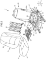
- a vehicle seat 1 includes, as main constituent elements, a head rest 2 for receiving the head of a seated occupant, a leg mechanism 3 for fixing the seat 1 to a passenger compartment floor, a seat cushion 4 for supporting a part (buttock) corresponding to the ischial bone of the seated occupant, and a seat back 5 for supporting a part (back) corresponding to the spine (backbone) of the seated occupant.
- the seat 1 includes, as a posture changing mechanism for adjusting a seated posture of the occupant, a lifter mechanism 6 capable of changing a height position of the seat cushion 4, a tilt mechanism 7 capable of changing a height position of a front end of the seat cushion 4, and a reclining mechanism 8 capable of changing a tilt angle of the seat back 5.
- the leg mechanism 3 is directly fixed to the passenger compartment floor.
- a member for substantially imparting cushion property is not disposed between the leg mechanism 3 and the floor.
- the leg mechanism 3 includes a sliding mechanism for slidably supporting the seat cushion 4 and the seat back 5 in a front-rear direction with respect to the floor.
- the sliding mechanism includes a pair of sliders 9 slidable along a pair of left and right slide rails, and is configured in such a way that the sliders 9 are lockable at a position desired by the occupant.
- the seat cushion 4 includes a metal frame member 10 for imparting a structural strength to the seat cushion 4, a metal elastic member 12, a polyurethane cushion member 13, and an outer cover member (not illustrated) for covering the elements 11 to 13.
- a metal frame member 10 for imparting a structural strength to the seat cushion 4
- a metal elastic member 12 for imparting a structural strength to the seat cushion 4
- a polyurethane cushion member 13 for covering the elements 11 to 13.
- an outer cover member (not illustrated) for covering the elements 11 to 13.
- illustration of the head rest 3 is omitted.
- the frame member 10 includes a pair of left and right side frames 11a and 11b extending in the front-rear direction, and a tilt pan 14 for connecting front ends of the side frames 11a and 11b to each other in a left-right direction (vehicle width direction).
- the side frame 11a is disposed to extend in the front-rear direction along a left portion of the seat cushion 4.
- the side frame 11b is disposed to extend in the front-rear direction along a right portion of the seat cushion 4.
- the left side frame 11a out of the paired side frames 11a and 11b corresponds to a "first side frame" in the present invention
- the right side frame 11b corresponds to a "second side frame” in the present invention.
- the paired side frames 11a and 11b are each a frame extending in the front-rear direction, and formed by performing press processing to a plate member.
- the specifications such as a material, a plate thickness, and a size are the same between the side frames 11a and 11b.
- the side frames 11a and 11b are different in a point whether reinforcement members R1 and R2 to be described later are present.
- each of the paired side frames 11a and 11b has a plurality of openings h1 to h6 passing through each side frame in the left-right direction (thickness direction).
- the opening h1 is formed in a front portion of each of the side frames 11a and 11b.
- the openings h1 are holes for fixing (fittingly receiving) both ends of a connecting member 15a extending in the left-right direction (vehicle width direction).
- the connecting member 15a connects front portions of the side frames 11a and 11b to each other in the left-right direction by being fixed to the side frames 11a and 11b at positions of the openings h1.
- the opening h2 is formed in a rear portion of each of the side frames 11a and 11b.
- the openings h2 are holes for fixing (fittingly receiving) both ends of a connecting member 15b extending in the left-right direction (vehicle width direction).
- the connecting member 15b connects rear portions of the side frames 11a and 11b to each other in the left-right direction by being fixed to the side frames 11a and 11b at positions of the openings h2.
- the opening h3 is formed near the middle of an upper portion of each of the side frames 11a and 11b in the front-rear direction.
- the openings h3 are holes for swingably supporting rear ends of left and right side portions (a pair of extension portions 14a and 14b to be described later) of the tilt pan 14 in an up-down direction.
- the opening h4 is formed in an upper rear portion of each of the side frames 11a and 11b, which is located on the upper front side of the opening h2.
- the opening h5 is formed in a rear end of each of the side frames 11a and 11b, which is located on the rear side of the opening h2.
- the openings h4 and h5 are holes for fixing brackets 16 that swingably support the seat back 5 in the front-rear direction.
- the opening h6 is formed near a front end of each of the side frames 11a and 11b, which is located on the front side of the opening h1.
- the openings h6 are holes for receiving both ends of a connecting member 44 extending in the left-right direction (vehicle width direction).
- the connecting member 44 is rotatably supported about front ends of the side frames 11a and 11b via the openings h6.
- reinforcement members R1 and R2 are provided on the right side frame 11b.
- the reinforcement members R1 and R2 partially reinforce the side frame 11b so as to suppress the right side frame 11b from displacing inward (to the left side), when the vehicle makes a turn.
- the reinforcement member R1 is disposed in a front area of the opening h1, specifically, an area from a front side to an upper side of the opening h1.
- the reinforcement member R1 is a metal plate member having a partially arc shape along the opening h1, and is fixedly mounted to an inner surface (left surface) of the right side frame 11b.
- the reinforcement member R2 is disposed in a front area of the opening h2, specifically, an area from a front side to an upper side of the opening h2.
- the reinforcement member R2 is a metal plate member having a partially arc shape along the opening h2, and is fixedly mounted to an inner surface (left surface) of the right side frame 11b.
- the reinforcement member R2 is disposed in an area from a position behind a line connecting a center of the opening h4 and a center of the opening h2 to a position proximal to a lower end of the opening h2. Since the opening h4 is a hole for fixing the support bracket 16 of the seat back 5, stress based on a load input from the seat back 5 to the side frames 11a and 11b is made maximum on a peripheral portion of the opening h4, when a load such as inertia force acting on an occupant is input to the seat back 5 during acceleration of the vehicle. In view of the above, it is preferable to dispose the reinforcement member R2 to be present within a predetermined radius (e.g. 75 mm) with respect to the opening h4 as a center, and align with a direction along which the side frame 11b is bent.
- a predetermined radius e.g. 75 mm
- the tilt pan 14 includes a body portion 14c for supporting a front end of the seat cushion 4, and a pair of extension portions 14a and 14b extending rearward from left and right ends of the body portion 14c. Rear ends of the extension portions 14a and 14b are pivotally supported on the side frames 11a and 11b at the openings h3. Specifically, the tilt pan 14 is swingably supported in the up-down direction about the openings h2 as pivot points.
- the elastic member 12 has a plurality of springs S made of metal wires.
- the elastic member 12 is mounted to be elastically deformable in the up-down direction at a position between the side frames 11a and 11b (inside the seat cushion 4) by fixation of front and rear ends of the elastic member 12 to the connecting members 15a and 15b.
- the elastic member 12 supports the buttock of the occupant from below, while elastically deforming downward.
- the cushion member 13 is supported by the frame member 10 and the elastic member 12, and is disposed to cover the frame member 10 and the elastic member 12.
- the cushion member 13 has elastic deformation characteristics (spring characteristics) and vibration damping characteristics. When the occupant is seated, the cushion member 13 supports the buttock of the occupant in cooperation with the elastic member 12, while causing compression deformation in the up-down direction. The cushion member 13 which has undergone compression deformation recovers to the original shape, as the occupant leaves the seat.
- the seat back 5 includes a metal frame member 20 (back frame) for imparting a structural strength to the seat back 5, a metal elastic member 22, a polyurethane cushion member 23, and an outer cover member (not illustrated) for covering the elements 21 to 23.
- a metal frame member 20 back frame
- a metal elastic member 22 for imparting a structural strength to the seat back 5
- a metal elastic member 22 for imparting a structural strength to the seat back 5
- a polyurethane cushion member 23 for covering the elements 21 to 23.
- the frame member 20 includes a pair of left and right vertical frames 21a and 21b extending in the up-down direction, and an inverted U-shaped upper frame 24 for connecting upper ends of the vertical frames 21a and 21b in the left-right direction (vehicle width direction).
- the paired vertical frames 21a and 21b are each a frame extending in the up-down direction, and formed by performing press processing to a plate member.
- the specifications such as a material, a plate thickness, and a size are the same between the vertical frames 21a and 21b.
- the vertical frames 21a and 21b are different in a point whether a reinforcement member R3 to be described later is present.
- a connecting member 25 extending in the left-right direction is provided on a lower end of the frame member 20. Both ends of the connecting member 25 pass through lower ends of the vertical frames 21a and 21b in a thickness direction (left-right direction), and are locked by the paired brackets 16 located on the outer side of the vertical frames 21a and 21b.
- the connecting member 25 having the above configuration functions as pivot points of the vertical frames 21a and 21b with respect to the paired brackets 16. Specifically, the vertical frames 21a and 21b are swingably supported to the paired brackets 16 via the connecting member 25.
- a gear part (a gear member 53 to be described later) of the reclining mechanism 8 is provided at a lower end of the left vertical frame 21a, and near a connecting portion between the lower end and the connecting member 25.
- a reinforcement member R3 is provided at a lower end of the right vertical frame 21b, and near a connecting portion between the lower end and the connecting member 25.
- the reinforcement member R3 is a metal plate member, and is fixedly mounted to an inner surface (left surface) of the right vertical frame 21b.
- the elastic member 22 is a mesh spring having a plurality of metal wires stretched in a net shape.
- the elastic member 22 is mounted to be elastically deformable in the front-rear direction inside the seat back 5 by fixation of a periphery of the elastic member 22 to the vertical frames 21a and 21b.
- the elastic member 22 supports the back of the occupant from behind, while causing elastic deformation in the front-rear direction.
- the cushion member 23 is supported by the frame member 20 and the elastic member 22, and is disposed to cover the frame member 20 and the elastic member 22.
- the cushion member 23 has elastic deformation characteristics (spring characteristics) and vibration damping characteristics. When the occupant is seated, the cushion member 23 supports the back of the occupant in cooperation with the elastic member 22, while causing compression deformation in the front-rear direction. The cushion member 23 which has undergone compression deformation recovers to the original shape, as the occupant leaves the seat.
- the seat 1 is configured in such a way that rigidity of a frame structure is sufficiently high, as compared with rigidity of a non-frame structure.
- the frame structure is a strength member constituting a framework of the seat 1, and includes the frame member 10 of the seat cushion 4, and the frame member 20 of the seat back 5.
- the non-frame structure is a portion formed by eliminating, from the seat 1, the strength member such as the frame members 10 and 20, and for example, includes the cushion member 13 and the elastic member 12 of the seat cushion 4, and the cushion member 23 and the elastic member 22 of the seat back 5.
- Rigidity of each of the frame structure and the non-frame structure can be expressed by a spring constant (N/mm).
- the spring constant is acquired by dividing a load acting on a structure by a displacement amount of the structure.
- a spring constant of the frame structure is set to be twenty times or more of a spring constant of the non-frame structure.
- a displacement amount of the frame structure is DF
- a displacement amount of the non-frame structure is DS in a case where a same load is applied to the frame structure and the non-frame structure
- a spring constant (N/mm) of the frame structure is set to be twenty times or more of a spring constant of the non-frame structure, a discrepancy between displacement characteristics of the seat 1, and displacement characteristics of the vehicle body is reduced.
- a spring constant of the frame structure it is desirable to set a spring constant of the frame structure to 70 N/mm or more in order to further improve traveling comfort.
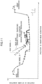
- a verification experiment by computer aided engineering (CAE) was performed in order to clarify an influence of a ratio between a spring constant of the frame structure and a spring constant of the non-frame structure on displacement characteristics of the seat 1.
- a seat model A in which a value (hereinafter, referred to as a rigidity ratio) acquired by dividing a spring constant (rigidity) of the frame structure by a spring constant (rigidity) of the non-frame structure was set to about 22, and a seat model B in which the rigidity ratio was set to about 19. Further, a displacement of each part of the vehicle during steady traveling in which an acceleration of 1G was generated, a displacement of each part of the seat model A at a time of occurrence of disturbance when the vehicle climbed over a slope, and a displacement of each part of the seat model B at a time of occurrence of disturbance when the vehicle climbed over a slope were acquired by analysis.
- a rigidity ratio a value acquired by dividing a spring constant (rigidity) of the frame structure by a spring constant (rigidity) of the non-frame structure was set to about 22
- a seat model B in which the rigidity ratio was set to about 19.
- the spring constant of the non-frame structure of the seat model A, and the spring constant of the non-frame structure of the seat model B were set to a same value (a spring constant of polyurethane), based on a premise that a material of the cushion member is polyurethane.
- FIG. 11 is a graph illustrating a result of the analysis.
- a horizontal axis indicates a coordinate in the front-rear direction
- a vertical axis indicates a coordinate in the up-down direction.
- the solid line graph indicates a position of each part of the vehicle during steady traveling in which an acceleration of 1G is generated.
- the solid line graphs annotated with "seat back (during steady traveling)", and “seat cushion (during steady traveling)" indicate positions of a seat back and a seat cushion, when the vehicle is steadily traveling.
- the dotted line graph annotated with "seat model A” indicates a position of the seat model A, when disturbance occurs (when the vehicle climbs over a slope) in a state that an occupant is seated on the seat.
- the broken line graph annotated with "seat model B” indicates a position of the seat model B, when disturbance occurs in a state that the occupant is seated.
- displacement characteristics of the seat model A at a time of occurrence of disturbance are similar to displacement characteristics (solid line) during steady traveling, as compared with displacement characteristics of the seat model B at a time of occurrence of disturbance.
- setting a rigidity ratio between the frame structure and the non-frame structure to 20 or more enables to provide an advantageous effect of making a behavior (displacement characteristics) of the seat close to a behavior of the vehicle body.
- posture changing mechanisms (the lifter mechanism 6, the tilt mechanism 7, and the reclining mechanism 8) of the seat 1 are described.
- the lifter mechanism 6 is a mechanism for raising or lowering the side frame 11a and 11b with respect to the floor (the sliders 9 of the sliding mechanism), while keeping the side frames 11a and 11b in a substantially horizontal state.
- the lifter mechanism 6 is manually operated in the present embodiment.
- the lifter mechanism 6 includes a lever-type operation portion 31 to be manually operated by an occupant, a pinion 31a (see FIG. 5 ) cooperatively connected to the operation portion 31, and a four-link mechanism operable by an operation of the operation portion 31.
- the operation portion 31 is pivotally supported on an outer surface (left surface) of the left side frame 11a.
- the pinion 31a is disposed on an inner surface (right surface) of the left side frame 11a, and is connected to the operation portion 31 via the side frame 11a.
- the pinion 31a is rotatable in response to an occupant's operation of the operation portion 31.
- the four-link mechanism includes the paired front and rear connecting members 15a and 15b, a pair of left and right front links 32a and 32b, and a pair of left and right rear links 33a and 33b.
- the paired front links 32a and 32b are each a link extending obliquely in the up-down direction, and is formed to be a substantially elliptical shape in a side view.
- a lower end of each of the front links 32a and 32b is pivotally supported on the slider 9.
- Each of left and right ends of the connecting member 15a passes through an upper end of each of the front links 32a and 32b.
- the right rear link 33b is a link extending obliquely in the up-down direction, and is formed to be a substantially elliptical shape in a side view.
- a lower end of the rear link 33b is pivotally supported on the slider 9.
- a right end of the connecting member 15b passes through an upper end of the rear link 33b.
- the left rear link 33a is a link having a substantially L-shape in a side view (see FIG. 5 ), and has a large size, as compared with the right rear link 33b.
- a lower end of the rear link 33a is pivotally supported on the slider 9.
- a left end of the connecting member 15b passes through an upper portion of the rear link 33a.
- a gear portion 35 engageable with the pinion 31a is formed on an upper front portion of the left rear link 33a.
- the rear link 33a disposed on an inner surface (right surface) of the left side frame 11a is larger than the rear link 33b disposed on an inner surface of the right side frame 11b; and the pinion 31a pivotally supported on the left side frame 11a, and the gear portion 35 of the rear link 33a are engaged with each other. Therefore, as far as the left and right side frames 11a and 11b have completely same specifications, apparent rigidity of the left side frame 11a is made larger than apparent rigidity of the right side frame 11b. In other words, in the present embodiment, rigidity of a left half portion of the seat cushion 4 including equipment such as the lifter mechanism 6 is likely to increase, as compared with rigidity of a right half portion of the seat cushion 4.
- the side frame 11b may be deformed so as to be inclined inward (leftward) due to a bending load acting on the side frame 11b.
- the reinforcement member R2 is provided near a front side of the opening h2 of the right side frame 11b.
- apparent rigidity of the left side frame 11a is made substantially equal to apparent rigidity of the right side frame 11b, and a phenomenon that the right side frame 11b is inclined as described above is suppressed.
- the tilt mechanism 7 is a mechanism for raising or lowering the tilt pan 14 with respect to the side frames 11a and 11b.
- the tilt mechanism 7 is manually operated in the present embodiment.
- the tilt mechanism 7 includes a lever-type operation portion 41 to be manually operated by an occupant, a pinion 41a (see FIG. 4 ) cooperatively connected to the operation portion 41, and a link mechanism operable by an operation of the operation portion 41.
- the operation portion 41 is pivotally supported on an outer surface (left surface) of the left side frame 11a.
- the pinion 41a is disposed on an inner surface (right surface) of the left side frame 11a, and is connected to the operation portion 41 via the side frame 11a.
- the pinion 41a is rotatable in response to an occupant's operation of the operation portion 41.
- the link mechanism includes the connecting member 44, a pair of left and right front links 42a and 42b, a pair of left and right rear links 43a and 43b, and a gear member 45.
- Rear ends of the rear links 43a and 43b are respectively fixed to both ends of the connecting member 44.
- the gear member 45 is pivotally supported on the left side frame 11a about the opening h1 (connecting member 15a) in the side frame 11a as a pivot point (see FIG. 10 ).
- a rear portion of the gear member 45 is engaged with the pinion 41a, and a front portion of the gear member 45 is engaged with a gear portion (not illustrated), which is formed on the rear link 43a.
- the tilt pan 14 When the operation portion 41 is operated in such a direction as to pivotally move the rear links 43a and 43b clockwise in a left side view, the tilt pan 14 is pivotally moved upward about the opening hole h3 as a pivot point. Conversely, when the operation portion 41 is operated in such a direction as to pivotally move the rear links 43a and 43b counterclockwise in a left side view, the tilt pan 14 is pivotally moved downward about the opening hole h3 as a pivot point.
- the gear member 45 is disposed on an inner surface (right surface) of the left side frame 11a, and the gear member 45 is engaged with the pinion 41a and the rear link 43a. Therefore, as far as the left and right side frames 11a and 11b have completely same specifications, apparent rigidity of the left side frame 11a is made larger than apparent rigidity of the right side frame 11b. In other words, in the present embodiment, rigidity of a left half portion of the seat cushion 4 including equipment such as the tilt mechanism 7 is likely to increase, as compared with rigidity of a right half portion of the seat cushion 4.
- the reinforcement member R1 is provided near a front side of the opening h1 of the right side frame 11b.
- the tilt mechanism 7 e.g. the gear member 45 of the tilt mechanism 7
- rigidity of a portion of the right side frame 11b corresponding to the tilt mechanism 7 is enhanced by the reinforcement member R1.
- apparent rigidity of the left side frame 11a and apparent rigidity of the right side frame 11b are made substantially equal to each other.
- the reclining mechanism 8 is a mechanism for adjusting a tilt angle of the seat back 5 (vertical frames 21a and 21b) with respect to the side frames 11a and 11b.
- the reclining mechanism 8 is manually operated in the present embodiment.
- the reclining mechanism 8 includes a lever-type operation portion 51 to be manually operated by an occupant, a gear member 52 operable by an operation of the operation portion 51, a gear member 53 engageable with the gear member 52, and an urging member 54 for urging the seat back 5 in such a direction as to pivotally move the seat back 5 forward about the connecting member 25.
- each of the operation portion 51, the gear member 52, and the urging member 54 is supported on the left bracket 16.
- the gear member 53 is fixed to a lower end of the left vertical frame 21a.
- the other end of the urging member 54 is locked by a lower end of the left vertical frame 21a.
- the gear member 53 is provided on a lower end of the left vertical frame 21a, and the gear member 53 is engaged with the gear member 52 supported on the left bracket 16. Therefore, as far as the left and right vertical frames 21a and 21b have completely same specifications, apparent rigidity of the left vertical frame 21a is made larger than apparent rigidity of the right vertical frame 21b. In other words, in the present embodiment, rigidity of a left half portion of the seat back 5 including equipment such as the reclining mechanism 8 is likely to increase, as compared with rigidity of a right half portion of the seat back 5.
- the reinforcement member R3 is provided on a lower end of the right vertical frame 21b, and at a position near a connecting portion between the lower end and the connecting member 25.
- the reinforcement member R3 rigidity of a portion of the right vertical frame 21b corresponding to the reclining mechanism 8 is enhanced by the reinforcement member R3.
- apparent rigidity of the left vertical frame 21a and apparent rigidity of the right vertical frame 21b are made substantially equal to each other.
- an experiment by computer aided engineering was performed.
- a load of 100 N along the vehicle width direction was input to a position equivalent to the opening h4 in the right side frame 11b of each of the models, and a displacement amount at a position near an upper side of the opening h5 was calculated.
- FIG. 7 illustrates a result of the analysis.
- a displacement amount of the right side frame 11b is large, as compared with a displacement amount of the left side frame 11a, and an inclination phenomenon occurs in the right side frame 11b.
- rigidity of the left side frame 11a is enhanced by the presence of a posture changing mechanism including the lifter mechanism 6 and the tilt mechanism 7.
- a displacement amount of the left side frame 11a is substantially equal to a displacement amount of the right side frame 11b. This is conceivably because of the operations of the reinforcement members R1 and R2 provided on the right side frame 11b.
- the lifter mechanism 6 and the tilt mechanism 7 (posture changing mechanisms) capable of changing a posture of the seat cushion 4 are provided only on the left side frame 11a, it is possible to secure comfort of an occupant by appropriately adjusting a seated posture of the occupant, while reducing the weight of the seat 1 including the lifter mechanism 6 and the tilt mechanism 7.
- the reinforcement members R1 and R2 are provided at portions of the right side frame 11b where the reinforcement members R1 and R2 overlap the lifter mechanism 6 and the tilt mechanism 7 in a side view, it is possible to reduce a rigidity difference between left and right portions of the seat cushion 4 including equipment such as the lifter mechanism 6 and the tilt mechanism 7, in other words, a difference between rigidity of a left half portion of the seat cushion 4 where both of the mechanisms 6 and 7 are provided, and rigidity of a right half portion of the seat cushion 4 where the mechanisms 6 and 7 are not provided. Thus, it is possible to suppress displacement of the seat 1 resulting from the rigidity difference.
- the reinforcement members R1 and R2 are provided on the right side frame 11b on which the lifter mechanism 6 and the tilt mechanism 7 are not mounted. This enables to advantageously reduce the rigidity difference, while securing a posture adjustment function by the lifter mechanism 6 and the tilt mechanism 7.
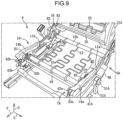
- FIGS. 8 to 10 members similar to those in the first embodiment are indicated with the same reference numbers, and detailed description thereof is omitted.
- the lifter mechanism 6A includes an operation portion 31A to be operated by an occupant, the motor M1 to be driven in response to an operation of the operation portion 31A, a pinion 31a, and a 4-link mechanism.
- the motor M1 is disposed on an outer surface (left surface) of the left side frame 11a, and is able to drive and rotate the pinion 31a.
- the tilt mechanism 7A includes an operation portion 41A to be operated by an occupant, the motor M2 to be driven in response to an operation of the operation portion 41A, a pinion 41a, and a link mechanism.
- the motor M2 is disposed on an inner surface (right surface) of the left side frame 11a, and is able to drive and rotate the pinion 41a.
- the reclining mechanism 8A includes an operation portion 51A to be operated by an occupant, the motor M3 to be driven in response to an operation of the operation portion 51A, and gear members 52 and 53 engaged with each other.
- the motor M3 is disposed on an inner surface (right surface) of a left vertical frame 21a, and is able to drive and rotate the gear member 52.
- reinforcement members R1 to R3 are provided on a side frame 11b on a side (right side) opposite to a left side frame 11a on which the posture changing mechanisms (the lifter mechanism 6A, the tilt mechanism 7A, and the reclining mechanism 8A) are provided.
- the electrically operated posture changing mechanisms (6A to 8A) having the motors M1 to M3 as drive sources are provided on one side potion of the seat 1A
- the reinforcement members R1 to R3 are provided on a frame on a side opposite to the posture changing mechanisms. Therefore, it is possible to reduce, by the reinforcement members R1 to R3, a rigidity difference between left and right portions of the seat 1A due to the presence of the posture changing mechanisms including the motors M1 to M3.
- a seat structure is applied to a vehicle seat provided with a seat cushion and a seat back.
- the seat structure includes: a first side frame extending in a front-rear direction along one side portion of the seat cushion; a second side frame extending in the front-rear direction along the other side portion of the seat cushion; a posture changing mechanism mounted on the first side frame, and capable of changing a posture of the seat cushion; and a reinforcement member provided at a portion of the second side frame where the reinforcement member overlaps the posture changing mechanism in a side view.
- the vehicle seat structure it is possible to appropriately adjust a seated posture of an occupant by the posture changing mechanism mounted on the first side frame of the seat cushion, and secure occupant's comfort.
- the reinforcement member is provided at a portion of the second side frame where the reinforcement member overlaps the posture changing mechanism in a side view, it is possible to reduce a rigidity difference between left and right portions of the seat cushion including equipment such as the posture changing mechanism, namely, a difference between rigidity of one of a left half portion and a right half portion of the seat cushion including the posture changing mechanism, and rigidity of the other thereof. Thus, it is possible to suppress displacement of the seat resulting from the rigidity difference.
- the posture changing mechanism may include at least one of a lifter mechanism for raising or lowering the seat cushion, while keeping the seat cushion in a substantially horizontal state, and a tilt mechanism for raising or lowering a front end of the seat cushion.
- the posture changing mechanism may be an electrically operated mechanism including an electric motor as a drive source.
Landscapes
- Engineering & Computer Science (AREA)
- Aviation & Aerospace Engineering (AREA)
- Transportation (AREA)
- Mechanical Engineering (AREA)
- Seats For Vehicles (AREA)
Claims (4)
- Fahrzeugsitzstruktur, die mit einem Sitzkissen (4) und einer Sitzlehne (5) vorgesehen ist, aufweisend:einen ersten Seitenrahmen (11a), der sich in einer Vorwärts-Rückwärts-Richtung entlang eines Seitenabschnitts des Sitzkissens (4) erstreckt;einen zweiten Seitenrahmen (11b), der sich in der Vorwärts-Rückwärts-Richtung entlang des anderen Seitenabschnitts des Sitzkissens (4) erstreckt;einen Haltungsänderungsmechanismus (6, 7), der in der Lage ist, eine Haltung des Sitzkissens (4) zu ändern;ein Verstärkungselement (R1, R2), das den Haltungsänderungsmechanismus (6, 7) in einer Seitenansicht überlappt;dadurch gekennzeichnet, dassder Haltungsänderungsmechanismus (6, 7) nur an dem ersten Seitenrahmen (11a) angebracht ist, wohingegen das Verstärkungselement (R1, R2) an einem Abschnitt nur des zweiten Seitenrahmens (11b) vorgesehen ist.
- Fahrzeugsitzstruktur nach Anspruch 1, wobei
das Verstärkungselement (R1, R2) eine Funktion aufweist, die verhindern soll, dass sich der zweite Seitenrahmen (11b) in Richtung des ersten Seitenrahmens (11a) bewegt. - Fahrzeugsitzstruktur nach Anspruch 1 oder 2, wobei
der Haltungsänderungsmechanismus einen Hebemechanismus (6) zum Anheben oder Absenken des Sitzkissens (4), während das Sitzkissen (4) in einem im Wesentlichen horizontalen Zustand gehalten wird, und/oder einen Neigungsmechanismus (7) zum Anheben oder Absenken eines vorderen Endes des Sitzkissens (4) aufweist. - Fahrzeugsitzstruktur nach einem der Ansprüche 1 bis 3, wobei
der Haltungsänderungsmechanismus ein elektrisch betätigter Mechanismus (6A, 7A) mit einem Elektromotor (M1, M2) als Antriebsquelle ist.
Applications Claiming Priority (2)
| Application Number | Priority Date | Filing Date | Title |
|---|---|---|---|
| JP2018061269A JP6604491B2 (ja) | 2018-03-28 | 2018-03-28 | 車両用シート構造 |
| PCT/JP2019/007887 WO2019187959A1 (ja) | 2018-03-28 | 2019-02-28 | 車両用シート構造 |
Publications (3)
| Publication Number | Publication Date |
|---|---|
| EP3712008A1 EP3712008A1 (de) | 2020-09-23 |
| EP3712008A4 EP3712008A4 (de) | 2020-12-30 |
| EP3712008B1 true EP3712008B1 (de) | 2024-07-17 |
Family
ID=68061201
Family Applications (1)
| Application Number | Title | Priority Date | Filing Date |
|---|---|---|---|
| EP19777243.7A Active EP3712008B1 (de) | 2018-03-28 | 2019-02-28 | Fahrzeugsitzstruktur |
Country Status (5)
| Country | Link |
|---|---|
| US (1) | US11052790B2 (de) |
| EP (1) | EP3712008B1 (de) |
| JP (1) | JP6604491B2 (de) |
| CN (1) | CN111867880B (de) |
| WO (1) | WO2019187959A1 (de) |
Families Citing this family (3)
| Publication number | Priority date | Publication date | Assignee | Title |
|---|---|---|---|---|
| JP7484346B2 (ja) | 2020-04-01 | 2024-05-16 | マツダ株式会社 | 運転姿勢設定用シート制御装置および該方法 |
| FR3122128B1 (fr) * | 2021-04-22 | 2025-03-07 | Faurecia Sieges Dautomobile | Dossier de siège de véhicule intégrant au moins un dispositif vibrant |
| JP7729072B2 (ja) | 2021-06-02 | 2025-08-26 | マツダ株式会社 | 運転姿勢設定装置および該方法 |
Family Cites Families (18)
| Publication number | Priority date | Publication date | Assignee | Title |
|---|---|---|---|---|
| JP2001149175A (ja) | 1999-11-29 | 2001-06-05 | Tachi S Co Ltd | シートバックフレーム構造 |
| JP5381300B2 (ja) | 2009-05-07 | 2014-01-08 | トヨタ紡織株式会社 | 車両用シート |
| JP5599625B2 (ja) * | 2010-02-26 | 2014-10-01 | テイ・エス テック株式会社 | 車両用シート |
| JP2012071005A (ja) * | 2010-09-29 | 2012-04-12 | Ts Tech Co Ltd | シートバックフレーム |
| JP5412420B2 (ja) * | 2010-12-24 | 2014-02-12 | 本田技研工業株式会社 | 車両用シート |
| JP5741414B2 (ja) * | 2011-12-06 | 2015-07-01 | トヨタ紡織株式会社 | 車両用シートのシートフレーム補強構造 |
| EP2894061B1 (de) | 2012-09-03 | 2019-11-06 | TS Tech Co., Ltd. | Sitzrahmen für einen fahrzeugsitz |
| US9744884B2 (en) | 2012-09-21 | 2017-08-29 | Ts Tech Co., Ltd | Vehicle seat having an elevation mechanism and a cushion frame with rigid portions |
| JP2014100992A (ja) * | 2012-11-19 | 2014-06-05 | Ts Tech Co Ltd | シート装置 |
| JP6278443B2 (ja) * | 2013-11-08 | 2018-02-14 | テイ・エス テック株式会社 | シートバックフレームの補強構造 |
| US10214120B2 (en) * | 2014-03-25 | 2019-02-26 | Cvg Management Corporation | Seat tilt control mechanism |
| JP6297409B2 (ja) | 2014-05-20 | 2018-03-20 | 株式会社デルタツーリング | 座席構造 |
| JP6324811B2 (ja) * | 2014-05-26 | 2018-05-16 | トヨタ紡織株式会社 | 乗物用シート |
| JP2016005922A (ja) * | 2014-06-20 | 2016-01-14 | テイ・エス テック株式会社 | 座部のフレーム |
| JP6468070B2 (ja) * | 2015-05-22 | 2019-02-13 | トヨタ紡織株式会社 | 乗物用シート |
| CN108025664A (zh) | 2015-10-02 | 2018-05-11 | 提爱思科技股份有限公司 | 座椅框架 |
| JP6224045B2 (ja) * | 2015-10-02 | 2017-11-01 | テイ・エス テック株式会社 | シートフレーム |
| JP7111446B2 (ja) * | 2017-01-24 | 2022-08-02 | トヨタ紡織株式会社 | 乗物用シートフレーム |
-
2018
- 2018-03-28 JP JP2018061269A patent/JP6604491B2/ja active Active
-
2019
- 2019-02-28 EP EP19777243.7A patent/EP3712008B1/de active Active
- 2019-02-28 US US16/955,006 patent/US11052790B2/en active Active
- 2019-02-28 CN CN201980006571.7A patent/CN111867880B/zh active Active
- 2019-02-28 WO PCT/JP2019/007887 patent/WO2019187959A1/ja not_active Ceased
Also Published As
| Publication number | Publication date |
|---|---|
| WO2019187959A1 (ja) | 2019-10-03 |
| US20200384895A1 (en) | 2020-12-10 |
| JP6604491B2 (ja) | 2019-11-13 |
| US11052790B2 (en) | 2021-07-06 |
| CN111867880A (zh) | 2020-10-30 |
| JP2019172016A (ja) | 2019-10-10 |
| EP3712008A4 (de) | 2020-12-30 |
| CN111867880B (zh) | 2022-08-26 |
| EP3712008A1 (de) | 2020-09-23 |
Similar Documents
| Publication | Publication Date | Title |
|---|---|---|
| US11046219B2 (en) | Method for assembling vehicle seat with cushion plate | |
| JP7106988B2 (ja) | ヘッドレスト及び車両用シート | |
| US20200139862A1 (en) | Vehicle seat | |
| US9493095B2 (en) | Seat | |
| EP3712008B1 (de) | Fahrzeugsitzstruktur | |
| JP7851374B2 (ja) | 乗物用シート | |
| JP5852326B2 (ja) | 車両用シート | |
| JP2019123435A (ja) | 車両用シート構造 | |
| JP4794456B2 (ja) | 自動車用の調節可能なシート及び同シートが設けられた自動車 | |
| JPH05111415A (ja) | シートフレーム取付構造 | |
| JP2001026232A (ja) | 車両用シート装置 | |
| JP2020175710A (ja) | 車両用シート | |
| CN110944872B (zh) | 车辆用座椅及其设计方法 | |
| KR20250014327A (ko) | 모빌리티용 시트 조절 장치 | |
| CN113135132B (zh) | 车载座椅装置 | |
| JP3452285B2 (ja) | 車輛用リヤシート | |
| JPH09202167A (ja) | サスペンションシート | |
| JP5088528B2 (ja) | リクライニング式自動車用シート | |
| US20070108811A1 (en) | Seat for a motor vehicle, and motor vehicle equipped with this seat | |
| JP4492372B2 (ja) | 自動車の着座姿勢調整装置 | |
| JP7772607B2 (ja) | 車両用シートフレーム及び車両用シート | |
| JP6777495B2 (ja) | 車両用シート | |
| JP6064922B2 (ja) | 車両用シート装置 | |
| KR101034306B1 (ko) | 자동차의 리어파워시트 | |
| JP2014151771A (ja) | 座席構造 |
Legal Events
| Date | Code | Title | Description |
|---|---|---|---|
| STAA | Information on the status of an ep patent application or granted ep patent |
Free format text: STATUS: THE INTERNATIONAL PUBLICATION HAS BEEN MADE |
|
| PUAI | Public reference made under article 153(3) epc to a published international application that has entered the european phase |
Free format text: ORIGINAL CODE: 0009012 |
|
| STAA | Information on the status of an ep patent application or granted ep patent |
Free format text: STATUS: REQUEST FOR EXAMINATION WAS MADE |
|
| 17P | Request for examination filed |
Effective date: 20200615 |
|
| AK | Designated contracting states |
Kind code of ref document: A1 Designated state(s): AL AT BE BG CH CY CZ DE DK EE ES FI FR GB GR HR HU IE IS IT LI LT LU LV MC MK MT NL NO PL PT RO RS SE SI SK SM TR |
|
| AX | Request for extension of the european patent |
Extension state: BA ME |
|
| RIN1 | Information on inventor provided before grant (corrected) |
Inventor name: SUZUKI, TAKASHI Inventor name: SAKAI, SHIN Inventor name: KOBAYASHI, SHIGERU Inventor name: IWAKURA, HIROYUKI Inventor name: NONOWAKI, KOJI |
|
| A4 | Supplementary search report drawn up and despatched |
Effective date: 20201127 |
|
| RIC1 | Information provided on ipc code assigned before grant |
Ipc: B60N 2/16 20060101ALI20201123BHEP Ipc: B60N 2/90 20180101ALI20201123BHEP Ipc: B60N 2/22 20060101ALI20201123BHEP Ipc: B60N 2/02 20060101AFI20201123BHEP |
|
| DAV | Request for validation of the european patent (deleted) | ||
| DAX | Request for extension of the european patent (deleted) | ||
| GRAP | Despatch of communication of intention to grant a patent |
Free format text: ORIGINAL CODE: EPIDOSNIGR1 |
|
| STAA | Information on the status of an ep patent application or granted ep patent |
Free format text: STATUS: GRANT OF PATENT IS INTENDED |
|
| INTG | Intention to grant announced |
Effective date: 20240322 |
|
| GRAS | Grant fee paid |
Free format text: ORIGINAL CODE: EPIDOSNIGR3 |
|
| GRAA | (expected) grant |
Free format text: ORIGINAL CODE: 0009210 |
|
| STAA | Information on the status of an ep patent application or granted ep patent |
Free format text: STATUS: THE PATENT HAS BEEN GRANTED |
|
| AK | Designated contracting states |
Kind code of ref document: B1 Designated state(s): AL AT BE BG CH CY CZ DE DK EE ES FI FR GB GR HR HU IE IS IT LI LT LU LV MC MK MT NL NO PL PT RO RS SE SI SK SM TR |
|
| REG | Reference to a national code |
Ref country code: CH Ref legal event code: EP |
|
| REG | Reference to a national code |
Ref country code: DE Ref legal event code: R096 Ref document number: 602019055395 Country of ref document: DE |
|
| REG | Reference to a national code |
Ref country code: IE Ref legal event code: FG4D |
|
| REG | Reference to a national code |
Ref country code: LT Ref legal event code: MG9D |
|
| REG | Reference to a national code |
Ref country code: NL Ref legal event code: MP Effective date: 20240717 |
|
| PG25 | Lapsed in a contracting state [announced via postgrant information from national office to epo] |
Ref country code: PT Free format text: LAPSE BECAUSE OF FAILURE TO SUBMIT A TRANSLATION OF THE DESCRIPTION OR TO PAY THE FEE WITHIN THE PRESCRIBED TIME-LIMIT Effective date: 20241118 |
|
| REG | Reference to a national code |
Ref country code: AT Ref legal event code: MK05 Ref document number: 1703812 Country of ref document: AT Kind code of ref document: T Effective date: 20240717 |
|
| PG25 | Lapsed in a contracting state [announced via postgrant information from national office to epo] |
Ref country code: NL Free format text: LAPSE BECAUSE OF FAILURE TO SUBMIT A TRANSLATION OF THE DESCRIPTION OR TO PAY THE FEE WITHIN THE PRESCRIBED TIME-LIMIT Effective date: 20240717 |
|
| PG25 | Lapsed in a contracting state [announced via postgrant information from national office to epo] |
Ref country code: PT Free format text: LAPSE BECAUSE OF FAILURE TO SUBMIT A TRANSLATION OF THE DESCRIPTION OR TO PAY THE FEE WITHIN THE PRESCRIBED TIME-LIMIT Effective date: 20241118 Ref country code: NL Free format text: LAPSE BECAUSE OF FAILURE TO SUBMIT A TRANSLATION OF THE DESCRIPTION OR TO PAY THE FEE WITHIN THE PRESCRIBED TIME-LIMIT Effective date: 20240717 |
|
| PG25 | Lapsed in a contracting state [announced via postgrant information from national office to epo] |
Ref country code: NO Free format text: LAPSE BECAUSE OF FAILURE TO SUBMIT A TRANSLATION OF THE DESCRIPTION OR TO PAY THE FEE WITHIN THE PRESCRIBED TIME-LIMIT Effective date: 20241017 |
|
| PG25 | Lapsed in a contracting state [announced via postgrant information from national office to epo] |
Ref country code: GR Free format text: LAPSE BECAUSE OF FAILURE TO SUBMIT A TRANSLATION OF THE DESCRIPTION OR TO PAY THE FEE WITHIN THE PRESCRIBED TIME-LIMIT Effective date: 20241018 Ref country code: FI Free format text: LAPSE BECAUSE OF FAILURE TO SUBMIT A TRANSLATION OF THE DESCRIPTION OR TO PAY THE FEE WITHIN THE PRESCRIBED TIME-LIMIT Effective date: 20240717 Ref country code: PL Free format text: LAPSE BECAUSE OF FAILURE TO SUBMIT A TRANSLATION OF THE DESCRIPTION OR TO PAY THE FEE WITHIN THE PRESCRIBED TIME-LIMIT Effective date: 20240717 |
|
| PG25 | Lapsed in a contracting state [announced via postgrant information from national office to epo] |
Ref country code: BG Free format text: LAPSE BECAUSE OF FAILURE TO SUBMIT A TRANSLATION OF THE DESCRIPTION OR TO PAY THE FEE WITHIN THE PRESCRIBED TIME-LIMIT Effective date: 20240717 |
|
| PG25 | Lapsed in a contracting state [announced via postgrant information from national office to epo] |
Ref country code: LV Free format text: LAPSE BECAUSE OF FAILURE TO SUBMIT A TRANSLATION OF THE DESCRIPTION OR TO PAY THE FEE WITHIN THE PRESCRIBED TIME-LIMIT Effective date: 20240717 |
|
| PG25 | Lapsed in a contracting state [announced via postgrant information from national office to epo] |
Ref country code: AT Free format text: LAPSE BECAUSE OF FAILURE TO SUBMIT A TRANSLATION OF THE DESCRIPTION OR TO PAY THE FEE WITHIN THE PRESCRIBED TIME-LIMIT Effective date: 20240717 Ref country code: IS Free format text: LAPSE BECAUSE OF FAILURE TO SUBMIT A TRANSLATION OF THE DESCRIPTION OR TO PAY THE FEE WITHIN THE PRESCRIBED TIME-LIMIT Effective date: 20241117 |
|
| PG25 | Lapsed in a contracting state [announced via postgrant information from national office to epo] |
Ref country code: HR Free format text: LAPSE BECAUSE OF FAILURE TO SUBMIT A TRANSLATION OF THE DESCRIPTION OR TO PAY THE FEE WITHIN THE PRESCRIBED TIME-LIMIT Effective date: 20240717 |
|
| PG25 | Lapsed in a contracting state [announced via postgrant information from national office to epo] |
Ref country code: RS Free format text: LAPSE BECAUSE OF FAILURE TO SUBMIT A TRANSLATION OF THE DESCRIPTION OR TO PAY THE FEE WITHIN THE PRESCRIBED TIME-LIMIT Effective date: 20241017 Ref country code: ES Free format text: LAPSE BECAUSE OF FAILURE TO SUBMIT A TRANSLATION OF THE DESCRIPTION OR TO PAY THE FEE WITHIN THE PRESCRIBED TIME-LIMIT Effective date: 20240717 |
|
| PG25 | Lapsed in a contracting state [announced via postgrant information from national office to epo] |
Ref country code: RS Free format text: LAPSE BECAUSE OF FAILURE TO SUBMIT A TRANSLATION OF THE DESCRIPTION OR TO PAY THE FEE WITHIN THE PRESCRIBED TIME-LIMIT Effective date: 20241017 Ref country code: PL Free format text: LAPSE BECAUSE OF FAILURE TO SUBMIT A TRANSLATION OF THE DESCRIPTION OR TO PAY THE FEE WITHIN THE PRESCRIBED TIME-LIMIT Effective date: 20240717 Ref country code: NO Free format text: LAPSE BECAUSE OF FAILURE TO SUBMIT A TRANSLATION OF THE DESCRIPTION OR TO PAY THE FEE WITHIN THE PRESCRIBED TIME-LIMIT Effective date: 20241017 Ref country code: LV Free format text: LAPSE BECAUSE OF FAILURE TO SUBMIT A TRANSLATION OF THE DESCRIPTION OR TO PAY THE FEE WITHIN THE PRESCRIBED TIME-LIMIT Effective date: 20240717 Ref country code: IS Free format text: LAPSE BECAUSE OF FAILURE TO SUBMIT A TRANSLATION OF THE DESCRIPTION OR TO PAY THE FEE WITHIN THE PRESCRIBED TIME-LIMIT Effective date: 20241117 Ref country code: HR Free format text: LAPSE BECAUSE OF FAILURE TO SUBMIT A TRANSLATION OF THE DESCRIPTION OR TO PAY THE FEE WITHIN THE PRESCRIBED TIME-LIMIT Effective date: 20240717 Ref country code: GR Free format text: LAPSE BECAUSE OF FAILURE TO SUBMIT A TRANSLATION OF THE DESCRIPTION OR TO PAY THE FEE WITHIN THE PRESCRIBED TIME-LIMIT Effective date: 20241018 Ref country code: FI Free format text: LAPSE BECAUSE OF FAILURE TO SUBMIT A TRANSLATION OF THE DESCRIPTION OR TO PAY THE FEE WITHIN THE PRESCRIBED TIME-LIMIT Effective date: 20240717 Ref country code: ES Free format text: LAPSE BECAUSE OF FAILURE TO SUBMIT A TRANSLATION OF THE DESCRIPTION OR TO PAY THE FEE WITHIN THE PRESCRIBED TIME-LIMIT Effective date: 20240717 Ref country code: BG Free format text: LAPSE BECAUSE OF FAILURE TO SUBMIT A TRANSLATION OF THE DESCRIPTION OR TO PAY THE FEE WITHIN THE PRESCRIBED TIME-LIMIT Effective date: 20240717 Ref country code: AT Free format text: LAPSE BECAUSE OF FAILURE TO SUBMIT A TRANSLATION OF THE DESCRIPTION OR TO PAY THE FEE WITHIN THE PRESCRIBED TIME-LIMIT Effective date: 20240717 |
|
| PG25 | Lapsed in a contracting state [announced via postgrant information from national office to epo] |
Ref country code: DK Free format text: LAPSE BECAUSE OF FAILURE TO SUBMIT A TRANSLATION OF THE DESCRIPTION OR TO PAY THE FEE WITHIN THE PRESCRIBED TIME-LIMIT Effective date: 20240717 Ref country code: SM Free format text: LAPSE BECAUSE OF FAILURE TO SUBMIT A TRANSLATION OF THE DESCRIPTION OR TO PAY THE FEE WITHIN THE PRESCRIBED TIME-LIMIT Effective date: 20240717 Ref country code: RO Free format text: LAPSE BECAUSE OF FAILURE TO SUBMIT A TRANSLATION OF THE DESCRIPTION OR TO PAY THE FEE WITHIN THE PRESCRIBED TIME-LIMIT Effective date: 20240717 |
|
| REG | Reference to a national code |
Ref country code: DE Ref legal event code: R097 Ref document number: 602019055395 Country of ref document: DE |
|
| PG25 | Lapsed in a contracting state [announced via postgrant information from national office to epo] |
Ref country code: EE Free format text: LAPSE BECAUSE OF FAILURE TO SUBMIT A TRANSLATION OF THE DESCRIPTION OR TO PAY THE FEE WITHIN THE PRESCRIBED TIME-LIMIT Effective date: 20240717 |
|
| PG25 | Lapsed in a contracting state [announced via postgrant information from national office to epo] |
Ref country code: CZ Free format text: LAPSE BECAUSE OF FAILURE TO SUBMIT A TRANSLATION OF THE DESCRIPTION OR TO PAY THE FEE WITHIN THE PRESCRIBED TIME-LIMIT Effective date: 20240717 |
|
| PG25 | Lapsed in a contracting state [announced via postgrant information from national office to epo] |
Ref country code: SK Free format text: LAPSE BECAUSE OF FAILURE TO SUBMIT A TRANSLATION OF THE DESCRIPTION OR TO PAY THE FEE WITHIN THE PRESCRIBED TIME-LIMIT Effective date: 20240717 |
|
| PLBE | No opposition filed within time limit |
Free format text: ORIGINAL CODE: 0009261 |
|
| STAA | Information on the status of an ep patent application or granted ep patent |
Free format text: STATUS: NO OPPOSITION FILED WITHIN TIME LIMIT |
|
| 26N | No opposition filed |
Effective date: 20250422 |
|
| PG25 | Lapsed in a contracting state [announced via postgrant information from national office to epo] |
Ref country code: SE Free format text: LAPSE BECAUSE OF FAILURE TO SUBMIT A TRANSLATION OF THE DESCRIPTION OR TO PAY THE FEE WITHIN THE PRESCRIBED TIME-LIMIT Effective date: 20240717 |
|
| PG25 | Lapsed in a contracting state [announced via postgrant information from national office to epo] |
Ref country code: MC Free format text: LAPSE BECAUSE OF FAILURE TO SUBMIT A TRANSLATION OF THE DESCRIPTION OR TO PAY THE FEE WITHIN THE PRESCRIBED TIME-LIMIT Effective date: 20240717 |
|
| REG | Reference to a national code |
Ref country code: CH Ref legal event code: PL |
|
| PG25 | Lapsed in a contracting state [announced via postgrant information from national office to epo] |
Ref country code: LU Free format text: LAPSE BECAUSE OF NON-PAYMENT OF DUE FEES Effective date: 20250228 |
|
| PG25 | Lapsed in a contracting state [announced via postgrant information from national office to epo] |
Ref country code: CH Free format text: LAPSE BECAUSE OF NON-PAYMENT OF DUE FEES Effective date: 20250228 |
|
| GBPC | Gb: european patent ceased through non-payment of renewal fee |
Effective date: 20250228 |
|
| REG | Reference to a national code |
Ref country code: BE Ref legal event code: MM Effective date: 20250228 |
|
| PG25 | Lapsed in a contracting state [announced via postgrant information from national office to epo] |
Ref country code: GB Free format text: LAPSE BECAUSE OF NON-PAYMENT OF DUE FEES Effective date: 20250228 |
|
| PG25 | Lapsed in a contracting state [announced via postgrant information from national office to epo] |
Ref country code: FR Free format text: LAPSE BECAUSE OF NON-PAYMENT OF DUE FEES Effective date: 20250228 |
|
| PG25 | Lapsed in a contracting state [announced via postgrant information from national office to epo] |
Ref country code: BE Free format text: LAPSE BECAUSE OF NON-PAYMENT OF DUE FEES Effective date: 20250228 |
|
| PG25 | Lapsed in a contracting state [announced via postgrant information from national office to epo] |
Ref country code: IE Free format text: LAPSE BECAUSE OF NON-PAYMENT OF DUE FEES Effective date: 20250228 |
|
| PG25 | Lapsed in a contracting state [announced via postgrant information from national office to epo] |
Ref country code: IT Free format text: LAPSE BECAUSE OF FAILURE TO SUBMIT A TRANSLATION OF THE DESCRIPTION OR TO PAY THE FEE WITHIN THE PRESCRIBED TIME-LIMIT Effective date: 20240717 |
|
| PGFP | Annual fee paid to national office [announced via postgrant information from national office to epo] |
Ref country code: DE Payment date: 20260102 Year of fee payment: 8 |