EP3705591B1 - Lochdorn und herstellungsverfahren dafür - Google Patents
Lochdorn und herstellungsverfahren dafür Download PDFInfo
- Publication number
- EP3705591B1 EP3705591B1 EP18874192.0A EP18874192A EP3705591B1 EP 3705591 B1 EP3705591 B1 EP 3705591B1 EP 18874192 A EP18874192 A EP 18874192A EP 3705591 B1 EP3705591 B1 EP 3705591B1
- Authority
- EP
- European Patent Office
- Prior art keywords
- plug
- tip portion
- piercer
- protective layer
- piercer plug
- Prior art date
- Legal status (The legal status is an assumption and is not a legal conclusion. Google has not performed a legal analysis and makes no representation as to the accuracy of the status listed.)
- Active
Links
Images


Classifications
-
- C—CHEMISTRY; METALLURGY
- C22—METALLURGY; FERROUS OR NON-FERROUS ALLOYS; TREATMENT OF ALLOYS OR NON-FERROUS METALS
- C22C—ALLOYS
- C22C38/00—Ferrous alloys, e.g. steel alloys
- C22C38/02—Ferrous alloys, e.g. steel alloys containing silicon
-
- C—CHEMISTRY; METALLURGY
- C21—METALLURGY OF IRON
- C21D—MODIFYING THE PHYSICAL STRUCTURE OF FERROUS METALS; GENERAL DEVICES FOR HEAT TREATMENT OF FERROUS OR NON-FERROUS METALS OR ALLOYS; MAKING METAL MALLEABLE, e.g. BY DECARBURISATION OR TEMPERING
- C21D1/00—General methods or devices for heat treatment, e.g. annealing, hardening, quenching or tempering
- C21D1/18—Hardening; Quenching with or without subsequent tempering
-
- C—CHEMISTRY; METALLURGY
- C21—METALLURGY OF IRON
- C21D—MODIFYING THE PHYSICAL STRUCTURE OF FERROUS METALS; GENERAL DEVICES FOR HEAT TREATMENT OF FERROUS OR NON-FERROUS METALS OR ALLOYS; MAKING METAL MALLEABLE, e.g. BY DECARBURISATION OR TEMPERING
- C21D6/00—Heat treatment of ferrous alloys
- C21D6/004—Heat treatment of ferrous alloys containing Cr and Ni
-
- C—CHEMISTRY; METALLURGY
- C21—METALLURGY OF IRON
- C21D—MODIFYING THE PHYSICAL STRUCTURE OF FERROUS METALS; GENERAL DEVICES FOR HEAT TREATMENT OF FERROUS OR NON-FERROUS METALS OR ALLOYS; MAKING METAL MALLEABLE, e.g. BY DECARBURISATION OR TEMPERING
- C21D6/00—Heat treatment of ferrous alloys
- C21D6/005—Heat treatment of ferrous alloys containing Mn
-
- C—CHEMISTRY; METALLURGY
- C21—METALLURGY OF IRON
- C21D—MODIFYING THE PHYSICAL STRUCTURE OF FERROUS METALS; GENERAL DEVICES FOR HEAT TREATMENT OF FERROUS OR NON-FERROUS METALS OR ALLOYS; MAKING METAL MALLEABLE, e.g. BY DECARBURISATION OR TEMPERING
- C21D9/00—Heat treatment, e.g. annealing, hardening, quenching or tempering, adapted for particular articles; Furnaces therefor
- C21D9/0068—Heat treatment, e.g. annealing, hardening, quenching or tempering, adapted for particular articles; Furnaces therefor for particular articles not mentioned below
-
- C—CHEMISTRY; METALLURGY
- C22—METALLURGY; FERROUS OR NON-FERROUS ALLOYS; TREATMENT OF ALLOYS OR NON-FERROUS METALS
- C22C—ALLOYS
- C22C38/00—Ferrous alloys, e.g. steel alloys
- C22C38/04—Ferrous alloys, e.g. steel alloys containing manganese
-
- C—CHEMISTRY; METALLURGY
- C22—METALLURGY; FERROUS OR NON-FERROUS ALLOYS; TREATMENT OF ALLOYS OR NON-FERROUS METALS
- C22C—ALLOYS
- C22C38/00—Ferrous alloys, e.g. steel alloys
- C22C38/18—Ferrous alloys, e.g. steel alloys containing chromium
- C22C38/40—Ferrous alloys, e.g. steel alloys containing chromium with nickel
- C22C38/44—Ferrous alloys, e.g. steel alloys containing chromium with nickel with molybdenum or tungsten
-
- C—CHEMISTRY; METALLURGY
- C22—METALLURGY; FERROUS OR NON-FERROUS ALLOYS; TREATMENT OF ALLOYS OR NON-FERROUS METALS
- C22C—ALLOYS
- C22C38/00—Ferrous alloys, e.g. steel alloys
- C22C38/18—Ferrous alloys, e.g. steel alloys containing chromium
- C22C38/40—Ferrous alloys, e.g. steel alloys containing chromium with nickel
- C22C38/46—Ferrous alloys, e.g. steel alloys containing chromium with nickel with vanadium
-
- C—CHEMISTRY; METALLURGY
- C22—METALLURGY; FERROUS OR NON-FERROUS ALLOYS; TREATMENT OF ALLOYS OR NON-FERROUS METALS
- C22C—ALLOYS
- C22C38/00—Ferrous alloys, e.g. steel alloys
- C22C38/18—Ferrous alloys, e.g. steel alloys containing chromium
- C22C38/40—Ferrous alloys, e.g. steel alloys containing chromium with nickel
- C22C38/48—Ferrous alloys, e.g. steel alloys containing chromium with nickel with niobium or tantalum
-
- C—CHEMISTRY; METALLURGY
- C22—METALLURGY; FERROUS OR NON-FERROUS ALLOYS; TREATMENT OF ALLOYS OR NON-FERROUS METALS
- C22C—ALLOYS
- C22C38/00—Ferrous alloys, e.g. steel alloys
- C22C38/18—Ferrous alloys, e.g. steel alloys containing chromium
- C22C38/40—Ferrous alloys, e.g. steel alloys containing chromium with nickel
- C22C38/50—Ferrous alloys, e.g. steel alloys containing chromium with nickel with titanium or zirconium
-
- C—CHEMISTRY; METALLURGY
- C22—METALLURGY; FERROUS OR NON-FERROUS ALLOYS; TREATMENT OF ALLOYS OR NON-FERROUS METALS
- C22C—ALLOYS
- C22C38/00—Ferrous alloys, e.g. steel alloys
- C22C38/18—Ferrous alloys, e.g. steel alloys containing chromium
- C22C38/40—Ferrous alloys, e.g. steel alloys containing chromium with nickel
- C22C38/54—Ferrous alloys, e.g. steel alloys containing chromium with nickel with boron
-
- C—CHEMISTRY; METALLURGY
- C23—COATING METALLIC MATERIAL; COATING MATERIAL WITH METALLIC MATERIAL; CHEMICAL SURFACE TREATMENT; DIFFUSION TREATMENT OF METALLIC MATERIAL; COATING BY VACUUM EVAPORATION, BY SPUTTERING, BY ION IMPLANTATION OR BY CHEMICAL VAPOUR DEPOSITION, IN GENERAL; INHIBITING CORROSION OF METALLIC MATERIAL OR INCRUSTATION IN GENERAL
- C23C—COATING METALLIC MATERIAL; COATING MATERIAL WITH METALLIC MATERIAL; SURFACE TREATMENT OF METALLIC MATERIAL BY DIFFUSION INTO THE SURFACE, BY CHEMICAL CONVERSION OR SUBSTITUTION; COATING BY VACUUM EVAPORATION, BY SPUTTERING, BY ION IMPLANTATION OR BY CHEMICAL VAPOUR DEPOSITION, IN GENERAL
- C23C28/00—Coating for obtaining at least two superposed coatings either by methods not provided for in a single one of groups C23C2/00 - C23C26/00 or by combinations of methods provided for in subclasses C23C and C25C or C25D
- C23C28/02—Coating for obtaining at least two superposed coatings either by methods not provided for in a single one of groups C23C2/00 - C23C26/00 or by combinations of methods provided for in subclasses C23C and C25C or C25D only coatings only including layers of metallic material
-
- C—CHEMISTRY; METALLURGY
- C23—COATING METALLIC MATERIAL; COATING MATERIAL WITH METALLIC MATERIAL; CHEMICAL SURFACE TREATMENT; DIFFUSION TREATMENT OF METALLIC MATERIAL; COATING BY VACUUM EVAPORATION, BY SPUTTERING, BY ION IMPLANTATION OR BY CHEMICAL VAPOUR DEPOSITION, IN GENERAL; INHIBITING CORROSION OF METALLIC MATERIAL OR INCRUSTATION IN GENERAL
- C23C—COATING METALLIC MATERIAL; COATING MATERIAL WITH METALLIC MATERIAL; SURFACE TREATMENT OF METALLIC MATERIAL BY DIFFUSION INTO THE SURFACE, BY CHEMICAL CONVERSION OR SUBSTITUTION; COATING BY VACUUM EVAPORATION, BY SPUTTERING, BY ION IMPLANTATION OR BY CHEMICAL VAPOUR DEPOSITION, IN GENERAL
- C23C4/00—Coating by spraying the coating material in the molten state, e.g. by flame, plasma or electric discharge
- C23C4/02—Pretreatment of the material to be coated, e.g. for coating on selected surface areas
-
- C—CHEMISTRY; METALLURGY
- C23—COATING METALLIC MATERIAL; COATING MATERIAL WITH METALLIC MATERIAL; CHEMICAL SURFACE TREATMENT; DIFFUSION TREATMENT OF METALLIC MATERIAL; COATING BY VACUUM EVAPORATION, BY SPUTTERING, BY ION IMPLANTATION OR BY CHEMICAL VAPOUR DEPOSITION, IN GENERAL; INHIBITING CORROSION OF METALLIC MATERIAL OR INCRUSTATION IN GENERAL
- C23C—COATING METALLIC MATERIAL; COATING MATERIAL WITH METALLIC MATERIAL; SURFACE TREATMENT OF METALLIC MATERIAL BY DIFFUSION INTO THE SURFACE, BY CHEMICAL CONVERSION OR SUBSTITUTION; COATING BY VACUUM EVAPORATION, BY SPUTTERING, BY ION IMPLANTATION OR BY CHEMICAL VAPOUR DEPOSITION, IN GENERAL
- C23C4/00—Coating by spraying the coating material in the molten state, e.g. by flame, plasma or electric discharge
- C23C4/04—Coating by spraying the coating material in the molten state, e.g. by flame, plasma or electric discharge characterised by the coating material
- C23C4/06—Metallic material
-
- C—CHEMISTRY; METALLURGY
- C23—COATING METALLIC MATERIAL; COATING MATERIAL WITH METALLIC MATERIAL; CHEMICAL SURFACE TREATMENT; DIFFUSION TREATMENT OF METALLIC MATERIAL; COATING BY VACUUM EVAPORATION, BY SPUTTERING, BY ION IMPLANTATION OR BY CHEMICAL VAPOUR DEPOSITION, IN GENERAL; INHIBITING CORROSION OF METALLIC MATERIAL OR INCRUSTATION IN GENERAL
- C23C—COATING METALLIC MATERIAL; COATING MATERIAL WITH METALLIC MATERIAL; SURFACE TREATMENT OF METALLIC MATERIAL BY DIFFUSION INTO THE SURFACE, BY CHEMICAL CONVERSION OR SUBSTITUTION; COATING BY VACUUM EVAPORATION, BY SPUTTERING, BY ION IMPLANTATION OR BY CHEMICAL VAPOUR DEPOSITION, IN GENERAL
- C23C4/00—Coating by spraying the coating material in the molten state, e.g. by flame, plasma or electric discharge
- C23C4/04—Coating by spraying the coating material in the molten state, e.g. by flame, plasma or electric discharge characterised by the coating material
- C23C4/10—Oxides, borides, carbides, nitrides or silicides; Mixtures thereof
- C23C4/11—Oxides
-
- C—CHEMISTRY; METALLURGY
- C23—COATING METALLIC MATERIAL; COATING MATERIAL WITH METALLIC MATERIAL; CHEMICAL SURFACE TREATMENT; DIFFUSION TREATMENT OF METALLIC MATERIAL; COATING BY VACUUM EVAPORATION, BY SPUTTERING, BY ION IMPLANTATION OR BY CHEMICAL VAPOUR DEPOSITION, IN GENERAL; INHIBITING CORROSION OF METALLIC MATERIAL OR INCRUSTATION IN GENERAL
- C23C—COATING METALLIC MATERIAL; COATING MATERIAL WITH METALLIC MATERIAL; SURFACE TREATMENT OF METALLIC MATERIAL BY DIFFUSION INTO THE SURFACE, BY CHEMICAL CONVERSION OR SUBSTITUTION; COATING BY VACUUM EVAPORATION, BY SPUTTERING, BY ION IMPLANTATION OR BY CHEMICAL VAPOUR DEPOSITION, IN GENERAL
- C23C4/00—Coating by spraying the coating material in the molten state, e.g. by flame, plasma or electric discharge
- C23C4/12—Coating by spraying the coating material in the molten state, e.g. by flame, plasma or electric discharge characterised by the method of spraying
- C23C4/129—Flame spraying
-
- C—CHEMISTRY; METALLURGY
- C23—COATING METALLIC MATERIAL; COATING MATERIAL WITH METALLIC MATERIAL; CHEMICAL SURFACE TREATMENT; DIFFUSION TREATMENT OF METALLIC MATERIAL; COATING BY VACUUM EVAPORATION, BY SPUTTERING, BY ION IMPLANTATION OR BY CHEMICAL VAPOUR DEPOSITION, IN GENERAL; INHIBITING CORROSION OF METALLIC MATERIAL OR INCRUSTATION IN GENERAL
- C23C—COATING METALLIC MATERIAL; COATING MATERIAL WITH METALLIC MATERIAL; SURFACE TREATMENT OF METALLIC MATERIAL BY DIFFUSION INTO THE SURFACE, BY CHEMICAL CONVERSION OR SUBSTITUTION; COATING BY VACUUM EVAPORATION, BY SPUTTERING, BY ION IMPLANTATION OR BY CHEMICAL VAPOUR DEPOSITION, IN GENERAL
- C23C4/00—Coating by spraying the coating material in the molten state, e.g. by flame, plasma or electric discharge
- C23C4/12—Coating by spraying the coating material in the molten state, e.g. by flame, plasma or electric discharge characterised by the method of spraying
- C23C4/131—Wire arc spraying
-
- C—CHEMISTRY; METALLURGY
- C23—COATING METALLIC MATERIAL; COATING MATERIAL WITH METALLIC MATERIAL; CHEMICAL SURFACE TREATMENT; DIFFUSION TREATMENT OF METALLIC MATERIAL; COATING BY VACUUM EVAPORATION, BY SPUTTERING, BY ION IMPLANTATION OR BY CHEMICAL VAPOUR DEPOSITION, IN GENERAL; INHIBITING CORROSION OF METALLIC MATERIAL OR INCRUSTATION IN GENERAL
- C23C—COATING METALLIC MATERIAL; COATING MATERIAL WITH METALLIC MATERIAL; SURFACE TREATMENT OF METALLIC MATERIAL BY DIFFUSION INTO THE SURFACE, BY CHEMICAL CONVERSION OR SUBSTITUTION; COATING BY VACUUM EVAPORATION, BY SPUTTERING, BY ION IMPLANTATION OR BY CHEMICAL VAPOUR DEPOSITION, IN GENERAL
- C23C4/00—Coating by spraying the coating material in the molten state, e.g. by flame, plasma or electric discharge
- C23C4/12—Coating by spraying the coating material in the molten state, e.g. by flame, plasma or electric discharge characterised by the method of spraying
- C23C4/134—Plasma spraying
-
- C—CHEMISTRY; METALLURGY
- C23—COATING METALLIC MATERIAL; COATING MATERIAL WITH METALLIC MATERIAL; CHEMICAL SURFACE TREATMENT; DIFFUSION TREATMENT OF METALLIC MATERIAL; COATING BY VACUUM EVAPORATION, BY SPUTTERING, BY ION IMPLANTATION OR BY CHEMICAL VAPOUR DEPOSITION, IN GENERAL; INHIBITING CORROSION OF METALLIC MATERIAL OR INCRUSTATION IN GENERAL
- C23C—COATING METALLIC MATERIAL; COATING MATERIAL WITH METALLIC MATERIAL; SURFACE TREATMENT OF METALLIC MATERIAL BY DIFFUSION INTO THE SURFACE, BY CHEMICAL CONVERSION OR SUBSTITUTION; COATING BY VACUUM EVAPORATION, BY SPUTTERING, BY ION IMPLANTATION OR BY CHEMICAL VAPOUR DEPOSITION, IN GENERAL
- C23C4/00—Coating by spraying the coating material in the molten state, e.g. by flame, plasma or electric discharge
- C23C4/18—After-treatment
-
- B—PERFORMING OPERATIONS; TRANSPORTING
- B21—MECHANICAL METAL-WORKING WITHOUT ESSENTIALLY REMOVING MATERIAL; PUNCHING METAL
- B21B—ROLLING OF METAL
- B21B19/00—Tube-rolling by rollers arranged outside the work and having their axes not perpendicular to the axis of the work
- B21B19/02—Tube-rolling by rollers arranged outside the work and having their axes not perpendicular to the axis of the work the axes of the rollers being arranged essentially diagonally to the axis of the work, e.g. "cross" tube-rolling ; Diescher mills, Stiefel disc piercers or Stiefel rotary piercers
- B21B19/04—Rolling basic material of solid, i.e. non-hollow, structure; Piercing, e.g. rotary piercing mills
Definitions
- the present invention relates to a piercer plug and a method of manufacturing such a plug, and particularly to a piercer plug used in piercing/rolling to manufacture a seamless steel pipe and a method of manufacturing such a plug.
- a piercer plug used in piercing/rolling pierces a billet at a high temperature (e.g., 1200 °C), and thus is exposed to an extremely harsh environment.
- a piercer plug is provided with an oxide coating or sprayed coating on its surface.
- Japanese Patent No. 2683861 discloses a hot-forming tool having oxide-based scales on its surface.
- Japanese Patent Nos. 5464300 and 5440741 each disclose a piercer plug including a build-up layer and a sprayed coating.
- Japanese Patent No. 2776256 discloses a tool provided with a surface-treatment coating of an Ni-based alloy containing 30 to 55 % W.
- each of these coatings wears off due to abrasion and/or peeling as the plug is used for piercing.
- the piercer plug may be recycled by interrupting its use and providing the plug with a new coating.
- the base material of the piercer plug i.e., portions of the piercer plug other than the coating; hereinafter sometimes simply referred to as "base material"
- base material after receiving high surface pressures, may have been deformed. Recycling is possible if the amount of deformation of the base material is small, but not possible if the amount of deformation is significant. On the other hand, if a harder base material is used to reduce the amount of deformation, cracking may occur in the trunk portion.
- Japanese Patent Nos. 2778140 and 2819906 each disclose a hot-working tool made of an Ni-based alloy. These hot-working tools have good high-temperature strengths as their base material is made of an Ni-based alloy, but require the correspondingly high costs.
- WO 2014/050975 discloses a material for a piercer plug for manufacturing a seamless steel pipe, where a heat treatment adjusts their hardness to be not lower than HRC 6 and not higher than HRC 40.
- WO 2017/051632 discloses a piercer plug with a tip portion subjected to high-frequency heating, for example, such that the tip portion is harder than the cylindrical portion.
- An object of the present invention is to provide a piercer plug with increased recyclability and a method of manufacturing such a plug.
- a piercer plug according to an embodiment of the present invention has a chemical composition of, in mass %: 0.15 to 0.30 % C; 0.4 to 1.2 % Si; 0.2 to 1.5 % Mn; 0.1 to 2.0 % Ni; 0 to 4.0 % Mo and 0 to 4.0 % W, where a total content of Mo and W is 1.0 to 6.0 %; 1.2 % or higher and not higher than 4.0 % Cr; 0 to 0.2 % B; 0 to 1.0 % Nb; 0 to 1.0 % V; 0 to 1.0 % Ti; and balance Fe and impurities, the plug including a tip portion and a trunk portion made of the same material as the tip portion and contiguous to the tip portion, the trunk portion including a cylindrical portion having a hole used to mount a bar, the tip portion being harder than the cylindrical portion.
- a method of manufacturing a piercer plug according to an embodiment of the present invention includes the steps of: preparing a piercer plug having a chemical composition of, in mass %: 0.15 to 0.30 % C; 0.4 to 1.2 % Si; 0.2 to 1.5 % Mn; 0.1 to 2.0 % Ni; 0 to 4.0 % Mo and 0 to 4.0 % W, where a total content of Mo and W is 1.0 to 6.0 %; 1.2 % or higher and not higher than 4.0 % Cr; 0 to 0.2 % B; 0 to 1.0 % Nb; 0 to 1.0 % V; 0 to 1.0 % Ti; and balance Fe and impurities, the plug including a tip portion and a trunk portion made of the same material as the tip portion and contiguous to the tip portion; and heating the piercer plug in such a manner that the tip portion is at a temperature not lower than an A C3 point and a cylindrical portion of the trunk portion having a hole used to mount a bar is
- the present invention provides a piercer plug with increased recyclability.
- the hardness of the base material must be increased to reduce the amount of deformation of the base material.
- the hardness of the base material is too high, cracking may occur in the trunk portion during piercing.
- the problem here is the difficulty of providing both high hardness and high toughness.
- the inventors investigated the deformation behavior and cracking behavior of base materials and obtained the following findings, (1) and (2):
- the inventors found that both reduction in deformation and prevention of cracking may be achieved if the tip portion of the piercer plug is harder than the cylindrical portion.
- the tip portion may be made harder than the cylindrical portion by heating the piercer plug in such a manner that the tip portion is at a temperature not lower than the A C3 point and the temperature of the cylindrical portion is lower than the A C3 point.
- the plug may contain larger amounts of elements that improve hardenability. Even if the plug contains larger amounts of elements that improve hardenability, the toughness of the cylindrical portion is maintained because the temperature of the cylindrical portion does not rise to or above the A C3 point.
- the inventors investigated the problem of the tip portion of the piercer plug being chipped during removal of the old coating and thus making recycling impossible.
- the inventors found that such chipping is caused by the tip portion of the piercer plug being hardened by temperature history during piercing. That is, during piercing, the tip of the piercer plug is heated to or above the A C3 point and, after piercing, is rapidly cooled by a plug coolant. At this moment, the tip portion of the piercer plug is excessively hardened, leading to embrittlement.
- the cooling rate after piercing may be reduced (by, for example, not performing water cooling). However, if the cooling rate is reduced, the insufficient cooling shortens the life of the piercer plug. Thus, it is necessary to adjust the chemical composition of the piercer plug to appropriately control hardenability.
- the piercer plug is often used after being provided with oxide scales on its surface, which means that the main purpose of the heat treatment is to form oxide scales. Consequently, the chemical composition has not been adjusted with a focus on hardenability.
- steel with high Cr content has rarely been used in piercer plugs, particularly ones intended to pierce stainless steel, because, for example, Cr is an oxidation-resistant ingredient that hampers the formation of oxide scales and also tends to cause seizure in conjunction with a Cr-containing billet.
- the present inventors succeeded in achieving, all at the same time, reduction in deformation and prevention of cracking and even prevention of chipping during removal of a coating by adjusting the chemical composition of the piercer plug and appropriately controlling hardenability.
- the piercer plug according to the present embodiment (hereinafter simply referred to as "plug") has a chemical composition as specified below. "%” for elements as used below means mass percentage.
- Carbon (C) is effective in improving high-temperature strength. This effect is not sufficiently produced if the C content is below 0.15 %. On the other hand, if the C content exceeds 0.30 %, this results in an excessively high hardness, which means that cracking or chipping can easily occur in the plug. In view of this, the C content should be 0.15 to 0.30 %. An upper limit for C content is preferably 0.25 %.
- Si is effective in deoxidization and in increasing strength. These effects are not sufficiently produced if the Si content is below 0.4 %. On the other hand, if the Si content exceeds 1.2 %, toughness decreases. In view of this, the Si content should be 0.4 to 1.2 %.
- a lower limit for Si content is preferably 0.5 %.
- An upper limit for Si content is preferably 1.1 %.
- a lower limit for Mn content is preferably 0.3 %.
- An upper limit for Mn content is preferably 1.2 %, and more preferably 1.0 %.
- Nickel (Ni) has the effect of improving the toughness of quench-derived structures formed in the outermost layer of the plug. This effect is not sufficiently produced if the Ni content is below 0.1 %. On the other hand, if the Ni content is higher than 2.0 %, there is saturation in terms of effect, which means a cost increase. In view of this, the Ni content should be 0.1 to 2.0%.
- a lower limit for Ni content is preferably 0.2 %.
- An upper limit for Ni content is preferably 1.5 %, and more preferably 1.0 %.
- Mo 0 to 4.0 %
- W 0 to 4.0, where the total content of Mo and W is 1.0 to 6.0 %
- Molybdenum (Mo) and tungsten (W) are effective in improving high-temperature strength. This effect is not sufficiently produced if the total content of Mo and W is below 1.0 %. On the other hand, if the total content of Mo and W exceeds 6.0 %, ferrite remains even at high temperatures, which decreases strength and toughness. In view of this, the total content of Mo and W should be 1.0 to 6.0 %.
- a lower limit for the total content of Mo and W is preferably 1.5 %, and more preferably 2.0 %.
- An upper limit for the total content of Mo and W is preferably 4.0 %, and more preferably 3.0 %.
- Chromium (Cr) improves the hardenability of steel. This effect is not sufficiently produced if the Cr content is not 1.2 % or higher. On the other hand, if the Cr content exceeds 4.0 %, this leads to an excessively high hardenability, which may result in the tip portion of the plug being excessively hardened for some kinds of temperature history during piercing. In view of this, the Cr content should be 1.2 % or higher and not higher than 4.0 %.
- a lower limit for the Cr content is preferably 2.0 %.
- An upper limit for Cr content is preferably 3.5 %, and more preferably 3.0 %.
- the balance of the chemical composition of the plug according to the present embodiment is Fe and impurities.
- Impurity as used herein means an element originating from ore or scrap used as raw material for steel or an element that has entered from the environment or the like during the manufacturing process.
- the chemical composition of the plug according to the present embodiment may include one or more of the elements described below to replace some of Fe. All of the elements described below are optional elements. That is, the chemical composition of the plug according to the present embodiment may include only one, or none at all, of the elements described below.
- B Boron
- Niobium (Nb), vanadium (V), and titanium (Ti) have the effect of making crystal grains finer. This effect is produced if small amounts of these elements are contained. On the other hand, if the content of any of these elements exceeds 1.0 %, toughness decreases. In view of this, each of the Nb, V and Ti contents should be 0 to 1.0 %. A lower limit for each of the Nb, V and Ti contents is preferably 0.2 %.
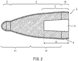
- FIG. 1 is a longitudinal cross-sectional view of a plug 1 according to an embodiment of the present invention.
- the plug 1 is projectile-shaped.
- the plug 1 includes a tip portion 2 and a trunk portion 3.
- the plug 1 has a transverse cross section that is circular in shape, as measured at each of the tip portion 2 and trunk portion 3.
- the surfaces of the tip portion 2 and trunk portion 3 form a continuous face.
- the tip portion 2 and trunk portion 3 are formed from the same material and constitute a single part.
- the direction toward the tip portion 2 will be hereinafter referred to as toward the front/tip or forward, while the direction toward the trunk portion 3 will be referred to as toward the rear or rearward.
- the trunk portion 3 includes a joining hole 4 opening on the rear end surface (i.e., back face) that allows for connection with a bar.
- the front end of the joining hole 4 i.e., bottom of the hole
- a rear portion of the plug 1 i.e., rear portion of the trunk portion 3) is cylindrical in shape due to the presence of the joining hole 4.
- a portion of the plug 1 extending in the longitudinal direction (or axial direction) and having the joining hole 4 inside will be referred to as cylindrical portion 5.
- the front end of the cylindrical portion 5 is located 0.1 ⁇ D [mm] forward of the front end of the joining hole 4, where D [mm] is the distance between the front end of the joining hole 4 and the rear end thereof (i.e., opening end) as measured in the longitudinal direction of the plug 1, i.e., depth of the joining hole 4. That is, as measured in the longitudinal direction of the plug 1, the cylindrical portion 5 is the portion of the plug 1 located between the position 0.1 ⁇ D [mm] forward of the front end of the joining hole 4 and the rear end of the plug 1.
- the plug 1 may further include a roll-off portion located rearward of the trunk portion 3.
- the plug 1 may be shaped to have a tip portion 2 protruding in a convex manner.
- the plug 1 shown in FIG. 2 further includes a roll-off portion 10 located rearward of the trunk portion 3.
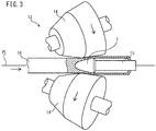
- the plug 1 is used in the piercing/rolling mill 13 for piercing/rolling, where the tip of a bar (or mandrel) 15 is attached into the joining hole 4.
- the plug 1 is positioned on a pass line PL between a pair of skewed rolls 14.
- the plug 1 starting with its tip portion 2, contacts a solid billet 16.
- the plug 1 is exposed to high temperatures and receives high pressures.
- the plug 1 is divided into a rolling portion 11 and a reeling portion 12.
- the rolling portion 11 is represented by the entire tip portion 2 and a front portion of the trunk portion 3 contiguous to the tip portion 2, and the reeling portion 12 is the portion of the trunk portion 3 located rearward of the rolling portion 11.
- the rolling portion 11 receives a major part of the thickness-reducing rolling during piercing/rolling.
- the reeling portion 12 finishes the wall thickness of a hollow shell (or simply shell) during piercing/rolling.
- the tip portion 2 is harder than the cylindrical portion 5.
- the Vickers hardness of the tip portion 2 is preferably not lower than 300 Hv, and more preferably not lower than 350 Hv.
- the Vickers hardness of the cylindrical portion 5 is preferably 220 to 260 Hv.
- Vickers hardness is a value provided by a measurement on a cross section of the plug 1 along the longitudinal direction in accordance with JIS Z 2244 (2009), with a testing force of 1 kgf.
- the cylindrical portion 5 preferably has an amount of absorbed energy not smaller than 25 J/cm 2 .
- the amount of absorbed energy of the cylindrical portion 5 is preferably not smaller than 30 J/cm 2 , and more preferably not smaller than 50 J/cm 2 .
- a tip portion 2 that is harder than the cylindrical portion 5 prevents the deformation of the tip portion 2 due to piercing/rolling. If the cylindrical portion 5 is as hard as the tip portion 2, this means a low toughness of the cylindrical portion 5, in which case piercing/rolling causes cracking in the cylindrical portion 5.
- the plug 1 of the present embodiment is a plug having a tip portion 2 and a trunk portion 3 formed from the same material, where only the tip portion 2 has a relatively high hardness, and thus provides a tip portion 2 with improved hardness and a cylindrical portion 5 having a desired toughness. As a result, the plug 1 prevents deformation of the tip portion 2 while preventing cracking in the cylindrical portion 5, thus increasing recyclability.
- the plug 1 further includes a protective layer 8.
- the protective layer 8 includes at least one of a sprayed coating and a build-up layer.
- the plug 1 may include both a sprayed coating and a build-up layer that provide the protective coating 8.
- a sprayed coating may be formed on some portions of the surface of the plug 1 and a build-up layer may be formed on other portions of the plug surface.
- a build-up layer and a sprayed coating may formed on the surface of the plug 1 so as to overlie each other.
- the sprayed coating is not limited to a particular one, it may be a sprayed coating mainly composed of iron and iron oxides, for example.
- the build-up layer is not limited to a particular one, it may be an alloy mainly composed of a transition metal, for example. This alloy may be, for example, an alloy mainly composed of cobalt and containing chromium and tungsten (i.e., Stellite alloy).
- the protective layer 8 preferably covers those portions of the plug surface included in the rolling portion 11. More preferably, the protective layer 8 covers the entire surface of the plug except for the rear end surface. It is preferable that the thickness of the protective layer 8 vary depending on the position, and it is preferable that the portion of the protective layer 8 provided on the surface of the tip portion 2 be thicker than the portion of the protective layer 8 provided on the surface of the trunk portion 3.
- FIGS. 1 and 2 depict implementations where the plug 1 includes a protective layer 8. Nevertheless, a protective layer 8 is only provided if necessary.
- the plug of the present embodiment may not include a protective layer 8.
- FIG. 4 is a flow chart of a method of manufacturing the plug according to an embodiment of the present invention.
- the manufacture method includes a step where a plug is prepared, S1: a step where a protective layer is formed on the plug, S2; a step where the plug is heated, S3; and a step where the plug is cooled, S4.
- a plug is prepared.
- a plug may be produced, for example, in the following manner: A steel having a chemical composition as specified above is melted and cast into a shape close to a plug shape, providing a roughly shaped product. An annealing process is performed in which the roughly shaped product is held at 650 to 850 °C for 2 to 6 hours and is then cooled in the furnace. Thereafter, the roughly shaped product is machined to provide the final plug shape.
- a protective layer 8 is formed on the plug as necessary. If the protective layer 8 is a sprayed coating, it may be formed by arc spraying, plasma spraying, flame spraying, or high-speed flame spraying, for example. If the protective layer 8 is a build-up layer, it may be formed by plasma powder build-up welding, MIG welding, or TIG welding, for example.
- Step S2 is optional. That is, step S2 may not be performed. Further, although FIG. 3 illustrates an implementation in which step S2 precedes step S3, step S2 is not limited to this timing. Although it is preferable that step S2 precede step S3, step S2 may be performed after steps S3 or S4.
- the tip portion 2 of the plug is heated.
- the heating is such that the temperature of the tip portion 2 rises to the austenite transformation temperature (i.e., A C3 point) or higher and the temperature of the cylindrical portion 5 remains below the A C3 point.
- the cylindrical portion 5, which should remain at temperatures below the A C3 point, is, as discussed above, the portion located between the position 0.1 ⁇ D [mm] forward of the front end of the joining hole 4 and the rear end of the plug. In other words, the region defined by the rear end of the plug and the position 0.1 ⁇ D [mm] forward of the front end of the joining hole 4 is heated so as to remain below the A C3 point.
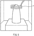
- a high-frequency coil 6 may be attached to the outer periphery of the tip portion 2, and the plug may be placed in a heating apparatus before the coil 6 is used to perform high-frequency heating on the tip portion 2 at a temperature of 950 to 1200 °C. More preferably, the heating temperature is 950 to 1100 °C.
- the heating is only required to be done for a period of time sufficient to cause the portion to be hardened; if high-frequency heating is used, the heating only needs to be done for several seconds at a temperature that is not lower than the A C3 point; however, to achieve industrial stability, the heating time is preferably 20 seconds or longer, and more preferably one minute or longer.
- the heating time is preferably not longer than 20 minutes, and more preferably not longer than 10 minutes. Particularly, if the heating treatment is performed in an environment other than an inert gas atmosphere (for example, in the ambient air), the heating time is preferably not longer than 10 minutes, and more preferably not longer than 5 minutes, because heating for a prolonged period of time may cause a change to the nature of the protective layer 8. For example, in the ambient air, the protective layer 8 may be oxidized to an unacceptable degree.
- the heating treatment discussed above makes it possible to raise the temperature of the tip portion 2 to a level that is not lower than the A C3 point and maintain the temperature of the cylindrical portion 5 below the A C3 point.
- the device for heating the plug is not limited to a high-frequency coil 6.
- FIG. 6 shows an example of an apparatus for heating the plug without the use of a high-frequency coil 6.
- the heating apparatus 7 shown in FIG. 6 includes heaters 71 and 72.
- the heater 71 is located adjacent to the top of the heating apparatus 7.
- the heater 72 is located adjacent to the bottom of the heating apparatus 7.
- the plug is loaded into the heating apparatus 7.
- a plurality of plugs are loaded into the heating apparatus 7.
- a shield 8 is placed between the plugs and heater 72. That is, the shield 8 is positioned above the heater 72 and the plugs are mounted on the shield 8.
- the shield 8 reduces transmission of heat from the heater 72 to the plugs.
- the shield 8 may be shaped as a grid or a plate, for example.
- the shield 8 may be coated with an oxide.
- the plugs in the heating apparatus 7 are heated by the heaters 71 and 72.
- the heaters 71 and 72 may operate at the same heating temperature (preset temperature).
- the heating apparatus 7 contains an inert gas atmosphere, such as Ar.
- the shield 8 works such that the amount of heat transmitted to the lower portion of each plug is smaller than the amount of heat transmitted to the upper portion of the plug, the temperature of the cylindrical portion 5 is lower than the temperature of the tip portion 2.
- the temperature of the cylindrical portion 5 has not reached the A C3 point and is below the A C3 point.
- the plugs may be heated by the heating apparatus 7 without a shield 8. If this is the case, the heating temperature of the heater 72 located below the plugs is adjusted to be lower than the heating temperature of the heater 71 located above the plugs. This ensures that the amount of heat transmitted to the upper portion of each plug is relatively large and the amount of heat transmitted to the lower portion of the plug is relatively small. Thus, as is the case with implementations using the shield 8, the plug may be heated such that the temperature of the tip portion 2 rises to the A C3 point or higher and the temperature of the cylindrical portion 5 remains below the A C3 point.
- a thermocouple may be attached to each of the tip portion 2 and cylindrical portion 5 of each plug in the heating apparatus 7, for example, to measure the temperature of the associated tip portion 2 or cylindrical portion 5. This makes it possible to detect that the temperature of the tip portion 2 has reached a predetermined temperature that is not lower than the A C3 point while the temperature of the cylindrical portion 5 is below the A C3 point, and remove the plug from the heating apparatus 7 at a suitable moment.
- the temperatures of the tip portion 2 and cylindrical portion 5 need not be measured each time step S3 is performed.
- An appropriate heating time can be learned by performing temperature measurement once, and this heating time can be used for plugs of the same type to perform step S3.
- the plug which has been heated at step S3 is cooled.
- power supply to the coil 6 is stopped and the door of the heating apparatus is opened to cool the plug to a temperature not higher than 400 °C, typically to room temperature. This results in a plug 1.
- the cooling rate is only required to be sufficient to cause the plug to be hardened, and the plug may generally be left to cool or may be cooled at a higher rate.
- the tip portion 2 is heated to a temperature not lower than the A C3 point to improve the hardness of the tip portion 2. Further, in the plug 1, the decrease in the toughness of the cylindrical portion 5 due to the heating can be reduced by keeping the temperature of the cylindrical portion 5 below the A C3 point. As a result, the plug 1 includes a tip portion 2 with improved hardness and a cylindrical portion 5 having a desired toughness.
- the manufacture of the plug 1 is not limited to the above-described method.
- only the cylindrical portion 5 may be tempered to produce a plug 1 with a tip portion 2 having a higher hardness than the cylindrical portion 5.
- a plug may be prepared where the entire plug (i.e., tip portion 2 and trunk portion 3) has a Vickers hardness of 300 Hv or higher, and only the cylindrical portion 5 may be tempered to produce a plug 1 with a tip portion 2 having a Vickers hardness of 300 Hv or higher and a cylindrical portion 5 having a Vickers hardness of 220 to 260 Hv.
- the roughly shaped plug product that had been cast was subjected to an annealing process in which the plug was held at 800 °C for 4 hours in the ambient air and was then cooled in the furnace. Thereafter, the outer surface was machined to provide a predetermined test-plug shape. For each composition, a plug provided with an Fe sprayed coating and a plug without such a coating were fabricated.
- Each of the plugs with and without a sprayed coating was heated in an Ar atmosphere such that the tip portion was in the range of 900 to 1100 °C and the temperature of the cylindrical portion was below 800 °C.
- the heating was performed by a heating apparatus including a high-frequency coil as described with reference to FIG. 4 , and the heating time was 10 minutes. After the heating, the door of the heating apparatus was opened and the plug was left to cool to near room temperature.
- a Charpy test specimen was prepared by taking a sample from the cylindrical portion of each plug without a sprayed coating and machining it, and Charpy impact testing was conducted to measure the amount of absorbed energy.
- the Charpy impact testing used a full-size test specimen in accordance with JIS Z 2242 (2005), which was measured at 40 °C.
- test specimen for hardness measurement was prepared by taking a sample from the tip portion of a plug without a sprayed coating and machining it, and its Vickers hardness was measured at normal temperature. The measurement of Vickers hardness was done in accordance with JIS Z 2244 (2009). The testing force was 1 kgf.
- Each plug with a sprayed coating was used to conduct 3 passes of piercing/rolling testing, where piercing/rolling was performed on a billet made of SUS 304, and the plug after piercing/rolling was observed to determine the presence/absence of a crack and the amount of base-material deformation (i.e., length of contraction in the L direction) was measured. Further, after the piercing/rolling, the sprayed coating was removed by shot blasting, and the plug after the removal of the sprayed coating was observed to determine the presence/absence of a chip.
- Test No. 1 The plug labeled Test No. 1 was the same that was described in WO 2017/051632 .
- the amounts of base-material deformation were evaluated with reference to the amount of base-material deformation of Test No. 1.
- the plug labeled Test No. 2 was the same as the reference except that the Cr content was 1.0 % (Composition B). This plug exhibited a reduced amount of base-material deformation compared with the plug of Test No. 1; still, the effect was small.
- the plug labeled Test No. 3 had a Cr content of 2.0 % (Composition C). It provided a toughness (or Charpy absorbed energy) substantially equal to that of the plug of Test No. 1 and, in addition, had a hardness at normal temperature improved by 20 % or more and, as a result, an amount of base-material deformation reduced by about 20 %. Further, no cracking nor chipping occurred.
- the plugs labeled Test Nos. 5 to 8 had a Cr content of 3.0 % (Composition D). Each of these plugs provided a toughness substantially equal to that of the plug of Test No. 1 and, in addition, had a hardness at normal temperature improved by about 30 % and, as a result, a significantly reduced amount of base-material deformation. Further, no cracking nor chipping occurred. Furthermore, these plugs had Mo and W contents that were half those of the plug of Test No. 1, and are expected to lead to cost reductions.
- Test Nos. 9 to 12 had incremental C contents relative to Composition D (Compositions E to H).
- the hardness at normal temperature was found to tend to increase as the C content increased, and the amount of base-material deformation decreased correspondingly.
- the toughness tended to decrease as the C content increased; cracking occurred in the plug of Test No. 12.
- the plug labeled Test No. 13 had a C content of 0.30 % and a Cr content of 4.0 % (Composition I).
- the plug of Test No. 13 had a hardness at normal temperature substantially equal to that of the plug of Test No. 11 (Composition G). It had a lower toughness than the plug of Test No. 11, but developed no cracks.
- the plug labeled Test No. 14 had a C content of 0.30 % and a Cr content of 5.0 % (Composition J). Cracking and chipping occurred in the plug of Test No. 14.
- the plug labeled Test No. 15 was the same as the plug of Test No. 14 except that the heat-treatment temperature was 950 °C.
- the plug of Test No. 15 developed no cracks, but suffered chipping.
- Test Nos. 16 to 18 were the same as the plug of Test No. 3 (Composition C) except that they additionally contained V, Nb and Ti, respectively (Compositions K, L and M). Due to the effect of V, Nb or Ti of making grains finer, these plugs had improved normal-temperature hardness and toughness compared with the plug of Test No. 3.
- the plug labeled Test No. 19 was the same as the plug of Test No. 6 (Composition D) except that it additionally contained B (Composition N). Due to the effect of B of improving grain-boundary strength, this plug had improved normal-temperature hardness and toughness compared with the plug of Test No. 6.
Landscapes
- Chemical & Material Sciences (AREA)
- Engineering & Computer Science (AREA)
- Materials Engineering (AREA)
- Mechanical Engineering (AREA)
- Metallurgy (AREA)
- Organic Chemistry (AREA)
- Physics & Mathematics (AREA)
- Plasma & Fusion (AREA)
- Chemical Kinetics & Catalysis (AREA)
- Crystallography & Structural Chemistry (AREA)
- Thermal Sciences (AREA)
- Heat Treatment Of Articles (AREA)
- Tires In General (AREA)
- Insertion Pins And Rivets (AREA)
- Snaps, Bayonet Connections, Set Pins, And Snap Rings (AREA)
- Contacts (AREA)
Claims (8)
- Lochdorn mit einer chemischen Zusammensetzung folgender Elemente von in Masse-%:0,15 bis 0,30 % an C;0,4 bis 1,2 % an Si;0,2 bis 1,5 % an Mn;0,1 bis 2,0 % an Ni;0 bis 4,0 % an Mo und 0 bis 4,0 % an W, wobei ein Gesamtgehalt an Mo und W 1,0 bis 6,0 % beträgt;1,2 % oder höher und nicht höher als 4,0 % an Cr;0 bis 0,2 % an B;0 bis 1,0 % an Nb;0 bis 1,0 % an V;0 bis 1,0 % an Ti; undes sich bei dem Rest um Fe und Verunreinigungen handelt,wobei der Dorn umfasst:einen Spitzenabschnitt; undeinen Hauptabschnitt, der aus demselben Material hergestellt ist wie der Spitzenabschnitt und in den Spitzenabschnitt übergeht,wobei der Hauptabschnitt einen zylindrischen Abschnitt mit einer Öffnung aufweist, die verwendet wird, um eine Stange zu montieren,wobei der Spitzenabschnitt härter ist als der zylindrische Abschnitt.
- Lochdorn nach Anspruch 1, darüber hinaus umfassend:eine Schutzschicht, die auf einer Oberfläche des Lochdorns ausgebildet ist,wobei die Schutzschicht eine aufgesprühte Schicht und/oder eine aufgebaute Schicht aufweist.
- Lochdorn nach Anspruch 2, wobei
die Schutzschicht die gesamte Oberfläche des Dorns, mit Ausnahme einer hinteren Endfläche bedeckt. - Lochdorn nach Anspruch 2 oder 3, wobei
die Dicke der Schutzschicht in Abhängigkeit von der Position variiert und ein Teil der Schutzschicht, der auf der Oberfläche des Spitzenabschnitts vorgesehen ist, dicker ist als ein Teil der Schutzschicht, der auf der Oberfläche des Hauptabschnitts vorgesehen ist. - Lochdorn nach einem der Ansprüche 1 bis 4, wobei
eine Vickers-Härte des Spitzenabschnitts nicht niedriger als 300 Hv ist, und
eine Vickers-Härte des zylindrischen Abschnitts 220 bis 260 Hv beträgt; und
es sich bei der Vickers-Härte um einen Wert handelt, der durch eine Messung an einem Querschnitt des Dorns 1 entlang der Längsrichtung in Übereinstimmung mit JIS Z 2244 (2009) mit einer Prüfkraft von 1 kgf geliefert wird. - Lochdorn nach einem der Ansprüche 1 bis 5, wobei
der zylindrische Abschnitt eine Menge an absorbierter Energie von nicht unter 25 J/cm2 hat, wie in einem Charpy-Schlagzähigkeitstest unter Verwendung eines Prüfkörpers voller Größe in Übereinstimmung mit JIS Z 2242 (2005) bei 40°C gemessen. - Verfahren zum Herstellen eines Lochdorns, das die folgenden Schritte umfasst:Vorbereiten eines Lochdorns mit einer chemischen Zusammensetzung folgender Elemente von in Masse-%: 0,15 bis 0,30 % an C; 0,4 bis 1,2 % an Si; 0,2 bis 1,5 % an Mn; 0,1 bis 2,0 % an Ni; 0 bis 4,0 % an Mo und 0 bis 4,0 % an W, wobei ein Gesamtgehalt an Mo und W 1,0 bis 6,0 % beträgt; 1,2 % oder höher und nicht höher als 4,0 % an Cr; 0 bis 0,2 % an B; 0 bis 1,0 % an Nb; 0 bis 1,0 % an V; 0 bis 1,0 % an Ti; und es sich bei dem Rest um Fe und Verunreinigungen handelt, wobei der Dorn einen Spitzenabschnitt und einen Hauptabschnitt aufweist, der aus demselben Material hergestellt ist wie der Spitzenabschnitt und in den Spitzenabschnitt übergeht; undErwärmen des Lochdorns auf eine solche Weise, dass sich der Spitzenabschnitt auf einer Temperatur befindet, die nicht niedriger ist als ein Acs-Punkt, und ein zylindrischer Abschnitt des Hauptabschnitts, der eine Öffnung hat, die verwendet wird, um eine Stange zu montieren, sich auf einer Temperatur unter dem Acs-Punkt befindet.
- Verfahren zum Herstellen eines Lochdorns nach Anspruch 7, darüber hinaus umfassend:vor dem Schritt des Erwärmens, den Schritt des Ausbildens einer Schutzschicht auf einer Oberfläche des Lochdorns,wobei die Schutzschicht eine aufgesprühte Schicht und/oder eine aufgebaute Schicht aufweist.
Applications Claiming Priority (2)
| Application Number | Priority Date | Filing Date | Title |
|---|---|---|---|
| JP2017212753 | 2017-11-02 | ||
| PCT/JP2018/029879 WO2019087510A1 (ja) | 2017-11-02 | 2018-08-09 | ピアサープラグ及びその製造方法 |
Publications (3)
| Publication Number | Publication Date |
|---|---|
| EP3705591A4 EP3705591A4 (de) | 2020-09-09 |
| EP3705591A1 EP3705591A1 (de) | 2020-09-09 |
| EP3705591B1 true EP3705591B1 (de) | 2021-03-17 |
Family
ID=66332981
Family Applications (1)
| Application Number | Title | Priority Date | Filing Date |
|---|---|---|---|
| EP18874192.0A Active EP3705591B1 (de) | 2017-11-02 | 2018-08-09 | Lochdorn und herstellungsverfahren dafür |
Country Status (7)
| Country | Link |
|---|---|
| US (1) | US11214855B2 (de) |
| EP (1) | EP3705591B1 (de) |
| JP (1) | JP6860083B2 (de) |
| CN (1) | CN111315906A (de) |
| BR (1) | BR112020002943B1 (de) |
| MX (1) | MX2020004442A (de) |
| WO (1) | WO2019087510A1 (de) |
Cited By (1)
| Publication number | Priority date | Publication date | Assignee | Title |
|---|---|---|---|---|
| EP3767002B1 (de) * | 2018-03-14 | 2024-08-28 | Nippon Steel Corporation | Lochdorn |
Families Citing this family (8)
| Publication number | Priority date | Publication date | Assignee | Title |
|---|---|---|---|---|
| EP3498388B1 (de) * | 2016-08-08 | 2020-08-26 | Nippon Steel Corporation | Verfahren zur herstellung eines durchstechsteckers |
| JP7406101B2 (ja) * | 2020-04-27 | 2023-12-27 | 日本製鉄株式会社 | 溶射材及び穿孔プラグの製造方法 |
| CN114107821B (zh) * | 2021-11-26 | 2022-07-08 | 钢铁研究总院 | 一种高韧性超高强度钢及其制造方法 |
| US20240254589A1 (en) * | 2023-02-01 | 2024-08-01 | Raytheon Technologies Corporation | Selective heat treatment of metals using a coil-in-furnace system |
| US20240254611A1 (en) * | 2023-02-01 | 2024-08-01 | Raytheon Technologies Corporation | Single-step process for selective heat treatment of metals using multiple heating sources |
| CN116393515B (zh) * | 2023-06-09 | 2023-08-04 | 太原理工大学 | 一种无缝金属复合管界面热力可控连续轧制设备及方法 |
| CN117600772A (zh) * | 2023-11-06 | 2024-02-27 | 众山(常州)新材料有限公司 | 一种用于带温轧制钛合金管的芯棒的制造方法及其应用 |
| CN118422078B (zh) * | 2024-05-17 | 2024-12-10 | 南通市嘉业机械制造有限公司 | 一种高强无缝钢管穿孔顶头的制备工艺 |
Family Cites Families (28)
| Publication number | Priority date | Publication date | Assignee | Title |
|---|---|---|---|---|
| US3655244A (en) * | 1970-07-30 | 1972-04-11 | Int Tool Sales | Impact driven tool with replaceable cutting point |
| JPS5440741B2 (de) | 1973-02-28 | 1979-12-05 | ||
| JPS57143471A (en) * | 1981-02-28 | 1982-09-04 | Daido Steel Co Ltd | High-speed steel |
| JPS62244505A (ja) * | 1986-04-17 | 1987-10-24 | Nippon Kokan Kk <Nkk> | 継目無管製造用プラグ |
| JPH02224806A (ja) * | 1989-02-28 | 1990-09-06 | Nkk Corp | 継目無し鋼管製造用プラグ |
| JP2778140B2 (ja) | 1989-07-28 | 1998-07-23 | 住友金属工業株式会社 | Ni基合金製熱間工具及びその熱間工具の後処理方法 |
| JP2819906B2 (ja) | 1991-12-27 | 1998-11-05 | 住友金属工業株式会社 | 室温および高温強度に優れた工具用Ni基合金 |
| JP2683861B2 (ja) | 1993-08-24 | 1997-12-03 | 住友金属工業株式会社 | 熱間製管用工具及びその製造方法 |
| JP2776256B2 (ja) | 1994-08-08 | 1998-07-16 | 住友金属工業株式会社 | 熱間加工用表面処理工具 |
| JPH08309108A (ja) * | 1995-05-19 | 1996-11-26 | Hitachi Kiden Kogyo Ltd | スカムの抑制方法 |
| JPH09195002A (ja) * | 1995-11-16 | 1997-07-29 | Sumitomo Metal Ind Ltd | 継目無管製造用プラグおよび継目無管の製造方法 |
| JPH10137818A (ja) * | 1996-11-05 | 1998-05-26 | Kawasaki Steel Corp | 継目無鋼管穿孔圧延用プラグ |
| JPH10291008A (ja) * | 1997-04-18 | 1998-11-04 | Sumitomo Metal Ind Ltd | 熱間製管用工具及びその製造方法 |
| JP3292122B2 (ja) * | 1997-12-19 | 2002-06-17 | 日本鋼管株式会社 | 継目無鋼管製造用工具 |
| JP4126979B2 (ja) * | 2002-07-15 | 2008-07-30 | 住友金属工業株式会社 | マルテンサイト系ステンレス継目無鋼管とその製造方法 |
| WO2004101837A1 (ja) * | 2003-05-13 | 2004-11-25 | Sumitomo Metal Industries, Ltd. | 熱間加工用工具鋼、熱間加工用工具および継目無管製造用プラグ |
| JP4347747B2 (ja) * | 2004-05-28 | 2009-10-21 | 日新製鋼株式会社 | 打抜き刃用鋼板並びに打抜き刃およびその製造法 |
| JP4380487B2 (ja) * | 2004-09-28 | 2009-12-09 | 住友金属工業株式会社 | マルテンサイト系ステンレス鋼管の製造方法 |
| CN101078092A (zh) * | 2006-05-23 | 2007-11-28 | 马中亮 | 一种穿孔顶头 |
| JP5523373B2 (ja) * | 2011-02-18 | 2014-06-18 | 三菱マテリアル株式会社 | 掘削用中空鋼ロッドとその製造方法 |
| MX353551B (es) | 2012-04-11 | 2018-01-17 | Nippon Steel & Sumitomo Metal Corp | Tarugo para uso en máquina perforadora y método de regeneración de tarugo. |
| CA2866361C (en) * | 2012-04-24 | 2017-05-09 | Nippon Steel & Sumitomo Metal Corporation | Plug used in piercing machine |
| CA2875456C (en) * | 2012-07-20 | 2016-11-29 | Nippon Steel & Sumitomo Metal Corporation | Piercing plug |
| TWI487800B (zh) | 2012-09-28 | 2015-06-11 | Shinhokoku Steel Corp | And a method for manufacturing the same for producing a seamless steel pipe |
| CN104233100B (zh) * | 2014-08-29 | 2016-08-17 | 南通市嘉业机械制造有限公司 | 一种无缝钢管穿孔顶头 |
| CN104988416A (zh) * | 2015-05-26 | 2015-10-21 | 宝山钢铁股份有限公司 | 一种高合金钢管穿孔顶头及其制造方法 |
| WO2017051632A1 (ja) | 2015-09-25 | 2017-03-30 | 新日鐵住金株式会社 | ピアサープラグ及びその製造方法 |
| CN108025338B (zh) * | 2015-09-28 | 2019-11-05 | 日本制铁株式会社 | 芯棒及其制造方法 |
-
2018
- 2018-08-09 CN CN201880071094.8A patent/CN111315906A/zh active Pending
- 2018-08-09 US US16/646,739 patent/US11214855B2/en active Active
- 2018-08-09 WO PCT/JP2018/029879 patent/WO2019087510A1/ja not_active Ceased
- 2018-08-09 BR BR112020002943-2A patent/BR112020002943B1/pt active IP Right Grant
- 2018-08-09 MX MX2020004442A patent/MX2020004442A/es unknown
- 2018-08-09 JP JP2019549868A patent/JP6860083B2/ja active Active
- 2018-08-09 EP EP18874192.0A patent/EP3705591B1/de active Active
Non-Patent Citations (1)
| Title |
|---|
| None * |
Cited By (1)
| Publication number | Priority date | Publication date | Assignee | Title |
|---|---|---|---|---|
| EP3767002B1 (de) * | 2018-03-14 | 2024-08-28 | Nippon Steel Corporation | Lochdorn |
Also Published As
| Publication number | Publication date |
|---|---|
| WO2019087510A1 (ja) | 2019-05-09 |
| EP3705591A4 (de) | 2020-09-09 |
| US20200263282A1 (en) | 2020-08-20 |
| US11214855B2 (en) | 2022-01-04 |
| JPWO2019087510A1 (ja) | 2020-07-30 |
| CN111315906A (zh) | 2020-06-19 |
| MX2020004442A (es) | 2020-08-13 |
| BR112020002943B1 (pt) | 2023-01-17 |
| BR112020002943A2 (pt) | 2020-08-11 |
| JP6860083B2 (ja) | 2021-04-14 |
| EP3705591A1 (de) | 2020-09-09 |
Similar Documents
| Publication | Publication Date | Title |
|---|---|---|
| EP3705591B1 (de) | Lochdorn und herstellungsverfahren dafür | |
| US9410230B2 (en) | Powder-metallurgically produced, wear-resistant material | |
| EP2252717B1 (de) | Stahl, verfahren zur herstellung eines stahlrohlings und verfahren zur herstellung einer komponente für den stahl | |
| CN105821327B (zh) | 钢粉末和使用其的模具 | |
| US5853502A (en) | Carburizing steel and steel products manufactured making use of the carburizing steel | |
| CN104294268B (zh) | 一种耐磨导辊制备方法 | |
| JP4346780B2 (ja) | 耐熱耐摩耗複合構造部材およびその製造方法 | |
| EP0553388B1 (de) | Kaliberwalze | |
| EP3354361B1 (de) | Lochdorn und herstellungsverfahren dafür | |
| CN113732263B (zh) | 压铸用套筒及其制造方法 | |
| JP3896478B2 (ja) | 耐食性、耐摩耗性および耐焼付き性に優れた肉盛り用材料及び複合工具 | |
| JPH03122251A (ja) | 金属圧延用複合ロール及びその製造法 | |
| EP3498388B1 (de) | Verfahren zur herstellung eines durchstechsteckers | |
| JP2687732B2 (ja) | 金属圧延用複合ロール及びその製造法と圧延機 | |
| JPH04172113A (ja) | 冷間管圧延機用孔型ロール及びその製造方法 | |
| JP2000212699A (ja) | 溶接性および被削性に優れた工具鋼およびそれを用いた金型 | |
| JP2001020041A (ja) | 溶接性および被削性に優れた工具鋼ならびに工具、金型 | |
| JP2006289391A (ja) | 熱間圧延用複合ロールの製造方法及び熱間圧延用複合ロール | |
| WO2004046407A1 (en) | Special steel as hot-cool composite material and manufacturing process thereof | |
| JPH11222655A (ja) | 粉末高速度工具鋼およびその製造方法 |
Legal Events
| Date | Code | Title | Description |
|---|---|---|---|
| STAA | Information on the status of an ep patent application or granted ep patent |
Free format text: STATUS: THE INTERNATIONAL PUBLICATION HAS BEEN MADE |
|
| PUAI | Public reference made under article 153(3) epc to a published international application that has entered the european phase |
Free format text: ORIGINAL CODE: 0009012 |
|
| STAA | Information on the status of an ep patent application or granted ep patent |
Free format text: STATUS: REQUEST FOR EXAMINATION WAS MADE |
|
| 17P | Request for examination filed |
Effective date: 20200218 |
|
| A4 | Supplementary search report drawn up and despatched |
Effective date: 20200629 |
|
| AK | Designated contracting states |
Kind code of ref document: A1 Designated state(s): AL AT BE BG CH CY CZ DE DK EE ES FI FR GB GR HR HU IE IS IT LI LT LU LV MC MK MT NL NO PL PT RO RS SE SI SK SM TR |
|
| AX | Request for extension of the european patent |
Extension state: BA ME |
|
| REG | Reference to a national code |
Ref country code: DE Ref legal event code: R079 Ref document number: 602018014190 Country of ref document: DE Free format text: PREVIOUS MAIN CLASS: C22C0038000000 Ipc: C21D0009000000 |
|
| GRAP | Despatch of communication of intention to grant a patent |
Free format text: ORIGINAL CODE: EPIDOSNIGR1 |
|
| STAA | Information on the status of an ep patent application or granted ep patent |
Free format text: STATUS: GRANT OF PATENT IS INTENDED |
|
| RIC1 | Information provided on ipc code assigned before grant |
Ipc: C21D 1/18 20060101ALI20201106BHEP Ipc: C21D 9/00 20060101ALI20201106BHEP Ipc: C23C 4/131 20160101ALI20201106BHEP Ipc: C22C 38/02 20060101ALI20201106BHEP Ipc: C22C 38/00 20060101AFI20201106BHEP Ipc: C22C 38/54 20060101ALI20201106BHEP Ipc: C22C 38/46 20060101ALI20201106BHEP Ipc: C23C 4/129 20160101ALI20201106BHEP Ipc: C23C 4/134 20160101ALI20201106BHEP Ipc: C22C 38/48 20060101ALI20201106BHEP Ipc: C22C 38/44 20060101ALI20201106BHEP Ipc: B21B 19/04 20060101ALI20201106BHEP Ipc: C23C 4/06 20160101ALI20201106BHEP Ipc: C21D 6/00 20060101ALI20201106BHEP Ipc: C22C 38/04 20060101ALI20201106BHEP Ipc: C22C 38/50 20060101ALI20201106BHEP Ipc: C23C 4/18 20060101ALI20201106BHEP Ipc: C23C 28/02 20060101ALI20201106BHEP Ipc: C23C 4/11 20160101ALI20201106BHEP Ipc: C23C 4/02 20060101ALI20201106BHEP |
|
| RIC1 | Information provided on ipc code assigned before grant |
Ipc: C23C 28/02 20060101ALI20201120BHEP Ipc: C22C 38/44 20060101ALI20201120BHEP Ipc: C23C 4/134 20160101ALI20201120BHEP Ipc: C23C 4/129 20160101ALI20201120BHEP Ipc: C22C 38/48 20060101ALI20201120BHEP Ipc: C23C 4/06 20160101ALI20201120BHEP Ipc: C21D 6/00 20060101ALI20201120BHEP Ipc: B21B 19/04 20060101ALN20201120BHEP Ipc: C22C 38/02 20060101ALI20201120BHEP Ipc: C22C 38/54 20060101ALI20201120BHEP Ipc: C22C 38/46 20060101ALI20201120BHEP Ipc: C21D 9/00 20060101AFI20201120BHEP Ipc: C22C 38/04 20060101ALI20201120BHEP Ipc: C21D 1/18 20060101ALI20201120BHEP Ipc: C23C 4/131 20160101ALI20201120BHEP Ipc: C22C 38/50 20060101ALI20201120BHEP Ipc: C23C 4/11 20160101ALI20201120BHEP Ipc: C23C 4/02 20060101ALI20201120BHEP Ipc: C23C 4/18 20060101ALI20201120BHEP |
|
| RIN1 | Information on inventor provided before grant (corrected) |
Inventor name: SHIRASAWA, NAOYA Inventor name: HIDAKA, YASUYOSHI Inventor name: MIYAI, TATSUYA |
|
| DAV | Request for validation of the european patent (deleted) | ||
| DAX | Request for extension of the european patent (deleted) | ||
| INTG | Intention to grant announced |
Effective date: 20201214 |
|
| GRAS | Grant fee paid |
Free format text: ORIGINAL CODE: EPIDOSNIGR3 |
|
| GRAA | (expected) grant |
Free format text: ORIGINAL CODE: 0009210 |
|
| STAA | Information on the status of an ep patent application or granted ep patent |
Free format text: STATUS: THE PATENT HAS BEEN GRANTED |
|
| AK | Designated contracting states |
Kind code of ref document: B1 Designated state(s): AL AT BE BG CH CY CZ DE DK EE ES FI FR GB GR HR HU IE IS IT LI LT LU LV MC MK MT NL NO PL PT RO RS SE SI SK SM TR |
|
| REG | Reference to a national code |
Ref country code: GB Ref legal event code: FG4D |
|
| REG | Reference to a national code |
Ref country code: CH Ref legal event code: EP |
|
| REG | Reference to a national code |
Ref country code: DE Ref legal event code: R096 Ref document number: 602018014190 Country of ref document: DE |
|
| REG | Reference to a national code |
Ref country code: IE Ref legal event code: FG4D |
|
| REG | Reference to a national code |
Ref country code: AT Ref legal event code: REF Ref document number: 1372300 Country of ref document: AT Kind code of ref document: T Effective date: 20210415 |
|
| REG | Reference to a national code |
Ref country code: LT Ref legal event code: MG9D |
|
| PG25 | Lapsed in a contracting state [announced via postgrant information from national office to epo] |
Ref country code: NO Free format text: LAPSE BECAUSE OF FAILURE TO SUBMIT A TRANSLATION OF THE DESCRIPTION OR TO PAY THE FEE WITHIN THE PRESCRIBED TIME-LIMIT Effective date: 20210617 Ref country code: BG Free format text: LAPSE BECAUSE OF FAILURE TO SUBMIT A TRANSLATION OF THE DESCRIPTION OR TO PAY THE FEE WITHIN THE PRESCRIBED TIME-LIMIT Effective date: 20210617 Ref country code: HR Free format text: LAPSE BECAUSE OF FAILURE TO SUBMIT A TRANSLATION OF THE DESCRIPTION OR TO PAY THE FEE WITHIN THE PRESCRIBED TIME-LIMIT Effective date: 20210317 Ref country code: GR Free format text: LAPSE BECAUSE OF FAILURE TO SUBMIT A TRANSLATION OF THE DESCRIPTION OR TO PAY THE FEE WITHIN THE PRESCRIBED TIME-LIMIT Effective date: 20210618 Ref country code: FI Free format text: LAPSE BECAUSE OF FAILURE TO SUBMIT A TRANSLATION OF THE DESCRIPTION OR TO PAY THE FEE WITHIN THE PRESCRIBED TIME-LIMIT Effective date: 20210317 |
|
| REG | Reference to a national code |
Ref country code: AT Ref legal event code: MK05 Ref document number: 1372300 Country of ref document: AT Kind code of ref document: T Effective date: 20210317 |
|
| REG | Reference to a national code |
Ref country code: NL Ref legal event code: MP Effective date: 20210317 |
|
| PG25 | Lapsed in a contracting state [announced via postgrant information from national office to epo] |
Ref country code: SE Free format text: LAPSE BECAUSE OF FAILURE TO SUBMIT A TRANSLATION OF THE DESCRIPTION OR TO PAY THE FEE WITHIN THE PRESCRIBED TIME-LIMIT Effective date: 20210317 Ref country code: RS Free format text: LAPSE BECAUSE OF FAILURE TO SUBMIT A TRANSLATION OF THE DESCRIPTION OR TO PAY THE FEE WITHIN THE PRESCRIBED TIME-LIMIT Effective date: 20210317 Ref country code: LV Free format text: LAPSE BECAUSE OF FAILURE TO SUBMIT A TRANSLATION OF THE DESCRIPTION OR TO PAY THE FEE WITHIN THE PRESCRIBED TIME-LIMIT Effective date: 20210317 |
|
| PG25 | Lapsed in a contracting state [announced via postgrant information from national office to epo] |
Ref country code: NL Free format text: LAPSE BECAUSE OF FAILURE TO SUBMIT A TRANSLATION OF THE DESCRIPTION OR TO PAY THE FEE WITHIN THE PRESCRIBED TIME-LIMIT Effective date: 20210317 |
|
| PG25 | Lapsed in a contracting state [announced via postgrant information from national office to epo] |
Ref country code: LT Free format text: LAPSE BECAUSE OF FAILURE TO SUBMIT A TRANSLATION OF THE DESCRIPTION OR TO PAY THE FEE WITHIN THE PRESCRIBED TIME-LIMIT Effective date: 20210317 Ref country code: EE Free format text: LAPSE BECAUSE OF FAILURE TO SUBMIT A TRANSLATION OF THE DESCRIPTION OR TO PAY THE FEE WITHIN THE PRESCRIBED TIME-LIMIT Effective date: 20210317 Ref country code: CZ Free format text: LAPSE BECAUSE OF FAILURE TO SUBMIT A TRANSLATION OF THE DESCRIPTION OR TO PAY THE FEE WITHIN THE PRESCRIBED TIME-LIMIT Effective date: 20210317 Ref country code: SM Free format text: LAPSE BECAUSE OF FAILURE TO SUBMIT A TRANSLATION OF THE DESCRIPTION OR TO PAY THE FEE WITHIN THE PRESCRIBED TIME-LIMIT Effective date: 20210317 Ref country code: AT Free format text: LAPSE BECAUSE OF FAILURE TO SUBMIT A TRANSLATION OF THE DESCRIPTION OR TO PAY THE FEE WITHIN THE PRESCRIBED TIME-LIMIT Effective date: 20210317 |
|
| PG25 | Lapsed in a contracting state [announced via postgrant information from national office to epo] |
Ref country code: IS Free format text: LAPSE BECAUSE OF FAILURE TO SUBMIT A TRANSLATION OF THE DESCRIPTION OR TO PAY THE FEE WITHIN THE PRESCRIBED TIME-LIMIT Effective date: 20210717 Ref country code: SK Free format text: LAPSE BECAUSE OF FAILURE TO SUBMIT A TRANSLATION OF THE DESCRIPTION OR TO PAY THE FEE WITHIN THE PRESCRIBED TIME-LIMIT Effective date: 20210317 Ref country code: RO Free format text: LAPSE BECAUSE OF FAILURE TO SUBMIT A TRANSLATION OF THE DESCRIPTION OR TO PAY THE FEE WITHIN THE PRESCRIBED TIME-LIMIT Effective date: 20210317 Ref country code: PT Free format text: LAPSE BECAUSE OF FAILURE TO SUBMIT A TRANSLATION OF THE DESCRIPTION OR TO PAY THE FEE WITHIN THE PRESCRIBED TIME-LIMIT Effective date: 20210719 Ref country code: PL Free format text: LAPSE BECAUSE OF FAILURE TO SUBMIT A TRANSLATION OF THE DESCRIPTION OR TO PAY THE FEE WITHIN THE PRESCRIBED TIME-LIMIT Effective date: 20210317 |
|
| REG | Reference to a national code |
Ref country code: DE Ref legal event code: R097 Ref document number: 602018014190 Country of ref document: DE |
|
| PLBE | No opposition filed within time limit |
Free format text: ORIGINAL CODE: 0009261 |
|
| STAA | Information on the status of an ep patent application or granted ep patent |
Free format text: STATUS: NO OPPOSITION FILED WITHIN TIME LIMIT |
|
| PG25 | Lapsed in a contracting state [announced via postgrant information from national office to epo] |
Ref country code: ES Free format text: LAPSE BECAUSE OF FAILURE TO SUBMIT A TRANSLATION OF THE DESCRIPTION OR TO PAY THE FEE WITHIN THE PRESCRIBED TIME-LIMIT Effective date: 20210317 Ref country code: DK Free format text: LAPSE BECAUSE OF FAILURE TO SUBMIT A TRANSLATION OF THE DESCRIPTION OR TO PAY THE FEE WITHIN THE PRESCRIBED TIME-LIMIT Effective date: 20210317 Ref country code: AL Free format text: LAPSE BECAUSE OF FAILURE TO SUBMIT A TRANSLATION OF THE DESCRIPTION OR TO PAY THE FEE WITHIN THE PRESCRIBED TIME-LIMIT Effective date: 20210317 |
|
| 26N | No opposition filed |
Effective date: 20211220 |
|
| REG | Reference to a national code |
Ref country code: CH Ref legal event code: PL |
|
| PG25 | Lapsed in a contracting state [announced via postgrant information from national office to epo] |
Ref country code: MC Free format text: LAPSE BECAUSE OF FAILURE TO SUBMIT A TRANSLATION OF THE DESCRIPTION OR TO PAY THE FEE WITHIN THE PRESCRIBED TIME-LIMIT Effective date: 20210317 |
|
| REG | Reference to a national code |
Ref country code: BE Ref legal event code: MM Effective date: 20210831 |
|
| PG25 | Lapsed in a contracting state [announced via postgrant information from national office to epo] |
Ref country code: LI Free format text: LAPSE BECAUSE OF NON-PAYMENT OF DUE FEES Effective date: 20210831 Ref country code: CH Free format text: LAPSE BECAUSE OF NON-PAYMENT OF DUE FEES Effective date: 20210831 |
|
| PG25 | Lapsed in a contracting state [announced via postgrant information from national office to epo] |
Ref country code: IS Free format text: LAPSE BECAUSE OF FAILURE TO SUBMIT A TRANSLATION OF THE DESCRIPTION OR TO PAY THE FEE WITHIN THE PRESCRIBED TIME-LIMIT Effective date: 20210717 Ref country code: LU Free format text: LAPSE BECAUSE OF NON-PAYMENT OF DUE FEES Effective date: 20210809 |
|
| PG25 | Lapsed in a contracting state [announced via postgrant information from national office to epo] |
Ref country code: IE Free format text: LAPSE BECAUSE OF NON-PAYMENT OF DUE FEES Effective date: 20210809 Ref country code: BE Free format text: LAPSE BECAUSE OF NON-PAYMENT OF DUE FEES Effective date: 20210831 |
|
| GBPC | Gb: european patent ceased through non-payment of renewal fee |
Effective date: 20220809 |
|
| PG25 | Lapsed in a contracting state [announced via postgrant information from national office to epo] |
Ref country code: CY Free format text: LAPSE BECAUSE OF FAILURE TO SUBMIT A TRANSLATION OF THE DESCRIPTION OR TO PAY THE FEE WITHIN THE PRESCRIBED TIME-LIMIT Effective date: 20210317 |
|
| PG25 | Lapsed in a contracting state [announced via postgrant information from national office to epo] |
Ref country code: HU Free format text: LAPSE BECAUSE OF FAILURE TO SUBMIT A TRANSLATION OF THE DESCRIPTION OR TO PAY THE FEE WITHIN THE PRESCRIBED TIME-LIMIT; INVALID AB INITIO Effective date: 20180809 |
|
| PG25 | Lapsed in a contracting state [announced via postgrant information from national office to epo] |
Ref country code: SI Free format text: LAPSE BECAUSE OF FAILURE TO SUBMIT A TRANSLATION OF THE DESCRIPTION OR TO PAY THE FEE WITHIN THE PRESCRIBED TIME-LIMIT Effective date: 20210317 |
|
| PG25 | Lapsed in a contracting state [announced via postgrant information from national office to epo] |
Ref country code: GB Free format text: LAPSE BECAUSE OF NON-PAYMENT OF DUE FEES Effective date: 20220809 |
|
| PG25 | Lapsed in a contracting state [announced via postgrant information from national office to epo] |
Ref country code: MK Free format text: LAPSE BECAUSE OF FAILURE TO SUBMIT A TRANSLATION OF THE DESCRIPTION OR TO PAY THE FEE WITHIN THE PRESCRIBED TIME-LIMIT Effective date: 20210317 |
|
| PG25 | Lapsed in a contracting state [announced via postgrant information from national office to epo] |
Ref country code: MT Free format text: LAPSE BECAUSE OF FAILURE TO SUBMIT A TRANSLATION OF THE DESCRIPTION OR TO PAY THE FEE WITHIN THE PRESCRIBED TIME-LIMIT Effective date: 20210317 |
|
| PGFP | Annual fee paid to national office [announced via postgrant information from national office to epo] |
Ref country code: DE Payment date: 20250702 Year of fee payment: 8 |
|
| PGFP | Annual fee paid to national office [announced via postgrant information from national office to epo] |
Ref country code: IT Payment date: 20250722 Year of fee payment: 8 |
|
| PGFP | Annual fee paid to national office [announced via postgrant information from national office to epo] |
Ref country code: FR Payment date: 20250703 Year of fee payment: 8 |
|
| PG25 | Lapsed in a contracting state [announced via postgrant information from national office to epo] |
Ref country code: TR Free format text: LAPSE BECAUSE OF FAILURE TO SUBMIT A TRANSLATION OF THE DESCRIPTION OR TO PAY THE FEE WITHIN THE PRESCRIBED TIME-LIMIT Effective date: 20210317 |