WO2017051632A1 - ピアサープラグ及びその製造方法 - Google Patents
ピアサープラグ及びその製造方法 Download PDFInfo
- Publication number
- WO2017051632A1 WO2017051632A1 PCT/JP2016/073706 JP2016073706W WO2017051632A1 WO 2017051632 A1 WO2017051632 A1 WO 2017051632A1 JP 2016073706 W JP2016073706 W JP 2016073706W WO 2017051632 A1 WO2017051632 A1 WO 2017051632A1
- Authority
- WO
- WIPO (PCT)
- Prior art keywords
- plug
- tip
- piercer
- temperature
- rolling
- Prior art date
Links
Images

Classifications
-
- B—PERFORMING OPERATIONS; TRANSPORTING
- B21—MECHANICAL METAL-WORKING WITHOUT ESSENTIALLY REMOVING MATERIAL; PUNCHING METAL
- B21B—ROLLING OF METAL
- B21B25/00—Mandrels for metal tube rolling mills, e.g. mandrels of the types used in the methods covered by group B21B17/00; Accessories or auxiliary means therefor ; Construction of, or alloys for, mandrels or plugs
-
- C—CHEMISTRY; METALLURGY
- C21—METALLURGY OF IRON
- C21D—MODIFYING THE PHYSICAL STRUCTURE OF FERROUS METALS; GENERAL DEVICES FOR HEAT TREATMENT OF FERROUS OR NON-FERROUS METALS OR ALLOYS; MAKING METAL MALLEABLE, e.g. BY DECARBURISATION OR TEMPERING
- C21D6/00—Heat treatment of ferrous alloys
- C21D6/004—Heat treatment of ferrous alloys containing Cr and Ni
-
- C—CHEMISTRY; METALLURGY
- C21—METALLURGY OF IRON
- C21D—MODIFYING THE PHYSICAL STRUCTURE OF FERROUS METALS; GENERAL DEVICES FOR HEAT TREATMENT OF FERROUS OR NON-FERROUS METALS OR ALLOYS; MAKING METAL MALLEABLE, e.g. BY DECARBURISATION OR TEMPERING
- C21D6/00—Heat treatment of ferrous alloys
- C21D6/005—Heat treatment of ferrous alloys containing Mn
-
- C—CHEMISTRY; METALLURGY
- C21—METALLURGY OF IRON
- C21D—MODIFYING THE PHYSICAL STRUCTURE OF FERROUS METALS; GENERAL DEVICES FOR HEAT TREATMENT OF FERROUS OR NON-FERROUS METALS OR ALLOYS; MAKING METAL MALLEABLE, e.g. BY DECARBURISATION OR TEMPERING
- C21D6/00—Heat treatment of ferrous alloys
- C21D6/007—Heat treatment of ferrous alloys containing Co
-
- C—CHEMISTRY; METALLURGY
- C21—METALLURGY OF IRON
- C21D—MODIFYING THE PHYSICAL STRUCTURE OF FERROUS METALS; GENERAL DEVICES FOR HEAT TREATMENT OF FERROUS OR NON-FERROUS METALS OR ALLOYS; MAKING METAL MALLEABLE, e.g. BY DECARBURISATION OR TEMPERING
- C21D6/00—Heat treatment of ferrous alloys
- C21D6/008—Heat treatment of ferrous alloys containing Si
-
- C—CHEMISTRY; METALLURGY
- C21—METALLURGY OF IRON
- C21D—MODIFYING THE PHYSICAL STRUCTURE OF FERROUS METALS; GENERAL DEVICES FOR HEAT TREATMENT OF FERROUS OR NON-FERROUS METALS OR ALLOYS; MAKING METAL MALLEABLE, e.g. BY DECARBURISATION OR TEMPERING
- C21D9/00—Heat treatment, e.g. annealing, hardening, quenching or tempering, adapted for particular articles; Furnaces therefor
- C21D9/0068—Heat treatment, e.g. annealing, hardening, quenching or tempering, adapted for particular articles; Furnaces therefor for particular articles not mentioned below
-
- C—CHEMISTRY; METALLURGY
- C22—METALLURGY; FERROUS OR NON-FERROUS ALLOYS; TREATMENT OF ALLOYS OR NON-FERROUS METALS
- C22C—ALLOYS
- C22C38/00—Ferrous alloys, e.g. steel alloys
- C22C38/002—Ferrous alloys, e.g. steel alloys containing In, Mg, or other elements not provided for in one single group C22C38/001 - C22C38/60
-
- C—CHEMISTRY; METALLURGY
- C22—METALLURGY; FERROUS OR NON-FERROUS ALLOYS; TREATMENT OF ALLOYS OR NON-FERROUS METALS
- C22C—ALLOYS
- C22C38/00—Ferrous alloys, e.g. steel alloys
- C22C38/02—Ferrous alloys, e.g. steel alloys containing silicon
-
- C—CHEMISTRY; METALLURGY
- C22—METALLURGY; FERROUS OR NON-FERROUS ALLOYS; TREATMENT OF ALLOYS OR NON-FERROUS METALS
- C22C—ALLOYS
- C22C38/00—Ferrous alloys, e.g. steel alloys
- C22C38/04—Ferrous alloys, e.g. steel alloys containing manganese
-
- C—CHEMISTRY; METALLURGY
- C22—METALLURGY; FERROUS OR NON-FERROUS ALLOYS; TREATMENT OF ALLOYS OR NON-FERROUS METALS
- C22C—ALLOYS
- C22C38/00—Ferrous alloys, e.g. steel alloys
- C22C38/18—Ferrous alloys, e.g. steel alloys containing chromium
- C22C38/40—Ferrous alloys, e.g. steel alloys containing chromium with nickel
- C22C38/42—Ferrous alloys, e.g. steel alloys containing chromium with nickel with copper
-
- C—CHEMISTRY; METALLURGY
- C22—METALLURGY; FERROUS OR NON-FERROUS ALLOYS; TREATMENT OF ALLOYS OR NON-FERROUS METALS
- C22C—ALLOYS
- C22C38/00—Ferrous alloys, e.g. steel alloys
- C22C38/18—Ferrous alloys, e.g. steel alloys containing chromium
- C22C38/40—Ferrous alloys, e.g. steel alloys containing chromium with nickel
- C22C38/44—Ferrous alloys, e.g. steel alloys containing chromium with nickel with molybdenum or tungsten
-
- C—CHEMISTRY; METALLURGY
- C22—METALLURGY; FERROUS OR NON-FERROUS ALLOYS; TREATMENT OF ALLOYS OR NON-FERROUS METALS
- C22C—ALLOYS
- C22C38/00—Ferrous alloys, e.g. steel alloys
- C22C38/18—Ferrous alloys, e.g. steel alloys containing chromium
- C22C38/40—Ferrous alloys, e.g. steel alloys containing chromium with nickel
- C22C38/52—Ferrous alloys, e.g. steel alloys containing chromium with nickel with cobalt
-
- C—CHEMISTRY; METALLURGY
- C21—METALLURGY OF IRON
- C21D—MODIFYING THE PHYSICAL STRUCTURE OF FERROUS METALS; GENERAL DEVICES FOR HEAT TREATMENT OF FERROUS OR NON-FERROUS METALS OR ALLOYS; MAKING METAL MALLEABLE, e.g. BY DECARBURISATION OR TEMPERING
- C21D2211/00—Microstructure comprising significant phases
- C21D2211/001—Austenite
-
- C—CHEMISTRY; METALLURGY
- C21—METALLURGY OF IRON
- C21D—MODIFYING THE PHYSICAL STRUCTURE OF FERROUS METALS; GENERAL DEVICES FOR HEAT TREATMENT OF FERROUS OR NON-FERROUS METALS OR ALLOYS; MAKING METAL MALLEABLE, e.g. BY DECARBURISATION OR TEMPERING
- C21D9/00—Heat treatment, e.g. annealing, hardening, quenching or tempering, adapted for particular articles; Furnaces therefor
-
- C—CHEMISTRY; METALLURGY
- C22—METALLURGY; FERROUS OR NON-FERROUS ALLOYS; TREATMENT OF ALLOYS OR NON-FERROUS METALS
- C22C—ALLOYS
- C22C38/00—Ferrous alloys, e.g. steel alloys
-
- C—CHEMISTRY; METALLURGY
- C22—METALLURGY; FERROUS OR NON-FERROUS ALLOYS; TREATMENT OF ALLOYS OR NON-FERROUS METALS
- C22C—ALLOYS
- C22C38/00—Ferrous alloys, e.g. steel alloys
- C22C38/18—Ferrous alloys, e.g. steel alloys containing chromium
- C22C38/40—Ferrous alloys, e.g. steel alloys containing chromium with nickel
- C22C38/54—Ferrous alloys, e.g. steel alloys containing chromium with nickel with boron
Definitions
- the present invention relates to a piercer plug and a manufacturing method thereof, and particularly to a piercer plug used for piercing and rolling for manufacturing a seamless steel pipe and a manufacturing method thereof.
- a seamless steel pipe is manufactured by subjecting a heated billet to piercing and rolling by a piercing and rolling machine (Piercer).
- JP-A-7-96305 and JP-A-3-18901 disclose piercer plugs used for piercing and rolling. Piercer plugs are used in very harsh environments.
- Japanese Patent Laid-Open Nos. 2003-171733, 10-291008, 2668361 and 3635531 disclose a piercer plug in which wear of a material is suppressed by providing an oxide film on the surface of the material.
- Has been. JP 2013-248619 A, Japanese Patent No. 4279350 and Japanese Patent No. 5169882 disclose piercer plugs in which the wear of the material is suppressed by providing a thermal spray coating on the surface of the material. Any of these films is consumed by wear or peeling when used for perforation. Piercer plugs that have been depleted can be reused by interrupting use and re-forming the film.
- Japanese Patent No. 5464300 discloses a piercer plug in which a built-up layer is provided at the tip and a thermal spray coating is provided behind the built-up layer. This piercer plug suppresses deformation of the plug base material (material) by a high-strength overlay layer.
- Japanese Patent Laid-Open No. 10-156410 discloses that the body portion is made of 3Cr (chromium) -1Ni (nickel) based low alloy steel and the tip portion is made of Nb (niobium) alloy.
- a piercer plug is disclosed in which high-temperature strength is increased and deformation of the tip portion is suppressed.
- Japanese Examined Patent Publication No. 5-85242 discloses a piercer plug that includes a tip portion made of a heat-resistant alloy and a main body that is mounted so that the tip portion can be relatively rotated, thereby preventing deformation.
- the conventionally proposed piercer plug has a structure in which a built-up part is formed at the tip part or a structure in which a tip part made of a material different from the trunk part is attached to the trunk part, so that the manufacturing process is complicated. In addition, the manufacturing cost is also high.
- the entire piercer plug is made of a hard material, the toughness of the material decreases, and cracks may occur during piercing and rolling.
- the present inventors have found that cracks during piercing and rolling are for coupling provided in the piercer plug mainly for coupling the piercer plug and the bar (core metal). It was found that it originates from the hole.
- An object of the present invention is to provide a piercer plug in which a tip portion and a body portion are made of the same material, which suppresses deformation of the piercer plug, suppresses cracking, and prolongs the service life. That is.
- a piercer plug according to an embodiment of the present invention includes a tip portion and a body portion formed of the same material as the tip portion and continuous with the tip portion.
- the trunk portion includes a cylindrical portion in which a hole for attaching the bar is formed.
- the tip is harder than the tube.
- a method of manufacturing a piercer plug according to an embodiment of the present invention includes a step of preparing a piercer plug including a tip portion and a body portion that is formed of the same material as the tip portion and is continuous with the tip portion. Heating the piercer plug so that the temperature of the tube part in which the hole for attaching the bar is formed in the body part becomes lower than the austenite transformation temperature.
- the life of the piercer plug can be extended.
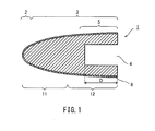
- FIG. 1 is a longitudinal sectional view of a piercer plug according to an embodiment of the present invention.
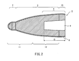
- FIG. 2 is a longitudinal sectional view of another piercer plug having a shape different from that of FIG.
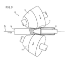
- FIG. 3 is a schematic diagram showing a configuration of a piercing and rolling mill provided with a piercer plug.
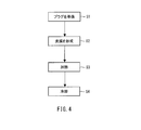
- FIG. 4 is a flowchart illustrating a manufacturing method according to an embodiment of the present invention.
- FIG. 5 is a schematic diagram of a heating device.
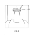
- FIG. 6 is a schematic view of a heating device different from the heating device shown in FIG.
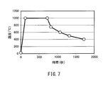
- FIG. 7 is a graph showing an example of a heat pattern.
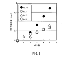
- FIG. 8 is a graph showing the relationship between the plug deformation amount and the number of passes.
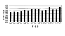
- FIG. 9 is a graph showing the Vickers hardness of the tip of the piercer plugs numbered 1 to 15.
- the piercer plug includes a tip portion and a body portion that is formed of the same material as the tip portion and is continuous with the tip portion.
- the trunk portion includes a cylindrical portion in which a hole for attaching the bar is formed.
- the tip is harder than the tube.
- This piercer plug has a tip part harder than the cylinder part and a cylinder part having higher toughness than the tip part. Therefore, when the piercer plug is used for piercing and rolling, deformation of the tip portion is suppressed and cracking of the cylindrical portion is suppressed. As a result, the piercer plug can be used for a larger number of piercing and rolling operations, and the life is increased.
- This piercer plug further includes a film formed on the surface of the piercer plug.
- a method of manufacturing a piercer plug includes a step of preparing a piercer plug including a tip portion and a body portion that is formed of the same material as the tip portion and is continuous with the tip portion, and the temperature of the tip portion is equal to or higher than the austenite transformation temperature and Heating the piercer plug so that the temperature of the cylinder part in which the hole for attaching the bar is formed in the trunk part is lower than the austenite transformation temperature.
- the piercer plug manufactured by this method has a tip part harder than the cylinder part and a cylinder part having higher toughness than the tip part. Therefore, when this piercer plug is used for piercing and rolling, deformation of the tip portion is suppressed and cracking of the cylindrical portion is suppressed. As a result, the piercer plug can be used for a larger number of piercing and rolling operations, and the life is increased.
- the manufacturing method of the piercer plug further includes a step of forming a film on the surface of the piercer plug prior to the heating step.
- the piercer plug manufactured by this method suppresses deformation of the rolled part by the film.
- Piercer plugs (hereinafter simply referred to as plugs) are repeatedly used in piercing and rolling machines (piercers) used in the production of seamless steel pipes.
- the material used for the plug is not particularly limited as long as it is a steel whose hardness is improved by heat treatment, that is, a steel that is baked.
- the plug is preferably formed by forging, but is not particularly limited thereto.
- the steel used as a material for the plug preferably contains characteristic elements in the following ranges in addition to Fe (iron) and impurities. In addition, you may contain other than these elements.
- % related to elements means mass%.
- Carbon (C) is an active ingredient for improving high temperature strength. If the C content is 0.08% or less, there is no effect. On the other hand, if the C content exceeds 0.5%, the hardness becomes too high. Moreover, it becomes difficult to control the precipitation state of the carbide. Therefore, the C content is 0.08 to 0.5%.
- the C content is preferably 0.3% or less, and more preferably 0.2% or less.
- the C content is preferably 0.09% or more, and more preferably 0.1% or more.
- Si 0.1 to 1.0%
- Silicon (Si) is an effective component for deoxidation. If the Si content is 0.1% or less, the effect is small. When the Si content exceeds 1.0%, the toughness of the material starts to deteriorate. Therefore, the Si content is set to 0.1 to 1.0%.
- the Si content is preferably 0.9% or less, and more preferably 0.8% or less.
- the Si content is preferably 0.2% or more, and more preferably 0.3% or more.
- Mn 0.2 to 1.5%
- Manganese (Mn) stabilizes austenite at high temperatures. That is, the formation of ⁇ ferrite is suppressed to suppress toughness reduction. The effect is obtained when the Mn content is 0.2% or more. However, if the Mn content exceeds 1.5%, the hardness becomes too high, and after the perforation, a burning crack is likely to occur. Therefore, the Mn content is 0.2 to 1.5%.
- the Mn content is preferably 1.4% or less, and more preferably 1.3% or less.
- the Mn content is preferably 0.3% or more, and more preferably 0.4% or more.
- the material may contain the following selective elements. That is, none of the following elements may be contained in the material. Moreover, only a part may be contained.
- Ni 0 to 2.0%
- Nickel (Ni) has the effect of improving the toughness of the quenched phase formed in the plug surface layer. The effect is almost saturated when the Ni content is 2.0%. Addition of more than that will increase the cost. Therefore, the Ni content is 0 to 2.0%.
- the Ni content is preferably 1.9% or less, and more preferably 1.8% or less.
- the Ni content is preferably 0.2% or more, and more preferably 0.3% or more.
- Mo 0 to 4.0%
- W 0 to 4.0%
- Molybdenum (Mo) and tungsten (W) are substitutable elements. These elements are effective in improving the high-temperature strength and have the effect of increasing the Ac1 point and reducing the portion where the surface is burned after drilling. However, if the total exceeds 8.0%, ferrite remains even at a high temperature, and the strength and toughness deteriorate. Therefore, the total sum is 8.0% or less.
- Mo content becomes like this. Preferably it is 3.9% or less, More preferably, it is 3.8% or less. Mo content becomes like this. Preferably it is 0.75% or more, More preferably, it is 0.8% or more. W content becomes like this. Preferably it is 3.9% or less, More preferably, it is 3.8% or less. W content becomes like this. Preferably it is 0.75% or more, More preferably, it is 0.8% or more.
- Copper (Cu) is an austenite stabilizing element, and has an effect of improving the toughness of the plug surface layer portion that is held at a high temperature during drilling to become austenite. Therefore, the Cu content is 0 to 0.5%.
- B 0 to 0.2%
- Nb 0 to 1.0%
- V 0 to 1.0%
- Cr 0 to 10.0%
- Ti 0 to 1.0%
- boron (B) is contained even a little, there is an effect of increasing the strength of the grain boundary. However, when the B content exceeds 0.2%, an embrittled phase is precipitated and the toughness deteriorates. Therefore, the B content is 0 to 0.2%.
- niobium (Nb), vanadium (V), chromium (Cr), and titanium (Ti) are contained in any amount, there is an effect of refining crystal grains. Therefore, the content of each of the elements Nb, V, and Ti is 0 to 1.0%, and the Cr content is 0 to 10.0%.
- calcium (Ca) and rare earth elements (REM) can be added in small amounts as necessary for the purpose of desulfurization.
- the plug 1 has, for example, a bullet shape as shown in FIG.
- the plug 1 includes a distal end portion 2 and a trunk portion 3.
- drum 3 are circular.
- the front end portion 2 and the body portion 3 have continuous surfaces.
- the tip portion 2 and the body portion 3 are formed of the same material and are one part.
- the front end 2 side is defined as the front
- the trunk 3 side is defined as the rear.
- drum 3 has the coupling hole 4 opened in the rear end surface (back surface) provided in order to connect with a bar.
- the front end (bottom of the hole) of the coupling hole 4 is located at the center or the rear part of the entire length of the plug 1 (the dimension from the front end of the front end portion 2 to the rear end of the body portion 3). .
- the rear portion of the plug 1 (the rear portion of the body portion 3) is formed into a cylindrical shape by the coupling hole 4.
- a portion in which the coupling hole 4 is formed is referred to as a cylindrical portion 5.
- the length from the front end to the rear end (open end) of the coupling hole 4 in the longitudinal direction of the plug 1, that is, the depth of the coupling hole 4 is D [mm], and the front end of the cylindrical portion 5 is the coupling hole 4.
- the position is 0.1 ⁇ D [mm] forward from the front end of each. That is, the cylindrical portion 5 indicates a portion between a position 0.1 ⁇ D [mm] ahead of the front end of the coupling hole 4 and the rear end of the plug 1 in the longitudinal direction of the plug 1.
- the plug 1 shown in FIG. 1 may further include an escape portion located behind the trunk portion 3.
- the plug 1 may have a shape in which the distal end portion 2 is formed to protrude in a convex shape.
- the plug 1 shown in FIG. 2 further includes an escape portion 10 located behind the trunk portion 3.
- the plug 1 is used for piercing and rolling by attaching the tip of a bar 15 (core metal) to the coupling hole 4 in the piercing and rolling mill 13.
- the plug 1 is disposed between the pair of inclined rolls 14 and 14 and on the pass line PL.
- the solid billet 16 is pushed from the tip end portion 2 of the plug 1, so that it is exposed to a high temperature and receives a high pressure.
- the plug 1 is divided into a rolling part 11 and a reeling part 12 as shown in FIG. 1 or FIG.
- the rolling part 11 is a front part continuous to the tip part 2 of the whole tip part 2 and the body part 3, and the reeling part 12 is a part behind the rolling part 11 of the body part 3.
- the rolling part 11 is a part responsible for most of the thickness reduction in piercing and rolling.
- the reeling portion 12 is a portion that finishes the thickness of a hollow shell (also referred to as a shell) in piercing and rolling.
- the plug 1 further includes a film 8.
- the coating 8 is, for example, a thermal spray coating mainly composed of iron and iron oxide formed by thermal spraying or a scale coating formed by an oxidation heat treatment.
- the film 8 is formed on the surface of the plug 1 and covers, for example, the entire surface of the plug (excluding the rear end surface provided with a cored bar coupling hole).
- the coating 8 may be formed on at least the rolled portion 11 on the plug surface, but is preferably formed on the entire surface except the rear end face of the plug. Further, the thickness of the coating 8 is preferably different for each part, and it is preferable to make the coating 8 formed on the surface of the distal end portion 2 thicker than the thickness of the coating 8 formed on the surface of the body portion 3.
- the tip 2 is harder than the tube 5.
- the tip portion 2 has a Vickers hardness of 300 Hv or more, while the tube portion 5 preferably has a Vickers hardness of 220 to 260 Hv, but may be 220 Hv or less.
- the Vickers hardness is a value measured from a cross section obtained by cutting the plug 1 in the longitudinal direction with a test force of 1 kgf based on JIS Z 2244 (2009).
- the cylinder part 5 is 20 J / cm ⁇ 2 > or more whose impact value in 20 degreeC is comparable to the conventional plug in the Charpy impact test using the full-size test piece based on JISZ2242 (2005).
- the plug 1 can suppress deformation of the distal end portion 2 due to piercing and rolling by making the distal end portion 2 harder than the cylindrical portion 5.
- the reduction amount of the total length (also referred to as plug deformation amount) due to the deformation of the tip portion 2 can be suppressed to about 50% of the conventional amount.
- the plug 1 can pierce and roll the billet with the same piercing efficiency as before.
- the plug 1 of the present embodiment is a plug in which the tip portion 2 and the body portion 3 are formed of the same material, and the tip portion 2 whose hardness is improved by hardening only the tip portion 2 and a tube having desired toughness. Part 5 can be provided. As a result, the plug 1 can suppress the deformation of the distal end portion 2 while suppressing the occurrence of cracks in the cylindrical portion 5, and can extend the life when repeatedly used.
- the manufacturing method includes, for example, a process S1 for preparing a plug, a process S2 for forming a film on the plug, a process S3 for heating the plug, and a process S4 for cooling the plug, as shown in FIG.
- the plug includes a tip portion 2 and a body portion 3.
- the tip portion 2 and the body portion 3 are formed of the same material. Therefore, the plugs prepared in step S1 have the same hardness at the tip 2 and the body 3 (cylinder 5) and the same toughness.
- the plug prepared in step S1 preferably has a Vickers hardness of 220 to 260 Hv, but may be 220 Hv or less.
- a film 8 is formed on the plug.
- the method for forming the film 8 is a well-known method.
- the coating 8 is preferably a sprayed coating formed by arc welding.
- the coating 8 is, for example, a thermal spray coating mainly composed of iron and iron oxide.
- process S2 may be implemented after process S3, may be implemented after process S4, and does not need to be implemented.
- a scale film may be formed by an oxidation heat treatment instead of the sprayed film.
- the coating 8 may be formed at least on the rolled portion 11, but is preferably formed on the entire plug surface (excluding the rear end surface). When the coating 8 is a thermal spray coating, it is preferable to form the coating before heating in step S3.
- step S3 the tip 2 of the plug is heated.
- heating is performed so that the temperature of the tip portion 2 is equal to or higher than the austenite transformation temperature ( Ac3 point) and the temperature of the cylinder portion 5 is less than Ac3 point.
- the cylinder portion 5 whose heating temperature should be less than the Ac3 point is, as described above, between the position in front of the front end of the coupling hole 4 0.1 ⁇ D [mm] and the rear end of the plug. It is a part of. In other words, the region between the rear end and 0.1 ⁇ D [mm] forward position from the front end of the coupling hole 4 of the plug is heated to be less than A c3 point. For example, as shown in FIG.
- the heat treatment is performed by attaching a high frequency coil 6 to the outer periphery of the tip 2, placing a plug in an Ar atmosphere heating device, and using the coil 6 to cool the tip 2 to 1000 to 1200 ° C.
- Heat at high frequency The heating time may be a time for baking, and in the case of high-frequency heating, it is sufficient to heat to a temperature of Ac 3 point or higher for several seconds or more, but considering industrial stability, 20 seconds or more is preferable, and 1 minute The above is more preferable.
- the heating time is preferably within 20 minutes, more preferably within 10 minutes.
- the heating time is preferably within 10 minutes, and more preferably within 5 minutes.
- the properties of the film 8 may change when heated for a long time. For example, in the atmosphere, the oxidation of the film 8 may proceed.
- the temperature of the distal end portion 2 can be increased to the Ac3 point or higher, and the temperature of the cylindrical portion 5 can be made lower than the Ac3 point.
- the apparatus for heating the plug is not limited to the high frequency coil 6.
- FIG. 6 shows an example of an apparatus for heating the plug without using the high-frequency coil 6.
- a heating device 7 shown in FIG. 6 includes heaters 71 and 72.
- the heater 71 is disposed above the heating device 7.
- the heater 72 is disposed below the heating device 7.
- a plug is inserted into the heating device 7.
- a plurality of plugs are preferably inserted into the heating device 7.
- the shield 8 is installed between the plug and the heater 72. That is, the shield 8 is disposed above the heater 72, and the plug is placed on the shield 8.
- the shield 8 is a member that suppresses heat transfer from the heater 72 to the plug.
- the shape of the shield 8 is, for example, a lattice shape or a plate shape.
- the shield 8 may be covered with an oxide.
- the plug in the heating device 7 is heated by the heaters 71 and 72.
- the heating temperatures (set temperatures) of the heaters 71 and 72 can be the same.
- the inside of the heating device 7 is preferably an inert gas atmosphere such as Ar.
- the plug can be heated by the heating device 7 without using the shield 8.
- the heating temperature of the heater 72 located below the plug is made lower than the heating temperature of the heater 71 located above the plug.
- the heat transfer to the upper part of a plug can be enlarged, and the heat transfer to the lower part of a plug can be made small. Therefore, similarly to the case where the shield 8 is used, the plug can be heated so that the temperature of the distal end portion 2 becomes equal to or higher than the Ac3 point while the temperature of the cylindrical portion 5 becomes lower than the Ac3 point.
- thermocouple can be attached to each of the tip 2 and the cylinder 5 to measure the temperatures of the tip 2 and the cylinder 5.
- one temperature of the cylindrical portion 5 is less than the A c3 point, that the temperature of the tip portion 2 detects that it has reached a predetermined temperature not lower than c3 points A, takes out the plug from the heating device 7 in the preferred timing it can.
- step S4 the plug heated in step S3 is cooled.
- the coil 6 is de-energized, the door of the heating device is opened, and the plug is cooled to 400 ° C. or lower, usually room temperature. Thereby, the plug 1 is manufactured.
- the cooling rate may be a rate at which baking is performed, and may be about the rate of cooling or more.
- the plug 1 manufactured by this manufacturing method can improve the hardness of the tip 2 by heating the tip 2 to the Ac3 point or higher. Furthermore, the plug 1 can suppress the deterioration of the toughness of the cylinder part 5 by heating by suppressing the temperature of the cylinder part 5 to less than Ac3 point. As a result, the plug 1 can be provided with the tip portion 2 with improved hardness and the cylindrical portion 5 having desired toughness, and the life can be extended. Further, when used for piercing and rolling, peeling of the film 8 due to deformation of the tip 2 can be suppressed.
- the manufacturing method of the plug 1 is not limited to the above.
- the plug 1 whose tip part 2 is harder than the cylinder part 5 may be manufactured.
- the Vickers hardness of the tip portion 2 is 300 Hv or more
- a plug 1 having a Vickers hardness of 220 to 260 Hv of the cylindrical portion 5 can be manufactured.
- a plurality of plugs were manufactured from steel having the chemical composition shown in Table 1. These plugs were prepared as plugs numbered 1-16. In Table 1, the element content is mass%. Furthermore, in the chemical composition, the balance is Fe and impurities.
- Each of the plugs numbered 1 to 17 formed a film 8 on the tip 2 and the trunk 3.
- the coating 8 is a thermal spray coating by arc welding using an iron wire (ordinary steel wire).
- the plug provided with the film 8 was heated by the heating device shown in FIG. 5, and then the coil 6 was turned off, the door of the heating device was opened, and the plug 1 was allowed to cool. .
- Table 2 shows the heating time and heating temperature of each of the heating devices of Nos. 1 to 15.
- FIG. 7 shows a heat pattern of the tip 2 in the number 1 plug. Specifically, the number 1 plug was heated to 1000 ° C. in 120 seconds using the coil 6 and then held at 1000 ° C. for 600 seconds. Further, the plug is cooled from 1000 ° C.
- the plug 1 of the number 16 is a comparative example which is not heated.
- No. 16 is marked with “-” in the heating temperature and the heating time as unheated.
- the plug 1 of No. 17 is a comparative example in which the entire plug is heat-treated with a coil capable of heating.
- the heating temperature and heating time of No. 17 are 1200 ° C. and 1200 seconds as shown in Table 2.
- the plugs 1 of Nos. 1 to 3 and 16 had the same deformation amount in the first piercing and rolling, as shown in FIG. In the second and subsequent piercing and rolling, the deformation amount of the plugs 1 to 3 was smaller than that of the plug 1 having the number 16. In particular, in the third and subsequent piercing and rolling, the number of deformations of the plugs 1 to 3 was less than that of the plug 1 of number 16 by about 50%. Also, no cracks occurred in any of the plugs 1 of Nos. 1 to 3 and 16.
- the plug 1 having the number 1 showed no separation of the coating 8 due to deformation.
- the plug 1 of No. 16 was deformed with the tip 2 bulging sideways, and the film 8 was peeled off at the swollen portion.
- the plugs 1 of Nos. 1 to 15 each had a Vickers hardness of 300 Hv or more at the tip 2. Furthermore, in these plugs 1, there was a tendency that the higher the heating temperature, the higher the Vickers hardness. On the other hand, the plug 1 of No. 16 had a Vickers hardness of the tip 2 of 250 Hv. In all of the plugs 1 to 16, the Vickers hardness of the cylindrical portion 5 was in the range of 220 to 260 Hv.
- the plug 1 of No. 17 had a Vickers hardness of 350 Hv in the cylinder part 5. In the piercing and rolling using the plug 1 of No. 17, a crack was confirmed in the cylindrical portion 5 of the plug 1 after the first piercing and rolling.
- the present invention can be used for the production of seamless steel pipes.
Landscapes
- Chemical & Material Sciences (AREA)
- Engineering & Computer Science (AREA)
- Mechanical Engineering (AREA)
- Materials Engineering (AREA)
- Metallurgy (AREA)
- Organic Chemistry (AREA)
- Physics & Mathematics (AREA)
- Thermal Sciences (AREA)
- Crystallography & Structural Chemistry (AREA)
- Heat Treatment Of Articles (AREA)
- Forging (AREA)
- Heat Treatment Of Steel (AREA)
- Adornments (AREA)
- Pens And Brushes (AREA)
Abstract
Description
ピアサープラグは、先端部と、先端部と同じ素材で形成され、先端部と連続する胴部とを備える。胴部は、バーを取り付けるための穴が形成された筒部を含む。先端部は筒部よりも硬い。
以下、本発明の一実施形態によるピアサープラグについて詳細に説明する。
ピアサープラグ(以下、単にプラグという)は継目無鋼管の製造に用いる穿孔圧延機(ピアサー)で繰り返し使用される。プラグに用いられる素材は、加熱処理により硬度が向上する鋼、すなわち焼きが入る鋼であれば特に限定されない。また、プラグは、鍛造して形成されることが好ましいが、特にこれに限定されない。
炭素(C)は高温強度向上に対する有効成分である。C含有量が0.08%以下では効果がない。また、C含有量が0.5%を超えると、硬度が高くなりすぎる。また、炭化物の析出状態の制御がしにくくなる。したがって、C含有量は0.08~0.5%とする。C含有量は、好ましくは0.3%以下であり、さらに好ましくは0.2%以下である。C含有量は、好ましくは0.09%以上であり、さらに好ましくは0.1%以上である。
シリコン(Si)は脱酸素に有効な成分である。Si含有量が0.1%以下では効果が小さい。Si含有量が1.0%を超えると素材の靭性が劣化し始める。したがって、Si含有量は0.1~1.0%とする。Si含有量は、好ましくは0.9%以下であり、さらに好ましくは0.8%以下である。Si含有量は、好ましくは0.2%以上であり、さらに好ましくは0.3%以上である。
マンガン(Mn)は高温におけるオーステナイトを安定化する。すなわち、δフェライトの生成を抑制して靭性低下を抑制する。その効果はMn含有量が0.2%以上で得られる。しかし、Mn含有量が1.5%を超えると硬度が高くなりすぎ、穿孔後に焼き割れが生じやすくなる。したがって、Mn含有量は0.2~1.5%とする。Mn含有量は、好ましくは1.4%以下であり、さらに好ましくは1.3%以下である。Mn含有量は、好ましくは0.3%以上であり、さらに好ましくは0.4%以上である。
ニッケル(Ni)はプラグ表層部に形成される焼き入れ相の靭性を改善する効果がある。その効果はNi含有量が2.0%でほぼ飽和する。それ以上の添加はコスト増加要因となる。したがって、Ni含有量は0~2.0%とする。Ni含有量は、好ましくは1.9%以下であり、さらに好ましくは1.8%以下である。Ni含有量は、好ましくは0.2%以上であり、さらに好ましくは0.3%以上である。
モリブデン(Mo)及びタングステン(W)は置換可能な元素である。これらの元素は高温強度の改善に有効であり、かつAc1点を上昇させて穿孔後に表面に焼きが入る部分を低減する効果がある。しかし、総和が8.0%を超えると、高温でもフェライトが残留し、強度及び靭性が低下する。したがって、総和は8.0%以下とする。Mo含有量は、好ましくは3.9%以下であり、さらに好ましくは3.8%以下である。Mo含有量は、好ましくは0.75%以上であり、さらに好ましくは0.8%以上である。W含有量は、好ましくは3.9%以下であり、さらに好ましくは3.8%以下である。W含有量は、好ましくは0.75%以上であり、さらに好ましくは0.8%以上である。
銅(Cu)はオーステナイト安定化元素であり、穿孔時に高温に保持されてオーステナイトとなったプラグ表層部の靱性を改善する効果がある。したがって、Cu含有量は0~0.5%とする。
Ti:0~1.0%
ボロン(B)が少しでも含有されれば、粒界の強度を増加させる効果がある。しかし、B含有量が0.2%を超えると、逆に脆化相が析出し靭性が劣化する。したがって、B含有量は0~0.2%とする。ニオブ(Nb)、バナジウム(V)、クロム(Cr)及びチタン(Ti)は少しでも含有すれば、結晶粒を微細化する効果がある。したがって、Nb、V及びTiの元素の含有量の各々は0~1.0%とし、Cr含有量は0~10.0%とする。
次に、本発明の一実施形態によるプラグ1の製造方法について詳細に説明する。なお、プラグ1の説明と重複する説明は省略する。


本実施例である番号1~15のプラグ1のうち番号1~3のプラグ1及び比較例である番号16のプラグ1各々を用いて、SUS304からなるビレットを穿孔圧延する試験を5回ずつ行い、1回の穿孔圧延が終了する度にプラグ変形量を測定した。換言すると、それぞれのプラグを5回繰り返して穿孔圧延試験に使用し、毎回変形量を測定した。また、プラグ1の胴部3、特に筒部5に割れが発生していないか観察した。なお、試験にはいずれも同じ化学組成を有するビレットを用いた。
穿孔圧延試験に5回用いた番号1及び16のプラグ1を、軸方向(長手方向)に切断し、切断面における先端部2の変形状況及び皮膜8の剥離状況を観察した。
番号1~17のプラグ1各々の先端部2及び筒部5の断面に対して、ビッカース硬さを測定した。ビッカース硬さの測定は、JIS Z 2244(2009)に基づいて実施した。測定時の試験力は、1kgfにした。
番号1~3及び16のプラグ1は、図8に示すように、1回目の穿孔圧延において、変形量が同程度であった。2回目以降の穿孔圧延において、番号1~3のプラグ1は、番号16のプラグ1よりも変形量を抑えることができた。特に、3回目以降の穿孔圧延において、番号1~3のプラグ1は、番号16のプラグ1よりも変形量を50%程度少なく抑えることができた。また、番号1~3及び16のプラグ1はいずれも割れは発生していなか
った。
Claims (4)
- 先端部と、
前記先端部と同じ素材で形成され、前記先端部と連続する胴部とを備え、
前記胴部は、バーを取り付けるための穴が形成された筒部を含み、
前記先端部は前記筒部よりも硬い、ピアサープラグ。 - 請求項1に記載のピアサープラグであって、
前記ピアサープラグの表面に形成された皮膜をさらに備える、ピアサープラグ。 - 先端部と、前記先端部と同じ素材で形成され、前記先端部と連続する胴部とを備えるピアサープラグを準備する工程と、
前記先端部の温度がオーステナイト変態温度以上になりかつ前記胴部においてバーを取り付けるための穴が形成された筒部の温度が前記オーステナイト変態温度未満になるように前記ピアサープラグを加熱する工程とを含む、ピアサープラグの製造方法。 - 請求項3に記載のピアサープラグの製造方法であって、
前記加熱する工程に先だって、前記ピアサープラグの表面に皮膜を形成する工程をさらに含む、ピアサープラグの製造方法。
Priority Applications (6)
| Application Number | Priority Date | Filing Date | Title |
|---|---|---|---|
| CN201680043732.6A CN107921495B (zh) | 2015-09-25 | 2016-08-12 | 穿轧机顶头及其制造方法 |
| EP16848420.2A EP3354361B1 (en) | 2015-09-25 | 2016-08-12 | Piercer plug and manufacturing method therefor |
| BR112017028060-4A BR112017028060B1 (pt) | 2015-09-25 | 2016-08-12 | Pino perfurador e método para sua fabricação |
| US15/762,821 US11331703B2 (en) | 2015-09-25 | 2016-08-12 | Piercer plug and method of manufacturing the same |
| JP2017541475A JP6460253B2 (ja) | 2015-09-25 | 2016-08-12 | ピアサープラグ及びその製造方法 |
| MX2018002361A MX2018002361A (es) | 2015-09-25 | 2016-08-12 | Punzon perforador y metodo de fabricacion del mismo. |
Applications Claiming Priority (6)
| Application Number | Priority Date | Filing Date | Title |
|---|---|---|---|
| JP2015-188403 | 2015-09-25 | ||
| JP2015188403 | 2015-09-25 | ||
| JP2015-198103 | 2015-10-06 | ||
| JP2015198103 | 2015-10-06 | ||
| JP2016147027 | 2016-07-27 | ||
| JP2016-147027 | 2016-07-27 |
Publications (1)
| Publication Number | Publication Date |
|---|---|
| WO2017051632A1 true WO2017051632A1 (ja) | 2017-03-30 |
Family
ID=58385938
Family Applications (1)
| Application Number | Title | Priority Date | Filing Date |
|---|---|---|---|
| PCT/JP2016/073706 WO2017051632A1 (ja) | 2015-09-25 | 2016-08-12 | ピアサープラグ及びその製造方法 |
Country Status (7)
| Country | Link |
|---|---|
| US (1) | US11331703B2 (ja) |
| EP (1) | EP3354361B1 (ja) |
| JP (1) | JP6460253B2 (ja) |
| CN (1) | CN107921495B (ja) |
| BR (1) | BR112017028060B1 (ja) |
| MX (1) | MX2018002361A (ja) |
| WO (1) | WO2017051632A1 (ja) |
Cited By (1)
| Publication number | Priority date | Publication date | Assignee | Title |
|---|---|---|---|---|
| WO2019087510A1 (ja) | 2017-11-02 | 2019-05-09 | 日本製鉄株式会社 | ピアサープラグ及びその製造方法 |
Families Citing this family (2)
| Publication number | Priority date | Publication date | Assignee | Title |
|---|---|---|---|---|
| CN109070159B (zh) * | 2016-08-08 | 2020-08-04 | 日本制铁株式会社 | 穿孔顶头的制造方法 |
| CN116393515B (zh) * | 2023-06-09 | 2023-08-04 | 太原理工大学 | 一种无缝金属复合管界面热力可控连续轧制设备及方法 |
Citations (4)
| Publication number | Priority date | Publication date | Assignee | Title |
|---|---|---|---|---|
| JPS62244505A (ja) * | 1986-04-17 | 1987-10-24 | Nippon Kokan Kk <Nkk> | 継目無管製造用プラグ |
| JPH08309108A (ja) * | 1995-05-19 | 1996-11-26 | Hitachi Kiden Kogyo Ltd | スカムの抑制方法 |
| JP2005336567A (ja) * | 2004-05-28 | 2005-12-08 | Nisshin Steel Co Ltd | 打抜き刃用鋼板並びに打抜き刃およびその製造法 |
| JP2012172344A (ja) * | 2011-02-18 | 2012-09-10 | Mitsubishi Materials Corp | 掘削用中空鋼ロッドとその製造方法 |
Family Cites Families (23)
| Publication number | Priority date | Publication date | Assignee | Title |
|---|---|---|---|---|
| US3655244A (en) * | 1970-07-30 | 1972-04-11 | Int Tool Sales | Impact driven tool with replaceable cutting point |
| GB1441052A (en) * | 1974-05-07 | 1976-06-30 | Neepsend Castings Ltd | Billet piercing points |
| JPS5913924B2 (ja) * | 1979-12-25 | 1984-04-02 | 日本鋼管株式会社 | 穿孔圧延機用芯金 |
| JPS60137511A (ja) * | 1983-12-27 | 1985-07-22 | Nippon Kokan Kk <Nkk> | 継目無管製造用プラグ |
| JPH02224806A (ja) * | 1989-02-28 | 1990-09-06 | Nkk Corp | 継目無し鋼管製造用プラグ |
| JPH02251304A (ja) | 1989-03-24 | 1990-10-09 | Sumitomo Metal Ind Ltd | 穿孔機用プラグ |
| JPH0318901U (ja) | 1989-06-30 | 1991-02-25 | ||
| JP2683861B2 (ja) | 1993-08-24 | 1997-12-03 | 住友金属工業株式会社 | 熱間製管用工具及びその製造方法 |
| JPH0796305A (ja) | 1993-09-29 | 1995-04-11 | Kawasaki Steel Corp | 継目無鋼管製造用プラグバー |
| JPH08309408A (ja) * | 1995-05-19 | 1996-11-26 | Nkk Corp | 穿孔プラグ耐用度に優れた継目無管の製造方法 |
| JPH10156410A (ja) | 1996-11-29 | 1998-06-16 | Sumitomo Metal Ind Ltd | 継目無鋼管穿孔圧延用プラグおよびこのプラグを用いた継目無鋼管の製造方法 |
| JPH10291008A (ja) | 1997-04-18 | 1998-11-04 | Sumitomo Metal Ind Ltd | 熱間製管用工具及びその製造方法 |
| JP3635531B2 (ja) | 2000-07-28 | 2005-04-06 | 日本鋳造株式会社 | 継目無管製造用工具及びその製造方法 |
| DE10158197A1 (de) * | 2001-11-28 | 2003-06-12 | Ejot Verbindungstech Gmbh & Co | Aus einem niedrig legierten Kohlenstoffstahl bestehendes Befestigungselement und Verfahren zu seiner Herstellung |
| JP3760850B2 (ja) | 2001-12-03 | 2006-03-29 | 住友金属工業株式会社 | 継目無鋼管製造用プラグ |
| WO2008096708A1 (ja) * | 2007-02-05 | 2008-08-14 | Sumitomo Metal Industries, Ltd. | 金属素材の穿孔圧延に用いられるプラグの製造方法、金属管の製造方法及び金属素材の穿孔圧延に用いられるプラグ |
| RU2446024C2 (ru) | 2007-11-01 | 2012-03-27 | Сумитомо Метал Индастриз, Лтд. | Прошивная и прокатная оправка, способ восстановления этой прошивной и прокатной оправки и технологическая линия для восстановления этой прошивной и прокатной оправки |
| JP5169982B2 (ja) | 2009-03-03 | 2013-03-27 | 新日鐵住金株式会社 | プラグ、穿孔圧延機、およびそれを用いた継目無管の製造方法 |
| DE102010055210A1 (de) * | 2010-12-20 | 2012-06-21 | Ejot Gmbh & Co. Kg | Schraube aus niedrig legiertem Kohlenstoffstahl und Verfahren zur Herstellung einer derartigen Schraube |
| JP5897552B2 (ja) * | 2011-03-25 | 2016-03-30 | 日本碍子株式会社 | 炭化タングステン基超硬合金接合体及びその製造方法 |
| JP5566417B2 (ja) * | 2012-04-19 | 2014-08-06 | 新日鐵住金株式会社 | 穿孔プラグの製造方法 |
| MX351407B (es) | 2012-04-24 | 2017-10-12 | Nippon Steel & Sumitomo Metal Corp | Punzón usado en máquina perforadora. |
| JP5842772B2 (ja) * | 2012-09-11 | 2016-01-13 | Jfeスチール株式会社 | 継目無鋼管圧延用プラグおよびその製造方法 |
-
2016
- 2016-08-12 BR BR112017028060-4A patent/BR112017028060B1/pt active IP Right Grant
- 2016-08-12 MX MX2018002361A patent/MX2018002361A/es unknown
- 2016-08-12 CN CN201680043732.6A patent/CN107921495B/zh active Active
- 2016-08-12 EP EP16848420.2A patent/EP3354361B1/en active Active
- 2016-08-12 US US15/762,821 patent/US11331703B2/en active Active
- 2016-08-12 JP JP2017541475A patent/JP6460253B2/ja active Active
- 2016-08-12 WO PCT/JP2016/073706 patent/WO2017051632A1/ja active Application Filing
Patent Citations (4)
| Publication number | Priority date | Publication date | Assignee | Title |
|---|---|---|---|---|
| JPS62244505A (ja) * | 1986-04-17 | 1987-10-24 | Nippon Kokan Kk <Nkk> | 継目無管製造用プラグ |
| JPH08309108A (ja) * | 1995-05-19 | 1996-11-26 | Hitachi Kiden Kogyo Ltd | スカムの抑制方法 |
| JP2005336567A (ja) * | 2004-05-28 | 2005-12-08 | Nisshin Steel Co Ltd | 打抜き刃用鋼板並びに打抜き刃およびその製造法 |
| JP2012172344A (ja) * | 2011-02-18 | 2012-09-10 | Mitsubishi Materials Corp | 掘削用中空鋼ロッドとその製造方法 |
Non-Patent Citations (1)
| Title |
|---|
| See also references of EP3354361A4 * |
Cited By (5)
| Publication number | Priority date | Publication date | Assignee | Title |
|---|---|---|---|---|
| WO2019087510A1 (ja) | 2017-11-02 | 2019-05-09 | 日本製鉄株式会社 | ピアサープラグ及びその製造方法 |
| CN111315906A (zh) * | 2017-11-02 | 2020-06-19 | 日本制铁株式会社 | 穿轧机顶头及其制造方法 |
| JPWO2019087510A1 (ja) * | 2017-11-02 | 2020-07-30 | 日本製鉄株式会社 | ピアサープラグ及びその製造方法 |
| EP3705591A4 (en) * | 2017-11-02 | 2020-09-09 | Nippon Steel Corporation | PUNCH AND MANUFACTURING PROCESS FOR IT |
| US11214855B2 (en) | 2017-11-02 | 2022-01-04 | Nippon Steel Corporation | Piercer plug and method of manufacturing the same |
Also Published As
| Publication number | Publication date |
|---|---|
| BR112017028060B1 (pt) | 2023-02-07 |
| BR112017028060A8 (pt) | 2023-01-03 |
| CN107921495A (zh) | 2018-04-17 |
| JP6460253B2 (ja) | 2019-01-30 |
| BR112017028060A2 (ja) | 2018-08-21 |
| US20180354008A1 (en) | 2018-12-13 |
| EP3354361A1 (en) | 2018-08-01 |
| MX2018002361A (es) | 2018-04-11 |
| EP3354361A4 (en) | 2018-09-19 |
| JPWO2017051632A1 (ja) | 2018-03-22 |
| CN107921495B (zh) | 2019-11-22 |
| EP3354361B1 (en) | 2020-10-07 |
| US11331703B2 (en) | 2022-05-17 |
Similar Documents
| Publication | Publication Date | Title |
|---|---|---|
| CN104975224A (zh) | 高强度中空弹簧用无缝钢管 | |
| JP6860083B2 (ja) | ピアサープラグ及びその製造方法 | |
| JP6460253B2 (ja) | ピアサープラグ及びその製造方法 | |
| WO2014050975A1 (ja) | シームレス鋼管製造用ピアサープラグ用素材およびその製造方法 | |
| WO2019131954A1 (ja) | オーステナイト系耐熱合金 | |
| JP5435184B1 (ja) | 穿孔プラグ | |
| JP6652193B2 (ja) | ピアサープラグの製造方法 | |
| JP4392376B2 (ja) | 熱間圧延用複合ロールの製造方法 | |
| JP2000096143A (ja) | 鋼管の製造方法 | |
| JP4462454B1 (ja) | 二相ステンレス鋼管の製造方法 | |
| JPH10291008A (ja) | 熱間製管用工具及びその製造方法 | |
| JP2000160247A (ja) | 二相ステンレス鋼管の製造方法 | |
| JP4765678B2 (ja) | 焼戻し効率性に優れるマルテンサイト系ステンレス鋼 | |
| JP4529640B2 (ja) | ステンレス鋼管の製造方法 | |
| JP2000190008A (ja) | 継目無鋼管製造用工具およびその製造方法 | |
| JP3451917B2 (ja) | 表面硬化層を有しない表面性状に優れた継目無鋼管の製造方法 | |
| JP2000094009A (ja) | 鋼管の製造方法 | |
| TW201938813A (zh) | 鋼管及鋼管的製造方法 |
Legal Events
| Date | Code | Title | Description |
|---|---|---|---|
| 121 | Ep: the epo has been informed by wipo that ep was designated in this application |
Ref document number: 16848420 Country of ref document: EP Kind code of ref document: A1 |
|
| ENP | Entry into the national phase |
Ref document number: 2017541475 Country of ref document: JP Kind code of ref document: A |
|
| WWE | Wipo information: entry into national phase |
Ref document number: MX/A/2018/002361 Country of ref document: MX |
|
| NENP | Non-entry into the national phase |
Ref country code: DE |
|
| REG | Reference to national code |
Ref country code: BR Ref legal event code: B01A Ref document number: 112017028060 Country of ref document: BR |
|
| WWE | Wipo information: entry into national phase |
Ref document number: 2016848420 Country of ref document: EP |
|
| ENP | Entry into the national phase |
Ref document number: 112017028060 Country of ref document: BR Kind code of ref document: A2 Effective date: 20171222 |