EP3672176B1 - Vektorsignalisierungskodes mit eingebettetem takt - Google Patents
Vektorsignalisierungskodes mit eingebettetem takt Download PDFInfo
- Publication number
- EP3672176B1 EP3672176B1 EP20155839.2A EP20155839A EP3672176B1 EP 3672176 B1 EP3672176 B1 EP 3672176B1 EP 20155839 A EP20155839 A EP 20155839A EP 3672176 B1 EP3672176 B1 EP 3672176B1
- Authority
- EP
- European Patent Office
- Prior art keywords
- codeword
- sub
- received
- bits
- data
- Prior art date
- Legal status (The legal status is an assumption and is not a legal conclusion. Google has not performed a legal analysis and makes no representation as to the accuracy of the status listed.)
- Active
Links
- 239000013598 vector Substances 0.000 title claims description 91
- 230000011664 signaling Effects 0.000 title claims description 74
- 238000000034 method Methods 0.000 claims description 30
- 230000006870 function Effects 0.000 claims description 19
- 238000000605 extraction Methods 0.000 claims description 18
- 230000007704 transition Effects 0.000 claims description 14
- 230000000295 complement effect Effects 0.000 claims description 7
- 238000001914 filtration Methods 0.000 claims 1
- 238000004891 communication Methods 0.000 description 67
- 238000010586 diagram Methods 0.000 description 12
- 238000004088 simulation Methods 0.000 description 6
- 230000000630 rising effect Effects 0.000 description 5
- 239000008186 active pharmaceutical agent Substances 0.000 description 4
- 238000005070 sampling Methods 0.000 description 4
- 230000005540 biological transmission Effects 0.000 description 3
- 238000004364 calculation method Methods 0.000 description 3
- 238000006243 chemical reaction Methods 0.000 description 3
- 230000001419 dependent effect Effects 0.000 description 3
- 238000012545 processing Methods 0.000 description 3
- 238000011084 recovery Methods 0.000 description 3
- 101001094700 Homo sapiens POU domain, class 5, transcription factor 1 Proteins 0.000 description 2
- 101000713275 Homo sapiens Solute carrier family 22 member 3 Proteins 0.000 description 2
- 102100035423 POU domain, class 5, transcription factor 1 Human genes 0.000 description 2
- 230000003111 delayed effect Effects 0.000 description 2
- 230000035945 sensitivity Effects 0.000 description 2
- 230000003321 amplification Effects 0.000 description 1
- 230000001427 coherent effect Effects 0.000 description 1
- 238000010276 construction Methods 0.000 description 1
- 230000003247 decreasing effect Effects 0.000 description 1
- 238000009795 derivation Methods 0.000 description 1
- 238000001514 detection method Methods 0.000 description 1
- 230000000694 effects Effects 0.000 description 1
- 238000011156 evaluation Methods 0.000 description 1
- 238000009472 formulation Methods 0.000 description 1
- 230000007274 generation of a signal involved in cell-cell signaling Effects 0.000 description 1
- 230000036039 immunity Effects 0.000 description 1
- 230000000116 mitigating effect Effects 0.000 description 1
- 239000000203 mixture Substances 0.000 description 1
- 238000003199 nucleic acid amplification method Methods 0.000 description 1
- 238000012805 post-processing Methods 0.000 description 1
- 238000007781 pre-processing Methods 0.000 description 1
- 230000008054 signal transmission Effects 0.000 description 1
- 230000003595 spectral effect Effects 0.000 description 1
- 230000001360 synchronised effect Effects 0.000 description 1
- 238000012546 transfer Methods 0.000 description 1
- 230000001960 triggered effect Effects 0.000 description 1
Images


Classifications
-
- H—ELECTRICITY
- H04—ELECTRIC COMMUNICATION TECHNIQUE
- H04L—TRANSMISSION OF DIGITAL INFORMATION, e.g. TELEGRAPHIC COMMUNICATION
- H04L25/00—Baseband systems
- H04L25/02—Details ; arrangements for supplying electrical power along data transmission lines
- H04L25/08—Modifications for reducing interference; Modifications for reducing effects due to line faults ; Receiver end arrangements for detecting or overcoming line faults
-
- H—ELECTRICITY
- H04—ELECTRIC COMMUNICATION TECHNIQUE
- H04L—TRANSMISSION OF DIGITAL INFORMATION, e.g. TELEGRAPHIC COMMUNICATION
- H04L25/00—Baseband systems
- H04L25/38—Synchronous or start-stop systems, e.g. for Baudot code
- H04L25/40—Transmitting circuits; Receiving circuits
- H04L25/49—Transmitting circuits; Receiving circuits using code conversion at the transmitter; using predistortion; using insertion of idle bits for obtaining a desired frequency spectrum; using three or more amplitude levels ; Baseband coding techniques specific to data transmission systems
-
- H—ELECTRICITY
- H04—ELECTRIC COMMUNICATION TECHNIQUE
- H04L—TRANSMISSION OF DIGITAL INFORMATION, e.g. TELEGRAPHIC COMMUNICATION
- H04L25/00—Baseband systems
- H04L25/02—Details ; arrangements for supplying electrical power along data transmission lines
- H04L25/03—Shaping networks in transmitter or receiver, e.g. adaptive shaping networks
- H04L25/03006—Arrangements for removing intersymbol interference
- H04L25/03012—Arrangements for removing intersymbol interference operating in the time domain
- H04L25/03019—Arrangements for removing intersymbol interference operating in the time domain adaptive, i.e. capable of adjustment during data reception
- H04L25/03057—Arrangements for removing intersymbol interference operating in the time domain adaptive, i.e. capable of adjustment during data reception with a recursive structure
-
- H—ELECTRICITY
- H04—ELECTRIC COMMUNICATION TECHNIQUE
- H04L—TRANSMISSION OF DIGITAL INFORMATION, e.g. TELEGRAPHIC COMMUNICATION
- H04L25/00—Baseband systems
- H04L25/02—Details ; arrangements for supplying electrical power along data transmission lines
- H04L25/08—Modifications for reducing interference; Modifications for reducing effects due to line faults ; Receiver end arrangements for detecting or overcoming line faults
- H04L25/085—Arrangements for reducing interference in line transmission systems, e.g. by differential transmission
Definitions
- the field of the invention generally relates to communications systems for conveying information with vector signaling codes.
- the present invention relates generally to the field of communications, and more particularly to the transmission of signals capable of conveying information within and between integrated circuit devices.
- serial communications link In communication systems, a goal is to transport information from one physical location to another. It is typically desirable that the transport of this information is reliable, is fast and consumes a minimal amount of resources.
- One common information transfer medium is the serial communications link, which may be based on a single wire circuit relative to ground or other common reference, or multiple such circuits relative to ground or other common reference.
- a common example uses singled-ended signaling ("SES"). SES operates by sending a signal on one wire, and measuring the signal relative to a fixed reference at the receiver.
- a serial communication link may also be based on multiple circuits used in relation to each other.
- a common example of the latter uses differential signaling ("DS"). Differential signaling operates by sending a signal on one wire and the opposite of that signal on a matching wire. The signal information is represented by the difference between the wires, rather than their absolute values relative to ground or other fixed reference.
- Vector signaling is a method of signaling.
- a plurality of signals on a plurality of wires is considered collectively although each of the plurality of signals might be independent.
- Each of the collective signals is referred to as a component and the number of plurality of wires is referred to as the "dimension" of the vector.
- the signal on one wire is entirely dependent on the signal on another wire, as is the case with DS pairs, so in some cases the dimension of the vector might refer to the number of degrees of freedom of signals on the plurality of wires instead of exactly the number of wires in the plurality of wires.
- each component or “symbol” of the vector takes on one of two possible values.
- each symbol has a value that is a selection from a set of more than two possible values.
- Any suitable subset of a vector signaling code denotes a "sub code" of that code.
- Such a sub code may itself be a vector signaling code.
- a vector signaling code as described herein, is a collection C of vectors of the same length N, called codewords.
- the ratio between the binary logarithm of the size of C and the length N is called the pin-efficiency of the vector signaling code.
- FIG. 1 illustrates a prior art communication system employing vector signaling codes.
- Bits x0, x1, .... enter block-wise 100 into an encoder 105.
- the size of the block may vary and depends on the parameters of the vector signaling code.
- the encoder generates a codeword of the vector signaling code for which the system is designed. In operation, the encoder may generate information used to control PMOS and NMOS transistors within driver 110, generating voltages or currents on the N communication wires 115.
- Receiver 120 reads the signals on the wires, possibly including amplification, frequency compensation, and common mode signal cancellation. Receiver 120 provides its results to decoder 125, which recreates the input bits 130.
- the operation of the transmitter, consisting of elements 100, 105, and 110, and that of the receiver, consisting of elements 120, 125, 130 have to be completely synchronized in order to guarantee correct functioning of the communication system.
- this synchronization is performed by an external clock shared between the transmitter and the receiver.
- Other embodiments may combine the clock function with one or more of the data channels, as in the well-known Biphase encoding used for serial communications.
- memory interfaces in which a clock is generated on the controller and shared with the memory device.
- the memory device may use the clock information for its internal memory operations, as well as for I/O. Because of the burstiness and the asynchronicity of memory operations, the I/O may not be active all the time. Moreover, the main clock and the data lines may not be aligned due to skew. In such cases, additional strobe signals are used to indicate when to read and write the data.
- US 6,954,492 B1 and US 6,084,883 A disclose transmitters using modulus encoding (also often referred to as modulus conversion) in order to be able to support a fractional number of bits per transmit symbol so as to achieve a maximum data rate and a minimum required SNR.
- modulus encoding also often referred to as modulus conversion
- the transmitter in US 6,954,492 B1 is based on the one defined in the V.92 modem standard wherein the modulus encoded data block is precoded before being driven onto the communication channel.
- V.92 The Last Dial-Up Modem?
- IEEE Transactions on Communications, IEEE, vol. 52, no. 1, 1.1.2004, pages 54-61, ISSN: 0090-6778 further elucidates that said V.92 precoder is of the Tomlinson-Harashima type.
- Vector signaling codes providing guaranteed numbers of transitions per unit transmission interval are described, along with a generalized system architecture.
- Elements of the architecture may include multiple communications sub-systems, each having its own communications wire group or sub-channel, clock-embedded signaling code, pre- and post-processing stages to guarantee the desired code transition density, and global encoding and decoding stages to first distribute data elements among the sub-systems, and then to reconstitute the received data from its received sub-system elements.
- Example embodiments of each architectural elements are described, as well as example code embodiments suitable for sub-channel communication.
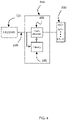
- FIG. 2 An embodiment of a vector signaling communication system with embedded clock information is shown in FIG. 2 . Elements of this system will be referenced and further described in descriptions of subsequent figures.
- the communication system of FIG. 2 consists of k distinct communication sub-systems, each comprising a history pre-coder 220, encoder 105, driver 110, n [ i ] communication wires, receiver 120, a clock-recovery unit 235, decoder 125, history post-decoder unit 245.
- Each communication sub-system i utilizes a vector signaling code in which the codewords have n [ i ] coordinates.
- bits x(0), ..., x(N-1) enter as a block into "Global Encoder" unit 205.
- this unit may only forward the bits in subgroups, while in other embodiments this unit may perform further computations on the incoming bits 200.
- Global Encoder 205 outputs k groups of bits 210, one for each of the communication sub-systems.
- the i-th group of bits 210 enters the i-th history pre-coder unit 220, which in turn outputs another group of bits 230 which is forwarded to encoder 105 of the communication sub-system.
- Encoder 105 generates a codeword of its corresponding vector signaling code, and driver 110 drives the coordinates of this codeword on the n[i] communication wires as voltages or currents.
- the communication wire voltages or currents are received as signals by receiver 120, which may perform further equalization and processing of the received signals, and may generate information for the clock-recovery unit 235 which recovers the clock information from the received signals.
- the received signals are further forwarded to decoder 125, which generates a group of bits 240 forwarded to the corresponding history post-decoder unit 245. This unit calculates a possibly new set of bits 250 and forwards these to the Global Decoder unit 260.
- Global Decoder 260 simply concatenates or combines inputs 250 to obtain output bits 270, while in other embodiments Global Decoder 260 performs additional calculations on the bits received 250 from the various history post-decoder units to re-generate the bits x(0), ..., x(N-1) output as 270.
- the number of codewords of the vector signaling codes used in the i-th communication sub-system of FIG. 2 is denoted by M(i) in the following.
- reception of distinct codewords in each unit interval provides a self-clocking capability.
- decoder 125 may consider a previous unit interval ended and a new unit interval (and thus, a new need to decode a codeword) begun each time a new (i.e., different from the preceding codeword) appears at its input.
- a codeword is transmitted on each communication sub-system that is different from the codeword sent in the previous unit interval.
- the number of possible codewords across all the communication sub-systems is M 1 ⁇ 1 * M 2 ⁇ 1 * ... * M k ⁇ 1
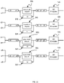
- FIG. 3 An embodiment of the history pre-coder unit 220 is shown in FIG. 3 .
- One task of this unit is to make sure that the same codeword of the vector signaling code is not sent on the corresponding communication wires (also referred to herein as a sub-channel) in two consecutive unit intervals.
- the vector signaling code receiver uses comparators for the detection of the codeword, that condition guarantees that the output of at least one of the comparators changes value from one unit interval to the next. This value change can then be used to recover the clock information, to be subsequently described in more detail.
- the history pre-coder unit comprises a pre-coder 305 and a history memory unit 320.
- the pre-coder 305 Upon receiving the block of bits b(0), ..., b(L-1) from the Global Encoder 205, the pre-coder 305 computes its output using these bits, and the history bits in 320. It forwards the resulting bits 230 to the encoder 105, and simultaneously replaces the value of the history memory 320 with these bits.
- the history memory 320 may keep the vector signaling codeword that was transmitted in the previous clock cycle and use a pre-coder which makes sure that the next transmitted codeword differs from the previous one. Such examples are given below for various types of vector signaling codes.
- FIG 4 an embodiment of the history post-decoder unit 245 is shown in FIG 4 . It comprises a post-decoder unit 405 and a history memory unit 420. Upon receiving the block 240 of bits from decoder 125, the post-decoder calculates a possibly new block of bits from the bits in 240 and the bits in its history unit 420, forwards the new bits 250 to the Global Decoder 260, and replaces the bits in its history unit with the block 240 of bits.
- FIG. 5 A flow-chart of an exemplary embodiment of the Global Encoder 205 is given in FIG. 5 .
- the main task of the Global Encoder is to compute from the given block of bits x(0), ..., x(N-1) a number k of blocks of bits, one for every communication sub-system in FIG. 2 , such that these blocks are uniquely determined by the incoming bits 200, and vice-versa. In the procedure described in FIG.
- the incoming bits x(0), ..., x(N-1) in 510 are used in Step 520 to compute bit-representations of reduced-modulus integers y(1), y(2), ..., y(k), wherein each y(i) is an integer from 0 to M(i)-2 inclusive (note that y(i) is strictly less than M(i)-1, and hence referred to herein as having a reduced-modulus), and wherein M(i) is the number of codewords of the vector signaling code used in the i-th communication sub-system in FIG. 2 .
- the digits in each position would range from 0 to M-1, where the modulus M is determined by the number of possible signals, M. That is, if there are M possible signals or codes available to represent the digits (e.g., base 10 uses ten digits: 0 through 9, and base 5 uses five digits: 0 through 4), a typical conversion might use M values: 0 to M-1. Note, however, that the conversions described herein uses digits 0 through M-2, and thus uses a reduced modulus of M-1 compared to what would normally be available with a set of M signals, or vector code codewords. The advantages of using the reduced modulus values are described below.
- FIG. 6 One embodiment of a general procedure for pre-code unit 220 is outlined in FIG. 6 . It is assumed that the bits in the history memory unit 320 of FIG. 3 represent an integer, called h, in this figure.
- the integer h is between 0 and M ( i ) - 1 , so it corresponds uniquely to a codeword of the i -th vector signaling code.
- the value of y is, by construction, smaller than M ( i ) - 1 (i.e., ⁇ M ( i ) - 2), we always have that b is not equal to h mod M ( i ) . Since h corresponds to the index of the codeword in the i -th vector signaling code transmitted in the last unit interval, and b corresponds to the index of the codeword transmitted in the current unit interval, this type of calculation makes sure that no two consecutive codewords are the same.
- the use of the reduced modulus in calculating the integers y causes the encoder to generate an output codeword that is different from the immediately prior codeword based on the reduced modulus digit (y) and the prior codeword (h).
- a subsequent codeword is selected based on h+1+y, where y is a data-dependent reduced-modulus (M-1) integer and is in the range 0 to M-2, such that no valid data-dependent reduced modulus integer will result in the subsequent codeword equaling the initial codeword h.
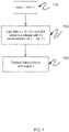
- FIG. 7 An embodiment of the operation of the post-decoder unit 245 is shown in FIG. 7 .
- the input to this procedure is a block of bits b(0), ..., b(R-1) in Step 710.
- This block may have been produced by the decoder 125 of the i-th communication sub-system illustrated in FIG. 2 .
- Step 730 the history value h is replaced by b, and simultaneously, y is forwarded to the Global Decoder 260.
- Step 820 an integer X is calculated from y(1), .., y(k) according to the formulation in (Eqn. 2).
- the bit representation of this integer is the desired sequence of bits 270 in FIG. 2 .
- the Global Encoder 205 may only forward the incoming bits in subgroups to the corresponding communication sub-systems, and the Global Decoder 260 may just collect the incoming bit blocks and concatenate them to obtain the bits 270. Some such examples are discussed further below.
- [Holden I] describes comparator-based detectors for vector signaling codes designed such that no comparator is presented with ambiguous decision conditions; that is, at all times each comparator output is either explicitly true, or explicitly false.
- An embodiment based on such codes and detectors may be combined with a simple transition detector to extract sub-system transition information (herein called the "edge signal") to drive a clock extraction circuit, as in 235 of FIG. 2 .
- Three circuits for these codes are detailed below. These are referred to in said descriptions as AH-DF-HPF, UDH-DF-HPF, and A-XOR.
- PCD-DH uses a per-codeword detector. This type of detector works with vector signaling codes in which the comparator outputs have ambiguous outputs.
- clock extraction embodiments detect changes in sub-system detector outputs. In some embodiments, only changes from one valid codeword to another valid codeword are detected, and in other embodiments decision feedback and/or hysteresis is provided to the input signal comparators to avoid extraneous transitions caused by signal reflections and noise. Any of a number of methods may then be used to analyze the edge signal to eliminate artifacts caused by near-simultaneous detector output transitions, including methods known to the art, producing a reliable sampling clock derived from the detector edges.
- One such embodiment incorporates fixed or variable delay stages and a simple state machine configured such that a clock output is produced a fixed delay time after the last edge signal transition, suppressing the effect of multiple edge signal transitions within the delay interval.
- propagation delay differences also know as skew
- propagation delay differences within a communications channel group will result in different arrival times for receive data. If the amount of this skew is significant (i.e. more than a transmit unit interval), the teachings of [Holden I] may be applied to permit the coherent reconstruction of aggregated receive data.
- a communications system utilizing multiple sub-systems may generate a global receive clock by applying the same edge signal generation and sampling clock derivation methods using the individual sub-system receive clocks as inputs, and producing a global sampling clock suitable for sampling the aggregated receive data as obtained at 270 of FIG. 2 .
- embodiments presenting significant skew between sub-system results must carefully control generation of an aggregate or global decoder output clock, such that all of the global decoder's component inputs are valid and the result meets all necessary set-up and hold times for subsequent circuits.
- Some embodiments may require intermediary holding latches on the sub-system results and/or other skew mitigation measures as taught by [Holden I] or as generally applied in practice.
- the codes and the receivers that accompany them that are used with these clocking solutions can be divided into two categories.
- the first group of codes can be described as Unambiguous Comparator Output code/receiver (UCO).
- UCO Unambiguous Comparator Output code/receiver
- the binary or multiwire comparator circuits used in the defined receiver have unambiguous outputs for every codeword in the code.
- An example of a code that is always UCO is the ENRZ code, also known as H4 code or Hadamard code of size 4, as described in [Cronie I].
- the second group of codes can be called Ambiguous Comparator Output codes/receiver (ACO).
- ACO Ambiguous Comparator Output codes/receiver
- a given comparator is sometimes presented with inputs at the same level and thus has an ambiguous output for some codewords. These ambiguous outputs are later resolved in a decoder stage.
- An example of a code that is always ACO is the 8b8w code described in Cronie II.
- codes are either UCO or ACO. There are a few codes that are ACO with one receiver implementation and UCO with another receiver implementation, typically with more complex multi-input analog detectors.
- the simplest clock extraction embodiment adds an analog hysteresis function to each of the comparators in order to filter out the multiple zero crossing on the wires that are caused by noise and reflections, as illustrated in FIG. 16 .
- the maximum amplitude of any reflections on the communications channel must be known, so that the hysteresis offset value may be chosen correctly.
- Such embodiments are known to add jitter to the recovered clock, as noise or reflections on the leading edge can cause the transition to occur early, causing the effective eye opening in the timing dimension to close, and reducing the ability of the receiver to handle difficult channels.
- the added hysteresis lowers the receive sensitivity of the comparators, reducing the eye opening in the amplitude dimension as well.
- such analog hysteresis embodiments contain a closed loop circuit that must be implemented carefully.
- HysOffset voltage value determined either statically or adaptively that exceeds the expected amplitude of reflections and other noise sources in the receive signal.
- the value "x" is shown to range from 0 to 2 for clarity. This is the case for the ENRZ code. For other UCO codes, the value that "x" would range over is equal to the number of comparators.
- the clock signal is created by using an exclusive-or function to look for changes on any of the wires.
- the code delivers a transition on one wire each clock:
- the data is delayed by a delay line that has a nominal delay of one half of the unit interval (UI).
- UI unit interval
- the actual delay would depend on the implementation and may be somewhat less or more than one half the UI:
- DFF D Flip-Flop
- An embodiment of clocking solution AH-DF-HPF shown in FIG. 17 performs six additional binary comparisons, such that two values of a hysteresis comparison is provided along with each data comparison.
- This embodiment has the advantage that the closed loop portion of the hysteresis function is digital, and the data path portion of the circuit has better sensitivity than AH-DF-HPF.
- the disadvantages include greater implementation size and higher power consumption, because of the additional comparators needed to produce the required hysteresis comparisons.
- One embodiment uses two extra separate comparators that add and subtract a fixed value from the analog inputs, rather than using analog hysteresis feedback.
- the hysteresis function may then be implemented digitally.
- Another embodiment uses a combined comparator that delivers three outputs, the regular comparator output, an output with the comparison done with the offset added, and a third with the comparison done with the offset subtracted.
- comparators are:
- Clock ((NOT Q(0)) AND CompOutHigh(0)) OR (Q(0) AND (NOT CompOutLow(0))) OR ((NOT Q(1)) AND CompOutHigh(1)) OR (Q(1) AND (NOT CompOutLow(1)) OR ((NOT Q(2)) AND CompOutHigh(2)) OR (Q(2) AND (NOT CompOutLow(2)))
- the rest is the same as in the AH-DF-HPF embodiment.
- FIG. 18 An embodiment of clock extraction using Analog XOR clocking is shown in FIG. 18 . This embodiment is compatible with both UCO and ACO code/receiver solutions.
- Each comparator function is divided into two halves.
- the first half of each comparator is a linear low gain comparator that performs the function of the comparator with a linear output.
- Each of these linear values is then passed through an analog low-pass filter.
- Each linear value is compared against the analog low-pass filtered version of itself by an analog XOR circuit, which serves as the second half of the comparison function.
- Analog XOR circuits are well known in the art. The analog XOR circuit will produce a voltage output that has a higher value if the inputs have different values than if they have the same value.
- the outputs of the three analog XOR circuits are summed.
- the output of the summer is passed through a limiting gain stage to give the signal sharp edges. This signal then forms the clock.
- the output of the low gain comparator is passed through a gain stage to form a regular binary comparator.
- the clock is used to sample this data.
- a challenge with this circuit is that the detected change is less for some code transitions than for others.
- This circuit is also sensitive to reflections and noise.
- This embodiment is compatible with both UCO and ACO code/receiver solutions.
- this embodiment of a clock extraction circuit does not use an analog hysteresis circuit. Instead it uses normal comparators 1910.
- a special unrolled and equal-delay digital detector is implemented that has one output for each of the allowed codewords.
- the circuit is implemented to have a roughly equal delay from the output of each of the comparators to the output of each of the per-codeword detector.
- An example of such an equal-delay circuit is a circuit that has a AND gate 1920 per codeword. That AND gate has the same number of legs as the number of comparators. The inputs of the legs of the AND gates are wired to the appropriate true or complement outputs of the comparators, here shown distinct true and complimentary inputs to each AND gate 1920.
- the particular decoded values shown are exemplary, and non-limiting.
- the per-codeword detectors are only connected to those comparator outputs that are needed to detect that codeword and not to those that have an ambiguous value for that codeword.
- each of the per-codeword detectors is wired to the Set input of a per-codeword Resettable D Flip-Flop with the D input set to a high value (or equivalent circuit.)
- the flip-flops 1930 are shown in FIG. 19 as edge triggered set/reset devices, with the output Q going true on a rising edge of input S, and going false on a rising edge of input R.
- any detected codeword by AND gates 1920 will cause the corresponding flip-flop 1930 to set.
- the outputs of all of these Flip-Flops 1930 are ORed together 1940 and delayed by a delay line 1950 that is statically or dynamically calibrated to create a rising edge in the middle of the data eye.
- Said rising edge signal is used as the clock in a data re-timer circuit.
- Said rising edge signal is also connected to the Reset input of each flip-flop 1930 to clear the detectors for the next clock cycle.
- the described embodiment will catch the first instance within a clock cycle of a codeword being detected and will ignore subsequent reflections that cause zero-crossings.
- DRAM Dynamic Random Access Memory
- the number of vector signaling codewords in these applications has to satisfy the inequality 257 ⁇ M 1 ⁇ 1 ⁇ ... ⁇ M k ⁇ 1 as 256 distinct codewords are required to communicate 8 bits of data, and at least a 257th codeword is required to communicate the notification provided by the write mask signal that this data byte is to be ignored for this memory operation.
- the resulting embodiment is hereinafter called ENRZ3, referring to its three sub-systems, each utilizing ENRZ vector signaling code.
- the input to the Global Encoder consists of 9 bits x0, x1, ..., x8 corresponding to an integer between 0 and 256 inclusive (that is, 257 distinct values.)
- the Global Encoder may have an implementation as previously described in FIG. 5 . It produces 3 groups of 3 bits, called ( a 0 , a 1 , a 2) , ( b 0 , b 1 , b 2) , and ( c 0 , c 1 , c 2) , one group of bits for each ENRZ sub-system. Each of these vectors corresponds to the bit-representation of an integer modulo 7. This means that none of these vectors consists of three 1's.
- the history units 320 each contain 3 bits corresponding to the bit sequences transmitted in the previous unit interval, and called respectively h 0 , h 1 , and h 2 .
- the pre-coding units 305 used in this example operate differently than the general pre-coding units described in FIG. 6 , as the particular input characteristics permit simplification.
- each pre-coding unit computes the XOR of the complement of the inputs 210 from the Global Encoder 205, with its corresponding history bits. Since none of the vectors 210 consists entirely of 1's, the complement of none of these vectors consists entirely of 0's, and hence the operation of the pre-coding unit ensures that the result of the operation is always different from the bits in the corresponding history units 320.
- Each of the pre-coding units forwards the computed bits to the corresponding ENRZ encoders 105, and simultaneously replaces the history bits with these bits.
- Each communication sub-system in this embodiment transmits 3 bits on its corresponding 4-wire interface. The number of wires is therefore 12.
- Each sub-system uses 3 multi-input comparators (also known as generalized comparators, as described in [Holden I]) to recover its bits. The output of these comparators can be used to do a clock recovery on every one of the sub-systems, according to the teachings above. There are therefore a total of 9 comparators.
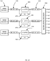
- FIG. 10 is an exemplary embodiment of the receiver portion of the decoder for this communication system.
- the ENRZ decoders 125 forward a group 240 of three bits each to the post-decoder units 405. These units XOR the incoming bits with the 3 bits in their history units 420, complement the result, and forward it to the Global Decoder 260. Simultaneously, they replace their three history bits with the forwarded bits.
- the operation of the Global Decoder 260 in this embodiment may be as described in FIG. 8 .
- the ISI ratio of this coding system is 1, which is the lowest ISI ratio possible. This means that this coding system has a low susceptibility to ISI noise.
- This communication system uses 12 signal wires, and 9 comparators. To enable operation at high data rates, the wires have to be routed in 3 low-skew groups of 4 wires each.
- S3 is a vector signaling code on three wires consisting of the 6 permutations of the vector (+1,0,-1).
- k 4 corresponding to four communication sub-systems in FIG. 2
- S34 referring to its four sub-systems, each utilizing S3 vector signaling code. This coding scheme is similar to the one reported in [Wiley], though the details of the encoding and decoding are different.
- FIG. 11 An embodiment of the encoder is detailed in FIG. 11 .
- the incoming bits are subdivided into three groups (x0, x1), (x2, x3), (x4, x5) of two bits, and (x6, x7, x8) of three bits. Because of the restriction of the input bits, the fourth group corresponds to an integer between 0 and 4, inclusive.
- the history units 320 each contain 3 bits corresponding to the bit sequences transmitted in the previous unit interval, and can be viewed as integers modulo 6, and called h0, h1, h2, and h3, respectively.
- the pre-coding units 305 operate as described in FIG. 6 . Each of the pre-coding units forwards the computed bits to the corresponding S3 encoders 105, and simultaneously replaces the history bits with these bits.
- Each communication sub-system in this example transmits two or more bits on its corresponding 3-wire interface using ternary signaling.
- the encoders 105 may conveniently represent their ternary output by generating two bit vectors of length 3 such that each bit vector has exactly one "1", and the positions of the 1's in these vectors are disjoint.
- the first bit vector may encode the position of the +1 in the vector signaling codes S3, and the second bit vector may encode the position of the -1, in the sense that a +1 is transmitted on the wire where the first bit vector is 1, a -1 is transmitted on the wire where the second bit vector is 1, and a 0 is transmitted on the wire if neither bit vector is 1.
- the described bit vectors may be used to drive transistors in an output line driver generating the desired +1 and -1 output signal values.
- FIG. 12 An example of the operation of such an encoder is described in FIG. 12 , showing two logical circuits as FIG. 12A and FIG. 12B .
- the inputs to these circuits are three incoming bits a,b,c corresponding to an integer between 0 and 5, inclusive, where a is the least and c is the most significant bit of the integer.
- the circuit of FIG. 12A does not, in fact, use the input a, and computes its three outputs as NOR(b,c), b, and c. In operation, the output of this circuit may be interpreted as a mask for the position of +1 in the codeword of S3 chosen to be transmitted.
- FIG. 13 An exemplary embodiment of decoder 125 of FIG. 1 for the case of S3 coding is given in FIG. 13 .
- the three communication wires S3D01, S3D02, S3D03 enter a network of comparators S3D20, S3D25, and S3D30.
- S3D20 produces an output of "0" if the value on wire S3D01 is larger than the value on wire S3D02, and otherwise the output is 1.
- Decoder 125 is a circuit that computes as its first output the value B&C, as its second output the value A ⁇ B ⁇ C, and on its third output the value A&( ⁇ C), wherein A, B, and C are the outputs of units S3D20, S3D25, and S3D30, respectively.
- the post-decoder units in this embodiment operate as described in FIG. 7 . No explicit Global Decoder is required, as the bits output by the post-decoder units may simply be concatenated together to re-create the output bits 270 of FIG.2 .
- the ISI ratio of this coding system is 2. This means that this coding system has a higher susceptibility to ISI noise than the ENRZ3 scheme.
- This communication system uses 12 signal wires, and 12 comparators. The wires have to be routed in 4 low-skew groups of 3 wires each.
- the S4 code is a vector signaling code on four wires consisting of the 12 distinct permutations of the vector (+1, 0, 0, -1). This code can be detected using six pairwise comparators. The ISI ratio of this code is 2.
- the P3 code is a vector signaling code on three wires consisting of the four codewords (1, 0, -1), (-1, 0, 1), (0, 1, -1), and (0, -1, 1).
- the codewords can be detected using the comparators x-y and (x+y)/2-z on the received signals (x,y,z) on the three wires.
- the ISI ratio of this code is 1.
- the Global Encoder 205 of FIG. 2 , and the Global Decoder 260 of FIG. 2 can operate according to the procedures in FIG. 5 and FIG. 8 , respectively.
- the history pre-coding and post-decoding units 220 and 245 may also operate according to the procedures in FIG. 3 and FIG. 4 , respectively.
- FIG. 14 One embodiment of an encoder for the S4 code is given in FIG. 14 .
- the encoder produces two bit-vector (p0, p1, p2, p3) through the upper circuit and (m0, m1, m2, m3) through the lower circuit from inputs a,b,c,d representing an integer between 0 and 11 inclusive, wherein a is the least and d is the most significant bit of this integer.
- the bit sequence (p0, p1, p2, p3) is a mask for the position of the +1 in the corresponding codewords of S3, and (m0, m1, m2, m3) is a mask for the position of -1 in that codeword.
- FIG. 15 One embodiment of an encoder for the code P3 is given in FIG. 15 . Similar to the encoder for S4, this encoder produces two bit-vectors (p0, p1) and (m0, m1) from its inputs a and b. These vectors are masks for the positions of +1 and -1, respectively, in the corresponding codeword of P3.
- the ISI ratio of this coding system is 2. This means that this coding system has a higher susceptibility to ISI noise than the ENRZ3 scheme, but a similar susceptibility to ISI noise as S34. This is confirmed by statistical simulation results reported below.
- This communication system uses 11 signal wires, and 14 comparators.
- the wires have to be routed in 2 low-skew groups of 4 wires and one low-skew group of 3 wires each.
- OCT is a vector signaling code on three wires consisting of the 8 codewords ((0.6, -1, 0.4), ((-0.2, -0.8, 1), ((-0.8, -0.2, 1), ((1, -0.6, -0.4).
- This code can be detected using four comparators x-y, (x+2 ⁇ z)/3-y, (y+2 ⁇ z)/3-x, (x+y)/2-1 on input (x,y,z) which represent the received values on the three wires of the interface. This code was first described in [Shokrollahi I].
- Global Encoder 205 of FIG.2 and the Global Decoder 260 of FIG. 2 operate according to the procedures in FIG. 5 and FIG. 8 , respectively, and the history pre-coding and post-decoding units 220 and 245 operate according to the procedures in FIG. 3 and FIG. 4 , respectively.
- pre-coding 220 and post-decoding 245 units operate according to the procedure outlined for ENRZ3 in FIG. 9 and FIG. 10 , respectively.
- the ISI ratio of this coding system is 8/3. This means that this coding system has a higher susceptibility to ISI noise all the previous systems. This is confirmed by statistical simulation results reported below.
- This communication system uses 9 signal wires, and 12 comparators. The wires have to be routed in 3 low-skew groups of 3 wires each.
- the code C18 is a vector signaling code on four wires consisting of the 18 codewords
- This code can be detected using five comparators x-z, x-u, y-z, y-u, z-u on input (x,y,z,u) which represent the received values on the four wires of the interface. This code was first disclosed in [Shokrollahi II].
- This communication system can be made to work without a global encoder or a global decoder unit.
- the history pre-coding 220 and post-decoding 245 units may operate according to the procedures in FIG. 3 and FIG. 4 , respectively.
- the ISI ratio of this coding system is 3. This means that this coding system has a higher susceptibility to ISI noise all the previous systems. This is confirmed by statistical simulation results reported below.
- This communication system uses 8 signal wires, and 10 comparators. The wires have to be routed in 2 low-skew groups of 4 wires each.
- the peak-to-peak voltage between the top and low levels was chosen to be 200mV, and a channel model was used that is based on conventional communications channel characteristics for microstrips routed between integrated circuit devices.
- the only equalization used is a Tx FIR with one pre- and one post-cursor.
- the channel represents a realistic mobile DRAM channel, operating at a signaling rate of 7 GBaud/second, with the interfaces transmitting one full byte (plus mask) in every unit interval.
- the total throughput is therefore 56 Gbps.
- the minimal horizontal eye opening is a decreasing function of the ISI ratio.
- Higher crosstalk and lower margin further reduces the vertical opening for all codes other than ENRZ3.
- the coding functions are divided into open-loop and closed-loop portions.
- the goal of such a division is to make the closed-loop portion as small as possible in order to allow it to run at the highest speed possible.
- the closed loop portion works with historical information of what was sent on the line.
- said closed-loop circuit works with the sample from the previous clock time.
- the open-loop portion of the circuit does not work on historical information from the line.
- an embodiment incorporating multiple instantiations of the circuit can be implemented in parallel, as illustrated in the example transmit encoding function shown in FIG. 21 and the example receive decoding function shown in FIG. 23 ..
- This is often referred to as a multi-phase circuit because the said parallel circuits are fed their inputs and produce their outputs offset in time from the other parallel circuits, e.g. in different circuit phases.
- This parallel operation allows said open-loop encode circuit to have a markedly higher effective throughput.
- the outputs of said parallel circuits are then multiplexed back together into one output that said closed-loop encode circuit can operate on.
- the operation that said parallel open-loop encode circuit must perform is to break down the data input b(0) through b(L-1) into chunks that have M(K) - 1 states.
- the operation that said closed-loop encode circuit must perform is to compare the vector with the last vector that was sent. If said vectors are the same, the vector is replaced by the pre-defined repeat code.
- the operation that said closed-loop decode circuit must perform is to compare the vector received with the repeat code. If said vectors are the same, said vector is then replaced by the vector that had been received immediately prior to the repeat code.
- the operation that said parallel open-loop decode circuit must perform is to reassemble the vectors that have M(K) - 1 states back into the data output of b(0) through b(L-1).
Claims (15)
- Vorrichtung, umfassend:zwei oder mehr Empfängersubsysteme (120), wobei jedes Empfängersubsystem umfasst:eine Empfangsschaltung, die dafür konfiguriert ist, Symbole eines Codewortes eines Vektorsignalisierungscodes auf einem jeweiligen Empfangssubkanal zu empfangen, wobei jeder Empfangssubkanal eine Vielzahl von Signalleitungen umfasst, wobei in jeglichem benachbarten Signalisierungsintervall empfangene Codewörter unterschiedlich sind;einen Datendecodierer (125), der dafür konfiguriert ist, die empfangenen Symbole des Codewortes zu einem Satz von Bits zu decodieren;einen Datenhistorien-Nachdecodierer (245), der dafür konfiguriert ist, den Satz von Bits zu empfangen und empfangene Subsystemdaten mit reduziertem Modul auf Basis des empfangenen Satzes von Bits und eines Satzes vorheriger empfangener Bits zu erzeugen; undeinen globalen Decodierer (260), der dafür konfiguriert ist, die empfangenen Subsystemdaten mit reduziertem Modul aus jedem der zwei oder mehr Empfängersubsysteme zu empfangen und die empfangenen Subsystemdaten mit reduziertem Modul zu einem Satz von Ausgangsdaten zu rekonstruieren.
- Vorrichtung nach Anspruch 1, wobei jedes Empfängersubsystem (120) ferner eine Taktextraktionsschaltung (235) umfasst, die dafür konfiguriert ist, ein Taktsignal auf Basis von Symbolübergängen zwischen in benachbarten Signalisierungsintervallen empfangenen Codewörtern zu erhalten.
- Vorrichtung nach Anspruch 2, wobei die Taktextraktionsschaltung (235) Offsetkomparatoren umfasst, die konfiguriert sind zum Addieren und Subtrahieren fester Werte von den empfangenen Symbolen des Codewortes.
- Vorrichtung nach Anspruch 2, wobei die Taktextraktionsschaltung (235) einen kombinierten Komparator umfasst, der dafür konfiguriert ist, drei Komparatorausgänge zu liefern: einen regulären Komparatorausgang, einen Ausgang mit einem addierten Offset und einen Ausgang mit einem subtrahierten Offset, wobei die Taktextraktionsschaltung das Taktsignal auf Basis der drei Komparatorausgänge erhält.
- Vorrichtung nach Anspruch 2, wobei jede Empfangsschaltung dafür konfiguriert ist, lineare Werte zu generieren, die mit jedem empfangenen Codewort assoziiert sind, und wobei jede jeweilige Taktextraktionsschaltung (235) einen Tiefpassfilter, der dafür konfiguriert ist, eine analoge tiefpassgefilterte Version jedes linearen Wertes zu generieren, und eine analoge XOR-Schaltung, die dafür konfiguriert ist, jeden linearen Wert mit der analogen tiefpassgefilterten Version von sich selbst zu vergleichen, umfasst, und wobei die Vorrichtung ferner einen Summierer umfasst, der dafür konfiguriert ist, Ausgänge jeder analogen XOR-Schaltung zu summieren, um das Taktsignal zu generieren.
- Vorrichtung nach Anspruch 2, wobei die Taktextraktionsschaltung (235) pro-Codewort-Flipflops umfasst, wobei jedes pro-Codewort-Flipflop mit einem Ausgang eines jeweiligen pro-Codewort-AND-Gatters verbunden ist und wobei die Ausgänge der pro-Codewort-Flipflops unter Verwendung einer OR-Schaltung miteinander kombiniert und durch eine Verzögerungsleitungsschaltung hindurchgeführt werden.
- Vorrichtung nach Anspruch 1, wobei der globale Decodierer (260) dafür konfiguriert ist, eine komplementäre Berechnung an den empfangenen Subsystemdaten mit reduziertem Modul durchzuführen, um den Satz von Ausgangsdaten zu erhalten.
- Vorrichtung nach Anspruch 1, wobei der globale Decodierer (260) konfiguriert ist zum Verketten der empfangenen Subkanaldaten mit reduziertem Modul, die aus jedem Empfängersubsystem empfangen werden, um den Satz von Ausgangsdaten zu generieren.
- Verfahren, umfassend:Empfangen, über zwei oder mehr Empfängersubsysteme (120), eines jeweiligen Satzes von Symbolen eines Codewortes eines Vektorsignalisierungscodes auf einem jeweiligen Empfangssubkanal, wobei jeder Empfangssubkanal eine Vielzahl von Signalleitungen umfasst, wobei in jeglichem benachbarten Signalisierungsintervall empfangene Codewörter unterschiedlich sind;Decodieren, an einem jeweiligen Datendecodierer (125), jedes jeweiligen empfangenen Symbols des Codewortes zu einem jeweiligen Satz von Bits;Empfangen, an einem jeweiligen Datenhistorien-Nachdecodierer (245), des jeweiligen Satzes von Bits und Erzeugen jeweiliger empfangener Subsystemdaten mit reduziertem Modul auf Basis des jeweiligen Satzes von Bits und eines jeweiligen Satzes vorheriger empfangener Bits; undRekonstituieren, an einem globalen Decodierer (260), aller jeweiligen empfangenen Subsystemdaten mit reduziertem Modul aus jedem der zwei oder mehr Empfängersubsysteme zu einem Satz von Ausgangsdaten.
- Verfahren nach Anspruch 9, ferner umfassend das Erhalten eines jeweiligen Taktsignals für jedes Empfängersubsystem (120) auf Basis von Symbolübergängen zwischen in benachbarten Signalisierungsintervallen in dem Empfängersubsystem empfangenen Codewörtern.
- Verfahren nach Anspruch 10, wobei das Erhalten des Taktsignals das Herausfiltern von Nulldurchgängen auf jeder Signalleitung der Vielzahl von Signalleitungen, die durch Rauschen und/oder Reflexionen verursacht werden, unter Verwendung jeweiliger analoger Hystereseschaltungen und unter Verwendung jeweiliger Exklusiv-OR-Funktionen zum Detektieren der Symbolübergänge auf einer beliebigen der Signalleitungen der Vielzahl von Signalleitungen umfasst.
- Verfahren nach Anspruch 10, wobei das Erhalten des Taktsignals das Addieren und Subtrahieren fester Werte von dem jeweiligen Satz von empfangenen Symbolen des Codewortes unter Verwendung von Offsetkomparatoren umfasst.
- Verfahren nach Anspruch 10, wobei das Erhalten des Taktsignals die Verwendung von Pro-Codewort-Flipflops umfasst, wobei jedes pro-Codewort-Flipflop mit einem Ausgang eines entsprechenden pro-Codewort-AND-Gatters verbunden ist und wobei die Ausgänge des pro-Codewort-Flipflops miteinander OR-kombiniert und durch eine Verzögerungsleitungsschaltung hindurchgeführt werden.
- Verfahren nach Anspruch 9, ferner umfassend das Durchführen einer komplementären Berechnung an allen jeweiligen empfangenen Subsystemdaten mit reduziertem Modul, um den Satz von Ausgangsdaten zu erhalten.
- Verfahren nach Anspruch 9, ferner umfassend das Verketten aller empfangenen Subkanaldaten mit reduziertem Modul, die aus jedem Empfängersubsystem (120) empfangen werden, um den Satz von Ausgabedaten zu generieren.
Applications Claiming Priority (3)
| Application Number | Priority Date | Filing Date | Title |
|---|---|---|---|
| US201461946574P | 2014-02-28 | 2014-02-28 | |
| EP15710999.2A EP3111607B1 (de) | 2014-02-28 | 2015-03-02 | Vektorsignalisierungskodes mit eingebettetem takt |
| PCT/US2015/018363 WO2015131203A1 (en) | 2014-02-28 | 2015-03-02 | Clock-embedded vector signaling codes |
Related Parent Applications (2)
| Application Number | Title | Priority Date | Filing Date |
|---|---|---|---|
| EP15710999.2A Division EP3111607B1 (de) | 2014-02-28 | 2015-03-02 | Vektorsignalisierungskodes mit eingebettetem takt |
| EP15710999.2A Division-Into EP3111607B1 (de) | 2014-02-28 | 2015-03-02 | Vektorsignalisierungskodes mit eingebettetem takt |
Publications (2)
| Publication Number | Publication Date |
|---|---|
| EP3672176A1 EP3672176A1 (de) | 2020-06-24 |
| EP3672176B1 true EP3672176B1 (de) | 2022-05-11 |
Family
ID=52693057
Family Applications (2)
| Application Number | Title | Priority Date | Filing Date |
|---|---|---|---|
| EP20155839.2A Active EP3672176B1 (de) | 2014-02-28 | 2015-03-02 | Vektorsignalisierungskodes mit eingebettetem takt |
| EP15710999.2A Active EP3111607B1 (de) | 2014-02-28 | 2015-03-02 | Vektorsignalisierungskodes mit eingebettetem takt |
Family Applications After (1)
| Application Number | Title | Priority Date | Filing Date |
|---|---|---|---|
| EP15710999.2A Active EP3111607B1 (de) | 2014-02-28 | 2015-03-02 | Vektorsignalisierungskodes mit eingebettetem takt |
Country Status (5)
| Country | Link |
|---|---|
| US (5) | US9363114B2 (de) |
| EP (2) | EP3672176B1 (de) |
| KR (1) | KR102240544B1 (de) |
| CN (1) | CN106105123B (de) |
| WO (1) | WO2015131203A1 (de) |
Families Citing this family (53)
| Publication number | Priority date | Publication date | Assignee | Title |
|---|---|---|---|---|
| US9288089B2 (en) | 2010-04-30 | 2016-03-15 | Ecole Polytechnique Federale De Lausanne (Epfl) | Orthogonal differential vector signaling |
| US9288082B1 (en) | 2010-05-20 | 2016-03-15 | Kandou Labs, S.A. | Circuits for efficient detection of vector signaling codes for chip-to-chip communication using sums of differences |
| US9251873B1 (en) | 2010-05-20 | 2016-02-02 | Kandou Labs, S.A. | Methods and systems for pin-efficient memory controller interface using vector signaling codes for chip-to-chip communications |
| US9077386B1 (en) | 2010-05-20 | 2015-07-07 | Kandou Labs, S.A. | Methods and systems for selection of unions of vector signaling codes for power and pin efficient chip-to-chip communication |
| US9246713B2 (en) | 2010-05-20 | 2016-01-26 | Kandou Labs, S.A. | Vector signaling with reduced receiver complexity |
| US9124557B2 (en) | 2010-05-20 | 2015-09-01 | Kandou Labs, S.A. | Methods and systems for chip-to-chip communication with reduced simultaneous switching noise |
| US9985634B2 (en) | 2010-05-20 | 2018-05-29 | Kandou Labs, S.A. | Data-driven voltage regulator |
| US9268683B1 (en) | 2012-05-14 | 2016-02-23 | Kandou Labs, S.A. | Storage method and apparatus for random access memory using codeword storage |
| WO2014124450A1 (en) | 2013-02-11 | 2014-08-14 | Kandou Labs, S.A. | Methods and systems for high bandwidth chip-to-chip communications interface |
| KR102241045B1 (ko) | 2013-04-16 | 2021-04-19 | 칸도우 랩스 에스에이 | 고 대역폭 통신 인터페이스를 위한 방법 및 시스템 |
| WO2014210074A1 (en) | 2013-06-25 | 2014-12-31 | Kandou Labs SA | Vector signaling with reduced receiver complexity |
| US9806761B1 (en) | 2014-01-31 | 2017-10-31 | Kandou Labs, S.A. | Methods and systems for reduction of nearest-neighbor crosstalk |
| EP3100424B1 (de) | 2014-02-02 | 2023-06-07 | Kandou Labs S.A. | Verfahren und vorrichtung für chip-to-chip-kommunikationen mit niedriger leistungsaufnahme mit eingeschränktem isi-verhältnis |
| EP3672176B1 (de) | 2014-02-28 | 2022-05-11 | Kandou Labs, S.A. | Vektorsignalisierungskodes mit eingebettetem takt |
| US11240076B2 (en) | 2014-05-13 | 2022-02-01 | Kandou Labs, S.A. | Vector signaling code with improved noise margin |
| US9509437B2 (en) | 2014-05-13 | 2016-11-29 | Kandou Labs, S.A. | Vector signaling code with improved noise margin |
| US9852806B2 (en) | 2014-06-20 | 2017-12-26 | Kandou Labs, S.A. | System for generating a test pattern to detect and isolate stuck faults for an interface using transition coding |
| US9112550B1 (en) | 2014-06-25 | 2015-08-18 | Kandou Labs, SA | Multilevel driver for high speed chip-to-chip communications |
| CN106797352B (zh) | 2014-07-10 | 2020-04-07 | 康杜实验室公司 | 高信噪特性向量信令码 |
| US9432082B2 (en) | 2014-07-17 | 2016-08-30 | Kandou Labs, S.A. | Bus reversable orthogonal differential vector signaling codes |
| WO2016014423A1 (en) | 2014-07-21 | 2016-01-28 | Kandou Labs S.A. | Multidrop data transfer |
| KR101949964B1 (ko) | 2014-08-01 | 2019-02-20 | 칸도우 랩스 에스에이 | 임베딩된 클록을 갖는 직교 차동 벡터 시그널링 코드 |
| US9674014B2 (en) | 2014-10-22 | 2017-06-06 | Kandou Labs, S.A. | Method and apparatus for high speed chip-to-chip communications |
| KR102372931B1 (ko) | 2015-06-26 | 2022-03-11 | 칸도우 랩스 에스에이 | 고속 통신 시스템 |
| US9984035B2 (en) | 2015-08-27 | 2018-05-29 | Qualcomm Incorporated | Efficient encoding and decoding architecture for high-rate data transfer through a parallel bus |
| US10055372B2 (en) * | 2015-11-25 | 2018-08-21 | Kandou Labs, S.A. | Orthogonal differential vector signaling codes with embedded clock |
| US10003315B2 (en) | 2016-01-25 | 2018-06-19 | Kandou Labs S.A. | Voltage sampler driver with enhanced high-frequency gain |
| CN115085727A (zh) | 2016-04-22 | 2022-09-20 | 康杜实验室公司 | 高性能锁相环 |
| US10003454B2 (en) | 2016-04-22 | 2018-06-19 | Kandou Labs, S.A. | Sampler with low input kickback |
| EP3449606A4 (de) | 2016-04-28 | 2019-11-27 | Kandou Labs S.A. | Mehrstufiger treiber mit geringem stromverbrauch |
| WO2017189931A1 (en) * | 2016-04-28 | 2017-11-02 | Kandou Labs, S.A. | Vector signaling codes for densely-routed wire groups |
| US10153591B2 (en) | 2016-04-28 | 2018-12-11 | Kandou Labs, S.A. | Skew-resistant multi-wire channel |
| US9906358B1 (en) | 2016-08-31 | 2018-02-27 | Kandou Labs, S.A. | Lock detector for phase lock loop |
| US10411922B2 (en) | 2016-09-16 | 2019-09-10 | Kandou Labs, S.A. | Data-driven phase detector element for phase locked loops |
| US10200188B2 (en) | 2016-10-21 | 2019-02-05 | Kandou Labs, S.A. | Quadrature and duty cycle error correction in matrix phase lock loop |
| US10372665B2 (en) | 2016-10-24 | 2019-08-06 | Kandou Labs, S.A. | Multiphase data receiver with distributed DFE |
| US10200218B2 (en) | 2016-10-24 | 2019-02-05 | Kandou Labs, S.A. | Multi-stage sampler with increased gain |
| WO2018191749A1 (en) | 2017-04-14 | 2018-10-18 | Kandou Labs, S.A. | Pipelined forward error correction for vector signaling code channel |
| DE112018002643T5 (de) | 2017-05-22 | 2020-05-07 | Invention Mine, Llc | Multimodale datengetriebene taktwiederherstellungsschaltung |
| US10116468B1 (en) | 2017-06-28 | 2018-10-30 | Kandou Labs, S.A. | Low power chip-to-chip bidirectional communications |
| US10686583B2 (en) | 2017-07-04 | 2020-06-16 | Kandou Labs, S.A. | Method for measuring and correcting multi-wire skew |
| US10693587B2 (en) | 2017-07-10 | 2020-06-23 | Kandou Labs, S.A. | Multi-wire permuted forward error correction |
| US10203226B1 (en) | 2017-08-11 | 2019-02-12 | Kandou Labs, S.A. | Phase interpolation circuit |
| US10256795B1 (en) * | 2017-10-11 | 2019-04-09 | Micron Technology, Inc. | Pipelined latches to prevent metastability |
| US10326623B1 (en) | 2017-12-08 | 2019-06-18 | Kandou Labs, S.A. | Methods and systems for providing multi-stage distributed decision feedback equalization |
| US10467177B2 (en) | 2017-12-08 | 2019-11-05 | Kandou Labs, S.A. | High speed memory interface |
| WO2019133897A1 (en) | 2017-12-28 | 2019-07-04 | Kandou Labs, S.A. | Synchronously-switched multi-input demodulating comparator |
| US10243614B1 (en) | 2018-01-26 | 2019-03-26 | Kandou Labs, S.A. | Method and system for calibrating multi-wire skew |
| US10554380B2 (en) | 2018-01-26 | 2020-02-04 | Kandou Labs, S.A. | Dynamically weighted exclusive or gate having weighted output segments for phase detection and phase interpolation |
| US11088878B2 (en) * | 2020-01-03 | 2021-08-10 | Korea University Research And Business Foundation | Transceiver using multi-level braid signaling and method of operating the same |
| US20210342285A1 (en) * | 2020-04-30 | 2021-11-04 | Advanced Micro Devices, Inc. | Encoding of symbols for a computer interconnect based on frequency of symbol values |
| US11545980B1 (en) * | 2021-09-08 | 2023-01-03 | Qualcomm Incorporated | Clock and data recovery for multi-phase, multi-level encoding |
| WO2024049482A1 (en) | 2022-08-30 | 2024-03-07 | Kandou Labs SA | Pre-scaler for orthogonal differential vector signalling |
Family Cites Families (455)
| Publication number | Priority date | Publication date | Assignee | Title |
|---|---|---|---|---|
| US668687A (en) | 1900-12-06 | 1901-02-26 | Louis G Mayer | Thill-coupling. |
| US780883A (en) | 1903-11-18 | 1905-01-24 | Mortimer Livingston Hinchman | Advertising device. |
| US3196351A (en) | 1962-06-26 | 1965-07-20 | Bell Telephone Labor Inc | Permutation code signaling |
| US3636463A (en) | 1969-12-12 | 1972-01-18 | Shell Oil Co | Method of and means for gainranging amplification |
| US3939468A (en) | 1974-01-08 | 1976-02-17 | Whitehall Corporation | Differential charge amplifier for marine seismic applications |
| US3970795A (en) | 1974-07-16 | 1976-07-20 | The Post Office | Measurement of noise in a communication channel |
| JPS5279747A (en) | 1975-12-26 | 1977-07-05 | Sony Corp | Noise removal circuit |
| US4206316A (en) | 1976-05-24 | 1980-06-03 | Hughes Aircraft Company | Transmitter-receiver system utilizing pulse position modulation and pulse compression |
| US4181967A (en) | 1978-07-18 | 1980-01-01 | Motorola, Inc. | Digital apparatus approximating multiplication of analog signal by sine wave signal and method |
| US4276543A (en) | 1979-03-19 | 1981-06-30 | Trw Inc. | Monolithic triple diffusion analog to digital converter |
| US4486739A (en) | 1982-06-30 | 1984-12-04 | International Business Machines Corporation | Byte oriented DC balanced (0,4) 8B/10B partitioned block transmission code |
| US4499550A (en) | 1982-09-30 | 1985-02-12 | General Electric Company | Walsh function mixer and tone detector |
| US4722084A (en) | 1985-10-02 | 1988-01-26 | Itt Corporation | Array reconfiguration apparatus and methods particularly adapted for use with very large scale integrated circuits |
| US4772845A (en) | 1987-01-15 | 1988-09-20 | Raytheon Company | Cable continuity testor including a sequential state machine |
| US4864303A (en) | 1987-02-13 | 1989-09-05 | Board Of Trustees Of The University Of Illinois | Encoder/decoder system and methodology utilizing conservative coding with block delimiters, for serial communication |
| US4774498A (en) | 1987-03-09 | 1988-09-27 | Tektronix, Inc. | Analog-to-digital converter with error checking and correction circuits |
| US5053974A (en) | 1987-03-31 | 1991-10-01 | Texas Instruments Incorporated | Closeness code and method |
| US4897657A (en) | 1988-06-13 | 1990-01-30 | Integrated Device Technology, Inc. | Analog-to-digital converter having error detection and correction |
| US7421633B2 (en) | 2005-03-21 | 2008-09-02 | Texas Instruments Incorporated | Controller receiving combined TMS/TDI and suppyling separate TMS and TDI |
| US4974211A (en) | 1989-03-17 | 1990-11-27 | Hewlett-Packard Company | Digital ultrasound system with dynamic focus |
| US5168509A (en) | 1989-04-12 | 1992-12-01 | Kabushiki Kaisha Toshiba | Quadrature amplitude modulation communication system with transparent error correction |
| FR2646741B1 (fr) | 1989-05-03 | 1994-09-02 | Thomson Hybrides Microondes | Echantillonneur-bloqueur a haute frequence d'echantillonnage |
| US5172280A (en) | 1989-10-26 | 1992-12-15 | Archive Corporation | Apparatus and method for automatic write current calibration in a streaming tape drive |
| US5599550A (en) | 1989-11-18 | 1997-02-04 | Kohlruss; Gregor | Disposable, biodegradable, wax-impregnated dust-cloth |
| US5166956A (en) | 1990-05-21 | 1992-11-24 | North American Philips Corporation | Data transmission system and apparatus providing multi-level differential signal transmission |
| US5266907A (en) | 1991-06-25 | 1993-11-30 | Timeback Fll | Continuously tuneable frequency steerable frequency synthesizer having frequency lock for precision synthesis |
| US5287305A (en) | 1991-06-28 | 1994-02-15 | Sharp Kabushiki Kaisha | Memory device including two-valued/n-valued conversion unit |
| EP0543070A1 (de) | 1991-11-21 | 1993-05-26 | International Business Machines Corporation | Codierungsystem und -Verfahren, das quaternäre Codes anwendet |
| US5626651A (en) | 1992-02-18 | 1997-05-06 | Francis A. L. Dullien | Method and apparatus for removing suspended fine particles from gases and liquids |
| US5311516A (en) | 1992-05-29 | 1994-05-10 | Motorola, Inc. | Paging system using message fragmentation to redistribute traffic |
| US5283761A (en) | 1992-07-22 | 1994-02-01 | Mosaid Technologies Incorporated | Method of multi-level storage in DRAM |
| US5412689A (en) | 1992-12-23 | 1995-05-02 | International Business Machines Corporation | Modal propagation of information through a defined transmission medium |
| US5511119A (en) | 1993-02-10 | 1996-04-23 | Bell Communications Research, Inc. | Method and system for compensating for coupling between circuits of quaded cable in a telecommunication transmission system |
| FR2708134A1 (fr) | 1993-07-22 | 1995-01-27 | Philips Electronics Nv | Circuit échantillonneur différentiel. |
| US5459465A (en) | 1993-10-21 | 1995-10-17 | Comlinear Corporation | Sub-ranging analog-to-digital converter |
| US5461379A (en) | 1993-12-14 | 1995-10-24 | At&T Ipm Corp. | Digital coding technique which avoids loss of synchronization |
| US5449895A (en) | 1993-12-22 | 1995-09-12 | Xerox Corporation | Explicit synchronization for self-clocking glyph codes |
| US5553097A (en) | 1994-06-01 | 1996-09-03 | International Business Machines Corporation | System and method for transporting high-bandwidth signals over electrically conducting transmission lines |
| JP2710214B2 (ja) | 1994-08-12 | 1998-02-10 | 日本電気株式会社 | フェーズロックドループ回路 |
| GB2305036B (en) | 1994-09-10 | 1997-08-13 | Holtek Microelectronics Inc | Reset signal generator |
| US5566193A (en) | 1994-12-30 | 1996-10-15 | Lucent Technologies Inc. | Method and apparatus for detecting and preventing the communication of bit errors on a high performance serial data link |
| US5659353A (en) | 1995-03-17 | 1997-08-19 | Bell Atlantic Network Services, Inc. | Television distribution system and method |
| SG82563A1 (en) | 1995-07-07 | 2001-08-21 | Sun Microsystems Inc | An apparatus and method for packetizing and segmenting mpeg packets |
| US5875202A (en) | 1996-03-29 | 1999-02-23 | Adtran, Inc. | Transmission of encoded data over reliable digital communication link using enhanced error recovery mechanism |
| US5825808A (en) | 1996-04-04 | 1998-10-20 | General Electric Company | Random parity coding system |
| US6242321B1 (en) | 1996-04-23 | 2001-06-05 | International Business Machines Corporation | Structure and fabrication method for non-planar memory elements |
| US5889981A (en) | 1996-05-07 | 1999-03-30 | Lucent Technologies Inc. | Apparatus and method for decoding instructions marked with breakpoint codes to select breakpoint action from plurality of breakpoint actions |
| US5856935A (en) | 1996-05-08 | 1999-01-05 | Motorola, Inc. | Fast hadamard transform within a code division, multiple access communication system |
| US5727006A (en) | 1996-08-15 | 1998-03-10 | Seeo Technology, Incorporated | Apparatus and method for detecting and correcting reverse polarity, in a packet-based data communications system |
| US5999016A (en) | 1996-10-10 | 1999-12-07 | Altera Corporation | Architectures for programmable logic devices |
| US5982954A (en) | 1996-10-21 | 1999-11-09 | University Technology Corporation | Optical field propagation between tilted or offset planes |
| US5949060A (en) | 1996-11-01 | 1999-09-07 | Coincard International, Inc. | High security capacitive card system |
| US5802356A (en) | 1996-11-13 | 1998-09-01 | Integrated Device Technology, Inc. | Configurable drive clock |
| DE69719296T2 (de) | 1996-11-21 | 2003-09-04 | Matsushita Electric Ind Co Ltd | A/D-Wandler und A/D-Wandlungsverfahren |
| US5995016A (en) | 1996-12-17 | 1999-11-30 | Rambus Inc. | Method and apparatus for N choose M device selection |
| US6005895A (en) | 1996-12-20 | 1999-12-21 | Rambus Inc. | Apparatus and method for multilevel signaling |
| US6084883A (en) * | 1997-07-07 | 2000-07-04 | 3Com Corporation | Efficient data transmission over digital telephone networks using multiple modulus conversion |
| DE69731074T2 (de) | 1997-04-30 | 2005-10-06 | Hewlett-Packard Development Co., L.P., Houston | Anordnung und Verfahren zur Übertragung von Daten über eine Vielzahl von Kanälen |
| US6247138B1 (en) * | 1997-06-12 | 2001-06-12 | Fujitsu Limited | Timing signal generating circuit, semiconductor integrated circuit device and semiconductor integrated circuit system to which the timing signal generating circuit is applied, and signal transmission system |
| US6904110B2 (en) | 1997-07-31 | 2005-06-07 | Francois Trans | Channel equalization system and method |
| US6154498A (en) | 1997-09-26 | 2000-11-28 | Intel Corporation | Computer system with a semi-differential bus signaling scheme |
| JPH11103253A (ja) | 1997-09-29 | 1999-04-13 | Nec Corp | アナログ−デジタル変換器 |
| US6480548B1 (en) | 1997-11-17 | 2002-11-12 | Silicon Graphics, Inc. | Spacial derivative bus encoder and decoder |
| US6317495B1 (en) | 1997-12-19 | 2001-11-13 | Wm. Marsh Rice University | Spectral optimization and joint signaling techniques with multi-line separation for communication in the presence of crosstalk |
| KR100382181B1 (ko) | 1997-12-22 | 2003-05-09 | 모토로라 인코포레이티드 | 단일 계좌 휴대용 무선 금융 메시지 유닛 |
| US6317465B1 (en) | 1998-02-10 | 2001-11-13 | Matsushita Electric Industrial Co., Ltd. | Data transmission system |
| US6686879B2 (en) | 1998-02-12 | 2004-02-03 | Genghiscomm, Llc | Method and apparatus for transmitting and receiving signals having a carrier interferometry architecture |
| US6172634B1 (en) | 1998-02-25 | 2001-01-09 | Lucent Technologies Inc. | Methods and apparatus for providing analog-fir-based line-driver with pre-equalization |
| EP0966133B1 (de) | 1998-06-15 | 2005-03-02 | Sony International (Europe) GmbH | Orthogonale Transformationen zur Verringerung von Interferenz in Mehrträgersystemen |
| US6522699B1 (en) | 1998-06-19 | 2003-02-18 | Nortel Networks Limited | Transmission system for reduction of amateur radio interference |
| US6084958A (en) | 1998-06-23 | 2000-07-04 | Starium Ltd | Determining the manner in which the wires connecting to a base set of a telephone system are used for transmission and reception of electrical signals representing a communication |
| US6226330B1 (en) | 1998-07-16 | 2001-05-01 | Silicon Graphics, Inc. | Eigen-mode encoding of signals in a data group |
| US6346907B1 (en) | 1998-08-07 | 2002-02-12 | Agere Systems Guardian Corp. | Analog-to-digital converter having voltage to-time converter and time digitizer, and method for using same |
| US6433800B1 (en) | 1998-08-31 | 2002-08-13 | Sun Microsystems, Inc. | Graphical action invocation method, and associated method, for a computer system |
| US6097732A (en) | 1998-10-30 | 2000-08-01 | Advanced Micro Devices, Inc. | Apparatus and method for controlling transmission parameters of selected home network stations transmitting on a telephone medium |
| US6278740B1 (en) | 1998-11-19 | 2001-08-21 | Gates Technology | Multi-bit (2i+2)-wire differential coding of digital signals using differential comparators and majority logic |
| SG116488A1 (en) | 1998-12-16 | 2005-11-28 | Silverbrook Res Pty Ltd | Printer transfer roller with internal drive motor. |
| US6175230B1 (en) | 1999-01-14 | 2001-01-16 | Genrad, Inc. | Circuit-board tester with backdrive-based burst timing |
| ATE304770T1 (de) | 1999-01-20 | 2005-09-15 | Broadcom Corp | Trellisdekoder mit korrektur von paartauschungen, zur andwendung in sendern/empfängern für gigabit- ethernet |
| US6483828B1 (en) | 1999-02-10 | 2002-11-19 | Ericsson, Inc. | System and method for coding in a telecommunications environment using orthogonal and near-orthogonal codes |
| US6556628B1 (en) | 1999-04-29 | 2003-04-29 | The University Of North Carolina At Chapel Hill | Methods and systems for transmitting and receiving differential signals over a plurality of conductors |
| WO2000067814A1 (en) | 1999-05-07 | 2000-11-16 | Salviac Limited | Biostability of polymeric structures |
| US6697420B1 (en) | 1999-05-25 | 2004-02-24 | Intel Corporation | Symbol-based signaling for an electromagnetically-coupled bus system |
| US6404820B1 (en) | 1999-07-09 | 2002-06-11 | The United States Of America As Represented By The Director Of The National Security Agency | Method for storage and reconstruction of the extended hamming code for an 8-dimensional lattice quantizer |
| US6496889B1 (en) | 1999-09-17 | 2002-12-17 | Rambus Inc. | Chip-to-chip communication system using an ac-coupled bus and devices employed in same |
| US7124221B1 (en) | 1999-10-19 | 2006-10-17 | Rambus Inc. | Low latency multi-level communication interface |
| US7269212B1 (en) | 2000-09-05 | 2007-09-11 | Rambus Inc. | Low-latency equalization in multi-level, multi-line communication systems |
| US7555263B1 (en) | 1999-10-21 | 2009-06-30 | Broadcom Corporation | Adaptive radio transceiver |
| US6316987B1 (en) | 1999-10-22 | 2001-11-13 | Velio Communications, Inc. | Low-power low-jitter variable delay timing circuit |
| US6473877B1 (en) | 1999-11-10 | 2002-10-29 | Hewlett-Packard Company | ECC code mechanism to detect wire stuck-at faults |
| TW483255B (en) | 1999-11-26 | 2002-04-11 | Fujitsu Ltd | Phase-combining circuit and timing signal generator circuit for carrying out a high-speed signal transmission |
| US6690739B1 (en) | 2000-01-14 | 2004-02-10 | Shou Yee Mui | Method for intersymbol interference compensation |
| US8164362B2 (en) * | 2000-02-02 | 2012-04-24 | Broadcom Corporation | Single-ended sense amplifier with sample-and-hold reference |
| US6650638B1 (en) | 2000-03-06 | 2003-11-18 | Agilent Technologies, Inc. | Decoding method and decoder for 64b/66b coded packetized serial data |
| DE10016445C2 (de) | 2000-03-29 | 2002-03-28 | Infineon Technologies Ag | Elektronische Ausgangsstufe |
| US6954492B1 (en) | 2000-04-19 | 2005-10-11 | 3Com Corporation | Method of differential encoding a precoded multiple modulus encoder |
| US7058150B2 (en) | 2000-04-28 | 2006-06-06 | Broadcom Corporation | High-speed serial data transceiver and related methods |
| US6865236B1 (en) | 2000-06-01 | 2005-03-08 | Nokia Corporation | Apparatus, and associated method, for coding and decoding multi-dimensional biorthogonal codes |
| KR100335503B1 (ko) | 2000-06-26 | 2002-05-08 | 윤종용 | 서로 다른 지연 특성을 동일하게 하는 신호 전달 회로,신호 전달 방법 및 이를 구비하는 반도체 장치의 데이터래치 회로 |
| US6597942B1 (en) | 2000-08-15 | 2003-07-22 | Cardiac Pacemakers, Inc. | Electrocardiograph leads-off indicator |
| US6563382B1 (en) | 2000-10-10 | 2003-05-13 | International Business Machines Corporation | Linear variable gain amplifiers |
| US20020044316A1 (en) | 2000-10-16 | 2002-04-18 | Myers Michael H. | Signal power allocation apparatus and method |
| EP1202483A1 (de) | 2000-10-27 | 2002-05-02 | Alcatel | Korrelierte Spreizsequenzen für hochratige nicht-kohärente Nachrichtenübertragungssysteme |
| DE60020241T2 (de) | 2000-11-06 | 2005-11-24 | Alcatel | Optische Modulationsart für NRZ-Signale und optischer Sender |
| AU2002226044A1 (en) | 2000-11-13 | 2002-05-21 | David C. Robb | Distributed storage in semiconductor memory systems |
| US6976201B2 (en) | 2000-11-22 | 2005-12-13 | Silicon Image | Method and system for host handling of communications errors |
| US6384758B1 (en) | 2000-11-27 | 2002-05-07 | Analog Devices, Inc. | High-speed sampler structures and methods |
| US6661355B2 (en) | 2000-12-27 | 2003-12-09 | Apple Computer, Inc. | Methods and apparatus for constant-weight encoding & decoding |
| AU2002255527B2 (en) | 2001-02-12 | 2007-11-29 | Symbol Technologies, Llc. | Radio frequency identification architecture |
| US6766342B2 (en) | 2001-02-15 | 2004-07-20 | Sun Microsystems, Inc. | System and method for computing and unordered Hadamard transform |
| WO2002071770A1 (en) | 2001-03-06 | 2002-09-12 | Beamreach Networks, Inc. | Adaptive communications methods for multiple user packet radio wireless networks |
| US20020152340A1 (en) | 2001-03-29 | 2002-10-17 | International Business Machines Corporation | Pseudo-differential parallel source synchronous bus |
| US8498368B1 (en) | 2001-04-11 | 2013-07-30 | Qualcomm Incorporated | Method and system for optimizing gain changes by identifying modulation type and rate |
| US6675272B2 (en) | 2001-04-24 | 2004-01-06 | Rambus Inc. | Method and apparatus for coordinating memory operations among diversely-located memory components |
| US6982954B2 (en) | 2001-05-03 | 2006-01-03 | International Business Machines Corporation | Communications bus with redundant signal paths and method for compensating for signal path errors in a communications bus |
| TW503618B (en) | 2001-05-11 | 2002-09-21 | Via Tech Inc | Data comparator using positive/negative phase strobe signal as the dynamic reference voltage and the input buffer using the same |
| TW569534B (en) | 2001-05-15 | 2004-01-01 | Via Tech Inc | Data transmission system using differential signals as edge alignment triggering signals and input/output buffers thereof |
| DE60215807T2 (de) | 2001-05-22 | 2007-09-13 | Koninklijke Philips Electronics N.V. | Verfahren zur decodierung einer sequenz von codeworten variabler länge |
| US6452420B1 (en) | 2001-05-24 | 2002-09-17 | National Semiconductor Corporation | Multi-dimensional differential signaling (MDDS) |
| DE10134472B4 (de) | 2001-07-16 | 2005-12-15 | Infineon Technologies Ag | Sende- und Empfangsschnittstelle und Verfahren zur Datenübertragung |
| JP3939122B2 (ja) | 2001-07-19 | 2007-07-04 | 富士通株式会社 | レシーバ回路 |
| US6907552B2 (en) | 2001-08-29 | 2005-06-14 | Tricn Inc. | Relative dynamic skew compensation of parallel data lines |
| US6664355B2 (en) | 2001-08-31 | 2003-12-16 | Hanyang Hak Won Co., Ltd. | Process for synthesizing conductive polymers by gas-phase polymerization and product thereof |
| US6621427B2 (en) | 2001-10-11 | 2003-09-16 | Sun Microsystems, Inc. | Method and apparatus for implementing a doubly balanced code |
| US6999516B1 (en) | 2001-10-24 | 2006-02-14 | Rambus Inc. | Technique for emulating differential signaling |
| US6624699B2 (en) | 2001-10-25 | 2003-09-23 | Broadcom Corporation | Current-controlled CMOS wideband data amplifier circuits |
| US7142612B2 (en) | 2001-11-16 | 2006-11-28 | Rambus, Inc. | Method and apparatus for multi-level signaling |
| US7706524B2 (en) | 2001-11-16 | 2010-04-27 | Rambus Inc. | Signal line routing to reduce crosstalk effects |
| US7039136B2 (en) | 2001-11-19 | 2006-05-02 | Tensorcomm, Inc. | Interference cancellation in a signal |
| JP2003163612A (ja) | 2001-11-26 | 2003-06-06 | Advanced Telecommunication Research Institute International | ディジタル信号の符号化方法及び復号化方法 |
| US7609778B2 (en) | 2001-12-20 | 2009-10-27 | Richard S. Norman | Methods, apparatus, and systems for reducing interference on nearby conductors |
| US6624688B2 (en) | 2002-01-07 | 2003-09-23 | Intel Corporation | Filtering variable offset amplifer |
| US7400276B1 (en) | 2002-01-28 | 2008-07-15 | Massachusetts Institute Of Technology | Method and apparatus for reducing delay in a bus provided from parallel, capacitively coupled transmission lines |
| US6993311B2 (en) | 2002-02-20 | 2006-01-31 | Freescale Semiconductor, Inc. | Radio receiver having an adaptive equalizer and method therefor |
| JP3737058B2 (ja) | 2002-03-12 | 2006-01-18 | 沖電気工業株式会社 | アナログ加減算回路、主増幅器、レベル識別回路、光受信回路、光送信回路、自動利得制御増幅回路、自動周波数特性補償増幅回路、及び発光制御回路 |
| US7231558B2 (en) | 2002-03-18 | 2007-06-12 | Finisar Corporation | System and method for network error rate testing |
| SE521575C2 (sv) | 2002-03-25 | 2003-11-11 | Ericsson Telefon Ab L M | Kalibrering av A/D omvandlare |
| US7197084B2 (en) | 2002-03-27 | 2007-03-27 | Qualcomm Incorporated | Precoding for a multipath channel in a MIMO system |
| US7269130B2 (en) | 2002-03-29 | 2007-09-11 | Bay Microsystems, Inc. | Redundant add/drop multiplexor |
| FR2839339B1 (fr) | 2002-05-03 | 2004-06-04 | Inst Francais Du Petrole | Methode de dimensionnement d'un element de colonne montante avec conduites auxiliaires integrees |
| US6573853B1 (en) | 2002-05-24 | 2003-06-03 | Broadcom Corporation | High speed analog to digital converter |
| US7142865B2 (en) | 2002-05-31 | 2006-11-28 | Telefonaktie Bolaget Lm Ericsson (Publ) | Transmit power control based on virtual decoding |
| US7180949B2 (en) | 2002-06-04 | 2007-02-20 | Lucent Technologies Inc. | High-speed chip-to-chip communication interface |
| JP3961886B2 (ja) | 2002-06-06 | 2007-08-22 | パイオニア株式会社 | 情報記録装置 |
| US6976194B2 (en) | 2002-06-28 | 2005-12-13 | Sun Microsystems, Inc. | Memory/Transmission medium failure handling controller and method |
| US6973613B2 (en) | 2002-06-28 | 2005-12-06 | Sun Microsystems, Inc. | Error detection/correction code which detects and corrects component failure and which provides single bit error correction subsequent to component failure |
| AU2003249708A1 (en) | 2002-07-03 | 2004-01-23 | Hughes Electronics Corporation | Method and system for memory management in low density parity check (ldpc) decoders |
| US7292629B2 (en) | 2002-07-12 | 2007-11-06 | Rambus Inc. | Selectable-tap equalizer |
| US6996379B2 (en) | 2002-07-23 | 2006-02-07 | Broadcom Corp. | Linear high powered integrated circuit transmitter |
| US20040027185A1 (en) | 2002-08-09 | 2004-02-12 | Alan Fiedler | High-speed differential sampling flip-flop |
| AU2003259435A1 (en) | 2002-08-30 | 2004-03-19 | Koninklijke Philips Electronics N.V. | Frequency-domain equalization for single carrier signals |
| US8064508B1 (en) | 2002-09-19 | 2011-11-22 | Silicon Image, Inc. | Equalizer with controllably weighted parallel high pass and low pass filters and receiver including such an equalizer |
| US7787572B2 (en) | 2005-04-07 | 2010-08-31 | Rambus Inc. | Advanced signal processors for interference cancellation in baseband receivers |
| US7127003B2 (en) | 2002-09-23 | 2006-10-24 | Rambus Inc. | Method and apparatus for communicating information using different signaling types |
| JP3990966B2 (ja) | 2002-10-08 | 2007-10-17 | 松下電器産業株式会社 | 差動増幅器 |
| US7586972B2 (en) | 2002-11-18 | 2009-09-08 | The Aerospace Corporation | Code division multiple access enhanced capacity system |
| US7236535B2 (en) | 2002-11-19 | 2007-06-26 | Qualcomm Incorporated | Reduced complexity channel estimation for wireless communication systems |
| US7176823B2 (en) | 2002-11-19 | 2007-02-13 | Stmicroelectronics, Inc. | Gigabit ethernet line driver and hybrid architecture |
| FR2849728B1 (fr) | 2003-01-06 | 2005-04-29 | Excem | Procede et dispositif pour la transmission avec une faible diaphonie |
| US7362697B2 (en) | 2003-01-09 | 2008-04-22 | International Business Machines Corporation | Self-healing chip-to-chip interface |
| US7339990B2 (en) | 2003-02-07 | 2008-03-04 | Fujitsu Limited | Processing a received signal at a detection circuit |
| US7620116B2 (en) | 2003-02-28 | 2009-11-17 | Rambus Inc. | Technique for determining an optimal transition-limiting code for use in a multi-level signaling system |
| US7348989B2 (en) | 2003-03-07 | 2008-03-25 | Arch Vision, Inc. | Preparing digital images for display utilizing view-dependent texturing |
| US7023817B2 (en) | 2003-03-11 | 2006-04-04 | Motorola, Inc. | Method and apparatus for source device synchronization in a communication system |
| JP4077454B2 (ja) | 2003-03-31 | 2008-04-16 | 富士通株式会社 | 位相比較回路及びクロックリカバリ回路 |
| US7397848B2 (en) | 2003-04-09 | 2008-07-08 | Rambus Inc. | Partial response receiver |
| US7080288B2 (en) | 2003-04-28 | 2006-07-18 | International Business Machines Corporation | Method and apparatus for interface failure survivability using error correction |
| US7085153B2 (en) | 2003-05-13 | 2006-08-01 | Innovative Silicon S.A. | Semiconductor memory cell, array, architecture and device, and method of operating same |
| US6734811B1 (en) | 2003-05-21 | 2004-05-11 | Apple Computer, Inc. | Single-ended balance-coded interface with embedded-timing |
| JP4492920B2 (ja) | 2003-05-27 | 2010-06-30 | ルネサスエレクトロニクス株式会社 | 差動信号伝送システム |
| US6876317B2 (en) | 2003-05-30 | 2005-04-05 | Texas Instruments Incorporated | Method of context based adaptive binary arithmetic decoding with two part symbol decoding |
| US7388904B2 (en) | 2003-06-03 | 2008-06-17 | Vativ Technologies, Inc. | Near-end, far-end and echo cancellers in a multi-channel transceiver system |
| US7082557B2 (en) | 2003-06-09 | 2006-07-25 | Lsi Logic Corporation | High speed serial interface test |
| WO2005002162A1 (en) | 2003-06-30 | 2005-01-06 | International Business Machines Corporation | Vector equalizer and vector sequence estimator for block-coded modulation schemes |
| US7389333B2 (en) | 2003-07-02 | 2008-06-17 | Fujitsu Limited | Provisioning a network element using custom defaults |
| JP4201128B2 (ja) | 2003-07-15 | 2008-12-24 | 株式会社ルネサステクノロジ | 半導体集積回路装置 |
| US20050027876A1 (en) | 2003-07-29 | 2005-02-03 | Toshitomo Umei | Data transmission method, data transmission system, and data transmission apparatus |
| US7358869B1 (en) | 2003-08-20 | 2008-04-15 | University Of Pittsburgh | Power efficient, high bandwidth communication using multi-signal-differential channels |
| US7428273B2 (en) | 2003-09-18 | 2008-09-23 | Promptu Systems Corporation | Method and apparatus for efficient preamble detection in digital data receivers |
| KR100976489B1 (ko) | 2003-10-01 | 2010-08-18 | 엘지전자 주식회사 | 이동통신의 다중입력 다중출력 시스템에 적용되는데이터의 변조 및 코딩 방식 제어 방법 |
| EP1678703B1 (de) | 2003-10-22 | 2010-07-14 | Nxp B.V. | Verfahren und einrichtung zum senden von daten über mehrere übertragungsleitungen |
| US7289568B2 (en) | 2003-11-19 | 2007-10-30 | Intel Corporation | Spectrum management apparatus, method, and system |
| US7639596B2 (en) | 2003-12-07 | 2009-12-29 | Adaptive Spectrum And Signal Alignment, Inc. | High speed multiple loop DSL system |
| US7633850B2 (en) | 2003-12-18 | 2009-12-15 | National Institute Of Information And Communications Technology | Transmitter, receiver, transmitting method, receiving method, and program |
| US7370264B2 (en) | 2003-12-19 | 2008-05-06 | Stmicroelectronics, Inc. | H-matrix for error correcting circuitry |
| US7012463B2 (en) | 2003-12-23 | 2006-03-14 | Analog Devices, Inc. | Switched capacitor circuit with reduced common-mode variations |
| US8180931B2 (en) | 2004-01-20 | 2012-05-15 | Super Talent Electronics, Inc. | USB-attached-SCSI flash-memory system with additional command, status, and control pipes to a smart-storage switch |
| WO2005078732A1 (en) | 2004-02-05 | 2005-08-25 | Iota Technology, Inc. | Electronic memory with tri-level cell pair |
| US7049865B2 (en) | 2004-03-05 | 2006-05-23 | Intel Corporation | Power-on detect circuit for use with multiple voltage domains |
| US7308048B2 (en) | 2004-03-09 | 2007-12-11 | Rambus Inc. | System and method for selecting optimal data transition types for clock and data recovery |
| US20050213686A1 (en) | 2004-03-26 | 2005-09-29 | Texas Instruments Incorporated | Reduced complexity transmit spatial waterpouring technique for multiple-input, multiple-output communication systems |
| GB0407663D0 (en) | 2004-04-03 | 2004-05-05 | Ibm | Variable gain amplifier |
| ES2545905T3 (es) | 2004-04-16 | 2015-09-16 | Thine Electronics, Inc. | Circuito de transmisión, circuito de recepción, método y sistema de transmisión de datos |
| US7602246B2 (en) | 2004-06-02 | 2009-10-13 | Qualcomm, Incorporated | General-purpose wideband amplifier |
| US7581157B2 (en) | 2004-06-24 | 2009-08-25 | Lg Electronics Inc. | Method and apparatus of encoding and decoding data using low density parity check code in a wireless communication system |
| US7587012B2 (en) | 2004-07-08 | 2009-09-08 | Rambus, Inc. | Dual loop clock recovery circuit |
| KR100629675B1 (ko) | 2004-07-16 | 2006-09-28 | 학교법인 포항공과대학교 | 4개 신호선을 이용한 3개 데이터의 전류모드 차동 전송방법 및 시스템 |
| US7599390B2 (en) | 2004-07-21 | 2009-10-06 | Rambus Inc. | Approximate bit-loading for data transmission over frequency-selective channels |
| JP2008508649A (ja) | 2004-07-27 | 2008-03-21 | コーニンクレッカ フィリップス エレクトロニクス エヌ ヴィ | 3つ以上の信号レベルを使用するデータワードのエンコーディング |
| US7366942B2 (en) | 2004-08-12 | 2008-04-29 | Micron Technology, Inc. | Method and apparatus for high-speed input sampling |
| US7460612B2 (en) | 2004-08-12 | 2008-12-02 | Texas Instruments Incorporated | Method and apparatus for a fully digital quadrature modulator |
| US7697915B2 (en) | 2004-09-10 | 2010-04-13 | Qualcomm Incorporated | Gain boosting RF gain stage with cross-coupled capacitors |
| WO2006034371A2 (en) | 2004-09-20 | 2006-03-30 | The Trustees Of Columbia University In The City Of New York | Low voltage operational transconductance amplifier circuits |
| US7869546B2 (en) | 2004-09-30 | 2011-01-11 | Telefonaktiebolaget Lm Ericsson (Publ) | Multicode transmission using Walsh Hadamard transform |
| US7746764B2 (en) | 2004-10-22 | 2010-06-29 | Parkervision, Inc. | Orthogonal signal generation using vector spreading and combining |
| US7327803B2 (en) | 2004-10-22 | 2008-02-05 | Parkervision, Inc. | Systems and methods for vector power amplification |
| US7346819B2 (en) | 2004-10-29 | 2008-03-18 | Rambus Inc. | Through-core self-test with multiple loopbacks |
| TWI269524B (en) | 2004-11-08 | 2006-12-21 | Richwave Technology Corp | Low noise and high gain low noise amplifier |
| TWI239715B (en) | 2004-11-16 | 2005-09-11 | Ind Tech Res Inst | Programmable gain current amplifier |
| ITVA20040054A1 (it) | 2004-11-23 | 2005-02-23 | St Microelectronics Srl | Metodo per stimare coefficienti di attenuazione di canali, metodo di ricezione di simboli e relativi ricevitore e trasmettitore a singola antenna o multi-antenna |
| US7496162B2 (en) | 2004-11-30 | 2009-02-24 | Stmicroelectronics, Inc. | Communication system with statistical control of gain |
| US20060126751A1 (en) | 2004-12-10 | 2006-06-15 | Anthony Bessios | Technique for disparity bounding coding in a multi-level signaling system |
| US7349484B2 (en) | 2004-12-22 | 2008-03-25 | Rambus Inc. | Adjustable dual-band link |
| US7457393B2 (en) | 2004-12-29 | 2008-11-25 | Intel Corporation | Clock recovery apparatus, method, and system |
| US7882413B2 (en) | 2005-01-20 | 2011-02-01 | New Jersey Institute Of Technology | Method and/or system for space-time encoding and/or decoding |
| US7199728B2 (en) | 2005-01-21 | 2007-04-03 | Rambus, Inc. | Communication system with low power, DC-balanced serial link |
| WO2006096680A1 (en) | 2005-03-08 | 2006-09-14 | Qualcomm Flarion Technologies, Inc. | Transmission method and apparatus combining pulse position modulation and hierarchical modulation |
| US7735037B2 (en) | 2005-04-15 | 2010-06-08 | Rambus, Inc. | Generating interface adjustment signals in a device-to-device interconnection system |
| US20060251421A1 (en) | 2005-05-09 | 2006-11-09 | Ben Gurion University Of The Negev, Research And Development Authority | Improved free space optical bus |
| US7335976B2 (en) | 2005-05-25 | 2008-02-26 | International Business Machines Corporation | Crosstalk reduction in electrical interconnects using differential signaling |
| US7656321B2 (en) | 2005-06-02 | 2010-02-02 | Rambus Inc. | Signaling system |
| TWI311865B (en) | 2005-07-01 | 2009-07-01 | Via Tech Inc | Clock and data recovery circuit and method thereof |
| US7639746B2 (en) | 2005-07-01 | 2009-12-29 | Apple Inc. | Hybrid voltage/current-mode transmission line driver |
| EP1909424A1 (de) | 2005-07-27 | 2008-04-09 | Naoki Suehiro | Datenkommunikationssystem und datenüebrtragungsvorrichtung |
| US7808883B2 (en) | 2005-08-08 | 2010-10-05 | Nokia Corporation | Multicarrier modulation with enhanced frequency coding |
| TW200710801A (en) | 2005-09-02 | 2007-03-16 | Richtek Techohnology Corp | Driving circuit and method of electroluminescence display |
| US7650525B1 (en) | 2005-10-04 | 2010-01-19 | Force 10 Networks, Inc. | SPI-4.2 dynamic implementation without additional phase locked loops |
| US7870444B2 (en) | 2005-10-13 | 2011-01-11 | Avago Technologies Fiber Ip (Singapore) Pte. Ltd. | System and method for measuring and correcting data lane skews |
| US7970092B2 (en) | 2005-11-22 | 2011-06-28 | Panasonic Corporation | Phase comparator and regulation circuit |
| US7570704B2 (en) | 2005-11-30 | 2009-08-04 | Intel Corporation | Transmitter architecture for high-speed communications |
| JP4705858B2 (ja) | 2006-02-10 | 2011-06-22 | Okiセミコンダクタ株式会社 | アナログ・ディジタル変換回路 |
| US7987415B2 (en) | 2006-02-15 | 2011-07-26 | Samsung Electronics Co., Ltd. | Method and system for application of unequal error protection to uncompressed video for transmission over wireless channels |
| US7694204B2 (en) | 2006-03-09 | 2010-04-06 | Silicon Image, Inc. | Error detection in physical interfaces for point-to-point communications between integrated circuits |
| US7356213B1 (en) | 2006-03-28 | 2008-04-08 | Sun Microsystems, Inc. | Transparent switch using optical and electrical proximity communication |
| US8129969B1 (en) | 2006-04-07 | 2012-03-06 | Marvell International Ltd. | Hysteretic inductive switching regulator with power supply compensation |
| US20070263711A1 (en) | 2006-04-26 | 2007-11-15 | Theodor Kramer Gerhard G | Operating DSL subscriber lines |
| US8209580B1 (en) * | 2006-05-08 | 2012-06-26 | Marvell International Ltd. | Error correction coding for varying signal-to-noise ratio channels |
| US7539532B2 (en) | 2006-05-12 | 2009-05-26 | Bao Tran | Cuffless blood pressure monitoring appliance |
| US8091006B2 (en) | 2006-06-02 | 2012-01-03 | Nec Laboratories America, Inc. | Spherical lattice codes for lattice and lattice-reduction-aided decoders |
| KR100806117B1 (ko) | 2006-06-23 | 2008-02-21 | 삼성전자주식회사 | 전압제어 발진기, 이를 구비한 위상동기루프 회로, 및위상동기루프 회로의 제어방법 |
| US7688102B2 (en) | 2006-06-29 | 2010-03-30 | Samsung Electronics Co., Ltd. | Majority voter circuits and semiconductor devices including the same |
| US7925030B2 (en) | 2006-07-08 | 2011-04-12 | Telefonaktiebolaget Lm Ericsson (Publ) | Crosstalk cancellation using load impedence measurements |
| US7439761B2 (en) | 2006-07-12 | 2008-10-21 | Infineon Technologies Ag | Apparatus and method for controlling a driver strength |
| BRPI0714127A2 (pt) * | 2006-07-13 | 2012-12-25 | Qualcomm Inc | codificaÇço de vÍdeo com escalabilidade de granularidade fina utilizando fragmentos alinhados por ciclo. |
| US7933770B2 (en) | 2006-07-14 | 2011-04-26 | Siemens Audiologische Technik Gmbh | Method and device for coding audio data based on vector quantisation |
| KR100744141B1 (ko) | 2006-07-21 | 2007-08-01 | 삼성전자주식회사 | 싱글 엔디드 신호 라인의 가상 차동 상호 연결 회로 및가상 차동 신호 방식 |
| US8295250B2 (en) | 2006-07-24 | 2012-10-23 | Qualcomm Incorporated | Code interleaving for a structured code |
| US7336112B1 (en) | 2006-08-21 | 2008-02-26 | Huaya Microelectronics, Ltd. | False lock protection in a delay-locked loop (DLL) |
| US20080104374A1 (en) | 2006-10-31 | 2008-05-01 | Motorola, Inc. | Hardware sorter |
| US7873980B2 (en) | 2006-11-02 | 2011-01-18 | Redmere Technology Ltd. | High-speed cable with embedded signal format conversion and power control |
| ITVA20060065A1 (it) | 2006-11-03 | 2008-05-04 | St Microelectronics Srl | Memoria con celle a tre livelli e relativo metodo di gestione. |
| US7698088B2 (en) | 2006-11-15 | 2010-04-13 | Silicon Image, Inc. | Interface test circuitry and methods |
| US20080159448A1 (en) | 2006-12-29 | 2008-07-03 | Texas Instruments, Incorporated | System and method for crosstalk cancellation |
| US7462956B2 (en) | 2007-01-11 | 2008-12-09 | Northrop Grumman Space & Mission Systems Corp. | High efficiency NLTL comb generator using time domain waveform synthesis technique |
| JP2008192232A (ja) | 2007-02-05 | 2008-08-21 | Spansion Llc | 半導体装置およびその制御方法 |
| US8064535B2 (en) | 2007-03-02 | 2011-11-22 | Qualcomm Incorporated | Three phase and polarity encoded serial interface |
| US9231790B2 (en) | 2007-03-02 | 2016-01-05 | Qualcomm Incorporated | N-phase phase and polarity encoded serial interface |
| JP4864769B2 (ja) | 2007-03-05 | 2012-02-01 | 株式会社東芝 | Pll回路 |
| CN101286775A (zh) | 2007-04-12 | 2008-10-15 | 北京三星通信技术研究有限公司 | 采用增强信号检测的多天线空间复用系统 |
| US20100180143A1 (en) | 2007-04-19 | 2010-07-15 | Rambus Inc. | Techniques for improved timing control of memory devices |
| KR100871711B1 (ko) | 2007-05-03 | 2008-12-08 | 삼성전자주식회사 | 싱글-엔디드 시그널링과 차동 시그널링을 지원하는 다중위상 송/수신 회로 및 차동 시그널링에서 싱글-엔디드시그널링 전환을 위한 클럭킹 방법 |
| WO2008151251A1 (en) | 2007-06-05 | 2008-12-11 | Rambus, Inc. | Techniques for multi-wire encoding with an embedded clock |
| WO2008154416A2 (en) | 2007-06-07 | 2008-12-18 | Microchips, Inc. | Electrochemical biosensors and arrays |
| CN101072048B (zh) | 2007-06-13 | 2013-12-04 | 华为技术有限公司 | 信息参数的调整方法及装置 |
| US8045670B2 (en) | 2007-06-22 | 2011-10-25 | Texas Instruments Incorporated | Interpolative all-digital phase locked loop |
| US8102934B2 (en) | 2007-08-16 | 2012-01-24 | Samsung Electronics Co., Ltd. | Transmitting apparatus and method |
| US20090059782A1 (en) | 2007-08-29 | 2009-03-05 | Rgb Systems, Inc. | Method and apparatus for extending the transmission capability of twisted pair communication systems |
| CN101399798B (zh) | 2007-09-27 | 2011-07-06 | 北京信威通信技术股份有限公司 | 一种ofdma无线通信系统的稳健信号传输方法及装置 |
| WO2009046014A2 (en) | 2007-10-01 | 2009-04-09 | Rambus Inc. | Simplified receiver for use in multi-wire communication |
| US9197470B2 (en) | 2007-10-05 | 2015-11-24 | Innurvation, Inc. | Data transmission via multi-path channels using orthogonal multi-frequency signals with differential phase shift keying modulation |
| JP5465376B2 (ja) | 2007-10-18 | 2014-04-09 | ピーエスフォー ルクスコ エスエイアールエル | 半導体装置、およびドライバ制御方法 |
| JP2011502401A (ja) | 2007-10-24 | 2011-01-20 | ラムバス・インコーポレーテッド | タイミングマージンが改良された符号化技法および復号化技法 |
| US8279976B2 (en) | 2007-10-30 | 2012-10-02 | Rambus Inc. | Signaling with superimposed differential-mode and common-mode signals |
| US7899653B2 (en) * | 2007-10-30 | 2011-03-01 | Micron Technology, Inc. | Matrix modeling of parallel data structures to facilitate data encoding and/or jittery signal generation |
| JP2009118049A (ja) | 2007-11-05 | 2009-05-28 | Panasonic Corp | 離散時間型増幅回路及びアナログ・ディジタル変換器 |
| WO2009067633A1 (en) | 2007-11-20 | 2009-05-28 | California Institute Of Technology | Rank modulation for memory devices |
| JP2009134573A (ja) | 2007-11-30 | 2009-06-18 | Nec Corp | マルチチップ半導体装置およびデータ転送方法 |
| US8429492B2 (en) | 2007-11-30 | 2013-04-23 | Marvell World Trade Ltd. | Error correcting code predication system and method |
| US8159376B2 (en) | 2007-12-07 | 2012-04-17 | Rambus Inc. | Encoding and decoding techniques for bandwidth-efficient communication |
| EP2071785B1 (de) | 2007-12-14 | 2021-05-05 | Vodafone Holding GmbH | Blinde Kanalschätzung |
| US8588254B2 (en) | 2007-12-17 | 2013-11-19 | Broadcom Corporation | Method and system for energy efficient signaling for 100mbps Ethernet using a subset technique |
| KR100934007B1 (ko) | 2007-12-18 | 2009-12-28 | 한국전자통신연구원 | 다중입력 다중출력 수신기에서 다차원 검출 장치 및방법과, 이를 이용한 수신 장치 |
| ATE545091T1 (de) * | 2007-12-19 | 2012-02-15 | Rambus Inc | Asymmetrische kommunikation bei gemeinsamen verbindungen |
| US8253454B2 (en) | 2007-12-21 | 2012-08-28 | Realtek Semiconductor Corp. | Phase lock loop with phase interpolation by reference clock and method for the same |
| JP4968339B2 (ja) | 2007-12-28 | 2012-07-04 | 日本電気株式会社 | マルチセクタ化した無線通信システムに対する信号処理システム及びその方法 |
| US8055095B2 (en) | 2008-01-23 | 2011-11-08 | Sparsense, Inc. | Parallel and adaptive signal processing |
| CN101499048A (zh) | 2008-01-29 | 2009-08-05 | 国际商业机器公司 | 总线编/解码方法和总线编/解码器 |
| FR2927205A1 (fr) | 2008-01-31 | 2009-08-07 | Commissariat Energie Atomique | Procede de codage spatio-temporel a faible papr pour systeme de communication multi-antenne de type uwb impulsionnel |
| US7841909B2 (en) | 2008-02-12 | 2010-11-30 | Adc Gmbh | Multistage capacitive far end crosstalk compensation arrangement |
| KR20090090928A (ko) | 2008-02-22 | 2009-08-26 | 삼성전자주식회사 | 저잡음 증폭기 |
| CN101478286A (zh) | 2008-03-03 | 2009-07-08 | 锐迪科微电子(上海)有限公司 | 方波-正弦波信号转换方法及转换电路 |
| WO2009111175A1 (en) | 2008-03-06 | 2009-09-11 | Rambus Inc. | Error detection and offset cancellation during multi-wire communication |
| KR100963410B1 (ko) | 2008-03-11 | 2010-06-14 | 한국전자통신연구원 | 릴레이 시스템에서 신호점 재배열 또는 중첩 변조를 기반으로 하는 협력 수신 다이버시티 장치 및 방법 |
| TWI533304B (zh) | 2008-03-11 | 2016-05-11 | 艾基爾系統公司 | 用於儲存資料於具有跨頁區段、多頁編碼及每頁編碼之多位準單元快閃記憶體器件中之方法及裝置 |
| US7583209B1 (en) | 2008-03-19 | 2009-09-01 | Mitsubishi Electric Research Laboratories, Inc. | System and method for signaling on a bus using forbidden pattern free codes |
| US8644497B2 (en) | 2008-04-24 | 2014-02-04 | Lantiq Deutschland Gmbh | Method and apparatus for adding a communication connection to a vectored group |
| US7990185B2 (en) | 2008-05-12 | 2011-08-02 | Menara Networks | Analog finite impulse response filter |
| CN101610115A (zh) | 2008-06-20 | 2009-12-23 | 华为技术有限公司 | 光信号的产生方法及装置 |
| US8498344B2 (en) | 2008-06-20 | 2013-07-30 | Rambus Inc. | Frequency responsive bus coding |
| US8149955B2 (en) | 2008-06-30 | 2012-04-03 | Telefonaktiebolaget L M Ericsson (Publ) | Single ended multiband feedback linearized RF amplifier and mixer with DC-offset and IM2 suppression feedback loop |
| FR2933556B1 (fr) | 2008-07-07 | 2010-08-20 | Excem | Circuit de reception pseudo-differentiel |
| JP2011529298A (ja) | 2008-07-27 | 2011-12-01 | ラムバス・インコーポレーテッド | 受信側の供給負荷の分散方法及びシステム |
| US8341492B2 (en) | 2008-07-28 | 2012-12-25 | Broadcom Corporation | Quasi-cyclic LDPC (low density parity check) code construction |
| CN102124649B (zh) | 2008-08-18 | 2014-12-10 | 日本电信电话株式会社 | 矢量和相移器、光收发机以及控制电路校正 |
| US20100046644A1 (en) | 2008-08-19 | 2010-02-25 | Motorola, Inc. | Superposition coding |
| JP2010062944A (ja) | 2008-09-04 | 2010-03-18 | Kyushu Institute Of Technology | 無線通信システム、無線受信装置および無線送信装置 |
| FR2936384A1 (fr) | 2008-09-22 | 2010-03-26 | St Microelectronics Grenoble | Dispositif d'echange de donnees entre composants d'un circuit integre |
| US8442099B1 (en) | 2008-09-25 | 2013-05-14 | Aquantia Corporation | Crosstalk cancellation for a common-mode channel |
| US8103287B2 (en) | 2008-09-30 | 2012-01-24 | Apple Inc. | Methods and apparatus for resolving wireless signal components |
| US8601338B2 (en) | 2008-11-26 | 2013-12-03 | Broadcom Corporation | Modified error distance decoding of a plurality of signals |
| KR101173942B1 (ko) | 2008-11-28 | 2012-08-14 | 한국전자통신연구원 | 데이터 송신 장치, 데이터 수신 장치, 데이터 전송 시스템 및 데이터 전송 방법 |
| WO2010065789A2 (en) | 2008-12-03 | 2010-06-10 | Rambus Inc. | Resonance mitigation for high-speed signaling |
| AU2008264232B2 (en) | 2008-12-30 | 2012-05-17 | Canon Kabushiki Kaisha | Multi-modal object signature |
| US8472513B2 (en) | 2009-01-14 | 2013-06-25 | Lsi Corporation | TX back channel adaptation algorithm |
| JP4748227B2 (ja) | 2009-02-10 | 2011-08-17 | ソニー株式会社 | データ変調装置とその方法 |
| TWI430622B (zh) | 2009-02-23 | 2014-03-11 | Inst Information Industry | 訊號傳輸裝置、傳輸方法及其電腦程式產品 |
| US8428177B2 (en) | 2009-02-25 | 2013-04-23 | Samsung Electronics Co., Ltd. | Method and apparatus for multiple input multiple output (MIMO) transmit beamforming |
| US8274311B2 (en) | 2009-02-27 | 2012-09-25 | Yonghua Liu | Data transmission system and method |
| CN101854223A (zh) | 2009-03-31 | 2010-10-06 | 上海交通大学 | 矢量量化码书生成方法 |
| JP5316194B2 (ja) | 2009-04-20 | 2013-10-16 | ソニー株式会社 | Ad変換器 |
| US8437440B1 (en) | 2009-05-28 | 2013-05-07 | Marvell International Ltd. | PHY frame formats in a system with more than four space-time streams |
| EP2262267A1 (de) * | 2009-06-10 | 2010-12-15 | Panasonic Corporation | Codierungsschema für Filterkoeffizienten zur Videocodierung |
| JP5187277B2 (ja) | 2009-06-16 | 2013-04-24 | ソニー株式会社 | 情報処理装置、及びモード切り替え方法 |
| EP2456515A4 (de) | 2009-07-20 | 2013-01-23 | Nat Ict Australia Ltd | Nervenstimulation |
| US8780687B2 (en) | 2009-07-20 | 2014-07-15 | Lantiq Deutschland Gmbh | Method and apparatus for vectored data communication |
| JP5272948B2 (ja) | 2009-07-28 | 2013-08-28 | ソニー株式会社 | 増幅回路、半導体集積回路、無線伝送システム、通信装置 |
| TW201106663A (en) | 2009-08-05 | 2011-02-16 | Novatek Microelectronics Corp | Dual-port input equalizer |
| KR101079603B1 (ko) | 2009-08-11 | 2011-11-03 | 주식회사 티엘아이 | 3레벨 전압을 이용하는 차동 데이터 송수신 장치 및 차동 데이터 송수신 방법 |
| US9189242B2 (en) | 2009-09-24 | 2015-11-17 | Nvidia Corporation | Credit-based streaming multiprocessor warp scheduling |
| EP2494753A2 (de) | 2009-10-30 | 2012-09-05 | Bangor University | Synchronisationsverfahren in optischen frequenzteilungs-multiplexing-übertragungssystemen |
| US8681894B2 (en) | 2009-11-03 | 2014-03-25 | Telefonaktiebolaget L M (Publ) | Digital affine transformation modulated power amplifier for wireless communications |
| US8279745B2 (en) | 2009-11-23 | 2012-10-02 | Telefonaktiebolaget L M Ericsson (Publ) | Orthogonal vector DSL |
| TW201145918A (en) | 2009-12-27 | 2011-12-16 | Maxlinear Inc | Methods and apparatus for synchronization in multiple-channel communication systems |
| TWI562554B (en) | 2009-12-30 | 2016-12-11 | Sony Corp | Communications system and device using beamforming |
| CN102014475B (zh) | 2010-01-08 | 2012-01-04 | 华为技术有限公司 | 资源映射、码分复用方法及装置 |
| US8295336B2 (en) | 2010-03-16 | 2012-10-23 | Micrel Inc. | High bandwidth programmable transmission line pre-emphasis method and circuit |
| US9165615B2 (en) | 2010-03-24 | 2015-10-20 | Rambus Inc. | Coded differential intersymbol interference reduction |
| US9288089B2 (en) | 2010-04-30 | 2016-03-15 | Ecole Polytechnique Federale De Lausanne (Epfl) | Orthogonal differential vector signaling |
| US8386895B2 (en) | 2010-05-19 | 2013-02-26 | Micron Technology, Inc. | Enhanced multilevel memory |
| US8755426B1 (en) | 2012-03-15 | 2014-06-17 | Kandou Labs, S.A. | Rank-order equalization |
| US9071476B2 (en) | 2010-05-20 | 2015-06-30 | Kandou Labs, S.A. | Methods and systems for high bandwidth chip-to-chip communications interface |
| US9246713B2 (en) | 2010-05-20 | 2016-01-26 | Kandou Labs, S.A. | Vector signaling with reduced receiver complexity |
| US8989317B1 (en) | 2010-05-20 | 2015-03-24 | Kandou Labs, S.A. | Crossbar switch decoder for vector signaling codes |
| US8718184B1 (en) | 2012-05-03 | 2014-05-06 | Kandou Labs S.A. | Finite state encoders and decoders for vector signaling codes |
| US8593305B1 (en) | 2011-07-05 | 2013-11-26 | Kandou Labs, S.A. | Efficient processing and detection of balanced codes |
| US9479369B1 (en) | 2010-05-20 | 2016-10-25 | Kandou Labs, S.A. | Vector signaling codes with high pin-efficiency for chip-to-chip communication and storage |
| US8649445B2 (en) | 2011-02-17 | 2014-02-11 | École Polytechnique Fédérale De Lausanne (Epfl) | Methods and systems for noise resilient, pin-efficient and low power communications with sparse signaling codes |
| US8539318B2 (en) | 2010-06-04 | 2013-09-17 | École Polytechnique Fédérale De Lausanne (Epfl) | Power and pin efficient chip-to-chip communications with common-mode rejection and SSO resilience |
| US9596109B2 (en) | 2010-05-20 | 2017-03-14 | Kandou Labs, S.A. | Methods and systems for high bandwidth communications interface |
| US9564994B2 (en) | 2010-05-20 | 2017-02-07 | Kandou Labs, S.A. | Fault tolerant chip-to-chip communication with advanced voltage |
| US9300503B1 (en) | 2010-05-20 | 2016-03-29 | Kandou Labs, S.A. | Methods and systems for skew tolerance in and advanced detectors for vector signaling codes for chip-to-chip communication |
| US9124557B2 (en) | 2010-05-20 | 2015-09-01 | Kandou Labs, S.A. | Methods and systems for chip-to-chip communication with reduced simultaneous switching noise |
| US9251873B1 (en) | 2010-05-20 | 2016-02-02 | Kandou Labs, S.A. | Methods and systems for pin-efficient memory controller interface using vector signaling codes for chip-to-chip communications |
| US9362962B2 (en) | 2010-05-20 | 2016-06-07 | Kandou Labs, S.A. | Methods and systems for energy-efficient communications interface |
| US8880783B2 (en) | 2011-07-05 | 2014-11-04 | Kandou Labs SA | Differential vector storage for non-volatile memory |
| US9401828B2 (en) | 2010-05-20 | 2016-07-26 | Kandou Labs, S.A. | Methods and systems for low-power and pin-efficient communications with superposition signaling codes |
| US9083576B1 (en) | 2010-05-20 | 2015-07-14 | Kandou Labs, S.A. | Methods and systems for error detection and correction using vector signal prediction |
| US9059816B1 (en) | 2010-05-20 | 2015-06-16 | Kandou Labs, S.A. | Control loop management and differential delay correction for vector signaling code communications links |
| US9077386B1 (en) | 2010-05-20 | 2015-07-07 | Kandou Labs, S.A. | Methods and systems for selection of unions of vector signaling codes for power and pin efficient chip-to-chip communication |
| US8385387B2 (en) | 2010-05-20 | 2013-02-26 | Harris Corporation | Time dependent equalization of frequency domain spread orthogonal frequency division multiplexing using decision feedback equalization |
| US9288082B1 (en) | 2010-05-20 | 2016-03-15 | Kandou Labs, S.A. | Circuits for efficient detection of vector signaling codes for chip-to-chip communication using sums of differences |
| US9178503B2 (en) | 2010-05-28 | 2015-11-03 | Xilinx, Inc. | Differential comparator circuit having a wide common mode input range |
| US8578246B2 (en) | 2010-05-31 | 2013-11-05 | International Business Machines Corporation | Data encoding in solid-state storage devices |
| US9667379B2 (en) * | 2010-06-04 | 2017-05-30 | Ecole Polytechnique Federale De Lausanne (Epfl) | Error control coding for orthogonal differential vector signaling |
| US8615703B2 (en) | 2010-06-04 | 2013-12-24 | Micron Technology, Inc. | Advanced bitwise operations and apparatus in a multi-level system with nonvolatile memory |
| US8897134B2 (en) | 2010-06-25 | 2014-11-25 | Telefonaktiebolaget L M Ericsson (Publ) | Notifying a controller of a change to a packet forwarding configuration of a network element over a communication channel |
| US9331962B2 (en) | 2010-06-27 | 2016-05-03 | Valens Semiconductor Ltd. | Methods and systems for time sensitive networks |
| US8602643B2 (en) | 2010-07-06 | 2013-12-10 | David Phillip Gardiner | Method and apparatus for measurement of temperature and rate of change of temperature |
| EP3133737B1 (de) | 2010-08-18 | 2019-05-01 | Analog Devices, Inc. | Lastenteilende analoge berechnungsschaltung und anwendungen davon |
| US8773964B2 (en) | 2010-09-09 | 2014-07-08 | The Regents Of The University Of California | CDMA-based crosstalk cancellation for on-chip global high-speed links |
| US8429495B2 (en) | 2010-10-19 | 2013-04-23 | Mosaid Technologies Incorporated | Error detection and correction codes for channels and memories with incomplete error characteristics |
| US20120106539A1 (en) | 2010-10-27 | 2012-05-03 | International Business Machines Corporation | Coordinating Communications Interface Activities in Data Communicating Devices Using Redundant Lines |
| JP5623883B2 (ja) | 2010-11-29 | 2014-11-12 | ルネサスエレクトロニクス株式会社 | 差動増幅器及びデータドライバ |
| KR101927821B1 (ko) | 2010-12-17 | 2019-03-13 | 맷슨 테크놀로지, 인크. | 플라즈마 처리를 위한 유도 결합 플라즈마 소스 |
| US8750176B2 (en) | 2010-12-22 | 2014-06-10 | Apple Inc. | Methods and apparatus for the intelligent association of control symbols |
| US8620166B2 (en) | 2011-01-07 | 2013-12-31 | Raytheon Bbn Technologies Corp. | Holevo capacity achieving joint detection receiver |
| WO2012121689A1 (en) | 2011-03-04 | 2012-09-13 | Hewlett-Packard Development Company, L.P. | Antipodal-mapping-based encoders and decoders |
| US8594164B2 (en) | 2011-03-25 | 2013-11-26 | Broadcom Corporation | Systems and methods for flow control of a remote transmitter |
| US9432298B1 (en) | 2011-12-09 | 2016-08-30 | P4tents1, LLC | System, method, and computer program product for improving memory systems |
| RS64604B1 (sr) * | 2011-06-16 | 2023-10-31 | Ge Video Compression Llc | Entropijsko kodiranje razlika vektora kretanja |
| EP2557687B1 (de) | 2011-08-11 | 2018-06-13 | Telefonaktiebolaget LM Ericsson (publ) | Rauscharmer Verstärker, Empfänger, Verfahren und Computerprogramm |
| US8598930B2 (en) | 2011-08-23 | 2013-12-03 | Intel Corporation | Digital delay-locked loop with drift sensor |
| TW201310897A (zh) | 2011-08-29 | 2013-03-01 | Novatek Microelectronics Corp | 具動態轉導補償之多輸入差動放大器 |
| WO2013036319A1 (en) | 2011-09-07 | 2013-03-14 | Commscope, Inc. Of North Carolina | Communications connectors having frequency dependent communications paths and related methods |
| EP2573946B1 (de) | 2011-09-23 | 2014-07-30 | Alcatel Lucent | Leistungsanpassungsvermeidung während Nebensprechmessungen |
| CN103036537B (zh) | 2011-10-09 | 2016-02-17 | 瑞昱半导体股份有限公司 | 相位内插器、多相位内插装置及内插时钟的产生方法 |
| WO2013066752A1 (en) | 2011-11-02 | 2013-05-10 | Marvell World Trade, Ltd. | Differential amplifier |
| US9444656B2 (en) | 2011-11-04 | 2016-09-13 | Altera Corporation | Flexible receiver architecture |
| US8854945B2 (en) | 2011-11-09 | 2014-10-07 | Qualcomm Incorporated | Enhanced adaptive gain control in heterogeneous networks |
| US20150049798A1 (en) | 2011-12-06 | 2015-02-19 | Rambus Inc. | Receiver with enhanced isi mitigation |
| JP5799786B2 (ja) | 2011-12-09 | 2015-10-28 | 富士電機株式会社 | オートゼロアンプ及び該アンプを使用した帰還増幅回路 |
| US8898504B2 (en) | 2011-12-14 | 2014-11-25 | International Business Machines Corporation | Parallel data communications mechanism having reduced power continuously calibrated lines |
| CN103999358B (zh) | 2011-12-15 | 2017-09-01 | 马维尔国际贸易有限公司 | 具有对过程、温度和负载阻抗变化的不灵敏的rf功率检测电路 |
| US8909840B2 (en) | 2011-12-19 | 2014-12-09 | Advanced Micro Devices, Inc. | Data bus inversion coding |
| FR2985125A1 (fr) | 2011-12-21 | 2013-06-28 | France Telecom | Procede de transmission d'un signal numerique pour un systeme ms-marc semi-orthogonal, produit programme et dispositif relais correspondants |
| US8520348B2 (en) | 2011-12-22 | 2013-08-27 | Lsi Corporation | High-swing differential driver using low-voltage transistors |
| US8750406B2 (en) | 2012-01-31 | 2014-06-10 | Altera Corporation | Multi-level amplitude signaling receiver |
| US8615062B2 (en) | 2012-02-07 | 2013-12-24 | Lsi Corporation | Adaptation using error signature analysis in a communication system |
| US8964825B2 (en) | 2012-02-17 | 2015-02-24 | International Business Machines Corporation | Analog signal current integrators with tunable peaking function |
| US9537644B2 (en) | 2012-02-23 | 2017-01-03 | Lattice Semiconductor Corporation | Transmitting multiple differential signals over a reduced number of physical channels |
| JP5597660B2 (ja) | 2012-03-05 | 2014-10-01 | 株式会社東芝 | Ad変換器 |
| US8711919B2 (en) | 2012-03-29 | 2014-04-29 | Rajendra Kumar | Systems and methods for adaptive blind mode equalization |
| US8604879B2 (en) | 2012-03-30 | 2013-12-10 | Integrated Device Technology Inc. | Matched feedback amplifier with improved linearity |
| US8614634B2 (en) | 2012-04-09 | 2013-12-24 | Nvidia Corporation | 8b/9b encoding for reducing crosstalk on a high speed parallel bus |
| US8717215B2 (en) | 2012-05-18 | 2014-05-06 | Tensorcom, Inc. | Method and apparatus for improving the performance of a DAC switch array |
| US9183085B1 (en) | 2012-05-22 | 2015-11-10 | Pmc-Sierra, Inc. | Systems and methods for adaptively selecting from among a plurality of error correction coding schemes in a flash drive for robustness and low latency |
| US9448064B2 (en) | 2012-05-24 | 2016-09-20 | Qualcomm Incorporated | Reception of affine-invariant spatial mask for active depth sensing |
| US8996740B2 (en) | 2012-06-29 | 2015-03-31 | Qualcomm Incorporated | N-phase polarity output pin mode multiplexer |
| EP2688217B1 (de) | 2012-07-20 | 2015-02-25 | Alcatel Lucent | Verfahren und Vorrichtung zur schnellen und genauen Erfassung von Nebensprech-Koeffizienten |
| JP5792690B2 (ja) | 2012-07-26 | 2015-10-14 | 株式会社東芝 | 差動出力回路および半導体集積回路 |
| US8961238B2 (en) | 2012-09-07 | 2015-02-24 | Commscope, Inc. Of North Carolina | Communication jack with two jackwire contacts mounted on a finger of a flexible printed circuit board |
| US8873659B2 (en) | 2012-10-19 | 2014-10-28 | Broadcom Corporation | Reduced pair Ethernet transmission system |
| US9093791B2 (en) | 2012-11-05 | 2015-07-28 | Commscope, Inc. Of North Carolina | Communications connectors having crosstalk stages that are implemented using a plurality of discrete, time-delayed capacitive and/or inductive components that may provide enhanced insertion loss and/or return loss performance |
| US8873606B2 (en) | 2012-11-07 | 2014-10-28 | Broadcom Corporation | Transceiver including a high latency communication channel and a low latency communication channel |
| US8975948B2 (en) | 2012-11-15 | 2015-03-10 | Texas Instruments Incorporated | Wide common mode range transmission gate |
| US9036764B1 (en) | 2012-12-07 | 2015-05-19 | Rambus Inc. | Clock recovery circuit |
| US9048824B2 (en) | 2012-12-12 | 2015-06-02 | Intel Corporation | Programmable equalization with compensated impedance |
| KR102003926B1 (ko) | 2012-12-26 | 2019-10-01 | 에스케이하이닉스 주식회사 | 디엠퍼시스 버퍼 회로 |
| WO2014124450A1 (en) | 2013-02-11 | 2014-08-14 | Kandou Labs, S.A. | Methods and systems for high bandwidth chip-to-chip communications interface |
| US9069995B1 (en) | 2013-02-21 | 2015-06-30 | Kandou Labs, S.A. | Multiply accumulate operations in the analog domain |
| WO2014164889A2 (en) | 2013-03-11 | 2014-10-09 | Spectra7 Microsystems Ltd | Reducing electromagnetic radiation emitted from high-speed interconnects |
| US9355693B2 (en) | 2013-03-14 | 2016-05-31 | Intel Corporation | Memory receiver circuit for use with memory of different characteristics |
| US9203351B2 (en) | 2013-03-15 | 2015-12-01 | Megachips Corporation | Offset cancellation with minimum noise impact and gain-bandwidth degradation |
| JP6032081B2 (ja) | 2013-03-22 | 2016-11-24 | 富士通株式会社 | 受信回路、及び半導体集積回路 |
| JP6079388B2 (ja) | 2013-04-03 | 2017-02-15 | 富士通株式会社 | 受信回路及びその制御方法 |
| US9152495B2 (en) | 2013-07-03 | 2015-10-06 | SanDisk Technologies, Inc. | Managing non-volatile media using multiple error correcting codes |
| CN103516650B (zh) | 2013-09-10 | 2016-06-01 | 华中科技大学 | 一种mimo无线通信非相干酉空时调制的对跖解调方法及对跖解调器 |
| US8976050B1 (en) | 2013-09-12 | 2015-03-10 | Fujitsu Semiconductor Limited | Circuitry and methods for use in mixed-signal circuitry |
| JP6171843B2 (ja) | 2013-10-25 | 2017-08-02 | 富士通株式会社 | 受信回路 |
| US9106465B2 (en) | 2013-11-22 | 2015-08-11 | Kandou Labs, S.A. | Multiwire linear equalizer for vector signaling code receiver |
| EP3100424B1 (de) | 2014-02-02 | 2023-06-07 | Kandou Labs S.A. | Verfahren und vorrichtung für chip-to-chip-kommunikationen mit niedriger leistungsaufnahme mit eingeschränktem isi-verhältnis |
| EP3672176B1 (de) | 2014-02-28 | 2022-05-11 | Kandou Labs, S.A. | Vektorsignalisierungskodes mit eingebettetem takt |
| US9509437B2 (en) | 2014-05-13 | 2016-11-29 | Kandou Labs, S.A. | Vector signaling code with improved noise margin |
| US9710412B2 (en) | 2014-05-15 | 2017-07-18 | Qualcomm Incorporated | N-factorial voltage mode driver |
| US9148087B1 (en) | 2014-05-16 | 2015-09-29 | Kandou Labs, S.A. | Symmetric is linear equalization circuit with increased gain |
| KR20170018396A (ko) | 2014-06-11 | 2017-02-17 | 마벨 월드 트레이드 리미티드 | 무선 통신 시스템에 대한 압축된 프리앰블 |
| US9112550B1 (en) | 2014-06-25 | 2015-08-18 | Kandou Labs, SA | Multilevel driver for high speed chip-to-chip communications |
| GB2527604A (en) * | 2014-06-27 | 2015-12-30 | Ibm | Data encoding in solid-state storage devices |
| US9432082B2 (en) | 2014-07-17 | 2016-08-30 | Kandou Labs, S.A. | Bus reversable orthogonal differential vector signaling codes |
| WO2016014423A1 (en) | 2014-07-21 | 2016-01-28 | Kandou Labs S.A. | Multidrop data transfer |
| KR101949964B1 (ko) | 2014-08-01 | 2019-02-20 | 칸도우 랩스 에스에이 | 임베딩된 클록을 갖는 직교 차동 벡터 시그널링 코드 |
| JP6361433B2 (ja) | 2014-10-02 | 2018-07-25 | 富士通株式会社 | 周波数検出回路及び受信回路 |
| US9674014B2 (en) | 2014-10-22 | 2017-06-06 | Kandou Labs, S.A. | Method and apparatus for high speed chip-to-chip communications |
| US9374250B1 (en) | 2014-12-17 | 2016-06-21 | Intel Corporation | Wireline receiver circuitry having collaborative timing recovery |
| US10341145B2 (en) | 2015-03-03 | 2019-07-02 | Intel Corporation | Low power high speed receiver with reduced decision feedback equalizer samplers |
| KR102372931B1 (ko) | 2015-06-26 | 2022-03-11 | 칸도우 랩스 에스에이 | 고속 통신 시스템 |
| US10055372B2 (en) | 2015-11-25 | 2018-08-21 | Kandou Labs, S.A. | Orthogonal differential vector signaling codes with embedded clock |
| CN115085727A (zh) | 2016-04-22 | 2022-09-20 | 康杜实验室公司 | 高性能锁相环 |
| WO2017189931A1 (en) | 2016-04-28 | 2017-11-02 | Kandou Labs, S.A. | Vector signaling codes for densely-routed wire groups |
| US10153591B2 (en) | 2016-04-28 | 2018-12-11 | Kandou Labs, S.A. | Skew-resistant multi-wire channel |
| US10409319B2 (en) | 2017-04-17 | 2019-09-10 | Intel Corporation | System, apparatus and method for providing a local clock signal for a memory array |
| US20190103903A1 (en) | 2017-10-02 | 2019-04-04 | Mediatek Inc. | Codebook Designs To Support ULA And Non-ULA Scenarios |
| US10291439B1 (en) | 2017-12-13 | 2019-05-14 | Micron Technology, Inc. | Decision feedback equalizer |
| WO2019148139A1 (en) * | 2018-01-26 | 2019-08-01 | California Institute Of Technology | Systems and methods for communicating by modulating data on zeros |
| US10873345B2 (en) * | 2018-02-05 | 2020-12-22 | Qualcomm Incorporated | Enhanced polar code construction |
-
2015
- 2015-03-02 EP EP20155839.2A patent/EP3672176B1/de active Active
- 2015-03-02 CN CN201580010265.2A patent/CN106105123B/zh active Active
- 2015-03-02 EP EP15710999.2A patent/EP3111607B1/de active Active
- 2015-03-02 WO PCT/US2015/018363 patent/WO2015131203A1/en active Application Filing
- 2015-03-02 US US14/636,098 patent/US9363114B2/en active Active
- 2015-03-02 KR KR1020167026717A patent/KR102240544B1/ko active IP Right Grant
-
2016
- 2016-06-07 US US15/176,085 patent/US9686106B2/en active Active
- 2016-12-23 US US15/390,293 patent/US10020966B2/en active Active
-
2018
- 2018-07-10 US US16/031,875 patent/US10374846B2/en active Active
-
2019
- 2019-08-06 US US16/533,592 patent/US10805129B2/en active Active
Also Published As
| Publication number | Publication date |
|---|---|
| EP3672176A1 (de) | 2020-06-24 |
| US20160294586A1 (en) | 2016-10-06 |
| WO2015131203A1 (en) | 2015-09-03 |
| US10020966B2 (en) | 2018-07-10 |
| US10805129B2 (en) | 2020-10-13 |
| KR20160127102A (ko) | 2016-11-02 |
| US9363114B2 (en) | 2016-06-07 |
| US20180324008A1 (en) | 2018-11-08 |
| US20150249559A1 (en) | 2015-09-03 |
| EP3111607A1 (de) | 2017-01-04 |
| CN106105123A (zh) | 2016-11-09 |
| KR102240544B1 (ko) | 2021-04-19 |
| CN106105123B (zh) | 2019-06-28 |
| US9686106B2 (en) | 2017-06-20 |
| US20190363916A1 (en) | 2019-11-28 |
| US20170111192A1 (en) | 2017-04-20 |
| US10374846B2 (en) | 2019-08-06 |
| EP3111607B1 (de) | 2020-04-08 |
Similar Documents
| Publication | Publication Date | Title |
|---|---|---|
| US10805129B2 (en) | Clock-embedded vector signaling codes | |
| US10652067B2 (en) | Orthogonal differential vector signaling codes with embedded clock | |
| EP3449379B1 (de) | Vektorsignalisierungscodes für dichtgeleitete drahtgruppen | |
| CN108463977B (zh) | 带内嵌时钟的正交差分向量信令码 | |
| US9596109B2 (en) | Methods and systems for high bandwidth communications interface | |
| CN111149308B (zh) | 多线路时偏的测量和校正方法 | |
| US20220329467A1 (en) | Methods and systems for high bandwidth communications interface | |
| EP3138253A2 (de) | Vektorsignalisierungscodierung mit erhöhten signal-rausch-eigenschaften | |
| US20190036645A1 (en) | Integrated physical coding sublayer and forward error correction in networking applications | |
| CN111868661A (zh) | 多线路时偏校正方法和系统 | |
| US20050259772A1 (en) | Circuit arrangement and method to provide error detection for multi-level analog signals, including 3-level pulse amplitude modulation (PAM-3) signals |
Legal Events
| Date | Code | Title | Description |
|---|---|---|---|
| PUAI | Public reference made under article 153(3) epc to a published international application that has entered the european phase |
Free format text: ORIGINAL CODE: 0009012 |
|
| STAA | Information on the status of an ep patent application or granted ep patent |
Free format text: STATUS: THE APPLICATION HAS BEEN PUBLISHED |
|
| AC | Divisional application: reference to earlier application |
Ref document number: 3111607 Country of ref document: EP Kind code of ref document: P |
|
| AK | Designated contracting states |
Kind code of ref document: A1 Designated state(s): AL AT BE BG CH CY CZ DE DK EE ES FI FR GB GR HR HU IE IS IT LI LT LU LV MC MK MT NL NO PL PT RO RS SE SI SK SM TR |
|
| STAA | Information on the status of an ep patent application or granted ep patent |
Free format text: STATUS: REQUEST FOR EXAMINATION WAS MADE |
|
| 17P | Request for examination filed |
Effective date: 20210111 |
|
| RBV | Designated contracting states (corrected) |
Designated state(s): AL AT BE BG CH CY CZ DE DK EE ES FI FR GB GR HR HU IE IS IT LI LT LU LV MC MK MT NL NO PL PT RO RS SE SI SK SM TR |
|
| GRAP | Despatch of communication of intention to grant a patent |
Free format text: ORIGINAL CODE: EPIDOSNIGR1 |
|
| STAA | Information on the status of an ep patent application or granted ep patent |
Free format text: STATUS: GRANT OF PATENT IS INTENDED |
|
| INTG | Intention to grant announced |
Effective date: 20211123 |
|
| GRAS | Grant fee paid |
Free format text: ORIGINAL CODE: EPIDOSNIGR3 |
|
| GRAA | (expected) grant |
Free format text: ORIGINAL CODE: 0009210 |
|
| STAA | Information on the status of an ep patent application or granted ep patent |
Free format text: STATUS: THE PATENT HAS BEEN GRANTED |
|
| AC | Divisional application: reference to earlier application |
Ref document number: 3111607 Country of ref document: EP Kind code of ref document: P |
|
| AK | Designated contracting states |
Kind code of ref document: B1 Designated state(s): AL AT BE BG CH CY CZ DE DK EE ES FI FR GB GR HR HU IE IS IT LI LT LU LV MC MK MT NL NO PL PT RO RS SE SI SK SM TR |
|
| REG | Reference to a national code |
Ref country code: GB Ref legal event code: FG4D |
|
| REG | Reference to a national code |
Ref country code: CH Ref legal event code: EP |
|
| REG | Reference to a national code |
Ref country code: AT Ref legal event code: REF Ref document number: 1492456 Country of ref document: AT Kind code of ref document: T Effective date: 20220515 |
|
| REG | Reference to a national code |
Ref country code: DE Ref legal event code: R096 Ref document number: 602015079010 Country of ref document: DE |
|
| REG | Reference to a national code |
Ref country code: IE Ref legal event code: FG4D |
|
| REG | Reference to a national code |
Ref country code: LT Ref legal event code: MG9D |
|
| REG | Reference to a national code |
Ref country code: NL Ref legal event code: MP Effective date: 20220511 |
|
| REG | Reference to a national code |
Ref country code: AT Ref legal event code: MK05 Ref document number: 1492456 Country of ref document: AT Kind code of ref document: T Effective date: 20220511 |
|
| PG25 | Lapsed in a contracting state [announced via postgrant information from national office to epo] |
Ref country code: SE Free format text: LAPSE BECAUSE OF FAILURE TO SUBMIT A TRANSLATION OF THE DESCRIPTION OR TO PAY THE FEE WITHIN THE PRESCRIBED TIME-LIMIT Effective date: 20220511 Ref country code: PT Free format text: LAPSE BECAUSE OF FAILURE TO SUBMIT A TRANSLATION OF THE DESCRIPTION OR TO PAY THE FEE WITHIN THE PRESCRIBED TIME-LIMIT Effective date: 20220912 Ref country code: NO Free format text: LAPSE BECAUSE OF FAILURE TO SUBMIT A TRANSLATION OF THE DESCRIPTION OR TO PAY THE FEE WITHIN THE PRESCRIBED TIME-LIMIT Effective date: 20220811 Ref country code: NL Free format text: LAPSE BECAUSE OF FAILURE TO SUBMIT A TRANSLATION OF THE DESCRIPTION OR TO PAY THE FEE WITHIN THE PRESCRIBED TIME-LIMIT Effective date: 20220511 Ref country code: LT Free format text: LAPSE BECAUSE OF FAILURE TO SUBMIT A TRANSLATION OF THE DESCRIPTION OR TO PAY THE FEE WITHIN THE PRESCRIBED TIME-LIMIT Effective date: 20220511 Ref country code: HR Free format text: LAPSE BECAUSE OF FAILURE TO SUBMIT A TRANSLATION OF THE DESCRIPTION OR TO PAY THE FEE WITHIN THE PRESCRIBED TIME-LIMIT Effective date: 20220511 Ref country code: GR Free format text: LAPSE BECAUSE OF FAILURE TO SUBMIT A TRANSLATION OF THE DESCRIPTION OR TO PAY THE FEE WITHIN THE PRESCRIBED TIME-LIMIT Effective date: 20220812 Ref country code: FI Free format text: LAPSE BECAUSE OF FAILURE TO SUBMIT A TRANSLATION OF THE DESCRIPTION OR TO PAY THE FEE WITHIN THE PRESCRIBED TIME-LIMIT Effective date: 20220511 Ref country code: ES Free format text: LAPSE BECAUSE OF FAILURE TO SUBMIT A TRANSLATION OF THE DESCRIPTION OR TO PAY THE FEE WITHIN THE PRESCRIBED TIME-LIMIT Effective date: 20220511 Ref country code: BG Free format text: LAPSE BECAUSE OF FAILURE TO SUBMIT A TRANSLATION OF THE DESCRIPTION OR TO PAY THE FEE WITHIN THE PRESCRIBED TIME-LIMIT Effective date: 20220811 Ref country code: AT Free format text: LAPSE BECAUSE OF FAILURE TO SUBMIT A TRANSLATION OF THE DESCRIPTION OR TO PAY THE FEE WITHIN THE PRESCRIBED TIME-LIMIT Effective date: 20220511 |
|
| PG25 | Lapsed in a contracting state [announced via postgrant information from national office to epo] |
Ref country code: RS Free format text: LAPSE BECAUSE OF FAILURE TO SUBMIT A TRANSLATION OF THE DESCRIPTION OR TO PAY THE FEE WITHIN THE PRESCRIBED TIME-LIMIT Effective date: 20220511 Ref country code: PL Free format text: LAPSE BECAUSE OF FAILURE TO SUBMIT A TRANSLATION OF THE DESCRIPTION OR TO PAY THE FEE WITHIN THE PRESCRIBED TIME-LIMIT Effective date: 20220511 Ref country code: LV Free format text: LAPSE BECAUSE OF FAILURE TO SUBMIT A TRANSLATION OF THE DESCRIPTION OR TO PAY THE FEE WITHIN THE PRESCRIBED TIME-LIMIT Effective date: 20220511 Ref country code: IS Free format text: LAPSE BECAUSE OF FAILURE TO SUBMIT A TRANSLATION OF THE DESCRIPTION OR TO PAY THE FEE WITHIN THE PRESCRIBED TIME-LIMIT Effective date: 20220911 |
|
| REG | Reference to a national code |
Ref country code: DE Ref legal event code: R082 Ref document number: 602015079010 Country of ref document: DE Representative=s name: PATENTANWAELTE KLUIN DEBELIUS WEBER PARTG MBB, DE |
|
| PG25 | Lapsed in a contracting state [announced via postgrant information from national office to epo] |
Ref country code: SM Free format text: LAPSE BECAUSE OF FAILURE TO SUBMIT A TRANSLATION OF THE DESCRIPTION OR TO PAY THE FEE WITHIN THE PRESCRIBED TIME-LIMIT Effective date: 20220511 Ref country code: SK Free format text: LAPSE BECAUSE OF FAILURE TO SUBMIT A TRANSLATION OF THE DESCRIPTION OR TO PAY THE FEE WITHIN THE PRESCRIBED TIME-LIMIT Effective date: 20220511 Ref country code: RO Free format text: LAPSE BECAUSE OF FAILURE TO SUBMIT A TRANSLATION OF THE DESCRIPTION OR TO PAY THE FEE WITHIN THE PRESCRIBED TIME-LIMIT Effective date: 20220511 Ref country code: EE Free format text: LAPSE BECAUSE OF FAILURE TO SUBMIT A TRANSLATION OF THE DESCRIPTION OR TO PAY THE FEE WITHIN THE PRESCRIBED TIME-LIMIT Effective date: 20220511 Ref country code: DK Free format text: LAPSE BECAUSE OF FAILURE TO SUBMIT A TRANSLATION OF THE DESCRIPTION OR TO PAY THE FEE WITHIN THE PRESCRIBED TIME-LIMIT Effective date: 20220511 Ref country code: CZ Free format text: LAPSE BECAUSE OF FAILURE TO SUBMIT A TRANSLATION OF THE DESCRIPTION OR TO PAY THE FEE WITHIN THE PRESCRIBED TIME-LIMIT Effective date: 20220511 |
|
| REG | Reference to a national code |
Ref country code: DE Ref legal event code: R097 Ref document number: 602015079010 Country of ref document: DE |
|
| PLBE | No opposition filed within time limit |
Free format text: ORIGINAL CODE: 0009261 |
|
| STAA | Information on the status of an ep patent application or granted ep patent |
Free format text: STATUS: NO OPPOSITION FILED WITHIN TIME LIMIT |
|
| PG25 | Lapsed in a contracting state [announced via postgrant information from national office to epo] |
Ref country code: AL Free format text: LAPSE BECAUSE OF FAILURE TO SUBMIT A TRANSLATION OF THE DESCRIPTION OR TO PAY THE FEE WITHIN THE PRESCRIBED TIME-LIMIT Effective date: 20220511 |
|
| 26N | No opposition filed |
Effective date: 20230214 |
|
| PG25 | Lapsed in a contracting state [announced via postgrant information from national office to epo] |
Ref country code: SI Free format text: LAPSE BECAUSE OF FAILURE TO SUBMIT A TRANSLATION OF THE DESCRIPTION OR TO PAY THE FEE WITHIN THE PRESCRIBED TIME-LIMIT Effective date: 20220511 |
|
| PGFP | Annual fee paid to national office [announced via postgrant information from national office to epo] |
Ref country code: GB Payment date: 20230112 Year of fee payment: 9 Ref country code: DE Payment date: 20221230 Year of fee payment: 9 |
|
| P01 | Opt-out of the competence of the unified patent court (upc) registered |
Effective date: 20230517 |
|
| REG | Reference to a national code |
Ref country code: GB Ref legal event code: 732E Free format text: REGISTERED BETWEEN 20230720 AND 20230726 |
|
| PG25 | Lapsed in a contracting state [announced via postgrant information from national office to epo] |
Ref country code: MC Free format text: LAPSE BECAUSE OF FAILURE TO SUBMIT A TRANSLATION OF THE DESCRIPTION OR TO PAY THE FEE WITHIN THE PRESCRIBED TIME-LIMIT Effective date: 20220511 |
|
| REG | Reference to a national code |
Ref country code: CH Ref legal event code: PL |
|
| REG | Reference to a national code |
Ref country code: BE Ref legal event code: MM Effective date: 20230331 |
|
| PG25 | Lapsed in a contracting state [announced via postgrant information from national office to epo] |
Ref country code: LU Free format text: LAPSE BECAUSE OF NON-PAYMENT OF DUE FEES Effective date: 20230302 |
|
| REG | Reference to a national code |
Ref country code: IE Ref legal event code: MM4A |
|
| PG25 | Lapsed in a contracting state [announced via postgrant information from national office to epo] |
Ref country code: LI Free format text: LAPSE BECAUSE OF NON-PAYMENT OF DUE FEES Effective date: 20230331 Ref country code: IT Free format text: LAPSE BECAUSE OF FAILURE TO SUBMIT A TRANSLATION OF THE DESCRIPTION OR TO PAY THE FEE WITHIN THE PRESCRIBED TIME-LIMIT Effective date: 20220511 Ref country code: IE Free format text: LAPSE BECAUSE OF NON-PAYMENT OF DUE FEES Effective date: 20230302 Ref country code: CH Free format text: LAPSE BECAUSE OF NON-PAYMENT OF DUE FEES Effective date: 20230331 |
|
| PGFP | Annual fee paid to national office [announced via postgrant information from national office to epo] |
Ref country code: FR Payment date: 20231229 Year of fee payment: 10 |
|
| PG25 | Lapsed in a contracting state [announced via postgrant information from national office to epo] |
Ref country code: BE Free format text: LAPSE BECAUSE OF NON-PAYMENT OF DUE FEES Effective date: 20230331 |