EP3663446A1 - Vorrichtung zum verdichten eines faserbandes für eine spinnmaschine - Google Patents
Vorrichtung zum verdichten eines faserbandes für eine spinnmaschine Download PDFInfo
- Publication number
- EP3663446A1 EP3663446A1 EP19208231.1A EP19208231A EP3663446A1 EP 3663446 A1 EP3663446 A1 EP 3663446A1 EP 19208231 A EP19208231 A EP 19208231A EP 3663446 A1 EP3663446 A1 EP 3663446A1
- Authority
- EP
- European Patent Office
- Prior art keywords
- suction pipe
- fiber bundle
- guide member
- guide
- condensing device
- Prior art date
- Legal status (The legal status is an assumption and is not a legal conclusion. Google has not performed a legal analysis and makes no representation as to the accuracy of the status listed.)
- Pending
Links
- 239000000835 fiber Substances 0.000 title claims abstract description 52
- 238000009987 spinning Methods 0.000 title claims abstract description 17
- 239000011347 resin Substances 0.000 claims description 4
- 229920005989 resin Polymers 0.000 claims description 4
- 239000000853 adhesive Substances 0.000 description 5
- 239000000758 substrate Substances 0.000 description 4
- 229920000742 Cotton Polymers 0.000 description 2
- 238000005452 bending Methods 0.000 description 2
- 239000012790 adhesive layer Substances 0.000 description 1
- 239000002390 adhesive tape Substances 0.000 description 1
- 229910052782 aluminium Inorganic materials 0.000 description 1
- XAGFODPZIPBFFR-UHFFFAOYSA-N aluminium Chemical compound [Al] XAGFODPZIPBFFR-UHFFFAOYSA-N 0.000 description 1
- 238000001125 extrusion Methods 0.000 description 1
- 239000000463 material Substances 0.000 description 1
- 229910052751 metal Inorganic materials 0.000 description 1
- 239000002184 metal Substances 0.000 description 1
- 230000035699 permeability Effects 0.000 description 1
- 238000011144 upstream manufacturing Methods 0.000 description 1
- 239000002759 woven fabric Substances 0.000 description 1
Images


Classifications
-
- D—TEXTILES; PAPER
- D01—NATURAL OR MAN-MADE THREADS OR FIBRES; SPINNING
- D01H—SPINNING OR TWISTING
- D01H5/00—Drafting machines or arrangements ; Threading of roving into drafting machine
- D01H5/18—Drafting machines or arrangements without fallers or like pinned bars
- D01H5/26—Drafting machines or arrangements without fallers or like pinned bars in which fibres are controlled by one or more endless aprons
-
- D—TEXTILES; PAPER
- D01—NATURAL OR MAN-MADE THREADS OR FIBRES; SPINNING
- D01H—SPINNING OR TWISTING
- D01H5/00—Drafting machines or arrangements ; Threading of roving into drafting machine
- D01H5/18—Drafting machines or arrangements without fallers or like pinned bars
- D01H5/70—Constructional features of drafting elements
- D01H5/72—Fibre-condensing guides
Definitions
- the present disclosure relates to a fiber bundle condensing device of a spinning machine.
- a spinning machine such as a yarn twisting machine and a roving machine, generally includes a drafting device that stretches or drafts a fiber bundle which is a material of a yarn and a fiber bundle condensing device that condenses the fiber bundle drafted by the drafting device.
- the fiber bundle condensing device of a spinning machine also includes a suction pipe which has a guide surface and an air-permeable apron which is mounted on the guide surface of the suction pipe in a surrounding manner.
- a suction slit is formed in the guide surface of the suction pipe (see Japanese Patent Application Publication No. 2008-95233 , for example).
- the air-permeable apron moves while being in contact with the guide surface of the suction pipe.
- the guide surface of the suction pipe wears gradually due to the friction with the air-permeable apron.
- the guide member When attaching a guide member to a suction pipe, as described above, the guide member needs to be fixed to the suction pipe in order to prevent the guide member from moving while the fiber bundle condensing device is operating.
- the conventional fiber bundle condensing device uses a screw to fix the guide member to the suction pipe, or otherwise an adhesive agent is applied to the suction pipe to fix the guide member.
- an adhesive agent is applied to the suction pipe to fix the guide member.
- such fixing means each have a problem as follows.
- fixing the guide member to the suction pipe with a screw involves an increase in the number of parts or components used, leading to an increase in the cost. Furthermore, fixing with a screw complicates the structure of the fiber bundle condensing device, and such complicated structure may catch cotton fly easily.
- the present invention has been made in view of the circumstances above, and is directed to providing a fiber bundle condensing device of a spinning machine that permits a guide member having a suction slit to be fixed to a suction pipe and also permits replacement of the guide member with ease.
- a fiber bundle condensing device of a spinning machine that includes a suction pipe that is disposed downstream of a drafting device, and an air-permeable apron mounted on the suction pipe in such a manner as to surround the suction pipe.
- the fiber bundle condensing device condenses a fiber bundle drafted by the drafting device.
- the fiber bundle condensing device includes a guide member that is attached to the suction pipe at a position corresponding to a mounting position of the air-permeable apron and includes a guide surface adapted to guide movement of the air-permeable apron, and a suction slit formed in the guide surface; and a fixation tape to fix the guide member to the suction pipe.
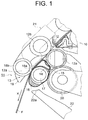
- FIG. 1 is a fragmentary side view showing a schematic configuration of a fiber bundle condensing device of a spinning machine according to the present embodiment.
- a fiber bundle condensing device 11 is disposed downstream of a drafting device 10.
- the drafting device 10 includes a delivery roller pair 12.
- the delivery roller pair 12 includes a lower front roller 12a and an upper front roller 12b.
- the upper front roller 12b is supported by a support member 19.
- the fiber bundle condensing device 11 includes a delivery portion 13, a suction pipe 14, an air-permeable apron 15, and an apron guide 16.
- the delivery portion 13 includes a lower nip roller 18a and an upper nip roller 18b.
- the lower nip roller 18a rotates integrally with a rotational shaft 17.
- a gear (not shown) is mounted to the rotational shaft 17.
- the gear is engaged with an intermediate gear 20.
- the intermediate gear 20 is engaged with a gear (not shown) that rotates integrally with the lower front roller 12a. With this configuration, the rotational force of the lower front roller 12a is transmitted to the lower nip roller 18a via the intermediate gear 20.
- the upper nip roller 18b is pressed against the lower nip roller 18a via the air-permeable apron 15.
- This pressing mechanism configures a nip portion 13a of the delivery portion 13.
- the air-permeable apron 15 and a fiber bundle F are placed on the nip portion 13a of the delivery portion 13.
- the upper nip roller 18b is supported by a pressing arm (not shown) via a support member 19 at every two spindle stations of the spinning machine.
- the suction pipe 14 is disposed downstream of the drafting device 10. More specifically, the suction pipe 14 is disposed downstream of the delivery roller pair 12 of the drafting device 10 and upstream of the nip portion 13a of the delivery portion 13 in a direction X in which the fiber bundle F is moved (hereinafter, the moving direction X).
- the suction pipe 14 is connected to a suction source (not shown) via a connection pipe 21.
- the air-permeable apron 15 is an endless belt having no ends, and formed of a woven fabric, such as the one having an appropriate air permeability.
- the air-permeable apron 15 is mounted in such a manner as to surround the suction pipe 14, the apron guide 16, and the lower nip roller 18a so that the air-permeable apron 15 passes through the nip portion 13a of the delivery portion 13.
- the air-permeable apron 15 transfers the fiber bundle F in the X direction while moving with the rotation of the lower nip roller 18a.
- a tip end 22a of the suction nozzle 22 is located below the apron guide 16.
- the suction nozzle 22 is adapted to suck the fiber bundle F discharged from the drafting device 10 when a fiber break has occurred.
- a distal end (not shown) of the suction nozzle 22 is connected to a single pneumatic duct (not shown) which is common to all of the spindle stations of the spinning machine.
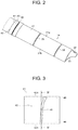
- FIG. 2 is a perspective view for illustrating the structure of the suction pipe 14 used in the fiber bundle condensing device 11 of FIG. 1 .
- the suction pipe 14 is a hollow and elongated pipe.
- the suction pipe 14 is disposed so as to extend in a direction crossing the moving direction X of the fiber bundle F.
- the suction pipe 14 extends longitudinally and perpendicularly to the plane of the sheet of FIG. 1 .
- the suction pipe 14 is made of aluminum and formed, for example, by extrusion molding.
- the suction pipe 14 includes three outer surfaces, namely, outer surfaces 31, 32, and 33.
- the outer surfaces will be referred to as the first outer surface 31, the second outer surface 32, and the third outer surface 33, respectively.
- the first outer surface 31 is positioned so as to extend along the moving path of the fiber bundle F and formed in a curved shape protruding outward.
- a plurality of suction holes 35 is formed in the first outer surface 31.
- the suction holes 35 are arranged at predetermined intervals in the longitudinal direction of the suction pipe 14. The intervals correspond to the positions of the spindle stations.
- Each suction hole 35 is formed in a slit shape extending in a direction crossing the longitudinal direction of the suction pipe 14.
- the second outer surface 32 is formed continuously from a first side 31a of the first outer surface 31, having a curved shape protruding inward.
- the third outer surface 33 is formed continuously from a second side 31b of the first outer surface 31, having a curved shape protruding inward.
- the second outer surface 32 and the third outer surface 33 are connected to each other at their sides located away from the first outer surface 31.
- a guide member 41 is attached to the suction pipe 14.
- the guide member 41 is a thin-walled member made of a metal.
- the guide member 41 is attached to the suction pipe 14 at a position corresponding to the mounting position of the air-permeable apron 15. It is to be noted that, in the present disclosure, a plurality of the guide members 41 are disposed at intervals along the longitudinal direction of the suction pipe 14. It is also to be noted, however, that only one of the guide members 41 is illustrated in FIG. 2 and description herein is made with reference to this representative guide member 14.
- the guide members 41 are attached to the suction pipe 14 corresponding to the respective suction holes 35.
- Each guide member 41 includes a guide surface 42 that is formed along the moving path of the fiber bundle F to guide the movement of the air-permeable apron 15.
- the air-permeable apron 15 moves with the rotation of the lower nip roller 18a while being in contact with the guide surface 42 of the guide member 41.
- the guide surface 42 is formed in a curved shape protruding outward, conforming to the first outer surface 31 of the suction pipe 14.
- a suction slit 43 is formed in the guide surface 42 of the guide member 41.
- the guide member 41 is attached to the suction pipe 14 so that the suction slit 43 is aligned with the suction hole 35 of the first outer surface 31 of the suction pipe 14. It is preferable that the suction hole 35 of the suction pipe 14 have the same shape and the same dimension as those of the suction slit 43. With the suction hole 35 thus formed before attaching the guide member 41 to the suction pipe 14, the guide member 41 may be attached to the suction pipe 14 easily and precisely by aligning the suction slit 43 with the suction hole 35. It is to be noted, however, that the shape and dimension of the suction hole 35 need not necessarily be the same as those of the suction slit 43.
- the suction hole 35 may be a hole which is greater than the suction slit 43 and has a different shape from that of the suction slit 43.
- FIG. 3 is a front view of the guide member 41
- FIG. 4 is a cross-sectional view of the guide member 41 taken along line IV-IV of FIG. 3 .
- the guide member 41 has a rectangular shape in a front view.
- the guide member 41 has two bent portions, namely, bent portions 45 and 46, formed at opposite ends thereof.
- the bent portion 45 is referred to as the first bent portion 45 and the bent portion 46 as the second bent portion 46.
- the first bent portion 45 is formed by bending a portion of the guide member 41 near one end of the suction slit 43 in the longitudinal direction thereof so as to bend from the first side 42a of the guide surface 42.
- the second bent portion 46 is formed by bending another portion of the guide member 41 near the other end of the suction slit 43 in the longitudinal direction thereof so as to bend from the second side 42b of the guide surface 42.
- the first bent portion 45 is bent conforming to the curved shape of the boundary between the first outer surface 31 and the second outer surface 32 of the suction pipe 14.
- the second bent portion 46 is bent conforming to the curved shape of the boundary between the first outer surface 31 and the third outer surface 33 of the suction pipe 14.
- FIG. 5 is a side view of the suction pipe 14 to which the guide member is attached
- FIG. 6 shows the suction pipe 14 as viewed in the direction of VI of FIG. 5 .
- the guide member 41 is attached to the suction pipe 14 such that the guide surface 42 of the guide member 41 overlaps with the first outer surface 31 of the suction pipe 14.
- the first bent portion 45 of the guide member 41 is disposed so as to overlap with the second outer surface 32 of the suction pipe 14.
- the second bent portion 46 is disposed so as to overlap with the third outer surface 33 of the suction pipe 14. In this way, the first bent portion 45 is hooked onto the second outer surface 32, and the second bent portion 46 is hooked onto the third outer surface 33.
- the guide member 41 is fixed to the suction pipe 14 with a fixation tape 51.
- the fixation tape 51 is an adhesive tape having an adhesive layer on one side of the substrate of the tape.
- Examples of the fixation tape 51 may include a resin tape including a resin substrate, a paper tape including a paper substrate, and a metallic tape including a metallic substrate.
- the fixation tape 51 should preferably be a resin tape.
- the fixation tape 51 should preferably be a metallic tape.
- the fixation tape 51 is attached to the second outer surface 32 and the third outer surface 33 of the suction pipe 14.
- the fixation tape 51 includes a first portion 51a and a second portion 51b.
- the first portion 51a overlaps with the first bent portion 45 of the guide member 41 on the second outer surface 32 of the suction pipe 14
- the second portion 51b overlaps with the second bent portion 46 of the guide member 41 on the third outer surface 33 of the suction pipe 14.
- the guide member 41 is fixed to the suction pipe 14 of the fiber bundle condensing device 11 with the fixation tape 51.
- the guide member 41 may be detached from the suction pipe 14 by removing the fixation tape 51 attached to the second outer surface 32 and the third outer surface 33 of the suction pipe 14, in order to replace the guide member 41.
- the guide surface 42 of the guide member 41 is disposed on the first outer surface 31 of the suction pipe 14 in an overlapping manner.
- the first bent portion 45 is hooked onto the second outer surface 32 of the suction pipe 14 and the second bent portion 46 is hooked onto the third outer surface 33 of the suction pipe 14.
- the position of the suction hole 35 of the suction pipe 14 and the position of the suction slit 43 of the guide member 41 are aligned.
- the fixation tape 51 is attached to the second outer surface 32 and the third outer surface 33 of the suction pipe 14.
- fixation tape 51 is attached such that the first portion 51a overlaps with the first bent portion 45 of the guide member 41 and the second portion 51b overlaps with the second bent portion 46 of the guide member 41. In this way the suction pipe 14 may be fixed to the guide member 41.
- the guide member 41 which has the guide surface 42 provided with the suction slit 43 is fixed to the suction pipe 14 with the fixation tape 51.
- the guide member 41 may be detached from the suction pipe 14 easily by removing the fixation tape 51 from the suction pipe 14, and the guide member 41 may be attached to the suction pipe 14 easily by attaching the fixation tape 51 to the suction pipe 14. Accordingly, the guide member 41 may be replaced easily. Furthermore, since no fasteners such as screws are used to fix the guide member 41, an increase in the number of parts and components resulting from the use of such fasteners and hence catching of cotton fly may be prevented. Furthermore, since there is no need of applying an adhesive agent to fix the guide member 41, the work of removing such an adhesive agent is eliminated.
- a single strip or sheet of the fixation tape 51 is used to fix a single guide member 41
- the fixation of the guide member 41 is not limited thereto.
- two guide members 41 that are adjacent to each other in the longitudinal direction of the suction pipe 14 may be fixed with a single strip or sheet of the fixation tape 51.
- three or more guide members 41 (not shown) that are adjacent in the longitudinal direction of the suction pipe 14 may be fixed with a single strip or sheet of the fixation tape 51.
- one strip or sheet of the fixation tape 51 may be used for the adjacent first bent portions 45, and another strip or sheet of the fixation tape 51 may be used for the adjacent second bent portions 46.
- a fiber bundle condensing device (11) of a spinning machine includes a suction pipe (14) that is disposed downstream of a drafting device (10), and an air-permeable apron (15) mounted on the suction pipe in such a manner as to surround the suction pipe (14).
- the fiber bundle condensing device (11) condenses a fiber bundle (F) drafted by the drafting device (10).
- the fiber bundle condensing device (11) includes a guide member (41) that is attached to the suction pipe (14) at a position corresponding to a mounting position of the air-permeable apron (15) and includes a guide surface (42) adapted to guide movement of the air-permeable apron (15), and a suction slit (43) formed in the guide surface (42); and a fixation tape (51) to fix the guide member (43) to the suction pipe (14).
Landscapes
- Engineering & Computer Science (AREA)
- Mechanical Engineering (AREA)
- Textile Engineering (AREA)
- Spinning Or Twisting Of Yarns (AREA)
Applications Claiming Priority (1)
| Application Number | Priority Date | Filing Date | Title |
|---|---|---|---|
| JP2018227228A JP7180333B2 (ja) | 2018-12-04 | 2018-12-04 | 紡機の繊維束集束装置 |
Publications (1)
| Publication Number | Publication Date |
|---|---|
| EP3663446A1 true EP3663446A1 (de) | 2020-06-10 |
Family
ID=68531396
Family Applications (1)
| Application Number | Title | Priority Date | Filing Date |
|---|---|---|---|
| EP19208231.1A Pending EP3663446A1 (de) | 2018-12-04 | 2019-11-11 | Vorrichtung zum verdichten eines faserbandes für eine spinnmaschine |
Country Status (3)
| Country | Link |
|---|---|
| EP (1) | EP3663446A1 (de) |
| JP (1) | JP7180333B2 (de) |
| CN (1) | CN111270360B (de) |
Cited By (1)
| Publication number | Priority date | Publication date | Assignee | Title |
|---|---|---|---|---|
| EP4047115A1 (de) * | 2021-02-17 | 2022-08-24 | Kabushiki Kaisha Toyota Jidoshokki | Faserbündelkondensationsvorrichtung einer spinnmaschine |
Families Citing this family (1)
| Publication number | Priority date | Publication date | Assignee | Title |
|---|---|---|---|---|
| BE1019331A5 (nl) | 2010-05-10 | 2012-06-05 | Flooring Ind Ltd Sarl | Vloerpaneel en werkwijzen voor het vervaardigen van vloerpanelen. |
Citations (7)
| Publication number | Priority date | Publication date | Assignee | Title |
|---|---|---|---|---|
| DE19903113A1 (de) * | 1999-01-27 | 2000-08-03 | Stahlecker Fritz | Vorrichtung zum Verdichten eines verstreckten Faserverbandes |
| DE10036786A1 (de) * | 2000-07-28 | 2002-02-07 | Stahlecker Fritz | Vorrichtung zum Verdichten eines Faserverbandes |
| CN1477248A (zh) * | 2003-07-07 | 2004-02-25 | 宁波德昌精密纺织机械有限公司 | 一种紧密纺纱器上的吸气管 |
| JP2008095233A (ja) | 2006-10-11 | 2008-04-24 | Toyota Industries Corp | 紡機における繊維束集束装置 |
| CN202214487U (zh) * | 2011-08-04 | 2012-05-09 | 江阴市华方新技术科研有限公司 | 可调换耐磨紧密纺异型吸风管 |
| CN202482530U (zh) | 2011-12-30 | 2012-10-10 | 日照裕鑫动力有限公司 | 组合式紧密纺集聚装置 |
| CN202786574U (zh) * | 2012-06-08 | 2013-03-13 | 常州市同和纺织机械制造有限公司 | 集聚纺纱异形管可更换集聚工作面机构 |
Family Cites Families (13)
| Publication number | Priority date | Publication date | Assignee | Title |
|---|---|---|---|---|
| GB542997A (de) * | 1940-07-01 | 1900-01-01 | ||
| JP3542069B2 (ja) * | 1999-01-06 | 2004-07-14 | 東邦テナックス株式会社 | ドラフト装置 |
| DE10158001A1 (de) * | 2001-11-22 | 2003-06-05 | Stahlecker Gmbh Wilhelm | Vorrichtung an einer Spinnmaschine zum Verdichten eines Faserverbandes |
| DE10218876A1 (de) * | 2002-04-26 | 2003-11-13 | Rieter Ag Maschf | Faserbandführungsvorrichtung |
| JP4419703B2 (ja) * | 2004-06-22 | 2010-02-24 | 株式会社豊田自動織機 | 紡機における繊維束集束装置 |
| DE102005045451B4 (de) * | 2005-09-22 | 2008-05-08 | Oerlikon Textile Gmbh & Co. Kg | Vorrichtung zum Verdichten eines Faserverbandes |
| JP2008111217A (ja) | 2006-10-30 | 2008-05-15 | Kanai Hiroaki | 毛羽伏せ具およびリング精紡機 |
| DE102007024234B4 (de) * | 2007-05-21 | 2022-06-23 | Wilhelm Stahlecker Gmbh | Streckwerk zum Verziehen eines Faserverbandes |
| JP5282724B2 (ja) | 2009-12-09 | 2013-09-04 | 株式会社豊田自動織機 | 紡機の繊維束集束装置における吸引パイプ及びその製造方法 |
| DE102010032341A1 (de) * | 2010-07-27 | 2012-02-02 | Wilhelm Stahlecker Gmbh | Streckwerk für einen Stapelfaserverband und Druckwalzenaggregat dafür |
| JP2015036456A (ja) * | 2013-08-12 | 2015-02-23 | 株式会社豊田自動織機 | 前紡機における繊維束送出装置の清掃装置 |
| CN204474827U (zh) * | 2014-12-12 | 2015-07-15 | 桐乡市张驰纺业有限公司 | 纺丝机构 |
| DE102015109644A1 (de) * | 2015-06-17 | 2016-12-22 | Rieter Ingolstadt Gmbh | Faserbandführung |
-
2018
- 2018-12-04 JP JP2018227228A patent/JP7180333B2/ja active Active
-
2019
- 2019-11-11 EP EP19208231.1A patent/EP3663446A1/de active Pending
- 2019-11-29 CN CN201911199966.1A patent/CN111270360B/zh active Active
Patent Citations (7)
| Publication number | Priority date | Publication date | Assignee | Title |
|---|---|---|---|---|
| DE19903113A1 (de) * | 1999-01-27 | 2000-08-03 | Stahlecker Fritz | Vorrichtung zum Verdichten eines verstreckten Faserverbandes |
| DE10036786A1 (de) * | 2000-07-28 | 2002-02-07 | Stahlecker Fritz | Vorrichtung zum Verdichten eines Faserverbandes |
| CN1477248A (zh) * | 2003-07-07 | 2004-02-25 | 宁波德昌精密纺织机械有限公司 | 一种紧密纺纱器上的吸气管 |
| JP2008095233A (ja) | 2006-10-11 | 2008-04-24 | Toyota Industries Corp | 紡機における繊維束集束装置 |
| CN202214487U (zh) * | 2011-08-04 | 2012-05-09 | 江阴市华方新技术科研有限公司 | 可调换耐磨紧密纺异型吸风管 |
| CN202482530U (zh) | 2011-12-30 | 2012-10-10 | 日照裕鑫动力有限公司 | 组合式紧密纺集聚装置 |
| CN202786574U (zh) * | 2012-06-08 | 2013-03-13 | 常州市同和纺织机械制造有限公司 | 集聚纺纱异形管可更换集聚工作面机构 |
Cited By (1)
| Publication number | Priority date | Publication date | Assignee | Title |
|---|---|---|---|---|
| EP4047115A1 (de) * | 2021-02-17 | 2022-08-24 | Kabushiki Kaisha Toyota Jidoshokki | Faserbündelkondensationsvorrichtung einer spinnmaschine |
Also Published As
| Publication number | Publication date |
|---|---|
| JP7180333B2 (ja) | 2022-11-30 |
| CN111270360A (zh) | 2020-06-12 |
| JP2020090734A (ja) | 2020-06-11 |
| CN111270360B (zh) | 2022-05-17 |
Similar Documents
| Publication | Publication Date | Title |
|---|---|---|
| EP3663446A1 (de) | Vorrichtung zum verdichten eines faserbandes für eine spinnmaschine | |
| JP4844336B2 (ja) | 紡機における繊維束集束装置 | |
| EP1614780B1 (de) | Reinigungsvorrichtung für Streckwalze | |
| CN101548038B (zh) | 纺纱机的牵伸装置 | |
| KR100462034B1 (ko) | 방적기에서의 섬유속 집속장치 | |
| CN1258622C (zh) | 在一台细纱机上用于压实一条纤维须条的装置 | |
| EP2333137A1 (de) | Vorrichtung zum Bündeln von Faserbündeln für eine Spinnmaschine | |
| KR20070004771A (ko) | 스프링 닥터 | |
| JP4179227B2 (ja) | 紡機における繊維束集束装置 | |
| CN105378163B (zh) | 用于纺纱机集聚纤维条的集聚装置 | |
| KR100507421B1 (ko) | 방사기의 섬유속 집속장치 및 그를 구비하는 링 방사 프레임 | |
| CN107109713B (zh) | 具有引导元件的保持架组件 | |
| EP2151514A1 (de) | Vorrichtung zum Sammeln von Faserbündeln für eine Spinnmaschine | |
| EP3754063A1 (de) | Kompaktspinnmaschine | |
| US4926627A (en) | Device to feed and open a fiber sliver on an open-end spinning device | |
| JP5698214B2 (ja) | 紡績糸製造においてドラフト領域及びガイド領域において設けられる弾性材料被覆ローラをシフト構造及びプリテンション装置を備えたエプロンで覆う装置及び方法 | |
| CN106544764B (zh) | 用于压实设备的清洁装置 | |
| CN114941190B (zh) | 纺织机的纤维束集束装置 | |
| JP2002235252A (ja) | 繊維ストランドを凝縮するための紡糸機のための集成装置 | |
| US8099835B2 (en) | Wearing coating for delivery rollers of a drawing roller frame | |
| JP2021175835A (ja) | 紡機における繊維束集束装置 | |
| CN111826756A (zh) | 纺机的纤维束集束装置 | |
| CN113373558B (zh) | 护环和具有护环的驱动装置 | |
| CN107541819B (zh) | 牵伸罗拉的清洁装置和牵伸装置 | |
| EP2889402A1 (de) | Innerer zylindrischer Körper einer Streckwalze, Walzenglied einer Streckwalze, Streckwalze, Streckvorrichtung und Druckluftspinnmaschine |
Legal Events
| Date | Code | Title | Description |
|---|---|---|---|
| PUAI | Public reference made under article 153(3) epc to a published international application that has entered the european phase |
Free format text: ORIGINAL CODE: 0009012 |
|
| STAA | Information on the status of an ep patent application or granted ep patent |
Free format text: STATUS: REQUEST FOR EXAMINATION WAS MADE |
|
| 17P | Request for examination filed |
Effective date: 20191111 |
|
| AK | Designated contracting states |
Kind code of ref document: A1 Designated state(s): AL AT BE BG CH CY CZ DE DK EE ES FI FR GB GR HR HU IE IS IT LI LT LU LV MC MK MT NL NO PL PT RO RS SE SI SK SM TR |
|
| AX | Request for extension of the european patent |
Extension state: BA ME |
|
| STAA | Information on the status of an ep patent application or granted ep patent |
Free format text: STATUS: EXAMINATION IS IN PROGRESS |
|
| 17Q | First examination report despatched |
Effective date: 20220519 |
|
| P01 | Opt-out of the competence of the unified patent court (upc) registered |
Effective date: 20230519 |
|
| GRAP | Despatch of communication of intention to grant a patent |
Free format text: ORIGINAL CODE: EPIDOSNIGR1 |
|
| STAA | Information on the status of an ep patent application or granted ep patent |
Free format text: STATUS: GRANT OF PATENT IS INTENDED |
|
| INTG | Intention to grant announced |
Effective date: 20240201 |
|
| GRAS | Grant fee paid |
Free format text: ORIGINAL CODE: EPIDOSNIGR3 |
|
| GRAA | (expected) grant |
Free format text: ORIGINAL CODE: 0009210 |
|
| STAA | Information on the status of an ep patent application or granted ep patent |
Free format text: STATUS: THE PATENT HAS BEEN GRANTED |