EP3603897B1 - Systeme und verfahren zur steuerung einer entfernten elektrischen werkzeugvorrichtung - Google Patents
Systeme und verfahren zur steuerung einer entfernten elektrischen werkzeugvorrichtung Download PDFInfo
- Publication number
- EP3603897B1 EP3603897B1 EP19189302.3A EP19189302A EP3603897B1 EP 3603897 B1 EP3603897 B1 EP 3603897B1 EP 19189302 A EP19189302 A EP 19189302A EP 3603897 B1 EP3603897 B1 EP 3603897B1
- Authority
- EP
- European Patent Office
- Prior art keywords
- power tool
- pack
- electronic processor
- remote control
- tool device
- Prior art date
- Legal status (The legal status is an assumption and is not a legal conclusion. Google has not performed a legal analysis and makes no representation as to the accuracy of the status listed.)
- Active
Links
- 238000000034 method Methods 0.000 title claims description 42
- 230000004044 response Effects 0.000 claims description 40
- 238000004891 communication Methods 0.000 claims description 30
- 230000009471 action Effects 0.000 claims description 13
- 239000000428 dust Substances 0.000 description 21
- 230000006870 function Effects 0.000 description 6
- 238000000605 extraction Methods 0.000 description 3
- 230000008569 process Effects 0.000 description 3
- 238000013500 data storage Methods 0.000 description 2
- 238000010586 diagram Methods 0.000 description 2
- 230000007246 mechanism Effects 0.000 description 2
- 238000012544 monitoring process Methods 0.000 description 2
- 230000005355 Hall effect Effects 0.000 description 1
- HBBGRARXTFLTSG-UHFFFAOYSA-N Lithium ion Chemical compound [Li+] HBBGRARXTFLTSG-UHFFFAOYSA-N 0.000 description 1
- 230000001413 cellular effect Effects 0.000 description 1
- 230000008859 change Effects 0.000 description 1
- 230000008878 coupling Effects 0.000 description 1
- 238000010168 coupling process Methods 0.000 description 1
- 238000005859 coupling reaction Methods 0.000 description 1
- 238000002788 crimping Methods 0.000 description 1
- 230000009849 deactivation Effects 0.000 description 1
- 229910001416 lithium ion Inorganic materials 0.000 description 1
- 238000010295 mobile communication Methods 0.000 description 1
Images


Classifications
-
- B—PERFORMING OPERATIONS; TRANSPORTING
- B25—HAND TOOLS; PORTABLE POWER-DRIVEN TOOLS; MANIPULATORS
- B25F—COMBINATION OR MULTI-PURPOSE TOOLS NOT OTHERWISE PROVIDED FOR; DETAILS OR COMPONENTS OF PORTABLE POWER-DRIVEN TOOLS NOT PARTICULARLY RELATED TO THE OPERATIONS PERFORMED AND NOT OTHERWISE PROVIDED FOR
- B25F5/00—Details or components of portable power-driven tools not particularly related to the operations performed and not otherwise provided for
-
- G—PHYSICS
- G08—SIGNALLING
- G08C—TRANSMISSION SYSTEMS FOR MEASURED VALUES, CONTROL OR SIMILAR SIGNALS
- G08C17/00—Arrangements for transmitting signals characterised by the use of a wireless electrical link
- G08C17/02—Arrangements for transmitting signals characterised by the use of a wireless electrical link using a radio link
-
- H—ELECTRICITY
- H01—ELECTRIC ELEMENTS
- H01M—PROCESSES OR MEANS, e.g. BATTERIES, FOR THE DIRECT CONVERSION OF CHEMICAL ENERGY INTO ELECTRICAL ENERGY
- H01M10/00—Secondary cells; Manufacture thereof
- H01M10/42—Methods or arrangements for servicing or maintenance of secondary cells or secondary half-cells
- H01M10/425—Structural combination with electronic components, e.g. electronic circuits integrated to the outside of the casing
-
- H—ELECTRICITY
- H02—GENERATION; CONVERSION OR DISTRIBUTION OF ELECTRIC POWER
- H02J—CIRCUIT ARRANGEMENTS OR SYSTEMS FOR SUPPLYING OR DISTRIBUTING ELECTRIC POWER; SYSTEMS FOR STORING ELECTRIC ENERGY
- H02J7/00—Circuit arrangements for charging or depolarising batteries or for supplying loads from batteries
- H02J7/00032—Circuit arrangements for charging or depolarising batteries or for supplying loads from batteries characterised by data exchange
-
- H—ELECTRICITY
- H01—ELECTRIC ELEMENTS
- H01M—PROCESSES OR MEANS, e.g. BATTERIES, FOR THE DIRECT CONVERSION OF CHEMICAL ENERGY INTO ELECTRICAL ENERGY
- H01M10/00—Secondary cells; Manufacture thereof
- H01M10/42—Methods or arrangements for servicing or maintenance of secondary cells or secondary half-cells
- H01M10/425—Structural combination with electronic components, e.g. electronic circuits integrated to the outside of the casing
- H01M2010/4271—Battery management systems including electronic circuits, e.g. control of current or voltage to keep battery in healthy state, cell balancing
-
- H—ELECTRICITY
- H01—ELECTRIC ELEMENTS
- H01M—PROCESSES OR MEANS, e.g. BATTERIES, FOR THE DIRECT CONVERSION OF CHEMICAL ENERGY INTO ELECTRICAL ENERGY
- H01M10/00—Secondary cells; Manufacture thereof
- H01M10/42—Methods or arrangements for servicing or maintenance of secondary cells or secondary half-cells
- H01M10/425—Structural combination with electronic components, e.g. electronic circuits integrated to the outside of the casing
- H01M2010/4278—Systems for data transfer from batteries, e.g. transfer of battery parameters to a controller, data transferred between battery controller and main controller
-
- H—ELECTRICITY
- H01—ELECTRIC ELEMENTS
- H01M—PROCESSES OR MEANS, e.g. BATTERIES, FOR THE DIRECT CONVERSION OF CHEMICAL ENERGY INTO ELECTRICAL ENERGY
- H01M2220/00—Batteries for particular applications
- H01M2220/30—Batteries in portable systems, e.g. mobile phone, laptop
-
- H—ELECTRICITY
- H02—GENERATION; CONVERSION OR DISTRIBUTION OF ELECTRIC POWER
- H02J—CIRCUIT ARRANGEMENTS OR SYSTEMS FOR SUPPLYING OR DISTRIBUTING ELECTRIC POWER; SYSTEMS FOR STORING ELECTRIC ENERGY
- H02J7/00—Circuit arrangements for charging or depolarising batteries or for supplying loads from batteries
- H02J7/0063—Circuit arrangements for charging or depolarising batteries or for supplying loads from batteries with circuits adapted for supplying loads from the battery
Definitions
- This application relates to controlling power tools with a mobile device through a battery pack of the power tool.
- Power tools in particular handheld power tools are increasingly relying on cordless rechargeable battery packs as a powering energy source.
- battery packs are preferably compact, lightweight, and can deliver relatively high current and voltage for powering the tool.
- EP-A-3528213 describes a method for controlling operation of a non-autonomous electric garden tool, comprising: monitoring, during operation of the tool, one or more operation parameters associated with the tool; and communicating, during operation of the tool, the one or more monitored operation parameters from a power source of the tool, which is operably connected with the tool, to an external electronic device, for displaying the one or more monitored operation parameters at the external electronic device.
- US-A-2015/162646 describes an apparatus that includes an apparatus body and a battery pack removable from the apparatus body.
- Each of the apparatus body and the battery pack includes a memory unit configured to store a use permission flag written after authentications for a pair of the apparatus body and the battery pack through near field communication with a portable terminal, and a control unit configured to permit energization when the use permission flag of the memory unit is ON.
- US-A-2017/057040 describes hand-held, battery-powered tools for performing operations such as crimping and cutting, and having a remote monitoring and control systems.
- a frame of the tool supports a working head, a battery, a motor connected to the battery, a controller and a camera. This document discloses the preamble of claim 1.
- WO-A-2017/075547 describes a system of light devices including a first light device and a second light device.
- the first light device having a first housing, a first light, a first transceiver, a first electronic processor.
- the second light having a second housing, a second light, a second transceiver, a second electronic processor.
- the first electronic processor is coupled to the first light and the first transceiver, and configured to control operation of the first light, and transmit, via the first transceiver a command to the second light device.
- the second electronic processor coupled to the second light and the second transceiver, and configured to receive, via the second transceiver, the command from the first light device, and change an operational parameter of the second light in response to the command from the first light device.
- the power tool device may further include a mode switch switchable between a first position for selecting a remote control mode and a second position for selecting a normal mode, wherein the tool electronic processor may place the power tool device in the remote control mode in response to a user placing the mode switch in the first position.
- the system may further comprise a second power tool device, wherein the pack electronic processor may be further configured to determine that the second power tool device is not remotely controllable when the battery pack is coupled to the second power tool device.
- the system may further comprising
- the mobile device may provide the remote control command in response to receiving the indication from the second pack electronic processor, wherein the action specified by the remote control command may be to turn on the power tool device.
- the second pack electronic processor may be further configured to
- the mobile device may provide a second remote control command to the pack electronic processor in response to receiving the second indication from the second pack electronic processor.
- the pack electronic processor may be further configured to
- the power tool device may include a mode switch switchable between a first position for selecting a remote control mode and a second position for selecting a normal mode, the method further comprising: detecting, using the tool electronic processor, that the mode switch is in the first position, wherein placing the power tool device in the remote control mode may be performed in response to detecting that the mode switch is in the first position.
- the method may further comprise determining, by the pack electronic processor, that a second power tool device is not remotely controllable when the battery pack is coupled to the second power tool device.
- a second power tool device may be coupled to a second battery pack, the method further comprising:
- the mobile device may provide the remote control command in response to receiving the indication from the second pack electronic processor, wherein the action specified by the remote control command may be to turn on the power tool device.
- the method may further comprise:
- the method may further comprise: providing, using the mobile device, a second remote control command to the pack electronic processor in response to receiving the second indication from the second pack electronic processor.
- the method may further comprise:
- the system includes a battery pack coupled to a power tool device.
- the battery pack includes a pack memory, a pack transceiver, and a pack electronic processor.
- the pack electronic processor is coupled to the pack memory and the pack transceiver and is configured to determine that the power tool device is remotely controllable.
- the pack electronic processor is further configured to receive, wirelessly via a pack transceiver of the battery pack, a remote control command from a mobile device, and to provide the remote control command to the power tool device.
- the system further includes a tool electronic processor of the power tool device in communication with the pack electronic processor.
- the tool electronic processor is configured to control the power tool device to perform an action specified by the remote control command in response to receiving the remote control command.
- the tool electronic processor is further configured to place the power tool device in a remote control mode in response to user input.
- Another embodiment provides a method for remote controlling a power tool device.
- the power tool device is powered by a battery pack.
- the method includes determining, by a pack electronic processor of the battery pack, that the power tool device is remotely controllable and receiving, wirelessly via a pack transceiver of the battery pack, a remote control command from a mobile device.
- the method also includes providing the remote control command, by the pack electronic processor to the tool electronic processor of the power tool device, and controlling, using the tool electronic processor, the power tool device to perform an action specified by the remote control command in response to the tool electronic processor receiving the remote control command.
- the method further includes placing the power tool device in a remote control mode in response to user input.
- the battery pack connectable to a power tool device and configured to facilitate remote control of the power tool device by a mobile device.
- the battery pack includes a plurality of cells providing operating power to the power tool device, wherein the power tool device is coupled to the battery pack and a pack transceiver.
- the battery pack also includes a pack electronic processor electrically coupled to the transceiver.
- the pack electronic processor is further configured to determine that the connected power tool device is remotely controllable and receive, wirelessly via the pack transceiver, a remote control command from the mobile device.
- the pack electronic processor is also configured to provide, via a communication link between the pack electronic processor and a tool electronic processor of the power tool device, the remote control command.
- the remote control command specifies an action to be performed by the power tool device.
- the power tool device performs the function specified by the remote control command in response to receiving the remote control command.
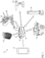
- FIG. 1 illustrates a communication system 100 including various power tool devices 110 powered by a battery pack 120.
- the system 100 also includes a mobile device 130 that can control the power tool devices 110 through the battery pack 120.
- the power tool devices 110 may include motorized power tool devices (for example, a miter saw 110A, a drill-driver 1 10B, a shop vacuum 110C, and the like) or non-motorized electrical devices (for example, a work radio 110D, a work light 110E, and the like).
- Each of the power tool devices 110A-E may be individually referred to as the power tool device 110, or collectively as the power tool devices 110.
- the power tool devices 110 may be described as electrically powered devices that are configured to be coupled to and powered by a power tool battery pack (e.g., the battery pack 120) that is configured to be coupled to and power a motorized power tool (e.g., a drill, a saw, and the like).
- a power tool battery pack e.g., the battery pack 120
- a motorized power tool e.g., a drill, a saw, and the like.
- the battery pack 120 is a power tool battery pack having a nominal voltage of, for example, 12 Volts, 18 Volts, and the like.
- the battery pack 120 includes a housing 140, a tool interface 150, and a latch 160 controlled by actuator 170 to selectively latch the tool interface 150 to a battery interface of the power tool 110.
- the mobile device 130 is a mobile communication device, for example, a smart telephone, a tablet computer, a laptop computer, a personal digital assistant, a smart wearable device (e.g., smart watch), and the like.
- the power tool device 110 includes a tool electronic processor 200, a tool memory 205, and tool electronics 210.
- the tool electronic processor 200 may be implemented as, for example, a microprocessor, a microcontroller, a field programmable gate array, an application specific integrated circuit, or the like.
- the tool memory 205 may be a part of the tool electronic processor 200 or may be a separate component.
- the tool memory 205 may include, for example, a program storage area and a data storage area.
- the tool memory 205 stores executable instructions that when executed by the tool electronic processor 200, cause the power tool device 110 to perform the functions described herein.
- the tool electronic processor 200 controls the functions of the power tool device 110 and enables communication between the power tool device 110 and the battery pack 120.
- the tool electronics 210 may include a switch bridge and a motor (not shown) when the power tool device 110 is a motorized power tool and may include other electronics (e.g., LEDs, radio transceiver, speaker, and the like) when the power tool device 110 is a non-motorized electronic device.
- the tool electronics 210 are controlled by the tool electronic processor 200.
- the tool electronic processor 200 is configured to one or more of enable the tool electronics 210, disable the tool electronics 210, and modify operating characteristics (e.g., motor power, LED brightness, radio tuning, speaker volume, and the like).
- the battery pack 120 includes battery cells 215, a pack electronic processor 220, a pack memory 225, and a pack transceiver 230 within the housing 140.
- the pack electronic processor 220, the pack memory 225, and the pack transceiver 230 communicate over one or more control and or data buses (for example, a communication bus 235).
- the battery cells 215 may be arranged in a series, parallel, or series-parallel combination.
- the battery cells 215 include one or more series strings of five cells connected in parallel.
- the battery cells 215 have a lithium-ion based chemistry and each provide approximately 3.6 nominal voltage. In other embodiments, the battery cells 215 have different chemistry, voltage output, or both.
- the battery cells 215 provide operating power to the other components of the battery pack 120. Additionally, operating power from the battery cells 215 is provided to the power tool device 110 over power terminals 240.
- the pack electronic processor 220 may be implemented as, for example, a microprocessor, a microcontroller, a field programmable gate array, an application specific integrated circuit, or the like.
- the pack memory 225 may be a part of the pack electronic processor 220 or may be a separate component.
- the pack memory 225 may include, for example, a program storage area and a data storage area.
- the pack memory 225 stores executable instructions that when executed by the pack electronic processor 220, cause the battery pack 120 to perform the functions described herein.
- the pack electronic processor 220 communicates with the tool electronic processor 200 over a communication terminal 245 to exchange data and control signals.
- the communication terminals 245 may implement a serial communication system for example, an RS-485 link or the like to facilitate communications between the pack electronic processor 220 and the tool electronic processor 200.
- the pack electronic processor 220 and the tool electronic processor 200 may communicate over near-field wireless communication link, for example, a Bluetooth ® connection or the like.
- the power tool device 110 and battery pack 120 include respective wireless transceivers to facilitate the wireless communications.
- the pack transceiver 230 facilitates communication between the battery pack 120 and an external device, for example, the mobile device 130 over a wireless communication network.
- the pack transceiver 230 includes a combined transmitter-receiver component.
- the pack transceiver 230 includes separate transmitter and receiver components.
- the power tool device 110 and the battery pack 120 may include more or fewer components and may perform functions other than those described herein.
- the mobile device 130 includes a device electronic processor 310, a device memory 320, a device transceiver 330, and device input/output interface 340.
- the device electronic processor 310, the device memory 320, the device transceiver 330, and the device input/output interface 340 communicate over one or more control and/or data buses (for example, a communication bus 350).
- the mobile device 130 may include more or fewer components and may perform functions other than those described herein.
- the device electronic processor 310 may be implemented as, for example, a microprocessor, a microcontroller, a field programmable gate array, an application specific integrated circuit, or the like.
- the device memory 320 may store executable instructions that are executed by the device electronic processor 310 to carry out the functionality of the mobile device 130 described herein.
- the device transceiver 330 facilitates communication between the mobile device 130 and an external device, for example, the battery pack 120 over a wireless communication network.
- the device transceiver 330 includes a combined transmitter-receiver component.
- the device transceiver 330 includes separate transmitter and receiver components.
- the device transceiver 330 is controlled by the device electronic processor 310, for example, to transmit and receive data between the mobile device 130 and the battery pack 120.
- the device input/output interface 340 may include one or more input mechanisms (e.g., a keypad, a mouse, and the like), one or more output mechanisms (e.g., a display, a speaker, and the like), or a combination of the two (e.g., a touch screen, or the like).
- input mechanisms e.g., a keypad, a mouse, and the like
- output mechanisms e.g., a display, a speaker, and the like
- a combination of the two e.g., a touch screen, or the like.
- the mobile device 130 also includes a mobile application 360, which is an application designed for a mobile operating system for use on the mobile device 130.
- the device memory 320 may store the mobile application 360 and the device electronic processor 310 executes the mobile application 360 to enable the mobile device 130 to carry out the functionality of the mobile application 360 described herein.
- the mobile application 360 may communicate with the battery pack 120 over a connection between the mobile device 130 and the battery pack 120.
- the mobile application 360 may include a graphical user interface in that, execution of the mobile application 360 by the device electronic processor 310 may generate a graphical user interface on a display (e.g., input/output interface 340) of the mobile device 130.
- the mobile device 130 may convey information to a user through display of the graphical user interface and may receive user input via the graphical user interface (i.e., the input/output interface 340).
- the mobile device 130 (via the device transceiver 330) and the battery pack 120 (via the pack transceiver 230) communicate over a direct wireless connection, for example, a Bluetooth ® connection, a ZigBee ® connection, or the like.
- the mobile device 130 (via the device transceiver 330) and the battery pack 120 (via the pack transceiver 230) communicate over an indirect wireless connection, for example, over a cellular network, over the Internet, or the like.
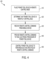
- FIG. 4 is a flowchart illustrating an exemplary method 400 for remotely controlling the power tool device 110.
- the method 400 includes placing the power tool device 110 in a remote control mode (at step 410).
- the power tool device 110 may include a mode switch (not shown) that can be actuated by a user to select a mode of the power tool device 110.
- the mode switch may be between a first position for selecting the remote control mode and a second position for selecting a normal mode (i.e., deselecting the remote control mode) by the user.
- the tool electronic processor 200 receives position information of the mode switch and places the power tool device 110 in the selected mode.
- the tool electronic processor 200 determines that the mode switch is in the first position and places the power tool device 110 in the remote control mode.
- the power tool device 110 can be remotely controlled by the mobile device 130 as described below.
- the power tool device 110 ignores (e.g., discards) commands received from the mobile device 130 without executing the received commands.
- the method 400 also includes determining, by the pack electronic processor 220, that the power tool device 110 is remotely controllable (at step 420).
- the remote control feature may not be provided on every power tool device 110 configured to be coupled to and powered by the battery pack 120.
- the remote control feature may be provided on the work radio 110D, the work light 110E, and the shop vacuum 110C, but may not be provided on the miter saw 110A or the drill-driver 11 0B.
- the pack electronic processor 220 determines whether the power tool device 110 is remotely controllable using identification signals received from the power tool device 110.
- the tool electronic processor 200 communicates identification signals over the communication terminal 245 to the pack electronic processor 220.
- the identification signals may include for example, a type of the power tool (e.g., by model number), which is then used by the pack electronic processor 220 to access and retrieve from a lookup table an indication of whether the power tool device 110 is remotely controllable.
- the lookup table may be on the stored on the pack memory 225, the device memory 320, or a combination thereof.
- the identification signals include an explicit indication of whether the power tool device 110 is remotely controllable or not remotely controllable.
- the battery pack 120 includes a sensor in communication with the pack electronic processor 220 that is configured to detect whether the power tool device 110 is remotely controllable.
- the sensor of the battery pack 120 may be a Hall effect sensor configured to detect a magnetic field, and the power tool device 110 that is remotely controllable may include a magnet near its battery pack interface.
- the sensor Upon coupling the power tool device 110 and the battery pack 120, the sensor provides an output to the pack electronic processor 220 indicative of the presence (or absence) of the magnet or indicative of the pole orientation of the magnet, and the output is indicative of whether the power tool device 110 is remotely controllable.
- power tool devices 110 having no such magnet, or having a magnet with a pole orientation representing that the device is not remotely controllable are determined by the pack electronic processor 220 to be not remotely controllable.
- Power tool devices 110 having a magnet, or having a magnet with a pole orientation representing that the device is remotely controllable are determined by the pack electronic processor 220 to be remotely controllable.
- the method 400 further includes receiving, by the pack electronic processor 220, a remote control command from the mobile device 130 (at step 430).
- the remote control command can be a command to, for example, turn the power tool device ON/OFF, activate a motor of the power tool device, switch an LED ON/OFF, adjust a radio station tuning, adjust an LED brightness, adjust a speaker volume, adjust a motor speed, and the like.
- the command can be selected on a graphical user interface of the mobile application 360.
- the battery pack 120 may communicate the type or identification information of the power tool device 110 connected to the battery pack 120 to the mobile device 130.
- the mobile device 130 may display a list of commands a user can select on the graphical user interface of the mobile application 360.
- the mobile device 130 When the mobile device 130 receives a selection of the remote control command from the list of commands (e.g., based on user input received by the device input/output interface 340), the mobile device 130 transmits the remote control command to the battery pack 120 via the device transceiver 330. Particularly, the pack electronic processor 220 receives the remote control command wirelessly via the pack transceiver 230.
- the method also includes providing, by the pack electronic processor 220, the remote control command to the tool electronic processor 200 of the power tool device 110 (at step 440).
- the pack electronic processor 220 relays the command received from the mobile device 130 to the tool electronic processor 200.
- the pack electronic processor 220 and the tool electronic processor 200 communicate over the communication terminal 245 or over a near-field communication link.
- the pack electronic processor 220 provides the remote control command to the tool electronic processor 200 via the communication terminal 245 or the near-field communication link.
- the pack electronic processor 220 may provide remote control command in response to determining that the power tool device 110 is remotely controllable, that the power tool device 110 is in a remote control mode, or both.
- the method 400 further includes controlling, by the tool electronic processor 200, the power tool device 110 to perform an action specified by the remote control command (at step 450).
- the tool electronic processor 200 in response to receiving the remote control command, controls the tool electronics 210 to perform the action specified by the remote control command.
- the tool electronic processor 200 turns the power tool device ON/OFF, activates a motor of the power tool device, switches an LED ON/OFF, adjusts a radio station tuning, adjusts an LED brightness, adjusts a speaker volume, adjusts a motor speed, and the like.
- the power tool device 110 operates in a lower power draw mode until a remote control command is received from the battery pack 120.
- the power draw is sufficient to maintain communication with the battery pack 120 and monitor for remote control commands, but not sufficient to perform the actions specified by the remote control command.
- the tool electronic processor 200 switches the power tool device 110 to the high power draw mode to perform the action specified by the remote control command.
- steps of the method 400 are illustrated in a particular serial order, in some embodiments, one or more of the steps are executed in parallel or in a different order than illustrated. For example, one or both of steps 410 and 420 may occur in parallel with or after step 430.
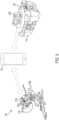
- FIG. 5 illustrates one example system 500 for implementing a remote controlling of power tool devices 110.
- the system 500 includes the miter saw 110A (for example, a first power tool device) connected to a first battery pack 120A, the shop vacuum 110C (for example, a second power tool device) connected to a second battery pack 120B, and the mobile device 130.
- the first battery pack 120A and the second battery pack 120B are examples of the battery pack 120 described above. Accordingly, the description provided above with respect to the battery pack 120 similarly applies to the first battery pack 120A and the second battery pack 120B.
- the mobile device 130 wirelessly communicates with the first battery pack 120A and the second battery pack 120B as described above.
- a hose 505 of the shop vacuum 110C is directly coupled to a dust port 510 of the miter saw 110A.
- the dust port 510 includes a dust intake end 515 near the saw blade to extract dust during a cut and a dust exhaust end, opposite the dust intake end 515, to expel extracted dust into the hose 505 coupled to the dust port. Still, users may need to manually turn on and off the shop vacuum 110 with each cut, or leave the shop vacuum 110 enabled between cuts despite a lack of dust needing extraction between cuts.
- FIG. 6 is a flowchart illustrating an exemplary method 600 for automating dust collection during operation of a miter saw 110A.
- the method 600 includes determining, by the device electronic processor 310, that the miter saw 110A (i.e., the first power tool device 110) is being operated (at step 610).
- the miter saw 110A i.e., the first power tool device 110
- a pack electronic processor of the first battery pack 120A detects a power draw when the user operates the miter saw 110A, for example, using a current sensor electrically connected to the power terminals of the first battery pack 120A.
- the pack electronic processor of the first battery pack 120A sends a signal, via the pack transceiver, indicating that the miter saw 110A is being operated to the mobile device 130 in response to detecting the power draw.
- the device electronic processor 310 of the mobile device 130 determines that the miter saw 110A is being operated upon receiving this signal from the first battery pack 120A.
- the method 600 also includes providing, by the device electronic processor 310, a remote control command to the second battery pack 120B in response to the determination that the miter saw 110A is being operated (at step 620). For example, in response to determining that the miter saw 110A is being operated, the device electronic processor 310 transmits the remote control command via the device transceiver 330, and the remote command is received by the second battery pack 120B.
- the remote control command is a request to turn the shop vacuum 110C (i.e., the second power tool 110) ON (i.e., to activate a motor of the shop vacuum 110C).
- the method further includes controlling the shop vacuum to turn ON in response to the remote control command received by the second battery pack 120B (at step 630).
- the pack electronic processor 220 of the second battery pack 120B relays the remote control command to the tool electronic processor 200 of the shop vacuum 110C.
- the tool electronic processor 200 of the shop vacuum 110C switches the shop vacuum 110 from the low power draw mode to the high power draw mode and activates the motor of the shop vacuum 110C.
- the shop vacuum 110C may be operated essentially simultaneously with the miter saw 110A without any user intervention. In other words, when the miter saw 110A is activated by the user, the shop vacuum 110C is activated. This allows the dust collection process to be automated, which saves time for the user and provided a more efficient dust extraction.
- a similar technique is used to deactivate the shop vacuum 110C in response to deactivation of the miter saw 110 by the user.
- the device electronic processor 310 determines that the miter saw 110A (i.e., the first power tool device 110) has ceased being operated.
- the pack electronic processor 220 of the first battery pack 120A detects a lack of power draw by the miter saw 110A in response to the user releasing a trigger of the saw.
- the pack electronic processor 220 of the first battery pack 120A sends a signal, via the pack transceiver, indicating that the miter saw 110A has ceased being operated to the mobile device.
- the device electronic processor 310 of the mobile device 130 determines that the miter saw 110A has ceased being operated.
- the device electronic processor 310 provides a second remote control command to the second battery pack 120B in response to the determination that the miter saw 110A has ceased being operated. For example, in response to determining that the miter saw 110A has ceased being operated, the device electronic processor 310 transmits the second remote control command via the device transceiver 330, and the second remote command is received by the second battery pack 120B.
- the second remote control command is a request to turn the shop vacuum 110C (i.e., the second power tool 110) OFF (i.e., to deactivate a motor of the shop vacuum 110C).
- the shop vacuum is controlled to turn OFF in response to the second remote control command received by the second battery pack 120B.
- the pack electronic processor 220 of the second battery pack 120B relays the second remote control command to the tool electronic processor 200 of the shop vacuum 110C.
- the tool electronic processor 200 of the shop vacuum 110C switches the shop vacuum 110 from the high power draw mode to the low power draw mode and deactivates the motor of the shop vacuum 110C. Accordingly, the shop vacuum 110C may be enabled and disabled essentially simultaneously with the miter saw 110A without any user intervention.
- the shop vacuum 110C when the miter saw 110A is activated by the user, the shop vacuum 110C is activated, and when the miter saw 110A is deactivated by the user, the shop vacuum 110C is deactivated. This allows the dust collection process to be automated, which saves time for the user and provided a more efficient dust extraction.
- the first battery pack 120A and the second battery pack 120B communicate directly bypassing the mobile device 130.
- the mobile device 130 may be used to communicatively connect the first battery pack 120A and the second battery pack 120B.
- the mobile device 130 may be used to pair (for example, Bluetooth ® pairing) the first battery pack 120A with the second battery pack 120B.
- a connection may be initiated using a graphical user interface (GUI) of a software application executing on the mobile device 130.
- GUI graphical user interface
- the mobile device 130 may detect that the battery packs 120A, 120B in wireless communication range; display an identifier for the battery packs 120A, 120B on the GUI; and allow a user to select on the GUI the first battery pack 120 and the second battery pack 120B for pairing with each another.
- GUI graphical user interface
- the mobile device 130 may provide identification information, connection identification information, and/or password information for the connection to each of the first battery pack 120A and the second battery pack 120B.
- the first battery pack 120A and the second battery pack 120B use the identification information, connection information, and/or password information to subsequently establish a communication link or to communicate with each other.
- the first battery pack 120A and the second battery pack 120B communicate directly to implement the method 600 as provided above.
- embodiments described herein provide, among other things, a system and method for remote control of a power tool device.
Landscapes
- Engineering & Computer Science (AREA)
- Power Engineering (AREA)
- Mechanical Engineering (AREA)
- Computer Networks & Wireless Communication (AREA)
- Physics & Mathematics (AREA)
- General Physics & Mathematics (AREA)
- Microelectronics & Electronic Packaging (AREA)
- Manufacturing & Machinery (AREA)
- Chemical & Material Sciences (AREA)
- Chemical Kinetics & Catalysis (AREA)
- Electrochemistry (AREA)
- General Chemical & Material Sciences (AREA)
- Charge And Discharge Circuits For Batteries Or The Like (AREA)
- Selective Calling Equipment (AREA)
Claims (13)
- System (100, 500) zum Fernsteuern einer angetriebenen Werkzeugvorrichtung (110, 110A), umfassend:eine angetriebene Werkzeugvorrichtung (110, 110A), die einen elektronischen Werkzeugprozessor (200) einschließt; undeinen Akkupack (120, 120A), der mit der angetriebenen Werkzeugvorrichtung (110, 110A) gekoppelt ist,dadurch gekennzeichnet, dassder Akkupack (120, 120A) einschließt: einen Packsendeempfänger (230),einen elektronischen Packprozessor (220), der mit dem Packsendeempfänger (230) gekoppelt ist und mit dem elektronischen Werkzeugprozessor (200) in Verbindung steht, wobei der elektronische Packprozessor (220) konfiguriert ist, um zu bestimmen, dass die angetriebene Werkzeugvorrichtung (110, 110A) fernsteuerbar ist, drahtlos über den Packsendeempfänger (230), einen Fernsteuerbefehl von einer mobilen Vorrichtung (130) zu empfangen, den Fernsteuerbefehl der angetriebenen Werkzeugvorrichtung (110, 110A) bereitzustellen,wobei der elektronische Werkzeugprozessor (200) konfiguriert ist, um die angetriebene Werkzeugvorrichtung (110, 110A) zu steuern, um eine Aktion, die durch den Fernsteuerbefehl spezifiziert wird, als Reaktion auf ein Empfangen des Fernsteuerbefehls von dem elektronischen Packprozessor (220) durchzuführen, und wobei der elektronische Werkzeugprozessor (200) ferner konfiguriert ist, um die angetriebene Werkzeugvorrichtung (110, 110A) in einen Fernsteuermodus als Reaktion auf das Empfangen einer Benutzereingabe zu setzen.
- System (100, 500) nach Anspruch 1, wobei die angetriebene Werkzeugvorrichtung ferner einen Modusschalter, der zwischen einer ersten Position zum Auswählen eines Fernsteuermodus und einer zweiten Position zum Auswählen eines Normalmodus umschaltbar ist, einschließt, wobei der elektronische Werkzeugprozessor die angetriebene Werkzeugvorrichtung in den Fernsteuermodus als Reaktion darauf setzt, dass ein Benutzer den Modusschalter in die erste Position setzt.
- System (100, 500) nach Anspruch 1 oder 2, ferner umfassendeine zweite angetriebene Werkzeugvorrichtung (110, 110C), wobei der elektronische Packprozessor (220) ferner konfiguriert ist, um zu bestimmen, dass die zweite angetriebene Werkzeugvorrichtung nicht fernsteuerbar ist, wenn der Akkupack mit der zweiten angetriebenen Werkzeugvorrichtung gekoppelt ist,oder ferner umfassendeine zweite angetriebene Werkzeugvorrichtung; undeinen zweiten Akkupack (120, 120B), der mit der zweiten angetriebenen Werkzeugvorrichtung gekoppelt ist, wobei der zweite Akkupack einschließt:einen zweiten Packsendeempfänger (230),einen zweiten elektronischen Packprozessor (220), der mit dem zweiten Packsendeempfänger gekoppelt ist, wobei der elektronische Packprozessor konfiguriert ist, um zu erfassen, dass die zweite angetriebene Werkzeugvorrichtung betrieben wird, und, über den zweiten Packsendeempfänger, eine Angabe, dass die zweite angetriebene Werkzeugvorrichtung betrieben wird, der mobilen Vorrichtung bereitzustellen.
- System (100, 500) nach Anspruch 3, wobei die mobile Vorrichtung (130) den Fernsteuerbefehl als Reaktion auf das Empfangen der Angabe von dem zweiten elektronischen Packprozessor (220) bereitstellt, wobei die Aktion, die durch den Fernsteuerbefehl spezifiziert wird, ist, die angetriebene Werkzeugvorrichtung (110, 110A) einzuschalten.
- System (100, 500) nach Anspruch 3 oder 4, wobei der zweite elektronische Packprozessor (220) ferner konfiguriert ist, um zu erfassen, dass die zweite angetriebene Werkzeugvorrichtung (110, 110C) aufgehört hat, betrieben zu werden, und,
über den zweiten Packsendeempfänger (230), eine zweite Angabe, dass die zweite angetriebene Werkzeugvorrichtung aufgehört hat, betrieben zu werden, der mobilen Vorrichtung (130) bereitzustellen. - System (110, 110C) nach Anspruch 5, wobei die mobile Vorrichtung (130) einen zweiten Fernsteuerbefehl dem elektronischen Packprozessor (220) als Reaktion auf das Empfangen der zweiten Angabe von dem zweiten elektronischen Packprozessor (220) bereitstellt undoptional, wobei der elektronische Packprozessor ferner konfiguriert ist, um, drahtlos über den Packsendeempfänger (230), den zweiten Fernsteuerbefehl von der mobilen Vorrichtung zu empfangen, den zweiten Fernsteuerbefehl der angetriebenen Werkzeugvorrichtung (110, 110A) bereitzustellen,wobei der elektronische Werkzeugprozessor (200) konfiguriert ist, um die angetriebene Werkzeugvorrichtung zu steuern, um sich als Reaktion auf das Empfangen des zweiten Fernsteuerbefehls von dem elektronischen Packprozessor auszuschalten.
- Verfahren zum Fernsteuern einer angetriebenen Werkzeugvorrichtung (110, 110A), die durch einen Akkupack (120, 120A) angetrieben wird, das Verfahren umfassend:Bestimmen, durch einen elektronischen Packprozessor (220) des Akkupacks, dass die angetriebene Werkzeugvorrichtung fernsteuerbar ist,Empfangen, drahtlos über einen Packsendeempfänger (230) des Akkupacks, eines Fernsteuerbefehls von einer mobilen Vorrichtung (130),Bereitstellen, unter Verwendung des elektronischen Packprozessors, des Fernsteuerbefehls an einen elektronischen Werkzeugprozessor (200) der angetriebenen Werkzeugvorrichtung,Steuern, unter Verwendung des elektronischen Werkzeugprozessors, der angetriebenen Werkzeugvorrichtung, um eine Aktion, die durch die Fernsteuervorrichtung spezifiziert wird, als Reaktion darauf durchzuführen, dass der elektronische Werkzeugprozessor den Fernsteuerbefehl empfängt, und Setzen, unter Verwendung des elektronischen Werkzeugprozessors (200), der angetriebenen Werkzeugvorrichtung (110, 110A) in einen Fernsteuermodus als Reaktion auf eine Benutzereingabe.
- Verfahren nach Anspruch 7, wobei die angetriebene Werkzeugvorrichtung einen Modusschalter, der zwischen einer ersten Position zum Auswählen eines Fernsteuermodus und einer zweiten Position zum Auswählen eines Normalmodus umschaltbar ist, einschließt, das Verfahren ferner umfassend:Erfassen, unter Verwendung des elektronischen Werkzeugprozessors, dass sich der Modusschalter in der ersten Position befindet, wobei das Setzen der angetriebenen Werkzeugvorrichtung in den Fernsteuermodus als Reaktion auf das Erfassen durchgeführt wird, dass sich der Modusschalter in der ersten Position befindet, undoptional ferner umfassend das Bestimmen, durch den elektronischen Packprozessor (220), dass eine zweite angetriebene Werkzeugvorrichtung (110, 110C) nicht fernsteuerbar ist, wenn der Akkupack mit der zweiten angetriebenen Werkzeugvorrichtung gekoppelt ist.
- Verfahren nach Anspruch 7 oder 8, wobei eine zweite angetriebene Werkzeugvorrichtung (110, 110C) mit einem zweiten Akkupack (120, 120B) gekoppelt ist, das Verfahren ferner umfassend:Erfassen, unter Verwendung eines zweiten elektronischen Packprozessors (220) des zweiten Akkupacks, dass die zweite angetriebene Werkzeugvorrichtung betrieben wird, undBereitstellen, über einen zweiten Packsendeempfänger (230) des zweiten Akkupacks, einer Angabe, dass die zweite angetriebene Werkzeugvorrichtung betrieben wird, an die mobile Vorrichtung (130).
- Verfahren nach Anspruch 9, wobei die mobile Vorrichtung (130) den Fernsteuerbefehl als Reaktion auf das Empfangen der Angabe von dem zweiten elektronischen Packprozessor (220) bereitstellt, wobei die Aktion, die durch den Fernsteuerbefehl spezifiziert wird, ist, die angetriebene Werkzeugvorrichtung (110, 110A) einzuschalten.
- Verfahren nach Anspruch 9 oder 10, ferner umfassend:Erfassen, unter Verwendung des zweiten elektronischen Packprozessors (220), dass die zweite angetriebene Werkzeugvorrichtung (110, 110C) aufgehört hat, betrieben zu werden, undBereitstellen, über den zweiten Packsendeempfänger (230), einer zweiten Angabe, dass die zweite angetriebene Werkzeugvorrichtung aufgehört hat, betrieben zu werden, an die mobile Vorrichtung (130).
- Verfahren nach Anspruch 11, ferner umfassend:
Bereitstellen, unter Verwendung der mobilen Vorrichtung (130), eines zweiten Fernsteuerbefehls an den elektronischen Packprozessor (220) als Reaktion auf das Empfangen der zweiten Angabe von dem zweiten elektronischen Packprozessor (220). - Verfahren nach Anspruch 12, ferner umfassend:Empfangen, drahtlos über den Packsendeempfänger (230), des zweiten Fernsteuerbefehls von der mobilen Vorrichtung (130),Bereitstellen, unter Verwendung des elektronischen Packprozessors (220), des zweiten Fernsteuerbefehls an den elektronischen Werkzeugprozessor (200) der angetriebenen Werkzeugvorrichtung (110, 110A) undSteuern, unter Verwendung des elektronischen Werkzeugprozessors, der angetriebenen Werkzeugvorrichtung, um die zweite angetriebene Werkzeugvorrichtung als Reaktion darauf auszuschalten, dass der elektronische Werkzeugprozessor den Fernsteuerbefehl empfängt.
Applications Claiming Priority (1)
| Application Number | Priority Date | Filing Date | Title |
|---|---|---|---|
| US201862712473P | 2018-07-31 | 2018-07-31 |
Publications (3)
| Publication Number | Publication Date |
|---|---|
| EP3603897A1 EP3603897A1 (de) | 2020-02-05 |
| EP3603897B1 true EP3603897B1 (de) | 2024-03-06 |
| EP3603897C0 EP3603897C0 (de) | 2024-03-06 |
Family
ID=67514366
Family Applications (1)
| Application Number | Title | Priority Date | Filing Date |
|---|---|---|---|
| EP19189302.3A Active EP3603897B1 (de) | 2018-07-31 | 2019-07-31 | Systeme und verfahren zur steuerung einer entfernten elektrischen werkzeugvorrichtung |
Country Status (6)
| Country | Link |
|---|---|
| US (4) | US11011053B2 (de) |
| EP (1) | EP3603897B1 (de) |
| CN (1) | CN210983054U (de) |
| AU (1) | AU2019100839A6 (de) |
| CA (1) | CA3050762A1 (de) |
| MX (1) | MX2019009092A (de) |
Families Citing this family (5)
| Publication number | Priority date | Publication date | Assignee | Title |
|---|---|---|---|---|
| US11011053B2 (en) | 2018-07-31 | 2021-05-18 | Tti (Macao Commercial Offshore) Limited | Systems and methods for remote power tool device control |
| GB2611434B (en) * | 2018-11-28 | 2023-10-04 | Lawrence Fowler Robert | A power tool system |
| US11571803B2 (en) * | 2019-05-30 | 2023-02-07 | Milwaukee Electric Tool Corporation | Power tool with combined chip for wireless communications and power tool control |
| AT523566A1 (de) * | 2020-03-10 | 2021-09-15 | Weber Hyraulik Gmbh | Verfahren zum Betreiben eines Rettungssystems mit einem mobilen Rettungsgerät |
| MX2021014829A (es) * | 2020-12-11 | 2022-07-12 | Techtronic Cordless Gp | Metodo para estimar el estado de carga de un paquete de baterias. |
Citations (1)
| Publication number | Priority date | Publication date | Assignee | Title |
|---|---|---|---|---|
| US20160311094A1 (en) * | 2013-10-21 | 2016-10-27 | Milwaukee Electric Tool Corporation | Adapter for power tool devices |
Family Cites Families (203)
| Publication number | Priority date | Publication date | Assignee | Title |
|---|---|---|---|---|
| US3626545A (en) | 1969-10-09 | 1971-12-14 | Perry W Sparrow | Central vacuum cleaner with remote control |
| JPS5828110B2 (ja) | 1978-10-19 | 1983-06-14 | 日立造船株式会社 | 片面段ボ−ル製造機における下部コルゲ−トロ−ル |
| GB2038615B (en) | 1978-12-31 | 1983-04-13 | Nintendo Co Ltd | Self-moving type vacuum cleaner |
| DE8808570U1 (de) | 1988-07-05 | 1988-09-08 | Bsg-Schalttechnik Gmbh & Co Kg, 7460 Balingen, De | |
| DE3822633A1 (de) | 1988-07-05 | 1990-01-18 | Bsg Schalttechnik | Vorrichtung mit einschaltautomatik fuer ein nebengeraet bei inbetriebnahme eines hauptgeraetes |
| DE3839932A1 (de) | 1988-11-26 | 1990-05-31 | Festo Kg | Stromversorgungseinheit |
| JP2553485Y2 (ja) | 1991-04-19 | 1997-11-05 | 株式会社マキタ | 集塵機の外部電源供給機構 |
| US5274878A (en) | 1991-07-23 | 1994-01-04 | Cen-Tec Systems Inc. | Remote control system for central vacuum systems |
| US7613590B2 (en) | 1992-11-17 | 2009-11-03 | Health Hero Network, Inc. | Modular microprocessor-based power tool system |
| US6424799B1 (en) | 1993-07-06 | 2002-07-23 | Black & Decker Inc. | Electrical power tool having a motor control circuit for providing control over the torque output of the power tool |
| JPH07222756A (ja) | 1994-02-14 | 1995-08-22 | Ricoh Elemex Corp | 医療用の照明付集塵装置 |
| US5606767A (en) | 1995-05-19 | 1997-03-04 | Crlenjak; Jack | Vacuum operated dust and debris removal and collection system |
| CA2175268C (en) | 1995-12-07 | 2001-11-20 | George E. Hendrix | Portable electric tool vacuum cleaner control |
| KR970032722A (ko) | 1995-12-19 | 1997-07-22 | 최진호 | 무선조정 청소기 |
| US5709007A (en) | 1996-06-10 | 1998-01-20 | Chiang; Wayne | Remote control vacuum cleaner |
| KR0175512B1 (ko) | 1996-09-30 | 1999-02-18 | 배순훈 | 진공청소기 |
| US5903462A (en) | 1996-10-17 | 1999-05-11 | The United States Of America As Represented By The Administrator Of The National Aeronautics And Space Administration | Computer implemented method, and apparatus for controlling a hand-held tool |
| US6967972B1 (en) | 1997-07-31 | 2005-11-22 | Cisco Technology, Inc. | Universal protocol conversion |
| US6058071A (en) * | 1998-08-10 | 2000-05-02 | The United States Of America As Represented By The Secretary Of The Navy | Magneto-inductive submarine communications system and buoy |
| US6339735B1 (en) | 1998-12-29 | 2002-01-15 | Friendly Robotics Ltd. | Method for operating a robot |
| US6675196B1 (en) | 1999-01-08 | 2004-01-06 | Amazon.Com, Inc. | Universal protocol for enabling a device to discover and utilize the services of another device |
| US6536536B1 (en) | 1999-04-29 | 2003-03-25 | Stephen F. Gass | Power tools |
| US6222285B1 (en) | 1999-09-07 | 2001-04-24 | Shop Vac Corporation | Intelligent switch control circuit |
| JP2001137158A (ja) | 1999-11-10 | 2001-05-22 | Matsushita Electric Ind Co Ltd | セントラルクリーナ |
| JP2001161607A (ja) | 1999-12-10 | 2001-06-19 | Matsushita Electric Ind Co Ltd | セントラルクリーナ |
| US7721006B2 (en) | 1999-12-30 | 2010-05-18 | Bally Gaming, Inc. | Meta-message set with real-time and database aspects |
| US7369635B2 (en) | 2000-01-21 | 2008-05-06 | Medtronic Minimed, Inc. | Rapid discrimination preambles and methods for using the same |
| DE60135166D1 (de) | 2000-03-16 | 2008-09-11 | Makita Corp | Werkzeugmaschinen |
| DE10029133A1 (de) | 2000-06-14 | 2002-01-03 | Hilti Ag | Elektrohandwerkzeuggerät mit Werkzeug |
| US7200671B1 (en) | 2000-08-23 | 2007-04-03 | Mks Instruments, Inc. | Method and apparatus for monitoring host to tool communications |
| AT411312B (de) | 2000-10-20 | 2003-11-25 | Universal Comm Platform Ag | Verfahren zum übermitteln von kurznachrichten (sms) zwischen rechnern im internet |
| JP2002209818A (ja) | 2001-01-19 | 2002-07-30 | Toshiba Tec Corp | 掃除装置 |
| JP4021625B2 (ja) | 2001-02-01 | 2007-12-12 | 株式会社マキタ | 集塵機及び電動工具 |
| DE10112129A1 (de) | 2001-03-14 | 2002-09-19 | Hilti Ag | Saugmodul |
| US6671583B2 (en) | 2001-03-30 | 2003-12-30 | Helix Technology Corporation | Vacuum system information network |
| KR100437372B1 (ko) | 2001-04-18 | 2004-06-25 | 삼성광주전자 주식회사 | 이동통신망을 이용한 로봇 청소 시스템 |
| KR100725516B1 (ko) | 2001-04-18 | 2007-06-08 | 삼성광주전자 주식회사 | 로봇 청소 시스템 |
| US20030033686A1 (en) | 2001-08-07 | 2003-02-20 | Te-Hsi Liu | Dust collecting apparatus for eraser |
| US7155618B2 (en) | 2002-03-08 | 2006-12-26 | Freescale Semiconductor, Inc. | Low power system and method for a data processing system |
| US8004664B2 (en) | 2002-04-18 | 2011-08-23 | Chang Type Industrial Company | Power tool control system |
| US7054696B2 (en) | 2002-07-18 | 2006-05-30 | Black & Decker Inc. | System and method for data retrieval in AC power tools via an AC line cord |
| US7296323B2 (en) | 2002-08-21 | 2007-11-20 | Hitachi Koki Co., Ltd. | Dust collector |
| US7146677B2 (en) | 2002-11-19 | 2006-12-12 | Ivan Litomisky | Energy saving vacuum system for particle, mist, and fume collection |
| JP4550357B2 (ja) | 2002-12-16 | 2010-09-22 | 株式会社マキタ | 集塵機の連動システム |
| DE10303006B4 (de) | 2003-01-27 | 2019-01-03 | Hilti Aktiengesellschaft | Handgeführtes Arbeitsgerät |
| JP4329369B2 (ja) | 2003-03-20 | 2009-09-09 | パナソニック電工株式会社 | 電動工具の使用支援方法及びその装置 |
| US6898542B2 (en) | 2003-04-01 | 2005-05-24 | Fisher-Rosemount Systems, Inc. | On-line device testing block integrated into a process control/safety system |
| KR200321249Y1 (ko) | 2003-04-19 | 2003-07-28 | 오토사이언스(주) | 무선리모콘 무선진공청소기 |
| DE10319022B4 (de) | 2003-04-28 | 2009-10-15 | Fette Gmbh | Anlage zur Herstellung von Tabletten |
| US7646155B2 (en) | 2003-04-30 | 2010-01-12 | Balck & Decker Inc. | Generic motor control system |
| US7102303B2 (en) | 2003-04-30 | 2006-09-05 | Black & Decker Inc. | Generic motor control system and method |
| US6851900B2 (en) | 2003-06-09 | 2005-02-08 | Python Perfect Cutter, Inc. | Hole cutting tool |
| US7330129B2 (en) | 2003-07-16 | 2008-02-12 | Black & Decker Inc. | System and method for data retrieval in AC power tools via an AC line cord |
| JP2005102791A (ja) | 2003-09-29 | 2005-04-21 | Hitachi Koki Co Ltd | 集塵機 |
| JP2005157551A (ja) | 2003-11-21 | 2005-06-16 | Canon Inc | 電子装置、及びその制御方法 |
| DE602004004233T2 (de) | 2003-11-24 | 2007-10-25 | Black & Decker Inc., Newark | Drahtloses Überwachungs- und Sicherheitssystem für Güter |
| US6913087B1 (en) | 2004-01-30 | 2005-07-05 | Black & Decker Inc. | System and method for communicating over power terminals in DC tools |
| US6845279B1 (en) | 2004-02-06 | 2005-01-18 | Integrated Technologies, Inc. | Error proofing system for portable tools |
| DE102004016171A1 (de) | 2004-03-30 | 2005-10-20 | Bosch Gmbh Robert | Handwerkzeugmaschine |
| JP2005296510A (ja) | 2004-04-15 | 2005-10-27 | Funai Electric Co Ltd | 監視カメラを備えた自走式掃除機 |
| US6856113B1 (en) | 2004-05-12 | 2005-02-15 | Cube Investments Limited | Central vacuum cleaning system motor control circuit mounting post, mounting configuration, and mounting methods |
| US20050279213A1 (en) | 2004-06-18 | 2005-12-22 | Otto John E | Method and apparatus for controlling the operation of a dust collector |
| US20090024757A1 (en) | 2004-07-30 | 2009-01-22 | Proctor David W | Automatic Protocol Determination For Portable Devices Supporting Multiple Protocols |
| US7298240B2 (en) * | 2004-09-24 | 2007-11-20 | David Lamar | Electronically enabling devices remotely |
| US7688028B2 (en) | 2004-10-18 | 2010-03-30 | Black & Decker Inc. | Cordless power system |
| KR100645379B1 (ko) | 2004-10-29 | 2006-11-15 | 삼성광주전자 주식회사 | 로봇 제어 시스템 및 로봇 제어방법 |
| US8005647B2 (en) | 2005-04-08 | 2011-08-23 | Rosemount, Inc. | Method and apparatus for monitoring and performing corrective measures in a process plant using monitoring data with corrective measures data |
| US7253577B2 (en) | 2005-05-20 | 2007-08-07 | Rockwell Automation Technologies, Inc. | Independent safety processor for disabling the operation of high power devices |
| US20060293788A1 (en) | 2005-06-26 | 2006-12-28 | Pavel Pogodin | Robotic floor care appliance with improved remote management |
| JP4515359B2 (ja) | 2005-08-31 | 2010-07-28 | 鹿島建設株式会社 | 集塵機の運転制御装置 |
| ATE455340T1 (de) * | 2005-11-18 | 2010-01-15 | Metabowerke Gmbh | Elektrohandwerkzeuggerät und akkupack hierfür |
| CA2535299C (en) | 2006-02-06 | 2014-07-22 | Dan Provost | Method for applying preset torques to threaded fasteners and a power tool therefor |
| JP4916266B2 (ja) | 2006-04-10 | 2012-04-11 | トヨタホーム株式会社 | 集塵装置を備える建物 |
| US20070283521A1 (en) | 2006-06-09 | 2007-12-13 | Electrolux Home Care Products Ltd. | Electronic control system for a vacuum system |
| JP2008000739A (ja) | 2006-06-21 | 2008-01-10 | Shinroku Nishiyama | 分岐集塵機能を備えた局所集塵システム |
| US20080022479A1 (en) | 2006-06-30 | 2008-01-31 | Kong Zhao | Power tool combination and synchronization control device |
| KR100833125B1 (ko) | 2006-07-11 | 2008-05-28 | 이재영 | 로봇 청소기의 집중 청소 제어방법 |
| US7825627B2 (en) | 2006-07-17 | 2010-11-02 | O2Micro International Limited | Monitoring battery cell voltage |
| JP4955332B2 (ja) | 2006-08-01 | 2012-06-20 | 株式会社マキタ | 集塵機の連動システム |
| DE102006038278B4 (de) | 2006-08-16 | 2022-02-17 | Andreas Stihl Ag & Co. Kg | Tragbares, handgeführtes Arbeitsgerät mit einer Datenverbindung zur Diagnose |
| US7822802B2 (en) | 2006-09-29 | 2010-10-26 | Fisher-Rosemount Systems, Inc. | Apparatus and method for merging wireless data into an established process control system |
| DE102006056834A1 (de) | 2006-12-01 | 2008-06-05 | Robert Bosch Gmbh | Elektrisches Zusatzgerät zu einem Elektrowerkzeug |
| SE530667C2 (sv) | 2007-01-15 | 2008-08-05 | Atlas Copco Tools Ab | Portabelt motordrivet verktyg med trådlös kommunikation med en stationär styrenhet |
| JP4876986B2 (ja) | 2007-03-12 | 2012-02-15 | パナソニック株式会社 | 電気掃除機 |
| US8750796B2 (en) | 2007-05-17 | 2014-06-10 | Abbott Medical Optics Inc. | Exclusive pairing technique for short-range communication devices |
| US8805530B2 (en) | 2007-06-01 | 2014-08-12 | Witricity Corporation | Power generation for implantable devices |
| EP2003552A3 (de) | 2007-06-15 | 2009-08-19 | Black & Decker, Inc. | Drahtmuffenladegerät |
| US20080311795A1 (en) | 2007-06-15 | 2008-12-18 | Brotto Daniele C | Adapter for cordless power tools |
| US7983789B2 (en) | 2007-09-14 | 2011-07-19 | Seagate Technology Llc | Collecting debris from a tool |
| JP2009083043A (ja) | 2007-09-28 | 2009-04-23 | Panasonic Electric Works Co Ltd | 電動工具の診断システム |
| CN201086970Y (zh) | 2007-09-30 | 2008-07-16 | 王希哲 | 多功能智能清洁器 |
| CN101234012A (zh) | 2007-12-14 | 2008-08-06 | 陈宏乔 | 一种具有无线移动监控功能的吸尘器 |
| US8443485B2 (en) | 2008-01-18 | 2013-05-21 | Black & Decker Inc. | Outlet box for power tool sense |
| US20090241283A1 (en) | 2008-01-21 | 2009-10-01 | Michael Loveless | Tool operated switch for vacuums |
| US8800103B2 (en) | 2008-02-28 | 2014-08-12 | Samsung Electronics Co., Ltd. | Upright type cleaner |
| KR20100006786A (ko) | 2008-07-10 | 2010-01-21 | 삼성전자주식회사 | 업라이트형 청소기 |
| EP2269286B1 (de) | 2008-02-29 | 2021-11-24 | Husqvarna AB | Elektrische säge |
| DE102008000980B4 (de) | 2008-04-03 | 2011-04-28 | Hilti Aktiengesellschaft | Verfahren zur Konfiguration einer Geräteelektronik eines handgeführten Arbeitsgeräts |
| DE102008000974A1 (de) | 2008-04-03 | 2009-10-08 | Hilti Aktiengesellschaft | Tragbarer Behälter eines handgeführten Arbeitsgeräts |
| DE102008000973A1 (de) | 2008-04-03 | 2009-10-08 | Hilti Aktiengesellschaft | Handgeführtes Arbeitsgerät |
| US7827334B2 (en) | 2008-06-26 | 2010-11-02 | Triune Ip Llc | Protocol method apparatus and system for the interconnection of electronic systems |
| DE102009000102A1 (de) | 2009-01-09 | 2010-07-15 | Hilti Aktiengesellschaft | Steuerungsverfahren für einen Akkumulator und eine Handwerkzeugmaschine |
| US9257865B2 (en) | 2009-01-22 | 2016-02-09 | Techtronic Power Tools Technology Limited | Wireless power distribution system and method |
| EP2382715A4 (de) | 2009-01-22 | 2012-08-29 | Techtronic Power Tools Tech | Drahtloses leistungsverteilungssystem und -verfahren für elektrowerkzeuge |
| US20100199453A1 (en) | 2009-02-09 | 2010-08-12 | Brotto Daniele C | Wireless particle collection system |
| US9198551B2 (en) | 2013-02-28 | 2015-12-01 | Omachron Intellectual Property Inc. | Surface cleaning apparatus |
| DE102009015642A1 (de) | 2009-03-21 | 2010-09-30 | Festool Gmbh | Sauggerät mit Funktionsmodul |
| EP2233993B1 (de) | 2009-03-25 | 2012-10-10 | IVAT GmbH | Steuerungs-Baukasten |
| DE102009029537A1 (de) | 2009-09-17 | 2011-03-31 | Robert Bosch Gmbh | Handwerkzeugmodul |
| JP5740563B2 (ja) | 2009-09-25 | 2015-06-24 | パナソニックIpマネジメント株式会社 | 電動工具 |
| JP2011079082A (ja) | 2009-10-06 | 2011-04-21 | Makita Corp | 集塵機の連動システム |
| DE102009046789A1 (de) | 2009-11-17 | 2011-05-19 | Robert Bosch Gmbh | Handwerkzeugmaschinenvorrichtung |
| DE102009047443B4 (de) | 2009-12-03 | 2024-04-11 | Robert Bosch Gmbh | Handwerkzeugmaschine |
| US8561623B2 (en) | 2009-12-08 | 2013-10-22 | Arnold Lowenstein | Apparatus for removing debris from gutters, troughs and other overhead open conduits |
| US8686685B2 (en) | 2009-12-25 | 2014-04-01 | Golba, Llc | Secure apparatus for wirelessly transferring power and communicating with one or more slave devices |
| JP5520095B2 (ja) | 2010-03-16 | 2014-06-11 | パナソニック株式会社 | 無線システム |
| CN102283615A (zh) | 2010-06-18 | 2011-12-21 | 苏州宝时得电动工具有限公司 | 吸尘器 |
| US9723229B2 (en) | 2010-08-27 | 2017-08-01 | Milwaukee Electric Tool Corporation | Thermal detection systems, methods, and devices |
| DE102010040336A1 (de) | 2010-09-07 | 2012-03-08 | Alfred Kärcher Gmbh & Co. Kg | Vorrichtung und Verfahren zum Erfassen einer Betriebszustandsänderung eines Elektrowerkzeuges sowie Staubsauger |
| FR2965082B1 (fr) | 2010-09-21 | 2012-09-28 | Inside Contactless | Procede et dispositif de modulation de charge active par couplage inductif |
| JP5618731B2 (ja) | 2010-09-27 | 2014-11-05 | 株式会社マキタ | 集塵機 |
| KR20120035047A (ko) | 2010-10-04 | 2012-04-13 | 삼성전자주식회사 | 무선 통신에서의 보안 연결 장치 및 방법 |
| US20120100803A1 (en) | 2010-10-20 | 2012-04-26 | Nokia Corporation | Delayed and conditional transport switch |
| JP5593200B2 (ja) | 2010-10-27 | 2014-09-17 | 株式会社マキタ | 電動工具システム |
| US9878432B2 (en) | 2010-11-04 | 2018-01-30 | Ingersoll-Rand Company | Cordless power tools with a universal controller and tool and battery identification |
| JP5828110B2 (ja) | 2011-06-22 | 2015-12-02 | パナソニックIpマネジメント株式会社 | 電動工具 |
| DE102011105306A1 (de) | 2011-06-22 | 2012-12-27 | Robert Bosch Gmbh | Tragbares Werkzeug mit drahtloser Messwertübertragung |
| US8874038B2 (en) | 2011-06-29 | 2014-10-28 | Broadcom Corporation | Secure communications via NFC device |
| JP6106155B2 (ja) | 2011-07-24 | 2017-03-29 | 株式会社マキタ | 携帯型バッテリパック充電システム、バッテリパックを充電する方法、及びそのためのアダプタ |
| US10124455B2 (en) | 2011-07-24 | 2018-11-13 | Makita Corporation | Theft-deterrence system for power tool system, and adapter and method therefor |
| US9621231B2 (en) | 2011-09-14 | 2017-04-11 | Nokia Technologies Oy | System, an apparatus, a device, a computer program and a method for device with short range communication capabilities |
| US20130068255A1 (en) | 2011-09-19 | 2013-03-21 | Heger Research Llc | Automated dust collection system |
| WO2013063507A1 (en) * | 2011-10-26 | 2013-05-02 | Milwaukee Electric Tool Corporation | Wireless tracking of power tools and related devices |
| DE102011087361B3 (de) | 2011-11-29 | 2013-01-31 | Hilti Aktiengesellschaft | Absaugvorrichtung und Steuerungsverfahren |
| US9189663B2 (en) * | 2011-12-02 | 2015-11-17 | The Stanley Works Israel, Ltd | Battery operated device and tag for a battery operated tool |
| CN102490172B (zh) | 2011-12-05 | 2014-09-24 | 东北林业大学 | 室内智能清洁机器人 |
| KR20140107434A (ko) | 2011-12-12 | 2014-09-04 | 지멘스 악티엔게젤샤프트 | 푸쉬-버튼 구성 세션들을 구동하기 위한 방법 및 디바이스들 |
| DE102012003076A1 (de) | 2012-02-17 | 2013-08-22 | Festool Group Gmbh & Co. Kg | Sauggerät mit einem Sauggerät-Sender und Extern-Kommunikationseinrichtung dafür |
| EP2628428B1 (de) | 2012-02-17 | 2019-05-22 | Festool GmbH | Sauggerät mit einer Ladeeinrichtung |
| DE102012003073A1 (de) | 2012-02-17 | 2013-08-22 | Festool Group Gmbh & Co. Kg | Sauggerät mit einer Sauggerät-Kommunikationseinrichtung |
| DE102012003077A1 (de) | 2012-02-17 | 2013-08-22 | Festool Group Gmbh & Co. Kg | Identifikationsverfahren für ein Sauggerät und eine Hand-Werkzeugmaschine |
| US20130241699A1 (en) | 2012-03-19 | 2013-09-19 | Redwood Systems, Inc. | Device tracking with lighting system |
| US9837203B2 (en) | 2012-03-29 | 2017-12-05 | Integrated Device Technology, Inc. | Apparatuses having different modes of operation for inductive wireless power transfer and related method |
| JP6022201B2 (ja) | 2012-05-07 | 2016-11-09 | シャープ株式会社 | 遠隔制御システム、上記遠隔制御システムの設定方法、通信端末装置、およびサーバ装置 |
| DE102012221997A1 (de) * | 2012-05-25 | 2013-11-28 | Robert Bosch Gmbh | Elektrowerkzeug |
| US9740182B2 (en) | 2012-06-08 | 2017-08-22 | Applied Materials, Inc. | Integrated controller solution for monitoring and controlling manufacturing equipment |
| JP5915398B2 (ja) | 2012-06-13 | 2016-05-11 | 株式会社リコー | 電動工具 |
| WO2014015072A2 (en) | 2012-07-17 | 2014-01-23 | Milwaukee Electric Tools Corporation | Universal protocol for power tools |
| EP2687331B1 (de) | 2012-07-19 | 2015-03-04 | Guido Valentini | Staubsauger, der an ein tragbares oder handgesteuertes Werkzeug mit einer Schwingungsüberwachungsvorrichtung angeschlossen ist. |
| JP2014057635A (ja) | 2012-09-14 | 2014-04-03 | Toshiba Corp | 電気掃除機 |
| CN203042139U (zh) | 2012-10-30 | 2013-07-10 | 许佑正 | 吸尘器的吸力控制装置 |
| US9226372B2 (en) * | 2013-01-09 | 2015-12-29 | Raptor Inventions, Llc | Hands-free lighting system |
| US20140213179A1 (en) | 2013-01-29 | 2014-07-31 | Einar Rosenberg | System and Method for Establishing Communications between Two Devices |
| US9466198B2 (en) * | 2013-02-22 | 2016-10-11 | Milwaukee Electric Tool Corporation | Wireless tracking of power tools and related devices |
| US9108285B2 (en) | 2013-03-15 | 2015-08-18 | Black & Decker Inc. | Cord clamp current sensor for dust collector |
| JP6038715B2 (ja) | 2013-04-10 | 2016-12-07 | 株式会社マキタ | 集塵機の連動システム |
| DE102013212003A1 (de) | 2013-06-25 | 2015-01-08 | Robert Bosch Gmbh | Handwerkzeugmaschine |
| US10398452B2 (en) | 2013-06-26 | 2019-09-03 | Buffalo Filter, Llc | Method and system for vacuum suction |
| KR102099940B1 (ko) | 2013-07-17 | 2020-04-13 | 삼성전자주식회사 | 무선 전력 전송 시스템에서의 동기 제어 방법 및 장치 |
| EP3028810B2 (de) | 2013-08-02 | 2023-12-27 | Makita Corporation | Staubabscheider |
| DE102013018278A1 (de) | 2013-10-31 | 2015-04-30 | Metabowerke Gmbh | Mehrzweckstaubsauger |
| DE102013222313A1 (de) | 2013-11-04 | 2015-05-07 | Robert Bosch Gmbh | Gerätesystem |
| DE102014209032A1 (de) | 2014-01-27 | 2015-07-30 | Robert Bosch Gmbh | Werkzeugmaschinenvorrichtung |
| EP2937031A1 (de) | 2014-04-23 | 2015-10-28 | HILTI Aktiengesellschaft | Modiwechsel |
| CN113472027A (zh) | 2014-05-18 | 2021-10-01 | 百得有限公司 | 电动工具系统 |
| DE102014007402A1 (de) | 2014-05-20 | 2015-11-26 | Festool Gmbh | Hand-Werkzeugmaschine mit einem Partikelabfuhr-Anschluss |
| US20170257472A1 (en) | 2014-06-04 | 2017-09-07 | Sonova Ag | Audio device network and audio device pairing method |
| WO2016001209A1 (en) * | 2014-07-03 | 2016-01-07 | Atlas Copco Industrial Technique Ab | Method, nodes and computer program of a tool communications network |
| US9768475B2 (en) * | 2014-08-12 | 2017-09-19 | Apollo America Inc. | Battery pack containing communication electronics |
| US9958893B2 (en) | 2014-09-19 | 2018-05-01 | Sears Brands, L.L.C. | Method and system for enabling wireless control in tools by use of portable power supply systems with embedded communication components |
| EP3009058B1 (de) | 2014-10-13 | 2021-02-24 | Guido Valentini | Pneumatisch an ein Elektrowerkzeug angeschlossener Staubsauger, Verfahren zur Steuerung der Betriebsparameter solch eines Staubsaugers und Elektrowerkzeug zum pneumatischen Anschließen an solch einen Staubsauger |
| JP6408371B2 (ja) | 2014-12-17 | 2018-10-17 | 株式会社マキタ | 電動工具及び集塵機 |
| US20160317131A1 (en) * | 2015-04-29 | 2016-11-03 | Siemens Medical Solutions Usa, Inc. | Medical diagnostic imaging ultrasound probe battery pack radio |
| AU2016257438B2 (en) * | 2015-05-04 | 2019-03-07 | Milwaukee Electric Tool Corporation | Power tool and method for wireless communication |
| US10380883B2 (en) * | 2015-06-16 | 2019-08-13 | Milwaukee Electric Tool Corporation | Power tool profile sharing and permissions |
| EP3341160B1 (de) | 2015-08-27 | 2023-10-04 | Hubbell Incorporated | Fernaktiviertes tragbares handwerkzeug |
| DE102015217180A1 (de) | 2015-09-09 | 2017-03-09 | Robert Bosch Gmbh | Tragbare Energiespeichervorrichtung zur Versorgung von Werkzeugen |
| US10345797B2 (en) * | 2015-09-18 | 2019-07-09 | Milwaukee Electric Tool Corporation | Power tool operation recording and playback |
| EP3805632B1 (de) | 2015-10-30 | 2023-05-17 | Milwaukee Electric Tool Corporation | Remote-lichtsteuerung, - konfiguration und - überwachung |
| EP3202537B1 (de) * | 2015-12-17 | 2019-06-05 | Milwaukee Electric Tool Corporation | System und verfahren zum konfigurieren eines strombetriebenen werkzeugs mit einem schlagmechanismus |
| CN108293037B (zh) | 2015-12-25 | 2020-11-17 | 三菱电机株式会社 | 供电装置、受电装置、供电系统、供电方法和电源管理方法 |
| JP6697885B2 (ja) | 2016-01-06 | 2020-05-27 | 株式会社マキタ | 電動作業機システム |
| EP3189942A1 (de) * | 2016-01-09 | 2017-07-12 | Chervon (HK) Limited | Elektrowerkzeugsystem |
| US10735467B2 (en) | 2016-01-11 | 2020-08-04 | Lg Electronics Inc. | Method and apparatus for controlling a device using bluetooth technology |
| CN108778651B (zh) * | 2016-02-03 | 2021-06-18 | 米沃奇电动工具公司 | 用于配置往复锯的系统和方法 |
| WO2017151045A1 (en) * | 2016-03-01 | 2017-09-08 | Husqvarna Ab | Wearable apparatus and system for use with outdoor power equipment |
| US11089925B2 (en) | 2016-03-31 | 2021-08-17 | Husqvarna Ab | Industrial automated vacuum cleaner and method for automated servicing of construction tools |
| US20170326696A1 (en) * | 2016-05-11 | 2017-11-16 | Daryll Halverson | Remote control power tool and method |
| DE102016111876A1 (de) | 2016-06-29 | 2018-01-04 | Metabowerke Gmbh | Tragbare Vorrichtung |
| DE102016113579A1 (de) | 2016-07-22 | 2018-01-25 | Metabo-Werke GmbH | Adapteranordnungssystem |
| CN106385661B (zh) | 2016-08-31 | 2019-09-20 | 泰凌微电子(上海)有限公司 | 配对请求、配对响应方法及配对请求、配对响应终端 |
| JP6808450B2 (ja) | 2016-11-04 | 2021-01-06 | 株式会社マキタ | 通信アダプタ装着装置及び電動作業機 |
| DE102017203685A1 (de) | 2017-03-07 | 2018-09-13 | Robert Bosch Gmbh | Verfahren zum Betrieb eines Systems |
| DE102017205072A1 (de) | 2017-03-27 | 2018-09-27 | Robert Bosch Gmbh | Sauggerät mit Steckmodul |
| CN106909156B (zh) | 2017-03-30 | 2020-03-17 | 北京小米移动软件有限公司 | 空气净化方法及装置 |
| DE112018001686T5 (de) | 2017-03-31 | 2019-12-19 | Makita Corporation | Elektrisch angetriebenes Werkzeug |
| CN111093452A (zh) | 2017-07-05 | 2020-05-01 | 米沃奇电动工具公司 | 用于电动工具之间的通信的适配器 |
| DE202017104107U1 (de) | 2017-07-10 | 2017-07-30 | Metabowerke Gmbh | Verwendung eines Saugschlauchs zur Benutzersteuerung |
| EP3664970A4 (de) * | 2017-08-07 | 2021-08-04 | Milwaukee Electric Tool Corporation | Elektrowerkzeug mit irreversibel verriegelbarem fach |
| CN109421032B (zh) | 2017-08-28 | 2023-12-22 | 创科电动工具科技有限公司 | 电动工具系统及其操作方法 |
| EP3528213A1 (de) | 2018-02-14 | 2019-08-21 | TTI (Macao Commercial Offshore) Limited | Verfahren zur steuerung des betriebs eines nichtautonomen elektrischen gartenwerkzeugs |
| US11011053B2 (en) * | 2018-07-31 | 2021-05-18 | Tti (Macao Commercial Offshore) Limited | Systems and methods for remote power tool device control |
| KR20200040533A (ko) * | 2018-10-10 | 2020-04-20 | 삼성전자주식회사 | 배터리를 관리하는 버스바, 그 제조 방법 및 이를 이용한 배터리 관리 장치 |
-
2019
- 2019-07-29 US US16/524,970 patent/US11011053B2/en active Active
- 2019-07-29 CA CA3050762A patent/CA3050762A1/en active Pending
- 2019-07-30 CN CN201921217941.5U patent/CN210983054U/zh active Active
- 2019-07-30 AU AU2019100839A patent/AU2019100839A6/en active Active
- 2019-07-31 EP EP19189302.3A patent/EP3603897B1/de active Active
- 2019-07-31 MX MX2019009092A patent/MX2019009092A/es unknown
-
2021
- 2021-04-21 US US17/236,442 patent/US11386774B2/en active Active
-
2022
- 2022-07-12 US US17/812,107 patent/US11890738B2/en active Active
-
2023
- 2023-12-21 US US18/392,617 patent/US20240123592A1/en active Pending
Patent Citations (1)
| Publication number | Priority date | Publication date | Assignee | Title |
|---|---|---|---|---|
| US20160311094A1 (en) * | 2013-10-21 | 2016-10-27 | Milwaukee Electric Tool Corporation | Adapter for power tool devices |
Also Published As
| Publication number | Publication date |
|---|---|
| CN210983054U (zh) | 2020-07-10 |
| US20210241609A1 (en) | 2021-08-05 |
| US20200043321A1 (en) | 2020-02-06 |
| CA3050762A1 (en) | 2020-01-31 |
| US11011053B2 (en) | 2021-05-18 |
| US11890738B2 (en) | 2024-02-06 |
| AU2019100839A6 (en) | 2019-09-26 |
| MX2019009092A (es) | 2020-02-03 |
| US20220351610A1 (en) | 2022-11-03 |
| EP3603897C0 (de) | 2024-03-06 |
| US20240123592A1 (en) | 2024-04-18 |
| US11386774B2 (en) | 2022-07-12 |
| AU2019100839A4 (en) | 2019-09-12 |
| EP3603897A1 (de) | 2020-02-05 |
Similar Documents
| Publication | Publication Date | Title |
|---|---|---|
| EP3603897B1 (de) | Systeme und verfahren zur steuerung einer entfernten elektrischen werkzeugvorrichtung | |
| US11738426B2 (en) | Power tool communication system | |
| JP5879347B2 (ja) | 自動車用ユニバーサルワイヤレス充電システム | |
| CN109491282A (zh) | 调试负载控制系统 | |
| RU2010112999A (ru) | Многофункциональные портативные электрические инструменты | |
| CN104993855A (zh) | 通信终端中的天线切换方法和通信终端 | |
| CN110783977B (zh) | 一种电动工具的电池包充放电方法、系统及电池包 | |
| CN106031090A (zh) | 用于在焊接系统上与无线通信终端进行数据交换和控制的系统和方法 | |
| CN105684743A (zh) | 园艺工具操作装置 | |
| KR20170070615A (ko) | 무선전력전송을 위한 무선전력전송시스템 및 이를 이용한 무선전력전송방법 | |
| CN105281412A (zh) | 感应式能量传输装置和用于借助于感应式能量传输装置进行位置识别和/或存在识别的方法 | |
| CN109891701A (zh) | 电气设备、电源装置、电气设备系统及管理装置 | |
| TW201817553A (zh) | 電動工具及其操控方法 | |
| EP4325144A3 (de) | System mit rückgewinnungspumpe und vakuumpumpe | |
| EP3517252A1 (de) | Bewegungsüberwachungsvorrichtung für handwerkzeug | |
| US11960265B2 (en) | Method for adapting an apparatus to a motor-driven tool, method for operating an apparatus in a type-dependent manner, apparatus for adaptation to a motor-driven tool, and system | |
| CN107081716A (zh) | 输送在工具处的从动工具的输送装置、工具以及工具和输送装置间的通信的方法 | |
| CN109297162B (zh) | 温控器控制方法和系统、移动终端和被控温控器 | |
| CN112512751A (zh) | 电动作业机 | |
| US11998164B2 (en) | System formed of suction device and hand-held power tool, and method for operating the system | |
| US20230296234A1 (en) | Externally controlled indicator | |
| US20210353121A1 (en) | System Formed of Suction Device and Hand-Held Power Tool, and Method for Operating the System | |
| US10560895B2 (en) | Method for operating a mobile device and a data management system, mobile device, data management system | |
| CN112907862A (zh) | 多功能微波雷达报警器 | |
| WO2018091263A1 (en) | Battery charging system and method |
Legal Events
| Date | Code | Title | Description |
|---|---|---|---|
| PUAI | Public reference made under article 153(3) epc to a published international application that has entered the european phase |
Free format text: ORIGINAL CODE: 0009012 |
|
| STAA | Information on the status of an ep patent application or granted ep patent |
Free format text: STATUS: THE APPLICATION HAS BEEN PUBLISHED |
|
| AK | Designated contracting states |
Kind code of ref document: A1 Designated state(s): AL AT BE BG CH CY CZ DE DK EE ES FI FR GB GR HR HU IE IS IT LI LT LU LV MC MK MT NL NO PL PT RO RS SE SI SK SM TR |
|
| AX | Request for extension of the european patent |
Extension state: BA ME |
|
| STAA | Information on the status of an ep patent application or granted ep patent |
Free format text: STATUS: REQUEST FOR EXAMINATION WAS MADE |
|
| 17P | Request for examination filed |
Effective date: 20200305 |
|
| RBV | Designated contracting states (corrected) |
Designated state(s): AL AT BE BG CH CY CZ DE DK EE ES FI FR GB GR HR HU IE IS IT LI LT LU LV MC MK MT NL NO PL PT RO RS SE SI SK SM TR |
|
| RAP1 | Party data changed (applicant data changed or rights of an application transferred) |
Owner name: TTI (MACAO COMMERCIAL OFFSHORE) LIMITED |
|
| RAP1 | Party data changed (applicant data changed or rights of an application transferred) |
Owner name: TECHTRONIC CORDLESS GP |
|
| STAA | Information on the status of an ep patent application or granted ep patent |
Free format text: STATUS: EXAMINATION IS IN PROGRESS |
|
| 17Q | First examination report despatched |
Effective date: 20221212 |
|
| GRAP | Despatch of communication of intention to grant a patent |
Free format text: ORIGINAL CODE: EPIDOSNIGR1 |
|
| STAA | Information on the status of an ep patent application or granted ep patent |
Free format text: STATUS: GRANT OF PATENT IS INTENDED |
|
| INTG | Intention to grant announced |
Effective date: 20231129 |
|
| GRAS | Grant fee paid |
Free format text: ORIGINAL CODE: EPIDOSNIGR3 |
|
| GRAA | (expected) grant |
Free format text: ORIGINAL CODE: 0009210 |
|
| STAA | Information on the status of an ep patent application or granted ep patent |
Free format text: STATUS: THE PATENT HAS BEEN GRANTED |
|
| AK | Designated contracting states |
Kind code of ref document: B1 Designated state(s): AL AT BE BG CH CY CZ DE DK EE ES FI FR GB GR HR HU IE IS IT LI LT LU LV MC MK MT NL NO PL PT RO RS SE SI SK SM TR |
|
| REG | Reference to a national code |
Ref country code: CH Ref legal event code: EP |
|
| REG | Reference to a national code |
Ref country code: DE Ref legal event code: R096 Ref document number: 602019047646 Country of ref document: DE |
|
| REG | Reference to a national code |
Ref country code: IE Ref legal event code: FG4D |
|
| U01 | Request for unitary effect filed |
Effective date: 20240327 |
|
| U07 | Unitary effect registered |
Designated state(s): AT BE BG DE DK EE FI FR IT LT LU LV MT NL PT SE SI Effective date: 20240410 |