EP3603897B1 - Systems and methods for remote power tool device control - Google Patents
Systems and methods for remote power tool device control Download PDFInfo
- Publication number
- EP3603897B1 EP3603897B1 EP19189302.3A EP19189302A EP3603897B1 EP 3603897 B1 EP3603897 B1 EP 3603897B1 EP 19189302 A EP19189302 A EP 19189302A EP 3603897 B1 EP3603897 B1 EP 3603897B1
- Authority
- EP
- European Patent Office
- Prior art keywords
- power tool
- pack
- electronic processor
- remote control
- tool device
- Prior art date
- Legal status (The legal status is an assumption and is not a legal conclusion. Google has not performed a legal analysis and makes no representation as to the accuracy of the status listed.)
- Active
Links
- 238000000034 method Methods 0.000 title claims description 42
- 230000004044 response Effects 0.000 claims description 40
- 238000004891 communication Methods 0.000 claims description 30
- 230000009471 action Effects 0.000 claims description 13
- 239000000428 dust Substances 0.000 description 21
- 230000006870 function Effects 0.000 description 6
- 238000000605 extraction Methods 0.000 description 3
- 230000008569 process Effects 0.000 description 3
- 238000013500 data storage Methods 0.000 description 2
- 238000010586 diagram Methods 0.000 description 2
- 230000007246 mechanism Effects 0.000 description 2
- 238000012544 monitoring process Methods 0.000 description 2
- 230000005355 Hall effect Effects 0.000 description 1
- HBBGRARXTFLTSG-UHFFFAOYSA-N Lithium ion Chemical compound [Li+] HBBGRARXTFLTSG-UHFFFAOYSA-N 0.000 description 1
- 230000001413 cellular effect Effects 0.000 description 1
- 230000008859 change Effects 0.000 description 1
- 230000008878 coupling Effects 0.000 description 1
- 238000010168 coupling process Methods 0.000 description 1
- 238000005859 coupling reaction Methods 0.000 description 1
- 238000002788 crimping Methods 0.000 description 1
- 230000009849 deactivation Effects 0.000 description 1
- 229910001416 lithium ion Inorganic materials 0.000 description 1
- 238000010295 mobile communication Methods 0.000 description 1
Images


Classifications
-
- B—PERFORMING OPERATIONS; TRANSPORTING
- B25—HAND TOOLS; PORTABLE POWER-DRIVEN TOOLS; MANIPULATORS
- B25F—COMBINATION OR MULTI-PURPOSE TOOLS NOT OTHERWISE PROVIDED FOR; DETAILS OR COMPONENTS OF PORTABLE POWER-DRIVEN TOOLS NOT PARTICULARLY RELATED TO THE OPERATIONS PERFORMED AND NOT OTHERWISE PROVIDED FOR
- B25F5/00—Details or components of portable power-driven tools not particularly related to the operations performed and not otherwise provided for
-
- G—PHYSICS
- G08—SIGNALLING
- G08C—TRANSMISSION SYSTEMS FOR MEASURED VALUES, CONTROL OR SIMILAR SIGNALS
- G08C17/00—Arrangements for transmitting signals characterised by the use of a wireless electrical link
- G08C17/02—Arrangements for transmitting signals characterised by the use of a wireless electrical link using a radio link
-
- H—ELECTRICITY
- H01—ELECTRIC ELEMENTS
- H01M—PROCESSES OR MEANS, e.g. BATTERIES, FOR THE DIRECT CONVERSION OF CHEMICAL ENERGY INTO ELECTRICAL ENERGY
- H01M10/00—Secondary cells; Manufacture thereof
- H01M10/42—Methods or arrangements for servicing or maintenance of secondary cells or secondary half-cells
- H01M10/425—Structural combination with electronic components, e.g. electronic circuits integrated to the outside of the casing
-
- H—ELECTRICITY
- H02—GENERATION; CONVERSION OR DISTRIBUTION OF ELECTRIC POWER
- H02J—CIRCUIT ARRANGEMENTS OR SYSTEMS FOR SUPPLYING OR DISTRIBUTING ELECTRIC POWER; SYSTEMS FOR STORING ELECTRIC ENERGY
- H02J7/00—Circuit arrangements for charging or depolarising batteries or for supplying loads from batteries
- H02J7/00032—Circuit arrangements for charging or depolarising batteries or for supplying loads from batteries characterised by data exchange
-
- H—ELECTRICITY
- H01—ELECTRIC ELEMENTS
- H01M—PROCESSES OR MEANS, e.g. BATTERIES, FOR THE DIRECT CONVERSION OF CHEMICAL ENERGY INTO ELECTRICAL ENERGY
- H01M10/00—Secondary cells; Manufacture thereof
- H01M10/42—Methods or arrangements for servicing or maintenance of secondary cells or secondary half-cells
- H01M10/425—Structural combination with electronic components, e.g. electronic circuits integrated to the outside of the casing
- H01M2010/4271—Battery management systems including electronic circuits, e.g. control of current or voltage to keep battery in healthy state, cell balancing
-
- H—ELECTRICITY
- H01—ELECTRIC ELEMENTS
- H01M—PROCESSES OR MEANS, e.g. BATTERIES, FOR THE DIRECT CONVERSION OF CHEMICAL ENERGY INTO ELECTRICAL ENERGY
- H01M10/00—Secondary cells; Manufacture thereof
- H01M10/42—Methods or arrangements for servicing or maintenance of secondary cells or secondary half-cells
- H01M10/425—Structural combination with electronic components, e.g. electronic circuits integrated to the outside of the casing
- H01M2010/4278—Systems for data transfer from batteries, e.g. transfer of battery parameters to a controller, data transferred between battery controller and main controller
-
- H—ELECTRICITY
- H01—ELECTRIC ELEMENTS
- H01M—PROCESSES OR MEANS, e.g. BATTERIES, FOR THE DIRECT CONVERSION OF CHEMICAL ENERGY INTO ELECTRICAL ENERGY
- H01M2220/00—Batteries for particular applications
- H01M2220/30—Batteries in portable systems, e.g. mobile phone, laptop
-
- H—ELECTRICITY
- H02—GENERATION; CONVERSION OR DISTRIBUTION OF ELECTRIC POWER
- H02J—CIRCUIT ARRANGEMENTS OR SYSTEMS FOR SUPPLYING OR DISTRIBUTING ELECTRIC POWER; SYSTEMS FOR STORING ELECTRIC ENERGY
- H02J7/00—Circuit arrangements for charging or depolarising batteries or for supplying loads from batteries
- H02J7/0063—Circuit arrangements for charging or depolarising batteries or for supplying loads from batteries with circuits adapted for supplying loads from the battery
Definitions
- This application relates to controlling power tools with a mobile device through a battery pack of the power tool.
- Power tools in particular handheld power tools are increasingly relying on cordless rechargeable battery packs as a powering energy source.
- battery packs are preferably compact, lightweight, and can deliver relatively high current and voltage for powering the tool.
- EP-A-3528213 describes a method for controlling operation of a non-autonomous electric garden tool, comprising: monitoring, during operation of the tool, one or more operation parameters associated with the tool; and communicating, during operation of the tool, the one or more monitored operation parameters from a power source of the tool, which is operably connected with the tool, to an external electronic device, for displaying the one or more monitored operation parameters at the external electronic device.
- US-A-2015/162646 describes an apparatus that includes an apparatus body and a battery pack removable from the apparatus body.
- Each of the apparatus body and the battery pack includes a memory unit configured to store a use permission flag written after authentications for a pair of the apparatus body and the battery pack through near field communication with a portable terminal, and a control unit configured to permit energization when the use permission flag of the memory unit is ON.
- US-A-2017/057040 describes hand-held, battery-powered tools for performing operations such as crimping and cutting, and having a remote monitoring and control systems.
- a frame of the tool supports a working head, a battery, a motor connected to the battery, a controller and a camera. This document discloses the preamble of claim 1.
- WO-A-2017/075547 describes a system of light devices including a first light device and a second light device.
- the first light device having a first housing, a first light, a first transceiver, a first electronic processor.
- the second light having a second housing, a second light, a second transceiver, a second electronic processor.
- the first electronic processor is coupled to the first light and the first transceiver, and configured to control operation of the first light, and transmit, via the first transceiver a command to the second light device.
- the second electronic processor coupled to the second light and the second transceiver, and configured to receive, via the second transceiver, the command from the first light device, and change an operational parameter of the second light in response to the command from the first light device.
- the power tool device may further include a mode switch switchable between a first position for selecting a remote control mode and a second position for selecting a normal mode, wherein the tool electronic processor may place the power tool device in the remote control mode in response to a user placing the mode switch in the first position.
- the system may further comprise a second power tool device, wherein the pack electronic processor may be further configured to determine that the second power tool device is not remotely controllable when the battery pack is coupled to the second power tool device.
- the system may further comprising
- the mobile device may provide the remote control command in response to receiving the indication from the second pack electronic processor, wherein the action specified by the remote control command may be to turn on the power tool device.
- the second pack electronic processor may be further configured to
- the mobile device may provide a second remote control command to the pack electronic processor in response to receiving the second indication from the second pack electronic processor.
- the pack electronic processor may be further configured to
- the power tool device may include a mode switch switchable between a first position for selecting a remote control mode and a second position for selecting a normal mode, the method further comprising: detecting, using the tool electronic processor, that the mode switch is in the first position, wherein placing the power tool device in the remote control mode may be performed in response to detecting that the mode switch is in the first position.
- the method may further comprise determining, by the pack electronic processor, that a second power tool device is not remotely controllable when the battery pack is coupled to the second power tool device.
- a second power tool device may be coupled to a second battery pack, the method further comprising:
- the mobile device may provide the remote control command in response to receiving the indication from the second pack electronic processor, wherein the action specified by the remote control command may be to turn on the power tool device.
- the method may further comprise:
- the method may further comprise: providing, using the mobile device, a second remote control command to the pack electronic processor in response to receiving the second indication from the second pack electronic processor.
- the method may further comprise:
- the system includes a battery pack coupled to a power tool device.
- the battery pack includes a pack memory, a pack transceiver, and a pack electronic processor.
- the pack electronic processor is coupled to the pack memory and the pack transceiver and is configured to determine that the power tool device is remotely controllable.
- the pack electronic processor is further configured to receive, wirelessly via a pack transceiver of the battery pack, a remote control command from a mobile device, and to provide the remote control command to the power tool device.
- the system further includes a tool electronic processor of the power tool device in communication with the pack electronic processor.
- the tool electronic processor is configured to control the power tool device to perform an action specified by the remote control command in response to receiving the remote control command.
- the tool electronic processor is further configured to place the power tool device in a remote control mode in response to user input.
- Another embodiment provides a method for remote controlling a power tool device.
- the power tool device is powered by a battery pack.
- the method includes determining, by a pack electronic processor of the battery pack, that the power tool device is remotely controllable and receiving, wirelessly via a pack transceiver of the battery pack, a remote control command from a mobile device.
- the method also includes providing the remote control command, by the pack electronic processor to the tool electronic processor of the power tool device, and controlling, using the tool electronic processor, the power tool device to perform an action specified by the remote control command in response to the tool electronic processor receiving the remote control command.
- the method further includes placing the power tool device in a remote control mode in response to user input.
- the battery pack connectable to a power tool device and configured to facilitate remote control of the power tool device by a mobile device.
- the battery pack includes a plurality of cells providing operating power to the power tool device, wherein the power tool device is coupled to the battery pack and a pack transceiver.
- the battery pack also includes a pack electronic processor electrically coupled to the transceiver.
- the pack electronic processor is further configured to determine that the connected power tool device is remotely controllable and receive, wirelessly via the pack transceiver, a remote control command from the mobile device.
- the pack electronic processor is also configured to provide, via a communication link between the pack electronic processor and a tool electronic processor of the power tool device, the remote control command.
- the remote control command specifies an action to be performed by the power tool device.
- the power tool device performs the function specified by the remote control command in response to receiving the remote control command.
- FIG. 1 illustrates a communication system 100 including various power tool devices 110 powered by a battery pack 120.
- the system 100 also includes a mobile device 130 that can control the power tool devices 110 through the battery pack 120.
- the power tool devices 110 may include motorized power tool devices (for example, a miter saw 110A, a drill-driver 1 10B, a shop vacuum 110C, and the like) or non-motorized electrical devices (for example, a work radio 110D, a work light 110E, and the like).
- Each of the power tool devices 110A-E may be individually referred to as the power tool device 110, or collectively as the power tool devices 110.
- the power tool devices 110 may be described as electrically powered devices that are configured to be coupled to and powered by a power tool battery pack (e.g., the battery pack 120) that is configured to be coupled to and power a motorized power tool (e.g., a drill, a saw, and the like).
- a power tool battery pack e.g., the battery pack 120
- a motorized power tool e.g., a drill, a saw, and the like.
- the battery pack 120 is a power tool battery pack having a nominal voltage of, for example, 12 Volts, 18 Volts, and the like.
- the battery pack 120 includes a housing 140, a tool interface 150, and a latch 160 controlled by actuator 170 to selectively latch the tool interface 150 to a battery interface of the power tool 110.
- the mobile device 130 is a mobile communication device, for example, a smart telephone, a tablet computer, a laptop computer, a personal digital assistant, a smart wearable device (e.g., smart watch), and the like.
- the power tool device 110 includes a tool electronic processor 200, a tool memory 205, and tool electronics 210.
- the tool electronic processor 200 may be implemented as, for example, a microprocessor, a microcontroller, a field programmable gate array, an application specific integrated circuit, or the like.
- the tool memory 205 may be a part of the tool electronic processor 200 or may be a separate component.
- the tool memory 205 may include, for example, a program storage area and a data storage area.
- the tool memory 205 stores executable instructions that when executed by the tool electronic processor 200, cause the power tool device 110 to perform the functions described herein.
- the tool electronic processor 200 controls the functions of the power tool device 110 and enables communication between the power tool device 110 and the battery pack 120.
- the tool electronics 210 may include a switch bridge and a motor (not shown) when the power tool device 110 is a motorized power tool and may include other electronics (e.g., LEDs, radio transceiver, speaker, and the like) when the power tool device 110 is a non-motorized electronic device.
- the tool electronics 210 are controlled by the tool electronic processor 200.
- the tool electronic processor 200 is configured to one or more of enable the tool electronics 210, disable the tool electronics 210, and modify operating characteristics (e.g., motor power, LED brightness, radio tuning, speaker volume, and the like).
- the battery pack 120 includes battery cells 215, a pack electronic processor 220, a pack memory 225, and a pack transceiver 230 within the housing 140.
- the pack electronic processor 220, the pack memory 225, and the pack transceiver 230 communicate over one or more control and or data buses (for example, a communication bus 235).
- the battery cells 215 may be arranged in a series, parallel, or series-parallel combination.
- the battery cells 215 include one or more series strings of five cells connected in parallel.
- the battery cells 215 have a lithium-ion based chemistry and each provide approximately 3.6 nominal voltage. In other embodiments, the battery cells 215 have different chemistry, voltage output, or both.
- the battery cells 215 provide operating power to the other components of the battery pack 120. Additionally, operating power from the battery cells 215 is provided to the power tool device 110 over power terminals 240.
- the pack electronic processor 220 may be implemented as, for example, a microprocessor, a microcontroller, a field programmable gate array, an application specific integrated circuit, or the like.
- the pack memory 225 may be a part of the pack electronic processor 220 or may be a separate component.
- the pack memory 225 may include, for example, a program storage area and a data storage area.
- the pack memory 225 stores executable instructions that when executed by the pack electronic processor 220, cause the battery pack 120 to perform the functions described herein.
- the pack electronic processor 220 communicates with the tool electronic processor 200 over a communication terminal 245 to exchange data and control signals.
- the communication terminals 245 may implement a serial communication system for example, an RS-485 link or the like to facilitate communications between the pack electronic processor 220 and the tool electronic processor 200.
- the pack electronic processor 220 and the tool electronic processor 200 may communicate over near-field wireless communication link, for example, a Bluetooth ® connection or the like.
- the power tool device 110 and battery pack 120 include respective wireless transceivers to facilitate the wireless communications.
- the pack transceiver 230 facilitates communication between the battery pack 120 and an external device, for example, the mobile device 130 over a wireless communication network.
- the pack transceiver 230 includes a combined transmitter-receiver component.
- the pack transceiver 230 includes separate transmitter and receiver components.
- the power tool device 110 and the battery pack 120 may include more or fewer components and may perform functions other than those described herein.
- the mobile device 130 includes a device electronic processor 310, a device memory 320, a device transceiver 330, and device input/output interface 340.
- the device electronic processor 310, the device memory 320, the device transceiver 330, and the device input/output interface 340 communicate over one or more control and/or data buses (for example, a communication bus 350).
- the mobile device 130 may include more or fewer components and may perform functions other than those described herein.
- the device electronic processor 310 may be implemented as, for example, a microprocessor, a microcontroller, a field programmable gate array, an application specific integrated circuit, or the like.
- the device memory 320 may store executable instructions that are executed by the device electronic processor 310 to carry out the functionality of the mobile device 130 described herein.
- the device transceiver 330 facilitates communication between the mobile device 130 and an external device, for example, the battery pack 120 over a wireless communication network.
- the device transceiver 330 includes a combined transmitter-receiver component.
- the device transceiver 330 includes separate transmitter and receiver components.
- the device transceiver 330 is controlled by the device electronic processor 310, for example, to transmit and receive data between the mobile device 130 and the battery pack 120.
- the device input/output interface 340 may include one or more input mechanisms (e.g., a keypad, a mouse, and the like), one or more output mechanisms (e.g., a display, a speaker, and the like), or a combination of the two (e.g., a touch screen, or the like).
- input mechanisms e.g., a keypad, a mouse, and the like
- output mechanisms e.g., a display, a speaker, and the like
- a combination of the two e.g., a touch screen, or the like.
- the mobile device 130 also includes a mobile application 360, which is an application designed for a mobile operating system for use on the mobile device 130.
- the device memory 320 may store the mobile application 360 and the device electronic processor 310 executes the mobile application 360 to enable the mobile device 130 to carry out the functionality of the mobile application 360 described herein.
- the mobile application 360 may communicate with the battery pack 120 over a connection between the mobile device 130 and the battery pack 120.
- the mobile application 360 may include a graphical user interface in that, execution of the mobile application 360 by the device electronic processor 310 may generate a graphical user interface on a display (e.g., input/output interface 340) of the mobile device 130.
- the mobile device 130 may convey information to a user through display of the graphical user interface and may receive user input via the graphical user interface (i.e., the input/output interface 340).
- the mobile device 130 (via the device transceiver 330) and the battery pack 120 (via the pack transceiver 230) communicate over a direct wireless connection, for example, a Bluetooth ® connection, a ZigBee ® connection, or the like.
- the mobile device 130 (via the device transceiver 330) and the battery pack 120 (via the pack transceiver 230) communicate over an indirect wireless connection, for example, over a cellular network, over the Internet, or the like.
- FIG. 4 is a flowchart illustrating an exemplary method 400 for remotely controlling the power tool device 110.
- the method 400 includes placing the power tool device 110 in a remote control mode (at step 410).
- the power tool device 110 may include a mode switch (not shown) that can be actuated by a user to select a mode of the power tool device 110.
- the mode switch may be between a first position for selecting the remote control mode and a second position for selecting a normal mode (i.e., deselecting the remote control mode) by the user.
- the tool electronic processor 200 receives position information of the mode switch and places the power tool device 110 in the selected mode.
- the tool electronic processor 200 determines that the mode switch is in the first position and places the power tool device 110 in the remote control mode.
- the power tool device 110 can be remotely controlled by the mobile device 130 as described below.
- the power tool device 110 ignores (e.g., discards) commands received from the mobile device 130 without executing the received commands.
- the method 400 also includes determining, by the pack electronic processor 220, that the power tool device 110 is remotely controllable (at step 420).
- the remote control feature may not be provided on every power tool device 110 configured to be coupled to and powered by the battery pack 120.
- the remote control feature may be provided on the work radio 110D, the work light 110E, and the shop vacuum 110C, but may not be provided on the miter saw 110A or the drill-driver 11 0B.
- the pack electronic processor 220 determines whether the power tool device 110 is remotely controllable using identification signals received from the power tool device 110.
- the tool electronic processor 200 communicates identification signals over the communication terminal 245 to the pack electronic processor 220.
- the identification signals may include for example, a type of the power tool (e.g., by model number), which is then used by the pack electronic processor 220 to access and retrieve from a lookup table an indication of whether the power tool device 110 is remotely controllable.
- the lookup table may be on the stored on the pack memory 225, the device memory 320, or a combination thereof.
- the identification signals include an explicit indication of whether the power tool device 110 is remotely controllable or not remotely controllable.
- the battery pack 120 includes a sensor in communication with the pack electronic processor 220 that is configured to detect whether the power tool device 110 is remotely controllable.
- the sensor of the battery pack 120 may be a Hall effect sensor configured to detect a magnetic field, and the power tool device 110 that is remotely controllable may include a magnet near its battery pack interface.
- the sensor Upon coupling the power tool device 110 and the battery pack 120, the sensor provides an output to the pack electronic processor 220 indicative of the presence (or absence) of the magnet or indicative of the pole orientation of the magnet, and the output is indicative of whether the power tool device 110 is remotely controllable.
- power tool devices 110 having no such magnet, or having a magnet with a pole orientation representing that the device is not remotely controllable are determined by the pack electronic processor 220 to be not remotely controllable.
- Power tool devices 110 having a magnet, or having a magnet with a pole orientation representing that the device is remotely controllable are determined by the pack electronic processor 220 to be remotely controllable.
- the method 400 further includes receiving, by the pack electronic processor 220, a remote control command from the mobile device 130 (at step 430).
- the remote control command can be a command to, for example, turn the power tool device ON/OFF, activate a motor of the power tool device, switch an LED ON/OFF, adjust a radio station tuning, adjust an LED brightness, adjust a speaker volume, adjust a motor speed, and the like.
- the command can be selected on a graphical user interface of the mobile application 360.
- the battery pack 120 may communicate the type or identification information of the power tool device 110 connected to the battery pack 120 to the mobile device 130.
- the mobile device 130 may display a list of commands a user can select on the graphical user interface of the mobile application 360.
- the mobile device 130 When the mobile device 130 receives a selection of the remote control command from the list of commands (e.g., based on user input received by the device input/output interface 340), the mobile device 130 transmits the remote control command to the battery pack 120 via the device transceiver 330. Particularly, the pack electronic processor 220 receives the remote control command wirelessly via the pack transceiver 230.
- the method also includes providing, by the pack electronic processor 220, the remote control command to the tool electronic processor 200 of the power tool device 110 (at step 440).
- the pack electronic processor 220 relays the command received from the mobile device 130 to the tool electronic processor 200.
- the pack electronic processor 220 and the tool electronic processor 200 communicate over the communication terminal 245 or over a near-field communication link.
- the pack electronic processor 220 provides the remote control command to the tool electronic processor 200 via the communication terminal 245 or the near-field communication link.
- the pack electronic processor 220 may provide remote control command in response to determining that the power tool device 110 is remotely controllable, that the power tool device 110 is in a remote control mode, or both.
- the method 400 further includes controlling, by the tool electronic processor 200, the power tool device 110 to perform an action specified by the remote control command (at step 450).
- the tool electronic processor 200 in response to receiving the remote control command, controls the tool electronics 210 to perform the action specified by the remote control command.
- the tool electronic processor 200 turns the power tool device ON/OFF, activates a motor of the power tool device, switches an LED ON/OFF, adjusts a radio station tuning, adjusts an LED brightness, adjusts a speaker volume, adjusts a motor speed, and the like.
- the power tool device 110 operates in a lower power draw mode until a remote control command is received from the battery pack 120.
- the power draw is sufficient to maintain communication with the battery pack 120 and monitor for remote control commands, but not sufficient to perform the actions specified by the remote control command.
- the tool electronic processor 200 switches the power tool device 110 to the high power draw mode to perform the action specified by the remote control command.
- steps of the method 400 are illustrated in a particular serial order, in some embodiments, one or more of the steps are executed in parallel or in a different order than illustrated. For example, one or both of steps 410 and 420 may occur in parallel with or after step 430.
- FIG. 5 illustrates one example system 500 for implementing a remote controlling of power tool devices 110.
- the system 500 includes the miter saw 110A (for example, a first power tool device) connected to a first battery pack 120A, the shop vacuum 110C (for example, a second power tool device) connected to a second battery pack 120B, and the mobile device 130.
- the first battery pack 120A and the second battery pack 120B are examples of the battery pack 120 described above. Accordingly, the description provided above with respect to the battery pack 120 similarly applies to the first battery pack 120A and the second battery pack 120B.
- the mobile device 130 wirelessly communicates with the first battery pack 120A and the second battery pack 120B as described above.
- a hose 505 of the shop vacuum 110C is directly coupled to a dust port 510 of the miter saw 110A.
- the dust port 510 includes a dust intake end 515 near the saw blade to extract dust during a cut and a dust exhaust end, opposite the dust intake end 515, to expel extracted dust into the hose 505 coupled to the dust port. Still, users may need to manually turn on and off the shop vacuum 110 with each cut, or leave the shop vacuum 110 enabled between cuts despite a lack of dust needing extraction between cuts.
- FIG. 6 is a flowchart illustrating an exemplary method 600 for automating dust collection during operation of a miter saw 110A.
- the method 600 includes determining, by the device electronic processor 310, that the miter saw 110A (i.e., the first power tool device 110) is being operated (at step 610).
- the miter saw 110A i.e., the first power tool device 110
- a pack electronic processor of the first battery pack 120A detects a power draw when the user operates the miter saw 110A, for example, using a current sensor electrically connected to the power terminals of the first battery pack 120A.
- the pack electronic processor of the first battery pack 120A sends a signal, via the pack transceiver, indicating that the miter saw 110A is being operated to the mobile device 130 in response to detecting the power draw.
- the device electronic processor 310 of the mobile device 130 determines that the miter saw 110A is being operated upon receiving this signal from the first battery pack 120A.
- the method 600 also includes providing, by the device electronic processor 310, a remote control command to the second battery pack 120B in response to the determination that the miter saw 110A is being operated (at step 620). For example, in response to determining that the miter saw 110A is being operated, the device electronic processor 310 transmits the remote control command via the device transceiver 330, and the remote command is received by the second battery pack 120B.
- the remote control command is a request to turn the shop vacuum 110C (i.e., the second power tool 110) ON (i.e., to activate a motor of the shop vacuum 110C).
- the method further includes controlling the shop vacuum to turn ON in response to the remote control command received by the second battery pack 120B (at step 630).
- the pack electronic processor 220 of the second battery pack 120B relays the remote control command to the tool electronic processor 200 of the shop vacuum 110C.
- the tool electronic processor 200 of the shop vacuum 110C switches the shop vacuum 110 from the low power draw mode to the high power draw mode and activates the motor of the shop vacuum 110C.
- the shop vacuum 110C may be operated essentially simultaneously with the miter saw 110A without any user intervention. In other words, when the miter saw 110A is activated by the user, the shop vacuum 110C is activated. This allows the dust collection process to be automated, which saves time for the user and provided a more efficient dust extraction.
- a similar technique is used to deactivate the shop vacuum 110C in response to deactivation of the miter saw 110 by the user.
- the device electronic processor 310 determines that the miter saw 110A (i.e., the first power tool device 110) has ceased being operated.
- the pack electronic processor 220 of the first battery pack 120A detects a lack of power draw by the miter saw 110A in response to the user releasing a trigger of the saw.
- the pack electronic processor 220 of the first battery pack 120A sends a signal, via the pack transceiver, indicating that the miter saw 110A has ceased being operated to the mobile device.
- the device electronic processor 310 of the mobile device 130 determines that the miter saw 110A has ceased being operated.
- the device electronic processor 310 provides a second remote control command to the second battery pack 120B in response to the determination that the miter saw 110A has ceased being operated. For example, in response to determining that the miter saw 110A has ceased being operated, the device electronic processor 310 transmits the second remote control command via the device transceiver 330, and the second remote command is received by the second battery pack 120B.
- the second remote control command is a request to turn the shop vacuum 110C (i.e., the second power tool 110) OFF (i.e., to deactivate a motor of the shop vacuum 110C).
- the shop vacuum is controlled to turn OFF in response to the second remote control command received by the second battery pack 120B.
- the pack electronic processor 220 of the second battery pack 120B relays the second remote control command to the tool electronic processor 200 of the shop vacuum 110C.
- the tool electronic processor 200 of the shop vacuum 110C switches the shop vacuum 110 from the high power draw mode to the low power draw mode and deactivates the motor of the shop vacuum 110C. Accordingly, the shop vacuum 110C may be enabled and disabled essentially simultaneously with the miter saw 110A without any user intervention.
- the shop vacuum 110C when the miter saw 110A is activated by the user, the shop vacuum 110C is activated, and when the miter saw 110A is deactivated by the user, the shop vacuum 110C is deactivated. This allows the dust collection process to be automated, which saves time for the user and provided a more efficient dust extraction.
- the first battery pack 120A and the second battery pack 120B communicate directly bypassing the mobile device 130.
- the mobile device 130 may be used to communicatively connect the first battery pack 120A and the second battery pack 120B.
- the mobile device 130 may be used to pair (for example, Bluetooth ® pairing) the first battery pack 120A with the second battery pack 120B.
- a connection may be initiated using a graphical user interface (GUI) of a software application executing on the mobile device 130.
- GUI graphical user interface
- the mobile device 130 may detect that the battery packs 120A, 120B in wireless communication range; display an identifier for the battery packs 120A, 120B on the GUI; and allow a user to select on the GUI the first battery pack 120 and the second battery pack 120B for pairing with each another.
- GUI graphical user interface
- the mobile device 130 may provide identification information, connection identification information, and/or password information for the connection to each of the first battery pack 120A and the second battery pack 120B.
- the first battery pack 120A and the second battery pack 120B use the identification information, connection information, and/or password information to subsequently establish a communication link or to communicate with each other.
- the first battery pack 120A and the second battery pack 120B communicate directly to implement the method 600 as provided above.
- embodiments described herein provide, among other things, a system and method for remote control of a power tool device.
Description
- This application relates to controlling power tools with a mobile device through a battery pack of the power tool.
- Power tools in particular handheld power tools are increasingly relying on cordless rechargeable battery packs as a powering energy source. Such battery packs are preferably compact, lightweight, and can deliver relatively high current and voltage for powering the tool.
- According to its abstract,
EP-A-3528213 describes a method for controlling operation of a non-autonomous electric garden tool, comprising: monitoring, during operation of the tool, one or more operation parameters associated with the tool; and communicating, during operation of the tool, the one or more monitored operation parameters from a power source of the tool, which is operably connected with the tool, to an external electronic device, for displaying the one or more monitored operation parameters at the external electronic device. This document is prior art according to Article 54(3) EPC. - According to its abstract,
US-A-2015/162646 describes an apparatus that includes an apparatus body and a battery pack removable from the apparatus body. Each of the apparatus body and the battery pack includes a memory unit configured to store a use permission flag written after authentications for a pair of the apparatus body and the battery pack through near field communication with a portable terminal, and a control unit configured to permit energization when the use permission flag of the memory unit is ON. - According to its abstract,
US-A-2017/057040 describes hand-held, battery-powered tools for performing operations such as crimping and cutting, and having a remote monitoring and control systems. A frame of the tool supports a working head, a battery, a motor connected to the battery, a controller and a camera. This document discloses the preamble of claim 1. - According to its abstract,
WO-A-2017/075547 describes a system of light devices including a first light device and a second light device. The first light device having a first housing, a first light, a first transceiver, a first electronic processor. The second light having a second housing, a second light, a second transceiver, a second electronic processor. The first electronic processor is coupled to the first light and the first transceiver, and configured to control operation of the first light, and transmit, via the first transceiver a command to the second light device. The second electronic processor coupled to the second light and the second transceiver, and configured to receive, via the second transceiver, the command from the first light device, and change an operational parameter of the second light in response to the command from the first light device. - According to a first aspect of the invention there is provided a system for remote controlling a power tool device according to claim 1.
- The power tool device may further include a mode switch switchable between a first position for selecting a remote control mode and a second position for selecting a normal mode, wherein the tool electronic processor may place the power tool device in the remote control mode in response to a user placing the mode switch in the first position.
- The system may further comprise a second power tool device, wherein the pack electronic processor may be further configured to determine that the second power tool device is not remotely controllable when the battery pack is coupled to the second power tool device.
- The system may further comprising
- a second power tool device; and
- a second battery pack coupled to the second power tool device, the second battery pack including
- a second pack transceiver,
- a second pack electronic processor coupled to the second pack transceiver, the pack electronic processor configured to
- detect that the second power tool device is being operated, and
- provide, via the second pack transceiver, an indication that the second power tool device is being operated to the mobile device.
- The mobile device may provide the remote control command in response to receiving the indication from the second pack electronic processor, wherein the action specified by the remote control command may be to turn on the power tool device.
- The second pack electronic processor may be further configured to
- detect that the second power tool device has ceased being operated, and
- provide, via the second pack transceiver, a second indication that the second power tool device has ceased being operated to the mobile device.
- The mobile device may provide a second remote control command to the pack electronic processor in response to receiving the second indication from the second pack electronic processor.
- The pack electronic processor may be further configured to
- receive, wirelessly via the pack transceiver, the second remote control command from the mobile device,
- provide the second remote control command to the power tool device,
- wherein the tool electronic processor may be configured to control the power tool device to turn off in response to receiving the second remote control command from the pack electronic processor.
- According to second aspect of the invention there is provided a method for remote controlling a power tool device according to claim 7.
- The power tool device may include a mode switch switchable between a first position for selecting a remote control mode and a second position for selecting a normal mode, the method further comprising:
detecting, using the tool electronic processor, that the mode switch is in the first position, wherein placing the power tool device in the remote control mode may be performed in response to detecting that the mode switch is in the first position. - The method may further comprise determining, by the pack electronic processor, that a second power tool device is not remotely controllable when the battery pack is coupled to the second power tool device.
- A second power tool device may be coupled to a second battery pack, the method further comprising:
- detecting, using a second pack electronic processor of the second battery pack, that the second power tool device is being operated, and
- providing, via a second pack transceiver of the second battery pack, an indication that the second power tool device is being operated to the mobile device.
- The mobile device may provide the remote control command in response to receiving the indication from the second pack electronic processor, wherein the action specified by the remote control command may be to turn on the power tool device.
- The method may further comprise:
- detecting, using the second pack electronic processor, that the second power tool device has ceased being operated, and
- providing, via the second pack transceiver, a second indication that the second power tool device has ceased being operated to the mobile device.
- The method may further comprise:
providing, using the mobile device, a second remote control command to the pack electronic processor in response to receiving the second indication from the second pack electronic processor. - The method may further comprise:
- receiving, wirelessly via the pack transceiver, the second remote control command from the mobile device,
- providing, using the pack electronic processor, the second remote control command to the tool electronic processor of the power tool device, and
- controlling, using the tool electronic processor, the power tool device to turn off the second power tool device in response to the tool electronic processor receiving the remote control command.
- Further aspects of the invention will become apparent from the following description which is given by way of example only to illustrate the invention. Any feature(s) described herein in relation to one aspect or embodiment of the invention may be combined with any other feature described herein in relation to any other aspect or embodiment of the invention as appropriate and applicable within the scope of the appended claims.
-
-
FIG. 1 is a communication system including a mobile device, a battery pack, and power tools. -
FIG. 2 is a block diagram of the battery pack and the power tool ofFIG. 1 in accordance with some embodiments. -
FIG. 3 is a block diagram of the mobile device ofFIG. 1 in accordance with some embodiments. -
FIG. 4 is a flowchart of a method for remotely controlling the power tool device ofFIG. 1 in accordance with some embodiments. -
FIG. 5 is a system for communication between a miter saw and a shop vacuum through battery packs and the mobile device in accordance with some embodiments. -
FIG. 6 is a flowchart of a method for automating dust collection during operation of the miter saw ofFIG. 5 in accordance with some embodiments. - One embodiment discloses a system for remote controlling a power tool device. The system includes a battery pack coupled to a power tool device. The battery pack includes a pack memory, a pack transceiver, and a pack electronic processor. The pack electronic processor is coupled to the pack memory and the pack transceiver and is configured to determine that the power tool device is remotely controllable. The pack electronic processor is further configured to receive, wirelessly via a pack transceiver of the battery pack, a remote control command from a mobile device, and to provide the remote control command to the power tool device. The system further includes a tool electronic processor of the power tool device in communication with the pack electronic processor. The tool electronic processor is configured to control the power tool device to perform an action specified by the remote control command in response to receiving the remote control command. The tool electronic processor is further configured to place the power tool device in a remote control mode in response to user input.
- Another embodiment provides a method for remote controlling a power tool device. The power tool device is powered by a battery pack. The method includes determining, by a pack electronic processor of the battery pack, that the power tool device is remotely controllable and receiving, wirelessly via a pack transceiver of the battery pack, a remote control command from a mobile device. The method also includes providing the remote control command, by the pack electronic processor to the tool electronic processor of the power tool device, and controlling, using the tool electronic processor, the power tool device to perform an action specified by the remote control command in response to the tool electronic processor receiving the remote control command. The method further includes placing the power tool device in a remote control mode in response to user input.
- Another embodiment, not according to the claims, provides a battery pack connectable to a power tool device and configured to facilitate remote control of the power tool device by a mobile device. The battery pack includes a plurality of cells providing operating power to the power tool device, wherein the power tool device is coupled to the battery pack and a pack transceiver. The battery pack also includes a pack electronic processor electrically coupled to the transceiver. The pack electronic processor is further configured to determine that the connected power tool device is remotely controllable and receive, wirelessly via the pack transceiver, a remote control command from the mobile device. The pack electronic processor is also configured to provide, via a communication link between the pack electronic processor and a tool electronic processor of the power tool device, the remote control command. The remote control command specifies an action to be performed by the power tool device. In some examples, the power tool device performs the function specified by the remote control command in response to receiving the remote control command.
-
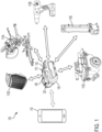
FIG. 1 illustrates acommunication system 100 including variouspower tool devices 110 powered by abattery pack 120. Thesystem 100 also includes amobile device 130 that can control thepower tool devices 110 through thebattery pack 120. Thepower tool devices 110 may include motorized power tool devices (for example, a miter saw 110A, a drill-driver 1 10B, ashop vacuum 110C, and the like) or non-motorized electrical devices (for example, awork radio 110D, awork light 110E, and the like). Each of thepower tool devices 110A-E may be individually referred to as thepower tool device 110, or collectively as thepower tool devices 110. At least in some embodiments, thepower tool devices 110 may be described as electrically powered devices that are configured to be coupled to and powered by a power tool battery pack (e.g., the battery pack 120) that is configured to be coupled to and power a motorized power tool (e.g., a drill, a saw, and the like). - The
battery pack 120 is a power tool battery pack having a nominal voltage of, for example, 12 Volts, 18 Volts, and the like. Thebattery pack 120 includes ahousing 140, atool interface 150, and alatch 160 controlled byactuator 170 to selectively latch thetool interface 150 to a battery interface of thepower tool 110. Themobile device 130 is a mobile communication device, for example, a smart telephone, a tablet computer, a laptop computer, a personal digital assistant, a smart wearable device (e.g., smart watch), and the like. - With reference to
FIG. 2 , thepower tool device 110 includes a toolelectronic processor 200, atool memory 205, andtool electronics 210. The toolelectronic processor 200 may be implemented as, for example, a microprocessor, a microcontroller, a field programmable gate array, an application specific integrated circuit, or the like. Thetool memory 205 may be a part of the toolelectronic processor 200 or may be a separate component. Thetool memory 205 may include, for example, a program storage area and a data storage area. Thetool memory 205 stores executable instructions that when executed by the toolelectronic processor 200, cause thepower tool device 110 to perform the functions described herein. For example, the toolelectronic processor 200 controls the functions of thepower tool device 110 and enables communication between thepower tool device 110 and thebattery pack 120. Thetool electronics 210 may include a switch bridge and a motor (not shown) when thepower tool device 110 is a motorized power tool and may include other electronics (e.g., LEDs, radio transceiver, speaker, and the like) when thepower tool device 110 is a non-motorized electronic device. Thetool electronics 210 are controlled by the toolelectronic processor 200. For example, the toolelectronic processor 200 is configured to one or more of enable thetool electronics 210, disable thetool electronics 210, and modify operating characteristics (e.g., motor power, LED brightness, radio tuning, speaker volume, and the like). - The
battery pack 120 includesbattery cells 215, a packelectronic processor 220, apack memory 225, and apack transceiver 230 within thehousing 140. The packelectronic processor 220, thepack memory 225, and thepack transceiver 230 communicate over one or more control and or data buses (for example, a communication bus 235). Thebattery cells 215 may be arranged in a series, parallel, or series-parallel combination. For example, thebattery cells 215 include one or more series strings of five cells connected in parallel. In some embodiments, thebattery cells 215 have a lithium-ion based chemistry and each provide approximately 3.6 nominal voltage. In other embodiments, thebattery cells 215 have different chemistry, voltage output, or both. Thebattery cells 215 provide operating power to the other components of thebattery pack 120. Additionally, operating power from thebattery cells 215 is provided to thepower tool device 110 overpower terminals 240. - The pack
electronic processor 220 may be implemented as, for example, a microprocessor, a microcontroller, a field programmable gate array, an application specific integrated circuit, or the like. Thepack memory 225 may be a part of the packelectronic processor 220 or may be a separate component. Thepack memory 225 may include, for example, a program storage area and a data storage area. Thepack memory 225 stores executable instructions that when executed by the packelectronic processor 220, cause thebattery pack 120 to perform the functions described herein. The packelectronic processor 220 communicates with the toolelectronic processor 200 over acommunication terminal 245 to exchange data and control signals. Thecommunication terminals 245 may implement a serial communication system for example, an RS-485 link or the like to facilitate communications between the packelectronic processor 220 and the toolelectronic processor 200. In some embodiments, rather than over thecommunication terminal 245, the packelectronic processor 220 and the toolelectronic processor 200 may communicate over near-field wireless communication link, for example, a Bluetooth® connection or the like. In such embodiments, thepower tool device 110 andbattery pack 120 include respective wireless transceivers to facilitate the wireless communications. - The
pack transceiver 230 facilitates communication between thebattery pack 120 and an external device, for example, themobile device 130 over a wireless communication network. In some embodiments, thepack transceiver 230 includes a combined transmitter-receiver component. In other embodiments, thepack transceiver 230 includes separate transmitter and receiver components. - The
power tool device 110 and thebattery pack 120 may include more or fewer components and may perform functions other than those described herein. - With reference to
FIG. 3 , themobile device 130 includes a deviceelectronic processor 310, adevice memory 320, adevice transceiver 330, and device input/output interface 340. The deviceelectronic processor 310, thedevice memory 320, thedevice transceiver 330, and the device input/output interface 340 communicate over one or more control and/or data buses (for example, a communication bus 350). Themobile device 130 may include more or fewer components and may perform functions other than those described herein. - The device
electronic processor 310 may be implemented as, for example, a microprocessor, a microcontroller, a field programmable gate array, an application specific integrated circuit, or the like. Thedevice memory 320 may store executable instructions that are executed by the deviceelectronic processor 310 to carry out the functionality of themobile device 130 described herein. - The
device transceiver 330 facilitates communication between themobile device 130 and an external device, for example, thebattery pack 120 over a wireless communication network. In some embodiments, thedevice transceiver 330 includes a combined transmitter-receiver component. In other embodiments, thedevice transceiver 330 includes separate transmitter and receiver components. Thedevice transceiver 330 is controlled by the deviceelectronic processor 310, for example, to transmit and receive data between themobile device 130 and thebattery pack 120. - The device input/
output interface 340 may include one or more input mechanisms (e.g., a keypad, a mouse, and the like), one or more output mechanisms (e.g., a display, a speaker, and the like), or a combination of the two (e.g., a touch screen, or the like). - The
mobile device 130 also includes amobile application 360, which is an application designed for a mobile operating system for use on themobile device 130. Thedevice memory 320 may store themobile application 360 and the deviceelectronic processor 310 executes themobile application 360 to enable themobile device 130 to carry out the functionality of themobile application 360 described herein. Themobile application 360 may communicate with thebattery pack 120 over a connection between themobile device 130 and thebattery pack 120. Themobile application 360 may include a graphical user interface in that, execution of themobile application 360 by the deviceelectronic processor 310 may generate a graphical user interface on a display (e.g., input/output interface 340) of themobile device 130. Themobile device 130 may convey information to a user through display of the graphical user interface and may receive user input via the graphical user interface (i.e., the input/output interface 340). - In some embodiments, the mobile device 130 (via the device transceiver 330) and the battery pack 120 (via the pack transceiver 230) communicate over a direct wireless connection, for example, a Bluetooth® connection, a ZigBee® connection, or the like. In other embodiments, the mobile device 130 (via the device transceiver 330) and the battery pack 120 (via the pack transceiver 230) communicate over an indirect wireless connection, for example, over a cellular network, over the Internet, or the like.
-
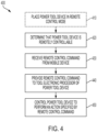
FIG. 4 is a flowchart illustrating anexemplary method 400 for remotely controlling thepower tool device 110. As illustrated inFIG. 4 , themethod 400 includes placing thepower tool device 110 in a remote control mode (at step 410). Thepower tool device 110 may include a mode switch (not shown) that can be actuated by a user to select a mode of thepower tool device 110. For example, the mode switch may be between a first position for selecting the remote control mode and a second position for selecting a normal mode (i.e., deselecting the remote control mode) by the user. The toolelectronic processor 200 receives position information of the mode switch and places thepower tool device 110 in the selected mode. Particularly, the toolelectronic processor 200 determines that the mode switch is in the first position and places thepower tool device 110 in the remote control mode. When thepower tool device 110 is in the remote control mode, thepower tool device 110 can be remotely controlled by themobile device 130 as described below. When thepower tool device 110 is in the normal mode, thepower tool device 110 ignores (e.g., discards) commands received from themobile device 130 without executing the received commands. - The
method 400 also includes determining, by the packelectronic processor 220, that thepower tool device 110 is remotely controllable (at step 420). The remote control feature may not be provided on everypower tool device 110 configured to be coupled to and powered by thebattery pack 120. For example, the remote control feature may be provided on thework radio 110D, thework light 110E, and theshop vacuum 110C, but may not be provided on the miter saw 110A or the drill-driver 11 0B. In some embodiments, the packelectronic processor 220 determines whether thepower tool device 110 is remotely controllable using identification signals received from thepower tool device 110. For example, the toolelectronic processor 200 communicates identification signals over thecommunication terminal 245 to the packelectronic processor 220. - The identification signals may include for example, a type of the power tool (e.g., by model number), which is then used by the pack
electronic processor 220 to access and retrieve from a lookup table an indication of whether thepower tool device 110 is remotely controllable. The lookup table may be on the stored on thepack memory 225, thedevice memory 320, or a combination thereof. In some embodiments, the identification signals include an explicit indication of whether thepower tool device 110 is remotely controllable or not remotely controllable. - In some embodiments, the
battery pack 120 includes a sensor in communication with the packelectronic processor 220 that is configured to detect whether thepower tool device 110 is remotely controllable. For example, the sensor of thebattery pack 120 may be a Hall effect sensor configured to detect a magnetic field, and thepower tool device 110 that is remotely controllable may include a magnet near its battery pack interface. Upon coupling thepower tool device 110 and thebattery pack 120, the sensor provides an output to the packelectronic processor 220 indicative of the presence (or absence) of the magnet or indicative of the pole orientation of the magnet, and the output is indicative of whether thepower tool device 110 is remotely controllable. Accordingly,power tool devices 110 having no such magnet, or having a magnet with a pole orientation representing that the device is not remotely controllable, are determined by the packelectronic processor 220 to be not remotely controllable.Power tool devices 110 having a magnet, or having a magnet with a pole orientation representing that the device is remotely controllable, are determined by the packelectronic processor 220 to be remotely controllable. - The
method 400 further includes receiving, by the packelectronic processor 220, a remote control command from the mobile device 130 (at step 430). The remote control command can be a command to, for example, turn the power tool device ON/OFF, activate a motor of the power tool device, switch an LED ON/OFF, adjust a radio station tuning, adjust an LED brightness, adjust a speaker volume, adjust a motor speed, and the like. The command can be selected on a graphical user interface of themobile application 360. Thebattery pack 120 may communicate the type or identification information of thepower tool device 110 connected to thebattery pack 120 to themobile device 130. Themobile device 130 may display a list of commands a user can select on the graphical user interface of themobile application 360. When themobile device 130 receives a selection of the remote control command from the list of commands (e.g., based on user input received by the device input/output interface 340), themobile device 130 transmits the remote control command to thebattery pack 120 via thedevice transceiver 330. Particularly, the packelectronic processor 220 receives the remote control command wirelessly via thepack transceiver 230. - The method also includes providing, by the pack
electronic processor 220, the remote control command to the toolelectronic processor 200 of the power tool device 110 (at step 440). The packelectronic processor 220 relays the command received from themobile device 130 to the toolelectronic processor 200. As described above, the packelectronic processor 220 and the toolelectronic processor 200 communicate over thecommunication terminal 245 or over a near-field communication link. The packelectronic processor 220 provides the remote control command to the toolelectronic processor 200 via thecommunication terminal 245 or the near-field communication link. In some embodiments, the packelectronic processor 220 may provide remote control command in response to determining that thepower tool device 110 is remotely controllable, that thepower tool device 110 is in a remote control mode, or both. - The
method 400 further includes controlling, by the toolelectronic processor 200, thepower tool device 110 to perform an action specified by the remote control command (at step 450). The toolelectronic processor 200, in response to receiving the remote control command, controls thetool electronics 210 to perform the action specified by the remote control command. For example, the toolelectronic processor 200 turns the power tool device ON/OFF, activates a motor of the power tool device, switches an LED ON/OFF, adjusts a radio station tuning, adjusts an LED brightness, adjusts a speaker volume, adjusts a motor speed, and the like. In some embodiments, thepower tool device 110 operates in a lower power draw mode until a remote control command is received from thebattery pack 120. In the low power draw mode, the power draw is sufficient to maintain communication with thebattery pack 120 and monitor for remote control commands, but not sufficient to perform the actions specified by the remote control command. Upon receiving the remote control command, the toolelectronic processor 200 switches thepower tool device 110 to the high power draw mode to perform the action specified by the remote control command. - While the steps of the
method 400 are illustrated in a particular serial order, in some embodiments, one or more of the steps are executed in parallel or in a different order than illustrated. For example, one or both ofsteps step 430. -
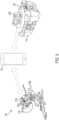
FIG. 5 illustrates oneexample system 500 for implementing a remote controlling ofpower tool devices 110. Thesystem 500 includes the miter saw 110A (for example, a first power tool device) connected to afirst battery pack 120A, theshop vacuum 110C (for example, a second power tool device) connected to asecond battery pack 120B, and themobile device 130. Thefirst battery pack 120A and thesecond battery pack 120B are examples of thebattery pack 120 described above. Accordingly, the description provided above with respect to thebattery pack 120 similarly applies to thefirst battery pack 120A and thesecond battery pack 120B. Themobile device 130 wirelessly communicates with thefirst battery pack 120A and thesecond battery pack 120B as described above. - When the miter saw 110A is operated on a workpiece, the resulting cut may create dust that is deposited on the work bench. Users may use the
shop vacuum 110C to clear the dust deposited by the miter saw 110A. However, the user may have to pause the current cut to vacuum excess dust, or operate the vacuum between successive cuts to clear dust. This dust removal may result in a user taking additional time to complete a project. In some embodiments, ahose 505 of theshop vacuum 110C is directly coupled to adust port 510 of the miter saw 110A. Thedust port 510 includes adust intake end 515 near the saw blade to extract dust during a cut and a dust exhaust end, opposite thedust intake end 515, to expel extracted dust into thehose 505 coupled to the dust port. Still, users may need to manually turn on and off theshop vacuum 110 with each cut, or leave theshop vacuum 110 enabled between cuts despite a lack of dust needing extraction between cuts. - The dust collection process can be automated to be more efficient and to speed up the project by remotely controlling the
shop vacuum 110C while the miter saw 110A is being operated.FIG. 6 is a flowchart illustrating anexemplary method 600 for automating dust collection during operation of a miter saw 110A. As illustrated inFIG. 6 , themethod 600 includes determining, by the deviceelectronic processor 310, that the miter saw 110A (i.e., the first power tool device 110) is being operated (at step 610). For example, a pack electronic processor of thefirst battery pack 120A detects a power draw when the user operates the miter saw 110A, for example, using a current sensor electrically connected to the power terminals of thefirst battery pack 120A. The pack electronic processor of thefirst battery pack 120A sends a signal, via the pack transceiver, indicating that the miter saw 110A is being operated to themobile device 130 in response to detecting the power draw. The deviceelectronic processor 310 of themobile device 130 determines that the miter saw 110A is being operated upon receiving this signal from thefirst battery pack 120A. - The
method 600 also includes providing, by the deviceelectronic processor 310, a remote control command to thesecond battery pack 120B in response to the determination that the miter saw 110A is being operated (at step 620). For example, in response to determining that the miter saw 110A is being operated, the deviceelectronic processor 310 transmits the remote control command via thedevice transceiver 330, and the remote command is received by thesecond battery pack 120B. The remote control command is a request to turn theshop vacuum 110C (i.e., the second power tool 110) ON (i.e., to activate a motor of theshop vacuum 110C). - The method further includes controlling the shop vacuum to turn ON in response to the remote control command received by the
second battery pack 120B (at step 630). For example, the packelectronic processor 220 of thesecond battery pack 120B relays the remote control command to the toolelectronic processor 200 of theshop vacuum 110C. In response to the remote control command, the toolelectronic processor 200 of theshop vacuum 110C switches theshop vacuum 110 from the low power draw mode to the high power draw mode and activates the motor of theshop vacuum 110C. Accordingly, theshop vacuum 110C may be operated essentially simultaneously with the miter saw 110A without any user intervention. In other words, when the miter saw 110A is activated by the user, theshop vacuum 110C is activated. This allows the dust collection process to be automated, which saves time for the user and provided a more efficient dust extraction. - In some embodiments, a similar technique is used to deactivate the
shop vacuum 110C in response to deactivation of the miter saw 110 by the user. For example, afterstep 630, the deviceelectronic processor 310 determines that the miter saw 110A (i.e., the first power tool device 110) has ceased being operated. For example, the packelectronic processor 220 of thefirst battery pack 120A detects a lack of power draw by the miter saw 110A in response to the user releasing a trigger of the saw. In turn, the packelectronic processor 220 of thefirst battery pack 120A sends a signal, via the pack transceiver, indicating that the miter saw 110A has ceased being operated to the mobile device. In response to receiving the signal, the deviceelectronic processor 310 of themobile device 130 determines that the miter saw 110A has ceased being operated. - Further, the device
electronic processor 310 provides a second remote control command to thesecond battery pack 120B in response to the determination that the miter saw 110A has ceased being operated. For example, in response to determining that the miter saw 110A has ceased being operated, the deviceelectronic processor 310 transmits the second remote control command via thedevice transceiver 330, and the second remote command is received by thesecond battery pack 120B. The second remote control command is a request to turn theshop vacuum 110C (i.e., the second power tool 110) OFF (i.e., to deactivate a motor of theshop vacuum 110C). - Further, the shop vacuum is controlled to turn OFF in response to the second remote control command received by the
second battery pack 120B. For example, the packelectronic processor 220 of thesecond battery pack 120B relays the second remote control command to the toolelectronic processor 200 of theshop vacuum 110C. In response to the remote control command, the toolelectronic processor 200 of theshop vacuum 110C switches theshop vacuum 110 from the high power draw mode to the low power draw mode and deactivates the motor of theshop vacuum 110C. Accordingly, theshop vacuum 110C may be enabled and disabled essentially simultaneously with the miter saw 110A without any user intervention. In other words, when the miter saw 110A is activated by the user, theshop vacuum 110C is activated, and when the miter saw 110A is deactivated by the user, theshop vacuum 110C is deactivated. This allows the dust collection process to be automated, which saves time for the user and provided a more efficient dust extraction. - In some embodiments, the
first battery pack 120A and thesecond battery pack 120B communicate directly bypassing themobile device 130. Themobile device 130 may be used to communicatively connect thefirst battery pack 120A and thesecond battery pack 120B. Themobile device 130 may be used to pair (for example, Bluetooth® pairing) thefirst battery pack 120A with thesecond battery pack 120B. For example, a connection may be initiated using a graphical user interface (GUI) of a software application executing on themobile device 130. In this example, themobile device 130 may detect that the battery packs 120A, 120B in wireless communication range; display an identifier for the battery packs 120A, 120B on the GUI; and allow a user to select on the GUI thefirst battery pack 120 and thesecond battery pack 120B for pairing with each another. To pair thefirst battery pack 120A with thesecond battery pack 120B, themobile device 130 may provide identification information, connection identification information, and/or password information for the connection to each of thefirst battery pack 120A and thesecond battery pack 120B. Thefirst battery pack 120A and thesecond battery pack 120B use the identification information, connection information, and/or password information to subsequently establish a communication link or to communicate with each other. Particularly, thefirst battery pack 120A and thesecond battery pack 120B communicate directly to implement themethod 600 as provided above. - Thus, embodiments described herein provide, among other things, a system and method for remote control of a power tool device.
Claims (13)
- A system (100, 500) for remote controlling a power tool device (110, 110A) comprising:a power tool device (110, 110A) including a tool electronic processor (200); anda battery pack (120, 120A) coupled to the power tool device (110, 110A),characterised bythe battery pack (120, 120A) including a pack transceiver (230),a pack electronic processor (220) coupled to the pack transceiver (230) and in communication with the tool electronic processor (200), the pack electronic processor (220) configured to determine that the power tool device (110, 110A) is remotely controllable, receive, wirelessly via the pack transceiver (230), a remote control command from a mobile device (130), provide the remote control command to the power tool device (110, 110A),wherein the tool electronic processor (200) is configured to control the power tool device (110, 110A) to perform an action specified by the remote control command in response to receiving the remote control command from the pack electronic processor (220),and wherein the tool electronic processor (200) is further configured to place the power tool device (110, 110A) in a remote control mode in response to receiving a user input.
- The system (100, 500) of claim 1, wherein the power tool device further includes a mode switch switchable between a first position for selecting a remote control mode and a second position for selecting a normal mode, wherein the tool electronic processor places the power tool device in the remote control mode in response to a user placing the mode switch in the first position.
- The system (100, 500) of claim 1 or 2, further comprisinga second power tool device (110, 110C), wherein the pack electronic processor (220) is further configured to determine that the second power tool device is not remotely controllable when the battery pack is coupled to the second power tool device,or further comprisinga second power tool device; anda second battery pack (120, 120B) coupled to the second power tool device, the second battery pack includinga second pack transceiver (230),a second pack electronic processor (220) coupled to the second pack transceiver, the pack electronic processor configured to detect that the second power tool device is being operated, and provide, via the second pack transceiver, an indication that the second power tool device is being operated to the mobile device.
- The system (100, 500) of claim 3, wherein the mobile device (130) provides the remote control command in response to receiving the indication from the second pack electronic processor (220), wherein the action specified by the remote control command is to turn on the power tool device (110, 110A).
- The system (100, 500) of claim 3 or 4, wherein the second pack electronic processor (220) is further configured to detect that the second power tool device (110, 110C) has ceased being operated, and
provide, via the second pack transceiver (230), a second indication that the second power tool device has ceased being operated to the mobile device (130). - The system (110, 110C) of claim 5, wherein the mobile device (130) provides a second remote control command to the pack electronic processor (220) in response to receiving the second indication from the second pack electronic processor (220), andoptionally wherein the pack electronic processor is further configured to receive, wirelessly via the pack transceiver (230), the second remote control command from the mobile device, provide the second remote control command to the power tool device (110, 110A),wherein the tool electronic processor (200) is configured to control the power tool device to turn off in response to receiving the second remote control command from the pack electronic processor.
- A method for remote controlling a power tool device (110, 110A) powered by a battery pack (120, 120A), the method comprising:determining, by a pack electronic processor (220) of the battery pack, that the power tool device is remote controllable,receiving, wirelessly via a pack transceiver (230) of the battery pack, a remote control command from a mobile device (130),providing, using the pack electronic processor, the remote control command to a tool electronic processor (200) of the power tool device,controlling, using the tool electronic processor, the power tool device to perform an action specified by the remote control device in response to the tool electronic processor receiving the remote control command, and placing, using the tool electronic processor (200), the power tool device (110, 110A) in a remote control mode in response to a user input.
- The method of claim 7, wherein the power tool device includes a mode switch switchable between a first position for selecting a remote control mode and a second position for selecting a normal mode, the method further comprising:detecting, using the tool electronic processor, that the mode switch is in the first position, wherein placing the power tool device in the remote control mode is performed in response to detecting that the mode switch is in the first position, andoptionally further comprising determining, by the pack electronic processor (220), that a second power tool device (110, 110C) is not remotely controllable when the battery pack is coupled to the second power tool device.
- The method of claim 7 or 8, wherein a second power tool device (110, 110C) is coupled to a second battery pack (120, 120B), the method further comprising:detecting, using a second pack electronic processor (220) of the second battery pack, that the second power tool device is being operated, andproviding, via a second pack transceiver (230) of the second battery pack, an indication that the second power tool device is being operated to the mobile device (130).
- The method of claim 9, wherein the mobile device (130) provides the remote control command in response to receiving the indication from the second pack electronic processor (220), wherein the action specified by the remote control command is to turn on the power tool device (110, 110A).
- The method of claim 9 or 10, further comprising:detecting, using the second pack electronic processor (220), that the second power tool device (110, 110C) has ceased being operated, andproviding, via the second pack transceiver (230), a second indication that the second power tool device has ceased being operated to the mobile device (130).
- The method of claim 11, further comprising:
providing, using the mobile device (130), a second remote control command to the pack electronic processor (220) in response to receiving the second indication from the second pack electronic processor (220). - The method of claim 12, further comprising:receiving, wirelessly via the pack transceiver (230), the second remote control command from the mobile device (130),providing, using the pack electronic processor (220), the second remote control command to the tool electronic processor (200) of the power tool device (110, 110A), andcontrolling, using the tool electronic processor, the power tool device to turn off the second power tool device in response to the tool electronic processor receiving the remote control command.
Applications Claiming Priority (1)
| Application Number | Priority Date | Filing Date | Title |
|---|---|---|---|
| US201862712473P | 2018-07-31 | 2018-07-31 |
Publications (2)
| Publication Number | Publication Date |
|---|---|
| EP3603897A1 EP3603897A1 (en) | 2020-02-05 |
| EP3603897B1 true EP3603897B1 (en) | 2024-03-06 |
Family
ID=67514366
Family Applications (1)
| Application Number | Title | Priority Date | Filing Date |
|---|---|---|---|
| EP19189302.3A Active EP3603897B1 (en) | 2018-07-31 | 2019-07-31 | Systems and methods for remote power tool device control |
Country Status (6)
| Country | Link |
|---|---|
| US (4) | US11011053B2 (en) |
| EP (1) | EP3603897B1 (en) |
| CN (1) | CN210983054U (en) |
| AU (1) | AU2019100839A6 (en) |
| CA (1) | CA3050762A1 (en) |
| MX (1) | MX2019009092A (en) |
Families Citing this family (5)
| Publication number | Priority date | Publication date | Assignee | Title |
|---|---|---|---|---|
| CA3050762A1 (en) | 2018-07-31 | 2020-01-31 | Tti (Macao Commercial Offshore) Limited | Systems and methods for remote power tool device control |
| GB2611434B (en) * | 2018-11-28 | 2023-10-04 | Lawrence Fowler Robert | A power tool system |
| US11571803B2 (en) * | 2019-05-30 | 2023-02-07 | Milwaukee Electric Tool Corporation | Power tool with combined chip for wireless communications and power tool control |
| AT523566A1 (en) * | 2020-03-10 | 2021-09-15 | Weber Hyraulik Gmbh | Method for operating a rescue system with a mobile rescue device |
| MX2021014829A (en) * | 2020-12-11 | 2022-07-12 | Techtronic Cordless Gp | Method of estimating a state-of-charge of a battery pack. |
Citations (1)
| Publication number | Priority date | Publication date | Assignee | Title |
|---|---|---|---|---|
| US20160311094A1 (en) * | 2013-10-21 | 2016-10-27 | Milwaukee Electric Tool Corporation | Adapter for power tool devices |
Family Cites Families (203)
| Publication number | Priority date | Publication date | Assignee | Title |
|---|---|---|---|---|
| US3626545A (en) | 1969-10-09 | 1971-12-14 | Perry W Sparrow | Central vacuum cleaner with remote control |
| JPS5828110B2 (en) | 1978-10-19 | 1983-06-14 | 日立造船株式会社 | Lower corrugated roll in single-sided corrugated board manufacturing machine |
| GB2038615B (en) | 1978-12-31 | 1983-04-13 | Nintendo Co Ltd | Self-moving type vacuum cleaner |
| DE8808570U1 (en) | 1988-07-05 | 1988-09-08 | Bsg-Schalttechnik Gmbh & Co Kg, 7460 Balingen, De | |
| DE3822633A1 (en) | 1988-07-05 | 1990-01-18 | Bsg Schalttechnik | DEVICE WITH AUTOMATIC SWITCH-ON FOR A SUB-DEVICE WHEN STARTING A MAIN DEVICE |
| DE3839932A1 (en) | 1988-11-26 | 1990-05-31 | Festo Kg | POWER SUPPLY UNIT |
| JP2553485Y2 (en) | 1991-04-19 | 1997-11-05 | 株式会社マキタ | External power supply mechanism for dust collector |
| US5274878A (en) | 1991-07-23 | 1994-01-04 | Cen-Tec Systems Inc. | Remote control system for central vacuum systems |
| US7613590B2 (en) | 1992-11-17 | 2009-11-03 | Health Hero Network, Inc. | Modular microprocessor-based power tool system |
| US6424799B1 (en) | 1993-07-06 | 2002-07-23 | Black & Decker Inc. | Electrical power tool having a motor control circuit for providing control over the torque output of the power tool |
| JPH07222756A (en) | 1994-02-14 | 1995-08-22 | Ricoh Elemex Corp | Dust collecting device with illumination for medical-use |
| US5606767A (en) | 1995-05-19 | 1997-03-04 | Crlenjak; Jack | Vacuum operated dust and debris removal and collection system |
| CA2175268C (en) | 1995-12-07 | 2001-11-20 | George E. Hendrix | Portable electric tool vacuum cleaner control |
| KR970032722A (en) | 1995-12-19 | 1997-07-22 | 최진호 | Cordless cleaner |
| US5709007A (en) | 1996-06-10 | 1998-01-20 | Chiang; Wayne | Remote control vacuum cleaner |
| KR0175512B1 (en) | 1996-09-30 | 1999-02-18 | 배순훈 | Vacuum cleaner |
| US5903462A (en) | 1996-10-17 | 1999-05-11 | The United States Of America As Represented By The Administrator Of The National Aeronautics And Space Administration | Computer implemented method, and apparatus for controlling a hand-held tool |
| US6967972B1 (en) | 1997-07-31 | 2005-11-22 | Cisco Technology, Inc. | Universal protocol conversion |
| US6058071A (en) * | 1998-08-10 | 2000-05-02 | The United States Of America As Represented By The Secretary Of The Navy | Magneto-inductive submarine communications system and buoy |
| US6339735B1 (en) | 1998-12-29 | 2002-01-15 | Friendly Robotics Ltd. | Method for operating a robot |
| US6675196B1 (en) | 1999-01-08 | 2004-01-06 | Amazon.Com, Inc. | Universal protocol for enabling a device to discover and utilize the services of another device |
| US6536536B1 (en) | 1999-04-29 | 2003-03-25 | Stephen F. Gass | Power tools |
| US6222285B1 (en) | 1999-09-07 | 2001-04-24 | Shop Vac Corporation | Intelligent switch control circuit |
| JP2001137158A (en) | 1999-11-10 | 2001-05-22 | Matsushita Electric Ind Co Ltd | Central cleaner |
| JP2001161607A (en) | 1999-12-10 | 2001-06-19 | Matsushita Electric Ind Co Ltd | Central cleaner |
| US7721006B2 (en) | 1999-12-30 | 2010-05-18 | Bally Gaming, Inc. | Meta-message set with real-time and database aspects |
| US7369635B2 (en) | 2000-01-21 | 2008-05-06 | Medtronic Minimed, Inc. | Rapid discrimination preambles and methods for using the same |
| EP1769887B1 (en) | 2000-03-16 | 2008-07-30 | Makita Corporation | Power tools |
| DE10029133A1 (en) | 2000-06-14 | 2002-01-03 | Hilti Ag | Electric hand tool device with tool |
| US7200671B1 (en) | 2000-08-23 | 2007-04-03 | Mks Instruments, Inc. | Method and apparatus for monitoring host to tool communications |
| AT411312B (en) | 2000-10-20 | 2003-11-25 | Universal Comm Platform Ag | METHOD FOR TRANSMITTING SHORT MESSAGES (SMS) BETWEEN COMPUTERS ON THE INTERNET |
| JP2002209818A (en) | 2001-01-19 | 2002-07-30 | Toshiba Tec Corp | Vacuum cleaner |
| JP4021625B2 (en) | 2001-02-01 | 2007-12-12 | 株式会社マキタ | Dust collector and electric tool |
| DE10112129A1 (en) | 2001-03-14 | 2002-09-19 | Hilti Ag | Intake module |
| US6671583B2 (en) | 2001-03-30 | 2003-12-30 | Helix Technology Corporation | Vacuum system information network |
| KR100725516B1 (en) | 2001-04-18 | 2007-06-08 | 삼성광주전자 주식회사 | Robot cleaning System |
| KR100437372B1 (en) | 2001-04-18 | 2004-06-25 | 삼성광주전자 주식회사 | Robot cleaning System using by mobile communication network |
| US20030033686A1 (en) | 2001-08-07 | 2003-02-20 | Te-Hsi Liu | Dust collecting apparatus for eraser |
| US7155618B2 (en) | 2002-03-08 | 2006-12-26 | Freescale Semiconductor, Inc. | Low power system and method for a data processing system |
| US8004664B2 (en) | 2002-04-18 | 2011-08-23 | Chang Type Industrial Company | Power tool control system |
| US7054696B2 (en) | 2002-07-18 | 2006-05-30 | Black & Decker Inc. | System and method for data retrieval in AC power tools via an AC line cord |
| US7296323B2 (en) | 2002-08-21 | 2007-11-20 | Hitachi Koki Co., Ltd. | Dust collector |
| US7146677B2 (en) | 2002-11-19 | 2006-12-12 | Ivan Litomisky | Energy saving vacuum system for particle, mist, and fume collection |
| JP4550357B2 (en) | 2002-12-16 | 2010-09-22 | 株式会社マキタ | Dust collector interlocking system |
| DE10303006B4 (en) | 2003-01-27 | 2019-01-03 | Hilti Aktiengesellschaft | Hand-held implement |
| JP4329369B2 (en) | 2003-03-20 | 2009-09-09 | パナソニック電工株式会社 | Power tool usage support method and apparatus |
| US6898542B2 (en) | 2003-04-01 | 2005-05-24 | Fisher-Rosemount Systems, Inc. | On-line device testing block integrated into a process control/safety system |
| KR200321249Y1 (en) | 2003-04-19 | 2003-07-28 | 오토사이언스(주) | Wireless remote control wireless vacuum cleaner |
| DE10319022B4 (en) | 2003-04-28 | 2009-10-15 | Fette Gmbh | Plant for the production of tablets |
| US7646155B2 (en) | 2003-04-30 | 2010-01-12 | Balck & Decker Inc. | Generic motor control system |
| US7102303B2 (en) | 2003-04-30 | 2006-09-05 | Black & Decker Inc. | Generic motor control system and method |
| US6851900B2 (en) | 2003-06-09 | 2005-02-08 | Python Perfect Cutter, Inc. | Hole cutting tool |
| US7330129B2 (en) | 2003-07-16 | 2008-02-12 | Black & Decker Inc. | System and method for data retrieval in AC power tools via an AC line cord |
| JP2005102791A (en) | 2003-09-29 | 2005-04-21 | Hitachi Koki Co Ltd | Dust collector |
| JP2005157551A (en) | 2003-11-21 | 2005-06-16 | Canon Inc | Electronic apparatus, and control method thereof |
| ES2280888T3 (en) | 2003-11-24 | 2007-09-16 | Black & Decker Inc. | WIRELESS SYSTEM FOR MONITORING AND SECURITY OF PROPERTY. |
| US6913087B1 (en) | 2004-01-30 | 2005-07-05 | Black & Decker Inc. | System and method for communicating over power terminals in DC tools |
| US6845279B1 (en) | 2004-02-06 | 2005-01-18 | Integrated Technologies, Inc. | Error proofing system for portable tools |
| DE102004016171A1 (en) | 2004-03-30 | 2005-10-20 | Bosch Gmbh Robert | Hand tool |
| JP2005296510A (en) | 2004-04-15 | 2005-10-27 | Funai Electric Co Ltd | Self-traveling vacuum cleaner with monitor camera |
| US6856113B1 (en) | 2004-05-12 | 2005-02-15 | Cube Investments Limited | Central vacuum cleaning system motor control circuit mounting post, mounting configuration, and mounting methods |
| US20050279213A1 (en) | 2004-06-18 | 2005-12-22 | Otto John E | Method and apparatus for controlling the operation of a dust collector |
| US20090024757A1 (en) | 2004-07-30 | 2009-01-22 | Proctor David W | Automatic Protocol Determination For Portable Devices Supporting Multiple Protocols |
| US7298240B2 (en) * | 2004-09-24 | 2007-11-20 | David Lamar | Electronically enabling devices remotely |
| WO2006044693A2 (en) | 2004-10-18 | 2006-04-27 | Black & Decker Inc. | Cordless power system |
| KR100645379B1 (en) | 2004-10-29 | 2006-11-15 | 삼성광주전자 주식회사 | A robot controlling system and a robot control method |
| US8005647B2 (en) | 2005-04-08 | 2011-08-23 | Rosemount, Inc. | Method and apparatus for monitoring and performing corrective measures in a process plant using monitoring data with corrective measures data |
| US7253577B2 (en) | 2005-05-20 | 2007-08-07 | Rockwell Automation Technologies, Inc. | Independent safety processor for disabling the operation of high power devices |
| US20060293788A1 (en) | 2005-06-26 | 2006-12-28 | Pavel Pogodin | Robotic floor care appliance with improved remote management |
| JP4515359B2 (en) | 2005-08-31 | 2010-07-28 | 鹿島建設株式会社 | Dust collector operation control device |
| WO2007057037A1 (en) * | 2005-11-18 | 2007-05-24 | Metabowerke Gmbh | Electric hand tool device and battery pack therefor |
| CA2535299C (en) | 2006-02-06 | 2014-07-22 | Dan Provost | Method for applying preset torques to threaded fasteners and a power tool therefor |
| JP4916266B2 (en) | 2006-04-10 | 2012-04-11 | トヨタホーム株式会社 | Building with dust collector |
| US20070283521A1 (en) | 2006-06-09 | 2007-12-13 | Electrolux Home Care Products Ltd. | Electronic control system for a vacuum system |
| JP2008000739A (en) | 2006-06-21 | 2008-01-10 | Shinroku Nishiyama | Local dust collection system equipped with branch dust collection function |
| US20080022479A1 (en) | 2006-06-30 | 2008-01-31 | Kong Zhao | Power tool combination and synchronization control device |
| KR100833125B1 (en) | 2006-07-11 | 2008-05-28 | 이재영 | Control method for concentrated cleaning of cleaning robot |
| US7825627B2 (en) | 2006-07-17 | 2010-11-02 | O2Micro International Limited | Monitoring battery cell voltage |
| JP4955332B2 (en) | 2006-08-01 | 2012-06-20 | 株式会社マキタ | Dust collector interlocking system |
| DE102006038278B4 (en) | 2006-08-16 | 2022-02-17 | Andreas Stihl Ag & Co. Kg | Portable, hand-held tool with a data connection for diagnostics |
| US7822802B2 (en) | 2006-09-29 | 2010-10-26 | Fisher-Rosemount Systems, Inc. | Apparatus and method for merging wireless data into an established process control system |
| DE102006056834A1 (en) | 2006-12-01 | 2008-06-05 | Robert Bosch Gmbh | Electrical attachment to a power tool |
| SE530667C2 (en) | 2007-01-15 | 2008-08-05 | Atlas Copco Tools Ab | Portable power tool with wireless communication with a stationary controller |
| JP4876986B2 (en) | 2007-03-12 | 2012-02-15 | パナソニック株式会社 | Vacuum cleaner |
| US8750796B2 (en) | 2007-05-17 | 2014-06-10 | Abbott Medical Optics Inc. | Exclusive pairing technique for short-range communication devices |
| US8115448B2 (en) | 2007-06-01 | 2012-02-14 | Michael Sasha John | Systems and methods for wireless power |
| EP2003552A3 (en) | 2007-06-15 | 2009-08-19 | Black & Decker, Inc. | One fire boot loader |
| US20080311795A1 (en) | 2007-06-15 | 2008-12-18 | Brotto Daniele C | Adapter for cordless power tools |
| US7983789B2 (en) | 2007-09-14 | 2011-07-19 | Seagate Technology Llc | Collecting debris from a tool |
| JP2009083043A (en) | 2007-09-28 | 2009-04-23 | Panasonic Electric Works Co Ltd | Diagnostic system of power tool |
| CN201086970Y (en) | 2007-09-30 | 2008-07-16 | 王希哲 | Multifunctional intelligent cleaner |
| CN101234012A (en) | 2007-12-14 | 2008-08-06 | 陈宏乔 | Vacuum cleaner with wireless mobile monitoring function |
| US8443485B2 (en) | 2008-01-18 | 2013-05-21 | Black & Decker Inc. | Outlet box for power tool sense |
| US20090241283A1 (en) | 2008-01-21 | 2009-10-01 | Michael Loveless | Tool operated switch for vacuums |
| US8800103B2 (en) | 2008-02-28 | 2014-08-12 | Samsung Electronics Co., Ltd. | Upright type cleaner |
| KR20100006786A (en) | 2008-07-10 | 2010-01-21 | 삼성전자주식회사 | Upright type cleaner |
| EP2278699B1 (en) | 2008-02-29 | 2019-10-30 | Husqvarna AB | Electric saw communication |
| DE102008000973A1 (en) | 2008-04-03 | 2009-10-08 | Hilti Aktiengesellschaft | Hand-held implement |
| DE102008000974A1 (en) | 2008-04-03 | 2009-10-08 | Hilti Aktiengesellschaft | Portable container of a hand-held implement |
| DE102008000980B4 (en) | 2008-04-03 | 2011-04-28 | Hilti Aktiengesellschaft | Method for configuring a device electronics of a hand-held implement |
| US7827334B2 (en) | 2008-06-26 | 2010-11-02 | Triune Ip Llc | Protocol method apparatus and system for the interconnection of electronic systems |
| DE102009000102A1 (en) | 2009-01-09 | 2010-07-15 | Hilti Aktiengesellschaft | Control method for an accumulator and a hand tool |
| US9257865B2 (en) | 2009-01-22 | 2016-02-09 | Techtronic Power Tools Technology Limited | Wireless power distribution system and method |
| CN102292918A (en) | 2009-01-22 | 2011-12-21 | 创科电动工具科技有限公司 | Wireless power distribution system and method for power tools |
| US20100199453A1 (en) | 2009-02-09 | 2010-08-12 | Brotto Daniele C | Wireless particle collection system |
| US9198551B2 (en) | 2013-02-28 | 2015-12-01 | Omachron Intellectual Property Inc. | Surface cleaning apparatus |
| DE102009015642A1 (en) | 2009-03-21 | 2010-09-30 | Festool Gmbh | Suction device with function module |
| EP2233993B1 (en) | 2009-03-25 | 2012-10-10 | IVAT GmbH | Control construction box |
| DE102009029537A1 (en) | 2009-09-17 | 2011-03-31 | Robert Bosch Gmbh | Hand tool module |
| JP5740563B2 (en) | 2009-09-25 | 2015-06-24 | パナソニックIpマネジメント株式会社 | Electric tool |
| JP2011079082A (en) | 2009-10-06 | 2011-04-21 | Makita Corp | Dust collector interlocking system |
| DE102009046789A1 (en) | 2009-11-17 | 2011-05-19 | Robert Bosch Gmbh | Hand machine tool device |
| DE102009047443B4 (en) | 2009-12-03 | 2024-04-11 | Robert Bosch Gmbh | Hand tool machine |
| US8561623B2 (en) | 2009-12-08 | 2013-10-22 | Arnold Lowenstein | Apparatus for removing debris from gutters, troughs and other overhead open conduits |
| US8686685B2 (en) | 2009-12-25 | 2014-04-01 | Golba, Llc | Secure apparatus for wirelessly transferring power and communicating with one or more slave devices |
| JP5520095B2 (en) | 2010-03-16 | 2014-06-11 | パナソニック株式会社 | Wireless system |
| CN102283615A (en) | 2010-06-18 | 2011-12-21 | 苏州宝时得电动工具有限公司 | Dust collector |
| WO2012027739A2 (en) | 2010-08-27 | 2012-03-01 | Milwaukee Electric Tool Corporation | Thermal detection systems, methods, and devices |
| DE102010040336A1 (en) | 2010-09-07 | 2012-03-08 | Alfred Kärcher Gmbh & Co. Kg | Device and method for detecting a change in operating state of a power tool and vacuum cleaner |
| FR2965082B1 (en) | 2010-09-21 | 2012-09-28 | Inside Contactless | METHOD AND DEVICE FOR INDUCTIVE COUPLING ACTIVATED LOAD MODULATION |
| JP5618731B2 (en) | 2010-09-27 | 2014-11-05 | 株式会社マキタ | Dust collector |
| KR20120035047A (en) | 2010-10-04 | 2012-04-13 | 삼성전자주식회사 | Apparatus for secure pairing in wireless communication and method thereof |
| US20120100803A1 (en) | 2010-10-20 | 2012-04-26 | Nokia Corporation | Delayed and conditional transport switch |
| JP5593200B2 (en) | 2010-10-27 | 2014-09-17 | 株式会社マキタ | Electric tool system |
| WO2012061673A2 (en) | 2010-11-04 | 2012-05-10 | Ingersoll-Rand Company | Cordless power tools with a universal controller and tool and battery identification |
| DE102011105306A1 (en) | 2011-06-22 | 2012-12-27 | Robert Bosch Gmbh | Portable tool with wireless data transmission |
| JP5828110B2 (en) | 2011-06-22 | 2015-12-02 | パナソニックIpマネジメント株式会社 | Electric tool |
| US8874038B2 (en) | 2011-06-29 | 2014-10-28 | Broadcom Corporation | Secure communications via NFC device |
| CN103702803B (en) | 2011-07-24 | 2016-05-18 | 株式会社牧田 | For the theft of electric tool system hinder system with and adapter and method |
| WO2013014914A2 (en) | 2011-07-24 | 2013-01-31 | Makita Corporation | Adapter for power tools, power tool system and method of operating the same |
| EP2745569A4 (en) | 2011-09-14 | 2015-07-01 | Nokia Corp | A system, an apparatus, a device, a computer program and a method for devices with short range communication capabilities |
| US20130068255A1 (en) | 2011-09-19 | 2013-03-21 | Heger Research Llc | Automated dust collection system |
| WO2013063507A1 (en) * | 2011-10-26 | 2013-05-02 | Milwaukee Electric Tool Corporation | Wireless tracking of power tools and related devices |
| DE102011087361B3 (en) | 2011-11-29 | 2013-01-31 | Hilti Aktiengesellschaft | Suction device and control method |
| US9189663B2 (en) * | 2011-12-02 | 2015-11-17 | The Stanley Works Israel, Ltd | Battery operated device and tag for a battery operated tool |
| CN102490172B (en) | 2011-12-05 | 2014-09-24 | 东北林业大学 | Indoor intelligent cleaning robot |
| KR20140107434A (en) | 2011-12-12 | 2014-09-04 | 지멘스 악티엔게젤샤프트 | Method and devices for running push-button configuration sessions |
| DE102012003076A1 (en) | 2012-02-17 | 2013-08-22 | Festool Group Gmbh & Co. Kg | Suction device with a suction device transmitter and external communication device for it |
| DE102012003077A1 (en) | 2012-02-17 | 2013-08-22 | Festool Group Gmbh & Co. Kg | Identification method for a suction device and a hand-held machine tool |
| DE102012003073A1 (en) | 2012-02-17 | 2013-08-22 | Festool Group Gmbh & Co. Kg | Suction device for separating particle in suction flow from handheld machine tool, has suction communication device with suction channel to transmit leadless control signal and alarm signal to external communication device of hand tool |
| EP3524110A1 (en) | 2012-02-17 | 2019-08-14 | Festool GmbH | Suction device with a charger |
| US20130241699A1 (en) | 2012-03-19 | 2013-09-19 | Redwood Systems, Inc. | Device tracking with lighting system |
| US9837203B2 (en) | 2012-03-29 | 2017-12-05 | Integrated Device Technology, Inc. | Apparatuses having different modes of operation for inductive wireless power transfer and related method |
| JP6022201B2 (en) | 2012-05-07 | 2016-11-09 | シャープ株式会社 | REMOTE CONTROL SYSTEM, SETTING METHOD FOR THE REMOTE CONTROL SYSTEM, COMMUNICATION TERMINAL DEVICE, AND SERVER DEVICE |
| DE102012221997A1 (en) * | 2012-05-25 | 2013-11-28 | Robert Bosch Gmbh | power tool |
| US9740182B2 (en) | 2012-06-08 | 2017-08-22 | Applied Materials, Inc. | Integrated controller solution for monitoring and controlling manufacturing equipment |
| JP5915398B2 (en) | 2012-06-13 | 2016-05-11 | 株式会社リコー | Electric tool |
| US9055033B2 (en) | 2012-07-17 | 2015-06-09 | Milwaukee Electric Tool Corporation | Universal protocol for power tools |
| EP2687331B1 (en) | 2012-07-19 | 2015-03-04 | Guido Valentini | A vacuum cleaner connected to a hand held or hand guided tool and comprising a vibration monitoring device |
| JP2014057635A (en) | 2012-09-14 | 2014-04-03 | Toshiba Corp | Electric vacuum cleaner |
| CN203042139U (en) | 2012-10-30 | 2013-07-10 | 许佑正 | Suction force control device for dust collector |
| US9226372B2 (en) * | 2013-01-09 | 2015-12-29 | Raptor Inventions, Llc | Hands-free lighting system |
| US20140213179A1 (en) | 2013-01-29 | 2014-07-31 | Einar Rosenberg | System and Method for Establishing Communications between Two Devices |
| US9466198B2 (en) * | 2013-02-22 | 2016-10-11 | Milwaukee Electric Tool Corporation | Wireless tracking of power tools and related devices |
| US9108285B2 (en) | 2013-03-15 | 2015-08-18 | Black & Decker Inc. | Cord clamp current sensor for dust collector |
| JP6038715B2 (en) | 2013-04-10 | 2016-12-07 | 株式会社マキタ | Dust collector interlocking system |
| DE102013212003A1 (en) | 2013-06-25 | 2015-01-08 | Robert Bosch Gmbh | Hand tool |
| US10398452B2 (en) | 2013-06-26 | 2019-09-03 | Buffalo Filter, Llc | Method and system for vacuum suction |
| KR102099940B1 (en) | 2013-07-17 | 2020-04-13 | 삼성전자주식회사 | Method and apparatus for synchronization control in wireless power transfer system |
| EP3616839B1 (en) | 2013-08-02 | 2022-12-28 | Makita Corporation | Dust collector |
| DE102013018278A1 (en) | 2013-10-31 | 2015-04-30 | Metabowerke Gmbh | Multi-purpose vacuum cleaners |
| DE102013222313A1 (en) | 2013-11-04 | 2015-05-07 | Robert Bosch Gmbh | device system |
| DE102014209032A1 (en) | 2014-01-27 | 2015-07-30 | Robert Bosch Gmbh | Machine tool device |
| EP2937031A1 (en) | 2014-04-23 | 2015-10-28 | HILTI Aktiengesellschaft | Mode change |
| CN113472027A (en) | 2014-05-18 | 2021-10-01 | 百得有限公司 | Electric tool system |
| DE102014007402A1 (en) | 2014-05-20 | 2015-11-26 | Festool Gmbh | Hand machine tool with a particle removal port |
| CN106416202B (en) | 2014-06-04 | 2020-06-30 | 索诺瓦公司 | Audio device network and audio device pairing method |
| WO2016001209A1 (en) * | 2014-07-03 | 2016-01-07 | Atlas Copco Industrial Technique Ab | Method, nodes and computer program of a tool communications network |
| US9768475B2 (en) * | 2014-08-12 | 2017-09-19 | Apollo America Inc. | Battery pack containing communication electronics |
| US9958893B2 (en) | 2014-09-19 | 2018-05-01 | Sears Brands, L.L.C. | Method and system for enabling wireless control in tools by use of portable power supply systems with embedded communication components |
| EP3009058B1 (en) | 2014-10-13 | 2021-02-24 | Guido Valentini | Vacuum cleaner pneumatically connected to a power tool, method for controlling operation parameters of such a vacuum cleaner and power tool for pneumatic connection to such a vacuum cleaner |
| JP6408371B2 (en) | 2014-12-17 | 2018-10-17 | 株式会社マキタ | Electric tools and dust collectors |
| US20160317131A1 (en) * | 2015-04-29 | 2016-11-03 | Siemens Medical Solutions Usa, Inc. | Medical diagnostic imaging ultrasound probe battery pack radio |
| CN110213676B (en) * | 2015-05-04 | 2022-08-19 | 米沃奇电动工具公司 | Electric tool and wireless communication method |
| CN207096983U (en) * | 2015-06-16 | 2018-03-13 | 米沃奇电动工具公司 | The system and server of system including external equipment and server including electric tool and external equipment |
| US11440153B2 (en) | 2015-08-27 | 2022-09-13 | Hubbell Incorporated | Remotely activated portable hand tool |
| DE102015217180A1 (en) | 2015-09-09 | 2017-03-09 | Robert Bosch Gmbh | Portable energy storage device for supplying tools |
| US10345797B2 (en) * | 2015-09-18 | 2019-07-09 | Milwaukee Electric Tool Corporation | Power tool operation recording and playback |
| CN108476578B (en) * | 2015-10-30 | 2020-10-20 | 米沃奇电动工具公司 | Remote lighting control, configuration and monitoring |
| CN106896763B (en) * | 2015-12-17 | 2020-09-08 | 米沃奇电动工具公司 | System and method for configuring a power tool having an impact mechanism |
| CN108293037B (en) | 2015-12-25 | 2020-11-17 | 三菱电机株式会社 | Power supply device, power receiving device, power supply system, power supply method, and power management method |
| JP6697885B2 (en) | 2016-01-06 | 2020-05-27 | 株式会社マキタ | Electric work machine system |
| US20170201853A1 (en) * | 2016-01-09 | 2017-07-13 | Chervon (Hk) Limited | Power tool system |
| US10735467B2 (en) | 2016-01-11 | 2020-08-04 | Lg Electronics Inc. | Method and apparatus for controlling a device using bluetooth technology |
| TWM554386U (en) * | 2016-02-03 | 2018-01-21 | 米沃奇電子工具公司 | Power tool and power tool communication system |
| WO2017151045A1 (en) * | 2016-03-01 | 2017-09-08 | Husqvarna Ab | Wearable apparatus and system for use with outdoor power equipment |
| EP3436881B1 (en) | 2016-03-31 | 2022-07-27 | Husqvarna AB | Industrial automated vacuum cleaner and method for automated servicing of construction tools |
| US20170326696A1 (en) * | 2016-05-11 | 2017-11-16 | Daryll Halverson | Remote control power tool and method |
| DE102016111876A1 (en) | 2016-06-29 | 2018-01-04 | Metabowerke Gmbh | Portable device |
| DE102016113579A1 (en) | 2016-07-22 | 2018-01-25 | Metabo-Werke GmbH | Adapter assembly system |
| CN106385661B (en) | 2016-08-31 | 2019-09-20 | 泰凌微电子(上海)有限公司 | Pairing request, pairing response method and pairing request, pairing response terminal |
| JP6808450B2 (en) | 2016-11-04 | 2021-01-06 | 株式会社マキタ | Communication adapter mounting device and electric work machine |
| DE102017203685A1 (en) | 2017-03-07 | 2018-09-13 | Robert Bosch Gmbh | Method for operating a system |
| DE102017205072A1 (en) | 2017-03-27 | 2018-09-27 | Robert Bosch Gmbh | Suction device with plug-in module |
| CN106909156B (en) | 2017-03-30 | 2020-03-17 | 北京小米移动软件有限公司 | Air purification method and device |
| WO2018180896A1 (en) | 2017-03-31 | 2018-10-04 | 株式会社マキタ | Electric power tool |
| US10444720B2 (en) | 2017-07-05 | 2019-10-15 | Milwaukee Electrical Tool Corporation | Adapters for communication between power tools |
| DE202017104107U1 (en) | 2017-07-10 | 2017-07-30 | Metabowerke Gmbh | Use of a suction hose for user control |
| EP3664970A4 (en) * | 2017-08-07 | 2021-08-04 | Milwaukee Electric Tool Corporation | Power tool with irreversably lockable compartment |
| CN109421032B (en) | 2017-08-28 | 2023-12-22 | 创科电动工具科技有限公司 | Power tool system and method of operating the same |
| EP3528213A1 (en) | 2018-02-14 | 2019-08-21 | TTI (Macao Commercial Offshore) Limited | Method for controlling operation of non-autonomous electric garden tool |
| CA3050762A1 (en) * | 2018-07-31 | 2020-01-31 | Tti (Macao Commercial Offshore) Limited | Systems and methods for remote power tool device control |
| KR20200040533A (en) * | 2018-10-10 | 2020-04-20 | 삼성전자주식회사 | Battery managing bus-bar, manufacturing method thereof and battery management apparatus using the same |
-
2019
- 2019-07-29 CA CA3050762A patent/CA3050762A1/en active Pending
- 2019-07-29 US US16/524,970 patent/US11011053B2/en active Active
- 2019-07-30 CN CN201921217941.5U patent/CN210983054U/en active Active
- 2019-07-30 AU AU2019100839A patent/AU2019100839A6/en active Active
- 2019-07-31 MX MX2019009092A patent/MX2019009092A/en unknown
- 2019-07-31 EP EP19189302.3A patent/EP3603897B1/en active Active
-
2021
- 2021-04-21 US US17/236,442 patent/US11386774B2/en active Active
-
2022
- 2022-07-12 US US17/812,107 patent/US11890738B2/en active Active
-
2023
- 2023-12-21 US US18/392,617 patent/US20240123592A1/en active Pending
Patent Citations (1)
| Publication number | Priority date | Publication date | Assignee | Title |
|---|---|---|---|---|
| US20160311094A1 (en) * | 2013-10-21 | 2016-10-27 | Milwaukee Electric Tool Corporation | Adapter for power tool devices |
Also Published As
| Publication number | Publication date |
|---|---|
| EP3603897A1 (en) | 2020-02-05 |
| US11386774B2 (en) | 2022-07-12 |
| US11890738B2 (en) | 2024-02-06 |
| US20210241609A1 (en) | 2021-08-05 |
| MX2019009092A (en) | 2020-02-03 |
| AU2019100839A4 (en) | 2019-09-12 |
| US20200043321A1 (en) | 2020-02-06 |
| US11011053B2 (en) | 2021-05-18 |
| US20240123592A1 (en) | 2024-04-18 |
| AU2019100839A6 (en) | 2019-09-26 |
| CA3050762A1 (en) | 2020-01-31 |
| US20220351610A1 (en) | 2022-11-03 |
| CN210983054U (en) | 2020-07-10 |
Similar Documents
| Publication | Publication Date | Title |
|---|---|---|
| EP3603897B1 (en) | Systems and methods for remote power tool device control | |
| US11738426B2 (en) | Power tool communication system | |
| JP5879347B2 (en) | Universal wireless charging system for automobiles | |
| CN109491282A (en) | Debug load control system | |
| RU2010112999A (en) | MULTIFUNCTIONAL PORTABLE ELECTRIC TOOLS | |
| CN105684743A (en) | Garden device operating device | |
| CN110783977B (en) | Battery pack charging and discharging method and system of electric tool and battery pack | |
| KR20090066249A (en) | Arrangement, system and method for the wireless control of an apparatus | |
| CN205450753U (en) | Garage door control device | |
| CN105281412A (en) | Inductive energy transfer apparatus and method for position detection and/or presence detection by way of an inductive energy transfer apparatus | |
| CN109891701A (en) | Electrical equipment, power supply device, electric equipment system and managing device | |
| EP3517252A1 (en) | Motion monitoring device for handheld tool | |
| US11960265B2 (en) | Method for adapting an apparatus to a motor-driven tool, method for operating an apparatus in a type-dependent manner, apparatus for adaptation to a motor-driven tool, and system | |
| JP6806804B2 (en) | Methods and systems for wirelessly transmitting electronic data | |
| CN107081716A (en) | Convey the method from the communication between the conveying device of power driven tools, instrument and instrument and conveying device at instrument | |
| CN109297162B (en) | Temperature controller control method and system, mobile terminal and controlled temperature controller | |
| TW201817553A (en) | Electric power tool and method for controlling the same allows a user to change the setting of the electric power tool in a wireless manner to increase the flexibility of usage | |
| US20210353121A1 (en) | System Formed of Suction Device and Hand-Held Power Tool, and Method for Operating the System | |
| CN112512751A (en) | Electric working machine | |
| US20230296234A1 (en) | Externally controlled indicator | |
| US20230370011A1 (en) | Non-rotating location identification in power tools | |
| US10560895B2 (en) | Method for operating a mobile device and a data management system, mobile device, data management system | |
| CN112907862A (en) | Multifunctional microwave radar alarm | |
| WO2018091263A1 (en) | Battery charging system and method |
Legal Events
| Date | Code | Title | Description |
|---|---|---|---|
| PUAI | Public reference made under article 153(3) epc to a published international application that has entered the european phase |
Free format text: ORIGINAL CODE: 0009012 |
|
| STAA | Information on the status of an ep patent application or granted ep patent |
Free format text: STATUS: THE APPLICATION HAS BEEN PUBLISHED |
|
| AK | Designated contracting states |
Kind code of ref document: A1 Designated state(s): AL AT BE BG CH CY CZ DE DK EE ES FI FR GB GR HR HU IE IS IT LI LT LU LV MC MK MT NL NO PL PT RO RS SE SI SK SM TR |
|
| AX | Request for extension of the european patent |
Extension state: BA ME |
|
| STAA | Information on the status of an ep patent application or granted ep patent |
Free format text: STATUS: REQUEST FOR EXAMINATION WAS MADE |
|
| 17P | Request for examination filed |
Effective date: 20200305 |
|
| RBV | Designated contracting states (corrected) |
Designated state(s): AL AT BE BG CH CY CZ DE DK EE ES FI FR GB GR HR HU IE IS IT LI LT LU LV MC MK MT NL NO PL PT RO RS SE SI SK SM TR |
|
| RAP1 | Party data changed (applicant data changed or rights of an application transferred) |
Owner name: TTI (MACAO COMMERCIAL OFFSHORE) LIMITED |
|
| RAP1 | Party data changed (applicant data changed or rights of an application transferred) |
Owner name: TECHTRONIC CORDLESS GP |
|
| STAA | Information on the status of an ep patent application or granted ep patent |
Free format text: STATUS: EXAMINATION IS IN PROGRESS |
|
| 17Q | First examination report despatched |
Effective date: 20221212 |
|
| GRAP | Despatch of communication of intention to grant a patent |
Free format text: ORIGINAL CODE: EPIDOSNIGR1 |
|
| STAA | Information on the status of an ep patent application or granted ep patent |
Free format text: STATUS: GRANT OF PATENT IS INTENDED |
|
| INTG | Intention to grant announced |
Effective date: 20231129 |
|
| GRAS | Grant fee paid |
Free format text: ORIGINAL CODE: EPIDOSNIGR3 |
|
| GRAA | (expected) grant |
Free format text: ORIGINAL CODE: 0009210 |
|
| STAA | Information on the status of an ep patent application or granted ep patent |
Free format text: STATUS: THE PATENT HAS BEEN GRANTED |
|
| AK | Designated contracting states |
Kind code of ref document: B1 Designated state(s): AL AT BE BG CH CY CZ DE DK EE ES FI FR GB GR HR HU IE IS IT LI LT LU LV MC MK MT NL NO PL PT RO RS SE SI SK SM TR |
|
| REG | Reference to a national code |
Ref country code: CH Ref legal event code: EP |
|
| REG | Reference to a national code |
Ref country code: DE Ref legal event code: R096 Ref document number: 602019047646 Country of ref document: DE |
|
| REG | Reference to a national code |
Ref country code: IE Ref legal event code: FG4D |