EP3550193B1 - Elektronisches expansionsventil und kühlsystem damit - Google Patents
Elektronisches expansionsventil und kühlsystem damit Download PDFInfo
- Publication number
- EP3550193B1 EP3550193B1 EP17875890.0A EP17875890A EP3550193B1 EP 3550193 B1 EP3550193 B1 EP 3550193B1 EP 17875890 A EP17875890 A EP 17875890A EP 3550193 B1 EP3550193 B1 EP 3550193B1
- Authority
- EP
- European Patent Office
- Prior art keywords
- valve
- silencing
- flow passage
- electronic expansion
- flow
- Prior art date
- Legal status (The legal status is an assumption and is not a legal conclusion. Google has not performed a legal analysis and makes no representation as to the accuracy of the status listed.)
- Active
Links
Images


Classifications
-
- F—MECHANICAL ENGINEERING; LIGHTING; HEATING; WEAPONS; BLASTING
- F16—ENGINEERING ELEMENTS AND UNITS; GENERAL MEASURES FOR PRODUCING AND MAINTAINING EFFECTIVE FUNCTIONING OF MACHINES OR INSTALLATIONS; THERMAL INSULATION IN GENERAL
- F16K—VALVES; TAPS; COCKS; ACTUATING-FLOATS; DEVICES FOR VENTING OR AERATING
- F16K47/00—Means in valves for absorbing fluid energy
- F16K47/02—Means in valves for absorbing fluid energy for preventing water-hammer or noise
-
- F—MECHANICAL ENGINEERING; LIGHTING; HEATING; WEAPONS; BLASTING
- F25—REFRIGERATION OR COOLING; COMBINED HEATING AND REFRIGERATION SYSTEMS; HEAT PUMP SYSTEMS; MANUFACTURE OR STORAGE OF ICE; LIQUEFACTION SOLIDIFICATION OF GASES
- F25B—REFRIGERATION MACHINES, PLANTS OR SYSTEMS; COMBINED HEATING AND REFRIGERATION SYSTEMS; HEAT PUMP SYSTEMS
- F25B41/00—Fluid-circulation arrangements
- F25B41/30—Expansion means; Dispositions thereof
- F25B41/31—Expansion valves
- F25B41/34—Expansion valves with the valve member being actuated by electric means, e.g. by piezoelectric actuators
- F25B41/35—Expansion valves with the valve member being actuated by electric means, e.g. by piezoelectric actuators by rotary motors, e.g. by stepping motors
-
- F—MECHANICAL ENGINEERING; LIGHTING; HEATING; WEAPONS; BLASTING
- F16—ENGINEERING ELEMENTS AND UNITS; GENERAL MEASURES FOR PRODUCING AND MAINTAINING EFFECTIVE FUNCTIONING OF MACHINES OR INSTALLATIONS; THERMAL INSULATION IN GENERAL
- F16K—VALVES; TAPS; COCKS; ACTUATING-FLOATS; DEVICES FOR VENTING OR AERATING
- F16K1/00—Lift valves or globe valves, i.e. cut-off apparatus with closure members having at least a component of their opening and closing motion perpendicular to the closing faces
-
- F—MECHANICAL ENGINEERING; LIGHTING; HEATING; WEAPONS; BLASTING
- F25—REFRIGERATION OR COOLING; COMBINED HEATING AND REFRIGERATION SYSTEMS; HEAT PUMP SYSTEMS; MANUFACTURE OR STORAGE OF ICE; LIQUEFACTION SOLIDIFICATION OF GASES
- F25B—REFRIGERATION MACHINES, PLANTS OR SYSTEMS; COMBINED HEATING AND REFRIGERATION SYSTEMS; HEAT PUMP SYSTEMS
- F25B41/00—Fluid-circulation arrangements
- F25B41/30—Expansion means; Dispositions thereof
- F25B41/31—Expansion valves
- F25B41/34—Expansion valves with the valve member being actuated by electric means, e.g. by piezoelectric actuators
-
- F—MECHANICAL ENGINEERING; LIGHTING; HEATING; WEAPONS; BLASTING
- F25—REFRIGERATION OR COOLING; COMBINED HEATING AND REFRIGERATION SYSTEMS; HEAT PUMP SYSTEMS; MANUFACTURE OR STORAGE OF ICE; LIQUEFACTION SOLIDIFICATION OF GASES
- F25B—REFRIGERATION MACHINES, PLANTS OR SYSTEMS; COMBINED HEATING AND REFRIGERATION SYSTEMS; HEAT PUMP SYSTEMS
- F25B2500/00—Problems to be solved
- F25B2500/12—Sound
-
- Y—GENERAL TAGGING OF NEW TECHNOLOGICAL DEVELOPMENTS; GENERAL TAGGING OF CROSS-SECTIONAL TECHNOLOGIES SPANNING OVER SEVERAL SECTIONS OF THE IPC; TECHNICAL SUBJECTS COVERED BY FORMER USPC CROSS-REFERENCE ART COLLECTIONS [XRACs] AND DIGESTS
- Y02—TECHNOLOGIES OR APPLICATIONS FOR MITIGATION OR ADAPTATION AGAINST CLIMATE CHANGE
- Y02B—CLIMATE CHANGE MITIGATION TECHNOLOGIES RELATED TO BUILDINGS, e.g. HOUSING, HOUSE APPLIANCES OR RELATED END-USER APPLICATIONS
- Y02B30/00—Energy efficient heating, ventilation or air conditioning [HVAC]
- Y02B30/70—Efficient control or regulation technologies, e.g. for control of refrigerant flow, motor or heating
Definitions
- the present application relates to the technical field of refrigeration, and in particular to an electronic expansion valve and a refrigeration system having the same.
- a deceleration type electronic expansion valve used in an inverter air conditioner is mainly composed of two parts, one part is a valve body part for flow regulation, and the other part is a coil part for driving.
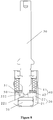
- the coil part includes a permanent magnet stepper motor 1, a three-stage gear reducer 2, and a threaded pair structure 5 for converting the rotational movement of the motor into the vertical movement of a screw rod 3.
- the valve body includes including a valve seat 10', and core components such as a corrugated pipe s 7 that controls a valve needle 8 to move up and down.
- an electronic controller of an air conditioning system controls an output shaft of the stepper motor 1 of the electronic expansion valve to rotate, the motor 1 cooperates with the gear reducer 2 to drive an output shaft of the gear reducer 2 to rotate, and the output shaft of the gear reducer 2 cooperates with the screw rod to drive the screw rod to rotate, then the screw rod cooperates with the thread substructure 5, to allow the screw rod to move up and down.
- a steel ball 11' is welded at a top end of the screw rod, a lower end of the steel ball 11' is provided with a liner 6, and a lower end of the liner 6 is connected to the valve needle 8.
- the above electronic expansion valve has a noise problem in actual operation. Specifically, in a case that an opening degree between the valve body and the valve port is small, due to the small opening degree of the valve port, obvious throttling will occur. The refrigerant passes through the valve port with a large flow velocity, causing a vortex with a specific frequency, resulting in abnormal noise, which affects the terminal user's comfort level.
- a main object of the present application is to provide an electronic expansion valve and a refrigeration system having the same, to address the problem of loud noise of the electronic expansion valve in the conventional art.
- the first sealing portion is made of a polymer material or a soft metallic material.
- valve needle includes a valve needle body and a valve seat core arranged in the valve needle body, the accommodation space is defined by an inner wall of the valve needle body and an upper surface of the valve seat core, and the second valve port and the second flow passage are arranged at the valve seat core.
- the first sealing portion is a first sealing ring
- the first sealing ring is clamped between the valve seat core and the first silencing portion
- the first sealing portion is provided with a first interference avoiding hole for avoiding the valve stem
- a peripheral side wall of the first sealing portion is fitted to the inner wall of the valve needle.
- the second flow passage is a first flow hole, there are multiple first flow holes, and the multiple first flow holes are arranged in a peripheral direction of the second valve port.
- the third flow passage is a second flow hole, there are multiple second flow holes, and the multiple second flow holes are arranged in one-to-one correspondence with the multiple first flow holes.
- the second flow holes are arc-shaped holes.
- the first silencing portion includes a first silencing structure and a second silencing structure, the first silencing structure is located above the second silencing structure, the first silencing structure blocks the first flow passage, and the second silencing structure blocks the third flow passage.
- the electronic expansion valve includes a second sealing portion, and the second sealing portion is arranged between the first silencing structure and the second silencing structure, to separate the first silencing structure and the second silencing structure.
- the second sealing portion is a second sealing ring
- the second sealing ring is provided with a second interference avoiding hole for avoiding the valve stem
- a peripheral side wall of the second sealing portion is fitted to the inner wall of the valve needle.
- the second sealing portion is made of a polymer material or a soft metallic material.
- both the first silencing structure and the second silencing structure are mesh-like silencing members, the first silencing structure and the second silencing structure are integrally formed, and a size of a mesh opening of the first silencing structure is different from a size of a mesh opening of the second silencing structure.
- the electronic expansion valve includes a second silencing portion, and the second silencing portion is arranged below the second valve port.
- a refrigeration system is provided according to another aspect of the present application, including the above electronic expansion valve.
- the electronic expansion valve includes a first sealing portion, the first sealing portion is arranged in the accommodation space and located between the first silencing portion and the second flow passage, the first sealing portion is provided with a third flow passage, and the accommodation space is in communication with the second flow passage through the third flow passage.
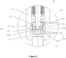
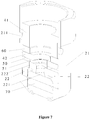
- valve body 11 first valve port, 20 valve needle, 21 valve needle body, 211 first flow passage, 22 valve seat core, 221 second valve port, 222 second flow passage, 223 flow guide groove, 23 accommodation space, 30 valve stem, 40 first silencing portion, 41 first silencing structure, 411 third interference avoiding hole, 42 second silencing structure, 421 fourth interference avoiding hole, 50 first sealing portion, 51 third flow passage, 52 first interference avoiding hole, 60 second sealing portion, 70 second silencing portion.
- an electronic expansion valve includes:
- the electronic expansion valve includes a first sealing portion 50, the first sealing portion 50 is arranged in the accommodation space 23 and located between the first silencing portion 40 and the second flow passage 222, the first sealing portion 50 is provided with a third flow passage 51, and the accommodation space 23 is in communication with the second flow passage 222 through the third flow passage 51.
- valve needle 20 When the valve stem 30 is driven to move downward by the driving portion, the valve needle 20 comes into contact with the stop member due to its own weight and a pressure differential force. The valve needle 20 is able to move synchronously with the valve stem 30 in this state due to the structure of the stop member until the valve needle 20 is at the closed position. When the valve needle 20 is at the closed position, the valve needle 20 starts to separate from the stop member, at this time, the valve stem 30 is able to move downward with respect to the valve needle 20. When the valve stem 30 abuts against the second valve port 221, the electronic expansion valve is in the small flow state.
- valve stem 30 When the valve stem 30 is driven to move upward by the driving portion, the valve stem 30 is able to move upward with respect to the valve needle 20 until the valve needle 20 comes into contact with the stop member. When the valve needle 20 is in contact with the stop member, the valve stem 30 starts to drive the valve needle 20 to move upward together. When the motor is started to reach a fully open pulse, the whole electronic expansion valve is in a fully open state. It should be noted that, as shown in Figure 5 , the valve stem 30 is able to move up and down within a travel range L1 by the driving of the driving portion.
- L1 is related to an opening degree of a section where the noise is generated.
- the first sealing portion 50 is made of a polymer material or a soft metallic material.
- the polymer material may be rubber or plastic
- the soft metal material may be various metallic materials having plasticity and low rigidity.
- the valve needle 20 includes a valve needle body 21 and a valve seat core 22 arranged in the valve needle body 21, the accommodation space 23 is defined by an inner wall of the valve needle body 21 and an upper surface of the valve seat core 22, and both the second valve port 221 and the second flow passage 222 are arranged at the valve seat core.
- the above structure is simple, and easy to manufacture and assemble.
- valve seat core 22 is further provided with a flow guide groove 223, and the flow guide groove 223 is arranged at a lower portion of the valve seat core 22 and is in communication with the second flow passage 222.
- the first sealing portion 50 is a first sealing ring
- the first sealing ring is clamped between the valve seat core 22 and the first silencing portion 40
- the first sealing ring is provided with a first interference avoiding hole 52 for avoiding the valve stem 30, and a peripheral side wall of the first sealing portion 50 is fitted to the inner wall of the valve needle 20.
- an outer diameter of the first sealing ring matches an inner diameter of the valve needle, and an upper surface of the first sealing ring may be embedded into the first silencing portion 40 having the uneven surface after being pressed.
- a lower surface of the first sealing ring abuts against the upper surface of the valve seat core 22.
- the first sealing ring is made of a polymer material or a soft metallic material
- the polymer material may be rubber, plastic, etc.
- the soft metallic material may be various metal materials having plasticity and low rigidity. Since the polymer material or the soft metallic material has advantages of low rigidity and high strength, the gap which may exist between the first silencing portion 40 and the valve seat core 22 can be effectively eliminated, thereby better improving the noise reduction effect and reducing the noise generated by the electronic expansion valve.
- the second flow passage 222 is embodied as a first flow hole, there are multiple first flow holes, and the multiple first flow holes are arranged in a peripheral direction of the second valve port 221.
- the third flow passage 51 is embodied as a second flow hole, there are multiple second flow holes, and the multiple second flow holes are arranged in one-to-one correspondence with the multiple first flow holes.
- the second flow holes are arc-shaped holes. Since the arc-shaped hole is long, with the above structure, it is easier for workers to align the second flow holes with the first flow holes during installation, which facilitates installation for the workers, and thereby improving working efficiency.
- the first silencing portion 40 includes a first silencing structure 41 and a second silencing structure 42, the first silencing structure 41 is located above the second silencing structure 42, the first silencing structure 41 blocks the first flow passage 211, and the second silencing structure 42 blocks the third flow passage 51.
- a utilization ratio of the first silencing portion 40 is improved, and thereby reducing the noise of the electronic expansion valve.
- the electronic expansion valve further includes a second sealing portion 60, the second sealing portion 60 is arranged between the first silencing structure 41 and the second silencing structure 42, to separate the first silencing structure 41 and the second silencing structure 42.
- the electronic expansion valve is in the small flow state.
- Another part of the fluid is blocked by the second sealing portion 60, so that it is repeatedly silenced in the first silencing structure 41 until it enters the accommodation space 23.
- the fluid which has flowed into the accommodation space 23 flows into the second silencing structure 42 for noise reduction, a part of the fluid flows out from the second flow passage 222 directly through the third flow passage 51.
- Another part of the fluid will be blocked by the first sealing portion 50 and flow into the first silencing portion 40 in a direction opposite to a previous flow direction for secondary noise reduction.
- This part of the fluid that is silenced flows into the third flow passage 51 and finally flows out from the second flow passage 222.
- the fluid When the fluid flows in from the second flow passage 222, the fluid will enter the second silencing structure 42 directly through the third flow passage 51 for noise reduction, after the fluid is silenced, a part of the fluid directly enters the fluid accommodation space 23.
- the fluid flowing into the accommodation space 23 continues to flow to the first silencing structure 41.
- Another part of the fluid is blocked by the second sealing portion 60, so that it is repeatedly silenced in the second silencing structure 42 until it flows into the accommodation space 23. All of the fluid that has flowed into the accommodation space 23 will flow into the first silencing portion 40 for secondary noise reduction.
- the above structure has the following two advantages.
- the first silencing portion 40 can be utilized repeatedly, which increases the utilization ratio, and improves the noise reduction effect.
- an effective distance through which the fluid is silenced is longer, which effectively prevents the fluid from flowing directly from the gap between the first silencing structure 41 and the second silencing structure 42.
- an annular area of the accommodation space 23 is much larger than an area of the first flow-through channel 211, so that the fluid can be silenced again after flowing into the accommodation space 23, which significantly improves the noise reduction effect.
- the above technical structure is relatively simple and has good manufacturability.
- the second sealing portion 60 is a second sealing ring, and the second sealing ring is provided with a second interference avoiding hole for avoiding the valve stem 30.
- a peripheral side wall of the second sealing portion 60 is fitted to the inner wall of the valve needle 20.
- the second sealing portion 60 is made of a polymer material or a soft metallic material.
- the polymer material may be rubber or plastic
- the soft metallic material may be various metallic materials having plasticity and low rigidity.
- an outer diameter of the second sealing ring matches the inner diameter of the valve needle 20.
- the electronic expansion valve further includes a second silencing portion 70, the second silencing portion 70 is arranged below the second valve port 221.
- the fluid flows from the first flow passage 211 to the second flow passage 222, it is first silenced by the first silencing portion 40, and then silenced again by the second silencing portion 70.
- the fluid flows from the second flow passage 222 to the first flow passage 211, it is first silenced by the second silencing portion 70, and then silenced again by the first silencing portion 40. Therefore, with the above structure, the fluid can be silenced twice, thereby significantly improving the noise reduction effect and reducing the noise of the electronic expansion valve.
- the first silencing structure 41 is in a cylindrical shape, and a middle portion of the first silencing structure 41 is provided with a third interference avoiding hole 411 for avoiding the valve stem 30.
- the second silencing structure 42 is in an annular shape, and a middle portion of the second silencing structure 42 is provided with a fourth interference avoiding hole 421 for avoiding the valve stem 30.
- both the first silencing structure 41 and the second silencing structure 42 are mesh-like silencing elements.
- the second silencing structure 42 is supported by a material such as a fine mesh plate which can be slightly compressed, and when the second silencing structure 42 is pressed, an uneven portion of the second silencing structure 42 may be inserted into the third flow passage 51.
- the electronic expansion valve according to a second embodiment differs from the first embodiment in the specific structure of the first silencing portion 40.
- both the first silencing structure 41 and the second silencing structure 42 are mesh-like silencing elements, and the first silencing structure 41 and the second silencing structure 42 are integrally formed, a size of a mesh opening of the first silencing structure 41 is different from a size of a mesh opening of the second silencing structure 42.
- the above structure makes the noise reduction effect better.
- the above structure may be arranged according to actual requirements of noise reduction and flow disturbance, for example, the mesh opening of the first silencing structure 41 may be arranged to be larger than the mesh opening of the second silencing structure 42.
- valve stem 30 When the valve needle 20 is at the closed position, the valve stem 30 abuts against the second valve port 221, and the fluid flows in from the first flow passage 211:
- valve stem 30 When the valve needle 20 is at the closed position, the valve stem 30 begins to move away from the second valve port 221, and the fluid flows in from the first flow passage 211:
- valve stem 30 When the valve needle 20 is at the closed position, the valve stem 30 abuts against the second valve port 221, and the fluid flows in from the second flow passage 222:
- valve stem 30 When the valve needle 20 is at the closed position, the valve stem 30 begins to move away from the second valve port 221, and the fluid flows in from the second flow passage 222:
- a refrigeration system is further provided according to the present application, an embodiment (not shown in Figures) of the refrigeration system according to the present application includes an electronic expansion valve, which is the electronic expansion valve described above. Since the above electronic expansion valve has an advantage of low noise, the refrigeration system having the electronic expansion valve has the above advantage.
Landscapes
- Engineering & Computer Science (AREA)
- General Engineering & Computer Science (AREA)
- Mechanical Engineering (AREA)
- Physics & Mathematics (AREA)
- Thermal Sciences (AREA)
- Details Of Valves (AREA)
- Lift Valve (AREA)
- Electrically Driven Valve-Operating Means (AREA)
Claims (14)
- Elektronisches Expansionsventil, umfassend:einen Ventilkörper (10) mit einer ersten Ventilöffnung (11) ;eine Ventilnadel (20), wobei die Ventilnadel (20) eine geschlossene Position aufweist, die an der ersten Ventilöffnung (11) anliegt, und eine offene Position, die von der ersten Ventilöffnung (11) entfernt ist, wobei ein Boden der Ventilnadel (20) mit einer zweiten Ventilöffnung (221) bereitgestellt ist, die mit der ersten Ventilöffnung (11) in Verbindung steht, wobei die Ventilnadel (20) mit einem Aufnahmeraum (23) und einem ersten Strömungsdurchgang (211) und einem zweiten Strömungsdurchgang (222) bereitgestellt ist, die beide mit dem Aufnahmeraum (23) in Verbindung stehen, wobei der erste Strömungsdurchgang (211) in einer Seitenwand der Ventilnadel (20) angeordnet ist und mit einer Außenseite in Verbindung steht, und der zweite Strömungsdurchgang (222) an einer äußeren Umfangsseite der zweiten Ventilöffnung (221) angeordnet ist und mit der zweiten Ventilöffnung (221) in Verbindung steht;einen Ventilschaft (30), wobei der Ventilschaft (30) dazu angeordnet ist, dass zumindest ein Teil des Ventilschaftes (30) in den Aufnahmeraum (23) eindringen kann, und der Ventilschaft (30) zum Einstellen einer Durchflussrate an der zweiten Ventilöffnung (221) nach oben und unten bewegbar ist;einen ersten Schalldämpfungsabschnitt (40), wobei der erste Schalldämpfungsabschnitt (40) im Aufnahmeraum (23) dazu angeordnet ist, zu ermöglichen, dass ein Fluid, das vom ersten Strömungsdurchgang (211) eintritt, durch den ersten Schalldämpfungsabschnitt (40) hindurchgeht und zum zweiten Strömungsdurchgang (222) strömt;einen ersten Dichtungsabschnitt (50), wobei der erste Dichtungsabschnitt (50) im Aufnahmeraum (23) angeordnet ist und sich zwischen dem ersten Schalldämpfungsabschnitt (40) und dem zweiten Strömungsdurchgang (222) befindet, der erste Dichtungsabschnitt (50) mit einem dritten Strömungsdurchgang (51) bereitgestellt ist und der Aufnahmeraum (23) durch den dritten Strömungsdurchgang (51) mit dem zweiten Strömungsdurchgang (222) in Verbindung steht; undeinen Antriebsabschnitt, der dafür ausgelegt ist, den Ventilschaft (30) zur Auf- und Abwärtsbewegung anzutreiben; undwobei ein Anschlagelement zwischen dem Ventilschaft (30) und der Ventilnadel (20) dazu bereitgestellt ist, es der Ventilnadel (20) und dem Ventilschaft (30) zu ermöglichen, sich synchron zu bewegen, wenn die Ventilnadel (20) durch das Anschlagelement in Kontakt mit dem Ventilschaft (30) ist; und das Anschlagelement außerdem dafür ausgelegt ist, dem Ventilschaft (30) zu ermöglichen, sich in Bezug auf die Ventilnadel (20) nach oben und unten zu bewegen, wenn sich die Ventilnadel (20) in der geschlossenen Position befindet.
- Elektronisches Expansionsventil nach Anspruch 1, wobei der erste Dichtungsabschnitt (50) aus einem Polymermaterial oder einem weichen metallischen Material hergestellt ist.
- Elektronisches Expansionsventil nach Anspruch 1, wobei die Ventilnadel (20) einen Ventilnadelkörper (21) und einen im Ventilnadelkörper (21) angeordneten Ventilsitzkern (22) umfasst, der Aufnahmeraum (23) durch eine Innenwand des Ventilnadelkörpers (21) und eine obere Fläche des Ventilsitzkerns (22) definiert ist, und die zweite Ventilöffnung (221) und der zweite Strömungsdurchgang (222) am Ventilsitzkern (22) angeordnet sind.
- Elektronisches Expansionsventil nach Anspruch 3, wobei der erste Dichtungsabschnitt (50) ein erster Dichtungsring ist, der erste Dichtungsring zwischen dem Ventilsitzkern (22) und dem ersten Schalldämpfungsabschnitt (40) eingeklemmt ist, der erste Dichtungsabschnitt mit einem ersten Eingriffsvermeidungsloch (52) zum Vermeiden des Ventilschafts (30) bereitgestellt ist und eine Umfangsseitenwand des ersten Dichtungsabschnitts (50) an die Innenwand der Ventilnadel (20) angepasst ist.
- Elektronisches Expansionsventil nach Anspruch 1, wobei der zweite Strömungsdurchgang (222) als ein erstes Strömungsloch ausgeführt ist, eine Vielzahl von ersten Strömungslöchern vorhanden ist und die Vielzahl von ersten Strömungslöchern in einer Umfangsrichtung der zweiten Ventilöffnung (221) angeordnet sind.
- Elektronisches Expansionsventil nach Anspruch 5, wobei der dritte Strömungsdurchgang (51) als ein zweites Strömungsloch ausgeführt ist, eine Vielzahl von zweiten Strömungslöchern vorhanden ist und die Vielzahl von zweiten Strömungslöchern in Eins-zu-eins-Entsprechung mit der Vielzahl der ersten Strömungslöcher angeordnet sind.
- Elektronisches Expansionsventil nach Anspruch 6, wobei die zweiten Strömungslöcher bogenförmige Löcher sind.
- Elektronisches Expansionsventil nach Anspruch 1, wobei der erste Schalldämpfungsabschnitt (40) eine erste Schalldämpfungsstruktur (41) und eine zweite Schalldämpfungsstruktur (42) umfasst, die erste Schalldämpfungsstruktur (41) über der zweiten Schalldämpfungsstruktur (42) angeordnet ist, die erste Schalldämpfungsstruktur (41) dafür ausgelegt ist, den ersten Strömungsdurchgang (211) zu blockieren, und die zweite Schalldämpfungsstruktur (42) dafür ausgelegt ist, den dritten Strömungsdurchgang (51) zu blockieren.
- Elektronisches Expansionsventil nach Anspruch 8, ferner umfassend einen zweiten Dichtungsabschnitt (60), wobei der zweite Dichtungsabschnitt (60) zwischen der ersten Schalldämpfungsstruktur (41) und der zweiten Schalldämpfungsstruktur (42) angeordnet ist, zu dem Zweck, die erste Schalldämpfungsstruktur (41) von der zweiten Schalldämpfungsstruktur (42) zu trennen.
- Elektronisches Expansionsventil nach Anspruch 9, wobei der zweite Dichtungsabschnitt (60) ein zweiter Dichtungsring ist, der zweite Dichtungsring mit einem zweiten Eingriffsvermeidungsloch zum Vermeiden des Ventilschafts (30) bereitgestellt ist, und eine Umfangsseitenwand des zweiten Dichtungsabschnitts (60) an die Innenwand der Ventilnadel (20) angepasst ist.
- Elektronisches Expansionsventil nach Anspruch 9, wobei der zweite Dichtungsabschnitt (60) aus einem Polymermaterial oder einem weichen metallischen Material hergestellt ist.
- Elektronisches Expansionsventil nach Anspruch 8, wobei sowohl die erste Schalldämpfungsstruktur (41) als auch die zweite Schalldämpfungsstruktur (42) maschenartige Schalldämpfungselemente sind, die erste Schalldämpfungsstruktur (41) und die zweite Schalldämpfungsstruktur (42) einstückig ausgebildet sind und eine Größe einer Maschenöffnung der ersten Schalldämpfungsstruktur (41) sich von einer Größe einer Maschenöffnung der zweiten Schalldämpfungsstruktur (42) unterscheidet.
- Elektronisches Expansionsventil nach Anspruch 1, ferner umfassend einen zweiten Schalldämpfungsabschnitt (70), der unterhalb der zweiten Ventilöffnung (221) angeordnet ist.
- Kühlsystem, umfassend ein elektronisches Expansionsventil, wobei das elektronische Expansionsventil das elektronische Expansionsventil nach einem der Ansprüche 1 bis 13 ist.
Applications Claiming Priority (2)
| Application Number | Priority Date | Filing Date | Title |
|---|---|---|---|
| CN201611085736.9A CN108119698B (zh) | 2016-11-30 | 2016-11-30 | 电子膨胀阀及具有其的制冷系统 |
| PCT/CN2017/113893 WO2018099422A1 (zh) | 2016-11-30 | 2017-11-30 | 电子膨胀阀及具有其的制冷系统 |
Publications (3)
| Publication Number | Publication Date |
|---|---|
| EP3550193A1 EP3550193A1 (de) | 2019-10-09 |
| EP3550193A4 EP3550193A4 (de) | 2020-08-05 |
| EP3550193B1 true EP3550193B1 (de) | 2021-08-25 |
Family
ID=62227426
Family Applications (1)
| Application Number | Title | Priority Date | Filing Date |
|---|---|---|---|
| EP17875890.0A Active EP3550193B1 (de) | 2016-11-30 | 2017-11-30 | Elektronisches expansionsventil und kühlsystem damit |
Country Status (5)
| Country | Link |
|---|---|
| EP (1) | EP3550193B1 (de) |
| JP (1) | JP6757472B2 (de) |
| KR (1) | KR102191738B1 (de) |
| CN (1) | CN108119698B (de) |
| WO (1) | WO2018099422A1 (de) |
Families Citing this family (8)
| Publication number | Priority date | Publication date | Assignee | Title |
|---|---|---|---|---|
| JP6966416B2 (ja) * | 2018-12-27 | 2021-11-17 | 株式会社鷺宮製作所 | 弁装置および冷凍サイクルシステム |
| CN109654233B (zh) * | 2019-01-25 | 2024-01-16 | 浙江科博电器有限公司 | 具有防水垢和消音功能的废水阀 |
| KR102447040B1 (ko) * | 2019-10-02 | 2022-09-26 | 동일기계공업 주식회사 | 전자식 팽창 및 방향전환 일체화 밸브 |
| PL4078051T3 (pl) * | 2019-12-20 | 2024-03-04 | Danfoss A/S | Zawór rozprężny |
| CN113324045B (zh) * | 2020-02-28 | 2026-02-24 | 浙江三花智能控制股份有限公司 | 电子膨胀阀 |
| CN114135714B (zh) * | 2020-09-03 | 2024-04-02 | 浙江盾安人工环境股份有限公司 | 节流阀 |
| CN114811058B (zh) * | 2021-12-31 | 2025-05-23 | 北京爱生科技发展有限公司 | 一种养殖容器自净化排污阀 |
| CN119665492A (zh) * | 2023-04-24 | 2025-03-21 | 浙江三花智能控制股份有限公司 | 电子膨胀阀 |
Family Cites Families (16)
| Publication number | Priority date | Publication date | Assignee | Title |
|---|---|---|---|---|
| JP3164480B2 (ja) * | 1994-11-11 | 2001-05-08 | 太平洋工業株式会社 | 電動膨張弁の構造 |
| JP4071451B2 (ja) * | 2001-04-12 | 2008-04-02 | 株式会社鷺宮製作所 | 絞り装置および空気調和機 |
| JP4103363B2 (ja) * | 2001-09-18 | 2008-06-18 | 三菱電機株式会社 | 流量制御装置、冷凍サイクル装置および空気調和装置 |
| JP4077340B2 (ja) * | 2003-02-06 | 2008-04-16 | 株式会社鷺宮製作所 | 絞り弁装置および空気調和機 |
| JP2005331153A (ja) * | 2004-05-19 | 2005-12-02 | Saginomiya Seisakusho Inc | 絞り弁装置および空気調和機 |
| JP2012117584A (ja) * | 2010-11-30 | 2012-06-21 | Saginomiya Seisakusho Inc | 電動流量制御弁 |
| CN201934686U (zh) * | 2010-12-07 | 2011-08-17 | 居琴 | 电子膨胀阀的阀座连接结构 |
| CN102644785B (zh) * | 2011-02-17 | 2014-04-30 | 浙江三花股份有限公司 | 一种电子膨胀阀 |
| CN102901279B (zh) * | 2011-07-27 | 2015-07-22 | 浙江三花股份有限公司 | 一种电子膨胀阀 |
| WO2013170542A1 (zh) * | 2012-05-18 | 2013-11-21 | 浙江三花股份有限公司 | 一种电子膨胀阀 |
| CN103511636B (zh) * | 2012-06-27 | 2016-04-06 | 浙江三花股份有限公司 | 一种电子膨胀阀 |
| CN202971946U (zh) * | 2012-12-07 | 2013-06-05 | 艾默生环境优化技术(苏州)有限公司 | 电子膨胀阀 |
| JP6142181B2 (ja) * | 2013-03-12 | 2017-06-07 | 株式会社テージーケー | 膨張弁および防振ばね |
| CN105626876A (zh) * | 2014-10-28 | 2016-06-01 | 浙江盾安人工环境股份有限公司 | 电子膨胀阀 |
| CN105650337A (zh) * | 2014-11-13 | 2016-06-08 | 浙江三花股份有限公司 | 电子膨胀阀 |
| CN205534555U (zh) * | 2016-01-26 | 2016-08-31 | 浙江三花股份有限公司 | 一种电子膨胀阀 |
-
2016
- 2016-11-30 CN CN201611085736.9A patent/CN108119698B/zh active Active
-
2017
- 2017-11-30 JP JP2019528843A patent/JP6757472B2/ja active Active
- 2017-11-30 KR KR1020197017856A patent/KR102191738B1/ko active Active
- 2017-11-30 WO PCT/CN2017/113893 patent/WO2018099422A1/zh not_active Ceased
- 2017-11-30 EP EP17875890.0A patent/EP3550193B1/de active Active
Also Published As
| Publication number | Publication date |
|---|---|
| KR20190087527A (ko) | 2019-07-24 |
| CN108119698B (zh) | 2021-11-02 |
| CN108119698A (zh) | 2018-06-05 |
| EP3550193A1 (de) | 2019-10-09 |
| EP3550193A4 (de) | 2020-08-05 |
| JP6757472B2 (ja) | 2020-09-16 |
| KR102191738B1 (ko) | 2020-12-17 |
| JP2020513512A (ja) | 2020-05-14 |
| WO2018099422A1 (zh) | 2018-06-07 |
Similar Documents
| Publication | Publication Date | Title |
|---|---|---|
| EP3550193B1 (de) | Elektronisches expansionsventil und kühlsystem damit | |
| JP2021516319A (ja) | 電子膨張弁 | |
| JP5696093B2 (ja) | 電動弁 | |
| EP2924373B1 (de) | Elektrisch betätigtes ventil | |
| CN107356025B (zh) | 电子膨胀阀 | |
| JP4570473B2 (ja) | 弁装置および冷凍サイクル装置 | |
| CN107435754A (zh) | 流量调节阀 | |
| JP4285155B2 (ja) | 多段電動膨張弁及び冷凍装置 | |
| WO2017097232A1 (zh) | 二段式电子膨胀阀 | |
| CN106168304B (zh) | 电动阀 | |
| JP2014081046A (ja) | 流量制御弁 | |
| CN106895153A (zh) | 二段式电子膨胀阀 | |
| JP6850364B2 (ja) | 電子膨張弁及それを具備する冷凍システム | |
| KR20120020046A (ko) | 팽창 밸브 | |
| CN107044543A (zh) | 二段式电子膨胀阀 | |
| CN104048067A (zh) | 燃气灶及其燃气流量控制装置 | |
| JP2011133139A (ja) | 膨張弁 | |
| CN109425150A (zh) | 电子膨胀阀及具有其的制冷系统 | |
| CN109425151B (zh) | 电子膨胀阀及具有其的制冷系统 | |
| CN107965952A (zh) | 电子膨胀阀以及具有其的制冷系统 | |
| KR102138432B1 (ko) | 전기 밸브 | |
| CN110939781A (zh) | 一种双向节流阀 | |
| WO2019146345A1 (ja) | 流量調整弁 | |
| CN102818068A (zh) | 一种阀体部件和使用该阀体部件的电子膨胀阀 | |
| CN108119697A (zh) | 电子膨胀阀及具有其的制冷系统 |
Legal Events
| Date | Code | Title | Description |
|---|---|---|---|
| STAA | Information on the status of an ep patent application or granted ep patent |
Free format text: STATUS: THE INTERNATIONAL PUBLICATION HAS BEEN MADE |
|
| PUAI | Public reference made under article 153(3) epc to a published international application that has entered the european phase |
Free format text: ORIGINAL CODE: 0009012 |
|
| STAA | Information on the status of an ep patent application or granted ep patent |
Free format text: STATUS: REQUEST FOR EXAMINATION WAS MADE |
|
| 17P | Request for examination filed |
Effective date: 20190618 |
|
| AK | Designated contracting states |
Kind code of ref document: A1 Designated state(s): AL AT BE BG CH CY CZ DE DK EE ES FI FR GB GR HR HU IE IS IT LI LT LU LV MC MK MT NL NO PL PT RO RS SE SI SK SM TR |
|
| AX | Request for extension of the european patent |
Extension state: BA ME |
|
| DAV | Request for validation of the european patent (deleted) | ||
| DAX | Request for extension of the european patent (deleted) | ||
| A4 | Supplementary search report drawn up and despatched |
Effective date: 20200706 |
|
| RIC1 | Information provided on ipc code assigned before grant |
Ipc: F16K 47/02 20060101AFI20200630BHEP Ipc: F16K 1/00 20060101ALI20200630BHEP Ipc: F25B 41/06 20060101ALI20200630BHEP |
|
| REG | Reference to a national code |
Ref country code: DE Ref legal event code: R079 Ref document number: 602017044937 Country of ref document: DE Free format text: PREVIOUS MAIN CLASS: F16K0047020000 Ipc: F25B0041300000 |
|
| RIC1 | Information provided on ipc code assigned before grant |
Ipc: F16K 47/02 20060101ALI20210208BHEP Ipc: F25B 41/31 20210101ALI20210208BHEP Ipc: F25B 41/35 20210101ALI20210208BHEP Ipc: F16K 1/00 20060101ALI20210208BHEP Ipc: F25B 41/30 20210101AFI20210208BHEP |
|
| GRAP | Despatch of communication of intention to grant a patent |
Free format text: ORIGINAL CODE: EPIDOSNIGR1 |
|
| STAA | Information on the status of an ep patent application or granted ep patent |
Free format text: STATUS: GRANT OF PATENT IS INTENDED |
|
| INTG | Intention to grant announced |
Effective date: 20210319 |
|
| GRAS | Grant fee paid |
Free format text: ORIGINAL CODE: EPIDOSNIGR3 |
|
| GRAA | (expected) grant |
Free format text: ORIGINAL CODE: 0009210 |
|
| STAA | Information on the status of an ep patent application or granted ep patent |
Free format text: STATUS: THE PATENT HAS BEEN GRANTED |
|
| AK | Designated contracting states |
Kind code of ref document: B1 Designated state(s): AL AT BE BG CH CY CZ DE DK EE ES FI FR GB GR HR HU IE IS IT LI LT LU LV MC MK MT NL NO PL PT RO RS SE SI SK SM TR |
|
| REG | Reference to a national code |
Ref country code: CH Ref legal event code: EP |
|
| REG | Reference to a national code |
Ref country code: IE Ref legal event code: FG4D Ref country code: AT Ref legal event code: REF Ref document number: 1424200 Country of ref document: AT Kind code of ref document: T Effective date: 20210915 |
|
| REG | Reference to a national code |
Ref country code: DE Ref legal event code: R096 Ref document number: 602017044937 Country of ref document: DE |
|
| REG | Reference to a national code |
Ref country code: LT Ref legal event code: MG9D |
|
| REG | Reference to a national code |
Ref country code: NL Ref legal event code: MP Effective date: 20210825 |
|
| REG | Reference to a national code |
Ref country code: AT Ref legal event code: MK05 Ref document number: 1424200 Country of ref document: AT Kind code of ref document: T Effective date: 20210825 |
|
| PG25 | Lapsed in a contracting state [announced via postgrant information from national office to epo] |
Ref country code: LT Free format text: LAPSE BECAUSE OF FAILURE TO SUBMIT A TRANSLATION OF THE DESCRIPTION OR TO PAY THE FEE WITHIN THE PRESCRIBED TIME-LIMIT Effective date: 20210825 Ref country code: AT Free format text: LAPSE BECAUSE OF FAILURE TO SUBMIT A TRANSLATION OF THE DESCRIPTION OR TO PAY THE FEE WITHIN THE PRESCRIBED TIME-LIMIT Effective date: 20210825 Ref country code: BG Free format text: LAPSE BECAUSE OF FAILURE TO SUBMIT A TRANSLATION OF THE DESCRIPTION OR TO PAY THE FEE WITHIN THE PRESCRIBED TIME-LIMIT Effective date: 20211125 Ref country code: PT Free format text: LAPSE BECAUSE OF FAILURE TO SUBMIT A TRANSLATION OF THE DESCRIPTION OR TO PAY THE FEE WITHIN THE PRESCRIBED TIME-LIMIT Effective date: 20211227 Ref country code: NO Free format text: LAPSE BECAUSE OF FAILURE TO SUBMIT A TRANSLATION OF THE DESCRIPTION OR TO PAY THE FEE WITHIN THE PRESCRIBED TIME-LIMIT Effective date: 20211125 Ref country code: RS Free format text: LAPSE BECAUSE OF FAILURE TO SUBMIT A TRANSLATION OF THE DESCRIPTION OR TO PAY THE FEE WITHIN THE PRESCRIBED TIME-LIMIT Effective date: 20210825 Ref country code: SE Free format text: LAPSE BECAUSE OF FAILURE TO SUBMIT A TRANSLATION OF THE DESCRIPTION OR TO PAY THE FEE WITHIN THE PRESCRIBED TIME-LIMIT Effective date: 20210825 Ref country code: HR Free format text: LAPSE BECAUSE OF FAILURE TO SUBMIT A TRANSLATION OF THE DESCRIPTION OR TO PAY THE FEE WITHIN THE PRESCRIBED TIME-LIMIT Effective date: 20210825 Ref country code: FI Free format text: LAPSE BECAUSE OF FAILURE TO SUBMIT A TRANSLATION OF THE DESCRIPTION OR TO PAY THE FEE WITHIN THE PRESCRIBED TIME-LIMIT Effective date: 20210825 Ref country code: ES Free format text: LAPSE BECAUSE OF FAILURE TO SUBMIT A TRANSLATION OF THE DESCRIPTION OR TO PAY THE FEE WITHIN THE PRESCRIBED TIME-LIMIT Effective date: 20210825 |
|
| PG25 | Lapsed in a contracting state [announced via postgrant information from national office to epo] |
Ref country code: PL Free format text: LAPSE BECAUSE OF FAILURE TO SUBMIT A TRANSLATION OF THE DESCRIPTION OR TO PAY THE FEE WITHIN THE PRESCRIBED TIME-LIMIT Effective date: 20210825 Ref country code: LV Free format text: LAPSE BECAUSE OF FAILURE TO SUBMIT A TRANSLATION OF THE DESCRIPTION OR TO PAY THE FEE WITHIN THE PRESCRIBED TIME-LIMIT Effective date: 20210825 Ref country code: GR Free format text: LAPSE BECAUSE OF FAILURE TO SUBMIT A TRANSLATION OF THE DESCRIPTION OR TO PAY THE FEE WITHIN THE PRESCRIBED TIME-LIMIT Effective date: 20211126 |
|
| PG25 | Lapsed in a contracting state [announced via postgrant information from national office to epo] |
Ref country code: NL Free format text: LAPSE BECAUSE OF FAILURE TO SUBMIT A TRANSLATION OF THE DESCRIPTION OR TO PAY THE FEE WITHIN THE PRESCRIBED TIME-LIMIT Effective date: 20210825 |
|
| PG25 | Lapsed in a contracting state [announced via postgrant information from national office to epo] |
Ref country code: DK Free format text: LAPSE BECAUSE OF FAILURE TO SUBMIT A TRANSLATION OF THE DESCRIPTION OR TO PAY THE FEE WITHIN THE PRESCRIBED TIME-LIMIT Effective date: 20210825 |
|
| REG | Reference to a national code |
Ref country code: DE Ref legal event code: R097 Ref document number: 602017044937 Country of ref document: DE |
|
| PG25 | Lapsed in a contracting state [announced via postgrant information from national office to epo] |
Ref country code: SM Free format text: LAPSE BECAUSE OF FAILURE TO SUBMIT A TRANSLATION OF THE DESCRIPTION OR TO PAY THE FEE WITHIN THE PRESCRIBED TIME-LIMIT Effective date: 20210825 Ref country code: SK Free format text: LAPSE BECAUSE OF FAILURE TO SUBMIT A TRANSLATION OF THE DESCRIPTION OR TO PAY THE FEE WITHIN THE PRESCRIBED TIME-LIMIT Effective date: 20210825 Ref country code: RO Free format text: LAPSE BECAUSE OF FAILURE TO SUBMIT A TRANSLATION OF THE DESCRIPTION OR TO PAY THE FEE WITHIN THE PRESCRIBED TIME-LIMIT Effective date: 20210825 Ref country code: EE Free format text: LAPSE BECAUSE OF FAILURE TO SUBMIT A TRANSLATION OF THE DESCRIPTION OR TO PAY THE FEE WITHIN THE PRESCRIBED TIME-LIMIT Effective date: 20210825 Ref country code: CZ Free format text: LAPSE BECAUSE OF FAILURE TO SUBMIT A TRANSLATION OF THE DESCRIPTION OR TO PAY THE FEE WITHIN THE PRESCRIBED TIME-LIMIT Effective date: 20210825 Ref country code: AL Free format text: LAPSE BECAUSE OF FAILURE TO SUBMIT A TRANSLATION OF THE DESCRIPTION OR TO PAY THE FEE WITHIN THE PRESCRIBED TIME-LIMIT Effective date: 20210825 |
|
| PG25 | Lapsed in a contracting state [announced via postgrant information from national office to epo] |
Ref country code: MC Free format text: LAPSE BECAUSE OF FAILURE TO SUBMIT A TRANSLATION OF THE DESCRIPTION OR TO PAY THE FEE WITHIN THE PRESCRIBED TIME-LIMIT Effective date: 20210825 |
|
| REG | Reference to a national code |
Ref country code: CH Ref legal event code: PL |
|
| PLBE | No opposition filed within time limit |
Free format text: ORIGINAL CODE: 0009261 |
|
| STAA | Information on the status of an ep patent application or granted ep patent |
Free format text: STATUS: NO OPPOSITION FILED WITHIN TIME LIMIT |
|
| PG25 | Lapsed in a contracting state [announced via postgrant information from national office to epo] |
Ref country code: LU Free format text: LAPSE BECAUSE OF NON-PAYMENT OF DUE FEES Effective date: 20211130 Ref country code: IT Free format text: LAPSE BECAUSE OF FAILURE TO SUBMIT A TRANSLATION OF THE DESCRIPTION OR TO PAY THE FEE WITHIN THE PRESCRIBED TIME-LIMIT Effective date: 20210825 |
|
| 26N | No opposition filed |
Effective date: 20220527 |
|
| PG25 | Lapsed in a contracting state [announced via postgrant information from national office to epo] |
Ref country code: SI Free format text: LAPSE BECAUSE OF FAILURE TO SUBMIT A TRANSLATION OF THE DESCRIPTION OR TO PAY THE FEE WITHIN THE PRESCRIBED TIME-LIMIT Effective date: 20210825 Ref country code: LI Free format text: LAPSE BECAUSE OF NON-PAYMENT OF DUE FEES Effective date: 20211130 Ref country code: CH Free format text: LAPSE BECAUSE OF NON-PAYMENT OF DUE FEES Effective date: 20211130 |
|
| PG25 | Lapsed in a contracting state [announced via postgrant information from national office to epo] |
Ref country code: IE Free format text: LAPSE BECAUSE OF NON-PAYMENT OF DUE FEES Effective date: 20211130 |
|
| PG25 | Lapsed in a contracting state [announced via postgrant information from national office to epo] |
Ref country code: CY Free format text: LAPSE BECAUSE OF FAILURE TO SUBMIT A TRANSLATION OF THE DESCRIPTION OR TO PAY THE FEE WITHIN THE PRESCRIBED TIME-LIMIT Effective date: 20210825 |
|
| P01 | Opt-out of the competence of the unified patent court (upc) registered |
Effective date: 20230530 |
|
| PG25 | Lapsed in a contracting state [announced via postgrant information from national office to epo] |
Ref country code: HU Free format text: LAPSE BECAUSE OF FAILURE TO SUBMIT A TRANSLATION OF THE DESCRIPTION OR TO PAY THE FEE WITHIN THE PRESCRIBED TIME-LIMIT; INVALID AB INITIO Effective date: 20171130 |
|
| PG25 | Lapsed in a contracting state [announced via postgrant information from national office to epo] |
Ref country code: MK Free format text: LAPSE BECAUSE OF FAILURE TO SUBMIT A TRANSLATION OF THE DESCRIPTION OR TO PAY THE FEE WITHIN THE PRESCRIBED TIME-LIMIT Effective date: 20210825 |
|
| PG25 | Lapsed in a contracting state [announced via postgrant information from national office to epo] |
Ref country code: MT Free format text: LAPSE BECAUSE OF FAILURE TO SUBMIT A TRANSLATION OF THE DESCRIPTION OR TO PAY THE FEE WITHIN THE PRESCRIBED TIME-LIMIT Effective date: 20210825 |
|
| PG25 | Lapsed in a contracting state [announced via postgrant information from national office to epo] |
Ref country code: TR Free format text: LAPSE BECAUSE OF FAILURE TO SUBMIT A TRANSLATION OF THE DESCRIPTION OR TO PAY THE FEE WITHIN THE PRESCRIBED TIME-LIMIT Effective date: 20210825 |
|
| PGFP | Annual fee paid to national office [announced via postgrant information from national office to epo] |
Ref country code: DE Payment date: 20251117 Year of fee payment: 9 |
|
| PGFP | Annual fee paid to national office [announced via postgrant information from national office to epo] |
Ref country code: GB Payment date: 20251126 Year of fee payment: 9 |
|
| PGFP | Annual fee paid to national office [announced via postgrant information from national office to epo] |
Ref country code: FR Payment date: 20251128 Year of fee payment: 9 |
|
| PGFP | Annual fee paid to national office [announced via postgrant information from national office to epo] |
Ref country code: BE Payment date: 20251120 Year of fee payment: 9 |