EP3550193B1 - Electronic expansion valve and refrigeration system having same - Google Patents
Electronic expansion valve and refrigeration system having same Download PDFInfo
- Publication number
- EP3550193B1 EP3550193B1 EP17875890.0A EP17875890A EP3550193B1 EP 3550193 B1 EP3550193 B1 EP 3550193B1 EP 17875890 A EP17875890 A EP 17875890A EP 3550193 B1 EP3550193 B1 EP 3550193B1
- Authority
- EP
- European Patent Office
- Prior art keywords
- valve
- silencing
- flow passage
- electronic expansion
- flow
- Prior art date
- Legal status (The legal status is an assumption and is not a legal conclusion. Google has not performed a legal analysis and makes no representation as to the accuracy of the status listed.)
- Active
Links
Images


Classifications
-
- F—MECHANICAL ENGINEERING; LIGHTING; HEATING; WEAPONS; BLASTING
- F16—ENGINEERING ELEMENTS AND UNITS; GENERAL MEASURES FOR PRODUCING AND MAINTAINING EFFECTIVE FUNCTIONING OF MACHINES OR INSTALLATIONS; THERMAL INSULATION IN GENERAL
- F16K—VALVES; TAPS; COCKS; ACTUATING-FLOATS; DEVICES FOR VENTING OR AERATING
- F16K47/00—Means in valves for absorbing fluid energy
- F16K47/02—Means in valves for absorbing fluid energy for preventing water-hammer or noise
-
- F—MECHANICAL ENGINEERING; LIGHTING; HEATING; WEAPONS; BLASTING
- F25—REFRIGERATION OR COOLING; COMBINED HEATING AND REFRIGERATION SYSTEMS; HEAT PUMP SYSTEMS; MANUFACTURE OR STORAGE OF ICE; LIQUEFACTION SOLIDIFICATION OF GASES
- F25B—REFRIGERATION MACHINES, PLANTS OR SYSTEMS; COMBINED HEATING AND REFRIGERATION SYSTEMS; HEAT PUMP SYSTEMS
- F25B41/00—Fluid-circulation arrangements
- F25B41/30—Expansion means; Dispositions thereof
- F25B41/31—Expansion valves
- F25B41/34—Expansion valves with the valve member being actuated by electric means, e.g. by piezoelectric actuators
- F25B41/35—Expansion valves with the valve member being actuated by electric means, e.g. by piezoelectric actuators by rotary motors, e.g. by stepping motors
-
- F—MECHANICAL ENGINEERING; LIGHTING; HEATING; WEAPONS; BLASTING
- F16—ENGINEERING ELEMENTS AND UNITS; GENERAL MEASURES FOR PRODUCING AND MAINTAINING EFFECTIVE FUNCTIONING OF MACHINES OR INSTALLATIONS; THERMAL INSULATION IN GENERAL
- F16K—VALVES; TAPS; COCKS; ACTUATING-FLOATS; DEVICES FOR VENTING OR AERATING
- F16K1/00—Lift valves or globe valves, i.e. cut-off apparatus with closure members having at least a component of their opening and closing motion perpendicular to the closing faces
-
- F—MECHANICAL ENGINEERING; LIGHTING; HEATING; WEAPONS; BLASTING
- F25—REFRIGERATION OR COOLING; COMBINED HEATING AND REFRIGERATION SYSTEMS; HEAT PUMP SYSTEMS; MANUFACTURE OR STORAGE OF ICE; LIQUEFACTION SOLIDIFICATION OF GASES
- F25B—REFRIGERATION MACHINES, PLANTS OR SYSTEMS; COMBINED HEATING AND REFRIGERATION SYSTEMS; HEAT PUMP SYSTEMS
- F25B41/00—Fluid-circulation arrangements
- F25B41/30—Expansion means; Dispositions thereof
- F25B41/31—Expansion valves
- F25B41/34—Expansion valves with the valve member being actuated by electric means, e.g. by piezoelectric actuators
-
- F—MECHANICAL ENGINEERING; LIGHTING; HEATING; WEAPONS; BLASTING
- F25—REFRIGERATION OR COOLING; COMBINED HEATING AND REFRIGERATION SYSTEMS; HEAT PUMP SYSTEMS; MANUFACTURE OR STORAGE OF ICE; LIQUEFACTION SOLIDIFICATION OF GASES
- F25B—REFRIGERATION MACHINES, PLANTS OR SYSTEMS; COMBINED HEATING AND REFRIGERATION SYSTEMS; HEAT PUMP SYSTEMS
- F25B2500/00—Problems to be solved
- F25B2500/12—Sound
-
- Y—GENERAL TAGGING OF NEW TECHNOLOGICAL DEVELOPMENTS; GENERAL TAGGING OF CROSS-SECTIONAL TECHNOLOGIES SPANNING OVER SEVERAL SECTIONS OF THE IPC; TECHNICAL SUBJECTS COVERED BY FORMER USPC CROSS-REFERENCE ART COLLECTIONS [XRACs] AND DIGESTS
- Y02—TECHNOLOGIES OR APPLICATIONS FOR MITIGATION OR ADAPTATION AGAINST CLIMATE CHANGE
- Y02B—CLIMATE CHANGE MITIGATION TECHNOLOGIES RELATED TO BUILDINGS, e.g. HOUSING, HOUSE APPLIANCES OR RELATED END-USER APPLICATIONS
- Y02B30/00—Energy efficient heating, ventilation or air conditioning [HVAC]
- Y02B30/70—Efficient control or regulation technologies, e.g. for control of refrigerant flow, motor or heating
Definitions
- the present application relates to the technical field of refrigeration, and in particular to an electronic expansion valve and a refrigeration system having the same.
- a deceleration type electronic expansion valve used in an inverter air conditioner is mainly composed of two parts, one part is a valve body part for flow regulation, and the other part is a coil part for driving.
- the coil part includes a permanent magnet stepper motor 1, a three-stage gear reducer 2, and a threaded pair structure 5 for converting the rotational movement of the motor into the vertical movement of a screw rod 3.
- the valve body includes including a valve seat 10', and core components such as a corrugated pipe s 7 that controls a valve needle 8 to move up and down.
- an electronic controller of an air conditioning system controls an output shaft of the stepper motor 1 of the electronic expansion valve to rotate, the motor 1 cooperates with the gear reducer 2 to drive an output shaft of the gear reducer 2 to rotate, and the output shaft of the gear reducer 2 cooperates with the screw rod to drive the screw rod to rotate, then the screw rod cooperates with the thread substructure 5, to allow the screw rod to move up and down.
- a steel ball 11' is welded at a top end of the screw rod, a lower end of the steel ball 11' is provided with a liner 6, and a lower end of the liner 6 is connected to the valve needle 8.
- the above electronic expansion valve has a noise problem in actual operation. Specifically, in a case that an opening degree between the valve body and the valve port is small, due to the small opening degree of the valve port, obvious throttling will occur. The refrigerant passes through the valve port with a large flow velocity, causing a vortex with a specific frequency, resulting in abnormal noise, which affects the terminal user's comfort level.
- a main object of the present application is to provide an electronic expansion valve and a refrigeration system having the same, to address the problem of loud noise of the electronic expansion valve in the conventional art.
- the first sealing portion is made of a polymer material or a soft metallic material.
- valve needle includes a valve needle body and a valve seat core arranged in the valve needle body, the accommodation space is defined by an inner wall of the valve needle body and an upper surface of the valve seat core, and the second valve port and the second flow passage are arranged at the valve seat core.
- the first sealing portion is a first sealing ring
- the first sealing ring is clamped between the valve seat core and the first silencing portion
- the first sealing portion is provided with a first interference avoiding hole for avoiding the valve stem
- a peripheral side wall of the first sealing portion is fitted to the inner wall of the valve needle.
- the second flow passage is a first flow hole, there are multiple first flow holes, and the multiple first flow holes are arranged in a peripheral direction of the second valve port.
- the third flow passage is a second flow hole, there are multiple second flow holes, and the multiple second flow holes are arranged in one-to-one correspondence with the multiple first flow holes.
- the second flow holes are arc-shaped holes.
- the first silencing portion includes a first silencing structure and a second silencing structure, the first silencing structure is located above the second silencing structure, the first silencing structure blocks the first flow passage, and the second silencing structure blocks the third flow passage.
- the electronic expansion valve includes a second sealing portion, and the second sealing portion is arranged between the first silencing structure and the second silencing structure, to separate the first silencing structure and the second silencing structure.
- the second sealing portion is a second sealing ring
- the second sealing ring is provided with a second interference avoiding hole for avoiding the valve stem
- a peripheral side wall of the second sealing portion is fitted to the inner wall of the valve needle.
- the second sealing portion is made of a polymer material or a soft metallic material.
- both the first silencing structure and the second silencing structure are mesh-like silencing members, the first silencing structure and the second silencing structure are integrally formed, and a size of a mesh opening of the first silencing structure is different from a size of a mesh opening of the second silencing structure.
- the electronic expansion valve includes a second silencing portion, and the second silencing portion is arranged below the second valve port.
- a refrigeration system is provided according to another aspect of the present application, including the above electronic expansion valve.
- the electronic expansion valve includes a first sealing portion, the first sealing portion is arranged in the accommodation space and located between the first silencing portion and the second flow passage, the first sealing portion is provided with a third flow passage, and the accommodation space is in communication with the second flow passage through the third flow passage.
- valve body 11 first valve port, 20 valve needle, 21 valve needle body, 211 first flow passage, 22 valve seat core, 221 second valve port, 222 second flow passage, 223 flow guide groove, 23 accommodation space, 30 valve stem, 40 first silencing portion, 41 first silencing structure, 411 third interference avoiding hole, 42 second silencing structure, 421 fourth interference avoiding hole, 50 first sealing portion, 51 third flow passage, 52 first interference avoiding hole, 60 second sealing portion, 70 second silencing portion.
- an electronic expansion valve includes:
- the electronic expansion valve includes a first sealing portion 50, the first sealing portion 50 is arranged in the accommodation space 23 and located between the first silencing portion 40 and the second flow passage 222, the first sealing portion 50 is provided with a third flow passage 51, and the accommodation space 23 is in communication with the second flow passage 222 through the third flow passage 51.
- valve needle 20 When the valve stem 30 is driven to move downward by the driving portion, the valve needle 20 comes into contact with the stop member due to its own weight and a pressure differential force. The valve needle 20 is able to move synchronously with the valve stem 30 in this state due to the structure of the stop member until the valve needle 20 is at the closed position. When the valve needle 20 is at the closed position, the valve needle 20 starts to separate from the stop member, at this time, the valve stem 30 is able to move downward with respect to the valve needle 20. When the valve stem 30 abuts against the second valve port 221, the electronic expansion valve is in the small flow state.
- valve stem 30 When the valve stem 30 is driven to move upward by the driving portion, the valve stem 30 is able to move upward with respect to the valve needle 20 until the valve needle 20 comes into contact with the stop member. When the valve needle 20 is in contact with the stop member, the valve stem 30 starts to drive the valve needle 20 to move upward together. When the motor is started to reach a fully open pulse, the whole electronic expansion valve is in a fully open state. It should be noted that, as shown in Figure 5 , the valve stem 30 is able to move up and down within a travel range L1 by the driving of the driving portion.
- L1 is related to an opening degree of a section where the noise is generated.
- the first sealing portion 50 is made of a polymer material or a soft metallic material.
- the polymer material may be rubber or plastic
- the soft metal material may be various metallic materials having plasticity and low rigidity.
- the valve needle 20 includes a valve needle body 21 and a valve seat core 22 arranged in the valve needle body 21, the accommodation space 23 is defined by an inner wall of the valve needle body 21 and an upper surface of the valve seat core 22, and both the second valve port 221 and the second flow passage 222 are arranged at the valve seat core.
- the above structure is simple, and easy to manufacture and assemble.
- valve seat core 22 is further provided with a flow guide groove 223, and the flow guide groove 223 is arranged at a lower portion of the valve seat core 22 and is in communication with the second flow passage 222.
- the first sealing portion 50 is a first sealing ring
- the first sealing ring is clamped between the valve seat core 22 and the first silencing portion 40
- the first sealing ring is provided with a first interference avoiding hole 52 for avoiding the valve stem 30, and a peripheral side wall of the first sealing portion 50 is fitted to the inner wall of the valve needle 20.
- an outer diameter of the first sealing ring matches an inner diameter of the valve needle, and an upper surface of the first sealing ring may be embedded into the first silencing portion 40 having the uneven surface after being pressed.
- a lower surface of the first sealing ring abuts against the upper surface of the valve seat core 22.
- the first sealing ring is made of a polymer material or a soft metallic material
- the polymer material may be rubber, plastic, etc.
- the soft metallic material may be various metal materials having plasticity and low rigidity. Since the polymer material or the soft metallic material has advantages of low rigidity and high strength, the gap which may exist between the first silencing portion 40 and the valve seat core 22 can be effectively eliminated, thereby better improving the noise reduction effect and reducing the noise generated by the electronic expansion valve.
- the second flow passage 222 is embodied as a first flow hole, there are multiple first flow holes, and the multiple first flow holes are arranged in a peripheral direction of the second valve port 221.
- the third flow passage 51 is embodied as a second flow hole, there are multiple second flow holes, and the multiple second flow holes are arranged in one-to-one correspondence with the multiple first flow holes.
- the second flow holes are arc-shaped holes. Since the arc-shaped hole is long, with the above structure, it is easier for workers to align the second flow holes with the first flow holes during installation, which facilitates installation for the workers, and thereby improving working efficiency.
- the first silencing portion 40 includes a first silencing structure 41 and a second silencing structure 42, the first silencing structure 41 is located above the second silencing structure 42, the first silencing structure 41 blocks the first flow passage 211, and the second silencing structure 42 blocks the third flow passage 51.
- a utilization ratio of the first silencing portion 40 is improved, and thereby reducing the noise of the electronic expansion valve.
- the electronic expansion valve further includes a second sealing portion 60, the second sealing portion 60 is arranged between the first silencing structure 41 and the second silencing structure 42, to separate the first silencing structure 41 and the second silencing structure 42.
- the electronic expansion valve is in the small flow state.
- Another part of the fluid is blocked by the second sealing portion 60, so that it is repeatedly silenced in the first silencing structure 41 until it enters the accommodation space 23.
- the fluid which has flowed into the accommodation space 23 flows into the second silencing structure 42 for noise reduction, a part of the fluid flows out from the second flow passage 222 directly through the third flow passage 51.
- Another part of the fluid will be blocked by the first sealing portion 50 and flow into the first silencing portion 40 in a direction opposite to a previous flow direction for secondary noise reduction.
- This part of the fluid that is silenced flows into the third flow passage 51 and finally flows out from the second flow passage 222.
- the fluid When the fluid flows in from the second flow passage 222, the fluid will enter the second silencing structure 42 directly through the third flow passage 51 for noise reduction, after the fluid is silenced, a part of the fluid directly enters the fluid accommodation space 23.
- the fluid flowing into the accommodation space 23 continues to flow to the first silencing structure 41.
- Another part of the fluid is blocked by the second sealing portion 60, so that it is repeatedly silenced in the second silencing structure 42 until it flows into the accommodation space 23. All of the fluid that has flowed into the accommodation space 23 will flow into the first silencing portion 40 for secondary noise reduction.
- the above structure has the following two advantages.
- the first silencing portion 40 can be utilized repeatedly, which increases the utilization ratio, and improves the noise reduction effect.
- an effective distance through which the fluid is silenced is longer, which effectively prevents the fluid from flowing directly from the gap between the first silencing structure 41 and the second silencing structure 42.
- an annular area of the accommodation space 23 is much larger than an area of the first flow-through channel 211, so that the fluid can be silenced again after flowing into the accommodation space 23, which significantly improves the noise reduction effect.
- the above technical structure is relatively simple and has good manufacturability.
- the second sealing portion 60 is a second sealing ring, and the second sealing ring is provided with a second interference avoiding hole for avoiding the valve stem 30.
- a peripheral side wall of the second sealing portion 60 is fitted to the inner wall of the valve needle 20.
- the second sealing portion 60 is made of a polymer material or a soft metallic material.
- the polymer material may be rubber or plastic
- the soft metallic material may be various metallic materials having plasticity and low rigidity.
- an outer diameter of the second sealing ring matches the inner diameter of the valve needle 20.
- the electronic expansion valve further includes a second silencing portion 70, the second silencing portion 70 is arranged below the second valve port 221.
- the fluid flows from the first flow passage 211 to the second flow passage 222, it is first silenced by the first silencing portion 40, and then silenced again by the second silencing portion 70.
- the fluid flows from the second flow passage 222 to the first flow passage 211, it is first silenced by the second silencing portion 70, and then silenced again by the first silencing portion 40. Therefore, with the above structure, the fluid can be silenced twice, thereby significantly improving the noise reduction effect and reducing the noise of the electronic expansion valve.
- the first silencing structure 41 is in a cylindrical shape, and a middle portion of the first silencing structure 41 is provided with a third interference avoiding hole 411 for avoiding the valve stem 30.
- the second silencing structure 42 is in an annular shape, and a middle portion of the second silencing structure 42 is provided with a fourth interference avoiding hole 421 for avoiding the valve stem 30.
- both the first silencing structure 41 and the second silencing structure 42 are mesh-like silencing elements.
- the second silencing structure 42 is supported by a material such as a fine mesh plate which can be slightly compressed, and when the second silencing structure 42 is pressed, an uneven portion of the second silencing structure 42 may be inserted into the third flow passage 51.
- the electronic expansion valve according to a second embodiment differs from the first embodiment in the specific structure of the first silencing portion 40.
- both the first silencing structure 41 and the second silencing structure 42 are mesh-like silencing elements, and the first silencing structure 41 and the second silencing structure 42 are integrally formed, a size of a mesh opening of the first silencing structure 41 is different from a size of a mesh opening of the second silencing structure 42.
- the above structure makes the noise reduction effect better.
- the above structure may be arranged according to actual requirements of noise reduction and flow disturbance, for example, the mesh opening of the first silencing structure 41 may be arranged to be larger than the mesh opening of the second silencing structure 42.
- valve stem 30 When the valve needle 20 is at the closed position, the valve stem 30 abuts against the second valve port 221, and the fluid flows in from the first flow passage 211:
- valve stem 30 When the valve needle 20 is at the closed position, the valve stem 30 begins to move away from the second valve port 221, and the fluid flows in from the first flow passage 211:
- valve stem 30 When the valve needle 20 is at the closed position, the valve stem 30 abuts against the second valve port 221, and the fluid flows in from the second flow passage 222:
- valve stem 30 When the valve needle 20 is at the closed position, the valve stem 30 begins to move away from the second valve port 221, and the fluid flows in from the second flow passage 222:
- a refrigeration system is further provided according to the present application, an embodiment (not shown in Figures) of the refrigeration system according to the present application includes an electronic expansion valve, which is the electronic expansion valve described above. Since the above electronic expansion valve has an advantage of low noise, the refrigeration system having the electronic expansion valve has the above advantage.
Landscapes
- Engineering & Computer Science (AREA)
- General Engineering & Computer Science (AREA)
- Mechanical Engineering (AREA)
- Physics & Mathematics (AREA)
- Thermal Sciences (AREA)
- Details Of Valves (AREA)
- Lift Valve (AREA)
- Electrically Driven Valve-Operating Means (AREA)
Description
- The present application relates to the technical field of refrigeration, and in particular to an electronic expansion valve and a refrigeration system having the same.
- The document
CN 103 511 636 A is considered as the closest prior art and discloses an electronic expansion valve which is shown inFigure 1 . As shown in this Figure, in the conventional art, a deceleration type electronic expansion valve used in an inverter air conditioner is mainly composed of two parts, one part is a valve body part for flow regulation, and the other part is a coil part for driving. The coil part includes a permanent magnet stepper motor 1, a three-stage gear reducer 2, and a threaded pair structure 5 for converting the rotational movement of the motor into the vertical movement of a screw rod 3. The valve body includes including a valve seat 10', and core components such as a corrugated pipe s 7 that controls avalve needle 8 to move up and down. The working principle of the above electronic expansion valve is described as follows. First, an electronic controller of an air conditioning system controls an output shaft of the stepper motor 1 of the electronic expansion valve to rotate, the motor 1 cooperates with thegear reducer 2 to drive an output shaft of thegear reducer 2 to rotate, and the output shaft of thegear reducer 2 cooperates with the screw rod to drive the screw rod to rotate, then the screw rod cooperates with the thread substructure 5, to allow the screw rod to move up and down. A steel ball 11' is welded at a top end of the screw rod, a lower end of the steel ball 11' is provided with a liner 6, and a lower end of the liner 6 is connected to thevalve needle 8. When the screw rod is driven by a driving component to move downward, the screw rod bears against thesteel ball 11, the steel ball 11' bears against the liner 6, and the liner 6 bears against the valve needle, to allow thevalve needle 8 to move downward together with the screw rod until thevalve needle 8 is in a closed position, which is the position that the valve needle 8 abuts against the valve body 10'. When thevalve needle 8 is at the closed position, the corrugated pipe 7 is in a continuously tensioned state. When a reverse pulse is applied, the screw rod 3 moves upward, and thevalve needle 8 continuously moves upward under actions of the restoring elastic force of the corrugated pipe 7 and the system pressure, so that an opening degree of avalve port 9 is changed, and the flow area is changed, and thereby achieving the purpose of controlling the flow rate to adjust the degree of superheat. - However, the above electronic expansion valve has a noise problem in actual operation. Specifically, in a case that an opening degree between the valve body and the valve port is small, due to the small opening degree of the valve port, obvious throttling will occur. The refrigerant passes through the valve port with a large flow velocity, causing a vortex with a specific frequency, resulting in abnormal noise, which affects the terminal user's comfort level.
- A main object of the present application is to provide an electronic expansion valve and a refrigeration system having the same, to address the problem of loud noise of the electronic expansion valve in the conventional art.
- In order to realize the above purpose, an electronic expansion valve is provided according to claim 1. Preferred embodiments are defined in the dependent claims.
- Further, the first sealing portion is made of a polymer material or a soft metallic material.
- Further, the valve needle includes a valve needle body and a valve seat core arranged in the valve needle body, the accommodation space is defined by an inner wall of the valve needle body and an upper surface of the valve seat core, and the second valve port and the second flow passage are arranged at the valve seat core.
- Further, the first sealing portion is a first sealing ring, the first sealing ring is clamped between the valve seat core and the first silencing portion, the first sealing portion is provided with a first interference avoiding hole for avoiding the valve stem, and a peripheral side wall of the first sealing portion is fitted to the inner wall of the valve needle.
- Further, the second flow passage is a first flow hole, there are multiple first flow holes, and the multiple first flow holes are arranged in a peripheral direction of the second valve port.
- Further, the third flow passage is a second flow hole, there are multiple second flow holes, and the multiple second flow holes are arranged in one-to-one correspondence with the multiple first flow holes.
- Further, the second flow holes are arc-shaped holes.
- Further, the first silencing portion includes a first silencing structure and a second silencing structure, the first silencing structure is located above the second silencing structure, the first silencing structure blocks the first flow passage, and the second silencing structure blocks the third flow passage.
- Further, the electronic expansion valve includes a second sealing portion, and the second sealing portion is arranged between the first silencing structure and the second silencing structure, to separate the first silencing structure and the second silencing structure.
- Further, the second sealing portion is a second sealing ring, the second sealing ring is provided with a second interference avoiding hole for avoiding the valve stem, and a peripheral side wall of the second sealing portion is fitted to the inner wall of the valve needle.
- Further, the second sealing portion is made of a polymer material or a soft metallic material.
- Further, both the first silencing structure and the second silencing structure are mesh-like silencing members, the first silencing structure and the second silencing structure are integrally formed, and a size of a mesh opening of the first silencing structure is different from a size of a mesh opening of the second silencing structure.
- Further, the electronic expansion valve includes a second silencing portion, and the second silencing portion is arranged below the second valve port.
- A refrigeration system is provided according to another aspect of the present application, including the above electronic expansion valve.
- According to the technical solution of the present application, the electronic expansion valve includes a first sealing portion, the first sealing portion is arranged in the accommodation space and located between the first silencing portion and the second flow passage, the first sealing portion is provided with a third flow passage, and the accommodation space is in communication with the second flow passage through the third flow passage. When the valve needle is at the closed position and the valve stem abuts against the second valve port, the electronic expansion valve is in a small flow state. When the fluid enters the accommodation space from the first flow passage, a part of the fluid is silenced by the first silencing portion and then flows into the third flow passage, and finally flows out from the second flow passage; another part of the fluid that is not silenced by the first silencing portion is blocked by the first sealing portion and flows, in a direction opposite to the previous flow direction, into the first silencing portion for noise reduction. This part of the fluid which is silenced flows into the third flow passage and finally flows out from the second flow passage. Therefore, with the above structure, all of the fluid entering the accommodation space from the first flow passage enters the first silencing portion for noise reduction, which improves the noise reduction effect and reduces the noise of the electronic expansion valve, and thereby solving the problem of loud noise of the electronic expansion valve in the conventional art.
- The drawings which form a part of the present application are intended to provide further understanding of this application, the illustrative embodiments of the present application and the description thereof are intended to explain the present application and are not intended to improperly limit the present application. In the drawings:
-
Figure 1 is a schematic longitudinal sectional view showing the structure of an electronic expansion valve in the conventional art; -
Figure 2 is a schematic longitudinal sectional view showing the structure of an electronic expansion valve according to a first embodiment of the present application; -
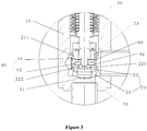
Figure 3 is a partially enlarged view showing the structure of a portion A of the electronic expansion valve inFigure 2 ; -
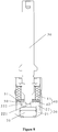
Figure 4 is a schematic sectional structural view showing cooperation between a valve stem and a valve needle of the electronic expansion valve inFigure 2 ; -
Figure 5 is a front structural view showing the cooperation between the valve stem and the valve needle inFigure 4 ; -
Figure 6 is an exploded schematic structural view showing a first silencing portion, a first sealing portion, a second sealing portion and a valve seat core of the electronic expansion valve inFigure 2 ; -
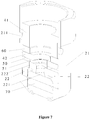
Figure 7 is a schematic sectional view showing the structure of the valve needle of the electronic expansion valve inFigure 2 ; and -
Figure 8 is a schematic longitudinal sectional structural view showing cooperation between a valve stem and a valve needle of an electronic expansion valve according to a second embodiment of the present application. - Reference Numerals in the drawings:
10 valve body, 11 first valve port, 20 valve needle, 21 valve needle body, 211 first flow passage, 22 valve seat core, 221 second valve port, 222 second flow passage, 223 flow guide groove, 23 accommodation space, 30 valve stem, 40 first silencing portion, 41 first silencing structure, 411 third interference avoiding hole, 42 second silencing structure, 421 fourth interference avoiding hole, 50 first sealing portion, 51 third flow passage, 52 first interference avoiding hole, 60 second sealing portion, 70 second silencing portion. - It should be noted that embodiments in the present application and features in the embodiments may be combined with each other without conflict. The present application will be described in detail hereinafter with reference to the drawings in conjunction with the embodiments.
- As shown in
Figures 2 to 5 , an electronic expansion valve according to a first embodiment includes: - a
valve body 10 having afirst valve port 11; - a
valve needle 20 having a closed position abutting against thefirst valve port 11 and an open position away from thefirst valve port 11, wherein a bottom of thevalve needle 20 is provided with asecond valve port 221 in communication with thefirst valve port 11, thevalve needle 20 is provided with anaccommodation space 23 and afirst flow passage 211 and asecond flow passage 222 both in communication with theaccommodation space 23, thefirst flow passage 211 is located in a side wall of thevalve needle 20 and is in communication with an outside, and thesecond flow passage 222 is located at a peripheral outer side of thesecond valve port 221 and is in communication with thesecond valve port 221; - a
valve stem 30 having at least a part of thevalve stem 30 penetrate into theaccommodation space 23, wherein thevalve stem 30 is allowed to move up and down, to adjust a flow rate at thesecond valve port 221; - a
first silencing portion 40, wherein the first silencing portion is arranged in theaccommodation space 23, so that a fluid entering from thefirst flow passage 211 is allowed to pass through thefirst silencing portion 40 to flow to thesecond flow passage 222; - a
first sealing portion 50, wherein the first sealing portion is arranged in theaccommodation space 23 and located between thefirst silencing portion 40 and thesecond flow passage 222, thefirst sealing portion 50 is provided with athird flow passage 51, and theaccommodation space 23 is in communication with thesecond flow passage 222 through thethird flow passage 51; and - a driving portion configured to drive the
valve stem 30 to move up and down; and - According to the technical solution of this embodiment, the electronic expansion valve includes a
first sealing portion 50, thefirst sealing portion 50 is arranged in theaccommodation space 23 and located between thefirst silencing portion 40 and thesecond flow passage 222, thefirst sealing portion 50 is provided with athird flow passage 51, and theaccommodation space 23 is in communication with thesecond flow passage 222 through thethird flow passage 51. When thevalve needle 20 is at the closed position and the valve stem abuts against thesecond valve port 221, the electronic expansion valve is in a small flow state. When the fluid enters theaccommodation space 23 from thefirst flow passage 211, a part of the fluid is silenced by thefirst silencing portion 40 and then flows into thethird flow passage 51, and finally flows out from thesecond flow passage 222; another part of the fluid that is not silenced by thefirst silencing portion 40 is blocked by thefirst sealing portion 50 and flows, in a direction opposite to a previous flow direction, into thefirst silencing portion 40 for noise reduction. This part of the silenced fluid flows into thethird flow passage 51 and finally flows out from thesecond flow passage 222. Therefore, with the above structure, all of the fluid entering theaccommodation space 23 from thefirst flow passage 211 enters the first silencingportion 40 for noise reduction, which improves a noise reduction effect and reduces noise of the electronic expansion valve, and thereby solving the problem of loud noise of the electronic expansion valve in the conventional art. - An operating principle of the electronic expansion valve is briefly described hereinafter.
- When the
valve stem 30 is driven to move downward by the driving portion, thevalve needle 20 comes into contact with the stop member due to its own weight and a pressure differential force. Thevalve needle 20 is able to move synchronously with thevalve stem 30 in this state due to the structure of the stop member until thevalve needle 20 is at the closed position. When thevalve needle 20 is at the closed position, thevalve needle 20 starts to separate from the stop member, at this time, thevalve stem 30 is able to move downward with respect to thevalve needle 20. When thevalve stem 30 abuts against thesecond valve port 221, the electronic expansion valve is in the small flow state. When thevalve stem 30 is driven to move upward by the driving portion, thevalve stem 30 is able to move upward with respect to thevalve needle 20 until thevalve needle 20 comes into contact with the stop member. When thevalve needle 20 is in contact with the stop member, the valve stem 30 starts to drive thevalve needle 20 to move upward together. When the motor is started to reach a fully open pulse, the whole electronic expansion valve is in a fully open state. It should be noted that, as shown inFigure 5 , thevalve stem 30 is able to move up and down within a travel range L1 by the driving of the driving portion. The above structure allows a small flow regulating section, which is easy to generate noise, to be separated as an independent unit, that is, L1 is related to an opening degree of a section where the noise is generated. - In the first embodiment, the
first sealing portion 50 is made of a polymer material or a soft metallic material. The polymer material may be rubber or plastic, and the soft metal material may be various metallic materials having plasticity and low rigidity. The above structure allows thefirst sealing portion 50, after being pressed, to be embedded into the first silencingportion 40 having an uneven surface, so that there is no gap between the first silencingportion 40 and thefirst sealing portion 50. That is, all of the fluid entering from thefirst flow passage 211 or thesecond flow passage 222 will enter the first silencingportion 40 for noise reduction, thereby improving the noise reduction effect. - As shown in
Figures 2 to 6 , in the first embodiment, thevalve needle 20 includes avalve needle body 21 and avalve seat core 22 arranged in thevalve needle body 21, theaccommodation space 23 is defined by an inner wall of thevalve needle body 21 and an upper surface of thevalve seat core 22, and both thesecond valve port 221 and thesecond flow passage 222 are arranged at the valve seat core. The above structure is simple, and easy to manufacture and assemble. - As shown in
Figure 4 , in the first embodiment, thevalve seat core 22 is further provided with aflow guide groove 223, and theflow guide groove 223 is arranged at a lower portion of thevalve seat core 22 and is in communication with thesecond flow passage 222. - As shown in
Figures 4 ,6 and7 , in the first embodiment, thefirst sealing portion 50 is a first sealing ring, the first sealing ring is clamped between thevalve seat core 22 and the first silencingportion 40, the first sealing ring is provided with a firstinterference avoiding hole 52 for avoiding thevalve stem 30, and a peripheral side wall of thefirst sealing portion 50 is fitted to the inner wall of thevalve needle 20. The above structure is simple, and easy to process. Moreover, with the above structure, a gap between thevalve seat core 22 and the first silencingportion 40 is further blocked, thereby improving the noise reduction effect. - It should be noted that, since the surface of the first silencing
portion 40 is uneven, a part of the fluid which is not silenced may flow from uneven gaps (a gap between the first silencingportion 40 and the inner wall of thevalve needle 20, and the gap between the first silencingportion 40 and the upper surface of the valve seat core 22) to thefirst flow passage 211 or thesecond flow passage 222 and then flows out, resulting in a poor noise reduction effect. Preferably, as shown inFigures 4 ,5 and7 , in the first embodiment, an outer diameter of the first sealing ring matches an inner diameter of the valve needle, and an upper surface of the first sealing ring may be embedded into the first silencingportion 40 having the uneven surface after being pressed. A lower surface of the first sealing ring abuts against the upper surface of thevalve seat core 22. With the above structure, there is no gap between the first silencingportion 40 and thevalve seat core 22, which ensures that all of the fluid entering from thefirst flow passage 211 or thesecond flow passage 222 enters the first silencingportion 40 for noise reduction, thereby improving the noise reduction effect. - It should also be noted that, the first sealing ring is made of a polymer material or a soft metallic material, and the polymer material may be rubber, plastic, etc., and the soft metallic material may be various metal materials having plasticity and low rigidity. Since the polymer material or the soft metallic material has advantages of low rigidity and high strength, the gap which may exist between the first silencing
portion 40 and thevalve seat core 22 can be effectively eliminated, thereby better improving the noise reduction effect and reducing the noise generated by the electronic expansion valve. - As shown in
Figures 4 to 7 , in the first embodiment, thesecond flow passage 222 is embodied as a first flow hole, there are multiple first flow holes, and the multiple first flow holes are arranged in a peripheral direction of thesecond valve port 221. With the above structure, a flow rate of the fluid when the electronic expansion valve is in a small flow state is increased, and the number and diameters of the first flow holes may be designed according to actual conditions. - As shown in
Figures 4 to 7 , in the first embodiment, thethird flow passage 51 is embodied as a second flow hole, there are multiple second flow holes, and the multiple second flow holes are arranged in one-to-one correspondence with the multiple first flow holes. With the above structure, the flow rate of the fluid when the electronic expansion valve is in the small flow state is increased, and the number of the second flow holes may be designed according to actual conditions. - As shown in
Figure 6 , in the first embodiment, the second flow holes are arc-shaped holes. Since the arc-shaped hole is long, with the above structure, it is easier for workers to align the second flow holes with the first flow holes during installation, which facilitates installation for the workers, and thereby improving working efficiency. - As shown in
Figures 2 to 5 , in the first embodiment, the first silencingportion 40 includes a first silencingstructure 41 and a second silencingstructure 42, the first silencingstructure 41 is located above the second silencingstructure 42, the first silencingstructure 41 blocks thefirst flow passage 211, and the second silencingstructure 42 blocks thethird flow passage 51. With the above structure, a utilization ratio of the first silencingportion 40 is improved, and thereby reducing the noise of the electronic expansion valve. - In order to further improve the noise reduction effect of the first silencing
portion 40, as shown inFigures 2 to 7 , in the first embodiment, the electronic expansion valve further includes asecond sealing portion 60, thesecond sealing portion 60 is arranged between the first silencingstructure 41 and the second silencingstructure 42, to separate the first silencingstructure 41 and the second silencingstructure 42. Specifically, when thevalve needle 20 is at the closed position and thevalve stem 30 abuts against thesecond valve port 221, the electronic expansion valve is in the small flow state. When the fluid enters from thefirst flow passage 211, a part of the fluid flows into theaccommodation space 23 after being silenced by the first silencing structure 41.The fluid flowing into theaccommodation space 23 continues to flow to the second silencingstructure 42. Another part of the fluid is blocked by thesecond sealing portion 60, so that it is repeatedly silenced in the first silencingstructure 41 until it enters theaccommodation space 23. When the fluid which has flowed into theaccommodation space 23 flows into the second silencingstructure 42 for noise reduction, a part of the fluid flows out from thesecond flow passage 222 directly through thethird flow passage 51. Another part of the fluid will be blocked by thefirst sealing portion 50 and flow into the first silencingportion 40 in a direction opposite to a previous flow direction for secondary noise reduction. This part of the fluid that is silenced flows into thethird flow passage 51 and finally flows out from thesecond flow passage 222. - When the fluid flows in from the
second flow passage 222, the fluid will enter the second silencingstructure 42 directly through thethird flow passage 51 for noise reduction, after the fluid is silenced, a part of the fluid directly enters thefluid accommodation space 23. The fluid flowing into theaccommodation space 23 continues to flow to the first silencingstructure 41. Another part of the fluid is blocked by thesecond sealing portion 60, so that it is repeatedly silenced in the second silencingstructure 42 until it flows into theaccommodation space 23. All of the fluid that has flowed into theaccommodation space 23 will flow into the first silencingportion 40 for secondary noise reduction. - The above structure has the following two advantages. With the arrangement of the
first sealing portion 50 and thesecond sealing portion 60, the first silencingportion 40 can be utilized repeatedly, which increases the utilization ratio, and improves the noise reduction effect. With the arrangement of thefirst sealing portion 50 and thesecond sealing portion 60, an effective distance through which the fluid is silenced is longer, which effectively prevents the fluid from flowing directly from the gap between the first silencingstructure 41 and the second silencingstructure 42. - It should be noted that, in the first embodiment, an annular area of the
accommodation space 23 is much larger than an area of the first flow-throughchannel 211, so that the fluid can be silenced again after flowing into theaccommodation space 23, which significantly improves the noise reduction effect. Moreover, the above technical structure is relatively simple and has good manufacturability. - As shown in
Figures 6 and7 , in the first embodiment, thesecond sealing portion 60 is a second sealing ring, and the second sealing ring is provided with a second interference avoiding hole for avoiding thevalve stem 30. A peripheral side wall of thesecond sealing portion 60 is fitted to the inner wall of thevalve needle 20. The above structure is simple, easy to process and assemble. Moreover, with the above structure, the gap between the first silencingstructure 41 and the second silencingstructure 42 is further blocked, and thereby further improving the noise reduction effect. - In the first embodiment, the
second sealing portion 60 is made of a polymer material or a soft metallic material. The polymer material may be rubber or plastic, and the soft metallic material may be various metallic materials having plasticity and low rigidity. Specifically, an outer diameter of the second sealing ring matches the inner diameter of thevalve needle 20. When being pressed, an upper surface of the second sealing ring may be embedded into the first silencingstructure 41 having an uneven surface, and a lower surface of the second sealing ring may be embedded into the second silencingstructure 42 having an uneven surface. With the above structure, there is no gap between the first silencingstructure 41 and the second silencingstructure 42, so that the effective distance through which the fluid entering the first silencingportion 40 is silenced is long, which increases the utilization ratio of the first silencingportion 40, and thereby improving the noise reduction effect of the electronic expansion valve. - As shown in
Figures 2 to 7 , in the first embodiment, the electronic expansion valve further includes a second silencingportion 70, the second silencingportion 70 is arranged below thesecond valve port 221. Specifically, when the fluid flows from thefirst flow passage 211 to thesecond flow passage 222, it is first silenced by the first silencingportion 40, and then silenced again by the second silencingportion 70. Similarly, when the fluid flows from thesecond flow passage 222 to thefirst flow passage 211, it is first silenced by the second silencingportion 70, and then silenced again by the first silencingportion 40. Therefore, with the above structure, the fluid can be silenced twice, thereby significantly improving the noise reduction effect and reducing the noise of the electronic expansion valve. - As shown in
Figure 6 , in the first embodiment, the first silencingstructure 41 is in a cylindrical shape, and a middle portion of the first silencingstructure 41 is provided with a thirdinterference avoiding hole 411 for avoiding thevalve stem 30. The second silencingstructure 42 is in an annular shape, and a middle portion of the second silencingstructure 42 is provided with a fourthinterference avoiding hole 421 for avoiding thevalve stem 30. - In the first embodiment, both the first silencing
structure 41 and the second silencingstructure 42 are mesh-like silencing elements. Preferably, the second silencingstructure 42 is supported by a material such as a fine mesh plate which can be slightly compressed, and when the second silencingstructure 42 is pressed, an uneven portion of the second silencingstructure 42 may be inserted into thethird flow passage 51. - As shown in
Figure 8 , the electronic expansion valve according to a second embodiment differs from the first embodiment in the specific structure of the first silencingportion 40. Specifically, in the second embodiment, both the first silencingstructure 41 and the second silencingstructure 42 are mesh-like silencing elements, and the first silencingstructure 41 and the second silencingstructure 42 are integrally formed, a size of a mesh opening of the first silencingstructure 41 is different from a size of a mesh opening of the second silencingstructure 42. The above structure makes the noise reduction effect better. It should be noted that, the above structure may be arranged according to actual requirements of noise reduction and flow disturbance, for example, the mesh opening of the first silencingstructure 41 may be arranged to be larger than the mesh opening of the second silencingstructure 42. - Flow processes of the fluid when the electronic expansion valve is in different states are described in detail hereinafter.
- When the
valve needle 20 is at the closed position, thevalve stem 30 abuts against thesecond valve port 221, and the fluid flows in from the first flow passage 211: - since the first silencing
structure 41 and the second silencingstructure 42 are sealingly isolated, the fluid flowing in from thefirst flow passage 211 enters theaccommodation space 23 via the first silencingstructure 41 first, and then enters thethird flow passages 51 via the second silencingstructure 42, and finally flows through the second silencingportion 70 at a bottom via thesecond flow passage 222 and flows to thefirst valve port 11. - When the
valve needle 20 is at the closed position, thevalve stem 30 begins to move away from thesecond valve port 221, and the fluid flows in from the first flow passage 211: - since the first silencing
structure 41 and the second silencingstructure 42 are sealingly isolated, the fluid flowing in from thefirst flow passage 211 enters theaccommodation space 23 via the first silencingstructure 41 first. After entering theaccommodation space 23, a part of the fluid enters thethird flow passage 51 via the second silencingstructure 42, and finally flows through the second silencingportion 70 at the bottom via thesecond flow passage 222 and flows to thefirst valve port 11. Another part of the fluid flows out from thesecond valve port 221 through an opening gap between thevalve stem 30 and thevalve seat core 22, and then flows into the second silencingportion 70 for noise reduction, and finally flows into thefirst valve port 11. - When the
valve needle 20 is at the closed position, thevalve stem 30 abuts against thesecond valve port 221, and the fluid flows in from the second flow passage 222: - the fluid flowing in from the
second flow passage 222 flows into, after passing through the second silencingportion 70, theflow guide groove 223 on thevalve seat core 22, thesecond flow passage 222, and thethird flow passage 51 in sequence, to enter the second silencingstructure 42. Since the first silencingstructure 41 and the second silencingstructure 42 are sealingly isolated, after entering theaccommodation space 23, the fluid will pass through the first silencingstructure 41 again, and finally flows out from thefirst flow passage 211. - When the
valve needle 20 is at the closed position, thevalve stem 30 begins to move away from thesecond valve port 221, and the fluid flows in from the second flow passage 222: - the fluid flowing in from the
second flow passage 222 enters the second silencingportion 70 for noise reduction, and a part of the silenced fluid flows into theflow guide groove 223 at a bottom of thevalve seat core 22, thesecond flow passage 222, and the second silencingstructure 42 in sequence, to enter theaccommodation space 23; and another part of the fluid enters theaccommodation space 23 through the opening gap between thevalve stem 30 and thevalve seat core 22. Since the first silencingstructure 41 and the second silencingstructure 42 are sealingly isolated, after entering theaccommodation space 23, the fluid will pass through the first silencingstructure 41 again, and finally flows out from thefirst flow passage 211. - A refrigeration system is further provided according to the present application, an embodiment (not shown in Figures) of the refrigeration system according to the present application includes an electronic expansion valve, which is the electronic expansion valve described above. Since the above electronic expansion valve has an advantage of low noise, the refrigeration system having the electronic expansion valve has the above advantage.
Claims (14)
- An electronic expansion valve, comprising:a valve body (10) having a first valve port (11);a valve needle (20), wherein the valve needle (20) has a closed position abutting against the first valve port (11) and an open position away from the first valve port (11), a bottom of the valve needle (20) is provided with a second valve port (221) in communication with the first valve port (11), the valve needle (20) is provided with an accommodation space (23) and a first flow passage (211) and a second flow passage (222) both in communication with the accommodation space (23), the first flow passage (211) is located in a side wall of the valve needle (20) and is in communication with an outside, and the second flow passage (222) is located at a peripheral outer side of the second valve port (221) and is in communication with the second valve port (221);a valve stem (30), wherein the valve stem (30) is arranged to allow at least a part of the valve stem (30) to penetrate into the accommodation space (23), and the valve stem (30) is movable up and down, to adjust a flow rate at the second valve port (221);a first silencing portion (40), wherein the first silencing portion (40) is arranged in the accommodation space (23), to allow a fluid entering from the first flow passage (211) to pass through the first silencing portion (40) to flow to the second flow passage (222);a first sealing portion (50), wherein the first sealing portion (50) is arranged in the accommodation space (23) and located between the first silencing portion (40) and the second flow passage (222), the first sealing portion (50) is provided with a third flow passage (51), and the accommodation space (23) is in communication with the second flow passage (222) through the third flow passage (51); anda driving portion configured to drive the valve stem (30) to move up and down; andwherein a stop member is provided between the valve stem (30) and the valve needle (20), to allow the valve needle (20) and the valve stem (30) to move synchronously when the valve needle (20) is in contact with the valve stem (30) through the stop member; and the stop member is also configured to allow the valve stem (30) to move up and down with respect to the valve needle (20) when the valve needle (20) is located at the closed position.
- The electronic expansion valve according to claim 1, wherein the first sealing portion (50) is made of a polymer material or a soft metallic material.
- The electronic expansion valve according to claim 1, wherein the valve needle (20) comprises a valve needle body (21) and a valve seat core (22) arranged in the valve needle body (21), the accommodation space (23) is defined by an inner wall of the valve needle body (21) and an upper surface of the valve seat core (22), and the second valve port (221) and the second flow passage (222) are arranged at the valve seat core (22).
- The electronic expansion valve according to claim 3, wherein the first sealing portion (50) is a first sealing ring, the first sealing ring is clamped between the valve seat core (22) and the first silencing portion (40), the first sealing portion is provided with a first interference avoiding hole (52) for avoiding the valve stem (30), and a peripheral side wall of the first sealing portion (50) is fitted to the inner wall of the valve needle (20).
- The electronic expansion valve according to claim 1, wherein the second flow passage (222) is embodied as a first flow hole, there are a plurality of first flow holes, and the plurality of the first flow holes are arranged in a peripheral direction of the second valve port (221).
- The electronic expansion valve according to claim 5, wherein the third flow passage (51) is embodied as a second flow hole, there are a plurality of second flow holes, and the plurality of the second flow holes are arranged in one-to-one correspondence with the plurality of the first flow holes.
- The electronic expansion valve according to claim 6, wherein the second flow holes are arc-shaped holes.
- The electronic expansion valve according to claim 1, wherein the first silencing portion (40) comprises a first silencing structure (41) and a second silencing structure (42), the first silencing structure (41) is located above the second silencing structure (42), the first silencing structure (41) is configured to block the first flow passage (211), and the second silencing structure (42) is configured to block the third flow passage (51).
- The electronic expansion valve according to claim 8, further comprising a second sealing portion (60), wherein the second sealing portion (60) is arranged between the first silencing structure (41) and the second silencing structure (42), to separate the first silencing structure (41) from the second silencing structure (42).
- The electronic expansion valve according to claim 9, wherein the second sealing portion (60) is a second sealing ring, the second sealing ring is provided with a second interference avoiding hole for avoiding the valve stem (30), and a peripheral side wall of the second sealing portion (60) is fitted to the inner wall of the valve needle (20).
- The electronic expansion valve according to claim 9, wherein the second sealing portion (60) is made of a polymer material or a soft metallic material.
- The electronic expansion valve according to claim 8, wherein both the first silencing structure (41) and the second silencing structure (42) are mesh-like silencing members, the first silencing structure (41) and the second silencing structure (42) are integrally formed, and a size of a mesh opening of the first silencing structure (41) is different from a size of a mesh opening of the second silencing structure (42).
- The electronic expansion valve according to claim 1, further comprising a second silencing portion (70) arranged below the second valve port (221).
- A refrigeration system, comprising an electronic expansion valve, wherein the electronic expansion valve is the electronic expansion valve according to any one of claims 1 to 13.
Applications Claiming Priority (2)
| Application Number | Priority Date | Filing Date | Title |
|---|---|---|---|
| CN201611085736.9A CN108119698B (en) | 2016-11-30 | 2016-11-30 | Electronic expansion valve and refrigeration system having the same |
| PCT/CN2017/113893 WO2018099422A1 (en) | 2016-11-30 | 2017-11-30 | Electronic expansion valve and refrigeration system having same |
Publications (3)
| Publication Number | Publication Date |
|---|---|
| EP3550193A1 EP3550193A1 (en) | 2019-10-09 |
| EP3550193A4 EP3550193A4 (en) | 2020-08-05 |
| EP3550193B1 true EP3550193B1 (en) | 2021-08-25 |
Family
ID=62227426
Family Applications (1)
| Application Number | Title | Priority Date | Filing Date |
|---|---|---|---|
| EP17875890.0A Active EP3550193B1 (en) | 2016-11-30 | 2017-11-30 | Electronic expansion valve and refrigeration system having same |
Country Status (5)
| Country | Link |
|---|---|
| EP (1) | EP3550193B1 (en) |
| JP (1) | JP6757472B2 (en) |
| KR (1) | KR102191738B1 (en) |
| CN (1) | CN108119698B (en) |
| WO (1) | WO2018099422A1 (en) |
Families Citing this family (8)
| Publication number | Priority date | Publication date | Assignee | Title |
|---|---|---|---|---|
| JP6966416B2 (en) * | 2018-12-27 | 2021-11-17 | 株式会社鷺宮製作所 | Valve device and refrigeration cycle system |
| CN109654233B (en) * | 2019-01-25 | 2024-01-16 | 浙江科博电器有限公司 | Waste water valve with anti-scale and silencing functions |
| KR102447040B1 (en) * | 2019-10-02 | 2022-09-26 | 동일기계공업 주식회사 | Integrated electronic valve for expansion and switching direction |
| PL4078051T3 (en) * | 2019-12-20 | 2024-03-04 | Danfoss A/S | Expansion valve |
| CN113324045B (en) * | 2020-02-28 | 2026-02-24 | 浙江三花智能控制股份有限公司 | Electronic expansion valve |
| CN114135714B (en) * | 2020-09-03 | 2024-04-02 | 浙江盾安人工环境股份有限公司 | Throttle valve |
| CN114811058B (en) * | 2021-12-31 | 2025-05-23 | 北京爱生科技发展有限公司 | Self-purifying blow-down valve for culture container |
| CN119665492A (en) * | 2023-04-24 | 2025-03-21 | 浙江三花智能控制股份有限公司 | Electronic expansion valve |
Family Cites Families (16)
| Publication number | Priority date | Publication date | Assignee | Title |
|---|---|---|---|---|
| JP3164480B2 (en) * | 1994-11-11 | 2001-05-08 | 太平洋工業株式会社 | Structure of electric expansion valve |
| JP4071451B2 (en) * | 2001-04-12 | 2008-04-02 | 株式会社鷺宮製作所 | Throttle device and air conditioner |
| JP4103363B2 (en) * | 2001-09-18 | 2008-06-18 | 三菱電機株式会社 | Flow control device, refrigeration cycle device, and air conditioner |
| JP4077340B2 (en) * | 2003-02-06 | 2008-04-16 | 株式会社鷺宮製作所 | Throttle valve device and air conditioner |
| JP2005331153A (en) * | 2004-05-19 | 2005-12-02 | Saginomiya Seisakusho Inc | Throttle valve device and air conditioner |
| JP2012117584A (en) * | 2010-11-30 | 2012-06-21 | Saginomiya Seisakusho Inc | Electric flow control valve |
| CN201934686U (en) * | 2010-12-07 | 2011-08-17 | 居琴 | Valve seat connecting structure for electronic expansion valves |
| CN102644785B (en) * | 2011-02-17 | 2014-04-30 | 浙江三花股份有限公司 | Electronic expansion valve |
| CN102901279B (en) * | 2011-07-27 | 2015-07-22 | 浙江三花股份有限公司 | Electronic expansion valve |
| WO2013170542A1 (en) * | 2012-05-18 | 2013-11-21 | 浙江三花股份有限公司 | Electronic expansion valve |
| CN103511636B (en) * | 2012-06-27 | 2016-04-06 | 浙江三花股份有限公司 | A kind of electric expansion valve |
| CN202971946U (en) * | 2012-12-07 | 2013-06-05 | 艾默生环境优化技术(苏州)有限公司 | Electronic expansion valve |
| JP6142181B2 (en) * | 2013-03-12 | 2017-06-07 | 株式会社テージーケー | Expansion valve and anti-vibration spring |
| CN105626876A (en) * | 2014-10-28 | 2016-06-01 | 浙江盾安人工环境股份有限公司 | Electronic expansion valve |
| CN105650337A (en) * | 2014-11-13 | 2016-06-08 | 浙江三花股份有限公司 | Electronic expansion valve |
| CN205534555U (en) * | 2016-01-26 | 2016-08-31 | 浙江三花股份有限公司 | Electronic expansion valve |
-
2016
- 2016-11-30 CN CN201611085736.9A patent/CN108119698B/en active Active
-
2017
- 2017-11-30 JP JP2019528843A patent/JP6757472B2/en active Active
- 2017-11-30 KR KR1020197017856A patent/KR102191738B1/en active Active
- 2017-11-30 WO PCT/CN2017/113893 patent/WO2018099422A1/en not_active Ceased
- 2017-11-30 EP EP17875890.0A patent/EP3550193B1/en active Active
Also Published As
| Publication number | Publication date |
|---|---|
| KR20190087527A (en) | 2019-07-24 |
| CN108119698B (en) | 2021-11-02 |
| CN108119698A (en) | 2018-06-05 |
| EP3550193A1 (en) | 2019-10-09 |
| EP3550193A4 (en) | 2020-08-05 |
| JP6757472B2 (en) | 2020-09-16 |
| KR102191738B1 (en) | 2020-12-17 |
| JP2020513512A (en) | 2020-05-14 |
| WO2018099422A1 (en) | 2018-06-07 |
Similar Documents
| Publication | Publication Date | Title |
|---|---|---|
| EP3550193B1 (en) | Electronic expansion valve and refrigeration system having same | |
| JP2021516319A (en) | Electronic expansion valve | |
| JP5696093B2 (en) | Motorized valve | |
| EP2924373B1 (en) | Electrically operated valve | |
| CN107356025B (en) | Electronic expansion valve | |
| JP4570473B2 (en) | Valve device and refrigeration cycle device | |
| CN107435754A (en) | Flow control valve | |
| JP4285155B2 (en) | Multistage electric expansion valve and refrigeration system | |
| WO2017097232A1 (en) | Two-stage electronic expansion valve | |
| CN106168304B (en) | Electric valve | |
| JP2014081046A (en) | Flow rate control valve | |
| CN106895153A (en) | Two-period form electric expansion valve | |
| JP6850364B2 (en) | Electronic expansion valve and freezing system equipped with it | |
| KR20120020046A (en) | Expansion valve | |
| CN107044543A (en) | Two-period form electric expansion valve | |
| CN104048067A (en) | Gas stove and gas flow rate control device for gas stove | |
| JP2011133139A (en) | Expansion valve | |
| CN109425150A (en) | Electric expansion valve and refrigeration system with it | |
| CN109425151B (en) | Electronic expansion valve and refrigeration system having the same | |
| CN107965952A (en) | Electric expansion valve and there is its refrigeration system | |
| KR102138432B1 (en) | Electric valve | |
| CN110939781A (en) | A two-way throttle valve | |
| WO2019146345A1 (en) | Flow regulating valve | |
| CN102818068A (en) | Valve part and electronic expansion valve using same | |
| CN108119697A (en) | Electric expansion valve and with its refrigeration system |
Legal Events
| Date | Code | Title | Description |
|---|---|---|---|
| STAA | Information on the status of an ep patent application or granted ep patent |
Free format text: STATUS: THE INTERNATIONAL PUBLICATION HAS BEEN MADE |
|
| PUAI | Public reference made under article 153(3) epc to a published international application that has entered the european phase |
Free format text: ORIGINAL CODE: 0009012 |
|
| STAA | Information on the status of an ep patent application or granted ep patent |
Free format text: STATUS: REQUEST FOR EXAMINATION WAS MADE |
|
| 17P | Request for examination filed |
Effective date: 20190618 |
|
| AK | Designated contracting states |
Kind code of ref document: A1 Designated state(s): AL AT BE BG CH CY CZ DE DK EE ES FI FR GB GR HR HU IE IS IT LI LT LU LV MC MK MT NL NO PL PT RO RS SE SI SK SM TR |
|
| AX | Request for extension of the european patent |
Extension state: BA ME |
|
| DAV | Request for validation of the european patent (deleted) | ||
| DAX | Request for extension of the european patent (deleted) | ||
| A4 | Supplementary search report drawn up and despatched |
Effective date: 20200706 |
|
| RIC1 | Information provided on ipc code assigned before grant |
Ipc: F16K 47/02 20060101AFI20200630BHEP Ipc: F16K 1/00 20060101ALI20200630BHEP Ipc: F25B 41/06 20060101ALI20200630BHEP |
|
| REG | Reference to a national code |
Ref country code: DE Ref legal event code: R079 Ref document number: 602017044937 Country of ref document: DE Free format text: PREVIOUS MAIN CLASS: F16K0047020000 Ipc: F25B0041300000 |
|
| RIC1 | Information provided on ipc code assigned before grant |
Ipc: F16K 47/02 20060101ALI20210208BHEP Ipc: F25B 41/31 20210101ALI20210208BHEP Ipc: F25B 41/35 20210101ALI20210208BHEP Ipc: F16K 1/00 20060101ALI20210208BHEP Ipc: F25B 41/30 20210101AFI20210208BHEP |
|
| GRAP | Despatch of communication of intention to grant a patent |
Free format text: ORIGINAL CODE: EPIDOSNIGR1 |
|
| STAA | Information on the status of an ep patent application or granted ep patent |
Free format text: STATUS: GRANT OF PATENT IS INTENDED |
|
| INTG | Intention to grant announced |
Effective date: 20210319 |
|
| GRAS | Grant fee paid |
Free format text: ORIGINAL CODE: EPIDOSNIGR3 |
|
| GRAA | (expected) grant |
Free format text: ORIGINAL CODE: 0009210 |
|
| STAA | Information on the status of an ep patent application or granted ep patent |
Free format text: STATUS: THE PATENT HAS BEEN GRANTED |
|
| AK | Designated contracting states |
Kind code of ref document: B1 Designated state(s): AL AT BE BG CH CY CZ DE DK EE ES FI FR GB GR HR HU IE IS IT LI LT LU LV MC MK MT NL NO PL PT RO RS SE SI SK SM TR |
|
| REG | Reference to a national code |
Ref country code: CH Ref legal event code: EP |
|
| REG | Reference to a national code |
Ref country code: IE Ref legal event code: FG4D Ref country code: AT Ref legal event code: REF Ref document number: 1424200 Country of ref document: AT Kind code of ref document: T Effective date: 20210915 |
|
| REG | Reference to a national code |
Ref country code: DE Ref legal event code: R096 Ref document number: 602017044937 Country of ref document: DE |
|
| REG | Reference to a national code |
Ref country code: LT Ref legal event code: MG9D |
|
| REG | Reference to a national code |
Ref country code: NL Ref legal event code: MP Effective date: 20210825 |
|
| REG | Reference to a national code |
Ref country code: AT Ref legal event code: MK05 Ref document number: 1424200 Country of ref document: AT Kind code of ref document: T Effective date: 20210825 |
|
| PG25 | Lapsed in a contracting state [announced via postgrant information from national office to epo] |
Ref country code: LT Free format text: LAPSE BECAUSE OF FAILURE TO SUBMIT A TRANSLATION OF THE DESCRIPTION OR TO PAY THE FEE WITHIN THE PRESCRIBED TIME-LIMIT Effective date: 20210825 Ref country code: AT Free format text: LAPSE BECAUSE OF FAILURE TO SUBMIT A TRANSLATION OF THE DESCRIPTION OR TO PAY THE FEE WITHIN THE PRESCRIBED TIME-LIMIT Effective date: 20210825 Ref country code: BG Free format text: LAPSE BECAUSE OF FAILURE TO SUBMIT A TRANSLATION OF THE DESCRIPTION OR TO PAY THE FEE WITHIN THE PRESCRIBED TIME-LIMIT Effective date: 20211125 Ref country code: PT Free format text: LAPSE BECAUSE OF FAILURE TO SUBMIT A TRANSLATION OF THE DESCRIPTION OR TO PAY THE FEE WITHIN THE PRESCRIBED TIME-LIMIT Effective date: 20211227 Ref country code: NO Free format text: LAPSE BECAUSE OF FAILURE TO SUBMIT A TRANSLATION OF THE DESCRIPTION OR TO PAY THE FEE WITHIN THE PRESCRIBED TIME-LIMIT Effective date: 20211125 Ref country code: RS Free format text: LAPSE BECAUSE OF FAILURE TO SUBMIT A TRANSLATION OF THE DESCRIPTION OR TO PAY THE FEE WITHIN THE PRESCRIBED TIME-LIMIT Effective date: 20210825 Ref country code: SE Free format text: LAPSE BECAUSE OF FAILURE TO SUBMIT A TRANSLATION OF THE DESCRIPTION OR TO PAY THE FEE WITHIN THE PRESCRIBED TIME-LIMIT Effective date: 20210825 Ref country code: HR Free format text: LAPSE BECAUSE OF FAILURE TO SUBMIT A TRANSLATION OF THE DESCRIPTION OR TO PAY THE FEE WITHIN THE PRESCRIBED TIME-LIMIT Effective date: 20210825 Ref country code: FI Free format text: LAPSE BECAUSE OF FAILURE TO SUBMIT A TRANSLATION OF THE DESCRIPTION OR TO PAY THE FEE WITHIN THE PRESCRIBED TIME-LIMIT Effective date: 20210825 Ref country code: ES Free format text: LAPSE BECAUSE OF FAILURE TO SUBMIT A TRANSLATION OF THE DESCRIPTION OR TO PAY THE FEE WITHIN THE PRESCRIBED TIME-LIMIT Effective date: 20210825 |
|
| PG25 | Lapsed in a contracting state [announced via postgrant information from national office to epo] |
Ref country code: PL Free format text: LAPSE BECAUSE OF FAILURE TO SUBMIT A TRANSLATION OF THE DESCRIPTION OR TO PAY THE FEE WITHIN THE PRESCRIBED TIME-LIMIT Effective date: 20210825 Ref country code: LV Free format text: LAPSE BECAUSE OF FAILURE TO SUBMIT A TRANSLATION OF THE DESCRIPTION OR TO PAY THE FEE WITHIN THE PRESCRIBED TIME-LIMIT Effective date: 20210825 Ref country code: GR Free format text: LAPSE BECAUSE OF FAILURE TO SUBMIT A TRANSLATION OF THE DESCRIPTION OR TO PAY THE FEE WITHIN THE PRESCRIBED TIME-LIMIT Effective date: 20211126 |
|
| PG25 | Lapsed in a contracting state [announced via postgrant information from national office to epo] |
Ref country code: NL Free format text: LAPSE BECAUSE OF FAILURE TO SUBMIT A TRANSLATION OF THE DESCRIPTION OR TO PAY THE FEE WITHIN THE PRESCRIBED TIME-LIMIT Effective date: 20210825 |
|
| PG25 | Lapsed in a contracting state [announced via postgrant information from national office to epo] |
Ref country code: DK Free format text: LAPSE BECAUSE OF FAILURE TO SUBMIT A TRANSLATION OF THE DESCRIPTION OR TO PAY THE FEE WITHIN THE PRESCRIBED TIME-LIMIT Effective date: 20210825 |
|
| REG | Reference to a national code |
Ref country code: DE Ref legal event code: R097 Ref document number: 602017044937 Country of ref document: DE |
|
| PG25 | Lapsed in a contracting state [announced via postgrant information from national office to epo] |
Ref country code: SM Free format text: LAPSE BECAUSE OF FAILURE TO SUBMIT A TRANSLATION OF THE DESCRIPTION OR TO PAY THE FEE WITHIN THE PRESCRIBED TIME-LIMIT Effective date: 20210825 Ref country code: SK Free format text: LAPSE BECAUSE OF FAILURE TO SUBMIT A TRANSLATION OF THE DESCRIPTION OR TO PAY THE FEE WITHIN THE PRESCRIBED TIME-LIMIT Effective date: 20210825 Ref country code: RO Free format text: LAPSE BECAUSE OF FAILURE TO SUBMIT A TRANSLATION OF THE DESCRIPTION OR TO PAY THE FEE WITHIN THE PRESCRIBED TIME-LIMIT Effective date: 20210825 Ref country code: EE Free format text: LAPSE BECAUSE OF FAILURE TO SUBMIT A TRANSLATION OF THE DESCRIPTION OR TO PAY THE FEE WITHIN THE PRESCRIBED TIME-LIMIT Effective date: 20210825 Ref country code: CZ Free format text: LAPSE BECAUSE OF FAILURE TO SUBMIT A TRANSLATION OF THE DESCRIPTION OR TO PAY THE FEE WITHIN THE PRESCRIBED TIME-LIMIT Effective date: 20210825 Ref country code: AL Free format text: LAPSE BECAUSE OF FAILURE TO SUBMIT A TRANSLATION OF THE DESCRIPTION OR TO PAY THE FEE WITHIN THE PRESCRIBED TIME-LIMIT Effective date: 20210825 |
|
| PG25 | Lapsed in a contracting state [announced via postgrant information from national office to epo] |
Ref country code: MC Free format text: LAPSE BECAUSE OF FAILURE TO SUBMIT A TRANSLATION OF THE DESCRIPTION OR TO PAY THE FEE WITHIN THE PRESCRIBED TIME-LIMIT Effective date: 20210825 |
|
| REG | Reference to a national code |
Ref country code: CH Ref legal event code: PL |
|
| PLBE | No opposition filed within time limit |
Free format text: ORIGINAL CODE: 0009261 |
|
| STAA | Information on the status of an ep patent application or granted ep patent |
Free format text: STATUS: NO OPPOSITION FILED WITHIN TIME LIMIT |
|
| PG25 | Lapsed in a contracting state [announced via postgrant information from national office to epo] |
Ref country code: LU Free format text: LAPSE BECAUSE OF NON-PAYMENT OF DUE FEES Effective date: 20211130 Ref country code: IT Free format text: LAPSE BECAUSE OF FAILURE TO SUBMIT A TRANSLATION OF THE DESCRIPTION OR TO PAY THE FEE WITHIN THE PRESCRIBED TIME-LIMIT Effective date: 20210825 |
|
| 26N | No opposition filed |
Effective date: 20220527 |
|
| PG25 | Lapsed in a contracting state [announced via postgrant information from national office to epo] |
Ref country code: SI Free format text: LAPSE BECAUSE OF FAILURE TO SUBMIT A TRANSLATION OF THE DESCRIPTION OR TO PAY THE FEE WITHIN THE PRESCRIBED TIME-LIMIT Effective date: 20210825 Ref country code: LI Free format text: LAPSE BECAUSE OF NON-PAYMENT OF DUE FEES Effective date: 20211130 Ref country code: CH Free format text: LAPSE BECAUSE OF NON-PAYMENT OF DUE FEES Effective date: 20211130 |
|
| PG25 | Lapsed in a contracting state [announced via postgrant information from national office to epo] |
Ref country code: IE Free format text: LAPSE BECAUSE OF NON-PAYMENT OF DUE FEES Effective date: 20211130 |
|
| PG25 | Lapsed in a contracting state [announced via postgrant information from national office to epo] |
Ref country code: CY Free format text: LAPSE BECAUSE OF FAILURE TO SUBMIT A TRANSLATION OF THE DESCRIPTION OR TO PAY THE FEE WITHIN THE PRESCRIBED TIME-LIMIT Effective date: 20210825 |
|
| P01 | Opt-out of the competence of the unified patent court (upc) registered |
Effective date: 20230530 |
|
| PG25 | Lapsed in a contracting state [announced via postgrant information from national office to epo] |
Ref country code: HU Free format text: LAPSE BECAUSE OF FAILURE TO SUBMIT A TRANSLATION OF THE DESCRIPTION OR TO PAY THE FEE WITHIN THE PRESCRIBED TIME-LIMIT; INVALID AB INITIO Effective date: 20171130 |
|
| PG25 | Lapsed in a contracting state [announced via postgrant information from national office to epo] |
Ref country code: MK Free format text: LAPSE BECAUSE OF FAILURE TO SUBMIT A TRANSLATION OF THE DESCRIPTION OR TO PAY THE FEE WITHIN THE PRESCRIBED TIME-LIMIT Effective date: 20210825 |
|
| PG25 | Lapsed in a contracting state [announced via postgrant information from national office to epo] |
Ref country code: MT Free format text: LAPSE BECAUSE OF FAILURE TO SUBMIT A TRANSLATION OF THE DESCRIPTION OR TO PAY THE FEE WITHIN THE PRESCRIBED TIME-LIMIT Effective date: 20210825 |
|
| PG25 | Lapsed in a contracting state [announced via postgrant information from national office to epo] |
Ref country code: TR Free format text: LAPSE BECAUSE OF FAILURE TO SUBMIT A TRANSLATION OF THE DESCRIPTION OR TO PAY THE FEE WITHIN THE PRESCRIBED TIME-LIMIT Effective date: 20210825 |
|
| PGFP | Annual fee paid to national office [announced via postgrant information from national office to epo] |
Ref country code: DE Payment date: 20251117 Year of fee payment: 9 |
|
| PGFP | Annual fee paid to national office [announced via postgrant information from national office to epo] |
Ref country code: GB Payment date: 20251126 Year of fee payment: 9 |
|
| PGFP | Annual fee paid to national office [announced via postgrant information from national office to epo] |
Ref country code: FR Payment date: 20251128 Year of fee payment: 9 |
|
| PGFP | Annual fee paid to national office [announced via postgrant information from national office to epo] |
Ref country code: BE Payment date: 20251120 Year of fee payment: 9 |