EP3535795B1 - Antennengrundfläche mit positiver batterieklemme - Google Patents
Antennengrundfläche mit positiver batterieklemme Download PDFInfo
- Publication number
- EP3535795B1 EP3535795B1 EP17811398.1A EP17811398A EP3535795B1 EP 3535795 B1 EP3535795 B1 EP 3535795B1 EP 17811398 A EP17811398 A EP 17811398A EP 3535795 B1 EP3535795 B1 EP 3535795B1
- Authority
- EP
- European Patent Office
- Prior art keywords
- battery
- antenna
- impedance matching
- matching circuit
- external surface
- Prior art date
- Legal status (The legal status is an assumption and is not a legal conclusion. Google has not performed a legal analysis and makes no representation as to the accuracy of the status listed.)
- Active
Links
Images




Classifications
-
- H—ELECTRICITY
- H01—ELECTRIC ELEMENTS
- H01Q—ANTENNAS, i.e. RADIO AERIALS
- H01Q1/00—Details of, or arrangements associated with, antennas
- H01Q1/48—Earthing means; Earth screens; Counterpoises
-
- H—ELECTRICITY
- H01—ELECTRIC ELEMENTS
- H01M—PROCESSES OR MEANS, e.g. BATTERIES, FOR THE DIRECT CONVERSION OF CHEMICAL ENERGY INTO ELECTRICAL ENERGY
- H01M6/00—Primary cells; Manufacture thereof
- H01M6/04—Cells with aqueous electrolyte
- H01M6/06—Dry cells, i.e. cells wherein the electrolyte is rendered non-fluid
- H01M6/08—Dry cells, i.e. cells wherein the electrolyte is rendered non-fluid with cup-shaped electrodes
-
- H—ELECTRICITY
- H01—ELECTRIC ELEMENTS
- H01M—PROCESSES OR MEANS, e.g. BATTERIES, FOR THE DIRECT CONVERSION OF CHEMICAL ENERGY INTO ELECTRICAL ENERGY
- H01M10/00—Secondary cells; Manufacture thereof
- H01M10/42—Methods or arrangements for servicing or maintenance of secondary cells or secondary half-cells
- H01M10/425—Structural combination with electronic components, e.g. electronic circuits integrated to the outside of the casing
-
- H—ELECTRICITY
- H01—ELECTRIC ELEMENTS
- H01M—PROCESSES OR MEANS, e.g. BATTERIES, FOR THE DIRECT CONVERSION OF CHEMICAL ENERGY INTO ELECTRICAL ENERGY
- H01M10/00—Secondary cells; Manufacture thereof
- H01M10/42—Methods or arrangements for servicing or maintenance of secondary cells or secondary half-cells
- H01M10/425—Structural combination with electronic components, e.g. electronic circuits integrated to the outside of the casing
- H01M10/4264—Structural combination with electronic components, e.g. electronic circuits integrated to the outside of the casing with capacitors
-
- H—ELECTRICITY
- H01—ELECTRIC ELEMENTS
- H01M—PROCESSES OR MEANS, e.g. BATTERIES, FOR THE DIRECT CONVERSION OF CHEMICAL ENERGY INTO ELECTRICAL ENERGY
- H01M10/00—Secondary cells; Manufacture thereof
- H01M10/42—Methods or arrangements for servicing or maintenance of secondary cells or secondary half-cells
- H01M10/48—Accumulators combined with arrangements for measuring, testing or indicating the condition of cells, e.g. the level or density of the electrolyte
-
- H—ELECTRICITY
- H01—ELECTRIC ELEMENTS
- H01Q—ANTENNAS, i.e. RADIO AERIALS
- H01Q1/00—Details of, or arrangements associated with, antennas
- H01Q1/44—Details of, or arrangements associated with, antennas using equipment having another main function to serve additionally as an antenna, e.g. means for giving an antenna an aesthetic aspect
-
- H—ELECTRICITY
- H01—ELECTRIC ELEMENTS
- H01Q—ANTENNAS, i.e. RADIO AERIALS
- H01Q5/00—Arrangements for simultaneous operation of antennas on two or more different wavebands, e.g. dual-band or multi-band arrangements
- H01Q5/30—Arrangements for providing operation on different wavebands
- H01Q5/307—Individual or coupled radiating elements, each element being fed in an unspecified way
- H01Q5/314—Individual or coupled radiating elements, each element being fed in an unspecified way using frequency dependent circuits or components, e.g. trap circuits or capacitors
- H01Q5/335—Individual or coupled radiating elements, each element being fed in an unspecified way using frequency dependent circuits or components, e.g. trap circuits or capacitors at the feed, e.g. for impedance matching
-
- H—ELECTRICITY
- H01—ELECTRIC ELEMENTS
- H01Q—ANTENNAS, i.e. RADIO AERIALS
- H01Q5/00—Arrangements for simultaneous operation of antennas on two or more different wavebands, e.g. dual-band or multi-band arrangements
- H01Q5/50—Feeding or matching arrangements for broad-band or multi-band operation
-
- H—ELECTRICITY
- H01—ELECTRIC ELEMENTS
- H01M—PROCESSES OR MEANS, e.g. BATTERIES, FOR THE DIRECT CONVERSION OF CHEMICAL ENERGY INTO ELECTRICAL ENERGY
- H01M10/00—Secondary cells; Manufacture thereof
- H01M10/42—Methods or arrangements for servicing or maintenance of secondary cells or secondary half-cells
- H01M10/425—Structural combination with electronic components, e.g. electronic circuits integrated to the outside of the casing
- H01M2010/4271—Battery management systems including electronic circuits, e.g. control of current or voltage to keep battery in healthy state, cell balancing
-
- H—ELECTRICITY
- H01—ELECTRIC ELEMENTS
- H01M—PROCESSES OR MEANS, e.g. BATTERIES, FOR THE DIRECT CONVERSION OF CHEMICAL ENERGY INTO ELECTRICAL ENERGY
- H01M10/00—Secondary cells; Manufacture thereof
- H01M10/42—Methods or arrangements for servicing or maintenance of secondary cells or secondary half-cells
- H01M10/425—Structural combination with electronic components, e.g. electronic circuits integrated to the outside of the casing
- H01M2010/4278—Systems for data transfer from batteries, e.g. transfer of battery parameters to a controller, data transferred between battery controller and main controller
-
- Y—GENERAL TAGGING OF NEW TECHNOLOGICAL DEVELOPMENTS; GENERAL TAGGING OF CROSS-SECTIONAL TECHNOLOGIES SPANNING OVER SEVERAL SECTIONS OF THE IPC; TECHNICAL SUBJECTS COVERED BY FORMER USPC CROSS-REFERENCE ART COLLECTIONS [XRACs] AND DIGESTS
- Y02—TECHNOLOGIES OR APPLICATIONS FOR MITIGATION OR ADAPTATION AGAINST CLIMATE CHANGE
- Y02E—REDUCTION OF GREENHOUSE GAS [GHG] EMISSIONS, RELATED TO ENERGY GENERATION, TRANSMISSION OR DISTRIBUTION
- Y02E60/00—Enabling technologies; Technologies with a potential or indirect contribution to GHG emissions mitigation
- Y02E60/10—Energy storage using batteries
Definitions
- the disclosure generally relates to apparatus and methods to use external surfaces of a battery as a ground plane for an antenna in a communication system and, more particularly, to use a positive terminal and electrically conductive external surface, typically the metal battery can or casing, of a battery as a ground plane for an antenna that communicates battery status information.
- On-cell battery fuel gauges may require a user to press two buttons, wait several seconds, and then observe an indication of the state of charge of the battery. Such a solution may require removing the batteries from the device and checking the battery to decide whether it is necessary to replace the battery. As such, solutions that avoid removal of a battery from a device to check the remaining capacity provide significant advantages for consumers.
- a battery status may be detected by remote indication using an analog to digital converter (ADC) and a Near Field Communication (NFC) Integrated Circuit (IC) together with a magnetic diverter and a thin foil antenna on the battery label.
- ADC analog to digital converter
- NFC Near Field Communication
- IC Integrated Circuit
- Application software for example executing on a smart phone, may be used to receive battery status information remotely.
- battery status information may include the battery voltage that is then used to provide an indication of battery status to the user.
- NFC detection range may in some embodiments be limited to several centimeters.
- battery cells may be constructed with a conductive metal can, for example constructed with steel, particularly primary alkaline batteries available to consumers.
- the presence of such metal surfaces near an antenna installed on a wireless transmitter circuit may detune the antenna significantly, deteriorating performance and reducing the usable range to a receiving device.
- US 2015/349391 discloses an indicator circuit that is attached to both ends of a battery.
- the battery includes a positive terminal and a negative terminal.
- An integrated circuit is electrically coupled to the positive terminal and to the negative terminal, which are at opposite ends of the battery.
- One exemplary embodiment includes an apparatus that includes a positive terminal of a battery having a first electrically conductive external surface with a first surface area; a negative terminal of a battery having a second electrically conductive external surface with a second surface area; and an antenna impedance matching circuit, electrically connected to a communication circuit, an antenna, and the positive terminal of the battery.
- the first surface area is greater than the second surface area
- Another exemplary embodiment includes a method, that includes providing a positive terminal of a battery having a first electrically conductive external surface with a first surface area; providing a negative terminal of a battery having a second electrically conductive external surface with a second surface area less than the first surface area; providing an antenna impedance matching circuit; and electrically connecting the antenna impedance matching circuit to the positive terminal of the battery.
- Yet another exemplary embodiment includes a method that includes providing a negative terminal of a primary alkaline battery with a first surface area; providing a positive terminal of a primary alkaline battery as a ground plane of an antenna, the positive terminal comprising a second surface area greater than the first surface area; providing an antenna impedance matching circuit; electrically connecting the antenna impedance matching circuit to the positive terminal of the primary alkaline battery; electrically connecting the antenna impedance matching circuit to a communication circuit and an antenna; and calculating data relating to the remaining capacity of the battery including corrections for load on the battery related to transmission and reception of data using the communication circuit, the antenna impedance matching circuit, the antenna, and the positive terminal of the primary alkaline battery.
- the anode can comprise zinc and the cathode can comprise manganese oxide.
- the battery is a primary Zinc-Carbon battery, the battery comprising an anode, a cathode, and an electrolyte.
- the battery may be a primary lithium battery.
- the battery can be a secondary battery, for example, a secondary battery such as a nickel metal hydride (NiMH) battery, a nickel cadmium (NiCad) battery, a silver/zinc battery, a nickel/zinc battery, or a lithium solid state rechargeable battery.
- NiMH nickel metal hydride
- NiCad nickel cadmium
- the terminals of the battery switch during charging or discharging.
- any battery chemistry may be used in accordance with the disclosure provided that the electrically conductive metal battery can is electrically connected to the positive terminal.
- any one or more of the foregoing aspects of an apparatus or a method may further include any one or more of the following optional forms.
- the first electrically conductive external surface electrically connects to a cathode of a primary alkaline battery
- the second electrically conductive external surface electrically connects to an anode of a primary alkaline battery
- a ground plane of the communication circuit electrically connects to the negative terminal of the battery.
- the antenna impedance matching circuit comprises a balun configured to convert, for a first communication frequency, an input impedance of the impedance matching circuit to an output impedance of the impedance matching circuit.
- an electrical length of the first electrically conductive external surface is greater than 0.25 of a wavelength of a signal transmitted by the communication circuit into the antenna impedance matching circuit, and the electrical length of the first electrically conductive external surface is a physical length of the first electrically conductive external surface multiplied by the ratio of (i) the propagation time of the signal through the first electrically conductive external surface to (ii) the propagation time of the signal in free space over a distance equal to the physical length of the first electrically conductive external surface.
- the electrical length of the first electrically conductive external surface is configured to minimize a reflected power from the antenna back into the antenna impedance matching circuit as a result of the communication circuit transmitting the signal.
- the antenna impedance matching circuit comprises at least one of (i) a capacitor and (ii) an inductor, and at least one of (i) the capacitor and (ii) the inductor are electrically connected between the communication circuit and the positive terminal of the battery.
- the battery is a primary alkaline battery, the battery comprising an anode, a cathode, and an alkaline electrolyte.
- the anode can comprise zinc and the cathode can comprise manganese oxide.
- the battery is a primary Zinc-Carbon battery, the battery comprising an anode, a cathode, and an electrolyte.
- the battery may be a primary lithium battery.
- the battery can be a secondary battery, for example, a secondary battery such as a nickel metal hydride (NiMH) battery, a nickel cadmium (NiCad) battery, a silver/zinc battery, a nickel/zinc battery, a lithium-ion or a lithium solid state rechargeable battery.
- a secondary battery such as a nickel metal hydride (NiMH) battery, a nickel cadmium (NiCad) battery, a silver/zinc battery, a nickel/zinc battery, a lithium-ion or a lithium solid state rechargeable battery.
- NiMH nickel metal hydride
- NiCad nickel cadmium
- silver/zinc battery a silver/zinc battery
- nickel/zinc battery a lithium-ion or a lithium solid state rechargeable battery.
- any battery chemistry may be used in accordance with the disclosure provided that the exterior metal battery can is electrically connected to the positive terminal.
- the balun comprises a first winding and a second winding around a magnetic ferrite, a first end of the first winding is electrically connected to the antenna, and a second end of the first winding is electrically connected to the positive terminal of the battery.
- a first end of the second winding is electrically connected to the communication circuit, and a second end of the second winding is electrically connected to the antenna.
- Another optional form includes electrically connecting the antenna impedance matching circuit to a communication circuit and an antenna.
- Yet another optional form includes electrically connecting a ground plane of the communication circuit to the negative terminal of the battery.
- Still another optional form includes providing a balun configured to convert an input impedance encountered by a signal transmitted by the communication circuit into the impedance matching circuit to an output impedance.
- Still another optional form includes providing the first electrically conductive external surface with an electrical length greater than 0.25 of a wavelength of a signal transmitted by the communication circuit into the antenna impedance matching circuit.
- Still another optional form includes providing the first electrically conductive external surface with an electrical length that minimizes a reflected power from the antenna back into the antenna impedance matching circuit as a result of the communication circuit transmitting the signal.
- Still another optional form includes providing the antenna impedance matching circuit with at least one of (i) a capacitor and (ii) an inductor, and electrically connecting at least one of (i) the capacitor and (ii) the inductor between a communication circuit and the positive terminal of the battery.
- Still another optional form includes providing a primary alkaline battery comprising an anode, a cathode, and an alkaline electrolyte; electrically connecting the cathode of the battery to the first electrically conductive external surface of a battery; and electrically connecting the anode of the battery to the second electrically conductive external surface of a battery.
- the anode can comprise zinc and the cathode can comprise manganese oxide.
- the battery may be a primary lithium battery.
- the battery can be a secondary battery, for example, a secondary battery such as a nickel metal hydride (NiMH) battery, a nickel cadmium (NiCad) battery, a silver/zinc battery, a nickel/zinc battery, or a lithium ion, lithium polymer or a lithium solid state rechargeable battery.
- a secondary battery such as a nickel metal hydride (NiMH) battery, a nickel cadmium (NiCad) battery, a silver/zinc battery, a nickel/zinc battery, or a lithium ion, lithium polymer or a lithium solid state rechargeable battery.
- NiMH nickel metal hydride
- NiCad nickel cadmium
- silver/zinc battery a nickel/zinc battery
- a lithium ion, lithium polymer or a lithium solid state rechargeable battery any battery chemistry may be used in accordance with the disclosure provided that the exterior metal battery can is electrically connected to the positive terminal.
- Still another optional form includes providing a balun comprising a first winding and a second winding around a magnetic ferrite such that an output impedance of the balun approximates an input impedance of the antenna; electrically connecting a first end of the first winding to the antenna; and electrically connecting a second end of the first winding to the positive terminal of the battery.
- Still another optional form includes electrically connecting a first end of the second winding to the communication circuit; and electrically connecting a second end of the second winding to the antenna.
- Exemplary embodiments may include computer-implemented methods that may, in other embodiments, include apparatus configured to implement the method, and/or non-transitory computer readable mediums comprising computer-executable instructions that cause a processor to perform the method.
- One embodiment of the present disclosure includes enabling an RF wireless sensor to operate on a battery with positive-biased case, or can, to improve the range, or maximum reading distance, between the transmitter installed on the battery and the reader.
- the reader may include a smart phone, tablet, local network hub, or another embodiment of a computing device.
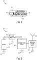
- Figure 1 illustrates an exemplary apparatus 100 including a consumer alkaline battery 110, and an installed printed circuit board 120 that includes a variety of interconnected components that transmit a status of a battery.
- the printed circuit board 120 may be electrically connected to the cathode of the battery 130, and the anode of the battery 140, for example by making a low-impedance connection through wires, clips, or otherwise.
- Consumer alkaline batteries 110 in particular, may benefit from the installed printed circuit board 120 because alkaline batteries often require replacement in consumer electronic devices and trips to a retailer to purchase new batteries, and as such battery status information is particularly relevant.
- the active material of the anode may comprise zinc.
- the active material of the cathode may comprise a composition comprising manganese oxide and/or manganese dioxide.
- Manganese dioxide may comprise gamma manganese dioxide, lambda manganese dioxide, or combinations thereof.
- Manganese dioxide may be prepared electrolytically as electrolytic manganese dioxide (EMD) or chemically as chemical manganese dioxide (CMD).
- EMD electrolytic manganese dioxide
- CMD chemical manganese dioxide
- Manganese dioxide is also available as natural manganese dioxide (NMD), however, NMD typically is not employed in alkaline batteries. Mixtures of more than one of EMD, CMD, and NMD may be used. Accordingly, as used herein, manganese dioxide refers to EMD, CMD, NMD and combinations thereof.
- Active material compositions for cathodes comprising manganese dioxide may contain at least about 91 percent by weight (e.g., impurities such as sulfate salts, various metals and the like are present in an amount no greater than 9% by weight).
- EMD is provided as a composition comprising a high purity, high density, gamma manganese dioxide, and is desirable as a cathode active material for alkaline cells.
- CMD has also been used as electrochemically active cathode material in electrochemical cells including alkaline cells and heavy-duty cells; however, commercial chemical processes yield high purity MnO 2 but do not yield densities of MnO 2 comparable to that of EMD.
- EMD has become the most widely used form of battery grade MnO 2 , particularly for alkaline and lithium cells, since in such application it has become most desirable to employ high density MnO 2 to increase the capacity of these cells.
- EMD is typically manufactured from direct electrolysis of a bath of manganese sulfate and sulfuric acid.
- Battery grade CMD may be produced via the "Sedema process," by employing the reaction mixture of MnSO 4 and an alkali metal chlorate, preferably NaClO 3 , as disclosed by U.S. Pat. No. 2,956,860 (Welsh).
- Distributors of manganese dioxides include Tronox, Erachem, Tosoh, Delta Manganese, and Xiangtan.
- Conventional battery grade manganese dioxide-containing compositions do not have a true stoichiometric formula MnO 2 , but are better represented by the formula MnOx, wherein x is typically between about 1.92 to 1.96, corresponding to a manganese valence of between about 3.84 and 3.92.
- Conventional EMD may typically have a value for x of about 1.95 or 1.96, corresponding to a manganese valence of 3.90 and 3.92, respectively.
- Conventional EMD also has a real density of between about 4.4 and 4.6 g/cm3.
- the printed circuit board 120 installed on other primary batteries or secondary batteries, for example, a primary lithium-ion battery, or a secondary battery such as a nickel metal hydride (NiMH) battery, a nickel cadmium (NiCad) battery, a silver/zinc battery, a nickel/zinc battery, or a lithium solid state rechargeable battery.
- a primary lithium-ion battery or a secondary battery
- NiMH nickel metal hydride
- NiCad nickel cadmium
- silver/zinc battery a nickel/zinc battery
- a lithium solid state rechargeable battery the terminals of the battery switch during charging or discharging.
- the electrically conductive external surface of the battery comprises the positive terminal while discharging and being used to power a device.
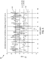
- FIG. 2 illustrates a block diagram of an exemplary apparatus 200 to detect and transmit battery status information.
- the apparatus 200 includes a battery 210, with an anode of the battery electrically connected to a ground 215, and a cathode of the battery electrically connected to an input of a voltage regulator 220.
- the voltage regulator 220 may step-up a single alkaline cell voltage to a suitable voltage to power a communications circuit 230, for example to 2.4 volts or 3 volts.
- the voltage regulator 220 may be electrically connected to a ground 225 with a low impedance electrical path to the ground 215 and the anode of the battery 210.
- the voltage of the battery cell may be offset at the input of an analog to digital converter (ADC) to effectively improve the resolution of the ADC.
- ADC analog to digital converter
- the communications circuit 230 may include a ground plane with a low impedance path to a ground 235.
- the ground 235 may share a low impedance path with voltage regulator ground 225, and the anode of the battery ground 215 to provide an appropriate electrical reference for proper functioning of the ADC disposed within the communications circuit 230.
- a ground plane of the digital circuitry of the communications circuit 230 may be electrically isolated with a relatively high impedance from a ground plane of the radio frequency transmission circuitry.
- a transmitter disposed within the communications circuit 230 may include a balanced connection to an impedance matching circuit 240.
- the connection between the communications circuit 230 and the impedance matching circuit 240 may include an unbalanced connection, with an impedance of 50 ohms, or otherwise as a characteristic input impedance to the impedance matching circuit 240.
- the impedance matching circuit 240 is configured to convert an input impedance encountered by the communications circuit 230 to an output impedance for a particular frequency, using a variety of passive and active electrical components.
- the output impedance of the impedance matching circuit 240 may approximate the characteristic input impedance of an antenna 250 and any associated wiring or electrical connections.
- the impedance matching circuit may be configured to minimize a reflected power from the antenna 250 as a result of a signal transmitted at a particular frequency, or set of frequencies, from the communications circuit.
- Embodiments of the impedance matching circuit 240 may include one or a plurality of connections to a ground 245.
- the ground 245 may include a low impedance path to the grounds 235, 225, and 215 of the remainder of the apparatus 200.
- the ground 245 of the impedance matching circuit 240 may include a ground plane of the antenna 250.
- the ground plane of the antenna 250 may include the anode of the battery 210 and an electrical length of the anode of the battery 210 may be significantly less than 0.25 the wavelength of a signal transmitted by the communications circuit 230 into the impedance matching circuit 240.
- the transmitter installed on the battery may include a Bluetooth® Low Energy wireless sensor, for example based on the Texas Instruments CC2540 integrated circuit.
- the transmitter may include a UHF transceiver for exchanging data over short distances.
- the transmitter may include a voltage booster, or voltage regulator to increase the voltage of the single alkaline cell.
- Such an embodiment may include a printed circuit board installed in proximity to the battery 210, due to space constraints in the battery cavity of most devices. Attachment springs may provide battery an electrical connection to allow an electrical potential for measurement and also power supply to the communications circuit 230.
- Proximity of metal to the antenna 250 may detune the antenna 250 away from a frequency range of interest and negatively affect signal transmission and reception. As the distance between the sensor and the battery 210 is reduced, due to space constraints, the detuning effect becomes more pronounced.
- the RF transceiver may be grounded to the positive power supply rail, or the cathode of the battery 210, to make use of the relatively larger cathode terminal, or battery case, as a more effective ground plane. In this case other metal objects, such as additional battery cells and metal parts of the device near the monitored battery, may not interfere substantially with the tuned system of antenna and battery.
- One exemplary embodiment of the present disclosure includes a universal reusable battery remote indication system that includes one or more silicon integrated circuits that contain an analog to digital converter (ADC) and a communications circuit such as Bluetooth® Low Energy transceiver, Ultra High Frequency (UHF) passive or active Radio Frequency Identification (RFID), WiFi, Zigbee or other means of RF communications, an antenna and resistors and/or capacitors and other components that may be needed for the operation of the system.
- ADC analog to digital converter
- UHF Ultra High Frequency
- RFID Radio Frequency Identification
- WiFi Wireless Fidelity
- Zigbee Zigbee or other means of RF communications
- antenna and resistors and/or capacitors and other components that may be needed for the operation of the system.
- Snap-on attachment of the indication system to the battery causes an electrical connection to the battery terminals, or flexible connections can also be used.
- Options may include double-sided flexible Printed Circuit Boards (PCBs) inserted between the battery and the device battery contact and electrically connected between the two sides, or flexible wires with conductive magnets to attach to the device battery terminals.
- PCBs Printed Circuit Boards
- a battery indicator may connect to and communicate with a reader or receiver, to include a smart phone or other BLE, RFID, UHF, WiFi or similar enabled communication device.
- a software application executing on the reader may display the battery status, for example voltage, impedance, load, distance, temperature, time or other parameters. The software application may interpret these parameters to provide a user of the application an indication of battery status and/or a recommendation of when to replace or recharge the battery.
- One embodiment of the present disclosure includes a single-cell BLE Monitor (Bluetooth® Low-Energy also known as Bluetooth® 4.xx or “Smart”) wherein the electronics are integrated in an ASIC (Application Specific Integrated Circuit) with common ground (DC/DC, ADC and RF) connected to the positive power supply rail or cathode of the battery.
- the antenna may be placed on the outer side of the sensor PCB (printed or integrated) and may be tuned to a fixed position versus the battery cell, which may be at a distance one PCB thickness plus the battery label thickness.
- An incorporated voltage boost converter may enable operation down to 0.8V - 0.9V.
- the board may include two snap-on battery attachments that provide power and voltage measurement connections between battery and sensor.
- the sensor may attach to a single battery cell and may be placed in a device in non-interfering way between the other battery cells.
- the assembly may rotate to the most suitable position, depending on the battery compartment specifics.
- the battery attachment may, in some embodiments, be customized to a specific battery type.
- the BLE battery monitor may be read wirelessly, using a BLE enabled smart phone with an integrated reader software application.
- the reader software application may display distance to the devices, assisting the user to locate the devices by moving and watching the RF signal strength increasing (indicating closer) or decreasing (indicating further).
- the functionality of the Reusable Wireless Battery Monitor may not be limited to indication of battery state of charge and distance to the device.
- the BLE module may include a built-in MCU that can be programmed to a variety of additional functions, such as battery impedance or internal resistance measurement (state of health), temperature, pressure, leakage, safety and low-battery alerts, charge control, power management functions, or other battery related characteristics.
- FIG. 3 illustrates one exemplary embodiment of the present disclosure that includes a block diagram of an apparatus 300.
- the apparatus 300 includes a battery 310 with a negative terminal of the battery electrically connected with a low impedance to a ground 360.
- a positive terminal of the battery 310 may be electrically connected with a low impedance to a voltage regulator 320 and one or more ground connections of an impedance matching circuit 340.
- the impedance matching circuit 340 may include a variety of passive electrical components, such as capacitors, resistors, and inductors, that together are configured to convert an input impedance of the impedance matching circuit 340 to an output impedance of the impedance matching circuit 340.
- the input to the impedance matching circuit 340 may include a balanced differential pair of conductors, and the output includes an unbalanced output and variety of a ground connections.
- other alternative embodiments may include unbalanced inputs, balanced outputs, or other combinations therein.
- the communications circuit 330 may include one or more analog to digital converters (ADCs) to receive an electrical potential from the battery 310 and convert the analog potential to a digital signal for transmission.
- ADCs analog to digital converters
- the communications circuit may convert the analog potential from the battery 310 to directly modulate an RF signal without an ADC to modulate an RF signal solely with the electric potential, or current provided by the cell of the battery 310.
- the communications circuit 330 may share a low impedance ground connection 360 with the anode of the battery 310.
- the impedance matching circuit 340 may electrically connect to an antenna 350, as illustrated with an unbalanced connection, for example with a 50 ohm impedance.
- Such embodiments may include antennas 350 that require an effective ground plane to radiate RF energy in a relatively omnidirectional pattern and prevent reflected power back into the communications circuit 330 or impedance matching circuit 340.
- the cathode of the battery 310 may act as a ground plane of the antenna 350.
- the cathode of the battery 310 may comprise a majority of the external surface area of the battery and provide an electrical length greater than 0.25 of the wavelength of transmitted signal from the communications circuit 330 into the impedance matching circuit 340.
- One implementation of the embodiment illustrated in Figure 3 may include the apparatus 300 integrated into a flexible assembly in a manner that it does not interfere with an available battery cavity.
- Such an embodiment may be applied to, for example, a AA, AAA, C, or D battery types without further modifications.
- a BLE Transceiver antenna impedance matching circuit may be grounded to the positive power supply rail, or the grounded ends of inductors and capacitors within the impedance matching circuit.
- the remainder of the apparatus may be grounded to the negative power supply rail, or anode of the battery. In such an embodiment, the detuning caused by proximity to the battery's metal case is eliminated.
- an output impedance matching balun which may also be a DC blocking component, can be grounded to the positive battery can.
- Figure 4 illustrates a block diagram of an apparatus 400 that includes a battery 410, likewise with the cathode of the battery 410 electrically connected to a voltage regulator 420 and the anode of the battery 410 electrically connected to a ground 460.
- the voltage regulator functions in a similar way as the embodiment of Figure 3 , together with the communications circuit 430 to communicate a status of the battery 410.
- the communications circuit 430 may share a ground connection 460 with the anode of the battery to function effectively.
- the embodiment illustrated in Figure 4 includes an impedance matching circuit 440 that includes a balun 445 that converts a balanced signal from the communications circuit 430 to an unbalanced signal for an antenna 450.
- the negative end of the unbalanced end of the balun 445 may be electrically connected to the cathode of the battery to effectively use the cathode of the battery as a ground plane for the antenna 450.
- the balun 445 may include a balanced and unbalanced windings around a magnetic ferrite, configured as necessary to convert a balanced input impedance to an unbalanced output impedance. As illustrated in Figure 4 , both ends of the balanced connection may be electrically connected to the communications circuit 430, one end of the unbalanced winding electrically connected to the antenna 450, and one end of the unbalanced winding electrically connected to the cathode of the battery.
- the sensor module and hence the antenna which are, for example, printed on an outer side of the PCB or surface-mounted chip antenna, may remain at a fixed small distance from the metal battery can or cathode of the battery 410 and the balun 445 may be tuned specifically for that distance.
- the battery length e.g., 50 mm for AA and 45 mm for AAA sizes respectively
- the half wavelength e.g., 61.2 mm
- a center 2.45 GHz carrier frequency may form an effective ground plane for the antenna 450.
- FIG. 5 illustrates a received signal strength indication (RSSI) graph 500 that represents the received signal strength 520 from a Bluetooth Low-Energy sensor mounted on a Duracell alkaline AA battery, measured with an iPhone 6 at 20 feet away using a Texas Instruments "Sensor Tag” app for a variety of samples 510 plotted using the negative terminal as a ground plane 530, as compared with the positive terminal as the ground plane 540.
- RSSI received signal strength indication
- the received RF power, using the cathode as the ground plane approximates at -85 decibels over one milliwatt (dBm), compared to -95 dBm when using the anode of the battery as a ground plane.
- the received signal strength may determine if communications will be established and if data packets are successfully exchanged between the sensor and the reader, for example between the battery and the smart phone. Stronger signals result in a better range, or maximum distance, between the sensor and the reader, or alternatively lower power consumption of the sensor for the same distance.
- the average current drain of the sensor may be limited to about 10 microamps, if several years of service life are desired without significant reduction of battery life.
- Figures 6 and 7 illustrate polar RSSI plots for a horizontal orientation 600 and vertical orientation 700 with the results of further testing performed with two AA alkaline cells side by side and the voltage sensor board mounted on one of them.
- the device was rotated for each of the horizontal and vertical orientation in four relative directions, 0 degrees for axis 610 and 710, 90 degrees for axes 620 and 720, 180 degrees for axes 630 and 730, and 270 degrees for axes 640 and 740.
- the averages of the RSSI were taken from 60 points for each direction over 1 minute period (one sample per second).
- test results show consistent significant advantage of the cathode, or positive terminal ground plane, as indicated by plot 660 and 760, versus the anode, or negative terminal ground plane, as indicated by plot 650 and 750.
- the advantage of positive terminal grounding was further confirmed with other devices and metal objects in proximity to the sensor.
- Figure 8 illustrates a block diagram 800 that represents one embodiment of a method to fabricate and/or use the positive terminal of a battery as an antenna ground plane.
- the block diagram 800 includes providing a positive terminal of a battery having a first electrically conductive external surface with a first surface area (block 805).
- the block diagram 800 includes providing a negative terminal of a battery having a second electrically conductive external surface with a second surface area less than the first surface area (block 815).
- the antenna impedance matching circuit may be electrically connected to the positive terminal of the battery (block 845).
- inventions include electrically connecting the antenna impedance matching circuit to a communication circuit and an antenna. Furthermore, alternative embodiments include electrically connecting a ground plane of the communication circuit to the negative terminal of the battery. Still further, alternative embodiments include providing a balun configured to convert an input impedance encountered by a signal transmitted by the communication circuit into the impedance matching circuit to an output impedance. Other embodiments include providing the first electrically conductive external surface of the battery with an electrical length greater than 0.25 of a wavelength of a signal transmitted by the communication circuit into the antenna impedance matching circuit.
- Alternative embodiments include providing the first electrically conductive external surface of the battery with an electrical length that minimizes a reflected power from the antenna back into the antenna impedance matching circuit as a result of the communication circuit transmitting the signal. Still further, embodiments include providing the antenna impedance matching circuit with at least one of (i) a capacitor and (ii) an inductor, and electrically connecting at least one of (i) the capacitor and (ii) the inductor between a communication circuit and the positive terminal of the battery.
- embodiments include providing an alkaline primary battery comprising an anode, a cathode, and an alkaline electrolyte; electrically connecting the cathode of the battery to the first electrically conductive external surface of a battery; and electrically connecting the anode of the battery to the second electrically conductive external surface of a battery. Still further, embodiments include providing a balun comprising a first winding and a second winding around a magnetic ferrite such that an output impedance of the balun approximates an input impedance of the antenna; electrically connecting a first end of the first winding to the antenna; and electrically connecting a second end of the first winding to the first electrically conductive external surface of the battery.
- Yet another embodiment includes electrically connecting a first end of the second winding to the communication circuit; and electrically connecting a second end of the second winding to the antenna.
- the RF antenna may be kept at a fixed distance from the battery case to form a tuned radiator with the battery can as a ground plane.
- the circuit board may be protected by an enclosure in the form of a triangular or trapezoid prism or other shape for a better fit between two of the round cylindrical battery cells, and to assure consistent antenna location.
- the antenna impedance matching components may be switched from negative to positive ground to effectively turn the battery can into a ground plane.
- a 2.45 GHz Impedance Matched Balun such as the BPF P/N2450BM15A0002 from High Frequency RF Solutions, may be grounded to the battery case (the positive power supply rail) instead of the common negative ground.
- a DC block may not be required for the balun grounding, its function may not be affected by the change in balun grounding.
- the antenna and the alkaline battery case as a ground plane in such an embodiment may form an optimum RF radiator.
- the sensor module may in some embodiments be permanently attached internally in the battery-powered device.
- All of the foregoing computer systems may include additional, less, or alternate functionality, including that discussed herein.
- All of the computer-implemented methods may include additional, less, or alternate actions, including those discussed herein, and may be implemented via one or more local or remote processors and/or transceivers, and/or via computer-executable instructions stored on computer-readable media or medium.
- the processors, transceivers, mobile devices, service terminals, servers, remote servers, database servers, heuristic servers, transaction servers, and/or other computing devices discussed herein may communicate with each via wireless communication networks or electronic communication networks.
- the communication between computing devices may be wireless communication or data transmission over one or more radio links, or wireless or digital communication channels.
- the service provider remote server may provide the functionality discussed herein, including security, fraud, or other monitoring, and generate recommendations to the customer and/or generate alerts for the customers in response to abnormal activity being detected.
- routines, subroutines, applications, or instructions may constitute either software (e.g., code embodied on a machine-readable medium or in a transmission signal) or hardware.
- routines, etc. are tangible units capable of performing certain operations and may be configured or arranged in a certain manner.
- one or more computer systems e.g., a standalone, client or server computer system
- one or more hardware modules of a computer system e.g., a processor or a group of processors
- software e.g., an application or application portion
- a hardware module may be implemented mechanically or electronically.
- a hardware module may comprise dedicated circuitry or logic that is permanently configured (e.g., as a special-purpose processor, such as a field programmable gate array (FPGA) or an application-specific integrated circuit (ASIC)) to perform certain operations.
- a hardware module may also comprise programmable logic or circuitry (e.g., as encompassed within a general-purpose processor or other programmable processor) that is temporarily configured by software to perform certain operations. It will be appreciated that the decision to implement a hardware module mechanically, in dedicated and permanently configured circuitry, or in temporarily configured circuitry (e.g., configured by software) may be driven by cost and time considerations.
- the term "hardware module” should be understood to encompass a tangible entity, be that an entity that is physically constructed, permanently configured (e.g., hardwired), or temporarily configured ( e.g., programmed) to operate in a certain manner or to perform certain operations described herein.
- hardware modules are temporarily configured (e.g., programmed)
- each of the hardware modules need not be configured or instantiated at any one instance in time.
- the hardware modules comprise a general-purpose processor configured using software
- the general-purpose processor may be configured as respective different hardware modules at different times.
- Software may accordingly configure a processor, for example, to constitute a particular hardware module at one instance of time and to constitute a different hardware module at a different instance of time.
- Hardware modules may provide information to, and receive information from, other hardware modules. Accordingly, the described hardware modules may be regarded as being communicatively coupled. Where multiple of such hardware modules exist contemporaneously, communications may be achieved through signal transmission ( e.g., over appropriate circuits and buses) that connect the hardware modules. In embodiments in which multiple hardware modules are configured or instantiated at different times, communications between such hardware modules may be achieved, for example, through the storage and retrieval of information in memory structures to which the multiple hardware modules have access. For example, one hardware module may perform an operation and store the output of that operation in a memory device to which it is communicatively coupled. A further hardware module may then, at a later time, access the memory device to retrieve and process the stored output. Hardware modules may also initiate communications with input or output devices, and may operate on a resource (e.g., a collection of information).
- a resource e.g., a collection of information
- processors may be temporarily configured (e.g., by software) or permanently configured to perform the relevant operations. Whether temporarily or permanently configured, such processors may constitute processor-implemented modules that operate to perform one or more operations or functions.
- the modules referred to herein may, in some example embodiments, comprise processor-implemented modules.
- the methods or routines described herein may be at least partially processor-implemented. For example, at least some of the operations of a method may be performed by one or more processors or processor-implemented hardware modules. The performance of certain of the operations may be distributed among the one or more processors, not only residing within a single machine, but deployed across a number of machines. In some example embodiments, the processor or processors may be located in a single location ( e.g., within a home environment, an office environment or as a server farm), while in other embodiments the processors may be distributed across a number of locations.
- the performance of certain of the operations may be distributed among the one or more processors, not only residing within a single machine, but deployed across a number of machines.
- the one or more processors or processor-implemented modules may be located in a single geographic location (e.g., within a home environment, an office environment, or a server farm). In other example embodiments, the one or more processors or processor-implemented modules may be distributed across a number of geographic locations.
- any reference to "one embodiment” or “an embodiment” means that a particular element, feature, structure, or characteristic described in connection with the embodiment is included in at least one embodiment.
- the appearances of the phrase “in one embodiment” in various places in the specification are not necessarily all referring to the same embodiment.
- Coupled and “connected” along with their derivatives.
- some embodiments may be described using the term “coupled” to indicate that two or more elements are in direct physical or electrical contact.
- the term “coupled,” however, may also mean that two or more elements are not in direct contact with each other, but yet still co-operate or interact with each other.
- the embodiments are not limited in this context.
- the terms “comprises,” “comprising,” “includes,” “including,” “has,” “having” or any other variation thereof, are intended to cover a non-exclusive inclusion.
- a process, method, article, or apparatus that comprises a list of elements is not necessarily limited to only those elements but may include other elements not expressly listed or inherent to such process, method, article, or apparatus.
- “or” refers to an inclusive or and not to an exclusive or. For example, a condition A or B is satisfied by any one of the following: A is true (or present) and B is false (or not present), A is false (or not present) and B is true (or present), and both A and B are true (or present).
Landscapes
- Engineering & Computer Science (AREA)
- Manufacturing & Machinery (AREA)
- Chemical & Material Sciences (AREA)
- Chemical Kinetics & Catalysis (AREA)
- Electrochemistry (AREA)
- General Chemical & Material Sciences (AREA)
- Microelectronics & Electronic Packaging (AREA)
- Charge And Discharge Circuits For Batteries Or The Like (AREA)
- Secondary Cells (AREA)
- Connection Of Batteries Or Terminals (AREA)
- Details Of Aerials (AREA)
- Primary Cells (AREA)
- Transmitters (AREA)
- Support Of Aerials (AREA)
Claims (15)
- Vorrichtung (400), umfassend,
einen Pluspol einer Batterie (410) als eine Masseebene einer Antenne (450), der eine erste elektrisch leitfähige externe Oberfläche mit einem ersten Oberflächenbereich umfasst,
einen Minuspol einer Batterie (410), der eine zweite elektrisch leitfähige externe Oberfläche mit einem zweiten Oberflächenbereich umfasst, und
eine Antennenimpedanz-Anpassungsschaltung (440), die elektrisch mit einem Kommunikationsschaltkreis (430), der Antenne (450) und der ersten elektrisch leitfähigen externen Oberfläche der Batterie verbunden ist,
wobei der erste Oberflächenbereich größer ist als der zweite Oberflächenbereich. - Vorrichtung (400) nach Anspruch 1, wobei die erste elektrisch leitfähige externe Oberfläche elektrisch mit einer Kathode einer alkalischen Batterie verbunden ist, und die zweite elektrisch leitfähige externe Oberfläche elektrisch mit einer Anode der alkalischen Batterie verbunden ist.
- Vorrichtung (400) nach Anspruch 1, wobei eine Masseebene des Kommunikationsschaltkreises (430) elektrisch mit dem Minuspol der Batterie verbunden ist.
- Vorrichtung (400) nach Anspruch 1, wobei die Antennenimpedanz-Anpassungsschaltung (440) eine Symmetrieschaltung (445) umfasst, die ausgebildet ist, eine Eingangsimpedanz der Impedanz-Anpassungsschaltung (440) für eine erste Kommunikationsfrequenz in eine Ausgangsimpedanz der Impedanz-Anpassungsschaltung (440) zu konvertieren.
- Vorrichtung (400) nach Anspruch 1, wobei eine elektrische Länge der ersten elektrisch leitfähigen externe Oberfläche größer als 0.25 einer Wellenlänge eines Signals ist, das von dem Kommunikationsschaltkreis (430) in die Antennenimpedanz-Anpassungsschaltung (440) übermittelt wird, und
wobei die elektrische Länge der ersten elektrisch leitfähigen externen Oberfläche eine physikalische Länge der ersten elektrisch leitfähigen externen Oberfläche multipliziert mit einem Verhältnis (i) der Ausbreitungszeit des Signals durch die erste elektrisch leitfähige externe Oberfläche geteilt durch (ii) die Ausbreitungszeit des Signals im freien Raum über eine Strecke, die der physikalischen Länge der ersten elektrisch leitfähigen externen Oberfläche entspricht, ist. - Vorrichtung (400) nach Anspruch 5, wobei die elektrische Länge der ersten elektrisch leitfähigen externen Oberfläche ausgebildet ist, eine reflektierte Leistung von der Antenne (450) zurück in die Antennenimpedanz-Anpassungsschaltung (440) als ein Ergebnis des Kommunikationsschaltkreises (430), der das Signal übermittelt, zu minimieren.
- Vorrichtung (400) nach Anspruch 1, wobei die Antennenimpedanz-Anpassungsschaltung mindestens eines von (i) einem Kondensator und (ii) einem Induktor umfasst, und wobei mindestens eines von (i) dem Kondensator und (ii) dem Induktor elektrisch zwischen dem Kommunikationsschaltkreis und dem Pluspol der Batterie verbunden ist.
- Vorrichtung (440) nach Anspruch 4, wobei die Symmetrieschaltung (445) eine erste Windung und eine zweite Windung um ein magnetisches Ferrit umfasst, wobei ein erstes Ende der ersten Windung elektrisch mit der Antenne (450) verbunden ist und ein zweites Ende der ersten Windung elektrisch mit dem Pluspol der Batterie verbunden ist, und
wobei ein erstes Ende der zweiten Windung elektrisch mit dem Kommunikationsschaltkreis (430) verbunden ist und ein zweites Ende der zweiten Windung elektrisch mit der Antenne (450) verbunden ist. - Verfahren, bei dem
ein Pluspol einer Batterie (410) als Masseebene einer Antenne (450) bereitgestellt wird, der eine erste elektrisch leitfähige externe Oberfläche mit einem ersten Oberflächenbereich umfasst,
ein Minuspol einer Batterie (410) bereitgestellt wird, der eine zweite elektrisch leitfähige externe Oberfläche mit einem zweiten Oberflächenbereich umfasst, der kleiner als der erste Oberflächenbereich ist,
eine Antennenimpedanz-Anpassungsschaltung (440) bereitgestellt wird,
die Antennenimpedanz-Anpassungsschaltung (440) elektrisch mit dem Pluspol der Batterie (410) verbunden wird, und
die Antennenimpedanz-Anpassungsschaltung (440) mit einem Kommunikationsschaltkreis (430) und der Antenne (450) elektrisch verbunden wird. - Verfahren nach Anspruch 9, bei dem eine Masseebene des Kommunikationsschaltkreises (430) mit dem Minuspol der Batterie verbunden wird.
- Verfahren nach Anspruch 9, bei dem eine Symmetrieschaltung (445) bereitgestellt wird, die ausgebildet ist, eine Eingangsimpedanz, die bei einem Signal, das von dem Kommunikationsschaltkreis (430) in die Impedanz-Anpassungsschaltung (440) übermittelt wird, in eine Ausgangsimpedanz zu konvertieren.
- Verfahren nach Anspruch 11, bei dem die erste elektrisch leitfähige externe Oberfläche mit einer elektrischen Länge bereitgestellt wird, die eine reflektierte Leistung von der Antenne (450) zurück in die Antennenimpedanz-Anpassungsschaltung (440) als ein Ergebnis des Kommunikationsschaltkreises (430), der das Signal übermittelt, minimiert.
- Verfahren nach Anspruch 9, bei dem:Daten, die die verbleibende Kapazität der Batterie (410) betreffen und Korrekturen für eine Last auf die Batterie (410) umfassen, wobei die Last mit der Übermittlung und dem Empfang von Daten zusammenhängt, unter Verwendung des Kommunikationsschaltkreises (430), der Antennenimpedanz-Anpassungsschaltung (440), der Antenne (450), und dem Pluspol der Batterie (410) berechnet werden unddie Daten, die die verbleibende Kapazität der Batterie (410) betreffen, unter Verwendung des Kommunikationsschaltkreises (430), der Impedanz-Anpassungsschaltung (440), der Antenne (450) und des Pluspols der Batterie (410) übermittelt werden.
- Verfahren nach Anspruch 13, bei dem:die Daten, die sich auf die verbleibende Kapazität der Batterie (410) beziehen, mit einer ersten effektiven Strahlungsleistung der Antenne (450) übertragen werden, die den Pluspol der Batterie (410) als die Masseebene der Antenne (450) verwendet, während ein erster Strom von der Batterie entnommen wird,wobei eine zweite effektive Strahlungsleistung der Antenne (450) die effektive Strahlungsleistung der Antenne (450) umfasst, die den Minuspol der Batterie (415) als eine Masseebene der Antenne (450) verwendet, während der erste Strom von der Batterie (410) entnommen wird, undwobei die erste effektive Strahlungsleistung der Antenne (450) mindestens zweimal die zweite effektive Strahlungsleistung der Antenne (450) beträgt.
- Verfahren nach Anspruch 13, bei dem:die Daten, die die verbleibende Kapazität der Batterie (410) betreffen, mit einer ersten effektiven Strahlungsleistung der Antenne (450) übermittelt werden, die den Pluspol der Batterie (415) als die Masseebene der Antenne (450) verwendet, während ein erster Strom von der Batterie (410) entnommen wird,wobei eine zweite effektive Strahlungsleistung der Antenne (450) die effektive Strahlungsleistung der Antenne (450) umfasst, die den Minuspols der Batterie (410) als eine Masseebene der Batterie (450) verwendet, während ein zweiter Strom von der Batterie (410) entnommen wird, undwobei die erste effektive Strahlungsleistung der Antenne (450) der zweiten effektiven Strahlungsleistung der Antenne (450) entspricht und der zweite Strom größer ist als der erste Strom.
Applications Claiming Priority (2)
| Application Number | Priority Date | Filing Date | Title |
|---|---|---|---|
| US15/340,737 US10483634B2 (en) | 2016-11-01 | 2016-11-01 | Positive battery terminal antenna ground plane |
| PCT/US2017/059465 WO2018085343A1 (en) | 2016-11-01 | 2017-11-01 | Positive battery terminal antenna ground plane |
Publications (2)
| Publication Number | Publication Date |
|---|---|
| EP3535795A1 EP3535795A1 (de) | 2019-09-11 |
| EP3535795B1 true EP3535795B1 (de) | 2020-08-26 |
Family
ID=60628157
Family Applications (1)
| Application Number | Title | Priority Date | Filing Date |
|---|---|---|---|
| EP17811398.1A Active EP3535795B1 (de) | 2016-11-01 | 2017-11-01 | Antennengrundfläche mit positiver batterieklemme |
Country Status (6)
| Country | Link |
|---|---|
| US (2) | US10483634B2 (de) |
| EP (1) | EP3535795B1 (de) |
| JP (1) | JP7064492B2 (de) |
| CN (1) | CN109891648B (de) |
| AU (1) | AU2017355386B2 (de) |
| WO (1) | WO2018085343A1 (de) |
Families Citing this family (17)
| Publication number | Priority date | Publication date | Assignee | Title |
|---|---|---|---|---|
| US9551758B2 (en) | 2012-12-27 | 2017-01-24 | Duracell U.S. Operations, Inc. | Remote sensing of remaining battery capacity using on-battery circuitry |
| US9478850B2 (en) | 2013-05-23 | 2016-10-25 | Duracell U.S. Operations, Inc. | Omni-directional antenna for a cylindrical body |
| US9726763B2 (en) | 2013-06-21 | 2017-08-08 | Duracell U.S. Operations, Inc. | Systems and methods for remotely determining a battery characteristic |
| US9882250B2 (en) | 2014-05-30 | 2018-01-30 | Duracell U.S. Operations, Inc. | Indicator circuit decoupled from a ground plane |
| US10297875B2 (en) | 2015-09-01 | 2019-05-21 | Duracell U.S. Operations, Inc. | Battery including an on-cell indicator |
| US10818979B2 (en) | 2016-11-01 | 2020-10-27 | Duracell U.S. Operations, Inc. | Single sided reusable battery indicator |
| US10151802B2 (en) | 2016-11-01 | 2018-12-11 | Duracell U.S. Operations, Inc. | Reusable battery indicator with electrical lock and key |
| US10608293B2 (en) | 2016-11-01 | 2020-03-31 | Duracell U.S. Operations, Inc. | Dual sided reusable battery indicator |
| US11024891B2 (en) | 2016-11-01 | 2021-06-01 | Duracell U.S. Operations, Inc. | Reusable battery indicator with lock and key mechanism |
| US10483634B2 (en) | 2016-11-01 | 2019-11-19 | Duracell U.S. Operations, Inc. | Positive battery terminal antenna ground plane |
| US10666065B2 (en) * | 2017-03-29 | 2020-05-26 | Lenovo (Singapore) Pte. Ltd. | Regulating battery cells |
| US10783418B2 (en) * | 2017-10-16 | 2020-09-22 | Semtech Corporation | Transmitting tag |
| CN110896315A (zh) * | 2018-09-12 | 2020-03-20 | 宁德时代新能源科技股份有限公司 | 无线射频通信系统 |
| US11265828B2 (en) * | 2019-08-21 | 2022-03-01 | Qualcomm Incorporated | Power allocation for sidelink feedback transmission |
| US20220376270A1 (en) * | 2019-11-05 | 2022-11-24 | Maxell, Ltd. | Lithium primary battery pack and gas meter |
| CN111370774A (zh) * | 2020-03-17 | 2020-07-03 | 北京理工大学 | 一种克服电磁屏蔽的电池内部温度监控与传输方法 |
| US11837754B2 (en) | 2020-12-30 | 2023-12-05 | Duracell U.S. Operations, Inc. | Magnetic battery cell connection mechanism |
Family Cites Families (351)
| Publication number | Priority date | Publication date | Assignee | Title |
|---|---|---|---|---|
| US2956860A (en) | 1957-04-11 | 1960-10-18 | Manganese Chemicals Corp | Process for producing manganese dioxide |
| US3354565A (en) | 1966-02-01 | 1967-11-28 | Texas Instruments Inc | Passive information displays |
| CH662773A4 (de) | 1973-05-10 | 1976-02-27 | ||
| FR2290047A1 (fr) | 1974-10-31 | 1976-05-28 | Accumulateurs Fixes | Pile electrique comportant un indicateur visuel de son etat de charge |
| JPS525581A (en) | 1975-07-02 | 1977-01-17 | Hitachi Ltd | Voltage detector circuit |
| JPS5911911B2 (ja) | 1975-12-01 | 1984-03-19 | シチズン時計株式会社 | デンシコウガクテキヒヨウジタイノクドウホウホウ |
| JPS59107B2 (ja) | 1976-02-09 | 1984-01-05 | シチズン時計株式会社 | エレクトロクロミズム表示装置を備えた携帯用電子装置 |
| JPS5324798A (en) | 1976-08-20 | 1978-03-07 | Sharp Corp | Driving circuit of electrochromic display device |
| US4238554A (en) | 1979-09-04 | 1980-12-09 | Duracell International Inc. | Abuse resistant active metal anode/fluid cathode depolarized cells |
| US4460870A (en) | 1981-07-23 | 1984-07-17 | Curtis Instruments, Inc. | Quiescent voltage sampling battery state of charge meter |
| US4482615A (en) | 1982-09-30 | 1984-11-13 | Power Conversion, Inc. | Lithium anode comprising copper strip in contact with lithium body and lithium-sulfur dioxide battery utilizing same |
| JPS60121931A (ja) | 1983-12-06 | 1985-06-29 | 富士写真フイルム株式会社 | 直流電源装置 |
| US4808497A (en) | 1983-12-28 | 1989-02-28 | Eveready Battery Company | Organic electrolyte for nonaqueous cells |
| US4654280A (en) | 1984-12-27 | 1987-03-31 | Eveready Battery Company | Nonaqueous cell employing a cathode-electrolyte solution containing a boron-containing additive |
| JPS61169781A (ja) | 1985-01-23 | 1986-07-31 | Canon Inc | 画像形成装置 |
| US4759765A (en) | 1986-03-17 | 1988-07-26 | Minnesota Mining And Manufacturing Company | Tissue augmentation device |
| US4860185A (en) | 1987-08-21 | 1989-08-22 | Electronic Research Group, Inc. | Integrated uninterruptible power supply for personal computers |
| JPH02142324A (ja) | 1988-11-19 | 1990-05-31 | Fukuda Denshi Co Ltd | 電池残量表示装置 |
| US5015544A (en) | 1989-02-08 | 1991-05-14 | Strategic Energy Ltd. | Battery with strength indicator |
| US4952330A (en) | 1989-05-25 | 1990-08-28 | Eveready Battery Company, Inc. | Nonaqueous electrolyte |
| JP2667993B2 (ja) | 1989-10-17 | 1997-10-27 | セイコープレシジョン株式会社 | 電池電圧検出装置 |
| US5032825A (en) | 1990-03-02 | 1991-07-16 | Motorola, Inc. | Battery capacity indicator |
| US5219683A (en) | 1990-08-02 | 1993-06-15 | Eveready Battery Company, Inc. | Diol diesters and alkoxyalkylesters as solvents for nonaqueous battery electrolytes |
| US5737114A (en) | 1991-01-31 | 1998-04-07 | Eveready Battery Company, Inc. | Label having an incorporated electrochromic state-of-charge indicator for an electrochemical cell |
| CA2056139C (en) | 1991-01-31 | 2000-08-01 | Eveready Battery Company, Inc. | Electrochromic thin film state-of-charge detector for on-the-cell application |
| CA2054008A1 (en) | 1991-01-31 | 1992-08-01 | Harry R. Huhndorff | Tester for end of cell |
| US5654640A (en) | 1991-01-31 | 1997-08-05 | Eveready Battery Company | Cell tester device employing a printed transparent electrically conductive electrode |
| JPH04334874A (ja) | 1991-05-13 | 1992-11-20 | Sony Corp | 電池式受信機 |
| US5188231A (en) | 1991-05-31 | 1993-02-23 | Duracell Inc. | Battery package with removable voltage indicator means |
| SG66286A1 (en) | 1991-07-16 | 1999-07-20 | Duracell Inc | Battery with integral condition tester |
| CA2072488C (en) | 1991-08-13 | 2002-10-01 | Andrew Webber | Nonaqueous electrolytes |
| US5250905A (en) | 1991-09-24 | 1993-10-05 | Duracell Inc. | Battery with electrochemical tester |
| US5355089A (en) | 1992-07-22 | 1994-10-11 | Duracell Inc. | Moisture barrier for battery with electrochemical tester |
| US5200686A (en) | 1991-10-10 | 1993-04-06 | Motorola, Inc. | Method and apparatus for determining battery type |
| US5290414A (en) | 1992-05-15 | 1994-03-01 | Eveready Battery Company, Inc. | Separator/electrolyte combination for a nonaqueous cell |
| AU662822B2 (en) | 1992-06-01 | 1995-09-14 | Kuraray Co., Ltd. | Separator for alkaline batteries |
| US5231356A (en) | 1992-06-16 | 1993-07-27 | Robert Parker | Flexible battery tester with a variable length resistive heater |
| JP2727149B2 (ja) | 1992-09-14 | 1998-03-11 | エムアンドシー 株式会社 | バッテリー検査方法 |
| US5434396A (en) | 1992-11-10 | 1995-07-18 | Xicor Inc. | Wireless powering and communication system for communicating data between a host system and a stand-alone device |
| US5438607A (en) | 1992-11-25 | 1995-08-01 | U.S. Monitors, Ltd. | Programmable monitoring system and method |
| DE4241975C1 (de) | 1992-12-12 | 1994-04-21 | Braun Ag | Schaltungsanordnung zur Anzeige des Ladezustands einer Batterie |
| JPH06284170A (ja) | 1993-03-30 | 1994-10-07 | Fujitsu Ten Ltd | 相手先電源の監視機能付き通信装置、および相手先装置 |
| US5389458A (en) | 1993-05-03 | 1995-02-14 | Eveready Battery Company, Inc. | Battery with tester label and method for producing it |
| US5389470A (en) | 1993-05-07 | 1995-02-14 | Parker; Robert | Temperature responsive battery tester |
| AU7398594A (en) | 1993-06-28 | 1995-01-17 | Philip R. Troyk | Remote identification system for containers |
| US5418086A (en) | 1993-08-09 | 1995-05-23 | Eveready Battery Company, Inc. | Battery with coulometric state of charge indicator |
| CA2131358A1 (en) | 1993-09-02 | 1995-03-03 | Jack S. Treger | Battery tester adhesive and system |
| US5514491A (en) | 1993-12-02 | 1996-05-07 | Eveready Battery Company, Inc. | Nonaqueous cell having a lithium iodide-ether electrolyte |
| US5458997A (en) | 1994-08-19 | 1995-10-17 | Medtronic, Inc. | Rebalancing of lithium/silver vandium oxide (Li/SVO) cells for improved performance |
| US5491038A (en) | 1994-08-24 | 1996-02-13 | Duracell Inc. | Contact ring for on-cell battery tester |
| US5578390A (en) | 1994-09-29 | 1996-11-26 | Duracell Inc. | Electrochemical cell label with integrated tester |
| CN1163020A (zh) | 1994-10-04 | 1997-10-22 | 杜拉塞奥公司 | 用于向外部设备报告电池参数的智能电池算法 |
| DE69428904T2 (de) * | 1994-12-22 | 2002-06-20 | Texas Instruments Deutschland Gmbh | Schaltungsanordnung für die Übertragung eines Hochfrequenzsignals |
| US5569556A (en) | 1994-12-30 | 1996-10-29 | Display Matrix Corporation | Battery charge indicator |
| US5593794A (en) | 1995-01-23 | 1997-01-14 | Duracell Inc. | Moisture barrier composite film of silicon nitride and fluorocarbon polymer and its use with an on-cell tester for an electrochemical cell |
| US5627472A (en) | 1995-01-26 | 1997-05-06 | Duracell Inc. | Condition tester for a battery |
| US5691083A (en) | 1995-06-07 | 1997-11-25 | Eveready Battery Company, Inc. | Potassium ion additives for voltage control and performance improvement in nonaqueous cells |
| FR2735870B1 (fr) | 1995-06-21 | 1997-09-05 | Sgs Thomson Microelectronics | Mesure numerique relative de haute precision d'une tension |
| US5640150A (en) | 1995-08-17 | 1997-06-17 | The United States Of America As Represented By The Secretary Of The Army | Resettable state-of-charge indicator for rechargeable batteries |
| US5596278A (en) | 1995-09-08 | 1997-01-21 | Duracell Inc. | Condition tester for a battery |
| US6774685B2 (en) | 1996-05-13 | 2004-08-10 | Micron Technology, Inc. | Radio frequency data communications device |
| JP3351682B2 (ja) | 1996-06-17 | 2002-12-03 | 日野自動車株式会社 | 車載電池の情報伝達装置 |
| US5786106A (en) | 1996-06-24 | 1998-07-28 | Armani; Shane | Battery pack with interchangeable tag-along supplemental feature cartridge particularly for cellular telephones |
| US5959568A (en) | 1996-06-26 | 1999-09-28 | Par Goverment Systems Corporation | Measuring distance |
| US6208235B1 (en) | 1997-03-24 | 2001-03-27 | Checkpoint Systems, Inc. | Apparatus for magnetically decoupling an RFID tag |
| KR100281538B1 (ko) | 1997-12-26 | 2001-02-15 | 윤종용 | 밧데리 사용가능시간 표시기능을 갖는 컴퓨터 |
| US5962158A (en) | 1997-07-21 | 1999-10-05 | Duracell Inc. | End cap assembly for electrochemical cell |
| US6156450A (en) | 1997-07-24 | 2000-12-05 | Eveready Battery Company, Inc. | Battery tester having printed electronic components |
| US6169397B1 (en) | 1997-08-13 | 2001-01-02 | University Technology Corp. | Damped superconducting coil system having a multiturn, planar geometry superconducting coil and shunt resistors electrically connecting successive coil turns |
| US7012504B2 (en) | 2002-04-01 | 2006-03-14 | Micron Technology, Inc. | Wireless identification device, RFID device with push-on/push off switch, and method of manufacturing wireless identification device |
| US6171729B1 (en) | 1998-01-02 | 2001-01-09 | Wilson Greatbatch Ltd | Control of swelling in alkali metal electrochemical cells |
| US6127062A (en) | 1998-03-24 | 2000-10-03 | Duracell Inc | End cap seal assembly for an electrochemical cell |
| US6835491B2 (en) | 1998-04-02 | 2004-12-28 | The Board Of Trustees Of The University Of Illinois | Battery having a built-in controller |
| US6084523A (en) | 1998-07-13 | 2000-07-04 | The United States Of America As Represented By The Secretary Of The Army | Non-intrusive battery status indicator and inventory system |
| US5963012A (en) | 1998-07-13 | 1999-10-05 | Motorola, Inc. | Wireless battery charging system having adaptive parameter sensing |
| US6265101B1 (en) | 1998-08-21 | 2001-07-24 | Eveready Battery Company, Inc. | Battery constructions having increased internal volume for active components |
| USRE38518E1 (en) | 1998-08-21 | 2004-05-18 | Eveready Battery Company, Inc. | Battery constructions having increased internal volume for active components |
| US6300004B1 (en) | 1998-08-21 | 2001-10-09 | Eveready Battery Company, Inc. | Battery constructions having reduced collector assembly volume |
| US6469471B1 (en) | 1998-08-28 | 2002-10-22 | Invensys Energy Systems (Nz) Limited | Battery charge measurement and discharge reserve time prediction technique and apparatus |
| JP2000077928A (ja) | 1998-09-03 | 2000-03-14 | Lintec Corp | ループアンテナ及びデータキャリア |
| GB9820132D0 (en) | 1998-09-16 | 1998-11-11 | Raychem Ltd | Battery over-discharge protection |
| GB9820271D0 (en) | 1998-09-17 | 1998-11-11 | Simoco Int Ltd | A method of and apparatus for monitoring the condition of batteries used by a mobile radio telecommunications fleet |
| DE19944517A1 (de) | 1998-09-18 | 2000-05-25 | C K Electronics Sdn Bhd | Verfahren und Vorrichtung für die Zustandsbestimmung von Automobilbatterien |
| US6014014A (en) | 1998-10-28 | 2000-01-11 | Hewlett-Packard Company | State-of-charge-measurable batteries |
| JP3607105B2 (ja) | 1999-01-26 | 2005-01-05 | 本田技研工業株式会社 | バッテリ残容量検出装置 |
| US6483275B1 (en) | 1999-04-23 | 2002-11-19 | The Board Of Trustees Of The Univesity Of Illinois | Consumer battery having a built-in indicator |
| US6979502B1 (en) | 1999-06-21 | 2005-12-27 | Board Of Trustees Of The University Of Illinois | Battery having a housing for electronic circuitry |
| JP2001022905A (ja) | 1999-07-08 | 2001-01-26 | Hitachi Maxell Ltd | Icカード装置 |
| US6208114B1 (en) | 1999-07-22 | 2001-03-27 | Dallas Semiconductor Corporation | Battery monitoring system with integrated battery holder |
| JP2001053522A (ja) * | 1999-08-06 | 2001-02-23 | Sony Corp | アンテナ装置及び携帯無線機 |
| JP2004085580A (ja) | 1999-11-24 | 2004-03-18 | Seiko Epson Corp | 電圧検出装置 |
| GB2359203B (en) | 2000-02-09 | 2004-09-01 | Mitel Semiconductor Ab | CMOS Low battery voltage detector |
| US6775562B1 (en) | 2000-04-17 | 2004-08-10 | Sbc Properties, Lp | Remote battery replacement notification system and method |
| GB2363899A (en) | 2000-06-19 | 2002-01-09 | Ever Ready Ltd | Alkaline electrochemical cells |
| US6627353B1 (en) | 2000-11-08 | 2003-09-30 | Lithium Power Technologies, Inc. | Disposable lithium batteries |
| US7045250B2 (en) | 2000-11-13 | 2006-05-16 | Sanyo Electric Co., Ltd. | Non-aqueous electrolyte battery |
| US6407534B1 (en) | 2001-02-06 | 2002-06-18 | Quallion Llc | Detecting a microcurrent and a microcurrent detecting circuit |
| DE60214833T2 (de) | 2001-03-07 | 2007-09-06 | Acreo Ab | Elektrochromische einrichtung |
| EP1377945A4 (de) | 2001-03-19 | 2005-10-26 | Escort Memory Systems | Rfid-verfolgungsverfahren und -system |
| EP1693808A1 (de) | 2001-03-19 | 2006-08-23 | Escort Memory Systems | Verfahren und System zur RFID-Verfolgung |
| DE10118027B4 (de) | 2001-04-11 | 2005-11-10 | Daimlerchrysler Ag | Batteriemessklemme mit Fremdstartstützpunkt und integrierter Meßsensorik |
| DE10118051B4 (de) | 2001-04-11 | 2005-09-29 | Daimlerchrysler Ag | Batterienmessklemme mit Fremdstartstützpunkt |
| US6730136B2 (en) | 2001-10-01 | 2004-05-04 | Eveready Battery Company, Inc. | Direct addition of beta-aminoenones in organic electrolytes of nonaqueous cells employing solid cathodes |
| WO2003047064A2 (en) | 2001-11-27 | 2003-06-05 | Xsilogy, Inc. | Remote battery monitoring systems and sensors |
| US6617072B2 (en) | 2001-11-27 | 2003-09-09 | Ovonic Battery Company, Inc. | Positive active electrode composition with graphite additive |
| US20050112462A1 (en) | 2003-11-21 | 2005-05-26 | Marple Jack W. | High discharge capacity lithium battery |
| US6690171B2 (en) | 2002-03-05 | 2004-02-10 | Chicony Electronics Co., Ltd. | Battery capacity detection device and method |
| FR2837985B1 (fr) | 2002-04-02 | 2004-05-21 | Commissariat Energie Atomique | Antenne receptrice morcelee |
| US6849360B2 (en) | 2002-06-05 | 2005-02-01 | Eveready Battery Company, Inc. | Nonaqueous electrochemical cell with improved energy density |
| US20040048512A1 (en) | 2002-09-11 | 2004-03-11 | Carl Chen | Quick coupler for cylindrical battery terminal |
| AU2003274571A1 (en) | 2002-11-15 | 2004-06-15 | Koninklijke Philips Electronics N.V. | Wireless battery management system |
| US20040189256A1 (en) | 2003-02-14 | 2004-09-30 | Alcatel | Reusable state of charge indicator |
| JP2004253858A (ja) | 2003-02-18 | 2004-09-09 | Minerva:Kk | Icタグ用のブースタアンテナ装置 |
| KR20040077228A (ko) * | 2003-02-28 | 2004-09-04 | 배대환 | 렉테나를 이용한 무선 충전 시스템 |
| US7388350B1 (en) | 2003-05-06 | 2008-06-17 | Cypress Semiconductor Corporation | Battery with electronic compartment |
| US8310201B1 (en) | 2003-05-06 | 2012-11-13 | Cypress Semiconductor Corporation | Battery with electronic compartment |
| EP1629443A4 (de) | 2003-05-23 | 2009-04-01 | Symbol Technologies Inc | Rfid-relaiseinrichtung und verfahren zum weiterleiten eines rfid-signals |
| JP2006528837A (ja) | 2003-07-23 | 2006-12-21 | コーニンクレッカ フィリップス エレクトロニクス エヌ ヴィ | 最小のパターン密度要件を有する半導体技術向けの誘導性および容量性素子 |
| US7067882B2 (en) | 2003-08-28 | 2006-06-27 | Lsi Logic Corporation | High quality factor spiral inductor that utilizes active negative capacitance |
| CN1529182A (zh) | 2003-10-01 | 2004-09-15 | 复旦大学 | 有源射频识别标签卡电池的电量识别与充电方法 |
| WO2005034604A2 (en) | 2003-10-03 | 2005-04-21 | Black & Decker, Inc. | Methods of discharge control for a battery pack of a cordless power tool system, a cordless power tool system and battery pack adapted to provide over-discharge protection and discharge control |
| US6990171B2 (en) | 2003-10-27 | 2006-01-24 | General Electric Company | System and method of determining a user-defined region-of-interest of an imaging subject for x-ray flux management control |
| JP2005141998A (ja) | 2003-11-05 | 2005-06-02 | Sony Corp | リチウム/二硫化鉄一次電池 |
| US8124274B2 (en) | 2003-11-21 | 2012-02-28 | Eveready Battery Company, Inc. | High discharge capacity lithium battery |
| US20050233214A1 (en) | 2003-11-21 | 2005-10-20 | Marple Jack W | High discharge capacity lithium battery |
| US8283071B2 (en) | 2003-11-21 | 2012-10-09 | Eveready Battery Company, Inc. | High discharge capacity lithium battery |
| US7612472B2 (en) | 2004-01-23 | 2009-11-03 | American Power Conversion Corporation | Method and apparatus for monitoring energy storage devices |
| WO2005078673A1 (en) | 2004-02-03 | 2005-08-25 | Sys Technologies, Inc. | Remote battery monitoring system having embedded telesensors |
| US7417599B2 (en) | 2004-02-20 | 2008-08-26 | 3M Innovative Properties Company | Multi-loop antenna for radio frequency identification (RFID) communication |
| US7928059B2 (en) | 2004-02-24 | 2011-04-19 | Wisconsin Alumni Research Foundation | Use of neuropeptides for traumatic cartilage injury |
| US8427109B2 (en) | 2004-04-06 | 2013-04-23 | Chevron Technology Ventures Llc | Battery state of charge reset |
| JP3851639B2 (ja) | 2004-05-14 | 2006-11-29 | 東芝テック株式会社 | 無線タグ読取装置 |
| US7199555B2 (en) | 2004-05-19 | 2007-04-03 | Chien Hung Taiwan Ltd. | Portable emergency vehicle battery charger with microprocessor |
| KR100599795B1 (ko) | 2004-06-29 | 2006-07-12 | 삼성에스디아이 주식회사 | 이차 전지 |
| US7079079B2 (en) | 2004-06-30 | 2006-07-18 | Skycross, Inc. | Low profile compact multi-band meanderline loaded antenna |
| US7772850B2 (en) | 2004-07-12 | 2010-08-10 | Midtronics, Inc. | Wireless battery tester with information encryption means |
| US7521896B2 (en) | 2004-07-20 | 2009-04-21 | Panasonic Ev Energy Co., Ltd. | Abnormal voltage detector apparatus for detecting voltage abnormality in assembled battery |
| US7746242B2 (en) | 2004-07-21 | 2010-06-29 | Honeywell International Inc. | Low battery indicator |
| US8344685B2 (en) | 2004-08-20 | 2013-01-01 | Midtronics, Inc. | System for automatically gathering battery information |
| US7510808B2 (en) | 2004-08-27 | 2009-03-31 | Eveready Battery Company, Inc. | Low temperature Li/FeS2 battery |
| US20060046153A1 (en) | 2004-08-27 | 2006-03-02 | Andrew Webber | Low temperature Li/FeS2 battery |
| US20060046154A1 (en) | 2004-08-27 | 2006-03-02 | Eveready Battery Company, Inc. | Low temperature Li/FeS2 battery |
| US20060047576A1 (en) | 2004-08-30 | 2006-03-02 | Nokia Corporation | Automated memory and accessory purchasing agent for use in a mobile terminal |
| US20060043933A1 (en) | 2004-08-31 | 2006-03-02 | Latinis Gary R | Battery voltage monitor |
| EP1828794B1 (de) | 2004-11-08 | 2018-08-22 | Koninklijke Philips N.V. | Drahtlose batteriestatusverwaltung bei medizinischen geräten |
| JP2006139544A (ja) | 2004-11-12 | 2006-06-01 | Seiko Epson Corp | アクティブrfid−tag |
| US7576517B1 (en) | 2004-11-29 | 2009-08-18 | Data Power Monitoring Corporation | System and method for remote monitoring of battery condition |
| CN100521362C (zh) | 2004-11-30 | 2009-07-29 | 新神户电机株式会社 | 蓄电池单元 |
| US7554294B2 (en) | 2005-01-28 | 2009-06-30 | The Johns Hopkins University | Battery health monitor |
| US20070063895A1 (en) | 2005-02-14 | 2007-03-22 | Visible Assets, Inc. | Low frequency tag and system |
| US20060208898A1 (en) | 2005-03-04 | 2006-09-21 | Intelleflex Corporation | Compact omnidirectional RF system |
| JP3838258B2 (ja) | 2005-03-10 | 2006-10-25 | ソニー株式会社 | バッテリー残量表示方法 |
| US7598880B2 (en) | 2005-03-14 | 2009-10-06 | Liebert Corporation | Wireless battery monitoring system and method |
| JP2006284431A (ja) | 2005-04-01 | 2006-10-19 | Nissan Motor Co Ltd | 二次電池の充電率推定装置 |
| DE102005017682A1 (de) | 2005-04-08 | 2006-10-12 | Varta Microbattery Gmbh | Galvanisches Element |
| JP2006324074A (ja) | 2005-05-18 | 2006-11-30 | Matsushita Electric Ind Co Ltd | 電池に対する情報記録方法及びその装置 |
| US7386404B2 (en) | 2005-05-27 | 2008-06-10 | Savi Technology, Inc. | Method and apparatus for monitoring battery discharge state |
| US7911182B2 (en) | 2005-05-27 | 2011-03-22 | Savi Technology, Inc. | Method and apparatus for detecting a battery voltage |
| US7944368B2 (en) | 2005-08-25 | 2011-05-17 | Gatekeeper Systems, Inc. | Systems and methods for locating and controlling powered vehicles |
| US20090098462A1 (en) | 2005-08-26 | 2009-04-16 | Michiko Fujiwara | Alkaline dry battery |
| FR2891091B1 (fr) | 2005-09-22 | 2008-01-11 | Commissariat Energie Atomique | Antenne plane omnidirectionnelle et procede de fabrication |
| CN2828963Y (zh) | 2005-09-22 | 2006-10-18 | 中达电通股份有限公司 | 无线式电池监控系统 |
| US20070080804A1 (en) | 2005-10-07 | 2007-04-12 | Edwin Hirahara | Systems and methods for enhanced RFID tag performance |
| US7715884B2 (en) | 2005-10-14 | 2010-05-11 | Research In Motion Limited | Mobile device with a smart battery having a battery information profile corresponding to a communication standard |
| US7531989B2 (en) | 2005-11-02 | 2009-05-12 | 02Micro International Ltd. | Battery fuel gauge circuit |
| JP5039980B2 (ja) | 2005-11-14 | 2012-10-03 | 日立ビークルエナジー株式会社 | 二次電池モジュール |
| JP4892962B2 (ja) | 2005-12-22 | 2012-03-07 | オムロン株式会社 | Rfid用の交信中継装置および交信処理装置 |
| JP2007171045A (ja) | 2005-12-22 | 2007-07-05 | Panasonic Ev Energy Co Ltd | 電池用制御装置及び二次電池の分極電圧推定方法 |
| US8026698B2 (en) | 2006-02-09 | 2011-09-27 | Scheucher Karl F | Scalable intelligent power supply system and method |
| US20070182576A1 (en) | 2006-02-09 | 2007-08-09 | 1673892 Ontario, Inc. | Remote battery monitoring |
| CN101948025B (zh) | 2006-02-22 | 2012-05-30 | 东洋制罐株式会社 | 带rfid标签的金属盖及使用其的金属物品 |
| US7331708B2 (en) | 2006-02-23 | 2008-02-19 | National Semiconductor Corporation | Frequency ratio digitizing temperature sensor with linearity correction |
| US20070210924A1 (en) | 2006-03-10 | 2007-09-13 | Wavezero, Inc. | RFID Smart Label with Reduced Layers and Method of Production |
| US7606530B1 (en) | 2006-03-11 | 2009-10-20 | Rockwell Collins, Inc. | RFID system for allowing access to remotely positioned RFID tags |
| JP4783194B2 (ja) * | 2006-04-11 | 2011-09-28 | 富士通コンポーネント株式会社 | 携帯機器 |
| US7561050B2 (en) | 2006-06-28 | 2009-07-14 | International Business Machines Corporation | System and method to automate placement of RFID repeaters |
| US20080076029A1 (en) | 2006-07-27 | 2008-03-27 | Bowden William L | Battery |
| US7768236B2 (en) | 2006-07-28 | 2010-08-03 | Panasonic Corporation | Electrical device and battery pack for preventing polarity reversal of battery |
| JP4890993B2 (ja) | 2006-08-02 | 2012-03-07 | 株式会社東海理化電機製作所 | 電動車両の蓄電池装置 |
| CN101126795A (zh) | 2006-08-14 | 2008-02-20 | 英业达股份有限公司 | 电池性能测试系统 |
| ATE429727T1 (de) | 2006-09-29 | 2009-05-15 | W & H Dentalwerk Buermoos Gmbh | Vorrichtung zum laden von akkumulatoren |
| US8162230B2 (en) | 2006-10-17 | 2012-04-24 | Powerid Ltd. | Method and circuit for providing RF isolation of a power source from an antenna and an RFID device employing such a circuit |
| KR101033200B1 (ko) | 2006-10-20 | 2011-05-06 | 주식회사 케이티 | Rfid와 통신망을 이용한 이동체 위치 확인 서비스시스템 및 그 방법 |
| EP1921496A1 (de) | 2006-11-08 | 2008-05-14 | Acreo AB | Elektrochrome Vorrichtung |
| GB0623108D0 (en) | 2006-11-20 | 2006-12-27 | Sericol Ltd | A printable composition |
| US20100030592A1 (en) | 2006-11-30 | 2010-02-04 | Mobilocity Solutions LLC | Transmitting information from a mobile device to a point of sale or point of use |
| US20080160392A1 (en) | 2006-12-29 | 2008-07-03 | Shoichi Toya | Cylindrical battery |
| JP5164491B2 (ja) | 2006-12-29 | 2013-03-21 | 三洋電機株式会社 | 筒形電池 |
| US7741970B2 (en) | 2006-12-31 | 2010-06-22 | At&T Intellectual Property Ii, L.P. | Method and apparatus for a radio frequency identification repeater |
| US8941496B2 (en) | 2007-01-03 | 2015-01-27 | Intelleflex Corporation | Long range RFID device for battery monitoring and systems implementing same |
| US8054160B2 (en) | 2007-03-09 | 2011-11-08 | Innovation Law Group, Ltd. | RFID tag power conservation system and method |
| US8493187B2 (en) | 2007-03-15 | 2013-07-23 | Endotronix, Inc. | Wireless sensor reader |
| US8031054B2 (en) | 2007-03-27 | 2011-10-04 | Round Rock Research, Llc | Multi-antenna element systems and related methods |
| JP4839257B2 (ja) | 2007-04-11 | 2011-12-21 | 株式会社日立製作所 | Rfidタグ |
| DE112008001413T5 (de) | 2007-06-04 | 2010-04-29 | Lear Corp., Southfield | Batteriepol-Anschluss |
| US20080312782A1 (en) | 2007-06-15 | 2008-12-18 | Gene Berdichevsky | Electric vehicle communication interface |
| US20090009177A1 (en) | 2007-07-02 | 2009-01-08 | Nesscap Co., Ltd. | Voltage monitoring method and circuit for electrical energy storage device |
| US9076331B2 (en) | 2007-07-16 | 2015-07-07 | Crucs Holdings, Llc | System and method to monitor vehicles on a roadway and to control driving restrictions of vehicle drivers |
| JP2009037374A (ja) | 2007-08-01 | 2009-02-19 | Nec Personal Products Co Ltd | 電子タグを備えた電子機器 |
| US8900731B2 (en) | 2007-08-24 | 2014-12-02 | Motorola Solutions, Inc. | Charger system for communication devices using a charger circuit to communicate a charge status to a portable host device |
| US20110023130A1 (en) | 2007-11-26 | 2011-01-27 | Judson Mannon Gudgel | Smart Battery System and Methods of Use |
| BRPI0821073A2 (pt) | 2007-11-30 | 2017-05-23 | Btech Inc | monitores de bateria em rede |
| JP5179851B2 (ja) | 2007-11-30 | 2013-04-10 | オーツー マイクロ, インコーポレーテッド | 埋め込まれたセルモニタを備えるバッテリパック、電子システム、およびバッテリパックを監視するための方法 |
| US8617743B2 (en) | 2007-12-05 | 2013-12-31 | The Gillette Company | Anode balanced lithium-iron disulfide primary cell |
| CA2646925A1 (en) | 2007-12-12 | 2009-06-12 | Westward Industries Ltd. | Battery management system |
| JP2009151953A (ja) | 2007-12-18 | 2009-07-09 | Mitsumi Electric Co Ltd | 電池パック及び電子機器 |
| CN201142022Y (zh) | 2007-12-18 | 2008-10-29 | 瑞德电能股份有限公司 | 电动车辆的电池模块的远程控制系统 |
| TW200933180A (en) | 2008-01-16 | 2009-08-01 | Dhc Specialty Corp | Detachable battery status alarm and its miniature battery status detector |
| US20090214950A1 (en) | 2008-02-22 | 2009-08-27 | Bowden William L | Lithium cell |
| US8164528B2 (en) | 2008-03-26 | 2012-04-24 | Dockon Ag | Self-contained counterpoise compound loop antenna |
| CN201233435Y (zh) | 2008-03-27 | 2009-05-06 | 兰州太格维尔电子有限公司 | 蓄电池剩余容量测试仪 |
| US8076028B2 (en) | 2008-04-16 | 2011-12-13 | The Gillette Company | Lithium cell with cathode including iron disulfide and iron sulfide |
| US7456606B1 (en) | 2008-04-23 | 2008-11-25 | International Business Machines Corporation | Battery label with wireless battery charging circuit |
| US8400297B2 (en) | 2008-05-05 | 2013-03-19 | Round Rock Research, Llc | Power conserving active RFID label |
| US7642942B2 (en) | 2008-05-21 | 2010-01-05 | Honeywell International Inc. | Systems and methods for synthesis of a signal |
| US20090297949A1 (en) | 2008-05-29 | 2009-12-03 | Berkowitz Fred J | Lithium Primary Cells |
| US8305034B2 (en) | 2008-07-23 | 2012-11-06 | Lear Corporation | Battery monitoring system |
| JP2010081716A (ja) | 2008-09-25 | 2010-04-08 | Toshiba Corp | 電池情報取得装置 |
| US8529345B2 (en) | 2008-10-02 | 2013-09-10 | Igt | Gaming system including a gaming table with mobile user input devices |
| CN101714647B (zh) | 2008-10-08 | 2012-11-28 | 株式会社牧田 | 电动工具用蓄电池匣以及电动工具 |
| JP5195263B2 (ja) | 2008-10-14 | 2013-05-08 | 凸版印刷株式会社 | 情報伝達媒体管理システム |
| DE102008060668A1 (de) | 2008-12-08 | 2010-06-10 | Auto-Kabel Managementgesellschaft Mbh | Batteriemessklemme |
| KR101009526B1 (ko) | 2008-12-10 | 2011-01-18 | 삼성에스디아이 주식회사 | 배터리 팩 |
| JP2010142083A (ja) * | 2008-12-15 | 2010-06-24 | Toshiba Corp | 組電池システム |
| US8417472B2 (en) | 2008-12-19 | 2013-04-09 | 02Micro Inc. | Synchronized data sampling systems and methods |
| JP2010154012A (ja) | 2008-12-24 | 2010-07-08 | Nec Corp | Rfidタグ用識別システム |
| US9086460B2 (en) | 2009-02-05 | 2015-07-21 | Methode Electronics, Inc. | Apparatus and method for monitoring the state of charge of a battery cell |
| KR101023884B1 (ko) | 2009-02-18 | 2011-03-22 | 삼성에스디아이 주식회사 | 배터리팩 |
| PT104482A (pt) | 2009-04-01 | 2010-10-01 | Univ Nova De Lisboa | Método de fabrico e criação de transístores de filme fino electrocrómicos de estrutura lateral ou vertical utilizando substratos vitrocerâmicos, poliméricos, metálicos ou de papel celulósico natural, sintético ou misto funcionalizados ou não funciona |
| US9076092B2 (en) | 2009-05-08 | 2015-07-07 | Confidex Ltd. | RFID transponder and a method for fabricating the same |
| EP2285068B1 (de) | 2009-08-07 | 2014-06-25 | BlackBerry Limited | Verfahren, mobiles Gerät und computerlesbares Medium für eine mobile Telepräsenz |
| KR20110018488A (ko) | 2009-08-18 | 2011-02-24 | 김창식 | Rfid를 이용한 차량용 배터리 이력관리 시스템 및 그 방법 |
| US8374507B2 (en) | 2009-09-18 | 2013-02-12 | Fluke Corporation | Digital multimeter having remote display with automatic communication binding |
| CN101702792B (zh) | 2009-10-27 | 2011-01-19 | 北京交通大学 | 纯电动公交车电池参数传输装置 |
| US20110104520A1 (en) | 2009-11-02 | 2011-05-05 | Changbum Ahn | Secondary battery and battery pack using the same |
| US20130183568A1 (en) | 2009-11-18 | 2013-07-18 | Susan J. Babinec | Composite separator for electrochemical cell and method for its manufacture |
| US8119286B2 (en) | 2009-11-24 | 2012-02-21 | The Gillette Company | Electrochemical cells with improved separator and electrolyte |
| CN102074722A (zh) | 2009-11-24 | 2011-05-25 | 中兴通讯股份有限公司 | 手持设备电池及手持设备 |
| JP2011113759A (ja) | 2009-11-25 | 2011-06-09 | Diamond Electric Mfg Co Ltd | バッテリー管理装置とバッテリー管理方法 |
| EP2328173B1 (de) | 2009-11-26 | 2016-03-30 | Nxp B.V. | Integrierte Batterie und IC |
| US8390249B2 (en) | 2009-11-30 | 2013-03-05 | Broadcom Corporation | Battery with integrated wireless power receiver and/or RFID |
| US8575939B2 (en) | 2010-01-07 | 2013-11-05 | Paul JANOUSEK | Apparatuses and methods for determining potential energy stored in an electrochemical cell |
| JP5448865B2 (ja) | 2010-01-18 | 2014-03-19 | 三菱重工業株式会社 | 電池システム |
| EP2532040A4 (de) | 2010-02-05 | 2014-10-01 | Alelion Batteries Ab | Batterieanordnung |
| US9425487B2 (en) | 2010-03-03 | 2016-08-23 | Midtronics, Inc. | Monitor for front terminal batteries |
| JP2011203595A (ja) | 2010-03-26 | 2011-10-13 | Fujifilm Corp | 無線通信型カセッテのバッテリ管理装置およびシステム、並びに方法 |
| JP5303528B2 (ja) | 2010-09-16 | 2013-10-02 | カルソニックカンセイ株式会社 | フィルタによるパラメータ推定装置 |
| US20120121943A1 (en) | 2010-09-20 | 2012-05-17 | Fariborz Frankie Roohparvar | Structure and Method for Extending Battery Life |
| US20120086615A1 (en) | 2010-10-12 | 2012-04-12 | John Peter Norair | Method and Apparatus for an Integrated Antenna |
| JP4929389B2 (ja) | 2010-10-14 | 2012-05-09 | 三菱重工業株式会社 | 電池システム |
| US20120183862A1 (en) | 2010-10-21 | 2012-07-19 | Eastman Chemical Company | Battery separator |
| CN103270666B (zh) | 2010-11-02 | 2018-01-30 | 纳维达斯解决方案有限公司 | 用于智能电池管理的无线电池区域网络 |
| JP5796289B2 (ja) | 2010-11-26 | 2015-10-21 | ソニー株式会社 | 二次電池セル、電池パック及び電力消費機器 |
| JP2012129183A (ja) | 2010-11-26 | 2012-07-05 | Sony Corp | 二次電池セル、電池パック及び電力消費機器 |
| JP2012124676A (ja) * | 2010-12-07 | 2012-06-28 | Nec Casio Mobile Communications Ltd | 携帯電子機器 |
| CN201927640U (zh) * | 2010-12-22 | 2011-08-10 | 中兴通讯股份有限公司 | 一种集成天线的电池和移动终端 |
| CN102097844B (zh) | 2011-01-17 | 2015-08-19 | 余维 | 一种智能电池管理系统 |
| FR2970832B1 (fr) | 2011-01-21 | 2013-08-23 | St Microelectronics Rousset | Indicateur de niveau de batterie par telephone portable |
| US8648752B2 (en) | 2011-02-11 | 2014-02-11 | Pulse Finland Oy | Chassis-excited antenna apparatus and methods |
| JP5633745B2 (ja) | 2011-02-15 | 2014-12-03 | ソニー株式会社 | 電池、電池パック、充電器、および充電システム |
| US9178570B2 (en) | 2011-02-28 | 2015-11-03 | Blackberry Limited | NFC system providing battery power level measurement features and related methods |
| CN102142186B (zh) | 2011-03-01 | 2013-01-09 | 合肥国轩高科动力能源有限公司 | 锂电池组远程监控系统 |
| CN103392133A (zh) | 2011-03-07 | 2013-11-13 | 株式会社日立制作所 | 电池状态推定方法和电池管理系统 |
| US8917214B2 (en) | 2011-03-16 | 2014-12-23 | Avery Dennison Corporation | Dual band RFID device and method of formulation |
| US8761885B2 (en) | 2011-04-29 | 2014-06-24 | Cyberonics, Inc. | Battery life estimation based on voltage depletion rate |
| US9037426B2 (en) | 2011-05-13 | 2015-05-19 | GM Global Technology Operations LLC | Systems and methods for determining cell capacity values in a multi-cell battery |
| CA2837320C (en) | 2011-05-24 | 2020-09-15 | Spireon, Inc. | Battery monitoring system |
| JP5739244B2 (ja) | 2011-06-14 | 2015-06-24 | 矢崎総業株式会社 | 電池状態通知ユニット、バスバモジュール、組電池、及び、電池状態監視システム |
| US9167317B2 (en) | 2011-06-23 | 2015-10-20 | Edward DeMar | Battery monitoring system |
| US20130164567A1 (en) | 2011-06-24 | 2013-06-27 | Seektech, Inc. | Modular battery pack apparatus, systems, and methods |
| US20130069768A1 (en) * | 2011-07-20 | 2013-03-21 | Maitreya Visweswara Madhyastha | Systems, devices, methods and computer-readable storage media that facilitate control of battery-powered devices |
| US9146595B2 (en) | 2011-08-05 | 2015-09-29 | Qualcomm Incorporated | Systems and methods for remotely monitoring or controlling a battery |
| JP2013038961A (ja) | 2011-08-09 | 2013-02-21 | Panasonic Corp | 電子機器、バッテリおよびバッテリ特定方法 |
| JP5798407B2 (ja) | 2011-08-09 | 2015-10-21 | Fdk株式会社 | 非接触充電対応型二次電池 |
| US20140306793A1 (en) | 2011-08-17 | 2014-10-16 | King Abdullah University Of Science And Technology | High Q, Miniaturized LCP-Based Passive Components |
| JP5641006B2 (ja) | 2011-08-31 | 2014-12-17 | ソニー株式会社 | 蓄電装置 |
| US9015513B2 (en) | 2011-11-03 | 2015-04-21 | Vocollect, Inc. | Receiving application specific individual battery adjusted battery use profile data upon loading of work application for managing remaining power of a mobile device |
| CN202308203U (zh) | 2011-11-04 | 2012-07-04 | 广州明美电子有限公司 | 一种轻型电动车的串联锂电池组 |
| JP5403191B2 (ja) | 2011-11-08 | 2014-01-29 | 新神戸電機株式会社 | 蓄電池状態監視システム |
| US20130127611A1 (en) | 2011-11-20 | 2013-05-23 | Battery Marvel, Llc. | Battery marvel 1.0 |
| JP5247874B2 (ja) | 2011-12-06 | 2013-07-24 | パナソニック株式会社 | 蓄電池移転支援装置および蓄電池移転支援方法 |
| CN102544709B (zh) | 2011-12-21 | 2014-07-30 | 上海坤锐电子科技有限公司 | 一种移动支付转接桥的通信距离均衡的转接桥天线 |
| US20130162404A1 (en) | 2011-12-27 | 2013-06-27 | Grant Edward Striemer | Apparatus and Method for Providing Product Information |
| CN102709494A (zh) | 2012-01-04 | 2012-10-03 | 瑞声声学科技(深圳)有限公司 | 电池组件 |
| US20150022148A1 (en) | 2012-01-23 | 2015-01-22 | Avery Dennison Corporation | Electrochemical cell labels and accessories |
| US9869726B2 (en) | 2012-05-22 | 2018-01-16 | Lawrence Livermore National Security, Llc | Wireless battery management control and monitoring system |
| US9331378B2 (en) | 2012-05-29 | 2016-05-03 | Nxp B.V. | Active load modulation antenna |
| US8905317B1 (en) | 2012-06-07 | 2014-12-09 | Amazon Technologies, Inc. | Co-located passive UHF RFID tag and NFC antenna in compact electronic devices |
| CN202720320U (zh) | 2012-06-08 | 2013-02-06 | 低碳动能开发股份有限公司 | 二次电池主动式监控装置 |
| US20140107853A1 (en) | 2012-06-26 | 2014-04-17 | Black & Decker Inc. | System for enhancing power tools |
| US9331384B2 (en) * | 2012-09-13 | 2016-05-03 | Qualcomm Incorporated | Battery antenna having a secondary radiator |
| US9619612B2 (en) | 2012-10-15 | 2017-04-11 | Battery Technology Holdings, Llc | Tester for equipment, apparatus, or component with distributed processing function |
| TWI580153B (zh) | 2012-11-13 | 2017-04-21 | 電池監控系統 | |
| US9793616B2 (en) | 2012-11-19 | 2017-10-17 | Apple Inc. | Shared antenna structures for near-field communications and non-near-field communications circuitry |
| US9551758B2 (en) | 2012-12-27 | 2017-01-24 | Duracell U.S. Operations, Inc. | Remote sensing of remaining battery capacity using on-battery circuitry |
| WO2014109272A1 (en) | 2013-01-11 | 2014-07-17 | Semiconductor Energy Laboratory Co., Ltd. | Electronic device charging method |
| US10870360B2 (en) | 2013-02-12 | 2020-12-22 | Cps Technology Holdings Llc | Battery monitoring network |
| US9013323B2 (en) | 2013-03-15 | 2015-04-21 | Crown Equipment Corporation | Pairing of a battery monitor to a communication device |
| JP2014197805A (ja) * | 2013-03-29 | 2014-10-16 | 日立オートモティブシステムズ株式会社 | 電池システム |
| US9083063B2 (en) | 2013-04-03 | 2015-07-14 | The Gillette Company | Electrochemical cell including an integrated circuit |
| US20140302348A1 (en) | 2013-04-03 | 2014-10-09 | The Gillette Company | Electrochemical cell including an integrated circuit |
| CA2908155A1 (en) * | 2013-04-11 | 2014-10-16 | Sony Corporation | Battery apparatus |
| US9312575B2 (en) | 2013-05-16 | 2016-04-12 | Midtronics, Inc. | Battery testing system and method |
| US20140342193A1 (en) | 2013-05-17 | 2014-11-20 | Tenergy Corporation | Smart battery system |
| US9478850B2 (en) | 2013-05-23 | 2016-10-25 | Duracell U.S. Operations, Inc. | Omni-directional antenna for a cylindrical body |
| US9673621B2 (en) | 2013-05-23 | 2017-06-06 | Powerful Battery Solutions LLC | Enhanced battery system and method |
| US9726763B2 (en) | 2013-06-21 | 2017-08-08 | Duracell U.S. Operations, Inc. | Systems and methods for remotely determining a battery characteristic |
| JP2015026507A (ja) * | 2013-07-26 | 2015-02-05 | 日東電工株式会社 | 蓄電装置およびそれを用いた携帯電話並びにバッテリー式電気自動車 |
| US9285430B2 (en) | 2013-08-29 | 2016-03-15 | Ford Global Technologies, Llc | Monitor system and method for stored battery |
| KR101720614B1 (ko) | 2013-08-30 | 2017-03-28 | 삼성에스디아이 주식회사 | 배터리 팩 |
| KR102105170B1 (ko) | 2013-10-24 | 2020-04-24 | 삼성전자주식회사 | 전자장치, 입력장치 및 그 배터리 잔량 결정방법 |
| CN103682482A (zh) | 2013-11-22 | 2014-03-26 | 超威电源有限公司 | 一种无线智能电池 |
| US9543623B2 (en) | 2013-12-11 | 2017-01-10 | Duracell U.S. Operations, Inc. | Battery condition indicator |
| US9235044B2 (en) | 2014-01-29 | 2016-01-12 | The Gillette Company | Light activated power indicator |
| TWM510009U (zh) | 2014-03-14 | 2015-10-01 | zhi-hong Wu | 無線電池管理系統 |
| KR102006529B1 (ko) | 2014-04-01 | 2019-08-01 | 센젠 즈룬 드라이빙 테크놀러지 포 일렉트릭 비이클 컴퍼니 리미티드 | 동력배터리 및 셀상태수집장치 |
| US9882250B2 (en) | 2014-05-30 | 2018-01-30 | Duracell U.S. Operations, Inc. | Indicator circuit decoupled from a ground plane |
| US20160277879A1 (en) | 2014-06-10 | 2016-09-22 | Pb Inc | Battery beacon systems and methods of use |
| US9568556B2 (en) | 2014-07-25 | 2017-02-14 | Duracell U.S. Operations, Inc. | Battery state of charge indicator with an auxiliary cell |
| US9823310B2 (en) | 2014-07-25 | 2017-11-21 | Duracell U.S. Operations, Inc. | Battery state of charge indicator with an indicator circuit |
| KR101679913B1 (ko) | 2014-08-12 | 2016-11-25 | 현대자동차주식회사 | 배터리 모듈 |
| US9893390B2 (en) | 2014-08-27 | 2018-02-13 | Duracell U.S. Operations, Inc. | Battery pack including an indicator circuit |
| US9746524B2 (en) | 2014-09-12 | 2017-08-29 | Measurement Ltd. | System and method for monitoring battery status |
| US10102507B2 (en) | 2014-09-25 | 2018-10-16 | Google Llc | Systems and methods to faciliate replacement of depleted batteries |
| KR102229824B1 (ko) | 2014-11-19 | 2021-03-22 | 현대모비스 주식회사 | Ibs 장치 |
| KR20160065613A (ko) | 2014-12-01 | 2016-06-09 | 삼성전자주식회사 | 전압 측정 장치 및 전압 센서 |
| WO2016096011A1 (en) | 2014-12-18 | 2016-06-23 | Widex A/S | System and method for managing replacement parts for a hearing aid |
| US9843220B2 (en) | 2015-01-28 | 2017-12-12 | Motorola Solutions, Inc. | Method and apparatus for operating an internal charger system of a portable electronic device |
| CN104635169A (zh) | 2015-03-04 | 2015-05-20 | 姚锋 | 一种采用蓝牙技术联接智能手机的蓄电池能量监测装置 |
| JP6444223B2 (ja) | 2015-03-04 | 2018-12-26 | ルネサスエレクトロニクス株式会社 | 無線送信装置及び無線受信装置 |
| CN106033803B (zh) | 2015-03-18 | 2019-06-14 | 阿里巴巴集团控股有限公司 | 电池套筒、待寻找设备定位方法及装置 |
| WO2016166735A1 (en) | 2015-04-17 | 2016-10-20 | Gp Batteries International Limited | Smart batteries |
| WO2016172542A1 (en) | 2015-04-24 | 2016-10-27 | Prong, Inc. | Electronic charging system |
| US20170062841A1 (en) | 2015-09-01 | 2017-03-02 | Duracell U.S. Operations, Inc. | Battery including an on-cell indicator |
| US10297875B2 (en) | 2015-09-01 | 2019-05-21 | Duracell U.S. Operations, Inc. | Battery including an on-cell indicator |
| US20170092994A1 (en) | 2015-09-25 | 2017-03-30 | Intel Corporation | Smart battery with integrated sensing and electronics |
| CN205160145U (zh) | 2015-11-28 | 2016-04-13 | 惠州市蓝微新源技术有限公司 | 一种基于移动终端监控电池包的系统 |
| CN105337367A (zh) | 2015-11-28 | 2016-02-17 | 惠州市蓝微新源技术有限公司 | 一种基于移动终端监控电池包的系统 |
| US20170176539A1 (en) | 2015-12-16 | 2017-06-22 | Centurylink Intellectual Property Llc | Wireless Capable Battery |
| US10411306B2 (en) | 2016-04-19 | 2019-09-10 | GM Global Technology Operations LLC | Battery module with integrated RF communication and cell sensing board |
| US20170315183A1 (en) | 2016-04-29 | 2017-11-02 | Global Technology Systems, Inc. | Battery pack tester and connected app for bluetooth connected smart device |
| WO2017197383A1 (en) | 2016-05-13 | 2017-11-16 | Schumacher Electric Corporation | Battery state detection system and method |
| CN106405241A (zh) | 2016-08-31 | 2017-02-15 | 天津市畅和科技有限公司 | 一种蓄电池内阻远程检测app监测系统 |
| US10608293B2 (en) | 2016-11-01 | 2020-03-31 | Duracell U.S. Operations, Inc. | Dual sided reusable battery indicator |
| US10483634B2 (en) | 2016-11-01 | 2019-11-19 | Duracell U.S. Operations, Inc. | Positive battery terminal antenna ground plane |
| US10818979B2 (en) | 2016-11-01 | 2020-10-27 | Duracell U.S. Operations, Inc. | Single sided reusable battery indicator |
| US11024891B2 (en) | 2016-11-01 | 2021-06-01 | Duracell U.S. Operations, Inc. | Reusable battery indicator with lock and key mechanism |
| US10151802B2 (en) | 2016-11-01 | 2018-12-11 | Duracell U.S. Operations, Inc. | Reusable battery indicator with electrical lock and key |
| CN106848448A (zh) | 2017-01-12 | 2017-06-13 | 深圳市信宇人科技有限公司 | 基于无线传输方式的锂离子动力电池在线监测方法及其动力电池 |
| CN206804833U (zh) | 2017-04-18 | 2017-12-26 | 巫协森 | 智能电池管理装置 |
| CN107284272A (zh) | 2017-07-10 | 2017-10-24 | 刘玲玲 | 一种动力电池监测装置及方法 |
-
2016
- 2016-11-01 US US15/340,737 patent/US10483634B2/en active Active
-
2017
- 2017-11-01 WO PCT/US2017/059465 patent/WO2018085343A1/en not_active Ceased
- 2017-11-01 JP JP2019522283A patent/JP7064492B2/ja active Active
- 2017-11-01 EP EP17811398.1A patent/EP3535795B1/de active Active
- 2017-11-01 AU AU2017355386A patent/AU2017355386B2/en active Active
- 2017-11-01 CN CN201780068032.7A patent/CN109891648B/zh active Active
-
2019
- 2019-11-18 US US16/687,205 patent/US11031686B2/en active Active
Non-Patent Citations (1)
| Title |
|---|
| None * |
Also Published As
| Publication number | Publication date |
|---|---|
| CN109891648A (zh) | 2019-06-14 |
| US20180123233A1 (en) | 2018-05-03 |
| JP7064492B2 (ja) | 2022-05-10 |
| WO2018085343A1 (en) | 2018-05-11 |
| AU2017355386B2 (en) | 2023-04-06 |
| EP3535795A1 (de) | 2019-09-11 |
| US10483634B2 (en) | 2019-11-19 |
| US20200083601A1 (en) | 2020-03-12 |
| CN109891648B (zh) | 2022-09-13 |
| AU2017355386A1 (en) | 2019-05-23 |
| US11031686B2 (en) | 2021-06-08 |
| JP2020513220A (ja) | 2020-05-07 |
Similar Documents
| Publication | Publication Date | Title |
|---|---|---|
| US11031686B2 (en) | Positive battery terminal antenna ground plane | |
| US11696942B2 (en) | Reusable battery indicator with electrical lock and key | |
| US10714984B2 (en) | Systems, methods, and devices for using a battery as an antenna for receiving wirelessly delivered power from radio frequency power waves | |
| AU2019229401B2 (en) | Indicator circuit decoupled from a ground plane | |
| US10818979B2 (en) | Single sided reusable battery indicator | |
| US20140302348A1 (en) | Electrochemical cell including an integrated circuit | |
| US20140302347A1 (en) | Electrochemical cell including an integrated circuit | |
| US20140302349A1 (en) | Electrochemical cell including an integrated circuit | |
| US20140302350A1 (en) | Electrochemical cell including an integrated circuit |
Legal Events
| Date | Code | Title | Description |
|---|---|---|---|
| STAA | Information on the status of an ep patent application or granted ep patent |
Free format text: STATUS: UNKNOWN |
|
| STAA | Information on the status of an ep patent application or granted ep patent |
Free format text: STATUS: THE INTERNATIONAL PUBLICATION HAS BEEN MADE |
|
| PUAI | Public reference made under article 153(3) epc to a published international application that has entered the european phase |
Free format text: ORIGINAL CODE: 0009012 |
|
| STAA | Information on the status of an ep patent application or granted ep patent |
Free format text: STATUS: REQUEST FOR EXAMINATION WAS MADE |
|
| 17P | Request for examination filed |
Effective date: 20190528 |
|
| AK | Designated contracting states |
Kind code of ref document: A1 Designated state(s): AL AT BE BG CH CY CZ DE DK EE ES FI FR GB GR HR HU IE IS IT LI LT LU LV MC MK MT NL NO PL PT RO RS SE SI SK SM TR |
|
| AX | Request for extension of the european patent |
Extension state: BA ME |
|
| DAV | Request for validation of the european patent (deleted) | ||
| DAX | Request for extension of the european patent (deleted) | ||
| REG | Reference to a national code |
Ref country code: DE Ref legal event code: R079 Ref document number: 602017022508 Country of ref document: DE Free format text: PREVIOUS MAIN CLASS: H01M0006080000 Ipc: H01M0010480000 |
|
| GRAP | Despatch of communication of intention to grant a patent |
Free format text: ORIGINAL CODE: EPIDOSNIGR1 |
|
| STAA | Information on the status of an ep patent application or granted ep patent |
Free format text: STATUS: GRANT OF PATENT IS INTENDED |
|
| RIC1 | Information provided on ipc code assigned before grant |
Ipc: H01M 6/08 20060101ALI20200220BHEP Ipc: H01M 10/48 20060101AFI20200220BHEP Ipc: H01M 10/42 20060101ALI20200220BHEP |
|
| INTG | Intention to grant announced |
Effective date: 20200316 |
|
| GRAS | Grant fee paid |
Free format text: ORIGINAL CODE: EPIDOSNIGR3 |
|
| GRAA | (expected) grant |
Free format text: ORIGINAL CODE: 0009210 |
|
| STAA | Information on the status of an ep patent application or granted ep patent |
Free format text: STATUS: THE PATENT HAS BEEN GRANTED |
|
| AK | Designated contracting states |
Kind code of ref document: B1 Designated state(s): AL AT BE BG CH CY CZ DE DK EE ES FI FR GB GR HR HU IE IS IT LI LT LU LV MC MK MT NL NO PL PT RO RS SE SI SK SM TR |
|
| REG | Reference to a national code |
Ref country code: GB Ref legal event code: FG4D |
|
| REG | Reference to a national code |
Ref country code: CH Ref legal event code: EP |
|
| REG | Reference to a national code |
Ref country code: AT Ref legal event code: REF Ref document number: 1307274 Country of ref document: AT Kind code of ref document: T Effective date: 20200915 |
|
| REG | Reference to a national code |
Ref country code: IE Ref legal event code: FG4D |
|
| REG | Reference to a national code |
Ref country code: DE Ref legal event code: R096 Ref document number: 602017022508 Country of ref document: DE |
|
| REG | Reference to a national code |
Ref country code: LT Ref legal event code: MG4D |
|
| PG25 | Lapsed in a contracting state [announced via postgrant information from national office to epo] |
Ref country code: FI Free format text: LAPSE BECAUSE OF FAILURE TO SUBMIT A TRANSLATION OF THE DESCRIPTION OR TO PAY THE FEE WITHIN THE PRESCRIBED TIME-LIMIT Effective date: 20200826 Ref country code: NO Free format text: LAPSE BECAUSE OF FAILURE TO SUBMIT A TRANSLATION OF THE DESCRIPTION OR TO PAY THE FEE WITHIN THE PRESCRIBED TIME-LIMIT Effective date: 20201126 Ref country code: BG Free format text: LAPSE BECAUSE OF FAILURE TO SUBMIT A TRANSLATION OF THE DESCRIPTION OR TO PAY THE FEE WITHIN THE PRESCRIBED TIME-LIMIT Effective date: 20201126 Ref country code: SE Free format text: LAPSE BECAUSE OF FAILURE TO SUBMIT A TRANSLATION OF THE DESCRIPTION OR TO PAY THE FEE WITHIN THE PRESCRIBED TIME-LIMIT Effective date: 20200826 Ref country code: GR Free format text: LAPSE BECAUSE OF FAILURE TO SUBMIT A TRANSLATION OF THE DESCRIPTION OR TO PAY THE FEE WITHIN THE PRESCRIBED TIME-LIMIT Effective date: 20201127 Ref country code: LT Free format text: LAPSE BECAUSE OF FAILURE TO SUBMIT A TRANSLATION OF THE DESCRIPTION OR TO PAY THE FEE WITHIN THE PRESCRIBED TIME-LIMIT Effective date: 20200826 Ref country code: HR Free format text: LAPSE BECAUSE OF FAILURE TO SUBMIT A TRANSLATION OF THE DESCRIPTION OR TO PAY THE FEE WITHIN THE PRESCRIBED TIME-LIMIT Effective date: 20200826 Ref country code: PT Free format text: LAPSE BECAUSE OF FAILURE TO SUBMIT A TRANSLATION OF THE DESCRIPTION OR TO PAY THE FEE WITHIN THE PRESCRIBED TIME-LIMIT Effective date: 20201228 |
|
| REG | Reference to a national code |
Ref country code: NL Ref legal event code: MP Effective date: 20200826 |
|
| REG | Reference to a national code |
Ref country code: AT Ref legal event code: MK05 Ref document number: 1307274 Country of ref document: AT Kind code of ref document: T Effective date: 20200826 |
|
| PG25 | Lapsed in a contracting state [announced via postgrant information from national office to epo] |
Ref country code: PL Free format text: LAPSE BECAUSE OF FAILURE TO SUBMIT A TRANSLATION OF THE DESCRIPTION OR TO PAY THE FEE WITHIN THE PRESCRIBED TIME-LIMIT Effective date: 20200826 Ref country code: LV Free format text: LAPSE BECAUSE OF FAILURE TO SUBMIT A TRANSLATION OF THE DESCRIPTION OR TO PAY THE FEE WITHIN THE PRESCRIBED TIME-LIMIT Effective date: 20200826 Ref country code: NL Free format text: LAPSE BECAUSE OF FAILURE TO SUBMIT A TRANSLATION OF THE DESCRIPTION OR TO PAY THE FEE WITHIN THE PRESCRIBED TIME-LIMIT Effective date: 20200826 Ref country code: RS Free format text: LAPSE BECAUSE OF FAILURE TO SUBMIT A TRANSLATION OF THE DESCRIPTION OR TO PAY THE FEE WITHIN THE PRESCRIBED TIME-LIMIT Effective date: 20200826 Ref country code: IS Free format text: LAPSE BECAUSE OF FAILURE TO SUBMIT A TRANSLATION OF THE DESCRIPTION OR TO PAY THE FEE WITHIN THE PRESCRIBED TIME-LIMIT Effective date: 20201226 |
|
| PG25 | Lapsed in a contracting state [announced via postgrant information from national office to epo] |
Ref country code: EE Free format text: LAPSE BECAUSE OF FAILURE TO SUBMIT A TRANSLATION OF THE DESCRIPTION OR TO PAY THE FEE WITHIN THE PRESCRIBED TIME-LIMIT Effective date: 20200826 Ref country code: RO Free format text: LAPSE BECAUSE OF FAILURE TO SUBMIT A TRANSLATION OF THE DESCRIPTION OR TO PAY THE FEE WITHIN THE PRESCRIBED TIME-LIMIT Effective date: 20200826 Ref country code: DK Free format text: LAPSE BECAUSE OF FAILURE TO SUBMIT A TRANSLATION OF THE DESCRIPTION OR TO PAY THE FEE WITHIN THE PRESCRIBED TIME-LIMIT Effective date: 20200826 Ref country code: CZ Free format text: LAPSE BECAUSE OF FAILURE TO SUBMIT A TRANSLATION OF THE DESCRIPTION OR TO PAY THE FEE WITHIN THE PRESCRIBED TIME-LIMIT Effective date: 20200826 Ref country code: SM Free format text: LAPSE BECAUSE OF FAILURE TO SUBMIT A TRANSLATION OF THE DESCRIPTION OR TO PAY THE FEE WITHIN THE PRESCRIBED TIME-LIMIT Effective date: 20200826 |
|
| REG | Reference to a national code |
Ref country code: DE Ref legal event code: R097 Ref document number: 602017022508 Country of ref document: DE |
|
| PG25 | Lapsed in a contracting state [announced via postgrant information from national office to epo] |
Ref country code: AL Free format text: LAPSE BECAUSE OF FAILURE TO SUBMIT A TRANSLATION OF THE DESCRIPTION OR TO PAY THE FEE WITHIN THE PRESCRIBED TIME-LIMIT Effective date: 20200826 Ref country code: AT Free format text: LAPSE BECAUSE OF FAILURE TO SUBMIT A TRANSLATION OF THE DESCRIPTION OR TO PAY THE FEE WITHIN THE PRESCRIBED TIME-LIMIT Effective date: 20200826 Ref country code: ES Free format text: LAPSE BECAUSE OF FAILURE TO SUBMIT A TRANSLATION OF THE DESCRIPTION OR TO PAY THE FEE WITHIN THE PRESCRIBED TIME-LIMIT Effective date: 20200826 |
|
| PG25 | Lapsed in a contracting state [announced via postgrant information from national office to epo] |
Ref country code: MC Free format text: LAPSE BECAUSE OF FAILURE TO SUBMIT A TRANSLATION OF THE DESCRIPTION OR TO PAY THE FEE WITHIN THE PRESCRIBED TIME-LIMIT Effective date: 20200826 Ref country code: SK Free format text: LAPSE BECAUSE OF FAILURE TO SUBMIT A TRANSLATION OF THE DESCRIPTION OR TO PAY THE FEE WITHIN THE PRESCRIBED TIME-LIMIT Effective date: 20200826 |
|
| REG | Reference to a national code |
Ref country code: CH Ref legal event code: PL |
|
| PLBE | No opposition filed within time limit |
Free format text: ORIGINAL CODE: 0009261 |
|
| STAA | Information on the status of an ep patent application or granted ep patent |
Free format text: STATUS: NO OPPOSITION FILED WITHIN TIME LIMIT |
|
| PG25 | Lapsed in a contracting state [announced via postgrant information from national office to epo] |
Ref country code: IT Free format text: LAPSE BECAUSE OF FAILURE TO SUBMIT A TRANSLATION OF THE DESCRIPTION OR TO PAY THE FEE WITHIN THE PRESCRIBED TIME-LIMIT Effective date: 20200826 Ref country code: LU Free format text: LAPSE BECAUSE OF NON-PAYMENT OF DUE FEES Effective date: 20201101 |
|
| 26N | No opposition filed |
Effective date: 20210527 |
|
| PG25 | Lapsed in a contracting state [announced via postgrant information from national office to epo] |
Ref country code: CH Free format text: LAPSE BECAUSE OF NON-PAYMENT OF DUE FEES Effective date: 20201130 Ref country code: SI Free format text: LAPSE BECAUSE OF FAILURE TO SUBMIT A TRANSLATION OF THE DESCRIPTION OR TO PAY THE FEE WITHIN THE PRESCRIBED TIME-LIMIT Effective date: 20200826 Ref country code: LI Free format text: LAPSE BECAUSE OF NON-PAYMENT OF DUE FEES Effective date: 20201130 |
|
| PG25 | Lapsed in a contracting state [announced via postgrant information from national office to epo] |
Ref country code: IE Free format text: LAPSE BECAUSE OF NON-PAYMENT OF DUE FEES Effective date: 20201101 |
|
| PG25 | Lapsed in a contracting state [announced via postgrant information from national office to epo] |
Ref country code: TR Free format text: LAPSE BECAUSE OF FAILURE TO SUBMIT A TRANSLATION OF THE DESCRIPTION OR TO PAY THE FEE WITHIN THE PRESCRIBED TIME-LIMIT Effective date: 20200826 Ref country code: MT Free format text: LAPSE BECAUSE OF FAILURE TO SUBMIT A TRANSLATION OF THE DESCRIPTION OR TO PAY THE FEE WITHIN THE PRESCRIBED TIME-LIMIT Effective date: 20200826 Ref country code: CY Free format text: LAPSE BECAUSE OF FAILURE TO SUBMIT A TRANSLATION OF THE DESCRIPTION OR TO PAY THE FEE WITHIN THE PRESCRIBED TIME-LIMIT Effective date: 20200826 |
|
| PG25 | Lapsed in a contracting state [announced via postgrant information from national office to epo] |
Ref country code: MK Free format text: LAPSE BECAUSE OF FAILURE TO SUBMIT A TRANSLATION OF THE DESCRIPTION OR TO PAY THE FEE WITHIN THE PRESCRIBED TIME-LIMIT Effective date: 20200826 |
|
| P01 | Opt-out of the competence of the unified patent court (upc) registered |
Effective date: 20230525 |
|
| REG | Reference to a national code |
Ref country code: DE Ref legal event code: R082 Ref document number: 602017022508 Country of ref document: DE Representative=s name: EISENFUEHR SPEISER PATENTANWAELTE RECHTSANWAEL, DE |
|
| PGFP | Annual fee paid to national office [announced via postgrant information from national office to epo] |
Ref country code: BE Payment date: 20250917 Year of fee payment: 9 Ref country code: GB Payment date: 20250911 Year of fee payment: 9 |
|
| PGFP | Annual fee paid to national office [announced via postgrant information from national office to epo] |
Ref country code: FR Payment date: 20250908 Year of fee payment: 9 |
|
| PGFP | Annual fee paid to national office [announced via postgrant information from national office to epo] |
Ref country code: DE Payment date: 20250910 Year of fee payment: 9 |