EP3518724B1 - Automated calibration of endoscopes with pull wires - Google Patents
Automated calibration of endoscopes with pull wires Download PDFInfo
- Publication number
- EP3518724B1 EP3518724B1 EP17785088.0A EP17785088A EP3518724B1 EP 3518724 B1 EP3518724 B1 EP 3518724B1 EP 17785088 A EP17785088 A EP 17785088A EP 3518724 B1 EP3518724 B1 EP 3518724B1
- Authority
- EP
- European Patent Office
- Prior art keywords
- endoscope
- tubular component
- leader
- pull wires
- sheath
- Prior art date
- Legal status (The legal status is an assumption and is not a legal conclusion. Google has not performed a legal analysis and makes no representation as to the accuracy of the status listed.)
- Active
Links
- 238000000034 method Methods 0.000 claims description 95
- 230000033001 locomotion Effects 0.000 claims description 47
- 230000000284 resting effect Effects 0.000 claims description 19
- 239000013307 optical fiber Substances 0.000 claims description 18
- 230000004044 response Effects 0.000 claims description 17
- 238000004590 computer program Methods 0.000 claims description 5
- 238000001228 spectrum Methods 0.000 claims description 5
- 239000003550 marker Substances 0.000 claims description 3
- 230000008569 process Effects 0.000 description 52
- 238000012545 processing Methods 0.000 description 18
- 238000003384 imaging method Methods 0.000 description 17
- 238000001356 surgical procedure Methods 0.000 description 16
- 238000005452 bending Methods 0.000 description 13
- 230000005672 electromagnetic field Effects 0.000 description 13
- 238000010586 diagram Methods 0.000 description 12
- 230000003287 optical effect Effects 0.000 description 11
- 210000003484 anatomy Anatomy 0.000 description 9
- 230000007246 mechanism Effects 0.000 description 9
- 230000006399 behavior Effects 0.000 description 8
- 239000000835 fiber Substances 0.000 description 7
- 238000012546 transfer Methods 0.000 description 5
- 238000013519 translation Methods 0.000 description 5
- 230000014616 translation Effects 0.000 description 5
- 238000010276 construction Methods 0.000 description 4
- 238000013480 data collection Methods 0.000 description 4
- 239000000463 material Substances 0.000 description 4
- 238000013461 design Methods 0.000 description 3
- 230000000694 effects Effects 0.000 description 3
- 238000004519 manufacturing process Methods 0.000 description 3
- 238000013507 mapping Methods 0.000 description 3
- 210000001072 colon Anatomy 0.000 description 2
- 230000006835 compression Effects 0.000 description 2
- 238000007906 compression Methods 0.000 description 2
- 238000002591 computed tomography Methods 0.000 description 2
- 238000006073 displacement reaction Methods 0.000 description 2
- 238000003780 insertion Methods 0.000 description 2
- 230000037431 insertion Effects 0.000 description 2
- 230000003993 interaction Effects 0.000 description 2
- 210000000936 intestine Anatomy 0.000 description 2
- 239000011159 matrix material Substances 0.000 description 2
- 238000012014 optical coherence tomography Methods 0.000 description 2
- 230000037361 pathway Effects 0.000 description 2
- 238000012360 testing method Methods 0.000 description 2
- 230000000007 visual effect Effects 0.000 description 2
- 229920000049 Carbon (fiber) Polymers 0.000 description 1
- 208000029836 Inguinal Hernia Diseases 0.000 description 1
- 229920000271 Kevlar® Polymers 0.000 description 1
- 241000699670 Mus sp. Species 0.000 description 1
- 229910000831 Steel Inorganic materials 0.000 description 1
- 238000013459 approach Methods 0.000 description 1
- 230000008901 benefit Effects 0.000 description 1
- 238000001574 biopsy Methods 0.000 description 1
- 210000004204 blood vessel Anatomy 0.000 description 1
- 238000013276 bronchoscopy Methods 0.000 description 1
- 239000004917 carbon fiber Substances 0.000 description 1
- 230000008859 change Effects 0.000 description 1
- 239000003795 chemical substances by application Substances 0.000 description 1
- 238000002192 cholecystectomy Methods 0.000 description 1
- 238000012321 colectomy Methods 0.000 description 1
- 238000002052 colonoscopy Methods 0.000 description 1
- 238000004891 communication Methods 0.000 description 1
- 230000000295 complement effect Effects 0.000 description 1
- 238000005094 computer simulation Methods 0.000 description 1
- 230000008878 coupling Effects 0.000 description 1
- 238000010168 coupling process Methods 0.000 description 1
- 238000005859 coupling reaction Methods 0.000 description 1
- 238000000354 decomposition reaction Methods 0.000 description 1
- 230000007547 defect Effects 0.000 description 1
- 238000009826 distribution Methods 0.000 description 1
- 238000005516 engineering process Methods 0.000 description 1
- 238000001914 filtration Methods 0.000 description 1
- 238000002594 fluoroscopy Methods 0.000 description 1
- 230000006870 function Effects 0.000 description 1
- 239000011521 glass Substances 0.000 description 1
- 230000005484 gravity Effects 0.000 description 1
- 239000004761 kevlar Substances 0.000 description 1
- 230000003902 lesion Effects 0.000 description 1
- 210000004072 lung Anatomy 0.000 description 1
- 238000005259 measurement Methods 0.000 description 1
- 239000007769 metal material Substances 0.000 description 1
- 229910044991 metal oxide Inorganic materials 0.000 description 1
- 150000004706 metal oxides Chemical class 0.000 description 1
- VNWKTOKETHGBQD-UHFFFAOYSA-N methane Chemical compound C VNWKTOKETHGBQD-UHFFFAOYSA-N 0.000 description 1
- 230000000116 mitigating effect Effects 0.000 description 1
- 239000000203 mixture Substances 0.000 description 1
- 238000012986 modification Methods 0.000 description 1
- 230000004048 modification Effects 0.000 description 1
- 230000000704 physical effect Effects 0.000 description 1
- 238000005381 potential energy Methods 0.000 description 1
- 238000011471 prostatectomy Methods 0.000 description 1
- 238000000275 quality assurance Methods 0.000 description 1
- 239000004065 semiconductor Substances 0.000 description 1
- 239000007787 solid Substances 0.000 description 1
- 229910001220 stainless steel Inorganic materials 0.000 description 1
- 239000010935 stainless steel Substances 0.000 description 1
- 239000010959 steel Substances 0.000 description 1
- 238000003860 storage Methods 0.000 description 1
- 239000000126 substance Substances 0.000 description 1
- 238000003325 tomography Methods 0.000 description 1
- WFKWXMTUELFFGS-UHFFFAOYSA-N tungsten Chemical compound [W] WFKWXMTUELFFGS-UHFFFAOYSA-N 0.000 description 1
- 229910052721 tungsten Inorganic materials 0.000 description 1
- 239000010937 tungsten Substances 0.000 description 1
- 238000002604 ultrasonography Methods 0.000 description 1
- 210000000707 wrist Anatomy 0.000 description 1
Images


Classifications
-
- A—HUMAN NECESSITIES
- A61—MEDICAL OR VETERINARY SCIENCE; HYGIENE
- A61B—DIAGNOSIS; SURGERY; IDENTIFICATION
- A61B1/00—Instruments for performing medical examinations of the interior of cavities or tubes of the body by visual or photographical inspection, e.g. endoscopes; Illuminating arrangements therefor
- A61B1/005—Flexible endoscopes
- A61B1/01—Guiding arrangements therefore
-
- A—HUMAN NECESSITIES
- A61—MEDICAL OR VETERINARY SCIENCE; HYGIENE
- A61B—DIAGNOSIS; SURGERY; IDENTIFICATION
- A61B1/00—Instruments for performing medical examinations of the interior of cavities or tubes of the body by visual or photographical inspection, e.g. endoscopes; Illuminating arrangements therefor
- A61B1/00002—Operational features of endoscopes
- A61B1/00057—Operational features of endoscopes provided with means for testing or calibration
-
- A—HUMAN NECESSITIES
- A61—MEDICAL OR VETERINARY SCIENCE; HYGIENE
- A61B—DIAGNOSIS; SURGERY; IDENTIFICATION
- A61B1/00—Instruments for performing medical examinations of the interior of cavities or tubes of the body by visual or photographical inspection, e.g. endoscopes; Illuminating arrangements therefor
- A61B1/005—Flexible endoscopes
- A61B1/0051—Flexible endoscopes with controlled bending of insertion part
-
- A—HUMAN NECESSITIES
- A61—MEDICAL OR VETERINARY SCIENCE; HYGIENE
- A61B—DIAGNOSIS; SURGERY; IDENTIFICATION
- A61B1/00—Instruments for performing medical examinations of the interior of cavities or tubes of the body by visual or photographical inspection, e.g. endoscopes; Illuminating arrangements therefor
- A61B1/00002—Operational features of endoscopes
- A61B1/00004—Operational features of endoscopes characterised by electronic signal processing
- A61B1/00006—Operational features of endoscopes characterised by electronic signal processing of control signals
-
- A—HUMAN NECESSITIES
- A61—MEDICAL OR VETERINARY SCIENCE; HYGIENE
- A61B—DIAGNOSIS; SURGERY; IDENTIFICATION
- A61B1/00—Instruments for performing medical examinations of the interior of cavities or tubes of the body by visual or photographical inspection, e.g. endoscopes; Illuminating arrangements therefor
- A61B1/00147—Holding or positioning arrangements
- A61B1/00149—Holding or positioning arrangements using articulated arms
-
- A—HUMAN NECESSITIES
- A61—MEDICAL OR VETERINARY SCIENCE; HYGIENE
- A61B—DIAGNOSIS; SURGERY; IDENTIFICATION
- A61B1/00—Instruments for performing medical examinations of the interior of cavities or tubes of the body by visual or photographical inspection, e.g. endoscopes; Illuminating arrangements therefor
- A61B1/00147—Holding or positioning arrangements
- A61B1/0016—Holding or positioning arrangements using motor drive units
-
- A—HUMAN NECESSITIES
- A61—MEDICAL OR VETERINARY SCIENCE; HYGIENE
- A61B—DIAGNOSIS; SURGERY; IDENTIFICATION
- A61B1/00—Instruments for performing medical examinations of the interior of cavities or tubes of the body by visual or photographical inspection, e.g. endoscopes; Illuminating arrangements therefor
- A61B1/005—Flexible endoscopes
- A61B1/0051—Flexible endoscopes with controlled bending of insertion part
- A61B1/0052—Constructional details of control elements, e.g. handles
-
- A—HUMAN NECESSITIES
- A61—MEDICAL OR VETERINARY SCIENCE; HYGIENE
- A61B—DIAGNOSIS; SURGERY; IDENTIFICATION
- A61B1/00—Instruments for performing medical examinations of the interior of cavities or tubes of the body by visual or photographical inspection, e.g. endoscopes; Illuminating arrangements therefor
- A61B1/005—Flexible endoscopes
- A61B1/0051—Flexible endoscopes with controlled bending of insertion part
- A61B1/0057—Constructional details of force transmission elements, e.g. control wires
-
- A—HUMAN NECESSITIES
- A61—MEDICAL OR VETERINARY SCIENCE; HYGIENE
- A61B—DIAGNOSIS; SURGERY; IDENTIFICATION
- A61B1/00—Instruments for performing medical examinations of the interior of cavities or tubes of the body by visual or photographical inspection, e.g. endoscopes; Illuminating arrangements therefor
- A61B1/012—Instruments for performing medical examinations of the interior of cavities or tubes of the body by visual or photographical inspection, e.g. endoscopes; Illuminating arrangements therefor characterised by internal passages or accessories therefor
- A61B1/018—Instruments for performing medical examinations of the interior of cavities or tubes of the body by visual or photographical inspection, e.g. endoscopes; Illuminating arrangements therefor characterised by internal passages or accessories therefor for receiving instruments
-
- A—HUMAN NECESSITIES
- A61—MEDICAL OR VETERINARY SCIENCE; HYGIENE
- A61B—DIAGNOSIS; SURGERY; IDENTIFICATION
- A61B34/00—Computer-aided surgery; Manipulators or robots specially adapted for use in surgery
- A61B34/30—Surgical robots
-
- A—HUMAN NECESSITIES
- A61—MEDICAL OR VETERINARY SCIENCE; HYGIENE
- A61B—DIAGNOSIS; SURGERY; IDENTIFICATION
- A61B34/00—Computer-aided surgery; Manipulators or robots specially adapted for use in surgery
- A61B34/70—Manipulators specially adapted for use in surgery
- A61B34/71—Manipulators operated by drive cable mechanisms
-
- A—HUMAN NECESSITIES
- A61—MEDICAL OR VETERINARY SCIENCE; HYGIENE
- A61B—DIAGNOSIS; SURGERY; IDENTIFICATION
- A61B90/00—Instruments, implements or accessories specially adapted for surgery or diagnosis and not covered by any of the groups A61B1/00 - A61B50/00, e.g. for luxation treatment or for protecting wound edges
- A61B90/06—Measuring instruments not otherwise provided for
-
- G—PHYSICS
- G01—MEASURING; TESTING
- G01B—MEASURING LENGTH, THICKNESS OR SIMILAR LINEAR DIMENSIONS; MEASURING ANGLES; MEASURING AREAS; MEASURING IRREGULARITIES OF SURFACES OR CONTOURS
- G01B21/00—Measuring arrangements or details thereof, where the measuring technique is not covered by the other groups of this subclass, unspecified or not relevant
- G01B21/16—Measuring arrangements or details thereof, where the measuring technique is not covered by the other groups of this subclass, unspecified or not relevant for measuring distance of clearance between spaced objects
-
- A—HUMAN NECESSITIES
- A61—MEDICAL OR VETERINARY SCIENCE; HYGIENE
- A61B—DIAGNOSIS; SURGERY; IDENTIFICATION
- A61B17/00—Surgical instruments, devices or methods, e.g. tourniquets
- A61B2017/00477—Coupling
-
- A—HUMAN NECESSITIES
- A61—MEDICAL OR VETERINARY SCIENCE; HYGIENE
- A61B—DIAGNOSIS; SURGERY; IDENTIFICATION
- A61B34/00—Computer-aided surgery; Manipulators or robots specially adapted for use in surgery
- A61B34/20—Surgical navigation systems; Devices for tracking or guiding surgical instruments, e.g. for frameless stereotaxis
- A61B2034/2046—Tracking techniques
- A61B2034/2048—Tracking techniques using an accelerometer or inertia sensor
-
- A—HUMAN NECESSITIES
- A61—MEDICAL OR VETERINARY SCIENCE; HYGIENE
- A61B—DIAGNOSIS; SURGERY; IDENTIFICATION
- A61B34/00—Computer-aided surgery; Manipulators or robots specially adapted for use in surgery
- A61B34/20—Surgical navigation systems; Devices for tracking or guiding surgical instruments, e.g. for frameless stereotaxis
- A61B2034/2046—Tracking techniques
- A61B2034/2061—Tracking techniques using shape-sensors, e.g. fiber shape sensors with Bragg gratings
-
- A—HUMAN NECESSITIES
- A61—MEDICAL OR VETERINARY SCIENCE; HYGIENE
- A61B—DIAGNOSIS; SURGERY; IDENTIFICATION
- A61B34/00—Computer-aided surgery; Manipulators or robots specially adapted for use in surgery
- A61B34/30—Surgical robots
- A61B2034/301—Surgical robots for introducing or steering flexible instruments inserted into the body, e.g. catheters or endoscopes
Definitions
- This description generally relates to surgical robotics, and particularly to an automated process for calibrating endoscopes with pull wires.
- Robotic technologies have a range of applications.
- robotic arms help complete tasks that a human would normally perform.
- factories use robotic arms to manufacture automobiles and consumer electronics products.
- scientific facilities use robotic arms to automate laboratory procedures such as transporting microplates.
- physicians have started using robotic arms to help perform surgical procedures.
- physicians use robotic arms to control surgical instruments such as endoscopes.
- WO 2016/054256 describes a configurable robotic surgical system with a virtual rail and flexible endoscope.
- Endoscopes with movable tips help perform surgical procedures in a minimally invasive manner.
- a movable tip can be directed to a remote location of a patient, such as the lung or blood vessel. Deviation of the tip's actual position from a target position may result in additional manipulation to correct the tip's position.
- Existing techniques for manual calibration may rely on limited amounts of endoscope tip deflection that does not accurately model motions of the tip.
- a surgical robotic system automatically calibrates tubular and flexible surgical tools such as endoscopes. By compensating for unideal behavior of an endoscope, the surgical robotic system can accurately model motions of the endoscope and navigate the endoscope while performing a surgical procedure on a patient.
- the surgical robotic system moves the endoscope to a target position and receives calibration data describing an actual position of the endoscope.
- the surgical robotic system determines the actual position and/or orientation that the endoscope moves in response to commands based on calibration data captured by spatial sensors.
- Example spatial sensors include accelerometers, gyroscopes, electromagnetic sensors, optical fibers, cameras, and fluoroscopic imaging systems.
- the surgical robotic system determines gain values based at least on the discrepancy between the target position and the actual position.
- the surgical robotic system can perform calibration before or during a surgical procedure.
- an endoscope includes tubular components referred to as a sheath and leader.
- the gain values may also be based on a length of the leader extending out of the sheath, or a relative roll angle of the leader relative to the sheath.
- the surgical robotic system moves the sheath and leader using an instrument device manipulator (TDM).
- TDM instrument device manipulator
- the IDM translates pull wires coupled to the sheath or the leader, which causes the endoscope to move along different axis, e.g., a pitch, yaw, and roll axis.
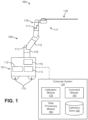
- FIG. 1 illustrates a surgical robotic system 100 according to one embodiment.
- the surgical robotic system 100 includes a base 101 coupled to one or more robotic arms, e.g., robotic arm 102.
- the base 101 is communicatively coupled to a command console, which is further described with reference to FIG. 2 in Section II. Command Console.
- the base 101 can be positioned such that the robotic arm 102 has access to perform a surgical procedure on a patient, while a user such as a physician may control the surgical robotic system 100 from the comfort of the command console.
- the base 101 may be coupled to a surgical operating table or bed for supporting the patient.
- the base 101 may include subsystems such as control electronics, pneumatics, power sources, optical sources, and the like.
- the robotic arm 102 includes multiple arm segments 110 coupled at joints 111, which provides the robotic arm 102 multiple degrees of freedom, e.g., seven degrees of freedom corresponding to seven arm segments.
- the base 101 may contain a source of power 112, pneumatic pressure 113, and control and sensor electronics 114-including components such as a central processing unit, data bus, control circuitry, and memory-and related actuators such as motors to move the robotic arm 102.
- the electronics 114 in the base 101 may also process and transmit control signals communicated from the command console.
- the base 101 includes wheels 115 to transport the surgical robotic system 100.
- Mobility of the surgical robotic system 100 helps accommodate space constraints in a surgical operating room as well as facilitate appropriate positioning and movement of surgical equipment. Further, the mobility allows the robotic arms 102 to be configured such that the robotic arms 102 do not interfere with the patient, physician, anesthesiologist, or any other equipment. During procedures, a user may control the robotic arms 102 using control devices such as the command console.
- the robotic arm 102 includes set up joints that use a combination of brakes and counter-balances to maintain a position of the robotic arm 102.
- the counter-balances may include gas springs or coil springs.
- the brakes e.g., fail safe brakes, may be include mechanical and/or electrical components.
- the robotic arms 102 may be gravity-assisted passive support type robotic arms.
- Each robotic arm 102 may be coupled to an instrument device manipulator (IDM) 117 using a mechanism changer interface (MCI) 116.
- the IDM 117 can be removed and replaced with a different type of IDM, for example, a first type of IDM manipulates an endoscope, while a second type of IDM manipulates a laparoscope.
- the MCI 116 includes connectors to transfer pneumatic pressure, electrical power, electrical signals, and optical signals from the robotic arm 102 to the IDM 117.
- the MCI 116 can be a set screw or base plate connector.
- the IDM 117 manipulates surgical instruments such as the endoscope 118 using techniques including direct drive, harmonic drive, geared drives, belts and pulleys, magnetic drives, and the like.
- the MCI 116 is interchangeable based on the type of IDM 117 and can be customized for a certain type of surgical procedure.
- the robotic 102 arm can include a joint level torque sensing and a wrist at a distal end, such as the KUKA AG ® LBR5 robotic arm.
- the endoscope 118 is a tubular and flexible surgical instrument that is inserted into the anatomy of a patient to capture images of the anatomy (e.g., body tissue).
- the endoscope 118 includes one or more imaging devices (e.g., cameras or sensors) that capture the images.
- the imaging devices may include one or more optical components such as an optical fiber, fiber array, or lens. The optical components move along with the tip of the endoscope 118 such that movement of the tip of the endoscope 118 results in changes to the images captured by the imaging devices.
- the endoscope 118 is further described with reference to FIGS. 3A-I in Section III. Endoscope.
- Robotic arms 102 of the surgical robotic system 100 manipulate the endoscope 118 using elongate movement members.
- the elongate movement members may include pull wires, also referred to as pull or push wires, cables, fibers, or flexible shafts.
- the robotic arms 102 actuate multiple pull wires coupled to the endoscope 118 to deflect the tip of the endoscope 118.
- the pull wires may include both metallic and non-metallic materials such as stainless steel, Kevlar, tungsten, carbon fiber, and the like.
- the endoscope 118 may exhibit unideal behavior in response to forces applied by the elongate movement members. The unideal behavior may be due to imperfections or variations in stiffness and compressibility of the endoscope 118, as well as variability in slack or stiffness between different elongate movement members.
- the surgical robotic system 100 includes a computer system 120, for example, a computer processor.
- the computer system 120 includes a calibration module 130, calibration store 140, command module 150, and data processing module 160.
- the data processing module 160 can process calibration data collected by the surgical robotic system 100.
- the calibration module 130 can characterize the unideal behavior of the endoscope 118 using gain values based on the calibration data.
- the computer system 120 and its modules are further described in Section VII: Calibration Process Flows.
- the surgical robotic system 100 can more accurately control an endoscope 118 by determining accurate values of the gain values.
- some or all functionality of the computer system 120 is performed outside the surgical robotic system 100, for example, on another computer system or server communicatively coupled to the surgical robotic system 100.
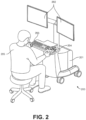
- FIG. 2 illustrates a command console 200 for a surgical robotic system 100 according to one embodiment.
- the command console 200 includes a console base 201, display modules 202, e.g., monitors, and control modules, e.g., a keyboard 203 and joystick 204.
- one or more of the command module 200 functionality may be integrated into a base 101 of the surgical robotic system 100 or another system communicatively coupled to the surgical robotic system 100.
- a user 205 e.g., a physician, remotely controls the surgical robotic system 100 from an ergonomic position using the command console 200.
- the console base 201 may include a central processing unit, a memory unit, a data bus, and associated data communication ports that are responsible for interpreting and processing signals such as camera imagery and tracking sensor data, e.g., from the endoscope 118 shown in FIG. 1 . In some embodiments, both the console base 201 and the base 101 perform signal processing for load-balancing.
- the console base 201 may also process commands and instructions provided by the user 205 through the control modules 203 and 204.
- the control modules may include other devices, for example, computer mice, trackpads, trackballs, control pads, video game controllers, and sensors (e.g., motion sensors or cameras) that capture hand gestures and finger gestures.
- the user 205 can control a surgical instrument such as the endoscope 118 using the command console 200 in a velocity mode or position control mode.
- velocity mode the user 205 directly controls pitch and yaw motion of a distal end of the endoscope 118 based on direct manual control using the control modules.
- movement on the joystick 204 may be mapped to yaw and pitch movement in the distal end of the endoscope 118.
- the joystick 204 can provide haptic feedback to the user 205.
- the joystick 204 vibrates to indicate that the endoscope 118 cannot further translate or rotate in a certain direction.
- the command console 200 can also provide visual feedback (e.g., pop-up messages) and/or audio feedback (e.g., beeping) to indicate that the endoscope 118 has reached maximum translation or rotation.
- the command console 200 uses a three-dimensional (3D) map of a patient and pre-determined computer models of the patient to control a surgical instrument, e.g., the endoscope 118.
- the command console 200 provides control signals to robotic arms 102 of the surgical robotic system 100 to manipulate the endoscope 118 to a target location. Due to the reliance on the 3D map, position control mode requires accurate mapping of the anatomy of the patient.
- users 205 can manually manipulate robotic arms 102 of the surgical robotic system 100 without using the command console 200.
- the users 205 may move the robotic arms 102, endoscopes 118, and other surgical equipment to access a patient.
- the surgical robotic system 100 may rely on force feedback and inertia control from the users 205 to determine appropriate configuration of the robotic arms 102 and equipment.
- the display modules 202 may include electronic monitors, virtual reality viewing devices, e.g., goggles or glasses, and/or other means of display devices.
- the display modules 202 are integrated with the control modules, for example, as a tablet device with a touchscreen.
- the user 205 can both view data and input commands to the surgical robotic system 100 using the integrated display modules 202 and control modules.
- the display modules 202 can display 3D images using a stereoscopic device, e.g., a visor or goggle.
- the 3D images provide an "endo view” (i.e., endoscopic view), which is a computer 3D model illustrating the anatomy of a patient.
- the "endo view” provides a virtual environment of the patient's interior and an expected location of an endoscope 118 inside the patient.
- a user 205 compares the "endo view” model to actual images captured by a camera to help mentally orient and confirm that the endoscope 118 is in the correct-or approximately correct-location within the patient.
- the "endo view” provides information about anatomical structures, e.g., the shape of an intestine or colon of the patient, around the distal end of the endoscope 118.
- the display modules 202 can simultaneously display the 3D model and computerized tomography (CT) scans of the anatomy the around distal end of the endoscope 118. Further, the display modules 202 may overlay pre-determined optimal navigation paths of the endoscope 118 on the 3D model and CT scans.
- CT computerized tomography
- a model of the endoscope 118 is displayed with the 3D models to help indicate a status of a surgical procedure.
- the CT scans identify a lesion in the anatomy where a biopsy may be necessary.
- the display modules 202 may show a reference image captured by the endoscope 118 corresponding to the current location of the endoscope 118.
- the display modules 202 may automatically display different views of the model of the endoscope 118 depending on user settings and a particular surgical procedure. For example, the display modules 202 show an overhead fluoroscopic view of the endoscope 118 during a navigation step as the endoscope 118 approaches an operative region of a patient.
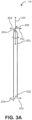
- FIG. 3A illustrates multiple degrees of motion of an endoscope 118 according to one embodiment.
- the endoscope 118 is an embodiment of the endoscope 118 shown in FIG. 1 .
- the tip 301 of the endoscope 118 is oriented with zero deflection relative to a longitudinal axis 306 (also referred to as a roll axis 306).
- a surgical robotic system 100 deflects the tip 301 on a positive yaw axis 302, negative yaw axis 303, positive pitch axis 304, negative pitch axis 305, or roll axis 306.
- the tip 301 or body 310 of the endoscope 118 may be elongated or translated in the longitudinal axis 306, x-axis 308, or y-axis 309.
- FIG. 3B is a top view of an endoscope 118 including sheath and leader components according to one embodiment.
- the endoscope 118 includes a leader 315 tubular component nested or partially nested inside and longitudinally-aligned with a sheath 311 tubular component.
- the sheath 311 includes a proximal sheath section 312 and distal sheath section 313.
- the leader 315 has a smaller outer diameter than the sheath 311 and includes a proximal leader section 316 and distal leader section 317.
- the sheath base 314 and the leader base 318 actuate the distal sheath section 313 and the distal leader section 317, respectively, for example, based on control signals from a user of a surgical robotic system 100.
- the sheath base 314 and the leader base 318 are, e.g., part of the IDM 117 shown in FIG. 1 .
- the construction, composition, capabilities, and use of distal leader section 317, which may also be referred to as a flexure section, are disclosed in U.S. Patent Application No. 14/201,610, filed March 7, 2014 , and U.S. Patent Application No. 14/479,095, filed September 5, 2014 .
- Both the sheath base 314 and the leader base 318 include drive mechanisms (e.g., the independent drive mechanism further described with reference to FIG. 4A-D in Section 111. D. Instrument Device Manipulator) to control pull wires coupled to the sheath 311 and leader 315.
- the sheath base 314 generates tensile loads on pull wires coupled to the sheath 311 to deflect the distal sheath section 313.
- the leader base 318 generates tensile loads on pull wires coupled to the leader 315 to deflect the distal leader section 317.
- Both the sheath base 314 and leader base 318 may also include couplings for the routing of pneumatic pressure, electrical power, electrical signals, or optical signals from IDMs to the sheath 311 and leader 314, respectively.
- a pull wire may include a steel coil pipe along the length of the pull wire within the sheath 311 or the leader 315, which transfers axial compression back to the origin of the load, e.g., the sheath base 314 or the leader base 318, respectively.
- the endoscope 118 can navigate the anatomy of a patient with ease due to the multiple degrees of freedom provided by pull wires coupled to the sheath 311 and the leader 315.
- pull wires coupled to the sheath 311 and the leader 315.
- four or more pull wires may be used in either the sheath 311 and/or the leader 315, providing eight or more degrees of freedom.
- up to three pull wires may be used, providing up to six degrees of freedom.
- the sheath 311 and leader 315 may be rotated up to 360 degrees along a longitudinal axis 306, providing more degrees of motion. The combination of rotational angles and multiple degrees of freedom provides a user of the surgical robotic system 100 with a user friendly and instinctive control of the endoscope 118.
- FIG. 3C is a cross sectional side view of the sheath 311 of the endoscope 118 according to one embodiment.
- the sheath 311 includes a lumen 323 sized to accommodate a tubular component such as the leader 315 shown in FIG. 3B .
- the sheath 311 includes walls 324 with pull wires 325 and 326 running through conduits 327 and 328 inside the length of walls 324.
- the conduits include a helix section 330 and a distal non-helix section 329.
- Appropriate tensioning of pull wire 325 may compress the distal end 320 in the positive y-axis direction, while minimizing bending of the helix section 330.
- appropriate tensioning of pull wire 326 may compress distal end 320 in the negative y-axis direction.
- the lumen 323 is not concentric with the sheath 311.
- Pull wires 325 and 326 do not necessarily run straight through the length of sheath 311. Rather, the pull wires 325 and 326 spiral around sheath 311 along helix section 330 and run longitudinally straight (i.e., approximately parallel to the longitudinal axis 306) along the distal non-helix section 329 and any other non-helix section of the sheath 311.
- the helix section 330 may start and end anywhere along the length of the sheath 311. Further, the length and pitch of helix section 330 may be determined based on desired properties of sheath 311, e.g., flexibility of the sheath 311 and friction in the helix section 330.
- pull wires 325 and 326 are positioned at 180 degrees relative to each other in FIG. 3C , it should be noted that pull wires of the sheath 311 may be positioned at different angles. For example, three pull wires of a sheath may each be positioned at 120 degrees relative to each other. In some embodiments, the pull wires are not equally spaced relative to each other, i.e., without a constant angle offset.
- FIG. 3D is an isometric view of a helix section 330 of the sheath 311 of the endoscope 118 according to one embodiment.
- FIG. 3D shows only one pull wire 325 for the purpose of distinguishing between the distal non-helix section 329 and the helix section 330.
- the helix section 330 has a variable pitch
- FIG. 3E is another isometric view of a helix section 330 of a sheath 311 of an endoscope 118 according to one embodiment.
- FIG. 3E shows four pull wires 325, 326, 351, and 352 extending along the distal non-helix section 329 and the variable pitch helix section 330.
- Helix sections 330 in the sheath 311 and leader 315 of the endoscope 118 help a surgical robotic system 100 and/or a user navigate the endoscope 118 through non-linear pathways in the anatomy of a patient, e.g., intestines or the colon.
- tensioning the pull wires to manipulate the distal section generated the unwanted bending and torqueing along a length of the endoscope, which may be referred to as muscling and curve alignment, respectively.
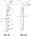
- FIG. 3F is a side view of the sheath 311 of the endoscope 118 with a helix section 330 according to one embodiment.
- FIGS. 3F-G illustrate how the helix section 330 helps substantially mitigate muscling and curve alignment. Since the pull wire 325 is spiraled around the length of helix section 330, the pull wire 325 radially and symmetrically distributes a compressive load 335 in multiple directions around the longitudinal axis 306. Further, bending moments imposed on the endoscope 118 are also symmetrically distributed around the longitudinal axis 306, which counterbalances and offsets opposing compressive forces and tensile forces. The distribution of the bending moments results in minimal net bending and rotational forces, creating a low potential energy state of the endoscope 118, and thus eliminating or substantially mitigating muscling and curve alignment.
- the pitch of the helix section 330 can affect the friction and the stiffness of the helix section 330.
- the helix section 330 may be shorter to allow for a longer distal non-helix section 329, resulting in less friction and/or stiffness of the helix section 330.
- FIG. 3G is another view of the sheath 311 of the endoscope 118 shown in FIG. 3F according to one embodiment. Compared to the distal non-helix section 329 shown in FIG. 3F , the distal non-helix section 329 shown in FIG. 3G is deflected at a greater angle.
- FIG. 3H is a cross sectional side view of the leader 315 of the endoscope 118 according to one embodiment.
- the leader 315 includes at least one working channel 343 and pull wires 344 and 345 running through conduits 341 and 342, respectively, along the length of the walls 348.
- the pull wires 344 and 345 and conduits 341 and 342 are substantially the same as the pull wires 325 and 326 and the conduits 327 and 328 in FIG. 3C , respectively.
- the pull wires 344 and 345 may have a helix section that helps mitigate muscling and curve alignment of the leader 315, similar to the sheath 311 as previously described.
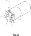
- FIG. 3I is a cross sectional isometric view of a distal tip of the leader 315 of the endoscope 118 shown in FIG. 3H according to one embodiment.
- the leader 315 includes an imaging device 349 (e.g., charge-coupled device (CCD) or complementary metal-oxide semiconductor (CMOS) camera, imaging fiber bundle, etc.), light sources 350 (e.g., light-emitting diode (LED), optic fiber, etc.), at least two pull wires 344 and 345, and at least one working channel 343 for other components.
- an imaging device 349 e.g., charge-coupled device (CCD) or complementary metal-oxide semiconductor (CMOS) camera, imaging fiber bundle, etc.
- light sources 350 e.g., light-emitting diode (LED), optic fiber, etc.
- at least two pull wires 344 and 345 e.g., light-emitting diode (LED), optic fiber, etc.
- the leader 315 includes a pocket hole to accommodate insertion of a component into a working channel 343. As shown in FIG. 31 , the pull wires 344 and 345 are not concentric with the an imaging device 349 or the working channel 343.
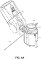
- FIG. 4A is an isometric view of an instrument device manipulator 117 of the surgical robotic system 100 according to one embodiment.
- the robotic arm 102 is coupled to the IDM 117 via an articulating interface 401.
- the IDM 117 is coupled to the endoscope 118.
- the articulating interface 401 may transfer pneumatic pressure, power signals, control signals, and feedback signals to and from the robotic arm 102 and the IDM 117.
- the IDM 117 may include a gear head, motor, rotary encoder, power circuits, and control circuits.
- a tool base 403 for receiving control signals from the IDM 117 is coupled to the proximal end of the endoscope 118. Based on the control signals, the IDM 117 manipulates the endoscope 118 by actuating output shafts, which are further described below with reference to FIG. 4B .
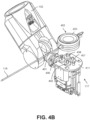
- FIG. 4B is an exploded isometric view of the instrument device manipulator shown in FIG. 4A according to one embodiment.
- the endoscopic 118 has been removed from the IDM 117 to reveal the output shafts 405, 406, 407, and 408.
- FIG. 4C is an isometric view of an independent drive mechanism of the instrument device manipulator 117 shown in FIG. 4A according to one embodiment.
- the independent drive mechanism can tighten or loosen the pull wires 421, 422, 423, and 424 (e.g., independently from each other) of an endoscope by rotating the output shafts 405, 406, 407, and 408 of the IDM 117, respectively.
- the output shafts 405, 406, 407, and 408 transfer force down pull wires 421, 422, 423, and 424, respectively, through angular motion
- the pull wires 421, 422, 423, and 424 transfer force back to the output shafts.
- the IDM 117 and/or the surgical robotic system 100 can measure the transferred force using a sensor, e.g., a strain gauge further described below.
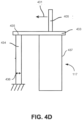
- FIG. 4D illustrates a conceptual diagram that shows how forces may be measured by a strain gauge 434 of the independent drive mechanism shown in FIG. 4C according to one embodiment.
- a force 431 may directed away from the output shaft 405 coupled to the motor mount 433 of the motor 437. Accordingly, the force 431 results in horizontal displacement of the motor mount 433. Further, the strain gauge 434 horizontally coupled to the motor mount 433 experiences strain in the direction of the force 431. The strain may be measured as a ratio of the horizontal displacement of the tip 435 of strain gauge 434 to the overall horizontal width 436 of the strain gauge 434.
- the IDM 117 includes additional sensors, e.g., inclinometers or accelerometers, to determine an orientation of the IDM 117. Based on measurements from the additional sensors and/or the strain gauge 434, the surgical robotic system 100 can calibrate readings from the strain gauge 434 to account for gravitational load effects. For example, if the IDM 117 is oriented on a horizontal side of the IDM 117, the weight of certain components of the IDM 117 may cause a strain on the motor mount 433. Accordingly, without accounting for gravitational load effects, the strain gauge 434 may measure strain that did not result from strain on the output shafts.
- additional sensors e.g., inclinometers or accelerometers
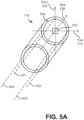
- FIG. 5A illustrates pull wires inside the endoscope 118 according to one embodiment.
- the endoscope 118 may include a different number of pull wires depending upon the construction of the endoscope, but for sake of example the following description assumes a construction where the endoscope 118 includes the four pull wires 421, 422, 423, and 423 each a corresponding to a direction of movement along the yaw 510 and pitch 520 axis.
- pulling the pull wires 421, 422, 423, and 423 moves the endoscope 118 in the positive pitch direction, positive yaw direction, negative pitch direction, and negative yaw direction, respectively.
- the pull wires may not necessarily be aligned along these axes, the axes above are arbitrarily chosen for convenience of explanation.
- a pull wire may be aligned with (e.g., intersect) the point 540 in the endoscope 118.
- translating the pull wire would cause the endoscope 118 to move in both the yaw 510 and pitch 520 directions.
- the pull wires are approximately parallel with the roll 530 axis.
- the endoscope 118 may include one or more spatial sensors 550 coupled toward the distal tip of the endoscope 118.
- the spatial sensors 550 can be, for example, an electromagnetic (EM) sensor, accelerometer, gyroscope, fiducial marker, and/or other types of sensors.
- the spatial sensor 550 is a shape sensing optical fiber embedded inside the endoscope 118 and running along a length of the endoscope 118.
- the spatial sensors 550 may provide spatial data indicating a position and/or orientation of the endoscope 118, e.g., in real-time. Spatial data may also be used as calibration data to assist in calibration of the endoscope 118.
- translating pull wires of the endoscope moves the endoscope exactly to a target position or orientation, e.g., bend the tip of the endoscope 90 degrees in the positive pitch direction.
- a target position or orientation e.g., bend the tip of the endoscope 90 degrees in the positive pitch direction.
- the target motion does not necessarily match the actual motion of the endoscope, and the endoscope may exhibit nonlinear behavior.
- Imperfections may arise for a variety of reasons, examples of which may be the result of defects in manufacturing (e.g., a pull wire is not properly aligned with an axis of motion), variances in the pull wires (e.g., a pull wire is more stiff, or different in length, than another pull wire), or variances in the endoscope material (e.g., the pitch direction bends more easily than the yaw direction).
- FIGS. 5B-5D illustrate three views of an endoscope 118 in a resting position.
- FIGS. 5E-G illustrate the same three views after the endoscope 118 has been moved to a deflected position in response to a command to articulate to a target deflection of 90 degrees in the positive pitch 520 direction. As shown in FIGS. 5E-G , the actual deflection of the endoscope 118 exhibits an unideal offset in the positive pitch 520 direction.
- FIG. 5B shows a back view of the endoscope 118 in a resting position according to one embodiment.
- a viewer is looking down from the proximal end of the endoscope, where the opposite distal end would be inserted into a body of a patient.
- the cross section of the endoscope 118 is aligned to the origin of the yaw 510 and pitch 520 axis.
- the endoscope 118 is parallel to the roll 530 axis, and a spatial sensor 550 is coupled toward the tip of the endoscope 118.
- FIG. 5C shows a top view of the endoscope 118 shown in FIG. 5B according to one embodiment.
- FIG. 5D shows a side view of the endoscope 118 shown in FIG. 5B according to one embodiment.
- FIG. 5E shows a back view of the endoscope 118 shown in FIG. 5B in the deflected position according to one embodiment.
- FIG. 5F shows a top view of the endoscope 118 shown in FIG. 5E according to one embodiment.
- FIG. 5G shows a side view of the endoscope 118 shown in FIG. 5E according to one embodiment.
- the dotted outline of the endoscope 118 indicates the target deflected position that the endoscope should have moved to in response to the command, e.g., the tip of the endoscope 118 is supposed deflect 90 degrees in the positive pitch direction to become parallel to the pitch 520 axis. However, the actual deflected position is short of a 90 degree deflection, and thus exhibits the unideal offset in the positive pitch 520 direction.
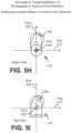
- FIG. 5H shows a back view of the endoscope 118 shown in FIG. 5B in a deflected position with an additional unideal offset according to one embodiment.
- the endoscope shown in FIG. 5H exhibits an additional unideal offset in the positive yaw 510 direction.
- the distal end (e.g., tip) of the endoscope 118 is "curved," in contrast to the distal end of the endoscope shown in FIG. 5F that is "straight.”
- the endoscope 118 shown in FIG. 5H has imperfections in two directions (positive pitch and yaw), however, in other embodiments, endoscopes can exhibit imperfections in any number of directions (e.g., negative pitch and yaw, as well as roll).
- FIG. 5I shows a top view of the endoscope 118 shown in FIG. 5H according to one embodiment.
- FIGS. 5J-5K illustrate two views of an endoscope 118 in a resting position.
- Four markers 560 are shown on the endoscope 118 for purposes of illustrating the alignment of the endoscope 118 relative to the yaw 510 and pitch 520 directions. In the resting position, each of the markers are aligned with the yaw 510 and pitch 520 axis.
- FIGS. 5L-M illustrate the same two views after the endoscope 118 has been moved to a deflected position in response to a command to articulate to a target deflection of 90 degrees in the positive pitch 520 direction.
- the actual deflection of the endoscope 118 exhibits an unideal offset in the roll 530 direction (and no other unideal offsets in this example).
- the dotted outline of the endoscope 118 indicates the target deflected position that the endoscope should have moved to in response to the command, e.g., the tip of the endoscope 118 is supposed deflect 90 degrees to become parallel to the pitch 520 axis.
- the actual deflected position has a deflection 90 degrees, but also has a rotation along the roll 530 axis.
- the four markers 560 are no longer aligned with the yaw 510 and pitch 520 axis.
- the distal end of the endoscope in FIG. 5L is "straight" and not “curved.”
- rotation of the proximal end of an endoscope is accompanied by corresponding rotation of the distal end of the endoscope (and vice versa).
- the rotations may be equal or different, e.g., a 10 degree roll offset of the proximal end causes a 20 degree roll offset of the distal end.
- FIG. 5M shows a side view of the endoscope shown in FIG. 5L according to one embodiment.
- FIGS. 5B-G illustrate an unideal offset in the positive pitch direction
- FIGS. 5H-I illustrate an unideal offset in the yaw direction in addition to in the positive pitch direction
- FIGS. 5J-M illustrate an unideal offset in the roll direction.
- endoscopes may exhibit unideal offsets in any number or combination of directions. The magnitude of the offsets may vary between different directions.
- FIG. 6A is a diagram of electromagnetic tracking system according to one embodiment.
- the spatial sensor 550 coupled to the tip of the endoscope 118 includes one or more EM sensors 550 that detect an electromagnetic field (EMF) generated by one or more EMF generators 600 in proximity to the endoscope 118.
- EMF electromagnetic field
- the strength of the detected EMF is a function of the position and/or orientation of the endoscope 118. If the endoscope 118 includes more than one EM sensor 550, for example, a first EM sensor is coupled to a leader tubular component and a second EM sensor is coupled to a sheath tubular component of the endoscope 118.
- One or more EMF generators 600 are located externally to a patient.
- the EMF generators 600 emit EM fields that are picked up by the EM sensor 550.
- EMF generators 600 and/or EM sensors 550 may be modulated in a number of different ways so that when their emitted/received fields are processed by the computer system 120 (or any computer system external to the surgical robotic system 100), the signals are separable.
- the computer system 120 can process multiple signals (sent and/or received) each as a separate input providing separate triangulation location regarding the location of the EM sensor/s 550, and by extension the position of the endoscope 118.
- multiple EMF generators 600 may be modulated in time or in frequency, and may use orthogonal modulations so that each signal is fully separable from each other signal (e.g., using signal processing techniques such as filtering and Fourier Transforms) despite possibly overlapping in time.
- the multiple EM sensors 550 and/or EMF generators 600 may be oriented relative to each other in Cartesian space at non-zero, non-orthogonal angles so that changes in orientation of the EM sensor/s 550 will result in at least one of the EM sensor/s 550 receiving at least some signal from the one or more EMF generators 600 at any instant in time.
- each EMF generator 600 may be, along any axis, offset at a small angle (e.g., 7 degrees) from each of two other EM generators 600 (and similarly with multiple EM sensors 550s). As many EMF generators or EM sensors as desired may be used in this configuration to assure accurate EM sensor position information along all three axes and, if desired, at multiple points along the endoscope 118.
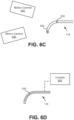
- FIG. 6B is a diagram of cameras in proximity to an endoscope 118 according to one embodiment.
- the cameras may include any type of optical cameras such as digital video cameras, stereo cameras, high-speed cameras, light field cameras, etc.
- a first camera 610 is parallel to a longitudinal axis of the endoscope 118.
- a second camera 620 is orthogonal to the first camera 610. Since the cameras each capture image frames showing the position and/or orientation of the endoscope in at least two-dimensions, aligning the two cameras orthogonal to each other enables the surgical robotic system 100 to receive information about the endoscope in at least three-dimensions (e.g., corresponding to the pitch, yaw, and roll axis).
- three or more cameras may be used to capture images of the endoscope 118.
- the data processing module 160 may implement object tracking image processing techniques using the captured image frames to determine the real-time 3D position of the endoscope 118.
- Example techniques include correlation-based matching methods, feature-based methods, and optical flow.
- FIG. 6C is a diagram of motion cameras in proximity to an endoscope 118 including fiducial markers according to one embodiment.
- the spatial sensors 550 coupled to toward the distal end of the endoscope 118 are fiducial markers.
- the motion cameras 630 and 640 capture image frames that track the position and movement of the fiducial markers. Though two fiducial markers and two motion cameras are shown in FIG. 6C , other embodiments may include any other number of fiducial markers coupled to the endoscope and/or motion cameras to track the fiducial markers.
- the motion cameras in FIG. 6C capture data describing the motion of the fiducial markers.
- the data processing module 160 requires less computational resources to process the motion camera data than to process data captured from other optical cameras without using fiducial markers.
- other optical cameras capture data describing the visual appearance (e.g., color and size) of the endoscope 118.
- the motion cameras may only need to capture the real-time coordinate position of each fiducial marker, which is sufficient for the data processing module 160 to use to determine overall movement of the endoscope 118 in different directions (e.g., pitch, yaw, and roll) in response to commands from the surgical robotic system 100.
- Camera based sensors may be more suitable for determining the position of an endoscope outside a body of a patient, while EM sensors may be more suitable for use cases where the endoscope is inside the body.
- image processing techniques using camera data provide more accurate or higher resolution position and motion data than EM sensor based techniques, e.g., because a user viewing the endoscope outside of the body can validate the results of image processing techniques.
- EM sensors have an advantage in that they can still detect EM fields generated by EMF generators even when the endoscope is located inside a patient.
- FIG. 6D is a diagram of an endoscope 118 with a shape sensing optical fiber according to one embodiment.
- the spatial sensor 550 is a shape sensing optical fiber embedded inside the endoscope 118.
- a console 650 positioned in proximity to the endoscope 118 is coupled to the shape sensing optical fiber.
- the console 650 transmits light through the shape sensing optical fiber and receives light reflected from the shape sensing optical fiber.
- the shape sensing optical fiber may include a segment of a fiber Bragg grating (FBG).
- the FBG reflects certain wavelengths of light, while transmitting other wavelengths.
- the console 650 generates reflection spectrum data based on the wavelengths of light reflected by the FBG.
- the data processing module 160 can analyze the reflection spectrum data to generate position and orientation data of the endoscope 118 in two or three dimensional space.
- the shape sensing optical fiber embedded inside also bends.
- the specific wavelengths of light reflected by the FBG changes based on the shape of the shape sensing optical fiber (e.g., a "straight" endoscope is in a different shape than a "curved" endoscope).
- the data processing module 160 can determine, for example, how many degrees the endoscope 118 has bent in one or more directions (e.g., in response to commands from the surgical robotic system 100) by identifying differences in the reflection spectrum data.
- the shape sensing optical fiber is suitable for data collection inside the body of the patient because no line-of-sight to the shape sensing optical fiber is required
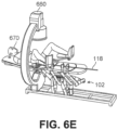
- FIG. 6E is a diagram of a fluoroscopic imaging system 660 in proximity to an endoscope 118 according to one embodiment.
- the endoscope 118 is inserted by robotic arms 102 into a patient 670 undergoing a surgical procedure.
- the fluoroscopic imaging system 660 is a C-arm that includes a generator, detector, and imaging system (not shown).
- the generator is coupled to the bottom end of the C-arm and faces upward toward the patient 670.
- the detector is coupled to the top end of the C-arm and faces downward toward the patient 670.
- the generator emits X-ray waves toward the patient 670.
- the X-ray waves penetrate the patient 670 and are received by the detector.
- the fluoroscopic imaging system 660 Based on the received X-ray waves, the fluoroscopic imaging system 660 generates the images of body parts or other objects inside the patient 670 such as the endoscope 118. In contrast to the optical cameras described in Section. V. B. Camera Sensors that capture images of the actual endoscope, the fluoroscopic imaging system 660 generates images that include representations of objects inside the patient 670, e.g., an outline of the shape of an endoscope based on the reflected X-rays. Thus, the data processing module 160 can use similar image processing techniques as previously described such as optical flow to determine the position and motion of the endoscope, e.g., in response to commands from the surgical robotic system 100.
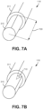
- FIG. 7A shows a length 700 of a leader 315 of an endoscope 118 extended outside of a sheath 311 of the endoscope 118 according to one embodiment.
- the flexibility of the distal end of the leader 315 increases because the length 700 is not as significantly enclosed by the sheath 311.
- the portion of the leader 315 radially enclosed by the sheath 311 is less flexible because the material of the sheath 311 provides more rigidity.
- the surgical robotic system 100 needs to provide commands to move the endoscope that account for the extension.
- the distal end of the endoscope may become heavier (and/or more flexible) as the extension increases because there is more length of the leader outside of the sheath.
- the surgical robotic system 100 may need to provide a command that translates pull wires of the endoscope to a greater degree relative to a command to move an endoscope with a smaller length of extension.
- FIG. 7B shows a relative roll angle 710 of the leader 315 of the endoscope 118 relative to the sheath 311 of the endoscope 118 according to one embodiment.
- the leader 315 and/or the sheath 311 may be more flexible in certain directions compared to other directions, e.g., due to variances in the material of the endoscope 118.
- the flexibility of the endoscope 118 may change in a certain direction.
- the surgical robotic system 100 may also need to account for the relative roll angle when providing commands to move the endoscope. For example, a command to bend the endoscope 90 degrees may result in an actual bend of 80 degrees when the relative roll angle is 5 degrees, but may result in an actual bend of 100 degrees when the relative roll angle is -5 degrees.
- the surgical robotic system 100 performs a calibration process to determine gain values that compensate for imperfections of an endoscope's behavior.
- the surgical robotics system 100 moves the endoscope to one or more target positions (or angles) by translating one or more pull wires according to one or more commands.
- the surgical robotics system 100 receives spatial data indicating actual positions and orientations of the endoscope achieved in response to the commands, where the actual positions may be different than the target positions due to the endoscope's imperfections.
- the surgical robotics system 100 determines the gain values based on the commands, the target positions desired to be achieved, and the actual positions achieved.
- the surgical robotics system 100 can perform such a calibration process before a surgical procedure, for example, on a manufacturing line for quality assurance, or in a laboratory or clinical setting. Additionally, the surgical robotics system 100 can perform such a calibration process while performing a surgical procedure on a patient.
- the material of a particular endoscope may be stiffer than expected.
- the spatial data indicates that the endoscope deflected to an actual position of 30 degrees in the pitch direction, whereas the target position was 60 degrees.
- the surgical robotics system 100 determines that the corresponding gain value for the endoscope is the decimal value of 2.0 because the target position is two times the value of the actual position.
- the gain value may be represented using other formats, e.g., a percentage, an integer, in unit of degrees, etc.
- Gain values can be associated with a particular pull wire, endoscope, direction of motion (e.g., positive pitch direction, negative yaw direction, or roll direction), and/or other types of factors.
- direction of motion e.g., positive pitch direction, negative yaw direction, or roll direction
- the example described above is a trivial scenario that assumes a constant gain value of 2.0 for all conditions of the endoscope.
- calibrating endoscopes is a more complex problem because the gain values depend on a plethora of factors, either independently or in combination.
- the gain value may be 2.0 in the positive pitch direction, 3.0 in the negative pitch direction, 1.5 in the positive yaw direction, etc.
- the gain value may be 2.0 in the positive pitch direction for a first pull wire but 2.2 for a second pull wire in the same endoscope.
- the gain value may be 2.0 for the first pull wire of a first endoscope, but 2.5 for the first pull wire of a second endoscope.
- the calibration module 130 receives a length of a leader of the endoscope extended outside of (or radially enclosed by) a sheath of the endoscope and/or a relative roll angle of the leader relative to the sheath.
- the calibration module 130 determines the gain values further based on the length and/or the relative roll angle. Gain values for a certain length or relative roll angle may differ from gain values for another length or relative roll angle because the endoscope may be more flexible in a particular direction or segment of the endoscope.
- the endoscope (e.g., the leader and/or the sheath) includes multiple segments each having a different level of stiffness.
- the calibration module 130 receives a Young's modulus of at least one of the segments and determines the gain values further based on the Young's modulus.
- a complete calibration process involves several sub-calibration processes.
- the surgical robotic system 100 provides a command to move an endoscope to a target position in a first direction.
- the calibration module 130 receives calibration data indicating an actual position of the endoscope, which may differ from the target position.
- the surgical robotic system 100 relaxes the endoscope back to a resting position, and repeats the data collection process for a number of other directions
- the surgical robotic system 100 can also provide commands to extend the leader to a greater lengths outside of the sheath, and repeat the calibration data collection process for a number of different lengths of extension.
- the surgical robotic system 100 can provide commands to rotate the leader to a relative roll angle relative to the sheath, and repeat the calibration data collection process for a number of different relative roll angles.
- the calibration module 130 determines gain values based on an aggregate calibration dataset from each of the sub-calibration processes. As evident by the number of potential combination of factors to consider during calibration, the calibration process may become a more complex process with many nested loops of different tests. Thus, it is advantageous to automate the calibration using the surgical robotic system 100, e.g., to help keep track of all the factors that need to be tested, reduce the chance for calibration errors or oversights, and eliminate the need for a user to manually conduct rote tasks for each test.
- the calibration module 130 stores the calibration data and associated gain values with one or more other factors (e.g., information about the corresponding command to move the endoscope, a direction of movement, an identifier of a certain pull wire, a length and/or relative roll angle of the leader relative to the sheath, or a unique identifier of the endoscope) in the calibration store 140.
- the calibration module 130 may upload the calibration data, gain values, and/or factors to a global calibration database including information from multiple endoscopes.
- the surgical robotic system 100 may use one or more types of models to generate commands to move an endoscope appropriately based on the calibration data.
- the command module 150 generates a command for each pull wire of an endoscope based on parameters of one of the models, where the parameters and associated gain values are determined based on the calibration data.
- the parameters may be the same as the gain values for some models, while for other models, the surgical robotic system 100 may determine the gain values based on the parameters.
- the models may be associated with the leader, sheath, or both the leader and sheath of an endoscope. Embodiments of models that are associated with both the leader and sheath account for parameters describing interaction between the leader and sheath, e.g., the length of extension and relative roll angle of the leader relative to the sheath.
- the calibration module 130 uses an empirical model implemented with a matrix of gain values.
- the gain values are empirically determined by solving a set of linear equations based on calibration data from previously completed calibration processes.
- the calibration module 130 can multiply a vector representing the input command (e.g., including a target translation for each pull wire of an endoscope as well as extension and relative roll values) by the matrix of gain values can generate an output vector representing an adjusted command (e.g., including modified translations for one or more of the pull wires).
- the empirical model gain values may compensate for pull-wire specific compression or expansion based on bending of the endoscope. In particular, the distance that a certain pull wire travels inside the endoscope may shrink or lengthen based on the curvature of the endoscope.
- the empirical model accounts for the dependency between wires in opposing directions. For example, a first wire corresponds to the positive pitch direction and a second wire corresponds to the negative pitch direction. Providing slack on the first wire while pulling on the second wire both contribute to the same motion of bending the endoscope in the negative pitch direction.
- the calibration module 130 uses a physics based model to determine the effective physical properties of the endoscope as it bends.
- the physics based model has the potential to more fully capture the behavior of the endoscope.
- a trivial model may assume that a bent endoscope bends uniformly throughout a particular length of the endoscope according to a given bending stiffness in that particular length and remains straight throughout the rest of the length of the endoscope
- the physics based model may decompose the leader and sheath of the endoscope into individual segments that each have an associated bending stiffness.
- the physics based model also considers the stiffness of the pull wires and the effect of the sheath and leader interaction (e.g., extension length and relative roll angle) on the stiffness of any particular segment.
- the computer system 120 may use inverse solid mechanics to translate commands to move the endoscope (e.g., indicating an angle to bend in pitch and/or yaw directions) into distances that the surgical robotic system 100 should translate one or more pull wires to achieve the desired motion. Further, by using the physics based model, the robotic system 100 may move one or more IDMs to compensate for any unwanted motion of the endoscope's distal tip as a result of axial deformations coupled to bending motions.
- the calibration module 130 uses a model-less inversion process to generate commands to move the endoscope.
- the calibration module 130 implements a lookup table that does not require the use of gain values and/or parameters. Instead, the lookup table maps previously recorded input values (e.g., commands to move the endoscope in pitch and yaw directions) to output values (e.g., translation for each pull wire of the endoscope) based on calibration data.
- the lookup table may interpolate (e.g., solved via Delaunay triangulation or other multidimensional triangulations techniques) or extrapolate between data points if the exact input-to-output mapping is not known, e.g., bending 42 degrees can be interpolated using data points for 40 degrees and 45 degrees.
- the calibration module 130 can minimize the size of the data set of mappings by using techniques such as Taylor decomposition or approximating the data set using a Fourier representation.
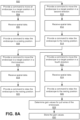
- FIG. 8A is a flowchart of a process 800 for automated calibration of an endoscope according to one embodiment.
- the process 800 may include different or additional steps than those described in conjunction with FIG. 8A in some embodiments, or perform steps in different orders than the order described in conjunction with FIG. 8A .
- the process 800 is particular for calibrating an embodiment of an endoscope including four pull wires, e.g., each separated by 90 degrees and corresponding to the, positive or negative, pitch or yaw directions.
- the process 800 can be generalized to any number of pull wires, and further discussed with reference to FIG. 8B . Since the computer system 120 is capable of automating the process 800, a user does not have to manually perform a calibration procedure to use the surgical robotic system 100. Automated calibration is advantageous, e.g., because the process reduces the time required to calibrate an endoscope.
- the command module 150 provides 804 a command to move an endoscope to a target position in a first direction.
- the calibration module 130 receives 806 spatial data indicating an actual position and orientation of the endoscope, which moved in response to the command.
- the spatial data can be received from spatial sensors (e.g., coupled to the endoscope or positioned in proximity to the endoscope) such as accelerometers, gyroscopes, fiducial markers, fiber optic cables, cameras, or an imaging system, as previously described in Section V. Spatial Sensors.
- the spatial data describes the position and/or orientation of the endoscope-or a portion of the endoscope-in one or more directions of movement.
- the command module 150 provides 808 a command to relax the endoscope to a resting position.
- the command module 150 provides 810 a command to move the endoscope to the target position in a second direction.
- the calibration module 130 receives 812 spatial data.
- the command module 150 provides 814 a command to relax the endoscope to the resting position.
- the command module 150 provides 816 a command to move the endoscope to the target position in a third direction.
- the calibration module 130 receives 818 spatial data.
- the command module 150 provides 820 a command to relax the endoscope to the resting position.
- the command module 150 provides 822 a command to move the endoscope to the target position in a fourth direction.
- the calibration module 130 receives 824 spatial data.
- the command module 150 provides 826 a command to relax the endoscope to the resting position.
- the target position may remain constant for each of the four directions.
- the target position varies between different directions.
- the target position is 90 degrees for the first and third directions and 45 degrees for the second and fourth directions.
- the first, second, third, and fourth directions may be the positive pitch, positive yaw, negative pitch, and negative yaw directions, in any particular order.
- the commands move the endoscope toward the target position simultaneously in two or more directions, e.g., 60 degrees in both the positive pitch and positive yaw directions.
- process 800 involves four directions, in other embodiments, the computer system 120 can repeat the steps 804 through 808 for any other number of directions (more or fewer).
- the calibration module 130 determines 828 gain values for pull wires of the endoscope based on the spatial data for one or more of the directions.
- the calibration module 130 may determine a gain value associated with each pull wire. At least one of the gain values may have a value different from unity. A unity gain value indicates that the corresponding pull wire exhibits ideal behavior, e.g., the actual motion of the endoscope matches the target motion based on translation of the corresponding pull wire.
- the calibration module 130 retrieves default gain values (e.g., determined in a previous calibration process) for the pull wires and determines the gain values further based on the default gain values.
- the calibration module 130 stores 830 the gain values in the calibration store 140.
- the endoscope may include a computer readable tangible medium, e.g., flash memory or a database, to store the gain values.
- the command module 150 provides a command to modify the length and/or relative roll angle of the leader relative to the sheath, and the surgical robotic system 100 repeats steps of the process 800 to determine gain values associated with the modified length and/or relative roll angle.
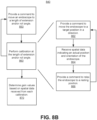
- FIG. 8B is a flowchart of a process 840 for automated calibration of an endoscope based on length of extension and relative roll angle according to one embodiment.
- the process 840 may include different or additional steps than those described in conjunction with FIG. 8B in some embodiments, or perform steps in different orders than the order described in conjunction with FIG. 8B .
- the process 840 is generalized to any number of directions, as well as any number of lengths of extension and relative roll angles of the leader relative to the sheath of an endoscope.
- an endoscope may include three pull wires offset from each other by 120 degrees, or in any other configuration with different offset angles (e.g., at the 11 o'clock, 2 o'clock, and 6 o'clock hand positions of a clock).
- the surgical robotic system 100 provides 850 a command to move an endoscope to a length or extension and/or relative roll angle.
- the surgical robotic system 100 performs 860 calibration at the length or extension and/or relative roll angle.
- the command module 150 provides 862 a command to move the endoscope to a target position in a direction.
- the calibration module 130 receives 864 spatial data indicating an actual position and orientation of the endoscope.
- the command module 150 provides 866 a command to relax the endoscope to a resting position.
- the surgical robotic system 100 repeats the steps 862-866 for each direction in a set of directions.
- the surgical robotic system 100 repeats the steps 850-860 for each length of extension and/or relative roll angle (or combination of lengths of extension and relative roll angles) in a set of different lengths of extension and/or relative roll angles.
- the calibration module 130 determines 870 gain values based on spatial data received from each calibration.
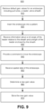
- FIG. 9 is a flowchart of a process 900 for intraoperative automated calibration of an endoscope to one embodiment.
- the process 900 may include different or additional steps than those described in conjunction with FIG. 9 in some embodiments, or perform steps in different orders than the order described in conjunction with FIG. 9 .
- the command console 200 may use the process 900 in the velocity mode or position control mode previously described in Section II. Command Console.
- the calibration module 130 retrieves 910 default gain values for an endoscope including pull wires, a leader, and a sheath. Each pull wire may be associated with one of the default gain values.
- the surgical robotic system 100 inserts 920 the endoscope into a patient undergoing a surgical procedure, e.g., ureteroscopy, percutaneous nephrolithotomy (PCNL), colonoscopy, fluoroscopy, prostatectomy, colectomy, cholecystectomy, inguinal hernia, and bronchoscopy.
- the calibration module 130 receives 930 information about a relative roll angle of the leader relative to the sheath and a length of the leader radially enclosed by the sheath.
- the information about the relative roll angle and the length may be based on previous commands provided to move the endoscope, a default relative roll angle and length value, or data generated by sensors (e.g., an accelerometer and gyroscope coupled to the endoscope).
- the command module 150 provides 940 a command to move the endoscope by translating at least one of the pull wires.
- the calibration module 130 receives 950 spatial data of the endoscope having been moved in response to the command.
- the spatial data is received from a fluoroscopic imaging system.
- the fluoroscopic imaging system can capture images of the endoscope inside the patient, which enables the surgical robotic system 100 to perform the process 900 during a surgical procedure.
- the calibration module 130 determines 960 a new gain value based on the spatial data, the corresponding default gain value, the length of extension, the relative roll angle, and/or the command.
- the calibration module 130 stores 970 the new gain value in the calibration store 140.
- the surgical robotic system 100 can generate additional commands based on new gain values determined by the process 900.
- the endoscope moves to an actual position of 80 degrees in response to a first command, where the target position is actually 90 degrees.
- the command module 150 generates a new command based on the new gain values and provides the new command to move the endoscope using the surgical robotic system 100. Since the new command compensates for the angle discrepancy (that is, 80 degrees is 10 degrees short of 90 degrees), the endoscope moves to an actual position of 90 degrees in response to the new command.
- any reference to "one embodiment” or “an embodiment” means that a particular element, feature, structure, or characteristic described in connection with the embodiment is included in at least one embodiment.
- the appearances of the phrase “in one embodiment” in various places in the specification are not necessarily all referring to the same embodiment.
- Coupled and “connected” along with their derivatives.
- some embodiments may be described using the term “coupled” to indicate that two or more elements are in direct physical or electrical contact.
- the term “coupled,” however, may also mean that two or more elements are not in direct contact with each other, but yet still co-operate or interact with each other.
- the embodiments are not limited in this context unless otherwise explicitly stated.
- the terms “ comprises,” “comprising,” “includes,” “including,” “has,” “having” or any other variation thereof, are intended to cover a non-exclusive inclusion.
- a process, method, article, or apparatus that comprises a list of elements is not necessarily limited to only those elements but may include other elements not expressly listed or inherent to such process, method, article, or apparatus.
- “or” refers to an inclusive or and not to an exclusive or. For example, a condition A or B is satisfied by any one of the following: A is true (or present) and B is false (or not present), A is false (or not present) and B is true (or present), and both A and B are true (or present).
- a software module is implemented with a computer program product including a computer-readable non-transitory medium containing computer program code, which can be executed by a computer processor for performing any or all of the steps, operations, or processes described.
- Embodiments of the invention may also relate to a product that is produced by a computing process described herein.
- a product may include information resulting from a computing process, where the information is stored on a non-transitory, tangible computer readable storage medium and may include any embodiment of a computer program product or other data combination described herein.
Applications Claiming Priority (2)
| Application Number | Priority Date | Filing Date | Title |
|---|---|---|---|
| US15/282,079 US9931025B1 (en) | 2016-09-30 | 2016-09-30 | Automated calibration of endoscopes with pull wires |
| PCT/US2017/054127 WO2018064394A1 (en) | 2016-09-30 | 2017-09-28 | Automated calibration of endoscopes with pull wires |
Publications (3)
| Publication Number | Publication Date |
|---|---|
| EP3518724A1 EP3518724A1 (en) | 2019-08-07 |
| EP3518724B1 true EP3518724B1 (en) | 2023-06-07 |
| EP3518724C0 EP3518724C0 (en) | 2023-06-07 |
Family
ID=60120148
Family Applications (1)
| Application Number | Title | Priority Date | Filing Date |
|---|---|---|---|
| EP17785088.0A Active EP3518724B1 (en) | 2016-09-30 | 2017-09-28 | Automated calibration of endoscopes with pull wires |
Country Status (7)
| Country | Link |
|---|---|
| US (4) | US9931025B1 (zh) |
| EP (1) | EP3518724B1 (zh) |
| JP (1) | JP7019683B2 (zh) |
| KR (1) | KR102297011B1 (zh) |
| CN (2) | CN108882837B (zh) |
| AU (1) | AU2017336790B2 (zh) |
| WO (1) | WO2018064394A1 (zh) |
Families Citing this family (291)
| Publication number | Priority date | Publication date | Assignee | Title |
|---|---|---|---|---|
| US8414505B1 (en) | 2001-02-15 | 2013-04-09 | Hansen Medical, Inc. | Catheter driver system |
| JP4755638B2 (ja) | 2004-03-05 | 2011-08-24 | ハンセン メディカル,インク. | ロボットガイドカテーテルシステム |
| EP1906858B1 (en) | 2005-07-01 | 2016-11-16 | Hansen Medical, Inc. | Robotic catheter system |
| US10893912B2 (en) | 2006-02-16 | 2021-01-19 | Globus Medical Inc. | Surgical tool systems and methods |
| US10653497B2 (en) | 2006-02-16 | 2020-05-19 | Globus Medical, Inc. | Surgical tool systems and methods |
| US10357184B2 (en) | 2012-06-21 | 2019-07-23 | Globus Medical, Inc. | Surgical tool systems and method |
| US9232959B2 (en) | 2007-01-02 | 2016-01-12 | Aquabeam, Llc | Multi fluid tissue resection methods and devices |
| EP2259742B1 (en) | 2008-03-06 | 2020-01-01 | AquaBeam LLC | Tissue ablation and cautery with optical energy carried in fluid stream |
| US9254123B2 (en) | 2009-04-29 | 2016-02-09 | Hansen Medical, Inc. | Flexible and steerable elongate instruments with shape control and support elements |
| US8672837B2 (en) | 2010-06-24 | 2014-03-18 | Hansen Medical, Inc. | Methods and devices for controlling a shapeable medical device |
| US20120071752A1 (en) | 2010-09-17 | 2012-03-22 | Sewell Christopher M | User interface and method for operating a robotic medical system |
| US20120191079A1 (en) | 2011-01-20 | 2012-07-26 | Hansen Medical, Inc. | System and method for endoluminal and translumenal therapy |
| US9308050B2 (en) | 2011-04-01 | 2016-04-12 | Ecole Polytechnique Federale De Lausanne (Epfl) | Robotic system and method for spinal and other surgeries |
| US20130030363A1 (en) | 2011-07-29 | 2013-01-31 | Hansen Medical, Inc. | Systems and methods utilizing shape sensing fibers |
| US20130303944A1 (en) | 2012-05-14 | 2013-11-14 | Intuitive Surgical Operations, Inc. | Off-axis electromagnetic sensor |
| US9452276B2 (en) | 2011-10-14 | 2016-09-27 | Intuitive Surgical Operations, Inc. | Catheter with removable vision probe |
| EP3351196A1 (en) | 2012-02-29 | 2018-07-25 | Procept Biorobotics Corporation | Automated image-guided tissue resection and treatment |
| US10383765B2 (en) | 2012-04-24 | 2019-08-20 | Auris Health, Inc. | Apparatus and method for a global coordinate system for use in robotic surgery |
| US20130317519A1 (en) | 2012-05-25 | 2013-11-28 | Hansen Medical, Inc. | Low friction instrument driver interface for robotic systems |
| US11857266B2 (en) | 2012-06-21 | 2024-01-02 | Globus Medical, Inc. | System for a surveillance marker in robotic-assisted surgery |
| US10874466B2 (en) | 2012-06-21 | 2020-12-29 | Globus Medical, Inc. | System and method for surgical tool insertion using multiaxis force and moment feedback |
| US11786324B2 (en) | 2012-06-21 | 2023-10-17 | Globus Medical, Inc. | Surgical robotic automation with tracking markers |
| US11116576B2 (en) | 2012-06-21 | 2021-09-14 | Globus Medical Inc. | Dynamic reference arrays and methods of use |
| US11974822B2 (en) | 2012-06-21 | 2024-05-07 | Globus Medical Inc. | Method for a surveillance marker in robotic-assisted surgery |
| US11395706B2 (en) | 2012-06-21 | 2022-07-26 | Globus Medical Inc. | Surgical robot platform |
| US11864839B2 (en) | 2012-06-21 | 2024-01-09 | Globus Medical Inc. | Methods of adjusting a virtual implant and related surgical navigation systems |
| US11857149B2 (en) | 2012-06-21 | 2024-01-02 | Globus Medical, Inc. | Surgical robotic systems with target trajectory deviation monitoring and related methods |
| US11864745B2 (en) | 2012-06-21 | 2024-01-09 | Globus Medical, Inc. | Surgical robotic system with retractor |
| US11793570B2 (en) | 2012-06-21 | 2023-10-24 | Globus Medical Inc. | Surgical robotic automation with tracking markers |
| US11963755B2 (en) | 2012-06-21 | 2024-04-23 | Globus Medical Inc. | Apparatus for recording probe movement |
| US10842461B2 (en) | 2012-06-21 | 2020-11-24 | Globus Medical, Inc. | Systems and methods of checking registrations for surgical systems |
| US10136954B2 (en) | 2012-06-21 | 2018-11-27 | Globus Medical, Inc. | Surgical tool systems and method |
| US10799298B2 (en) | 2012-06-21 | 2020-10-13 | Globus Medical Inc. | Robotic fluoroscopic navigation |
| US11607149B2 (en) | 2012-06-21 | 2023-03-21 | Globus Medical Inc. | Surgical tool systems and method |
| US11045267B2 (en) | 2012-06-21 | 2021-06-29 | Globus Medical, Inc. | Surgical robotic automation with tracking markers |
| US10624710B2 (en) | 2012-06-21 | 2020-04-21 | Globus Medical, Inc. | System and method for measuring depth of instrumentation |
| US11589771B2 (en) | 2012-06-21 | 2023-02-28 | Globus Medical Inc. | Method for recording probe movement and determining an extent of matter removed |
| US11298196B2 (en) | 2012-06-21 | 2022-04-12 | Globus Medical Inc. | Surgical robotic automation with tracking markers and controlled tool advancement |
| US11399900B2 (en) | 2012-06-21 | 2022-08-02 | Globus Medical, Inc. | Robotic systems providing co-registration using natural fiducials and related methods |
| US11253327B2 (en) | 2012-06-21 | 2022-02-22 | Globus Medical, Inc. | Systems and methods for automatically changing an end-effector on a surgical robot |
| US10646280B2 (en) | 2012-06-21 | 2020-05-12 | Globus Medical, Inc. | System and method for surgical tool insertion using multiaxis force and moment feedback |
| US10350013B2 (en) | 2012-06-21 | 2019-07-16 | Globus Medical, Inc. | Surgical tool systems and methods |
| JP2015528713A (ja) | 2012-06-21 | 2015-10-01 | グローバス メディカル インコーポレイティッド | 手術ロボットプラットフォーム |
| US11317971B2 (en) | 2012-06-21 | 2022-05-03 | Globus Medical, Inc. | Systems and methods related to robotic guidance in surgery |
| US10231791B2 (en) | 2012-06-21 | 2019-03-19 | Globus Medical, Inc. | Infrared signal based position recognition system for use with a robot-assisted surgery |
| US11896446B2 (en) | 2012-06-21 | 2024-02-13 | Globus Medical, Inc | Surgical robotic automation with tracking markers |
| US10758315B2 (en) | 2012-06-21 | 2020-09-01 | Globus Medical Inc. | Method and system for improving 2D-3D registration convergence |
| US20140148673A1 (en) | 2012-11-28 | 2014-05-29 | Hansen Medical, Inc. | Method of anchoring pullwire directly articulatable region in catheter |
| US10231867B2 (en) | 2013-01-18 | 2019-03-19 | Auris Health, Inc. | Method, apparatus and system for a water jet |
| US9668814B2 (en) | 2013-03-07 | 2017-06-06 | Hansen Medical, Inc. | Infinitely rotatable tool with finite rotating drive shafts |
| US10149720B2 (en) | 2013-03-08 | 2018-12-11 | Auris Health, Inc. | Method, apparatus, and a system for facilitating bending of an instrument in a surgical or medical robotic environment |
| US10080576B2 (en) | 2013-03-08 | 2018-09-25 | Auris Health, Inc. | Method, apparatus, and a system for facilitating bending of an instrument in a surgical or medical robotic environment |
| US9057600B2 (en) | 2013-03-13 | 2015-06-16 | Hansen Medical, Inc. | Reducing incremental measurement sensor error |
| US9566414B2 (en) | 2013-03-13 | 2017-02-14 | Hansen Medical, Inc. | Integrated catheter and guide wire controller |
| US20140277334A1 (en) | 2013-03-14 | 2014-09-18 | Hansen Medical, Inc. | Active drives for robotic catheter manipulators |
| US9326822B2 (en) | 2013-03-14 | 2016-05-03 | Hansen Medical, Inc. | Active drives for robotic catheter manipulators |
| US9173713B2 (en) | 2013-03-14 | 2015-11-03 | Hansen Medical, Inc. | Torque-based catheter articulation |
| US11213363B2 (en) | 2013-03-14 | 2022-01-04 | Auris Health, Inc. | Catheter tension sensing |
| US9498601B2 (en) | 2013-03-14 | 2016-11-22 | Hansen Medical, Inc. | Catheter tension sensing |
| US9283046B2 (en) | 2013-03-15 | 2016-03-15 | Hansen Medical, Inc. | User interface for active drive apparatus with finite range of motion |
| US9452018B2 (en) | 2013-03-15 | 2016-09-27 | Hansen Medical, Inc. | Rotational support for an elongate member |
| US20140276936A1 (en) | 2013-03-15 | 2014-09-18 | Hansen Medical, Inc. | Active drive mechanism for simultaneous rotation and translation |
| US9629595B2 (en) | 2013-03-15 | 2017-04-25 | Hansen Medical, Inc. | Systems and methods for localizing, tracking and/or controlling medical instruments |
| US10849702B2 (en) | 2013-03-15 | 2020-12-01 | Auris Health, Inc. | User input devices for controlling manipulation of guidewires and catheters |
| US9408669B2 (en) | 2013-03-15 | 2016-08-09 | Hansen Medical, Inc. | Active drive mechanism with finite range of motion |
| US9014851B2 (en) | 2013-03-15 | 2015-04-21 | Hansen Medical, Inc. | Systems and methods for tracking robotically controlled medical instruments |
| US9271663B2 (en) | 2013-03-15 | 2016-03-01 | Hansen Medical, Inc. | Flexible instrument localization from both remote and elongation sensors |
| US10376672B2 (en) | 2013-03-15 | 2019-08-13 | Auris Health, Inc. | Catheter insertion system and method of fabrication |
| US20140276647A1 (en) | 2013-03-15 | 2014-09-18 | Hansen Medical, Inc. | Vascular remote catheter manipulator |
| US11020016B2 (en) | 2013-05-30 | 2021-06-01 | Auris Health, Inc. | System and method for displaying anatomy and devices on a movable display |
| US10744035B2 (en) | 2013-06-11 | 2020-08-18 | Auris Health, Inc. | Methods for robotic assisted cataract surgery |
| US10426661B2 (en) | 2013-08-13 | 2019-10-01 | Auris Health, Inc. | Method and apparatus for laser assisted cataract surgery |
| US9283048B2 (en) | 2013-10-04 | 2016-03-15 | KB Medical SA | Apparatus and systems for precise guidance of surgical tools |
| CN111166274A (zh) | 2013-10-24 | 2020-05-19 | 奥瑞斯健康公司 | 机器人辅助腔内外科手术系统及相关方法 |
| WO2015107099A1 (en) | 2014-01-15 | 2015-07-23 | KB Medical SA | Notched apparatus for guidance of an insertable instrument along an axis during spinal surgery |
| WO2015121311A1 (en) | 2014-02-11 | 2015-08-20 | KB Medical SA | Sterile handle for controlling a robotic surgical system from a sterile field |
| EP3243476B1 (en) | 2014-03-24 | 2019-11-06 | Auris Health, Inc. | Systems and devices for catheter driving instinctiveness |
| US10046140B2 (en) | 2014-04-21 | 2018-08-14 | Hansen Medical, Inc. | Devices, systems, and methods for controlling active drive systems |
| US10004562B2 (en) | 2014-04-24 | 2018-06-26 | Globus Medical, Inc. | Surgical instrument holder for use with a robotic surgical system |
| US10569052B2 (en) | 2014-05-15 | 2020-02-25 | Auris Health, Inc. | Anti-buckling mechanisms for catheters |
| US10828120B2 (en) | 2014-06-19 | 2020-11-10 | Kb Medical, Sa | Systems and methods for performing minimally invasive surgery |
| US9744335B2 (en) | 2014-07-01 | 2017-08-29 | Auris Surgical Robotics, Inc. | Apparatuses and methods for monitoring tendons of steerable catheters |
| US10792464B2 (en) | 2014-07-01 | 2020-10-06 | Auris Health, Inc. | Tool and method for using surgical endoscope with spiral lumens |
| US9561083B2 (en) | 2014-07-01 | 2017-02-07 | Auris Surgical Robotics, Inc. | Articulating flexible endoscopic tool with roll capabilities |
| US10765438B2 (en) | 2014-07-14 | 2020-09-08 | KB Medical SA | Anti-skid surgical instrument for use in preparing holes in bone tissue |
| WO2016008880A1 (en) | 2014-07-14 | 2016-01-21 | KB Medical SA | Anti-skid surgical instrument for use in preparing holes in bone tissue |
| WO2016054256A1 (en) | 2014-09-30 | 2016-04-07 | Auris Surgical Robotics, Inc | Configurable robotic surgical system with virtual rail and flexible endoscope |
| US10499999B2 (en) | 2014-10-09 | 2019-12-10 | Auris Health, Inc. | Systems and methods for aligning an elongate member with an access site |
| US10314463B2 (en) | 2014-10-24 | 2019-06-11 | Auris Health, Inc. | Automated endoscope calibration |
| JP6731920B2 (ja) | 2014-12-02 | 2020-07-29 | カーベー メディカル エスアー | 外科手術中のロボット支援式体積除去 |
| US10013808B2 (en) | 2015-02-03 | 2018-07-03 | Globus Medical, Inc. | Surgeon head-mounted display apparatuses |
| EP3258872B1 (en) | 2015-02-18 | 2023-04-26 | KB Medical SA | Systems for performing minimally invasive spinal surgery with a robotic surgical system using a percutaneous technique |
| US11819636B2 (en) | 2015-03-30 | 2023-11-21 | Auris Health, Inc. | Endoscope pull wire electrical circuit |
| US20160287279A1 (en) | 2015-04-01 | 2016-10-06 | Auris Surgical Robotics, Inc. | Microsurgical tool for robotic applications |
| WO2016164824A1 (en) | 2015-04-09 | 2016-10-13 | Auris Surgical Robotics, Inc. | Surgical system with configurable rail-mounted mechanical arms |
| US9636184B2 (en) | 2015-05-15 | 2017-05-02 | Auris Surgical Robotics, Inc. | Swivel bed for a surgical robotics system |
| US10058394B2 (en) | 2015-07-31 | 2018-08-28 | Globus Medical, Inc. | Robot arm and methods of use |
| US10646298B2 (en) | 2015-07-31 | 2020-05-12 | Globus Medical, Inc. | Robot arm and methods of use |
| US10080615B2 (en) | 2015-08-12 | 2018-09-25 | Globus Medical, Inc. | Devices and methods for temporary mounting of parts to bone |
| US10687905B2 (en) | 2015-08-31 | 2020-06-23 | KB Medical SA | Robotic surgical systems and methods |
| CN113229942A (zh) | 2015-09-09 | 2021-08-10 | 奥瑞斯健康公司 | 手术器械装置操纵器 |
| US10034716B2 (en) | 2015-09-14 | 2018-07-31 | Globus Medical, Inc. | Surgical robotic systems and methods thereof |
| JP6824967B2 (ja) | 2015-09-18 | 2021-02-03 | オーリス ヘルス インコーポレイテッド | 管状網のナビゲーション |
| US9771092B2 (en) | 2015-10-13 | 2017-09-26 | Globus Medical, Inc. | Stabilizer wheel assembly and methods of use |
| US9949749B2 (en) | 2015-10-30 | 2018-04-24 | Auris Surgical Robotics, Inc. | Object capture with a basket |
| US10639108B2 (en) | 2015-10-30 | 2020-05-05 | Auris Health, Inc. | Process for percutaneous operations |
| US9955986B2 (en) | 2015-10-30 | 2018-05-01 | Auris Surgical Robotics, Inc. | Basket apparatus |
| US10143526B2 (en) | 2015-11-30 | 2018-12-04 | Auris Health, Inc. | Robot-assisted driving systems and methods |
| US10932861B2 (en) | 2016-01-14 | 2021-03-02 | Auris Health, Inc. | Electromagnetic tracking surgical system and method of controlling the same |
| US10932691B2 (en) | 2016-01-26 | 2021-03-02 | Auris Health, Inc. | Surgical tools having electromagnetic tracking components |
| US10842453B2 (en) | 2016-02-03 | 2020-11-24 | Globus Medical, Inc. | Portable medical imaging system |
| US11058378B2 (en) | 2016-02-03 | 2021-07-13 | Globus Medical, Inc. | Portable medical imaging system |
| US10117632B2 (en) | 2016-02-03 | 2018-11-06 | Globus Medical, Inc. | Portable medical imaging system with beam scanning collimator |
| US10448910B2 (en) | 2016-02-03 | 2019-10-22 | Globus Medical, Inc. | Portable medical imaging system |
| US11883217B2 (en) | 2016-02-03 | 2024-01-30 | Globus Medical, Inc. | Portable medical imaging system and method |
| US10866119B2 (en) | 2016-03-14 | 2020-12-15 | Globus Medical, Inc. | Metal detector for detecting insertion of a surgical device into a hollow tube |
| US11324554B2 (en) | 2016-04-08 | 2022-05-10 | Auris Health, Inc. | Floating electromagnetic field generator system and method of controlling the same |
| EP3241518A3 (en) | 2016-04-11 | 2018-01-24 | Globus Medical, Inc | Surgical tool systems and methods |
| US10454347B2 (en) | 2016-04-29 | 2019-10-22 | Auris Health, Inc. | Compact height torque sensing articulation axis assembly |
| US11037464B2 (en) | 2016-07-21 | 2021-06-15 | Auris Health, Inc. | System with emulator movement tracking for controlling medical devices |
| US10463439B2 (en) | 2016-08-26 | 2019-11-05 | Auris Health, Inc. | Steerable catheter with shaft load distributions |
| US11241559B2 (en) | 2016-08-29 | 2022-02-08 | Auris Health, Inc. | Active drive for guidewire manipulation |
| WO2018044306A1 (en) | 2016-08-31 | 2018-03-08 | Auris Surgical Robotics, Inc. | Length conservative surgical instrument |
| US9931025B1 (en) | 2016-09-30 | 2018-04-03 | Auris Surgical Robotics, Inc. | Automated calibration of endoscopes with pull wires |
| US11039893B2 (en) | 2016-10-21 | 2021-06-22 | Globus Medical, Inc. | Robotic surgical systems |
| US10543048B2 (en) | 2016-12-28 | 2020-01-28 | Auris Health, Inc. | Flexible instrument insertion using an adaptive insertion force threshold |
| US10136959B2 (en) | 2016-12-28 | 2018-11-27 | Auris Health, Inc. | Endolumenal object sizing |
| US10244926B2 (en) | 2016-12-28 | 2019-04-02 | Auris Health, Inc. | Detecting endolumenal buckling of flexible instruments |
| EP3360502A3 (en) | 2017-01-18 | 2018-10-31 | KB Medical SA | Robotic navigation of robotic surgical systems |
| JP2018114280A (ja) | 2017-01-18 | 2018-07-26 | ケービー メディカル エスアー | ロボット外科用システムのための汎用器具ガイド、外科用器具システム、及びそれらの使用方法 |
| EP3351202B1 (en) | 2017-01-18 | 2021-09-08 | KB Medical SA | Universal instrument guide for robotic surgical systems |
| US11071594B2 (en) | 2017-03-16 | 2021-07-27 | KB Medical SA | Robotic navigation of robotic surgical systems |
| AU2018244318B2 (en) | 2017-03-28 | 2023-11-16 | Auris Health, Inc. | Shaft actuating handle |
| CN108990412B (zh) | 2017-03-31 | 2022-03-22 | 奥瑞斯健康公司 | 补偿生理噪声的用于腔网络导航的机器人系统 |
| US10285574B2 (en) | 2017-04-07 | 2019-05-14 | Auris Health, Inc. | Superelastic medical instrument |
| KR20230106716A (ko) | 2017-04-07 | 2023-07-13 | 아우리스 헬스, 인코포레이티드 | 환자 삽입기(Introducer) 정렬 |
| EP3621520A4 (en) | 2017-05-12 | 2021-02-17 | Auris Health, Inc. | BIOPSY APPARATUS AND SYSTEM |
| EP3624668A4 (en) | 2017-05-17 | 2021-05-26 | Auris Health, Inc. | EXCHANGEABLE WORK CHANNEL |
| US10022192B1 (en) | 2017-06-23 | 2018-07-17 | Auris Health, Inc. | Automatically-initialized robotic systems for navigation of luminal networks |
| WO2019005699A1 (en) | 2017-06-28 | 2019-01-03 | Auris Health, Inc. | ELECTROMAGNETIC FIELD GENERATOR ALIGNMENT |
| US11026758B2 (en) | 2017-06-28 | 2021-06-08 | Auris Health, Inc. | Medical robotics systems implementing axis constraints during actuation of one or more motorized joints |
| EP3644886A4 (en) | 2017-06-28 | 2021-03-24 | Auris Health, Inc. | ELECTROMAGNETIC DISTORTION DETECTION |
| WO2019005872A1 (en) | 2017-06-28 | 2019-01-03 | Auris Health, Inc. | INSTRUMENT INSERTION COMPENSATION |
| US10426559B2 (en) | 2017-06-30 | 2019-10-01 | Auris Health, Inc. | Systems and methods for medical instrument compression compensation |
| US11135015B2 (en) | 2017-07-21 | 2021-10-05 | Globus Medical, Inc. | Robot surgical platform |
| US10464209B2 (en) | 2017-10-05 | 2019-11-05 | Auris Health, Inc. | Robotic system with indication of boundary for robotic arm |
| US10016900B1 (en) | 2017-10-10 | 2018-07-10 | Auris Health, Inc. | Surgical robotic arm admittance control |
| US10145747B1 (en) | 2017-10-10 | 2018-12-04 | Auris Health, Inc. | Detection of undesirable forces on a surgical robotic arm |
| US11058493B2 (en) | 2017-10-13 | 2021-07-13 | Auris Health, Inc. | Robotic system configured for navigation path tracing |
| US10555778B2 (en) | 2017-10-13 | 2020-02-11 | Auris Health, Inc. | Image-based branch detection and mapping for navigation |
| US10898252B2 (en) | 2017-11-09 | 2021-01-26 | Globus Medical, Inc. | Surgical robotic systems for bending surgical rods, and related methods and devices |
| US11794338B2 (en) | 2017-11-09 | 2023-10-24 | Globus Medical Inc. | Robotic rod benders and related mechanical and motor housings |
| US11382666B2 (en) | 2017-11-09 | 2022-07-12 | Globus Medical Inc. | Methods providing bend plans for surgical rods and related controllers and computer program products |
| US11134862B2 (en) | 2017-11-10 | 2021-10-05 | Globus Medical, Inc. | Methods of selecting surgical implants and related devices |
| EP3684282B1 (en) | 2017-12-06 | 2024-02-21 | Auris Health, Inc. | Systems to correct for uncommanded instrument roll |
| CN110831534B (zh) | 2017-12-08 | 2023-04-28 | 奥瑞斯健康公司 | 用于医疗仪器导航和瞄准的系统和方法 |
| CN111432856B (zh) | 2017-12-08 | 2023-01-03 | 奥瑞斯健康公司 | 定向射流技术 |
| KR102462568B1 (ko) | 2017-12-11 | 2022-11-04 | 아우리스 헬스, 인코포레이티드 | 기구 기반 삽입 아키텍처를 위한 시스템 및 방법 |
| JP7322026B2 (ja) | 2017-12-14 | 2023-08-07 | オーリス ヘルス インコーポレイテッド | 器具の位置推定のシステムおよび方法 |
| WO2019125964A1 (en) | 2017-12-18 | 2019-06-27 | Auris Health, Inc. | Methods and systems for instrument tracking and navigation within luminal networks |
| USD924410S1 (en) | 2018-01-17 | 2021-07-06 | Auris Health, Inc. | Instrument tower |
| USD873878S1 (en) | 2018-01-17 | 2020-01-28 | Auris Health, Inc. | Robotic arm |
| JP6999824B2 (ja) | 2018-01-17 | 2022-01-19 | オーリス ヘルス インコーポレイテッド | 調節可能なアーム支持体を有する外科用プラットフォーム |
| WO2019143458A1 (en) | 2018-01-17 | 2019-07-25 | Auris Health, Inc. | Surgical robotics systems with improved robotic arms |
| USD932628S1 (en) | 2018-01-17 | 2021-10-05 | Auris Health, Inc. | Instrument cart |
| USD901694S1 (en) | 2018-01-17 | 2020-11-10 | Auris Health, Inc. | Instrument handle |
| USD901018S1 (en) | 2018-01-17 | 2020-11-03 | Auris Health, Inc. | Controller |
| EP3752085A4 (en) | 2018-02-13 | 2021-11-24 | Auris Health, Inc. | SYSTEM AND METHOD FOR TRAINING A MEDICAL INSTRUMENT |
| US20190254753A1 (en) | 2018-02-19 | 2019-08-22 | Globus Medical, Inc. | Augmented reality navigation systems for use with robotic surgical systems and methods of their use |
| WO2019191143A1 (en) | 2018-03-28 | 2019-10-03 | Auris Health, Inc. | Systems and methods for displaying estimated location of instrument |
| US11109920B2 (en) | 2018-03-28 | 2021-09-07 | Auris Health, Inc. | Medical instruments with variable bending stiffness profiles |
| WO2019191144A1 (en) | 2018-03-28 | 2019-10-03 | Auris Health, Inc. | Systems and methods for registration of location sensors |
| US10573023B2 (en) | 2018-04-09 | 2020-02-25 | Globus Medical, Inc. | Predictive visualization of medical imaging scanner component movement |
| US10872449B2 (en) | 2018-05-02 | 2020-12-22 | Covidien Lp | System and method for constructing virtual radial ultrasound images from CT data and performing a surgical navigation procedure using virtual ultrasound images |
| KR20210010871A (ko) | 2018-05-18 | 2021-01-28 | 아우리스 헬스, 인코포레이티드 | 로봇식 원격작동 시스템을 위한 제어기 |
| CN110831486B (zh) | 2018-05-30 | 2022-04-05 | 奥瑞斯健康公司 | 用于基于定位传感器的分支预测的系统和方法 |
| WO2019231891A1 (en) | 2018-05-31 | 2019-12-05 | Auris Health, Inc. | Path-based navigation of tubular networks |
| EP3801348B1 (en) | 2018-05-31 | 2024-05-01 | Auris Health, Inc. | Image-based airway analysis and mapping |
| CN112236083A (zh) | 2018-05-31 | 2021-01-15 | 奥瑞斯健康公司 | 用于导航检测生理噪声的管腔网络的机器人系统和方法 |
| US10751140B2 (en) | 2018-06-07 | 2020-08-25 | Auris Health, Inc. | Robotic medical systems with high force instruments |
| WO2020005370A1 (en) | 2018-06-27 | 2020-01-02 | Auris Health, Inc. | Systems and techniques for providing multiple perspectives during medical procedures |
| CN112384121A (zh) * | 2018-06-27 | 2021-02-19 | 奥瑞斯健康公司 | 用于医疗器械的对准系统和附接系统 |
| WO2020005854A1 (en) | 2018-06-28 | 2020-01-02 | Auris Health, Inc. | Medical systems incorporating pulley sharing |
| GB2575675A (en) * | 2018-07-19 | 2020-01-22 | Imperial College Sci Tech & Medicine | A device |
| US10898276B2 (en) | 2018-08-07 | 2021-01-26 | Auris Health, Inc. | Combining strain-based shape sensing with catheter control |
| US10828118B2 (en) | 2018-08-15 | 2020-11-10 | Auris Health, Inc. | Medical instruments for tissue cauterization |
| EP3806758A4 (en) | 2018-08-17 | 2022-04-06 | Auris Health, Inc. | BIPOLAR MEDICAL DEVICE |
| AU2019326548B2 (en) | 2018-08-24 | 2023-11-23 | Auris Health, Inc. | Manually and robotically controllable medical instruments |
| WO2020046035A1 (ko) * | 2018-08-31 | 2020-03-05 | 한양대학교에리카산학협력단 | 연성 메커니즘 |
| WO2020054453A1 (ja) * | 2018-09-10 | 2020-03-19 | 古河電気工業株式会社 | 光プローブ |
| WO2020060750A1 (en) | 2018-09-17 | 2020-03-26 | Auris Health, Inc. | Systems and methods for concomitant medical procedures |
| CN112770689A (zh) | 2018-09-26 | 2021-05-07 | 奥瑞斯健康公司 | 用于抽吸和冲洗的系统和器械 |
| US11179212B2 (en) | 2018-09-26 | 2021-11-23 | Auris Health, Inc. | Articulating medical instruments |
| EP3856001A4 (en) | 2018-09-28 | 2022-06-22 | Auris Health, Inc. | DEVICES, SYSTEMS AND METHODS FOR MANUAL AND ROBOTIC DRIVE MEDICAL INSTRUMENTS |
| EP3856064A4 (en) | 2018-09-28 | 2022-06-29 | Auris Health, Inc. | Systems and methods for docking medical instruments |
| DE112019004999T5 (de) * | 2018-10-04 | 2021-06-17 | Intuitive Surgical Operations, Inc. | Systeme und Verfahren zur Bewegungssteuerung von lenkbaren Geräten |
| WO2020076447A1 (en) | 2018-10-08 | 2020-04-16 | Auris Health, Inc. | Systems and instruments for tissue sealing |
| US11337742B2 (en) | 2018-11-05 | 2022-05-24 | Globus Medical Inc | Compliant orthopedic driver |
| US11278360B2 (en) | 2018-11-16 | 2022-03-22 | Globus Medical, Inc. | End-effectors for surgical robotic systems having sealed optical components |
| US11602402B2 (en) | 2018-12-04 | 2023-03-14 | Globus Medical, Inc. | Drill guide fixtures, cranial insertion fixtures, and related methods and robotic systems |
| US11744655B2 (en) | 2018-12-04 | 2023-09-05 | Globus Medical, Inc. | Drill guide fixtures, cranial insertion fixtures, and related methods and robotic systems |
| CN113271879A (zh) * | 2018-12-06 | 2021-08-17 | 回弹治疗公司 | 具有用于旋转图像的图像控制系统的套管和近端安装的摄像机 |
| EP3870075A4 (en) | 2018-12-20 | 2022-08-03 | Auris Health, Inc. | SHIELDING FOR WRIST INSTRUMENTS |
| EP3866718A4 (en) | 2018-12-20 | 2022-07-20 | Auris Health, Inc. | ROBOT ARM ALIGNMENT AND DOCKING SYSTEMS AND METHODS |
| AU2019414510A1 (en) | 2018-12-28 | 2021-06-03 | Auris Health, Inc. | Percutaneous sheath for robotic medical systems and methods |
| US11589913B2 (en) | 2019-01-25 | 2023-02-28 | Auris Health, Inc. | Vessel sealer with heating and cooling capabilities |
| WO2020163076A1 (en) | 2019-02-08 | 2020-08-13 | Auris Health, Inc. | Robotically controlled clot manipulation and removal |
| US11202683B2 (en) | 2019-02-22 | 2021-12-21 | Auris Health, Inc. | Surgical platform with motorized arms for adjustable arm supports |
| EP3930614A1 (en) * | 2019-02-28 | 2022-01-05 | Koninklijke Philips N.V. | Feedback continuous positioning control of end-effectors |
| EP3965710A4 (en) | 2019-03-08 | 2023-04-05 | Auris Health, Inc. | TILT MECHANISMS FOR MEDICAL SYSTEMS AND APPLICATIONS |
| US11918313B2 (en) | 2019-03-15 | 2024-03-05 | Globus Medical Inc. | Active end effectors for surgical robots |
| US11382549B2 (en) | 2019-03-22 | 2022-07-12 | Globus Medical, Inc. | System for neuronavigation registration and robotic trajectory guidance, and related methods and devices |
| US11419616B2 (en) | 2019-03-22 | 2022-08-23 | Globus Medical, Inc. | System for neuronavigation registration and robotic trajectory guidance, robotic surgery, and related methods and devices |
| US20200297357A1 (en) | 2019-03-22 | 2020-09-24 | Globus Medical, Inc. | System for neuronavigation registration and robotic trajectory guidance, robotic surgery, and related methods and devices |
| WO2020197671A1 (en) | 2019-03-22 | 2020-10-01 | Auris Health, Inc. | Systems and methods for aligning inputs on medical instruments |
| US11317978B2 (en) | 2019-03-22 | 2022-05-03 | Globus Medical, Inc. | System for neuronavigation registration and robotic trajectory guidance, robotic surgery, and related methods and devices |
| US11806084B2 (en) | 2019-03-22 | 2023-11-07 | Globus Medical, Inc. | System for neuronavigation registration and robotic trajectory guidance, and related methods and devices |
| US11571265B2 (en) | 2019-03-22 | 2023-02-07 | Globus Medical Inc. | System for neuronavigation registration and robotic trajectory guidance, robotic surgery, and related methods and devices |
| WO2020197625A1 (en) | 2019-03-25 | 2020-10-01 | Auris Health, Inc. | Systems and methods for medical stapling |
| US11617627B2 (en) | 2019-03-29 | 2023-04-04 | Auris Health, Inc. | Systems and methods for optical strain sensing in medical instruments |
| JP2022527834A (ja) | 2019-04-08 | 2022-06-06 | オーリス ヘルス インコーポレイテッド | 付随する処置のためのシステム、方法、及びワークフロー |
| US11045179B2 (en) | 2019-05-20 | 2021-06-29 | Global Medical Inc | Robot-mounted retractor system |
| CN110200699B (zh) * | 2019-05-21 | 2020-08-18 | 武汉联影智融医疗科技有限公司 | 由医学影像设备引导的手术设备、校正方法与校正系统 |
| CN114025699A (zh) * | 2019-05-31 | 2022-02-08 | 佳能美国公司 | 具有被动弯曲模式的主动控制可转向医疗设备 |
| WO2020263629A1 (en) | 2019-06-27 | 2020-12-30 | Auris Health, Inc. | Systems and methods for a medical clip applier |
| US11872007B2 (en) | 2019-06-28 | 2024-01-16 | Auris Health, Inc. | Console overlay and methods of using same |
| US11109928B2 (en) | 2019-06-28 | 2021-09-07 | Auris Health, Inc. | Medical instruments including wrists with hybrid redirect surfaces |
| US11628023B2 (en) | 2019-07-10 | 2023-04-18 | Globus Medical, Inc. | Robotic navigational system for interbody implants |
| USD978348S1 (en) | 2019-08-15 | 2023-02-14 | Auris Health, Inc. | Drive device for a medical instrument |
| JP2022544554A (ja) * | 2019-08-15 | 2022-10-19 | オーリス ヘルス インコーポレイテッド | 複数の屈曲部を有する医療デバイス |
| US11896330B2 (en) | 2019-08-15 | 2024-02-13 | Auris Health, Inc. | Robotic medical system having multiple medical instruments |
| US11272995B2 (en) | 2019-08-15 | 2022-03-15 | Auris Health, Inc. | Axial motion drive devices, systems, and methods for a robotic medical system |
| USD975275S1 (en) | 2019-08-15 | 2023-01-10 | Auris Health, Inc. | Handle for a medical instrument |
| KR20220058569A (ko) | 2019-08-30 | 2022-05-09 | 아우리스 헬스, 인코포레이티드 | 위치 센서의 가중치-기반 정합을 위한 시스템 및 방법 |
| US20220408002A1 (en) * | 2019-08-30 | 2022-12-22 | Brainlab Ag | Image based motion control correction |
| WO2021038495A1 (en) | 2019-08-30 | 2021-03-04 | Auris Health, Inc. | Instrument image reliability systems and methods |
| EP4025921A4 (en) | 2019-09-03 | 2023-09-06 | Auris Health, Inc. | ELECTROMAGNETIC DISTORTION DETECTION AND COMPENSATION |
| EP4028221A1 (en) | 2019-09-10 | 2022-07-20 | Auris Health, Inc. | Systems and methods for kinematic optimization with shared robotic degrees-of-freedom |
| JP2021040987A (ja) * | 2019-09-12 | 2021-03-18 | ソニー株式会社 | 医療用支持アーム、及び医療用システム |
| US11571171B2 (en) | 2019-09-24 | 2023-02-07 | Globus Medical, Inc. | Compound curve cable chain |
| WO2021059099A1 (en) | 2019-09-26 | 2021-04-01 | Auris Health, Inc. | Systems and methods for collision detection and avoidance |
| US11890066B2 (en) | 2019-09-30 | 2024-02-06 | Globus Medical, Inc | Surgical robot with passive end effector |
| US11426178B2 (en) | 2019-09-27 | 2022-08-30 | Globus Medical Inc. | Systems and methods for navigating a pin guide driver |
| US11864857B2 (en) | 2019-09-27 | 2024-01-09 | Globus Medical, Inc. | Surgical robot with passive end effector |
| US11737845B2 (en) | 2019-09-30 | 2023-08-29 | Auris Inc. | Medical instrument with a capstan |
| US11510684B2 (en) | 2019-10-14 | 2022-11-29 | Globus Medical, Inc. | Rotary motion passive end effector for surgical robots in orthopedic surgeries |
| US11039085B2 (en) * | 2019-10-28 | 2021-06-15 | Karl Storz Imaging, Inc. | Video camera having video image orientation based on vector information |
| US11737835B2 (en) | 2019-10-29 | 2023-08-29 | Auris Health, Inc. | Braid-reinforced insulation sheath |
| EP4084722A4 (en) | 2019-12-31 | 2024-01-10 | Auris Health Inc | ALIGNMENT INTERFACES FOR PERCUTANE ACCESS |
| CN114901194A (zh) | 2019-12-31 | 2022-08-12 | 奥瑞斯健康公司 | 解剖特征识别和瞄准 |
| EP4084717A4 (en) | 2019-12-31 | 2024-02-14 | Auris Health Inc | DYNAMIC PULLEY SYSTEM |
| EP4084720A4 (en) | 2019-12-31 | 2024-01-17 | Auris Health Inc | ALIGNMENT TECHNIQUES FOR PERCUTANE ACCESS |
| US11439419B2 (en) | 2019-12-31 | 2022-09-13 | Auris Health, Inc. | Advanced basket drive mode |
| US11464581B2 (en) | 2020-01-28 | 2022-10-11 | Globus Medical, Inc. | Pose measurement chaining for extended reality surgical navigation in visible and near infrared spectrums |
| US11382699B2 (en) | 2020-02-10 | 2022-07-12 | Globus Medical Inc. | Extended reality visualization of optical tool tracking volume for computer assisted navigation in surgery |
| US11207150B2 (en) | 2020-02-19 | 2021-12-28 | Globus Medical, Inc. | Displaying a virtual model of a planned instrument attachment to ensure correct selection of physical instrument attachment |
| US11730551B2 (en) | 2020-02-24 | 2023-08-22 | Canon U.S.A., Inc. | Steerable medical device with strain relief elements |
| CN111281544B (zh) * | 2020-02-26 | 2023-05-12 | 陕西中医药大学 | 体内医疗器械自动引导机器人系统及其自动引导方法 |
| US11253216B2 (en) | 2020-04-28 | 2022-02-22 | Globus Medical Inc. | Fixtures for fluoroscopic imaging systems and related navigation systems and methods |
| US11153555B1 (en) | 2020-05-08 | 2021-10-19 | Globus Medical Inc. | Extended reality headset camera system for computer assisted navigation in surgery |
| US11510750B2 (en) | 2020-05-08 | 2022-11-29 | Globus Medical, Inc. | Leveraging two-dimensional digital imaging and communication in medicine imagery in three-dimensional extended reality applications |
| US11382700B2 (en) | 2020-05-08 | 2022-07-12 | Globus Medical Inc. | Extended reality headset tool tracking and control |
| EP4161351A1 (en) * | 2020-06-03 | 2023-04-12 | Noah Medical Corporation | Systems and methods for hybrid imaging and navigation |
| US11701492B2 (en) | 2020-06-04 | 2023-07-18 | Covidien Lp | Active distal tip drive |
| US11317973B2 (en) | 2020-06-09 | 2022-05-03 | Globus Medical, Inc. | Camera tracking bar for computer assisted navigation during surgery |
| US11382713B2 (en) | 2020-06-16 | 2022-07-12 | Globus Medical, Inc. | Navigated surgical system with eye to XR headset display calibration |
| US20210393344A1 (en) * | 2020-06-22 | 2021-12-23 | Auris Health, Inc. | Control scheme calibration for medical instruments |
| WO2022003485A1 (en) | 2020-06-29 | 2022-01-06 | Auris Health, Inc. | Systems and methods for detecting contact between a link and an external object |
| US11357586B2 (en) | 2020-06-30 | 2022-06-14 | Auris Health, Inc. | Systems and methods for saturated robotic movement |
| WO2022003493A1 (en) | 2020-06-30 | 2022-01-06 | Auris Health, Inc. | Robotic medical system with collision proximity indicators |
| US11877807B2 (en) | 2020-07-10 | 2024-01-23 | Globus Medical, Inc | Instruments for navigated orthopedic surgeries |
| US11793588B2 (en) | 2020-07-23 | 2023-10-24 | Globus Medical, Inc. | Sterile draping of robotic arms |
| US11737831B2 (en) | 2020-09-02 | 2023-08-29 | Globus Medical Inc. | Surgical object tracking template generation for computer assisted navigation during surgical procedure |
| DE102020212000A1 (de) * | 2020-09-24 | 2022-03-24 | Siemens Healthcare Gmbh | Vorrichtung zum Positionieren eines medizinischen Objekts und Verfahren zum Bereitstellen einer Korrekturvorgabe |
| US11523785B2 (en) | 2020-09-24 | 2022-12-13 | Globus Medical, Inc. | Increased cone beam computed tomography volume length without requiring stitching or longitudinal C-arm movement |
| US11911112B2 (en) | 2020-10-27 | 2024-02-27 | Globus Medical, Inc. | Robotic navigational system |
| US11941814B2 (en) | 2020-11-04 | 2024-03-26 | Globus Medical Inc. | Auto segmentation using 2-D images taken during 3-D imaging spin |
| USD1022197S1 (en) | 2020-11-19 | 2024-04-09 | Auris Health, Inc. | Endoscope |
| US11717350B2 (en) | 2020-11-24 | 2023-08-08 | Globus Medical Inc. | Methods for robotic assistance and navigation in spinal surgery and related systems |
| CN114391789A (zh) * | 2021-01-12 | 2022-04-26 | 常州朗合医疗器械有限公司 | 内窥镜手柄及驱动装置 |
| KR102555196B1 (ko) * | 2021-05-17 | 2023-07-14 | 주식회사 로엔서지컬 | 와이어 히스테리시스 보상 기능을 갖는 수술 도구 장치 및 그 제어방법 |
| DE102021114429A1 (de) | 2021-06-04 | 2022-12-08 | Deutsches Zentrum für Luft- und Raumfahrt e.V. | Robotersystem für minimalinvasive Chirurgie |
| WO2022269797A1 (ja) * | 2021-06-23 | 2022-12-29 | オリンパス株式会社 | マニピュレータシステム、計測装置およびマニピュレータの制御方法 |
| US11857273B2 (en) | 2021-07-06 | 2024-01-02 | Globus Medical, Inc. | Ultrasonic robotic surgical navigation |
| US11439444B1 (en) | 2021-07-22 | 2022-09-13 | Globus Medical, Inc. | Screw tower and rod reduction tool |
| CN113520603A (zh) * | 2021-08-26 | 2021-10-22 | 复旦大学 | 一种基于内窥镜的微创手术机器人系统 |
| US11918304B2 (en) | 2021-12-20 | 2024-03-05 | Globus Medical, Inc | Flat panel registration fixture and method of using same |
| CN114617520B (zh) * | 2022-01-30 | 2024-03-19 | 常州朗合医疗器械有限公司 | 导管头端控制方法、装置、设备和存储介质 |
| CN115342953B (zh) * | 2022-06-30 | 2023-06-02 | 中国科学院自动化研究所 | 柔性可控器械拉线的拉力传感器 |
| DE102022118388A1 (de) | 2022-07-22 | 2024-01-25 | Deutsches Zentrum für Luft- und Raumfahrt e.V. | Chirurgiesystem für die minimalinvasive robotische Chirurgie |
| CN115281583B (zh) * | 2022-09-26 | 2022-12-13 | 南京诺源医疗器械有限公司 | 一种用于医疗内窥拉曼光谱成像的导航系统 |
Family Cites Families (369)
| Publication number | Priority date | Publication date | Assignee | Title |
|---|---|---|---|---|
| US4644237A (en) | 1985-10-17 | 1987-02-17 | International Business Machines Corp. | Collision avoidance system |
| US4748969A (en) | 1987-05-07 | 1988-06-07 | Circon Corporation | Multi-lumen core deflecting endoscope |
| US4745908A (en) | 1987-05-08 | 1988-05-24 | Circon Corporation | Inspection instrument fexible shaft having deflection compensation means |
| US5194791A (en) | 1990-07-19 | 1993-03-16 | Mcdonnell Douglas Corporation | Compliant stereo vision target |
| US5251611A (en) | 1991-05-07 | 1993-10-12 | Zehel Wendell E | Method and apparatus for conducting exploratory procedures |
| JP3067346B2 (ja) | 1991-10-30 | 2000-07-17 | 株式会社町田製作所 | 内視鏡用重力方向指示装置 |
| US5408263A (en) * | 1992-06-16 | 1995-04-18 | Olympus Optical Co., Ltd. | Electronic endoscope apparatus |
| NL9301210A (nl) | 1993-07-09 | 1995-02-01 | Robert Philippe Koninckx | Beeldweergavestelsel met beeldpositiecorrectie. |
| US6690963B2 (en) | 1995-01-24 | 2004-02-10 | Biosense, Inc. | System for determining the location and orientation of an invasive medical instrument |
| US5769086A (en) | 1995-12-06 | 1998-06-23 | Biopsys Medical, Inc. | Control system and method for automated biopsy device |
| US5672877A (en) | 1996-03-27 | 1997-09-30 | Adac Laboratories | Coregistration of multi-modality data in a medical imaging system |
| US6004016A (en) | 1996-08-06 | 1999-12-21 | Trw Inc. | Motion planning and control for systems with multiple mobile objects |
| US8182469B2 (en) | 1997-11-21 | 2012-05-22 | Intuitive Surgical Operations, Inc. | Surgical accessory clamp and method |
| EP2362284B1 (en) | 1997-09-19 | 2015-05-20 | Massachusetts Institute Of Technology | Robotic apparatus |
| WO2000007503A1 (en) | 1998-08-04 | 2000-02-17 | Intuitive Surgical, Inc. | Manipulator positioning linkage for robotic surgery |
| US6198974B1 (en) | 1998-08-14 | 2001-03-06 | Cordis Webster, Inc. | Bi-directional steerable catheter |
| US6459926B1 (en) | 1998-11-20 | 2002-10-01 | Intuitive Surgical, Inc. | Repositioning and reorientation of master/slave relationship in minimally invasive telesurgery |
| US6179776B1 (en) | 1999-03-12 | 2001-01-30 | Scimed Life Systems, Inc. | Controllable endoscopic sheath apparatus and related method of use |
| US10820949B2 (en) * | 1999-04-07 | 2020-11-03 | Intuitive Surgical Operations, Inc. | Medical robotic system with dynamically adjustable slave manipulator characteristics |
| US8442618B2 (en) | 1999-05-18 | 2013-05-14 | Mediguide Ltd. | Method and system for delivering a medical device to a selected position within a lumen |
| US9345544B2 (en) | 1999-09-17 | 2016-05-24 | Intuitive Surgical Operations, Inc. | Systems and methods for avoiding collisions between manipulator arms using a null-space |
| US8004229B2 (en) | 2005-05-19 | 2011-08-23 | Intuitive Surgical Operations, Inc. | Software center and highly configurable robotic systems for surgery and other uses |
| US8271130B2 (en) | 2009-03-09 | 2012-09-18 | Intuitive Surgical Operations, Inc. | Master controller having redundant degrees of freedom and added forces to create internal motion |
| US7037258B2 (en) | 1999-09-24 | 2006-05-02 | Karl Storz Imaging, Inc. | Image orientation for endoscopic video displays |
| US7366562B2 (en) | 2003-10-17 | 2008-04-29 | Medtronic Navigation, Inc. | Method and apparatus for surgical navigation |
| US6458076B1 (en) | 2000-02-01 | 2002-10-01 | 5 Star Medical | Multi-lumen medical device |
| CN1364275A (zh) | 2000-02-10 | 2002-08-14 | 索尼公司 | 自动装置、信息提供装置、机器人装置和交易方法 |
| DE10011790B4 (de) | 2000-03-13 | 2005-07-14 | Siemens Ag | Medizinisches Instrument zum Einführen in ein Untersuchungsobjekt, sowie medizinisches Untersuchungs- oder Behandlungsgerät |
| US6837846B2 (en) | 2000-04-03 | 2005-01-04 | Neo Guide Systems, Inc. | Endoscope having a guide tube |
| US6858005B2 (en) * | 2000-04-03 | 2005-02-22 | Neo Guide Systems, Inc. | Tendon-driven endoscope and methods of insertion |
| DE10033723C1 (de) | 2000-07-12 | 2002-02-21 | Siemens Ag | Visualisierung von Positionen und Orientierung von intrakorporal geführten Instrumenten während eines chirurgischen Eingriffs |
| DE60122894T2 (de) * | 2000-07-14 | 2007-03-15 | Xillix Technologies Corp., Richmond | Kompaktes fluorezenz endoskopisches video system |
| US6484118B1 (en) | 2000-07-20 | 2002-11-19 | Biosense, Inc. | Electromagnetic position single axis system |
| EP1364183B1 (en) * | 2001-01-30 | 2013-11-06 | Mako Surgical Corp. | Tool calibrator and tracker system |
| JP3808321B2 (ja) | 2001-04-16 | 2006-08-09 | ファナック株式会社 | ロボット制御装置 |
| US7607440B2 (en) | 2001-06-07 | 2009-10-27 | Intuitive Surgical, Inc. | Methods and apparatus for surgical planning |
| US20060178556A1 (en) * | 2001-06-29 | 2006-08-10 | Intuitive Surgical, Inc. | Articulate and swapable endoscope for a surgical robot |
| US6835173B2 (en) * | 2001-10-05 | 2004-12-28 | Scimed Life Systems, Inc. | Robotic endoscope |
| US7277833B2 (en) | 2002-02-06 | 2007-10-02 | Siemens Corporate Research, Inc. | Modeling of the workspace and active pending behavior of an endscope using filter functions |
| DE10210646A1 (de) | 2002-03-11 | 2003-10-09 | Siemens Ag | Verfahren zur Bilddarstellung eines in einen Untersuchungsbereich eines Patienten eingebrachten medizinischen Instruments |
| US20050256398A1 (en) | 2004-05-12 | 2005-11-17 | Hastings Roger N | Systems and methods for interventional medicine |
| AU2003275402A1 (en) | 2002-09-30 | 2004-04-19 | Stereotaxis, Inc. | A method and apparatus for improved surgical navigation employing electronic indentification with automatically actuated flexible medical devices |
| KR100449765B1 (ko) | 2002-10-12 | 2004-09-22 | 삼성에스디아이 주식회사 | 리튬전지용 리튬메탈 애노드 |
| US7697972B2 (en) | 2002-11-19 | 2010-04-13 | Medtronic Navigation, Inc. | Navigation system for cardiac therapies |
| DE602004019781D1 (de) | 2003-06-20 | 2009-04-16 | Fanuc Robotics America Inc | Mehrfach-roboterarm-verfolgung und spiegel-jog |
| US9002518B2 (en) | 2003-06-30 | 2015-04-07 | Intuitive Surgical Operations, Inc. | Maximum torque driving of robotic surgical tools in robotic surgical systems |
| US7280863B2 (en) | 2003-10-20 | 2007-10-09 | Magnetecs, Inc. | System and method for radar-assisted catheter guidance and control |
| US20050107917A1 (en) | 2003-11-14 | 2005-05-19 | Smith Paul E. | Robotic system for sequencing multiple specimens between a holding tray and a microscope |
| EP1727652A1 (en) | 2003-12-01 | 2006-12-06 | Newsouth Innovations Pty Limited | A method for controlling a system formed from interdependent units |
| WO2005058137A2 (en) | 2003-12-12 | 2005-06-30 | University Of Washington | Catheterscope 3d guidance and interface system |
| US8046049B2 (en) * | 2004-02-23 | 2011-10-25 | Biosense Webster, Inc. | Robotically guided catheter |
| JP4755638B2 (ja) | 2004-03-05 | 2011-08-24 | ハンセン メディカル,インク. | ロボットガイドカテーテルシステム |
| EP4026486A1 (en) | 2004-03-23 | 2022-07-13 | Boston Scientific Medical Device Limited | In-vivo visualization system |
| US9345456B2 (en) | 2004-03-24 | 2016-05-24 | Devicor Medical Products, Inc. | Biopsy device |
| JP3922284B2 (ja) | 2004-03-31 | 2007-05-30 | 有限会社エスアールジェイ | 保持装置 |
| US7303528B2 (en) | 2004-05-18 | 2007-12-04 | Scimed Life Systems, Inc. | Serialization of single use endoscopes |
| US7632265B2 (en) | 2004-05-28 | 2009-12-15 | St. Jude Medical, Atrial Fibrillation Division, Inc. | Radio frequency ablation servo catheter and method |
| US7197354B2 (en) | 2004-06-21 | 2007-03-27 | Mediguide Ltd. | System for determining the position and orientation of a catheter |
| US7772541B2 (en) | 2004-07-16 | 2010-08-10 | Luna Innnovations Incorporated | Fiber optic position and/or shape sensing based on rayleigh scatter |
| US7395116B2 (en) * | 2004-08-19 | 2008-07-01 | Medtronic, Inc. | Lead body-to-connector transition zone |
| JP4709513B2 (ja) * | 2004-08-19 | 2011-06-22 | オリンパス株式会社 | 電動湾曲制御装置 |
| JP4695420B2 (ja) | 2004-09-27 | 2011-06-08 | オリンパス株式会社 | 湾曲制御装置 |
| US7831294B2 (en) | 2004-10-07 | 2010-11-09 | Stereotaxis, Inc. | System and method of surgical imagining with anatomical overlay for navigation of surgical devices |
| US20060200026A1 (en) | 2005-01-13 | 2006-09-07 | Hansen Medical, Inc. | Robotic catheter system |
| US7763015B2 (en) | 2005-01-24 | 2010-07-27 | Intuitive Surgical Operations, Inc. | Modular manipulator support for robotic surgery |
| US8182433B2 (en) | 2005-03-04 | 2012-05-22 | Endosense Sa | Medical apparatus system having optical fiber load sensing capability |
| US8945095B2 (en) | 2005-03-30 | 2015-02-03 | Intuitive Surgical Operations, Inc. | Force and torque sensing for surgical instruments |
| JP2008541797A (ja) | 2005-05-03 | 2008-11-27 | ハンセン メディカル,インク. | ロボットガイドカテーテルシステム |
| WO2006122061A1 (en) | 2005-05-06 | 2006-11-16 | Acumen Medical, Inc. | Complexly shaped steerable catheters and methods for making and using them |
| US7860609B2 (en) | 2005-05-06 | 2010-12-28 | Fanuc Robotics America, Inc. | Robot multi-arm control system |
| US9789608B2 (en) | 2006-06-29 | 2017-10-17 | Intuitive Surgical Operations, Inc. | Synthetic representation of a surgical robot |
| US10555775B2 (en) * | 2005-05-16 | 2020-02-11 | Intuitive Surgical Operations, Inc. | Methods and system for performing 3-D tool tracking by fusion of sensor and/or camera derived data during minimally invasive robotic surgery |
| US20070043455A1 (en) | 2005-07-26 | 2007-02-22 | Viswanathan Raju R | Apparatus and methods for automated sequential movement control for operation of a remote navigation system |
| US8079950B2 (en) | 2005-09-29 | 2011-12-20 | Intuitive Surgical Operations, Inc. | Autofocus and/or autoscaling in telesurgery |
| US7835785B2 (en) | 2005-10-04 | 2010-11-16 | Ascension Technology Corporation | DC magnetic-based position and orientation monitoring system for tracking medical instruments |
| US8498691B2 (en) | 2005-12-09 | 2013-07-30 | Hansen Medical, Inc. | Robotic catheter system and methods |
| DE102005059271B4 (de) | 2005-12-12 | 2019-02-21 | Siemens Healthcare Gmbh | Kathetervorrichtung |
| US8672922B2 (en) | 2005-12-20 | 2014-03-18 | Intuitive Surgical Operations, Inc. | Wireless communication in a robotic surgical system |
| US9586327B2 (en) | 2005-12-20 | 2017-03-07 | Intuitive Surgical Operations, Inc. | Hook and pivot electro-mechanical interface for robotic medical arms |
| US7819859B2 (en) | 2005-12-20 | 2010-10-26 | Intuitive Surgical Operations, Inc. | Control system for reducing internally generated frictional and inertial resistance to manual positioning of a surgical manipulator |
| US9266239B2 (en) | 2005-12-27 | 2016-02-23 | Intuitive Surgical Operations, Inc. | Constraint based control in a minimally invasive surgical apparatus |
| US7930065B2 (en) | 2005-12-30 | 2011-04-19 | Intuitive Surgical Operations, Inc. | Robotic surgery system including position sensors using fiber bragg gratings |
| US8469945B2 (en) | 2006-01-25 | 2013-06-25 | Intuitive Surgical Operations, Inc. | Center robotic arm with five-bar spherical linkage for endoscopic camera |
| US8161977B2 (en) * | 2006-01-31 | 2012-04-24 | Ethicon Endo-Surgery, Inc. | Accessing data stored in a memory of a surgical instrument |
| EP1815949A1 (en) | 2006-02-03 | 2007-08-08 | The European Atomic Energy Community (EURATOM), represented by the European Commission | Medical robotic system with manipulator arm of the cylindrical coordinate type |
| EP1815950A1 (en) | 2006-02-03 | 2007-08-08 | The European Atomic Energy Community (EURATOM), represented by the European Commission | Robotic surgical system for performing minimally invasive medical procedures |
| US8191359B2 (en) | 2006-04-13 | 2012-06-05 | The Regents Of The University Of California | Motion estimation using hidden markov model processing in MRI and other applications |
| US8112292B2 (en) | 2006-04-21 | 2012-02-07 | Medtronic Navigation, Inc. | Method and apparatus for optimizing a therapy |
| US8628520B2 (en) | 2006-05-02 | 2014-01-14 | Biosense Webster, Inc. | Catheter with omni-directional optical lesion evaluation |
| EP2177174B1 (en) | 2006-05-17 | 2013-07-24 | Hansen Medical, Inc. | Robotic instrument system |
| US8419717B2 (en) * | 2006-06-13 | 2013-04-16 | Intuitive Surgical Operations, Inc. | Control system configured to compensate for non-ideal actuator-to-joint linkage characteristics in a medical robotic system |
| CN104688281B (zh) | 2006-06-13 | 2017-04-19 | 直观外科手术操作公司 | 微创手术系统 |
| US7505810B2 (en) | 2006-06-13 | 2009-03-17 | Rhythmia Medical, Inc. | Non-contact cardiac mapping, including preprocessing |
| JP4878526B2 (ja) | 2006-09-05 | 2012-02-15 | 国立大学法人 名古屋工業大学 | 可撓性線状体の圧縮力計測装置 |
| US8150498B2 (en) | 2006-09-08 | 2012-04-03 | Medtronic, Inc. | System for identification of anatomical landmarks |
| US7892165B2 (en) | 2006-10-23 | 2011-02-22 | Hoya Corporation | Camera calibration for endoscope navigation system |
| US20080108870A1 (en) | 2006-11-06 | 2008-05-08 | Wiita Bruce E | Apparatus and method for stabilizing an image from an endoscopic camera |
| US20140163664A1 (en) * | 2006-11-21 | 2014-06-12 | David S. Goldsmith | Integrated system for the ballistic and nonballistic infixion and retrieval of implants with or without drug targeting |
| DE102006061178A1 (de) | 2006-12-22 | 2008-06-26 | Siemens Ag | System zur Durchführung und Überwachung minimal-invasiver Eingriffe |
| US7783133B2 (en) | 2006-12-28 | 2010-08-24 | Microvision, Inc. | Rotation compensation and image stabilization system |
| EP2124798B1 (en) | 2007-01-30 | 2019-04-10 | Auris Health, Inc. | Robotic instrument systems controlled using kinematics and mechanics models |
| JP4550849B2 (ja) | 2007-03-22 | 2010-09-22 | 株式会社東芝 | アーム搭載移動ロボット |
| EP1972416B1 (en) | 2007-03-23 | 2018-04-25 | Honda Research Institute Europe GmbH | Robots with occlusion avoidance functionality |
| US8391957B2 (en) * | 2007-03-26 | 2013-03-05 | Hansen Medical, Inc. | Robotic catheter systems and methods |
| JP5177352B2 (ja) | 2007-04-10 | 2013-04-03 | 国立大学法人 名古屋工業大学 | 線状体の駆動装置 |
| EP2142133B1 (en) | 2007-04-16 | 2012-10-10 | NeuroArm Surgical, Ltd. | Methods, devices, and systems for automated movements involving medical robots |
| WO2009034477A2 (en) | 2007-04-16 | 2009-03-19 | The Governors Of The University Of Calgary | Frame mapping and force feedback methods, devices and systems |
| US7722048B2 (en) * | 2007-05-07 | 2010-05-25 | Ray Smith | Mini-hold 'em games |
| US9089256B2 (en) | 2008-06-27 | 2015-07-28 | Intuitive Surgical Operations, Inc. | Medical robotic system providing an auxiliary view including range of motion limitations for articulatable instruments extending out of a distal end of an entry guide |
| CN101652092B (zh) | 2007-06-20 | 2011-09-07 | 奥林巴斯医疗株式会社 | 内窥镜系统、摄像系统以及图像处理装置 |
| EP2626027B1 (en) | 2007-08-14 | 2020-04-29 | Koninklijke Philips N.V. | Robotic instrument systems utilizing optical fiber sensors |
| US20130165945A9 (en) | 2007-08-14 | 2013-06-27 | Hansen Medical, Inc. | Methods and devices for controlling a shapeable instrument |
| US9199372B2 (en) | 2007-09-13 | 2015-12-01 | Procure Treatment Centers, Inc. | Patient positioner system |
| US9050120B2 (en) * | 2007-09-30 | 2015-06-09 | Intuitive Surgical Operations, Inc. | Apparatus and method of user interface with alternate tool mode for robotic surgical tools |
| US8180428B2 (en) | 2007-10-03 | 2012-05-15 | Medtronic, Inc. | Methods and systems for use in selecting cardiac pacing sites |
| US10498269B2 (en) | 2007-10-05 | 2019-12-03 | Covidien Lp | Powered surgical stapling device |
| WO2009058693A1 (en) | 2007-11-01 | 2009-05-07 | Honda Motors Co., Ltd. | Real-time self collision and obstacle avoidance using weighting matrix |
| US20090184825A1 (en) | 2008-01-23 | 2009-07-23 | General Electric Company | RFID Transponder Used for Instrument Identification in an Electromagnetic Tracking System |
| US8343096B2 (en) | 2008-03-27 | 2013-01-01 | St. Jude Medical, Atrial Fibrillation Division, Inc. | Robotic catheter system |
| US8155479B2 (en) * | 2008-03-28 | 2012-04-10 | Intuitive Surgical Operations Inc. | Automated panning and digital zooming for robotic surgical systems |
| JP5424570B2 (ja) * | 2008-04-10 | 2014-02-26 | Hoya株式会社 | 電子内視鏡用プロセッサ、ビデオスコープ及び電子内視鏡装置 |
| US9125562B2 (en) | 2009-07-01 | 2015-09-08 | Avinger, Inc. | Catheter-based off-axis optical coherence tomography imaging system |
| KR101479233B1 (ko) | 2008-05-13 | 2015-01-05 | 삼성전자 주식회사 | 로봇 및 그 협조작업 제어방법 |
| US7720322B2 (en) | 2008-06-30 | 2010-05-18 | Intuitive Surgical, Inc. | Fiber optic shape sensor |
| US20100030061A1 (en) | 2008-07-31 | 2010-02-04 | Canfield Monte R | Navigation system for cardiac therapies using gating |
| CN102046059A (zh) | 2008-08-08 | 2011-05-04 | 松下电器产业株式会社 | 吸尘器的控制装置及控制方法、吸尘器、吸尘器的控制程序以及集成电子电路 |
| US8126114B2 (en) | 2008-09-12 | 2012-02-28 | Accuray Incorporated | Seven or more degrees of freedom robotic manipulator having at least one redundant joint |
| JP5403785B2 (ja) | 2008-10-15 | 2014-01-29 | 国立大学法人 名古屋工業大学 | 挿入装置 |
| US9610131B2 (en) | 2008-11-05 | 2017-04-04 | The Johns Hopkins University | Rotating needle driver and apparatuses and methods related thereto |
| US8720448B2 (en) | 2008-11-07 | 2014-05-13 | Hansen Medical, Inc. | Sterile interface apparatus |
| US8083691B2 (en) | 2008-11-12 | 2011-12-27 | Hansen Medical, Inc. | Apparatus and method for sensing force |
| US8374723B2 (en) | 2008-12-31 | 2013-02-12 | Intuitive Surgical Operations, Inc. | Obtaining force information in a minimally invasive surgical procedure |
| JP4585048B2 (ja) | 2009-01-15 | 2010-11-24 | オリンパスメディカルシステムズ株式会社 | 内視鏡システム |
| KR100961661B1 (ko) | 2009-02-12 | 2010-06-09 | 주식회사 래보 | 수술용 항법 장치 및 그 방법 |
| US8120301B2 (en) | 2009-03-09 | 2012-02-21 | Intuitive Surgical Operations, Inc. | Ergonomic surgeon control console in robotic surgical systems |
| CN102341046B (zh) * | 2009-03-24 | 2015-12-16 | 伊顿株式会社 | 利用增强现实技术的手术机器人系统及其控制方法 |
| EP2241179B1 (en) | 2009-04-16 | 2017-05-17 | DeLaval Holding AB | A milking parlour and method for operating the same |
| EP2433262B1 (en) | 2009-05-18 | 2016-07-27 | Koninklijke Philips N.V. | Marker-free tracking registration and calibration for em-tracked endoscopic system |
| ES2388029B1 (es) | 2009-05-22 | 2013-08-13 | Universitat Politècnica De Catalunya | Sistema robótico para cirugia laparoscópica. |
| EP2441375A4 (en) * | 2009-06-11 | 2015-03-11 | Olympus Medical Systems Corp | MEDICAL CONTROL DEVICE |
| JP4768086B2 (ja) * | 2009-07-02 | 2011-09-07 | パナソニック株式会社 | ロボット、ロボットアームの制御装置、及びロボットアームの制御プログラム |
| US9492927B2 (en) | 2009-08-15 | 2016-11-15 | Intuitive Surgical Operations, Inc. | Application of force feedback on an input device to urge its operator to command an articulated instrument to a preferred pose |
| WO2011041439A2 (en) | 2009-10-01 | 2011-04-07 | Mako Surgical Corp. | Tool, kit-of-parts for multi-functional tool, and robotic system for same |
| EP2711043B1 (en) | 2009-10-14 | 2017-02-01 | National University Corporation Nagoya Institute Of Technology | Insertion device and training device |
| JP5077323B2 (ja) | 2009-10-26 | 2012-11-21 | 株式会社安川電機 | ロボット制御システム |
| JP4781492B2 (ja) | 2009-11-10 | 2011-09-28 | オリンパスメディカルシステムズ株式会社 | 多関節マニピュレータ装置及びそれを有する内視鏡システム |
| JP5703305B2 (ja) | 2009-11-13 | 2015-04-15 | インテュイティブ サージカル オペレーションズ, インコーポレイテッド | 湾曲カニューレおよびロボットマニピュレーター |
| EP3320875A1 (en) | 2009-11-13 | 2018-05-16 | Intuitive Surgical Operations Inc. | Apparatus for hand gesture control in a minimally invasive surgical system |
| US8374819B2 (en) | 2009-12-23 | 2013-02-12 | Biosense Webster (Israel), Ltd. | Actuator-based calibration system for a pressure-sensitive catheter |
| US9675302B2 (en) | 2009-12-31 | 2017-06-13 | Mediguide Ltd. | Prolapse detection and tool dislodgement detection |
| US8668638B2 (en) | 2010-02-11 | 2014-03-11 | Intuitive Surgical Operations, Inc. | Method and system for automatically maintaining an operator selected roll orientation at a distal tip of a robotic endoscope |
| JP5048158B2 (ja) * | 2010-03-17 | 2012-10-17 | オリンパスメディカルシステムズ株式会社 | 内視鏡システム |
| DE102010012621A1 (de) | 2010-03-24 | 2011-09-29 | Siemens Aktiengesellschaft | Verfahren und Vorrichtung zur automatischen Adaption eines Referenzbildes |
| IT1401669B1 (it) | 2010-04-07 | 2013-08-02 | Sofar Spa | Sistema di chirurgia robotizzata con controllo perfezionato. |
| JP4679668B1 (ja) | 2010-04-21 | 2011-04-27 | 日本ライフライン株式会社 | カテーテル |
| US20130190726A1 (en) | 2010-04-30 | 2013-07-25 | Children's Medical Center Corporation | Motion compensating catheter device |
| DE102010029745A1 (de) | 2010-06-07 | 2011-12-08 | Kuka Laboratories Gmbh | Werkstück-Handhabungssystem und Verfahren zum Manipulieren von Werkstücken mittels kooperierender Manipulatoren |
| US20120130217A1 (en) | 2010-11-23 | 2012-05-24 | Kauphusman James V | Medical devices having electrodes mounted thereon and methods of manufacturing therefor |
| US10737398B2 (en) * | 2010-07-08 | 2020-08-11 | Vanderbilt University | Continuum devices and control methods thereof |
| EP2615993B1 (en) * | 2010-09-15 | 2015-03-18 | Koninklijke Philips N.V. | Robotic control of an endoscope from blood vessel tree images |
| US20120071752A1 (en) | 2010-09-17 | 2012-03-22 | Sewell Christopher M | User interface and method for operating a robotic medical system |
| US9101379B2 (en) * | 2010-11-12 | 2015-08-11 | Intuitive Surgical Operations, Inc. | Tension control in actuation of multi-joint medical instruments |
| US9119655B2 (en) * | 2012-08-03 | 2015-09-01 | Stryker Corporation | Surgical manipulator capable of controlling a surgical instrument in multiple modes |
| EP2476455A1 (de) | 2011-01-13 | 2012-07-18 | BIOTRONIK SE & Co. KG | Implantierbare Elektrodenleitung |
| US10391277B2 (en) | 2011-02-18 | 2019-08-27 | Voxel Rad, Ltd. | Systems and methods for 3D stereoscopic angiovision, angionavigation and angiotherapeutics |
| FR2972915B1 (fr) | 2011-03-24 | 2013-04-19 | Gen Electric | Systeme d'imagerie medicale multiplan |
| US10786432B2 (en) | 2011-04-12 | 2020-09-29 | Sartorius Stedim Biotech Gmbh | Use of a device and a method for preparing mixtures of pharmaceutical substances |
| US10362963B2 (en) | 2011-04-14 | 2019-07-30 | St. Jude Medical, Atrial Fibrillation Division, Inc. | Correction of shift and drift in impedance-based medical device navigation using magnetic field information |
| US8942931B2 (en) * | 2011-04-20 | 2015-01-27 | General Electric Company | System and method for determining electrical properties using magnetic resonance imaging |
| US8900131B2 (en) | 2011-05-13 | 2014-12-02 | Intuitive Surgical Operations, Inc. | Medical system providing dynamic registration of a model of an anatomical structure for image-guided surgery |
| CN103648394B (zh) | 2011-06-27 | 2016-11-16 | 皇家飞利浦有限公司 | 使用外科工具曲线与x-射线图像的配准的实时3d血管造影 |
| US20130018306A1 (en) | 2011-07-13 | 2013-01-17 | Doron Moshe Ludwin | System for indicating catheter deflection |
| CN102973317A (zh) | 2011-09-05 | 2013-03-20 | 周宁新 | 微创手术机器人机械臂布置结构 |
| WO2013038313A1 (en) | 2011-09-13 | 2013-03-21 | Koninklijke Philips Electronics N.V. | Vascular outlining with ostia visualization |
| WO2013040498A1 (en) | 2011-09-16 | 2013-03-21 | Translucent Medical, Inc. | System and method for virtually tracking a surgical tool on a movable display |
| US9452276B2 (en) | 2011-10-14 | 2016-09-27 | Intuitive Surgical Operations, Inc. | Catheter with removable vision probe |
| ES2836119T3 (es) * | 2011-10-21 | 2021-06-24 | Viking Systems Inc | Endoscopio estereoscópico electrónico orientable |
| CN104244816B (zh) | 2011-11-22 | 2018-08-31 | 阿森松技术公司 | 导丝跟踪 |
| US9504604B2 (en) | 2011-12-16 | 2016-11-29 | Auris Surgical Robotics, Inc. | Lithotripsy eye treatment |
| US8920368B2 (en) | 2011-12-22 | 2014-12-30 | St. Jude Medical, Atrial Fibrillation Division, Inc. | Multi-user touch-based control of a remote catheter guidance system (RCGS) |
| US9636040B2 (en) | 2012-02-03 | 2017-05-02 | Intuitive Surgical Operations, Inc. | Steerable flexible needle with embedded shape sensing |
| US20130218005A1 (en) | 2012-02-08 | 2013-08-22 | University Of Maryland, Baltimore | Minimally invasive neurosurgical intracranial robot system and method |
| US9129417B2 (en) | 2012-02-21 | 2015-09-08 | Siemens Aktiengesellschaft | Method and system for coronary artery centerline extraction |
| US20140142591A1 (en) | 2012-04-24 | 2014-05-22 | Auris Surgical Robotics, Inc. | Method, apparatus and a system for robotic assisted surgery |
| US10383765B2 (en) | 2012-04-24 | 2019-08-20 | Auris Health, Inc. | Apparatus and method for a global coordinate system for use in robotic surgery |
| US10039473B2 (en) | 2012-05-14 | 2018-08-07 | Intuitive Surgical Operations, Inc. | Systems and methods for navigation based on ordered sensor records |
| WO2013173234A1 (en) | 2012-05-14 | 2013-11-21 | Intuitive Surgical Operations | Systems and methods for registration of a medical device using rapid pose search |
| US9700737B2 (en) | 2012-05-15 | 2017-07-11 | Koninklijke Philips N.V. | Brachytherapy apparatus |
| BR112015001895A2 (pt) * | 2012-08-02 | 2017-07-04 | Koninklijke Philips Nv | sistema cirúrgico robótico, e método robótico |
| US9226796B2 (en) | 2012-08-03 | 2016-01-05 | Stryker Corporation | Method for detecting a disturbance as an energy applicator of a surgical instrument traverses a cutting path |
| US9008757B2 (en) | 2012-09-26 | 2015-04-14 | Stryker Corporation | Navigation system including optical and non-optical sensors |
| GB201220688D0 (en) | 2012-11-16 | 2013-01-02 | Trw Ltd | Improvements relating to electrical power assisted steering systems |
| US8894610B2 (en) * | 2012-11-28 | 2014-11-25 | Hansen Medical, Inc. | Catheter having unirail pullwire architecture |
| US20140148673A1 (en) | 2012-11-28 | 2014-05-29 | Hansen Medical, Inc. | Method of anchoring pullwire directly articulatable region in catheter |
| US10231867B2 (en) | 2013-01-18 | 2019-03-19 | Auris Health, Inc. | Method, apparatus and system for a water jet |
| DE102013100605A1 (de) | 2013-01-22 | 2014-07-24 | Rg Mechatronics Gmbh | Robotersystem und Verfahren zum Steuern eines Robotersystems für die minimal invasive Chirurgie |
| US11172809B2 (en) | 2013-02-15 | 2021-11-16 | Intuitive Surgical Operations, Inc. | Vision probe with access port |
| JP6077102B2 (ja) | 2013-03-06 | 2017-02-08 | Jx金属株式会社 | スパッタリング用チタンターゲット及びその製造方法 |
| US9867635B2 (en) | 2013-03-08 | 2018-01-16 | Auris Surgical Robotics, Inc. | Method, apparatus and system for a water jet |
| US10080576B2 (en) | 2013-03-08 | 2018-09-25 | Auris Health, Inc. | Method, apparatus, and a system for facilitating bending of an instrument in a surgical or medical robotic environment |
| US10149720B2 (en) | 2013-03-08 | 2018-12-11 | Auris Health, Inc. | Method, apparatus, and a system for facilitating bending of an instrument in a surgical or medical robotic environment |
| US9057600B2 (en) | 2013-03-13 | 2015-06-16 | Hansen Medical, Inc. | Reducing incremental measurement sensor error |
| US9326822B2 (en) | 2013-03-14 | 2016-05-03 | Hansen Medical, Inc. | Active drives for robotic catheter manipulators |
| KR20160008169A (ko) * | 2013-03-14 | 2016-01-21 | 에스알아이 인터내셔널 | 컴팩트 로봇 리스트 |
| US9173713B2 (en) * | 2013-03-14 | 2015-11-03 | Hansen Medical, Inc. | Torque-based catheter articulation |
| US9498601B2 (en) | 2013-03-14 | 2016-11-22 | Hansen Medical, Inc. | Catheter tension sensing |
| US9271663B2 (en) | 2013-03-15 | 2016-03-01 | Hansen Medical, Inc. | Flexible instrument localization from both remote and elongation sensors |
| US9014851B2 (en) | 2013-03-15 | 2015-04-21 | Hansen Medical, Inc. | Systems and methods for tracking robotically controlled medical instruments |
| US9629595B2 (en) | 2013-03-15 | 2017-04-25 | Hansen Medical, Inc. | Systems and methods for localizing, tracking and/or controlling medical instruments |
| CN105073042B (zh) | 2013-03-28 | 2019-03-29 | 皇家飞利浦有限公司 | 使用定制套管针对机器人远程运动中心点的定位 |
| JP6411459B2 (ja) | 2013-04-12 | 2018-10-24 | コーニンクレッカ フィリップス エヌ ヴェKoninklijke Philips N.V. | 冠血流予備量比シミュレーションに対する形状感知超音波プローブ |
| US9414859B2 (en) | 2013-04-19 | 2016-08-16 | Warsaw Orthopedic, Inc. | Surgical rod measuring system and method |
| US9387045B2 (en) * | 2013-05-14 | 2016-07-12 | Intuitive Surgical Operations, Inc. | Grip force normalization for surgical instrument |
| US9592095B2 (en) | 2013-05-16 | 2017-03-14 | Intuitive Surgical Operations, Inc. | Systems and methods for robotic medical system integration with external imaging |
| US11020016B2 (en) | 2013-05-30 | 2021-06-01 | Auris Health, Inc. | System and method for displaying anatomy and devices on a movable display |
| US10744035B2 (en) | 2013-06-11 | 2020-08-18 | Auris Health, Inc. | Methods for robotic assisted cataract surgery |
| EP3017759A4 (en) | 2013-07-02 | 2017-05-10 | Olympus Corporation | Medical instrument |
| JP6037964B2 (ja) | 2013-07-26 | 2016-12-07 | オリンパス株式会社 | マニピュレータシステム |
| US10426661B2 (en) | 2013-08-13 | 2019-10-01 | Auris Health, Inc. | Method and apparatus for laser assisted cataract surgery |
| CN109954196B (zh) | 2013-08-15 | 2021-11-09 | 直观外科手术操作公司 | 用于导管定位和插入的图形用户界面 |
| US10098565B2 (en) | 2013-09-06 | 2018-10-16 | Covidien Lp | System and method for lung visualization using ultrasound |
| US11051892B2 (en) * | 2013-09-20 | 2021-07-06 | Canon U.S.A., Inc. | Control apparatus and tendon-driven device |
| DE102013220798A1 (de) | 2013-10-15 | 2015-04-16 | Kuka Laboratories Gmbh | Verfahren zum Handhaben von Objekten mittels wenigstens zweier Industrieroboter, und zugehöriger Industrieroboter |
| US9993313B2 (en) | 2013-10-24 | 2018-06-12 | Auris Health, Inc. | Instrument device manipulator with roll mechanism |
| CN111166274A (zh) | 2013-10-24 | 2020-05-19 | 奥瑞斯健康公司 | 机器人辅助腔内外科手术系统及相关方法 |
| CN103565529B (zh) | 2013-11-11 | 2015-06-17 | 哈尔滨工程大学 | 一种机器人辅助微创外科手术多功能器械臂 |
| CN103735313B (zh) | 2013-12-11 | 2016-08-17 | 中国科学院深圳先进技术研究院 | 一种手术机器人及其状态监测方法 |
| JP6261612B2 (ja) | 2013-12-20 | 2018-01-17 | オリンパス株式会社 | 軟性マニピュレータ用ガイド部材および軟性マニピュレータ |
| CN103767659B (zh) | 2014-01-02 | 2015-06-03 | 中国人民解放军总医院 | 消化内窥镜机器人 |
| CN105939648B (zh) | 2014-01-24 | 2018-12-07 | 皇家飞利浦有限公司 | 针对经食道超声心动描记探头的无传感器的力控制 |
| WO2015110928A1 (en) | 2014-01-24 | 2015-07-30 | Koninklijke Philips N.V. | Virtual image with optical shape sensing device perspective |
| JP2017511712A (ja) | 2014-02-04 | 2017-04-27 | インテュイティブ サージカル オペレーションズ, インコーポレイテッド | 介入ツールの仮想ナビゲーションのための組織の非剛体変形のためのシステム及び方法 |
| US11051878B2 (en) | 2014-02-06 | 2021-07-06 | St. Jude Medical, Cardiology Division, Inc. | Elongate medical device including chamfered ring electrode and variable shaft |
| US20150223902A1 (en) | 2014-02-07 | 2015-08-13 | Hansen Medical, Inc. | Navigation with 3d localization using 2d images |
| US10241968B2 (en) | 2014-02-18 | 2019-03-26 | Siemens Healthcare Gmbh | System and method for real-time simulation of patient-specific cardiac electrophysiology including the effect of the electrical conduction system of the heart |
| JP6353665B2 (ja) * | 2014-02-21 | 2018-07-04 | オリンパス株式会社 | マニピュレータの初期化方法、マニピュレータ、およびマニピュレータシステム |
| JP6138071B2 (ja) * | 2014-02-26 | 2017-05-31 | オリンパス株式会社 | 弛み補正機構、マニピュレータ及びマニピュレータシステム |
| JP6270537B2 (ja) | 2014-02-27 | 2018-01-31 | オリンパス株式会社 | 医療用システム |
| US10322299B2 (en) | 2014-02-27 | 2019-06-18 | Koninklijke Philips N.V. | System for performing a therapeutic procedure |
| KR20150103938A (ko) | 2014-03-04 | 2015-09-14 | 현대자동차주식회사 | 리튬황 배터리 분리막 |
| CN106102549B (zh) | 2014-03-17 | 2018-12-04 | 直观外科手术操作公司 | 用于控制成像器械定向的系统和方法 |
| CN104931059B (zh) | 2014-03-21 | 2018-09-11 | 比亚迪股份有限公司 | 车载救援导航系统和方法 |
| EP3243476B1 (en) | 2014-03-24 | 2019-11-06 | Auris Health, Inc. | Systems and devices for catheter driving instinctiveness |
| US10046140B2 (en) | 2014-04-21 | 2018-08-14 | Hansen Medical, Inc. | Devices, systems, and methods for controlling active drive systems |
| US20150305650A1 (en) | 2014-04-23 | 2015-10-29 | Mark Hunter | Apparatuses and methods for endobronchial navigation to and confirmation of the location of a target tissue and percutaneous interception of the target tissue |
| KR20150128049A (ko) * | 2014-05-08 | 2015-11-18 | 삼성전자주식회사 | 수술 로봇 및 그 제어방법 |
| EP4197469A1 (en) * | 2014-05-16 | 2023-06-21 | Applied Medical Resources Corporation | Electrosurgical system |
| US9549781B2 (en) | 2014-05-30 | 2017-01-24 | The Johns Hopkins University | Multi-force sensing surgical instrument and method of use for robotic surgical systems |
| AU2015269245A1 (en) * | 2014-06-05 | 2017-01-12 | Medrobotics Corporation | Articulating robotic probes, systems and methods incorporating the same, and methods for performing surgical procedures |
| US9744335B2 (en) | 2014-07-01 | 2017-08-29 | Auris Surgical Robotics, Inc. | Apparatuses and methods for monitoring tendons of steerable catheters |
| US20170007337A1 (en) | 2014-07-01 | 2017-01-12 | Auris Surgical Robotics, Inc. | Driver-mounted torque sensing mechanism |
| US10792464B2 (en) | 2014-07-01 | 2020-10-06 | Auris Health, Inc. | Tool and method for using surgical endoscope with spiral lumens |
| US10159533B2 (en) | 2014-07-01 | 2018-12-25 | Auris Health, Inc. | Surgical system with configurable rail-mounted mechanical arms |
| US9561083B2 (en) | 2014-07-01 | 2017-02-07 | Auris Surgical Robotics, Inc. | Articulating flexible endoscopic tool with roll capabilities |
| US20160270865A1 (en) | 2014-07-01 | 2016-09-22 | Auris Surgical Robotics, Inc. | Reusable catheter with disposable balloon attachment and tapered tip |
| US9788910B2 (en) * | 2014-07-01 | 2017-10-17 | Auris Surgical Robotics, Inc. | Instrument-mounted tension sensing mechanism for robotically-driven medical instruments |
| US20160000414A1 (en) | 2014-07-02 | 2016-01-07 | Covidien Lp | Methods for marking biopsy location |
| US9603668B2 (en) | 2014-07-02 | 2017-03-28 | Covidien Lp | Dynamic 3D lung map view for tool navigation inside the lung |
| US9633431B2 (en) | 2014-07-02 | 2017-04-25 | Covidien Lp | Fluoroscopic pose estimation |
| AU2015292768B2 (en) | 2014-07-22 | 2018-11-15 | Eximis Surgical, LLC | Large volume tissue reduction and removal system and method |
| US20160051221A1 (en) | 2014-08-25 | 2016-02-25 | Covidien Lp | System and Method for Planning, Monitoring, and Confirming Treatment |
| JP6460690B2 (ja) | 2014-09-16 | 2019-01-30 | キヤノン株式会社 | ロボット装置、ロボット制御方法、プログラム及び記録媒体 |
| WO2016041855A1 (en) | 2014-09-18 | 2016-03-24 | Koninklijke Philips N.V. | Ultrasound imaging apparatus |
| WO2016054256A1 (en) | 2014-09-30 | 2016-04-07 | Auris Surgical Robotics, Inc | Configurable robotic surgical system with virtual rail and flexible endoscope |
| WO2016057778A1 (en) | 2014-10-08 | 2016-04-14 | SALMELA, Amy, M. | System for catheter manipulation |
| US10314463B2 (en) | 2014-10-24 | 2019-06-11 | Auris Health, Inc. | Automated endoscope calibration |
| DE102014222293A1 (de) | 2014-10-31 | 2016-05-19 | Siemens Aktiengesellschaft | Verfahren zur automatischen Überwachung des Eindringverhaltens eines von einem Roboterarm gehaltenen Trokars und Überwachungssystem |
| EP3217977A1 (en) | 2014-11-11 | 2017-09-20 | Vanderbilt University | Methods for limiting acute kidney injury |
| EP3226762B1 (en) | 2014-12-01 | 2021-05-19 | Koninklijke Philips N.V. | Virtually-oriented electromagnetic tracking coil for catheter based navigation |
| FR3029637B1 (fr) | 2014-12-05 | 2018-01-05 | Universite De Strasbourg | Microdispositif de detection de composes organiques volatils et methode de detection d'au moins un compose organique volatil compris dans un echantillon gazeux |
| WO2016098252A1 (ja) | 2014-12-19 | 2016-06-23 | オリンパス株式会社 | 挿抜支援装置及び挿抜支援方法 |
| CN107105967B (zh) | 2014-12-19 | 2019-06-25 | 奥林巴斯株式会社 | 插拔辅助装置及插拔辅助方法 |
| JP6342794B2 (ja) | 2014-12-25 | 2018-06-13 | 新光電気工業株式会社 | 配線基板及び配線基板の製造方法 |
| WO2016144937A1 (en) * | 2015-03-10 | 2016-09-15 | Covidien Lp | Measuring health of a connector member of a robotic surgical system |
| US10413377B2 (en) | 2015-03-19 | 2019-09-17 | Medtronic Navigation, Inc. | Flexible skin based patient tracker for optical navigation |
| US9302702B1 (en) | 2015-03-27 | 2016-04-05 | Proterra Inc. | Steering control mechanisms for an electric vehicle |
| JP6360455B2 (ja) | 2015-03-30 | 2018-07-18 | 富士フイルム株式会社 | 検査画像閲覧支援装置、その作動方法及び作動プログラム |
| US10226193B2 (en) | 2015-03-31 | 2019-03-12 | Medtronic Ps Medical, Inc. | Wireless pressure measurement and monitoring for shunts |
| US20160287279A1 (en) | 2015-04-01 | 2016-10-06 | Auris Surgical Robotics, Inc. | Microsurgical tool for robotic applications |
| WO2016164824A1 (en) | 2015-04-09 | 2016-10-13 | Auris Surgical Robotics, Inc. | Surgical system with configurable rail-mounted mechanical arms |
| CN105030331A (zh) | 2015-04-24 | 2015-11-11 | 长春理工大学 | 位置传感器与三维腹腔镜摄像机标定装置及方法 |
| US9636184B2 (en) | 2015-05-15 | 2017-05-02 | Auris Surgical Robotics, Inc. | Swivel bed for a surgical robotics system |
| US20160354057A1 (en) | 2015-06-08 | 2016-12-08 | General Electric Company | Ultrasound imaging system and ultrasound-based method for guiding a catheter |
| US10347904B2 (en) | 2015-06-19 | 2019-07-09 | Solidenergy Systems, Llc | Multi-layer polymer coated Li anode for high density Li metal battery |
| US20170056215A1 (en) | 2015-09-01 | 2017-03-02 | Medtronic, Inc. | Stent assemblies including passages to provide blood flow to coronary arteries and methods of delivering and deploying such stent assemblies |
| CN113229942A (zh) | 2015-09-09 | 2021-08-10 | 奥瑞斯健康公司 | 手术器械装置操纵器 |
| ES2884356T3 (es) | 2015-09-17 | 2021-12-10 | Endomaster Pte Ltd | Sistema de endoscopia robótico flexible mejorado |
| JP6824967B2 (ja) | 2015-09-18 | 2021-02-03 | オーリス ヘルス インコーポレイテッド | 管状網のナビゲーション |
| US20170106904A1 (en) | 2015-10-16 | 2017-04-20 | Ford Global Technologies, Llc | Control Method For Vehicle With Electronic Steering Column Lock |
| ITUB20154977A1 (it) | 2015-10-16 | 2017-04-16 | Medical Microinstruments S R L | Strumento medicale e metodo di fabbricazione di detto strumento medicale |
| US10639108B2 (en) | 2015-10-30 | 2020-05-05 | Auris Health, Inc. | Process for percutaneous operations |
| US9955986B2 (en) | 2015-10-30 | 2018-05-01 | Auris Surgical Robotics, Inc. | Basket apparatus |
| US9949749B2 (en) | 2015-10-30 | 2018-04-24 | Auris Surgical Robotics, Inc. | Object capture with a basket |
| US10143526B2 (en) | 2015-11-30 | 2018-12-04 | Auris Health, Inc. | Robot-assisted driving systems and methods |
| CN105559850B (zh) | 2015-12-17 | 2017-08-25 | 天津工业大学 | 一种用于机器人辅助外科具有力传感功能的手术钻器械 |
| US10932861B2 (en) | 2016-01-14 | 2021-03-02 | Auris Health, Inc. | Electromagnetic tracking surgical system and method of controlling the same |
| US10932691B2 (en) | 2016-01-26 | 2021-03-02 | Auris Health, Inc. | Surgical tools having electromagnetic tracking components |
| US10485579B2 (en) | 2016-02-25 | 2019-11-26 | Indian Wells Medical, Inc. | Steerable endoluminal punch |
| US11324554B2 (en) | 2016-04-08 | 2022-05-10 | Auris Health, Inc. | Floating electromagnetic field generator system and method of controlling the same |
| US10786224B2 (en) | 2016-04-21 | 2020-09-29 | Covidien Lp | Biopsy devices and methods of use thereof |
| US10454347B2 (en) * | 2016-04-29 | 2019-10-22 | Auris Health, Inc. | Compact height torque sensing articulation axis assembly |
| US11037464B2 (en) | 2016-07-21 | 2021-06-15 | Auris Health, Inc. | System with emulator movement tracking for controlling medical devices |
| WO2018044306A1 (en) | 2016-08-31 | 2018-03-08 | Auris Surgical Robotics, Inc. | Length conservative surgical instrument |
| US9931025B1 (en) * | 2016-09-30 | 2018-04-03 | Auris Surgical Robotics, Inc. | Automated calibration of endoscopes with pull wires |
| US10244926B2 (en) | 2016-12-28 | 2019-04-02 | Auris Health, Inc. | Detecting endolumenal buckling of flexible instruments |
| US10136959B2 (en) | 2016-12-28 | 2018-11-27 | Auris Health, Inc. | Endolumenal object sizing |
| US10543048B2 (en) | 2016-12-28 | 2020-01-28 | Auris Health, Inc. | Flexible instrument insertion using an adaptive insertion force threshold |
| CN107028659B (zh) | 2017-01-23 | 2023-11-28 | 新博医疗技术有限公司 | 一种ct图像引导下的手术导航系统及导航方法 |
| WO2018175737A1 (en) | 2017-03-22 | 2018-09-27 | Intuitive Surgical Operations, Inc. | Systems and methods for intelligently seeding registration |
| US11078945B2 (en) | 2017-03-26 | 2021-08-03 | Verb Surgical Inc. | Coupler to attach robotic arm to surgical table |
| AU2018244318B2 (en) | 2017-03-28 | 2023-11-16 | Auris Health, Inc. | Shaft actuating handle |
| CN108990412B (zh) | 2017-03-31 | 2022-03-22 | 奥瑞斯健康公司 | 补偿生理噪声的用于腔网络导航的机器人系统 |
| KR20230106716A (ko) | 2017-04-07 | 2023-07-13 | 아우리스 헬스, 인코포레이티드 | 환자 삽입기(Introducer) 정렬 |
| US10285574B2 (en) | 2017-04-07 | 2019-05-14 | Auris Health, Inc. | Superelastic medical instrument |
| EP3621520A4 (en) | 2017-05-12 | 2021-02-17 | Auris Health, Inc. | BIOPSY APPARATUS AND SYSTEM |
| EP3624668A4 (en) | 2017-05-17 | 2021-05-26 | Auris Health, Inc. | EXCHANGEABLE WORK CHANNEL |
| US10022192B1 (en) | 2017-06-23 | 2018-07-17 | Auris Health, Inc. | Automatically-initialized robotic systems for navigation of luminal networks |
| WO2019005699A1 (en) | 2017-06-28 | 2019-01-03 | Auris Health, Inc. | ELECTROMAGNETIC FIELD GENERATOR ALIGNMENT |
| WO2019005872A1 (en) | 2017-06-28 | 2019-01-03 | Auris Health, Inc. | INSTRUMENT INSERTION COMPENSATION |
| US11026758B2 (en) | 2017-06-28 | 2021-06-08 | Auris Health, Inc. | Medical robotics systems implementing axis constraints during actuation of one or more motorized joints |
| EP3644886A4 (en) | 2017-06-28 | 2021-03-24 | Auris Health, Inc. | ELECTROMAGNETIC DISTORTION DETECTION |
| US10426559B2 (en) | 2017-06-30 | 2019-10-01 | Auris Health, Inc. | Systems and methods for medical instrument compression compensation |
| US10464209B2 (en) | 2017-10-05 | 2019-11-05 | Auris Health, Inc. | Robotic system with indication of boundary for robotic arm |
| US10145747B1 (en) | 2017-10-10 | 2018-12-04 | Auris Health, Inc. | Detection of undesirable forces on a surgical robotic arm |
| US10016900B1 (en) | 2017-10-10 | 2018-07-10 | Auris Health, Inc. | Surgical robotic arm admittance control |
| US10555778B2 (en) | 2017-10-13 | 2020-02-11 | Auris Health, Inc. | Image-based branch detection and mapping for navigation |
| US11058493B2 (en) | 2017-10-13 | 2021-07-13 | Auris Health, Inc. | Robotic system configured for navigation path tracing |
| EP3684282B1 (en) | 2017-12-06 | 2024-02-21 | Auris Health, Inc. | Systems to correct for uncommanded instrument roll |
| CN111432856B (zh) | 2017-12-08 | 2023-01-03 | 奥瑞斯健康公司 | 定向射流技术 |
| CN110831534B (zh) | 2017-12-08 | 2023-04-28 | 奥瑞斯健康公司 | 用于医疗仪器导航和瞄准的系统和方法 |
| KR102462568B1 (ko) | 2017-12-11 | 2022-11-04 | 아우리스 헬스, 인코포레이티드 | 기구 기반 삽입 아키텍처를 위한 시스템 및 방법 |
| JP7322026B2 (ja) | 2017-12-14 | 2023-08-07 | オーリス ヘルス インコーポレイテッド | 器具の位置推定のシステムおよび方法 |
| WO2019125964A1 (en) | 2017-12-18 | 2019-06-27 | Auris Health, Inc. | Methods and systems for instrument tracking and navigation within luminal networks |
| JP6999824B2 (ja) | 2018-01-17 | 2022-01-19 | オーリス ヘルス インコーポレイテッド | 調節可能なアーム支持体を有する外科用プラットフォーム |
| EP3752085A4 (en) | 2018-02-13 | 2021-11-24 | Auris Health, Inc. | SYSTEM AND METHOD FOR TRAINING A MEDICAL INSTRUMENT |
| US20190269468A1 (en) | 2018-03-01 | 2019-09-05 | Auris Health, Inc. | Methods and systems for mapping and navigation |
| WO2019191143A1 (en) | 2018-03-28 | 2019-10-03 | Auris Health, Inc. | Systems and methods for displaying estimated location of instrument |
| US11109920B2 (en) | 2018-03-28 | 2021-09-07 | Auris Health, Inc. | Medical instruments with variable bending stiffness profiles |
| WO2019191144A1 (en) | 2018-03-28 | 2019-10-03 | Auris Health, Inc. | Systems and methods for registration of location sensors |
| KR20200139200A (ko) | 2018-03-29 | 2020-12-11 | 아우리스 헬스, 인코포레이티드 | 회전 오프셋을 갖는 다기능 엔드 이펙터를 가진 로봇식 의료 시스템 |
| CN110831486B (zh) | 2018-05-30 | 2022-04-05 | 奥瑞斯健康公司 | 用于基于定位传感器的分支预测的系统和方法 |
| EP3801348B1 (en) | 2018-05-31 | 2024-05-01 | Auris Health, Inc. | Image-based airway analysis and mapping |
| CN112236083A (zh) | 2018-05-31 | 2021-01-15 | 奥瑞斯健康公司 | 用于导航检测生理噪声的管腔网络的机器人系统和方法 |
| WO2019231891A1 (en) | 2018-05-31 | 2019-12-05 | Auris Health, Inc. | Path-based navigation of tubular networks |
| US10744981B2 (en) | 2018-06-06 | 2020-08-18 | Sensata Technologies, Inc. | Electromechanical braking connector |
| US10751140B2 (en) | 2018-06-07 | 2020-08-25 | Auris Health, Inc. | Robotic medical systems with high force instruments |
| CN112384121A (zh) | 2018-06-27 | 2021-02-19 | 奥瑞斯健康公司 | 用于医疗器械的对准系统和附接系统 |
| WO2020005370A1 (en) | 2018-06-27 | 2020-01-02 | Auris Health, Inc. | Systems and techniques for providing multiple perspectives during medical procedures |
| WO2020005854A1 (en) | 2018-06-28 | 2020-01-02 | Auris Health, Inc. | Medical systems incorporating pulley sharing |
| US10898276B2 (en) | 2018-08-07 | 2021-01-26 | Auris Health, Inc. | Combining strain-based shape sensing with catheter control |
| US10828118B2 (en) | 2018-08-15 | 2020-11-10 | Auris Health, Inc. | Medical instruments for tissue cauterization |
| EP3806758A4 (en) | 2018-08-17 | 2022-04-06 | Auris Health, Inc. | BIPOLAR MEDICAL DEVICE |
| AU2019326548B2 (en) | 2018-08-24 | 2023-11-23 | Auris Health, Inc. | Manually and robotically controllable medical instruments |
| WO2020060750A1 (en) | 2018-09-17 | 2020-03-26 | Auris Health, Inc. | Systems and methods for concomitant medical procedures |
| US11179212B2 (en) | 2018-09-26 | 2021-11-23 | Auris Health, Inc. | Articulating medical instruments |
| CN112770689A (zh) | 2018-09-26 | 2021-05-07 | 奥瑞斯健康公司 | 用于抽吸和冲洗的系统和器械 |
| CN112804959A (zh) | 2018-09-28 | 2021-05-14 | 奥瑞斯健康公司 | 用于伴随内窥镜和经皮医学规程的机器人系统和方法 |
| EP3856001A4 (en) | 2018-09-28 | 2022-06-22 | Auris Health, Inc. | DEVICES, SYSTEMS AND METHODS FOR MANUAL AND ROBOTIC DRIVE MEDICAL INSTRUMENTS |
| EP3856064A4 (en) | 2018-09-28 | 2022-06-29 | Auris Health, Inc. | Systems and methods for docking medical instruments |
| WO2020076447A1 (en) | 2018-10-08 | 2020-04-16 | Auris Health, Inc. | Systems and instruments for tissue sealing |
| EP3870075A4 (en) | 2018-12-20 | 2022-08-03 | Auris Health, Inc. | SHIELDING FOR WRIST INSTRUMENTS |
| AU2019414510A1 (en) | 2018-12-28 | 2021-06-03 | Auris Health, Inc. | Percutaneous sheath for robotic medical systems and methods |
| US11202683B2 (en) | 2019-02-22 | 2021-12-21 | Auris Health, Inc. | Surgical platform with motorized arms for adjustable arm supports |
| EP3965710A4 (en) | 2019-03-08 | 2023-04-05 | Auris Health, Inc. | TILT MECHANISMS FOR MEDICAL SYSTEMS AND APPLICATIONS |
| US20200297444A1 (en) | 2019-03-21 | 2020-09-24 | The Board Of Trustees Of The Leland Stanford Junior University | Systems and methods for localization based on machine learning |
| WO2020197671A1 (en) | 2019-03-22 | 2020-10-01 | Auris Health, Inc. | Systems and methods for aligning inputs on medical instruments |
| WO2020197625A1 (en) | 2019-03-25 | 2020-10-01 | Auris Health, Inc. | Systems and methods for medical stapling |
| US11617627B2 (en) | 2019-03-29 | 2023-04-04 | Auris Health, Inc. | Systems and methods for optical strain sensing in medical instruments |
| JP2022527834A (ja) | 2019-04-08 | 2022-06-06 | オーリス ヘルス インコーポレイテッド | 付随する処置のためのシステム、方法、及びワークフロー |
-
2016
- 2016-09-30 US US15/282,079 patent/US9931025B1/en active Active
-
2017
- 2017-09-28 AU AU2017336790A patent/AU2017336790B2/en active Active
- 2017-09-28 CN CN201780021357.XA patent/CN108882837B/zh active Active
- 2017-09-28 JP JP2019517239A patent/JP7019683B2/ja active Active
- 2017-09-28 KR KR1020187028115A patent/KR102297011B1/ko active IP Right Review Request
- 2017-09-28 WO PCT/US2017/054127 patent/WO2018064394A1/en unknown
- 2017-09-28 CN CN202011084500.XA patent/CN112472007A/zh active Pending
- 2017-09-28 EP EP17785088.0A patent/EP3518724B1/en active Active
-
2018
- 2018-03-29 US US15/940,444 patent/US10813539B2/en active Active
-
2020
- 2020-10-26 US US17/080,170 patent/US11712154B2/en active Active
-
2023
- 2023-06-26 US US18/214,415 patent/US20230414081A1/en active Pending
Also Published As
| Publication number | Publication date |
|---|---|
| WO2018064394A1 (en) | 2018-04-05 |
| AU2017336790B2 (en) | 2022-04-28 |
| US9931025B1 (en) | 2018-04-03 |
| US11712154B2 (en) | 2023-08-01 |
| AU2017336790A1 (en) | 2019-04-18 |
| US10813539B2 (en) | 2020-10-27 |
| KR20190054030A (ko) | 2019-05-21 |
| KR102297011B1 (ko) | 2021-09-07 |
| JP7019683B2 (ja) | 2022-02-15 |
| CN108882837B (zh) | 2020-11-03 |
| CN112472007A (zh) | 2021-03-12 |
| JP2019531807A (ja) | 2019-11-07 |
| CN108882837A (zh) | 2018-11-23 |
| US20180092517A1 (en) | 2018-04-05 |
| US20210121052A1 (en) | 2021-04-29 |
| US20230414081A1 (en) | 2023-12-28 |
| EP3518724A1 (en) | 2019-08-07 |
| US20180214011A1 (en) | 2018-08-02 |
| EP3518724C0 (en) | 2023-06-07 |
Similar Documents
| Publication | Publication Date | Title |
|---|---|---|
| US11712154B2 (en) | Automated calibration of surgical instruments with pull wires | |
| US11141048B2 (en) | Automated endoscope calibration | |
| US11771309B2 (en) | Detecting endolumenal buckling of flexible instruments | |
| US11911011B2 (en) | Endolumenal object sizing | |
| CN108882966B (zh) | 用于柔性器械插入的装置 | |
| US20200268459A1 (en) | Flexible instrument insertion using an adaptive insertion force threshold | |
| JP7293265B2 (ja) | 管状網のナビゲーション |
Legal Events
| Date | Code | Title | Description |
|---|---|---|---|
| STAA | Information on the status of an ep patent application or granted ep patent |
Free format text: STATUS: UNKNOWN |
|
| STAA | Information on the status of an ep patent application or granted ep patent |
Free format text: STATUS: THE INTERNATIONAL PUBLICATION HAS BEEN MADE |
|
| PUAI | Public reference made under article 153(3) epc to a published international application that has entered the european phase |
Free format text: ORIGINAL CODE: 0009012 |
|
| STAA | Information on the status of an ep patent application or granted ep patent |
Free format text: STATUS: REQUEST FOR EXAMINATION WAS MADE |
|
| 17P | Request for examination filed |
Effective date: 20190417 |
|
| AK | Designated contracting states |
Kind code of ref document: A1 Designated state(s): AL AT BE BG CH CY CZ DE DK EE ES FI FR GB GR HR HU IE IS IT LI LT LU LV MC MK MT NL NO PL PT RO RS SE SI SK SM TR |
|
| AX | Request for extension of the european patent |
Extension state: BA ME |
|
| DAV | Request for validation of the european patent (deleted) | ||
| DAX | Request for extension of the european patent (deleted) | ||
| STAA | Information on the status of an ep patent application or granted ep patent |
Free format text: STATUS: EXAMINATION IS IN PROGRESS |
|
| 17Q | First examination report despatched |
Effective date: 20210723 |
|
| STAA | Information on the status of an ep patent application or granted ep patent |
Free format text: STATUS: EXAMINATION IS IN PROGRESS |
|
| GRAP | Despatch of communication of intention to grant a patent |
Free format text: ORIGINAL CODE: EPIDOSNIGR1 |
|
| STAA | Information on the status of an ep patent application or granted ep patent |
Free format text: STATUS: GRANT OF PATENT IS INTENDED |
|
| RIC1 | Information provided on ipc code assigned before grant |
Ipc: A61B 34/30 20160101ALI20220715BHEP Ipc: A61B 1/005 20060101ALI20220715BHEP Ipc: A61B 34/20 20160101ALI20220715BHEP Ipc: A61B 17/00 20060101ALI20220715BHEP Ipc: A61B 1/00 20060101AFI20220715BHEP |
|
| INTG | Intention to grant announced |
Effective date: 20220802 |
|
| GRAJ | Information related to disapproval of communication of intention to grant by the applicant or resumption of examination proceedings by the epo deleted |
Free format text: ORIGINAL CODE: EPIDOSDIGR1 |
|
| STAA | Information on the status of an ep patent application or granted ep patent |
Free format text: STATUS: EXAMINATION IS IN PROGRESS |
|
| GRAP | Despatch of communication of intention to grant a patent |
Free format text: ORIGINAL CODE: EPIDOSNIGR1 |
|
| STAA | Information on the status of an ep patent application or granted ep patent |
Free format text: STATUS: GRANT OF PATENT IS INTENDED |
|
| INTC | Intention to grant announced (deleted) | ||
| INTG | Intention to grant announced |
Effective date: 20230109 |
|
| GRAS | Grant fee paid |
Free format text: ORIGINAL CODE: EPIDOSNIGR3 |
|
| GRAA | (expected) grant |
Free format text: ORIGINAL CODE: 0009210 |
|
| STAA | Information on the status of an ep patent application or granted ep patent |
Free format text: STATUS: THE PATENT HAS BEEN GRANTED |
|
| AK | Designated contracting states |
Kind code of ref document: B1 Designated state(s): AL AT BE BG CH CY CZ DE DK EE ES FI FR GB GR HR HU IE IS IT LI LT LU LV MC MK MT NL NO PL PT RO RS SE SI SK SM TR |
|
| REG | Reference to a national code |
Ref country code: GB Ref legal event code: FG4D |
|
| REG | Reference to a national code |
Ref country code: CH Ref legal event code: EP Ref country code: AT Ref legal event code: REF Ref document number: 1572275 Country of ref document: AT Kind code of ref document: T Effective date: 20230615 |
|
| REG | Reference to a national code |
Ref country code: DE Ref legal event code: R096 Ref document number: 602017069716 Country of ref document: DE |
|
| U01 | Request for unitary effect filed |
Effective date: 20230607 |
|
| U07 | Unitary effect registered |
Designated state(s): AT BE BG DE DK EE FI FR IT LT LU LV MT NL PT SE SI Effective date: 20230612 |
|
| REG | Reference to a national code |
Ref country code: LT Ref legal event code: MG9D |
|
| PG25 | Lapsed in a contracting state [announced via postgrant information from national office to epo] |
Ref country code: NO Free format text: LAPSE BECAUSE OF FAILURE TO SUBMIT A TRANSLATION OF THE DESCRIPTION OR TO PAY THE FEE WITHIN THE PRESCRIBED TIME-LIMIT Effective date: 20230907 Ref country code: ES Free format text: LAPSE BECAUSE OF FAILURE TO SUBMIT A TRANSLATION OF THE DESCRIPTION OR TO PAY THE FEE WITHIN THE PRESCRIBED TIME-LIMIT Effective date: 20230607 |
|
| PGFP | Annual fee paid to national office [announced via postgrant information from national office to epo] |
Ref country code: GB Payment date: 20230810 Year of fee payment: 7 |
|
| U20 | Renewal fee paid [unitary effect] |
Year of fee payment: 7 Effective date: 20230925 |
|
| PG25 | Lapsed in a contracting state [announced via postgrant information from national office to epo] |
Ref country code: RS Free format text: LAPSE BECAUSE OF FAILURE TO SUBMIT A TRANSLATION OF THE DESCRIPTION OR TO PAY THE FEE WITHIN THE PRESCRIBED TIME-LIMIT Effective date: 20230607 Ref country code: HR Free format text: LAPSE BECAUSE OF FAILURE TO SUBMIT A TRANSLATION OF THE DESCRIPTION OR TO PAY THE FEE WITHIN THE PRESCRIBED TIME-LIMIT Effective date: 20230607 Ref country code: GR Free format text: LAPSE BECAUSE OF FAILURE TO SUBMIT A TRANSLATION OF THE DESCRIPTION OR TO PAY THE FEE WITHIN THE PRESCRIBED TIME-LIMIT Effective date: 20230908 |
|
| PG25 | Lapsed in a contracting state [announced via postgrant information from national office to epo] |
Ref country code: SK Free format text: LAPSE BECAUSE OF FAILURE TO SUBMIT A TRANSLATION OF THE DESCRIPTION OR TO PAY THE FEE WITHIN THE PRESCRIBED TIME-LIMIT Effective date: 20230607 |
|
| PG25 | Lapsed in a contracting state [announced via postgrant information from national office to epo] |
Ref country code: IS Free format text: LAPSE BECAUSE OF FAILURE TO SUBMIT A TRANSLATION OF THE DESCRIPTION OR TO PAY THE FEE WITHIN THE PRESCRIBED TIME-LIMIT Effective date: 20231007 |
|
| PG25 | Lapsed in a contracting state [announced via postgrant information from national office to epo] |
Ref country code: SM Free format text: LAPSE BECAUSE OF FAILURE TO SUBMIT A TRANSLATION OF THE DESCRIPTION OR TO PAY THE FEE WITHIN THE PRESCRIBED TIME-LIMIT Effective date: 20230607 Ref country code: SK Free format text: LAPSE BECAUSE OF FAILURE TO SUBMIT A TRANSLATION OF THE DESCRIPTION OR TO PAY THE FEE WITHIN THE PRESCRIBED TIME-LIMIT Effective date: 20230607 Ref country code: RO Free format text: LAPSE BECAUSE OF FAILURE TO SUBMIT A TRANSLATION OF THE DESCRIPTION OR TO PAY THE FEE WITHIN THE PRESCRIBED TIME-LIMIT Effective date: 20230607 Ref country code: IS Free format text: LAPSE BECAUSE OF FAILURE TO SUBMIT A TRANSLATION OF THE DESCRIPTION OR TO PAY THE FEE WITHIN THE PRESCRIBED TIME-LIMIT Effective date: 20231007 Ref country code: CZ Free format text: LAPSE BECAUSE OF FAILURE TO SUBMIT A TRANSLATION OF THE DESCRIPTION OR TO PAY THE FEE WITHIN THE PRESCRIBED TIME-LIMIT Effective date: 20230607 |
|
| PG25 | Lapsed in a contracting state [announced via postgrant information from national office to epo] |
Ref country code: PL Free format text: LAPSE BECAUSE OF FAILURE TO SUBMIT A TRANSLATION OF THE DESCRIPTION OR TO PAY THE FEE WITHIN THE PRESCRIBED TIME-LIMIT Effective date: 20230607 |
|
| REG | Reference to a national code |
Ref country code: DE Ref legal event code: R097 Ref document number: 602017069716 Country of ref document: DE |
|
| PLBE | No opposition filed within time limit |
Free format text: ORIGINAL CODE: 0009261 |
|
| STAA | Information on the status of an ep patent application or granted ep patent |
Free format text: STATUS: NO OPPOSITION FILED WITHIN TIME LIMIT |
|
| REG | Reference to a national code |
Ref country code: CH Ref legal event code: PL |