EP3495541A2 - Kettenwirkmaschine und warenabzugseinrichtung für eine kettenwirkmaschine - Google Patents
Kettenwirkmaschine und warenabzugseinrichtung für eine kettenwirkmaschine Download PDFInfo
- Publication number
- EP3495541A2 EP3495541A2 EP19163532.5A EP19163532A EP3495541A2 EP 3495541 A2 EP3495541 A2 EP 3495541A2 EP 19163532 A EP19163532 A EP 19163532A EP 3495541 A2 EP3495541 A2 EP 3495541A2
- Authority
- EP
- European Patent Office
- Prior art keywords
- knitting machine
- warp knitting
- take
- fabric
- shaft
- Prior art date
- Legal status (The legal status is an assumption and is not a legal conclusion. Google has not performed a legal analysis and makes no representation as to the accuracy of the status listed.)
- Granted
Links
Images


Classifications
-
- D—TEXTILES; PAPER
- D04—BRAIDING; LACE-MAKING; KNITTING; TRIMMINGS; NON-WOVEN FABRICS
- D04B—KNITTING
- D04B27/00—Details of, or auxiliary devices incorporated in, warp knitting machines, restricted to machines of this kind
- D04B27/34—Take-up or draw-off devices for knitted products
Definitions
- the invention relates to a warp knitting machine with a knitting area, in which knitting tools for producing a knitted fabric are arranged, and with a fabric withdrawal device for deduction of a knitted fabric produced by the warp knitting machine in a knitting process from the effective range.
- a warp knitting machine is a textile machine which produces a knitted fabric from warp threads in a stitch forming operation.
- the stitch formation takes place in the effective range of the warp knitting machine.
- knitting tools such as knitting needles and guide needles are used.
- Warp knitting machines have a plurality of ingots, wherein a plurality of knitting tools are respectively arranged on a bar. Since a large number of knitting tools can be moved simultaneously by means of a bar, a large number of stitches are formed simultaneously in the knitting process. This is the reason for the particularly high production output of warp knitting machines.
- Fabric removal devices for warp knitting machines are known from the prior art.
- a warp knitting machine with a fabric removal device for example, in the published patent application DE 10 2010 046 587 B4 shown.
- the fabric removal device disclosed therein has a plurality of cylindrical take-off rolls. These are set in rotation by a drive and thus pull the knitwear out the effective range. The knitted fabric is then wound up on a winding roller.
- the invention is based on the object to provide a warp knitting machine which produces a knitted fabric with an improved product quality.
- the object is achieved by providing a warp knitting machine in which the fabric removal device has a goods guide element with a ramp area, in which the knitted fabric runs onto the goods guide element, wherein a distance between a stationary machine bed of the warp knitting machine and the run-up area of the goods guide element is variable, so that a Drape tension with which the knitted fabric is removed from the effective range, can be made uniform by changing the distance.
- the equalization of the fabric take-off tension according to the invention leads to a more uniform mesh size in the knitted fabric produced.
- the position of the bake area is adapted to it, at which position in the effective area the stitch formation takes place. This is particularly noticeable at high engine speeds.
- the goods guiding element is a rotatable pickup roller.
- the pickup roller can convey the knitwear by means of a rotary motion.
- the pickup roller preferably has a cylindrical shape. However, it may alternatively have a different shape.
- the pickup roller is driven eccentrically.
- the fabric removal device has a rotatably mounted receiving shaft for driving the pickup roller, wherein the pickup shaft is arranged eccentrically to the pickup roller.
- the take-up shaft can be set according to the invention by a drive in rotation. Due to the eccentric arrangement of the take-up shaft to the take-up roll, the take-up roll performs a movement in which the distance of the run-up area from the effective range constantly changes. The fabric withdrawal tension is thereby evened out.
- the take-up shaft is firmly connected to the take-up roll.
- the take-up shaft is fixedly connected to a running disk, wherein the take-up shaft is arranged eccentrically to the running disk.
- the pickup roller is rotatably mounted on the running disk.
- the pickup roller is translationally displaceable.
- the surface of the pickup roller is thus subject to a displacement movement, whereby the fabric take-up tension is made uniform.
- the pickup roller may nonetheless be in rotation at the same time.
- the translational displacement can be achieved in that the fabric removal device has a rotatably mounted receiving shaft for driving the pickup roller, wherein the pickup shaft is displaceable transversely to a longitudinal axis of the pickup shaft.
- the take-up shaft can be equipped with a device for displacing the take-up shaft in a direction transverse to the longitudinal axis of the take-up shaft.
- the transverse axis along which the take-up shaft is moved preferably includes an angle of 90 ° with the longitudinal axis of the take-up shaft.
- the pickup roller may be rotatably mounted on the take-up shaft. It is alternatively possible that the pickup roller is fixedly connected to the take-up shaft and that the warp knitting machine has a drive which sets the pick-up shaft in rotation.
- the goods guiding element is a displaceable guide rod.
- This may be a metal rod or a rod made of plastic according to the invention.
- the guide rod can be mounted according to the invention on a pivotable lever.
- a knitted fabric is removed from the knitting point by at least one take-off roll and guided past the guide rod. If the guide rod is displaced by a pivoting of the lever, so that the guide rod is pressed against the knitted fabric, the knitted fabric is deformed and the fabric take-off tension increases.
- the support lever is attached to a drive lever of the warp knitting machine, which displaces a bar in a Konträrschi. The contrasting movement is a vibratory movement of the bar necessary for stitch formation.
- the fabric removal device has at least one take-off roll, which is arranged downstream of the goods guide element.
- the at least one take-off roll is rotated by a drive, so that a withdrawal force is exerted on the knitted fabric.
- the at least one take-off roll may be arranged downstream of a winding roll, on which the knitted fabric is wound up.
- the goods guiding element is preferably coupled to a drive element of the warp knitting machine.
- the drive element can put the goods guiding element in a rotational and / or a translational movement.
- the drive element may be a main shaft of the warp knitting machine. This can with the Goods guiding element coupled.
- the main shaft is also preferably coupled to at least one bar of the warp knitting machine so that it controls both the knitting process and the fabric take-off device.
- the invention further relates to a fabric removal device for a warp knitting machine for deduction of a knitted fabric produced by the warp knitting machine in a knitting process.
- the fabric removal device has a goods guiding element with a bake area, in which the knitted fabric runs onto the goods guiding element, wherein the bake area is not stationary, so that a fabric withdrawal tension, with which the knitted fabric is removed from the effective area, can be made uniform.
- the goods guiding element is preferably a rotatable pickup roller.
- the pickup roller is driven eccentrically.
- the fabric removal device has a rotatably mounted receiving shaft for driving the pickup roller, wherein the pickup shaft is arranged eccentrically to the pickup roller. According to a further embodiment of the invention, it is possible that the pickup roller is translationally displaceable.
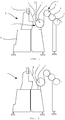
- Fig. 1 shows a schematic representation of a first embodiment of the warp knitting machine 1 according to the invention with a pickup roller 2.
- the warp knitting machine 1 has a tee bar 3, at which a knitted fabric 4 produced by the warp knitting machine 1 leaves an effective range of the warp knitting machine 1.
- the pickup roller 2 receives the knitted fabric 4.
- the pickup roller 2 is eccentrically connected to a take-up shaft 5.
- the take-up shaft 5 is driven by a gear through a main shaft of the warp knitting machine 1 and set in rotation.
- the main shaft is arranged in a machine bed 6 of the warp knitting machine 1.
- the knitted fabric 4 runs in a casserole area 7 on the pickup roller 2.
- the eccentric movement of the pickup roller 5 leads to a homogenization of the fabric take-off tension, with which the knitted fabric 4 is subtracted from the tee bar 3 and from the effective range of the warp knitting machine 1.
- the knitted fabric 4 always lies in sections on a surface 21 of the pickup roller 2.
- the take-up shaft 5 is coupled to the main shaft in such a way that the fabric take-off tension is always adapted to the knitting process. This results in a knitted fabric 4 special quality.
- the pickup roller 2 are downstream of three take-off rollers 8, which carry the knitted fabric 4 on.
- the take-up roll 2, together with the take-off rolls 8, forms a take-off device 9 of the warp knitting machine.
- Fig. 2 shows a schematic representation of the first embodiment of the warp knitting machine 1 according to the invention, wherein the pickup roller 2 is in a different position. By a rotation of the take-up shaft 5, the position of the pickup roller 2 has been changed to keep the cloth take-off tension approximately constant.
- Fig. 3 shows a schematic representation of a second embodiment of the warp knitting machine 1 according to the invention with a pickup roller 2, which is mounted on a translationally displaceable pick-up shaft 5.
- a carriage 11 is arranged, which is displaceable transversely to a longitudinal axis of the take-up shaft 5.
- the take-up shaft 5 is rotatably mounted in the carriage 11.
- a drive moves the carriage 11 up and down.
- the pickup roller 2 is thus displaced translationally along a movement axis 12, which is symbolized by a double arrow.
- the translational displacement of Pick-up roller 2 allows a homogenization of the fabric withdrawal tension.
- Fig. 4 shows a schematic representation of the second embodiment of the warp knitting machine 1 according to the invention, wherein the pickup roller 2 has been translationally displaced. This makes it possible to keep the fabric withdrawal tension approximately constant.
- Fig. 5 shows a schematic representation of a third embodiment of the warp knitting machine 1 according to the invention with a displaceable guide rod 13. Shown is a view of an end face of the guide rod 13, which has a cylindrical shape.
- the guide rod 13 is cylindrical and abuts on a knitted fabric 4 produced by the warp knitting machine 1.
- the knitted fabric 4 runs in a casserole area 7 on the guide rod 13 and is then guided to a plurality of draw-off rollers 8, which deduct the knitted fabric 4 from the effective range.
- the lever 15 is pivoted by a drive and thereby pressed against the knitted fabric to keep the fabric withdrawal tension approximately constant.
- Fig. 6 shows a schematic representation of an effective region 16 of a warp knitting machine.
- a knitting needle 17 moves past guide needles 18 in order to catch warp threads 19 guided by the guide needles 18.
- the knitting needle 17 and the guide needles 18 are knitting tools.
- Each guide needle 18 is held by a guide bar 20. Since the knitting needle 17 swings past several guide needles 18, warp threads are captured in a comparatively large effective range 16.
- the knitting needle 17 moves in the fürschwingterrorism along a knitting needle path 21, which is symbolized by a double arrow.
- the guide bars 20 perform a countermovement to the knitting needle 17.
- the movements of the knitting tools and the size of the effective area 16, in which the knitted fabric arises cause the knitted fabric usually subject to a variable fabric take-off tension. This is compensated by the fabric removal device of the warp knitting machine according to the invention.
Landscapes
- Engineering & Computer Science (AREA)
- Textile Engineering (AREA)
- Knitting Machines (AREA)
Abstract
Description
- Die Erfindung betrifft eine Kettenwirkmaschine mit einem Wirkbereich, in dem Wirkwerkzeuge zur Erzeugung einer Wirkware angeordnet sind, und mit einer Warenabzugseinrichtung zum Abzug einer von der Kettenwirkmaschine bei einem Wirkprozess hergestellten Wirkware aus dem Wirkbereich.
- Bei einer Kettenwirkmaschine handelt es sich um eine Textilmaschine, die aus Kettfäden bei einem maschenbildenden Vorgang eine Wirkware erzeugt. Die Maschenbildung erfolgt in dem Wirkbereich der Kettenwirkmaschine. Dabei kommen typischerweise Wirkwerkzeuge wie beispielsweise Wirknadeln und Legenadeln zur Verwendung. Kettenwirkmaschinen weisen mehrere Barren auf, wobei an einer Barre jeweils eine Vielzahl von Wirkwerkzeugen angeordnet sind. Da mittels einer Barre eine Vielzahl von Wirkwerkzeugen gleichzeitig bewegt werden können, werden bei dem Wirkprozess eine Vielzahl von Maschen gleichzeitig gebildet. Hierin liegt die besonders hohe Produktionsleistung von Kettenwirkmaschinen begründet.
- Warenabzugseinrichtungen für Kettenwirkmaschinen sind aus dem Stand der Technik bekannt. Eine Kettenwirkmaschine mit einer Warenabzugseinrichtung wird beispielsweise in der Offenlegungsschrift
DE 10 2010 046 587 B4 gezeigt. Die darin offenbarte Warenabzugseinrichtung weist mehrere zylinderförmige Abzugswalzen auf. Diese werden durch einen Antrieb in Rotation versetzt und ziehen die Wirkware somit aus dem Wirkbereich ab. Die Wirkware wird anschließend auf eine Wickelwalze aufgewickelt. - Der Erfindung liegt die Aufgabe zu Grunde, eine Kettenwirkmaschine bereitzustellen, die eine Wirkware mit einer verbesserten Warenqualität herstellt.
- Die Aufgabe wird gelöst, indem eine Kettenwirkmaschine bereitgestellt wird, bei der die Warenabzugseinrichtung ein Warenführungselement mit einem Auflaufbereich aufweist, in dem die Wirkware auf das Warenführungselement aufläuft, wobei ein Abstand zwischen einem ortsfesten Maschinenbett der Kettenwirkmaschine und dem Auflaufbereich des Warenführungselements veränderlich ist, sodass eine Warenabzugsspannung, mit der die Wirkware aus dem Wirkbereich abgezogen wird, durch eine Änderung des Abstands vergleichmäßigt werden kann.
- Wie sich herausgestellt hat, ergibt sich hierdurch eine verbesserte Warenqualität. Bei dem Wirkprozess bewegen sich Wirknadeln der Kettenwirkmaschine, um die Wirkware zu bilden. Dabei kann die Maschenbildung an veränderlichen Positionen im Wirkbereich erfolgen, was sich auf die Abzugsspannung auswirkt. Der Auflaufbereich des Warenführungselements wird durch einen Abschnitt einer Oberfläche des Warenführungselements gebildet. Der Abstand zwischen dem Maschinenbett und dem Auflaufbereich ist variabel. Wenn sich der Auflaufbereich von dem Maschinenbett entfernt, dann erhöht sich die Warenabzugsspannung. Wird der Auflaufbereich in Richtung des Maschinenbetts bewegt, dann verringert sich die Warenabzugsspannung.
- Wie sich herausgestellt hat, führt die erfindungsgemäße Vergleichmäßigung der Warenabzugsspannung zu einer gleichmäßigeren Maschengröße bei der erzeugten Wirkware. Erfindungsgemäß wird die Position des Auflaufbereichs daran angepasst, an welcher Position im Wirkbereich die Maschenbildung erfolgt. Dies macht sich insbesondere bei hohen Maschinendrehzahlen bemerkbar.
- Es wäre zwar alternativ denkbar, die Aufnahmewalze so anzutreiben, dass sie eine veränderliche Rotationsgeschwindigkeit und/oder -richtung aufweist. Auch dadurch ließe sich eine Vergleichmäßigung der Warenabzugsspannung erreichen. Dies wäre allerdings in der Umsetzung sehr aufwändig.
- Es ist vorteilhaft, wenn das Warenführungselement eine drehbare Aufnahmewalze ist. Die Aufnahmewalze kann die Wirkware mittels einer Drehbewegung weiterbefördern. Die Aufnahmewalze weist bevorzugt eine zylinderförmige Form auf. Sie kann jedoch alternativ auch eine abweichende Form aufweisen.
- Es ist bevorzugt, wenn die Aufnahmewalze exzentrisch antreibbar ist. Dies wird besonders bevorzugt so umgesetzt, dass die Warenabzugseinrichtung eine drehbar gelagerte Aufnahmewelle zum Antrieb der Aufnahmewalze aufweist, wobei die Aufnahmewelle zu der Aufnahmewalze exzentrisch angeordnet ist. Die Aufnahmewelle kann erfindungsgemäß durch einen Antrieb in Rotation versetzt werden. Aufgrund der exzentrischen Anordnung der Aufnahmewelle zu der Aufnahmewalze führt die Aufnahmewalze eine Bewegung durch, bei der sich der Abstand des Auflaufbereichs von dem Wirkbereich ständig ändert. Die Warenabzugsspannung wird dadurch vergleichmäßigt.
- Gemäß einer möglichen Variante der Erfindung ist die Aufnahmewelle fest mit der Aufnahmewalze verbunden. Gemäß einer alternativen Variante der Erfindung ist die Aufnahmewelle mit einer Laufscheibe fest verbunden, wobei die Aufnahmewelle zu der Laufscheibe exzentrisch angeordnet ist. Die Aufnahmewalze ist drehbar auf der Laufscheibe gelagert.
- Falls ein exzentrischer Antrieb nicht vorgesehen werden soll, dann ist es alternativ möglich, dass die Aufnahmewalze translatorisch verlagerbar ist. Die Oberfläche der Aufnahmewalze unterliegt somit einer Verschiebungsbewegung, wodurch die Warenabzugsspannung vergleichmäßigt wird. Die Aufnahmewalze kann sich nichtsdestotrotz gleichzeitig in Rotation befinden. Die translatorische Verlagerung kann dadurch erreicht werden, dass die Warenabzugseinrichtung eine drehbar gelagerte Aufnahmewelle zum Antrieb der Aufnahmewalze aufweist, wobei die Aufnahmewelle quer zu einer Längsachse der Aufnahmewelle verlagerbar ist. Die Aufnahmewelle kann erfindungsgemäß mit einer Einrichtung zur Verlagerung der Aufnahmewelle in einer Richtung quer zu der Längsachse der Aufnahmewelle ausgestattet sein. Wenn die Aufnahmewelle quer zu ihrer Längsachse entlang einer gedachten Querachse bewegt wird, dann wird der Bewegung der Aufnahmewalze eine translatorische Komponente hinzugefügt. Die Querachse, entlang der die Aufnahmewelle bewegt wird, schließt vorzugsweise mit der Längsachse der Aufnahmewelle einen Winkel von 90° ein. Die Aufnahmewalze kann auf der Aufnahmewelle drehbar gelagert sein. Es ist alternativ möglich, dass die Aufnahmewalze mit der Aufnahmewelle fest verbunden ist und dass die Kettenwirkmaschine einen Antrieb aufweist, der die Aufnahmewelle in Rotation versetzt.
- Gemäß einer besonderen Ausführungsform der Erfindung ist das Warenführungselement eine verlagerbare Führungsstange. Dabei kann es sich erfindungsgemäß um einen Metallstab oder einen Stab aus Kunststoff handeln. Die Führungsstange kann erfindungsgemäß an einem verschwenkbaren Hebel befestigt sein. Erfindungsgemäß wird eine Wirkware durch mindestens eine Abzugswalze von der Wirkstelle abgezogen und an der Führungsstange vorbeigeführt. Wird die Führungsstange durch eine Verschwenkung des Hebels verlagert, sodass die Führungsstange an die Wirkware angedrückt wird, dann wird die Wirkware deformiert und die Warenabzugsspannung steigt an. Gemäß einer vorteilhaften Ausprägung der Erfindung ist der Traghebel an einem Antriebshebel der Kettenwirkmaschine befestigt, der eine Barre in eine Konträrbewegung versetzt. Bei der Konträrbewegung handelt es sich um eine zur Maschenbildung notwendige Schwingbewegung der Barre.
- Es ist vorteilhaft, wenn die Warenabzugseinrichtung mindestens eine Abzugswalze aufweist, die dem Warenführungselement nachgeordnet ist. Die mindestens eine Abzugswalze wird durch einen Antrieb in Rotation versetzt, sodass eine Abzugskraft auf die Wirkware ausgeübt wird. Gemäß Ausführungsformen der Erfindung kann der mindestens einen Abzugswalze eine Wickelwalze nachgeordnet sein, auf der die Wirkware aufgewickelt wird.
- Das Warenführungselement ist vorzugsweise mit einem Antriebselement der Kettenwirkmaschine gekoppelt. Gemäß Ausführungsformen der Erfindung kann das Antriebselement das Warenführungselement in eine rotatorische und/oder eine translatorische Bewegung versetzen. Erfindungsgemäß kann es sich bei dem Antriebselement um eine Hauptwelle der Kettenwirkmaschine handeln. Diese kann mit dem Warenführungselement gekoppelt sein. Die Hauptwelle ist vorzugsweise außerdem mit mindestens einer Barre der Kettenwirkmaschine gekoppelt, sodass sie sowohl den Wirkprozess als auch die Warenabzugseinrichtung steuert.
- Die Erfindung betrifft ferner eine Warenabzugseinrichtung für eine Kettenwirkmaschine zum Abzug einer von der Kettenwirkmaschine bei einem Wirkprozess hergestellten Wirkware. Erfindungsgemäß weist die Warenabzugseinrichtung ein Warenführungselement mit einem Auflaufbereich auf, in dem die Wirkware auf das Warenführungselement aufläuft, wobei der Auflaufbereich nicht ortsfest ist, sodass eine Warenabzugsspannung, mit der die Wirkware aus dem Wirkbereich abgezogen wird, vergleichmäßigt werden kann. Das Warenführungselement ist bevorzugt eine drehbare Aufnahmewalze. Besonders bevorzugt ist die Aufnahmewalze exzentrisch antreibbar. Dabei ist es erfindungsgemäß möglich, dass die Warenabzugseinrichtung eine drehbar gelagerte Aufnahmewelle zum Antrieb der Aufnahmewalze aufweist, wobei die Aufnahmewelle zu der Aufnahmewalze exzentrisch angeordnet ist. Gemäß einer weiteren Ausführungsform der Erfindung ist es möglich, dass die Aufnahmewalze translatorisch verlagerbar ist.
- Die Zeichnungen stellen mögliche Ausführungsformen der Erfindung dar. Dabei zeigt:
-
Fig. 1 eine schematische Darstellung einer ersten Ausführungsform der erfindungsgemäßen Kettenwirkmaschine mit einer Aufnahmewalze, -
Fig. 2 eine schematische Darstellung der ersten Ausführungsform der erfindungsgemäßen Kettenwirkmaschine, wobei sich die Aufnahmewalze in einer abweichenden Drehstellung befindet, -
Fig. 3 eine schematische Darstellung einer zweiten Ausführungsform der erfindungsgemäßen Kettenwirkmaschine mit einer Aufnahmewalze, die auf einer translatorisch verlagerbaren Aufnahmewelle gelagert ist, -
Fig. 4 eine schematische Darstellung der zweiten Ausführungsform, wobei die Aufnahmewalze translatorisch verlagert worden ist, -
Fig. 5 eine schematische Darstellung einer dritten Ausführungsform der erfindungsgemäßen Kettenwirkmaschine mit einer verlagerbaren Führungsstange und -
Fig. 6 eine schematische Darstellung eines Wirkbereichs einer erfindungsgemäßen Kettenwirkmaschine. -
Fig. 1 zeigt eine schematische Darstellung einer ersten Ausführungsform der erfindungsgemäßen Kettenwirkmaschine 1 mit einer Aufnahmewalze 2. Die Kettenwirkmaschine 1 weist eine Abschlagbarre 3 auf, an der eine von der Kettenwirkmaschine 1 erzeugte Wirkware 4 einen Wirkbereich der Kettenwirkmaschine 1 verlässt. Die Aufnahmewalze 2 nimmt die Wirkware 4 auf. Die Aufnahmewalze 2 ist mit einer Aufnahmewelle 5 exzentrisch verbunden. Die Aufnahmewelle 5 wird über ein Getriebe durch eine Hauptwelle der Kettenwirkmaschine 1 angetrieben und in Rotation versetzt. Die Hauptwelle ist in einem Maschinenbett 6 der Kettenwirkmaschine 1 angeordnet. Die Wirkware 4 läuft in einem Auflaufbereich 7 auf die Aufnahmewalze 2 auf. Die exzentrische Bewegung der Aufnahmewalze 5 führt zu einer Vergleichmäßigung der Warenabzugsspannung, mit der die Wirkware 4 von der Abschlagbarre 3 und aus dem Wirkbereich der Kettenwirkmaschine 1 abgezogen wird. Die Wirkware 4 liegt dabei stets abschnittsweise an einer Oberfläche 21 der Aufnahmewalze 2 an. Die Aufnahmewelle 5 ist mit der Hauptwelle solchermaßen gekoppelt, dass die Warenabzugsspannung dem Wirkprozess stets angepasst ist. Dadurch ergibt sich eine Wirkware 4 besonderer Güte. Der Aufnahmewalze 2 sind drei Abzugswalzen 8 nachgeordnet, die die Wirkware 4 weiterbefördern. Die Aufnahmewalze 2 bildet gemeinsam mit den Warenabzugswalzen 8 eine Warenabzugseinrichtung 9 der Kettenwirkmaschine. -
Fig. 2 zeigt eine schematische Darstellung der ersten Ausführungsform der erfindungsgemäßen Kettenwirkmaschine 1, wobei sich die Aufnahmewalze 2 in einer abweichenden Position befindet. Durch eine Drehung der Aufnahmewelle 5 ist die Position der Aufnahmewalze 2 geändert worden, um die Warenabzugsspannung annähernd konstant zu halten. -
Fig. 3 zeigt eine schematische Darstellung einer zweiten Ausführungsform der erfindungsgemäßen Kettenwirkmaschine 1 mit einer Aufnahmewalze 2, die auf einer translatorisch verlagerbaren Aufnahmewelle 5 gelagert ist. In dem Stützelement 10 ist ein Schlitten 11 angeordnet, der quer zu einer Längsachse der Aufnahmewelle 5 verlagerbar ist. Die Aufnahmewelle 5 ist in dem Schlitten 11 drehbar gelagert. Ein Antrieb bewegt den Schlitten 11 auf und ab. Die Aufnahmewalze 2 wird folglich translatorisch entlang einer Bewegungsachse 12 verlagert, die durch einen Doppelpfeil symbolisiert wird. Die translatorische Verlagerung der Aufnahmewalze 2 erlaubt eine Vergleichmäßigung der Warenabzugsspannung. -
Fig. 4 zeigt eine schematische Darstellung der zweiten Ausführungsform der erfindungsgemäßen Kettenwirkmaschine 1, wobei die Aufnahmewalze 2 translatorisch verlagert worden ist. Dies erlaubt es, die Warenabzugsspannung annähernd konstant zu halten. -
Fig. 5 zeigt eine schematische Darstellung einer dritten Ausführungsform der erfindungsgemäßen Kettenwirkmaschine 1 mit einer verlagerbaren Führungsstange 13. Gezeigt wird eine Ansicht auf eine Stirnfläche der Führungsstange 13, die eine zylindrische Form aufweist. Die Führungsstange 13 ist zylinderförmig ausgebildet und liegt an einer von der Kettenwirkmaschine 1 erzeugten Wirkware 4 an. Die Wirkware 4 läuft in einem Auflaufbereich 7 auf die Führungsstange 13 auf und wird anschließend zu mehreren Abzugswalzen 8 geführt, die die Wirkware 4 aus dem Wirkbereich abziehen. Ein um eine Schwenkachse 14 verschwenkbar gelagerter Hebel 15 trägt die Führungsstange 12. Der Hebel 15 wird durch einen Antrieb verschwenkt und dabei an die Wirkware gedrückt, um die Warenabzugsspannung annähernd konstant zu halten. -
Fig. 6 zeigt eine schematische Darstellung eines Wirkbereichs 16 einer Kettenwirkmaschine. In dem Wirkbereich 16 bewegt sich eine Wirknadel 17 an Legenadeln 18 vorbei, um von den Legenadeln 18 geführte Kettfäden 19 zu fangen. Bei der Wirknadel 17 und den Legenadeln 18 handelt es sich um Wirkwerkzeuge. Jede Legenadel 18 wird durch eine Legebarre 20 gehalten. Da die Wirknadel 17 an mehreren Legenadeln 18 vorbeischwingt, werden Kettfäden in einem vergleichsweise großen Wirkbereich 16 eingefangen. Die Wirknadel 17 bewegt sich bei der Durchschwingbewegung entlang eines Wirknadelpfads 21, der durch einen Doppelpfeil symbolisiert wird. Die Legebarren 20 führen eine Gegenbewegung zu der Wirknadel 17 aus. Die Bewegungen der Wirkwerkzeuge und die Größe des Wirkbereichs 16, in dem die Wirkware entsteht, führen dazu, dass die Wirkware normalerweise einer veränderlichen Warenabzugsspannung unterliegt. Dies wird durch die Warenabzugseinrichtung der erfindungsgemäßen Kettenwirkmaschine kompensiert. -
- 1.
- Kettenwirkmaschine
- 2.
- Aufnahmewalze
- 3.
- Abschlagbarre
- 4.
- Wirkware
- 5.
- Aufnahmewelle
- 6.
- Maschinenbett
- 7.
- Auflaufbereich
- 8.
- Abzugswalze
- 9.
- Warenabzugseinrichtung
- 10.
- Stützelement
- 11.
- Schlitten
- 12.
- Bewegungsachse
- 13.
- Führungsstange
- 14.
- Schwenkachse
- 15.
- Hebel
- 16.
- Wirkbereich
- 17.
- Wirknadeln
- 18.
- Legenadel
- 19.
- Kettfaden
- 20.
- Legebarre
- 21.
- Oberfläche
Claims (15)
- Kettenwirkmaschine (1) mit einem Wirkbereich (16), in dem Wirkwerkzeuge zur Erzeugung einer Wirkware (4) angeordnet sind, und mit einer Warenabzugseinrichtung (9) zum Abzug einer von der Kettenwirkmaschine (1) bei einem Wirkprozess hergestellten Wirkware (4) aus dem Wirkbereich (16), dadurch gekennzeichnet, dass die Warenabzugseinrichtung (9) ein Warenführungselement mit einem Auflaufbereich (7) aufweist, in dem die Wirkware (4) auf das Warenführungselement aufläuft, wobei ein Abstand zwischen einem ortsfesten Maschinenbett (6) der Kettenwirkmaschine (1) und dem Auflaufbereich (7) des Warenführungselements veränderlich ist, sodass eine Warenabzugsspannung, mit der die Wirkware (4) aus dem Wirkbereich (16) abgezogen wird, durch eine Änderung des Abstands vergleichmäßigt werden kann.
- Kettenwirkmaschine (1) nach Anspruch 1, dadurch gekennzeichnet, dass das Warenführungselement eine drehbare Aufnahmewalze (2) ist.
- Kettenwirkmaschine nach Anspruch 2, dadurch gekennzeichnet, dass die Aufnahmewalze (2) exzentrisch antreibbar ist.
- Kettenwirkmaschine (1) nach Anspruch 2 oder 3, dadurch gekennzeichnet, dass die Warenabzugseinrichtung (9) eine drehbar gelagerte Aufnahmewelle (5) zum Antrieb Aufnahmewalze (2) aufweist, wobei die Aufnahmewelle (5) zu der Aufnahmewalze (2) exzentrisch angeordnet ist.
- Kettenwirkmaschine (1) nach Anspruch 2, dadurch gekennzeichnet, dass die Aufnahmewalze (2) translatorisch verlagerbar ist.
- Kettenwirkmaschine (1) nach Anspruch 5, dadurch gekennzeichnet, dass die Warenabzugseinrichtung (9) eine drehbar gelagerte Aufnahmewelle (5) zum Antrieb der Aufnahmewalze (2) aufweist, wobei die Aufnahmewelle (5) quer zu einer Längsachse der Aufnahmewelle (5) verlagerbar ist.
- Kettenwirkmaschine (1) nach Anspruch 1, dadurch gekennzeichnet, dass das Warenführungselement eine verlagerbare Führungsstange (13) ist.
- Kettenwirkmaschine (1) nach einem der vorhergehenden Ansprüche, dadurch gekennzeichnet, dass die Warenabzugseinrichtung (9) mindestens eine Abzugswalze (8) aufweist, die dem Warenführungselement nachgeordnet ist.
- Kettenwirkmaschine (1) nach einem der vorhergehenden Ansprüche, dadurch gekennzeichnet, dass das Warenführungselement mit einem Antriebselement der Kettenwirkmaschine (1) gekoppelt ist.
- Kettenwirkmaschine (1) nach Anspruch 9, dadurch gekennzeichnet, dass das Antriebselement eine Hauptwelle der Kettenwirkmaschine (1) ist.
- Warenabzugseinrichtung (9) für eine Kettenwirkmaschine (1) zum Abzug einer von der Kettenwirkmaschine (1) bei einem Wirkprozess hergestellten Wirkware (4), dadurch gekennzeichnet, dass die Warenabzugseinrichtung (9) ein Warenführungselement mit einem Auflaufbereich (7) aufweist, in dem die Wirkware (4) auf das Warenführungselement aufläuft, und wobei der Auflaufbereich (7) nicht ortsfest ist, sodass eine Warenabzugsspannung, mit der die Wirkware (4) aus dem Wirkbereich (16) abgezogen wird, vergleichmäßigt werden kann.
- Kettenwirkmaschine (1) nach Anspruch 11, dadurch gekennzeichnet, dass das Warenführungselement eine drehbare Aufnahmewalze (2) ist.
- Kettenwirkmaschine nach Anspruch 12, dadurch gekennzeichnet, dass die Aufnahmewalze (2) exzentrisch antreibbar ist.
- Kettenwirkmaschine (1) nach Anspruch 12 oder 13, dadurch gekennzeichnet, dass die Warenabzugseinrichtung (9) eine drehbar gelagerte Aufnahmewelle (5) zum Antrieb Aufnahmewalze (2) aufweist, wobei die Aufnahmewelle (5) zu der Aufnahmewalze (2) exzentrisch angeordnet ist.
- Warenabzugseinrichtung (9) nach Anspruch 12, dadurch gekennzeichnet, dass die Aufnahmewalze (2) translatorisch verlagerbar ist.
Priority Applications (3)
| Application Number | Priority Date | Filing Date | Title |
|---|---|---|---|
| EP19163532.5A EP3495541B1 (de) | 2019-03-18 | 2019-03-18 | Kettenwirkmaschine und warenabzugseinrichtung für eine kettenwirkmaschine |
| CN201911197713.0A CN111719232B (zh) | 2019-03-18 | 2019-11-29 | 经编机和用于经编机的织物牵拉装置 |
| JP2020040403A JP7178381B2 (ja) | 2019-03-18 | 2020-03-10 | 経編機及び経編機のための生地引出装置 |
Applications Claiming Priority (1)
| Application Number | Priority Date | Filing Date | Title |
|---|---|---|---|
| EP19163532.5A EP3495541B1 (de) | 2019-03-18 | 2019-03-18 | Kettenwirkmaschine und warenabzugseinrichtung für eine kettenwirkmaschine |
Publications (3)
| Publication Number | Publication Date |
|---|---|
| EP3495541A2 true EP3495541A2 (de) | 2019-06-12 |
| EP3495541A3 EP3495541A3 (de) | 2019-09-11 |
| EP3495541B1 EP3495541B1 (de) | 2021-05-19 |
Family
ID=65818375
Family Applications (1)
| Application Number | Title | Priority Date | Filing Date |
|---|---|---|---|
| EP19163532.5A Active EP3495541B1 (de) | 2019-03-18 | 2019-03-18 | Kettenwirkmaschine und warenabzugseinrichtung für eine kettenwirkmaschine |
Country Status (3)
| Country | Link |
|---|---|
| EP (1) | EP3495541B1 (de) |
| JP (1) | JP7178381B2 (de) |
| CN (1) | CN111719232B (de) |
Cited By (1)
| Publication number | Priority date | Publication date | Assignee | Title |
|---|---|---|---|---|
| EP3795729A1 (de) * | 2019-09-18 | 2021-03-24 | Groz-Beckert KG | Platine, platinenanordnung und kettenwirkmaschine |
Families Citing this family (1)
| Publication number | Priority date | Publication date | Assignee | Title |
|---|---|---|---|---|
| CN116513885B (zh) * | 2022-01-24 | 2026-06-09 | 达贺实业有限公司 | 针织机织物的输送导引装置 |
Citations (1)
| Publication number | Priority date | Publication date | Assignee | Title |
|---|---|---|---|---|
| DE102010046587B4 (de) | 2010-09-25 | 2018-04-12 | Karl Mayer China Ltd. | Wirkmaschine |
Family Cites Families (14)
| Publication number | Priority date | Publication date | Assignee | Title |
|---|---|---|---|---|
| DE862040C (de) * | 1950-04-14 | 1953-01-08 | Robert Reiner | Warenabzugsvorrichtung, insbesondere fuer Flachkettenwirkmaschinen |
| DE1171554B (de) * | 1960-02-08 | 1964-06-04 | Karl Mayer Erste Hess Wirkmasc | Kettenwirkmaschine mit einer Warenabzugsvorrichtung |
| JPS5713345Y2 (de) * | 1978-08-22 | 1982-03-17 | ||
| JPS6133452A (ja) * | 1984-07-24 | 1986-02-17 | Kataoka Kikai Seisakusho:Kk | 供給シ−トの張力制御装置 |
| US5754913A (en) * | 1995-06-20 | 1998-05-19 | Ecrm Incorporated | Sheet transporting |
| DE19620670C2 (de) * | 1996-05-22 | 1998-07-23 | Liba Maschf | Vorrichtung zum Aufwickeln einer Wirkwarenbahn |
| JP3827239B2 (ja) * | 2004-02-27 | 2006-09-27 | 福井経編興業株式会社 | 経編機における編地巻き取り装置、及びその巻き取り方法 |
| CN201202004Y (zh) * | 2008-04-03 | 2009-03-04 | 常州市天益纺织机械有限公司 | 一种经编机的牵拉辊装置 |
| CN201343623Y (zh) * | 2009-01-15 | 2009-11-11 | 俞云泉 | 一体罗拉 |
| JP6019768B2 (ja) * | 2011-09-19 | 2016-11-02 | 株式会社リコー | ウェブ搬送装置、印刷装置及び張力制御方法 |
| CN203795077U (zh) * | 2014-01-21 | 2014-08-27 | 苏州宜新织造有限公司 | 织造卷取系统 |
| CN203807696U (zh) * | 2014-03-23 | 2014-09-03 | 浙江莎美实业股份有限公司 | 一种针织机用罗拉牵引装置 |
| TWM494154U (zh) * | 2014-10-16 | 2015-01-21 | Twu Nan Machinery Co Ltd | 吊裝用護角 |
| KR102033343B1 (ko) * | 2019-05-10 | 2019-10-18 | 주식회사 중앙산업 | 차양지 제조장치 및 이를 이용하여 제조된 차양지 |
-
2019
- 2019-03-18 EP EP19163532.5A patent/EP3495541B1/de active Active
- 2019-11-29 CN CN201911197713.0A patent/CN111719232B/zh active Active
-
2020
- 2020-03-10 JP JP2020040403A patent/JP7178381B2/ja active Active
Patent Citations (1)
| Publication number | Priority date | Publication date | Assignee | Title |
|---|---|---|---|---|
| DE102010046587B4 (de) | 2010-09-25 | 2018-04-12 | Karl Mayer China Ltd. | Wirkmaschine |
Cited By (2)
| Publication number | Priority date | Publication date | Assignee | Title |
|---|---|---|---|---|
| EP3795729A1 (de) * | 2019-09-18 | 2021-03-24 | Groz-Beckert KG | Platine, platinenanordnung und kettenwirkmaschine |
| WO2021053014A1 (de) * | 2019-09-18 | 2021-03-25 | Groz-Beckert Kg | Platine, platinenanordnung und kettenwirkmaschine |
Also Published As
| Publication number | Publication date |
|---|---|
| EP3495541A3 (de) | 2019-09-11 |
| CN111719232B (zh) | 2022-05-13 |
| JP2020153056A (ja) | 2020-09-24 |
| JP7178381B2 (ja) | 2022-11-25 |
| CN111719232A (zh) | 2020-09-29 |
| EP3495541B1 (de) | 2021-05-19 |
Similar Documents
| Publication | Publication Date | Title |
|---|---|---|
| EP3495541B1 (de) | Kettenwirkmaschine und warenabzugseinrichtung für eine kettenwirkmaschine | |
| WO2012059317A1 (de) | Strickmaschine | |
| DE102008047684B4 (de) | Wirkmaschine, insbesondere Kettenwirkmaschine | |
| DE2408924C2 (de) | Vorrichtung zum Herstellen von Maschenwaren | |
| EP2196568A1 (de) | Schlossteil und Strickmaschine | |
| DE202019103375U1 (de) | Kettenwirkmaschine | |
| DE102005062403B3 (de) | Vorrichtung und Verfahren zur Erzeugung eines Abstandsgestricks | |
| EP2067887B1 (de) | Raschelmaschine und Verfahren zur Herstellung eines Abstandsgewirkes sowie Abstandsgewirke | |
| DE10140864A1 (de) | Vorrichtung zum Vernadeln eines förderbaren Faservlieses | |
| EP3363939B1 (de) | Doppelfonturige kettenwirkmaschine | |
| DE102008019467B4 (de) | Verfahren zum Betrieb einer Stickmaschine mit schlaufenformenden Element und Stickmaschine nach dem Verfahren | |
| EP1469110A1 (de) | Verfahren und Strickmaschine zur Herstellung von Strickwaren, insbesondere aus hartem, unelastischem Fadenmaterial | |
| EP3645774B1 (de) | Vorrichtung und verfahren zum vorlegen von fäden und textilmaschine | |
| EP1592829B1 (de) | Wirkmaschinen | |
| WO2016091552A1 (de) | Rundstrickmaschine | |
| DE69127655T2 (de) | Abzugvorrichtung für Strickmaschinen | |
| EP3754077B1 (de) | Verfahren und strickvorrichtung zum plattieren auf einer mit schiebernadeln bestückten rundstrickmaschine | |
| DE2212935A1 (de) | Kettenwirkmaschine | |
| EP3795730B1 (de) | Kettenwirkmaschine und verfahren zum erzeugen von kettenwirkware | |
| EP3511460A2 (de) | Kettenwirkmaschine und verfahren zur bedienerunterstützung bei einer kettenwirkmaschine | |
| DE704565C (de) | Strickmaschine zur Herstellung von Huellen fuer strangfoermige Koerper | |
| DE102024125156A1 (de) | Anlage, Verfahren und Walze zur Verfestigung einer textilen Warenbahn | |
| DE2329230C3 (de) | Strickvorrichtung | |
| DE202012001302U1 (de) | Maschine zur Herstellung und/oder Behandlung einer Faserbahn | |
| DE2316642C3 (de) | Rundstrickmaschine zur Herstellung von Kulierware |
Legal Events
| Date | Code | Title | Description |
|---|---|---|---|
| PUAI | Public reference made under article 153(3) epc to a published international application that has entered the european phase |
Free format text: ORIGINAL CODE: 0009012 |
|
| STAA | Information on the status of an ep patent application or granted ep patent |
Free format text: STATUS: THE APPLICATION HAS BEEN PUBLISHED |
|
| AK | Designated contracting states |
Kind code of ref document: A2 Designated state(s): AL AT BE BG CH CY CZ DE DK EE ES FI FR GB GR HR HU IE IS IT LI LT LU LV MC MK MT NL NO PL PT RO RS SE SI SK SM TR |
|
| AX | Request for extension of the european patent |
Extension state: BA ME |
|
| PUAL | Search report despatched |
Free format text: ORIGINAL CODE: 0009013 |
|
| AK | Designated contracting states |
Kind code of ref document: A3 Designated state(s): AL AT BE BG CH CY CZ DE DK EE ES FI FR GB GR HR HU IE IS IT LI LT LU LV MC MK MT NL NO PL PT RO RS SE SI SK SM TR |
|
| AX | Request for extension of the european patent |
Extension state: BA ME |
|
| RIC1 | Information provided on ipc code assigned before grant |
Ipc: D04B 27/34 20060101AFI20190802BHEP |
|
| STAA | Information on the status of an ep patent application or granted ep patent |
Free format text: STATUS: REQUEST FOR EXAMINATION WAS MADE |
|
| RAP1 | Party data changed (applicant data changed or rights of an application transferred) |
Owner name: KARL MAYER R&D GMBH |
|
| 17P | Request for examination filed |
Effective date: 20200113 |
|
| RBV | Designated contracting states (corrected) |
Designated state(s): AL AT BE BG CH CY CZ DE DK EE ES FI FR GB GR HR HU IE IS IT LI LT LU LV MC MK MT NL NO PL PT RO RS SE SI SK SM TR |
|
| RAP1 | Party data changed (applicant data changed or rights of an application transferred) |
Owner name: KARL MAYER STOLL R&D GMBH |
|
| GRAP | Despatch of communication of intention to grant a patent |
Free format text: ORIGINAL CODE: EPIDOSNIGR1 |
|
| STAA | Information on the status of an ep patent application or granted ep patent |
Free format text: STATUS: GRANT OF PATENT IS INTENDED |
|
| INTG | Intention to grant announced |
Effective date: 20210204 |
|
| GRAS | Grant fee paid |
Free format text: ORIGINAL CODE: EPIDOSNIGR3 |
|
| GRAA | (expected) grant |
Free format text: ORIGINAL CODE: 0009210 |
|
| STAA | Information on the status of an ep patent application or granted ep patent |
Free format text: STATUS: THE PATENT HAS BEEN GRANTED |
|
| AK | Designated contracting states |
Kind code of ref document: B1 Designated state(s): AL AT BE BG CH CY CZ DE DK EE ES FI FR GB GR HR HU IE IS IT LI LT LU LV MC MK MT NL NO PL PT RO RS SE SI SK SM TR |
|
| REG | Reference to a national code |
Ref country code: GB Ref legal event code: FG4D Free format text: NOT ENGLISH |
|
| REG | Reference to a national code |
Ref country code: CH Ref legal event code: EP |
|
| REG | Reference to a national code |
Ref country code: DE Ref legal event code: R096 Ref document number: 502019001431 Country of ref document: DE |
|
| REG | Reference to a national code |
Ref country code: AT Ref legal event code: REF Ref document number: 1394050 Country of ref document: AT Kind code of ref document: T Effective date: 20210615 |
|
| REG | Reference to a national code |
Ref country code: IE Ref legal event code: FG4D Free format text: LANGUAGE OF EP DOCUMENT: GERMAN |
|
| REG | Reference to a national code |
Ref country code: LT Ref legal event code: MG9D |
|
| REG | Reference to a national code |
Ref country code: NL Ref legal event code: MP Effective date: 20210519 |
|
| PG25 | Lapsed in a contracting state [announced via postgrant information from national office to epo] |
Ref country code: LT Free format text: LAPSE BECAUSE OF FAILURE TO SUBMIT A TRANSLATION OF THE DESCRIPTION OR TO PAY THE FEE WITHIN THE PRESCRIBED TIME-LIMIT Effective date: 20210519 Ref country code: HR Free format text: LAPSE BECAUSE OF FAILURE TO SUBMIT A TRANSLATION OF THE DESCRIPTION OR TO PAY THE FEE WITHIN THE PRESCRIBED TIME-LIMIT Effective date: 20210519 Ref country code: FI Free format text: LAPSE BECAUSE OF FAILURE TO SUBMIT A TRANSLATION OF THE DESCRIPTION OR TO PAY THE FEE WITHIN THE PRESCRIBED TIME-LIMIT Effective date: 20210519 Ref country code: BG Free format text: LAPSE BECAUSE OF FAILURE TO SUBMIT A TRANSLATION OF THE DESCRIPTION OR TO PAY THE FEE WITHIN THE PRESCRIBED TIME-LIMIT Effective date: 20210819 |
|
| PG25 | Lapsed in a contracting state [announced via postgrant information from national office to epo] |
Ref country code: IS Free format text: LAPSE BECAUSE OF FAILURE TO SUBMIT A TRANSLATION OF THE DESCRIPTION OR TO PAY THE FEE WITHIN THE PRESCRIBED TIME-LIMIT Effective date: 20210919 Ref country code: GR Free format text: LAPSE BECAUSE OF FAILURE TO SUBMIT A TRANSLATION OF THE DESCRIPTION OR TO PAY THE FEE WITHIN THE PRESCRIBED TIME-LIMIT Effective date: 20210820 Ref country code: RS Free format text: LAPSE BECAUSE OF FAILURE TO SUBMIT A TRANSLATION OF THE DESCRIPTION OR TO PAY THE FEE WITHIN THE PRESCRIBED TIME-LIMIT Effective date: 20210519 Ref country code: PT Free format text: LAPSE BECAUSE OF FAILURE TO SUBMIT A TRANSLATION OF THE DESCRIPTION OR TO PAY THE FEE WITHIN THE PRESCRIBED TIME-LIMIT Effective date: 20210920 Ref country code: SE Free format text: LAPSE BECAUSE OF FAILURE TO SUBMIT A TRANSLATION OF THE DESCRIPTION OR TO PAY THE FEE WITHIN THE PRESCRIBED TIME-LIMIT Effective date: 20210519 Ref country code: PL Free format text: LAPSE BECAUSE OF FAILURE TO SUBMIT A TRANSLATION OF THE DESCRIPTION OR TO PAY THE FEE WITHIN THE PRESCRIBED TIME-LIMIT Effective date: 20210519 Ref country code: LV Free format text: LAPSE BECAUSE OF FAILURE TO SUBMIT A TRANSLATION OF THE DESCRIPTION OR TO PAY THE FEE WITHIN THE PRESCRIBED TIME-LIMIT Effective date: 20210519 Ref country code: NO Free format text: LAPSE BECAUSE OF FAILURE TO SUBMIT A TRANSLATION OF THE DESCRIPTION OR TO PAY THE FEE WITHIN THE PRESCRIBED TIME-LIMIT Effective date: 20210819 |
|
| PG25 | Lapsed in a contracting state [announced via postgrant information from national office to epo] |
Ref country code: NL Free format text: LAPSE BECAUSE OF FAILURE TO SUBMIT A TRANSLATION OF THE DESCRIPTION OR TO PAY THE FEE WITHIN THE PRESCRIBED TIME-LIMIT Effective date: 20210519 |
|
| PG25 | Lapsed in a contracting state [announced via postgrant information from national office to epo] |
Ref country code: SM Free format text: LAPSE BECAUSE OF FAILURE TO SUBMIT A TRANSLATION OF THE DESCRIPTION OR TO PAY THE FEE WITHIN THE PRESCRIBED TIME-LIMIT Effective date: 20210519 Ref country code: RO Free format text: LAPSE BECAUSE OF FAILURE TO SUBMIT A TRANSLATION OF THE DESCRIPTION OR TO PAY THE FEE WITHIN THE PRESCRIBED TIME-LIMIT Effective date: 20210519 Ref country code: DK Free format text: LAPSE BECAUSE OF FAILURE TO SUBMIT A TRANSLATION OF THE DESCRIPTION OR TO PAY THE FEE WITHIN THE PRESCRIBED TIME-LIMIT Effective date: 20210519 Ref country code: CZ Free format text: LAPSE BECAUSE OF FAILURE TO SUBMIT A TRANSLATION OF THE DESCRIPTION OR TO PAY THE FEE WITHIN THE PRESCRIBED TIME-LIMIT Effective date: 20210519 Ref country code: EE Free format text: LAPSE BECAUSE OF FAILURE TO SUBMIT A TRANSLATION OF THE DESCRIPTION OR TO PAY THE FEE WITHIN THE PRESCRIBED TIME-LIMIT Effective date: 20210519 Ref country code: ES Free format text: LAPSE BECAUSE OF FAILURE TO SUBMIT A TRANSLATION OF THE DESCRIPTION OR TO PAY THE FEE WITHIN THE PRESCRIBED TIME-LIMIT Effective date: 20210519 Ref country code: SK Free format text: LAPSE BECAUSE OF FAILURE TO SUBMIT A TRANSLATION OF THE DESCRIPTION OR TO PAY THE FEE WITHIN THE PRESCRIBED TIME-LIMIT Effective date: 20210519 |
|
| REG | Reference to a national code |
Ref country code: DE Ref legal event code: R097 Ref document number: 502019001431 Country of ref document: DE |
|
| PLBE | No opposition filed within time limit |
Free format text: ORIGINAL CODE: 0009261 |
|
| STAA | Information on the status of an ep patent application or granted ep patent |
Free format text: STATUS: NO OPPOSITION FILED WITHIN TIME LIMIT |
|
| 26N | No opposition filed |
Effective date: 20220222 |
|
| PG25 | Lapsed in a contracting state [announced via postgrant information from national office to epo] |
Ref country code: IS Free format text: LAPSE BECAUSE OF FAILURE TO SUBMIT A TRANSLATION OF THE DESCRIPTION OR TO PAY THE FEE WITHIN THE PRESCRIBED TIME-LIMIT Effective date: 20210919 Ref country code: AL Free format text: LAPSE BECAUSE OF FAILURE TO SUBMIT A TRANSLATION OF THE DESCRIPTION OR TO PAY THE FEE WITHIN THE PRESCRIBED TIME-LIMIT Effective date: 20210519 |
|
| PG25 | Lapsed in a contracting state [announced via postgrant information from national office to epo] |
Ref country code: MC Free format text: LAPSE BECAUSE OF FAILURE TO SUBMIT A TRANSLATION OF THE DESCRIPTION OR TO PAY THE FEE WITHIN THE PRESCRIBED TIME-LIMIT Effective date: 20210519 |
|
| REG | Reference to a national code |
Ref country code: CH Ref legal event code: PL |
|
| REG | Reference to a national code |
Ref country code: BE Ref legal event code: MM Effective date: 20220331 |
|
| PG25 | Lapsed in a contracting state [announced via postgrant information from national office to epo] |
Ref country code: LU Free format text: LAPSE BECAUSE OF NON-PAYMENT OF DUE FEES Effective date: 20220318 Ref country code: LI Free format text: LAPSE BECAUSE OF NON-PAYMENT OF DUE FEES Effective date: 20220331 Ref country code: IE Free format text: LAPSE BECAUSE OF NON-PAYMENT OF DUE FEES Effective date: 20220318 Ref country code: CH Free format text: LAPSE BECAUSE OF NON-PAYMENT OF DUE FEES Effective date: 20220331 |
|
| PG25 | Lapsed in a contracting state [announced via postgrant information from national office to epo] |
Ref country code: BE Free format text: LAPSE BECAUSE OF NON-PAYMENT OF DUE FEES Effective date: 20220331 |
|
| P01 | Opt-out of the competence of the unified patent court (upc) registered |
Effective date: 20230705 |
|
| GBPC | Gb: european patent ceased through non-payment of renewal fee |
Effective date: 20230318 |
|
| PG25 | Lapsed in a contracting state [announced via postgrant information from national office to epo] |
Ref country code: GB Free format text: LAPSE BECAUSE OF NON-PAYMENT OF DUE FEES Effective date: 20230318 |
|
| PG25 | Lapsed in a contracting state [announced via postgrant information from national office to epo] |
Ref country code: GB Free format text: LAPSE BECAUSE OF NON-PAYMENT OF DUE FEES Effective date: 20230318 |
|
| PG25 | Lapsed in a contracting state [announced via postgrant information from national office to epo] |
Ref country code: HU Free format text: LAPSE BECAUSE OF FAILURE TO SUBMIT A TRANSLATION OF THE DESCRIPTION OR TO PAY THE FEE WITHIN THE PRESCRIBED TIME-LIMIT; INVALID AB INITIO Effective date: 20190318 |
|
| PG25 | Lapsed in a contracting state [announced via postgrant information from national office to epo] |
Ref country code: MK Free format text: LAPSE BECAUSE OF FAILURE TO SUBMIT A TRANSLATION OF THE DESCRIPTION OR TO PAY THE FEE WITHIN THE PRESCRIBED TIME-LIMIT Effective date: 20210519 Ref country code: CY Free format text: LAPSE BECAUSE OF FAILURE TO SUBMIT A TRANSLATION OF THE DESCRIPTION OR TO PAY THE FEE WITHIN THE PRESCRIBED TIME-LIMIT Effective date: 20210519 |
|
| PG25 | Lapsed in a contracting state [announced via postgrant information from national office to epo] |
Ref country code: MT Free format text: LAPSE BECAUSE OF FAILURE TO SUBMIT A TRANSLATION OF THE DESCRIPTION OR TO PAY THE FEE WITHIN THE PRESCRIBED TIME-LIMIT Effective date: 20210519 |
|
| PGFP | Annual fee paid to national office [announced via postgrant information from national office to epo] |
Ref country code: FR Payment date: 20250324 Year of fee payment: 7 |
|
| PGFP | Annual fee paid to national office [announced via postgrant information from national office to epo] |
Ref country code: IT Payment date: 20250321 Year of fee payment: 7 |
|
| REG | Reference to a national code |
Ref country code: AT Ref legal event code: MM01 Ref document number: 1394050 Country of ref document: AT Kind code of ref document: T Effective date: 20240318 |
|
| PG25 | Lapsed in a contracting state [announced via postgrant information from national office to epo] |
Ref country code: AT Free format text: LAPSE BECAUSE OF NON-PAYMENT OF DUE FEES Effective date: 20240318 |
|
| PGFP | Annual fee paid to national office [announced via postgrant information from national office to epo] |
Ref country code: DE Payment date: 20260320 Year of fee payment: 8 |
|
| PGFP | Annual fee paid to national office [announced via postgrant information from national office to epo] |
Ref country code: AT Payment date: 20260410 Year of fee payment: 5 |
|
| PGFP | Annual fee paid to national office [announced via postgrant information from national office to epo] |
Ref country code: TR Payment date: 20260226 Year of fee payment: 8 |