EP3414123B1 - Verstellvorrichtung mit einer fremdkraftbetätigt und berührungslos verstellbaren verschlussklappe - Google Patents
Verstellvorrichtung mit einer fremdkraftbetätigt und berührungslos verstellbaren verschlussklappe Download PDFInfo
- Publication number
- EP3414123B1 EP3414123B1 EP17701282.0A EP17701282A EP3414123B1 EP 3414123 B1 EP3414123 B1 EP 3414123B1 EP 17701282 A EP17701282 A EP 17701282A EP 3414123 B1 EP3414123 B1 EP 3414123B1
- Authority
- EP
- European Patent Office
- Prior art keywords
- closure flap
- electrode
- opening
- adjustment
- flap
- Prior art date
- Legal status (The legal status is an assumption and is not a legal conclusion. Google has not performed a legal analysis and makes no representation as to the accuracy of the status listed.)
- Active
Links
Images


Classifications
-
- B—PERFORMING OPERATIONS; TRANSPORTING
- B60—VEHICLES IN GENERAL
- B60K—ARRANGEMENT OR MOUNTING OF PROPULSION UNITS OR OF TRANSMISSIONS IN VEHICLES; ARRANGEMENT OR MOUNTING OF PLURAL DIVERSE PRIME-MOVERS IN VEHICLES; AUXILIARY DRIVES FOR VEHICLES; INSTRUMENTATION OR DASHBOARDS FOR VEHICLES; ARRANGEMENTS IN CONNECTION WITH COOLING, AIR INTAKE, GAS EXHAUST OR FUEL SUPPLY OF PROPULSION UNITS IN VEHICLES
- B60K15/00—Arrangement in connection with fuel supply of combustion engines or other fuel consuming energy converters, e.g. fuel cells; Mounting or construction of fuel tanks
- B60K15/03—Fuel tanks
- B60K15/04—Tank inlets
- B60K15/05—Inlet covers
-
- E—FIXED CONSTRUCTIONS
- E05—LOCKS; KEYS; WINDOW OR DOOR FITTINGS; SAFES
- E05F—DEVICES FOR MOVING WINGS INTO OPEN OR CLOSED POSITION; CHECKS FOR WINGS; WING FITTINGS NOT OTHERWISE PROVIDED FOR, CONCERNED WITH THE FUNCTIONING OF THE WING
- E05F15/00—Power-operated mechanisms for wings
- E05F15/70—Power-operated mechanisms for wings with automatic actuation
- E05F15/73—Power-operated mechanisms for wings with automatic actuation responsive to movement or presence of persons or objects
-
- B—PERFORMING OPERATIONS; TRANSPORTING
- B60—VEHICLES IN GENERAL
- B60K—ARRANGEMENT OR MOUNTING OF PROPULSION UNITS OR OF TRANSMISSIONS IN VEHICLES; ARRANGEMENT OR MOUNTING OF PLURAL DIVERSE PRIME-MOVERS IN VEHICLES; AUXILIARY DRIVES FOR VEHICLES; INSTRUMENTATION OR DASHBOARDS FOR VEHICLES; ARRANGEMENTS IN CONNECTION WITH COOLING, AIR INTAKE, GAS EXHAUST OR FUEL SUPPLY OF PROPULSION UNITS IN VEHICLES
- B60K15/00—Arrangement in connection with fuel supply of combustion engines or other fuel consuming energy converters, e.g. fuel cells; Mounting or construction of fuel tanks
- B60K15/03—Fuel tanks
- B60K2015/03328—Arrangements or special measures related to fuel tanks or fuel handling
- B60K2015/03375—Arrangements or special measures related to fuel tanks or fuel handling to improve security
-
- B—PERFORMING OPERATIONS; TRANSPORTING
- B60—VEHICLES IN GENERAL
- B60K—ARRANGEMENT OR MOUNTING OF PROPULSION UNITS OR OF TRANSMISSIONS IN VEHICLES; ARRANGEMENT OR MOUNTING OF PLURAL DIVERSE PRIME-MOVERS IN VEHICLES; AUXILIARY DRIVES FOR VEHICLES; INSTRUMENTATION OR DASHBOARDS FOR VEHICLES; ARRANGEMENTS IN CONNECTION WITH COOLING, AIR INTAKE, GAS EXHAUST OR FUEL SUPPLY OF PROPULSION UNITS IN VEHICLES
- B60K15/00—Arrangement in connection with fuel supply of combustion engines or other fuel consuming energy converters, e.g. fuel cells; Mounting or construction of fuel tanks
- B60K15/03—Fuel tanks
- B60K15/04—Tank inlets
- B60K15/05—Inlet covers
- B60K2015/0515—Arrangements for closing or opening of inlet cover
- B60K2015/053—Arrangements for closing or opening of inlet cover with hinged connection to the vehicle body
-
- B—PERFORMING OPERATIONS; TRANSPORTING
- B60—VEHICLES IN GENERAL
- B60K—ARRANGEMENT OR MOUNTING OF PROPULSION UNITS OR OF TRANSMISSIONS IN VEHICLES; ARRANGEMENT OR MOUNTING OF PLURAL DIVERSE PRIME-MOVERS IN VEHICLES; AUXILIARY DRIVES FOR VEHICLES; INSTRUMENTATION OR DASHBOARDS FOR VEHICLES; ARRANGEMENTS IN CONNECTION WITH COOLING, AIR INTAKE, GAS EXHAUST OR FUEL SUPPLY OF PROPULSION UNITS IN VEHICLES
- B60K15/00—Arrangement in connection with fuel supply of combustion engines or other fuel consuming energy converters, e.g. fuel cells; Mounting or construction of fuel tanks
- B60K15/03—Fuel tanks
- B60K15/04—Tank inlets
- B60K15/05—Inlet covers
- B60K2015/0515—Arrangements for closing or opening of inlet cover
- B60K2015/0538—Arrangements for closing or opening of inlet cover with open or close mechanism automatically actuated
-
- B—PERFORMING OPERATIONS; TRANSPORTING
- B60—VEHICLES IN GENERAL
- B60K—ARRANGEMENT OR MOUNTING OF PROPULSION UNITS OR OF TRANSMISSIONS IN VEHICLES; ARRANGEMENT OR MOUNTING OF PLURAL DIVERSE PRIME-MOVERS IN VEHICLES; AUXILIARY DRIVES FOR VEHICLES; INSTRUMENTATION OR DASHBOARDS FOR VEHICLES; ARRANGEMENTS IN CONNECTION WITH COOLING, AIR INTAKE, GAS EXHAUST OR FUEL SUPPLY OF PROPULSION UNITS IN VEHICLES
- B60K15/00—Arrangement in connection with fuel supply of combustion engines or other fuel consuming energy converters, e.g. fuel cells; Mounting or construction of fuel tanks
- B60K15/03—Fuel tanks
- B60K15/04—Tank inlets
- B60K15/05—Inlet covers
- B60K2015/0561—Locking means for the inlet cover
-
- Y—GENERAL TAGGING OF NEW TECHNOLOGICAL DEVELOPMENTS; GENERAL TAGGING OF CROSS-SECTIONAL TECHNOLOGIES SPANNING OVER SEVERAL SECTIONS OF THE IPC; TECHNICAL SUBJECTS COVERED BY FORMER USPC CROSS-REFERENCE ART COLLECTIONS [XRACs] AND DIGESTS
- Y02—TECHNOLOGIES OR APPLICATIONS FOR MITIGATION OR ADAPTATION AGAINST CLIMATE CHANGE
- Y02T—CLIMATE CHANGE MITIGATION TECHNOLOGIES RELATED TO TRANSPORTATION
- Y02T10/00—Road transport of goods or passengers
- Y02T10/60—Other road transportation technologies with climate change mitigation effect
- Y02T10/70—Energy storage systems for electromobility, e.g. batteries
-
- Y—GENERAL TAGGING OF NEW TECHNOLOGICAL DEVELOPMENTS; GENERAL TAGGING OF CROSS-SECTIONAL TECHNOLOGIES SPANNING OVER SEVERAL SECTIONS OF THE IPC; TECHNICAL SUBJECTS COVERED BY FORMER USPC CROSS-REFERENCE ART COLLECTIONS [XRACs] AND DIGESTS
- Y02—TECHNOLOGIES OR APPLICATIONS FOR MITIGATION OR ADAPTATION AGAINST CLIMATE CHANGE
- Y02T—CLIMATE CHANGE MITIGATION TECHNOLOGIES RELATED TO TRANSPORTATION
- Y02T10/00—Road transport of goods or passengers
- Y02T10/60—Other road transportation technologies with climate change mitigation effect
- Y02T10/7072—Electromobility specific charging systems or methods for batteries, ultracapacitors, supercapacitors or double-layer capacitors
-
- Y—GENERAL TAGGING OF NEW TECHNOLOGICAL DEVELOPMENTS; GENERAL TAGGING OF CROSS-SECTIONAL TECHNOLOGIES SPANNING OVER SEVERAL SECTIONS OF THE IPC; TECHNICAL SUBJECTS COVERED BY FORMER USPC CROSS-REFERENCE ART COLLECTIONS [XRACs] AND DIGESTS
- Y02—TECHNOLOGIES OR APPLICATIONS FOR MITIGATION OR ADAPTATION AGAINST CLIMATE CHANGE
- Y02T—CLIMATE CHANGE MITIGATION TECHNOLOGIES RELATED TO TRANSPORTATION
- Y02T90/00—Enabling technologies or technologies with a potential or indirect contribution to GHG emissions mitigation
- Y02T90/10—Technologies relating to charging of electric vehicles
- Y02T90/14—Plug-in electric vehicles
Definitions
- the present invention relates to an adjusting device according to the preamble of claim 1.
- Such an adjusting device has at least one closure flap for at least partially closing a closure opening on a vehicle, via which, when the closure flap is open, a connection element for connecting a line and/or a filling opening for refilling a liquid, in particular a fuel, is accessible.
- the closing flap is therefore, for example, a tank flap or a tank cap on the vehicle, via which a filling opening for topping up with wiper water or oil is accessible.
- the closure flap can also be a cover flap or a cover, which is used to protectively cover a connection socket for a charging cable in an electric vehicle.
- the closure flap covers a depression or cavity on the vehicle body, within which there is, for example, a tank opening or a connection socket.
- Adjusting devices with such closure flaps which have been known to date from practice, regularly have a comparatively complex and/or bulky adjusting mechanism, which takes up a lot of space within the trough/cavity or adjacent thereto and is cumbersome to operate.
- the adjustment device WO 2015/114154 A2 already represents a significant improvement in this regard. With a view to increased ease of use, however, such an adjustment device still offers potential for improvement.
- Another adjusting device for adjusting a closure flap for closing a closure opening on a vehicle is from WO 2014/184980 A1 known.
- an adjusting device which includes a closure flap for at least partially closing a closure opening on a vehicle. When the closure flap is open, a connection element for connecting a line and/or a filling opening for refilling a liquid is accessible via the closure opening.
- the adjusting device also includes a drive for adjusting the closing flap in response to an operating event, and an electronic control unit coupled to the drive.
- the drive can be activated by means of the control unit on the one hand in response to an operator event recorded without contact in order to open the closure flap and on the other hand it can be automatically stopped or reversed if, when the closure flap is closed, a possible obstacle in the adjustment path of the closing closure flap is detected contactlessly via an anti-trap device, with at least one Electrode is provided, which is used both for detecting an operating event to open the shutter, as well as part of the anti-trap device.
- the at least one electrode thus fulfills a dual function and is used on the one hand to detect an operator control event and on the other hand forms part of the anti-trapping device.
- a sensor system for contactless detection of an operating event that is decisive for opening the closed closure flap is combined with an anti-trapping device that can detect possible obstacles in the adjustment path of the closing closure flap.
- the anti-trap device prevents a user's hand, for example, from being pinched between the closing closure flap and a part of the vehicle body.
- the obstacle detection also takes place without contact, preferably capacitively or inductively.
- a filling opening is preferably designed and provided for filling consumables on a vehicle.
- a consumable can be, for example, an energy carrier for the vehicle drive, such as fuel, in particular gasoline, diesel, compressed air or hydrogen, or a consumable liquid, such as engine oil, coolant or washer fluid for a windshield wiper system.
- a connection element is preferably designed and provided for the connection of a line.
- a connection element is understood to mean in particular a connection option for a charging cable in order to charge a battery of the vehicle, in particular the battery of an electric or hybrid vehicle.
- the at least one electrode is thus initially only used, for example, to check whether a specific threshold value for a measured capacitance exceeds a stored threshold value in order to conclude that a possible operating event on the closure flap has occurred. For example, when a hand approaches the closed closure flap, there is a measurable change in capacitance in the vicinity of the closure flap. If the measured capacity exceeds a stored threshold value, this is evaluated as an operating event or at least as a first indicator of a possible operating event, if, for example, the opening of the closing flap should only be able to be triggered with a specific gesture. At closed closure flap is consequently measured in absolute terms by means of the at least one electrode in order to detect a possible operating event.
- a threshold value stored for the detection of an operator control event can in principle be adaptable, in particular over an operating time of the adjustment device, for example as a function of changing external environmental conditions.
- the threshold value can be adjustable as a function of an (outside) temperature or humidity in the area of the closure flap.
- the electronic control unit is coupled to at least one sensor that supplies at least one measured value, e.g. for the temperature or humidity, and the control unit is set up to adapt the threshold value as a function of this at least one measured value, i.e. to increase or decrease it or to replace it with a new, i.e. newly calculated threshold value.
- An adaptation of a threshold value on the basis of changed environmental conditions also includes an embodiment variant in which a basic measured value, e.g. a basic capacitance, is recorded when the closure flap is closed as intended and the threshold value is adapted as a function of this. If, for example, a change in this basic measured value beyond a tolerance defined as permissible is detected when the shutter is closed, the basic measured value is updated and the threshold value is also adjusted accordingly.
- a threshold value is automatically adjusted as a function of a measured basic capacitance by means of the electronic control unit when the adjusting device is activated, in particular when waking up from a sleep mode.
- a measured value recorded by the at least one electrode is compared with at least one stored expected or reference value in order to infer a possible obstacle in the adjustment path of the closing closure flap if there is a deviation in the measured value—beyond a permissible tolerance.
- the expected value represents a target measured value for a trouble-free, i.e. obstacle-free adjustment movement of the open closure flap into a closed position.
- a memory is provided in which an expected value is stored for different positions of the closure flap along an adjustment path of the closure flap, and the electronic control unit is set up to carry out a position-resolved comparison of measured values recorded by means of the at least one electrode with the stored expected values when the closing flap is closed. It is thus checked at the different positions to what extent a measured value corresponds to a stored expected value. If an impermissible deviation is determined, an obstacle in the adjustment path of the closing flap is assumed.
- an evaluation logic of the electronic control unit is also set up to infer a possible malfunction of the closure device within the scope of a diagnostic function based on measured values that deviate from individual expected values.
- the electronic control unit is therefore set up and intended to evaluate, on the basis of measured values recorded when the closing flap is closed and their comparison with stored expected values, whether there is an obstacle in the adjustment path of the closing closing flap, and also to evaluate whether the adjustment of the Closing flap, for example due to wear and tear, no longer runs properly.
- the diagnostic function can also be carried out when opening the sealing cap.
- the expected values stored in the memory of the adjustment device have been stored, for example, via a calibration during an unobstructed adjustment or several unobstructed adjustments of the closure flap starting from its open position to its closed position and/or during an adjustment starting from its closed position to the open position.
- the stored expected values can be overwritten for each obstacle-free adjustment of the closure flap to its closed position or to the open position, in order to adapt to any signs of wear or changed environmental conditions.
- At least one expected value stored in the memory cannot only be adjusted by simply overwriting it with a newly recorded expected value.
- An (adaptive) adjustment of a stored expected value rather also includes a situational inclusion of a specific, variable offset value to an expected value stored in the memory.
- Such an offset value takes into account, for example, changed temperatures or increased humidity in the area of the closure flap, as a result of which measurable capacitance values in particular can change.
- the at least one electrode can also be used to trigger the electronic control unit to wake up in response to a wake-up event.
- the electronic control unit can be operable in a sleep mode, in which, for example, only one of a plurality of electrodes is activated. If an increased capacity is detected at this one electrode, for example when a user's hand approaches the closed flap, the electronic control unit wakes up and switches to an operating mode in which the electronic control unit also controls the other electrodes and evaluates their measured values. to monitor the vicinity of the shutter for the occurrence of a possible operator event.
- At least one electrode of the adjustment device is used both for the detection of a wake-up event, in order to have the electronic control unit switch from a sleep mode to an active operating mode, and for the detection of an operating event, it can be provided that in the electronic control unit for this one electrode at least two threshold values are stored. If, in the sleep mode of the control unit, a capacitance measured by means of the electrode in the vicinity of the closure flap exceeds a (lower) threshold value, this is evaluated as a wake-up event. If thereafter, with the electronic control unit awake, a capacitance is measured via this electrode which also exceeds the (higher, first) threshold value, this is evaluated as an operating event or at least as part of the operating event.
- a (second) threshold value for a measured capacitance must be exceeded on at least one other electrode of the closure device, for example, and this must therefore be done in a specific time sequence to the exceeding of a capacitance value that is measured for the first electrode. If the changes in capacitance measured at different electrodes occur in a characteristic size and sequence, a certain gesture can be made in the vicinity of the closed flap, for example one with a A user's hand executed wiping motion, are closed, which then used as a trigger for opening the shutter.
- the electronic control unit is set up in one variant to only trigger an opening of the closure flap and/or only "wake up" when the (respective) threshold value of the at least one recorded measured value is exceeded at least for a predetermined period of time. This includes in particular that it is determined whether a specific number of multiple, preferably (immediately) consecutive measured values exceeds the threshold value in each case and it is thereby concluded that the (respective) threshold value has been exceeded for a predetermined period of time.
- the electronic control unit can be set up to evaluate for the opening of the closure flap whether measured values recorded by means of different electrodes exceed first and second threshold values in a predetermined sequence.
- a swiping movement can be detected without contact, in which an increased capacitance value can be measured by the hand of a user first on one electrode and then on the other (spatially) spaced apart electrode.
- At least one further electrode is provided as part of the anti-trap device, by means of which a measured value for detecting a possible obstacle in the adjustment path of the closure flap to be closed is recorded, with the electrode used for opening the closure flap for detecting an operating event when closing the closure flap is used as a shielding electrode for this at least one further electrode.
- At least two of the electrodes can be provided for detecting the gesture and two of the electrodes for detecting a possible obstacle, with at least one electrode being used for detecting a Gesture is used to open the flap, is used as a shielding electrode when closing the flap, and is therefore operated as a shielding electrode.
- a first and a second electrode are used for gesture recognition.
- the first electrode and a third electrode are used for capacitive detection of a possible obstacle in the adjustment path of the closing closing flap.
- the second electrode then functions as a shielding electrode while the closure flap is being closed.
- the at least one electrode used as a shielding electrode when the closing flap is closed should be grounded.
- four electrodes are provided, for example.
- two electrodes are then used to detect an operating event when the closure flap is closed, and two other electrodes are used to detect a possible obstacle and thus to sense a possible case of pinching when the closure flap is closed. If the closure flap is opened, only the electrodes used to detect an operating event are queried. If the flap is then closed, the other two electrodes are queried. While the closing flap is being closed, a capacitance that can be measured via the electrodes changes with respect to the vehicle body.
- a corresponding change in a measurable capacitance without an obstacle represents an expected value that is maintained in the case of an obstacle-free adjustment.
- the two electrodes used to detect the operator event when the shutter is closed are used as shielding electrodes. There is thus a switchover between a detection function and a shielding function with these electrodes depending on the adjustment position (closed/open) or the adjustment direction (towards the open/towards the closed position) of the closure flap.
- a corresponding shielding by means of at least one electrode can be achieved here, for example, in a particularly simple manner that any objects present on an outside of the closure flap are not incorrectly detected as possible obstacles that can occur when the closure flap is closed between the Closing flap and a vehicle body would be pinched on the inside of the closing flap.
- the closure flap is made of a plastic material. This facilitates capacitive sensing.
- an electrode can be formed, for example, by stamped grids, a copper strip or a copper foil.
- the at least one electrode can also be embedded in the material of a support structure of the adjustment device, e.g. in the material of a housing part.
- the electrode can be overmoulded with (plastic) material used to produce the housing part.
- the at least one electrode can be subsequently attached to the support structure or the already completed housing part, for example glued to it.
- a stamped grid can be connected to a voltage supply and/or a bus line of an electronic control unit, for example via press-fit pins of the stamped grid.
- the motor contacts of the drive can also be connected via so-called press-fit pins or direct board connectors.
- the sensor device can comprise a printed circuit board, via which the motor contacts of the drive are connected.
- an electrode can also be electrically contacted on the printed circuit board via a plug connector or a pressure contact.
- a circuit board of the sensor device is preferably arranged on a support structure of the adjustment device.
- the electrode is designed as part of a capacitive or inductive detection device for detecting an operating event
- a sensor surface is formed on a rear side of the printed circuit board, by means of which an operating event for adjusting the closing flap can be detected without contact.
- a screen section can be provided which covers the at least one electrode.
- the panel section can be formed by injection-moulded plastic material or by a panel that is attached later.
- the screen section also extends at least partially over the area of the adjusting device that has the connection element and/or the filling opening. In this way, a uniform surface facing the user when the closure flap is open can be achieved comparatively easily. If there are several electrodes, they can also be protectively covered by the same diaphragm section.
- At least one electrode coupled to the electronic control unit by means of which an operating event for opening the closure flap can be detected and/or which is operated as part of the anti-trapping device when the closure flap is closed, can be attached to a supporting structure of the adjustment device that has the connection element and/or the filling opening or to be arranged on the closure flap itself.
- the electrode is thus arranged on another support structure of the adjustment direction that is immovably fixed to the vehicle body or on the closure flap that is adjustable relative thereto.
- the adjusting device has a lever system coupled to the drive with at least two pivoting levers that can be pivoted about different pivot axes, with an adjusting force being able to be transmitted via the lever system for externally powered adjustment of the closure flap.
- a first pivoting lever can be pivoted about its pivoting axis, preferably via a drive shaft driven by the drive, in order to adjust the closure flap, and a second pivoting lever, which is used for stabilization, can be pivoted about its pivoting axis—preferably parallel to the other pivoting axis—by adjusting the closure flap.
- the at least one first pivoted lever is thus driven by the drive, while the at least one second pivoted lever is only tracked through its connection to the closure flap and, in combination with the at least one first pivoted lever, specifies the adjustment path for the closure flap when opening and closing.
- the two different first and second pivoting levers are connected to the closure flap at different points and are preferably articulated thereon so that the closure flap remains aligned parallel to the pivot axes when it is opened or closed.
- the closure flap is thus not simply pivoted open by the lever system with its pivotable pivoted levers, but can be driven to perform an adjustment movement via the lever system which the closure flap remains consistently aligned when opening along a first spatial direction and a second spatial direction running transversely to the first spatial direction.
- the closure flap when opening via the lever mechanism, the closure flap is first lifted off a support edge that at least partially surrounds the connection element and/or the filling opening and is then pivoted away to the side in order to make the connection element and/or the filling opening accessible from the outside.
- Such adjustability of the closure flap via the lever mechanism can be optimized in particular by the pivot axes of the pivot levers running eccentrically in relation to the closure opening, ie offset from a centrally running longitudinal or transverse axis.
- An angle lever is understood to be a lever which has two legs running at an angle of ⁇ 180° (ie not equal to 180°), preferably in the range from 45° to 135° to one another. Such an angle lever is preferably mounted at the end of one of its two legs so that it can pivot about the respective pivot axis.
- the closure flap is given an adjustment path via the lever system, in which the spatial alignment of the closure flap with respect to the vehicle vertical axis and/or the vehicle longitudinal axis does not change.
- the closure flap is consequently coupled to the lever system in such a way that the closure flap is not tilted or twisted during an adjustment that is actuated by an external force.
- all or at least one of the pivoted levers is connected to the closure flap at one end of the lever, e.g. B. via a clip connection.
- the drive can have a toothed wheel gear.
- a first gearwheel element which can be driven by a drive motor of the drive, meshes with a second gearwheel element, which is connected in a rotationally fixed manner to at least one pivoting lever.
- One of the gear elements is in a variant z. B. designed as a worm wheel.
- the driven second gearwheel element is connected in a torque-proof manner to a drive shaft, to which at least one of the pivoted levers is fixed, in order to transmit a drive torque to this pivoted lever.
- the driven second gear wheel element is held in a rotationally fixed manner, for example via one or more bearing journals, on a bearing part to which a pivoted lever or multiple pivoted levers are connected.
- two pivoting levers aligned parallel to one another are part of an adjustment bracket and for this purpose are rigidly connected to one another via a connecting piece, preferably at their lever ends coupled to the closure flap.
- the adjustment bracket with the two pivoting levers is formed in one piece with the bearing part, for example.
- the pivoted levers preferably extend at an angle to the bearing part with the driven second gear wheel element.
- the driven second gear wheel element can also be formed on the bearing part, in that the bearing part forms external teeth with which the first gear wheel element, which can be driven by a drive motor of the drive, meshes. If, on the other hand, the second gear wheel element is designed as a separate component and is connected to the bearing part in a rotationally fixed manner, the bearing part and the second gear wheel element can be produced more easily from different materials.
- the bearing part with the adjustment bracket formed thereon which includes the two pivoting levers, can be made from a plastic in order to save weight, while the second gear wheel element can be made from a metallic material.
- an adjustment bracket is provided with two (first) pivoting levers running parallel to one another and rigidly connected to one another by a connecting piece, the adjustment bracket being drivable by a drive motor of the drive in order to adjust the closure flap.
- first pivoting levers running parallel to one another and rigidly connected to one another by a connecting piece, the adjustment bracket being drivable by a drive motor of the drive in order to adjust the closure flap.
- second pivoting lever can be provided, via which the closure flap is held in a constant alignment with respect to the pivoting axes of the lever mechanism during an adjustment movement.
- the adjustment bracket and a single further pivoted lever are arranged and mounted in such a way that when the closure flap is closed, the lever ends of the pivoted-in adjustment bracket lie next to the connection element and/or the filling opening, while the lever end of the individual further pivoted lever is above or below the connection element and/or or the filling opening.
- the individual pivoted lever is passed through a through-opening on a paneling part, which is opposite the closed closure flap and covers at least parts of an electronic system and the drive of the adjustment device, so that the bearing of the individual, preferably not itself driven, but tracked pivoting lever is covered by the cladding part and is therefore not visible from the outside (even when the closing flap is open).
- pivot levers are provided, which are mounted in pairs pivotable about a pivot axis on a housing-like supporting structure of the closure device, relative to which the closure flap can be adjusted.
- the drive can also be arranged on or in this support structure.
- an operating element can be provided which is set up to detect a touch, so that a user has to actively touch or even press the operating element for an operating event to be recognized.
- provision can be made for gesture recognition to be implemented again in order to trigger closing of the open closure flap. For example, a wiping movement in the direction of the exposed connection element and/or the exposed filling opening—and preferably along an adjustment axis along which the closure flap can be adjusted, in particular displaced—can be detected as an operating event for closing the opened closure flap.
- At least one display element can also be provided in the field of vision of the closure device, in order to give a user a visual indication of the operating state of the adjustment device, in particular a current position of the closure flap, a filling level of a fuel tank or a battery of the vehicle and/or an indication of the finger or hand movement to be performed for adjusting the shutter.
- a display element preferably comprises one or more LEDs.
- the sensor element can be part of a capacitive detection device, via which an operating event for adjusting, in particular for opening and/or closing, the closing flap can be detected without contact.
- the at least one display element which includes an LED light strip, for example, shows a user the current position of the closing flap and the filling level of a fuel tank or a battery of the vehicle.
- the LEDs can light up in different colors or light intensities depending on the respective filling level.
- the same LEDs can be controlled in such a way that they alternately light up in a specific sequence individually or in pairs or groups to show a user a direction of movement for the finger or hand movement to be carried out, so that this can be recognized as a permissible operator control event.
- a method for controlling the adjustment movement of a closure flap is proposed.
- the closure flap can also be used to at least partially close a closure opening on a vehicle, via which a connection element for connecting a line and/or a filling opening for topping up a liquid is accessible when the closure flap is open.
- a drive is provided which, according to the invention, is activated on the one hand in response to an operator event detected without contact to open the closure flap and on the other hand is automatically stopped or reversed if, when closing the closure flap, a contactless anti-trap device encounters a possible obstacle in the adjustment path of the closing flap closure flap is detected. Consequently, in addition to a sensor system for the non-contact triggerable adjustment of the closure flap, a Anti-trap device provided to prevent the pinching of an obstacle between the closing closure flap and the vehicle body when the closure flap is arranged as intended on the closure opening.
- At least one electrode is operated in a dual function, with the at least one electrode being used both to detect an operating event to open the closing flap and as part of the anti-trap device.
- the at least one electrode is thus used for different functions when the closure flap is closed and while the closure flap is being closed.
- a control method according to the invention can consequently be implemented by an adjustment device designed according to the invention.
- the advantages and features explained above and below in connection with an adjusting device according to the invention therefore also apply to embodiment variants of a control method according to the invention and vice versa.
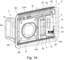
- FIGS. 1A to 4C show a first exemplary embodiment of an adjustment device V according to the invention.
- This adjustment device V has a support frame T intended for installation in a body component of a vehicle as the support structure.
- the supporting frame T can be fixed to a body part via a fastening part BF.
- the support frame T surrounds a closure opening BO, which can be closed by a closure flap K adjustably mounted on the support frame T.
- a connection area AB bordered by the support frame T is accessible via the closure opening BO when the closure flap K is open.
- a connection socket A is provided on this connection area AB as a connection element for connecting a line.
- the connection socket A serves, for example, to plug in a charging cable.
- the battery of an electric vehicle can thus be charged via the connection socket A, for example.
- the closure flap K can be adjusted externally by means of a drive 3, specifically in the installed state as intended, essentially laterally backwards (or forwards) in relation to a longitudinal axis of the vehicle.
- An adjustment movement of the closure flap K for opening and closing is carried out via a motor 31 of the Drive 3 controlled.
- the motor 31 drives a lever system 2 via a toothed gear mechanism, which transmits an adjustment movement to the closing flap K.
- the gear train is formed by a first gear element in the form of a drive worm 33' driven by the motor 31 and a second gear element in the form of a gear 201' meshing therewith.
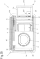
- the support frame T has a partition ST, which separates two spaces within the support frame T transversely to the direction in which the pivot axes S1 and S2 extend.
- the connection area AB with the connection socket A is arranged in a first space.
- the drive 3 is completely accommodated with the drive motor 31 and the gear train, and a receptacle L is formed.
- an adjustment bracket 21 of the adjustment device is completely accommodated.
- This adjustment bracket is formed by two pivoting levers 2a and 2b of the lever system 2, which are rigidly connected to one another by a connecting piece 210 at their protruding (upper) lever ends.
- the adjustment bracket 21, which is thus U-shaped, is held in a form-fitting manner on an inner side of the closure flap K via the connecting piece 210 and is connected to the closure flap K in an articulated manner.
- a bearing part 22 is formed between the two other (lower) ends of the pivoting levers 2a and 2b of the adjustment bracket 21 which are articulated on the support frame T.
- This bearing part 22, preferably made of plastic, is used to mount the gear wheel 201' as the second gear element of a gear train of the drive 3.
- This gear wheel 201' is non-rotatably connected to the bearing part 22 via bearing pins 20', which protrude on opposite end faces of the gear wheel 201' arranged. In this way, a rotation of the gearwheel 201' leads to the pivoting of the adjusting bracket 21 and its two pivoting levers 2a and 2b about the pivoting axis S1.
- a first gear element in the form of a drive worm 33' of the drive 3 is provided for rotating the gear 201'.
- This drive worm 33' meshes with the gear wheel 201' in order to open and close the shutter K.
- the lever system 2 has a single further one in addition to the adjustment bracket 21 with the two pivot levers 2a and 2b Pivoting lever 2c on. This cannot be driven directly by the drive motor 31, but is articulated about a second pivot axis S2 on the support frame T and on the closure flap K and is tracked only when the closure flap K is adjusted.
- the closure flap K is locked against tilting about the pivot axis S1 via the further individual pivoting lever 2c, which defines a further bearing point for the closure flap K.
- the single pivoted lever 2c is designed as an angle lever.
- the mounting of the individual pivoted lever 2c takes place on the support frame T behind a paneling part that faces the inside of the closed closure flap K.
- a through-opening in the form of a bearing slot 4 running longitudinally is provided in this covering part.
- the individual pivoted lever 2c is guided transversely to its pivot axis S2, in that its lever end 210c, which is articulated to the closing flap K, is inserted through the bearing slot 4.
- the bearing slot 4 runs in the intended installed state of the adjustment direction V essentially parallel to the longitudinal axis of the vehicle.
- a housing part 5 is provided within the support frame T and in particular within the space separated from the connection socket A by the partition ST. This housing part 5 is encompassed by the adjusting bracket 21 when it corresponds to the Figures 1A and 2A is pivoted, so the closure flap K is in a closed position.
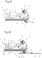
- the closure flap K is in the adjustment V of Figures 1A to 4C connected to the lever system 2 in such a way that in a maximum open position of the closure flap K, this still at least partially covers the space with the housing part 5 and only makes a viewing area with the connection socket A accessible. In its open position according to the Figure 3B the closure flap K consequently covers in particular the adjusting bracket 21 and the bearing part 22 completely, as well as the individual pivoting lever 2c.
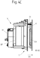
- a flat or circumferential sealing element DA is provided on the underside of the closing flap K. This sealing element DA is pressed against the connection socket A via the lever mechanism 2, when the shutter K is closed. This is in particular based on the Figures 4A to 4C illustrated in more detail.
- a control element can be provided on or inside the vehicle and/or on a remote control.
- a control element is provided (possibly additionally) directly in the area of the accessible connection socket A.
- this operating element is equipped with a sensor element SE, via which an operating event triggered by a user can be detected.
- the sensor element SE is part of a capacitive detection device in order to detect a movement performed by a finger or a hand of a user as a permissible operating event without contact.
- the actuating device V has two sensor devices 1a and 1b for opening the closing flap K by means of a gesture performed by a user.
- the sensor devices 1a and 1b each include at least one (sensor) electrode in order to capacitively detect a hand movement performed in front of the closed closure flap K, in particular a swiping movement, as an operating event for opening the closure flap K.
- the sensor devices 1a and 1b each have a printed circuit board for making electrical contact with a voltage supply and an electronic control unit for controlling the drive 3 . Electrodes of the control devices 1a and 1b can, for example, each be formed by means of a stamped grid and embedded in the (plastic) material of the support structure T.
- the two sensor devices 1a and 1b are arranged on opposite sides of the connection socket A, so that a wiping movement across the connection socket A can be reliably detected by means of the two sensor devices 1a and 1b.
- the one (second) sensor device 1b is arranged on the housing part 5, which protrudes in the receptacle L in the direction of the closing flap K.
- the installation space available on the side - here on the right - of the connection socket A can be used optimally, on the one hand to retract the adjustment bracket 21 in the closed position of the closure flap K and to stow it compactly and on the other hand to record a non-contact detection of an operating event in the area of the adjustment bracket 21.
- an operating event can be detected almost optimally without contact by changing capacitance values, in particular in the case of a closure flap K made of plastic.
- z. B. made of plastic or other electrically non-conductive material cap K with an electrically conductive element, z. B. in the form of a film to be provided as a capacitive coupling element.
- the measuring field for detecting the operating event can thus be shaped and/or enlarged.
- the electrically conductive element can be embedded in the closure flap, for example.
- the sensor devices 1a and 1b are covered with a panel section B for an aesthetically pleasing design of the area of the adjustment device V that can be seen when the closure flap K is open, in particular around the connection socket A.
- the panel section B covers the sensor devices 1a to the left of the connection socket A, the sensor device 1b and the top of the housing part 5 to the right of the connection socket A, as well as an edge surrounding the connection socket A, so that a uniform, flat surface is provided over this.
- the screen section B can be formed here by injection-moulded plastic material or a screen that is subsequently fastened.
- the sensor devices 1a and 1b which are spatially spaced apart from one another, can each be configured with one electrode or a plurality of, preferably two, electrodes and are provided for different functions.
- a gesture that is performed in front of the closed closure flap K can be detected as an operating event for opening the closure flap K via the sensor devices 1a and 1b.
- When closing the closure flap K is also on the sensor devices 1a and 1b or their electrodes and by means of in the Figure 3A Schematically illustrated electronic control unit 7, a possible obstacle in the adjustment path of the closing flap K can be detected.
- the opening of the closure flap K is measured in absolute terms by the sensor devices 1a and 1b in order to determine whether a capacitance value (increased compared to a basic capacitance) exceeds a threshold value and a hand of a user has thus approached the closure flap K and is performing a swiping movement when the closure flap K is closed, the measured values recorded by means of the sensor devices 1a and 1b are compared with empirical values serving as references. If the measured values deviate from the expected values stored in a memory of the electronic control unit 7 by more than a permissible amount, a possible obstacle in the adjustment path is indicated Closure flap K and in particular closed between an inside of the closure flap K and the vehicle body, which can be pinched by the closing flap K. In such a case, the adjustment movement of the closure flap K is automatically stopped or reversed.
- the electronic control unit 7 is coupled to the drive 3 for this purpose.
- the expected values used when the closing flap K is closed have been stored, for example, by way of a calibration when the open closing flap K is moved into its closed position (or open position) without any obstacles. An expected value is thus stored in each case for different adjustment positions of the closure flap K relative to the supporting structure T. If necessary, several obstacle-free adjustments can also be used in order to store several expected values in a position-resolved manner. If several unobstructed adjustment cycles are used, an expected value can be formed and stored, for example, by a mean value of recorded measured values.
- an adaptive adjustment of the stored expected values provision can be made for the expected values to be automatically adjusted after a stored number of adjustment cycles without obstacles, in order to take account of any signs of wear or changed environmental influences.
- the risk of false triggering of an anti-trapping device, which is (also) defined by the sensor devices 1a and 1b, can thus be reduced.
- FIG. 3A , 3B and 4B How based on Figures 3A , 3B and 4B is illustrated, it can also be provided in one embodiment to arrange (additional) electrodes 11, 12, 13 and 14 on the closure flap K itself, by means of which a gesture for opening and/or closing the closure flap K can be detected.
- the present four electrodes 11, 12 and 13, 14 arranged in pairs can be provided here instead of or in addition to the electrodes of the sensor devices 1a and 1b.
- the electrodes 11, 12, 13 and 14 are additionally provided, at least one gesture to open the closed closure flap K is detected with these.
- the (outer) electrodes 11, 12, 13 and 14 on the closure flap K serve as shielding electrodes to the outside for the (inner) electrodes of the sensor devices 1a and 1b, via which a possible obstacle in the adjustment path of the closing closure flap K should be detected.
- the electrodes 11, 12, 13 and 14 of the closure flap K are thus each operated differently depending on the direction of adjustment of the shutter K. There is a switchover from a detection function to a shielding function and vice versa, depending on whether the closure flap K is closed or should be closed.
- both pairs of electrodes 11, 12 and 13, 14 use stored threshold values to evaluate whether a user is swiping one hand from left to right to open the closure flap K across the closure flap K, which is then recorded as an operating event Triggering the opening of the shutter K is rated.
- the peripheral electrodes 11 and 14 are operated as shielding electrodes, while the inner electrodes 12 and 13 are used during the closing of the closure flap K to detect a possible case of pinching.
- All four electrodes 11, 12, 13 and 14 are therefore also part of an anti-trap device.
- only measured values recorded by the internal electrodes 12 and 13 are compared with stored expected values in order to conclude that there is a possible case of pinching in the event of an impermissibly large deviation from one or more expected values and to stop or reverse an adjustment of the closing flap K.
- the adjustment device V can not only be opened and, if necessary, closed under gesture control, but that a capacitive anti-trap device is also provided, which is at least partially provided via the same electrodes that are also used for gesture recognition.
- this sleep mode only one electrode is used to monitor whether an object is approaching the closed shutter K. If a measured value recorded using this electrode exceeds a stored threshold value, the electronic control unit 7 activated.
- the control unit 7 switches to an operating mode in which the occurrence of a gesture in the vicinity of the closed closure flap K is monitored with the at least one additional electrode, for example one of the sensor devices 1a, 1b or the electrodes 11 to 14, in order to open the release shutter K.
- a variant not shown in the figures also provides for the arrangement of electrodes on the closure flap K in such a way that at least one electrode is arranged closer to an inside and at least one electrode is arranged closer to an outside of the closure flap K.
- An (inner) electrode then serves as shielding when the closure flap K is closed and when it is opened, while the other (outer) electrode is used to detect an operating event and, if necessary, to detect an obstacle in the adjustment path of the opening closure flap K.
- the at least one (outer) electrode is used for shielding, while the other (inner) electrode takes on a measuring function and, as part of the anti-trapping device, monitors the occurrence of a potential obstacle in the adjustment path of the closing closing flap K .
- the individual electrodes can each measure against ground (or a reference potential).
- the electrodes can be arranged one above the other on or in the closure flap K in a sandwich construction.
- a 2-electrode principle can be implemented for opening (closing) and a one-electrode principle for closing (opening).
- a 2-electrode principle a changing capacitance is measured via a transmitter electrode and a receiver electrode, which usually decreases when an object approaches the closure flap K.
- a capacitance is measured against ground (or a reference potential), with a measured capacitance increasing when an object approaches.
- a display element AZ is provided (see in particular Figures 1A to 2B ), which is protected by a translucent cover AD when installed as intended.
- This display element AZ can, for example, be a light bar with one or more LEDs include. Further details for a possible operation of the display element AZ are in this case explained below Figures 5A to 5D shown.
- the pivot axis S1 and S2 of the lever mechanism 2 in the Figures 1A to 4C illustrated embodiment are provided eccentrically and in an area near the edge of the closure opening BO.
- the closure flap K can be adjusted in such a way that when it is opened, it is primarily lifted off the connection socket A along a first spatial direction R1 and, in a superimposed adjustment movement, essentially along a second direction perpendicular thereto running spatial direction R2 relative to the vehicle longitudinal axis is shifted to the rear.
- the closure flap K In an open position, the closure flap K is then at a comparatively small distance from an adjacent body outer skin and consequently takes up relatively little space in the open state.
- the closure flap K is consequently moved forward as far as possible during the adjustment between the closed position and the open position and is thus at a maximum distance along the spatial direction R1 running transversely to the pivot axis S1 or S2 from the connection socket A and the outer body skin surrounding the support frame T , but not in the fully open position.
- the inventively designed adjustment devices V with the lever mechanism 2 are comparatively compact and therefore take up little space on the body of the vehicle.
- a closure opening BO on the body can be easily closed in a sealing manner in that the closure flap K can be pulled into or against a sealing seat using the lever mechanism 2 with a sufficiently high force.
- the adjustment devices V shown are preferably designed as a prefabricated adjustment module in which the drive 3 and the lever system 2 are already functionally arranged on the support frame T to be inserted into a body opening. If necessary, the closure flap K can also already be mounted on a prefabricated, functional adjustment module with the support frame T, the drive 3 and the lever mechanism 2 . If a sensor system is provided for detecting an operating event on the adjustment device V and/or if a display element AZ is provided on the adjustment device V, the respective element is preferably also already fully functionally pre-assembled on the adjustment module in order to provide a pre-testable assembly that only needs to be to assemble the body part and with a power supply and possibly a higher-level control electronics is to be coupled.
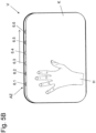
- FIG. 5A to 5D A possible control of the display element AZ is illustrated in order to give a user a visual indication of how he has to move his hand H in front of the closed closure flap K via several light sources of the display element AZ, here in the form of individual LEDs 6.1 to 6.6 to detect an operating event for opening the shutter K without contact via a capacitive detection device (with the sensor element SE).
- the individual LEDs 6.1 to 6.6 are arranged here in a row one behind the other and on a (here upper) edge area of the closure opening BO, so that light emitted by the LEDs 6.1 to 6.6 is visible even when the closure flap K is closed.
- a swiping movement which a user executes with his hand H in front of the closed closure flap K from left to right, is evaluated as a permissible operating event for opening via the capacitive detection device.
- the gesture performed with the hand H is reminiscent of a pushing movement, but the hand H does not touch the closing flap K.
- the individual LEDs 6.1 to 6.6 light up one after the other. The visual impression of a "running light" is created on the edge of the closing flap K.
- closure flap open is displayed via the display element AZ, for example by all LEDs 6.1 to 6.6 lighting up together for a specific time (e.g. 3, 4 or 5 seconds), in particular in a predetermined light color , for example white.
- a visual signal representative of this is also generated beforehand via the LEDs 6.1 to 6.6, for example in which the individual LEDs 6.1 to 6.6 flash briefly and/or synchronously.
- the display element AZ is presently designed in such a way and controlled via display electronics that charging progress when a charging plug is plugged into the connection socket A is also displayed visually for a user.
- a growth of a color-changing bar is visualized during charging via the light bar of the display element AZ defined by the LEDs 6.1 to 6.6.
- the LEDs 6.1 to 6.6 For example, if the battery is empty, only one LED 6.1 at the end of the light bar lights up red. When the battery is charged via a connected charging plug, this LED 6.1 and an adjacent LED 6.2 light up red after a while, and then three adjacent LEDs 6.1, 6.2 and 6.3 light up red. If the vehicle battery continues to be charged, four LEDs 6.1 to 6.4 light up in series and then additional LEDs in orange. If the battery is almost or fully charged, almost and then all LEDs 6.1 to 6.6 light up green. After the charging process has been completed and a charging plug has been unplugged from the connection socket A, this is also acknowledged visually via the display element AZ.
- the display element AZ on the adjusting device V is used not only to inform the user about an operating state of the adjusting device V and the level of a battery in the vehicle, but also to give the user a visual indication of the hand movement to be carried out to adjust the closing flap to display K.
- Closing of the closure flap K is triggered by touching or pressing the additionally provided sensor element SE.
- the (inner) electrodes of the sensor devices 1a and 1b as part of a Anti-trapping device operated in order to detect a possible obstacle in the adjustment path of the closing flap K and to automatically stop or reverse the adjustment movement of the closure flap K before a trapping event occurs.
- the (outer) electrodes 11, 12, 13, 14 provided on the closure flap K are then operated for shielding purposes so that objects present on the outside of the closure flap K are not detected as possible obstacles.
Landscapes
- Engineering & Computer Science (AREA)
- Life Sciences & Earth Sciences (AREA)
- Sustainable Development (AREA)
- Sustainable Energy (AREA)
- Chemical & Material Sciences (AREA)
- Combustion & Propulsion (AREA)
- Transportation (AREA)
- Mechanical Engineering (AREA)
- Power-Operated Mechanisms For Wings (AREA)
- Cooling, Air Intake And Gas Exhaust, And Fuel Tank Arrangements In Propulsion Units (AREA)
- Electric Propulsion And Braking For Vehicles (AREA)
- Operating, Guiding And Securing Of Roll- Type Closing Members (AREA)
Applications Claiming Priority (2)
| Application Number | Priority Date | Filing Date | Title |
|---|---|---|---|
| DE102016202215.6A DE102016202215A1 (de) | 2016-02-12 | 2016-02-12 | Verstellvorrichtung mit einer fremdkraftbetätigt verstellbaren Verschlussklappe |
| PCT/EP2017/050685 WO2017137210A1 (de) | 2016-02-12 | 2017-01-13 | Verstellvorrichtung mit einer fremdkraftbetätigt und berührungslos verstellbaren verschlussklappe |
Publications (3)
| Publication Number | Publication Date |
|---|---|
| EP3414123A1 EP3414123A1 (de) | 2018-12-19 |
| EP3414123C0 EP3414123C0 (de) | 2023-06-07 |
| EP3414123B1 true EP3414123B1 (de) | 2023-06-07 |
Family
ID=57882061
Family Applications (1)
| Application Number | Title | Priority Date | Filing Date |
|---|---|---|---|
| EP17701282.0A Active EP3414123B1 (de) | 2016-02-12 | 2017-01-13 | Verstellvorrichtung mit einer fremdkraftbetätigt und berührungslos verstellbaren verschlussklappe |
Country Status (7)
| Country | Link |
|---|---|
| US (1) | US11318833B2 (enExample) |
| EP (1) | EP3414123B1 (enExample) |
| JP (1) | JP6902556B2 (enExample) |
| KR (1) | KR102629787B1 (enExample) |
| CN (1) | CN108778815B (enExample) |
| DE (1) | DE102016202215A1 (enExample) |
| WO (1) | WO2017137210A1 (enExample) |
Families Citing this family (11)
| Publication number | Priority date | Publication date | Assignee | Title |
|---|---|---|---|---|
| KR102690900B1 (ko) * | 2017-02-08 | 2024-08-02 | 엘지이노텍 주식회사 | 전기 자동차의 충전을 위한 충전 제어 장치 |
| DE102017123210A1 (de) * | 2017-10-06 | 2019-04-11 | Kiekert Ag | Elektromotorischer Antrieb für kraftfahrzeugtechnische Anwendungen |
| JP6704025B2 (ja) * | 2018-09-27 | 2020-06-03 | 本田技研工業株式会社 | 車体前部構造 |
| US11456554B2 (en) | 2020-07-23 | 2022-09-27 | Caterpillar Underground Mining Pty. Ltd. | Cover assembly for charging port of electric machines |
| CN113086025B (zh) * | 2021-04-26 | 2022-04-15 | 长春捷翼汽车零部件有限公司 | 一种电动汽车的充电盖控制方法、设备及电动汽车 |
| IT202100020651A1 (it) * | 2021-07-30 | 2023-01-30 | Cebi Italy Spa | Modulo portello motorizzato per veicolo. |
| DE102021210405A1 (de) * | 2021-08-06 | 2023-02-09 | Bos Gmbh & Co. Kg | Energiezufuhranschluss zur Anordnung im Bereich einer Außenkontur eines Elektrokraftfahrzeugs und Elektrokraftfahrzeug |
| JP7528893B2 (ja) * | 2021-09-01 | 2024-08-06 | トヨタ自動車株式会社 | 電動車両 |
| CN117087770A (zh) * | 2022-05-20 | 2023-11-21 | 维特汽车有限责任公司 | 具有用于车辆上开口的襟翼单元的车辆 |
| DE102023208307A1 (de) * | 2023-08-30 | 2025-03-06 | Vitesco Technologies GmbH | Verfahren, Steuerungsvorrichtung, Steuereinheit, Fahrzeug, Computerprogramm sowie computerlesbares Medium zum Steuern eines Öffnungs- oder Schließvorgangs einer Klappe eines Fahrzeugs |
| GB2636409A (en) * | 2023-12-13 | 2025-06-18 | Jaguar Land Rover Ltd | A charging socket assembly for a traction battery of a vehicle |
Citations (1)
| Publication number | Priority date | Publication date | Assignee | Title |
|---|---|---|---|---|
| WO2015114154A2 (de) * | 2014-02-03 | 2015-08-06 | Brose Fahrzeugteile Gmbh & Co. Kg, Coburg | Verschlussvorrichtung für eine befüllungs- oder anschlussöffnung an einem fahrzeug |
Family Cites Families (71)
| Publication number | Priority date | Publication date | Assignee | Title |
|---|---|---|---|---|
| DE1983291U (de) | 1967-11-21 | 1968-04-11 | Rodenstock Optik G | Fixationseinrichtung an ophthalmometern. |
| FR2538786A1 (fr) | 1983-01-05 | 1984-07-06 | Neiman Diffusion | Dispositif de fermeture d'un embout de reservoir de vehicule automobile |
| DE3301072C3 (de) | 1983-01-14 | 1997-11-20 | Itw Ateco Gmbh | Tankmulde für Kraftfahrzeuge |
| DE3637289A1 (de) | 1986-11-03 | 1988-05-11 | Bayerische Motoren Werke Ag | Verschluss in kraftfahrzeugen |
| IT1212155B (it) | 1987-12-29 | 1989-11-08 | Fiat Auto Spa | Bocchettone carburante con dispositivo di chiusura di tipo perfezionato comandabile dall interno di un veicolo |
| US4886182A (en) | 1989-05-26 | 1989-12-12 | Chrysler Motors Corporation | Fuel filler assembly |
| FR2704299B1 (fr) | 1993-04-22 | 1995-06-02 | Journee Paul Sa | Agencement pour l'obturation d'une canalisation de remplissage d'un réservoir de carburant de véhicule automobile. |
| JPH06349544A (ja) | 1993-06-14 | 1994-12-22 | Sumitomo Wiring Syst Ltd | 車両用充電コネクタ構造 |
| EP0704331A1 (en) | 1994-09-28 | 1996-04-03 | Bing-Jye Cherng | A power gas tank cover |
| DE4438610A1 (de) | 1994-10-28 | 1996-05-02 | Bayerische Motoren Werke Ag | Verstellbare Klappe, insbesondere Tankklappe eines Kraftfahrzeugs |
| DE4440814A1 (de) | 1994-11-15 | 1996-05-23 | Bayerische Motoren Werke Ag | Verschiebbare Klappe, insbesondere Tankklappe eines Kraftfahrzeugs |
| DE19535335C2 (de) | 1995-09-22 | 1999-10-28 | Webasto Karosseriesysteme | Tankverschlußsystem |
| FR2765837B1 (fr) | 1997-07-09 | 1999-10-08 | Journee Paul Sa | Dispositif de remplissage d'un reservoir de carburant de vehicule automobile comportant un bol de fixation venu de matiere avec une tete de remplissage |
| DE19832910C2 (de) | 1997-07-25 | 2003-03-27 | Alfmeier Praez Ag | Verschlußvorrichtung für Kraftfahrzeugtanks |
| US5901760A (en) | 1997-12-12 | 1999-05-11 | Illinois Tool Works Inc. | Automotive fuel filler pipe ball valve assembly |
| DE19919251A1 (de) | 1999-04-28 | 2000-11-02 | Bayerische Motoren Werke Ag | Verschlußeinrichtung für einen Kraftstoffbehälter eines Kraftfahrzeuges |
| DE19935454C2 (de) | 1999-07-28 | 2001-05-31 | Alfmeier Praez Ag | Vorrichtung zum automatischen Öffnen und Schließen des Tankdeckels und der Tankklappe eines Kraftfahrzeuges |
| DE29921802U1 (de) | 1999-12-10 | 2000-03-02 | Hermann Vogt GmbH & Co, 72764 Reutlingen | Scharnierfeder für eine Tankklappe eines Kraftfahrzeugs |
| FR2817511B1 (fr) | 2000-12-06 | 2003-03-21 | Neyr Plastiques Holding | Dispositif de fermeture de reservoir de vehicule automobile |
| JP5150810B2 (ja) | 2001-03-23 | 2013-02-27 | オプテックス株式会社 | 自動ドアの開閉制御装置 |
| DE10117536A1 (de) | 2001-04-07 | 2002-10-10 | Gossler Fluidtec Gmbh | Vorrichtung zum Verschließen eines Fahrzeugtanks |
| DE10145531A1 (de) | 2001-09-14 | 2003-04-03 | Audi Ag | Tankverschluss für ein Kraftfahrzeug |
| DE10153724A1 (de) | 2001-10-31 | 2003-05-15 | Raufoss Germany Gmbh | Fahrzeugklappe |
| US7080671B2 (en) | 2002-12-17 | 2006-07-25 | Paraphase, Inc. | Replacement vehicle fuel intake device |
| DE602004014207D1 (de) | 2003-01-24 | 2008-07-17 | Ford Global Tech Llc | System zum Einfüllen von Kraftstoff |
| JP4576837B2 (ja) | 2003-02-12 | 2010-11-10 | 日産自動車株式会社 | 車両用開閉体作動装置 |
| DE10315513A1 (de) | 2003-04-04 | 2004-10-28 | Temtec Fahrzeugtechnik Entwicklungsgesellschaft Mbh | Kraftstoffbehälterverschluss |
| ES2294905A1 (es) | 2005-11-14 | 2008-04-01 | Maier, S. Coop. | Conjunto de tapa. |
| JP4207964B2 (ja) | 2006-01-27 | 2009-01-14 | トヨタ自動車株式会社 | 車両のガス燃料充填蓋装置 |
| DE102006042447A1 (de) | 2006-05-06 | 2007-11-08 | Bayerische Motoren Werke Ag | Kraftfahrzeug mit einer schwenkbar gelagerten Tankklappe |
| JP4991318B2 (ja) | 2007-01-10 | 2012-08-01 | 株式会社ニフコ | 給油口の開閉装置 |
| FR2915144B1 (fr) | 2007-04-18 | 2009-05-22 | Coutier Moulage Gen Ind | Trappe a carburant motorisee pour vehicule automobile. |
| US7900986B2 (en) | 2007-08-31 | 2011-03-08 | Gm Global Technology Operations, Inc. | Active material based concealment assemblies |
| JP2009073432A (ja) * | 2007-09-24 | 2009-04-09 | Denso Corp | 車両用給油口開閉機構 |
| JP5142662B2 (ja) | 2007-10-22 | 2013-02-13 | 本田技研工業株式会社 | 自動二輪車の物入れ構造 |
| FR2940772A1 (fr) | 2009-01-05 | 2010-07-09 | Peugeot Citroen Automobiles Sa | Trappe a carburant pour vehicule pourvu d'un systeme d'acces mains libres |
| DE102009023594A1 (de) | 2009-06-02 | 2010-12-09 | Volkswagen Ag | Verfahren und Vorrichtung zur Betätigung eines Schließelements eines Fahrzeugs |
| US8439421B2 (en) | 2009-12-16 | 2013-05-14 | Honda Motor Co., Ltd. | Fuel lid |
| DE102009058864B4 (de) | 2009-12-18 | 2012-05-10 | Temtec Fahrzeugtechnik Entwicklungsgesellschaft Mbh | Verfahren zum Ansteuern eines Kraftfahrzeugverschlusses und Verschlusseinrichtung für Kraftfahrzeuge |
| JP5460464B2 (ja) | 2010-05-24 | 2014-04-02 | 株式会社城南製作所 | 蓋の開閉リンク構造 |
| KR20130129073A (ko) | 2010-05-28 | 2013-11-27 | 키커트 악티엔게젤샤프트 | 자동차용 액추에이터 |
| JP5488355B2 (ja) | 2010-09-03 | 2014-05-14 | 三菱自動車工業株式会社 | リッドの開閉機構 |
| DE102010049400A1 (de) | 2010-10-26 | 2012-04-26 | Brose Fahrzeugteile Gmbh & Co. Kommanditgesellschaft, Hallstadt | Sensoreinheit zum berührungslosen Betätigen einer Fahrzeugtür |
| DE102010060364A1 (de) * | 2010-11-04 | 2012-05-10 | Huf Hülsbeck & Fürst Gmbh & Co. Kg | Verfahren für ein Kraftfahrzeug |
| JP5398920B2 (ja) * | 2010-12-24 | 2014-01-29 | 株式会社リブ技術研究所 | 開閉部の挟み込み判定装置、その装置を備えた車両および開閉部の挟み込み判定方法 |
| JP5382050B2 (ja) | 2011-04-06 | 2014-01-08 | アイシン精機株式会社 | 車両用開閉体作動装置 |
| DE102011111234A1 (de) | 2011-08-20 | 2013-02-21 | GM Global Technology Operations LLC (n. d. Gesetzen des Staates Delaware) | Anzeigevorrichtung |
| DE102011112684A1 (de) * | 2011-09-07 | 2013-03-07 | GM Global Technology Operations LLC (n. d. Ges. d. Staates Delaware) | Kraftfahrzeug mit einer Heckklappe |
| JP2013057181A (ja) | 2011-09-07 | 2013-03-28 | Alps Electric Co Ltd | 自動車の扉体用ラッチ解除装置 |
| FR2979873B1 (fr) * | 2011-09-12 | 2013-10-04 | Valeo Securite Habitacle | Procede d'ouverture d'un ouvrant de vehicule automobile |
| DE102011114383A1 (de) | 2011-09-24 | 2013-03-28 | Kiekert Ag | Verriegelung für den Ladeanschluss eines Kraftfahrzeugs |
| US8539990B2 (en) | 2011-09-28 | 2013-09-24 | Tesla Motors, Inc. | Vehicle port door with wirelessly actuated unlatching assembly |
| DE102012009018B4 (de) | 2012-05-05 | 2025-01-02 | Volkswagen Aktiengesellschaft | Schwenkbar gelagerte Klappe an einem Fahrzeug sowie Fahrzeug |
| DE102012107116A1 (de) | 2012-08-02 | 2014-02-06 | Brose Fahrzeugteile Gmbh & Co. Kommanditgesellschaft, Hallstadt | Verfahren zur Steuerung einer Verstellbewegung eines Fahrzeugschließelements mit Kollisionsvermeidung für einen Schlossbereich und Einklemmschutzsystem |
| DE102012107115A1 (de) | 2012-08-02 | 2014-02-06 | Brose Fahrzeugteile Gmbh & Co. Kommanditgesellschaft, Hallstadt | Verfahren zur Steuerung eines kapazitiven Einklemmschutzsystems und Einklemmschutzsystem |
| DE202012007455U1 (de) | 2012-08-02 | 2013-11-05 | Brose Fahrzeugteile Gmbh & Co. Kommanditgesellschaft, Hallstadt | Stellvorrichtung für ein bewegbares Fahrzeugteil |
| DE102012110383A1 (de) * | 2012-10-30 | 2014-04-30 | Brose Fahrzeugteile Gmbh & Co. Kommanditgesellschaft, Hallstadt | System zur fremdkraftbetätigten Verstelllung eines Fahrzeugschließelements mit Kopplung mit einem Fahrzeugsensor und Verwendung eines Fahrzeugsensors |
| DE102012021518A1 (de) | 2012-11-02 | 2014-05-08 | Volkswagen Aktiengesellschaft | Verfahren zur Unterstützung eines Betankungs-/Aufladevorgangs eines Energiespeichers eines Fahrzeugs |
| JP6108161B2 (ja) * | 2013-03-15 | 2017-04-05 | アイシン精機株式会社 | 報知音量制御装置及び開閉体装置 |
| DE102013005063A1 (de) | 2013-03-22 | 2014-09-25 | Brose Fahrzeugteile Gmbh & Co. Kommanditgesellschaft, Hallstadt | Einklemmschutz für ein verstellbares Fahrzeugteil |
| JP5965349B2 (ja) | 2013-04-17 | 2016-08-03 | 株式会社城南製作所 | 自動車のエネルギー受給口装置 |
| JP5937542B2 (ja) * | 2013-05-15 | 2016-06-22 | 株式会社城南製作所 | 車両用カバー開閉制御装置 |
| DE102013010993A1 (de) * | 2013-07-02 | 2015-01-08 | Brose Fahrzeugteile Gmbh & Co. Kommanditgesellschaft, Hallstadt | Objekterfassungsvorrichtung für ein Fahrzeug |
| US9475369B2 (en) * | 2013-07-17 | 2016-10-25 | Aisin Seiki Kabushiki Kaisha | Vehicle door opening and closing apparatus and method of controlling the same |
| DE102013215815C5 (de) * | 2013-08-09 | 2021-09-16 | Ifm Electronic Gmbh | Anordnung zur Steuerung einer automatisch öffnenden Seitenschiebetür |
| US9327594B2 (en) | 2013-08-15 | 2016-05-03 | GM Global Technology Operations LLC | Access system for vehicle energy storage device with magnetic sensor to detect access door position |
| DE102013018628A1 (de) * | 2013-11-06 | 2015-05-07 | Brose Fahrzeugteile Gmbh & Co. Kommanditgesellschaft, Hallstadt | Einklemmschutz für eine verstellbare Fahrzeugtür |
| DE102014100580A1 (de) * | 2014-01-20 | 2015-07-23 | Huf Hülsbeck & Fürst Gmbh & Co. Kg | Vorrichtung zum berührungslosen Betätigen einer Schiebetür eines Kraftfahrzeuges |
| US9669708B2 (en) | 2014-01-31 | 2017-06-06 | Mark Steven Dunger | Retractable vehicle fueling receptacle cover |
| KR101575498B1 (ko) | 2014-06-25 | 2015-12-07 | 기아자동차주식회사 | 전기자동차의 충전포트 도어 개폐장치 |
| DE102014117896A1 (de) * | 2014-12-04 | 2016-06-23 | Brose Fahrzeugteile Gmbh & Co. Kg, Hallstadt | Verfahren zur Ansteuerung einer Schiebetüranordnung eines Kraftfahrzeugs |
-
2016
- 2016-02-12 DE DE102016202215.6A patent/DE102016202215A1/de not_active Withdrawn
-
2017
- 2017-01-13 KR KR1020187024284A patent/KR102629787B1/ko active Active
- 2017-01-13 WO PCT/EP2017/050685 patent/WO2017137210A1/de not_active Ceased
- 2017-01-13 US US16/070,508 patent/US11318833B2/en active Active
- 2017-01-13 CN CN201780011222.5A patent/CN108778815B/zh active Active
- 2017-01-13 JP JP2018542175A patent/JP6902556B2/ja active Active
- 2017-01-13 EP EP17701282.0A patent/EP3414123B1/de active Active
Patent Citations (1)
| Publication number | Priority date | Publication date | Assignee | Title |
|---|---|---|---|---|
| WO2015114154A2 (de) * | 2014-02-03 | 2015-08-06 | Brose Fahrzeugteile Gmbh & Co. Kg, Coburg | Verschlussvorrichtung für eine befüllungs- oder anschlussöffnung an einem fahrzeug |
Also Published As
| Publication number | Publication date |
|---|---|
| WO2017137210A1 (de) | 2017-08-17 |
| US11318833B2 (en) | 2022-05-03 |
| JP2019507700A (ja) | 2019-03-22 |
| EP3414123C0 (de) | 2023-06-07 |
| DE102016202215A1 (de) | 2017-08-17 |
| EP3414123A1 (de) | 2018-12-19 |
| KR102629787B1 (ko) | 2024-01-25 |
| US20210213828A1 (en) | 2021-07-15 |
| CN108778815B (zh) | 2021-12-31 |
| JP6902556B2 (ja) | 2021-07-14 |
| CN108778815A (zh) | 2018-11-09 |
| KR20180111861A (ko) | 2018-10-11 |
Similar Documents
| Publication | Publication Date | Title |
|---|---|---|
| EP3414123B1 (de) | Verstellvorrichtung mit einer fremdkraftbetätigt und berührungslos verstellbaren verschlussklappe | |
| DE102016202214A1 (de) | Verstellvorrichtung mit einer fremdkraftbetätigt verstellbaren Verschlussklappe | |
| DE102018122443A1 (de) | Kapazitives Feld mit mechanischem Notfallschalter für ein elektronisches Fahrzeug-Zugangssystem | |
| DE4322937A1 (de) | Informationseinrichtung in einem Kraftfahrzeug | |
| DE102010035828A1 (de) | Öffnungs- und Verschlussvorrichtung | |
| EP1992070A2 (de) | Sensoreinrichtung | |
| DE102013012489A1 (de) | Türgriffsystem für eine Fahrzeugtür | |
| DE102014103642A1 (de) | Verschlussvorrichtung für eine Befüllungs- oder Anschlussöffnung an einem Fahrzeug | |
| DE102011010906A1 (de) | Haushaltsgerät | |
| EP3198567A1 (de) | Daten- und messerfassungsvorrichtung für einen türgriff sowie verfahren dazu | |
| WO2013026546A1 (de) | Türmodul mit integrierter sensorelektrode | |
| DE102008043143B3 (de) | Schmieranlage mit integrierter Elektronik | |
| DE102014015403A1 (de) | Bedienvorrichtung zum Steuern von wenigstens einer Funktion von wenigstens einer kraftfahrzeugseitigen Einrichtung | |
| EP4556663A1 (de) | Fahrzeugtür mit einem ausfahrbaren griff | |
| DE102010054372B4 (de) | Außenspiegelanordnung mit Gleitscheibe | |
| EP3145762B1 (de) | Fahrzeugteil fuer den aussenbereich eines kraftfahrzeugs und kraftfahrzeug | |
| EP1066180B1 (de) | Scheibenwischer-antriebsaggregat und damit ausgestattetes fahrzeug | |
| DE102014202650A1 (de) | Verfahren und Vorrichtung zum Bedienen der Mechanik einer motorisch positionsveränderlichen Anzeigeeinheit | |
| DE102014010177B4 (de) | Sensormodul zur berührungslosen Betätigung eines verstellbaren Fahrzeugteils | |
| DE102018107179A1 (de) | Verfahren zur Ansteuerung einer motorischen Klappenanordnung eines Kraftfahrzeugs | |
| DE102024201795A1 (de) | Betätigungseinheit für eine Fahrzeugklappe und Fahrzeugklappe | |
| DE102013019246A1 (de) | Vorrichtung zur berührungslosen Betätigung eines Fahrzeugteils | |
| DE202008014121U1 (de) | Schmieranlage mit integrierter Elektronik |
Legal Events
| Date | Code | Title | Description |
|---|---|---|---|
| STAA | Information on the status of an ep patent application or granted ep patent |
Free format text: STATUS: UNKNOWN |
|
| STAA | Information on the status of an ep patent application or granted ep patent |
Free format text: STATUS: THE INTERNATIONAL PUBLICATION HAS BEEN MADE |
|
| PUAI | Public reference made under article 153(3) epc to a published international application that has entered the european phase |
Free format text: ORIGINAL CODE: 0009012 |
|
| STAA | Information on the status of an ep patent application or granted ep patent |
Free format text: STATUS: REQUEST FOR EXAMINATION WAS MADE |
|
| 17P | Request for examination filed |
Effective date: 20180912 |
|
| AK | Designated contracting states |
Kind code of ref document: A1 Designated state(s): AL AT BE BG CH CY CZ DE DK EE ES FI FR GB GR HR HU IE IS IT LI LT LU LV MC MK MT NL NO PL PT RO RS SE SI SK SM TR |
|
| AX | Request for extension of the european patent |
Extension state: BA ME |
|
| RIN1 | Information on inventor provided before grant (corrected) |
Inventor name: DAIMINGER, RALF Inventor name: RICHTER, STEFAN |
|
| DAV | Request for validation of the european patent (deleted) | ||
| DAX | Request for extension of the european patent (deleted) | ||
| RAP1 | Party data changed (applicant data changed or rights of an application transferred) |
Owner name: BROSE FAHRZEUGTEILE SE & CO. KOMMANDITGESELLSCHAFT, COBURG |
|
| STAA | Information on the status of an ep patent application or granted ep patent |
Free format text: STATUS: EXAMINATION IS IN PROGRESS |
|
| 17Q | First examination report despatched |
Effective date: 20200908 |
|
| GRAP | Despatch of communication of intention to grant a patent |
Free format text: ORIGINAL CODE: EPIDOSNIGR1 |
|
| STAA | Information on the status of an ep patent application or granted ep patent |
Free format text: STATUS: GRANT OF PATENT IS INTENDED |
|
| INTG | Intention to grant announced |
Effective date: 20220831 |
|
| GRAS | Grant fee paid |
Free format text: ORIGINAL CODE: EPIDOSNIGR3 |
|
| GRAA | (expected) grant |
Free format text: ORIGINAL CODE: 0009210 |
|
| STAA | Information on the status of an ep patent application or granted ep patent |
Free format text: STATUS: THE PATENT HAS BEEN GRANTED |
|
| AK | Designated contracting states |
Kind code of ref document: B1 Designated state(s): AL AT BE BG CH CY CZ DE DK EE ES FI FR GB GR HR HU IE IS IT LI LT LU LV MC MK MT NL NO PL PT RO RS SE SI SK SM TR |
|
| REG | Reference to a national code |
Ref country code: GB Ref legal event code: FG4D Free format text: NOT ENGLISH |
|
| REG | Reference to a national code |
Ref country code: CH Ref legal event code: EP Ref country code: AT Ref legal event code: REF Ref document number: 1573995 Country of ref document: AT Kind code of ref document: T Effective date: 20230615 Ref country code: DE Ref legal event code: R096 Ref document number: 502017014821 Country of ref document: DE |
|
| U01 | Request for unitary effect filed |
Effective date: 20230607 |
|
| U07 | Unitary effect registered |
Designated state(s): AT BE BG DE DK EE FI FR IT LT LU LV MT NL PT SE SI Effective date: 20230612 |
|
| REG | Reference to a national code |
Ref country code: LT Ref legal event code: MG9D |
|
| PG25 | Lapsed in a contracting state [announced via postgrant information from national office to epo] |
Ref country code: NO Free format text: LAPSE BECAUSE OF FAILURE TO SUBMIT A TRANSLATION OF THE DESCRIPTION OR TO PAY THE FEE WITHIN THE PRESCRIBED TIME-LIMIT Effective date: 20230907 Ref country code: ES Free format text: LAPSE BECAUSE OF FAILURE TO SUBMIT A TRANSLATION OF THE DESCRIPTION OR TO PAY THE FEE WITHIN THE PRESCRIBED TIME-LIMIT Effective date: 20230607 |
|
| PG25 | Lapsed in a contracting state [announced via postgrant information from national office to epo] |
Ref country code: RS Free format text: LAPSE BECAUSE OF FAILURE TO SUBMIT A TRANSLATION OF THE DESCRIPTION OR TO PAY THE FEE WITHIN THE PRESCRIBED TIME-LIMIT Effective date: 20230607 Ref country code: HR Free format text: LAPSE BECAUSE OF FAILURE TO SUBMIT A TRANSLATION OF THE DESCRIPTION OR TO PAY THE FEE WITHIN THE PRESCRIBED TIME-LIMIT Effective date: 20230607 Ref country code: GR Free format text: LAPSE BECAUSE OF FAILURE TO SUBMIT A TRANSLATION OF THE DESCRIPTION OR TO PAY THE FEE WITHIN THE PRESCRIBED TIME-LIMIT Effective date: 20230908 |
|
| PG25 | Lapsed in a contracting state [announced via postgrant information from national office to epo] |
Ref country code: SK Free format text: LAPSE BECAUSE OF FAILURE TO SUBMIT A TRANSLATION OF THE DESCRIPTION OR TO PAY THE FEE WITHIN THE PRESCRIBED TIME-LIMIT Effective date: 20230607 |
|
| PG25 | Lapsed in a contracting state [announced via postgrant information from national office to epo] |
Ref country code: IS Free format text: LAPSE BECAUSE OF FAILURE TO SUBMIT A TRANSLATION OF THE DESCRIPTION OR TO PAY THE FEE WITHIN THE PRESCRIBED TIME-LIMIT Effective date: 20231007 |
|
| PG25 | Lapsed in a contracting state [announced via postgrant information from national office to epo] |
Ref country code: SM Free format text: LAPSE BECAUSE OF FAILURE TO SUBMIT A TRANSLATION OF THE DESCRIPTION OR TO PAY THE FEE WITHIN THE PRESCRIBED TIME-LIMIT Effective date: 20230607 Ref country code: SK Free format text: LAPSE BECAUSE OF FAILURE TO SUBMIT A TRANSLATION OF THE DESCRIPTION OR TO PAY THE FEE WITHIN THE PRESCRIBED TIME-LIMIT Effective date: 20230607 Ref country code: RO Free format text: LAPSE BECAUSE OF FAILURE TO SUBMIT A TRANSLATION OF THE DESCRIPTION OR TO PAY THE FEE WITHIN THE PRESCRIBED TIME-LIMIT Effective date: 20230607 Ref country code: IS Free format text: LAPSE BECAUSE OF FAILURE TO SUBMIT A TRANSLATION OF THE DESCRIPTION OR TO PAY THE FEE WITHIN THE PRESCRIBED TIME-LIMIT Effective date: 20231007 Ref country code: CZ Free format text: LAPSE BECAUSE OF FAILURE TO SUBMIT A TRANSLATION OF THE DESCRIPTION OR TO PAY THE FEE WITHIN THE PRESCRIBED TIME-LIMIT Effective date: 20230607 |
|
| PG25 | Lapsed in a contracting state [announced via postgrant information from national office to epo] |
Ref country code: PL Free format text: LAPSE BECAUSE OF FAILURE TO SUBMIT A TRANSLATION OF THE DESCRIPTION OR TO PAY THE FEE WITHIN THE PRESCRIBED TIME-LIMIT Effective date: 20230607 |
|
| U20 | Renewal fee for the european patent with unitary effect paid |
Year of fee payment: 8 Effective date: 20240131 |
|
| REG | Reference to a national code |
Ref country code: DE Ref legal event code: R097 Ref document number: 502017014821 Country of ref document: DE |
|
| PLBE | No opposition filed within time limit |
Free format text: ORIGINAL CODE: 0009261 |
|
| STAA | Information on the status of an ep patent application or granted ep patent |
Free format text: STATUS: NO OPPOSITION FILED WITHIN TIME LIMIT |
|
| 26N | No opposition filed |
Effective date: 20240308 |
|
| PG25 | Lapsed in a contracting state [announced via postgrant information from national office to epo] |
Ref country code: MC Free format text: LAPSE BECAUSE OF FAILURE TO SUBMIT A TRANSLATION OF THE DESCRIPTION OR TO PAY THE FEE WITHIN THE PRESCRIBED TIME-LIMIT Effective date: 20230607 |
|
| PG25 | Lapsed in a contracting state [announced via postgrant information from national office to epo] |
Ref country code: MC Free format text: LAPSE BECAUSE OF FAILURE TO SUBMIT A TRANSLATION OF THE DESCRIPTION OR TO PAY THE FEE WITHIN THE PRESCRIBED TIME-LIMIT Effective date: 20230607 |
|
| REG | Reference to a national code |
Ref country code: CH Ref legal event code: PL |
|
| GBPC | Gb: european patent ceased through non-payment of renewal fee |
Effective date: 20240113 |
|
| PG25 | Lapsed in a contracting state [announced via postgrant information from national office to epo] |
Ref country code: GB Free format text: LAPSE BECAUSE OF NON-PAYMENT OF DUE FEES Effective date: 20240113 |
|
| PG25 | Lapsed in a contracting state [announced via postgrant information from national office to epo] |
Ref country code: CH Free format text: LAPSE BECAUSE OF NON-PAYMENT OF DUE FEES Effective date: 20240131 |
|
| PG25 | Lapsed in a contracting state [announced via postgrant information from national office to epo] |
Ref country code: GB Free format text: LAPSE BECAUSE OF NON-PAYMENT OF DUE FEES Effective date: 20240113 Ref country code: CH Free format text: LAPSE BECAUSE OF NON-PAYMENT OF DUE FEES Effective date: 20240131 |
|
| PG25 | Lapsed in a contracting state [announced via postgrant information from national office to epo] |
Ref country code: IE Free format text: LAPSE BECAUSE OF NON-PAYMENT OF DUE FEES Effective date: 20240113 |
|
| PG25 | Lapsed in a contracting state [announced via postgrant information from national office to epo] |
Ref country code: IE Free format text: LAPSE BECAUSE OF NON-PAYMENT OF DUE FEES Effective date: 20240113 |
|
| PG25 | Lapsed in a contracting state [announced via postgrant information from national office to epo] |
Ref country code: CY Free format text: LAPSE BECAUSE OF FAILURE TO SUBMIT A TRANSLATION OF THE DESCRIPTION OR TO PAY THE FEE WITHIN THE PRESCRIBED TIME-LIMIT; INVALID AB INITIO Effective date: 20170113 |
|
| PG25 | Lapsed in a contracting state [announced via postgrant information from national office to epo] |
Ref country code: HU Free format text: LAPSE BECAUSE OF FAILURE TO SUBMIT A TRANSLATION OF THE DESCRIPTION OR TO PAY THE FEE WITHIN THE PRESCRIBED TIME-LIMIT; INVALID AB INITIO Effective date: 20170113 |
|
| U90 | Renewal fees not paid: noting of loss of rights |
Free format text: RENEWAL FEE NOT PAID FOR YEAR 09 Effective date: 20250819 |
|
| U93 | Unitary patent lapsed |
Free format text: RENEWAL FEE NOT PAID Effective date: 20250131 |
|
| PG25 | Lapsed in a contracting state [announced via postgrant information from national office to epo] |
Ref country code: TR Free format text: LAPSE BECAUSE OF FAILURE TO SUBMIT A TRANSLATION OF THE DESCRIPTION OR TO PAY THE FEE WITHIN THE PRESCRIBED TIME-LIMIT Effective date: 20230607 |