EP3414123B1 - Adjustment mechanism comprising a closure flap adjustable in a contactless manner by an external force - Google Patents
Adjustment mechanism comprising a closure flap adjustable in a contactless manner by an external force Download PDFInfo
- Publication number
- EP3414123B1 EP3414123B1 EP17701282.0A EP17701282A EP3414123B1 EP 3414123 B1 EP3414123 B1 EP 3414123B1 EP 17701282 A EP17701282 A EP 17701282A EP 3414123 B1 EP3414123 B1 EP 3414123B1
- Authority
- EP
- European Patent Office
- Prior art keywords
- closure flap
- electrode
- opening
- adjustment
- flap
- Prior art date
- Legal status (The legal status is an assumption and is not a legal conclusion. Google has not performed a legal analysis and makes no representation as to the accuracy of the status listed.)
- Active
Links
- 230000007246 mechanism Effects 0.000 title claims description 29
- 230000033001 locomotion Effects 0.000 claims description 28
- 238000000034 method Methods 0.000 claims description 7
- 230000004044 response Effects 0.000 claims description 7
- 239000007788 liquid Substances 0.000 claims description 6
- 239000000446 fuel Substances 0.000 claims description 4
- 230000003466 anti-cipated effect Effects 0.000 claims 6
- 230000006870 function Effects 0.000 description 17
- 238000001514 detection method Methods 0.000 description 16
- 239000000463 material Substances 0.000 description 8
- 230000001965 increasing effect Effects 0.000 description 7
- 239000004033 plastic Substances 0.000 description 7
- 230000008859 change Effects 0.000 description 6
- 238000007789 sealing Methods 0.000 description 6
- 230000000007 visual effect Effects 0.000 description 6
- 238000013459 approach Methods 0.000 description 5
- 238000011161 development Methods 0.000 description 5
- 230000007613 environmental effect Effects 0.000 description 4
- 239000002828 fuel tank Substances 0.000 description 4
- 230000008093 supporting effect Effects 0.000 description 4
- 238000009434 installation Methods 0.000 description 3
- 238000005259 measurement Methods 0.000 description 3
- 238000005192 partition Methods 0.000 description 3
- 230000001960 triggered effect Effects 0.000 description 3
- RYGMFSIKBFXOCR-UHFFFAOYSA-N Copper Chemical compound [Cu] RYGMFSIKBFXOCR-UHFFFAOYSA-N 0.000 description 2
- 230000003044 adaptive effect Effects 0.000 description 2
- 239000003086 colorant Substances 0.000 description 2
- 230000007423 decrease Effects 0.000 description 2
- 230000009977 dual effect Effects 0.000 description 2
- 230000005684 electric field Effects 0.000 description 2
- 238000011156 evaluation Methods 0.000 description 2
- 230000006872 improvement Effects 0.000 description 2
- 239000002991 molded plastic Substances 0.000 description 2
- 210000002023 somite Anatomy 0.000 description 2
- 230000004308 accommodation Effects 0.000 description 1
- 230000006978 adaptation Effects 0.000 description 1
- 238000005253 cladding Methods 0.000 description 1
- 238000010276 construction Methods 0.000 description 1
- 239000002826 coolant Substances 0.000 description 1
- 229910052802 copper Inorganic materials 0.000 description 1
- 239000010949 copper Substances 0.000 description 1
- 239000011889 copper foil Substances 0.000 description 1
- 230000008878 coupling Effects 0.000 description 1
- 238000010168 coupling process Methods 0.000 description 1
- 238000005859 coupling reaction Methods 0.000 description 1
- 238000013461 design Methods 0.000 description 1
- 230000004438 eyesight Effects 0.000 description 1
- 239000012530 fluid Substances 0.000 description 1
- 239000003502 gasoline Substances 0.000 description 1
- 229910052739 hydrogen Inorganic materials 0.000 description 1
- 239000001257 hydrogen Substances 0.000 description 1
- 125000004435 hydrogen atom Chemical class [H]* 0.000 description 1
- 230000001976 improved effect Effects 0.000 description 1
- 230000001939 inductive effect Effects 0.000 description 1
- 230000007257 malfunction Effects 0.000 description 1
- 239000007769 metal material Substances 0.000 description 1
- 239000010705 motor oil Substances 0.000 description 1
- 239000012811 non-conductive material Substances 0.000 description 1
- 239000003921 oil Substances 0.000 description 1
- 230000002093 peripheral effect Effects 0.000 description 1
- 230000008569 process Effects 0.000 description 1
- 230000006641 stabilisation Effects 0.000 description 1
- 238000011105 stabilization Methods 0.000 description 1
- 230000002618 waking effect Effects 0.000 description 1
- XLYOFNOQVPJJNP-UHFFFAOYSA-N water Substances O XLYOFNOQVPJJNP-UHFFFAOYSA-N 0.000 description 1
Images


Classifications
-
- B—PERFORMING OPERATIONS; TRANSPORTING
- B60—VEHICLES IN GENERAL
- B60K—ARRANGEMENT OR MOUNTING OF PROPULSION UNITS OR OF TRANSMISSIONS IN VEHICLES; ARRANGEMENT OR MOUNTING OF PLURAL DIVERSE PRIME-MOVERS IN VEHICLES; AUXILIARY DRIVES FOR VEHICLES; INSTRUMENTATION OR DASHBOARDS FOR VEHICLES; ARRANGEMENTS IN CONNECTION WITH COOLING, AIR INTAKE, GAS EXHAUST OR FUEL SUPPLY OF PROPULSION UNITS IN VEHICLES
- B60K15/00—Arrangement in connection with fuel supply of combustion engines or other fuel consuming energy converters, e.g. fuel cells; Mounting or construction of fuel tanks
- B60K15/03—Fuel tanks
- B60K15/04—Tank inlets
- B60K15/05—Inlet covers
-
- E—FIXED CONSTRUCTIONS
- E05—LOCKS; KEYS; WINDOW OR DOOR FITTINGS; SAFES
- E05F—DEVICES FOR MOVING WINGS INTO OPEN OR CLOSED POSITION; CHECKS FOR WINGS; WING FITTINGS NOT OTHERWISE PROVIDED FOR, CONCERNED WITH THE FUNCTIONING OF THE WING
- E05F15/00—Power-operated mechanisms for wings
- E05F15/70—Power-operated mechanisms for wings with automatic actuation
- E05F15/73—Power-operated mechanisms for wings with automatic actuation responsive to movement or presence of persons or objects
-
- B—PERFORMING OPERATIONS; TRANSPORTING
- B60—VEHICLES IN GENERAL
- B60K—ARRANGEMENT OR MOUNTING OF PROPULSION UNITS OR OF TRANSMISSIONS IN VEHICLES; ARRANGEMENT OR MOUNTING OF PLURAL DIVERSE PRIME-MOVERS IN VEHICLES; AUXILIARY DRIVES FOR VEHICLES; INSTRUMENTATION OR DASHBOARDS FOR VEHICLES; ARRANGEMENTS IN CONNECTION WITH COOLING, AIR INTAKE, GAS EXHAUST OR FUEL SUPPLY OF PROPULSION UNITS IN VEHICLES
- B60K15/00—Arrangement in connection with fuel supply of combustion engines or other fuel consuming energy converters, e.g. fuel cells; Mounting or construction of fuel tanks
- B60K15/03—Fuel tanks
- B60K2015/03328—Arrangements or special measures related to fuel tanks or fuel handling
- B60K2015/03375—Arrangements or special measures related to fuel tanks or fuel handling to improve security
-
- B—PERFORMING OPERATIONS; TRANSPORTING
- B60—VEHICLES IN GENERAL
- B60K—ARRANGEMENT OR MOUNTING OF PROPULSION UNITS OR OF TRANSMISSIONS IN VEHICLES; ARRANGEMENT OR MOUNTING OF PLURAL DIVERSE PRIME-MOVERS IN VEHICLES; AUXILIARY DRIVES FOR VEHICLES; INSTRUMENTATION OR DASHBOARDS FOR VEHICLES; ARRANGEMENTS IN CONNECTION WITH COOLING, AIR INTAKE, GAS EXHAUST OR FUEL SUPPLY OF PROPULSION UNITS IN VEHICLES
- B60K15/00—Arrangement in connection with fuel supply of combustion engines or other fuel consuming energy converters, e.g. fuel cells; Mounting or construction of fuel tanks
- B60K15/03—Fuel tanks
- B60K15/04—Tank inlets
- B60K15/05—Inlet covers
- B60K2015/0515—Arrangements for closing or opening of inlet cover
- B60K2015/053—Arrangements for closing or opening of inlet cover with hinged connection to the vehicle body
-
- B—PERFORMING OPERATIONS; TRANSPORTING
- B60—VEHICLES IN GENERAL
- B60K—ARRANGEMENT OR MOUNTING OF PROPULSION UNITS OR OF TRANSMISSIONS IN VEHICLES; ARRANGEMENT OR MOUNTING OF PLURAL DIVERSE PRIME-MOVERS IN VEHICLES; AUXILIARY DRIVES FOR VEHICLES; INSTRUMENTATION OR DASHBOARDS FOR VEHICLES; ARRANGEMENTS IN CONNECTION WITH COOLING, AIR INTAKE, GAS EXHAUST OR FUEL SUPPLY OF PROPULSION UNITS IN VEHICLES
- B60K15/00—Arrangement in connection with fuel supply of combustion engines or other fuel consuming energy converters, e.g. fuel cells; Mounting or construction of fuel tanks
- B60K15/03—Fuel tanks
- B60K15/04—Tank inlets
- B60K15/05—Inlet covers
- B60K2015/0515—Arrangements for closing or opening of inlet cover
- B60K2015/0538—Arrangements for closing or opening of inlet cover with open or close mechanism automatically actuated
-
- B—PERFORMING OPERATIONS; TRANSPORTING
- B60—VEHICLES IN GENERAL
- B60K—ARRANGEMENT OR MOUNTING OF PROPULSION UNITS OR OF TRANSMISSIONS IN VEHICLES; ARRANGEMENT OR MOUNTING OF PLURAL DIVERSE PRIME-MOVERS IN VEHICLES; AUXILIARY DRIVES FOR VEHICLES; INSTRUMENTATION OR DASHBOARDS FOR VEHICLES; ARRANGEMENTS IN CONNECTION WITH COOLING, AIR INTAKE, GAS EXHAUST OR FUEL SUPPLY OF PROPULSION UNITS IN VEHICLES
- B60K15/00—Arrangement in connection with fuel supply of combustion engines or other fuel consuming energy converters, e.g. fuel cells; Mounting or construction of fuel tanks
- B60K15/03—Fuel tanks
- B60K15/04—Tank inlets
- B60K15/05—Inlet covers
- B60K2015/0561—Locking means for the inlet cover
-
- Y—GENERAL TAGGING OF NEW TECHNOLOGICAL DEVELOPMENTS; GENERAL TAGGING OF CROSS-SECTIONAL TECHNOLOGIES SPANNING OVER SEVERAL SECTIONS OF THE IPC; TECHNICAL SUBJECTS COVERED BY FORMER USPC CROSS-REFERENCE ART COLLECTIONS [XRACs] AND DIGESTS
- Y02—TECHNOLOGIES OR APPLICATIONS FOR MITIGATION OR ADAPTATION AGAINST CLIMATE CHANGE
- Y02T—CLIMATE CHANGE MITIGATION TECHNOLOGIES RELATED TO TRANSPORTATION
- Y02T10/00—Road transport of goods or passengers
- Y02T10/60—Other road transportation technologies with climate change mitigation effect
- Y02T10/70—Energy storage systems for electromobility, e.g. batteries
-
- Y—GENERAL TAGGING OF NEW TECHNOLOGICAL DEVELOPMENTS; GENERAL TAGGING OF CROSS-SECTIONAL TECHNOLOGIES SPANNING OVER SEVERAL SECTIONS OF THE IPC; TECHNICAL SUBJECTS COVERED BY FORMER USPC CROSS-REFERENCE ART COLLECTIONS [XRACs] AND DIGESTS
- Y02—TECHNOLOGIES OR APPLICATIONS FOR MITIGATION OR ADAPTATION AGAINST CLIMATE CHANGE
- Y02T—CLIMATE CHANGE MITIGATION TECHNOLOGIES RELATED TO TRANSPORTATION
- Y02T10/00—Road transport of goods or passengers
- Y02T10/60—Other road transportation technologies with climate change mitigation effect
- Y02T10/7072—Electromobility specific charging systems or methods for batteries, ultracapacitors, supercapacitors or double-layer capacitors
-
- Y—GENERAL TAGGING OF NEW TECHNOLOGICAL DEVELOPMENTS; GENERAL TAGGING OF CROSS-SECTIONAL TECHNOLOGIES SPANNING OVER SEVERAL SECTIONS OF THE IPC; TECHNICAL SUBJECTS COVERED BY FORMER USPC CROSS-REFERENCE ART COLLECTIONS [XRACs] AND DIGESTS
- Y02—TECHNOLOGIES OR APPLICATIONS FOR MITIGATION OR ADAPTATION AGAINST CLIMATE CHANGE
- Y02T—CLIMATE CHANGE MITIGATION TECHNOLOGIES RELATED TO TRANSPORTATION
- Y02T90/00—Enabling technologies or technologies with a potential or indirect contribution to GHG emissions mitigation
- Y02T90/10—Technologies relating to charging of electric vehicles
- Y02T90/14—Plug-in electric vehicles
Definitions
- the present invention relates to an adjusting device according to the preamble of claim 1.
- Such an adjusting device has at least one closure flap for at least partially closing a closure opening on a vehicle, via which, when the closure flap is open, a connection element for connecting a line and/or a filling opening for refilling a liquid, in particular a fuel, is accessible.
- the closing flap is therefore, for example, a tank flap or a tank cap on the vehicle, via which a filling opening for topping up with wiper water or oil is accessible.
- the closure flap can also be a cover flap or a cover, which is used to protectively cover a connection socket for a charging cable in an electric vehicle.
- the closure flap covers a depression or cavity on the vehicle body, within which there is, for example, a tank opening or a connection socket.
- Adjusting devices with such closure flaps which have been known to date from practice, regularly have a comparatively complex and/or bulky adjusting mechanism, which takes up a lot of space within the trough/cavity or adjacent thereto and is cumbersome to operate.
- the adjustment device WO 2015/114154 A2 already represents a significant improvement in this regard. With a view to increased ease of use, however, such an adjustment device still offers potential for improvement.
- Another adjusting device for adjusting a closure flap for closing a closure opening on a vehicle is from WO 2014/184980 A1 known.
- an adjusting device which includes a closure flap for at least partially closing a closure opening on a vehicle. When the closure flap is open, a connection element for connecting a line and/or a filling opening for refilling a liquid is accessible via the closure opening.
- the adjusting device also includes a drive for adjusting the closing flap in response to an operating event, and an electronic control unit coupled to the drive.
- the drive can be activated by means of the control unit on the one hand in response to an operator event recorded without contact in order to open the closure flap and on the other hand it can be automatically stopped or reversed if, when the closure flap is closed, a possible obstacle in the adjustment path of the closing closure flap is detected contactlessly via an anti-trap device, with at least one Electrode is provided, which is used both for detecting an operating event to open the shutter, as well as part of the anti-trap device.
- the at least one electrode thus fulfills a dual function and is used on the one hand to detect an operator control event and on the other hand forms part of the anti-trapping device.
- a sensor system for contactless detection of an operating event that is decisive for opening the closed closure flap is combined with an anti-trapping device that can detect possible obstacles in the adjustment path of the closing closure flap.
- the anti-trap device prevents a user's hand, for example, from being pinched between the closing closure flap and a part of the vehicle body.
- the obstacle detection also takes place without contact, preferably capacitively or inductively.
- a filling opening is preferably designed and provided for filling consumables on a vehicle.
- a consumable can be, for example, an energy carrier for the vehicle drive, such as fuel, in particular gasoline, diesel, compressed air or hydrogen, or a consumable liquid, such as engine oil, coolant or washer fluid for a windshield wiper system.
- a connection element is preferably designed and provided for the connection of a line.
- a connection element is understood to mean in particular a connection option for a charging cable in order to charge a battery of the vehicle, in particular the battery of an electric or hybrid vehicle.
- the at least one electrode is thus initially only used, for example, to check whether a specific threshold value for a measured capacitance exceeds a stored threshold value in order to conclude that a possible operating event on the closure flap has occurred. For example, when a hand approaches the closed closure flap, there is a measurable change in capacitance in the vicinity of the closure flap. If the measured capacity exceeds a stored threshold value, this is evaluated as an operating event or at least as a first indicator of a possible operating event, if, for example, the opening of the closing flap should only be able to be triggered with a specific gesture. At closed closure flap is consequently measured in absolute terms by means of the at least one electrode in order to detect a possible operating event.
- a threshold value stored for the detection of an operator control event can in principle be adaptable, in particular over an operating time of the adjustment device, for example as a function of changing external environmental conditions.
- the threshold value can be adjustable as a function of an (outside) temperature or humidity in the area of the closure flap.
- the electronic control unit is coupled to at least one sensor that supplies at least one measured value, e.g. for the temperature or humidity, and the control unit is set up to adapt the threshold value as a function of this at least one measured value, i.e. to increase or decrease it or to replace it with a new, i.e. newly calculated threshold value.
- An adaptation of a threshold value on the basis of changed environmental conditions also includes an embodiment variant in which a basic measured value, e.g. a basic capacitance, is recorded when the closure flap is closed as intended and the threshold value is adapted as a function of this. If, for example, a change in this basic measured value beyond a tolerance defined as permissible is detected when the shutter is closed, the basic measured value is updated and the threshold value is also adjusted accordingly.
- a threshold value is automatically adjusted as a function of a measured basic capacitance by means of the electronic control unit when the adjusting device is activated, in particular when waking up from a sleep mode.
- a measured value recorded by the at least one electrode is compared with at least one stored expected or reference value in order to infer a possible obstacle in the adjustment path of the closing closure flap if there is a deviation in the measured value—beyond a permissible tolerance.
- the expected value represents a target measured value for a trouble-free, i.e. obstacle-free adjustment movement of the open closure flap into a closed position.
- a memory is provided in which an expected value is stored for different positions of the closure flap along an adjustment path of the closure flap, and the electronic control unit is set up to carry out a position-resolved comparison of measured values recorded by means of the at least one electrode with the stored expected values when the closing flap is closed. It is thus checked at the different positions to what extent a measured value corresponds to a stored expected value. If an impermissible deviation is determined, an obstacle in the adjustment path of the closing flap is assumed.
- an evaluation logic of the electronic control unit is also set up to infer a possible malfunction of the closure device within the scope of a diagnostic function based on measured values that deviate from individual expected values.
- the electronic control unit is therefore set up and intended to evaluate, on the basis of measured values recorded when the closing flap is closed and their comparison with stored expected values, whether there is an obstacle in the adjustment path of the closing closing flap, and also to evaluate whether the adjustment of the Closing flap, for example due to wear and tear, no longer runs properly.
- the diagnostic function can also be carried out when opening the sealing cap.
- the expected values stored in the memory of the adjustment device have been stored, for example, via a calibration during an unobstructed adjustment or several unobstructed adjustments of the closure flap starting from its open position to its closed position and/or during an adjustment starting from its closed position to the open position.
- the stored expected values can be overwritten for each obstacle-free adjustment of the closure flap to its closed position or to the open position, in order to adapt to any signs of wear or changed environmental conditions.
- At least one expected value stored in the memory cannot only be adjusted by simply overwriting it with a newly recorded expected value.
- An (adaptive) adjustment of a stored expected value rather also includes a situational inclusion of a specific, variable offset value to an expected value stored in the memory.
- Such an offset value takes into account, for example, changed temperatures or increased humidity in the area of the closure flap, as a result of which measurable capacitance values in particular can change.
- the at least one electrode can also be used to trigger the electronic control unit to wake up in response to a wake-up event.
- the electronic control unit can be operable in a sleep mode, in which, for example, only one of a plurality of electrodes is activated. If an increased capacity is detected at this one electrode, for example when a user's hand approaches the closed flap, the electronic control unit wakes up and switches to an operating mode in which the electronic control unit also controls the other electrodes and evaluates their measured values. to monitor the vicinity of the shutter for the occurrence of a possible operator event.
- At least one electrode of the adjustment device is used both for the detection of a wake-up event, in order to have the electronic control unit switch from a sleep mode to an active operating mode, and for the detection of an operating event, it can be provided that in the electronic control unit for this one electrode at least two threshold values are stored. If, in the sleep mode of the control unit, a capacitance measured by means of the electrode in the vicinity of the closure flap exceeds a (lower) threshold value, this is evaluated as a wake-up event. If thereafter, with the electronic control unit awake, a capacitance is measured via this electrode which also exceeds the (higher, first) threshold value, this is evaluated as an operating event or at least as part of the operating event.
- a (second) threshold value for a measured capacitance must be exceeded on at least one other electrode of the closure device, for example, and this must therefore be done in a specific time sequence to the exceeding of a capacitance value that is measured for the first electrode. If the changes in capacitance measured at different electrodes occur in a characteristic size and sequence, a certain gesture can be made in the vicinity of the closed flap, for example one with a A user's hand executed wiping motion, are closed, which then used as a trigger for opening the shutter.
- the electronic control unit is set up in one variant to only trigger an opening of the closure flap and/or only "wake up" when the (respective) threshold value of the at least one recorded measured value is exceeded at least for a predetermined period of time. This includes in particular that it is determined whether a specific number of multiple, preferably (immediately) consecutive measured values exceeds the threshold value in each case and it is thereby concluded that the (respective) threshold value has been exceeded for a predetermined period of time.
- the electronic control unit can be set up to evaluate for the opening of the closure flap whether measured values recorded by means of different electrodes exceed first and second threshold values in a predetermined sequence.
- a swiping movement can be detected without contact, in which an increased capacitance value can be measured by the hand of a user first on one electrode and then on the other (spatially) spaced apart electrode.
- At least one further electrode is provided as part of the anti-trap device, by means of which a measured value for detecting a possible obstacle in the adjustment path of the closure flap to be closed is recorded, with the electrode used for opening the closure flap for detecting an operating event when closing the closure flap is used as a shielding electrode for this at least one further electrode.
- At least two of the electrodes can be provided for detecting the gesture and two of the electrodes for detecting a possible obstacle, with at least one electrode being used for detecting a Gesture is used to open the flap, is used as a shielding electrode when closing the flap, and is therefore operated as a shielding electrode.
- a first and a second electrode are used for gesture recognition.
- the first electrode and a third electrode are used for capacitive detection of a possible obstacle in the adjustment path of the closing closing flap.
- the second electrode then functions as a shielding electrode while the closure flap is being closed.
- the at least one electrode used as a shielding electrode when the closing flap is closed should be grounded.
- four electrodes are provided, for example.
- two electrodes are then used to detect an operating event when the closure flap is closed, and two other electrodes are used to detect a possible obstacle and thus to sense a possible case of pinching when the closure flap is closed. If the closure flap is opened, only the electrodes used to detect an operating event are queried. If the flap is then closed, the other two electrodes are queried. While the closing flap is being closed, a capacitance that can be measured via the electrodes changes with respect to the vehicle body.
- a corresponding change in a measurable capacitance without an obstacle represents an expected value that is maintained in the case of an obstacle-free adjustment.
- the two electrodes used to detect the operator event when the shutter is closed are used as shielding electrodes. There is thus a switchover between a detection function and a shielding function with these electrodes depending on the adjustment position (closed/open) or the adjustment direction (towards the open/towards the closed position) of the closure flap.
- a corresponding shielding by means of at least one electrode can be achieved here, for example, in a particularly simple manner that any objects present on an outside of the closure flap are not incorrectly detected as possible obstacles that can occur when the closure flap is closed between the Closing flap and a vehicle body would be pinched on the inside of the closing flap.
- the closure flap is made of a plastic material. This facilitates capacitive sensing.
- an electrode can be formed, for example, by stamped grids, a copper strip or a copper foil.
- the at least one electrode can also be embedded in the material of a support structure of the adjustment device, e.g. in the material of a housing part.
- the electrode can be overmoulded with (plastic) material used to produce the housing part.
- the at least one electrode can be subsequently attached to the support structure or the already completed housing part, for example glued to it.
- a stamped grid can be connected to a voltage supply and/or a bus line of an electronic control unit, for example via press-fit pins of the stamped grid.
- the motor contacts of the drive can also be connected via so-called press-fit pins or direct board connectors.
- the sensor device can comprise a printed circuit board, via which the motor contacts of the drive are connected.
- an electrode can also be electrically contacted on the printed circuit board via a plug connector or a pressure contact.
- a circuit board of the sensor device is preferably arranged on a support structure of the adjustment device.
- the electrode is designed as part of a capacitive or inductive detection device for detecting an operating event
- a sensor surface is formed on a rear side of the printed circuit board, by means of which an operating event for adjusting the closing flap can be detected without contact.
- a screen section can be provided which covers the at least one electrode.
- the panel section can be formed by injection-moulded plastic material or by a panel that is attached later.
- the screen section also extends at least partially over the area of the adjusting device that has the connection element and/or the filling opening. In this way, a uniform surface facing the user when the closure flap is open can be achieved comparatively easily. If there are several electrodes, they can also be protectively covered by the same diaphragm section.
- At least one electrode coupled to the electronic control unit by means of which an operating event for opening the closure flap can be detected and/or which is operated as part of the anti-trapping device when the closure flap is closed, can be attached to a supporting structure of the adjustment device that has the connection element and/or the filling opening or to be arranged on the closure flap itself.
- the electrode is thus arranged on another support structure of the adjustment direction that is immovably fixed to the vehicle body or on the closure flap that is adjustable relative thereto.
- the adjusting device has a lever system coupled to the drive with at least two pivoting levers that can be pivoted about different pivot axes, with an adjusting force being able to be transmitted via the lever system for externally powered adjustment of the closure flap.
- a first pivoting lever can be pivoted about its pivoting axis, preferably via a drive shaft driven by the drive, in order to adjust the closure flap, and a second pivoting lever, which is used for stabilization, can be pivoted about its pivoting axis—preferably parallel to the other pivoting axis—by adjusting the closure flap.
- the at least one first pivoted lever is thus driven by the drive, while the at least one second pivoted lever is only tracked through its connection to the closure flap and, in combination with the at least one first pivoted lever, specifies the adjustment path for the closure flap when opening and closing.
- the two different first and second pivoting levers are connected to the closure flap at different points and are preferably articulated thereon so that the closure flap remains aligned parallel to the pivot axes when it is opened or closed.
- the closure flap is thus not simply pivoted open by the lever system with its pivotable pivoted levers, but can be driven to perform an adjustment movement via the lever system which the closure flap remains consistently aligned when opening along a first spatial direction and a second spatial direction running transversely to the first spatial direction.
- the closure flap when opening via the lever mechanism, the closure flap is first lifted off a support edge that at least partially surrounds the connection element and/or the filling opening and is then pivoted away to the side in order to make the connection element and/or the filling opening accessible from the outside.
- Such adjustability of the closure flap via the lever mechanism can be optimized in particular by the pivot axes of the pivot levers running eccentrically in relation to the closure opening, ie offset from a centrally running longitudinal or transverse axis.
- An angle lever is understood to be a lever which has two legs running at an angle of ⁇ 180° (ie not equal to 180°), preferably in the range from 45° to 135° to one another. Such an angle lever is preferably mounted at the end of one of its two legs so that it can pivot about the respective pivot axis.
- the closure flap is given an adjustment path via the lever system, in which the spatial alignment of the closure flap with respect to the vehicle vertical axis and/or the vehicle longitudinal axis does not change.
- the closure flap is consequently coupled to the lever system in such a way that the closure flap is not tilted or twisted during an adjustment that is actuated by an external force.
- all or at least one of the pivoted levers is connected to the closure flap at one end of the lever, e.g. B. via a clip connection.
- the drive can have a toothed wheel gear.
- a first gearwheel element which can be driven by a drive motor of the drive, meshes with a second gearwheel element, which is connected in a rotationally fixed manner to at least one pivoting lever.
- One of the gear elements is in a variant z. B. designed as a worm wheel.
- the driven second gearwheel element is connected in a torque-proof manner to a drive shaft, to which at least one of the pivoted levers is fixed, in order to transmit a drive torque to this pivoted lever.
- the driven second gear wheel element is held in a rotationally fixed manner, for example via one or more bearing journals, on a bearing part to which a pivoted lever or multiple pivoted levers are connected.
- two pivoting levers aligned parallel to one another are part of an adjustment bracket and for this purpose are rigidly connected to one another via a connecting piece, preferably at their lever ends coupled to the closure flap.
- the adjustment bracket with the two pivoting levers is formed in one piece with the bearing part, for example.
- the pivoted levers preferably extend at an angle to the bearing part with the driven second gear wheel element.
- the driven second gear wheel element can also be formed on the bearing part, in that the bearing part forms external teeth with which the first gear wheel element, which can be driven by a drive motor of the drive, meshes. If, on the other hand, the second gear wheel element is designed as a separate component and is connected to the bearing part in a rotationally fixed manner, the bearing part and the second gear wheel element can be produced more easily from different materials.
- the bearing part with the adjustment bracket formed thereon which includes the two pivoting levers, can be made from a plastic in order to save weight, while the second gear wheel element can be made from a metallic material.
- an adjustment bracket is provided with two (first) pivoting levers running parallel to one another and rigidly connected to one another by a connecting piece, the adjustment bracket being drivable by a drive motor of the drive in order to adjust the closure flap.
- first pivoting levers running parallel to one another and rigidly connected to one another by a connecting piece, the adjustment bracket being drivable by a drive motor of the drive in order to adjust the closure flap.
- second pivoting lever can be provided, via which the closure flap is held in a constant alignment with respect to the pivoting axes of the lever mechanism during an adjustment movement.
- the adjustment bracket and a single further pivoted lever are arranged and mounted in such a way that when the closure flap is closed, the lever ends of the pivoted-in adjustment bracket lie next to the connection element and/or the filling opening, while the lever end of the individual further pivoted lever is above or below the connection element and/or or the filling opening.
- the individual pivoted lever is passed through a through-opening on a paneling part, which is opposite the closed closure flap and covers at least parts of an electronic system and the drive of the adjustment device, so that the bearing of the individual, preferably not itself driven, but tracked pivoting lever is covered by the cladding part and is therefore not visible from the outside (even when the closing flap is open).
- pivot levers are provided, which are mounted in pairs pivotable about a pivot axis on a housing-like supporting structure of the closure device, relative to which the closure flap can be adjusted.
- the drive can also be arranged on or in this support structure.
- an operating element can be provided which is set up to detect a touch, so that a user has to actively touch or even press the operating element for an operating event to be recognized.
- provision can be made for gesture recognition to be implemented again in order to trigger closing of the open closure flap. For example, a wiping movement in the direction of the exposed connection element and/or the exposed filling opening—and preferably along an adjustment axis along which the closure flap can be adjusted, in particular displaced—can be detected as an operating event for closing the opened closure flap.
- At least one display element can also be provided in the field of vision of the closure device, in order to give a user a visual indication of the operating state of the adjustment device, in particular a current position of the closure flap, a filling level of a fuel tank or a battery of the vehicle and/or an indication of the finger or hand movement to be performed for adjusting the shutter.
- a display element preferably comprises one or more LEDs.
- the sensor element can be part of a capacitive detection device, via which an operating event for adjusting, in particular for opening and/or closing, the closing flap can be detected without contact.
- the at least one display element which includes an LED light strip, for example, shows a user the current position of the closing flap and the filling level of a fuel tank or a battery of the vehicle.
- the LEDs can light up in different colors or light intensities depending on the respective filling level.
- the same LEDs can be controlled in such a way that they alternately light up in a specific sequence individually or in pairs or groups to show a user a direction of movement for the finger or hand movement to be carried out, so that this can be recognized as a permissible operator control event.
- a method for controlling the adjustment movement of a closure flap is proposed.
- the closure flap can also be used to at least partially close a closure opening on a vehicle, via which a connection element for connecting a line and/or a filling opening for topping up a liquid is accessible when the closure flap is open.
- a drive is provided which, according to the invention, is activated on the one hand in response to an operator event detected without contact to open the closure flap and on the other hand is automatically stopped or reversed if, when closing the closure flap, a contactless anti-trap device encounters a possible obstacle in the adjustment path of the closing flap closure flap is detected. Consequently, in addition to a sensor system for the non-contact triggerable adjustment of the closure flap, a Anti-trap device provided to prevent the pinching of an obstacle between the closing closure flap and the vehicle body when the closure flap is arranged as intended on the closure opening.
- At least one electrode is operated in a dual function, with the at least one electrode being used both to detect an operating event to open the closing flap and as part of the anti-trap device.
- the at least one electrode is thus used for different functions when the closure flap is closed and while the closure flap is being closed.
- a control method according to the invention can consequently be implemented by an adjustment device designed according to the invention.
- the advantages and features explained above and below in connection with an adjusting device according to the invention therefore also apply to embodiment variants of a control method according to the invention and vice versa.
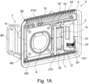
- FIGS. 1A to 4C show a first exemplary embodiment of an adjustment device V according to the invention.
- This adjustment device V has a support frame T intended for installation in a body component of a vehicle as the support structure.
- the supporting frame T can be fixed to a body part via a fastening part BF.
- the support frame T surrounds a closure opening BO, which can be closed by a closure flap K adjustably mounted on the support frame T.
- a connection area AB bordered by the support frame T is accessible via the closure opening BO when the closure flap K is open.
- a connection socket A is provided on this connection area AB as a connection element for connecting a line.
- the connection socket A serves, for example, to plug in a charging cable.
- the battery of an electric vehicle can thus be charged via the connection socket A, for example.
- the closure flap K can be adjusted externally by means of a drive 3, specifically in the installed state as intended, essentially laterally backwards (or forwards) in relation to a longitudinal axis of the vehicle.
- An adjustment movement of the closure flap K for opening and closing is carried out via a motor 31 of the Drive 3 controlled.
- the motor 31 drives a lever system 2 via a toothed gear mechanism, which transmits an adjustment movement to the closing flap K.
- the gear train is formed by a first gear element in the form of a drive worm 33' driven by the motor 31 and a second gear element in the form of a gear 201' meshing therewith.
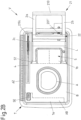
- the support frame T has a partition ST, which separates two spaces within the support frame T transversely to the direction in which the pivot axes S1 and S2 extend.
- the connection area AB with the connection socket A is arranged in a first space.
- the drive 3 is completely accommodated with the drive motor 31 and the gear train, and a receptacle L is formed.
- an adjustment bracket 21 of the adjustment device is completely accommodated.
- This adjustment bracket is formed by two pivoting levers 2a and 2b of the lever system 2, which are rigidly connected to one another by a connecting piece 210 at their protruding (upper) lever ends.
- the adjustment bracket 21, which is thus U-shaped, is held in a form-fitting manner on an inner side of the closure flap K via the connecting piece 210 and is connected to the closure flap K in an articulated manner.
- a bearing part 22 is formed between the two other (lower) ends of the pivoting levers 2a and 2b of the adjustment bracket 21 which are articulated on the support frame T.
- This bearing part 22, preferably made of plastic, is used to mount the gear wheel 201' as the second gear element of a gear train of the drive 3.
- This gear wheel 201' is non-rotatably connected to the bearing part 22 via bearing pins 20', which protrude on opposite end faces of the gear wheel 201' arranged. In this way, a rotation of the gearwheel 201' leads to the pivoting of the adjusting bracket 21 and its two pivoting levers 2a and 2b about the pivoting axis S1.
- a first gear element in the form of a drive worm 33' of the drive 3 is provided for rotating the gear 201'.
- This drive worm 33' meshes with the gear wheel 201' in order to open and close the shutter K.
- the lever system 2 has a single further one in addition to the adjustment bracket 21 with the two pivot levers 2a and 2b Pivoting lever 2c on. This cannot be driven directly by the drive motor 31, but is articulated about a second pivot axis S2 on the support frame T and on the closure flap K and is tracked only when the closure flap K is adjusted.
- the closure flap K is locked against tilting about the pivot axis S1 via the further individual pivoting lever 2c, which defines a further bearing point for the closure flap K.
- the single pivoted lever 2c is designed as an angle lever.
- the mounting of the individual pivoted lever 2c takes place on the support frame T behind a paneling part that faces the inside of the closed closure flap K.
- a through-opening in the form of a bearing slot 4 running longitudinally is provided in this covering part.
- the individual pivoted lever 2c is guided transversely to its pivot axis S2, in that its lever end 210c, which is articulated to the closing flap K, is inserted through the bearing slot 4.
- the bearing slot 4 runs in the intended installed state of the adjustment direction V essentially parallel to the longitudinal axis of the vehicle.
- a housing part 5 is provided within the support frame T and in particular within the space separated from the connection socket A by the partition ST. This housing part 5 is encompassed by the adjusting bracket 21 when it corresponds to the Figures 1A and 2A is pivoted, so the closure flap K is in a closed position.
- the closure flap K is in the adjustment V of Figures 1A to 4C connected to the lever system 2 in such a way that in a maximum open position of the closure flap K, this still at least partially covers the space with the housing part 5 and only makes a viewing area with the connection socket A accessible. In its open position according to the Figure 3B the closure flap K consequently covers in particular the adjusting bracket 21 and the bearing part 22 completely, as well as the individual pivoting lever 2c.
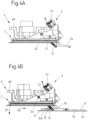
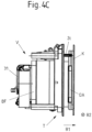
- a flat or circumferential sealing element DA is provided on the underside of the closing flap K. This sealing element DA is pressed against the connection socket A via the lever mechanism 2, when the shutter K is closed. This is in particular based on the Figures 4A to 4C illustrated in more detail.
- a control element can be provided on or inside the vehicle and/or on a remote control.
- a control element is provided (possibly additionally) directly in the area of the accessible connection socket A.
- this operating element is equipped with a sensor element SE, via which an operating event triggered by a user can be detected.
- the sensor element SE is part of a capacitive detection device in order to detect a movement performed by a finger or a hand of a user as a permissible operating event without contact.
- the actuating device V has two sensor devices 1a and 1b for opening the closing flap K by means of a gesture performed by a user.
- the sensor devices 1a and 1b each include at least one (sensor) electrode in order to capacitively detect a hand movement performed in front of the closed closure flap K, in particular a swiping movement, as an operating event for opening the closure flap K.
- the sensor devices 1a and 1b each have a printed circuit board for making electrical contact with a voltage supply and an electronic control unit for controlling the drive 3 . Electrodes of the control devices 1a and 1b can, for example, each be formed by means of a stamped grid and embedded in the (plastic) material of the support structure T.
- the two sensor devices 1a and 1b are arranged on opposite sides of the connection socket A, so that a wiping movement across the connection socket A can be reliably detected by means of the two sensor devices 1a and 1b.
- the one (second) sensor device 1b is arranged on the housing part 5, which protrudes in the receptacle L in the direction of the closing flap K.
- the installation space available on the side - here on the right - of the connection socket A can be used optimally, on the one hand to retract the adjustment bracket 21 in the closed position of the closure flap K and to stow it compactly and on the other hand to record a non-contact detection of an operating event in the area of the adjustment bracket 21.
- an operating event can be detected almost optimally without contact by changing capacitance values, in particular in the case of a closure flap K made of plastic.
- z. B. made of plastic or other electrically non-conductive material cap K with an electrically conductive element, z. B. in the form of a film to be provided as a capacitive coupling element.
- the measuring field for detecting the operating event can thus be shaped and/or enlarged.
- the electrically conductive element can be embedded in the closure flap, for example.
- the sensor devices 1a and 1b are covered with a panel section B for an aesthetically pleasing design of the area of the adjustment device V that can be seen when the closure flap K is open, in particular around the connection socket A.
- the panel section B covers the sensor devices 1a to the left of the connection socket A, the sensor device 1b and the top of the housing part 5 to the right of the connection socket A, as well as an edge surrounding the connection socket A, so that a uniform, flat surface is provided over this.
- the screen section B can be formed here by injection-moulded plastic material or a screen that is subsequently fastened.
- the sensor devices 1a and 1b which are spatially spaced apart from one another, can each be configured with one electrode or a plurality of, preferably two, electrodes and are provided for different functions.
- a gesture that is performed in front of the closed closure flap K can be detected as an operating event for opening the closure flap K via the sensor devices 1a and 1b.
- When closing the closure flap K is also on the sensor devices 1a and 1b or their electrodes and by means of in the Figure 3A Schematically illustrated electronic control unit 7, a possible obstacle in the adjustment path of the closing flap K can be detected.
- the opening of the closure flap K is measured in absolute terms by the sensor devices 1a and 1b in order to determine whether a capacitance value (increased compared to a basic capacitance) exceeds a threshold value and a hand of a user has thus approached the closure flap K and is performing a swiping movement when the closure flap K is closed, the measured values recorded by means of the sensor devices 1a and 1b are compared with empirical values serving as references. If the measured values deviate from the expected values stored in a memory of the electronic control unit 7 by more than a permissible amount, a possible obstacle in the adjustment path is indicated Closure flap K and in particular closed between an inside of the closure flap K and the vehicle body, which can be pinched by the closing flap K. In such a case, the adjustment movement of the closure flap K is automatically stopped or reversed.
- the electronic control unit 7 is coupled to the drive 3 for this purpose.
- the expected values used when the closing flap K is closed have been stored, for example, by way of a calibration when the open closing flap K is moved into its closed position (or open position) without any obstacles. An expected value is thus stored in each case for different adjustment positions of the closure flap K relative to the supporting structure T. If necessary, several obstacle-free adjustments can also be used in order to store several expected values in a position-resolved manner. If several unobstructed adjustment cycles are used, an expected value can be formed and stored, for example, by a mean value of recorded measured values.
- an adaptive adjustment of the stored expected values provision can be made for the expected values to be automatically adjusted after a stored number of adjustment cycles without obstacles, in order to take account of any signs of wear or changed environmental influences.
- the risk of false triggering of an anti-trapping device, which is (also) defined by the sensor devices 1a and 1b, can thus be reduced.
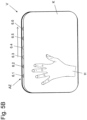
- FIG. 3A , 3B and 4B How based on Figures 3A , 3B and 4B is illustrated, it can also be provided in one embodiment to arrange (additional) electrodes 11, 12, 13 and 14 on the closure flap K itself, by means of which a gesture for opening and/or closing the closure flap K can be detected.
- the present four electrodes 11, 12 and 13, 14 arranged in pairs can be provided here instead of or in addition to the electrodes of the sensor devices 1a and 1b.
- the electrodes 11, 12, 13 and 14 are additionally provided, at least one gesture to open the closed closure flap K is detected with these.
- the (outer) electrodes 11, 12, 13 and 14 on the closure flap K serve as shielding electrodes to the outside for the (inner) electrodes of the sensor devices 1a and 1b, via which a possible obstacle in the adjustment path of the closing closure flap K should be detected.
- the electrodes 11, 12, 13 and 14 of the closure flap K are thus each operated differently depending on the direction of adjustment of the shutter K. There is a switchover from a detection function to a shielding function and vice versa, depending on whether the closure flap K is closed or should be closed.
- both pairs of electrodes 11, 12 and 13, 14 use stored threshold values to evaluate whether a user is swiping one hand from left to right to open the closure flap K across the closure flap K, which is then recorded as an operating event Triggering the opening of the shutter K is rated.
- the peripheral electrodes 11 and 14 are operated as shielding electrodes, while the inner electrodes 12 and 13 are used during the closing of the closure flap K to detect a possible case of pinching.
- All four electrodes 11, 12, 13 and 14 are therefore also part of an anti-trap device.
- only measured values recorded by the internal electrodes 12 and 13 are compared with stored expected values in order to conclude that there is a possible case of pinching in the event of an impermissibly large deviation from one or more expected values and to stop or reverse an adjustment of the closing flap K.
- the adjustment device V can not only be opened and, if necessary, closed under gesture control, but that a capacitive anti-trap device is also provided, which is at least partially provided via the same electrodes that are also used for gesture recognition.
- this sleep mode only one electrode is used to monitor whether an object is approaching the closed shutter K. If a measured value recorded using this electrode exceeds a stored threshold value, the electronic control unit 7 activated.
- the control unit 7 switches to an operating mode in which the occurrence of a gesture in the vicinity of the closed closure flap K is monitored with the at least one additional electrode, for example one of the sensor devices 1a, 1b or the electrodes 11 to 14, in order to open the release shutter K.
- a variant not shown in the figures also provides for the arrangement of electrodes on the closure flap K in such a way that at least one electrode is arranged closer to an inside and at least one electrode is arranged closer to an outside of the closure flap K.
- An (inner) electrode then serves as shielding when the closure flap K is closed and when it is opened, while the other (outer) electrode is used to detect an operating event and, if necessary, to detect an obstacle in the adjustment path of the opening closure flap K.
- the at least one (outer) electrode is used for shielding, while the other (inner) electrode takes on a measuring function and, as part of the anti-trapping device, monitors the occurrence of a potential obstacle in the adjustment path of the closing closing flap K .
- the individual electrodes can each measure against ground (or a reference potential).
- the electrodes can be arranged one above the other on or in the closure flap K in a sandwich construction.
- a 2-electrode principle can be implemented for opening (closing) and a one-electrode principle for closing (opening).
- a 2-electrode principle a changing capacitance is measured via a transmitter electrode and a receiver electrode, which usually decreases when an object approaches the closure flap K.
- a capacitance is measured against ground (or a reference potential), with a measured capacitance increasing when an object approaches.
- a display element AZ is provided (see in particular Figures 1A to 2B ), which is protected by a translucent cover AD when installed as intended.
- This display element AZ can, for example, be a light bar with one or more LEDs include. Further details for a possible operation of the display element AZ are in this case explained below Figures 5A to 5D shown.
- the pivot axis S1 and S2 of the lever mechanism 2 in the Figures 1A to 4C illustrated embodiment are provided eccentrically and in an area near the edge of the closure opening BO.
- the closure flap K can be adjusted in such a way that when it is opened, it is primarily lifted off the connection socket A along a first spatial direction R1 and, in a superimposed adjustment movement, essentially along a second direction perpendicular thereto running spatial direction R2 relative to the vehicle longitudinal axis is shifted to the rear.
- the closure flap K In an open position, the closure flap K is then at a comparatively small distance from an adjacent body outer skin and consequently takes up relatively little space in the open state.
- the closure flap K is consequently moved forward as far as possible during the adjustment between the closed position and the open position and is thus at a maximum distance along the spatial direction R1 running transversely to the pivot axis S1 or S2 from the connection socket A and the outer body skin surrounding the support frame T , but not in the fully open position.
- the inventively designed adjustment devices V with the lever mechanism 2 are comparatively compact and therefore take up little space on the body of the vehicle.
- a closure opening BO on the body can be easily closed in a sealing manner in that the closure flap K can be pulled into or against a sealing seat using the lever mechanism 2 with a sufficiently high force.
- the adjustment devices V shown are preferably designed as a prefabricated adjustment module in which the drive 3 and the lever system 2 are already functionally arranged on the support frame T to be inserted into a body opening. If necessary, the closure flap K can also already be mounted on a prefabricated, functional adjustment module with the support frame T, the drive 3 and the lever mechanism 2 . If a sensor system is provided for detecting an operating event on the adjustment device V and/or if a display element AZ is provided on the adjustment device V, the respective element is preferably also already fully functionally pre-assembled on the adjustment module in order to provide a pre-testable assembly that only needs to be to assemble the body part and with a power supply and possibly a higher-level control electronics is to be coupled.
- FIG. 5A to 5D A possible control of the display element AZ is illustrated in order to give a user a visual indication of how he has to move his hand H in front of the closed closure flap K via several light sources of the display element AZ, here in the form of individual LEDs 6.1 to 6.6 to detect an operating event for opening the shutter K without contact via a capacitive detection device (with the sensor element SE).
- the individual LEDs 6.1 to 6.6 are arranged here in a row one behind the other and on a (here upper) edge area of the closure opening BO, so that light emitted by the LEDs 6.1 to 6.6 is visible even when the closure flap K is closed.
- a swiping movement which a user executes with his hand H in front of the closed closure flap K from left to right, is evaluated as a permissible operating event for opening via the capacitive detection device.
- the gesture performed with the hand H is reminiscent of a pushing movement, but the hand H does not touch the closing flap K.
- the individual LEDs 6.1 to 6.6 light up one after the other. The visual impression of a "running light" is created on the edge of the closing flap K.
- closure flap open is displayed via the display element AZ, for example by all LEDs 6.1 to 6.6 lighting up together for a specific time (e.g. 3, 4 or 5 seconds), in particular in a predetermined light color , for example white.
- a visual signal representative of this is also generated beforehand via the LEDs 6.1 to 6.6, for example in which the individual LEDs 6.1 to 6.6 flash briefly and/or synchronously.
- the display element AZ is presently designed in such a way and controlled via display electronics that charging progress when a charging plug is plugged into the connection socket A is also displayed visually for a user.
- a growth of a color-changing bar is visualized during charging via the light bar of the display element AZ defined by the LEDs 6.1 to 6.6.
- the LEDs 6.1 to 6.6 For example, if the battery is empty, only one LED 6.1 at the end of the light bar lights up red. When the battery is charged via a connected charging plug, this LED 6.1 and an adjacent LED 6.2 light up red after a while, and then three adjacent LEDs 6.1, 6.2 and 6.3 light up red. If the vehicle battery continues to be charged, four LEDs 6.1 to 6.4 light up in series and then additional LEDs in orange. If the battery is almost or fully charged, almost and then all LEDs 6.1 to 6.6 light up green. After the charging process has been completed and a charging plug has been unplugged from the connection socket A, this is also acknowledged visually via the display element AZ.
- the display element AZ on the adjusting device V is used not only to inform the user about an operating state of the adjusting device V and the level of a battery in the vehicle, but also to give the user a visual indication of the hand movement to be carried out to adjust the closing flap to display K.
- Closing of the closure flap K is triggered by touching or pressing the additionally provided sensor element SE.
- the (inner) electrodes of the sensor devices 1a and 1b as part of a Anti-trapping device operated in order to detect a possible obstacle in the adjustment path of the closing flap K and to automatically stop or reverse the adjustment movement of the closure flap K before a trapping event occurs.
- the (outer) electrodes 11, 12, 13, 14 provided on the closure flap K are then operated for shielding purposes so that objects present on the outside of the closure flap K are not detected as possible obstacles.
Description
Die vorliegende Erfindung betrifft eine Verstellvorrichtung nach dem Oberbegriff des Anspruchs 1.The present invention relates to an adjusting device according to the preamble of claim 1.
Eine solche Verstellvorrichtung weist wenigstens eine Verschlussklappe zum zumindest teilweisen Verschließen einer Verschlussöffnung an einem Fahrzeug auf, über die bei geöffneter Verschlussklappe ein Anschlusselement für das Anschließen einer Leitung und/oder eine Befüllungsöffnung für das Nachfüllen einer Flüssigkeit, insbesondere eines Kraftstoffs zugänglich ist. Bei der Verschlussklappe handelt es sich somit beispielsweise um eine Tankklappe oder einen Tankdeckel an dem Fahrzeug, über die eine Befüllungsöffnung zum Nachfüllen von Wischwasser oder Öl zugänglich ist. Ebenso kann es sich bei der Verschlussklappe um eine Abdeckklappe oder einen Deckel handeln, über die oder den eine Anschlussbuchse für ein Ladekabel bei einem Elektrofahrzeug schützend abgedeckt ist. Üblicherweise wird über die Verschlussklappe eine Mulde oder ein Hohlraum an der Fahrzeugkarosserie abgedeckt, innerhalb derer z.B. ein eine Tanköffnung oder eine Anschlussbuchse vorliegt.Such an adjusting device has at least one closure flap for at least partially closing a closure opening on a vehicle, via which, when the closure flap is open, a connection element for connecting a line and/or a filling opening for refilling a liquid, in particular a fuel, is accessible. The closing flap is therefore, for example, a tank flap or a tank cap on the vehicle, via which a filling opening for topping up with wiper water or oil is accessible. The closure flap can also be a cover flap or a cover, which is used to protectively cover a connection socket for a charging cable in an electric vehicle. Usually, the closure flap covers a depression or cavity on the vehicle body, within which there is, for example, a tank opening or a connection socket.
Im Zuge der zunehmenden Automatisierung und zur Komfortsteigerung sind derartige Verschlussklappen an einem Fahrzeug heutzutage über einen regelmäßig elektromotorischen Antrieb fremdkraftbetätigt verstellbar. Eine solche Lösung zeigt beispielsweise die
Bisher aus der Praxis bekannte Verstellvorrichtungen mit derartigen Verschlussklappen weisen regelmäßig eine vergleichsweise aufwendige und/oder sperrige Verstellmechanik auf, die viel Bauraum innerhalb der Mulde / des Hohlraums oder benachbart hierzu beanspruchen und umständlich zu bedienen sind. Die Verstellvorrichtung der
Eine weitere Verstellvorrichtung zu Verstellen einer Verschlussklappe zum Verschließen einer Verschlussöffnung an einem Fahrzeug ist aus der
Es ist daher Aufgabe der vorliegenden Erfindung, eine Verschlussvorrichtung bereitzustellen, die in dieser Hinsicht verbessert ist und einfacher und/oder sicherer zu bedienen ist.It is therefore the object of the present invention to provide a closure device which is improved in this respect and is easier and/or safer to operate.
Diese Aufgabe wird mit einer Verstellvorrichtung des Anspruchs 1 gelöst.This object is achieved with an adjusting device of claim 1.
Erfindungsgemäß ist eine Verstellvorrichtung vorgeschlagen, die eine Verschlussklappe zum zumindest teilweisen Verschließen einer Verschlussöffnung an einem Fahrzeug umfasst. Über die Verschlussöffnung ist bei geöffneter Verschlussklappe ein Anschlusselement für das Anschließen einer Leitung und/oder eine Befüllungsöffnung für das Nachfüllen einer Flüssigkeit zugänglich. Die Verstellvorrichtung umfasst ferner einen Antrieb zum fremdkraftbetätigten Verstellen der Verschlussklappe auf ein Bedienereignis hin sowie eine mit dem Antrieb gekoppelte elektronische Steuereinheit. Mittels der Steuereinheit ist dabei der Antrieb einerseits auf ein berührungslos erfasstes Bedienereignis hin zum Öffnen der Verschlussklappe aktivierbar und andererseits automatisch stoppbar oder reversierbar, sofern beim Schließen der Verschlussklappe über eine Einklemmschutzeinrichtung berührungslos ein mögliches Hindernis im Verstellweg der sich schließenden Verschlussklappe detektiert wird, wobei mindestens eine Elektrode vorgesehen ist, die sowohl zur Detektion eines Bedienereignisses, um die Verschlussklappe zu öffnen, als auch als Teil der Einklemmschutzeinrichtung genutzt ist. Die mindestens eine Elektrode erfüllt somit eine Doppelfunktion und dient einerseits der Detektion eines Bedienereignisses und bildet andererseits einen Teil der Einklemmschutzeinrichtung.According to the invention, an adjusting device is proposed which includes a closure flap for at least partially closing a closure opening on a vehicle. When the closure flap is open, a connection element for connecting a line and/or a filling opening for refilling a liquid is accessible via the closure opening. The adjusting device also includes a drive for adjusting the closing flap in response to an operating event, and an electronic control unit coupled to the drive. The drive can be activated by means of the control unit on the one hand in response to an operator event recorded without contact in order to open the closure flap and on the other hand it can be automatically stopped or reversed if, when the closure flap is closed, a possible obstacle in the adjustment path of the closing closure flap is detected contactlessly via an anti-trap device, with at least one Electrode is provided, which is used both for detecting an operating event to open the shutter, as well as part of the anti-trap device. The at least one electrode thus fulfills a dual function and is used on the one hand to detect an operator control event and on the other hand forms part of the anti-trapping device.
Bei einer erfindungsgemäßen Verstellvorrichtung ist somit eine Sensorik zum berührungslosen Erkennen eines Bedienereignisses, das für das Öffnen der geschlossenen Verschlussklappe maßgeblich ist, mit einer Einklemmschutzeinrichtung kombiniert, die mögliche Hindernisse im Verstellweg der sich schließenden Verschlussklappe detektieren kann. Über die Einklemmschutzeinrichtung ist dabei verhindert, dass beispielsweise eine Hand eines Nutzers zwischen der sich schließenden Verschlussklappe und einem Teil der Fahrzeugkarosserie eingeklemmt wird. Die Hindernisdetektion erfolgt hierbei gleichfalls berührungslos, vorzugsweise kapazitiv oder induktiv.In an adjustment device according to the invention, a sensor system for contactless detection of an operating event that is decisive for opening the closed closure flap is combined with an anti-trapping device that can detect possible obstacles in the adjustment path of the closing closure flap. The anti-trap device prevents a user's hand, for example, from being pinched between the closing closure flap and a part of the vehicle body. In this case, the obstacle detection also takes place without contact, preferably capacitively or inductively.
Eine Befüllungsöffnung ist bevorzugt für die Verbrauchsstoffbefüllung an einem Fahrzeug ausgebildet und vorgesehen. Bei einem Verbrauchsstoff kann es sich beispielsweise um einen Energieträger für den Fahrzeugantrieb, wie zum Beispiel Kraftstoff, insbesondere Benzin, Diesel, Druckluft oder Wasserstoff, oder um eine Verbrauchsflüssigkeit, wie zum Beispiel Motoröl, Kühlflüssigkeit oder Wischwasser für eine Scheibenwischeranlage, handeln. Ein Anschlusselement ist demgegenüber vorzugsweise für das Anschließen einer Leitung ausgebildet und vorgesehen. Unter einem Anschlusselement wird folglich in diesem Zusammenhang insbesondere eine Anschlussmöglichkeit für ein Ladekabel verstanden, um eine Batterie des Fahrzeugs, insbesondere die Batterie eines Elektro- oder Hybridfahrzeugs aufzuladen.A filling opening is preferably designed and provided for filling consumables on a vehicle. A consumable can be, for example, an energy carrier for the vehicle drive, such as fuel, in particular gasoline, diesel, compressed air or hydrogen, or a consumable liquid, such as engine oil, coolant or washer fluid for a windshield wiper system. In contrast, a connection element is preferably designed and provided for the connection of a line. In this context, a connection element is understood to mean in particular a connection option for a charging cable in order to charge a battery of the vehicle, in particular the battery of an electric or hybrid vehicle.
Hierbei kann nach einer Variante vorgesehen sein, dass die elektronische Steuereinheit eingerichtet ist,
- (a) für das Öffnen der Verschlussklappe auszuwerten, ob ein mittels der mindestens einen Elektrode erfasster Messwert einen Schwellwert überschreitet, und
- (b) beim Schließen der Verschlussklappe wenigstens einen mittels der mindestens einen Elektrode erfassten Messwert mit einem Erwartungswert zu vergleichen.
- (a) to evaluate for the opening of the closure flap whether a measured value recorded by means of the at least one electrode exceeds a threshold value, and
- (b) to compare at least one measured value recorded by means of the at least one electrode with an expected value when the closing flap is closed.
Bei geschlossener Verschlussklappe wird somit die mindestens eine Elektrode z.B. zunächst lediglich dazu genutzt, zu prüfen, ob ein bestimmter Schwellwert für eine gemessene Kapazität einen hinterlegten Schwellwert überschreitet, um auf ein mögliches Bedienereignis an der Verschlussklappe zu schließen. So erfolgt beispielsweise durch die Annäherung einer Hand an die geschlossene Verschlussklappe eine messbare Kapazitätsänderung in der Umgebung der Verschlussklappe. Übersteigt die gemessene Kapazität einen hinterlegten Schwellwert, wird dies als Bedienereignis gewertet oder zumindest als ein erster Indikator für ein mögliches Bedienereignis, wenn beispielsweise erst mit einer bestimmten Geste das Öffnen der Verschlussklappe auslösbar sein soll. Bei geschlossener Verschlussklappe wird folglich mittels der mindestens einen Elektrode absolut gemessen, um ein mögliches Bedienereignis zu detektieren.When the closure flap is closed, the at least one electrode is thus initially only used, for example, to check whether a specific threshold value for a measured capacitance exceeds a stored threshold value in order to conclude that a possible operating event on the closure flap has occurred. For example, when a hand approaches the closed closure flap, there is a measurable change in capacitance in the vicinity of the closure flap. If the measured capacity exceeds a stored threshold value, this is evaluated as an operating event or at least as a first indicator of a possible operating event, if, for example, the opening of the closing flap should only be able to be triggered with a specific gesture. At closed closure flap is consequently measured in absolute terms by means of the at least one electrode in order to detect a possible operating event.
Ein für die Detektion eines Bedienereignisses hinterlegter Schwellwert kann grundsätzlich anpassbar sein, insbesondere über eine Betriebszeit der Verstellvorrichtung, beispielsweise in Abhängigkeit von sich ändernden äußeren Umgebungsbedingungen. Insbesondere kann der Schwellwert in Abhängigkeit von einer (Außen-) Temperatur oder Feuchtigkeit im Bereich der Verschlussklappe anpassbar sein. Hierfür ist die elektronische Steuereinheit in einer Ausführungsvariante mit wenigstens einem Sensor gekoppelt, der mindestens einen Messwert, z.B. für die Temperatur oder Feuchtigkeit liefert, und die Steuereinheit ist eingerichtet, den Schwellwert in Abhängigkeit von diesem mindestens einen Messwert anzupassen, also zu erhöhen oder zu erniedrigen oder mit einem neuen, d.h., neu berechneten Schwellwert zu ersetzen.A threshold value stored for the detection of an operator control event can in principle be adaptable, in particular over an operating time of the adjustment device, for example as a function of changing external environmental conditions. In particular, the threshold value can be adjustable as a function of an (outside) temperature or humidity in the area of the closure flap. For this purpose, in one embodiment variant, the electronic control unit is coupled to at least one sensor that supplies at least one measured value, e.g. for the temperature or humidity, and the control unit is set up to adapt the threshold value as a function of this at least one measured value, i.e. to increase or decrease it or to replace it with a new, i.e. newly calculated threshold value.
Eine Anpassung eines Schwellwertes auf Basis geänderter Umgebungsbedingungen schließt ferner eine Ausführungsvariante ein, bei der bei bestimmungsgemäß geschlossener Verschlussklappe ein Basis-Messwert, z.B. eine Grundkapazität, erfasst wird und in Abhängigkeit von diesem eine Anpassung des Schwellwertes erfolgt. Wird z.B. bei geschlossener Verschlussklappe eine Veränderung dieses Basis-Messwertes über eine als zulässig definierte Toleranz hinaus detektiert, wird der Basis-Messwert aktualisiert und in entsprechendem Maße auch der Schwellwert angepasst. In einer Variante wird mittels der elektronischen Steuereinheit bei Aktivierung der Verstellvorrichtung, insbesondere bei einem Aufwachen aus einem Ruhemodus oder Schlafmodus ("sleep mode") ein Schwellwert automatisch in Abhängigkeit von einer gemessenen Grundkapazität angepasst.An adaptation of a threshold value on the basis of changed environmental conditions also includes an embodiment variant in which a basic measured value, e.g. a basic capacitance, is recorded when the closure flap is closed as intended and the threshold value is adapted as a function of this. If, for example, a change in this basic measured value beyond a tolerance defined as permissible is detected when the shutter is closed, the basic measured value is updated and the threshold value is also adjusted accordingly. In one variant, a threshold value is automatically adjusted as a function of a measured basic capacitance by means of the electronic control unit when the adjusting device is activated, in particular when waking up from a sleep mode.
Bei geöffneter Verschlussklappe wird ein von der mindestens einen Elektrode erfasster Messwert mit wenigstens einem hinterlegten Erwartung- oder Referenzwert verglichen, um bei einer eventuellen Abweichung des Messwerts - über eine zulässige Toleranz hinaus - auf ein mögliches Hindernis im Verstellweg der sich schließenden Verschlussklappe zu folgern. Der Erwartungswert stellt dabei einen Soll-Messwert für eine störungsfreie, d.h., hindernisfreie Verstellbewegung der geöffneten Verschlussklappe in eine Verschlussposition dar.When the closure flap is open, a measured value recorded by the at least one electrode is compared with at least one stored expected or reference value in order to infer a possible obstacle in the adjustment path of the closing closure flap if there is a deviation in the measured value—beyond a permissible tolerance. The expected value represents a target measured value for a trouble-free, i.e. obstacle-free adjustment movement of the open closure flap into a closed position.
In diesem Zusammenhang kann auch vorgesehen sein, dass ein Speicher vorgesehen ist, in dem für unterschiedliche Positionen der Verschlussklappe entlang eines Verstellwegs der Verschlussklappe jeweils ein Erwartungswert gespeichert ist, und die elektronische Steuereinheit eingerichtet ist, beim Schließen der Verschlussklappe einen positionsaufgelösten Vergleich mittels der mindestens einen Elektrode erfasster Messwerte mit den gespeicherten Erwartungswerten durchzuführen. Es wird somit an den unterschiedlichen Positionen jeweils geprüft, inwieweit ein Messwert mit einem hinterlegten Erwartungswert übereinstimmt. Wird eine unzulässige Abweichung festgestellt, wird auf ein Hindernis im Verstellweg der sich schließenden Verschlussklappe geschlossen.In this context, it can also be provided that a memory is provided in which an expected value is stored for different positions of the closure flap along an adjustment path of the closure flap, and the electronic control unit is set up to carry out a position-resolved comparison of measured values recorded by means of the at least one electrode with the stored expected values when the closing flap is closed. It is thus checked at the different positions to what extent a measured value corresponds to a stored expected value. If an impermissible deviation is determined, an obstacle in the adjustment path of the closing flap is assumed.
In einer Weiterbildung ist eine Auswertelogik der elektronischen Steuereinheit ferner dazu eingerichtet, im Rahmen einer Diagnosefunktion anhand von einzelnen Erwartungswerten abweichenden Messwerten auf eine etwaige Fehlfunktion der Verschlussvorrichtung zu schließen. Die elektronische Steuereinheit ist in dieser Variante somit dazu eingerichtet und vorgesehen, auf Basis von beim Schließen der Verschlussklappe erfasster Messwerte und deren Vergleich mit hinterlegten Erwartungswerten sowohl auszuwerten, ob ein Hindernis im Verstellweg der sich schließenden Verschlussklappe vorliegt, als auch auszuwerten, ob die Verstellung der Verschlussklappe, beispielsweise aufgrund von Verschleiß, nicht mehr ordnungsgemäß abläuft. Die Diagnosefunktion kann auch beim Öffnen der Verschlusskappe durchgeführt werden.In one development, an evaluation logic of the electronic control unit is also set up to infer a possible malfunction of the closure device within the scope of a diagnostic function based on measured values that deviate from individual expected values. In this variant, the electronic control unit is therefore set up and intended to evaluate, on the basis of measured values recorded when the closing flap is closed and their comparison with stored expected values, whether there is an obstacle in the adjustment path of the closing closing flap, and also to evaluate whether the adjustment of the Closing flap, for example due to wear and tear, no longer runs properly. The diagnostic function can also be carried out when opening the sealing cap.
Die im Speicher der Verstellvorrichtung hinterlegten Erwartungswerte sind beispielsweise über eine Kalibrierung bei einer hindernisfreien Verstellung oder mehrerer hindernisfreien Verstellungen der Verschlussklappe ausgehend von ihrer geöffneten Stellung in ihre Verschlussposition und/oder bei einer Verstellung ausgehend von ihrer Verschlussposition in die geöffnete Stellung abgespeichert worden. In diesem Zusammenhang kann auch vorgesehen sein, dass im Betrieb der Verstellvorrichtung eine adaptive Anpassung der hinterlegten Erwartungswerte über wenigstens eine spätere hindernisfreie Verstellung erfolgt. Beispielsweise können hierfür bei jeder hindernisfreien Verstellung der Verschlussklappe in ihre Verschlussposition oder in die geöffnete Stellung die hinterlegten Erwartungswerte überschrieben werden, um hierdurch eine Anpassung an etwaige Verschleißerscheinungen oder geänderte Umgebungsbedingungen vorzunehmen. Alternativ kann vorgesehen sein, eine entsprechende Anpassung eines hinterlegten Erwartungswertes jeweils nur nach einer bestimmten Anzahl von störungsfrei abgelaufenen Verstellzyklen vorzunehmen. Eine Anpassung der hinterlegten Erwartungswerte erfolgt somit beispielsweise nur alle 5, 10 oder mehr Verstellzyklen.The expected values stored in the memory of the adjustment device have been stored, for example, via a calibration during an unobstructed adjustment or several unobstructed adjustments of the closure flap starting from its open position to its closed position and/or during an adjustment starting from its closed position to the open position. In this context, provision can also be made for the stored expected values to be adapted adaptively during operation of the adjustment device via at least one subsequent adjustment free of obstacles. For example, the stored expected values can be overwritten for each obstacle-free adjustment of the closure flap to its closed position or to the open position, in order to adapt to any signs of wear or changed environmental conditions. Alternatively, provision can be made for a corresponding adjustment of a stored expected value to be carried out only after a specific number of adjustment cycles that have run without problems. The stored expected values are therefore only adjusted every 5, 10 or more adjustment cycles, for example.
Eine Anpassung wenigstens eines im Speicher hinterlegten Erwartungswertes kann selbstverständlich nicht nur durch einfaches Überschreiben mit einem neu erfassten Erwartungswert erfolgen. Eine (adaptive) Anpassung eines hinterlegten Erwartungswertes schließt vielmehr auch eine situative Einrechnung eines bestimmten, variablen Offset-Wertes zu einem im Speicher hinterlegten Erwartungswert ein. Ein solcher Offset-Wert trägt beispielsweise geänderten Temperaturen oder erhöhter Feuchtigkeit im Bereich der Verschlussklappe Rechnung, wodurch sich insbesondere messbare Kapazitätswerte ändern können.Of course, at least one expected value stored in the memory cannot only be adjusted by simply overwriting it with a newly recorded expected value. An (adaptive) adjustment of a stored expected value rather also includes a situational inclusion of a specific, variable offset value to an expected value stored in the memory. Such an offset value takes into account, for example, changed temperatures or increased humidity in the area of the closure flap, as a result of which measurable capacitance values in particular can change.
Die mindestens eine Elektrode kann bei geschlossener Verschlussklappe auch dazu genutzt werden, ein Aufwachen der elektronischen Steuereinheit auf ein Aufwachereignis hin auszulösen. So kann zur Energieeinsparung vorgesehen sein, dass die elektronische Steuereinheit in einem Schlafmodus ("sleep mode") betreibbar ist, in dem beispielsweise lediglich eine von mehreren Elektroden angesteuert ist. Wird an dieser einen Elektrode eine erhöhte Kapazität festgestellt, beispielsweise indem sich die Hand eines Nutzers der geschlossenen Verschlussklappe annähert, wacht die elektronische Steuereinheit auf und wechselt in einen Betriebsmodus, in dem durch die elektronische Steuereinheit auch die weiteren Elektroden angesteuert und deren Messwerte ausgewertet werden, um die Umgebung der Verschlussklappe auf das Auftreten eines möglichen Bedienereignisses hin zu überwachen.When the closure flap is closed, the at least one electrode can also be used to trigger the electronic control unit to wake up in response to a wake-up event. In order to save energy, provision can be made for the electronic control unit to be operable in a sleep mode, in which, for example, only one of a plurality of electrodes is activated. If an increased capacity is detected at this one electrode, for example when a user's hand approaches the closed flap, the electronic control unit wakes up and switches to an operating mode in which the electronic control unit also controls the other electrodes and evaluates their measured values. to monitor the vicinity of the shutter for the occurrence of a possible operator event.
Wird mindestens eine Elektrode der Verstellvorrichtung sowohl für die Detektion eines Aufwachereignisses, um die elektronische Steuereinheit von einem Schlafmodus in einen aktiven Betriebsmodus wechseln zu lassen, als auch für die Detektion eines Bedienereignisses genutzt, kann vorgesehen sein, dass in der elektronischen Steuereinheit für diese eine Elektrode wenigstens zwei Schwellwerte hinterlegt sind. Überschreitet im Schlafmodus der Steuereinheit eine mittels der Elektrode gemessene Kapazität in der Umgebung der Verschlussklappe einen (niedrigeren) Schwellwert, wird dies als Aufwachereignis bewertet. Wird im Anschluss daran, bei aufgewachter elektronische Steuereinheit, über diese Elektrode im Anschluss eine Kapazität gemessen, die auch den (höheren, ersten) Schwellwert überschreitet, wird dies als Bedienereignis oder zumindest als Teil des Bedienereignisses bewertet. Bei einer Bewertung als Teil eines Bedienereignisses muss beispielsweise an wenigstens einer weiteren Elektrode der Verschlussvorrichtung ein (zweiter) Schwellwert für eine gemessene Kapazität überschritten werden und dies mithin in bestimmter zeitlicher Abfolge zu der Überschreitung eines Kapazitätswertes, der für die erste Elektrode gemessen wird. Treten die an unterschiedlichen Elektroden gemessenen Kapazitätsänderungen in einer charakteristischen Größe und Abfolge auf, kann auf das Ausführen einer bestimmten Geste im Umfeld der geschlossenen Verschlussklappe, zum Beispiel auf eine mit einer Hand eines Nutzers ausgeführte Wischbewegung, geschlossen werden, die dann als Auslöser für das Öffnen der Verschlussklappe bedient.If at least one electrode of the adjustment device is used both for the detection of a wake-up event, in order to have the electronic control unit switch from a sleep mode to an active operating mode, and for the detection of an operating event, it can be provided that in the electronic control unit for this one electrode at least two threshold values are stored. If, in the sleep mode of the control unit, a capacitance measured by means of the electrode in the vicinity of the closure flap exceeds a (lower) threshold value, this is evaluated as a wake-up event. If thereafter, with the electronic control unit awake, a capacitance is measured via this electrode which also exceeds the (higher, first) threshold value, this is evaluated as an operating event or at least as part of the operating event. In the case of an evaluation as part of an operating event, a (second) threshold value for a measured capacitance must be exceeded on at least one other electrode of the closure device, for example, and this must therefore be done in a specific time sequence to the exceeding of a capacitance value that is measured for the first electrode. If the changes in capacitance measured at different electrodes occur in a characteristic size and sequence, a certain gesture can be made in the vicinity of the closed flap, for example one with a A user's hand executed wiping motion, are closed, which then used as a trigger for opening the shutter.
Zur Vermeidung von etwaigen Fehlauslösungen ist die elektronische Steuereinheit in einer Variante eingerichtet, ein Öffnen der Verschlussklappe erst auszulösen und/oder erst "aufzuwachen", wenn der (jeweilige) Schwellwert von dem mindestens einen erfassten Messwert wenigstens für eine vorgegebene Zeitdauer überschritten wird. Dies schließt insbesondere ein, dass festgestellt wird, ob eine bestimmte Anzahl mehrerer, vorzugsweise (unmittelbar) aufeinanderfolgender Messwerte jeweils den Schwellwert überschreitet und hierdurch auf eine Überschreitung des (jeweiligen) Schwellwerts für eine vorgegebene Zeitdauer geschlossen wird.In order to avoid any false triggering, the electronic control unit is set up in one variant to only trigger an opening of the closure flap and/or only "wake up" when the (respective) threshold value of the at least one recorded measured value is exceeded at least for a predetermined period of time. This includes in particular that it is determined whether a specific number of multiple, preferably (immediately) consecutive measured values exceeds the threshold value in each case and it is thereby concluded that the (respective) threshold value has been exceeded for a predetermined period of time.
Wie bereits zuvor angesprochen, ist es insbesondere für eine berührungslose Erkennung einer im Umfeld der geschlossenen Verschlussklappe ausgeführte Geste als Bedienereignis vorteilhaft, mindestens zwei mit der elektronischen Steuereinheit gekoppelte Elektroden vorzusehen.As already mentioned above, it is particularly advantageous for contactless recognition of a gesture performed in the vicinity of the closed closure flap as an operating event to provide at least two electrodes coupled to the electronic control unit.
In einer möglichen Ausführungsvariante sind dann die mindestens zwei Elektroden und die elektronische Steuereinheit eingerichtet,
- (a) für das Öffnen der Verschlussklappe eine bestimmte in der Umgebung der geschlossenen Verschlussklappe ausgeführte Geste eines Nutzers als Bedienereignis zu detektieren und
- (b) beim Schließen der Verschlussklappe Messwerte zu erfassen und mit in der elektronischen Steuereinheit hinterlegten Erwartungswerten zu vergleichen, um berührungslos auf ein mögliches Hindernis im Verstellweg der Verschlussklappe zu schließen.
- (a) to detect a specific gesture performed by a user in the vicinity of the closed closure flap as an operating event for opening the closure flap and
- (b) to record measured values when the closing flap is closed and to compare them with expected values stored in the electronic control unit in order to detect a possible obstacle in the adjustment path of the closing flap without contact.
Die elektronische Steuereinheit kann hierbei eingerichtet sein, für das Öffnen der Verschlussklappe auszuwerten, ob mittels unterschiedlicher Elektroden erfasste Messwerte in einer vorgegebenen Abfolge erste und zweite Schwellwerte überschreiten. Derart kann beispielsweise eine Wischbewegung berührungslos erfasst werden, bei der durch die Hand eines Nutzers zuerst an der einen und anschließend an der anderen hierzu (räumlich) beabstandeten Elektrode ein erhöhter Kapazitätswert messbar ist.In this case, the electronic control unit can be set up to evaluate for the opening of the closure flap whether measured values recorded by means of different electrodes exceed first and second threshold values in a predetermined sequence. In this way, for example, a swiping movement can be detected without contact, in which an increased capacitance value can be measured by the hand of a user first on one electrode and then on the other (spatially) spaced apart electrode.
In einer Ausführungsvariante ist mindestens eine Elektrode
- (a) für das Öffnen der Verschlussklappe zur Erfassung eines Messwerts genutzt, um ein Bedienereignis zu detektieren, und
- (b) beim Schließen der Verschlussklappe zur elektromagnetischen Abschirmung genutzt. Mittels der elektronischen Steuereinheit ist hierbei die jeweilige Elektrode entsprechend angesteuert, sodass diese in zwei Betriebsarten unterschiedlich nutzbar ist, einerseits zur Erfassung eines Messwertes für die Detektion eines das Öffnen der geschlossenen Verschlussklappe auslösenden Bedienereignisses und andererseits als Schirmelektrode, über die ein elektrisches Feld einer anderen Elektrode beeinflusst wird, die beim Schließen der Verschlussklappe zur Detektion eines möglichen Hindernisses im Verstellweg der sich schließenden Verschlussklappe genutzt wird. Die mindestens eine Elektrode ist hierbei folglich einerseits für das Öffnen der Verschlussklappe zur Detektion eines Bedienereignisses genutzt und andererseits als Schirmelektrode um eine Detektion eines möglichen Hindernisses im Verstellweg der sich schließenden Verschlussklappe mittels wenigstens einer weiteren Elektrode zu verbessern. Die eine für das Öffnen der Verschlussklappe genutzte Elektrode ist somit auch Teil der Einklemmschutzeinrichtung, hier jedoch nicht selbst zur Detektion eines Hindernisses genutzt, sondern als Schirmelektrode.
- (a) used for opening the shutter to acquire a measurement to detect an operator event, and
- (b) used for electromagnetic shielding when closing the shutter. The respective electrode is controlled accordingly by means of the electronic control unit, so that it can be used differently in two operating modes, on the one hand to record a measured value for the detection of an operating event that triggers the opening of the closed shutter and on the other hand as a shielding electrode, via which an electric field of another electrode is influenced, which is used when the closure flap is closed to detect a possible obstacle in the adjustment path of the closing closure flap. The at least one electrode is therefore used on the one hand for opening the closure flap to detect an operating event and on the other hand as a shielding electrode to improve detection of a possible obstacle in the adjustment path of the closing closure flap using at least one additional electrode. The one electrode used to open the closing flap is therefore also part of the anti-trapping device, but here it is not itself used to detect an obstacle, but rather as a shielding electrode.
Vor diesem Hintergrund ist in einer Weiterbildung mindestens eine weitere Elektrode als Teil der Einklemmschutzeinrichtung vorgesehen, mittels der ein Messwert zur Detektion eines möglichen Hindernisses im Verstellweg der zu schließenden Verschlussklappe erfasst wird, wobei die für das Öffnen der Verschlussklappe zur Detektion eines Bedienereignisses genutzte Elektrode beim Schließen der Verschlussklappe als Schirmelektrode für diese mindestens eine weitere Elektrode genutzt ist.Against this background, in a further development, at least one further electrode is provided as part of the anti-trap device, by means of which a measured value for detecting a possible obstacle in the adjustment path of the closure flap to be closed is recorded, with the electrode used for opening the closure flap for detecting an operating event when closing the closure flap is used as a shielding electrode for this at least one further electrode.
Auch in dieser Variante kann für das Öffnen der Verschlussklappe eine Geste als Bedienereignis bewertet werden. Hierfür sind dann mindestens drei Elektroden vorgesehen. Diese Elektroden und die elektronische Steuereinheit sind dann eingerichtet,
- (a) für das Öffnen der Verschlussklappe mittels eines Teils der Elektroden eine bestimmte in der Umgebung der geschlossenen Verschlussklappe ausgeführte Geste eines Nutzers als Bedienereignis zu detektieren und
- (b) beim Schließen der Verschlussklappe mittels eines anderen Teils der Elektroden Messwerte zu erfassen und mit in der elektronischen Steuereinheit hinterlegten Erwartungswerten zu vergleichen, um berührungslos auf ein mögliches Hindernis im Verstellweg der Verschlussklappe zu schließen.
- (a) to detect a specific gesture performed by a user in the vicinity of the closed closure flap as an operating event for opening the closure flap using part of the electrodes, and
- (b) when the closing flap is closed, using another part of the electrodes to record measured values and to compare them with expected values stored in the electronic control unit in order to detect a possible obstacle in the adjustment path of the closing flap without contact.
So können wenigstens zwei der Elektroden für die Detektion der Geste und zwei der Elektroden für die Detektion eines möglichen Hindernisses vorgesehen sein, wobei wenigstens eine Elektrode, die bei geschlossener Verschlussklappe für die Detektion einer Geste zum Öffnen der Verschlussklappe genutzt ist, beim Schließen der Verschlussklappe als Schirmelektrode genutzt ist, mithin als Schirmelektrode betrieben wird.At least two of the electrodes can be provided for detecting the gesture and two of the electrodes for detecting a possible obstacle, with at least one electrode being used for detecting a Gesture is used to open the flap, is used as a shielding electrode when closing the flap, and is therefore operated as a shielding electrode.
Hierbei werden beispielsweise eine erste und eine zweite Elektrode zur Gestenerkennung genutzt. Beim Schließen der Verschlussklappe werden die erste Elektrode und eine dritte Elektrode für eine kapazitive Detektion eines möglichen Hindernisses im Verstellweg der sich schließenden Verschlussklappe genutzt. Die zweite Elektrode fungiert dann während des Schließens der Verschlussklappe als Schirmelektrode.Here, for example, a first and a second electrode are used for gesture recognition. When the closing flap is closed, the first electrode and a third electrode are used for capacitive detection of a possible obstacle in the adjustment path of the closing closing flap. The second electrode then functions as a shielding electrode while the closure flap is being closed.
Die wenigstens eine beim Schließen der Verschlussklappe als Schirmelektrode genutzte Elektrode sollte hierbei auf Masse liegen.The at least one electrode used as a shielding electrode when the closing flap is closed should be grounded.
In einer Weiterbildung sind beispielsweise vier Elektroden vorgesehen. Hierbei dienen dann zwei Elektroden zur Erkennung eines Bedienereignisses bei geschlossener Verschlussklappe und zwei andere Elektroden werden zur Detektion eines möglichen Hindernisses und damit zur Sensierung eines möglichen Einklemmfalles beim Schließen der Verschlussklappe genutzt. Wird die Verschlussklappe geöffnet, so werden nur die zur Detektion eines Bedienereignisses genutzten Elektroden abgefragt. Wird die Verschlussklappe dann geschlossen, werden die beiden anderen Elektroden abgefragt. Während des Schließens der Verschlussklappe ändert sich eine über die Elektroden messbare Kapazität gegenüber der Fahrzeugkarosserie.In one development, four electrodes are provided, for example. In this case, two electrodes are then used to detect an operating event when the closure flap is closed, and two other electrodes are used to detect a possible obstacle and thus to sense a possible case of pinching when the closure flap is closed. If the closure flap is opened, only the electrodes used to detect an operating event are queried. If the flap is then closed, the other two electrodes are queried. While the closing flap is being closed, a capacitance that can be measured via the electrodes changes with respect to the vehicle body.
Eine entsprechende Änderung einer messbaren Kapazität ohne ein Hindernis stellt hierbei einen Erwartungswert dar, der bei hindernisfreier Verstellung eingehalten wird. Zur Verbesserung der Messung beim Schließen der Verschlussklappe werden die zwei Elektroden, die für die Erkennung des Bedienereignisses bei geschlossener Verschlussklappe genutzt wurden, als Schirmelektroden genutzt. Es erfolgt somit eine Umschaltung zwischen einer Detektionsfunktion und einer Schirmfunktion bei diesen Elektroden in Abhängigkeit von der Verstellposition (geschlossen/offen) oder der Verstellrichtung (in Richtung der geöffneten/in Richtung der Verschlussposition) der Verschlussklappe.A corresponding change in a measurable capacitance without an obstacle represents an expected value that is maintained in the case of an obstacle-free adjustment. To improve the measurement when the shutter is closed, the two electrodes used to detect the operator event when the shutter is closed are used as shielding electrodes. There is thus a switchover between a detection function and a shielding function with these electrodes depending on the adjustment position (closed/open) or the adjustment direction (towards the open/towards the closed position) of the closure flap.
Über eine entsprechende Schirmung mittels wenigstens einer Elektrode lässt sich hierbei beispielsweise in besonders einfacher Weise erreichen, dass etwaige an einer Außenseite der Verschlussklappe vorhandene Objekte nicht fälschlicherweise als mögliche Hindernisse detektiert werden, die beim Schließen der Verschlussklappe zwischen der Verschlussklappe und einer Fahrzeugkarosserie an der Innenseite der Verschlussklappe eingeklemmt würden.A corresponding shielding by means of at least one electrode can be achieved here, for example, in a particularly simple manner that any objects present on an outside of the closure flap are not incorrectly detected as possible obstacles that can occur when the closure flap is closed between the Closing flap and a vehicle body would be pinched on the inside of the closing flap.
In einer bevorzugten Ausführungsvariante ist die Verschlussklappe aus einem Kunststoffmaterial hergestellt. Dies erleichtert die kapazitive Sensierung.In a preferred embodiment, the closure flap is made of a plastic material. This facilitates capacitive sensing.
Eine Elektrode kann grundsätzlich zum Beispiel durch Stanzgitter, einen Kupferstreifen oder eine Kupferfolie gebildet sein. Die mindestens eine Elektrode kann ferner in das Material einer Tragstruktur der Verstellvorrichtung, z.B. in das Material eines Gehäuseteils, eingebettet sein. Hierbei kann die Elektrode durch zur Herstellung des Gehäuseteils genutztes (Kunststoff-) Material umspritzt sein. Alternativ kann die mindestens eine Elektrode nachträglich an der Tragstruktur oder dem bereits fertiggestellten Gehäuseteil befestigt sein, zum Beispiel hieran geklebt sein.In principle, an electrode can be formed, for example, by stamped grids, a copper strip or a copper foil. The at least one electrode can also be embedded in the material of a support structure of the adjustment device, e.g. in the material of a housing part. In this case, the electrode can be overmoulded with (plastic) material used to produce the housing part. Alternatively, the at least one electrode can be subsequently attached to the support structure or the already completed housing part, for example glued to it.
Eine Anbindung eines Stanzgitters an eine Spannungsversorgung und/oder eine Busleitung einer elektronischen Steuereinheit kann beispielsweise über Press-Fit-Pins des Stanzgitters erfolgen. Analog kann eine Anbindung von Motorkontakten des Antriebs ebenfalls über sogenannte Press-Fit-Pins oder Platinendirektstecker erfolgen. Insbesondere hierfür kann die Sensoreinrichtung eine Leiterplatte umfassen, über die die Motorkontakte des Antriebs angebunden sind. Bei Verwendung einer Leiterplatte und insbesondere von nicht über ein Stanzgitter ausgebildeter Elektroden kann eine elektrische Kontaktierung einer Elektrode an die Leiterplatte auch über einen Steckverbinder oder einen Druckkontakt erfolgen.A stamped grid can be connected to a voltage supply and/or a bus line of an electronic control unit, for example via press-fit pins of the stamped grid. Similarly, the motor contacts of the drive can also be connected via so-called press-fit pins or direct board connectors. For this purpose in particular, the sensor device can comprise a printed circuit board, via which the motor contacts of the drive are connected. When using a printed circuit board and, in particular, electrodes that are not formed via a stamped grid, an electrode can also be electrically contacted on the printed circuit board via a plug connector or a pressure contact.
Eine Leiterplatte der Sensoreinrichtung ist vorzugsweise an einer Tragstruktur der Verstellvorrichtung angeordnet. Bei der Ausbildung der Elektrode als Teil einer kapazitiven oder induktiven Erfassungseinrichtung zur Detektion eines Bedienereignisses wird in einer Ausführungsvariante über eine Rückseite der Leiterplatte eine Sensorfläche ausgebildet, mittels der ein Bedienereignis zum Verstellen der Verschlussklappe berührungslos detektierbar ist.A circuit board of the sensor device is preferably arranged on a support structure of the adjustment device. When the electrode is designed as part of a capacitive or inductive detection device for detecting an operating event, in one embodiment variant a sensor surface is formed on a rear side of the printed circuit board, by means of which an operating event for adjusting the closing flap can be detected without contact.
Um eine Elektrode im bestimmungsgemäß eingebauten Zustand der Verstellvorrichtung zu verkleiden, kann ein Blendenabschnitt vorgesehen sein, der die mindestens eine Elektrode überdeckt. Der Blendenabschnitt kann hierbei durch angespritztes Kunststoffmaterial gebildet sein oder durch eine nachträglich angebrachte Blende.In order to cover an electrode when the adjustment device is installed as intended, a screen section can be provided which covers the at least one electrode. The panel section can be formed by injection-moulded plastic material or by a panel that is attached later.
In einer Variante erstreckt sich der Blendenabschnitt wenigstens teilweise auch über den das Anschlusselement und/oder die Befüllungsöffnung aufweisenden Bereich der Verstellvorrichtung. Auf diese Weise kann vergleichsweise einfach eine einheitliche dem Benutzer bei geöffneter Verschlussklappe zugewandte Oberfläche erzielt werden. Bei mehreren Elektroden können diese ebenfalls durch denselben Blendenabschnitt schützend überdeckt sein.In one variant, the screen section also extends at least partially over the area of the adjusting device that has the connection element and/or the filling opening. In this way, a uniform surface facing the user when the closure flap is open can be achieved comparatively easily. If there are several electrodes, they can also be protectively covered by the same diaphragm section.
Wenigstens eine mit der elektronischen Steuereinheit gekoppelte Elektrode, mittels derer ein Bedienereignis zum Öffnen der Verschlussklappe detektierbar ist und/oder die als Teil der Einklemmschutzeinrichtung beim Schließen der Verschlussklappe betrieben wird, kann an einer das Anschlusselement und/oder die Befüllungsöffnung aufweisenden Tragstruktur der Verstellvorrichtung oder an der Verschlussklappe selbst angeordnet sein. Die Elektrode ist somit an eine andere der Fahrzeugkarosserie unbeweglich fixierten Tragstrukturen der Verstellrichtung oder der relativ hierzu verstellbaren Verschlussklappe angeordnet.At least one electrode coupled to the electronic control unit, by means of which an operating event for opening the closure flap can be detected and/or which is operated as part of the anti-trapping device when the closure flap is closed, can be attached to a supporting structure of the adjustment device that has the connection element and/or the filling opening or to be arranged on the closure flap itself. The electrode is thus arranged on another support structure of the adjustment direction that is immovably fixed to the vehicle body or on the closure flap that is adjustable relative thereto.
In einer Ausführungsvariante weist die Verstellvorrichtung ein mit dem Antrieb gekoppeltes Hebelwerk mit mindestens zwei um verschiedene Schwenkachsen schwenkbaren Schwenkhebeln auf, wobei über das Hebelwerk eine Verstellkraft zum fremdkraftbetätigten Verstellen der Verschlussklappe übertragbar ist.In one embodiment variant, the adjusting device has a lever system coupled to the drive with at least two pivoting levers that can be pivoted about different pivot axes, with an adjusting force being able to be transmitted via the lever system for externally powered adjustment of the closure flap.
Ein erster Schwenkhebel ist vorzugsweise über eine von dem Antrieb angetriebene Antriebswelle um seine Schwenkachse verschwenkbar, um die Verschlussklappe zu verstellen, und ein zweiter, der Stabilisierung dienender Schwenkhebel ist um seine - vorzugsweise zu der anderen Schwenkachse parallele - Schwenkachse durch die Verstellung der Verschlussklappe verschwenkbar.A first pivoting lever can be pivoted about its pivoting axis, preferably via a drive shaft driven by the drive, in order to adjust the closure flap, and a second pivoting lever, which is used for stabilization, can be pivoted about its pivoting axis—preferably parallel to the other pivoting axis—by adjusting the closure flap.
Der wenigstens eine erste Schwenkhebel ist somit von dem Antrieb angetrieben, während der wenigstens eine zweite Schwenkhebel durch seine Verbindung mit der Verschlussklappe lediglich nachgeführt wird und in Kombination mit dem wenigstens einen ersten Schwenkhebel die Verstellbahn für die Verschlussklappe beim Öffnen und Schließen vorgibt. So sind die beiden unterschiedlichen ersten und zweiten Schwenkhebel an unterschiedlichen Stellen mit der Verschlussklappe verbunden und vorzugsweise hieran jeweils angelenkt, sodass die Verschlussklappe parallel zu den Schwenkachsen ausgerichtet bleibt, wenn sie geöffnet oder geschlossen wird. Die Verschlussklappe wird somit durch das Hebelwerk mit seinen schwenkbaren Schwenkhebeln nicht einfach aufgeschwenkt, sondern ist über das Hebelwerk zu einer Verstellbewegung antreibbar, bei der die Verschlussklappe beim Öffnen entlang einer ersten Raumrichtung sowie einer zu der ersten Raumrichtung quer verlaufenden zweiten Raumrichtung gleichbleibend ausgerichtet bleibt. Derart wird die Verschlussklappe beispielsweise beim Öffnen über das Hebelwerk zunächst von einem das Anschlusselement und/oder die Befüllungsöffnung zumindest teilweise umgebenden Auflagerand abgehoben und anschließend seitlich weg geschwenkt, um das Anschlusselement und/oder die Befüllungsöffnung von außen zugänglich zu machen. Eine solche Verstellbarkeit der Verschlussklappe über das Hebelwerk kann insbesondere dadurch optimiert sein, indem die Schwenkachsen der Schwenkhebel bezogen auf die Verschlussöffnung außermittig verlaufen, also versetzt zu einer zentral verlaufenden Längs- oder Querachse.The at least one first pivoted lever is thus driven by the drive, while the at least one second pivoted lever is only tracked through its connection to the closure flap and, in combination with the at least one first pivoted lever, specifies the adjustment path for the closure flap when opening and closing. The two different first and second pivoting levers are connected to the closure flap at different points and are preferably articulated thereon so that the closure flap remains aligned parallel to the pivot axes when it is opened or closed. The closure flap is thus not simply pivoted open by the lever system with its pivotable pivoted levers, but can be driven to perform an adjustment movement via the lever system which the closure flap remains consistently aligned when opening along a first spatial direction and a second spatial direction running transversely to the first spatial direction. In this way, for example, when opening via the lever mechanism, the closure flap is first lifted off a support edge that at least partially surrounds the connection element and/or the filling opening and is then pivoted away to the side in order to make the connection element and/or the filling opening accessible from the outside. Such adjustability of the closure flap via the lever mechanism can be optimized in particular by the pivot axes of the pivot levers running eccentrically in relation to the closure opening, ie offset from a centrally running longitudinal or transverse axis.
Die erwähnte Verstellbewegung ist ferner alternativ oder ergänzend durch eine Ausbildung eines oder mehrerer der Schwenkhebel als Winkelhebel unterstützt. Unter einem Winkelhebel wird hierbei ein Hebel verstanden, der zwei unter einem Winkel von ≠180° (also ungleich 180°), vorzugsweise im Bereich von 45° bis 135° zueinander verlaufende Schenkel aufweist. Bevorzugt ist ein solcher Winkelhebel am Ende eines seiner beiden Schenkel schwenkbar um die jeweilige Schwenkachse gelagert.The adjustment movement mentioned is also supported alternatively or additionally by forming one or more of the pivoted levers as angle levers. An angle lever is understood to be a lever which has two legs running at an angle of ≠180° (ie not equal to 180°), preferably in the range from 45° to 135° to one another. Such an angle lever is preferably mounted at the end of one of its two legs so that it can pivot about the respective pivot axis.
Mittels des Hebelwerks kann die Verschlussklappe zuverlässig und bauraumsparend in einem bestimmungsgemäß an einem Fahrzeug eingebauten Zustand der Verstellvorrichtung fremdkraftbetätigt
- bezogen auf eine Fahrzeughochachse im Wesentlichen nach oben oder unten geöffnet werden oder
- bezogen auf eine Fahrzeuglängsachse im Wesentlichen nach vorne oder hinten geöffnet werden.
- based on a vehicle vertical axis are opened essentially upwards or downwards or
- be opened based on a vehicle longitudinal axis substantially forwards or backwards.
Hierbei ist wie bereits erläutert bevorzugt, dass der Verschlussklappe über das Hebelwerk eine Verstellbahn vorgegeben ist, bei dem sich die räumliche Ausrichtung der Verschlussklappe bezüglich der Fahrzeughochachse und/oder der Fahrzeuglängsachse nicht ändert. Die Verschlussklappe ist folglich so mit dem Hebelwerk gekoppelt, dass die Verschlussklappe während einer fremdkraftbetätigten Verstellung nicht verkippt oder verdreht wird.As already explained, it is preferred that the closure flap is given an adjustment path via the lever system, in which the spatial alignment of the closure flap with respect to the vehicle vertical axis and/or the vehicle longitudinal axis does not change. The closure flap is consequently coupled to the lever system in such a way that the closure flap is not tilted or twisted during an adjustment that is actuated by an external force.
In einer Ausführungsvariante sind alle oder zumindest einer der Schwenkhebel an einem Hebelende jeweils mit der Verschlussklappe verbunden ist, z. B. über eine Clipsverbindung.In one embodiment, all or at least one of the pivoted levers is connected to the closure flap at one end of the lever, e.g. B. via a clip connection.
Zur Übertragung einer Verstellkraft die Schwenkhebel kann der Antrieb ein Zahnradgetriebe aufweisen. Hierbei kämmt beispielsweise ein erstes Zahnradradelement, das von einem Antriebsmotor des Antriebs antreibbar ist, mit einem zweiten Zahnradelement, das drehfest mit wenigstens einem Schwenkhebel verbunden ist. Eines der Zahnradelemente ist in einer Ausführungsvariante z. B. als Schneckenrad ausgebildet.In order to transmit an adjusting force to the pivoting lever, the drive can have a toothed wheel gear. In this case, for example, a first gearwheel element, which can be driven by a drive motor of the drive, meshes with a second gearwheel element, which is connected in a rotationally fixed manner to at least one pivoting lever. One of the gear elements is in a variant z. B. designed as a worm wheel.
In einer Ausführungsvariante ist das angetriebene zweite Zahnradelement drehfest mit einer Antriebswelle verbunden, an der mindestens einer der Schwenkhebel fixiert ist, um ein Antriebsmoment an diesen Schwenkhebel zu übertragen.In one embodiment variant, the driven second gearwheel element is connected in a torque-proof manner to a drive shaft, to which at least one of the pivoted levers is fixed, in order to transmit a drive torque to this pivoted lever.
In einer alternativen Ausführungsvariante ist das angetriebene zweite Zahnradelement, zum Beispiel über einen oder mehrere Lagerzapfen, drehfest an einem Lagerteil gehalten, mit dem ein Schwenkhebel oder mehrere Schwenkhebel verbunden sind. In einer hierauf basierenden Weiterbildung sind zwei parallel zueinander ausgerichtete Schwenkhebel Teil eines Verstellbügels und hierfür über ein Verbindungsstück starr miteinander verbunden, vorzugsweise an ihren mit der Verschlussklappe gekoppelten Hebelenden. Der Verstellbügel mit den beiden Schwenkhebeln ist hierbei beispielsweise mit dem Lagerteil einstückig ausgeformt. Um den Verstellbügel hierbei im geschlossenen Zustand der Verschlussklappe möglichst kompakt unterzubringen, erstrecken sich die Schwenkhebel vorzugsweise unter einem Winkel zu dem Lagerteil mit dem angetriebenen zweiten Zahnradelement. Das angetriebene zweite Zahnradelement kann hierbei auch an dem Lagerteil ausgeformt sein, indem das Lagerteil eine Außenverzahnung ausbildet, mit der das erste von einem Antriebsmotor des Antriebs antreibbare Zahnradelement kämmt. Wird das zweite Zahnradelement demgegenüber als separates Bauteil ausgebildet und drehfest mit dem Lagerteil verbunden, sind das Lagerteil und das zweite Zahnradelement einfacher aus verschiedenen Materialien herstellbar. Beispielsweise kann das Lagerteil mit dem hieran ausgeformten Verstellbügel, der die zwei Schwenkhebel umfasst, aus einem Kunststoff hergestellt werden, um Gewicht zu sparen, während das zweite Zahnradelement aus einem metallischen Werkstoff hergestellt werden kann.In an alternative embodiment, the driven second gear wheel element is held in a rotationally fixed manner, for example via one or more bearing journals, on a bearing part to which a pivoted lever or multiple pivoted levers are connected. In a further development based on this, two pivoting levers aligned parallel to one another are part of an adjustment bracket and for this purpose are rigidly connected to one another via a connecting piece, preferably at their lever ends coupled to the closure flap. The adjustment bracket with the two pivoting levers is formed in one piece with the bearing part, for example. In order to accommodate the adjustment bracket as compactly as possible in the closed state of the closure flap, the pivoted levers preferably extend at an angle to the bearing part with the driven second gear wheel element. The driven second gear wheel element can also be formed on the bearing part, in that the bearing part forms external teeth with which the first gear wheel element, which can be driven by a drive motor of the drive, meshes. If, on the other hand, the second gear wheel element is designed as a separate component and is connected to the bearing part in a rotationally fixed manner, the bearing part and the second gear wheel element can be produced more easily from different materials. For example, the bearing part with the adjustment bracket formed thereon, which includes the two pivoting levers, can be made from a plastic in order to save weight, while the second gear wheel element can be made from a metallic material.
In einer Ausführungsvariante ist ein Verstellbügel mit zwei zueinander parallel verlaufenden und durch ein Verbindungsstück miteinander starr verbundenen (ersten) Schwenkhebeln vorgesehen, wobei der Verstellbügel durch einen Antriebsmotor des Antriebs antreibbar ist, um die Verschlussklappe zu verstellen. Zusätzlich können mehrere oder kann auch nur ein einzelner weiterer (zweiter) Schwenkhebel vorgesehen sein, über die oder den die Verschlussklappe bei einer Verstellbewegung in gleichbleibender Ausrichtung bezüglich der Schwenkachsen des Hebelwerks gehalten ist. In einer Ausführungsvariante sind der Verstellbügel und ein einzelner weiterer Schwenkhebel derart angeordnet und gelagert, dass im geschlossenen Zustand der Verschlussklappe der eingeschwenkte Verstellbügel mit seinen Hebelenden neben dem Anschlusselement und/oder der Befüllungsöffnung liegt, während das Hebelende des einzelnen weiteren Schwenkhebels oberhalb oder unterhalb des Anschlusselements und/oder der Befüllungsöffnung vorliegt. Insbesondere in einer solchen Ausführungsvariante kann vorgesehen sein, dass der einzelne Schwenkhebel durch eine Durchgangsöffnung an einem Verkleidungsteil, die der geschlossenen Verschlussklappe gegenüberliegt und wenigstens Teile einer Elektronik und des Antriebs der Verstellvorrichtung überdeckt, hindurch geführt ist, sodass die Lagerung des einzelnen, vorzugsweise nicht selbst angetriebenen, sondern nachgeführten Schwenkhebels durch das Verkleidungsteil verdeckt und damit von außen (auch bei geöffneter Verschlussklappe) nicht sichtbar ist.In one embodiment, an adjustment bracket is provided with two (first) pivoting levers running parallel to one another and rigidly connected to one another by a connecting piece, the adjustment bracket being drivable by a drive motor of the drive in order to adjust the closure flap. In addition, several or just a single further (second) pivoting lever can be provided, via which the closure flap is held in a constant alignment with respect to the pivoting axes of the lever mechanism during an adjustment movement. In a Variant, the adjustment bracket and a single further pivoted lever are arranged and mounted in such a way that when the closure flap is closed, the lever ends of the pivoted-in adjustment bracket lie next to the connection element and/or the filling opening, while the lever end of the individual further pivoted lever is above or below the connection element and/or or the filling opening. In particular in such an embodiment variant, it can be provided that the individual pivoted lever is passed through a through-opening on a paneling part, which is opposite the closed closure flap and covers at least parts of an electronic system and the drive of the adjustment device, so that the bearing of the individual, preferably not itself driven, but tracked pivoting lever is covered by the cladding part and is therefore not visible from the outside (even when the closing flap is open).
In einem Ausführungsbeispiel sind vier Schwenkhebel vorgesehen, die paarweise um eine Schwenkachse an einer gehäuseartigen Tragstruktur der Verschlussvorrichtung schwenkbar gelagert sind, relativ zu der die Verschlussklappe verstellbar ist. An oder in dieser Tragstruktur kann auch der Antrieb angeordnet sein.In one exemplary embodiment, four pivot levers are provided, which are mounted in pairs pivotable about a pivot axis on a housing-like supporting structure of the closure device, relative to which the closure flap can be adjusted. The drive can also be arranged on or in this support structure.
Zum Schließen der Verschlussklappe kann ein Bedienelement vorgesehen sein, das zur Erfassung einer Berührung eingerichtet ist, so dass ein Benutzer das Bedienelement aktiv berühren oder sogar drücken muss, damit ein Bedienereignis erkannt wird. Selbstverständlich kann alternativ oder ergänzend vorgesehen sein, dass, um ein Schließen der geöffneten Verschlussklappe auszulösen, erneut eine Gestenerkennung implementiert ist. So kann beispielsweise eine Wischbewegung in Richtung des freiliegenden Anschlusselements und/oder der freiliegenden Befüllungsöffnung - und vorzugsweise entlang einer Verstellachse, entlang der die Verschlussklappe verstellbar, insbesondere verschieblich ist - als Bedienereignis zum Schließen der geöffneten Verschlussklappe detektierbar sein.To close the closure flap, an operating element can be provided which is set up to detect a touch, so that a user has to actively touch or even press the operating element for an operating event to be recognized. As an alternative or in addition, of course, provision can be made for gesture recognition to be implemented again in order to trigger closing of the open closure flap. For example, a wiping movement in the direction of the exposed connection element and/or the exposed filling opening—and preferably along an adjustment axis along which the closure flap can be adjusted, in particular displaced—can be detected as an operating event for closing the opened closure flap.
Im Sichtbereich der Verschlussvorrichtung kann ferner noch wenigstens ein Anzeigeelement vorgesehen sein, um einem Nutzer visuell einen Betriebszustand der Verstellvorrichtung, insbesondere eine aktuelle Position der Verschlussklappe, einen Füllstand eines Kraftstofftanks oder einer Batterie des Fahrzeugs und/oder einen Hinweis für die durchzuführende Finger- oder Handbewegung zum Verstellen der Verschlussklappe anzuzeigen. Ein solches Anzeigeelement umfasst vorzugsweise eine oder mehrere LEDs.At least one display element can also be provided in the field of vision of the closure device, in order to give a user a visual indication of the operating state of the adjustment device, in particular a current position of the closure flap, a filling level of a fuel tank or a battery of the vehicle and/or an indication of the finger or hand movement to be performed for adjusting the shutter. Such a display element preferably comprises one or more LEDs.
So kann vorgesehen sein,
- zur Steuerung der fremdkraftbetätigten Verstellung der Verschlussklappe wenigstens ein Sensorelement vorgesehen sein, über das eine Finger- oder Handbewegung eines Nutzers erfassbar ist, die als Bedienereignis zum Verstellen der Verschlussklappe bewertet werden kann, und
- wenigstens ein Anzeigeelement vorgesehen sein, über das dem Nutzer visuell sowohl ein Betriebszustand der Verstellvorrichtung und/oder ein Füllstand eines Kraftstofftanks oder einer Batterie des Fahrzeugs als auch ein Hinweis auf die durchzuführende Finger- oder Handbewegung zum Verstellen der Verschlussklappe angezeigt wird.
- at least one sensor element can be provided for controlling the externally powered adjustment of the closure flap, via which a finger or hand movement of a user can be detected, which can be evaluated as an operating event for adjusting the closure flap, and
- at least one display element may be provided, via which the user is visually shown both an operating state of the adjusting device and/or a filling level of a fuel tank or a battery of the vehicle and an indication of the finger or hand movement to be performed to adjust the closure flap.
Das Sensorelement kann hierbei, wie bereits erläutert, Teil einer kapazitiven Erfassungseinrichtung sein, über die berührungslos ein Bedienereignis zum Verstellen, insbesondere zum Öffnen und/oder Schließen der Verschlussklappe detektierbar ist.As already explained, the sensor element can be part of a capacitive detection device, via which an operating event for adjusting, in particular for opening and/or closing, the closing flap can be detected without contact.
Über das mindestens eine Anzeigeelement, das z.B. eine LED-Leuchtleiste umfasst, werden einem Nutzer somit beispielsweise die aktuelle Position der Verschlussklappe und ein Füllstand eines Kraftstofftanks oder einer Batterie des Fahrzeugs angezeigt. Beispielsweise können hierfür die LEDs in Abhängigkeit von dem jeweiligen Füllstand in unterschiedlichen Farben oder Lichtstärken leuchten. Darüber hinaus sind dieselben LEDs derart ansteuerbar, dass sie einer bestimmten Abfolge einzeln oder paar- oder gruppenweise abwechselnd leuchten, um einem Nutzer eine Bewegungsrichtung für die durchzuführende Finger- oder Handbewegung anzuzeigen, so dass diese als zulässiges Bedienereignis erkannt werden kann.The at least one display element, which includes an LED light strip, for example, shows a user the current position of the closing flap and the filling level of a fuel tank or a battery of the vehicle. For example, the LEDs can light up in different colors or light intensities depending on the respective filling level. In addition, the same LEDs can be controlled in such a way that they alternately light up in a specific sequence individually or in pairs or groups to show a user a direction of movement for the finger or hand movement to be carried out, so that this can be recognized as a permissible operator control event.
Gemäß einem weiteren Aspekt der Erfindung ist ein Verfahren zur Steuerung der Verstellbewegung einer Verschlussklappe vorgeschlagen.According to a further aspect of the invention, a method for controlling the adjustment movement of a closure flap is proposed.
Mittels der Verschlussklappe kann auch hier zumindest teilweise eine Verschlussöffnung an einem Fahrzeug verschlossen werden, über die bei geöffneter Verschlussklappe ein Anschlusselement für das Anschließen einer Leitung und/oder eine Befüllungsöffnung für das Nachfüllen einer Flüssigkeit zugänglich ist. Zur fremdkraftbetätigten Verstellung der Verschlussklappe ist ein Antrieb vorgesehen, der erfindungsgemäß einerseits auf ein berührungslos erfasstes Bedienereignis hin zum Öffnen der Verschlussklappe aktiviert wird und andererseits automatisch gestoppt oder reversiert wird, sofern beim Schließen der Verschlussklappe über eine Einklemmschutzeinrichtung berührungslos ein mögliches Hindernis im Verstellweg der sich schließenden Verschlussklappe detektiert wird. Folglich ist auch bei einem erfindungsgemäßen Steuerungsverfahren ergänzend zu einer Sensorik für die berührungslos auslösbare Verstellung der Verschlussklappe eine Einklemmschutzeinrichtung vorgesehen, um das Einklemmen eines Hindernisses zwischen der sich schließenden Verschlussklappe und der Fahrzeugkarosserie zu verhindern, wenn die Verschlussklappe bestimmungsgemäß an der Verschlussöffnung angeordnet ist.The closure flap can also be used to at least partially close a closure opening on a vehicle, via which a connection element for connecting a line and/or a filling opening for topping up a liquid is accessible when the closure flap is open. For externally powered adjustment of the closure flap, a drive is provided which, according to the invention, is activated on the one hand in response to an operator event detected without contact to open the closure flap and on the other hand is automatically stopped or reversed if, when closing the closure flap, a contactless anti-trap device encounters a possible obstacle in the adjustment path of the closing flap closure flap is detected. Consequently, in addition to a sensor system for the non-contact triggerable adjustment of the closure flap, a Anti-trap device provided to prevent the pinching of an obstacle between the closing closure flap and the vehicle body when the closure flap is arranged as intended on the closure opening.
Hierbei wird zur Optimierung und Einsparung von elektronischen Komponenten wenigstens eine Elektrode in einer Doppelfunktion betrieben, wobei die wenigstens eine Elektrode sowohl zur Detektion eines Bedienereignisses genutzt ist, um die Verschlussklappe zu öffnen, als auch als Teil der Einklemmschutzeinrichtung genutzt ist.In order to optimize and save on electronic components, at least one electrode is operated in a dual function, with the at least one electrode being used both to detect an operating event to open the closing flap and as part of the anti-trap device.
Gemäß einer ersten Alternative ist beispielsweise vorgesehen, dass
- (a) für das Öffnen der Verschlussklappe ausgewertet wird, ob ein mittels der wenigstens einen Elektrode erfasster Messwert einen Schwellwert überschreitet, und
- (b) beim Schließen der Verschlussklappe wenigstens ein mittels der mindestens einen Elektrode erfasster Messwert mit einem Erwartungswert verglichen wird.
- (a) for the opening of the closure flap, it is evaluated whether a measured value recorded by means of the at least one electrode exceeds a threshold value, and
- (b) when the closing flap is closed, at least one measured value recorded by means of the at least one electrode is compared with an expected value.
Die wenigstens eine Elektrode wird somit bei verschlossener Verschlussklappe und während des Schließens der Verschlussklappe für unterschiedliche Funktionen genutzt.The at least one electrode is thus used for different functions when the closure flap is closed and while the closure flap is being closed.
Dies ist im Grundsatz auch bei einer alternativen Ausführungsvariante der Fall, bei der die mindestens eine Elektrode
- (a) für das Öffnen der Verschlussklappe zur Erfassung eines Messwertes genutzt wird, um eine das Öffnen der Verschlussklappe auslösendes Bedienereignis zu detektieren, und
- (b) beim Schließen der Verschlussklappe zur elektromagnetischen Schirmung genutzt wird.
- (a) is used for the opening of the shutter to record a measured value in order to detect an operating event that triggers the opening of the shutter, and
- (b) is used for electromagnetic shielding when the shutter is closed.
Details hierzu wurden bereits zuvor für eine entsprechende Ausführungsvariante einer erfindungsgemäßen Verstellvorrichtung erläutert.Details on this have already been explained above for a corresponding embodiment variant of an adjustment device according to the invention.
Ein erfindungsgemäßes Steuerungsverfahren kann folglich durch eine erfindungsgemäß ausgestaltete Verstellvorrichtung umgesetzt werden. Die im Zusammenhang mit einer erfindungsgemäßen Verstellvorrichtung vorstehend und nachstehend erläuterten Vorteile und Merkmale gelten daher auch für Ausführungsvarianten eines erfindungsgemäßen Steuerungsverfahrens und umgekehrt.A control method according to the invention can consequently be implemented by an adjustment device designed according to the invention. The advantages and features explained above and below in connection with an adjusting device according to the invention therefore also apply to embodiment variants of a control method according to the invention and vice versa.
Die beigefügten Figuren veranschaulichen exemplarisch mögliche Ausführungsvarianten der Erfindung.The accompanying figures illustrate exemplary possible embodiment variants of the invention.
Hierbei zeigen:
- Figuren 1 A bis 2B
- ein Ausführungsbeispiel einer erfindungsgemäßen Verstellvorrichtung mit einer seitlich verstellbaren Verschlussklappe in unterschiedlichen Ansichten ohne Darstellung der Verschlussklappe;
- Figuren 3A und 3B
- die Verstellvorrichtung der
Figuren 1A bis 2B mit der Verschlussklappe in geschlossenem und geöffnetem Zustand; - Figuren 4A bis 4C
- die Verstellvorrichtung der
Figuren 1A bis 3B in unterschiedlichen Seitenansichten; - Figuren 5A bis 5D
- eine erfindungsgemäße Verstellvorrichtung mit einem Anzeigeelement, das einen Nutzer visuelle einerseits über den Betriebszustand und/oder einen Füllstand eines Kraftstofftanks oder einer Batterie und andererseits über eine durchzuführende Geste für das Öffnen der Verschlussklappe informiert.
- Figures 1A to 2B
- an embodiment of an adjusting device according to the invention with a laterally adjustable closure flap in different views without showing the closure flap;
- Figures 3A and 3B
- the adjustment device
Figures 1A to 2B with the closure flap in closed and open condition; - Figures 4A to 4C
- the adjustment device
Figures 1A to 3B in different side views; - Figures 5A to 5D
- an adjustment device according to the invention with a display element that informs a user visually on the one hand about the operating state and/or a filling level of a fuel tank or a battery and on the other hand about a gesture to be performed for opening the closure flap.
Die
Die Verschlussklappe K ist vorliegend fremdkraftbetätigt mittels eines Antriebs 3 verstellbar, zwar im bestimmungsgemäß eingebauten Zustand im Wesentlichen seitlich nach hinten (oder vorne) bezogen auf eine Fahrzeuglängsachse. Eine Verstellbewegung der Verschlussklappe K zum Öffnen und Schließen wird hierbei über einen Motor 31 des Antriebs 3 gesteuert. Der Motor 31 treibt hierbei über ein Zahnradgetriebe ein Hebelwerk 2 an, das eine Verstellbewegung an die Verschlussklappe K überträgt. Das Zahnradgetriebe wird durch ein von dem Motor 31 angetriebenes erstes Zahnradelement in Form einer Antriebsschnecke 33' und einem damit kämmenden zweiten Zahnradelement in Form eines Zahnrads 201' gebildet.In the present case, the closure flap K can be adjusted externally by means of a
Wie insbesondere anhand der
In der Aufnahme L ist in einem geschlossenen Zustand der Verschlussklappe K, mithin in einer Verschlussposition, insbesondere ein Verstellbügel 21 der Verstellvorrichtung vollständig untergebracht. Dieser Verstellbügel ist durch zwei Schwenkhebel 2a und 2b des Hebelwerks 2 gebildet, die durch ein Verbindungsstück 210 starr miteinander an ihren vorstehenden (oberen) Hebelenden verbunden sind. Der damit U-förmig ausgebildete Verstellbügel 21 ist über das Verbindungsstück 210 formschlüssig an einer Innenseite der Verschlussklappe K gehalten und mit der Verschlussklappe K gelenkig verbunden.In the receptacle L, in a closed state of the closure flap K, and therefore in a closed position, in particular an
Zwischen den beiden anderen, an dem Tragrahmen T angelenkten (unteren) Enden der Schwenkhebel 2a und 2b des Verstellbügels 21 ist ferner ein Lagerteil 22 ausgebildet. Dieses vorzugsweise aus Kunststoff hergestellte Lagerteil 22 dient der Lagerung des Zahnrades 201' als zweitem Zahnradelement eines Zahnradgetriebes des Antriebs 3. Dieses Zahnrad 201' ist hierbei über Lagerzapfen 20', die an sich gegenüberliegenden Stirnseiten des Zahnrades 201' vorstehen, drehfest an dem Lagerteil 22 angeordnet. Derart führt eine Drehung des Zahnrades 201' zum Schwenken des Verstellbügels 21 und seiner beiden Schwenkhebel 2a und 2b um die Schwenkachse S1.Furthermore, a bearing
Zur Drehung des Zahnrades 201' ist ein erstes Zahnradelement in Form einer Antriebsschnecke 33' des Antriebs 3 vorgesehen. Diese Antriebsschnecke 33' kämmt mit dem Zahnrad 201' um die Verschlussklappe K zu öffnen und zu schließen. Um auch in dieser Ausführungsvariante beim Öffnen und Schließen der Verschlussklappe K sicherzustellen, dass die Verschlussklappe K stets parallel zur Schwenkachse S1 und quer hierzu parallel ausgerichtet bleibt, weist das Hebelwerk 2 in Ergänzung zu dem Verstellbügel 21 mit den beiden Schwenkhebeln 2a und 2b einen einzelnen weiteren Schwenkhebel 2c auf. Dieser ist nicht unmittelbar von dem Antriebsmotor 31 antreibbar, sondern ist um eine zweite Schwenkachse S2 an dem Tragrahmen T sowie an der Verschlussklappe K angelenkt und wird lediglich bei Verstellung der Verschlussklappe K nachgeführt. Über den weiteren einzelnen Schwenkhebel 2c, der einen weiteren Lagerpunkt für die Verschlussklappe K definiert, ist die Verschlussklappe K gegen einen Verkippen um die Schwenkachse S1 gesperrt.A first gear element in the form of a drive worm 33' of the
Der einzelne Schwenkhebel 2c ist als Winkelhebel ausgebildet. Die Lagerung des einzelnen Schwenkhebels 2c erfolgt hierbei an dem Tragrahmen T hinter einem Verkleidungsteil, das der Innenseite der geschlossenen Verschlussklappe K zugewandt ist. In diesem Verkleidungsteil ist eine Durchgangsöffnung in Form eines längs verlaufenden Lagerschlitzes 4 vorgesehen. In diesem Lagerschlitz 4 ist der einzelne Schwenkhebel 2c quer zu seiner Schwenkachse S2 geführt, indem sein mit der Verschlussklappe K gelenkig verbundenes Hebelende 210c durch den Lagerschlitz 4 hindurch gesteckt ist. Der Lagerschlitz 4 verläuft dabei im bestimmungsgemäß eingebauten Zustand der Verstellrichtung V im Wesentlichen parallel zur Fahrzeuglängsachse.The single pivoted
Zur kompakten Unterbringung von Elektronikkomponenten und Teilen des Antriebs 3 ist innerhalb des Tragrahmens T und insbesondere innerhalb des durch die Trennwand ST von der Anschlussbuchse A abgetrennten Raumes ein Gehäuseteil 5 vorgesehen. Dieses Gehäuseteil 5 wird von dem Verstellbügel 21 umgriffen, wenn dieser entsprechend den
Die Verschlussklappe K ist bei der Verstellvorrichtung V der
Um in der Verschlussposition der Verschlussklappe K über diese auch die Anschlussbuchse A dichtend zu verschließen, ist an einer Unterseite der Verschlussklappe K ein flächiges oder umlaufendes Dichtungselement DA vorgesehen. Dieses Dichtungselement DA wird über das Hebelwerk 2 gegen die Anschlussbuchse A gedrückt, wenn die Verschlussklappe K geschlossen wird. Dies ist insbesondere anhand der
Um die Verschlussklappe K fremdkraftbetätigt in die geschlossene Stellung zu verstellen, in der die Verschlussklappe K die Verschlussöffnung BO entsprechend der Frontansicht der
Für das Öffnen der Verschlussklappe K mittels einer durch einen Nutzer ausgeführten Geste weist die Stellvorrichtung V zwei Sensoreinrichtungen 1a und 1b auf. Die Sensoreinrichtungen 1a und 1b umfassen hierbei unter anderem jeweils wenigstens eine (Sensor-) Elektrode, um kapazitiv eine vor der geschlossenen Verschlussklappe K durchgeführte Handbewegung, insbesondere eine Wischbewegung als Bedienereignis zum Öffnen der Verschlussklappe K zu detektieren. Die Sensoreinrichtungen 1a und 1b weisen hierbei jeweils eine Leiterplatte zur elektrischen Kontaktierung einer Spannungsversorgung und einer elektronischen Steuereinheit zur Ansteuerung des Antriebs 3 auf. Elektroden der Steuereinrichtungen 1a und 1b können beispielsweise jeweils mittels eines Stanzgitters ausgebildet und in das (Kunststoff-) Material der Tragstruktur T eingebettet sein.The actuating device V has two
Die beiden Sensoreinrichtungen 1a und 1b sind auf einander gegenüberliegenden Seiten der Anschlussbuchse A angeordnet, sodass eine Wischbewegung über die Anschlussbuchse A hinweg mittels der beiden Sensoreinrichtungen 1a und 1b zuverlässig detektiert werden kann. Zur effektiven Bauraumnutzung ist dabei die eine (zweite) Sensoreinrichtung 1b an dem Gehäuseteil 5 angeordnet, das in der Aufnahme L in Richtung der Verschlussklappe K vorsteht. Derart ist ein seitlich - hier rechts - zu der Anschlussbuchse A vorhandener Bauraum optimal nutzbar, um einerseits den Verstellbügel 21 in der Verschlussposition der Verschlussklappe K einzufahren und kompakt zu verstauen und andererseits eine berührungslose Detektion eines Bedienereignisses im Bereich des Verstellbügels 21 zu erfassen. Ist beispielsweise die Sensoreinrichtung 1b nahe einer der Verschlussklappe K zugewandten Deckfläche des Gehäuseteils 5 angeordnet, lässt sich, insbesondere bei einer aus Kunststoff gefertigten Verschlussklappe K, nahezu optimal ein Bedienereignis berührungslos durch sich ändernde Kapazitätswerte erfassen. Es ist auch denkbar, die z. B. aus Kunststoff oder einem anderen elektrisch nicht-leitendem Material gefertigte Verschlusskappe K mit einem elektrisch leitfähigen Element, z. B. in Form einer Folie, als kapazitives Koppelelement zu versehen. Damit kann das Messfeld zu Erfassung des Bedienereignisses geformt und/oder vergrößert werden. Das elektrisch leitfähige Element kann z.B. in die Verschlussklappe einbettet sein.The two
Für eine ästhetisch ansprechende Gestaltung des bei geöffneter Verschlussklappe K einsehbaren Bereiches der Verstellvorrichtung V, insbesondere um die Anschlussbuchse A, sind die Sensoreinrichtungen 1a und 1b mit einem Blendenabschnitt B verkleidet. Der Blendenabschnitt B überdeckt hierbei die Sensoreinrichtungen 1a links der Anschlussbuchse A, die Sensoreinrichtung 1b und die Oberseite des Gehäuseteils 5 rechts der Anschlussbuchse A wie auch einen die Anschlussbuchse A umgebenden Rand, sodass hierüber eine gleichmäßige, ebene Oberfläche bereitgestellt ist. Der Blendenabschnitt B kann hierbei durch angespritztes Kunststoffmaterial oder eine nachträglich befestigte Blende gebildet sein.The
Die räumlich zueinander beabstandeten Sensoreinrichtungen 1a und 1b können jeweils mit einer Elektrode oder mehreren, vorzugsweise zwei Elektroden ausgestaltet sein und sind für unterschiedliche Funktionen vorgesehen. So kann über die Sensoreinrichtungen 1a und 1b eine Geste, die vor der geschlossenen Verschlussklappe K ausgeführt wird, als Bedienereignis zum Öffnen der Verschlussklappe K detektiert werden. Beim Schließen der Verschlussklappe K ist ferner über die Sensoreinrichtungen 1a und 1b bzw. ihre Elektroden und mittels einer in der
Die beim Schließen der Verschlussklappe K herangezogenen Erwartungswerte sind beispielsweise im Wege einer Kalibrierung bei einer hindernisfreien Verstellung der geöffneten Verschlussklappe K in ihre Verschlussposition (oder geöffnete Position) abgespeichert worden. Für unterschiedliche Verstellpositionen der Verschlussklappe K relativ zu der Tragstruktur T ist somit jeweils ein Erwartungswert hinterlegt. Gegebenenfalls können auch mehrere hindernisfreie Verstellungen herangezogen werden, um positionsaufgelöst mehrere Erwartungswerte zu hinterlegen. Bei einer Heranziehung mehrerer hindernisfreier Verstellzyklen kann ein Erwartungswert beispielsweise durch einen Mittelwert erfasster Messwerte gebildet und abgelegt werden.The expected values used when the closing flap K is closed have been stored, for example, by way of a calibration when the open closing flap K is moved into its closed position (or open position) without any obstacles. An expected value is thus stored in each case for different adjustment positions of the closure flap K relative to the supporting structure T. If necessary, several obstacle-free adjustments can also be used in order to store several expected values in a position-resolved manner. If several unobstructed adjustment cycles are used, an expected value can be formed and stored, for example, by a mean value of recorded measured values.
Im Wege einer adaptiven Anpassung der hinterlegten Erwartungswerte kann vorgesehen sein, dass die Erwartungswerte nach einer hinterlegten Anzahl hindernisfreier Verstellzyklen automatisch angepasst werden, um etwaigen Verschleißerscheinungen oder geänderten Umgebungseinflüssen Rechnung zu tragen. Damit kann das Risiko für Fehlauslösungen einer Einklemmschutzeinrichtung verringert werden, die mittels der Sensoreinrichtungen 1a und 1b (mit-) definiert ist.By means of an adaptive adjustment of the stored expected values, provision can be made for the expected values to be automatically adjusted after a stored number of adjustment cycles without obstacles, in order to take account of any signs of wear or changed environmental influences. The risk of false triggering of an anti-trapping device, which is (also) defined by the
Wie anhand der
In einer möglichen Ausführungsvariante, in der die Elektroden 11, 12, 13 und 14 zusätzlich vorgesehen sind, wird mit diesen wenigstens eine Geste zum Öffnen der geschlossenen Verschlussklappe K detektiert. Beim Schließen der Verschlussklappe K dienen die (äußeren) Elektroden 11, 12, 13 und 14 an der Verschlussklappe K als Schirmelektroden nach außen für die (inneren) Elektroden der Sensoreinrichtungen 1a und 1b, über die ein mögliches Hindernis im Verstellweg der sich schließenden Verschlussklappe K detektiert werden soll. Die Elektroden 11, 12, 13 und 14 der Verschlussklappe K werden somit je nach Verstellrichtung der Verschlussklappe K unterschiedlich betrieben. Es erfolgt eine Umschaltung von einer Detektionsfunktion zu einer Schirmfunktion und umgekehrt, in Abhängigkeit davon, ob die Verschlussklappe K geschlossen ist oder geschlossen werden soll.In a possible embodiment variant, in which the
Bei einer Ausführungsvariante, bei der lediglich die vier an der Verschlussklappe K integrierten Elektroden 11, 12, 13 und 14 vorgesehen sind, können diese ebenfalls paarweise unterschiedlich betrieben werden, und zwar ebenfalls in Abhängigkeit davon, ob die Verschlussklappe K zu öffnen ist oder geschlossen wird.In an embodiment variant in which only the four
Bei geschlossener Verschlussklappe K wird beispielsweise über beide Elektrodenpaare 11, 12 und 13, 14 anhand hinterlegter Schwellwerte ausgewertet, ob ein Nutzer mit einer Hand eine Wischbewegung von links nach rechts zum Öffnen der Verschlussklappe K über die Verschlussklappe K hinweg ausführt, was dann als Bedienereignis zum Auslösen des Öffnen der Verschlussklappe K bewertet wird. Beim Schließen der geöffneten Verschlussklappe K werden demgegenüber die randseitigen Elektroden 11 und 14 als Schirmelektroden betrieben, während die innenliegenden Elektroden 12 und 13 während des Schließens der Verschlussklappe K zur Detektion eines möglichen Einklemmfalls genutzt werden.When the closure flap K is closed, for example, both pairs of
Alle vier Elektroden 11, 12, 13 und 14 sind somit auch Teil einer Einklemmschutzeinrichtung. Jedoch werden lediglich von den innenliegenden Elektroden 12 und 13 erfasste Messwerte mit hinterlegten Erwartungswerten verglichen, um bei einer unzulässigen großen Abweichung von einem oder mehreren Erwartungswerten auf einen möglichen Einklemmfall zu schließen und eine Verstellung der Verschlussklappe K zu stoppen oder zu reversieren. Wesentlich ist jedoch auch hier, dass die Verstellvorrichtung V nicht nur gestengesteuert geöffnet und gegebenenfalls geschlossen werden kann, sondern dass auch eine kapazitiv arbeitende Einklemmschutzeinrichtung vorgesehen ist, die wenigstens teilweise über dieselben Elektroden bereitgestellt wird, die auch für die Gestenerkennung genutzt werden.All four
In einer Weiterbildung kann ferner vorgesehen sein, dass die elektronische Steuereinheit 7 bei geschlossener Verschlussklappe K nach einer vorgegebenen Zeit der Inaktivität automatisch in einen Schlafmodus ("sleep mode") wechselt, um Energie zu sparen. In diesem Schlafmodus wird lediglich mittels einer Elektrode überwacht, ob sich ein Objekt der geschlossenen Verschlussklappe K nähert. Überschreitet ein mittels dieser Elektrode erfasster Messwerte einen hinterlegten Schwellwert, wird die elektronische Steuereinheit 7 aktiviert. Die Steuereinheit 7 wechselt in einen Betriebsmodus, in dem mit der wenigstens einen weiteren Elektrode, zum Beispiel einer der Sensoreinrichtungen 1a, 1b oder der Elektroden 11 bis 14, das Auftreten einer Geste in der Umgebung der geschlossenen Verschlussklappe K überwacht wird, um das Öffnen der Verschlussklappe K auszulösen.In a further development, provision can also be made for the
Eine in den Figuren nicht dargestellte Variante sieht ferner die Anordnung von Elektroden an der Verschlussklappe K derart vor, dass wenigstens eine Elektrode näher an einer Innenseite und wenigstens eine Elektrode näher an einer Außenseite der Verschlussklappe K angeordnet ist. Eine (innere) Elektrode dient dabei dann bei geschlossener Verschlussklappe K und beim Öffnen als Schirmung, während die andere (äußere) Elektrode zur Detektion eines Bedienereignisses und ggf. zur Detektion eines Hindernisses im Verstellweg der sich öffnenden Verschlussklappe K genutzt ist. Beim Schließen der Verschlussklappe K dient dann wiederum umgekehrt, die wenigstens eine (äußere) Elektrode der Schirmung, während die andere (innere) Elektrode eine Messfunktion übernimmt und hierbei dann als Teil der Einklemmschutzeinrichtung das Auftreten eines potentiellen Hindernisses im Verstellweg der sich schließenden Verschlussklappe K überwacht. Die einzelnen Elektroden können hierbei jeweils gegen Masse (oder ein Referenzpotential) messen. Ferner können die Elektroden hierbei in Sandwich-Bauweise übereinander an oder in der Verschlussklappe K angeordnet sein.A variant not shown in the figures also provides for the arrangement of electrodes on the closure flap K in such a way that at least one electrode is arranged closer to an inside and at least one electrode is arranged closer to an outside of the closure flap K. An (inner) electrode then serves as shielding when the closure flap K is closed and when it is opened, while the other (outer) electrode is used to detect an operating event and, if necessary, to detect an obstacle in the adjustment path of the opening closure flap K. Conversely, when the closing flap K is closed, the at least one (outer) electrode is used for shielding, while the other (inner) electrode takes on a measuring function and, as part of the anti-trapping device, monitors the occurrence of a potential obstacle in the adjustment path of the closing closing flap K . The individual electrodes can each measure against ground (or a reference potential). Furthermore, the electrodes can be arranged one above the other on or in the closure flap K in a sandwich construction.
Alternativ oder ergänzend können für das Öffnen und das Schließen der Verschlussklappe K mittels einzelner Elektroden der Verstellvorrichtung V unterschiedliche Messprinzipien umgesetzt sein. Beispielsweise kann für das Öffnen (Schließen) ein 2-Elektroden-Prinzip und für das Schließen (Öffnen) ein Ein-Elektroden-Prinzip umgesetzt sein. Beim 2-Elektroden-Prinzip wird über eine Senderelektrode und eine Empfängerelektrode eine sich ändernde Kapazität gemessen, die bei Annäherung eines Objekts an die Verschlussklappe K üblicherweise kleiner wird. Beim Ein-Elektroden-Prinzip erfolgt ein Messen einer Kapazität gegen Masse (oder ein Referenzpotential), wobei sich eine gemessene Kapazität bei Annäherung eines Objekts vergrößert.Alternatively or additionally, different measurement principles can be implemented for opening and closing the closure flap K by means of individual electrodes of the adjustment device V. For example, a 2-electrode principle can be implemented for opening (closing) and a one-electrode principle for closing (opening). With the 2-electrode principle, a changing capacitance is measured via a transmitter electrode and a receiver electrode, which usually decreases when an object approaches the closure flap K. With the one-electrode principle, a capacitance is measured against ground (or a reference potential), with a measured capacitance increasing when an object approaches.
Um einem Nutzer ferner, insbesondere bei geöffneter Verschlussklappe K, den Füllzustand einer Batterie des Fahrzeugs und/oder die auszuführende Geste zum Schließen der Verschlussklappe K visuell zu signalisieren, ist ein Anzeigeelement AZ vorgesehen (vergleiche insbesondere
Die Schwenkachse S1 und S2 des Hebelwerks 2 der in den
Die erfindungsgemäß ausgestalteten Verstellvorrichtungen V mit dem Hebelwerk 2 bauen vergleichsweise kompakt und nehmen daher wenig Bauraum an der Karosserie des Fahrzeugs in Anspruch. Zudem lässt sich hierüber eine Verschlussöffnung BO an der Karosserie problemlos dichtend verschließen, indem über das Hebelwerk 2 die Verschlussklappe K mit ausreichend hoher Kraft in oder gegen einen Dichtungssitz gezogen werden kann.The inventively designed adjustment devices V with the lever mechanism 2 are comparatively compact and therefore take up little space on the body of the vehicle. In addition, a closure opening BO on the body can be easily closed in a sealing manner in that the closure flap K can be pulled into or against a sealing seat using the lever mechanism 2 with a sufficiently high force.
Zur einfachen Montage der dargestellten Verstellvorrichtungen V sind diese vorzugsweise als vorgefertigtes Verstellmodul ausgebildet, bei dem an dem in eine Karosserieöffnung einzusetzenden Tragrahmen T bereits der Antrieb 3 und das Hebelwerk 2 funktionsfähig angeordnet sind. Gegebenenfalls kann an einem vorgefertigten, funktionsfähigen Verstellmodul mit dem Tragrahmen T, dem Antrieb 3 und dem Hebelwerk 2 auch bereits die Verschlussklappe K montiert sein. Bei dem Vorsehen einer Sensorik für die Erkennung eines Bedienereignisses an der Verstellvorrichtung V und/oder dem Vorsehen eines Anzeigeelements AZ an der Verstellvorrichtung V ist vorzugsweise auch das jeweilige Element bereits voll funktionsfähig an dem Verstellmodul vormontiert, um eine vorprüfbare Baueinheit bereitzustellen, die lediglich noch an das Karosserieteil zu montieren und mit einer Stromversorgung und gegebenenfalls einer übergeordneten Steuerelektronik zu koppeln ist.For easy assembly of the adjustment devices V shown, these are preferably designed as a prefabricated adjustment module in which the
Mit den
Vorliegend wird über die kapazitive Erfassungseinrichtung eine Wischbewegung, die ein Nutzer mit seiner Hand H vor der geschlossenen Verschlussklappe K von links nach rechts ausführt, als zulässiges Bedienereignis zum Öffnen gewertet. Die mit der Hand H durchgeführte Geste erinnert an eine Schiebebewegung, jedoch berührt hierbei die Hand H die Verschlussklappe K nicht. In dem die einzelnen LEDs 6.1 bis 6.6 einzeln, paarweise oder gruppenweise abwechselnd und/oder verschiedenfarbig leuchten und hierbei derart angesteuert werden, dass ein Lichtpunkt oder -streifen (gegebenenfalls einer bestimmten Farbe) von links nach rechts zu wandern scheint, wird dem Benutzer der Hinweis gegeben, seine Hand H ebenfalls von links nach rechts zu bewegen, um die Verschlussklappe K zu öffnen. Die einzelnen LEDs 6.1 bis 6.6 leuchten hierfür beispielsweise nacheinander auf. Es entsteht der visuelle Eindruck eines "Lauflichts" am Rand der Verschlussklappe K.In the present case, a swiping movement, which a user executes with his hand H in front of the closed closure flap K from left to right, is evaluated as a permissible operating event for opening via the capacitive detection device. The gesture performed with the hand H is reminiscent of a pushing movement, but the hand H does not touch the closing flap K. The individual LEDs 6.1 to 6.6 light up alternately and/or in different colors individually, in pairs or in groups and are controlled in such a way that a point or strip of light (possibly of a specific color) appears to move from left to right, the user is informed given to also move his hand H from left to right to open the shutter K. For this purpose, the individual LEDs 6.1 to 6.6 light up one after the other. The visual impression of a "running light" is created on the edge of the closing flap K.
Ist die Verschlussklappe K vollständig geöffnet, wird über das Anzeigeelement AZ dieser Betriebszustand ("Verschlussklappe geöffnet") angezeigt, beispielsweise indem alle LEDs 6.1 bis 6.6 gemeinsam für eine bestimmte Zeit (z.B. 3, 4 oder 5 Sekunden) aufleuchten, insbesondere in einer vorgegebenen Lichtfarbe, zum Beispiel weiß.If the closure flap K is fully open, this operating state ("closure flap open") is displayed via the display element AZ, for example by all LEDs 6.1 to 6.6 lighting up together for a specific time (e.g. 3, 4 or 5 seconds), in particular in a predetermined light color , for example white.
Wird die Verschlussklappe K geschlossen, wird zuvor ebenfalls über die LEDs 6.1 bis 6.6 ein hierfür repräsentatives visuelles Signal erzeugt, beispielsweise in dem die einzelnen LEDs 6.1 bis 6.6 kurzzeitig und /oder synchron blinken.If the closure flap K is closed, a visual signal representative of this is also generated beforehand via the LEDs 6.1 to 6.6, for example in which the individual LEDs 6.1 to 6.6 flash briefly and/or synchronously.
Darüber hinaus ist das Anzeigeelement AZ vorliegend derart ausgebildet und über eine Anzeigeelektronik angesteuert, dass hierüber auch ein Ladefortschritt bei Einstecken eines Ladesteckers an die Anschlussbuchse A visuell für einen Nutzer angezeigt wird. Hierfür wird beim Laden über die mit den LEDs 6.1 bis 6.6 definierte Leuchtleiste des Anzeigeelements AZ beispielsweise ein Anwachsen eines sich farblich verändernder Balkens visualisiert. Ist beispielsweise die Batterie leer, leuchtet nur eine LED 6.1 am Ende der Leuchtleiste in rot. Bei Durchführung einer Aufladung der Batterie über einen angeschlossenen Ladestecker leuchten dann nach einiger Zeit diese LED 6.1 sowie eine benachbarte LED 6.2 in rot und danach drei benachbarte LEDs 6.1 ,6.2 und 6.3 in rot. Wird die Fahrzeugbatterie weiter aufgeladen, leuchten vier LEDs 6.1 bis 6.4 in Reihe und danach zusätzliche LEDs in Orange. Ist die Batterie nahezu oder vollständig aufgeladen, leuchten zunächst fast und anschließend alle LEDs 6.1 bis 6.6 in grün. Nach Abschluss des Ladevorgangs und Abstecken eines Ladesteckers von der Anschlussbuchse A wird dies ebenfalls über das Anzeigeelement AZ visuell quittiert.In addition, the display element AZ is presently designed in such a way and controlled via display electronics that charging progress when a charging plug is plugged into the connection socket A is also displayed visually for a user. Therefor For example, a growth of a color-changing bar is visualized during charging via the light bar of the display element AZ defined by the LEDs 6.1 to 6.6. For example, if the battery is empty, only one LED 6.1 at the end of the light bar lights up red. When the battery is charged via a connected charging plug, this LED 6.1 and an adjacent LED 6.2 light up red after a while, and then three adjacent LEDs 6.1, 6.2 and 6.3 light up red. If the vehicle battery continues to be charged, four LEDs 6.1 to 6.4 light up in series and then additional LEDs in orange. If the battery is almost or fully charged, almost and then all LEDs 6.1 to 6.6 light up green. After the charging process has been completed and a charging plug has been unplugged from the connection socket A, this is also acknowledged visually via the display element AZ.
Im Ergebnis ist somit das Anzeigeelement AZ an der Verstellvorrichtung V dazu genutzt, nicht nur den Benutzer sowohl über einen Betriebszustand der Verstellvorrichtung V und einen Füllstand einer Batterie des Fahrzeugs zu informieren, sondern dem Nutzer auch visuell einen Hinweis auf die durchzuführende Handbewegung zum Verstellen der Verschlussklappe K anzuzeigen.As a result, the display element AZ on the adjusting device V is used not only to inform the user about an operating state of the adjusting device V and the level of a battery in the vehicle, but also to give the user a visual indication of the hand movement to be carried out to adjust the closing flap to display K.
In Kombination mit dem Anzeigeelement AZ der
- sich zunächst eine Hand H eines Nutzers dem ersten (linken)
Elektrodenpaar - die Hand H des Nutzers dann in der angenäherten Position für eine definierte Zeitdauer (z.B. ≤ 1s) verharrt, bis eine visuelle Signalisierung an den Nutzer über das Anzeigeelemente AZ erfolgt, die Hand nach rechts zu bewegen und somit eine Wischbewegung nach rechts auszuführen, und
- der Nutzer seine Hand tatsächlich nach rechts bewegt, so dass ein charakteristischer (größerer) Sensorausschlag über
das zweite Elektrodenpaar dem ersten Elektrodenpaar 11, 12).
- first a hand H of a user approaches the first (left) pair of
electrodes - the hand H of the user then remains in the approximated position for a defined period of time (e.g. ≤ 1 s) until a visual signal is sent to the user via the display element AZ to move the hand to the right and thus perform a swiping movement to the right, and
- the user actually moves his hand to the right, so that a characteristic (larger) sensor deflection can be detected via the second pair of
electrodes 13, 14 (as well as a drop in the first pair ofelectrodes 11, 12).
Ein Schließen der Verschlussklappe K wird demgegenüber durch Berühren oder Drücken des zusätzlich vorgesehenen Sensorelements SE ausgelöst. Hierbei werden z.B. die (inneren) Elektroden der Sensoreinrichtungen 1a und 1b als Teil einer Einklemmschutzeinrichtung betrieben, um ein mögliches Hindernis im Verstellweg der sich schließenden Verschlussklappe K zu detektieren und vor einem Einklemmfall die Verstellbewegung der Verschlussklappe K automatisch zu stoppen oder zu reversieren. Die (äu ßeren) an der Verschlussklappe K vorgesehenen Elektroden 11, 12, 13, 14 werden hierbei dann zur Schirmung betrieben, um an der Außenseite der Verschlussklappe K vorliegende Objekte nicht als mögliche Hindernisse zu detektieren.Closing of the closure flap K, on the other hand, is triggered by touching or pressing the additionally provided sensor element SE. Here, for example, the (inner) electrodes of the
- 1a, 1b1a, 1b
- Sensoreinrichtung / ElektrodeSensor device / electrode
- 11 - 1411 - 14
- Sensorelektrodesensor electrode
- 22
- Hebelwerklever mechanism
- 2020
- Antriebswelledrive shaft
- 20'20'
- Lagerzapfenbearing journal
- 201'201'
- Zahnrad (2. Zahnradelement)gear (2nd gear element)
- 2121
- Verstellbügeladjustment bracket
- 210210
- Verbindungsstückconnector
- 210c210c
- Hebelendelever end
- 2222
- Lagerteilbearing part
- 2a - 2c2a - 2c
- Schwenkhebelswing lever
- 33
- Antriebdrive
- 3131
- Motorengine
- 33'33'
- Antriebsschnecke (1. Zahnradelement)Drive worm (1st gear element)
- 44
- Lagerschlitz (Durchgangsöffnung)bearing slot (through opening)
- 55
- Gehäuseteilhousing part
- 6.1 - 6.66.1 - 6.6
- LED (Leuchtmittel)LED bulbs)
- 77
- Elektronische SteuereinheitElectronic control unit
- AA
- Anschlussbuchse (Anschlusselement)Connection socket (connection element)
- ABAWAY
- Anschlussbereichconnection area
- ADAD
- Abdeckungcover
- AZAZ
- Anzeigeelementdisplay element
- BB
- Blendenabschnittbezel section
- BFbf
- Befestigungsteilfastening part
- BOBO
- Verschlussöffnungshutter opening
- DATHERE
- Dichtungselementsealing element
- HH
- Handhand
- KK
- Verschlussklappeclosure flap
- LL
- AufnahmeRecording
- R1, R2R1, R2
- RichtungDirection
- S1,S2S1,S2
- Schwenkachsepivot axis
- SESE
- Sensorelementsensor element
- STST
- Trennwandpartition wall
- TT
- Tragrahmen (Tragstruktur)support frame (support structure)
- VV
- Verstellvorrichtungadjusting device
Claims (14)
- An adjustment mechanism, comprising- a closure flap (K, K1, K2) for at least partially closing a closure opening (BO) on a vehicle, via which, when the closure flap (K, K1, K2) is opened, a connection element (A) for connecting a line and/or a port for topping up a liquid, in particular a fuel, is accessible, and- a drive (3) for adjusting the closure flap (K, K1, K2) by external force in response to an operator control event, and- an electronic control unit (7) which is coupled to the drive (3),wherein by means of the electronic control unit (7) the drive (3) is activated to open the closure flap (K) in response to an operator control event which is detected in a contactless manner, and, on the other hand, is automatically stopped or reversed in so far as, when the closure flap (K) closes, a possible obstacle is detected in a contactless manner in the adjustment path of the closing closure flap (K) by means of an anti-pinch mechanism,characterizedin that at least one electrode (1a, 1b, 11, 12, 13, 14) which is both used to detect an operator control event in order to open the closure flap (K) and is used as part of the anti-pinch mechanism.
- The adjustment mechanism as claimed in claim 1, characterized in that the electronic control unit (7) is configured(a) to evaluate, for the opening of the closure flap (K), whether a measured value which is acquired by means of the at least one electrode (1a, 1b, 11, 12, 13, 14) exceeds threshold value, and(b) to compare, when the closure flap (K) closes, at least one measured value acquired by means of the at least one electrode (1a, 1b, 11, 12, 13, 14) with an anticipated value.
- The adjustment mechanism as claimed in claim 2, characterized in that a memory is provided in which an anticipated value is respectively stored for different positions of the closure flap (K) along an adjustment path, and the electronic control unit (7) is configured to carry out, when the closure flap (K) closes, a position-resolved comparison of measured values, acquired by means of the at least one electrode (1a, 1b, 11, 12, 13, 14), with the stored anticipated values.
- The adjustment mechanism as claimed in claim 2 or 3, characterized in that the electronic control unit (7) is configured to trigger opening of the closure flap (K) if the threshold value is exceeded at least for a predefined time period.
- The adjustment mechanism as claimed in one of claims 2 to 4, characterized in that at least two electrodes (1a, 1b, 11, 12, 13, 14) which are coupled to the electronic control unit (7) are provided and the at least two electrodes (1a, 1b, 11, 12, 13, 14) and the electronic control unit (7) are configured(a) to detect, for the opening of the closure flap (K), a specific gesture of a user, executed in the surroundings of the closed closure flap (K), as an operator control event, and(b) to acquire, when the closure flap (K) closes, measured values and compare them with anticipated values stored in the electronic control unit (7) in order to determine in a contactless manner a possible obstacle in the adjustment path of the closure flap (K).
- The adjustment mechanism as claimed in claim 5, characterized in that the electronic control unit (7) is configured to evaluate, for the opening of the closure flap (K), whether measured values, acquired by means of different electrodes (1a, 1b, 11, 12, 13, 14), in a predefined sequence exceed first and second threshold values.
- The adjustment mechanism as claimed in claim 1, characterized in that the at least one electrode (1a, 1b, 11, 12, 13, 14)(a) is used to acquire a measured value for the opening of the closure flap (K), in order to detect an operator control event, and(b) is used for electromagnetic shielding when the closure flap (K) closes.
- The adjustment mechanism as claimed in claim 7, characterized in that at least one further electrode (14, 13, 12, 11, 1b, 1a) is provided as part of the anti-pinch mechanism by means of which a measured value for detecting a possible obstacle in the adjustment path of the closure flap (K) to be closed is acquired, wherein the electrode (1a, 1b, 11, 12, 13, 14) which is used for the opening of the closure flap (K) to detect an operator control event is used, when the closure flap (K) closes, as a guard electrode for the at least one further electrode (14, 13, 12, 11, 1b, 1a).
- The adjustment mechanism as claimed in one of claims 7 or 8, characterized in that the at least three electrodes (1a, 1b, 11, 12, 13, 14) are provided, and in that the electrodes (1a, 1b, 11, 12, 13, 14) and the electronic control unit (7) are configured(a) to detect, for the opening of the closure flap (K) by means of some of the electrodes (1a, 1b, 11, 12, 13, 14), a specific gesture of a user, executed in the surroundings of the closed closure flap (K), as an operator control event, and(b) to acquire measured values by means of some other of the electrodes (1a, 1b, 11, 12, 13, 14) when the closure flap (K) closes and compare said measured values with anticipated values stored in the electronic control unit (7), in order to determine in a contactless manner a possible obstacle in the adjustment path of the closure flap (K).
- The adjustment mechanism as claimed in claim 9, characterized in that at least two of the electrodes (1a, 1b, 11, 12, 13, 14) are provided for detecting the gesture, and two of the electrodes (1a, 1b, 11, 12, 13, 14) are provided for detecting a possible obstacle, and at least one electrode (11, 12, 13, 14), which is used to detect a gesture for opening the closure flap (K) when the closure flap (K) is closed is provided to be used as a guard electrode when the closure flap (K) closes.
- The adjustment mechanism as claimed in claim 8 or 10, characterized in that the at least one electrode (11, 12, 13, 14) which is used as a guard electrode when the closure flap (K) closes is connected to ground.
- A method for controlling the adjustment movement of a closure flap (K) by means of which a closure opening (BO) on a vehicle can be closed at least partially, by means of which closure opening (BO) a connection element (A) for connecting a line and/or a port for topping up a liquid, in particular fuel, is accessible when the closure flap (K, K1, K2) is opened, and which can be adjusted by external force by means of a drive (3), whereinthe drive (3) is activated, on the one hand, in response to an operator control event which is detected in a contactless manner, to open the closure flap (K), and, on the other hand, is stopped or reversed automatically in so far as, when the closure flap (K) closes, a possible obstacle in the adjustment path of the closing closure flap (K) is detected in a contactless manner by means of an anti-pinch mechanism,
characterized
in that at least one electrode (1a, 1b, 11, 12, 13, 14) which is both used to detect an operator control event in order to open the closure flap (K) and is used as part of the anti-pinch mechanism. - The method as claimed in claim 12, characterized in that(a) for the opening of the closure flap (K) it is evaluated whether a measured value which is acquired by means of the at least one electrode (1a, 1b, 11, 12, 13, 14) exceeds a threshold value, and(b) when the closure flap (K) closes, at least one measured value which is acquired by means of the at least one electrode (1a, 1b, 11, 12, 13, 14) is compared with an anticipated value.
- The method as claimed in claim 12, characterized in that the at least one electrode (1a, 1b, 11, 12, 13, 14)(a) is used to acquire a measured value for the opening of the closure flap (K), in order to detect an operator control event which triggers the opening of the closure flap (K), and(b) is used for electromagnetic shielding when the closure flap (K) closes.
Applications Claiming Priority (2)
| Application Number | Priority Date | Filing Date | Title |
|---|---|---|---|
| DE102016202215.6A DE102016202215A1 (en) | 2016-02-12 | 2016-02-12 | Adjusting device with a power-operated adjustable flap |
| PCT/EP2017/050685 WO2017137210A1 (en) | 2016-02-12 | 2017-01-13 | Adjustment mechanism comprising a closure flap adjustable in a contactless manner by an external force |
Publications (3)
| Publication Number | Publication Date |
|---|---|
| EP3414123A1 EP3414123A1 (en) | 2018-12-19 |
| EP3414123B1 true EP3414123B1 (en) | 2023-06-07 |
| EP3414123C0 EP3414123C0 (en) | 2023-06-07 |
Family
ID=57882061
Family Applications (1)
| Application Number | Title | Priority Date | Filing Date |
|---|---|---|---|
| EP17701282.0A Active EP3414123B1 (en) | 2016-02-12 | 2017-01-13 | Adjustment mechanism comprising a closure flap adjustable in a contactless manner by an external force |
Country Status (7)
| Country | Link |
|---|---|
| US (1) | US11318833B2 (en) |
| EP (1) | EP3414123B1 (en) |
| JP (1) | JP6902556B2 (en) |
| KR (1) | KR102629787B1 (en) |
| CN (1) | CN108778815B (en) |
| DE (1) | DE102016202215A1 (en) |
| WO (1) | WO2017137210A1 (en) |
Families Citing this family (7)
| Publication number | Priority date | Publication date | Assignee | Title |
|---|---|---|---|---|
| KR20180092091A (en) * | 2017-02-08 | 2018-08-17 | 엘지이노텍 주식회사 | Charging control apparatus for electric vehicle |
| JP6704025B2 (en) * | 2018-09-27 | 2020-06-03 | 本田技研工業株式会社 | Body front structure |
| US11456554B2 (en) * | 2020-07-23 | 2022-09-27 | Caterpillar Underground Mining Pty. Ltd. | Cover assembly for charging port of electric machines |
| CN113086025B (en) * | 2021-04-26 | 2022-04-15 | 长春捷翼汽车零部件有限公司 | Charging cover control method and device for electric automobile and electric automobile |
| IT202100020651A1 (en) * | 2021-07-30 | 2023-01-30 | Cebi Italy Spa | MOTORIZED VEHICLE DOOR MODULE. |
| DE102021210405A1 (en) | 2021-08-06 | 2023-02-09 | Bos Gmbh & Co. Kg | Energy supply connection for arrangement in the area of an outer contour of an electric motor vehicle and electric motor vehicle |
| CN117087770A (en) * | 2022-05-20 | 2023-11-21 | 维特汽车有限责任公司 | Vehicle with flap unit for opening on vehicle |
Citations (1)
| Publication number | Priority date | Publication date | Assignee | Title |
|---|---|---|---|---|
| WO2015114154A2 (en) * | 2014-02-03 | 2015-08-06 | Brose Fahrzeugteile Gmbh & Co. Kg, Coburg | Closure device for a filling or connection opening on a vehicle |
Family Cites Families (71)
| Publication number | Priority date | Publication date | Assignee | Title |
|---|---|---|---|---|
| DE1983291U (en) | 1967-11-21 | 1968-04-11 | Rodenstock Optik G | FIXATION DEVICE ON OPHTHALMOMETERS. |
| FR2538786A1 (en) | 1983-01-05 | 1984-07-06 | Neiman Diffusion | DEVICE FOR CLOSING A TANK OF MOTOR VEHICLE TANK |
| DE3301072C3 (en) | 1983-01-14 | 1997-11-20 | Itw Ateco Gmbh | Tank well for motor vehicles |
| DE3637289A1 (en) | 1986-11-03 | 1988-05-11 | Bayerische Motoren Werke Ag | LOCKING IN MOTOR VEHICLES |
| IT1212155B (en) | 1987-12-29 | 1989-11-08 | Fiat Auto Spa | FUEL INLET WITH CLOSING DEVICE OF THE PERFECT TYPE COMMANDABLE FROM THE INSIDE OF A VEHICLE |
| US4886182A (en) | 1989-05-26 | 1989-12-12 | Chrysler Motors Corporation | Fuel filler assembly |
| FR2704299B1 (en) | 1993-04-22 | 1995-06-02 | Journee Paul Sa | Arrangement for closing a filling line for a motor vehicle fuel tank. |
| JPH06349544A (en) | 1993-06-14 | 1994-12-22 | Sumitomo Wiring Syst Ltd | Charge connector structure for vehicle |
| EP0704331A1 (en) | 1994-09-28 | 1996-04-03 | Bing-Jye Cherng | A power gas tank cover |
| DE4438610A1 (en) | 1994-10-28 | 1996-05-02 | Bayerische Motoren Werke Ag | Adjustment control for vehicle tank cover |
| DE4440814A1 (en) | 1994-11-15 | 1996-05-23 | Bayerische Motoren Werke Ag | Sliding fuel tank cover for vehicle |
| DE19535335C2 (en) | 1995-09-22 | 1999-10-28 | Webasto Karosseriesysteme | Fuel filler cap system |
| FR2765837B1 (en) | 1997-07-09 | 1999-10-08 | Journee Paul Sa | DEVICE FOR FILLING A MOTOR VEHICLE FUEL TANK HAVING A FIXING BOWL COMING FROM MATERIAL WITH A FILLING HEAD |
| DE19832910C2 (en) | 1997-07-25 | 2003-03-27 | Alfmeier Praez Ag | Locking device for motor vehicle tanks |
| US5901760A (en) | 1997-12-12 | 1999-05-11 | Illinois Tool Works Inc. | Automotive fuel filler pipe ball valve assembly |
| DE19919251A1 (en) | 1999-04-28 | 2000-11-02 | Bayerische Motoren Werke Ag | Cover assembly for fuel tank of motor vehicle has flap movable from closed position into open position freeing wall opening, and ball cock serves as valve connected to tank flap via mechanical linkage |
| DE19935454C2 (en) | 1999-07-28 | 2001-05-31 | Alfmeier Praez Ag | Device for automatically opening and closing the fuel cap and the fuel filler flap of a motor vehicle |
| DE29921802U1 (en) | 1999-12-10 | 2000-03-02 | Vogt Gmbh & Co Hermann | Hinge spring for a fuel filler flap of a motor vehicle |
| FR2817511B1 (en) | 2000-12-06 | 2003-03-21 | Neyr Plastiques Holding | MOTOR VEHICLE TANK CLOSING DEVICE |
| JP5150810B2 (en) | 2001-03-23 | 2013-02-27 | オプテックス株式会社 | Automatic door opening and closing control device |
| DE10117536A1 (en) | 2001-04-07 | 2002-10-10 | Gossler Fluidtec Gmbh | Device for closing a vehicle tank |
| DE10145531A1 (en) | 2001-09-14 | 2003-04-03 | Audi Ag | Fuel filler cap for a motor vehicle |
| DE10153724A1 (en) | 2001-10-31 | 2003-05-15 | Raufoss Germany Gmbh | vehicle flap |
| US7080671B2 (en) | 2002-12-17 | 2006-07-25 | Paraphase, Inc. | Replacement vehicle fuel intake device |
| EP1449702B1 (en) | 2003-01-24 | 2008-06-04 | Ford Global Technologies, LLC | Fuel filling system |
| JP4576837B2 (en) | 2003-02-12 | 2010-11-10 | 日産自動車株式会社 | Opening and closing body actuator for vehicle |
| DE10315513A1 (en) | 2003-04-04 | 2004-10-28 | Temtec Fahrzeugtechnik Entwicklungsgesellschaft Mbh | Fuel tank closure |
| ES2294905A1 (en) | 2005-11-14 | 2008-04-01 | Maier, S. Coop. | Vehicle cap unit |
| JP4207964B2 (en) | 2006-01-27 | 2009-01-14 | トヨタ自動車株式会社 | Gas fuel filling lid device for vehicle |
| DE102006042447A1 (en) | 2006-05-06 | 2007-11-08 | Bayerische Motoren Werke Ag | Motor vehicle with pivotably mounted tank flap has movable from closed to open position by drive unit, whereby spring element is tensioned by which tank flap can be pivoted from open position back into closed position |
| JP4991318B2 (en) | 2007-01-10 | 2012-08-01 | 株式会社ニフコ | Opening / closing device for fuel filler |
| FR2915144B1 (en) | 2007-04-18 | 2009-05-22 | Coutier Moulage Gen Ind | MOTORIZED FUEL TRAP FOR MOTOR VEHICLE. |
| US7900986B2 (en) | 2007-08-31 | 2011-03-08 | Gm Global Technology Operations, Inc. | Active material based concealment assemblies |
| JP2009073432A (en) | 2007-09-24 | 2009-04-09 | Denso Corp | Opening and closing mechanism for vehicular fuel filling aperture |
| JP5142662B2 (en) | 2007-10-22 | 2013-02-13 | 本田技研工業株式会社 | Motorcycle storage structure |
| FR2940772A1 (en) | 2009-01-05 | 2010-07-09 | Peugeot Citroen Automobiles Sa | Petrol tank flap for motor vehicle i.e. car, has actuator activating cover from closed position to open position in response to cover opening command provided by hands free access system |
| DE102009023594A1 (en) | 2009-06-02 | 2010-12-09 | Volkswagen Ag | Method and device for actuating a closing element of a vehicle |
| US8439421B2 (en) | 2009-12-16 | 2013-05-14 | Honda Motor Co., Ltd. | Fuel lid |
| DE102009058864B4 (en) * | 2009-12-18 | 2012-05-10 | Temtec Fahrzeugtechnik Entwicklungsgesellschaft Mbh | Method for activating a motor vehicle closure and closure device for motor vehicles |
| JP5460464B2 (en) | 2010-05-24 | 2014-04-02 | 株式会社城南製作所 | Lid opening / closing link structure |
| CA2802262A1 (en) | 2010-05-28 | 2011-12-01 | Kiekert Ag | Actuating drive for a motor vehicle |
| JP5488355B2 (en) | 2010-09-03 | 2014-05-14 | 三菱自動車工業株式会社 | Lid opening / closing mechanism |
| DE102010049400A1 (en) | 2010-10-26 | 2012-04-26 | Brose Fahrzeugteile Gmbh & Co. Kommanditgesellschaft, Hallstadt | Sensor unit for contactless actuation of a vehicle door |
| DE102010060364A1 (en) * | 2010-11-04 | 2012-05-10 | Huf Hülsbeck & Fürst Gmbh & Co. Kg | Method for a motor vehicle |
| US9121687B2 (en) * | 2010-12-24 | 2015-09-01 | Rib Laboratory, Inc. | Pinch detection device at opening/closing section, vehicle having the device, and method for detecting pinch at the opening/closing section |
| JP5382050B2 (en) | 2011-04-06 | 2014-01-08 | アイシン精機株式会社 | Opening and closing body actuator for vehicle |
| DE102011111234A1 (en) | 2011-08-20 | 2013-02-21 | GM Global Technology Operations LLC (n. d. Gesetzen des Staates Delaware) | Display device for displaying loading state of receiving device of motor vehicle, has receiving recess, in which fuel-filling unit of fuel-filling device is arranged for refueling storage device of motor vehicle |
| DE102011112684A1 (en) * | 2011-09-07 | 2013-03-07 | GM Global Technology Operations LLC (n. d. Ges. d. Staates Delaware) | Motor vehicle with a tailgate |
| JP2013057181A (en) | 2011-09-07 | 2013-03-28 | Alps Electric Co Ltd | Unlatching device for door body of automobile |
| FR2979873B1 (en) * | 2011-09-12 | 2013-10-04 | Valeo Securite Habitacle | METHOD FOR OPENING AN OPENING OF A MOTOR VEHICLE |
| DE102011114383A1 (en) | 2011-09-24 | 2013-03-28 | Kiekert Ag | Lock for the charging port of a motor vehicle |
| US8627860B2 (en) | 2011-09-28 | 2014-01-14 | Tesla Motors, Inc. | Fuel coupler with wireless port door unlatching actuator |
| DE102012009018A1 (en) | 2012-05-05 | 2013-11-07 | Volkswagen Aktiengesellschaft | Swingably mounted flap for use in flap module of motor vehicle e.g. electric vehicle, for covering charging socket, has display unit attached on surface of flap for displaying current operating mode of electrical memory element of vehicle |
| DE202012007455U1 (en) | 2012-08-02 | 2013-11-05 | Brose Fahrzeugteile Gmbh & Co. Kommanditgesellschaft, Hallstadt | Actuating device for a movable vehicle part |
| DE102012107116A1 (en) | 2012-08-02 | 2014-02-06 | Brose Fahrzeugteile Gmbh & Co. Kommanditgesellschaft, Hallstadt | Method for controlling an adjustment movement of a vehicle closure element with collision avoidance for a lock area and anti-trap system |
| DE102012107115A1 (en) | 2012-08-02 | 2014-02-06 | Brose Fahrzeugteile Gmbh & Co. Kommanditgesellschaft, Hallstadt | Method for controlling a capacitive anti-jamming system and anti-jamming system |
| DE102012110383A1 (en) * | 2012-10-30 | 2014-04-30 | Brose Fahrzeugteile Gmbh & Co. Kommanditgesellschaft, Hallstadt | Power-operated adjustment system of closure element e.g. tailgate mounted on e.g. motor car, has control device that is coupled with sensors, such that environmental conditions of system characterizing influence quantity is detected |
| DE102012021518A1 (en) | 2012-11-02 | 2014-05-08 | Volkswagen Aktiengesellschaft | A method of assisting a refueling / recharging operation of an energy storage of a vehicle |
| JP6108161B2 (en) * | 2013-03-15 | 2017-04-05 | アイシン精機株式会社 | Notification volume control device and opening / closing body device |
| DE102013005063A1 (en) | 2013-03-22 | 2014-09-25 | Brose Fahrzeugteile Gmbh & Co. Kommanditgesellschaft, Hallstadt | Anti-pinch protection for an adjustable vehicle part |
| JP5965349B2 (en) | 2013-04-17 | 2016-08-03 | 株式会社城南製作所 | Automobile energy receiving device |
| JP5937542B2 (en) * | 2013-05-15 | 2016-06-22 | 株式会社城南製作所 | Vehicle cover opening / closing control device |
| DE102013010993A1 (en) | 2013-07-02 | 2015-01-08 | Brose Fahrzeugteile Gmbh & Co. Kommanditgesellschaft, Hallstadt | Object detection device for a vehicle |
| US9475369B2 (en) * | 2013-07-17 | 2016-10-25 | Aisin Seiki Kabushiki Kaisha | Vehicle door opening and closing apparatus and method of controlling the same |
| DE102013215815C5 (en) * | 2013-08-09 | 2021-09-16 | Ifm Electronic Gmbh | Arrangement for controlling an automatically opening side sliding door |
| US9327594B2 (en) | 2013-08-15 | 2016-05-03 | GM Global Technology Operations LLC | Access system for vehicle energy storage device with magnetic sensor to detect access door position |
| DE102013018628A1 (en) * | 2013-11-06 | 2015-05-07 | Brose Fahrzeugteile Gmbh & Co. Kommanditgesellschaft, Hallstadt | Anti-trap protection for an adjustable vehicle door |
| DE102014100580A1 (en) * | 2014-01-20 | 2015-07-23 | Huf Hülsbeck & Fürst Gmbh & Co. Kg | Device for the contactless actuation of a sliding door of a motor vehicle |
| US9669708B2 (en) | 2014-01-31 | 2017-06-06 | Mark Steven Dunger | Retractable vehicle fueling receptacle cover |
| KR101575498B1 (en) * | 2014-06-25 | 2015-12-07 | 기아자동차주식회사 | Door assembly for charging port of electric vehicle |
| DE102014117896A1 (en) * | 2014-12-04 | 2016-06-23 | Brose Fahrzeugteile Gmbh & Co. Kg, Hallstadt | Method for controlling a sliding door arrangement of a motor vehicle |
-
2016
- 2016-02-12 DE DE102016202215.6A patent/DE102016202215A1/en active Pending
-
2017
- 2017-01-13 US US16/070,508 patent/US11318833B2/en active Active
- 2017-01-13 JP JP2018542175A patent/JP6902556B2/en active Active
- 2017-01-13 WO PCT/EP2017/050685 patent/WO2017137210A1/en active Application Filing
- 2017-01-13 KR KR1020187024284A patent/KR102629787B1/en active IP Right Grant
- 2017-01-13 EP EP17701282.0A patent/EP3414123B1/en active Active
- 2017-01-13 CN CN201780011222.5A patent/CN108778815B/en active Active
Patent Citations (1)
| Publication number | Priority date | Publication date | Assignee | Title |
|---|---|---|---|---|
| WO2015114154A2 (en) * | 2014-02-03 | 2015-08-06 | Brose Fahrzeugteile Gmbh & Co. Kg, Coburg | Closure device for a filling or connection opening on a vehicle |
Also Published As
| Publication number | Publication date |
|---|---|
| KR20180111861A (en) | 2018-10-11 |
| CN108778815A (en) | 2018-11-09 |
| WO2017137210A1 (en) | 2017-08-17 |
| US20210213828A1 (en) | 2021-07-15 |
| DE102016202215A1 (en) | 2017-08-17 |
| JP2019507700A (en) | 2019-03-22 |
| EP3414123A1 (en) | 2018-12-19 |
| KR102629787B1 (en) | 2024-01-25 |
| EP3414123C0 (en) | 2023-06-07 |
| US11318833B2 (en) | 2022-05-03 |
| CN108778815B (en) | 2021-12-31 |
| JP6902556B2 (en) | 2021-07-14 |
Similar Documents
| Publication | Publication Date | Title |
|---|---|---|
| EP3414123B1 (en) | Adjustment mechanism comprising a closure flap adjustable in a contactless manner by an external force | |
| DE102016202214A1 (en) | Adjusting device with a power-operated adjustable flap | |
| DE4322937A1 (en) | Information device in a motor vehicle | |
| DE102010035828A1 (en) | Opening and closing device | |
| EP1992070A2 (en) | Sensor device | |
| DE102006043004A1 (en) | Wind stop device | |
| DE102013012489A1 (en) | Door handle system for a vehicle door | |
| DE102011010906A1 (en) | Household appliance e.g. cooling and/or freezing appliances, has detecting unit connected with unit such that unit outputs function of appliance in dependence of information detected by detection unit | |
| WO2013026546A1 (en) | Door module with integrated sensor electrode | |
| EP3198567A1 (en) | Data acquisition- and measurement acquisition device for a door handle and associated method | |
| DE102014103642A1 (en) | Closure device for a filling or connection opening on a vehicle | |
| DE102014015403A1 (en) | Operating device for controlling at least one function of at least one motor vehicle side device | |
| WO2007054363A2 (en) | Method and system for monitoring motor-operated vehicle components | |
| DE102011103406A1 (en) | Adjustment device for a vehicle | |
| DE102008043143B3 (en) | Lubricating system with integrated electronics | |
| DE102010054372B4 (en) | Outside mirror arrangement with sliding disk | |
| EP1103794A2 (en) | Filling level indicator for a washing water tank | |
| WO2016102236A1 (en) | Device for the contactless actuation of an adjustable vehicle part | |
| EP3145762B1 (en) | Vehicle part for the exterior area of a motor vehicle, and motor vehicle | |
| EP1066180B1 (en) | Windscreen wiper drive aggregate and a vehicle which is equipped with the same | |
| DE102017107607A1 (en) | Capacitive sensor arrangement | |
| DE102014202650A1 (en) | Method and device for operating the mechanics of a motorically position-adjustable display unit | |
| DE102018107179A1 (en) | Method for controlling a motorized flap arrangement of a motor vehicle | |
| WO2016005368A1 (en) | Sensor module for the contactless actuation of an adjustable vehicle part | |
| DE102014210991A1 (en) | Adjustment drive for a component of a motor vehicle with electrical sliding contact |
Legal Events
| Date | Code | Title | Description |
|---|---|---|---|
| STAA | Information on the status of an ep patent application or granted ep patent |
Free format text: STATUS: UNKNOWN |
|
| STAA | Information on the status of an ep patent application or granted ep patent |
Free format text: STATUS: THE INTERNATIONAL PUBLICATION HAS BEEN MADE |
|
| PUAI | Public reference made under article 153(3) epc to a published international application that has entered the european phase |
Free format text: ORIGINAL CODE: 0009012 |
|
| STAA | Information on the status of an ep patent application or granted ep patent |
Free format text: STATUS: REQUEST FOR EXAMINATION WAS MADE |
|
| 17P | Request for examination filed |
Effective date: 20180912 |
|
| AK | Designated contracting states |
Kind code of ref document: A1 Designated state(s): AL AT BE BG CH CY CZ DE DK EE ES FI FR GB GR HR HU IE IS IT LI LT LU LV MC MK MT NL NO PL PT RO RS SE SI SK SM TR |
|
| AX | Request for extension of the european patent |
Extension state: BA ME |
|
| RIN1 | Information on inventor provided before grant (corrected) |
Inventor name: DAIMINGER, RALF Inventor name: RICHTER, STEFAN |
|
| DAV | Request for validation of the european patent (deleted) | ||
| DAX | Request for extension of the european patent (deleted) | ||
| RAP1 | Party data changed (applicant data changed or rights of an application transferred) |
Owner name: BROSE FAHRZEUGTEILE SE & CO. KOMMANDITGESELLSCHAFT, COBURG |
|
| STAA | Information on the status of an ep patent application or granted ep patent |
Free format text: STATUS: EXAMINATION IS IN PROGRESS |
|
| 17Q | First examination report despatched |
Effective date: 20200908 |
|
| STAA | Information on the status of an ep patent application or granted ep patent |
Free format text: STATUS: EXAMINATION IS IN PROGRESS |
|
| STAA | Information on the status of an ep patent application or granted ep patent |
Free format text: STATUS: EXAMINATION IS IN PROGRESS |
|
| GRAP | Despatch of communication of intention to grant a patent |
Free format text: ORIGINAL CODE: EPIDOSNIGR1 |
|
| STAA | Information on the status of an ep patent application or granted ep patent |
Free format text: STATUS: GRANT OF PATENT IS INTENDED |
|
| INTG | Intention to grant announced |
Effective date: 20220831 |
|
| GRAS | Grant fee paid |
Free format text: ORIGINAL CODE: EPIDOSNIGR3 |
|
| GRAA | (expected) grant |
Free format text: ORIGINAL CODE: 0009210 |
|
| STAA | Information on the status of an ep patent application or granted ep patent |
Free format text: STATUS: THE PATENT HAS BEEN GRANTED |
|
| AK | Designated contracting states |
Kind code of ref document: B1 Designated state(s): AL AT BE BG CH CY CZ DE DK EE ES FI FR GB GR HR HU IE IS IT LI LT LU LV MC MK MT NL NO PL PT RO RS SE SI SK SM TR |
|
| REG | Reference to a national code |
Ref country code: GB Ref legal event code: FG4D Free format text: NOT ENGLISH |
|
| REG | Reference to a national code |
Ref country code: CH Ref legal event code: EP Ref country code: AT Ref legal event code: REF Ref document number: 1573995 Country of ref document: AT Kind code of ref document: T Effective date: 20230615 Ref country code: DE Ref legal event code: R096 Ref document number: 502017014821 Country of ref document: DE |
|
| U01 | Request for unitary effect filed |
Effective date: 20230607 |
|
| U07 | Unitary effect registered |
Designated state(s): AT BE BG DE DK EE FI FR IT LT LU LV MT NL PT SE SI Effective date: 20230612 |
|
| REG | Reference to a national code |
Ref country code: LT Ref legal event code: MG9D |
|
| PG25 | Lapsed in a contracting state [announced via postgrant information from national office to epo] |
Ref country code: NO Free format text: LAPSE BECAUSE OF FAILURE TO SUBMIT A TRANSLATION OF THE DESCRIPTION OR TO PAY THE FEE WITHIN THE PRESCRIBED TIME-LIMIT Effective date: 20230907 Ref country code: ES Free format text: LAPSE BECAUSE OF FAILURE TO SUBMIT A TRANSLATION OF THE DESCRIPTION OR TO PAY THE FEE WITHIN THE PRESCRIBED TIME-LIMIT Effective date: 20230607 |
|
| PG25 | Lapsed in a contracting state [announced via postgrant information from national office to epo] |
Ref country code: RS Free format text: LAPSE BECAUSE OF FAILURE TO SUBMIT A TRANSLATION OF THE DESCRIPTION OR TO PAY THE FEE WITHIN THE PRESCRIBED TIME-LIMIT Effective date: 20230607 Ref country code: HR Free format text: LAPSE BECAUSE OF FAILURE TO SUBMIT A TRANSLATION OF THE DESCRIPTION OR TO PAY THE FEE WITHIN THE PRESCRIBED TIME-LIMIT Effective date: 20230607 Ref country code: GR Free format text: LAPSE BECAUSE OF FAILURE TO SUBMIT A TRANSLATION OF THE DESCRIPTION OR TO PAY THE FEE WITHIN THE PRESCRIBED TIME-LIMIT Effective date: 20230908 |
|
| PG25 | Lapsed in a contracting state [announced via postgrant information from national office to epo] |
Ref country code: SK Free format text: LAPSE BECAUSE OF FAILURE TO SUBMIT A TRANSLATION OF THE DESCRIPTION OR TO PAY THE FEE WITHIN THE PRESCRIBED TIME-LIMIT Effective date: 20230607 |
|
| PG25 | Lapsed in a contracting state [announced via postgrant information from national office to epo] |
Ref country code: IS Free format text: LAPSE BECAUSE OF FAILURE TO SUBMIT A TRANSLATION OF THE DESCRIPTION OR TO PAY THE FEE WITHIN THE PRESCRIBED TIME-LIMIT Effective date: 20231007 |
|
| PG25 | Lapsed in a contracting state [announced via postgrant information from national office to epo] |
Ref country code: SM Free format text: LAPSE BECAUSE OF FAILURE TO SUBMIT A TRANSLATION OF THE DESCRIPTION OR TO PAY THE FEE WITHIN THE PRESCRIBED TIME-LIMIT Effective date: 20230607 Ref country code: SK Free format text: LAPSE BECAUSE OF FAILURE TO SUBMIT A TRANSLATION OF THE DESCRIPTION OR TO PAY THE FEE WITHIN THE PRESCRIBED TIME-LIMIT Effective date: 20230607 Ref country code: RO Free format text: LAPSE BECAUSE OF FAILURE TO SUBMIT A TRANSLATION OF THE DESCRIPTION OR TO PAY THE FEE WITHIN THE PRESCRIBED TIME-LIMIT Effective date: 20230607 Ref country code: IS Free format text: LAPSE BECAUSE OF FAILURE TO SUBMIT A TRANSLATION OF THE DESCRIPTION OR TO PAY THE FEE WITHIN THE PRESCRIBED TIME-LIMIT Effective date: 20231007 Ref country code: CZ Free format text: LAPSE BECAUSE OF FAILURE TO SUBMIT A TRANSLATION OF THE DESCRIPTION OR TO PAY THE FEE WITHIN THE PRESCRIBED TIME-LIMIT Effective date: 20230607 |
|
| PG25 | Lapsed in a contracting state [announced via postgrant information from national office to epo] |
Ref country code: PL Free format text: LAPSE BECAUSE OF FAILURE TO SUBMIT A TRANSLATION OF THE DESCRIPTION OR TO PAY THE FEE WITHIN THE PRESCRIBED TIME-LIMIT Effective date: 20230607 |
|
| U20 | Renewal fee paid [unitary effect] |
Year of fee payment: 8 Effective date: 20240131 |
|
| PLBE | No opposition filed within time limit |
Free format text: ORIGINAL CODE: 0009261 |
|
| STAA | Information on the status of an ep patent application or granted ep patent |
Free format text: STATUS: NO OPPOSITION FILED WITHIN TIME LIMIT |