EP3377435B1 - Führungsanordnung und laufer - Google Patents
Führungsanordnung und laufer Download PDFInfo
- Publication number
- EP3377435B1 EP3377435B1 EP16810467.7A EP16810467A EP3377435B1 EP 3377435 B1 EP3377435 B1 EP 3377435B1 EP 16810467 A EP16810467 A EP 16810467A EP 3377435 B1 EP3377435 B1 EP 3377435B1
- Authority
- EP
- European Patent Office
- Prior art keywords
- runner
- support element
- assembly according
- translation guide
- door leaf
- Prior art date
- Legal status (The legal status is an assumption and is not a legal conclusion. Google has not performed a legal analysis and makes no representation as to the accuracy of the status listed.)
- Active
Links
Images


Classifications
-
- B—PERFORMING OPERATIONS; TRANSPORTING
- B66—HOISTING; LIFTING; HAULING
- B66B—ELEVATORS; ESCALATORS OR MOVING WALKWAYS
- B66B13/00—Doors, gates, or other apparatus controlling access to, or exit from, cages or lift well landings
- B66B13/30—Constructional features of doors or gates
- B66B13/301—Details of door sills
-
- E—FIXED CONSTRUCTIONS
- E05—LOCKS; KEYS; WINDOW OR DOOR FITTINGS; SAFES
- E05Y—INDEXING SCHEME ASSOCIATED WITH SUBCLASSES E05D AND E05F, RELATING TO CONSTRUCTION ELEMENTS, ELECTRIC CONTROL, POWER SUPPLY, POWER SIGNAL OR TRANSMISSION, USER INTERFACES, MOUNTING OR COUPLING, DETAILS, ACCESSORIES, AUXILIARY OPERATIONS NOT OTHERWISE PROVIDED FOR, APPLICATION THEREOF
- E05Y2900/00—Application of doors, windows, wings or fittings thereof
- E05Y2900/10—Application of doors, windows, wings or fittings thereof for buildings or parts thereof
- E05Y2900/104—Application of doors, windows, wings or fittings thereof for buildings or parts thereof for elevators
Definitions
- the present invention relates to a guide assembly for a lift door and a runner usable in a guide assembly according to claims 1 and 15, respectively.
- the materials of the sills or doors, the intended use of the lift (for civil or industrial use) and/or specific construction contingencies can influence the choices or requirements of the installers of such systems.
- the present invention lies within this context, proposing to provide an assembly able to overcome the aforesaid drawbacks and, more specifically, suitable to provide a single runner designed to combine in a single component a series of construction requirements different from each other.
- reference numerals 1, 1' globally denote a guide assembly comprising a translation guide 2, 2', a door leaf 4 for a lift and at least one runner 10.
- such assembly is illustrated respectively with two or three leaves.
- such assembly could comprise a greater or smaller number of leaves than shown.
- the door leaf 4 is movable along the translation guide 2, 2' and comprises at least one support element 20 placed at one end 6 of the leaf, such end being preferably a lower end (in the vertical direction).
- the support element 20 comprises one or more support brackets for the runner 10, said bracket (or plurality thereof) being more precisely mounted or welded to the lower end 6.
- the support bracket is mounted or welded so as to protrude towards the translation guide 2, 2'.
- the runner 10 is slidably housed in the translation guide 2, 2' and defines one or more connection seats 8, 8' to the support element 20.
- the runner 10 is slidably housed in a longitudinal groove 24 defined by the aforesaid guide 2, 2.
- the runner 10 is made at least in part (for example completely) of a polymeric material.
- the runner 10 is substantially in the shape of a parallelepiped, in particular in the form of a rectangular parallelepiped.
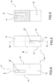
- connection seat (or the aforesaid plurality of connection seats) and the lower end can be coupled with at least two different orientations of the runner 10 with respect to the door leaf 4.
- the runner 10 and the door leaf are shaped so as to present a reversible connection or mounting, variable depending on the spatial orientation of the runner 10.
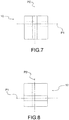
- the runner 10 delimits at least a different friction surface 12, 12', 14, 14' with respect to the translation guide 2, 2' where the friction surfaces 12, 12', 14, 14' are non-equidistant from the support element 20 so that the relative position between the door leaf 4 and the translation guide 2, 2' can be changed by means of the different orientations of said runner 10.
- the door leaf 4 can assume different sliding positions with respect to the translation guide.
- the friction surfaces 12, 12', 14, 14' are in abutment with at least a side wall 26 defining part of the aforesaid longitudinal groove 24.
- each friction surface 12; 12'; 14; 14' and the support element 20 is preferably calibrated in order to adjust the location of the door leaf 4 in a transversal direction T to the main extension of the translation guide 2, 2'.
- the adjustment is made with a range of between 0,5 - 6,0 millimetres.
- the adjustment is made with a pitch of about 0,5 - 1,5 millimetres, preferably 0,8 -1.2 mm, for example about 1,0 millimetre.
- the support element 20 and at least one connection seat 8, 8' of the runner 10 are shaped to be connectable to each other with a first orientation and with a second orientation.
- the runner 10 is rotated with respect to the support element 20 by at least 90° compared to the first orientation, for example approximately 180°.
- such rotation of at least 90° could take place around a vertical axis, or around a main extension axis X of the runner.
- the runner 10 identifies at least a pair of non-coinciding connection seats 8, 8' accessible through opposite ends of such runner 10, for example an upper and lower end according to the arrangement shown in Figure 3 .
- connection between the lower end 6 and one 8 or other 8' connection seat of the runner 10 occurs preferably at least through an up-down reversal of said runner 10.
- such reversal could take place at least around a median axis M of the runner 10.
- connection seat 8, 8' or the plurality thereof comprises a recess 16, 16', which extends at least partly into the body 18 of the runner 10.
- At least part of the support element 20 or the support bracket (where provided) is suitable for being inserted inside such recess 16, 16'.
- the pair of recesses 16, 16' could extend in intersecting planes P1, P2, for example at about 90°.
- the translation guide 2, 2' could be integrated at least in part inside a walkable sill 22, 22' of an elevator car or a landing door.
- said walkable sill could be selected between an aluminium sill, an iron sill or a stainless steel sill.
- the assembly 1 could comprise a car or landing upright, with respect to which the door leaf 4 is movable / slidable.
- the maximum space defined between a front surface of said leaf 4 and said upright is preferably equal to or smaller than about 3 mm.
- the present invention further relates to a runner 10 usable in a guide assembly, preferably in an assembly according to any of the previous embodiments.
- Such runner 10 identifies one or more connection seats 8, 8' to the support element 20, where said seat/s and such end are coupled with at least two different orientations of the runner 10 with respect to the leaf 4.
- the runner 10 delimits at least a different friction surface 12, 12', 14, 14' from the translation guide 2, 2', the friction surfaces 12, 12', 14, 14' being non-equidistant from the at least one connection seat 8, 8' for the support element 20 so that the relative position between the door leaf 4 and the translation guide 2, 2' can be changed by means of the different orientations of said runner 10.
- the runner has been designed so that a single component can resolve a multitude of possible adjustments of a leaf with respect to a guide, merely by means of a different orientation of the runner with respect to the leaf.
- the aforesaid runner is made in one piece together with the necessary connection seat/s, so that it has a very low production cost.
- the assembly and the runner according to the present invention make it possible to achieve excellent assembly tolerances in a variety of different assembly configurations.
- the assembly and the runner according to the present invention make it possible to comply with all applicable safety regulations.
Landscapes
- Elevator Door Apparatuses (AREA)
- Footwear And Its Accessory, Manufacturing Method And Apparatuses (AREA)
- Seats For Vehicles (AREA)
- Closing And Opening Devices For Wings, And Checks For Wings (AREA)
Claims (15)
- Führungsanordnung (1, 1'), umfassend:- eine Translationsführung (2, 2');- ein Türblatt (4) für einen Lift, welches entlang der Translationsführung (2, 2') beweglich ist und wenigstens ein Halterungselement (20) umfasst, welches an einem Ende (6) des Blatts platziert ist;- wenigstens ein Gleitstück (10), welches verschiebbar in der Translationsführung (2, 2') aufgenommen ist,wobei für jede Ausrichtung das Gleitstück (10) wenigstens eine verschiedene Reibfläche (12, 12', 14, 14') in Bezug auf die Translationsführung (2, 2') begrenzt, wobei die Reibflächen (12, 12', 14, 14') von dem Halterungselement (20) nicht-äquidistant sind, so dass die relative Position zwischen dem Türblatt (4) und der Translationsführung (2, 2') mittels der verschiedenen Ausrichtungen des Gleitstücks (10) geändert werden kann.
dadurch gekennzeichnet, dass
wenigstens ein Gleitstück (10) einen oder mehrere Verbindungssitze (8, 8') mit dem Halterungselement (20) definiert, wobei der Sitz / die Sitze und das Element mit wenigstens zwei verschiedenen Ausrichtungen des Gleitstücks (10) in Bezug auf das Türblatt (4) gekoppelt werden können; - Anordnung nach Anspruch 1, wobei die Distanz zwischen jeder Reibfläche (12; 12'; 14; 14') und dem Halterungselement (20) kalibriert wird, um die Lage des Türblatts (4) in einer transversalen Richtung (T) zu der Haupterstreckung der Translationsführung (2, 2') einzustellen.
- Anordnung nach dem vorhergehenden Anspruch, wobei die Einstellung mit einer Abweichung gemacht wird, welche zwischen 0,5 - 6,0 Millimeter, mit einem Abstand von etwa 0,5 - 1,5 Millimeter, umfasst ist.
- Anordnung nach einem der vorhergehenden Ansprüche, wobei das Halterungselement (20) und wenigstens ein Verbindungssitz (8, 8') des Gleitstücks (10) derart geformt sind, dass sie mit einer ersten Ausrichtung und mit einer zweiten Ausrichtung, in welcher das Gleitstück (10) in Bezug auf das Halterungselement (20) um wenigstens 90° zu der ersten Ausrichtung, zum Beispiel etwa 180°, gedreht ist, miteinander verbindbar sind.
- Anordnung nach einem der vorhergehenden Ansprüche, wobei das Gleitstück (10) wenigstens ein Paar nicht miteinander übereinstimmender Verbindungssitze (8, 8') identifiziert, welche durch entgegengesetzte Enden des Gleitstücks (10) erreichbar sind.
- Anordnung nach dem vorhergehenden Anspruch, wobei die Verbindung zwischen dem Halterungselement (20) und einem (8) oder einem anderen (8') Verbindungssitz des Gleitstücks (10) wenigstens durch eine Oben-Unten-Umkehrung des Gleitstücks (10) auftritt.
- Anordnung nach den Ansprüchen 4 oder 6, wobei die Drehung von wenigstens 90° um eine Haupterstreckungsachse (X) des Gleitstücks stattfindet und/oder wobei die Umkehrung wenigstens um eine Medianachse (M) des Gleitstücks (10) stattfindet.
- Anordnung nach einem der vorhergehenden Ansprüche, wobei der Verbindungssitz (8, 8') oder die Mehrzahl davon eine Ausnehmung (16, 16') umfasst, welche sich wenigstens teilweise in den Körper (18) des Gleitstücks (10) erstreckt und in welche wenigstens ein Teil des Halterungselements (20) einsetzbar ist.
- Anordnung nach dem vorhergehenden Anspruch, wenn abhängig von Anspruch 4, wobei sich das Paar von Ausnehmungen (16, 16') in einander schneidenden Ebenen (P1, P2) erstreckt.
- Anordnung nach einem der vorhergehenden Ansprüche, wobei das Halterungselement (20) wenigstens einen oder mehrere Halterungsträger für das Gleitstück (10) umfasst, wobei der Träger in einer in Richtung der Translationsführung (2, 2') vorstehenden Weise an dem unteren Ende (6) montiert oder daran geschweißt ist.
- Anordnung nach einem der vorhergehenden Ansprüche, wobei das Gleitstück (10) wenigstens teilweise, zum Beispiel vollständig, aus einem polymeren Material hergestellt ist.
- Anordnung nach einem der vorhergehenden Ansprüche, wobei das Gleitstück (10) im Wesentlichen in Form eines Parallelepipeds, insbesondere in der Form eines rechteckigen Parallelepipeds, vorliegt.
- Anordnung nach einem der vorhergehenden Ansprüche, wobei die Translationsführung (2, 2') wenigstens teilweise in einer begehbaren Schwelle (22, 22') einer Aufzugskabine oder einer Schachttür integriert ist, wobei die begehbare Schwelle zwischen einer Aluminiumschwelle, einer Eisenschwelle oder einer Schwelle aus rostfreiem Stahl ausgewählt ist.
- Anordnung nach einem der vorhergehenden Ansprüche, umfassend einen Kabinen- oder Schachtpfosten, in Bezug auf welchen das Türblatt (4) beweglich ist, wobei der maximale Raum, welcher zwischen einer vorderen Fläche des Türblatts (4) und dem Pfosten definiert ist, gleich oder kleiner als 3 Millimeter ist.
- Gleitstück (10), welches in einer Führungsanordnung verwendbar ist;
wobei die Führungsanordnung (1, 1') eine Translationsführung (2, 2'), und ein Türblatt (4) für einen Lift umfasst, welches entlang der Translationsführung (2, 2') beweglich ist und wenigstens ein Halterungselement (20) umfasst, welches an einem Ende (6) des Blatts platziert ist, und wenigstens eines der Gleitstücke verschiebbar in der Translationsführung (2, 2') aufgenommen ist,
dadurch gekennzeichnet, dass
das Gleitstück (10) einen oder mehrere Verbindungssitze (8, 8') mit dem Halterungselement (20) definiert, wobei der Sitz / die Sitze und das Element mit wenigstens zwei verschiedenen Ausrichtungen des Gleitstücks (10) in Bezug auf das Türblatt (4) gekoppelt sind;
wobei für jede Ausrichtung das Gleitstück (10) wenigstens eine verschiedene Reibfläche (12, 12', 14, 14') von der Translationsführung (2, 2') begrenzt, wobei die Reibflächen (12, 12', 14, 14') von dem wenigstens einen Verbindungssitz (8, 8') für das Halterungselement (20) nicht-äquidistant sind, so dass die relative Position zwischen dem Türblatt (4) und der Translationsführung (2, 2') mittels der verschiedenen Ausrichtungen des Gleitstücks (10) geändert werden kann.
Applications Claiming Priority (2)
| Application Number | Priority Date | Filing Date | Title |
|---|---|---|---|
| ITUB2015A005634A ITUB20155634A1 (it) | 2015-11-17 | 2015-11-17 | Assieme di guida e pattino |
| PCT/IB2016/056689 WO2017085585A1 (en) | 2015-11-17 | 2016-11-07 | Guide assembly and runner |
Publications (2)
| Publication Number | Publication Date |
|---|---|
| EP3377435A1 EP3377435A1 (de) | 2018-09-26 |
| EP3377435B1 true EP3377435B1 (de) | 2020-06-17 |
Family
ID=55485101
Family Applications (1)
| Application Number | Title | Priority Date | Filing Date |
|---|---|---|---|
| EP16810467.7A Active EP3377435B1 (de) | 2015-11-17 | 2016-11-07 | Führungsanordnung und laufer |
Country Status (6)
| Country | Link |
|---|---|
| US (1) | US10793397B2 (de) |
| EP (1) | EP3377435B1 (de) |
| CN (1) | CN108473282B (de) |
| ES (1) | ES2817750T3 (de) |
| IT (1) | ITUB20155634A1 (de) |
| WO (1) | WO2017085585A1 (de) |
Families Citing this family (1)
| Publication number | Priority date | Publication date | Assignee | Title |
|---|---|---|---|---|
| ITUB20155634A1 (it) * | 2015-11-17 | 2017-05-17 | Sematic S P A | Assieme di guida e pattino |
Family Cites Families (39)
| Publication number | Priority date | Publication date | Assignee | Title |
|---|---|---|---|---|
| US3195171A (en) * | 1963-03-21 | 1965-07-20 | Robert I Klein | Door guide |
| JPH02282181A (ja) * | 1989-04-20 | 1990-11-19 | Toshiba Corp | エレベータドアのガイドシュー |
| US5174675A (en) * | 1990-05-07 | 1992-12-29 | Inventio Ag | Guide bar for an elevator door |
| JPH04182294A (ja) * | 1990-11-19 | 1992-06-29 | Hitachi Building Syst Eng & Service Co Ltd | エレベータ乗場上開きドア |
| JPH07237867A (ja) * | 1994-03-01 | 1995-09-12 | Hitachi Ltd | エレベータ扉の案内装置 |
| US5706913A (en) * | 1995-10-31 | 1998-01-13 | Otis Elevator Company | Guide assembly for an elevator door |
| CN1107776C (zh) * | 1997-06-11 | 2003-05-07 | Cds努-钢铁有限公司 | 建筑框架系统 |
| JPH1135261A (ja) * | 1997-07-22 | 1999-02-09 | Mitsubishi Denki Bill Techno Service Kk | エレベータ用ドア |
| US6247557B1 (en) * | 1998-04-28 | 2001-06-19 | Kabushiki Kaisha Toshiba | Traction type elevator apparatus |
| US5901525A (en) * | 1998-11-13 | 1999-05-11 | Robert L. Consolini | Elevated base for column support |
| JP2000226176A (ja) * | 1999-02-05 | 2000-08-15 | Mitsubishi Electric Building Techno Service Co Ltd | エレベータの戸装置の異常検出装置 |
| JP2001247283A (ja) * | 2000-03-06 | 2001-09-11 | Toshiba Elevator Co Ltd | エレベータ用ドア |
| US6684573B2 (en) * | 2001-05-04 | 2004-02-03 | Thyssen Elevator Capital Corp. | Elevator door sill assembly |
| US7044773B2 (en) * | 2002-08-01 | 2006-05-16 | Ddk Ltd. | Connector |
| JP2004099265A (ja) * | 2002-09-11 | 2004-04-02 | Toshiba Elevator Co Ltd | エレベータ扉のガイド装置およびエレベータ扉 |
| JP2004244155A (ja) * | 2003-02-13 | 2004-09-02 | Mitsubishi Electric Corp | エレベータ用引き戸装置及び引き戸用ガイド脚 |
| JP2005082315A (ja) * | 2003-09-08 | 2005-03-31 | Toshiba Elevator Co Ltd | エレベータのドア装置 |
| WO2005030629A1 (ja) * | 2003-09-30 | 2005-04-07 | Toshiba Elevator Kabushiki Kaisha | エレベータの防災装置 |
| JP2006131314A (ja) * | 2004-11-02 | 2006-05-25 | Toshiba Elevator Co Ltd | エレベータのドア装置 |
| JP2006206216A (ja) * | 2005-01-26 | 2006-08-10 | Mitsubishi Electric Corp | エレベータの戸の案内装置 |
| CN2826055Y (zh) * | 2005-11-21 | 2006-10-11 | 深圳市裕佳康精密科技有限公司 | 一种直线金属导轨 |
| JP2007161451A (ja) * | 2005-12-15 | 2007-06-28 | Mitsubishi Electric Corp | 間隔調節装置 |
| CN2911304Y (zh) * | 2006-04-15 | 2007-06-13 | 周景虎 | 一种平直轴承 |
| US8181394B2 (en) * | 2007-05-03 | 2012-05-22 | Donald Charles Michaels | Reinforced elevator door guide |
| CN201281083Y (zh) * | 2008-03-30 | 2009-07-29 | 宋哲平 | 一种导向滑块组件 |
| KR101273839B1 (ko) * | 2008-04-18 | 2013-06-11 | 미쓰비시덴키 가부시키가이샤 | 엘리베이터의 승장 도어 이탈 방지 구조 |
| FI122480B (fi) * | 2009-09-03 | 2012-02-15 | Kone Corp | Ovijärjestely ja oven ohjain |
| CN201792179U (zh) * | 2010-08-31 | 2011-04-13 | 南通通洋机电制造有限公司 | 导靴对称安装工具 |
| CN202851646U (zh) * | 2012-10-31 | 2013-04-03 | 宁波三泰轴承有限公司 | 一种滑块导轨装置 |
| JP5826315B2 (ja) * | 2014-02-28 | 2015-12-02 | 東芝エレベータ株式会社 | エレベータのガイドシュー |
| CN204188134U (zh) * | 2014-04-03 | 2015-03-04 | 东莞市天勤仪器有限公司 | 预紧力可调式滑块及预紧力可调式滑动装置 |
| CN204007963U (zh) * | 2014-07-23 | 2014-12-10 | 中国工程物理研究院化工材料研究所 | 一种用于微力矩测试系统的可调工装 |
| JP6341453B2 (ja) * | 2014-12-22 | 2018-06-13 | フジテック株式会社 | エレベータの敷居清掃装置および取付治具 |
| US10308481B2 (en) * | 2015-03-19 | 2019-06-04 | Wittur Holding Gmbh | Elevator door and method for opening an elevator door having two sliding door panels |
| CN205114786U (zh) * | 2015-10-16 | 2016-03-30 | 日立电梯(上海)有限公司 | 一种电梯厅门防脱装置 |
| ITUB20155634A1 (it) * | 2015-11-17 | 2017-05-17 | Sematic S P A | Assieme di guida e pattino |
| CN107285175A (zh) * | 2016-04-13 | 2017-10-24 | 奥的斯电梯公司 | 电梯厅门总成和电梯系统 |
| CN207986473U (zh) * | 2017-12-11 | 2018-10-19 | 奥的斯电梯公司 | 电梯厅门系统下导向总成和电梯系统 |
| EP3543445A1 (de) * | 2018-03-21 | 2019-09-25 | Otis Elevator Company | Schiebetürsystem |
-
2015
- 2015-11-17 IT ITUB2015A005634A patent/ITUB20155634A1/it unknown
-
2016
- 2016-11-07 ES ES16810467T patent/ES2817750T3/es active Active
- 2016-11-07 WO PCT/IB2016/056689 patent/WO2017085585A1/en not_active Ceased
- 2016-11-07 EP EP16810467.7A patent/EP3377435B1/de active Active
- 2016-11-07 CN CN201680066998.2A patent/CN108473282B/zh active Active
- 2016-11-07 US US15/776,411 patent/US10793397B2/en active Active
Non-Patent Citations (1)
| Title |
|---|
| None * |
Also Published As
| Publication number | Publication date |
|---|---|
| US10793397B2 (en) | 2020-10-06 |
| US20180297818A1 (en) | 2018-10-18 |
| CN108473282A (zh) | 2018-08-31 |
| EP3377435A1 (de) | 2018-09-26 |
| CN108473282B (zh) | 2020-10-23 |
| ES2817750T3 (es) | 2021-04-08 |
| ITUB20155634A1 (it) | 2017-05-17 |
| WO2017085585A1 (en) | 2017-05-26 |
Similar Documents
| Publication | Publication Date | Title |
|---|---|---|
| EP3094165B1 (de) | Gleitschienenanordnung | |
| EP3224184B1 (de) | Verfahren zur herstellung einer schwelle für eine aufzugstür und schwelle | |
| EP1981369B1 (de) | Teleskophebesäule für höhenverstellbare tische | |
| US8960802B2 (en) | Vehicle seat with guided scissor arms | |
| CN104071039A (zh) | 座椅轨道端盖和行进阻挡座椅位置传感器 | |
| EP3326909B1 (de) | Vorflügelanordnung | |
| CN103307069A (zh) | 多节可伸缩装置 | |
| US9481555B2 (en) | Industrial truck having an overhead guard | |
| CA3023503C (en) | Removable profile structure | |
| EP3082386B1 (de) | Montagevorrichtung | |
| CN101100258B (zh) | 用于电梯的导轨 | |
| US10117352B2 (en) | Slide rail assembly | |
| EP3323314A1 (de) | Schnellkupplung von laufschiene | |
| EP1927770A3 (de) | Lineareinheit | |
| US10793397B2 (en) | Guide assemblies and runners | |
| EP3582653B1 (de) | Verbessertes frontregelungssystem für stellfüsse für möbel | |
| US20120193493A1 (en) | Rail vehicle having an installation housing secured by means of a bracket | |
| CN103547469B (zh) | 用于安装车顶的可移动顶棚元件的滑动单元以及车顶 | |
| US10099860B2 (en) | Connecting device, conveying carriage and conveying installation | |
| EP1970515A3 (de) | Schiebe- und Verriegelungsvorrichtung | |
| EP3280673B1 (de) | System und verfahren für sicherheitsgetriebeausrichtung für einen aufzug | |
| CN204237397U (zh) | 一种可调式新型电梯轿厢导轨支架 | |
| EP2629645B1 (de) | Verbesserungen an und im zusammenhang mit teleskopischen doppellaufschienen | |
| EP2431318B1 (de) | Schließsysteme für bewegliche Plattformen | |
| EP2187134B1 (de) | Ofen, insbesondere Haushaltsofen |
Legal Events
| Date | Code | Title | Description |
|---|---|---|---|
| STAA | Information on the status of an ep patent application or granted ep patent |
Free format text: STATUS: UNKNOWN |
|
| STAA | Information on the status of an ep patent application or granted ep patent |
Free format text: STATUS: THE INTERNATIONAL PUBLICATION HAS BEEN MADE |
|
| PUAI | Public reference made under article 153(3) epc to a published international application that has entered the european phase |
Free format text: ORIGINAL CODE: 0009012 |
|
| STAA | Information on the status of an ep patent application or granted ep patent |
Free format text: STATUS: REQUEST FOR EXAMINATION WAS MADE |
|
| 17P | Request for examination filed |
Effective date: 20180509 |
|
| AK | Designated contracting states |
Kind code of ref document: A1 Designated state(s): AL AT BE BG CH CY CZ DE DK EE ES FI FR GB GR HR HU IE IS IT LI LT LU LV MC MK MT NL NO PL PT RO RS SE SI SK SM TR |
|
| AX | Request for extension of the european patent |
Extension state: BA ME |
|
| DAV | Request for validation of the european patent (deleted) | ||
| DAX | Request for extension of the european patent (deleted) | ||
| GRAP | Despatch of communication of intention to grant a patent |
Free format text: ORIGINAL CODE: EPIDOSNIGR1 |
|
| STAA | Information on the status of an ep patent application or granted ep patent |
Free format text: STATUS: GRANT OF PATENT IS INTENDED |
|
| INTG | Intention to grant announced |
Effective date: 20200305 |
|
| GRAS | Grant fee paid |
Free format text: ORIGINAL CODE: EPIDOSNIGR3 |
|
| GRAA | (expected) grant |
Free format text: ORIGINAL CODE: 0009210 |
|
| STAA | Information on the status of an ep patent application or granted ep patent |
Free format text: STATUS: THE PATENT HAS BEEN GRANTED |
|
| AK | Designated contracting states |
Kind code of ref document: B1 Designated state(s): AL AT BE BG CH CY CZ DE DK EE ES FI FR GB GR HR HU IE IS IT LI LT LU LV MC MK MT NL NO PL PT RO RS SE SI SK SM TR |
|
| REG | Reference to a national code |
Ref country code: GB Ref legal event code: FG4D |
|
| REG | Reference to a national code |
Ref country code: CH Ref legal event code: EP |
|
| REG | Reference to a national code |
Ref country code: IE Ref legal event code: FG4D |
|
| REG | Reference to a national code |
Ref country code: DE Ref legal event code: R096 Ref document number: 602016038393 Country of ref document: DE |
|
| REG | Reference to a national code |
Ref country code: AT Ref legal event code: REF Ref document number: 1281066 Country of ref document: AT Kind code of ref document: T Effective date: 20200715 |
|
| REG | Reference to a national code |
Ref country code: CH Ref legal event code: NV Representative=s name: VALIPAT S.A. C/O BOVARD SA NEUCHATEL, CH |
|
| PG25 | Lapsed in a contracting state [announced via postgrant information from national office to epo] |
Ref country code: LT Free format text: LAPSE BECAUSE OF FAILURE TO SUBMIT A TRANSLATION OF THE DESCRIPTION OR TO PAY THE FEE WITHIN THE PRESCRIBED TIME-LIMIT Effective date: 20200617 Ref country code: GR Free format text: LAPSE BECAUSE OF FAILURE TO SUBMIT A TRANSLATION OF THE DESCRIPTION OR TO PAY THE FEE WITHIN THE PRESCRIBED TIME-LIMIT Effective date: 20200918 Ref country code: NO Free format text: LAPSE BECAUSE OF FAILURE TO SUBMIT A TRANSLATION OF THE DESCRIPTION OR TO PAY THE FEE WITHIN THE PRESCRIBED TIME-LIMIT Effective date: 20200917 Ref country code: SE Free format text: LAPSE BECAUSE OF FAILURE TO SUBMIT A TRANSLATION OF THE DESCRIPTION OR TO PAY THE FEE WITHIN THE PRESCRIBED TIME-LIMIT Effective date: 20200617 Ref country code: FI Free format text: LAPSE BECAUSE OF FAILURE TO SUBMIT A TRANSLATION OF THE DESCRIPTION OR TO PAY THE FEE WITHIN THE PRESCRIBED TIME-LIMIT Effective date: 20200617 |
|
| REG | Reference to a national code |
Ref country code: LT Ref legal event code: MG4D |
|
| REG | Reference to a national code |
Ref country code: NL Ref legal event code: MP Effective date: 20200617 |
|
| PG25 | Lapsed in a contracting state [announced via postgrant information from national office to epo] |
Ref country code: HR Free format text: LAPSE BECAUSE OF FAILURE TO SUBMIT A TRANSLATION OF THE DESCRIPTION OR TO PAY THE FEE WITHIN THE PRESCRIBED TIME-LIMIT Effective date: 20200617 Ref country code: RS Free format text: LAPSE BECAUSE OF FAILURE TO SUBMIT A TRANSLATION OF THE DESCRIPTION OR TO PAY THE FEE WITHIN THE PRESCRIBED TIME-LIMIT Effective date: 20200617 Ref country code: LV Free format text: LAPSE BECAUSE OF FAILURE TO SUBMIT A TRANSLATION OF THE DESCRIPTION OR TO PAY THE FEE WITHIN THE PRESCRIBED TIME-LIMIT Effective date: 20200617 Ref country code: BG Free format text: LAPSE BECAUSE OF FAILURE TO SUBMIT A TRANSLATION OF THE DESCRIPTION OR TO PAY THE FEE WITHIN THE PRESCRIBED TIME-LIMIT Effective date: 20200917 |
|
| REG | Reference to a national code |
Ref country code: AT Ref legal event code: MK05 Ref document number: 1281066 Country of ref document: AT Kind code of ref document: T Effective date: 20200617 |
|
| PG25 | Lapsed in a contracting state [announced via postgrant information from national office to epo] |
Ref country code: AL Free format text: LAPSE BECAUSE OF FAILURE TO SUBMIT A TRANSLATION OF THE DESCRIPTION OR TO PAY THE FEE WITHIN THE PRESCRIBED TIME-LIMIT Effective date: 20200617 Ref country code: NL Free format text: LAPSE BECAUSE OF FAILURE TO SUBMIT A TRANSLATION OF THE DESCRIPTION OR TO PAY THE FEE WITHIN THE PRESCRIBED TIME-LIMIT Effective date: 20200617 |
|
| PG25 | Lapsed in a contracting state [announced via postgrant information from national office to epo] |
Ref country code: EE Free format text: LAPSE BECAUSE OF FAILURE TO SUBMIT A TRANSLATION OF THE DESCRIPTION OR TO PAY THE FEE WITHIN THE PRESCRIBED TIME-LIMIT Effective date: 20200617 Ref country code: PT Free format text: LAPSE BECAUSE OF FAILURE TO SUBMIT A TRANSLATION OF THE DESCRIPTION OR TO PAY THE FEE WITHIN THE PRESCRIBED TIME-LIMIT Effective date: 20201019 Ref country code: CZ Free format text: LAPSE BECAUSE OF FAILURE TO SUBMIT A TRANSLATION OF THE DESCRIPTION OR TO PAY THE FEE WITHIN THE PRESCRIBED TIME-LIMIT Effective date: 20200617 Ref country code: RO Free format text: LAPSE BECAUSE OF FAILURE TO SUBMIT A TRANSLATION OF THE DESCRIPTION OR TO PAY THE FEE WITHIN THE PRESCRIBED TIME-LIMIT Effective date: 20200617 Ref country code: AT Free format text: LAPSE BECAUSE OF FAILURE TO SUBMIT A TRANSLATION OF THE DESCRIPTION OR TO PAY THE FEE WITHIN THE PRESCRIBED TIME-LIMIT Effective date: 20200617 Ref country code: SM Free format text: LAPSE BECAUSE OF FAILURE TO SUBMIT A TRANSLATION OF THE DESCRIPTION OR TO PAY THE FEE WITHIN THE PRESCRIBED TIME-LIMIT Effective date: 20200617 |
|
| PG25 | Lapsed in a contracting state [announced via postgrant information from national office to epo] |
Ref country code: PL Free format text: LAPSE BECAUSE OF FAILURE TO SUBMIT A TRANSLATION OF THE DESCRIPTION OR TO PAY THE FEE WITHIN THE PRESCRIBED TIME-LIMIT Effective date: 20200617 Ref country code: SK Free format text: LAPSE BECAUSE OF FAILURE TO SUBMIT A TRANSLATION OF THE DESCRIPTION OR TO PAY THE FEE WITHIN THE PRESCRIBED TIME-LIMIT Effective date: 20200617 Ref country code: IS Free format text: LAPSE BECAUSE OF FAILURE TO SUBMIT A TRANSLATION OF THE DESCRIPTION OR TO PAY THE FEE WITHIN THE PRESCRIBED TIME-LIMIT Effective date: 20201017 |
|
| REG | Reference to a national code |
Ref country code: DE Ref legal event code: R097 Ref document number: 602016038393 Country of ref document: DE |
|
| REG | Reference to a national code |
Ref country code: ES Ref legal event code: FG2A Ref document number: 2817750 Country of ref document: ES Kind code of ref document: T3 Effective date: 20210408 |
|
| PLBE | No opposition filed within time limit |
Free format text: ORIGINAL CODE: 0009261 |
|
| STAA | Information on the status of an ep patent application or granted ep patent |
Free format text: STATUS: NO OPPOSITION FILED WITHIN TIME LIMIT |
|
| PG25 | Lapsed in a contracting state [announced via postgrant information from national office to epo] |
Ref country code: DK Free format text: LAPSE BECAUSE OF FAILURE TO SUBMIT A TRANSLATION OF THE DESCRIPTION OR TO PAY THE FEE WITHIN THE PRESCRIBED TIME-LIMIT Effective date: 20200617 |
|
| 26N | No opposition filed |
Effective date: 20210318 |
|
| PG25 | Lapsed in a contracting state [announced via postgrant information from national office to epo] |
Ref country code: SI Free format text: LAPSE BECAUSE OF FAILURE TO SUBMIT A TRANSLATION OF THE DESCRIPTION OR TO PAY THE FEE WITHIN THE PRESCRIBED TIME-LIMIT Effective date: 20200617 |
|
| PG25 | Lapsed in a contracting state [announced via postgrant information from national office to epo] |
Ref country code: MC Free format text: LAPSE BECAUSE OF FAILURE TO SUBMIT A TRANSLATION OF THE DESCRIPTION OR TO PAY THE FEE WITHIN THE PRESCRIBED TIME-LIMIT Effective date: 20200617 |
|
| PG25 | Lapsed in a contracting state [announced via postgrant information from national office to epo] |
Ref country code: LU Free format text: LAPSE BECAUSE OF NON-PAYMENT OF DUE FEES Effective date: 20201107 |
|
| REG | Reference to a national code |
Ref country code: BE Ref legal event code: MM Effective date: 20201130 |
|
| PG25 | Lapsed in a contracting state [announced via postgrant information from national office to epo] |
Ref country code: IE Free format text: LAPSE BECAUSE OF NON-PAYMENT OF DUE FEES Effective date: 20201107 |
|
| PG25 | Lapsed in a contracting state [announced via postgrant information from national office to epo] |
Ref country code: MT Free format text: LAPSE BECAUSE OF FAILURE TO SUBMIT A TRANSLATION OF THE DESCRIPTION OR TO PAY THE FEE WITHIN THE PRESCRIBED TIME-LIMIT Effective date: 20200617 Ref country code: CY Free format text: LAPSE BECAUSE OF FAILURE TO SUBMIT A TRANSLATION OF THE DESCRIPTION OR TO PAY THE FEE WITHIN THE PRESCRIBED TIME-LIMIT Effective date: 20200617 |
|
| PG25 | Lapsed in a contracting state [announced via postgrant information from national office to epo] |
Ref country code: MK Free format text: LAPSE BECAUSE OF FAILURE TO SUBMIT A TRANSLATION OF THE DESCRIPTION OR TO PAY THE FEE WITHIN THE PRESCRIBED TIME-LIMIT Effective date: 20200617 |
|
| PG25 | Lapsed in a contracting state [announced via postgrant information from national office to epo] |
Ref country code: BE Free format text: LAPSE BECAUSE OF NON-PAYMENT OF DUE FEES Effective date: 20201130 |
|
| PGFP | Annual fee paid to national office [announced via postgrant information from national office to epo] |
Ref country code: TR Payment date: 20221107 Year of fee payment: 7 Ref country code: GB Payment date: 20221125 Year of fee payment: 7 Ref country code: FR Payment date: 20221122 Year of fee payment: 7 Ref country code: ES Payment date: 20221201 Year of fee payment: 7 |
|
| PGFP | Annual fee paid to national office [announced via postgrant information from national office to epo] |
Ref country code: CH Payment date: 20221114 Year of fee payment: 7 |
|
| REG | Reference to a national code |
Ref country code: CH Ref legal event code: PL |
|
| PG25 | Lapsed in a contracting state [announced via postgrant information from national office to epo] |
Ref country code: CH Free format text: LAPSE BECAUSE OF NON-PAYMENT OF DUE FEES Effective date: 20231130 |
|
| GBPC | Gb: european patent ceased through non-payment of renewal fee |
Effective date: 20231107 |
|
| PG25 | Lapsed in a contracting state [announced via postgrant information from national office to epo] |
Ref country code: CH Free format text: LAPSE BECAUSE OF NON-PAYMENT OF DUE FEES Effective date: 20231130 |
|
| PG25 | Lapsed in a contracting state [announced via postgrant information from national office to epo] |
Ref country code: GB Free format text: LAPSE BECAUSE OF NON-PAYMENT OF DUE FEES Effective date: 20231107 |
|
| PG25 | Lapsed in a contracting state [announced via postgrant information from national office to epo] |
Ref country code: FR Free format text: LAPSE BECAUSE OF NON-PAYMENT OF DUE FEES Effective date: 20231130 |
|
| PG25 | Lapsed in a contracting state [announced via postgrant information from national office to epo] |
Ref country code: FR Free format text: LAPSE BECAUSE OF NON-PAYMENT OF DUE FEES Effective date: 20231130 Ref country code: GB Free format text: LAPSE BECAUSE OF NON-PAYMENT OF DUE FEES Effective date: 20231107 |
|
| REG | Reference to a national code |
Ref country code: ES Ref legal event code: FD2A Effective date: 20250102 |
|
| PG25 | Lapsed in a contracting state [announced via postgrant information from national office to epo] |
Ref country code: ES Free format text: LAPSE BECAUSE OF NON-PAYMENT OF DUE FEES Effective date: 20231108 |
|
| PG25 | Lapsed in a contracting state [announced via postgrant information from national office to epo] |
Ref country code: ES Free format text: LAPSE BECAUSE OF NON-PAYMENT OF DUE FEES Effective date: 20231108 |
|
| PGFP | Annual fee paid to national office [announced via postgrant information from national office to epo] |
Ref country code: DE Payment date: 20251126 Year of fee payment: 10 |
|
| PGFP | Annual fee paid to national office [announced via postgrant information from national office to epo] |
Ref country code: IT Payment date: 20251127 Year of fee payment: 10 |