EP3582653B1 - Verbessertes frontregelungssystem für stellfüsse für möbel - Google Patents
Verbessertes frontregelungssystem für stellfüsse für möbel Download PDFInfo
- Publication number
- EP3582653B1 EP3582653B1 EP18703349.3A EP18703349A EP3582653B1 EP 3582653 B1 EP3582653 B1 EP 3582653B1 EP 18703349 A EP18703349 A EP 18703349A EP 3582653 B1 EP3582653 B1 EP 3582653B1
- Authority
- EP
- European Patent Office
- Prior art keywords
- feet
- furniture
- foot
- supporting
- axis
- Prior art date
- Legal status (The legal status is an assumption and is not a legal conclusion. Google has not performed a legal analysis and makes no representation as to the accuracy of the status listed.)
- Active
Links
Images

Classifications
-
- A—HUMAN NECESSITIES
- A47—FURNITURE; DOMESTIC ARTICLES OR APPLIANCES; COFFEE MILLS; SPICE MILLS; SUCTION CLEANERS IN GENERAL
- A47B—TABLES; DESKS; OFFICE FURNITURE; CABINETS; DRAWERS; GENERAL DETAILS OF FURNITURE
- A47B91/00—Feet for furniture in general
- A47B91/02—Adjustable feet
-
- A—HUMAN NECESSITIES
- A47—FURNITURE; DOMESTIC ARTICLES OR APPLIANCES; COFFEE MILLS; SPICE MILLS; SUCTION CLEANERS IN GENERAL
- A47B—TABLES; DESKS; OFFICE FURNITURE; CABINETS; DRAWERS; GENERAL DETAILS OF FURNITURE
- A47B91/00—Feet for furniture in general
- A47B91/02—Adjustable feet
- A47B91/022—Adjustable feet using screw means
- A47B91/028—Means for rotational adjustment on a non-rotational foot
-
- A—HUMAN NECESSITIES
- A47—FURNITURE; DOMESTIC ARTICLES OR APPLIANCES; COFFEE MILLS; SPICE MILLS; SUCTION CLEANERS IN GENERAL
- A47B—TABLES; DESKS; OFFICE FURNITURE; CABINETS; DRAWERS; GENERAL DETAILS OF FURNITURE
- A47B97/00—Furniture or accessories for furniture, not provided for in other groups of this subclass
-
- A—HUMAN NECESSITIES
- A47—FURNITURE; DOMESTIC ARTICLES OR APPLIANCES; COFFEE MILLS; SPICE MILLS; SUCTION CLEANERS IN GENERAL
- A47B—TABLES; DESKS; OFFICE FURNITURE; CABINETS; DRAWERS; GENERAL DETAILS OF FURNITURE
- A47B2220/00—General furniture construction, e.g. fittings
- A47B2220/0027—Feet
-
- A—HUMAN NECESSITIES
- A47—FURNITURE; DOMESTIC ARTICLES OR APPLIANCES; COFFEE MILLS; SPICE MILLS; SUCTION CLEANERS IN GENERAL
- A47L—DOMESTIC WASHING OR CLEANING; SUCTION CLEANERS IN GENERAL
- A47L15/00—Washing or rinsing machines for crockery or tableware
- A47L15/42—Details
- A47L15/4251—Details of the casing
- A47L15/4253—Supporting arrangements for the casing, e.g. rollers or supporting legs
-
- D—TEXTILES; PAPER
- D06—TREATMENT OF TEXTILES OR THE LIKE; LAUNDERING; FLEXIBLE MATERIALS NOT OTHERWISE PROVIDED FOR
- D06F—LAUNDERING, DRYING, IRONING, PRESSING OR FOLDING TEXTILE ARTICLES
- D06F39/00—Details of washing machines not specific to a single type of machines covered by groups D06F9/00 - D06F27/00
- D06F39/12—Casings; Tubs
- D06F39/125—Supporting arrangements for the casing, e.g. rollers or legs
-
- F—MECHANICAL ENGINEERING; LIGHTING; HEATING; WEAPONS; BLASTING
- F16—ENGINEERING ELEMENTS AND UNITS; GENERAL MEASURES FOR PRODUCING AND MAINTAINING EFFECTIVE FUNCTIONING OF MACHINES OR INSTALLATIONS; THERMAL INSULATION IN GENERAL
- F16M—FRAMES, CASINGS OR BEDS OF ENGINES, MACHINES OR APPARATUS, NOT SPECIFIC TO ENGINES, MACHINES OR APPARATUS PROVIDED FOR ELSEWHERE; STANDS; SUPPORTS
- F16M7/00—Details of attaching or adjusting engine beds, frames, or supporting-legs on foundation or base; Attaching non-moving engine parts, e.g. cylinder blocks
Definitions
- the present invention relates to an improved front adjustment system for leveling feet for furniture.
- the invention is particularly suitable for effecting the adjustment of rear feet applied to the bottom of the furniture, such as, for example, in kitchen bases, where the distance between the bottom and the floor is minimal and limited, with difficulty of front access to the rear feet of the system.
- feet are currently provided in plaques or attachments for supporting the feet, whereby said plaques are provided with specific passages and housings designed for accommodating the above-mentioned transmission rods towards the rear feet, as disclosed, for example, in Italian patent application MI2011A001872 .
- the separate supports of the transmission rods the supporting plaques of the front feet must in any case provide passages and housings for the transmission rods.
- Italian patent application 102016000024683 describes a compact front adjustment system for leveling feet of furniture (M) with a bottom (12) and shoulders (11), of the type comprising, in combination: at least one front foot (13, 26, 127) and at least one rear foot (16, 27), wherein at least said rear foot (16, 27) comprises an adjustment mechanism in height that is accessible from outside the foot and can be operated by means of a tool (22, 48, 123).
- Said at least one front foot (13, 26, 127) provides a pass-through hole (20, 41, 41', 141', 42, 43) for said adjustment tool of said at least one rear foot (16, 27), wherein said pass-through hole acts as support and guide for said tool.
- the general objective of the present invention is to provide a front adjustment system for rear leveling feet for furniture which is particularly simplified with respect to systems currently known, and therefore very economical.
- a further objective of the present invention is to provide a front adjustment system for rear leveling feet for furniture in which the space beneath the bottom is extremely limited with serious difficulties of access.
- Another objective of the invention is to provide an adjustment system which is suitable for the various configurations of rear feet used for leveling the piece of furniture.
- Yet another objective is to provide a front adjustment system for rear leveling feet for furniture that does not provide any transmission rod for actuating the adjustment of the rear feet of the furniture.
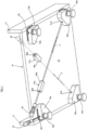
- the figures partially illustrate a piece of furniture M, for example a piece of kitchen furniture (base), in which, in the example shown, shoulders 11 (sides) terminate in correspondence with a bottom 12, i.e. they do not reach the floor (not shown).
- base for example a piece of kitchen furniture (base)
- shoulders 11 sides terminate in correspondence with a bottom 12, i.e. they do not reach the floor (not shown).
- the shoulders 11 can reach the floor and the bottom 12 can be at a greater height with respect to the edge of the shoulders 11 that rest on the floor.
- the furniture (base) M is designed for resting on the floor using at least a pair of front feet 13d, 13s, right and left respectively, and at least a pair of rear feet 14d, 14s.
- Said pairs of front feet 13d, 13s and rear feet 14d, 14s are provided with respective attachments 15d, 15s and 16d, 16s to the bottom 12 of the furniture M itself, in an angular position.
- Said feet and attachments can be of a type well-known to skilled persons in the field, also incorporating an adjustment mechanism in height. Reference should be made, for example, to the above-mentioned prior patents.
- respective supporting and guiding units 17d, 17s for a maneuvering tool 18 cooperate with said pair of rear feet 14d, 14s.
- Said units 17d, 17s are fixed to the bottom 12 of the furniture M (on the outer surface opposed to the floor, not shown) in intermediate positions between the above-mentioned front feet 13d, 13s.
- the units 17d, 17s consist of supporting and guiding elements 19d, 19s, having an elongated parallelepiped form (dowels), crossed by respective longitudinal pass-through holes 20d, 20s.
- the longitudinal symmetry axis of said pass-through holes 20d, 20s coincides and is aligned with the symmetry axis X (it lies along the same axis X) of the holes 21d, 21s of the rear attachments 16d, 16s for access to the adjustment mechanism in height (not shown) of the respective rear foot 14d, 14s.
- the adjustment in height of the rear feet 14d, 14s can be easily effected by introducing the maneuvering tool 18 into the longitudinal holes 20d, 20s and pushing it forwards until it is inserted inside the access holes 21d, 21s to the adjustment mechanism, as clearly illustrated in figure 1 of the drawings.
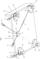
- FIG. 2 of the drawings a single supporting and guiding unit 22 for the maneuvering tool 18 is illustrated, said unit 22 is fixed to the bottom 12 in an intermediate position between the right and left front feet.
- Said unit 22 consists of an element (dowel) generally prismatic 23 in which crossed pass-through holes (a pair) 24d, 24s are formed.
- the longitudinal symmetry axis of said pass-through holes 24d, 24s coincides and is aligned with the symmetry axis X (it lies along the same axis X) of the holes 21d, 21s of the rear attachments 16d, 16s for access to the adjustment mechanism in height (not shown) of the respective rear foot 14d, 14s.
- a single supporting and guiding unit 25 for the maneuvering tool 18 is illustrated, said unit 25 is fixed to the bottom 12 in an intermediate position between the right and left front feet.
- Said unit 25 consists of a supporting and guiding element 26 having an elongated parallelepiped form, crossed by a longitudinal pass-through hole 27.
- Said element 26 is hinged in 28 to a base 29 which is fixed to the bottom 12.
- the element 26 can be rotated between two terminal operating positions determined by a stop 30 of the base 29.
- the longitudinal symmetry axis of said pass-through hole 27 coincides and is aligned with the symmetry axis X (it lies along the same axis X) of the holes 21d, 21s of the rear attachments 16d, 16s for access to the adjustment mechanism in height of the respective rear foot 14d, 14s.
- the adjustment is effected as already explained with reference to figures 1 and 2 , but also causing, by means of the same maneuvering tool 18, the rotation around 28 of the element 26 in either of the two terminal operating positions to effect the adjustment of either the right rear foot, or the left rear foot.
- the front feet 13d, 13s are also provided with an adjustment mechanism in height that can be manoeuvred by means of a maneuvering tool 31 through access holes 32.
- the adjustment mechanism in height can be of any type well-known to skilled persons in the field (also manoeuvrable acting directly on the base of the foot that rests on the floor).
Landscapes
- Legs For Furniture In General (AREA)
- Hinges (AREA)
Claims (6)
- Kompaktes vorderes Einstellsystem zum Nivellieren von Füßen für Möbel (M) mit einem Boden (12) und Schultern (11) des Typs, der umfasst:mindestens einen rechten vorderen Fuß (13d) und einen linken vorderen Fuß (13s) und mindestens einen rechten rückwärtigen Fuß (14d) und einen linken rückwärtigen Fuß (14s),wobei jeder der rückwärtigen Füße (14d, 14s) einen Einstellmechanismus in der Höhe umfasst, der von außerhalb des Fußes durch jeweilige Löcher (21d, 21s) zugänglich ist und der mittels eines Manövrierwerkzeugs (18) manövriert werden kann,wobei eine jeweilige Stütz- und Führungseinheit (25) für das Manövrierwerkzeug (18) in Kombination mit den rückwärtigen Füßen (14d, 14s) bereitgestellt ist, wobei die Einheit geeignet ist, an dem Boden (12) des Möbels (M) in einer Zwischenposition zwischen den vorderen Füßen (13d, 13s) gemäß einer Achse X montiert zu werden, die mit den Löchern (21d, 21s) für den Zugriff auf den Einstellmechanismus in der Höhe des jeweiligen rückwärtigen Fußes (14d, 14s) ausgerichtet ist, wobei die Stütz- und Führungseinheit (25) ein Durchgangsloch (27) aufweist, das auf der Achse X liegt und mit der Achse X ausgerichtet ist,wobei die Stütz- und Führungseinheit (25) für das Manövrierwerkzeug (18) geeignet ist, in einer Zwischenposition zwischen den vorderen Füßen (13d, 13s) angeordnet zu werden, die auf einen Bereich nahe einem Vorderrand des Bodens (12) des Möbels (M) begrenzt ist und nicht auf die vorderen Füße (13d, 13s) beschränkt ist, dadurch gekennzeichnet, dass die Stütz- und Führungseinheit aus einem Element (26) besteht, das an einer Basis (29) angelenkt ist, die geeignet ist, an dem Boden (12) befestigt zu werden, wobei das Element (26) auf der Basis (29) zwischen zwei Betriebspositionen bewegt werden kann, einer ersten Position, in der die Achse (X) mit dem Loch (21d) für den Zugriff auf den Manövriermechanismus des rechten rückwärtigen Fußes (14d) ausgerichtet ist, und einer zweiten Position, in der die Achse (X) mit dem Loch (21s) für den Zugriff auf den Manövriermechanismus des linken rückwärtigen Fußes (14s) ausgerichtet ist.
- System nach Anspruch 1, dadurch gekennzeichnet, dass die Stütz- und Führungselemente (26) die Form eines parallelepipedischen/prismatischen Dübels aufweisen.
- System nach Anspruch 2, dadurch gekennzeichnet, dass das Stütz- und Führungselement (26) eine längliche Parallelepipedform aufweist, die in Längsrichtung von dem Durchgangsloch (27) gekreuzt wird.
- Möbel mit einem kompakten vorderen Einstellsystem zum Nivellieren von Füßen für das Möbel (M) mit einem Boden (12) und Schultern (11), wobei das kompakte vordere Einstellsystem des Typs umfasst:
mindestens einen rechten vorderen Fuß (13d) und einen linken vorderen Fuß (13s) und mindestens einen rechten rückwärtigen Fuß (14d) und einen linken rückwärtigen Fuß (14s), wobei jeder der rückwärtigen Füße (14d, 14s) einen Einstellmechanismus in der Höhe umfasst, der von außerhalb des Fußes durch jeweilige Löcher (21d, 21s) zugänglich ist und der mittels eines Manövrierwerkzeugs (18) manövriert werden kann, wobei eine jeweilige Stütz- und Führungseinheit (25) für das Manövrierwerkzeug (18) in Kombination mit den rückwärtigen Füßen (14d, 14s) bereitgestellt ist, wobei die Einheit an dem Boden (12) des Möbels (M) in einer Zwischenposition zwischen den vorderen Füßen (13d, 13s) gemäß einer Achse X montiert ist, die mit den Löchern (21d, 21s) für den Zugriff auf den Einstellmechanismus in der Höhe des jeweiligen rückwärtigen Fußes (14d, 14s) ausgerichtet ist, wobei die Stütz- und Führungseinheit (25) ein Durchgangsloch (27) aufweist, das auf der Achse X liegt und mit der Achse X ausgerichtet ist, dadurch gekennzeichnet, dass die Stütz- und Führungseinheit (25) für das Manövrierwerkzeug (18) in einer Zwischenposition zwischen den vorderen Füßen (13d, 13s) angeordnet ist, die auf einen Bereich nahe einem Vorderrand des Bodens (12) des Möbels (M) begrenzt ist und nicht auf die vorderen Füße (13d, 13s) beschränkt ist, und die Stütz- und Führungseinheit aus einem Element (26) besteht, das zwischen zwei Betriebspositionen bewegt werden kann, einer ersten Position, in der die Achse (X) mit dem Loch (21d) für den Zugriff auf den Manövriermechanismus des rechten rückwärtigen Fußes (14d) ausgerichtet ist, und einer zweiten Position, in der die Achse (X) mit dem Loch (21s) für den Zugriff auf den Manövriermechanismus des linken rückwärtigen Fußes (14s) ausgerichtet ist. - Möbel, umfassend ein kompaktes vorderes Einstellsystem nach Anspruch 4, dadurch gekennzeichnet, dass das Element (26) in einer Basis (29), die an dem Boden (12) befestigt ist, angelenkt (28) ist.
- Möbel, umfassend ein kompaktes vorderes Einstellsystem nach Anspruch 5, dadurch gekennzeichnet, dass das Stütz- und Führungselement (26) die Form eines parallelepipedischen/prismatischen Dübels aufweist.
Applications Claiming Priority (2)
| Application Number | Priority Date | Filing Date | Title |
|---|---|---|---|
| IT102017000016799A IT201700016799A1 (it) | 2017-02-15 | 2017-02-15 | Sistema di regolazione frontale perfezionato per piedi di livellamento per mobili |
| PCT/EP2018/053417 WO2018149782A1 (en) | 2017-02-15 | 2018-02-12 | Improved front adjustment system for leveling feet for furniture |
Publications (2)
| Publication Number | Publication Date |
|---|---|
| EP3582653A1 EP3582653A1 (de) | 2019-12-25 |
| EP3582653B1 true EP3582653B1 (de) | 2024-09-04 |
Family
ID=59297238
Family Applications (1)
| Application Number | Title | Priority Date | Filing Date |
|---|---|---|---|
| EP18703349.3A Active EP3582653B1 (de) | 2017-02-15 | 2018-02-12 | Verbessertes frontregelungssystem für stellfüsse für möbel |
Country Status (10)
| Country | Link |
|---|---|
| US (1) | US11096489B2 (de) |
| EP (1) | EP3582653B1 (de) |
| JP (1) | JP7107581B2 (de) |
| CN (1) | CN110167395B (de) |
| BR (1) | BR112019015908B1 (de) |
| CA (1) | CA3048583A1 (de) |
| ES (1) | ES2988441T3 (de) |
| IT (1) | IT201700016799A1 (de) |
| RU (1) | RU2765544C2 (de) |
| WO (1) | WO2018149782A1 (de) |
Families Citing this family (5)
| Publication number | Priority date | Publication date | Assignee | Title |
|---|---|---|---|---|
| DE202017006858U1 (de) * | 2016-03-11 | 2018-09-17 | Leonardo S.R.L. | Kompaktes Verbindungs- und Ausgleichssystem für Teile von Möbeln und Einrichtungsgegenständen |
| IT201600070711A1 (it) * | 2016-07-07 | 2018-01-07 | Leonardo Srl | Sistema di giunzione nascosta ad azionamento frontale per un fondo di mobili e articoli da arredamento |
| IT201600102943A1 (it) * | 2016-10-13 | 2018-04-13 | Leonardo Srl | Sistema di piedino per parti di mobili e articoli da arredamento con livellatura a regolazione frontale |
| CN108278452B (zh) * | 2017-01-06 | 2020-12-22 | 青岛海尔洗衣机有限公司 | 一种家用电器用底脚及家用电器 |
| EP3855979B1 (de) * | 2018-09-26 | 2025-07-02 | LEONARDO S.r.l. | Verbesserte befestigung für höhenverstellbare möbelfüsse |
Family Cites Families (19)
| Publication number | Priority date | Publication date | Assignee | Title |
|---|---|---|---|---|
| JPS6325039A (ja) | 1986-07-17 | 1988-02-02 | Mitsubishi Heavy Ind Ltd | 印刷機 |
| JPS6325039U (de) * | 1986-07-31 | 1988-02-18 | ||
| US4991805A (en) * | 1989-05-17 | 1991-02-12 | Whirlpool Corporation | Refrigerator gear driven leveling system |
| US5398620A (en) * | 1993-02-04 | 1995-03-21 | Rouch; Kenneth E. | Leveling apparatus for a level sensitive device |
| CN1167374C (zh) * | 2000-05-09 | 2004-09-22 | 卡平制造有限公司 | 高度保持的家具滑动件 |
| US20070205342A1 (en) * | 2002-01-23 | 2007-09-06 | Edward Gabriel | Slip drive for leveling devices |
| ITMI20041025A1 (it) * | 2004-05-24 | 2004-08-24 | Leonardo Srl | Sistema di livellamento per un mobile |
| DE202005001451U1 (de) * | 2005-01-29 | 2005-04-14 | Häfele GmbH & Co KG | Verbinder für Platten, insbesondere für Tablare |
| EP2326232B1 (de) | 2008-08-18 | 2016-08-10 | Arçelik Anonim Sirketi | Ein haushaltsgerät |
| AU2009227484B2 (en) * | 2008-10-17 | 2013-07-04 | Mark Romany | A levelling device and a cabinet installation including a levelling device |
| DE102011101753A1 (de) * | 2011-05-12 | 2012-11-15 | Vioga Gmbh | Pianoforteinstrument, insbesondere ein Klavier, mit einem Gehäuse auf Auflagerpunkten |
| JP2013063222A (ja) * | 2011-09-20 | 2013-04-11 | Yamada Kogyo Kk | 什器の高さ調整装置 |
| ITMI20111872A1 (it) | 2011-10-14 | 2013-04-15 | O M M S A S Dell Ing Roberto Mar Iani & C | Livellatore e sistema di livellatori |
| ITMI20120615A1 (it) * | 2012-04-16 | 2013-10-17 | Leonardo Srl | Sistema perfezionato con piedi regolabili di livellamento per mobili |
| ITMI20131072A1 (it) * | 2013-06-27 | 2014-12-28 | Leonardo Srl | Sistema di livellamento per mobili |
| EP3017738B1 (de) * | 2014-11-06 | 2018-10-31 | Vorwerk & Co. Interholding GmbH | Standfuss eines gerätes, insbesondere einer tisch-küchenmaschine |
| ITUA20161495A1 (it) * | 2016-03-09 | 2017-09-09 | Leonardo Srl | Sistema di regolazione frontale compatto per piedi di livellamento per mobili |
| IT201600070881A1 (it) * | 2016-07-07 | 2018-01-07 | Leonardo Srl | Sistema di giunzione con livellatore per parti di mobili e articoli da arredamento |
| IT201600102943A1 (it) * | 2016-10-13 | 2018-04-13 | Leonardo Srl | Sistema di piedino per parti di mobili e articoli da arredamento con livellatura a regolazione frontale |
-
2017
- 2017-02-15 IT IT102017000016799A patent/IT201700016799A1/it unknown
-
2018
- 2018-02-12 US US16/479,923 patent/US11096489B2/en active Active
- 2018-02-12 CN CN201880006554.9A patent/CN110167395B/zh active Active
- 2018-02-12 WO PCT/EP2018/053417 patent/WO2018149782A1/en not_active Ceased
- 2018-02-12 BR BR112019015908-8A patent/BR112019015908B1/pt active IP Right Grant
- 2018-02-12 JP JP2019541411A patent/JP7107581B2/ja active Active
- 2018-02-12 EP EP18703349.3A patent/EP3582653B1/de active Active
- 2018-02-12 ES ES18703349T patent/ES2988441T3/es active Active
- 2018-02-12 CA CA3048583A patent/CA3048583A1/en active Pending
- 2018-02-12 RU RU2019124297A patent/RU2765544C2/ru active
Also Published As
| Publication number | Publication date |
|---|---|
| WO2018149782A1 (en) | 2018-08-23 |
| CN110167395B (zh) | 2021-08-10 |
| IT201700016799A1 (it) | 2018-08-15 |
| US11096489B2 (en) | 2021-08-24 |
| US20190387882A1 (en) | 2019-12-26 |
| ES2988441T3 (es) | 2024-11-20 |
| RU2765544C2 (ru) | 2022-02-01 |
| BR112019015908A2 (pt) | 2020-03-24 |
| JP7107581B2 (ja) | 2022-07-27 |
| BR112019015908B1 (pt) | 2023-02-23 |
| RU2019124297A3 (de) | 2021-06-11 |
| EP3582653A1 (de) | 2019-12-25 |
| JP2020507376A (ja) | 2020-03-12 |
| CA3048583A1 (en) | 2018-08-23 |
| CN110167395A (zh) | 2019-08-23 |
| RU2019124297A (ru) | 2021-02-01 |
Similar Documents
| Publication | Publication Date | Title |
|---|---|---|
| US11096489B2 (en) | Front adjustment system for leveling feet for furniture | |
| US10874214B2 (en) | Compact front regulation system for leveling feet for furniture | |
| US10390611B2 (en) | Privacy screen table connection mechanism | |
| EP3148374B1 (de) | Stützrahmen für ein möbelstück | |
| EP2653068B1 (de) | Perfektioniertes System mit anpassbaren Nivelierungsfüßen für Möbel | |
| EP2873552B1 (de) | Schiebevorrichtung für Fahrzeugsitz | |
| EP3332670B1 (de) | Vorrichtung für die verstellbare halterung von ausziehführungen an schubladen | |
| US11160373B2 (en) | Joining and levelling system for parts of furniture and furnishing items with the shoulder on the floor | |
| US9511750B2 (en) | Manually operated lever device for actuating the parking brake of a motor-vehicle | |
| EP2187134B1 (de) | Ofen, insbesondere Haushaltsofen | |
| EP3328244B1 (de) | Verankerungsgruppe für wandschränke mit regulierung von unten | |
| EP3804565B1 (de) | Schrank und gleitschienenbausatz dafür | |
| EP3874989A1 (de) | Vereinfachtes verstellbares nivelliersystem für möbel und/oder einrichtungsgegenstände | |
| KR101382117B1 (ko) | 차량의 시트레일 록킹장치 | |
| EP3750449B1 (de) | Kompaktes frontregelungssystem für stellfüsse für möbel | |
| JP2021099127A (ja) | 支柱長さ調節機構 | |
| EP2849608B1 (de) | Möbelmodul | |
| KR101125116B1 (ko) | 하부지지장치를 갖는 파티션 | |
| JP4263187B2 (ja) | 平板固定装置 | |
| KR20140003843U (ko) | 높낮이 조절용 이동식 작업대 | |
| JP2014061240A (ja) | 棚用支柱 |
Legal Events
| Date | Code | Title | Description |
|---|---|---|---|
| STAA | Information on the status of an ep patent application or granted ep patent |
Free format text: STATUS: UNKNOWN |
|
| STAA | Information on the status of an ep patent application or granted ep patent |
Free format text: STATUS: THE INTERNATIONAL PUBLICATION HAS BEEN MADE |
|
| PUAI | Public reference made under article 153(3) epc to a published international application that has entered the european phase |
Free format text: ORIGINAL CODE: 0009012 |
|
| STAA | Information on the status of an ep patent application or granted ep patent |
Free format text: STATUS: REQUEST FOR EXAMINATION WAS MADE |
|
| 17P | Request for examination filed |
Effective date: 20190702 |
|
| AK | Designated contracting states |
Kind code of ref document: A1 Designated state(s): AL AT BE BG CH CY CZ DE DK EE ES FI FR GB GR HR HU IE IS IT LI LT LU LV MC MK MT NL NO PL PT RO RS SE SI SK SM TR |
|
| AX | Request for extension of the european patent |
Extension state: BA ME |
|
| DAV | Request for validation of the european patent (deleted) | ||
| DAX | Request for extension of the european patent (deleted) | ||
| STAA | Information on the status of an ep patent application or granted ep patent |
Free format text: STATUS: EXAMINATION IS IN PROGRESS |
|
| 17Q | First examination report despatched |
Effective date: 20210225 |
|
| GRAP | Despatch of communication of intention to grant a patent |
Free format text: ORIGINAL CODE: EPIDOSNIGR1 |
|
| STAA | Information on the status of an ep patent application or granted ep patent |
Free format text: STATUS: GRANT OF PATENT IS INTENDED |
|
| INTG | Intention to grant announced |
Effective date: 20240405 |
|
| P01 | Opt-out of the competence of the unified patent court (upc) registered |
Free format text: CASE NUMBER: APP_33055/2024 Effective date: 20240603 |
|
| GRAS | Grant fee paid |
Free format text: ORIGINAL CODE: EPIDOSNIGR3 |
|
| GRAA | (expected) grant |
Free format text: ORIGINAL CODE: 0009210 |
|
| STAA | Information on the status of an ep patent application or granted ep patent |
Free format text: STATUS: THE PATENT HAS BEEN GRANTED |
|
| AK | Designated contracting states |
Kind code of ref document: B1 Designated state(s): AL AT BE BG CH CY CZ DE DK EE ES FI FR GB GR HR HU IE IS IT LI LT LU LV MC MK MT NL NO PL PT RO RS SE SI SK SM TR |
|
| RAP3 | Party data changed (applicant data changed or rights of an application transferred) |
Owner name: LEONARDO S.R.L. |
|
| REG | Reference to a national code |
Ref country code: GB Ref legal event code: FG4D |
|
| REG | Reference to a national code |
Ref country code: CH Ref legal event code: EP |
|
| REG | Reference to a national code |
Ref country code: IE Ref legal event code: FG4D |
|
| REG | Reference to a national code |
Ref country code: DE Ref legal event code: R096 Ref document number: 602018073897 Country of ref document: DE |
|
| REG | Reference to a national code |
Ref country code: ES Ref legal event code: FG2A Ref document number: 2988441 Country of ref document: ES Kind code of ref document: T3 Effective date: 20241120 |
|
| REG | Reference to a national code |
Ref country code: LT Ref legal event code: MG9D |
|
| REG | Reference to a national code |
Ref country code: NL Ref legal event code: MP Effective date: 20240904 |
|
| PG25 | Lapsed in a contracting state [announced via postgrant information from national office to epo] |
Ref country code: NO Free format text: LAPSE BECAUSE OF FAILURE TO SUBMIT A TRANSLATION OF THE DESCRIPTION OR TO PAY THE FEE WITHIN THE PRESCRIBED TIME-LIMIT Effective date: 20241204 |
|
| PG25 | Lapsed in a contracting state [announced via postgrant information from national office to epo] |
Ref country code: PL Free format text: LAPSE BECAUSE OF FAILURE TO SUBMIT A TRANSLATION OF THE DESCRIPTION OR TO PAY THE FEE WITHIN THE PRESCRIBED TIME-LIMIT Effective date: 20240904 Ref country code: FI Free format text: LAPSE BECAUSE OF FAILURE TO SUBMIT A TRANSLATION OF THE DESCRIPTION OR TO PAY THE FEE WITHIN THE PRESCRIBED TIME-LIMIT Effective date: 20240904 Ref country code: GR Free format text: LAPSE BECAUSE OF FAILURE TO SUBMIT A TRANSLATION OF THE DESCRIPTION OR TO PAY THE FEE WITHIN THE PRESCRIBED TIME-LIMIT Effective date: 20241205 |
|
| PG25 | Lapsed in a contracting state [announced via postgrant information from national office to epo] |
Ref country code: BG Free format text: LAPSE BECAUSE OF FAILURE TO SUBMIT A TRANSLATION OF THE DESCRIPTION OR TO PAY THE FEE WITHIN THE PRESCRIBED TIME-LIMIT Effective date: 20240904 |
|
| PG25 | Lapsed in a contracting state [announced via postgrant information from national office to epo] |
Ref country code: LV Free format text: LAPSE BECAUSE OF FAILURE TO SUBMIT A TRANSLATION OF THE DESCRIPTION OR TO PAY THE FEE WITHIN THE PRESCRIBED TIME-LIMIT Effective date: 20240904 |
|
| PG25 | Lapsed in a contracting state [announced via postgrant information from national office to epo] |
Ref country code: HR Free format text: LAPSE BECAUSE OF FAILURE TO SUBMIT A TRANSLATION OF THE DESCRIPTION OR TO PAY THE FEE WITHIN THE PRESCRIBED TIME-LIMIT Effective date: 20240904 |
|
| PG25 | Lapsed in a contracting state [announced via postgrant information from national office to epo] |
Ref country code: RS Free format text: LAPSE BECAUSE OF FAILURE TO SUBMIT A TRANSLATION OF THE DESCRIPTION OR TO PAY THE FEE WITHIN THE PRESCRIBED TIME-LIMIT Effective date: 20241204 |
|
| PG25 | Lapsed in a contracting state [announced via postgrant information from national office to epo] |
Ref country code: RS Free format text: LAPSE BECAUSE OF FAILURE TO SUBMIT A TRANSLATION OF THE DESCRIPTION OR TO PAY THE FEE WITHIN THE PRESCRIBED TIME-LIMIT Effective date: 20241204 Ref country code: PL Free format text: LAPSE BECAUSE OF FAILURE TO SUBMIT A TRANSLATION OF THE DESCRIPTION OR TO PAY THE FEE WITHIN THE PRESCRIBED TIME-LIMIT Effective date: 20240904 Ref country code: NO Free format text: LAPSE BECAUSE OF FAILURE TO SUBMIT A TRANSLATION OF THE DESCRIPTION OR TO PAY THE FEE WITHIN THE PRESCRIBED TIME-LIMIT Effective date: 20241204 Ref country code: LV Free format text: LAPSE BECAUSE OF FAILURE TO SUBMIT A TRANSLATION OF THE DESCRIPTION OR TO PAY THE FEE WITHIN THE PRESCRIBED TIME-LIMIT Effective date: 20240904 Ref country code: HR Free format text: LAPSE BECAUSE OF FAILURE TO SUBMIT A TRANSLATION OF THE DESCRIPTION OR TO PAY THE FEE WITHIN THE PRESCRIBED TIME-LIMIT Effective date: 20240904 Ref country code: GR Free format text: LAPSE BECAUSE OF FAILURE TO SUBMIT A TRANSLATION OF THE DESCRIPTION OR TO PAY THE FEE WITHIN THE PRESCRIBED TIME-LIMIT Effective date: 20241205 Ref country code: FI Free format text: LAPSE BECAUSE OF FAILURE TO SUBMIT A TRANSLATION OF THE DESCRIPTION OR TO PAY THE FEE WITHIN THE PRESCRIBED TIME-LIMIT Effective date: 20240904 Ref country code: BG Free format text: LAPSE BECAUSE OF FAILURE TO SUBMIT A TRANSLATION OF THE DESCRIPTION OR TO PAY THE FEE WITHIN THE PRESCRIBED TIME-LIMIT Effective date: 20240904 |
|
| REG | Reference to a national code |
Ref country code: AT Ref legal event code: MK05 Ref document number: 1719449 Country of ref document: AT Kind code of ref document: T Effective date: 20240904 |
|
| PG25 | Lapsed in a contracting state [announced via postgrant information from national office to epo] |
Ref country code: NL Free format text: LAPSE BECAUSE OF FAILURE TO SUBMIT A TRANSLATION OF THE DESCRIPTION OR TO PAY THE FEE WITHIN THE PRESCRIBED TIME-LIMIT Effective date: 20240904 |
|
| PG25 | Lapsed in a contracting state [announced via postgrant information from national office to epo] |
Ref country code: PT Free format text: LAPSE BECAUSE OF FAILURE TO SUBMIT A TRANSLATION OF THE DESCRIPTION OR TO PAY THE FEE WITHIN THE PRESCRIBED TIME-LIMIT Effective date: 20250106 Ref country code: IS Free format text: LAPSE BECAUSE OF FAILURE TO SUBMIT A TRANSLATION OF THE DESCRIPTION OR TO PAY THE FEE WITHIN THE PRESCRIBED TIME-LIMIT Effective date: 20250104 |
|
| PG25 | Lapsed in a contracting state [announced via postgrant information from national office to epo] |
Ref country code: RO Free format text: LAPSE BECAUSE OF FAILURE TO SUBMIT A TRANSLATION OF THE DESCRIPTION OR TO PAY THE FEE WITHIN THE PRESCRIBED TIME-LIMIT Effective date: 20240904 Ref country code: SM Free format text: LAPSE BECAUSE OF FAILURE TO SUBMIT A TRANSLATION OF THE DESCRIPTION OR TO PAY THE FEE WITHIN THE PRESCRIBED TIME-LIMIT Effective date: 20240904 |
|
| PG25 | Lapsed in a contracting state [announced via postgrant information from national office to epo] |
Ref country code: EE Free format text: LAPSE BECAUSE OF FAILURE TO SUBMIT A TRANSLATION OF THE DESCRIPTION OR TO PAY THE FEE WITHIN THE PRESCRIBED TIME-LIMIT Effective date: 20240904 Ref country code: AT Free format text: LAPSE BECAUSE OF FAILURE TO SUBMIT A TRANSLATION OF THE DESCRIPTION OR TO PAY THE FEE WITHIN THE PRESCRIBED TIME-LIMIT Effective date: 20240904 |
|
| PG25 | Lapsed in a contracting state [announced via postgrant information from national office to epo] |
Ref country code: CZ Free format text: LAPSE BECAUSE OF FAILURE TO SUBMIT A TRANSLATION OF THE DESCRIPTION OR TO PAY THE FEE WITHIN THE PRESCRIBED TIME-LIMIT Effective date: 20240904 |
|
| PG25 | Lapsed in a contracting state [announced via postgrant information from national office to epo] |
Ref country code: SK Free format text: LAPSE BECAUSE OF FAILURE TO SUBMIT A TRANSLATION OF THE DESCRIPTION OR TO PAY THE FEE WITHIN THE PRESCRIBED TIME-LIMIT Effective date: 20240904 |
|
| REG | Reference to a national code |
Ref country code: DE Ref legal event code: R097 Ref document number: 602018073897 Country of ref document: DE |
|
| PG25 | Lapsed in a contracting state [announced via postgrant information from national office to epo] |
Ref country code: DK Free format text: LAPSE BECAUSE OF FAILURE TO SUBMIT A TRANSLATION OF THE DESCRIPTION OR TO PAY THE FEE WITHIN THE PRESCRIBED TIME-LIMIT Effective date: 20240904 |
|
| PLBE | No opposition filed within time limit |
Free format text: ORIGINAL CODE: 0009261 |
|
| STAA | Information on the status of an ep patent application or granted ep patent |
Free format text: STATUS: NO OPPOSITION FILED WITHIN TIME LIMIT |
|
| 26N | No opposition filed |
Effective date: 20250605 |
|
| PG25 | Lapsed in a contracting state [announced via postgrant information from national office to epo] |
Ref country code: SE Free format text: LAPSE BECAUSE OF FAILURE TO SUBMIT A TRANSLATION OF THE DESCRIPTION OR TO PAY THE FEE WITHIN THE PRESCRIBED TIME-LIMIT Effective date: 20240904 |
|
| PG25 | Lapsed in a contracting state [announced via postgrant information from national office to epo] |
Ref country code: MC Free format text: LAPSE BECAUSE OF FAILURE TO SUBMIT A TRANSLATION OF THE DESCRIPTION OR TO PAY THE FEE WITHIN THE PRESCRIBED TIME-LIMIT Effective date: 20240904 |
|
| REG | Reference to a national code |
Ref country code: CH Ref legal event code: PL |
|
| PG25 | Lapsed in a contracting state [announced via postgrant information from national office to epo] |
Ref country code: LU Free format text: LAPSE BECAUSE OF NON-PAYMENT OF DUE FEES Effective date: 20250212 |
|
| PG25 | Lapsed in a contracting state [announced via postgrant information from national office to epo] |
Ref country code: CH Free format text: LAPSE BECAUSE OF NON-PAYMENT OF DUE FEES Effective date: 20250228 |
|
| GBPC | Gb: european patent ceased through non-payment of renewal fee |
Effective date: 20250212 |
|
| REG | Reference to a national code |
Ref country code: BE Ref legal event code: MM Effective date: 20250228 |
|
| PG25 | Lapsed in a contracting state [announced via postgrant information from national office to epo] |
Ref country code: GB Free format text: LAPSE BECAUSE OF NON-PAYMENT OF DUE FEES Effective date: 20250212 |
|
| PG25 | Lapsed in a contracting state [announced via postgrant information from national office to epo] |
Ref country code: BE Free format text: LAPSE BECAUSE OF NON-PAYMENT OF DUE FEES Effective date: 20250228 |
|
| PG25 | Lapsed in a contracting state [announced via postgrant information from national office to epo] |
Ref country code: IE Free format text: LAPSE BECAUSE OF NON-PAYMENT OF DUE FEES Effective date: 20250212 |
|
| PGFP | Annual fee paid to national office [announced via postgrant information from national office to epo] |
Ref country code: ES Payment date: 20260302 Year of fee payment: 9 |
|
| PGFP | Annual fee paid to national office [announced via postgrant information from national office to epo] |
Ref country code: DE Payment date: 20260227 Year of fee payment: 9 |
|
| PGFP | Annual fee paid to national office [announced via postgrant information from national office to epo] |
Ref country code: IT Payment date: 20260217 Year of fee payment: 9 |
|
| PGFP | Annual fee paid to national office [announced via postgrant information from national office to epo] |
Ref country code: FR Payment date: 20260225 Year of fee payment: 9 |