EP3750449B1 - Kompaktes frontregelungssystem für stellfüsse für möbel - Google Patents
Kompaktes frontregelungssystem für stellfüsse für möbel Download PDFInfo
- Publication number
- EP3750449B1 EP3750449B1 EP20189775.8A EP20189775A EP3750449B1 EP 3750449 B1 EP3750449 B1 EP 3750449B1 EP 20189775 A EP20189775 A EP 20189775A EP 3750449 B1 EP3750449 B1 EP 3750449B1
- Authority
- EP
- European Patent Office
- Prior art keywords
- feet
- foot
- hole
- pass
- furniture
- Prior art date
- Legal status (The legal status is an assumption and is not a legal conclusion. Google has not performed a legal analysis and makes no representation as to the accuracy of the status listed.)
- Active
Links
Images






Classifications
-
- A—HUMAN NECESSITIES
- A47—FURNITURE; DOMESTIC ARTICLES OR APPLIANCES; COFFEE MILLS; SPICE MILLS; SUCTION CLEANERS IN GENERAL
- A47B—TABLES; DESKS; OFFICE FURNITURE; CABINETS; DRAWERS; GENERAL DETAILS OF FURNITURE
- A47B91/00—Feet for furniture in general
- A47B91/02—Adjustable feet
- A47B91/022—Adjustable feet using screw means
- A47B91/028—Means for rotational adjustment on a non-rotational foot
Definitions
- the present invention relates to a compact front regulation system for leveling feet for furniture.
- the invention is particularly suitable for effecting the adjustment of rear feet applied to the bottom of the furniture, such as for example in kitchen bases, where the distance between the bottom and the floor is minimum and limited, with difficulty in having front access to the rear feet of the system.
- transmission rods are consequently suitably supported in specific separate tubular elements, fixed to the bottom of the furniture, which keep them guided in position and which enable the rear feet to be regulated with a normal screwdriver or tool.
- feet arranged in plaques or connections for supporting the feet are currently provided, wherein said plaques are provided with specific passages and housings specifically destined for housing the above-mentioned transmission rods towards the rear feet, as disclosed for example in Italian patent application MI2011A001872 .
- the separate supports of the transmission rods are eliminated, the supporting plaques of the front feet must in any case provide passages and housings for the transmission rods.
- AU 2009227484 A1 and WO 2010/020633 relate to regulation systems for leveling feet and actuated with the presence of elongated rods positioned beneath the furniture to intervene on the rear feet.
- the general objective of the present invention is to provide a front regulation system for rear leveling feet for furniture that is particularly simplified with respect to the currently known systems.
- a further objective of the present invention is to provide a front regulation system for rear leveling feet for furniture in which the space beneath the bottom of the furniture is extremely limited with serious access difficulties.
- Another objective of the invention is to provide a regulation system that is suitable for the various configurations of the rear feet used for leveling the furniture.
- Yet another objective is to provide a front regulation system for rear leveling feet for furniture which does not provide any transmission rod for actuating the regulation of the rear feet of the furniture.
- a further objective of the invention is to provide a regulation system for rear feet used for leveling furniture that is particularly compact and minimizes the elements forming it.
- the figures partially illustrate a piece of furniture M, for example a piece of kitchen furniture (base), wherein, in the example shown, shoulders 11 (sides) terminate in correspondence with a bottom 12, i.e. they do not reach the floor (not shown).
- the shoulders 11 can reach the floor and the bottom 12 can be at a greater height with respect to the edge of the shoulders 11 that are resting on the floor.
- FIG. 1 shows how, in a first example, front feet 13 are fixed to the bottom 12, which are adjusted directly by rotating an adjustable lower part 14 with respect to an upper integrated connection 15.
- Rear feet 16, in an upper connection 17 of the same contain a regulation mechanism in height (not shown and known per sé) accessible from the outside and which act on a lower supporting part 18 of the foot for adjusting its height.
- the front feet 13 are provided with a pass-through hole 20 formed from one side to the other in the upper integrated connection 17.
- the pass-through hole 20 is preferably produced according to a central axial direction in the above-mentioned connection 17.
- the rear feet 16 in their upper connection 17 also provide a central hole 21 which gives access and drives the internal regulation mechanism in height (not shown).
- a tip of a long-stemmed screwdriver 22 or similar tool is simply first passed into the pass-through hole 20 formed in the upper integrated connection 15 of the single front foot 13. Said tip is then inserted into the hole 21 of the single rear foot 16 in the upper connection 17 and this drives the regulation mechanism in height of the rear foot 16.
- a pass-through hole 20 in the single integrated upper connection 15 of the single front foot 13 represents a guide and provides a safe and correct support for the tip of the long-stemmed screwdriver 22 or similar tool towards the rear foot. This simplifies every adjustment operation of the rear foot also in extremely restricted spaces.
- the adjustment of the front feet 13 is then effected in the usual way, using a common screwdriver 23 inserted in grooves 24 of the lower adjustable part 14 with respect to an integrated upper connection 15 by means of rotation.
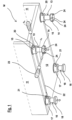
- FIG. 2 shows a regulation system not according to the invention, in which the same elements have the same reference numbers.
- plaques or connections 25 are positioned, the same for all four feet, separate and insertable in the same, i.e. two front feet 26 and two rear feet 27.
- Each front foot 26 has an upper part 28 which can be inserted in a housing 29 of the plaque 25, and a lower part 30 adjustable in height by means of rotation, as seen for the example of figure 1 with the help of a screwdriver 23.
- the upper part 28 of the front foot 26 has a pass-through hole 41 from one side to the other in its part that is inserted in the plaque 25.
- Said pass-through hole 41 is aligned with a pass-through hole 42 from one side to the other formed in the body of the plaque 25 close to the housing 29 of the foot 26 (in the example of figure 2 the left front foot of the piece of furniture).
- a further pass-through hole 43 is also provided, formed in the body of the plaque 25 at 90° with respect to the previous hole, when the same plaque 25 is assembled on an opposite edge of the furniture M for housing the opposite front right foot.
- Rear feet 27 equipped with a regulation mechanism are also provided.
- Figures 3 to 8 illustrate an example of this type of rear foot 27 which shows the relation between an upper part 44 and a lower part 45 of the rear foot 27.
- a casing in two half-shells 31, 32 be positioned in a body of the upper part 44 in an axial pass-through hole 46 (vertical in the figures), said casing containing a pinion-toothed crown bevel.
- a pinion 33 is rotatingly positioned inside a hole 34 formed in one of the two half-shells 31, which is aligned with a horizontal holing 35 of the body of the upper part 44.
- the pinion 33 engages with a toothed crown 36, formed as head of a threaded screw 37, and rotatable in a seat 38 formed in the two coupled half-shells 31 and 32.
- the threaded screw 37 is in turn positioned in a threaded axial hole 39 and inside a tubular element 40 integral with the lower part 45 of the rear supporting foot 27 on a floor.
- This lower part 45 of the foot 27 is arranged sliding and adjustable in height with respect to the upper part 44.
- the hole 35 of the body of the upper part 44 of the rear foot 27 is positioned aligned with the pass-through hole 43 provided in the plaque 25 positioned at the rear for housing the left rear foot in figure 2 .
- the rear foot 27 is housed in the housing 29 of the plaque 25 so that the hole 35 is aligned with the hole 43 of the plaque 25.
- the tip of a long-stemmed screwdriver 22 or similar tool inserted in the hole of the plaque 25 is inserted in the hole 35 of the rear foot 27 and drives the regulation mechanism of the rear foot 27 itself so as to actuate a regulation in height of the rear foot 27.
- Figure 8 is a perspective view, with some exploded feet, which illustrates a further example of a regulation system not according to the invention similar to that of figure 2 .
- This further example where the same elements have the same reference numbers, provides, as a variant, that the plaque 25 does not have pass-through or actuation holes of the regulation mechanism.
- the pass-through hole 41 passes from one side to the other in the front foot 26, in a lower area with respect to that in which it passed in the example of figure 2 . More specifically, it passes beneath an abutment flange 47 with respect to the plaque 25 which determines the correct positioning of the front foot 26 or rear foot 27 as preferred, in the respective housing 29 of the plaque 25. Said abutment flange 47 was also present in the example of figure 2 in which the pass-through hole 41 of the front foot 26 was positioned above the same and above the hole 35 of the rear foot 27.
- the regulation of the rear feet 27 is effected as for the first embodiment example shown in figure 1 with the introduction of the tip of the long-stemmed screwdriver 22 or similar tool, in the hole 41 of the front foot 26, beneath the flange 47, and with the subsequent adjustment action through the hole 35, beneath the flange 47, in the rear foot 27.
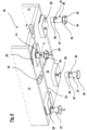
- Figure 9 is a perspective view, with some exploded feet, which illustrates a further example of a regulation system according to the invention.
- This embodiment has the same numbers for the same elements and is similar to that of figure 2 with the provision of an extension rod or transmission rod 48 for actuating the rear foot 27.
- the transmission rod 48 has an end seat 49 for a tip of a screwdriver 123 having a hexagonal tip for hexagonal seats.
- FIG. 9a is a sectional view of a detail of the system of figure 9 in correspondence with the front foot 26.
- the upper part 28 of the front foot 26 has a pass-through groove 41' in its part that is inserted in the plaque 25.
- the transmission rod 48 is blocked in said pass-through groove 41' to allow the adjustment of the rear foot 27.
- figure 2 Unlike figure 2 , in fact, it has grooves 41' as in figure 9 instead of holes 41.
- the holes 42 and 43 provided in the plaques 25 are pass-through holes from one side to the other for the passage of a tip of a long-stemmed screwdriver 22 or similar tool for the adjustment of the rear foot 27.
- the tip or stem of the screwdriver 22 therefore also passes through the grooves 41' of the front feet 26.
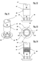
- Figures 11 to 14 show the front foot 26 provided with grooves 41' in the upper part 28 of its body.
- figures 15, 15a , 16 and 16a show embodiments of regulation systems according to the invention with rear and front feet separated from the connection or plaque 25 and both provided with a regulation mechanism. Also in this case, the same elements of the system have the same reference numbers.
- the regulation mechanism of the foot is actuated through the hole 35 underlying the groove 141'.
- the hole 35 of the rear foot 27 allows the adjustment of said foot.
- the groove 141' is therefore superimposed with respect to the actuation hole 35 of the mechanism of the foot.
- the system according to the present invention solves the problems arising from the known systems used.
- the regulation systems for the rear feet are advantageously and significantly simplified by providing a compact front regulation.
- a pass-through hole in general in the connection or even in the body of the foot provides a guide and safe and correct support for the tip of the long-stemmed screwdriver 22 or similar tool that actuates the adjustment of the rear foot. In this way, all regulation operations of the rear foot are simplified even in extremely restricted spaces.
- the adjustment of the front feet is then effected in the usual way, using a common screwdriver.
- the furniture M is provided with a pair of front feet and a pair of rear feet.
- the principles of the invention can also be applied to a piece of furniture M equipped with only one front foot and one rear foot, consequently also to a piece of furniture M equipped with at least one front foot and at least one rear foot.
- the openings of the inlet holes of the screwdriver or similar maneuvering tool are flared in order to facilitate the rapid and correct introduction of the tool itself.
- foot may be used for indicating the foot alone, or the foot and its connection to the bottom of the furniture, whether said connection be integrated (in one piece) with the foot itself, or separate from the same.
Landscapes
- Legs For Furniture In General (AREA)
Claims (5)
- Kompaktes vorderes Regulierungssystem für Nivellierfüße für Möbel (M) mit einem Boden (12) und Schultern (11), von dem Typ, die in Kombination umfasst: ein Paar von vorderen Füßen (26, 127) und ein Paar von rückwärtigen Füßen (27), wobei das Paar von rückwärtigen Füßen (27) einen Regulierungsmechanismus in der Höhe umfasst, der von außerhalb des Paars von rückwärtigen Füßen (27) zugänglich ist und mittels eines Werkzeugs (22, 48, 123) manövriert werden kann, wobei das Paar von vorderen Füßen (26, 127) ein Durchgangsloch (41', 141', 42, 43) für den Durchgang von einer Seite zur anderen eines Schafts des Regulierungswerkzeugs des Paars von rückwärtigen Füßen (27) vorsieht, wobei das Durchgangsloch als eine Stütze und Führung für den Schaft des Werkzeugs (22, 48, 123) in Richtung des Paars von rückwärtigen Füßen (27) wirkt, wobei Verbindungen (25) vorgesehen sind, die unter dem Boden (12) angebracht werden können, wobei die Verbindungen (25) die vorderen Füße (26, 127) und die rückwärtigen Füße (27), die in die Verbindungen (25) eingesetzt werden können, aufnehmen, wobei das Durchgangsloch jedes der vorderen Füße (26, 127) für das Regulierungswerkzeug (22, 48, 123) der rückwärtigen Füße (27) als ein erstes Durchgangsloch (42) in jeder der Verbindungen (25) und in der Form einer Durchgangsnut (41', 141') in jedem der vorderen Füße (26, 127) hergestellt ist, wobei jede der Verbindungen (25) ein zweites Durchgangsloch (43) vorsieht, das in dem Körper jeder Verbindung (25) unter 90° in Bezug auf das erste Durchgangsloch (42) in Übereinstimmung mit einem Rand der Verbindung (25) hergestellt ist.
- System nach Anspruch 1, dadurch gekennzeichnet, dass ein Loch (35), das mit einem Regulierungsmechanismus innerhalb des Fußes ausgerichtet ist, unter der Durchgangsnut (141') des Vorderfußes (127) hergestellt ist.
- System nach Anspruch 1, dadurch gekennzeichnet, dass der Vorderfuß (26) direkt durch Drehen eines einstellbaren unteren Teils (14) des Vorderfußes (26) reguliert wird.
- System nach einem der vorhergehenden Ansprüche, dadurch gekennzeichnet, dass der Vorderfuß (127) einen Regulierungsmechanismus innerhalb des Fußes vorsieht.
- System nach einem der vorhergehenden Ansprüche, dadurch gekennzeichnet, dass eine Rückholstange (48) in dem ersten Durchgangsloch (42) der Verbindung (25) positioniert ist.
Priority Applications (1)
| Application Number | Priority Date | Filing Date | Title |
|---|---|---|---|
| EP24166382.2A EP4364613A3 (de) | 2016-03-09 | 2017-02-27 | Kompaktes frontregelungssystem für stellfüsse für möbel |
Applications Claiming Priority (4)
| Application Number | Priority Date | Filing Date | Title |
|---|---|---|---|
| ITUA2016A001495A ITUA20161495A1 (it) | 2016-03-09 | 2016-03-09 | Sistema di regolazione frontale compatto per piedi di livellamento per mobili |
| ITUA20161495 | 2016-03-09 | ||
| EP17707315.2A EP3426093B1 (de) | 2016-03-09 | 2017-02-27 | Kompaktes frontregelungssystem für stellfüsse für möbel |
| PCT/EP2017/054439 WO2017153188A1 (en) | 2016-03-09 | 2017-02-27 | Compact front regulation system for leveling feet for furniture |
Related Parent Applications (2)
| Application Number | Title | Priority Date | Filing Date |
|---|---|---|---|
| EP17707315.2A Division EP3426093B1 (de) | 2016-03-09 | 2017-02-27 | Kompaktes frontregelungssystem für stellfüsse für möbel |
| EP17707315.2A Division-Into EP3426093B1 (de) | 2016-03-09 | 2017-02-27 | Kompaktes frontregelungssystem für stellfüsse für möbel |
Related Child Applications (2)
| Application Number | Title | Priority Date | Filing Date |
|---|---|---|---|
| EP24166382.2A Division-Into EP4364613A3 (de) | 2016-03-09 | 2017-02-27 | Kompaktes frontregelungssystem für stellfüsse für möbel |
| EP24166382.2A Division EP4364613A3 (de) | 2016-03-09 | 2017-02-27 | Kompaktes frontregelungssystem für stellfüsse für möbel |
Publications (2)
| Publication Number | Publication Date |
|---|---|
| EP3750449A1 EP3750449A1 (de) | 2020-12-16 |
| EP3750449B1 true EP3750449B1 (de) | 2024-07-24 |
Family
ID=64604400
Family Applications (2)
| Application Number | Title | Priority Date | Filing Date |
|---|---|---|---|
| EP20189775.8A Active EP3750449B1 (de) | 2016-03-09 | 2017-02-27 | Kompaktes frontregelungssystem für stellfüsse für möbel |
| EP17707315.2A Active EP3426093B1 (de) | 2016-03-09 | 2017-02-27 | Kompaktes frontregelungssystem für stellfüsse für möbel |
Family Applications After (1)
| Application Number | Title | Priority Date | Filing Date |
|---|---|---|---|
| EP17707315.2A Active EP3426093B1 (de) | 2016-03-09 | 2017-02-27 | Kompaktes frontregelungssystem für stellfüsse für möbel |
Country Status (3)
| Country | Link |
|---|---|
| EP (2) | EP3750449B1 (de) |
| ES (1) | ES2847860T3 (de) |
| PL (1) | PL3426093T3 (de) |
Family Cites Families (2)
| Publication number | Priority date | Publication date | Assignee | Title |
|---|---|---|---|---|
| EP2326232B1 (de) * | 2008-08-18 | 2016-08-10 | Arçelik Anonim Sirketi | Ein haushaltsgerät |
| AU2009227484B2 (en) * | 2008-10-17 | 2013-07-04 | Mark Romany | A levelling device and a cabinet installation including a levelling device |
-
2017
- 2017-02-27 EP EP20189775.8A patent/EP3750449B1/de active Active
- 2017-02-27 ES ES17707315T patent/ES2847860T3/es active Active
- 2017-02-27 EP EP17707315.2A patent/EP3426093B1/de active Active
- 2017-02-27 PL PL17707315T patent/PL3426093T3/pl unknown
Also Published As
| Publication number | Publication date |
|---|---|
| PL3426093T3 (pl) | 2021-05-04 |
| EP3426093B1 (de) | 2020-11-11 |
| EP3426093A1 (de) | 2019-01-16 |
| ES2847860T3 (es) | 2021-08-04 |
| EP3750449A1 (de) | 2020-12-16 |
Similar Documents
| Publication | Publication Date | Title |
|---|---|---|
| US10874214B2 (en) | Compact front regulation system for leveling feet for furniture | |
| US20190387882A1 (en) | Front adjustment system for leveling feet for furniture | |
| EP3481256B1 (de) | Verbindungssystem mit nivelliervorrichtung für möbelteile und einrichtungsgegenstände | |
| US10244867B2 (en) | Slide rail mechanism and adjusting assembly for slide rail | |
| JP2023549490A (ja) | カバーキャップの調節可能な組付け位置を有した家具用金具 | |
| EP3482086B1 (de) | Verbindungssystem mit frontbetätigungsachse für möbel | |
| EP3426093B1 (de) | Kompaktes frontregelungssystem für stellfüsse für möbel | |
| EP3025618B1 (de) | Verankerungsgruppe für wandschränke mit regelung von oben | |
| EP3328245B1 (de) | Verankerungsgruppe für wandschränke mit erhöhter kapazität mit regulierung von unten | |
| EP3328244B1 (de) | Verankerungsgruppe für wandschränke mit regulierung von unten | |
| EP3874989A1 (de) | Vereinfachtes verstellbares nivelliersystem für möbel und/oder einrichtungsgegenstände | |
| US12534946B2 (en) | Mounting device for supporting at least one door leaf | |
| EP3328246B1 (de) | Verankerungsgruppe für wandschränke mit erhöhter leistungsfähigkeit mit regelung von oben | |
| EP3349618B1 (de) | Verankerungsgruppe für wandschränke mit bereitgestellter anordnung | |
| CA3023407C (en) | Joining system with leveller for parts of furniture and furnishing items |
Legal Events
| Date | Code | Title | Description |
|---|---|---|---|
| PUAI | Public reference made under article 153(3) epc to a published international application that has entered the european phase |
Free format text: ORIGINAL CODE: 0009012 |
|
| STAA | Information on the status of an ep patent application or granted ep patent |
Free format text: STATUS: THE APPLICATION HAS BEEN PUBLISHED |
|
| AC | Divisional application: reference to earlier application |
Ref document number: 3426093 Country of ref document: EP Kind code of ref document: P |
|
| AK | Designated contracting states |
Kind code of ref document: A1 Designated state(s): AL AT BE BG CH CY CZ DE DK EE ES FI FR GB GR HR HU IE IS IT LI LT LU LV MC MK MT NL NO PL PT RO RS SE SI SK SM TR |
|
| STAA | Information on the status of an ep patent application or granted ep patent |
Free format text: STATUS: REQUEST FOR EXAMINATION WAS MADE |
|
| 17P | Request for examination filed |
Effective date: 20210607 |
|
| RBV | Designated contracting states (corrected) |
Designated state(s): AL AT BE BG CH CY CZ DE DK EE ES FI FR GB GR HR HU IE IS IT LI LT LU LV MC MK MT NL NO PL PT RO RS SE SI SK SM TR |
|
| STAA | Information on the status of an ep patent application or granted ep patent |
Free format text: STATUS: EXAMINATION IS IN PROGRESS |
|
| 17Q | First examination report despatched |
Effective date: 20221107 |
|
| GRAP | Despatch of communication of intention to grant a patent |
Free format text: ORIGINAL CODE: EPIDOSNIGR1 |
|
| STAA | Information on the status of an ep patent application or granted ep patent |
Free format text: STATUS: GRANT OF PATENT IS INTENDED |
|
| INTG | Intention to grant announced |
Effective date: 20230915 |
|
| GRAJ | Information related to disapproval of communication of intention to grant by the applicant or resumption of examination proceedings by the epo deleted |
Free format text: ORIGINAL CODE: EPIDOSDIGR1 |
|
| STAA | Information on the status of an ep patent application or granted ep patent |
Free format text: STATUS: EXAMINATION IS IN PROGRESS |
|
| INTC | Intention to grant announced (deleted) | ||
| GRAP | Despatch of communication of intention to grant a patent |
Free format text: ORIGINAL CODE: EPIDOSNIGR1 |
|
| STAA | Information on the status of an ep patent application or granted ep patent |
Free format text: STATUS: GRANT OF PATENT IS INTENDED |
|
| INTG | Intention to grant announced |
Effective date: 20240312 |
|
| GRAS | Grant fee paid |
Free format text: ORIGINAL CODE: EPIDOSNIGR3 |
|
| P01 | Opt-out of the competence of the unified patent court (upc) registered |
Effective date: 20240516 |
|
| GRAA | (expected) grant |
Free format text: ORIGINAL CODE: 0009210 |
|
| STAA | Information on the status of an ep patent application or granted ep patent |
Free format text: STATUS: THE PATENT HAS BEEN GRANTED |
|
| AC | Divisional application: reference to earlier application |
Ref document number: 3426093 Country of ref document: EP Kind code of ref document: P |
|
| AK | Designated contracting states |
Kind code of ref document: B1 Designated state(s): AL AT BE BG CH CY CZ DE DK EE ES FI FR GB GR HR HU IE IS IT LI LT LU LV MC MK MT NL NO PL PT RO RS SE SI SK SM TR |
|
| REG | Reference to a national code |
Ref country code: GB Ref legal event code: FG4D |
|
| REG | Reference to a national code |
Ref country code: CH Ref legal event code: EP |
|
| REG | Reference to a national code |
Ref country code: DE Ref legal event code: R096 Ref document number: 602017083626 Country of ref document: DE |
|
| REG | Reference to a national code |
Ref country code: IE Ref legal event code: FG4D |
|
| REG | Reference to a national code |
Ref country code: LT Ref legal event code: MG9D |
|
| REG | Reference to a national code |
Ref country code: ES Ref legal event code: FG2A Ref document number: 2988759 Country of ref document: ES Kind code of ref document: T3 Effective date: 20241121 |
|
| REG | Reference to a national code |
Ref country code: NL Ref legal event code: MP Effective date: 20240724 |
|
| PG25 | Lapsed in a contracting state [announced via postgrant information from national office to epo] |
Ref country code: PT Free format text: LAPSE BECAUSE OF FAILURE TO SUBMIT A TRANSLATION OF THE DESCRIPTION OR TO PAY THE FEE WITHIN THE PRESCRIBED TIME-LIMIT Effective date: 20241125 |
|
| REG | Reference to a national code |
Ref country code: AT Ref legal event code: UEP Ref document number: 1705440 Country of ref document: AT Kind code of ref document: T Effective date: 20240724 |
|
| PG25 | Lapsed in a contracting state [announced via postgrant information from national office to epo] |
Ref country code: NL Free format text: LAPSE BECAUSE OF FAILURE TO SUBMIT A TRANSLATION OF THE DESCRIPTION OR TO PAY THE FEE WITHIN THE PRESCRIBED TIME-LIMIT Effective date: 20240724 |
|
| PG25 | Lapsed in a contracting state [announced via postgrant information from national office to epo] |
Ref country code: PT Free format text: LAPSE BECAUSE OF FAILURE TO SUBMIT A TRANSLATION OF THE DESCRIPTION OR TO PAY THE FEE WITHIN THE PRESCRIBED TIME-LIMIT Effective date: 20241125 Ref country code: NL Free format text: LAPSE BECAUSE OF FAILURE TO SUBMIT A TRANSLATION OF THE DESCRIPTION OR TO PAY THE FEE WITHIN THE PRESCRIBED TIME-LIMIT Effective date: 20240724 |
|
| PG25 | Lapsed in a contracting state [announced via postgrant information from national office to epo] |
Ref country code: NO Free format text: LAPSE BECAUSE OF FAILURE TO SUBMIT A TRANSLATION OF THE DESCRIPTION OR TO PAY THE FEE WITHIN THE PRESCRIBED TIME-LIMIT Effective date: 20241024 |
|
| PG25 | Lapsed in a contracting state [announced via postgrant information from national office to epo] |
Ref country code: GR Free format text: LAPSE BECAUSE OF FAILURE TO SUBMIT A TRANSLATION OF THE DESCRIPTION OR TO PAY THE FEE WITHIN THE PRESCRIBED TIME-LIMIT Effective date: 20241025 Ref country code: FI Free format text: LAPSE BECAUSE OF FAILURE TO SUBMIT A TRANSLATION OF THE DESCRIPTION OR TO PAY THE FEE WITHIN THE PRESCRIBED TIME-LIMIT Effective date: 20240724 |
|
| PG25 | Lapsed in a contracting state [announced via postgrant information from national office to epo] |
Ref country code: BG Free format text: LAPSE BECAUSE OF FAILURE TO SUBMIT A TRANSLATION OF THE DESCRIPTION OR TO PAY THE FEE WITHIN THE PRESCRIBED TIME-LIMIT Effective date: 20240724 |
|
| PG25 | Lapsed in a contracting state [announced via postgrant information from national office to epo] |
Ref country code: LV Free format text: LAPSE BECAUSE OF FAILURE TO SUBMIT A TRANSLATION OF THE DESCRIPTION OR TO PAY THE FEE WITHIN THE PRESCRIBED TIME-LIMIT Effective date: 20240724 |
|
| PG25 | Lapsed in a contracting state [announced via postgrant information from national office to epo] |
Ref country code: IS Free format text: LAPSE BECAUSE OF FAILURE TO SUBMIT A TRANSLATION OF THE DESCRIPTION OR TO PAY THE FEE WITHIN THE PRESCRIBED TIME-LIMIT Effective date: 20241124 |
|
| PG25 | Lapsed in a contracting state [announced via postgrant information from national office to epo] |
Ref country code: HR Free format text: LAPSE BECAUSE OF FAILURE TO SUBMIT A TRANSLATION OF THE DESCRIPTION OR TO PAY THE FEE WITHIN THE PRESCRIBED TIME-LIMIT Effective date: 20240724 |
|
| PG25 | Lapsed in a contracting state [announced via postgrant information from national office to epo] |
Ref country code: RS Free format text: LAPSE BECAUSE OF FAILURE TO SUBMIT A TRANSLATION OF THE DESCRIPTION OR TO PAY THE FEE WITHIN THE PRESCRIBED TIME-LIMIT Effective date: 20241024 |
|
| PG25 | Lapsed in a contracting state [announced via postgrant information from national office to epo] |
Ref country code: RS Free format text: LAPSE BECAUSE OF FAILURE TO SUBMIT A TRANSLATION OF THE DESCRIPTION OR TO PAY THE FEE WITHIN THE PRESCRIBED TIME-LIMIT Effective date: 20241024 Ref country code: NO Free format text: LAPSE BECAUSE OF FAILURE TO SUBMIT A TRANSLATION OF THE DESCRIPTION OR TO PAY THE FEE WITHIN THE PRESCRIBED TIME-LIMIT Effective date: 20241024 Ref country code: LV Free format text: LAPSE BECAUSE OF FAILURE TO SUBMIT A TRANSLATION OF THE DESCRIPTION OR TO PAY THE FEE WITHIN THE PRESCRIBED TIME-LIMIT Effective date: 20240724 Ref country code: IS Free format text: LAPSE BECAUSE OF FAILURE TO SUBMIT A TRANSLATION OF THE DESCRIPTION OR TO PAY THE FEE WITHIN THE PRESCRIBED TIME-LIMIT Effective date: 20241124 Ref country code: HR Free format text: LAPSE BECAUSE OF FAILURE TO SUBMIT A TRANSLATION OF THE DESCRIPTION OR TO PAY THE FEE WITHIN THE PRESCRIBED TIME-LIMIT Effective date: 20240724 Ref country code: GR Free format text: LAPSE BECAUSE OF FAILURE TO SUBMIT A TRANSLATION OF THE DESCRIPTION OR TO PAY THE FEE WITHIN THE PRESCRIBED TIME-LIMIT Effective date: 20241025 Ref country code: FI Free format text: LAPSE BECAUSE OF FAILURE TO SUBMIT A TRANSLATION OF THE DESCRIPTION OR TO PAY THE FEE WITHIN THE PRESCRIBED TIME-LIMIT Effective date: 20240724 Ref country code: BG Free format text: LAPSE BECAUSE OF FAILURE TO SUBMIT A TRANSLATION OF THE DESCRIPTION OR TO PAY THE FEE WITHIN THE PRESCRIBED TIME-LIMIT Effective date: 20240724 |
|
| PG25 | Lapsed in a contracting state [announced via postgrant information from national office to epo] |
Ref country code: DK Free format text: LAPSE BECAUSE OF FAILURE TO SUBMIT A TRANSLATION OF THE DESCRIPTION OR TO PAY THE FEE WITHIN THE PRESCRIBED TIME-LIMIT Effective date: 20240724 Ref country code: RO Free format text: LAPSE BECAUSE OF FAILURE TO SUBMIT A TRANSLATION OF THE DESCRIPTION OR TO PAY THE FEE WITHIN THE PRESCRIBED TIME-LIMIT Effective date: 20240724 Ref country code: SM Free format text: LAPSE BECAUSE OF FAILURE TO SUBMIT A TRANSLATION OF THE DESCRIPTION OR TO PAY THE FEE WITHIN THE PRESCRIBED TIME-LIMIT Effective date: 20240724 |
|
| PG25 | Lapsed in a contracting state [announced via postgrant information from national office to epo] |
Ref country code: EE Free format text: LAPSE BECAUSE OF FAILURE TO SUBMIT A TRANSLATION OF THE DESCRIPTION OR TO PAY THE FEE WITHIN THE PRESCRIBED TIME-LIMIT Effective date: 20240724 |
|
| PG25 | Lapsed in a contracting state [announced via postgrant information from national office to epo] |
Ref country code: CZ Free format text: LAPSE BECAUSE OF FAILURE TO SUBMIT A TRANSLATION OF THE DESCRIPTION OR TO PAY THE FEE WITHIN THE PRESCRIBED TIME-LIMIT Effective date: 20240724 |
|
| REG | Reference to a national code |
Ref country code: DE Ref legal event code: R097 Ref document number: 602017083626 Country of ref document: DE |
|
| PG25 | Lapsed in a contracting state [announced via postgrant information from national office to epo] |
Ref country code: SK Free format text: LAPSE BECAUSE OF FAILURE TO SUBMIT A TRANSLATION OF THE DESCRIPTION OR TO PAY THE FEE WITHIN THE PRESCRIBED TIME-LIMIT Effective date: 20240724 |
|
| PLBE | No opposition filed within time limit |
Free format text: ORIGINAL CODE: 0009261 |
|
| STAA | Information on the status of an ep patent application or granted ep patent |
Free format text: STATUS: NO OPPOSITION FILED WITHIN TIME LIMIT |
|
| 26N | No opposition filed |
Effective date: 20250425 |
|
| PG25 | Lapsed in a contracting state [announced via postgrant information from national office to epo] |
Ref country code: SE Free format text: LAPSE BECAUSE OF FAILURE TO SUBMIT A TRANSLATION OF THE DESCRIPTION OR TO PAY THE FEE WITHIN THE PRESCRIBED TIME-LIMIT Effective date: 20240724 |
|
| PG25 | Lapsed in a contracting state [announced via postgrant information from national office to epo] |
Ref country code: MC Free format text: LAPSE BECAUSE OF FAILURE TO SUBMIT A TRANSLATION OF THE DESCRIPTION OR TO PAY THE FEE WITHIN THE PRESCRIBED TIME-LIMIT Effective date: 20240724 |
|
| REG | Reference to a national code |
Ref country code: CH Ref legal event code: PL |
|
| PG25 | Lapsed in a contracting state [announced via postgrant information from national office to epo] |
Ref country code: LU Free format text: LAPSE BECAUSE OF NON-PAYMENT OF DUE FEES Effective date: 20250227 |
|
| PG25 | Lapsed in a contracting state [announced via postgrant information from national office to epo] |
Ref country code: CH Free format text: LAPSE BECAUSE OF NON-PAYMENT OF DUE FEES Effective date: 20250228 |
|
| GBPC | Gb: european patent ceased through non-payment of renewal fee |
Effective date: 20250227 |
|
| REG | Reference to a national code |
Ref country code: BE Ref legal event code: MM Effective date: 20250228 |
|
| PG25 | Lapsed in a contracting state [announced via postgrant information from national office to epo] |
Ref country code: GB Free format text: LAPSE BECAUSE OF NON-PAYMENT OF DUE FEES Effective date: 20250227 |
|
| PG25 | Lapsed in a contracting state [announced via postgrant information from national office to epo] |
Ref country code: BE Free format text: LAPSE BECAUSE OF NON-PAYMENT OF DUE FEES Effective date: 20250228 |
|
| PG25 | Lapsed in a contracting state [announced via postgrant information from national office to epo] |
Ref country code: IE Free format text: LAPSE BECAUSE OF NON-PAYMENT OF DUE FEES Effective date: 20250227 |
|
| PGFP | Annual fee paid to national office [announced via postgrant information from national office to epo] |
Ref country code: ES Payment date: 20260302 Year of fee payment: 10 |
|
| PGFP | Annual fee paid to national office [announced via postgrant information from national office to epo] |
Ref country code: DE Payment date: 20260227 Year of fee payment: 10 |
|
| PGFP | Annual fee paid to national office [announced via postgrant information from national office to epo] |
Ref country code: AT Payment date: 20260227 Year of fee payment: 10 |
|
| PGFP | Annual fee paid to national office [announced via postgrant information from national office to epo] |
Ref country code: IT Payment date: 20260217 Year of fee payment: 10 |
|
| PGFP | Annual fee paid to national office [announced via postgrant information from national office to epo] |
Ref country code: FR Payment date: 20260225 Year of fee payment: 10 |
|
| PGFP | Annual fee paid to national office [announced via postgrant information from national office to epo] |
Ref country code: PL Payment date: 20260206 Year of fee payment: 10 |