EP3148374B1 - Stützrahmen für ein möbelstück - Google Patents
Stützrahmen für ein möbelstück Download PDFInfo
- Publication number
- EP3148374B1 EP3148374B1 EP15733617.3A EP15733617A EP3148374B1 EP 3148374 B1 EP3148374 B1 EP 3148374B1 EP 15733617 A EP15733617 A EP 15733617A EP 3148374 B1 EP3148374 B1 EP 3148374B1
- Authority
- EP
- European Patent Office
- Prior art keywords
- base unit
- lifting column
- housing
- supporting frame
- cross member
- Prior art date
- Legal status (The legal status is an assumption and is not a legal conclusion. Google has not performed a legal analysis and makes no representation as to the accuracy of the status listed.)
- Active
Links
Images




Classifications
-
- A—HUMAN NECESSITIES
- A47—FURNITURE; DOMESTIC ARTICLES OR APPLIANCES; COFFEE MILLS; SPICE MILLS; SUCTION CLEANERS IN GENERAL
- A47B—TABLES; DESKS; OFFICE FURNITURE; CABINETS; DRAWERS; GENERAL DETAILS OF FURNITURE
- A47B13/00—Details of tables or desks
- A47B13/02—Underframes
- A47B13/021—Fastening devices of the feet or legs
-
- F—MECHANICAL ENGINEERING; LIGHTING; HEATING; WEAPONS; BLASTING
- F16—ENGINEERING ELEMENTS AND UNITS; GENERAL MEASURES FOR PRODUCING AND MAINTAINING EFFECTIVE FUNCTIONING OF MACHINES OR INSTALLATIONS; THERMAL INSULATION IN GENERAL
- F16B—DEVICES FOR FASTENING OR SECURING CONSTRUCTIONAL ELEMENTS OR MACHINE PARTS TOGETHER, e.g. NAILS, BOLTS, CIRCLIPS, CLAMPS, CLIPS OR WEDGES; JOINTS OR JOINTING
- F16B12/00—Jointing of furniture or the like, e.g. hidden from exterior
- F16B12/44—Leg joints; Corner joints
-
- F—MECHANICAL ENGINEERING; LIGHTING; HEATING; WEAPONS; BLASTING
- F16—ENGINEERING ELEMENTS AND UNITS; GENERAL MEASURES FOR PRODUCING AND MAINTAINING EFFECTIVE FUNCTIONING OF MACHINES OR INSTALLATIONS; THERMAL INSULATION IN GENERAL
- F16B—DEVICES FOR FASTENING OR SECURING CONSTRUCTIONAL ELEMENTS OR MACHINE PARTS TOGETHER, e.g. NAILS, BOLTS, CIRCLIPS, CLAMPS, CLIPS OR WEDGES; JOINTS OR JOINTING
- F16B12/00—Jointing of furniture or the like, e.g. hidden from exterior
- F16B12/44—Leg joints; Corner joints
- F16B12/52—Metal leg connections
-
- A—HUMAN NECESSITIES
- A47—FURNITURE; DOMESTIC ARTICLES OR APPLIANCES; COFFEE MILLS; SPICE MILLS; SUCTION CLEANERS IN GENERAL
- A47B—TABLES; DESKS; OFFICE FURNITURE; CABINETS; DRAWERS; GENERAL DETAILS OF FURNITURE
- A47B13/00—Details of tables or desks
- A47B13/02—Underframes
- A47B13/021—Fastening devices of the feet or legs
- A47B2013/022—Fastening devices of the feet or legs with detachable connection of a tubular leg
-
- A—HUMAN NECESSITIES
- A47—FURNITURE; DOMESTIC ARTICLES OR APPLIANCES; COFFEE MILLS; SPICE MILLS; SUCTION CLEANERS IN GENERAL
- A47B—TABLES; DESKS; OFFICE FURNITURE; CABINETS; DRAWERS; GENERAL DETAILS OF FURNITURE
- A47B2200/00—General construction of tables or desks
- A47B2200/0011—Underframes
- A47B2200/0014—Dismountable central or lateral longitudinal members linking two pairs of legs to frame
-
- A—HUMAN NECESSITIES
- A47—FURNITURE; DOMESTIC ARTICLES OR APPLIANCES; COFFEE MILLS; SPICE MILLS; SUCTION CLEANERS IN GENERAL
- A47B—TABLES; DESKS; OFFICE FURNITURE; CABINETS; DRAWERS; GENERAL DETAILS OF FURNITURE
- A47B9/00—Tables with tops of variable height
- A47B9/20—Telescopic guides
Definitions
- the present invention relates to a supporting frame for a piece of furniture with a lifting column comprising at least one profile having an upper and lower end, said upper end having a housing secured thereto.
- Lifting columns comprising a telescopic guide and a box-shaped housing for height-adjustable tables were developed in the late 1990s, where the telescopic guide has the appearance of a table leg.
- the box-shaped housing usually rectangular, contains an electric motor, transmission and various electronics.
- An example of such a lifting column is shown in Fig. 1 of WO 2004/100632 A1 to LINAK A/S .
- a different type of lifting column is described in WO 03/003876 A1 to LINAK A/S , where the entire drive unit, i.e. electric motor, transmission and various electronics, is integrated in the telescopic guide.
- a supporting frame comprising an upper frame, which typically comprises two longitudinal members and two cross members, at least one lifting column and at least one foot.
- the lifting column can, as described above, be constructed with or without a box-shaped housing at the upper end.
- the longitudinal members are usually constructed as throughgoing tubular profiles placed in parallel having a mutual distance between them corresponding to the width of the box-shaped housing.
- To each end of the longitudinal members a cross member is secured.
- the longitudinal members and the cross members are usually welded up or should be assembled by means of screws.
- a lifting column is mounted at each end in that the box-shaped housing is positioned between the longitudinal members with one end up against the respective cross member. The lifting column is secured by means of screws through the two longitudinal members and the cross member into the box-shaped housing.
- the purpose of the invention is to provide a supporting frame comprising electrically driven lifting columns for an adjustable piece of furniture, which in a simple and non-time-consuming manner can be assembled and secured to the desired piece of furniture.
- the supporting frame with a base unit having a compartment at least for partial reception of the housing of the lifting column, and a cross member for mounting on the base unit.
- the supporting frame comprises a locking element, which when placed in a locked position exerts a squeezing force between the base unit, the housing of the lifting column and the cross member, by which the lifting column housing and the cross member are fixed in the base unit.
- the supporting frame further comprises means for retaining the locking element in the locked position.
- the lifting columns are of the type comprising telescopically arranged profiles with an upper and lower end, to which upper end a housing is secured.
- the base unit has a U-shaped cross section with two parallel side walls having a mutual distance between them corresponding to the width of the lifting column housing and where the guide for the base unit is placed on the parallel side walls.
- a supporting frame is achieved, which is simple and easy to assemble and mount without the use of tools.
- screw operations are eliminated.
- the cross member has a profile with a C-shaped cross section prepared for engagement with the base unit.
- the base unit comprises flaps for engagement with the cross member. Thus, the base unit can be received in the cross member.
- the base unit comprises a guide, which depending on the construction of the supporting frame functions as a guide for correct mounting of the lifting column, including fixation of this in the base unit.
- the guide of the base unit is placed on or constructed in the side walls of the base unit.
- the base unit comprises a transverse wall, which connects the two parallel side walls of the base unit, against said transverse wall a rear end of the lifting column housing can rest.
- the fixation is improved in that yet another surface of the housing is fixed to the base unit.
- the transverse wall comprises a tongue, which with an end protrudes into the compartment of the base unit, i.e. the compartment which at least partially receives the housing of the lifting column.
- the cross member comprises a tongue which, when the cross member is mounted to the base unit, with an end protrudes into the compartment of the base unit, i.e. the compartment which at least partially receives the housing of the lifting column.
- the lifting column housing comprises an indentation for engagement with the tongue in the transverse wall or the cross member.
- the base unit comprises a flap placed such that it is in continuation of the side walls of the base unit.
- the supporting frame comprises a clamp with guides for cooperation with the guide on the base unit.
- the housing of the lifting column is placed between the base unit and the clamp.
- the locking element When the locking element is placed in the locked position, this will in cooperation with the base unit and the clamp exert a squeezing force on the lifting column housing, which propagates to the cross member.
- the housing of the lifting column and the cross member is fixed to the base unit.
- the locking element can in an embodiment be inserted and retained in the locked position in an opening in the clamp.
- the cross section of the base unit is in the shape of a hollow profile in which the lifting column housing can be arranged by sliding it in from an open end.
- the hollow profile of the base unit comprises a recess for the telescopically arranged profiles of the lifting column, by which the entire housing of the lifting column can be received in the base unit.
- the hollow profile of the base unit can comprise an opening in which the locking element is inserted and retained in a locked position.
- the housing of the lifting column comprises a guide for cooperation with the guide on the base unit.
- the lifting column and the cross member can be fixed to the base unit without using a clamp.
- the base unit comprises an opening in which the locking element can be inserted and retained in the locked position.
- the lifting column is of the type, where an electric motor and a transmission for bringing about the movement of the lifting column are arranged in the housing of the lifting column.
- the supporting frame is of the type where an electric motor and a transmission for bringing about the movement of the lifting column are arranged in one of the telescopically arranged profiles and where the housing as a separate unit is mounted on a free end of one of the outermost telescopically arranged profiles.
- the housing thus functions as an adaptor by which it is possible to use this type of lifting column for the supporting frame.
- the height-adjustable table 1 shown in Fig. 1 comprises a table top 2 having a front side 3 at which a user is expected to be situated, a rear side 4, a right side 5 and a left side 6. At the right side 5 and left side 6, respectively, of the table top 2 there is a telescopic lifting column 7.
- the lower end of the lifting columns 7 is mounted with an elongated foot 8, which extends in a direction across the table.
- the telescopic lifting columns 7 can be adjusted in their longitudinal direction by means of an operating unit 9, by which the height of the table top 2 can be adjusted.
- the two lifting columns 7 are connected to a control box comprising a controller. Further, the control box is connected to the operating unit 9 from which the height of the table top 2 can be adjusted.
- Fig. 2 shows a first embodiment of a supporting frame for the height-adjustable table shown in Fig. 1 .
- the supporting frame further comprises two base units 10,11 and two clamps 12,13 between which the lifting columns are mounted.
- the two base units 10,11 are connected to the two telescopically arranged longitudinal members 14,15. Further, each of the base units has a cross member 16,17 secured thereto.
- Figs. 3 and 4 illustrate a lifting column 18 shown in a perspective view and from the side, respectively.
- Fig. 5 shows the same lifting column 18 in a partially extended position.
- the lifting column comprises a guide consisting of three telescopically arranged rectangular profiles 19,20,21.
- the lifting column 18 comprises a box-shaped housing 22.
- a linear actuator see Fig. 6 .
- the linear actuator consists of a motor unit 23 arranged in the box-shaped housing 22 (see Fig. 6 ) and a linear moveable activation element arranged in the hollow of the rectangular profiles 19,20,21.
- the motor unit 23 comprises a reversible electric motor 25 and a transmission 26.
- the linear moveable activation element is constructed as a spindle unit connected to the transmission 26 of the motor unit through a hole in the bottom portion 27 of the motor housing.
- the spindle unit consists of a solid spindle 28, a hollow spindle 29 and a tube 30 with a spindle nut at the top.
- the housing 22 consists of a rectangular steel box having two parallel side portions 31,32, a front end 33 and a rear end 34, which are parallel, as well as a bottom portion 27.
- the top of the housing 22 can be closed by means of a cover 35.
- the external surfaces on the front end 33 and the two side portions 31,32 comprise two surfaces.
- a first plane surface 31a,33a see Fig.
- Fig. 7 shows a perspective view of a different type of lifting column 35 without housing, a so-called in-line lifting column, where the entire drive unit, including electric motor 37 and transmission 38, is arranged in the telescopically arranged profiles 39,40,41.
- Fig. 8 shows a housing 42 as a separate unit intended for mounting at the topmost end of the lifting column 35, more precisely for mounting in the profile 41.
- the housing 42 consists of a rectangular steel box with two parallel side portions 43,44, a front end 45 and a rear end 46, which are parallel, as well as a bottom portion 47.
- the top of the housing 42 can be closed by means of a cover.
- the housing comprises a mounting surface 48 for mounting of a lifting column 35 of the type shown in Fig. 7 .
- the rear end further comprises two indentations 58a,58b.
- Fig 9 shows a perspective view of the lifting column 35 mounted with the housing 42.
- the drive unit in Fig. 10 is constructed as a linear actuator for bringing about the telescopic movement of the lifting column 35.
- the linear actuator comprises a spindle unit consisting of a solid spindle 49 and a hollow spindle 50, both with external threads.
- a spindle nut 51 for the solid spindle 49 is secured, said spindle nut 51 is constructed as a bushing with internal threads.
- the hollow spindle 50 is surrounded by a drive tube 53, which on the internal side is equipped with a number of axially running grooves 54.
- the external side is fitted with a ring 55 having a number of external fins protruding into the grooves 54 on the drive tube 53.
- a guide tube 56 Surrounding the drive tube 53 there is a guide tube 56 at the lower end of which, a spindle nut 57 for the hollow spindle 50 is secured.
- the spindle nut 57 is in the shape of a bushing with internal threads.
- the drive tube 53 is driven by an electric motor 37 through a transmission 38.
- the transmission comprises a worm gear, which through a gear wheel set drives a crown wheel, which then drives the drive tube 53.
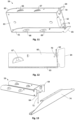
- Fig. 11 shows in a second embodiment of the supporting frame, a perspective view of a base unit 59 with two side walls 60,61, a transverse wall 62 between the two side walls 60,61 and a bottom 63.
- the side walls 60,61 are at the transverse wall 62 extended by two flaps 64,65 with two recesses located opposite each other, such that the flaps appear as double-sided hooks or clasps.
- Each side wall 60,61 comprises two guides 66,67;68,69 functioning as guiding.
- the transverse wall 62 of the base unit has two tongues 70,71, which with their free ends face into and extend towards the bottom 63 of the base unit.
- Fig. 12 shows the base 59 in a longitudinal section parallel to the side walls 60,61.
- Figs. 13-26 the first embodiment of the supporting frame is described in the following, including how to assemble it.
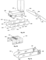
- the arrows 72,73 in Figs. 13 and 14 respectively, show how the flaps 64,65 of the base unit are guided into the C-shaped profile of the cross member 74.
- Fig. 15 shows, seen from the side wall 61 of the base unit 59, how the flap 65 is received in the profile of the cross member 74.
- Fig. 16 shows a perspective view of the placement of the base unit 59 in the cross member 74. It is noted that both the base unit 59 as well as the cross member 54 comprises a number of mounting holes 75,76;77,78 for mounting of a table top to the supporting frame.
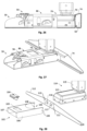
- Figs. 17 to 21 show a perspective view and section of how the lifting column 79, and more specifically, how the lifting column housing 80, is placed in the base unit 59. Due to the clarity of the figures the telescopically arranged profiles 81 have been shown cut off. The placement of the lifting column housing 80 in the base unit 59 is indicated by the arrows 82,83, which thus show that the lifting column housing 80 is arranged against the bottom 63 of the base unit and between the side walls 60,61 of the base unit.
- the lifting column 79 is positioned such that the rear end 84 (corresponding to the rear end 43,54 in Figs. 3 and 8 , respectively) of the lifting column housing 80 engages the transverse wall 62.
- the rear end 84 has two indentations 85 (only one has been numbered) corresponding to the indentations 24a,24b;58a,58b in Figs. 3 and 8 , respectively.
- the tongue 70 in the transverse wall 62 of the base unit is in engagement with the indentation 85 on the lifting column housing 80.
- Figs. 22 and 23 show how the clamp 86 is mounted on the base unit 59.
- the clamp 86 which has a U-shaped cross section, is furnished with two holes 89,90;91,92 on each side wall 87,88.
- the holes 89,90;91,92 of the clamp are in engagement with the guide 66,67;68,69 of the base unit, by which the clamp 86 can be guided along the base unit 59.
- the clamp 86 has an opening 93 in which a locking element in the shape of a locking block 94 can be inserted, see Fig. 24 .
- the locking block 94 can in a rotatable manner be pressed into the opening to a locked position, see Fig. 26 .
- the surface 95 of the locking block will during this movement engage the front end 96 of the lifting column housing 80.
- a displacement between the lifting column housing 80 and the clamp 86 relative to the base unit 59 occurs.
- the clamp 86 is pushed in a direction away from the transverse wall 62 of the base unit and towards the bottom 63 of the base unit. Further, the lifting column housing 80 is pushed against the transverse wall 62 of the base unit.
- the tongue 70 exerts a downwardly directed force against the bottom of the indentation 85.
- the tongue 70 is pushed backwards toward the transverse wall 62 it rotates about its point of attachment and thereby extends further downwards.
- the lifting column housing 80 is pushed further down towards the bottom 63 of the base unit, see arrow 100 in Fig. 21 .
- the transverse wall is pushed against the cross member 94, see arrow 101 in Fig. 21 .
- the lifting column 79 and the transverse wall 74 are positioned and fixed to the base unit.
- Fig. 27 shows how the supporting frame according to the first embodiment appears assembled.
- Fig. 28 shows an exploded perspective view of an embodiment of the supporting frame not according to the invention.
- the base unit 102 is designed with a cross section as a rectangular hollow profile.
- the base unit 102 comprises an opening 103 adapted for the locking element 104.
- the base unit 102 further comprises a recess 105, which is open towards one end of the base unit 102.
- the side walls 106,107 have a number of hook- or clasp-shaped flaps 108,109 which are prepared for engagement with a corresponding number of holes 110,111 in a cross member 112.
- the housing 113 For assembly of the supporting frame the housing 113 is placed on the lifting column 114 in the base part 102 in such a manner that the telescopically arranged profiles 115 of the lifting column extend from the recess 105 in the base unit 102. Subsequently, the cross member 112 is secured to the base unit 102 through engagement between the flaps 108,109 and the recesses 110,111. Finally, the locking element 104 is inserted into the opening 103 and pressed into a locked position. Thus, the lifting column housing 113 is pushed against the cross member 112.
- the lifting column housing 113 is pushed down towards the bottom of the hollow profile of the base unit.
- the lifting column 114 and the cross member 112 are fixed to the base unit 102 and the supporting frame appears assembled.
- Fig. 29 shows a third embodiment of the supporting frame in exploded perspective view and seen from the end of the telescopically arranged profiles of the lifting column and towards the lifting column housing, respectively.
- the base unit 118 has a U-shaped cross section and the side walls 119,120 each comprises two guides 121,122;123,124.
- the side walls 127,128 of the housing 126 likewise comprises guides 129,130. It is noted that only the guides 129,130 on the side wall 127 are shown. Corresponding guides are located at the opposite side wall 128.
- the guides 129,130 on the side wall 127 are intended for engagement with the guides 123,124 on the side wall 120 of the base unit 118.
- Each of the side walls 119,120 comprises an opening 131,132 in which a locking element in the shape of a locking block 133,134 can be inserted and fastened.
- the base unit 118 comprises hook- or clasp-shaped flaps 135,136 prepared for engagement with the holes 137,138 on the cross member 139 which thus can be mounted to the base unit 118.
- the guides 129,130 on the side wall 127 enters into engagement with the cooperating guides 123,124 on the side wall 120 of the base unit 118.
- the locking blocks 133, 134 are subsequently inserted into openings 131,132, and can in a rotatable manner be pressed down into the openings 131,132 to a locked position.
- the lifting column housing 126 is pushed against the cross member 139.
- Figs. 30 and 31 show alternative embodiments of a clamp 143 and a base unit 144, respectively.
- the clamp 143 is constructed with two reinforcements 145 on the outer side of the bottom 146 of the U-shaped profile of the clamp 143.
- the base unit 144 is constructed with reinforcements 147, 148 on each of the side walls 149,150 of the base unit 144.
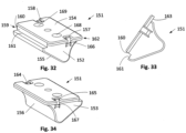
- the construction and functions of the locking block, as described above, are described in the following with reference to Figs. 32-34 , where the locking block is referenced 151.
- the locking block 151 is in all essentials wedge-shaped with two sides 152,153, a top surface 154, a first end surface, a rear surface 155 and a second end surface, front surface 156.
- the top surface 154 comprises a recess 157,158 at each of the two sides 152,153.
- the locking block comprises a projecting edge 159.
- the projecting edge 159 comprises a vertical surface 160 for engagement with a side surface in the opening in which the locking block is to be fixed.
- the projecting edge 159 further comprises a horizontal surface 161 for engagement against the underside of the unit (clamp or base unit) in which the locking block 151 is fixed.
- the top surface 154 extends with a collar 162 over the two sides 152,153 and the front surface 156.
- the underside 163 of the collar 162 is intended for engagement against the upper side of the unit (clamp or base unit) in which the locking block is fixed.
- the transition from the underside 163 of the collar 162 to the two sides 152,153 of the locking block and the front surface 156 is approximately perpendicular to the top surface 154. After the transition the front surface 156 has a concave course, after which it runs convex in the transition to the rear surface 155. From this transition the rear surface 155 has a straight course, which finally is rounded off in the transition to the projecting edge 159.
- Each of the two recesses 157,158 in the sides 152,153 is furnished with a snap lock, constructed as flaps 164,165 which in a resting position extend in a direction perpendicular to the top surface 154.
- the flaps 164,165 are secured to the bottom of the recesses 157,158, which partially enclose the flaps 164,165.
- the free space between the recesses 164,165 and the flaps 164,165 enables the flaps 164,165 to tilt in a direction perpendicular to the two sides 152,153 of the locking block.
- Each of the flaps 164,165 of the snap lock comprises a collar with a projecting edge 166,167, which has a surface parallel to the top surface 154, prepared for engagement against the underside of the unit (clamp or base unit) in which the locking block is fixed.
- the locking block 151 For bringing the locking block 151 into a locked position the locking block 151 is inserted into an opening in a clamp or a base unit such that the projecting edge 159 is in engagement with a rear edge in the opening. Further, the concave transition from the front surface 156 to the rear surface 155 of the locking block 151 rests on the front end of the lifting column housing. By applying a force on the top surface 154 the locking block 151 is in a rotatable manner pressed into the opening; it rotates around the rear edge in the opening. Further, the lifting column housing is pushed in a direction away from the locking block 151, as the contact between the front surface 156 of the locking block and the front end of the lifting column housing gradually changes from a line of action to a plane of action.
- the flaps 164,165 of the snap locks are tilted backwards in a direction towards each other and returns to their resting position when the projecting edges 166,167 engages the underside of the unit (clamp or base unit) in which the locking block is fixed.
- the locking block 151 is thus wedged in the unit as a result of: the engagement between the horizontal surface 161 of the projecting edge 159 and the underside of the unit, the engagement in the plane of action between the front surface 156 of the locking block and the front end of the lifting column housing, and the engagement between the projecting edges 166,167 and the underside of the unit.
- the locking block 151 is in its locked position.
- the locking block 164 can be brought out of its locked position by tilting the flaps 164,165 of the snap lock backwards in a direction against each other and bring the front surface 156 of the locking block out of engagement with the front end of the lifting column housing.
- the latter is expediently done by inserting a screw driver or the like into one of the holes 168,169 in the top surface 154.
- the invention is here particularly mentioned in connection with height-adjustable tables, but it is under understood that the invention can also be used in connection with other types of furniture. It is further noted that even though the invention initially is intended for mounting of electrically driven lifting columns it is obvious that the invention can also be used for mounting of manually adjustable lifting columns as long as there is a housing at the upper end thereof.
Landscapes
- Engineering & Computer Science (AREA)
- General Engineering & Computer Science (AREA)
- Mechanical Engineering (AREA)
- Tables And Desks Characterized By Structural Shape (AREA)
- Legs For Furniture In General (AREA)
- Furniture Connections (AREA)
- Curtains And Furnishings For Windows Or Doors (AREA)
Claims (9)
- Tragrahmen, umfassendeine Hubsäule (7,14,26,79,114,125) mit teleskopisch angeordneten Profilen (15,16,17;27,28,29), wobei die teleskopisch angeordneten Profile (15,16,17;27,28,29) ein oberes und ein unteres Ende aufweisen und an dem oberen Ende ein Gehäuse (18,30,80,113,126) befestigt ist,eine Basiseinheit (10,59,102,118), die ein Fach mindestens zur teilweisen Aufnahme des Hubsäulengehäuses (18,30,80,113,126) umfasst,eine Traverse (13,74,112,139) zum Montieren der Basiseinheit (10,59,102,118),ein Verriegelungselement (94,104,133,134), das, wenn es in einer verriegelten Position platziert ist, eine Quetschkraft zwischen der Basiseinheit (10,59,102,118), dem Hubsäulengehäuse (18,30,80,113,126) und der Traverse (13,74,112,139) ausübt, wodurch das Hubsäulengehäuse (18,30,80,113,126) und die Traverse (13,74,112,139) in der Basiseinheit (10,59,102,118) fixiert sind und wobei das Verriegelungselement (94,104,133,134) Mittel zum Halten des Verriegelungselements (94,104,133,134) in der verriegelten Position umfasst,gekennzeichnet dadurch, dass die Basiseinheit (10,59,118) einen U-förmigen Querschnitt mit zwei parallelen Seitenwänden (60,61;119,120) aufweist, die einen Abstand zueinander aufweisen, welcher der Breite des Hubsäulengehäuses (80, 126) entspricht.
- Tragrahmen nach Anspruch 1, gekennzeichnet dadurch, dass die Traverse (13,74,112,139) einen C-förmigen Querschnitt aufweist, der für einen Eingriff in die Basiseinheit (10,59,102,118) vorgesehen ist.
- Tragrahmen nach Anspruch 2, gekennzeichnet dadurch, dass die Basiseinheit (10,59,102,118) Klappen (64,65;108,109;135,136) für einen Eingriff in die Traverse (13,74,112,139) umfasst.
- Tragrahmen nach Anspruch 1, gekennzeichnet dadurch, dass die Basiseinheit (10,59) eine Querwand (62) zwischen den Seitenwänden (60,61) der Basiseinheit umfasst.
- Tragrahmen nach Anspruch 4, gekennzeichnet dadurch, dass die Querwand (62) eine Lasche (70,71) umfasst, die mit einem Ende in das Fach in der Basiseinheit ragt, das zur mindestens teilweisen Aufnahme des Hubsäulengehäuses (80) vorgesehen ist.
- Tragrahmen nach Anspruch 1, gekennzeichnet dadurch, dass die Traverse (13,74,112,139) eine Lasche (116,117,140,141) umfasst, die, wenn die Traverse (112,139) an der Basiseinheit (102,118) montiert ist, zur mindestens teilweisen Aufnahme des Hubsäulengehäuses (113,126) mit einem freien Ende in das Fach der Basiseinheit ragt.
- Tragrahmen nach Anspruch 5 oder 6, gekennzeichnet dadurch, dass das Gehäuse (18,30,80,113,126) der Hubsäule eine Vertiefung (24a,24b;58a,58b;85) zum Eingriff mit der Lasche (70,71,116,117,140,141) in die Querwand (62) oder die Traverse (112,139) umfasst.
- Tragrahmen nach Anspruch 3, gekennzeichnet dadurch, dass die Klappe (64,65,108,109,135,136) eine Verlängerung des Fachs der Basiseinheit ist.
- Höhenverstellbarer Tisch, umfassend einen Tragrahmen nach einem oder mehreren der Ansprüche 1-8.
Applications Claiming Priority (3)
| Application Number | Priority Date | Filing Date | Title |
|---|---|---|---|
| DKPA201400284 | 2014-05-26 | ||
| DKPA201500176 | 2015-03-20 | ||
| PCT/DK2015/000022 WO2015180725A1 (en) | 2014-05-26 | 2015-05-26 | Supporting frame for a piece of furniture |
Publications (2)
| Publication Number | Publication Date |
|---|---|
| EP3148374A1 EP3148374A1 (de) | 2017-04-05 |
| EP3148374B1 true EP3148374B1 (de) | 2024-11-06 |
Family
ID=53502389
Family Applications (1)
| Application Number | Title | Priority Date | Filing Date |
|---|---|---|---|
| EP15733617.3A Active EP3148374B1 (de) | 2014-05-26 | 2015-05-26 | Stützrahmen für ein möbelstück |
Country Status (5)
| Country | Link |
|---|---|
| US (1) | US10004326B2 (de) |
| EP (1) | EP3148374B1 (de) |
| JP (1) | JP6647219B2 (de) |
| CN (1) | CN106460903B (de) |
| WO (1) | WO2015180725A1 (de) |
Families Citing this family (21)
| Publication number | Priority date | Publication date | Assignee | Title |
|---|---|---|---|---|
| JP6647219B2 (ja) * | 2014-05-26 | 2020-02-14 | リナック エー/エス | 家具用支持フレーム |
| DK3148372T3 (da) * | 2014-05-26 | 2021-07-19 | Linak As | Bærende ramme for et møbel |
| US11096481B2 (en) * | 2017-07-28 | 2021-08-24 | Varidesk, Llc | Motorized adjustable height table |
| DE102017127937A1 (de) * | 2017-11-27 | 2019-05-29 | Logicdata Electronic & Software Entwicklungs Gmbh | Teleskopierbarer Linearaktuator und höhenverstellbarer Tisch |
| TWI648021B (zh) * | 2017-12-12 | 2019-01-21 | 林于真 | 桌子升降裝置 |
| CN209171562U (zh) * | 2017-12-25 | 2019-07-30 | 江阴市高奕机械工业有限公司 | 单柱洽谈桌 |
| EP3764841B1 (de) * | 2018-03-14 | 2024-12-25 | Linak A/S | Gestell für einen tisch |
| US10729233B2 (en) * | 2018-05-24 | 2020-08-04 | OMT-Veyhl USA Corporation | Length adjustable support and components of same |
| CN108783887B (zh) * | 2018-06-22 | 2023-11-21 | 浙江捷昌线性驱动科技股份有限公司 | 一种快速安装的桌架和升降平台 |
| US10758036B2 (en) * | 2018-09-19 | 2020-09-01 | Dong Guan Song Wei Electric Technology Co., Ltd. | Adjustable table leg |
| US11584290B1 (en) * | 2018-12-04 | 2023-02-21 | Jared Smith | Dual purpose lift pedestal |
| US20200187637A1 (en) * | 2018-12-14 | 2020-06-18 | Yi-Chen Tseng | Workstation with Powered Height Adjustable Desk |
| CN109793352B (zh) * | 2018-12-26 | 2021-09-21 | 绍兴蒂尔莱特科技有限公司 | 一种大推力升降立柱结构及其安装方法 |
| US11614199B2 (en) | 2019-05-28 | 2023-03-28 | Brunswick Corporation | Vertically adjustable pedestal for boat accessory |
| US11028963B2 (en) | 2019-05-28 | 2021-06-08 | Brunswick Corporation | Vertically adjustable pedestal for boat accessory |
| US11771216B2 (en) * | 2019-08-27 | 2023-10-03 | Ergotron, Inc. | Workstation including simplified leg attachment |
| JP7701918B2 (ja) * | 2019-11-15 | 2025-07-02 | リナック エー/エス | 制御ユニット |
| USD947579S1 (en) * | 2020-06-15 | 2022-04-05 | zhejiang zhongwei smart furniture Co., LTD | Electric lift table |
| USD950986S1 (en) * | 2020-07-13 | 2022-05-10 | Yajun Hu | Height adjustable desk |
| DE102020211087A1 (de) * | 2020-09-02 | 2022-03-03 | Veyhl Gmbh | Tischgestell und Tisch |
| CN115721096A (zh) * | 2022-11-18 | 2023-03-03 | 乐歌人体工学科技股份有限公司 | 一种升降桌快装桌架 |
Citations (1)
| Publication number | Priority date | Publication date | Assignee | Title |
|---|---|---|---|---|
| DE202011002647U1 (de) * | 2011-02-08 | 2011-05-12 | Oelschläger Metalltechnik GmbH | Tisch |
Family Cites Families (14)
| Publication number | Priority date | Publication date | Assignee | Title |
|---|---|---|---|---|
| EP1079511A1 (de) | 1999-08-26 | 2001-02-28 | Linak A/S | Stromversorgung für Gleichstrommotoren |
| DE10019292B4 (de) * | 2000-04-19 | 2009-08-20 | Palmberg Büroeinrichtungen + Service GmbH | Modulares Tischsystem |
| US6595144B1 (en) * | 2000-05-17 | 2003-07-22 | Suspa Incorporated | Adjustable leg assembly |
| EP1401304B1 (de) | 2001-07-04 | 2007-03-07 | Linak A/S | Antriebseinheit, vorzugsweise für hubsäulen für höhenverstellbare tische, und hubsäule |
| CN1784937B (zh) | 2003-05-06 | 2011-09-28 | 利纳克有限公司 | 致动器 |
| DE202008008239U1 (de) * | 2008-06-19 | 2009-10-29 | Sedus Systems Gmbh | Bausatz zur Erzeugung eines Mehrfunktionen-Schreib- oder -Arbeitstisches |
| SE0802030L (sv) * | 2008-09-24 | 2009-11-17 | Swedestyle Ab | Anordning för montering av en bordsskiva på ett stativ med drivorgan |
| US8667908B2 (en) * | 2010-06-02 | 2014-03-11 | Steelcase Inc. | Frame type table assemblies |
| US8967054B2 (en) * | 2011-06-03 | 2015-03-03 | Kimball International, Inc. | Office desking system |
| US9486069B2 (en) * | 2011-12-22 | 2016-11-08 | Steelcase Inc. | Vibration-damped furniture piece in the form of a table |
| US9480333B2 (en) * | 2012-04-23 | 2016-11-01 | Linak A/S | Lifting column |
| DK3148372T3 (da) * | 2014-05-26 | 2021-07-19 | Linak As | Bærende ramme for et møbel |
| JP6647219B2 (ja) * | 2014-05-26 | 2020-02-14 | リナック エー/エス | 家具用支持フレーム |
| US9730512B1 (en) * | 2016-02-10 | 2017-08-15 | Veyhl Gmbh | Table frame and table |
-
2015
- 2015-05-26 JP JP2016568685A patent/JP6647219B2/ja active Active
- 2015-05-26 CN CN201580027829.3A patent/CN106460903B/zh active Active
- 2015-05-26 US US15/312,963 patent/US10004326B2/en active Active
- 2015-05-26 WO PCT/DK2015/000022 patent/WO2015180725A1/en not_active Ceased
- 2015-05-26 EP EP15733617.3A patent/EP3148374B1/de active Active
Patent Citations (1)
| Publication number | Priority date | Publication date | Assignee | Title |
|---|---|---|---|---|
| DE202011002647U1 (de) * | 2011-02-08 | 2011-05-12 | Oelschläger Metalltechnik GmbH | Tisch |
Also Published As
| Publication number | Publication date |
|---|---|
| JP2017521116A (ja) | 2017-08-03 |
| CN106460903A (zh) | 2017-02-22 |
| WO2015180725A1 (en) | 2015-12-03 |
| US10004326B2 (en) | 2018-06-26 |
| US20170238697A1 (en) | 2017-08-24 |
| JP6647219B2 (ja) | 2020-02-14 |
| EP3148374A1 (de) | 2017-04-05 |
| CN106460903B (zh) | 2019-07-05 |
Similar Documents
| Publication | Publication Date | Title |
|---|---|---|
| EP3148374B1 (de) | Stützrahmen für ein möbelstück | |
| EP3148372B1 (de) | Stützrahmen für ein möbelstück | |
| EP3764841B1 (de) | Gestell für einen tisch | |
| CN101842034B (zh) | 用于装配引导单元的装置和具有这种装置的家具部分和家具件 | |
| EP3167760B1 (de) | Montagemechanismus | |
| EP2438834B1 (de) | Verstärkungs- und Einstellungsvorrichtung für eine Schiebeanordnung | |
| US9808083B2 (en) | Device for releasably connecting a furniture drawer to a guidance unit that moveably guides the drawer in a furniture body | |
| EP3372114B2 (de) | Kopplungsmechanismus und gleitschienenanordnung für ein möbelteil | |
| WO2015180724A1 (en) | Height-adjustable supporting frame | |
| US9907399B2 (en) | Device for releasably connecting a furniture drawer to a guidance unit that moveably guides the drawer in a furniture body | |
| KR100352069B1 (ko) | 세탁기의 높이 조절장치 | |
| KR102135278B1 (ko) | 차량의 조향 컬럼용 틸트장치 | |
| JP7055685B2 (ja) | 浴槽用手摺り | |
| EP2962599A1 (de) | Vorrichtung und verfahren zur montage an einer höhenverstellbaren platte | |
| EP2965658B1 (de) | Gleitschienenanordnung für Schublade |
Legal Events
| Date | Code | Title | Description |
|---|---|---|---|
| STAA | Information on the status of an ep patent application or granted ep patent |
Free format text: STATUS: THE INTERNATIONAL PUBLICATION HAS BEEN MADE |
|
| PUAI | Public reference made under article 153(3) epc to a published international application that has entered the european phase |
Free format text: ORIGINAL CODE: 0009012 |
|
| STAA | Information on the status of an ep patent application or granted ep patent |
Free format text: STATUS: REQUEST FOR EXAMINATION WAS MADE |
|
| 17P | Request for examination filed |
Effective date: 20161209 |
|
| AK | Designated contracting states |
Kind code of ref document: A1 Designated state(s): AL AT BE BG CH CY CZ DE DK EE ES FI FR GB GR HR HU IE IS IT LI LT LU LV MC MK MT NL NO PL PT RO RS SE SI SK SM TR |
|
| AX | Request for extension of the european patent |
Extension state: BA ME |
|
| DAV | Request for validation of the european patent (deleted) | ||
| DAX | Request for extension of the european patent (deleted) | ||
| STAA | Information on the status of an ep patent application or granted ep patent |
Free format text: STATUS: EXAMINATION IS IN PROGRESS |
|
| 17Q | First examination report despatched |
Effective date: 20180126 |
|
| RIN1 | Information on inventor provided before grant (corrected) |
Inventor name: RANDLOEV, MICHAEL Inventor name: JOERGENSEN, CASPER |
|
| RAP3 | Party data changed (applicant data changed or rights of an application transferred) |
Owner name: LINAK A/S |
|
| GRAP | Despatch of communication of intention to grant a patent |
Free format text: ORIGINAL CODE: EPIDOSNIGR1 |
|
| STAA | Information on the status of an ep patent application or granted ep patent |
Free format text: STATUS: GRANT OF PATENT IS INTENDED |
|
| INTG | Intention to grant announced |
Effective date: 20240531 |
|
| GRAS | Grant fee paid |
Free format text: ORIGINAL CODE: EPIDOSNIGR3 |
|
| GRAA | (expected) grant |
Free format text: ORIGINAL CODE: 0009210 |
|
| STAA | Information on the status of an ep patent application or granted ep patent |
Free format text: STATUS: THE PATENT HAS BEEN GRANTED |
|
| AK | Designated contracting states |
Kind code of ref document: B1 Designated state(s): AL AT BE BG CH CY CZ DE DK EE ES FI FR GB GR HR HU IE IS IT LI LT LU LV MC MK MT NL NO PL PT RO RS SE SI SK SM TR |
|
| REG | Reference to a national code |
Ref country code: GB Ref legal event code: FG4D |
|
| REG | Reference to a national code |
Ref country code: CH Ref legal event code: EP |
|
| REG | Reference to a national code |
Ref country code: DE Ref legal event code: R096 Ref document number: 602015090319 Country of ref document: DE |
|
| REG | Reference to a national code |
Ref country code: IE Ref legal event code: FG4D |
|
| REG | Reference to a national code |
Ref country code: LT Ref legal event code: MG9D |
|
| REG | Reference to a national code |
Ref country code: NL Ref legal event code: MP Effective date: 20241106 |
|
| PG25 | Lapsed in a contracting state [announced via postgrant information from national office to epo] |
Ref country code: HR Free format text: LAPSE BECAUSE OF FAILURE TO SUBMIT A TRANSLATION OF THE DESCRIPTION OR TO PAY THE FEE WITHIN THE PRESCRIBED TIME-LIMIT Effective date: 20241106 Ref country code: IS Free format text: LAPSE BECAUSE OF FAILURE TO SUBMIT A TRANSLATION OF THE DESCRIPTION OR TO PAY THE FEE WITHIN THE PRESCRIBED TIME-LIMIT Effective date: 20250306 Ref country code: PT Free format text: LAPSE BECAUSE OF FAILURE TO SUBMIT A TRANSLATION OF THE DESCRIPTION OR TO PAY THE FEE WITHIN THE PRESCRIBED TIME-LIMIT Effective date: 20250306 |
|
| PG25 | Lapsed in a contracting state [announced via postgrant information from national office to epo] |
Ref country code: NL Free format text: LAPSE BECAUSE OF FAILURE TO SUBMIT A TRANSLATION OF THE DESCRIPTION OR TO PAY THE FEE WITHIN THE PRESCRIBED TIME-LIMIT Effective date: 20241106 Ref country code: FI Free format text: LAPSE BECAUSE OF FAILURE TO SUBMIT A TRANSLATION OF THE DESCRIPTION OR TO PAY THE FEE WITHIN THE PRESCRIBED TIME-LIMIT Effective date: 20241106 |
|
| REG | Reference to a national code |
Ref country code: AT Ref legal event code: MK05 Ref document number: 1738379 Country of ref document: AT Kind code of ref document: T Effective date: 20241106 |
|
| PG25 | Lapsed in a contracting state [announced via postgrant information from national office to epo] |
Ref country code: BG Free format text: LAPSE BECAUSE OF FAILURE TO SUBMIT A TRANSLATION OF THE DESCRIPTION OR TO PAY THE FEE WITHIN THE PRESCRIBED TIME-LIMIT Effective date: 20241106 |
|
| PG25 | Lapsed in a contracting state [announced via postgrant information from national office to epo] |
Ref country code: ES Free format text: LAPSE BECAUSE OF FAILURE TO SUBMIT A TRANSLATION OF THE DESCRIPTION OR TO PAY THE FEE WITHIN THE PRESCRIBED TIME-LIMIT Effective date: 20241106 |
|
| PG25 | Lapsed in a contracting state [announced via postgrant information from national office to epo] |
Ref country code: NO Free format text: LAPSE BECAUSE OF FAILURE TO SUBMIT A TRANSLATION OF THE DESCRIPTION OR TO PAY THE FEE WITHIN THE PRESCRIBED TIME-LIMIT Effective date: 20250206 |
|
| PG25 | Lapsed in a contracting state [announced via postgrant information from national office to epo] |
Ref country code: AT Free format text: LAPSE BECAUSE OF FAILURE TO SUBMIT A TRANSLATION OF THE DESCRIPTION OR TO PAY THE FEE WITHIN THE PRESCRIBED TIME-LIMIT Effective date: 20241106 Ref country code: LV Free format text: LAPSE BECAUSE OF FAILURE TO SUBMIT A TRANSLATION OF THE DESCRIPTION OR TO PAY THE FEE WITHIN THE PRESCRIBED TIME-LIMIT Effective date: 20241106 Ref country code: GR Free format text: LAPSE BECAUSE OF FAILURE TO SUBMIT A TRANSLATION OF THE DESCRIPTION OR TO PAY THE FEE WITHIN THE PRESCRIBED TIME-LIMIT Effective date: 20250207 |
|
| PG25 | Lapsed in a contracting state [announced via postgrant information from national office to epo] |
Ref country code: PL Free format text: LAPSE BECAUSE OF FAILURE TO SUBMIT A TRANSLATION OF THE DESCRIPTION OR TO PAY THE FEE WITHIN THE PRESCRIBED TIME-LIMIT Effective date: 20241106 |
|
| PG25 | Lapsed in a contracting state [announced via postgrant information from national office to epo] |
Ref country code: RS Free format text: LAPSE BECAUSE OF FAILURE TO SUBMIT A TRANSLATION OF THE DESCRIPTION OR TO PAY THE FEE WITHIN THE PRESCRIBED TIME-LIMIT Effective date: 20250206 |
|
| PG25 | Lapsed in a contracting state [announced via postgrant information from national office to epo] |
Ref country code: SM Free format text: LAPSE BECAUSE OF FAILURE TO SUBMIT A TRANSLATION OF THE DESCRIPTION OR TO PAY THE FEE WITHIN THE PRESCRIBED TIME-LIMIT Effective date: 20241106 |
|
| PGFP | Annual fee paid to national office [announced via postgrant information from national office to epo] |
Ref country code: DE Payment date: 20250521 Year of fee payment: 11 |
|
| PG25 | Lapsed in a contracting state [announced via postgrant information from national office to epo] |
Ref country code: DK Free format text: LAPSE BECAUSE OF FAILURE TO SUBMIT A TRANSLATION OF THE DESCRIPTION OR TO PAY THE FEE WITHIN THE PRESCRIBED TIME-LIMIT Effective date: 20241106 |
|
| PG25 | Lapsed in a contracting state [announced via postgrant information from national office to epo] |
Ref country code: EE Free format text: LAPSE BECAUSE OF FAILURE TO SUBMIT A TRANSLATION OF THE DESCRIPTION OR TO PAY THE FEE WITHIN THE PRESCRIBED TIME-LIMIT Effective date: 20241106 |
|
| PG25 | Lapsed in a contracting state [announced via postgrant information from national office to epo] |
Ref country code: RO Free format text: LAPSE BECAUSE OF FAILURE TO SUBMIT A TRANSLATION OF THE DESCRIPTION OR TO PAY THE FEE WITHIN THE PRESCRIBED TIME-LIMIT Effective date: 20241106 |
|
| PG25 | Lapsed in a contracting state [announced via postgrant information from national office to epo] |
Ref country code: SK Free format text: LAPSE BECAUSE OF FAILURE TO SUBMIT A TRANSLATION OF THE DESCRIPTION OR TO PAY THE FEE WITHIN THE PRESCRIBED TIME-LIMIT Effective date: 20241106 |
|
| PG25 | Lapsed in a contracting state [announced via postgrant information from national office to epo] |
Ref country code: CZ Free format text: LAPSE BECAUSE OF FAILURE TO SUBMIT A TRANSLATION OF THE DESCRIPTION OR TO PAY THE FEE WITHIN THE PRESCRIBED TIME-LIMIT Effective date: 20241106 |
|
| PG25 | Lapsed in a contracting state [announced via postgrant information from national office to epo] |
Ref country code: IT Free format text: LAPSE BECAUSE OF FAILURE TO SUBMIT A TRANSLATION OF THE DESCRIPTION OR TO PAY THE FEE WITHIN THE PRESCRIBED TIME-LIMIT Effective date: 20241106 |
|
| REG | Reference to a national code |
Ref country code: DE Ref legal event code: R097 Ref document number: 602015090319 Country of ref document: DE |
|
| PG25 | Lapsed in a contracting state [announced via postgrant information from national office to epo] |
Ref country code: SE Free format text: LAPSE BECAUSE OF FAILURE TO SUBMIT A TRANSLATION OF THE DESCRIPTION OR TO PAY THE FEE WITHIN THE PRESCRIBED TIME-LIMIT Effective date: 20241106 |
|
| PLBE | No opposition filed within time limit |
Free format text: ORIGINAL CODE: 0009261 |
|
| STAA | Information on the status of an ep patent application or granted ep patent |
Free format text: STATUS: NO OPPOSITION FILED WITHIN TIME LIMIT |
|
| 26N | No opposition filed |
Effective date: 20250807 |
|
| REG | Reference to a national code |
Ref country code: CH Ref legal event code: H13 Free format text: ST27 STATUS EVENT CODE: U-0-0-H10-H13 (AS PROVIDED BY THE NATIONAL OFFICE) Effective date: 20251223 |
|
| PG25 | Lapsed in a contracting state [announced via postgrant information from national office to epo] |
Ref country code: LU Free format text: LAPSE BECAUSE OF NON-PAYMENT OF DUE FEES Effective date: 20250526 |
|
| PG25 | Lapsed in a contracting state [announced via postgrant information from national office to epo] |
Ref country code: CH Free format text: LAPSE BECAUSE OF NON-PAYMENT OF DUE FEES Effective date: 20250531 |
|
| GBPC | Gb: european patent ceased through non-payment of renewal fee |
Effective date: 20250526 |
|
| REG | Reference to a national code |
Ref country code: BE Ref legal event code: MM Effective date: 20250531 |
|
| PG25 | Lapsed in a contracting state [announced via postgrant information from national office to epo] |
Ref country code: MC Free format text: LAPSE BECAUSE OF FAILURE TO SUBMIT A TRANSLATION OF THE DESCRIPTION OR TO PAY THE FEE WITHIN THE PRESCRIBED TIME-LIMIT Effective date: 20241106 |
|
| PG25 | Lapsed in a contracting state [announced via postgrant information from national office to epo] |
Ref country code: GB Free format text: LAPSE BECAUSE OF NON-PAYMENT OF DUE FEES Effective date: 20250526 |
|
| PG25 | Lapsed in a contracting state [announced via postgrant information from national office to epo] |
Ref country code: IE Free format text: LAPSE BECAUSE OF NON-PAYMENT OF DUE FEES Effective date: 20250526 |
|
| PG25 | Lapsed in a contracting state [announced via postgrant information from national office to epo] |
Ref country code: BE Free format text: LAPSE BECAUSE OF NON-PAYMENT OF DUE FEES Effective date: 20250531 |
|
| PG25 | Lapsed in a contracting state [announced via postgrant information from national office to epo] |
Ref country code: FR Free format text: LAPSE BECAUSE OF NON-PAYMENT OF DUE FEES Effective date: 20250531 |