EP3764841B1 - Gestell für einen tisch - Google Patents
Gestell für einen tisch Download PDFInfo
- Publication number
- EP3764841B1 EP3764841B1 EP19724735.6A EP19724735A EP3764841B1 EP 3764841 B1 EP3764841 B1 EP 3764841B1 EP 19724735 A EP19724735 A EP 19724735A EP 3764841 B1 EP3764841 B1 EP 3764841B1
- Authority
- EP
- European Patent Office
- Prior art keywords
- longitudinal member
- frame according
- engagement
- motor unit
- housing
- Prior art date
- Legal status (The legal status is an assumption and is not a legal conclusion. Google has not performed a legal analysis and makes no representation as to the accuracy of the status listed.)
- Active
Links
Images






Classifications
-
- A—HUMAN NECESSITIES
- A47—FURNITURE; DOMESTIC ARTICLES OR APPLIANCES; COFFEE MILLS; SPICE MILLS; SUCTION CLEANERS IN GENERAL
- A47B—TABLES; DESKS; OFFICE FURNITURE; CABINETS; DRAWERS; GENERAL DETAILS OF FURNITURE
- A47B9/00—Tables with tops of variable height
- A47B9/20—Telescopic guides
-
- A—HUMAN NECESSITIES
- A47—FURNITURE; DOMESTIC ARTICLES OR APPLIANCES; COFFEE MILLS; SPICE MILLS; SUCTION CLEANERS IN GENERAL
- A47B—TABLES; DESKS; OFFICE FURNITURE; CABINETS; DRAWERS; GENERAL DETAILS OF FURNITURE
- A47B9/00—Tables with tops of variable height
- A47B9/04—Tables with tops of variable height with vertical spindle
-
- A—HUMAN NECESSITIES
- A47—FURNITURE; DOMESTIC ARTICLES OR APPLIANCES; COFFEE MILLS; SPICE MILLS; SUCTION CLEANERS IN GENERAL
- A47B—TABLES; DESKS; OFFICE FURNITURE; CABINETS; DRAWERS; GENERAL DETAILS OF FURNITURE
- A47B13/00—Details of tables or desks
- A47B13/02—Underframes
- A47B13/06—Underframes of metal
-
- A—HUMAN NECESSITIES
- A47—FURNITURE; DOMESTIC ARTICLES OR APPLIANCES; COFFEE MILLS; SPICE MILLS; SUCTION CLEANERS IN GENERAL
- A47B—TABLES; DESKS; OFFICE FURNITURE; CABINETS; DRAWERS; GENERAL DETAILS OF FURNITURE
- A47B21/00—Tables or desks for office equipment, e.g. typewriters, keyboards
- A47B21/02—Tables or desks for office equipment, e.g. typewriters, keyboards with vertical adjustable parts
-
- A—HUMAN NECESSITIES
- A47—FURNITURE; DOMESTIC ARTICLES OR APPLIANCES; COFFEE MILLS; SPICE MILLS; SUCTION CLEANERS IN GENERAL
- A47B—TABLES; DESKS; OFFICE FURNITURE; CABINETS; DRAWERS; GENERAL DETAILS OF FURNITURE
- A47B3/00—Folding or stowable tables
- A47B3/08—Folding or stowable tables with legs pivoted to top or underframe
- A47B3/0809—Folding or stowable tables with legs pivoted to top or underframe with elastic locking means
-
- A—HUMAN NECESSITIES
- A47—FURNITURE; DOMESTIC ARTICLES OR APPLIANCES; COFFEE MILLS; SPICE MILLS; SUCTION CLEANERS IN GENERAL
- A47B—TABLES; DESKS; OFFICE FURNITURE; CABINETS; DRAWERS; GENERAL DETAILS OF FURNITURE
- A47B3/00—Folding or stowable tables
- A47B3/08—Folding or stowable tables with legs pivoted to top or underframe
- A47B3/0809—Folding or stowable tables with legs pivoted to top or underframe with elastic locking means
- A47B3/0812—Folding or stowable tables with legs pivoted to top or underframe with elastic locking means the resilient force of the elastic locking means acting in a direction parallel to the axis of rotation of the leg
-
- A—HUMAN NECESSITIES
- A47—FURNITURE; DOMESTIC ARTICLES OR APPLIANCES; COFFEE MILLS; SPICE MILLS; SUCTION CLEANERS IN GENERAL
- A47B—TABLES; DESKS; OFFICE FURNITURE; CABINETS; DRAWERS; GENERAL DETAILS OF FURNITURE
- A47B1/00—Extensible tables
- A47B1/08—Extensible tables with extensible frames or with additional legs
-
- A—HUMAN NECESSITIES
- A47—FURNITURE; DOMESTIC ARTICLES OR APPLIANCES; COFFEE MILLS; SPICE MILLS; SUCTION CLEANERS IN GENERAL
- A47B—TABLES; DESKS; OFFICE FURNITURE; CABINETS; DRAWERS; GENERAL DETAILS OF FURNITURE
- A47B13/00—Details of tables or desks
- A47B13/003—Connecting table tops to underframes
-
- A—HUMAN NECESSITIES
- A47—FURNITURE; DOMESTIC ARTICLES OR APPLIANCES; COFFEE MILLS; SPICE MILLS; SUCTION CLEANERS IN GENERAL
- A47B—TABLES; DESKS; OFFICE FURNITURE; CABINETS; DRAWERS; GENERAL DETAILS OF FURNITURE
- A47B3/00—Folding or stowable tables
- A47B3/08—Folding or stowable tables with legs pivoted to top or underframe
- A47B2003/0824—Folding or stowable tables with legs pivoted to top or underframe the table legs being individually collapsible against the underside of the table top
-
- A—HUMAN NECESSITIES
- A47—FURNITURE; DOMESTIC ARTICLES OR APPLIANCES; COFFEE MILLS; SPICE MILLS; SUCTION CLEANERS IN GENERAL
- A47B—TABLES; DESKS; OFFICE FURNITURE; CABINETS; DRAWERS; GENERAL DETAILS OF FURNITURE
- A47B9/00—Tables with tops of variable height
- A47B9/04—Tables with tops of variable height with vertical spindle
- A47B2009/043—Tables with tops of variable height with vertical spindle with means connecting the spindles of the various legs
-
- A—HUMAN NECESSITIES
- A47—FURNITURE; DOMESTIC ARTICLES OR APPLIANCES; COFFEE MILLS; SPICE MILLS; SUCTION CLEANERS IN GENERAL
- A47B—TABLES; DESKS; OFFICE FURNITURE; CABINETS; DRAWERS; GENERAL DETAILS OF FURNITURE
- A47B2200/00—General construction of tables or desks
- A47B2200/0011—Underframes
- A47B2200/0013—Desks with central bearing beams
-
- A—HUMAN NECESSITIES
- A47—FURNITURE; DOMESTIC ARTICLES OR APPLIANCES; COFFEE MILLS; SPICE MILLS; SUCTION CLEANERS IN GENERAL
- A47B—TABLES; DESKS; OFFICE FURNITURE; CABINETS; DRAWERS; GENERAL DETAILS OF FURNITURE
- A47B2200/00—General construction of tables or desks
- A47B2200/0035—Tables or desks with features relating to adjustability or folding
- A47B2200/005—Leg adjustment
- A47B2200/0051—Telescopic
-
- A—HUMAN NECESSITIES
- A47—FURNITURE; DOMESTIC ARTICLES OR APPLIANCES; COFFEE MILLS; SPICE MILLS; SUCTION CLEANERS IN GENERAL
- A47B—TABLES; DESKS; OFFICE FURNITURE; CABINETS; DRAWERS; GENERAL DETAILS OF FURNITURE
- A47B2200/00—General construction of tables or desks
- A47B2200/0035—Tables or desks with features relating to adjustability or folding
- A47B2200/005—Leg adjustment
- A47B2200/0051—Telescopic
- A47B2200/0054—Telescopic with three telescopic parts
-
- A—HUMAN NECESSITIES
- A47—FURNITURE; DOMESTIC ARTICLES OR APPLIANCES; COFFEE MILLS; SPICE MILLS; SUCTION CLEANERS IN GENERAL
- A47B—TABLES; DESKS; OFFICE FURNITURE; CABINETS; DRAWERS; GENERAL DETAILS OF FURNITURE
- A47B2200/00—General construction of tables or desks
- A47B2200/0035—Tables or desks with features relating to adjustability or folding
- A47B2200/005—Leg adjustment
- A47B2200/0056—Leg adjustment with a motor, e.g. an electric motor
- A47B2200/0057—Leg adjustment with a motor, e.g. an electric motor situated under the worktop
Definitions
- the present invention relates to a frame for sit-stand-tables comprising a cross member, two height-adjustable legs with at least two telescopic profiles, namely an outer and inner profile and having a drive mechanism driven by a motor unit comprising an electric motor and a gear.
- the invention further relates to a height-adjustable table having such a frame.
- Lifting columns comprising a telescopic guide and a box-shaped housing for height-adjustable tables where the telescopic guide appears as a table leg were developed in the late 1990s.
- the box-shaped housing which is usually rectangular, comprises an electric motor, a transmission and various electronics.
- An example of such a lifting column is disclosed in Fig. 1 of WO 2004/100632 A1 to LINAK A/S .
- a different type of lifting column is described in WO 03/003876 A1 to LINAK A/S , where the entire drive unit, i.e. electric motor, transmission and various electronics are integrated in the telescopic guide.
- Another example is disclosed in DE 10 2015 105588 A .
- a frame for a height-adjustable table which comprises an upper frame, which typically comprises two longitudinal members and two cross members, at least one lifting column and at least one foot.
- the lifting column can, as described above, be constructed with or without a box-shaped housing at the upper end.
- the longitudinal members are usually constructed as through-going tube profiles, located in parallel with a mutual distance corresponding to the width of the box-shaped housing.
- At each end of the longitudinal members a cross member is secured.
- the longitudinal members and the cross members are usually welded together or have to be assembled with screws.
- a lifting column is mounted at each end by placing the box-shaped housing between the longitudinal members with an end against the respective cross member. The lifting column is secured by means of screws through the two longitudinal members and through the cross member into the box-shaped housing.
- FIG. 1 An example of such a table is shown in Fig. 1 of US 6,509,705 B2 to LINAK A/S. Assembly of the frame is troublesome and time consuming. This is due to the parts of the frame being relatively large and heavy. Furthermore, the assembly of the frame requires a number of screw operations, which requires that the individual parts are placed correctly relative to each other.
- the leg When the cams are in place in the slits, the leg is turned into a vertical position during which the slanting portion engages the spring-loaded pawl and presses this away from the slanting portions, and when the pawls during the raising of the leg are free of the slanting portion and reaches the area below the slanting portions, the spring loaded pawls will snap back over the slanting portions and thus prevent the slanting portions from moving backwards, thus retaining the leg in the raised position.
- This mounting is not straightforward and moreover the joint is subject to a great deal of play due to the "hinging" in one side which can make the table appear unstable.
- US 2017/0303679 A1 to Timotion discloses a frame comprising a longitudinal member with a height-adjustable leg at each end, which through the respective drive shafts are driven by a motor unit located in the longitudinal member.
- a motor unit located in the longitudinal member.
- DE 30 49 357 A1 to Horn GmbH likewise discloses a frame where the height-adjustable legs are driven by a motor located in the middle of the frame and where the motor has a through-going shaft extending to the two legs.
- the purpose of the invention is to provide a frame for tables, which can be assembled in a simple and non-time-consuming manner.
- the common motor unit is arranged in the longitudinal member and connected to the drive mechanism in the height-adjustable legs, where a mounting bracket for mounting the leg to the longitudinal member is secured to the upper end of the profile, where for mounting of the legs on the longitudinal member, this is equipped with a pair of axle journals on its outer side for cooperation with a pair of recesses at the end of the mounting bracket which faces towards the center of the longitudinal member, and where the outer side of the longitudinal member is equipped with a pair of pins which cooperate with a pair of tracks in the mounting bracket.
- a frame having a simplified construction is achieved.
- the construction of the legs can be simplified and the dimensions reduced as it is not necessary to take the building-in of a motor into the legs into consideration.
- the electrical control may also be simplified as it will not have to drive two motors synchronously.
- the mounting bracket eases the mounting as the legs equipped with mounting brackets are immediately ready for mounting.
- the leg is mounted, it is held in an angular position such that its mounting bracket with the recesses is guided over the two axle journals on the outer side of the longitudinal member, after which the leg is turned to a vertical position.
- With the pair of pins of the of the longitudinal member cooperating with the pair of tracks in the mounting bracket a further fixation of the legs is provided.
- the axle pins and the cooperating recesses at the end of the mounting bracket lock against movement in the vertical direction while the pins and the cooperating tracks from the upper edge of the mounting bracket retains this against movement in the axial direction of the longitudinal member.
- the mounting bracket is U-shaped and has an internal cross section which corresponds to the outer cross section of the longitudinal member, such that this can rest therein.
- the U-shaped bracket contributes to stabilizing the shape of the longitudinal member. This especially applies when the U-shaped bracket with the side walls is fitted in a close-fitting manner over the sides of the longitudinal member.
- the respective ends of the longitudinal member are equipped with a pawl unit and, in the side walls of the mounting bracket, two slits are constructed intended for engagement with the two pawls which protrude out from the side walls in the longitudinal member.
- the pawl unit comprises a housing, the outer shape of which corresponds to the internal shape of the longitudinal member. Two pawls are embedded in the housing, said pawls protrude through a fissure in each side of the housing, and the two pawls are spring-loaded by a coil spring mounted between the two pawls.
- the pawl unit can thus as a separate unit be mounted in the longitudinal member.
- the housing of the pawl unit is secured not only with the two pawls but also with a cam on each side of the housing, which when mounted are positioned in recesses intended for that purpose in the side walls of the longitudinal member.
- the longitudinal member is constituted by a middle section and two end sections, which are longitudinally displaceably embedded in the middle section.
- the length of the longitudinal member can in a simple manner be adapted to the length of the present table top, preferably by symmetric displacement of the two end sections.
- the side walls are terminated in a protruding flange, which is bend to form a groove, and where the end sections likewise have a U-shaped cross section which fits into the middle section, and where the side walls are terminated in a protruding flange, which fits into the groove in the middle section.
- This contributes to a stable shape of the longitudinal member as a whole and further provides a stable guiding of the end sections.
- the side walls of the U-shaped bracket are constructed such that they with the upper edge rest against the lower edge of the protruding flanges on each side of the longitudinal member, this further contributes to increasing the stability of the joining of the legs with the longitudinal member.
- a cross member is secured to the free ends of the two end sections of the longitudinal member, said cross member having a side wall, the height of which corresponds to the height of the longitudinal member, and at the top, the side wall continues as a protruding flange, which is level with the flanges of the longitudinal member.
- the cross member is equipped with a bracket at the lower edge, said bracket has a perpendicular portion protruding from the lower end of the cross member, which at its free edge is terminated in a perpendicular flange.
- the bracket can be screwed or welded on but is expediently constructed as one with the cross member.
- a particularly safe mounting of the cross member can be achieved without the use of tools as the cross member can be mounted onto the longitudinal member by inserting the perpendicular flange on the bracket into a cross slit intended for that purpose in the bottom of the longitudinal member, while the slits in the side wall of the cross member grips over protruding flanges intended for that purpose in the side walls of the longitudinal member.
- the motor unit is mounted in the longitudinal member and is in driving connection with the driving mechanisms of the height-adjustable legs.
- the motor unit comprises a housing with a cover, which as a rule eases the mounting of the motor unit in the longitudinal member.
- the housing is divided into two chambers, one for the motor unit and another for an electrical control, which comprises a printed circuit board, among other things with a mains socket which is accessible through a hole in the side of the longitudinal member, and separate from the mains socket are at least two low voltage sockets, which are accessible through a hole in the other side of the longitudinal member.
- the housing can in that respect be made from a synthetic material, such that the electrical part becomes isolated from the cross member, which is typically bent from metal plates.
- this comprises an electric motor and a gear in the form of a worm gear with a worm in extension of the motor shaft and in engagement with a worm wheel, and where the side of the worm wheel is furnished with one part of the spline coupling for cooperating with the other part of the spline coupling arranged on the driving mechanism of the legs.
- the motor unit is connected to a drive shaft which runs through the longitudinal member to at least one of the legs.
- the motor unit is expediently placed above one of the legs, such that the leg immediately can be connected to the motor unit, by which only one drive shaft is needed, i.e. only one drive shaft will have to be adjusted to the length of the longitudinal member.
- a toothed wheel is mounted to the end of the drive shaft, said toothed wheel is in engagement with the worm wheel of the motor unit, and the opposite end of the drive shaft is in engagement with a corresponding worm gear, where the end of the drive shaft is in engagement with the worm, which further is in engagement with the worm wheel, which through a spline coupling is in engagement with the drive unit of the leg.
- the same gear can thus be used in both the drive shaft and the motor unit, thus keeping the number of components down.
- the drive shaft is telescopic, such that this in a corresponding manner as the longitudinal member can be adapted to the present length of a given table.
- the drive shaft can thus be premounted in the longitudinal member and automatically adapted by adapting the longitudinal member to the desired length.
- the drive shaft consists of three parts, where the two parts, which are in engagement with the motor unit and the gear at the other end of the longitudinal member, respectively, are tubes, while the middle section is a solid rod, which with the ends is received in the two tube portions, and that the cross section is multi-edged such that the rotation from the motor can be transferred to the drive unit for the leg at the other end of the longitudinal member.
- the invention further relates to a height-adjustable table comprising a frame according to one or more of the claims 1-15.
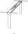
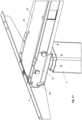
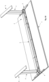
- the height-adjustable table shown in fig. 18 comprises a table top 1 and a frame 2 on which the table top is mounted.
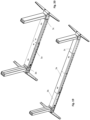
- the frame comprises a length-adjustable longitudinal member 3, two cross members 4,5, one mounted to each end of the longitudinal member, a pair of height-adjustable legs 6,7, also called lifting columns, which with an upper end are mounted to the longitudinal member at either end thereof, and two feet 8,9, one mounted to a lower end of each height-adjustable leg.
- the longitudinal member 3 is constituted by a middle section 3a and two end sections 3b,3c, which are longitudinal displaceably mounted in the middle section 3a for adaption of the length of the longitudinal member to the actual length of the table top.
- the middle section 3a has a U-shaped cross section, where the side walls 10 terminate in an outwardly extending flange 11 which is folded to form a groove 12.
- the two displaceable end sections 3b,3c also have a U-shaped cross section fitting into the middle section 3a and where the side walls 13 terminate in an outwardly extending flange 14 fitting into the groove in the middle section, see figs. 2 and 4 .
- cross member 4,5 To the free ends of the two end sections 3b,3c of the longitudinal member a cross member 4,5 is secured, said cross member 4,5 has a side wall 15, the height of which corresponds to the height of the longitudinal member 3. At the top, the side wall extends into a protruding flange 16, which is level with the flanges 14 of the longitudinal member 3. At the lower edge, the cross member has a bracket 17 with a perpendicular portion 17a protruding from the lower end of the cross member, which at its free edge is terminated in a perpendicular flange 17b.
- the side wall of the cross member has a slit 18,19 at either side of the bracket.
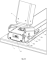
- the cross member 4,5 is mounted on the longitudinal member 3 by inserting the perpendicular flange 17b into a cross slit 20 intended for that purpose in the bottom of the longitudinal member 3, while the slits 18,19 in the side wall 15 of the cross member grip over protruding flanges 21,22 intended for that purpose in the side walls of the longitudinal member 3, see fig. 10 .
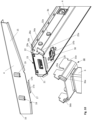
- a pawl unit 23 is mounted which comprises a housing 24, the outer shape of which corresponds to the internal shape of the longitudinal member.
- Two pawls 25a,25b are embedded in the housing 24, said pawls 25a,25b protrude through a fissure 26a,26b in each side of the housing.
- the two pawls are spring-loaded by a coil spring 27, mounted between the two pawls.
- a recess 28a,28b in each side for the two pawls.
- the two pawls When the housing 24 with the two pawls is inserted into the longitudinal member 3, the two pawls will automatically, due to the pre-tensioning of the spring be pressed out through the two fissures in the side of the longitudinal member.
- the housing 24 is further retained by a cam 29a,29b on each side of the housing, said cams will, when mounted, rest in recesses 30a,30b in the side walls of the longitudinal member intended for that purpose, see figs. 5-8 .
- the height-adjustable legs 6,7 comprise three telescopic profiles, namely an outer profile 6a, an intermediate profile 6b and an inner profile 6c, where the lower end of the outer profile has a bottom part with screw holes for mounting of a foot 8,9.
- a mounting bracket 31 for mounting of the leg to the longitudinal profile is secured to the upper end.
- the mounting bracket 31 has a U-shaped cross section and has an internal cross section corresponding to the outer cross section of the longitudinal member 3, such that this can rest therein.
- For mounting of the longitudinal member 3 this is on the outer side equipped with a pair of axle journals 32a,32b for cooperating with a pair of recesses 33a,33b intended for that purpose located at the end of the mounting bracket 31 of the leg facing towards the center of the longitudinal member 3.
- the leg 6 When the leg 6 is mounted, this is held in a horizontal position against the longitudinal member 3, see fig. 12 , such that its mounting bracket with the recesses 33a,33b is placed over the two axle journals 32a,32b on the outer side of the longitudinal member 3.
- the external side of the longitudinal member is equipped with a pair of journals 34a,34b for cooperating with a pair of tracks 35a,35b in the mounting bracket 30, said tracks run from the upper edge of the mounting bracket.
- the axle journals 32a,32b and the cooperating recesses 33a,33b in the end of the mounting bracket 30 lock the leg against movement in the vertical direction, while the journals 34a,34b and the cooperating tracks 35a,35b from the upper edge of the mounting bracket retains this against movement in the axial direction of the longitudinal member 3.
- the mounting bracket is locked at the front end by means of the pawl unit 23 at the end of the longitudinal member as two slits 36a,36b, intended for engagement with the two pawls 25a,25b which protrude from the side walls in the longitudinal member, are constructed in the sidewalls of the mounting bracket 30.
- the securing of the leg is as a rule stabilized in that the U-shaped bracket 30 with the side walls is is fitted in a close-fitting manner over the side of the longitudinal member 3 and in addition, the upper edge of the U-shaped bracket 30 rests against the lower edge of the protruding flanges 14 on each side of the longitudinal member 3b.
- the legs 6,7 also called lifting columns, are equipped with a driving mechanism in the form of a spindle unit comprising a solid spindle and a hollow spindle as well as a drive tube.
- the spindle unit is with its one side secured to the outer tube and with the other end secured to the inner profile, while the intermediate profile is secured to the hollow spindle such that it is guided synchronously with the inner profile.
- a pin 37a of a spline coupling is secured to the upper end of the drive tube.
- a hole 38 is constructed, which the spline coupling pin protrudes through, see fig. 12 .
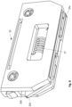
- a motor unit 39 is mounted, which comprises a housing 40 with a cover 41, see fig. 13 .
- the housing is divided into two chambers 40a,40b, one for the motor unit 39 and another for the electrical control, which comprises a printed circuit board 42, among other things with a mains socket 43 which is accessible through a hole in the side of the longitudinal member 3.
- a mains socket 43 which is accessible through a hole in the side of the longitudinal member 3.
- two low voltage sockets 44 Separate from the mains socket are two low voltage sockets 44, which are accessible through a hole in the other side of the longitudinal member.
- the motor unit 39 comprises an electric motor 45 and a gear 46 in the form of a worm gear with a worm in extension of the motor shaft and in engagement with a worm wheel.
- the other part of the spline coupling is constructed, i.e. a recess 37b for receiving the spline coupling pin 37a, see fig. 12 .
- the motor unit is connected to a drive shaft 47 which runs through the longitudinal member 3 to the other leg 7, see fig. 1 .
- a toothed wheel is mounted, which is in engagement with the worm wheel of the motor unit.
- the drive shaft 47 is in engagement with a corresponding worm gear 48, where the end of the drive shaft is in engagement with the worm, which further is in engagement with the worm wheel, which through a spline coupling is in engagement with the drive unit of the legs 5.
- the drive shaft 47 is telescopic, such that this in a corresponding manner as the longitudinal member 3 can be adapted to the present length of a given table.
- the drive shaft 47 consists of three parts, where the two parts 47b,47c, which are in engagement with the motor unit 39 and the gear 48 at the other end of the longitudinal member, respectively, are tubes, while the middle section 47a is a solid rod, which with the ends is received in the two tube portions 47b,47c.
- the cross section is multi-edged such that the rotation from the motor can be transferred to the drive unit for the leg at the other end of the longitudinal member.
- the drive mechanism for bringing about the telescopic movement of the legs comprises a spindle unit, consisting of a solid spindle and a hollow spindle both having external threads.
- a spindle nut for the solid spindle is secured, said spindle nut is constructed as a bushing with internal threads.
- the hollow spindle is surrounded by a drive tube furnished with a number of axially running grooves on its inner side.
- a ring is secured to the external side thereof, said ring having a number of fins on its outer side, which protrude into the grooves of the drive tube.
- a support tube surrounds the drive tube and at the lower end of the support tube a spindle nut for the hollow spindle is secured.
- the spindle nut is in the shape of a bushing with internal threads.
- the invention is here in particular mentioned in connection with sit-stand desks, but it is understood that the invention can also be used in connection with other types of tables such as work tables, counters, kitchen tables etc.
Landscapes
- Mutual Connection Of Rods And Tubes (AREA)
- Tables And Desks Characterized By Structural Shape (AREA)
- Rehabilitation Tools (AREA)
- Accommodation For Nursing Or Treatment Tables (AREA)
- Legs For Furniture In General (AREA)
Claims (16)
- Rahmen für Sitz-Steh-Tische, umfassend ein längliches Element (3), zwei höhenverstellbare Beine (6, 7) mit mindestens zwei Teleskopprofilen, und zwar ein äußeres und ein inneres Profil, und mit einem Antriebsmechanismus, der von einer gemeinsamen Motoreinheit (39) angetrieben wird, umfassend einen Elektromotor (45) und ein Getriebe (46), wobei die gemeinsame Motoreinheit in dem länglichen Element (3) angeordnet und mit dem Antriebsmechanismus in den höhenverstellbaren Beinen (6, 7) verbunden ist, wobei eine Montageklammer (31) zum Montieren des Beins (6, 7) an dem länglichen Element (3) an dem oberen Ende des Profils befestigt ist, wobei die Außenseite des länglichen Elements (3) mit einem Paar Achszapfen (32a, 32b) ausgestattet ist, um mit einem Paar Aussparungen (33a, 33b) zu kooperieren, die sich an dem der Mitte des länglichen Elements (3) zugewandten Ende der Montageklammer (31) des Beins (6, 7) befinden, wobei die Außenseite des länglichen Elements (3) mit einem Paar Zapfen (34a, 34b) ausgestattet ist, die mit einem Paar Führungen (35a, 35b) in der Montageklammer (31) kooperieren, wobei sich die Führungen von der oberen Kante der Montageklammer erstrecken.
- Rahmen nach Anspruch 1, gekennzeichnet dadurch, dass die Montageklammer (31) U-förmig ist und einen Innenquerschnitt aufweist, der dem äußeren Querschnitt des länglichen Elements (3) entspricht, sodass das längliche Element in diesem aufliegen kann.
- Rahmen nach einem oder mehreren der Ansprüche 1-2, gekennzeichnet dadurch, dass er eine Klaueneinheit (23) umfasst, die an dem Ende des länglichen Elements (3) angeordnet ist, da die Seitenwände der Montageklammer (31) mit zwei Rillen (36a, 36b) aufgebaut sind, die zum Eingriff mit den zwei Klauen (35a, 35b), die von der Seitenwand des länglichen Elements (3) hervorstehen, vorgesehen sind.
- Rahmen nach Anspruch 3, gekennzeichnet dadurch, dass die Klaueneinheit (23) ein Gehäuse (24) umfasst, dessen Außenform der Innenform des Querelements (3) entspricht, und dass die zwei in das Gehäuse eingebetteten Klauen (25a, 25b) durch eine Spalte (26a, 26b) in jeder Seite des Gehäuses (24) vorspringen, und dass die zwei Klauen durch eine Spiralfeder (27), die zwischen den zwei Klauen montiert ist, federgespannt sind.
- Rahmen nach Anspruch 4, gekennzeichnet dadurch, dass das Gehäuse (24) der Klaueneinheit (23) zusätzlich zu den zwei Klauen (25a, 25b) außerdem durch eine Nocke auf jeder Seite des Gehäuses befestigt ist, wobei die Nocken (29a, 29b) im montierten Zustand in Aussparungen (30a, 30b) in den Seitenwänden des länglichen Elements (3), die für diesen Zweck vorgesehen sind, aufliegen.
- Rahmen nach einem oder mehreren der Ansprüche 1-4, gekennzeichnet dadurch, dass das längliche Element (3) aus einem Mittelabschnitt (3a) und zwei Endabschnitten (3b, 3c) besteht, die länglich verschiebbar in dem Mittelabschnitt montiert sind.
- Rahmen nach Anspruch 6, gekennzeichnet dadurch, dass der Mittelabschnitt (3a) einen U-förmigen Querschnitt aufweist, wobei die Seitenwände (10) in einem sich nach außen erstreckenden Flansch (11) enden, welcher dazu gefaltet ist, eine Rille (12) auszubilden, und wobei die Endabschnitte (3b, 3c) auch einen U-förmigen Querschnitt aufweisen, der in den Mittelabschnitt (3a) passt, und wobei die Seitenwände in einen sich nach außen erstreckenden Flansch (14) enden, der in die Rille (12) in dem Mittelabschnitt (3a) passt.
- Rahmen nach einem der Ansprüche 1-7, gekennzeichnet dadurch, dass die gemeinsame Motoreinheit (39) in dem länglichen Element (3) montiert und in Antriebsverbindung mit dem Antriebsmechanismus der höhenverstellbaren Beine (6, 7) ist.
- Rahmen nach Anspruch 8, gekennzeichnet dadurch, dass die gemeinsame Motoreinheit (39) ein Gehäuse (40) mit einem Deckel (41) umfasst.
- Rahmen nach Anspruch 9, gekennzeichnet dadurch, dass das Gehäuse (40) in zwei Kammern (40a, 40b) aufgeteilt ist, eine für die gemeinsame Motoreinheit (39) und eine andere für die elektrische Steuerung, welche eine Leiterplatte (42) umfasst, die unter anderem eine Netzsteckdose (43) umfasst, die durch ein Loch in der Seite des länglichen Elements (3) zugänglich ist, und getrennt von der Netzsteckdose (43) gibt es mindestens eine Niederspannungssteckdose (44), die durch ein Loch in der anderen Seite des länglichen Elements (3) zugänglich ist.
- Rahmen nach Anspruch 8, gekennzeichnet dadurch, dass die gemeinsame Motoreinheit (39) einen Elektromotor (45) und ein Getriebe (46) in der Form eines Schneckengetriebes umfasst, das eine Schnecke als Fortsetzung der Motorwelle und im Eingriff mit einem Schneckenrad aufweist, und wobei die Seite des Schneckenrades ausgerüstet ist mit einem Teil (37b) einer Keilverbindung zum Kooperieren mit dem anderen Teil (37a) der Keilverbindung, das auf dem Antriebsmechanismus der Beine (6, 7) angeordnet ist.
- Rahmen nach Anspruch 8, gekennzeichnet dadurch, dass die gemeinsame Motoreinheit (39) in Verbindung mit einer Antriebswelle (47) ist, die durch das längliche Element (3) zu mindestens einem der Beine (6, 7) verläuft.
- Rahmen nach Anspruch 12, gekennzeichnet dadurch, dass ein Zahnrad an dem Ende der Antriebswelle montiert ist, wobei das Zahnrad im Eingriff mit dem Schneckenrad der gemeinsamen Motoreinheit (39) ist, und dass das gegenüberliegende Ende der Antriebswelle in Verbindung mit einem entsprechenden Schneckengetriebe (48) ist, wobei das Ende der Antriebswelle im Eingriff mit der Schnecke ist, welche ferner im Eingriff mit dem Schneckenrad ist, welches durch eine Keilkopplung im Eingriff mit der Antriebseinheit des Beins (7) ist.
- Rahmen nach Anspruch 12, gekennzeichnet dadurch, dass die Antriebswelle (47) teleskopisch aufgebaut ist, sodass diese in einer entsprechenden Weise zu dem länglichen Element (3) an die aktuelle Länge eines bestimmten Tisches angepasst werden kann.
- Rahmen nach Anspruch 12, gekennzeichnet dadurch, dass die Antriebswelle (47) aus drei Teilen besteht, wobei die zwei Teile (47b, 47c), die jeweils im Eingriff mit der gemeinsamen Motoreinheit (39) und dem Getriebe (48) in der anderen Seite des länglichen Elements sind, Rohre sind, während der Mittelabschnitt (47a) eine massive Stange ist, die mit den Enden in den beiden Rohren (47b, 47c) aufgenommen ist, und dass der Querschnitt polygonal ist, sodass die Drehung von dem Motor (45) auf die Antriebseinheit für das Bein (7) auf der anderen Seite des länglichen Elements (3) übertragen werden kann.
- Höhenverstellbarer Tisch, umfassend einen Rahmen nach einem oder mehreren der Ansprüche 1-15.
Applications Claiming Priority (2)
| Application Number | Priority Date | Filing Date | Title |
|---|---|---|---|
| DKPA201800117 | 2018-03-14 | ||
| PCT/DK2019/000094 WO2019174686A2 (en) | 2018-03-14 | 2019-03-13 | Frame for a table |
Publications (2)
| Publication Number | Publication Date |
|---|---|
| EP3764841A2 EP3764841A2 (de) | 2021-01-20 |
| EP3764841B1 true EP3764841B1 (de) | 2024-12-25 |
Family
ID=66589154
Family Applications (1)
| Application Number | Title | Priority Date | Filing Date |
|---|---|---|---|
| EP19724735.6A Active EP3764841B1 (de) | 2018-03-14 | 2019-03-13 | Gestell für einen tisch |
Country Status (7)
| Country | Link |
|---|---|
| US (2) | US11357320B2 (de) |
| EP (1) | EP3764841B1 (de) |
| JP (1) | JP7397799B2 (de) |
| CN (1) | CN111867425B (de) |
| CA (1) | CA3092777A1 (de) |
| DK (1) | DK3764841T3 (de) |
| WO (1) | WO2019174686A2 (de) |
Cited By (1)
| Publication number | Priority date | Publication date | Assignee | Title |
|---|---|---|---|---|
| DE102025113436A1 (de) | 2025-04-04 | 2026-04-30 | Kesseböhmer Holding Kg | Traggestell eines Möbels, Möbel mit einem solchen Traggestell und Verfahren zum Sichern und Entsichern einer klappbaren Säule des Traggestells |
Families Citing this family (28)
| Publication number | Priority date | Publication date | Assignee | Title |
|---|---|---|---|---|
| US11096481B2 (en) * | 2017-07-28 | 2021-08-24 | Varidesk, Llc | Motorized adjustable height table |
| EP3764841B1 (de) * | 2018-03-14 | 2024-12-25 | Linak A/S | Gestell für einen tisch |
| CN112074210B (zh) | 2018-05-04 | 2021-11-16 | 珀品有限公司 | 免用工具安装的附接组件 |
| CN111436746B (zh) * | 2020-04-23 | 2024-11-12 | 常州市凯迪电器股份有限公司 | 一种快速组装的桌面支架 |
| CN111920181B (zh) * | 2020-07-21 | 2025-12-23 | 常州市凯迪电器股份有限公司 | 模块化线性致动器及升降桌 |
| DE102020211087A1 (de) | 2020-09-02 | 2022-03-03 | Veyhl Gmbh | Tischgestell und Tisch |
| DE202020105069U1 (de) | 2020-09-02 | 2021-12-03 | Veyhl Gmbh | Tischgestell und Tisch |
| CN213820289U (zh) * | 2020-11-10 | 2021-07-30 | 德沃康科技集团有限公司 | 一种折叠桌架及折叠桌 |
| CN112741415A (zh) * | 2021-01-19 | 2021-05-04 | 宁波汇五洲智能科技有限公司 | 一种拆装便捷的升降桌 |
| US11419410B1 (en) * | 2021-02-05 | 2022-08-23 | Shanghai Tengfei Communication Equipment Industry Co., Ltd | Lifting table |
| CN112815044A (zh) * | 2021-02-07 | 2021-05-18 | 德沃康科技集团有限公司 | 一种一电二驱的同步驱动装置 |
| USD943324S1 (en) * | 2021-04-12 | 2022-02-15 | Kanuodisi (Guangzhou) Furniture Co., Ltd. | Desk frame |
| TWM618980U (zh) * | 2021-05-28 | 2021-11-01 | 第一傳動科技股份有限公司 | 輕量化電動桌腳架 |
| US11490726B1 (en) * | 2021-07-01 | 2022-11-08 | Zhejiang Jiecang Linear Motion Technology Co., Ltd. | Folding table stand, folding table, and method for assembling the same |
| TWM622096U (zh) * | 2021-07-21 | 2022-01-11 | 第一傳動科技股份有限公司 | 升降桌腳架 |
| EP4173520A1 (de) * | 2021-10-26 | 2023-05-03 | Actiforce International B.V. | Höhenverstellbares büromöbelstück |
| CN217390195U (zh) * | 2021-11-10 | 2022-09-09 | 常州市凯迪电器股份有限公司 | 一种带快速安装结构的升降桌支架及升降桌 |
| TWI788178B (zh) * | 2022-01-04 | 2022-12-21 | 第一傳動科技股份有限公司 | 電動桌、電動桌腳架及其輕量化橫樑結構 |
| CN217565255U (zh) | 2022-03-01 | 2022-10-14 | 浙江捷昌线性驱动科技股份有限公司 | 电动升降桌 |
| US11925265B2 (en) * | 2022-03-30 | 2024-03-12 | Loctek Ergonomic Technology Corp. | Transmission rod assembly and a height-adjustable desk thereof |
| TWI790975B (zh) * | 2022-06-06 | 2023-01-21 | 第一傳動科技股份有限公司 | 電動桌腳架之橫樑結構 |
| CN217851805U (zh) | 2022-07-08 | 2022-11-22 | 南通市久正人体工学股份有限公司 | 一种三腿电动升降桌 |
| US20250213032A1 (en) * | 2022-08-12 | 2025-07-03 | Qidong Vision Mounts Manufacturing Co.,Ltd. | Electric height-adjustable desk |
| CN115153181A (zh) * | 2022-08-12 | 2022-10-11 | 南通市久正人体工学股份有限公司 | 一种电动升降桌 |
| US20240268552A1 (en) * | 2023-02-10 | 2024-08-15 | Knoll, Inc. | Channel assembly to reduce worksurface sag |
| WO2024220118A1 (en) * | 2023-04-18 | 2024-10-24 | Workrite Ergonomics, Llc | Table frame with integrated mounting flanges |
| KR102850469B1 (ko) * | 2024-06-12 | 2025-08-26 | 주식회사 디자인칼라스 | 배선정리함이 구비된 책상 |
| WO2026067063A1 (zh) * | 2024-09-30 | 2026-04-02 | 乐歌人体工学科技股份有限公司 | 一种桌子 |
Citations (2)
| Publication number | Priority date | Publication date | Assignee | Title |
|---|---|---|---|---|
| DE3049357A1 (de) * | 1980-12-29 | 1982-07-29 | Horn GmbH & Co KG, 7062 Rudersberg | Hoehenverstellbarer tisch |
| US9848696B2 (en) * | 2016-04-26 | 2017-12-26 | Powdermet Inc. | Electric table stand, coupling thereof, and electric table with electric table stand |
Family Cites Families (38)
| Publication number | Priority date | Publication date | Assignee | Title |
|---|---|---|---|---|
| JPS60139924U (ja) * | 1984-02-27 | 1985-09-17 | コクヨ株式会社 | 軸接手 |
| JPH07148023A (ja) * | 1993-11-26 | 1995-06-13 | Komura Seisakusho:Kk | テーブル |
| US6182583B1 (en) * | 1997-09-08 | 2001-02-06 | John E. Larson | Height adjustable pedestal for chairs and tables |
| EP1079511A1 (de) | 1999-08-26 | 2001-02-28 | Linak A/S | Stromversorgung für Gleichstrommotoren |
| TW453155U (en) * | 2000-10-19 | 2001-09-01 | Kai Jr Entpr Co Ltd | Folding structure of support leg |
| EP1401304B1 (de) | 2001-07-04 | 2007-03-07 | Linak A/S | Antriebseinheit, vorzugsweise für hubsäulen für höhenverstellbare tische, und hubsäule |
| CN1784937B (zh) | 2003-05-06 | 2011-09-28 | 利纳克有限公司 | 致动器 |
| US7908981B2 (en) * | 2007-01-31 | 2011-03-22 | Michael Agee | Height adjustable table |
| NL2001472C2 (nl) * | 2008-04-11 | 2009-10-13 | Vehold B V | Verstelinrichting. |
| EP2160958B1 (de) * | 2008-09-08 | 2016-06-29 | Linak A/S | Höhenverstellbarer Tisch |
| SE0802030L (sv) * | 2008-09-24 | 2009-11-17 | Swedestyle Ab | Anordning för montering av en bordsskiva på ett stativ med drivorgan |
| DK2290260T3 (da) * | 2009-08-31 | 2013-01-07 | Kih Utveckling Ab | Lineær aktuator indbefattende en endestopdetekteringsenhed |
| US8967054B2 (en) * | 2011-06-03 | 2015-03-03 | Kimball International, Inc. | Office desking system |
| US9038549B1 (en) * | 2012-06-01 | 2015-05-26 | Humanscale Corporation | Height adjustable table |
| CN103315519B (zh) * | 2013-06-28 | 2015-03-25 | 浙江捷昌线性驱动科技股份有限公司 | 一种升降桌或凳及可折叠支架 |
| DK2873344T3 (en) * | 2013-11-18 | 2017-07-24 | Usm Holding Ag | Furniture with height adjustable legs |
| TWM486995U (zh) * | 2014-04-03 | 2014-10-01 | Timotion Technology Co Ltd | 易於展收的電動桌腳架 |
| DK3148372T3 (da) * | 2014-05-26 | 2021-07-19 | Linak As | Bærende ramme for et møbel |
| JP6647219B2 (ja) * | 2014-05-26 | 2020-02-14 | リナック エー/エス | 家具用支持フレーム |
| WO2015180724A1 (en) * | 2014-05-26 | 2015-12-03 | Linak A/S | Height-adjustable supporting frame |
| TWM496957U (zh) * | 2014-10-23 | 2015-03-11 | Chun-Tsair Wang | 電動升降桌之驅動器固定裝置 |
| CH710641B1 (de) * | 2015-01-21 | 2019-07-15 | Licenscom Gmbh | Höhenverstellbarer Nagelkosmetik-Arbeitstisch mit integrierter Staubabsaugung. |
| DE102015105588A1 (de) * | 2015-04-13 | 2016-10-13 | Dewertokin Gmbh | Tischgestell für einen Tisch |
| DE102015105827A1 (de) * | 2015-04-16 | 2016-10-20 | Dewertokin Gmbh | Tischgestell für einen Tisch |
| DE202016002581U1 (de) * | 2015-04-30 | 2016-05-09 | Kesseböhmer Produktions GmbH & Co. KG | System zum Befestigen eines Möbelbeins an einem Möbel |
| DE102015216821B4 (de) * | 2015-09-02 | 2022-02-03 | Kesseböhmer Produktions GmbH & Co. KG | Möbelrahmen zum Sichern einer klappbaren Möbelsäule |
| US20170071332A1 (en) * | 2015-09-15 | 2017-03-16 | Next Technologies, Inc. | Height Adjustable Desks with Ultraviolet Light Irradiation of Keyboard Tray |
| DE102016101955A1 (de) * | 2016-02-04 | 2017-08-10 | Karsten Laing | Elektrisch verstellbares Möbelstück |
| US9730512B1 (en) * | 2016-02-10 | 2017-08-15 | Veyhl Gmbh | Table frame and table |
| EP3311692A1 (de) * | 2016-10-20 | 2018-04-25 | Vitra Patente AG | Höhenverstellbares gestell mit klappbaren beinelementen |
| SE1651506A1 (en) * | 2016-11-17 | 2018-04-10 | Polstiernan Ind Ab | A collapsible table stand, and a table including such a table stand |
| US10791826B2 (en) * | 2017-03-31 | 2020-10-06 | Twin-Star International, Inc. | Adjustable height desk system |
| US11096481B2 (en) * | 2017-07-28 | 2021-08-24 | Varidesk, Llc | Motorized adjustable height table |
| US20190069669A1 (en) * | 2017-09-01 | 2019-03-07 | David R. Hall | Elliptically Rotating Cable Organizing Device |
| US10842258B2 (en) * | 2017-09-18 | 2020-11-24 | Fellowes, Inc. | Variable height platform system |
| TWM560241U (zh) * | 2017-10-26 | 2018-05-21 | Timotion Technology Co Ltd | 易於組裝的升降桌腳架 |
| DE102018104195A1 (de) * | 2018-02-23 | 2019-08-29 | Logicdata Electronic & Software Entwicklungs Gmbh | Möbelstück, Verfahren zum Kalibrieren eines Aktuators und Verfahren zum Verstellen einer Komponente eines Möbelstücks |
| EP3764841B1 (de) * | 2018-03-14 | 2024-12-25 | Linak A/S | Gestell für einen tisch |
-
2019
- 2019-03-13 EP EP19724735.6A patent/EP3764841B1/de active Active
- 2019-03-13 JP JP2020547199A patent/JP7397799B2/ja active Active
- 2019-03-13 WO PCT/DK2019/000094 patent/WO2019174686A2/en not_active Ceased
- 2019-03-13 CA CA3092777A patent/CA3092777A1/en active Pending
- 2019-03-13 DK DK19724735.6T patent/DK3764841T3/da active
- 2019-03-13 US US16/977,344 patent/US11357320B2/en active Active
- 2019-03-13 CN CN201980018974.3A patent/CN111867425B/zh active Active
-
2022
- 2022-05-31 US US17/828,403 patent/US11839301B2/en active Active
Patent Citations (2)
| Publication number | Priority date | Publication date | Assignee | Title |
|---|---|---|---|---|
| DE3049357A1 (de) * | 1980-12-29 | 1982-07-29 | Horn GmbH & Co KG, 7062 Rudersberg | Hoehenverstellbarer tisch |
| US9848696B2 (en) * | 2016-04-26 | 2017-12-26 | Powdermet Inc. | Electric table stand, coupling thereof, and electric table with electric table stand |
Cited By (1)
| Publication number | Priority date | Publication date | Assignee | Title |
|---|---|---|---|---|
| DE102025113436A1 (de) | 2025-04-04 | 2026-04-30 | Kesseböhmer Holding Kg | Traggestell eines Möbels, Möbel mit einem solchen Traggestell und Verfahren zum Sichern und Entsichern einer klappbaren Säule des Traggestells |
Also Published As
| Publication number | Publication date |
|---|---|
| CN111867425A (zh) | 2020-10-30 |
| DK3764841T3 (da) | 2025-03-31 |
| WO2019174686A3 (en) | 2019-10-24 |
| JP2021515653A (ja) | 2021-06-24 |
| WO2019174686A2 (en) | 2019-09-19 |
| US20210100355A1 (en) | 2021-04-08 |
| US11357320B2 (en) | 2022-06-14 |
| EP3764841A2 (de) | 2021-01-20 |
| CA3092777A1 (en) | 2019-09-19 |
| CN111867425B (zh) | 2023-11-10 |
| JP7397799B2 (ja) | 2023-12-13 |
| US11839301B2 (en) | 2023-12-12 |
| US20220287452A1 (en) | 2022-09-15 |
Similar Documents
| Publication | Publication Date | Title |
|---|---|---|
| EP3764841B1 (de) | Gestell für einen tisch | |
| US10004326B2 (en) | Supporting frame for a piece of furniture | |
| EP3148372B1 (de) | Stützrahmen für ein möbelstück | |
| EP1884400B1 (de) | Haltevorrichtung für einen Sicherheitskindersitz in einem Fahrzeug | |
| EP1353128B1 (de) | In Haushaltsgeräten, insbesondere in Gar- und Backöfen verwendbarer, breitenverstellbarer Trägerrahmen | |
| RU2557728C2 (ru) | Направляющая для выдвижения ящика | |
| JP2013518624A (ja) | 引き出し用引抜きガイド | |
| US20120248910A1 (en) | Linear actuator | |
| EP3769646B1 (de) | Schubladenausziehführung mit drei abschnitten | |
| EP1639926A1 (de) | Kaffeemaschine mit einer höhenverstellbaren Auffangschale | |
| JP2013518623A (ja) | 引き出しの側部調整機能を有する結合装置 | |
| EP3148373A1 (de) | Höhenverstellbarer stützrahmen | |
| KR20100012201A (ko) | 상판 각도 조절식 테이블 | |
| KR100881257B1 (ko) | 높낮이 조절 책걸상 | |
| CN120769717A (zh) | 平移-旋转配件以及家具或家用电器元件 | |
| WO2002039848A1 (en) | Linear actuator | |
| KR19990008025U (ko) | 선반 설치용 지지장치 | |
| DE60320472T2 (de) | Unterkonstruktion für höhenverstellebaren Tisch | |
| AT10095U1 (de) | Vorrichtung zur höhenverstellung einer arbeitsplatte eines küchenmöbels | |
| KR200423262Y1 (ko) | 높낮이 조절 책걸상 | |
| SE2351396A1 (en) | Underframe and table |
Legal Events
| Date | Code | Title | Description |
|---|---|---|---|
| STAA | Information on the status of an ep patent application or granted ep patent |
Free format text: STATUS: UNKNOWN |
|
| STAA | Information on the status of an ep patent application or granted ep patent |
Free format text: STATUS: THE INTERNATIONAL PUBLICATION HAS BEEN MADE |
|
| PUAI | Public reference made under article 153(3) epc to a published international application that has entered the european phase |
Free format text: ORIGINAL CODE: 0009012 |
|
| STAA | Information on the status of an ep patent application or granted ep patent |
Free format text: STATUS: REQUEST FOR EXAMINATION WAS MADE |
|
| 17P | Request for examination filed |
Effective date: 20201009 |
|
| AK | Designated contracting states |
Kind code of ref document: A2 Designated state(s): AL AT BE BG CH CY CZ DE DK EE ES FI FR GB GR HR HU IE IS IT LI LT LU LV MC MK MT NL NO PL PT RO RS SE SI SK SM TR |
|
| AX | Request for extension of the european patent |
Extension state: BA ME |
|
| DAV | Request for validation of the european patent (deleted) | ||
| DAX | Request for extension of the european patent (deleted) | ||
| RAP3 | Party data changed (applicant data changed or rights of an application transferred) |
Owner name: LINAK A/S |
|
| STAA | Information on the status of an ep patent application or granted ep patent |
Free format text: STATUS: EXAMINATION IS IN PROGRESS |
|
| 17Q | First examination report despatched |
Effective date: 20230222 |
|
| GRAP | Despatch of communication of intention to grant a patent |
Free format text: ORIGINAL CODE: EPIDOSNIGR1 |
|
| STAA | Information on the status of an ep patent application or granted ep patent |
Free format text: STATUS: GRANT OF PATENT IS INTENDED |
|
| INTG | Intention to grant announced |
Effective date: 20240717 |
|
| GRAS | Grant fee paid |
Free format text: ORIGINAL CODE: EPIDOSNIGR3 |
|
| GRAA | (expected) grant |
Free format text: ORIGINAL CODE: 0009210 |
|
| STAA | Information on the status of an ep patent application or granted ep patent |
Free format text: STATUS: THE PATENT HAS BEEN GRANTED |
|
| AK | Designated contracting states |
Kind code of ref document: B1 Designated state(s): AL AT BE BG CH CY CZ DE DK EE ES FI FR GB GR HR HU IE IS IT LI LT LU LV MC MK MT NL NO PL PT RO RS SE SI SK SM TR |
|
| REG | Reference to a national code |
Ref country code: GB Ref legal event code: FG4D |
|
| REG | Reference to a national code |
Ref country code: CH Ref legal event code: EP |
|
| REG | Reference to a national code |
Ref country code: DE Ref legal event code: R096 Ref document number: 602019063934 Country of ref document: DE |
|
| REG | Reference to a national code |
Ref country code: IE Ref legal event code: FG4D |
|
| REG | Reference to a national code |
Ref country code: DK Ref legal event code: T3 Effective date: 20250325 |
|
| REG | Reference to a national code |
Ref country code: SE Ref legal event code: TRGR |
|
| REG | Reference to a national code |
Ref country code: LT Ref legal event code: MG9D |
|
| PG25 | Lapsed in a contracting state [announced via postgrant information from national office to epo] |
Ref country code: FI Free format text: LAPSE BECAUSE OF FAILURE TO SUBMIT A TRANSLATION OF THE DESCRIPTION OR TO PAY THE FEE WITHIN THE PRESCRIBED TIME-LIMIT Effective date: 20241225 |
|
| PG25 | Lapsed in a contracting state [announced via postgrant information from national office to epo] |
Ref country code: BG Free format text: LAPSE BECAUSE OF FAILURE TO SUBMIT A TRANSLATION OF THE DESCRIPTION OR TO PAY THE FEE WITHIN THE PRESCRIBED TIME-LIMIT Effective date: 20241225 |
|
| PG25 | Lapsed in a contracting state [announced via postgrant information from national office to epo] |
Ref country code: NO Free format text: LAPSE BECAUSE OF FAILURE TO SUBMIT A TRANSLATION OF THE DESCRIPTION OR TO PAY THE FEE WITHIN THE PRESCRIBED TIME-LIMIT Effective date: 20250325 |
|
| PG25 | Lapsed in a contracting state [announced via postgrant information from national office to epo] |
Ref country code: GR Free format text: LAPSE BECAUSE OF FAILURE TO SUBMIT A TRANSLATION OF THE DESCRIPTION OR TO PAY THE FEE WITHIN THE PRESCRIBED TIME-LIMIT Effective date: 20250326 Ref country code: LV Free format text: LAPSE BECAUSE OF FAILURE TO SUBMIT A TRANSLATION OF THE DESCRIPTION OR TO PAY THE FEE WITHIN THE PRESCRIBED TIME-LIMIT Effective date: 20241225 |
|
| PG25 | Lapsed in a contracting state [announced via postgrant information from national office to epo] |
Ref country code: RS Free format text: LAPSE BECAUSE OF FAILURE TO SUBMIT A TRANSLATION OF THE DESCRIPTION OR TO PAY THE FEE WITHIN THE PRESCRIBED TIME-LIMIT Effective date: 20250325 |
|
| REG | Reference to a national code |
Ref country code: NL Ref legal event code: MP Effective date: 20241225 |
|
| PG25 | Lapsed in a contracting state [announced via postgrant information from national office to epo] |
Ref country code: NL Free format text: LAPSE BECAUSE OF FAILURE TO SUBMIT A TRANSLATION OF THE DESCRIPTION OR TO PAY THE FEE WITHIN THE PRESCRIBED TIME-LIMIT Effective date: 20241225 |
|
| REG | Reference to a national code |
Ref country code: AT Ref legal event code: MK05 Ref document number: 1753428 Country of ref document: AT Kind code of ref document: T Effective date: 20241225 |
|
| PG25 | Lapsed in a contracting state [announced via postgrant information from national office to epo] |
Ref country code: SM Free format text: LAPSE BECAUSE OF FAILURE TO SUBMIT A TRANSLATION OF THE DESCRIPTION OR TO PAY THE FEE WITHIN THE PRESCRIBED TIME-LIMIT Effective date: 20241225 |
|
| PG25 | Lapsed in a contracting state [announced via postgrant information from national office to epo] |
Ref country code: PL Free format text: LAPSE BECAUSE OF FAILURE TO SUBMIT A TRANSLATION OF THE DESCRIPTION OR TO PAY THE FEE WITHIN THE PRESCRIBED TIME-LIMIT Effective date: 20241225 |
|
| PG25 | Lapsed in a contracting state [announced via postgrant information from national office to epo] |
Ref country code: ES Free format text: LAPSE BECAUSE OF FAILURE TO SUBMIT A TRANSLATION OF THE DESCRIPTION OR TO PAY THE FEE WITHIN THE PRESCRIBED TIME-LIMIT Effective date: 20241225 |
|
| PG25 | Lapsed in a contracting state [announced via postgrant information from national office to epo] |
Ref country code: IS Free format text: LAPSE BECAUSE OF FAILURE TO SUBMIT A TRANSLATION OF THE DESCRIPTION OR TO PAY THE FEE WITHIN THE PRESCRIBED TIME-LIMIT Effective date: 20250425 |
|
| PG25 | Lapsed in a contracting state [announced via postgrant information from national office to epo] |
Ref country code: PT Free format text: LAPSE BECAUSE OF FAILURE TO SUBMIT A TRANSLATION OF THE DESCRIPTION OR TO PAY THE FEE WITHIN THE PRESCRIBED TIME-LIMIT Effective date: 20250428 |
|
| PG25 | Lapsed in a contracting state [announced via postgrant information from national office to epo] |
Ref country code: EE Free format text: LAPSE BECAUSE OF FAILURE TO SUBMIT A TRANSLATION OF THE DESCRIPTION OR TO PAY THE FEE WITHIN THE PRESCRIBED TIME-LIMIT Effective date: 20241225 |
|
| PG25 | Lapsed in a contracting state [announced via postgrant information from national office to epo] |
Ref country code: AT Free format text: LAPSE BECAUSE OF FAILURE TO SUBMIT A TRANSLATION OF THE DESCRIPTION OR TO PAY THE FEE WITHIN THE PRESCRIBED TIME-LIMIT Effective date: 20241225 Ref country code: RO Free format text: LAPSE BECAUSE OF FAILURE TO SUBMIT A TRANSLATION OF THE DESCRIPTION OR TO PAY THE FEE WITHIN THE PRESCRIBED TIME-LIMIT Effective date: 20241225 |
|
| PG25 | Lapsed in a contracting state [announced via postgrant information from national office to epo] |
Ref country code: SK Free format text: LAPSE BECAUSE OF FAILURE TO SUBMIT A TRANSLATION OF THE DESCRIPTION OR TO PAY THE FEE WITHIN THE PRESCRIBED TIME-LIMIT Effective date: 20241225 |
|
| PG25 | Lapsed in a contracting state [announced via postgrant information from national office to epo] |
Ref country code: CZ Free format text: LAPSE BECAUSE OF FAILURE TO SUBMIT A TRANSLATION OF THE DESCRIPTION OR TO PAY THE FEE WITHIN THE PRESCRIBED TIME-LIMIT Effective date: 20241225 |
|
| PG25 | Lapsed in a contracting state [announced via postgrant information from national office to epo] |
Ref country code: IT Free format text: LAPSE BECAUSE OF FAILURE TO SUBMIT A TRANSLATION OF THE DESCRIPTION OR TO PAY THE FEE WITHIN THE PRESCRIBED TIME-LIMIT Effective date: 20241225 |
|
| REG | Reference to a national code |
Ref country code: DE Ref legal event code: R097 Ref document number: 602019063934 Country of ref document: DE |
|
| PG25 | Lapsed in a contracting state [announced via postgrant information from national office to epo] |
Ref country code: MC Free format text: LAPSE BECAUSE OF FAILURE TO SUBMIT A TRANSLATION OF THE DESCRIPTION OR TO PAY THE FEE WITHIN THE PRESCRIBED TIME-LIMIT Effective date: 20241225 |
|
| REG | Reference to a national code |
Ref country code: CH Ref legal event code: H13 Free format text: ST27 STATUS EVENT CODE: U-0-0-H10-H13 (AS PROVIDED BY THE NATIONAL OFFICE) Effective date: 20251023 |
|
| PLBE | No opposition filed within time limit |
Free format text: ORIGINAL CODE: 0009261 |
|
| STAA | Information on the status of an ep patent application or granted ep patent |
Free format text: STATUS: NO OPPOSITION FILED WITHIN TIME LIMIT |
|
| PG25 | Lapsed in a contracting state [announced via postgrant information from national office to epo] |
Ref country code: LU Free format text: LAPSE BECAUSE OF NON-PAYMENT OF DUE FEES Effective date: 20250313 |
|
| GBPC | Gb: european patent ceased through non-payment of renewal fee |
Effective date: 20250325 |
|
| 26N | No opposition filed |
Effective date: 20250926 |
|
| REG | Reference to a national code |
Ref country code: BE Ref legal event code: MM Effective date: 20250331 |
|
| PG25 | Lapsed in a contracting state [announced via postgrant information from national office to epo] |
Ref country code: GB Free format text: LAPSE BECAUSE OF NON-PAYMENT OF DUE FEES Effective date: 20250325 |
|
| PG25 | Lapsed in a contracting state [announced via postgrant information from national office to epo] |
Ref country code: FR Free format text: LAPSE BECAUSE OF NON-PAYMENT OF DUE FEES Effective date: 20250331 |
|
| PG25 | Lapsed in a contracting state [announced via postgrant information from national office to epo] |
Ref country code: BE Free format text: LAPSE BECAUSE OF NON-PAYMENT OF DUE FEES Effective date: 20250331 |
|
| PG25 | Lapsed in a contracting state [announced via postgrant information from national office to epo] |
Ref country code: CH Free format text: LAPSE BECAUSE OF NON-PAYMENT OF DUE FEES Effective date: 20250331 |
|
| PG25 | Lapsed in a contracting state [announced via postgrant information from national office to epo] |
Ref country code: IE Free format text: LAPSE BECAUSE OF NON-PAYMENT OF DUE FEES Effective date: 20250313 |
|
| PGFP | Annual fee paid to national office [announced via postgrant information from national office to epo] |
Ref country code: SE Payment date: 20260319 Year of fee payment: 8 |
|
| PGFP | Annual fee paid to national office [announced via postgrant information from national office to epo] |
Ref country code: DK Payment date: 20260324 Year of fee payment: 8 Ref country code: DE Payment date: 20260319 Year of fee payment: 8 |
|
| PG25 | Lapsed in a contracting state [announced via postgrant information from national office to epo] |
Ref country code: HR Free format text: LAPSE BECAUSE OF FAILURE TO SUBMIT A TRANSLATION OF THE DESCRIPTION OR TO PAY THE FEE WITHIN THE PRESCRIBED TIME-LIMIT Effective date: 20241225 |