EP3372114B2 - Kopplungsmechanismus und gleitschienenanordnung für ein möbelteil - Google Patents
Kopplungsmechanismus und gleitschienenanordnung für ein möbelteil Download PDFInfo
- Publication number
- EP3372114B2 EP3372114B2 EP17200267.7A EP17200267A EP3372114B2 EP 3372114 B2 EP3372114 B2 EP 3372114B2 EP 17200267 A EP17200267 A EP 17200267A EP 3372114 B2 EP3372114 B2 EP 3372114B2
- Authority
- EP
- European Patent Office
- Prior art keywords
- base
- slide rail
- rail
- respect
- furniture part
- Prior art date
- Legal status (The legal status is an assumption and is not a legal conclusion. Google has not performed a legal analysis and makes no representation as to the accuracy of the status listed.)
- Active
Links
Images


Classifications
-
- A—HUMAN NECESSITIES
- A47—FURNITURE; DOMESTIC ARTICLES OR APPLIANCES; COFFEE MILLS; SPICE MILLS; SUCTION CLEANERS IN GENERAL
- A47B—TABLES; DESKS; OFFICE FURNITURE; CABINETS; DRAWERS; GENERAL DETAILS OF FURNITURE
- A47B88/00—Drawers for tables, cabinets or like furniture; Guides for drawers
- A47B88/40—Sliding drawers; Slides or guides therefor
- A47B88/423—Fastening devices for slides or guides
- A47B88/427—Fastening devices for slides or guides at drawer side
-
- A—HUMAN NECESSITIES
- A47—FURNITURE; DOMESTIC ARTICLES OR APPLIANCES; COFFEE MILLS; SPICE MILLS; SUCTION CLEANERS IN GENERAL
- A47B—TABLES; DESKS; OFFICE FURNITURE; CABINETS; DRAWERS; GENERAL DETAILS OF FURNITURE
- A47B88/00—Drawers for tables, cabinets or like furniture; Guides for drawers
- A47B88/40—Sliding drawers; Slides or guides therefor
- A47B88/407—Adjustably or detachably mounted drawers
-
- A—HUMAN NECESSITIES
- A47—FURNITURE; DOMESTIC ARTICLES OR APPLIANCES; COFFEE MILLS; SPICE MILLS; SUCTION CLEANERS IN GENERAL
- A47B—TABLES; DESKS; OFFICE FURNITURE; CABINETS; DRAWERS; GENERAL DETAILS OF FURNITURE
- A47B88/00—Drawers for tables, cabinets or like furniture; Guides for drawers
- A47B88/40—Sliding drawers; Slides or guides therefor
- A47B88/423—Fastening devices for slides or guides
- A47B88/427—Fastening devices for slides or guides at drawer side
- A47B2088/4272—Fastening devices for slides or guides at drawer side ensuring a correct connection at the moment when the drawer is coupled to the drawer rail
-
- A—HUMAN NECESSITIES
- A47—FURNITURE; DOMESTIC ARTICLES OR APPLIANCES; COFFEE MILLS; SPICE MILLS; SUCTION CLEANERS IN GENERAL
- A47B—TABLES; DESKS; OFFICE FURNITURE; CABINETS; DRAWERS; GENERAL DETAILS OF FURNITURE
- A47B2210/00—General construction of drawers, guides and guide devices
- A47B2210/0002—Guide construction for drawers
- A47B2210/0051—Guide position
- A47B2210/0054—Adjustment of position of slides
-
- A—HUMAN NECESSITIES
- A47—FURNITURE; DOMESTIC ARTICLES OR APPLIANCES; COFFEE MILLS; SPICE MILLS; SUCTION CLEANERS IN GENERAL
- A47B—TABLES; DESKS; OFFICE FURNITURE; CABINETS; DRAWERS; GENERAL DETAILS OF FURNITURE
- A47B2210/00—General construction of drawers, guides and guide devices
- A47B2210/0002—Guide construction for drawers
- A47B2210/0051—Guide position
- A47B2210/0056—Guide located at the bottom of the drawer
-
- A—HUMAN NECESSITIES
- A47—FURNITURE; DOMESTIC ARTICLES OR APPLIANCES; COFFEE MILLS; SPICE MILLS; SUCTION CLEANERS IN GENERAL
- A47B—TABLES; DESKS; OFFICE FURNITURE; CABINETS; DRAWERS; GENERAL DETAILS OF FURNITURE
- A47B88/00—Drawers for tables, cabinets or like furniture; Guides for drawers
- A47B88/40—Sliding drawers; Slides or guides therefor
- A47B88/49—Sliding drawers; Slides or guides therefor with double extensible guides or parts
Definitions
- the present invention relates to a mechanism and a slide rail. More particularly, the present invention relates to a coupling mechanism and a slide rail assembly for use with a furniture part.
- an undermount drawer slide rail assembly is mounted on the bottom of a drawer and is therefore hidden from view.
- An undermount drawer slide rail assembly typically includes a first rail and a second rail displaceable with respect to the first rail. More specifically, the first rail is mounted on the body of a cabinet, and the second rail is configured to carry or support a drawer so that the drawer can be easily pulled out of and pushed back into the cabinet body through the second rail with respect to the first rail. The undermount drawer slide rail assembly stays hidden at the bottom of the drawer even when the drawer is pulled out of the cabinet body.
- WO 2012/092634 A1 discloses a device for removably coupling a drawer to an extendable rail of a pull-out guide, comprising an adjusting device, by means of which a position of a drawer that is connected to the rail can be adjusted relative to the rail in the lateral direction and/or in the longitudinal direction of the pull-out guide.
- the device has a fixing part that can be fixed to the drawer and a coupling part that can be coupled to the rail, and the fixing part can be moved relative to the coupling part by means of the adjusting device in a linear manner.
- the adjusting device has an adjusting wheel that is rotatably mounted on the coupling part or on the fixing part.
- the object of the invention is achieved by the subject matter of claim 1.
- Advantageous embodiments are disclosed by the dependent claims.
- the present invention relates to a coupling mechanism and a slide rail assembly for use with a furniture part.
- a coupling mechanism adapted for a slide rail includes a first base, a second base, a lateral adjustment member, and a transmission structure.
- the second base is movably mounted on the first base.
- the lateral adjustment member is rotatably mounted on one of the first base and the second base and is configured for adjusting the position of the second base with respect to the first base.
- the transmission structure is configured for converting a rotary movement of the lateral adjustment member into a lateral displacement of the second base with respect to the first base.
- the first base is engagaeable with a coupling base of the slide rail.
- the lateral adjustment member includes an adjusting portion, and the transmission structure is located on one of the first base and the second base.
- the adjusting portion and the transmission structure are configured to work with each other in order to convert a rotary movement of the lateral adjustment member into a lateral displacement of the second base with respect to the first base.
- the adjusting portion is a substantially spiral guide groove
- the transmission structure is a projection located in the guide groove.
- the coupling mechanism further includes a supporting member and a height adjustment member, and that the coupling base is detachably fixed to the slide rail and is detachably engaged with the first base.
- the supporting member includes a supporting portion.
- the height adjustment member is configured for adjusting and thereby displacing the supporting member with respect to the coupling base in order to change the height of the supporting portion of the supporting member with respect to the slide rail through a guiding feature.
- the height adjustment member is rotatably mountable on the coupling base, and the height adjustment member and the supporting member include corresponding threaded structures.
- a slide rail assembly includes a first rail, a second rail, and a coupling mechanism.
- the second rail can be longitudinally displaced with respect to the first rail.
- the coupling mechanism is adjacent to the second rail and includes a first base, a second base, and a lateral adjustment member.
- the second base is movably mounted on the first base.
- the lateral adjustment member is configured for laterally displacing and thereby adjusting the second base with respect to the second rail.
- the first base includes a first feature
- the second base includes a second feature.
- One of the first feature and the second feature includes at least one projection while the other of the first feature and the second feature includes at least one receiving space for receiving the at least one projection.
- the at least one receiving space is larger than the at least one projection so that, with the first feature and the second feature working with each other, the second base can be displaced within a limited range with respect to the first base.
- the slide rail assembly further includes a coupling base detachably fixed to the second rail and detachably engaged with the first base.
- one of the first base and the second base includes a guiding structure to make it easier to displace the second base with respect to the first base.
- the lateral adjustment member is rotatably mounted on the second base and includes an adjusting portion
- the first base includes a transmission structure configured to work with the adjusting portion
- the adjusting portion is a substantially spiral guide groove
- the transmission structure is a projection located in the guide groove
- the coupling mechanism further includes a supporting member and a height adjustment member.
- the supporting member includes a supporting portion.
- the height adjustment member is configured for adjusting and thereby displacing the supporting member with respect to the coupling base in order to change the height of the supporting portion of the supporting member with respect to the second rail through a guiding feature.
- the second rail has a front portion and a rear portion
- the coupling base is mounted on the second rail at a position adjacent to the front portion of the second rail
- the guiding feature includes one of an inclined surface and a curved surface.
- the height adjustment member is rotatably mountable on the coupling base, and the height adjustment member and the supporting member include corresponding longitudinal threaded structures.
- the coupling base includes a cushioning portion
- the first base includes a mounting portion pressed against a first sidewall of the second rail
- the cushioning portion is configured to be pressed against the second base so that a longitudinal gap, if any, between the first base and the second rail can be compensated for by a cushioning movement of the cushioning portion.
- the coupling base includes an elastic portion
- the first base includes an engaging structure.
- the elastic portion of the coupling base is detachably engaged with the engaging structure of the first base and includes at least one first engaging section.
- the engaging structure includes at least one second engaging section corresponding to the first engaging section.
- the slide rail assembly is configured for mounting a furniture part to the body of a furniture cabinet so that the furniture part can be displaced with respect to the furniture cabinet body, wherein the furniture part is releasably mounted with the second rail of the slide rail assembly through the coupling mechanism, and the second base is configured for being connected to the furniture part.
- the lateral position of the furniture part with respect to the furniture cabinet body is changed when the second base is adjusted and thereby displaced with respect to the first base by means of the lateral adjustment member.
- the supporting portion of the supporting member is configured for facing the furniture part.
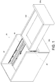
- a piece of furniture 20 includes a first furniture part 22 and at least one second furniture part (also referred to herein as the furniture part).
- two second furniture parts 24a and 24b are provided by way of example.
- Each second furniture part, such as the second furniture part 24a, can be displaced with respect to the first furniture part 22.
- a pair of slide rail assemblies 26 are provided to facilitate displacement of the second furniture part 24a with respect to the first furniture part 22.
- the first furniture part 22 may be the body of a furniture cabinet, and the two second furniture parts 24a and 24b may be drawers; the present invention has no limitation in this regard.
- the pair of slide rail assemblies 26 allow the second furniture part 24a to be movably mounted on the first furniture part 22.
- Each slide rail assembly 26 is an undermount slide rail assembly mounted on the bottom of the second furniture part 24a and includes a first rail 28, a second rail 30 (also referred to herein as the slide rail) longitudinally displaceable with respect to the first rail 28, and preferably also a third rail 32 movably mounted between the first rail 28 and the second rail 30 to increase the distance by which the second rail 30 can be displaced with respect to the first rail 28.
- the first rails 28 are fixedly mounted on the first furniture part 22.
- the second rails 30 are configured for carrying the second furniture part 24a so that the second furniture part 24a can be easily displaced from inside the first furniture part 22 to the outside and pushed back into the first furniture part 22 through the second rails 30.
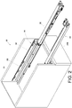
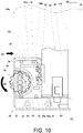
- the slide rail assembly 26 includes a coupling mechanism 34 adjacent to the second rail 30.
- the second rail 30 has a front portion 36a and a rear portion 36b, and the coupling mechanism 34 is mounted on the second rail 30 at a position adjacent to the front portion 36a by way of example.
- the second rail 30 includes a first sidewall 38a, a second sidewall 38b, and a carrying portion 40 located between the first sidewall 38a and the second sidewall 38b.
- the first sidewall 38a, the second sidewall 38b, and the carrying portion 40 jointly define a supporting space 42.
- the second rail 30 preferably further includes a first extension section 44a and a second extension section 44b which are substantially perpendicularly connected to the first sidewall 38a and the second sidewall 38b respectively.
- the first extension section 44a and the second extension section 44b are adjacent to the supporting space 42.
- the second rail 30 preferably further includes a coupling base 82 detachably fixed to the second rail 30.
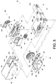
- the coupling mechanism 34 includes a lateral adjustment device 46 and preferably also a height adjustment device 48.
- the lateral adjustment device 46 includes a first base 50, a second base 52, and a lateral adjustment member 54.
- the first base 50 is attached to the second rail 30 (e.g., is engaged with a portion of the second rail 30 that is adjacent to the front portion 36a) via the coupling base 82.
- the first base 50 includes a main body 56, a mounting space 58, and a mounting portion 60.
- the mounting space 58 is located at the main body 56.
- the mounting portion 60 e.g., a hook configured to hook to the first sidewall 38a of the second rail 30 in a detachable manner) is located on one side of the main body 56.
- the second base 52 is movably mounted on the first base 50.
- the first base 50 includes at least one first feature 62
- the second base 52 includes at least one second feature 64.
- the first feature 62 and the second feature 64 are configured to work with each other in order for the second base 52 to be linearly displaceable within a limited range with respect to the first base 50.
- the first feature 62 includes two differently shaped projections 63a and 63b
- the second feature 64 includes two sub-features that correspond to the two projections 63a and 63b of the first feature 62 respectively.
- the second feature 64 includes two receiving spaces 65a and 65b for receiving the two projections 63a and 63b respectively.
- the two receiving spaces 65a and 65b may be slots or long, narrow grooves for example, wherein the slots or long, narrow grooves are substantially transversely arranged and are slightly longer or larger than the two projections 63a and 63b of the first feature 62 respectively so that the second base 52 can be linearly displaced with respect to the first base 50 within a limited range by means of the two projections 63a and 63b and the two receiving spaces 65a and 65b.
- the structural features of the first feature 62 and the second feature 64 are interchangeable; the present invention has no limitation in this regard.
- one of the first base 50 and the second base 52 includes at least one guiding structure 70 (see FIG.
- the second base 52 includes two pairs of guiding structures 70 by way of example.
- the guiding structures 70 e.g., protruding blocks
- the lateral adjustment member 54 is configured to adjust the second base 52, or more particularly to displace the second base 52 laterally (or transversely), with respect to the longitudinal length of the second rail 30.
- the lateral adjustment member 54 is rotatably mounted on one of the first base 50 and the second base 52.
- the lateral adjustment member 54 is rotatably mounted on the second base 52.
- the second base 52 includes a shaft 74, and the lateral adjustment member 54 is rotatably mounted to the second base 52 via the shaft 74.
- the lateral adjustment member 54 is received in the mounting space 58 of the first base 50 and is partially exposed through an aperture 76 of the second base 52 so that an operator can rotate the lateral adjustment member 54 with ease.
- the lateral adjustment member 54 includes an adjusting portion 78, and one of the first base 50 and the second base 52 is equipped with a transmission structure 80 (see FIG. 5 ).
- a transmission structure 80 see FIG. 5 .
- the transmission structure 80 is configured to work with the adjusting portion 78.
- the adjusting portion 78 is preferably arranged in a substantially spiral manner.
- the coupling base 82 is detachably fixed to the second rail 30.
- the coupling base 82 is made of a flexible material (e.g., plastic).
- the coupling base 82 is fixedly mounted on the second rail 30 at a position adjacent to the front portion 36a and preferably includes a main portion 88 and an elastic portion 90.
- the main portion 88 is mounted in the supporting space 42 of the second rail 30, preferably with the first extension section 44a and the second extension section 44b of the second rail 30 providing support for the main portion 88.
- the elastic portion 90 is connected to and located at a lateral side of the main portion 88 and juts out of the supporting space 42 through a notch 94 of the second rail 30.
- the first base 50 includes an engaging structure 96
- the elastic portion 90 of the coupling base 82 is detachably engaged with the engaging structure 96 of the first base 50.
- the elastic portion 90 includes at least one first engaging section 98
- the engaging structure 96 includes at least one second engaging section 100 corresponding to the first engaging section 98.
- the at least one first engaging section 98 and the at least one second engaging section 100 have serrated contours.
- the coupling base 82 further includes an operating portion 102 extending from the elastic portion 90.
- the operating portion 102 makes it easier for an operator to press the elastic portion 90 and thereby disengage the first engaging section 98 of the elastic portion 90 from the second engaging section 100 of the first base 50, allowing the coupling base 82 to be detached from the first base 50. Or, the operating portion 102 can be operated to bring the first engaging section 98 back into the supporting space 42 so that the coupling base 82 can be removed from the second rail 30.
- the coupling base 82 may further include a cushioning portion 92 connected to and located at the front side of the main portion 88 and corresponding to a contact portion 104 of the second base 52.
- the cushioning portion 92 can make a cushioning movement to compensate for a longitudinal gap K that may exist between the first base 50 and the second rail 30.
- the height adjustment device 48 includes a supporting member 84 and a height adjustment member 86.
- the supporting member 84 is movably mounted on the coupling base 82 and includes a supporting portion 106.
- the supporting member 84 preferably also includes a first guiding feature 108 (also referred to herein as the guiding feature), a first threaded structure 110, and a stop portion 112.
- the supporting portion 106, the first guiding feature 108, the first threaded structure 110, and the stop portion 112 are integrally formed, and the first guiding feature 108 and the stop portion 112 are located at a bottom portion of the supporting portion 106.
- the stop portion 112 lies between the first guiding feature 108 and the first threaded structure 110 and corresponds in position to a position-limiting section 114 of the coupling base 82.
- the second rail 30 and/or the coupling base 82 includes a second guiding feature 116 (also referred to herein as the guiding feature) corresponding to the first guiding feature 108 of the supporting member 84, and the guiding features 108 and 116 are inclined or curved surfaces.
- the carrying portion 40 of the second rail 30 includes an upper notch 118 in communication with the supporting space 42.
- the height adjustment member 86 is configured to adjust, or more particularly displace, the supporting member 84 with respect to the coupling base 82.
- the height adjustment member 86 is rotatably mounted on one of the coupling base 82 and the supporting member 84.
- the height adjustment member 86 is rotatably mounted on the coupling base 82.
- the coupling base 82 includes a shaft portion 120 that is substantially longitudinally arranged for mounting the height adjustment member 86.
- the height adjustment member 86 includes a second threaded structure 122 corresponding to the first threaded structure 110 of the supporting member 84.
- the first threaded structure 110 and the second threaded structure 122 are substantially longitudinally arranged.
- the second base 52 can be fixedly connected (e.g., threadedly connected) to the second furniture part 24a via at least one fixing portion 61 in advance in order to mount the second furniture part 24a to the second rail 30.
- the carrying portion 40 of the second rail 30 serves to carry the second furniture part 24a.
- the adjusting portion 78 e.g., a spiral guide groove or guide channel
- the transmission structure 80 e.g., a projection located in the guide groove or guide channel
- the operator may adjust the lateral adjustment member 54 in order to displace the second base 52 with respect to the first base 50, thereby changing the lateral position of the second furniture part 24a with respect to the first furniture part 22 or the second rail 30.
- the operator may rotate the lateral adjustment member 54 in a first rotation direction R1 so that the adjusting portion 78 of the lateral adjustment member 54 works with the transmission structure 80 to displace the second base 52 in a first lateral direction D1 with respect to the second rail 30 or the first base 50, thus moving the second furniture part 24a from a first lateral position P1 (see FIG. 8 ) to a second lateral position P2 with respect to the second rail 30. Consequently, the first distance G1 between the lateral side 124 of the second furniture part 24a and the first furniture part 22 is changed to a second distance G2, wherein the second distance G2 is larger than the first distance G1.
- the operator rotates the lateral adjustment member 54 in a second rotation direction R2 so that, with the adjusting portion 78 of the lateral adjustment member 54 working with the transmission structure 80, the second base 52 is displaced in a second lateral direction D2 with respect to the second rail 30 or the first base 50, wherein the second lateral direction D2 is the opposite direction of the first lateral direction D1.
- the second furniture part 24a is moved from the second lateral position P2 to a third lateral position P3 with respect to the second rail 30, and the second distance G2 between the lateral side 124 of the second furniture part 24a and the first furniture part 22 is changed to a third distance G3, wherein the third distance G3 is smaller than the first distance G1.
- the transmission structure 80 serves to convert a rotary movement of the lateral adjustment member 54 (or the adjusting portion 78) into a linear displacement or lateral displacement of the second base 52 with respect to the first furniture part 22.
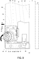
- the supporting portion 106 of the supporting member 84 is substantially lower than or as high as the carrying portion 40 of the second rail 30.
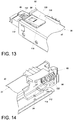
- An operator may rotate the height adjustment member 86 in a first operation direction A1 with respect to the coupling base 82 so that the second threaded structure 122 of the height adjustment member 86 works with the first threaded structure 110 of the supporting member 84 to displace the supporting member 84 with respect to the coupling base 82.
- the supporting portion 106 of the supporting member 84 will rise from its original position to another position, i.e., be adjusted in height with respect to the carrying portion 40 of the second rail 30, thanks to the first guiding feature 108 and/or the second guiding feature 116.
- the supporting member 84 When the operator rotates the height adjustment member 86 in the first operation direction A1, referring to FIG. 12 and FIG. 14 , the supporting member 84 is displaced in a first longitudinal direction L1 with respect to the coupling base 82 and/or the second rail 30. Once displaced a predetermined distance in the first longitudinal direction L1, the stop portion 112 of the supporting member 84 is blocked by the position-limiting section 114 of the coupling base 82 to prevent the supporting member 84 from excessive displacement in the first longitudinal direction L1.
- the operator may also rotate the height adjustment member 86 in a second operation direction (e.g., the opposite direction of the first operation direction A1), thereby displacing the supporting member 84 in a second longitudinal direction (e.g., the opposite direction of the first longitudinal direction L1) to lower the supporting portion 106 of the supporting member 84 with respect to the carrying portion 40 of the second rail 30.
- a second operation direction e.g., the opposite direction of the first operation direction A1
- a second longitudinal direction e.g., the opposite direction of the first longitudinal direction L1
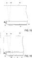
- the carrying portion 40 of the second rail 30 carries or supports the second furniture part 24a, and the supporting portion 106 of the supporting member 84 faces the second furniture part 24a.
- the height adjustment member 86 e.g., by rotating it in the first operation direction A1
- the supporting portion 106 of the supporting member 84 can be raised with respect to the carrying portion 40 of the second rail 30 by a height H by means of the first guiding feature 108 and/or the second guiding feature 116.
- the supporting member 84 can change the vertical distance H between the second furniture part 24a and the carrying portion 40 of the second rail 30 via the guiding feature 108 or 116, thereby adjusting the front-end height of the second furniture part 24a with respect to the first furniture part 22 in order to correct a front-end mounting error of the second furniture part 24a with respect to the first furniture part 22.
- the slide rail assembly 26 and/or the coupling mechanism 34 of the present invention preferably has the following features:
Landscapes
- Drawers Of Furniture (AREA)
Claims (10)
- Eine Gleitschienenmontage (26), umfassend:eine erste Schiene (28);eine zweite Schiene (30), die der Länge nach an der ersten Schiene (28) verschiebbar ist;
undeinen Kupplungsmechanismus (34), der neben der zweiten Schiene (30) angeordnet ist, wobei der Kupplungsmechanismus (34) aus den folgenden Komponenten besteht:einer ersten Basis (50); undeiner zweiten Basis (52), die beweglich an der ersten Basis (50) montiert ist;wobei der Kupplungsmechanismus (34) weiter aus einem Seitenverstellelement (54) besteht, mit dem die zweite Basis (52) an der zweiten Schiene (30) verstellt und dadurch seitlich verschoben wird;wobei die erste Basis (50) aus einer ersten Vorrichtung (62), die zweite Basis (52) aus einer zweiten Vorrichtung (64) besteht; eine der ersten Vorrichtungen (62) und der zweiten Vorrichtungen (64) mindestens einen Vorsprung (63a, 63b) aufweisen; die andere der ersten Vorrichtung (62) und der zweiten Vorrichtung (64) mindestens einen Aufnahmeraum (65a, 65b) aufweist, um in diesem den mindestens einen Vorsprung (63a, 63b) aufzunehmen; der mindestens eine Aufnahmeraum (65a, 65b) größer ist als der mindestens eine Vorsprung (63a, 63b), damit die zweite Basis (52) innerhalb eines begrenzten Bereichs an der ersten Basis (50) verschiebbar ist, da die erste Vorrichtung (62) mit der zweiten Vorrichtung (64) zusammenwirkt;dadurch gekennzeichnet, dassdie Gleitschienenmontage (26) weiter eine Kupplungsbasis (82) umfasst, die lösbar an der zweiten Schiene (30) befestigt und lösbar mit der ersten Basis (50) in Eingriff ist;wobei die Kupplungsbasis (82) aus einem elastischen Teil (90) besteht; die erste Basis (50) eine Einraststruktur (96) aufweist; der elastische Teil (90) der Kupplungsbasis (82) lösbar mit der Einraststruktur (96) der ersten Basis (50) in Eingriff ist und aus mindestens einem ersten Einrastteil (98) besteht; die Einraststruktur (96) mindestens aus einem zweiten Einrastteil (100) besteht, der mit dem ersten Einrastteil (98) in Übereinstimmung ist. - Die Gleitschienenmontage (26) nach Anspruch 1, wobei eine der ersten Basen (50) und der zweiten Basen (52) eine Führungsstruktur (70) aufweist, um die Verschiebung der zweiten Basis (52) an der ersten Basis (50) zu erleichtern.
- Die Gleitschienenmontage (26) nach einem der Ansprüche 1-2, wobei das Seitenverstellelement (54) drehbar an der zweiten Basis (52) montiert ist und und aus einem Einstellteil (78) besteht; die erste Basis (50) eine Übertragungsstruktur (80) aufweist, die mit dem Einstellteil (78) zusammenwirkt.
- Die Gleitschienenmontage (26) nach Anspruch 3, wobei der Einstellteil (78) im Wesentlichen eine spiralförmige Führungsrille ist; die Übertragungsstruktur (80) ein Vorsprung ist, der in der Führungsrille gebildet ist.
- Die Gleitschienenmontage (26) nach Anspruch 1, wobei der Kupplungsmechanismus (34) weiter aus einem Stützelement (84) und einem Höhenverstellglied (86) besteht; das Stützelement (84) aus einem Stützteil (106) besteht und mit dem Höhenverstellglied (86) das Stützelement (84) verstellt und dadurch an der Kupplungsbasis (82) verschoben wird, um mit der Führungsvorrichtung (108, 116) eine Höhe des Stützteils (106) des Stützelements (84) an der zweiten Schiene (30) zu verändern.
- Die Gleitschienenmontage (26) nach Anspruch 5, wobei die zweite Schiene (30) einen vorderen Teil (36a) und einen hinteren Teil (36b) aufweist; die Kupplungsbasis (82) in einer Position neben dem vorderen Teil (36a) der zweiten Schiene (30) an der zweiten Schiene (30) montiert ist; die Führungsvorrichtung (108, 116) eine geneigte Fläche und eine gebogene Fläche aufweist.
- Die Gleitschienenmontage (26) nach Anspruch 5, wobei das Höhenverstellglied (86) drehbar an der Kupplungsbasis (82) montiert ist; das Höhenverstellglied (86) und das Stützelement (84) entsprechende Längsgewinden (122, 110) aufweisen.
- Die Gleitschienenmontage (26) nach Anspruch 1, wobei die Kupplungsbasis (82) aus einem Dämpfungsteil (92) besteht; die erste Basis (50) aus einem Montageteil (60) besteht, der an eine erste Seitenwand (38a) der ersten Schiene (30) gedrückt wird; der Dämpfungsteil (92) an die zweite Basis (52) gedrückt werden kann, um einen möglichen Längsspalt (K) zwischen der ersten Basis (50) und der zweiten Schiene (30) durch eine Dämpfungsbewegung des Dämpfungsteils (92) auszugleichen.
- Die Gleitschienenmontage (26) nach einem der Ansprüche 1-8, wobei die Gleitschienenmontage (26) zum Montieren eines Möbelteils (24a) an einen Möbelbaukörper (22) konfiguriert ist, wobei dieser Möbelteil (24a) an diesem Möbelbaukörper (22) beweglich montiert ist; der Möbelteil (24a) mit dem Kupplungsmechanismus (34) lösbar mit der zweiten Schiene (30) der Gleitschienenmontage (26) montiert ist; die zweite Basis (52) am Möbelteil (24a) befestigt werden kann; die Seitenposition des Möbelteils (24a) am Möbelbaukörper (22) beim Verstellen der zweiten Basis (52) verändert und dadurch mit dem Seitenverstellelement (54) an der ersten Basis (50) verschoben wird.
- Die Gleitschienenmontage (26) nach Anspruch 9, wobei der Stützteil (106) des Stützelements (84) so ausgerichtet ist, dass dieser gegenüber dem Möbelteil (24a) angeordnet ist.
Applications Claiming Priority (1)
| Application Number | Priority Date | Filing Date | Title |
|---|---|---|---|
| TW106107479A TWI616163B (zh) | 2017-03-07 | 2017-03-07 | 用於傢俱部件的連接機構與滑軌總成 |
Publications (3)
| Publication Number | Publication Date |
|---|---|
| EP3372114A1 EP3372114A1 (de) | 2018-09-12 |
| EP3372114B1 EP3372114B1 (de) | 2019-03-20 |
| EP3372114B2 true EP3372114B2 (de) | 2021-12-15 |
Family
ID=60268301
Family Applications (1)
| Application Number | Title | Priority Date | Filing Date |
|---|---|---|---|
| EP17200267.7A Active EP3372114B2 (de) | 2017-03-07 | 2017-11-07 | Kopplungsmechanismus und gleitschienenanordnung für ein möbelteil |
Country Status (4)
| Country | Link |
|---|---|
| US (1) | US10470569B2 (de) |
| EP (1) | EP3372114B2 (de) |
| JP (1) | JP6770501B2 (de) |
| TW (1) | TWI616163B (de) |
Families Citing this family (7)
| Publication number | Priority date | Publication date | Assignee | Title |
|---|---|---|---|---|
| CN206640916U (zh) * | 2017-02-09 | 2017-11-14 | 索斯科公司 | 计算机机架系统和机架附接装置 |
| DE102018108647A1 (de) * | 2018-04-11 | 2019-10-17 | Paul Hettich Gmbh & Co. Kg | Auszugsführung und Schubkastenserie |
| IT201800007604A1 (it) * | 2018-07-30 | 2020-01-30 | Salice Arturo Spa | Guida di estrazione per cassetti provvista di un dispositivo per la regolazione in altezza del cassetto. |
| TWI693043B (zh) * | 2018-07-31 | 2020-05-11 | 川湖科技股份有限公司 | 調整機構 |
| TWI670031B (zh) * | 2018-09-27 | 2019-09-01 | 川湖科技股份有限公司 | 滑軌機構 |
| DE102019113107A1 (de) * | 2019-05-17 | 2020-11-19 | Paul Hettich Gmbh & Co. Kg | Schubkasten und Verfahren zur Montage eines Schubkastens |
| CN111616517A (zh) * | 2020-06-08 | 2020-09-04 | 郑州工程技术学院 | 一种酒店管理专用资料柜 |
Citations (3)
| Publication number | Priority date | Publication date | Assignee | Title |
|---|---|---|---|---|
| US9066587B1 (en) † | 2014-04-16 | 2015-06-30 | King Slide Works Co., Ltd. | Slide rail system and connecting device used for slide rail assembly |
| CN204467482U (zh) † | 2015-01-16 | 2015-07-15 | 北京世博金属制品有限公司 | 一种可拆卸可调节的抽屉前面板锁紧装置 |
| EP2929804B1 (de) † | 2014-04-09 | 2016-09-21 | King Slide Works Co., Ltd. | Verbindungsvorrichtung für eine Auszugsführung und Auszugsführungssystem |
Family Cites Families (24)
| Publication number | Priority date | Publication date | Assignee | Title |
|---|---|---|---|---|
| WO2004102032A2 (en) * | 2003-05-13 | 2004-11-25 | Grass America Inc. | Shock absorber and mounting system for a drawer slide |
| DE202006006065U1 (de) * | 2006-04-13 | 2007-08-23 | Alfit Ag | Unterflur-Führungsanordnung für Möbelteile, insbesondere im Korpus von Möbelstücken |
| TWI346532B (en) * | 2008-03-21 | 2011-08-11 | King Slide Works Co Ltd | Slide adjusting device for use in a drawer |
| AT506879B1 (de) * | 2008-06-10 | 2011-07-15 | Blum Gmbh Julius | Vorrichtung zum lösbaren kuppeln einer schublade mit einer schiene einer schubladenausziehführung |
| AT508265B1 (de) * | 2009-06-10 | 2013-05-15 | Blum Gmbh Julius | Ausziehführung für schubladen |
| DE202009017319U1 (de) * | 2009-12-21 | 2011-05-05 | Grass Gmbh | Möbel und Vorrichtung für ein Möbel |
| AT509414B1 (de) * | 2010-02-03 | 2013-04-15 | Blum Gmbh Julius | Kupplungsvorrichtung mit seitenverstellung für eine schublade |
| IT1403106B1 (it) * | 2010-12-15 | 2013-10-04 | Salice Arturo Spa | Dispositivo di aggancio di un cassetto ad una guida longitudinale |
| AT13205U1 (de) * | 2011-01-05 | 2013-08-15 | Blum Gmbh Julius | Kupplungsvorrichtung für Schubladen |
| AT510714B1 (de) * | 2011-01-05 | 2012-06-15 | Blum Gmbh Julius | Kupplungsvorrichtung für schubladen |
| AT511081B1 (de) * | 2011-05-05 | 2012-09-15 | Blum Gmbh Julius | Anordnung mit einer schublade und mit einer schubladenausziehführung |
| ITMI20111628A1 (it) * | 2011-09-08 | 2013-03-09 | Salice Arturo Spa | Dispositivo e metodo per il centraggio laterale di un cassetto o simile su una guida di estrazione e dispositivo di aggancio provvisto dello stesso |
| CN202269656U (zh) * | 2011-10-08 | 2012-06-13 | 广东泰明金属制品有限公司 | 抽屉滑轨的快装机构 |
| CN103653893B (zh) * | 2012-09-19 | 2016-02-10 | 李绍汉 | 抽屉位置调整装置 |
| US8979223B2 (en) * | 2012-12-12 | 2015-03-17 | Nan Juen International Co., Ltd. | Adjustable coupling device for connection between sliding rail assembly and a sliding box |
| US9101213B2 (en) * | 2013-11-22 | 2015-08-11 | Hardware Resources, Inc. | Undermount drawer slide position adjustment apparatus and method of use |
| AT515265B1 (de) * | 2014-01-09 | 2018-07-15 | Blum Gmbh Julius | Schubladenausziehführung |
| US8854769B1 (en) * | 2014-04-07 | 2014-10-07 | King Slide Works Co., Ltd. | Slide rail system and connecting device used for slide rail assembly |
| DE202014102893U1 (de) * | 2014-06-25 | 2015-10-05 | Grass Gmbh | Vorrichtung zur Anbringung einer Führungseinheit an einem Möbelteil |
| CN204181228U (zh) * | 2014-11-10 | 2015-03-04 | 广东泰明金属制品有限公司 | 抽屉滑轨的锁紧调节装置 |
| TWM495781U (zh) * | 2014-11-28 | 2015-02-21 | Sun Chain Trading Co Ltd | 隱藏式滑軌之前連接裝置 |
| US20160198855A1 (en) * | 2015-01-13 | 2016-07-14 | King Slide Works Co., Ltd. | Slide rail assembly and mounting device thereof |
| TWI548370B (zh) * | 2015-11-12 | 2016-09-11 | 川湖科技股份有限公司 | 快拆式滑軌組件 |
| DE202015107020U1 (de) * | 2015-12-22 | 2017-03-24 | Grass Gmbh | Verstellvorrichtung, Führungseinheit und Möbel |
-
2017
- 2017-03-07 TW TW106107479A patent/TWI616163B/zh active
- 2017-10-27 US US15/795,787 patent/US10470569B2/en active Active
- 2017-11-07 EP EP17200267.7A patent/EP3372114B2/de active Active
- 2017-11-16 JP JP2017220808A patent/JP6770501B2/ja active Active
Patent Citations (3)
| Publication number | Priority date | Publication date | Assignee | Title |
|---|---|---|---|---|
| EP2929804B1 (de) † | 2014-04-09 | 2016-09-21 | King Slide Works Co., Ltd. | Verbindungsvorrichtung für eine Auszugsführung und Auszugsführungssystem |
| US9066587B1 (en) † | 2014-04-16 | 2015-06-30 | King Slide Works Co., Ltd. | Slide rail system and connecting device used for slide rail assembly |
| CN204467482U (zh) † | 2015-01-16 | 2015-07-15 | 北京世博金属制品有限公司 | 一种可拆卸可调节的抽屉前面板锁紧装置 |
Also Published As
| Publication number | Publication date |
|---|---|
| US10470569B2 (en) | 2019-11-12 |
| EP3372114A1 (de) | 2018-09-12 |
| EP3372114B1 (de) | 2019-03-20 |
| TW201832691A (zh) | 2018-09-16 |
| US20180255926A1 (en) | 2018-09-13 |
| JP6770501B2 (ja) | 2020-10-14 |
| JP2018143750A (ja) | 2018-09-20 |
| TWI616163B (zh) | 2018-03-01 |
Similar Documents
| Publication | Publication Date | Title |
|---|---|---|
| EP3372114B2 (de) | Kopplungsmechanismus und gleitschienenanordnung für ein möbelteil | |
| EP3372117B1 (de) | Kopplungsmechanismus und gleitschienenanordnung mit dämpfungsfunktion | |
| EP3372115B1 (de) | Kopplungsmechanismus und gleitschienenanordnung für möbelteil | |
| US7883162B2 (en) | Device for influencing the movement of furniture parts which can be moved with respect to one another, and piece of furniture | |
| EP3167760B1 (de) | Montagemechanismus | |
| EP3603450B1 (de) | Justiermechanismus für gleitschiene | |
| EP3167755B1 (de) | Schubladenauszugsanordnung | |
| EP3613310B1 (de) | Anpassungsmechanismus für gleitschienenanordnung | |
| CN108567252B (zh) | 用于家具部件的连接机构与滑轨总成 | |
| CN108567253B (zh) | 用于家具部件的连接机构与滑轨总成 | |
| KR102314062B1 (ko) | 서랍용 언더레일 가이드 브라켓 | |
| US9237804B1 (en) | Drawer slide rail assembly | |
| EP2965658B1 (de) | Gleitschienenanordnung für Schublade | |
| CN108567254B (zh) | 具有缓冲功能的连接机构与滑轨总成 | |
| EP3449767B1 (de) | Vorrichtung für die verstellbare halterung von ausziehführungen an schubladen | |
| US20220079337A1 (en) | Height adjustment system for sliding drawers |
Legal Events
| Date | Code | Title | Description |
|---|---|---|---|
| PUAI | Public reference made under article 153(3) epc to a published international application that has entered the european phase |
Free format text: ORIGINAL CODE: 0009012 |
|
| STAA | Information on the status of an ep patent application or granted ep patent |
Free format text: STATUS: REQUEST FOR EXAMINATION WAS MADE |
|
| 17P | Request for examination filed |
Effective date: 20180608 |
|
| AK | Designated contracting states |
Kind code of ref document: A1 Designated state(s): AL AT BE BG CH CY CZ DE DK EE ES FI FR GB GR HR HU IE IS IT LI LT LU LV MC MK MT NL NO PL PT RO RS SE SI SK SM TR |
|
| AX | Request for extension of the european patent |
Extension state: BA ME |
|
| GRAP | Despatch of communication of intention to grant a patent |
Free format text: ORIGINAL CODE: EPIDOSNIGR1 |
|
| STAA | Information on the status of an ep patent application or granted ep patent |
Free format text: STATUS: GRANT OF PATENT IS INTENDED |
|
| INTG | Intention to grant announced |
Effective date: 20181016 |
|
| RIN1 | Information on inventor provided before grant (corrected) |
Inventor name: HUANG, CI-BIN Inventor name: SU, FANG-CHENG Inventor name: HUANG, SHIH-LUNG Inventor name: CHEN, KEN-CHING Inventor name: WANG, CHUN-CHIANG |
|
| GRAS | Grant fee paid |
Free format text: ORIGINAL CODE: EPIDOSNIGR3 |
|
| GRAA | (expected) grant |
Free format text: ORIGINAL CODE: 0009210 |
|
| STAA | Information on the status of an ep patent application or granted ep patent |
Free format text: STATUS: THE PATENT HAS BEEN GRANTED |
|
| AK | Designated contracting states |
Kind code of ref document: B1 Designated state(s): AL AT BE BG CH CY CZ DE DK EE ES FI FR GB GR HR HU IE IS IT LI LT LU LV MC MK MT NL NO PL PT RO RS SE SI SK SM TR |
|
| REG | Reference to a national code |
Ref country code: GB Ref legal event code: FG4D |
|
| REG | Reference to a national code |
Ref country code: CH Ref legal event code: EP |
|
| REG | Reference to a national code |
Ref country code: DE Ref legal event code: R096 Ref document number: 602017002830 Country of ref document: DE |
|
| REG | Reference to a national code |
Ref country code: AT Ref legal event code: REF Ref document number: 1109590 Country of ref document: AT Kind code of ref document: T Effective date: 20190415 |
|
| REG | Reference to a national code |
Ref country code: IE Ref legal event code: FG4D |
|
| REG | Reference to a national code |
Ref country code: NL Ref legal event code: MP Effective date: 20190320 |
|
| PG25 | Lapsed in a contracting state [announced via postgrant information from national office to epo] |
Ref country code: LT Free format text: LAPSE BECAUSE OF FAILURE TO SUBMIT A TRANSLATION OF THE DESCRIPTION OR TO PAY THE FEE WITHIN THE PRESCRIBED TIME-LIMIT Effective date: 20190320 Ref country code: NO Free format text: LAPSE BECAUSE OF FAILURE TO SUBMIT A TRANSLATION OF THE DESCRIPTION OR TO PAY THE FEE WITHIN THE PRESCRIBED TIME-LIMIT Effective date: 20190620 Ref country code: SE Free format text: LAPSE BECAUSE OF FAILURE TO SUBMIT A TRANSLATION OF THE DESCRIPTION OR TO PAY THE FEE WITHIN THE PRESCRIBED TIME-LIMIT Effective date: 20190320 Ref country code: FI Free format text: LAPSE BECAUSE OF FAILURE TO SUBMIT A TRANSLATION OF THE DESCRIPTION OR TO PAY THE FEE WITHIN THE PRESCRIBED TIME-LIMIT Effective date: 20190320 |
|
| REG | Reference to a national code |
Ref country code: LT Ref legal event code: MG4D |
|
| PG25 | Lapsed in a contracting state [announced via postgrant information from national office to epo] |
Ref country code: NL Free format text: LAPSE BECAUSE OF FAILURE TO SUBMIT A TRANSLATION OF THE DESCRIPTION OR TO PAY THE FEE WITHIN THE PRESCRIBED TIME-LIMIT Effective date: 20190320 Ref country code: HR Free format text: LAPSE BECAUSE OF FAILURE TO SUBMIT A TRANSLATION OF THE DESCRIPTION OR TO PAY THE FEE WITHIN THE PRESCRIBED TIME-LIMIT Effective date: 20190320 Ref country code: GR Free format text: LAPSE BECAUSE OF FAILURE TO SUBMIT A TRANSLATION OF THE DESCRIPTION OR TO PAY THE FEE WITHIN THE PRESCRIBED TIME-LIMIT Effective date: 20190621 Ref country code: LV Free format text: LAPSE BECAUSE OF FAILURE TO SUBMIT A TRANSLATION OF THE DESCRIPTION OR TO PAY THE FEE WITHIN THE PRESCRIBED TIME-LIMIT Effective date: 20190320 Ref country code: BG Free format text: LAPSE BECAUSE OF FAILURE TO SUBMIT A TRANSLATION OF THE DESCRIPTION OR TO PAY THE FEE WITHIN THE PRESCRIBED TIME-LIMIT Effective date: 20190620 Ref country code: RS Free format text: LAPSE BECAUSE OF FAILURE TO SUBMIT A TRANSLATION OF THE DESCRIPTION OR TO PAY THE FEE WITHIN THE PRESCRIBED TIME-LIMIT Effective date: 20190320 |
|
| REG | Reference to a national code |
Ref country code: AT Ref legal event code: MK05 Ref document number: 1109590 Country of ref document: AT Kind code of ref document: T Effective date: 20190320 |
|
| PG25 | Lapsed in a contracting state [announced via postgrant information from national office to epo] |
Ref country code: ES Free format text: LAPSE BECAUSE OF FAILURE TO SUBMIT A TRANSLATION OF THE DESCRIPTION OR TO PAY THE FEE WITHIN THE PRESCRIBED TIME-LIMIT Effective date: 20190320 Ref country code: PT Free format text: LAPSE BECAUSE OF FAILURE TO SUBMIT A TRANSLATION OF THE DESCRIPTION OR TO PAY THE FEE WITHIN THE PRESCRIBED TIME-LIMIT Effective date: 20190720 Ref country code: AL Free format text: LAPSE BECAUSE OF FAILURE TO SUBMIT A TRANSLATION OF THE DESCRIPTION OR TO PAY THE FEE WITHIN THE PRESCRIBED TIME-LIMIT Effective date: 20190320 Ref country code: IT Free format text: LAPSE BECAUSE OF FAILURE TO SUBMIT A TRANSLATION OF THE DESCRIPTION OR TO PAY THE FEE WITHIN THE PRESCRIBED TIME-LIMIT Effective date: 20190320 Ref country code: EE Free format text: LAPSE BECAUSE OF FAILURE TO SUBMIT A TRANSLATION OF THE DESCRIPTION OR TO PAY THE FEE WITHIN THE PRESCRIBED TIME-LIMIT Effective date: 20190320 Ref country code: SK Free format text: LAPSE BECAUSE OF FAILURE TO SUBMIT A TRANSLATION OF THE DESCRIPTION OR TO PAY THE FEE WITHIN THE PRESCRIBED TIME-LIMIT Effective date: 20190320 Ref country code: RO Free format text: LAPSE BECAUSE OF FAILURE TO SUBMIT A TRANSLATION OF THE DESCRIPTION OR TO PAY THE FEE WITHIN THE PRESCRIBED TIME-LIMIT Effective date: 20190320 Ref country code: CZ Free format text: LAPSE BECAUSE OF FAILURE TO SUBMIT A TRANSLATION OF THE DESCRIPTION OR TO PAY THE FEE WITHIN THE PRESCRIBED TIME-LIMIT Effective date: 20190320 |
|
| PG25 | Lapsed in a contracting state [announced via postgrant information from national office to epo] |
Ref country code: SM Free format text: LAPSE BECAUSE OF FAILURE TO SUBMIT A TRANSLATION OF THE DESCRIPTION OR TO PAY THE FEE WITHIN THE PRESCRIBED TIME-LIMIT Effective date: 20190320 Ref country code: PL Free format text: LAPSE BECAUSE OF FAILURE TO SUBMIT A TRANSLATION OF THE DESCRIPTION OR TO PAY THE FEE WITHIN THE PRESCRIBED TIME-LIMIT Effective date: 20190320 |
|
| REG | Reference to a national code |
Ref country code: DE Ref legal event code: R026 Ref document number: 602017002830 Country of ref document: DE |
|
| PLBI | Opposition filed |
Free format text: ORIGINAL CODE: 0009260 |
|
| PG25 | Lapsed in a contracting state [announced via postgrant information from national office to epo] |
Ref country code: AT Free format text: LAPSE BECAUSE OF FAILURE TO SUBMIT A TRANSLATION OF THE DESCRIPTION OR TO PAY THE FEE WITHIN THE PRESCRIBED TIME-LIMIT Effective date: 20190320 Ref country code: IS Free format text: LAPSE BECAUSE OF FAILURE TO SUBMIT A TRANSLATION OF THE DESCRIPTION OR TO PAY THE FEE WITHIN THE PRESCRIBED TIME-LIMIT Effective date: 20190720 |
|
| PLAX | Notice of opposition and request to file observation + time limit sent |
Free format text: ORIGINAL CODE: EPIDOSNOBS2 |
|
| 26 | Opposition filed |
Opponent name: PAUL HETTICH GMBH & CO. KG Effective date: 20191218 |
|
| PG25 | Lapsed in a contracting state [announced via postgrant information from national office to epo] |
Ref country code: DK Free format text: LAPSE BECAUSE OF FAILURE TO SUBMIT A TRANSLATION OF THE DESCRIPTION OR TO PAY THE FEE WITHIN THE PRESCRIBED TIME-LIMIT Effective date: 20190320 |
|
| PG25 | Lapsed in a contracting state [announced via postgrant information from national office to epo] |
Ref country code: TR Free format text: LAPSE BECAUSE OF FAILURE TO SUBMIT A TRANSLATION OF THE DESCRIPTION OR TO PAY THE FEE WITHIN THE PRESCRIBED TIME-LIMIT Effective date: 20190320 |
|
| PLBB | Reply of patent proprietor to notice(s) of opposition received |
Free format text: ORIGINAL CODE: EPIDOSNOBS3 |
|
| PG25 | Lapsed in a contracting state [announced via postgrant information from national office to epo] |
Ref country code: MC Free format text: LAPSE BECAUSE OF FAILURE TO SUBMIT A TRANSLATION OF THE DESCRIPTION OR TO PAY THE FEE WITHIN THE PRESCRIBED TIME-LIMIT Effective date: 20190320 Ref country code: LU Free format text: LAPSE BECAUSE OF NON-PAYMENT OF DUE FEES Effective date: 20191107 |
|
| REG | Reference to a national code |
Ref country code: BE Ref legal event code: MM Effective date: 20191130 |
|
| PG25 | Lapsed in a contracting state [announced via postgrant information from national office to epo] |
Ref country code: FR Free format text: LAPSE BECAUSE OF NON-PAYMENT OF DUE FEES Effective date: 20191130 |
|
| PG25 | Lapsed in a contracting state [announced via postgrant information from national office to epo] |
Ref country code: BE Free format text: LAPSE BECAUSE OF NON-PAYMENT OF DUE FEES Effective date: 20191130 |
|
| PG25 | Lapsed in a contracting state [announced via postgrant information from national office to epo] |
Ref country code: CY Free format text: LAPSE BECAUSE OF FAILURE TO SUBMIT A TRANSLATION OF THE DESCRIPTION OR TO PAY THE FEE WITHIN THE PRESCRIBED TIME-LIMIT Effective date: 20190320 |
|
| PG25 | Lapsed in a contracting state [announced via postgrant information from national office to epo] |
Ref country code: LI Free format text: LAPSE BECAUSE OF FAILURE TO SUBMIT A TRANSLATION OF THE DESCRIPTION OR TO PAY THE FEE WITHIN THE PRESCRIBED TIME-LIMIT Effective date: 20201130 Ref country code: CH Free format text: LAPSE BECAUSE OF FAILURE TO SUBMIT A TRANSLATION OF THE DESCRIPTION OR TO PAY THE FEE WITHIN THE PRESCRIBED TIME-LIMIT Effective date: 20201130 |
|
| REG | Reference to a national code |
Ref country code: CH Ref legal event code: PL |
|
| PG25 | Lapsed in a contracting state [announced via postgrant information from national office to epo] |
Ref country code: HU Free format text: LAPSE BECAUSE OF FAILURE TO SUBMIT A TRANSLATION OF THE DESCRIPTION OR TO PAY THE FEE WITHIN THE PRESCRIBED TIME-LIMIT; INVALID AB INITIO Effective date: 20171107 Ref country code: MT Free format text: LAPSE BECAUSE OF FAILURE TO SUBMIT A TRANSLATION OF THE DESCRIPTION OR TO PAY THE FEE WITHIN THE PRESCRIBED TIME-LIMIT Effective date: 20190320 |
|
| PG25 | Lapsed in a contracting state [announced via postgrant information from national office to epo] |
Ref country code: SI Free format text: LAPSE BECAUSE OF FAILURE TO SUBMIT A TRANSLATION OF THE DESCRIPTION OR TO PAY THE FEE WITHIN THE PRESCRIBED TIME-LIMIT Effective date: 20190320 |
|
| PUAH | Patent maintained in amended form |
Free format text: ORIGINAL CODE: 0009272 |
|
| STAA | Information on the status of an ep patent application or granted ep patent |
Free format text: STATUS: PATENT MAINTAINED AS AMENDED |
|
| 27A | Patent maintained in amended form |
Effective date: 20211215 |
|
| AK | Designated contracting states |
Kind code of ref document: B2 Designated state(s): AL AT BE BG CH CY CZ DE DK EE ES FI FR GB GR HR HU IE IS IT LI LT LU LV MC MK MT NL NO PL PT RO RS SE SI SK SM TR |
|
| REG | Reference to a national code |
Ref country code: DE Ref legal event code: R102 Ref document number: 602017002830 Country of ref document: DE |
|
| PG25 | Lapsed in a contracting state [announced via postgrant information from national office to epo] |
Ref country code: MK Free format text: LAPSE BECAUSE OF FAILURE TO SUBMIT A TRANSLATION OF THE DESCRIPTION OR TO PAY THE FEE WITHIN THE PRESCRIBED TIME-LIMIT Effective date: 20190320 |
|
| PGFP | Annual fee paid to national office [announced via postgrant information from national office to epo] |
Ref country code: GB Payment date: 20250909 Year of fee payment: 9 |
|
| PGFP | Annual fee paid to national office [announced via postgrant information from national office to epo] |
Ref country code: IE Payment date: 20250909 Year of fee payment: 9 |
|
| PGFP | Annual fee paid to national office [announced via postgrant information from national office to epo] |
Ref country code: DE Payment date: 20250910 Year of fee payment: 9 |