EP3603450B1 - Justiermechanismus für gleitschiene - Google Patents
Justiermechanismus für gleitschiene Download PDFInfo
- Publication number
- EP3603450B1 EP3603450B1 EP19150047.9A EP19150047A EP3603450B1 EP 3603450 B1 EP3603450 B1 EP 3603450B1 EP 19150047 A EP19150047 A EP 19150047A EP 3603450 B1 EP3603450 B1 EP 3603450B1
- Authority
- EP
- European Patent Office
- Prior art keywords
- component
- feature
- adjusting element
- adjustment mechanism
- transverse
- Prior art date
- Legal status (The legal status is an assumption and is not a legal conclusion. Google has not performed a legal analysis and makes no representation as to the accuracy of the status listed.)
- Active
Links
Images


Classifications
-
- A—HUMAN NECESSITIES
- A47—FURNITURE; DOMESTIC ARTICLES OR APPLIANCES; COFFEE MILLS; SPICE MILLS; SUCTION CLEANERS IN GENERAL
- A47B—TABLES; DESKS; OFFICE FURNITURE; CABINETS; DRAWERS; GENERAL DETAILS OF FURNITURE
- A47B88/00—Drawers for tables, cabinets or like furniture; Guides for drawers
- A47B88/40—Sliding drawers; Slides or guides therefor
- A47B88/407—Adjustably or detachably mounted drawers
-
- A—HUMAN NECESSITIES
- A47—FURNITURE; DOMESTIC ARTICLES OR APPLIANCES; COFFEE MILLS; SPICE MILLS; SUCTION CLEANERS IN GENERAL
- A47B—TABLES; DESKS; OFFICE FURNITURE; CABINETS; DRAWERS; GENERAL DETAILS OF FURNITURE
- A47B88/00—Drawers for tables, cabinets or like furniture; Guides for drawers
- A47B88/40—Sliding drawers; Slides or guides therefor
- A47B88/423—Fastening devices for slides or guides
- A47B88/427—Fastening devices for slides or guides at drawer side
- A47B2088/4276—Fastening devices for slides or guides at drawer side at drawer front via latch means or locking lever
-
- A—HUMAN NECESSITIES
- A47—FURNITURE; DOMESTIC ARTICLES OR APPLIANCES; COFFEE MILLS; SPICE MILLS; SUCTION CLEANERS IN GENERAL
- A47B—TABLES; DESKS; OFFICE FURNITURE; CABINETS; DRAWERS; GENERAL DETAILS OF FURNITURE
- A47B88/00—Drawers for tables, cabinets or like furniture; Guides for drawers
- A47B88/40—Sliding drawers; Slides or guides therefor
- A47B88/423—Fastening devices for slides or guides
- A47B88/427—Fastening devices for slides or guides at drawer side
- A47B2088/4278—Quick-release clip
Definitions
- the present invention relates to an adjustment mechanism and more particularly to an adjustment mechanism that enables longitudinal adjustment.
- an undermount drawer slide rail assembly is mounted on a bottom portion of a drawer and is therefore hidden from view.
- a slide rail assembly typically includes a first rail and a second rail that can be displaced with respect to the first rail, wherein the first rail is mounted on the body of a cabinet while the second rail serves to carry or support a drawer so that the drawer can be easily pulled out of and pushed back into the cabinet body via the second rail with respect to the first rail.
- the undermount drawer slide rail assembly stays hidden at the bottom of the drawer.
- US Patent No. 9,060,604 B2 discloses a device (10) for laterally centering a drawer.
- the device (10) includes a first coupling part (26) and a second coupling part (27), which are respectively connected to a hooking device (12) of a drawer (13) and a pull-out guide (11).
- the first coupling part (26) and the second coupling part (27) are conformed with elastically yieldable means in a lateral direction in order to cause a forced engagement and/or a shaped engagement between the first coupling part (26) and the second coupling part (27), thereby compensating for any lateral play between the hooking device (12) and the pull-out guide (11).
- WO 2012/079793 A1 discloses an adjustment mechanism, comprising: a first adjustment device including: a first component; a second component; a first adjusting element disposed on the first component; and a first structure disposed on the second component; that the first adjusting element and the first structure include a first feature and a second feature respectively, and the first feature and the second feature correspond to each other; and that when the first adjusting element is operated, the first feature and the second feature work with each other to longitudinally displace, and thereby adjust, the second component and the first component with respect to each other.
- US 2014/0175965 A1 discloses an adjustment mechanism comprising a first body part, a second body part and a first coupling part.
- the second body part is slidably connected to the first part of body and adjustable with respect thereto in a longitudinal direction by a longitudinal adjusting means, comprising a longitudinal screw connected to the second body part and a nut rotatably supported but not axially displaceable from the first body part.
- the first coupling part is connectable to the second body part by a lateral adjustment means, comprising a threaded pin integral with the coupling part and a drive female thread rotatably supported but not axially movable by the second body part.
- the present invention relates to an adjustment mechanism that enables longitudinal and transversal adjustment.
- an adjustment mechanism includes a first adjustment device, and the first adjustment device includes a first component, a second component, a first adjusting element, and a first structure.
- the first adjusting element is disposed on the first component while the first structure is disposed on the second component.
- the first adjusting element and the first structure include a first feature and a second feature respectively, wherein the first and the second features correspond to each other.
- first feature of the first adjusting element and the second feature of the first structure are screw threads that are threadedly engaged with each other.
- the first component includes a pair of walls, and the pair of walls define a space therebetween for accommodating the first adjusting element.
- the second component includes a mounting portion for supporting the first structure, and the first structure has a first abutting portion and a second abutting portion that are located on two opposite sides of the mounting portion respectively.
- the first adjusting element is slightly smaller than the space and can therefore be operated by rotation about the axis defined by the first structure, and the pair of walls prevent the first adjusting element from being longitudinally displaced.
- first and the second components include a first longitudinal guiding feature and a second longitudinal guiding feature respectively.
- the first and the second longitudinal guiding features are configured to work with each other, and one of the first and the second longitudinal guiding features is larger than the other of the first and the second longitudinal guiding features.
- the first longitudinal guiding feature is a recess or a hole
- the second longitudinal guiding feature is a protruding portion
- the second component has a longitudinal opening
- the adjustment mechanism further includes a first connecting member.
- the first connecting member includes a head and a body, wherein the head is larger than the body.
- the body of the first connecting member extends through a portion of the longitudinal opening and is connected to the first component, with the head of the first connecting member stopped on one side of the second component.
- the adjustment mechanism further includes a second adjustment device, and the second adjustment device includes a third component, a second adjusting element, and a second structure.
- the second adjusting element is disposed on the second component while the second structure is disposed on the third component.
- the second adjusting element includes an adjusting portion. When the second adjusting element is operated, the adjusting portion and the second structure work with each other to transversely displace, and thereby adjust, the second component and the third component with respect to each other.
- the second and the third components include a first transverse guiding feature and a second transverse guiding feature respectively.
- the first and the second transverse guiding features are configured to work with each other, and one of the first and the second transverse guiding features is larger than the other of the first and the second transverse guiding features.
- the second component includes at least one guiding structure for keeping at least one corresponding edge portion of the third component in place.
- the third component has a first space larger than the head of the first connecting member.
- the adjustment mechanism further includes a second connecting member, and the third component includes a transverse opening.
- the second connecting member includes a head and a body, wherein the head is larger than the body.
- the body of the second connecting member extends through a portion of the transverse opening of the third component and is connected to the second component, with the head of the second connecting member stopped on one side of the third component.
- the first component has a second space larger than the body of the second connecting member.
- the third component includes a connecting portion for connecting the third component to a target object.
- the third component further includes a flexible arm, and the flexible arm has a plurality of engaging sections for engaging with the target object.
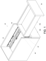
- a piece of furniture 20 includes a first furniture part 22 and at least one second furniture part.
- two second furniture parts 24a, 24b are shown by way of example.
- Each of the second furniture parts, such as the second furniture part 24a can be displaced with respect to the first furniture part 22.
- the second furniture part 24a can be easily displaced with respect to the first furniture part 22 via a pair of slide rail assemblies 26.
- the first furniture part 22 may be the body of a furniture cabinet, and the two second furniture parts 24a, 24b may be drawers; the present invention has no limitation in this regard.
- the second furniture part 24a is mounted on the first furniture part 22 through the pair of slide rail assemblies 26 in a movable manner.
- each slide rail assembly 26 is mounted on a bottom portion of the second furniture part 24a to form a so-called undermount slide rail assembly. More specifically, each slide rail assembly 26 includes a first rail 28, a second rail 30 (referred to in the claims as a slide rail) longitudinally displaceable with respect to the first rail 28, and preferably also a third rail 32 movably mounted between the first rail 28 and the second rail 30 to increase the distance for which the second rail 30 can be displaced with respect to the first rail 28.
- the first rails 28 are fixedly mounted on the first furniture part 22.
- the second rails 30 are configured to carry the second furniture part 24a (referred to in the claims as an object) so that the second furniture part 24a can be easily displaced via the second rails 30 from inside the first furniture part 22 to a position outside the first furniture part 22 and vice versa.
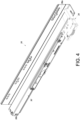
- the slide rail assembly 26 includes an adjustment mechanism 34 adjacent to the second rail 30.
- the second rail 30 has a front portion 36a and a rear portion 36b, and the adjustment mechanism 34 is mounted adjacent to the front portion 36a of the second rail 30 by way of example.
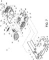
- the adjustment mechanism 34 includes a first component 42, a second component 44, a first adjusting element 46, and a first structure 48.
- the first component 42, the second component 44, the first adjusting element 46, and the first structure 48 constitute a first adjustment device.
- the adjustment mechanism 34 further includes a third component 50, a second adjusting element 52, and a second structure 54.
- the second component 44, the third component 50, the second adjusting element 52, and the second structure 54 constitute a second adjustment device.
- the first adjusting element 46 is arranged on one of the first component 42 and the second component 44.
- the first adjusting element 46 is arranged on the first component 42 by way of example but not limitation.
- the first structure 48 is arranged on the other of the first component 42 and the second component 44.
- the first structure 48 is arranged on the second component 44 by way of example but not limitation.
- the first adjusting element 46 and the first structure 48 include a first feature 56 and a second feature 58 respectively, wherein the first feature 56 and the second feature 58 correspond to each other.
- the first feature 56 of the first adjusting element 46 and the second feature 58 of the first structure 48 are screw threads that are threadedly engaged with each other.
- the first adjusting element 46 is a turning wheel
- the first feature 56 of the first adjusting element 46 is an internal thread
- the first structure 48 is a rod
- the second feature 58 of the first structure 48 is an external thread.
- the first structure 48 is substantially longitudinally disposed with respect to the second component 44, and the first adjusting element 46 can be operated by being rotated about an axis defined by the first structure 48.
- the first component 42 includes a pair of walls, such as a first wall 60a and a second wall 60b.
- the pair of walls 60a, 60b define a space 62 therebetween, and the space 62 is used to accommodate the first adjusting element 46.
- the first adjusting element 46 is slightly smaller than the space 62 so as to be rotatable about the axis defined by the first structure 48 when operated.
- the pair of walls 60a, 60b can also prevent the first adjusting element 46 from longitudinal displacement.
- the pair of walls 60a, 60b are configured to abut against the first adjusting element 46 so that the first adjusting element 46 cannot be longitudinally moved.
- the second component 44 includes a mounting portion 64 for supporting the first structure 48.
- the second component 44 further includes a mounting wall 66.
- the first structure 48 has a first end portion E1 and a second end portion E2, with the second feature 58 lying between the first end portion E1 and the second end portion E2.
- the first end portion E1 of the first structure 48 is disposed on the mounting portion 64; the second end portion E2 of the first structure 48 extends through the mounting wall 66.
- the first structure 48 has a first abutting portion 66a and a second abutting portion 66b (see FIG. 5 ) that correspond to, or are configured to abut against, two opposite sides of the mounting portion 64 respectively.
- the first component 42 and the second component 44 include a first longitudinal guiding feature 70 and a second longitudinal guiding feature 72 respectively, wherein the first longitudinal guiding feature 70 and the second longitudinal guiding feature 72 are configured to work with each other, and wherein one of the first longitudinal guiding feature 70 and the second longitudinal guiding feature 72 is larger than the other of the first longitudinal guiding feature 70 and the second longitudinal guiding feature 72.
- the first longitudinal guiding feature 70 has a greater longitudinal length than the second longitudinal guiding feature 72 by way of example but not limitation.
- the first longitudinal guiding feature 70 is a recess or a hole while the second longitudinal guiding feature 72 is a protruding portion.
- the first longitudinal guiding feature 70 and the second longitudinal guiding feature 72 allow the first component 42 and the second component 44 to be longitudinally displaced with respect to each other to a limited extent.
- first longitudinal guiding features 70 and a plurality of second longitudinal guiding features 72 that correspond to and are configured to work with one another; in practice, there is no limitation on the number of the first and the second longitudinal guiding features 70, 72.
- the second component 44 includes a longitudinal opening 74
- the adjustment mechanism 34 further includes a first connecting member 76.
- the first connecting member 76 includes a head 76a and a body 76b, wherein the head 76a is larger than the body 76b.
- the body 76b of the first connecting member 76 passes through a portion of the longitudinal opening 74 to connect with the first component 42, with the head 76a of the first connecting member 76 stopped on one side of the second component 44.
- the second adjusting element 52 is arranged on one of the second component 44 and the third component 50.
- the second adjusting element 52 is arranged on the second component 44 by way of example but not limitation.
- the second adjusting element 52 includes an adjusting portion 53.
- the second structure 54 is arranged on the other of the second component 44 and the third component 50.
- the second structure 54 is arranged on the third component 50 by way of example but not limitation.
- the second adjusting element 52 is a turning wheel.
- the second adjusting element 52 is mounted on a shaft portion 78 of the second component 44 and can be operated by being rotated about an axis defined by the shaft portion 78.
- the second structure 54 is a projection
- the adjusting portion 53 of the second adjusting element 52 is a generally spiral guide groove
- the second structure 54 is in the guide groove (see FIG. 8 ).
- the axis of the first adjusting element 46 is perpendicular to that of the second adjusting element 52; that is to say, the direction along which the first structure 48 is disposed is perpendicular to the direction along which the shaft portion 78 is disposed.
- the second component 44 and the third component 50 include a first transverse guiding feature 80 and a second transverse guiding feature 82 respectively, wherein the first transverse guiding features 80 and the second transverse guiding feature 82 are configured to work with each other, and wherein one of the first transverse guiding feature 80 and the second transverse guiding feature 82 is large than the other of the first transverse guiding feature 80 and the second transverse guiding feature 82.
- the first transverse guiding feature 80 has a greater transverse length than the second transverse guiding feature 82 by way of example but not limitation.
- the first transverse guiding feature 80 is a recess or a hole while the second transverse guiding feature 82 is a protruding portion.
- the first transverse guiding feature 80 and the second transverse guiding feature 82 allow the second component 44 and the third component 50 to be transversely displaced with respect to each other to a limited extent.
- the second component 44 includes at least one guiding structure 84 for keeping at least one corresponding edge portion 51 of the third component 50 in position (see FIG. 5 or FIG. 7 ).
- the second component 44 includes two guiding structures 84 by way of example, and each guiding structure 84 has a hook-shape guiding block against which the corresponding edge portion 51 of the third component 50 can abut to help guide the second component 44 and the third component 50 in the correct directions while the two components 44, 50 are being displaced with respect to each other.
- the third component 50 has a first space H1 larger than the head 76a of the first connecting member 76 (see FIG. 5 ).
- the first space H1 may be, but is not limited to, a through hole or a groove.
- the third component 50 includes a transverse opening 86
- the adjustment mechanism 34 further includes a second connecting member 88.
- the second connecting member 88 includes a head 88a and a body 88b, wherein the head 88a is larger than the body 88b.
- the body 88b of the second connecting member 88 passes through a portion of the transverse opening 86 of the third component 50 and is connected to and passes through the second component 44, with the head 88a of the second connecting member 88 stopped on one side of the third component 50.
- the first component 42 has a second space H2 larger than the body 88b of the second connecting member 88 (see FIG. 6 ).
- the third component 50 includes a connecting portion 90 and a flexible arm 92.
- the connecting portion 90 is configured to connect the third component 50 to a target object (e.g., a slide rail).
- the flexible arm 92 has a plurality of engaging sections 92a for engaging with the target object.
- the adjustment mechanism 34 is mounted on the second rail 30.
- the adjustment mechanism 34 is connected to the second rail 30 in a detachable manner.
- the connecting portion 90 of the third component 50 is a fastening hook configured to hook, and thus be fastened, to a first corresponding part 94 (e.g., a wall section) of the second rail 30.
- the flexible arm 92 of the third component 50 can engage with a second corresponding part 96 of the second rail 30 via the engaging sections 92a.
- the engaging sections 92a and the second corresponding part 96 have corresponding serrated contours.
- the first component 42 is configured to connect with the second furniture part 24a via at least one connecting feature 91 (e.g., threadedly).
- the second furniture part 24a can be moved via the second rail 30 to enter an opened or retracted state with respect to the first furniture part 22.
- the second furniture part 24a is in the retracted state by way of example.
- a first longitudinal distance L1 exists between a front portion 93 (e.g., a front panel) of the second furniture part 24a and a front edge 95 of the first furniture part 22 before the first adjusting element 46 is operated
- a first transverse distance T1 exists between a lateral portion of the second furniture part 24a and a lateral portion of the first furniture part 22 before the second adjusting element 52 is operated.
- the first component 42 and the second component 44 have a first scale feature M1 and a first indicator feature K1 respectively, wherein the first scale feature M1 and the first indicator feature K1 are configured to work with each other.
- the relative positions of the first indicator feature K1 and the first scale feature M1 serve as a visual indicator of the longitudinal (i.e., depth-wise) position to which the second furniture part 24a is adjusted with respect to the first furniture part 22 (or the relative longitudinal positions of the first component 42 and the second component 44 after the adjustment).
- the first indicator feature K1 corresponds to a neutral position of the first scale feature M1.
- the second component 44 and the third component 50 have a second scale feature M2 and a second indicator feature K2 respectively, wherein the second scale feature M2 and the second indicator feature K2 are configured to work with each other.
- the relative positions of the second indicator feature K2 and the second scale feature M2 serve as a visual indicator of the transverse (i.e., lateral) position to which the second furniture part 24a is adjusted with respect to the first furniture part 22 (or the relative transverse positions of the second component 44 and the third component 50 after the adjustment).
- the second indicator feature K2 corresponds to a neutral position of the second scale feature M2.
- the first feature 56 and the second feature 58 e.g., an internal thread and an external thread as shown in FIG. 7 ) work with each other to effect relative longitudinal displacement, and hence relative adjustment, of the second component 44 and the first component 42.
- the cooperating first and second transverse guiding features 80, 82 of the second and the third components 44, 50 prevent the second component 44 from being longitudinally displaced with respect to the first component 42; in other words, given the configuration of the embodiment, only the first component 42 can be longitudinally displaced with respect to the second component 44 but not the other way around.
- the first structure 48 responds to this operation of the first adjusting element 46 by displacing the first component 42 longitudinally with respect to the second component 44 in a first adjustment direction D1 (e.g., toward the front); as a result, the second furniture part 24a is displaced with respect to the first furniture part 22 in the first adjustment direction D1 from a first longitudinal position P1 (see FIG. 8 ) to a second longitudinal position P2 (see FIG. 9 ), thereby turning the distance between the front portion 93 of the second furniture part 24a and the front edge 95 of the first furniture part 22 from the first longitudinal distance L1 (see FIG. 8 ) to a second longitudinal distance L2 (see FIG.
- the first indicator feature K1 corresponds no more to the neutral position of the first scale feature M1 (see FIG. 8 ) but to one of the graduation marks of the first scale feature M1 (see FIG. 9 ), in order for the user to check the adjusted position visually.
- the first structure 48 responds to this operation of the first adjusting element 46 by displacing the first component 42 longitudinally with respect to the second component 44 in a second adjustment direction D2 (e.g., toward the rear); as a result, the second furniture part 24a is displaced with respect to the first furniture part 22 in the second adjustment direction D2 from the first longitudinal position P1 (see FIG. 8 ) to a third longitudinal position P3 (see FIG. 10 ), thereby turning the distance between the front portion 93 of the second furniture part 24a and the front edge 95 of the first furniture part 22 from the first longitudinal distance L1 (see FIG.
- the first indicator feature K1 corresponds no more to the neutral position of the first scale feature M1 (see FIG. 8 ) but to one of the graduation marks of the first scale feature M1 (see FIG. 10 ), in order for the user to check the adjusted position visually.
- the first component 42 whose second space H2 is larger than the body 88b of the second connecting member 88, does not interfere with the second connecting member 88 when longitudinally displaced with respect to the second component 44 in either the first adjustment direction D1 (see FIG. 9 ) or the second adjustment direction D2 (see FIG. 10 ), and that the head 76a of the first connecting member 76 does not interfere with the third component 50, whose first space H1 is larger than the head 76a of the first connecting member 76, when the first component 42 is longitudinally displaced with respect to the second component 44 in either the first adjustment direction D1 (see FIG. 9 ) or the second adjustment direction D2 (see FIG. 10 ).
- the adjusting portion 53 and the second structure 54 work with each other to effect relative transverse displacement, and hence relative adjustment, of the second component 44 and the third component 50.
- the second component 44 can be transversely displaced with respect to the third component 50 but not the other way around.
- the cooperating second and first longitudinal guiding features 72, 70 of the second and the first components 44, 42 cause the second and the first components 44, 22 to be transversely displaced with respect to the third component 50 in unison.
- the second structure 54 is pressed against one of the two sidewalls of the adjusting portion 53 (e.g., a guide groove or a guide channel) and thereby generates a pushing force that displaces the second component 44 and the first component 42 transversely with respect to the third component 50 in a third adjustment direction D3 (e.g., toward the right); as a result, the second furniture part 24a is displaced with respect to the first furniture part 22 in the third adjustment direction D3 from a first transverse position S1 (see FIG. 8 ) to a second transverse position S2 (see FIG.
- the second indicator feature K2 corresponds no more to the neutral position of the second scale feature M2 (see FIG. 8 ) but to one of the graduation marks of the second scale feature M2 (see FIG. 11 ), in order for the user to check the adjusted position visually.
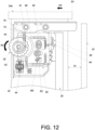
- the second structure 54 is pressed against one of the two sidewalls of the adjusting portion 53 (e.g., a guide groove or a guide channel) and thereby generates a pushing force that displaces the second component 44 and the first component 42 transversely with respect to the third component 50 in a fourth adjustment direction D4 (e.g., toward the left); as a result, the second furniture part 24a is displaced with respect to the first furniture part 22 in the fourth adjustment direction D4 from the first transverse position S1 (see FIG. 8 ) to a third transverse position S3 (see FIG.
- the second indicator feature K2 corresponds no more to the neutral position of the second scale feature M2 (see FIG. 8 ) but to one of the graduation marks of the second scale feature M2 (see FIG. 12 ), in order for the user to check the adjusted position visually.
Landscapes
- Drawers Of Furniture (AREA)
Claims (11)
- Ein Verstellmechanismus (34), umfassend:ein erstes Justiergerät mit:einer ersten Komponente (42);einer zweiten Komponente (44);einem ersten Einstellelement (46), das an der ersten Komponente (42) angebracht ist; undeiner ersten Struktur (48), die an der zweiten Komponente (44)angebracht ist;wobei das erste Einstellelement (46) und die erste Struktur (48) einen ersten Bestandteil (56) bzw. einen zweiten Bestandteil (58) aufweisen, und der erste Bestandteil (56) und der zweite Bestandteil (58) einander entsprechen; und dass, wenn das erste Einstellelement (46) betätigt wird, der erste Bestandteil (56) und der zweite Bestandteil (58) miteinander zusammenwirken, um die zweite Komponente (44) und die erste Komponente (42) aneinander in Längsrichtung zu verschieben und dadurch einzustellen,der Verstellmechanismus (34) weiter ein zweites Justiergerät umfasst, wobei das zweite Justiergerät die folgenden Komponente umfasst:eine dritte Komponente (50);ein zweites Einstellelement (52), das an der zweiten Komponente (44) angebracht ist; undeine zweite Struktur (54), die an der dritten Komponente (50)angebracht ist;worin das zweite Einstellelement (52) einen Verstellteil (53) aufweist;worin, wenn das zweite Einstellelement (52) betätigt wird, der Verstellteil (53) und die zweite Struktur (54) miteinander zusammenwirken, um die zweite Komponente (44) und die dritte Komponente (50) aneinander quer zu verschieben und dadurch einzustellen;wobei der Verstellmechanismus (34) zur Verwendung mit einer Gleitschiene (30) konfiguriert ist; wobei die erste Komponente (42) an einem von der Gleitschiene (30) getragenen Objekt (24a) befestigt werden kann, und die dritte Komponente (50) an die Gleitschiene (30) befestigt werden kann; worin der erste Bestandteil (56) und der zweite Bestandteil (58) so konfiguriert sind, dass sie miteinander zusammenwirken, um eine Drehung des ersten Einstellelements (46) in eine Längsverschiebung der ersten Komponente (42) an der zweiten Komponente (44) umzuwandeln, wodurch eine Längsposition des Objekts (24a) an der Gleitschiene (30) eingestellt wird; und worin der Verstellteil (53) und die zweite Struktur (54) so konfiguriert sind, dass sie miteinander zusammenwirken, um eine Drehung des zweiten Einstellelements (52) in eine Querverschiebung der zweiten Komponente (44) an der dritten Komponente (50) umzuwandeln, wodurch eine Querposition des Objekts (24a) an der Gleitschiene (30) eingestellt wird;worin das erste Einstellelement (46) ein Drehrad ist, die erste Struktur (48) eine Stange ist, die erste Struktur (48) im Wesentlichen in Längsrichtung an der zweiten Komponente (44) angeordnet ist und das erste Einstellelement (46) so konfiguriert ist, dass es durch Drehung um eine durch die erste Struktur (48) definierte Achse betätigt wird;dadurch gekennzeichnet, dass das zweite Einstellelement (52) ein Drehrad ist, die zweite Struktur (54) ein Vorsprung ist, der Verstellteil (53) des zweiten Einstellelements (52) eine allgemein spiralförmige Führungsnut ist und die zweite Struktur (54) in der Führungsnut liegt.
- Der Verstellmechanismus (34) nach Anspruch 1, worin der erste Bestandteil (56) des ersten Einstellelements (46) und der zweite Bestandteil (58) der ersten Struktur (48) ineinander geschraubte Schraubgewinde sind.
- Der Verstellmechanismus (34) nach Anspruch 1, worin die erste Komponente (42) ein Paar von Wänden (60a, 60b) aufweist und das Paar von Wänden (60a, 60b) einen Hohlraum (62) dazwischen zur Aufnahme des ersten Einstellelements (46) definiert; worin die zweite Komponente (44) einen Montageteil (64) zum Tragen der ersten Struktur (48) enthält und die erste Struktur (48) einen ersten angrenzenden Teil (66a) und einen zweiten angrenzenden Teil (66b) aufweist, die sich jeweils auf zwei gegenüberliegenden Seiten des Montageteil (64) befinden; und worin das erste Einstellelement (46) etwas kleiner als der Hohlraum (62) ist und daher durch Drehung um die durch die erste Struktur (48) definierte Achse betätigt werden kann, und das Paar von Wänden (60a, 60b) verhindert, dass das erste Einstellelement (46) in Längsrichtung verschoben wird.
- Der Verstellmechanismus (34) nach einem der Ansprüche 1-3, worin die erste Komponente (42) und die zweite Komponente (44) ein erstes Längsführungselement (70) bzw. ein zweites Längsführungselement (72) aufweisen, das erste Längsführungselement (70) und das zweite Längsführungselement (72) so konfiguriert sind, dass sie miteinander arbeiten, und eines vom ersten Längsführungselement (70) und dem zweiten Längsführungselement (72) größer als das andere vom ersten Längsführungselement (70) und dem zweiten Längsführungselement (72) ist.
- Der Verstellmechanismus (34) nach einem der Ansprüche 1-4, worin die zweite Komponente (44) eine Längsöffnung (74) aufweist, der Verstellmechanismus (34) weiter ein erstes Verbindungsglied (76) aufweist, das erste Verbindungsglied (76) einen Kopfteil (76a) und einen Körper (76b) aufweist, der Kopfteil (76a) größer als der Körper (76b) ist, der Körper (76b) des ersten Verbindungsglieds (76) sich durch einen Abschnitt der Längsöffnung (74) erstreckt und mit der ersten Komponente (42) verbunden ist, und der Kopfteil (76a) des ersten Verbindungsglieds (76) an einer Seite der zweiten Komponente (44) angehalten wird.
- Der Verstellmechanismus (34) nach einem der Ansprüche 1 bis 5, worin die zweite Komponente (44) und die dritte Komponente (50) ein erstes Querführungselement (80) bzw. ein zweites Querführungselement (82) aufweisen, das erste Querführungselement (80) und das zweite Querführungselement (82) so konfiguriert sind, dass sie miteinander arbeiten, und eines vom ersten Querführungselement (80) und dem zweiten Querführungselement (82) größer als das andere vom ersten Querführungselement (80) und dem zweiten Querführungselement (82) ist.
- Der Verstellmechanismus (34) nach einem der Ansprüche 1-6, worin die zweite Komponente (44) mindestens eine Führungsstruktur (84) aufweist, um mindestens einen entsprechenden Randteil (51) der dritten Komponente (50) in Position zu halten.
- Der Verstellmechanismus (34) nach einem der Ansprüche 1-7, worin die dritte Komponente (50) einen ersten Hohlraum (H1) aufweist, und der erste Hohlraum (H1) größer als der Kopfteil (76a) des ersten Verbindungsglieds (76) ist.
- Der Verstellmechanismus (34) nach einem der Ansprüche 1-8, weiter umfassend ein zweites Verbindungsglied (88), worin das zweite Verbindungsglied (88) einen Kopfteil (88a) und einen Körper (88b) aufweist, der Kopfteil (88a) des zweiten Verbindungsglieds (88) größer als der Körper (88b) des zweiten Verbindungsglieds (88) ist, die dritte Komponente (50) eine quer verlaufende Öffnung (86) aufweist, der Körper (88b) des zweiten Verbindungsglieds (88) sich durch einen Teil der Queröffnung (86) der dritten Komponente (50) erstreckt und mit der zweiten Komponente (44) verbunden ist, und der Kopfteil (88a) des zweiten Verbindungsglieds (88) an einer Seite der dritten Komponente (50) angehalten ist.
- Der Verstellmechanismus (34) nach Anspruch 9, worin die erste Komponente (42) einen zweiten Hohlraum (H2) aufweist und der zweite Hohlraum (H2) größer als der Körper (88b) des zweiten Verbindungsglieds (88) ist.
- Der Verstellmechanismus (34) nach einem der Ansprüche 1-10, wobei die dritte Komponente (50) einen Verbindungsteil (90) zum Verbinden der dritten Komponente (50) mit einem Zielobjekt (30) und einen flexiblen Arm (92) mit mehreren Einrasttteilen (92a) zum Eingriff mit dem Zielobjekt (30) aufweist.
Applications Claiming Priority (1)
| Application Number | Priority Date | Filing Date | Title |
|---|---|---|---|
| TW107126812A TWI693043B (zh) | 2018-07-31 | 2018-07-31 | 調整機構 |
Publications (2)
| Publication Number | Publication Date |
|---|---|
| EP3603450A1 EP3603450A1 (de) | 2020-02-05 |
| EP3603450B1 true EP3603450B1 (de) | 2024-08-14 |
Family
ID=64901943
Family Applications (1)
| Application Number | Title | Priority Date | Filing Date |
|---|---|---|---|
| EP19150047.9A Active EP3603450B1 (de) | 2018-07-31 | 2019-01-02 | Justiermechanismus für gleitschiene |
Country Status (4)
| Country | Link |
|---|---|
| US (1) | US10638836B2 (de) |
| EP (1) | EP3603450B1 (de) |
| JP (1) | JP6910337B2 (de) |
| TW (1) | TWI693043B (de) |
Families Citing this family (3)
| Publication number | Priority date | Publication date | Assignee | Title |
|---|---|---|---|---|
| EP4101946A4 (de) | 2020-02-06 | 2025-01-22 | Agc Inc. | Ionenaustauschermembran mit katalysatorschicht, ionenaustauschermembran und elektrolytische hydriervorrichtung |
| TWI717311B (zh) * | 2020-08-28 | 2021-01-21 | 川湖科技股份有限公司 | 滑軌總成 |
| IT202000030218A1 (it) * | 2020-12-09 | 2022-06-09 | Salice Arturo Spa | Dispositivo di aggancio per cassetti |
Citations (7)
| Publication number | Priority date | Publication date | Assignee | Title |
|---|---|---|---|---|
| KR20110090429A (ko) * | 2010-02-04 | 2011-08-10 | 신은순 | 입체이미지 촬영용 트랙 |
| US20140175965A1 (en) * | 2011-09-08 | 2014-06-26 | Arturo Salice S.P.A. | Device And Method For Laterally Centring A Drawer Or The Like On A Pull-Out Guide And A Hooking Device Provided With The Device |
| US8919711B2 (en) * | 2010-02-03 | 2014-12-30 | Julius Blum Gmbh | Coupling device having side adjustment for a drawer |
| EP2850971B1 (de) * | 2013-09-19 | 2016-04-27 | Leonardo S.r.L. | Prozess zum Verhindern einer unbeabsichtigten Rotation von Einstellschrauben eines Aufhängebeschlags |
| CN106090544A (zh) * | 2016-08-12 | 2016-11-09 | 中山大山摄影器材有限公司 | 快速调整摄像平台 |
| CN206462671U (zh) * | 2016-10-04 | 2017-09-05 | 黄云 | 一种抽屉与导轨快速装配结构 |
| TWI616163B (zh) * | 2017-03-07 | 2018-03-01 | 川湖科技股份有限公司 | 用於傢俱部件的連接機構與滑軌總成 |
Family Cites Families (20)
| Publication number | Priority date | Publication date | Assignee | Title |
|---|---|---|---|---|
| US510714A (en) * | 1893-12-12 | Hespere serebriakoff | ||
| US2929804A (en) * | 1955-01-31 | 1960-03-22 | Du Pont | Elastic filaments of linear segmented polymers |
| GB1028063A (en) * | 1962-04-06 | 1966-05-04 | Lubrizol Corp | Grease composition |
| US3372114A (en) * | 1965-02-25 | 1968-03-05 | Lubrizol Corp | Process for preparing thickened mineral oil compositions |
| AT393203B (de) * | 1987-12-07 | 1991-09-10 | Alfit Gmbh | Schublade mit auszugsgarnitur |
| KR200359984Y1 (ko) * | 2004-05-21 | 2004-08-31 | 김하균 | 서랍의 전면판 조립구조 |
| JP3159129U (ja) * | 2009-12-10 | 2010-05-13 | 川湖科技股▲分▼有限公司 | スライドレール構成に用いる補助位置決め装置 |
| US20120092634A1 (en) * | 2010-10-13 | 2012-04-19 | Solak Harun H | Method and apparatus for printing periodic patterns |
| IT1403106B1 (it) * | 2010-12-15 | 2013-10-04 | Salice Arturo Spa | Dispositivo di aggancio di un cassetto ad una guida longitudinale |
| AT13205U1 (de) * | 2011-01-05 | 2013-08-15 | Blum Gmbh Julius | Kupplungsvorrichtung für Schubladen |
| AT510714B1 (de) | 2011-01-05 | 2012-06-15 | Blum Gmbh Julius | Kupplungsvorrichtung für schubladen |
| US8979223B2 (en) | 2012-12-12 | 2015-03-17 | Nan Juen International Co., Ltd. | Adjustable coupling device for connection between sliding rail assembly and a sliding box |
| US9101213B2 (en) * | 2013-11-22 | 2015-08-11 | Hardware Resources, Inc. | Undermount drawer slide position adjustment apparatus and method of use |
| US10149539B2 (en) * | 2013-11-22 | 2018-12-11 | Hardware Resources, Inc. | Undermount drawer slide position adjustment apparatus and method of use |
| CN104840020B (zh) * | 2014-02-14 | 2017-07-11 | 川湖科技股份有限公司 | 滑轨总成及用于滑轨总成的连接装置 |
| US8854769B1 (en) | 2014-04-07 | 2014-10-07 | King Slide Works Co., Ltd. | Slide rail system and connecting device used for slide rail assembly |
| EP2929804B1 (de) * | 2014-04-09 | 2016-09-21 | King Slide Works Co., Ltd. | Verbindungsvorrichtung für eine Auszugsführung und Auszugsführungssystem |
| CN204181228U (zh) * | 2014-11-10 | 2015-03-04 | 广东泰明金属制品有限公司 | 抽屉滑轨的锁紧调节装置 |
| DE202015006943U1 (de) | 2015-10-05 | 2017-01-09 | Grass Gmbh | Vorrichtung zur lösbaren Verbindung eines in einem Möbelkorpus eines Möbelteils über eine Führungseinheit beweglich geführten Möbelauszugs mit der Führungseinheit |
| TWI616164B (zh) * | 2017-03-07 | 2018-03-01 | 川湖科技股份有限公司 | 用於傢俱部件的連接機構與滑軌總成 |
-
2018
- 2018-07-31 TW TW107126812A patent/TWI693043B/zh active
- 2018-12-12 US US16/217,261 patent/US10638836B2/en active Active
- 2018-12-20 JP JP2018237957A patent/JP6910337B2/ja active Active
-
2019
- 2019-01-02 EP EP19150047.9A patent/EP3603450B1/de active Active
Patent Citations (7)
| Publication number | Priority date | Publication date | Assignee | Title |
|---|---|---|---|---|
| US8919711B2 (en) * | 2010-02-03 | 2014-12-30 | Julius Blum Gmbh | Coupling device having side adjustment for a drawer |
| KR20110090429A (ko) * | 2010-02-04 | 2011-08-10 | 신은순 | 입체이미지 촬영용 트랙 |
| US20140175965A1 (en) * | 2011-09-08 | 2014-06-26 | Arturo Salice S.P.A. | Device And Method For Laterally Centring A Drawer Or The Like On A Pull-Out Guide And A Hooking Device Provided With The Device |
| EP2850971B1 (de) * | 2013-09-19 | 2016-04-27 | Leonardo S.r.L. | Prozess zum Verhindern einer unbeabsichtigten Rotation von Einstellschrauben eines Aufhängebeschlags |
| CN106090544A (zh) * | 2016-08-12 | 2016-11-09 | 中山大山摄影器材有限公司 | 快速调整摄像平台 |
| CN206462671U (zh) * | 2016-10-04 | 2017-09-05 | 黄云 | 一种抽屉与导轨快速装配结构 |
| TWI616163B (zh) * | 2017-03-07 | 2018-03-01 | 川湖科技股份有限公司 | 用於傢俱部件的連接機構與滑軌總成 |
Also Published As
| Publication number | Publication date |
|---|---|
| JP6910337B2 (ja) | 2021-07-28 |
| JP2020018828A (ja) | 2020-02-06 |
| EP3603450A1 (de) | 2020-02-05 |
| TW202007312A (zh) | 2020-02-16 |
| US20200037761A1 (en) | 2020-02-06 |
| US10638836B2 (en) | 2020-05-05 |
| TWI693043B (zh) | 2020-05-11 |
Similar Documents
| Publication | Publication Date | Title |
|---|---|---|
| EP3603450B1 (de) | Justiermechanismus für gleitschiene | |
| US9782001B2 (en) | Undermount drawer slide position adjustment apparatus and method of use | |
| US8919711B2 (en) | Coupling device having side adjustment for a drawer | |
| US9066587B1 (en) | Slide rail system and connecting device used for slide rail assembly | |
| US8870313B2 (en) | Pull-out guide for a drawer | |
| EP3398481B1 (de) | Gleitschienenanordnung | |
| US10010174B2 (en) | Mounting mechanism | |
| EP3372114B1 (de) | Kopplungsmechanismus und gleitschienenanordnung für ein möbelteil | |
| US20190216219A1 (en) | Furniture System and Slide Rail Assembly Thereof | |
| EP3451808B1 (de) | Gleitschienenanordnung und montageverfahren für gleitschiene | |
| EP3372115B1 (de) | Kopplungsmechanismus und gleitschienenanordnung für möbelteil | |
| EP3094166B1 (de) | Gleitschienenanordnung | |
| US20140185968A1 (en) | Device for setting a furniture part received in a basic furniture structure, guiding device for moving a movable furniture part and piece of furniture with a device for setting a furniture part received in a basic furniture structure | |
| EP2929804B1 (de) | Verbindungsvorrichtung für eine Auszugsführung und Auszugsführungssystem | |
| US10470568B1 (en) | Adjustment mechanism for slide rail assembly | |
| US10925397B2 (en) | Slide rail mechanism | |
| EP2937018B1 (de) | Auszugsschienensystem mit Verbindungsvorrichtung für Auszugsschienenanordnung | |
| EP3056116B1 (de) | Schienenanordnung | |
| JP3191618U (ja) | スライドレールシステム及び当該スライドレールシステムに用いられる連結装置 | |
| CN110786659B (zh) | 调整机构 | |
| EP3377393A1 (de) | Handbetätigter verschluss für die seitenwände von fahrzeugkarosserien |
Legal Events
| Date | Code | Title | Description |
|---|---|---|---|
| PUAI | Public reference made under article 153(3) epc to a published international application that has entered the european phase |
Free format text: ORIGINAL CODE: 0009012 |
|
| STAA | Information on the status of an ep patent application or granted ep patent |
Free format text: STATUS: REQUEST FOR EXAMINATION WAS MADE |
|
| 17P | Request for examination filed |
Effective date: 20191029 |
|
| AK | Designated contracting states |
Kind code of ref document: A1 Designated state(s): AL AT BE BG CH CY CZ DE DK EE ES FI FR GB GR HR HU IE IS IT LI LT LU LV MC MK MT NL NO PL PT RO RS SE SI SK SM TR |
|
| AX | Request for extension of the european patent |
Extension state: BA ME |
|
| STAA | Information on the status of an ep patent application or granted ep patent |
Free format text: STATUS: EXAMINATION IS IN PROGRESS |
|
| 17Q | First examination report despatched |
Effective date: 20210119 |
|
| GRAP | Despatch of communication of intention to grant a patent |
Free format text: ORIGINAL CODE: EPIDOSNIGR1 |
|
| STAA | Information on the status of an ep patent application or granted ep patent |
Free format text: STATUS: GRANT OF PATENT IS INTENDED |
|
| INTG | Intention to grant announced |
Effective date: 20240312 |
|
| GRAS | Grant fee paid |
Free format text: ORIGINAL CODE: EPIDOSNIGR3 |
|
| GRAA | (expected) grant |
Free format text: ORIGINAL CODE: 0009210 |
|
| STAA | Information on the status of an ep patent application or granted ep patent |
Free format text: STATUS: THE PATENT HAS BEEN GRANTED |
|
| AK | Designated contracting states |
Kind code of ref document: B1 Designated state(s): AL AT BE BG CH CY CZ DE DK EE ES FI FR GB GR HR HU IE IS IT LI LT LU LV MC MK MT NL NO PL PT RO RS SE SI SK SM TR |
|
| REG | Reference to a national code |
Ref country code: GB Ref legal event code: FG4D |
|
| REG | Reference to a national code |
Ref country code: CH Ref legal event code: EP |
|
| REG | Reference to a national code |
Ref country code: DE Ref legal event code: R096 Ref document number: 602019056867 Country of ref document: DE |
|
| REG | Reference to a national code |
Ref country code: IE Ref legal event code: FG4D |
|
| REG | Reference to a national code |
Ref country code: LT Ref legal event code: MG9D |
|
| REG | Reference to a national code |
Ref country code: NL Ref legal event code: MP Effective date: 20240814 |
|
| PG25 | Lapsed in a contracting state [announced via postgrant information from national office to epo] |
Ref country code: NO Free format text: LAPSE BECAUSE OF FAILURE TO SUBMIT A TRANSLATION OF THE DESCRIPTION OR TO PAY THE FEE WITHIN THE PRESCRIBED TIME-LIMIT Effective date: 20241114 |
|
| REG | Reference to a national code |
Ref country code: AT Ref legal event code: MK05 Ref document number: 1712435 Country of ref document: AT Kind code of ref document: T Effective date: 20240814 |
|
| PG25 | Lapsed in a contracting state [announced via postgrant information from national office to epo] |
Ref country code: FI Free format text: LAPSE BECAUSE OF FAILURE TO SUBMIT A TRANSLATION OF THE DESCRIPTION OR TO PAY THE FEE WITHIN THE PRESCRIBED TIME-LIMIT Effective date: 20240814 Ref country code: NL Free format text: LAPSE BECAUSE OF FAILURE TO SUBMIT A TRANSLATION OF THE DESCRIPTION OR TO PAY THE FEE WITHIN THE PRESCRIBED TIME-LIMIT Effective date: 20240814 Ref country code: GR Free format text: LAPSE BECAUSE OF FAILURE TO SUBMIT A TRANSLATION OF THE DESCRIPTION OR TO PAY THE FEE WITHIN THE PRESCRIBED TIME-LIMIT Effective date: 20241115 Ref country code: PT Free format text: LAPSE BECAUSE OF FAILURE TO SUBMIT A TRANSLATION OF THE DESCRIPTION OR TO PAY THE FEE WITHIN THE PRESCRIBED TIME-LIMIT Effective date: 20241216 Ref country code: PL Free format text: LAPSE BECAUSE OF FAILURE TO SUBMIT A TRANSLATION OF THE DESCRIPTION OR TO PAY THE FEE WITHIN THE PRESCRIBED TIME-LIMIT Effective date: 20240814 |
|
| PG25 | Lapsed in a contracting state [announced via postgrant information from national office to epo] |
Ref country code: BG Free format text: LAPSE BECAUSE OF FAILURE TO SUBMIT A TRANSLATION OF THE DESCRIPTION OR TO PAY THE FEE WITHIN THE PRESCRIBED TIME-LIMIT Effective date: 20240814 |
|
| PG25 | Lapsed in a contracting state [announced via postgrant information from national office to epo] |
Ref country code: LV Free format text: LAPSE BECAUSE OF FAILURE TO SUBMIT A TRANSLATION OF THE DESCRIPTION OR TO PAY THE FEE WITHIN THE PRESCRIBED TIME-LIMIT Effective date: 20240814 |
|
| PG25 | Lapsed in a contracting state [announced via postgrant information from national office to epo] |
Ref country code: IS Free format text: LAPSE BECAUSE OF FAILURE TO SUBMIT A TRANSLATION OF THE DESCRIPTION OR TO PAY THE FEE WITHIN THE PRESCRIBED TIME-LIMIT Effective date: 20241214 Ref country code: AT Free format text: LAPSE BECAUSE OF FAILURE TO SUBMIT A TRANSLATION OF THE DESCRIPTION OR TO PAY THE FEE WITHIN THE PRESCRIBED TIME-LIMIT Effective date: 20240814 |
|
| PG25 | Lapsed in a contracting state [announced via postgrant information from national office to epo] |
Ref country code: HR Free format text: LAPSE BECAUSE OF FAILURE TO SUBMIT A TRANSLATION OF THE DESCRIPTION OR TO PAY THE FEE WITHIN THE PRESCRIBED TIME-LIMIT Effective date: 20240814 |
|
| PGFP | Annual fee paid to national office [announced via postgrant information from national office to epo] |
Ref country code: IE Payment date: 20241204 Year of fee payment: 7 |
|
| PG25 | Lapsed in a contracting state [announced via postgrant information from national office to epo] |
Ref country code: RS Free format text: LAPSE BECAUSE OF FAILURE TO SUBMIT A TRANSLATION OF THE DESCRIPTION OR TO PAY THE FEE WITHIN THE PRESCRIBED TIME-LIMIT Effective date: 20241114 Ref country code: ES Free format text: LAPSE BECAUSE OF FAILURE TO SUBMIT A TRANSLATION OF THE DESCRIPTION OR TO PAY THE FEE WITHIN THE PRESCRIBED TIME-LIMIT Effective date: 20240814 |
|
| PG25 | Lapsed in a contracting state [announced via postgrant information from national office to epo] |
Ref country code: RS Free format text: LAPSE BECAUSE OF FAILURE TO SUBMIT A TRANSLATION OF THE DESCRIPTION OR TO PAY THE FEE WITHIN THE PRESCRIBED TIME-LIMIT Effective date: 20241114 Ref country code: PT Free format text: LAPSE BECAUSE OF FAILURE TO SUBMIT A TRANSLATION OF THE DESCRIPTION OR TO PAY THE FEE WITHIN THE PRESCRIBED TIME-LIMIT Effective date: 20241216 Ref country code: PL Free format text: LAPSE BECAUSE OF FAILURE TO SUBMIT A TRANSLATION OF THE DESCRIPTION OR TO PAY THE FEE WITHIN THE PRESCRIBED TIME-LIMIT Effective date: 20240814 Ref country code: NO Free format text: LAPSE BECAUSE OF FAILURE TO SUBMIT A TRANSLATION OF THE DESCRIPTION OR TO PAY THE FEE WITHIN THE PRESCRIBED TIME-LIMIT Effective date: 20241114 Ref country code: NL Free format text: LAPSE BECAUSE OF FAILURE TO SUBMIT A TRANSLATION OF THE DESCRIPTION OR TO PAY THE FEE WITHIN THE PRESCRIBED TIME-LIMIT Effective date: 20240814 Ref country code: LV Free format text: LAPSE BECAUSE OF FAILURE TO SUBMIT A TRANSLATION OF THE DESCRIPTION OR TO PAY THE FEE WITHIN THE PRESCRIBED TIME-LIMIT Effective date: 20240814 Ref country code: IS Free format text: LAPSE BECAUSE OF FAILURE TO SUBMIT A TRANSLATION OF THE DESCRIPTION OR TO PAY THE FEE WITHIN THE PRESCRIBED TIME-LIMIT Effective date: 20241214 Ref country code: HR Free format text: LAPSE BECAUSE OF FAILURE TO SUBMIT A TRANSLATION OF THE DESCRIPTION OR TO PAY THE FEE WITHIN THE PRESCRIBED TIME-LIMIT Effective date: 20240814 Ref country code: GR Free format text: LAPSE BECAUSE OF FAILURE TO SUBMIT A TRANSLATION OF THE DESCRIPTION OR TO PAY THE FEE WITHIN THE PRESCRIBED TIME-LIMIT Effective date: 20241115 Ref country code: FI Free format text: LAPSE BECAUSE OF FAILURE TO SUBMIT A TRANSLATION OF THE DESCRIPTION OR TO PAY THE FEE WITHIN THE PRESCRIBED TIME-LIMIT Effective date: 20240814 Ref country code: ES Free format text: LAPSE BECAUSE OF FAILURE TO SUBMIT A TRANSLATION OF THE DESCRIPTION OR TO PAY THE FEE WITHIN THE PRESCRIBED TIME-LIMIT Effective date: 20240814 Ref country code: BG Free format text: LAPSE BECAUSE OF FAILURE TO SUBMIT A TRANSLATION OF THE DESCRIPTION OR TO PAY THE FEE WITHIN THE PRESCRIBED TIME-LIMIT Effective date: 20240814 Ref country code: AT Free format text: LAPSE BECAUSE OF FAILURE TO SUBMIT A TRANSLATION OF THE DESCRIPTION OR TO PAY THE FEE WITHIN THE PRESCRIBED TIME-LIMIT Effective date: 20240814 |
|
| PGFP | Annual fee paid to national office [announced via postgrant information from national office to epo] |
Ref country code: DE Payment date: 20250102 Year of fee payment: 7 |
|
| PG25 | Lapsed in a contracting state [announced via postgrant information from national office to epo] |
Ref country code: DK Free format text: LAPSE BECAUSE OF FAILURE TO SUBMIT A TRANSLATION OF THE DESCRIPTION OR TO PAY THE FEE WITHIN THE PRESCRIBED TIME-LIMIT Effective date: 20240814 Ref country code: SM Free format text: LAPSE BECAUSE OF FAILURE TO SUBMIT A TRANSLATION OF THE DESCRIPTION OR TO PAY THE FEE WITHIN THE PRESCRIBED TIME-LIMIT Effective date: 20240814 Ref country code: RO Free format text: LAPSE BECAUSE OF FAILURE TO SUBMIT A TRANSLATION OF THE DESCRIPTION OR TO PAY THE FEE WITHIN THE PRESCRIBED TIME-LIMIT Effective date: 20240814 |
|
| PG25 | Lapsed in a contracting state [announced via postgrant information from national office to epo] |
Ref country code: EE Free format text: LAPSE BECAUSE OF FAILURE TO SUBMIT A TRANSLATION OF THE DESCRIPTION OR TO PAY THE FEE WITHIN THE PRESCRIBED TIME-LIMIT Effective date: 20240814 |
|
| PG25 | Lapsed in a contracting state [announced via postgrant information from national office to epo] |
Ref country code: CZ Free format text: LAPSE BECAUSE OF FAILURE TO SUBMIT A TRANSLATION OF THE DESCRIPTION OR TO PAY THE FEE WITHIN THE PRESCRIBED TIME-LIMIT Effective date: 20240814 |
|
| PG25 | Lapsed in a contracting state [announced via postgrant information from national office to epo] |
Ref country code: SK Free format text: LAPSE BECAUSE OF FAILURE TO SUBMIT A TRANSLATION OF THE DESCRIPTION OR TO PAY THE FEE WITHIN THE PRESCRIBED TIME-LIMIT Effective date: 20240814 Ref country code: IT Free format text: LAPSE BECAUSE OF FAILURE TO SUBMIT A TRANSLATION OF THE DESCRIPTION OR TO PAY THE FEE WITHIN THE PRESCRIBED TIME-LIMIT Effective date: 20240814 |
|
| REG | Reference to a national code |
Ref country code: DE Ref legal event code: R097 Ref document number: 602019056867 Country of ref document: DE |
|
| PLBE | No opposition filed within time limit |
Free format text: ORIGINAL CODE: 0009261 |
|
| STAA | Information on the status of an ep patent application or granted ep patent |
Free format text: STATUS: NO OPPOSITION FILED WITHIN TIME LIMIT |
|
| 26N | No opposition filed |
Effective date: 20250515 |
|
| REG | Reference to a national code |
Ref country code: CH Ref legal event code: PL |
|
| PG25 | Lapsed in a contracting state [announced via postgrant information from national office to epo] |
Ref country code: SE Free format text: LAPSE BECAUSE OF FAILURE TO SUBMIT A TRANSLATION OF THE DESCRIPTION OR TO PAY THE FEE WITHIN THE PRESCRIBED TIME-LIMIT Effective date: 20240814 |
|
| PG25 | Lapsed in a contracting state [announced via postgrant information from national office to epo] |
Ref country code: MC Free format text: LAPSE BECAUSE OF FAILURE TO SUBMIT A TRANSLATION OF THE DESCRIPTION OR TO PAY THE FEE WITHIN THE PRESCRIBED TIME-LIMIT Effective date: 20240814 Ref country code: LU Free format text: LAPSE BECAUSE OF NON-PAYMENT OF DUE FEES Effective date: 20250102 |
|
| PG25 | Lapsed in a contracting state [announced via postgrant information from national office to epo] |
Ref country code: BE Free format text: LAPSE BECAUSE OF NON-PAYMENT OF DUE FEES Effective date: 20250131 |
|
| PG25 | Lapsed in a contracting state [announced via postgrant information from national office to epo] |
Ref country code: FR Free format text: LAPSE BECAUSE OF NON-PAYMENT OF DUE FEES Effective date: 20250131 |
|
| PG25 | Lapsed in a contracting state [announced via postgrant information from national office to epo] |
Ref country code: CH Free format text: LAPSE BECAUSE OF NON-PAYMENT OF DUE FEES Effective date: 20250131 |
|
| REG | Reference to a national code |
Ref country code: BE Ref legal event code: MM Effective date: 20250131 |
|
| PGFP | Annual fee paid to national office [announced via postgrant information from national office to epo] |
Ref country code: GB Payment date: 20251106 Year of fee payment: 8 |