EP3351702A1 - Tôle métallique ayant des tubes creux pris en sandwich dans celle-ci et son utilisation - Google Patents
Tôle métallique ayant des tubes creux pris en sandwich dans celle-ci et son utilisation Download PDFInfo
- Publication number
- EP3351702A1 EP3351702A1 EP17821773.3A EP17821773A EP3351702A1 EP 3351702 A1 EP3351702 A1 EP 3351702A1 EP 17821773 A EP17821773 A EP 17821773A EP 3351702 A1 EP3351702 A1 EP 3351702A1
- Authority
- EP
- European Patent Office
- Prior art keywords
- panel
- hollow
- hollow pipes
- metal plate
- hollow pipe
- Prior art date
- Legal status (The legal status is an assumption and is not a legal conclusion. Google has not performed a legal analysis and makes no representation as to the accuracy of the status listed.)
- Pending
Links
- 229910052751 metal Inorganic materials 0.000 title claims abstract description 194
- 239000002184 metal Substances 0.000 title claims abstract description 194
- 238000005219 brazing Methods 0.000 claims abstract description 92
- 239000000945 filler Substances 0.000 claims description 64
- 239000000463 material Substances 0.000 claims description 25
- 229910001220 stainless steel Inorganic materials 0.000 claims description 9
- 239000010935 stainless steel Substances 0.000 claims description 8
- RYGMFSIKBFXOCR-UHFFFAOYSA-N Copper Chemical compound [Cu] RYGMFSIKBFXOCR-UHFFFAOYSA-N 0.000 claims description 7
- 229910052802 copper Inorganic materials 0.000 claims description 7
- 239000010949 copper Substances 0.000 claims description 7
- 239000012774 insulation material Substances 0.000 claims description 6
- 229910000975 Carbon steel Inorganic materials 0.000 claims description 4
- 229910000881 Cu alloy Inorganic materials 0.000 claims description 4
- 229910001069 Ti alloy Inorganic materials 0.000 claims description 4
- RTAQQCXQSZGOHL-UHFFFAOYSA-N Titanium Chemical compound [Ti] RTAQQCXQSZGOHL-UHFFFAOYSA-N 0.000 claims description 4
- 239000010962 carbon steel Substances 0.000 claims description 4
- 239000010936 titanium Substances 0.000 claims description 4
- ATJFFYVFTNAWJD-UHFFFAOYSA-N Tin Chemical compound [Sn] ATJFFYVFTNAWJD-UHFFFAOYSA-N 0.000 claims description 2
- 229910045601 alloy Inorganic materials 0.000 claims description 2
- 239000000956 alloy Substances 0.000 claims description 2
- 229910052782 aluminium Inorganic materials 0.000 claims description 2
- XAGFODPZIPBFFR-UHFFFAOYSA-N aluminium Chemical compound [Al] XAGFODPZIPBFFR-UHFFFAOYSA-N 0.000 claims description 2
- 229910052718 tin Inorganic materials 0.000 claims description 2
- 238000009413 insulation Methods 0.000 abstract description 8
- 238000002955 isolation Methods 0.000 abstract description 3
- 239000007789 gas Substances 0.000 description 52
- 238000010586 diagram Methods 0.000 description 29
- 238000003466 welding Methods 0.000 description 28
- 230000001965 increasing effect Effects 0.000 description 17
- 238000000034 method Methods 0.000 description 13
- 238000010438 heat treatment Methods 0.000 description 12
- 238000005192 partition Methods 0.000 description 11
- 238000005187 foaming Methods 0.000 description 8
- 238000004519 manufacturing process Methods 0.000 description 6
- 230000003014 reinforcing effect Effects 0.000 description 5
- IJGRMHOSHXDMSA-UHFFFAOYSA-N Atomic nitrogen Chemical compound N#N IJGRMHOSHXDMSA-UHFFFAOYSA-N 0.000 description 4
- 238000001816 cooling Methods 0.000 description 4
- 239000002131 composite material Substances 0.000 description 3
- 230000007547 defect Effects 0.000 description 3
- 230000000694 effects Effects 0.000 description 3
- 238000002844 melting Methods 0.000 description 3
- 230000008018 melting Effects 0.000 description 3
- 239000011490 mineral wool Substances 0.000 description 3
- 238000012986 modification Methods 0.000 description 3
- 230000004048 modification Effects 0.000 description 3
- 238000003860 storage Methods 0.000 description 3
- 229920000742 Cotton Polymers 0.000 description 2
- QVGXLLKOCUKJST-UHFFFAOYSA-N atomic oxygen Chemical compound [O] QVGXLLKOCUKJST-UHFFFAOYSA-N 0.000 description 2
- 239000010953 base metal Substances 0.000 description 2
- 230000003247 decreasing effect Effects 0.000 description 2
- 229910052757 nitrogen Inorganic materials 0.000 description 2
- 239000001301 oxygen Substances 0.000 description 2
- 229910052760 oxygen Inorganic materials 0.000 description 2
- 239000003973 paint Substances 0.000 description 2
- 229920002635 polyurethane Polymers 0.000 description 2
- 239000004814 polyurethane Substances 0.000 description 2
- 239000011178 precast concrete Substances 0.000 description 2
- 230000005855 radiation Effects 0.000 description 2
- 238000007493 shaping process Methods 0.000 description 2
- 230000035882 stress Effects 0.000 description 2
- KXGFMDJXCMQABM-UHFFFAOYSA-N 2-methoxy-6-methylphenol Chemical compound [CH]OC1=CC=CC([CH])=C1O KXGFMDJXCMQABM-UHFFFAOYSA-N 0.000 description 1
- UFHFLCQGNIYNRP-UHFFFAOYSA-N Hydrogen Chemical compound [H][H] UFHFLCQGNIYNRP-UHFFFAOYSA-N 0.000 description 1
- 229920005830 Polyurethane Foam Polymers 0.000 description 1
- 239000000853 adhesive Substances 0.000 description 1
- 230000001070 adhesive effect Effects 0.000 description 1
- 230000032683 aging Effects 0.000 description 1
- 239000000969 carrier Substances 0.000 description 1
- 238000006243 chemical reaction Methods 0.000 description 1
- 238000005336 cracking Methods 0.000 description 1
- 230000002950 deficient Effects 0.000 description 1
- 230000002708 enhancing effect Effects 0.000 description 1
- 230000007613 environmental effect Effects 0.000 description 1
- 238000004079 fireproofing Methods 0.000 description 1
- 239000006260 foam Substances 0.000 description 1
- 239000001307 helium Substances 0.000 description 1
- 229910052734 helium Inorganic materials 0.000 description 1
- SWQJXJOGLNCZEY-UHFFFAOYSA-N helium atom Chemical compound [He] SWQJXJOGLNCZEY-UHFFFAOYSA-N 0.000 description 1
- 239000001257 hydrogen Substances 0.000 description 1
- 229910052739 hydrogen Inorganic materials 0.000 description 1
- 239000010954 inorganic particle Substances 0.000 description 1
- JEIPFZHSYJVQDO-UHFFFAOYSA-N iron(III) oxide Inorganic materials O=[Fe]O[Fe]=O JEIPFZHSYJVQDO-UHFFFAOYSA-N 0.000 description 1
- 239000010985 leather Substances 0.000 description 1
- 238000005339 levitation Methods 0.000 description 1
- 239000007788 liquid Substances 0.000 description 1
- 239000007769 metal material Substances 0.000 description 1
- 239000002245 particle Substances 0.000 description 1
- 229920001568 phenolic resin Polymers 0.000 description 1
- 239000005011 phenolic resin Substances 0.000 description 1
- 239000011496 polyurethane foam Substances 0.000 description 1
- 230000002035 prolonged effect Effects 0.000 description 1
- 239000000523 sample Substances 0.000 description 1
- 230000035939 shock Effects 0.000 description 1
- 238000004804 winding Methods 0.000 description 1
Images


Classifications
-
- E—FIXED CONSTRUCTIONS
- E04—BUILDING
- E04C—STRUCTURAL ELEMENTS; BUILDING MATERIALS
- E04C2/00—Building elements of relatively thin form for the construction of parts of buildings, e.g. sheet materials, slabs, or panels
- E04C2/30—Building elements of relatively thin form for the construction of parts of buildings, e.g. sheet materials, slabs, or panels characterised by the shape or structure
- E04C2/32—Building elements of relatively thin form for the construction of parts of buildings, e.g. sheet materials, slabs, or panels characterised by the shape or structure formed of corrugated or otherwise indented sheet-like material; composed of such layers with or without layers of flat sheet-like material
-
- B—PERFORMING OPERATIONS; TRANSPORTING
- B32—LAYERED PRODUCTS
- B32B—LAYERED PRODUCTS, i.e. PRODUCTS BUILT-UP OF STRATA OF FLAT OR NON-FLAT, e.g. CELLULAR OR HONEYCOMB, FORM
- B32B15/00—Layered products comprising a layer of metal
- B32B15/01—Layered products comprising a layer of metal all layers being exclusively metallic
-
- B—PERFORMING OPERATIONS; TRANSPORTING
- B23—MACHINE TOOLS; METAL-WORKING NOT OTHERWISE PROVIDED FOR
- B23K—SOLDERING OR UNSOLDERING; WELDING; CLADDING OR PLATING BY SOLDERING OR WELDING; CUTTING BY APPLYING HEAT LOCALLY, e.g. FLAME CUTTING; WORKING BY LASER BEAM
- B23K1/00—Soldering, e.g. brazing, or unsoldering
- B23K1/0008—Soldering, e.g. brazing, or unsoldering specially adapted for particular articles or work
- B23K1/0014—Brazing of honeycomb sandwich structures
-
- B—PERFORMING OPERATIONS; TRANSPORTING
- B23—MACHINE TOOLS; METAL-WORKING NOT OTHERWISE PROVIDED FOR
- B23K—SOLDERING OR UNSOLDERING; WELDING; CLADDING OR PLATING BY SOLDERING OR WELDING; CUTTING BY APPLYING HEAT LOCALLY, e.g. FLAME CUTTING; WORKING BY LASER BEAM
- B23K1/00—Soldering, e.g. brazing, or unsoldering
- B23K1/012—Soldering with the use of hot gas
-
- B—PERFORMING OPERATIONS; TRANSPORTING
- B23—MACHINE TOOLS; METAL-WORKING NOT OTHERWISE PROVIDED FOR
- B23K—SOLDERING OR UNSOLDERING; WELDING; CLADDING OR PLATING BY SOLDERING OR WELDING; CUTTING BY APPLYING HEAT LOCALLY, e.g. FLAME CUTTING; WORKING BY LASER BEAM
- B23K35/00—Rods, electrodes, materials, or media, for use in soldering, welding, or cutting
- B23K35/02—Rods, electrodes, materials, or media, for use in soldering, welding, or cutting characterised by mechanical features, e.g. shape
- B23K35/0222—Rods, electrodes, materials, or media, for use in soldering, welding, or cutting characterised by mechanical features, e.g. shape for use in soldering, brazing
-
- B—PERFORMING OPERATIONS; TRANSPORTING
- B23—MACHINE TOOLS; METAL-WORKING NOT OTHERWISE PROVIDED FOR
- B23K—SOLDERING OR UNSOLDERING; WELDING; CLADDING OR PLATING BY SOLDERING OR WELDING; CUTTING BY APPLYING HEAT LOCALLY, e.g. FLAME CUTTING; WORKING BY LASER BEAM
- B23K37/00—Auxiliary devices or processes, not specially adapted to a procedure covered by only one of the preceding main groups
- B23K37/003—Cooling means
-
- B—PERFORMING OPERATIONS; TRANSPORTING
- B23—MACHINE TOOLS; METAL-WORKING NOT OTHERWISE PROVIDED FOR
- B23P—METAL-WORKING NOT OTHERWISE PROVIDED FOR; COMBINED OPERATIONS; UNIVERSAL MACHINE TOOLS
- B23P15/00—Making specific metal objects by operations not covered by a single other subclass or a group in this subclass
-
- B—PERFORMING OPERATIONS; TRANSPORTING
- B29—WORKING OF PLASTICS; WORKING OF SUBSTANCES IN A PLASTIC STATE IN GENERAL
- B29C—SHAPING OR JOINING OF PLASTICS; SHAPING OF MATERIAL IN A PLASTIC STATE, NOT OTHERWISE PROVIDED FOR; AFTER-TREATMENT OF THE SHAPED PRODUCTS, e.g. REPAIRING
- B29C44/00—Shaping by internal pressure generated in the material, e.g. swelling or foaming ; Producing porous or cellular expanded plastics articles
- B29C44/02—Shaping by internal pressure generated in the material, e.g. swelling or foaming ; Producing porous or cellular expanded plastics articles for articles of definite length, i.e. discrete articles
- B29C44/12—Incorporating or moulding on preformed parts, e.g. inserts or reinforcements
- B29C44/1214—Anchoring by foaming into a preformed part, e.g. by penetrating through holes
-
- B—PERFORMING OPERATIONS; TRANSPORTING
- B32—LAYERED PRODUCTS
- B32B—LAYERED PRODUCTS, i.e. PRODUCTS BUILT-UP OF STRATA OF FLAT OR NON-FLAT, e.g. CELLULAR OR HONEYCOMB, FORM
- B32B15/00—Layered products comprising a layer of metal
-
- B—PERFORMING OPERATIONS; TRANSPORTING
- B32—LAYERED PRODUCTS
- B32B—LAYERED PRODUCTS, i.e. PRODUCTS BUILT-UP OF STRATA OF FLAT OR NON-FLAT, e.g. CELLULAR OR HONEYCOMB, FORM
- B32B15/00—Layered products comprising a layer of metal
- B32B15/01—Layered products comprising a layer of metal all layers being exclusively metallic
- B32B15/011—Layered products comprising a layer of metal all layers being exclusively metallic all layers being formed of iron alloys or steels
-
- B—PERFORMING OPERATIONS; TRANSPORTING
- B32—LAYERED PRODUCTS
- B32B—LAYERED PRODUCTS, i.e. PRODUCTS BUILT-UP OF STRATA OF FLAT OR NON-FLAT, e.g. CELLULAR OR HONEYCOMB, FORM
- B32B15/00—Layered products comprising a layer of metal
- B32B15/01—Layered products comprising a layer of metal all layers being exclusively metallic
- B32B15/013—Layered products comprising a layer of metal all layers being exclusively metallic one layer being formed of an iron alloy or steel, another layer being formed of a metal other than iron or aluminium
- B32B15/015—Layered products comprising a layer of metal all layers being exclusively metallic one layer being formed of an iron alloy or steel, another layer being formed of a metal other than iron or aluminium the said other metal being copper or nickel or an alloy thereof
-
- B—PERFORMING OPERATIONS; TRANSPORTING
- B32—LAYERED PRODUCTS
- B32B—LAYERED PRODUCTS, i.e. PRODUCTS BUILT-UP OF STRATA OF FLAT OR NON-FLAT, e.g. CELLULAR OR HONEYCOMB, FORM
- B32B15/00—Layered products comprising a layer of metal
- B32B15/04—Layered products comprising a layer of metal comprising metal as the main or only constituent of a layer, which is next to another layer of the same or of a different material
- B32B15/043—Layered products comprising a layer of metal comprising metal as the main or only constituent of a layer, which is next to another layer of the same or of a different material of metal
-
- B—PERFORMING OPERATIONS; TRANSPORTING
- B32—LAYERED PRODUCTS
- B32B—LAYERED PRODUCTS, i.e. PRODUCTS BUILT-UP OF STRATA OF FLAT OR NON-FLAT, e.g. CELLULAR OR HONEYCOMB, FORM
- B32B3/00—Layered products comprising a layer with external or internal discontinuities or unevennesses, or a layer of non-planar shape; Layered products comprising a layer having particular features of form
- B32B3/10—Layered products comprising a layer with external or internal discontinuities or unevennesses, or a layer of non-planar shape; Layered products comprising a layer having particular features of form characterised by a discontinuous layer, i.e. formed of separate pieces of material
- B32B3/12—Layered products comprising a layer with external or internal discontinuities or unevennesses, or a layer of non-planar shape; Layered products comprising a layer having particular features of form characterised by a discontinuous layer, i.e. formed of separate pieces of material characterised by a layer of regularly- arranged cells, e.g. a honeycomb structure
-
- B—PERFORMING OPERATIONS; TRANSPORTING
- B32—LAYERED PRODUCTS
- B32B—LAYERED PRODUCTS, i.e. PRODUCTS BUILT-UP OF STRATA OF FLAT OR NON-FLAT, e.g. CELLULAR OR HONEYCOMB, FORM
- B32B3/00—Layered products comprising a layer with external or internal discontinuities or unevennesses, or a layer of non-planar shape; Layered products comprising a layer having particular features of form
- B32B3/10—Layered products comprising a layer with external or internal discontinuities or unevennesses, or a layer of non-planar shape; Layered products comprising a layer having particular features of form characterised by a discontinuous layer, i.e. formed of separate pieces of material
- B32B3/18—Layered products comprising a layer with external or internal discontinuities or unevennesses, or a layer of non-planar shape; Layered products comprising a layer having particular features of form characterised by a discontinuous layer, i.e. formed of separate pieces of material characterised by an internal layer formed of separate pieces of material which are juxtaposed side-by-side
- B32B3/20—Layered products comprising a layer with external or internal discontinuities or unevennesses, or a layer of non-planar shape; Layered products comprising a layer having particular features of form characterised by a discontinuous layer, i.e. formed of separate pieces of material characterised by an internal layer formed of separate pieces of material which are juxtaposed side-by-side of hollow pieces, e.g. tubes; of pieces with channels or cavities
-
- B—PERFORMING OPERATIONS; TRANSPORTING
- B32—LAYERED PRODUCTS
- B32B—LAYERED PRODUCTS, i.e. PRODUCTS BUILT-UP OF STRATA OF FLAT OR NON-FLAT, e.g. CELLULAR OR HONEYCOMB, FORM
- B32B37/00—Methods or apparatus for laminating, e.g. by curing or by ultrasonic bonding
- B32B37/06—Methods or apparatus for laminating, e.g. by curing or by ultrasonic bonding characterised by the heating method
-
- E—FIXED CONSTRUCTIONS
- E04—BUILDING
- E04C—STRUCTURAL ELEMENTS; BUILDING MATERIALS
- E04C2/00—Building elements of relatively thin form for the construction of parts of buildings, e.g. sheet materials, slabs, or panels
- E04C2/02—Building elements of relatively thin form for the construction of parts of buildings, e.g. sheet materials, slabs, or panels characterised by specified materials
- E04C2/08—Building elements of relatively thin form for the construction of parts of buildings, e.g. sheet materials, slabs, or panels characterised by specified materials of metal, e.g. sheet metal
-
- E—FIXED CONSTRUCTIONS
- E04—BUILDING
- E04C—STRUCTURAL ELEMENTS; BUILDING MATERIALS
- E04C2/00—Building elements of relatively thin form for the construction of parts of buildings, e.g. sheet materials, slabs, or panels
- E04C2/30—Building elements of relatively thin form for the construction of parts of buildings, e.g. sheet materials, slabs, or panels characterised by the shape or structure
- E04C2/34—Building elements of relatively thin form for the construction of parts of buildings, e.g. sheet materials, slabs, or panels characterised by the shape or structure composed of two or more spaced sheet-like parts
- E04C2/36—Building elements of relatively thin form for the construction of parts of buildings, e.g. sheet materials, slabs, or panels characterised by the shape or structure composed of two or more spaced sheet-like parts spaced apart by transversely-placed strip material, e.g. honeycomb panels
- E04C2/365—Building elements of relatively thin form for the construction of parts of buildings, e.g. sheet materials, slabs, or panels characterised by the shape or structure composed of two or more spaced sheet-like parts spaced apart by transversely-placed strip material, e.g. honeycomb panels by honeycomb structures
-
- F—MECHANICAL ENGINEERING; LIGHTING; HEATING; WEAPONS; BLASTING
- F16—ENGINEERING ELEMENTS AND UNITS; GENERAL MEASURES FOR PRODUCING AND MAINTAINING EFFECTIVE FUNCTIONING OF MACHINES OR INSTALLATIONS; THERMAL INSULATION IN GENERAL
- F16L—PIPES; JOINTS OR FITTINGS FOR PIPES; SUPPORTS FOR PIPES, CABLES OR PROTECTIVE TUBING; MEANS FOR THERMAL INSULATION IN GENERAL
- F16L59/00—Thermal insulation in general
-
- B—PERFORMING OPERATIONS; TRANSPORTING
- B23—MACHINE TOOLS; METAL-WORKING NOT OTHERWISE PROVIDED FOR
- B23K—SOLDERING OR UNSOLDERING; WELDING; CLADDING OR PLATING BY SOLDERING OR WELDING; CUTTING BY APPLYING HEAT LOCALLY, e.g. FLAME CUTTING; WORKING BY LASER BEAM
- B23K2101/00—Articles made by soldering, welding or cutting
- B23K2101/04—Tubular or hollow articles
- B23K2101/045—Hollow panels
-
- B—PERFORMING OPERATIONS; TRANSPORTING
- B23—MACHINE TOOLS; METAL-WORKING NOT OTHERWISE PROVIDED FOR
- B23K—SOLDERING OR UNSOLDERING; WELDING; CLADDING OR PLATING BY SOLDERING OR WELDING; CUTTING BY APPLYING HEAT LOCALLY, e.g. FLAME CUTTING; WORKING BY LASER BEAM
- B23K35/00—Rods, electrodes, materials, or media, for use in soldering, welding, or cutting
- B23K35/22—Rods, electrodes, materials, or media, for use in soldering, welding, or cutting characterised by the composition or nature of the material
- B23K35/24—Selection of soldering or welding materials proper
- B23K35/30—Selection of soldering or welding materials proper with the principal constituent melting at less than 1550 degrees C
- B23K35/302—Cu as the principal constituent
-
- B—PERFORMING OPERATIONS; TRANSPORTING
- B32—LAYERED PRODUCTS
- B32B—LAYERED PRODUCTS, i.e. PRODUCTS BUILT-UP OF STRATA OF FLAT OR NON-FLAT, e.g. CELLULAR OR HONEYCOMB, FORM
- B32B2307/00—Properties of the layers or laminate
- B32B2307/50—Properties of the layers or laminate having particular mechanical properties
- B32B2307/544—Torsion strength; Torsion stiffness
-
- B—PERFORMING OPERATIONS; TRANSPORTING
- B32—LAYERED PRODUCTS
- B32B—LAYERED PRODUCTS, i.e. PRODUCTS BUILT-UP OF STRATA OF FLAT OR NON-FLAT, e.g. CELLULAR OR HONEYCOMB, FORM
- B32B2419/00—Buildings or parts thereof
-
- B—PERFORMING OPERATIONS; TRANSPORTING
- B32—LAYERED PRODUCTS
- B32B—LAYERED PRODUCTS, i.e. PRODUCTS BUILT-UP OF STRATA OF FLAT OR NON-FLAT, e.g. CELLULAR OR HONEYCOMB, FORM
- B32B2605/00—Vehicles
- B32B2605/08—Cars
-
- B—PERFORMING OPERATIONS; TRANSPORTING
- B32—LAYERED PRODUCTS
- B32B—LAYERED PRODUCTS, i.e. PRODUCTS BUILT-UP OF STRATA OF FLAT OR NON-FLAT, e.g. CELLULAR OR HONEYCOMB, FORM
- B32B2605/00—Vehicles
- B32B2605/12—Ships
-
- B—PERFORMING OPERATIONS; TRANSPORTING
- B32—LAYERED PRODUCTS
- B32B—LAYERED PRODUCTS, i.e. PRODUCTS BUILT-UP OF STRATA OF FLAT OR NON-FLAT, e.g. CELLULAR OR HONEYCOMB, FORM
- B32B2605/00—Vehicles
- B32B2605/18—Aircraft
-
- E—FIXED CONSTRUCTIONS
- E04—BUILDING
- E04B—GENERAL BUILDING CONSTRUCTIONS; WALLS, e.g. PARTITIONS; ROOFS; FLOORS; CEILINGS; INSULATION OR OTHER PROTECTION OF BUILDINGS
- E04B1/00—Constructions in general; Structures which are not restricted either to walls, e.g. partitions, or floors or ceilings or roofs
- E04B1/62—Insulation or other protection; Elements or use of specified material therefor
- E04B1/74—Heat, sound or noise insulation, absorption, or reflection; Other building methods affording favourable thermal or acoustical conditions, e.g. accumulating of heat within walls
- E04B2001/742—Use of special materials; Materials having special structures or shape
- E04B2001/748—Honeycomb materials
Definitions
- the present invention relates to the technical field of composite materials, and in particular, to a hollow pipe-sandwiching metal plate and applications thereof.
- honeycomb plates have the following defects: (1). As low-and-medium-temperature welding is adopted usually, for example, a welding temperature is 200°C to 300°C, once a honeycomb plate is affected by a high temperature, for example, a fire occurs, it will lead to a great decrease in the strength of the honeycomb plate, the honeycomb plate may even fall apart, and therefore such honeycomb plates cannot be used in bearing structures. Because the honeycomb plates are extremely sensitive to environmental changes, the durability of bearing structures will be greatly decreased, and moreover, the life is short, and safety is poor. (2). As honeycomb cores are normally arranged tightly together, during heating, gas flow cannot flow uniformly in the honeycomb cores.
- the honeycomb cores generally can be welded only by means of radiation heating. Heating by using this heating method is slow, easily leading to nonuniform heating of a workpiece. Consequently, thermal deformation is engendered, a defective rate is increased greatly, service life is shortened, and production costs are increased. Furthermore, after heating is complete, the workpiece needs to be transported into a cooling chamber for cooling, and therefore heating and cooling cannot be completed in one step. As a result, working time is prolonged greatly, and the efficiency is lowered.
- the welding between the honeycomb cores and panels is not firm, linear-contact or point-contact welding is adopted most, and overall stability is poor.
- the objective of the present invention is to provide a hollow pipe-sandwiching metal plate with light weight, high strength, low stress, pressure-bearing ability, heat-insulating ability and high temperature resistance and applications thereof to overcome the above-mentioned defects of the prior art.
- the hollow pipe-sandwiching metal plate of the present invention comprises a first panel, a second panel, and multiple hollow pipes between the first panel and the second panel; a gap is arranged between at least two hollow pipes, and the hollow pipes are connected to the first panel and the second panel by brazing.
- gas passages are arranged among the hollow pipes.
- High-temperature gas is utilized to flow through the gas passages for heating to braze the hollow pipes to the first panel and the second panel.
- the structure of the metal plate can be integrated with a brazing process, which, in comparison with methods, such as radiation heating applied on the outer surface of the metal plate, has the following advantages: on one hand, the high-temperature gas runs through the inner cavity of the metal plate and is in contact with the hollow pipes, so that temperatures at all positions of the metal plate are close, consequently, temperature uniformity is increased greatly, and deformation cannot be caused due to thermal difference; on the other hand, heating time can be shortened, and the efficiency and quality of brazing can be increased.
- the through gas passages can be one or any combination of three types of structures including horizontal gas passages, longitudinal gas passages and oblique gas passages.
- the temperature of the above-mentioned high-temperature gas needs to be higher than the temperature of the brazing filler metal used in brazing but lower than the temperature of base metal, so that the brazing filler metal can be melted while the base metal is not damaged.
- the high-temperature gas can be shielding gas, such as nitrogen, helium or hydrogen.
- Cold gas can be utilized to flow through the gas passages to decrease temperature to cool the hollow pipes, the first panel and the second panel for shaping.
- each hollow pipe is provided with a flange; the multiple hollow pipes all are hollow pipes with flanges; or the multiple hollow pipes include hollow pipes with flanges and hollow pipes without flanges.
- the flanges can enlarge the welding areas between the hollow pipes and the panels, increasing the brazing strength of the hollow pipes.
- Each flange of the invention can be a contact surface bent outwardly along the end of the hollow pipe or a contact surface bent inwardly along the end of the hollow pipe; the flange can also be separately arranged contact surfaces extending outwardly along the end of the hollow pipe, such as at least two symmetrical semicircles or at least two symmetrical strips, or another specially shaped structure, such as a petal shape; and the flange can also be a contact surface which is turned out horizontally along the end of the hollow pipe and bent downwardly. Any of the above-mentioned flange structures can enlarge the welding areas between the hollow pipes and the panels.
- each of part of the hollow pipes may be provided with the flange, and the other hollow pipes may not be provided with flanges.
- each hollow pipe can be of a closed structure, a hollow structure, a semi-closed structure or the like.
- the closed structure can be a structure, the inner cavity of which is hollow and the ends of which are closed, or can be a closed structure in which the above-mentioned flange is turned inwardly to cover the end of the hollow pipe.
- the semi-closed structure can be that the inner cavity of the hollow pipe is semi-closed, or can be that the tubular wall of the hollow pipe is semi-closed, for example, the tubular wall is provided with a slot, the opening of which is small, or the hollow pipe is provided with multiple holes.
- each hollow pipe is a circle or an ellipse or an N-sided polygon, wherein N is greater than or equal to 3.
- the N-sided polygon can be a triangle, a square, a pentagon, etc.
- each hollow pipe is a circular hollow pipe, which has advantages, such as uniform stress, uneasy deformation and high stability, moreover, the production process is simple, and the cost is low.
- N is greater than 5, and the higher the value of N is, the more each hollow pipe approximates to the circular hollow pipe.
- first panel and the second panel are flat panels or curved panels, or one panel is a flat panel and the other panel is a curved panel.
- the curved panel can be applied to hulls, frameworks and so on with any curved structures, and the line form of the curved panel can be curved, wavy, etc.; and the shape of the flat panel can be set according to requirements.
- the first panel and the second panel can be arranged in parallel, or can be arranged non-parallelly.
- the axes of the hollow pipes are perpendicular to tangent lines to the curved surfaces of the curved panels, in this way, the strength of connection between the hollow pipes and the panels can be enhanced, and lack of welding at multiple positions of the hollow pipes or production of crevices or holes is prevented.
- the material of the first panel and/or the second panel is a stainless steel, carbon steel, titanium or copper alloy plate.
- a high-temperature-resistant material is adopted to produce the first panel and the second panel, so that the hollow pipe-sandwiching metal plate can have effects, such as fire proofing.
- the material of the hollow pipes is a stainless steel, carbon steel, titanium or copper alloy plate.
- the hollow pipes are connected to the first panel and the second panel through brazing filler metal by brazing, and copper, aluminum, tin or alloy brazing filler metal is adopted as the brazing filler metal.
- the brazing filler metal is a material with a high melting point and can resist high temperature.
- the hollow pipes are connected to the first panel and the second panel through brazing filler metal by brazing, and the brazing filler metal is laid directly or arranged in the form of loops between the hollow pipes and the first panel and between the hollow pipes and the second panel.
- “In the form of loops” means that the brazing filler metal rings or encircles the hollow pipes.
- the hollow pipes are provided with gas holes.
- the hollow pipes via the gas holes, the hollow pipes can be vacuumized and filled with shielding gas and/or reducing gas to ensure that the inner cavities of the hollow pipes are under an oxygen-free environment and a reducing environment, ensuring that the hollow pipes cannot be oxidized, and thereby the strength and quality of the whole structure are ensured; and on the other hand, via the gas holes, a thermal insulation material, such as raw foaming solution, can be injected.
- the gas hole can be arranged at any position of the hollow pipe, preferably, the gas hole is arranged at the upper part of the hollow pipe, and more preferably, the gas hole is arranged at a position 5 mm to 20 mm away from the top of the hollow pipe, which can help to discharge gas with density lower than that of the air, such as oxygen.
- the thermal insulation material is arranged in the inner cavities of the hollow pipes and/or between the adjacent hollow pipes.
- the hollow pipe-sandwiching metal plate can have the effects of thermal insulation, sound insulation and vibration isolation.
- the thermal insulation material can be one or any combination of sintered particles, sawdust, inorganic cotton, foaming material and so on.
- the thermal insulation material such as foaming material
- the foaming material can be raw polyurethane solution or raw phenolic resin solution; in addition, the foaming material injected into the hollow pipes not only plays the role of thermal insulation, but also can reduce convection in the pipe bodies, enhancing the effect of sound insulation; furthermore, the filling foamed layer can serve as a supporting structure to prevent the hollow pipes from being bent and increase the supporting force of the hollow pipes; moreover, the service life of the foam is long, and because there is no air inside, cracking, various reactions and so on won't occur.
- a border is arranged on at least one of the sides of the circumference of the first panel and/or the second panel.
- the multiple hollow pipes are limited by limiting metal, and the multiple hollow pipes in any row are connected into a whole through the limiting metal;
- the limiting metal is brazing filler metal, the brazing filler metal is provided with holes corresponding to the positions of the hollow pipes, and the edges of the holes are provided with limiting structures for limiting the hollow pipes; or the limiting metal is shaped like a sheet, a strip or a wire.
- the above-mentioned limiting metal means a metal material capable of limiting the hollow pipes, such as brazing filler metal, metal wires and metal sheets, wherein the metal wires each can be of a strip structure, and are connected to the hollow pipes by way of welding or winding; and the metal wires can also be of annular structures, and encircle and are welded to the hollow pipes.
- brazing filler metal there is at least one piece of brazing filler metal; when there is more than one piece of brazing filler metal, the multiple hollow pipes are divided into multiple groups, and each group corresponds to one piece of brazing filler metal.
- each metal sheet is provided with multiple projections, and each projection is connected to one hollow pipe corresponding to its position.
- the multiple hollow pipes in any row are connected into a whole through the limiting metal
- the multiple hollow pipes in any row are connected into a whole through the limiting metal
- the metal wires can limit any combination of the hollow pipes in the horizontal and longitudinal rows, the horizontal and oblique rows, the longitudinal and oblique rows, the horizontal rows, the longitudinal rows or the oblique rows.
- the material of the above-mentioned limiting metal can be the same as or different from a base material.
- the limiting structures are flanges which downwardly extend out from the brazing filler metal along the edges of the holes, and the holes limit the hollow pipes by means of the flanges; or each limiting portion consists of limiting projections extending outwardly from the brazing filler metal along the edge of one hole and a flange downwardly extending out along the edge of the hole, and the holes limit the hollow pipes by means of the flanges, and stick the hollow pipes by means of the limiting projections.
- the shape of the limiting projection can be of any structure, such as a curved, polygonal or irregularly-shaped structure, as long as the hollow pipes can be stuck.
- brazing filler metal is hollowed out at non-hollow-pipe positions, and thus, the piling of excessive brazing filler metal can be prevented in the process of heating.
- the multiple hollow pipes can be arranged optionally into different shapes, such as a square, a polygon or another shape.
- Another hollow pipe-sandwiching metal plate of the present invention comprises a first panel, a second panel, and multiple hollow pipes between the first panel and the second panel; a gap is arranged between at least two hollow pipes, the hollow pipes are connected to the first panel and the second panel by brazing, and the edges of the panels are flanged or not flanged.
- the plate when the panels are flanged, another plate which is perpendicular to the panel extends out from the edge of each panel, the plate can substitute for the above-mentioned border, and hollow pipes can also be added on the plate, so that a metal plate with a corner is formed.
- the hollow pipe-sandwiching metal plate comprises a first panel, a second panel, and a plurality of hollow pipes between the first panel and the second panel, and is used as a material for a building structure, a vehicle, a ship, an aircraft, aerospace equipment, a container, a bridge, a road, a tunnel, a railway foundation, furniture, a culvert, a vacuum pipeline or a case; a gap is arranged between at least two hollow pipes, and the hollow pipes are connected to the first panel and the second panel by brazing.
- the building structure can be but is not limited to girders, columns, floor plates, walls, balconies and awnings.
- the vehicle can be sedans, coaches, trucks, cementing trucks, etc., or can be metros, light rails, magnetic levitation, municipal railways, streetcars, etc.
- the ships can be steamships, aircraft carriers, etc.
- the aircraft can be airliners, helicopters, gliders, etc.
- the metal plate can be used as hulls, frameworks and accessory materials of the above-mentioned means, and the accessory materials can be engine hoods, reinforcing rib plates, bulkheads, etc.
- the aerospace equipment can be a spacecraft, such as a satellite, a spaceship or a probe.
- a container body of the container is made of the metal plates.
- the container body can comprise a bottom plate, a top plate, side plates, doors, etc.
- a bridge body of the bridge is made of the metal plates.
- the bridge can be an overpass, a pedestrian overpass, a boarding bridge for planes, etc.
- the bridge body can comprise a bridge deck, steps, guardrails, supporting bodies, etc.
- the road is made of the metal plates.
- the road can be a street, a runway, an indoor floor, etc..
- the body, the lining and so on of the tunnel can be made of the metal plates.
- the railway foundation is normally a ballastless track, and the metal plates can substitute for a shockproof layer and an anti-seepage layer between precast concrete members, the railway foundation and precast concrete members.
- a furniture body of the furniture is made of the metal plates.
- the furniture can be a table, a chair, a cabinet, a bed, etc.
- a culvert body of the culvert is made of the metal plates.
- a pipe body of the vacuum pipeline is made of the metal plates.
- the vacuum pipe is a vacuum transportation pipeline.
- a case body of the case is made of the metal plates.
- the case can be a tool kit, a suitcase, a storage box, etc.
- the metal plate of the present invention can be used in any engineering field, and has advantages, such as light weight, high strength, rust resistance, aging resistance, eternal life, thermal insulation, vibration isolation and good stability, moreover, the metal plate is easy and convenient to connect or assemble, and time and labor can be saved.
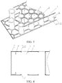
- a hollow pipe-sandwiching metal plate comprises a first panel 1, a second panel 2, and multiple hollow pipes 3 between the first panel 1 and the second panel 2; gaps are arranged among the multiple hollow pipes 3, and the hollow pipes 3 are connected to the first panel 1 and the second panel 2 by brazing.
- each hollow pipe 3 is a circle, and each hollow pipe 3 is of a hollow structure. A certain distance is arranged between each two adjacent hollow pipes 3.
- each hollow pipe 3 The upper and lower ends of each hollow pipe 3 are provided with flanges 5-1, which are turned outward to form circles.
- the flanges 5-1 of the hollow pipes 3 are connected to the first panel 1 and the second panel 2 through brazing filler metal 4 by brazing, and the brazing filler metal 4 is laid directly between the hollow pipes 3 and the two panels.
- the brazing filler metal 4 is copper brazing filler metal.
- Both the first panel 1 and the second panel 2 are flat panels.
- the first panel 1, the second panel 2 and the hollow pipes 3 are all made of stainless steel.
- Each hollow pipe 3 is provided with a gas hole 31, and the gas hole 31 is arranged at a position 10 mm away from the top of the hollow pipe.
- shielding gas can be injected into the hollow pipes 3, and when the content of oxygen is very low, reducing gas can be injected to reduce oxide layers of the stainless steel hollow pipes.
- the gas can be discharged via the gas holes 31.
- the hollow pipes can be filled with a foaming material (such as raw polyurethane solution) via the gas holes, and the foaming material can be foamed into polyurethane foam in the hollow pipes; and besides, foaming inorganic particles can also be arranged in the hollow pipes in advance.
- a foaming material such as raw polyurethane solution
- the arrangement gaps among the hollow pipes can also be filled with inorganic cotton, such as mineral wool.
- the mineral wool is block-like, and its size can match the gaps among the hollow pipes, so that each piece of mineral wool can be just tightly put into the gaps among the hollow pipes.
- brazing filler metal 4' is punched and flanged, so that the hollow pipes 3 are nested in flanges 41' of the brazing filler metal 4' and limited.
- the brazing filler metal 4' is provided with hollows 6 at non-hollow-pipe positions.
- the difference from embodiment 2 is that the front edges and the rear edges of the multiple hollow pipes 3 are provided with borders 7, the borders 7 adopt stainless steel, and the borders 7, the first panel 1 and the second panel 2 are connected into a whole by brazing.
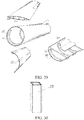
- each hollow pipe 3 is provided with flanges 5-2, each flange 5-2 consists of two semicircular structures which are arranged symmetrically on the hollow pipe, and the flanges 5-2 of the hollow pipes are connected to the first panel and the second panel by brazing.
- each hollow pipe 3' is a square
- both the upper and lower ends of the hollow pipe 3' are provided with flanges 5-3
- each flange 5-3 consists of two bent structures which are arranged symmetrically on the hollow pipe
- the flanges 5-3 of the hollow pipes are connected to the first panel and the second panel by brazing.
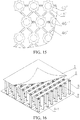
- the difference from embodiment 2 is that through gas passages 8 are arranged among the multiple hollow pipes 3, and high-temperature gas is utilized to flow forward, backward, leftward and rightward through the gas passages 8 for heating to braze the hollow pipes 3 to the first panel 1 and the second panel 2.
- the hollow pipes 3 are circular pipes, and the number of the hollow pipes can be chosen according to requirements.
- the adjacent hollow pipes 3 are arranged at intervals, forming horizontal gas passages 81 and longitudinal gas passages 82.
- the high-temperature gas gets into the inner cavity of the metal plate via the horizontal gas passages 81 and the longitudinal gas passages 82.
- the hollow pipes 3 are brazed to the first panel and the second panel through brazing filler metal by means of the high-temperature gas, and the brazing filler metal is laid between the hollow pipes and the first panel and between the hollow pipes and the second panel.
- the brazing filler metal is copper brazing filler metal, the temperature of the high-temperature gas is higher than the melting point of copper, and is lower than the melting point of the material of the first panel, the second panel and the hollow pipes, in this way, the copper brazing filler metal can be melted by the high-temperature gas, and the liquid copper brazing filler metal is utilize to wet the base material, fill the gaps of connection and diffuse with the base material, so that fixed connection is achieved.
- cold gas is utilized to flow forward, backward, leftward and rightward through the horizontal gas passages 81 and the longitudinal gas passages 82 to cool the hollow pipes 3, the first panel and the second panel for shaping. Both the high-temperature gas and the cold gas are nitrogen.
- a connecting plate can be inserted between each two adjacent rows of hollow pipes, the connecting plate is provided with branches, the positions of the branches correspond to the positions of the gas holes 31, the branches are inserted in the holes, and the two adjacent rows of hollow pipes are exhausted from one end of the connecting plate, so that the hollow pipes are under an oxygen-free environment.
- both the first panel 1' and the second panel 2' are curved panels. Both ends of the hollow pipes 3 are connected perpendicularly to the contact surfaces of the panels.
- the line form of the curved panel is curved, the multiple hollow pipes 3 are arranged at intervals, the axis of each hollow pipe 3 is perpendicular to a tangent line of a corresponding curve, thus, the strength of connection between the hollow pipes 3 and the panels can be enhanced, brazing nonuniformity caused by lack of welding at multiple positions of the hollow pipes or production of crevices or holes is prevented, and thereby the solution can greatly increase overall strength and quality.
- the first panel 1' and the second panel 2' have the same shape.
- the central angle of the curved panel can be designed to be large, or can be designed to be small.
- the difference from embodiment 8 is that the first panel 1' is a curved panel, the second panel 2 is a flat panel, the ends of the hollow pipes 3" which are connected to the curved panel are parallel or approximately parallel to the contact surface of the curved plate, both the upper and lower ends of the hollow pipes 3" are provided with flanges, the flanges are parallel or approximately parallel to the contact surface of the curved plate, consequently, the hollow pipes 3" and the curved panel can be welded firmly, lack of welding at multiple positions of the hollow pipes or production of crevices or holes is prevented, and thereby overall strength and quality are increased greatly.
- both the first panel 1' and the second panel 2' are curved panels, and the line form of the curved panels is wavy.
- both the first panel and the second panel are flat panels, and moreover, the first panel is not parallel to the second panel, that is, the first panel is arranged obliquely, and the second panel is arranged horizontally.
- the end of each hollow pipe, which is connected to the first panel, is a slope, both the upper and lower ends of the hollow pipes are provided with flanges, the flanges are parallel or approximately parallel to the contact surface of the first panel, consequently, the hollow pipes and the curved panel can be welded firmly, lack of welding at multiple positions of the hollow pipes or production of crevices or holes is prevented, and thereby overall strength and quality are increased greatly.
- brazing filler metal 4' in the present embodiment is sheet, and brazing filler metal 1 is punched and flanged.
- the multiple hollow pipes 3 are arranged into multiple rows, each longitudinal row corresponds to one piece of brazing filler metal 4', and holes 42' in each brazing filler metal 4' correspond to the number of each row of hollow pipes 3.
- the multiple hollow pipes 3 are arranged into nine rows, the upper end and the lower end of each longitudinal row respectively correspond to one piece of brazing filler metal 4', and there are 18 pieces of brazing filler metal in total.
- the difference from embodiment 12 is that the brazing filler metal 4' is shaped like a strip, and multiple holes 42' with walls 43' are connected directly into a whole through connecting ribs 44' to form the brazing filler metal 4'.
- limiting projections 45' extend outwardly from the brazing filler metal 4' along the edge of each hole 42', and each hole 42' hoops one hollow pipe 3 by means of the flange 41', and sticks the hollow pipe by means of the limiting projections 45'.
- limiting projections 45' there are two limiting projections 45' in the present embodiment, and the limiting projections 45' are arranged symmetrically, and are shaped like strips.
- the difference from embodiment 14 is that there are four limiting projections 45', which are arranged symmetrically.
- the brazing filler metal 4' is one-piece, and the brazing filler metal 4' is hollowed out or punched at non-hollow-pipe positions, that is, the holes 42' are connected through brazing filler metal connecting ribs 46'.
- Each brazing filler metal connecting rib 46' is provided with a slot 461', so that the brazing filler metal is saved greatly.
- the difference from embodiment 12 is that the hollow pipes are limited by metal sheets 9 rather than the brazing filler metal.
- the brazing filler metal can be laid between the hollow pipes and the panels.
- the upper ends and the lower ends of the hollow pipes 3 in each two adjacent horizontal rows respectively share one metal sheet 9, furthermore, both the upper ends and the lower ends of the hollow pipes 3 are provided with flanges 5-1, the metal sheet 9 is connected to the flange of the upper end/lower end of each hollow pipe in the horizontal rows by welding, and preferably, the metal sheet 9 is connected to the bottom surfaces of the flanges 5-1 of the hollow pipes by welding, for example, adopting an electric resistance welding method.
- the material of the metal sheets 9 is stainless steel.
- the metal sheet as a limiting structure in the present embodiment forms the multiple hollow pipes 3 into a whole, that is, a module with certain specifications is formed.
- the multiple hollow pipes can be placed as a whole, consequently, the speed of assembly is increased greatly, and thereby working efficiency is increased.
- such an integral limiting method can ensure that every hollow pipe won't shift and topple down, greatly increasing the accuracy of the positions of the hollow pipes, and thereby brazing quality is increased.
- the difference from embodiment 12 is that the hollow pipes 3 are limited by metal wires 10 rather than the brazing filler metal.
- the brazing filler metal can be laid between the hollow pipes and the panels.
- both sides of the upper ends and the lower ends of the hollow pipes 3 in each row respectively share one metal wire 10, the metal wires 10 are welded to the flanges 5-1 of each hollow pipe, and thereby the metal wires 10 connect this row of hollow pipes 3 into a whole.
- the hollow pipes in two oblique rows are then chosen, metal wires 10 are respectively welded to the upper and lower ends, and thus, among the hollow pipes in each horizontal row, two hollow pipes are connected by metal wires in the oblique rows.
- Such a connection method can form all the hollow pipes into a module with certain specifications, that is, all the hollow pipes are connected into a whole.
- the advantages are as follows: on one hand, in the process of assembling the hollow pipes and the panels, the speed of assembly can be increased greatly, and thereby working efficiency is increased; on the other hand, it can be ensured that every hollow pipe won't shift and topple down, greatly increasing the accuracy of the positions of the hollow pipes, and thereby brazing quality is increased.
- the metal wire 10 is of a line-shaped structure, and the material is a stainless steel wire.
- each longitudinal row corresponds to one piece of brazing filler metal
- the holes in the brazing filler metal correspond to the number of each row of hollow pipes
- each two adjacent longitudinal rows correspond to one piece of brazing filler metal
- the holes in each piece of brazing filler metal correspond to the number of the hollow pipes in each two adjacent longitudinal rows.
- each hollow pipe is greater than that of a pentagon and less than or equal to that of a decagon, for example, the hollow pipe is a hexagonal pipe, a heptagonal pipe, an octagonal pipe or a nonagonal pipe.
- a bridge body 11 of a bridge structure comprises piers 111, bent caps 112, supporting beams 113, and a bridge deck 114, the bent caps 112 are arranged on the piers 111, the supporting beams 113 span the multiple bent caps 112 by means of supports 115, and the bridge deck 114 is connected to the supporting beams 113.
- At least one structure among the piers 111, the bent caps 112, the supporting beams 113 and the bridge deck 114 is made of any one of the hollow pipe-sandwiching metal plates in embodiments 1-19.
- Both the supporting beams 113 and the bridge deck 114 can be respectively made of one hollow pipe-sandwiching metal plate, or can be made by assembling multiple hollow pipe-sandwiching metal plates.
- Both the piers 111 and the bent caps 112 can be respectively formed into a columnar structure by assembling four hollow pipe-sandwiching metal plates.
- All the metal plates are connected by welding into the bridge structure, and are reinforced by bolts.
- the bridge body which is made of the metal plates has the advantages of high strength, good bearing capability, shock resistance, light self-weight, fireproofness and disassemblability.
- a door comprises a door body 12, and the door body 12 is made of any one of the hollow pipe-sandwiching metal plates in embodiments 1-19.
- the out layer of the hollow pipe-sandwiching metal plate is wrapped by a surface decorative material 121 such as a veneer or paint.
- the door which is made of the metal plate has the advantages of high strength, good thermal insulation, light self-weight and fireproofness.
- a storage cabinet comprises a cabinet body 13, and partitions 131 are arranged in the cabinet body 13, wherein at least one structure among the cabinet body 13 and the partitions 131 is made of any one of the hollow pipe-sandwiching metal plates in embodiments 1-19.
- the multiple metal plates are connected through multiple bolts into the cabinet body structure.
- the partitions 131 are divided into horizontal partitions and vertical partitions, and the vertical partitions are connected to the inner wall of the cabinet body through bolts; and the horizontal partitions are also connected to the cabinet body and the vertical partitions through bolts.
- the storage cabinet which is made of the metal plates has the advantages of high strength, good thermal insulation, light self-weight and fireproofness.
- a vacuum pipeline comprises a pipe body 14, the pipe body 14 is made of the four hollow pipe-sandwiching metal plates described in embodiment 8, and the metal plates are assembled into a pipeline structure, the cross section of which is circular.
- the multiple metal plates are assembled into a whole by adopting the welding method, and are reinforced by bolts.
- the vacuum pipeline can be used for hyperloop transportation, etc.
- a container body 15 of a container comprises a top plate 151, a bottom plate 152, side plates 153, and an end plate 154, one end of the container body 15 is provided with a container door, the two ends of the container body 15 are provided with frames 155, and the corners of the container body 15 are provided with hoisting holes 156.
- At least one structure among the top plate 151, the bottom plate 152, the side plates 153, the end plate 154, the container door and the frames 155 is made of any one of the hollow pipe-sandwiching metal plates in embodiments 1-19.
- the top plate 151, the bottom plate 152, the side plates 153, the end plate 154, the container door and the frames 155 are connected by welding and are reinforced by bolts.
- a case body 16 of a suitcase is made of any one of the hollow pipe-sandwiching metal plates in embodiments 1-19.
- the out layer of the hollow pipe-sandwiching metal plate is wrapped by a surface decorative material such as leather or paint.
- a body 17 of a tunnel is made of a lining 171
- a partition plate 172 is connected to the top in the body 17, and at least one structure among the lining 171 and the partition plate 172 is made of any one of the hollow pipe-sandwiching metal plates in embodiments 1-19.
- the multiple metal plates of the lining are welded and bolted to form the body of the tunnel, and the partition plate 172 is connected to the inner cavity of the lining 171 through bolts.
- the multiple hollow pipe-sandwiching metal plates described in any one of embodiments 1-19 are spliced to form a road, and can be connected through bolts, and thus, after being damaged, one metal plate can be dismantled directly and be replaced by a new metal plate, without affecting transportation.
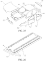
- a sedan comprises a sedan body 18, the sedan body comprises an engine hood 181, a front bumper 182, a frame 183, a roof 184, front fenders 185, front doors 186, back doors 187, and a trunk lid 188, wherein at least one structure among the engine hood 181, the front bumper 182, the frame 183, the roof 184, the front fenders 185, the front doors 186, the back doors 187 and the trunk lid 188 is made of any one of the hollow pipe-sandwiching metal plates in embodiments 1-19.
- the metal plates as well as the metal plates and the other parts of the sedan body can be connected by hinging, welding, bolting and other ways to form a sedan body structure.
- a track body 19 of a ballastless track comprises a foundation 191, a track plate 192, and a fastener system 193, and the foundation 191 is connected to the track plate 192 through flexible adhesive 194.
- the multiple hollow pipe-sandwiching metal plates in any one of embodiments 1-19 are spliced to form at least one structure of the foundation 191 and the track plate 192, and can be fixed by welding and/or bolting.
- a train body 20 of a rail train comprises carriage wall plates 201 and floors 202.
- a track plate 204 is arranged in the vacuum pipeline 203.
- At least one structure among the carriage wall plates 201, the floors 202 and the track plate 204 is made of any one of the hollow pipe-sandwiching metal plates in embodiments 1-19.
- the vacuum pipeline 203 is made of the hollow pipe-sandwiching metal plates described in embodiment 8. The metal plates as well as the metal plates and the other parts of the car body can be connected by hinging, welding, bolting and other ways to form a train body structure, a pipeline structure or a track plate structure.
- a ship body 21 of a ship structure comprises a hull 211, reinforcing plates 212, compartment bulkheads 213, and reinforcing bulkheads 214, and at least one structure among the hull 211, the reinforcing plates 212, the compartment bulkheads 213 and the reinforcing bulkheads 214 is made of any one of the hollow pipe-sandwiching metal plates in embodiments 1-19.
- the metal plates as well as the metal plates and the other parts of the ship body can be connected by hinging, welding, bolting and other ways to form a ship body structure.
- a plane body 22 of a plane comprises a fuselage, wings, and a plane bottom, wherein the fuselage comprises a fuselage skin 221, and first bulkheads 222 and longerons 223 arranged in the inner cavity of the fuselage skin 221.
- Each wing comprises a wing skin 224 and longitudinal walls 225 arranged in the inner cavity of the wing skin.
- the plane bottom comprises a floor 226, the fuselage skin 221, and second bulkheads 227 and crossbeams 228 arranged in the inner cavity of the fuselage skin.
- At least one structure among the fuselage skin 221, the first bulkheads 222, the longerons 223, the wing skins 224, the longitudinal walls 225, the floor 226, the second bulkheads 227 and the crossbeams 228 is made of any one of the hollow pipe-sandwiching metal plates in embodiments 1-19.
- the plane body is completely of an arc-shaped structure, and is preferably made of the hollow pipe-sandwiching metal plates described in embodiment 8.
- the metal plates as well as the metal plates and the other parts of the plane body can be connected by hinging, welding, bolting and other ways to form the plane body structure.
- a column body 23 of a building bearing column consists of the four hollow pipe-sandwiching metal plates in any one of embodiments 1-19; and the four metal plates define a square shape, and are connected with one another to form the building bearing column.
- the metal plates can be connected by welding, bolting or another way.
Landscapes
- Engineering & Computer Science (AREA)
- Architecture (AREA)
- Civil Engineering (AREA)
- Structural Engineering (AREA)
- Mechanical Engineering (AREA)
- General Engineering & Computer Science (AREA)
- Physics & Mathematics (AREA)
- Optics & Photonics (AREA)
- Laminated Bodies (AREA)
- Panels For Use In Building Construction (AREA)
- Butt Welding And Welding Of Specific Article (AREA)
- Thermal Insulation (AREA)
Applications Claiming Priority (7)
| Application Number | Priority Date | Filing Date | Title |
|---|---|---|---|
| CN201610967446.0A CN108005302A (zh) | 2016-10-31 | 2016-10-31 | 一种翻边芯材 |
| CN201710069311.7A CN108397679B (zh) | 2017-02-08 | 2017-02-08 | 一种夹芯金属板材 |
| CN201710465352.8A CN109128567B (zh) | 2017-06-19 | 2017-06-19 | 一种钎焊料结构、钎焊夹芯复合板及其组装方式 |
| CN201710621594.1A CN109304528A (zh) | 2017-07-27 | 2017-07-27 | 一种钎焊夹芯复合板限位结构 |
| CN201710621595.6A CN109304901A (zh) | 2017-07-27 | 2017-07-27 | 一种钎焊夹芯复合板限位结构 |
| CN201710700964 | 2017-08-16 | ||
| PCT/CN2017/103301 WO2018076984A1 (fr) | 2016-10-31 | 2017-09-26 | Tôle métallique ayant des tubes creux pris en sandwich dans celle-ci et son utilisation |
Publications (2)
| Publication Number | Publication Date |
|---|---|
| EP3351702A1 true EP3351702A1 (fr) | 2018-07-25 |
| EP3351702A4 EP3351702A4 (fr) | 2019-04-10 |
Family
ID=62024360
Family Applications (1)
| Application Number | Title | Priority Date | Filing Date |
|---|---|---|---|
| EP17821773.3A Pending EP3351702A4 (fr) | 2016-10-31 | 2017-09-26 | Tôle métallique ayant des tubes creux pris en sandwich dans celle-ci et son utilisation |
Country Status (19)
| Country | Link |
|---|---|
| US (2) | US10920422B2 (fr) |
| EP (1) | EP3351702A4 (fr) |
| JP (1) | JP6793751B2 (fr) |
| KR (1) | KR102184163B1 (fr) |
| AU (1) | AU2017338254B2 (fr) |
| CA (1) | CA3008499C (fr) |
| CL (1) | CL2018001761A1 (fr) |
| CO (1) | CO2018004852A2 (fr) |
| CR (1) | CR20180122A (fr) |
| IL (1) | IL258984B (fr) |
| MX (1) | MX2018006994A (fr) |
| MY (1) | MY195356A (fr) |
| NZ (1) | NZ741337A (fr) |
| PE (1) | PE20190951A1 (fr) |
| PH (1) | PH12018500990A1 (fr) |
| SA (1) | SA518400080B1 (fr) |
| SG (1) | SG11201805175VA (fr) |
| WO (1) | WO2018076984A1 (fr) |
| ZA (1) | ZA201801128B (fr) |
Families Citing this family (12)
| Publication number | Priority date | Publication date | Assignee | Title |
|---|---|---|---|---|
| EP3884121A1 (fr) * | 2018-11-21 | 2021-09-29 | Autotelic Holding LLC | Partie centrale de bâtiment |
| CN109530956B (zh) * | 2018-12-28 | 2020-12-22 | 远大可建科技有限公司 | 一种钎料、芯管与钎料的焊接装置及方法 |
| CN110801090A (zh) * | 2019-11-22 | 2020-02-18 | 耒阳市汉客箱包有限公司 | 一种耐磨旅行箱 |
| JP7402981B2 (ja) * | 2020-06-23 | 2023-12-21 | 富士フイルム株式会社 | 構造体及び構造体の製造方法 |
| CN111824325B (zh) * | 2020-07-09 | 2022-01-11 | 漳浦县金浦钢丝厂 | 一种高强度抗压镀锌板 |
| CN111843098B (zh) * | 2020-07-23 | 2021-05-04 | 吉林大学 | 一种铝蜂窝板钎焊用夹具及钎焊工艺 |
| CN112356523B (zh) * | 2020-08-29 | 2021-12-07 | 南京航空航天大学 | 基于可编程刚度的手性胞元构建的梯度点阵吸能结构及其3d打印方法 |
| CN112317896B (zh) * | 2020-10-23 | 2022-02-22 | 航天特种材料及工艺技术研究所 | 一种真空封装外防护结构的一体化制备方法 |
| KR102277253B1 (ko) * | 2020-11-26 | 2021-07-13 | 코오롱이앤씨 주식회사 | Cts슬래브를 활용한 신속 건축공정용 라멘 구조 시스템 및 그 시공방법 |
| KR102509900B1 (ko) * | 2021-03-03 | 2023-03-15 | 코오롱이앤씨 주식회사 | 중공 건식 슬래브의 단부에 보 형성용 채널이 일체로 형성된 단위부재를 이용한 스피드 건설공법 |
| CN113510443B (zh) * | 2021-05-13 | 2023-06-23 | 国网上海市电力公司 | 一种电力压接管制造加工工艺 |
| CN114012352B (zh) * | 2021-09-25 | 2024-03-19 | 苏州华创特材股份有限公司 | 一种电力机车侧墙弦梁用钢管生产工艺 |
Family Cites Families (100)
| Publication number | Priority date | Publication date | Assignee | Title |
|---|---|---|---|---|
| US1465653A (en) * | 1921-10-31 | 1923-08-21 | Axel E Olander | Wall construction |
| US2538495A (en) * | 1947-01-04 | 1951-01-16 | Bell Telephone Labor Inc | Metallic container sealing method |
| US2837788A (en) * | 1955-07-18 | 1958-06-10 | Dante V Mazzocco | Panel core constructions |
| US3072225A (en) * | 1955-10-17 | 1963-01-08 | Solar Aircraft Co | Honeycomb sandwich structure |
| US2822609A (en) * | 1955-11-10 | 1958-02-11 | Niphos Corp | Brazing process |
| US3061054A (en) * | 1958-08-18 | 1962-10-30 | Milo R Simmonds | Fastening methods and means for structural sandwiches |
| US3110961A (en) * | 1959-04-06 | 1963-11-19 | North American Aviation Inc | Honeycomb sandwich panel brazing |
| US3156041A (en) * | 1960-04-18 | 1964-11-10 | Frank M Gault | Method of soldering and brazing structural elements |
| US3328218A (en) * | 1962-04-09 | 1967-06-27 | Noyes Howard | Process of making a structural element |
| US3355850A (en) * | 1964-02-14 | 1967-12-05 | Frederick W Rohe | Insert with ends riveted to panel skins |
| US3490187A (en) * | 1967-05-23 | 1970-01-20 | Harry K Stauffer | Building component |
| US3526072A (en) * | 1968-03-29 | 1970-09-01 | James R Campbell | Load distributing system for panels incorporating honeycomb core |
| US3750248A (en) * | 1968-06-14 | 1973-08-07 | Emhart Corp | Method for making evaporator or condenser construction |
| US3664906A (en) * | 1970-01-26 | 1972-05-23 | Du Pont | Structural panel of ribbed structures of thermoplastic resin |
| GB1432241A (en) * | 1972-04-19 | 1976-04-14 | Industrialised Building System | Structural building panels |
| US4027058A (en) * | 1975-07-23 | 1977-05-31 | Wootten William A | Folded structural panel |
| US4034135A (en) * | 1975-11-20 | 1977-07-05 | Passmore Michael Edward Anthon | Rigid structure |
| US4257998A (en) * | 1978-05-01 | 1981-03-24 | The Boenig Company | Method of making a cellular core with internal septum |
| SE420750B (sv) * | 1978-11-17 | 1981-10-26 | Ingemanssons Ingenjorsbyra Ab | Ljudisolerande byggnadselement med stor styvhet |
| USRE35098E (en) * | 1979-12-20 | 1995-11-28 | Modine Manufacturing Co. | Method of making a heat exchanger |
| US4348848A (en) * | 1980-04-01 | 1982-09-14 | Denzer Walter L | Segregated slab structural products |
| US4470357A (en) * | 1983-01-17 | 1984-09-11 | Caesar Sanzaro | Laminated panels for vault construction |
| US4489234A (en) * | 1983-03-25 | 1984-12-18 | General Electric Company | Radiant-energy heating and/or cooking apparatus with honeycomb coverplate |
| US4572700A (en) * | 1983-03-31 | 1986-02-25 | Monsanto Company | Elongated bendable drainage mat |
| GB2167699B (en) * | 1984-12-04 | 1988-04-27 | Sanden Corp | A method for producing a heat exchanger |
| DE3624986A1 (de) * | 1986-07-24 | 1988-02-04 | Focke & Co | Maschine, insbesondere verpackungsmaschine |
| US5360500A (en) * | 1986-11-20 | 1994-11-01 | Dunlop Limited | Method of producing light-weight high-strength stiff panels |
| JPH069738Y2 (ja) * | 1987-01-23 | 1994-03-16 | 株式会社ゼクセル | 管材のろう付け構造 |
| US5197244A (en) * | 1988-10-31 | 1993-03-30 | Kabushiki Kaisha Toshiba | Interior panel unit for permitting arrangement of cables and devices on room floor |
| US5116689A (en) * | 1988-11-07 | 1992-05-26 | Rohr Industries, Inc. | Apparatus and method for selectively increasing density and thermal conductivity of honeycomb structures |
| US5150520A (en) * | 1989-12-14 | 1992-09-29 | The Allen Group Inc. | Heat exchanger and method of assembly thereof |
| US5433151A (en) * | 1990-09-07 | 1995-07-18 | Hitachi, Ltd. | Railway car body structures and methods of making them using welded honeycomb panels connected in an edge to edge relation |
| US5036913A (en) * | 1990-11-05 | 1991-08-06 | Valeo Engine Cooling, Incorporated | Vehicle radiator with tube to header joint formed of a composite weld and solder bond |
| JPH04288957A (ja) * | 1991-03-05 | 1992-10-14 | Toshiba Corp | 凝縮器用のフィンチュ−ブ式熱交換器の製造方法 |
| US5188879A (en) * | 1991-07-15 | 1993-02-23 | Sorrento Engineering Corporation | Polyimide foam filled structures |
| US5487930A (en) * | 1991-10-03 | 1996-01-30 | Tolo, Inc. | Three structure structural element with interlocking ribbing |
| FR2687465A1 (fr) * | 1992-02-14 | 1993-08-20 | Valeo Thermique Moteur Sa | Tubulure de raccordement pour une boite a fluide d'echangeur de chaleur et boite a fluide munie d'une telle tubulure. |
| JPH083443Y2 (ja) * | 1992-04-24 | 1996-01-31 | 有限会社クリーン・アップ・システム | 排水・保水装置 |
| US5445861A (en) * | 1992-09-04 | 1995-08-29 | The Boeing Company | Lightweight honeycomb panel structure |
| KR950009505B1 (ko) * | 1993-03-05 | 1995-08-23 | 주식회사두원공조 | 자동차의 에어콘용 열교환기의 제조방법 |
| EP0741638A4 (fr) * | 1994-01-26 | 1998-12-02 | Peter Sing | Materiaux de construction a structure sandwich |
| NZ282881A (en) * | 1994-03-31 | 1997-10-24 | British Steel Plc | Double skin panel comprising facing steel plates 2mm to 32mm thick joined by cross-members which are of 100mm to 800mm length and which are spaced apart by 15 to 50 times the plate thickness and for filling with concrete |
| WO1995026856A1 (fr) * | 1994-03-31 | 1995-10-12 | British Steel Plc | Ameliorations apportees a des structures composites a double paroi |
| US5492069A (en) * | 1994-07-18 | 1996-02-20 | E. I. Du Pont De Nemours And Company | Pallet assembly |
| JP3172986B2 (ja) * | 1994-12-21 | 2001-06-04 | 日本軽金属株式会社 | ハニカムパネル |
| JPH08174727A (ja) * | 1994-12-21 | 1996-07-09 | Nippon Light Metal Co Ltd | ハニカムパネル |
| JPH08192485A (ja) * | 1995-01-19 | 1996-07-30 | Nippon Light Metal Co Ltd | ハニカムパネル及びその製造方法 |
| US5716693A (en) * | 1995-11-06 | 1998-02-10 | Pittman; Douglas E. | High strength, lightweight pressurized structure for use as the skin of a spacecraft or other vehicle |
| DE19615505C2 (de) * | 1996-04-19 | 2001-09-06 | Bluemle Blueco Technik | Doppelplattenkörper |
| US6297489B1 (en) * | 1996-05-02 | 2001-10-02 | Hamamatsu Photonics K.K. | Electron tube having a photoelectron confining mechanism |
| US6004652A (en) * | 1996-09-13 | 1999-12-21 | Clark; Brian Hall | Structural dimple panel |
| US6412243B1 (en) * | 1997-04-30 | 2002-07-02 | Franklin S. Sutelan | Ultra-lite modular composite building system |
| US6055790A (en) * | 1998-05-18 | 2000-05-02 | The United States Of America As Represented By The Secretary Of The Air Force | Thermal conductive insert for sandwich structures |
| GB2344864A (en) * | 1998-12-17 | 2000-06-21 | Textron Fastening Syst Ltd | Blind fastener |
| US6129146A (en) * | 1999-05-17 | 2000-10-10 | Krueger; David L. | Manifold for a brazed radiator |
| US6834469B2 (en) * | 2001-01-24 | 2004-12-28 | Geotek, Inc. | Utility line support member |
| FR2820716B1 (fr) * | 2001-02-15 | 2003-05-30 | Eads Airbus Sa | Procede de degivrage par circulation forcee d'un fluide, d'un capot d'entree d'air de moteur a reaction et dispositif pour sa mise en oeuvre |
| US7575795B2 (en) * | 2002-04-02 | 2009-08-18 | Seamless Alteratory Technologies, Inc (Satech) | Impact absorbing safety matting system with elastomeric sub-surface structure |
| JP2004108070A (ja) * | 2002-09-19 | 2004-04-08 | Kaho Seisakusho:Kk | 透視遮蔽用ガラリ装置 |
| US20060151155A1 (en) * | 2003-01-27 | 2006-07-13 | Showa Denko K.K. | Heat exchanger and process for fabricating same |
| US6817586B1 (en) * | 2003-08-08 | 2004-11-16 | Ching-Chiang Lin | Paper pallet |
| KR200350066Y1 (ko) * | 2003-09-24 | 2004-05-14 | 박기호 | 허니컴(Honeycomb) 제조방법 |
| JP4038497B2 (ja) * | 2004-07-06 | 2008-01-23 | 株式会社ミヤテック | 断熱性パネル |
| US10352484B2 (en) * | 2004-08-05 | 2019-07-16 | Faurecia Emissions Control Technologies Germany Gmbh | Exhaust system |
| JP4696236B2 (ja) * | 2005-02-16 | 2011-06-08 | 国立大学法人広島大学 | コンドロイチンの製造方法 |
| US7958681B2 (en) * | 2005-06-02 | 2011-06-14 | Moller Jr Jorgen J | Modular floor tile with nonslip insert system |
| CN1748486A (zh) * | 2005-08-22 | 2006-03-22 | 薛斌凯 | 蜂窝复合板芯板 |
| US20070256379A1 (en) * | 2006-05-08 | 2007-11-08 | Edwards Christopher M | Composite panels |
| DE102006028956A1 (de) * | 2006-06-23 | 2008-01-24 | Airbus Deutschland Gmbh | Flugzeugseitenverkleidung |
| US8141723B2 (en) * | 2006-08-18 | 2012-03-27 | Plano Molding Company | Inverted cell honeycomb structure shelving |
| WO2008127301A1 (fr) * | 2006-10-27 | 2008-10-23 | University Of Virginia Patent Foundation | Fabrication de structures de ferme en treillis à partir de matériaux monolithiques |
| CN100560350C (zh) | 2007-02-23 | 2009-11-18 | 辽宁科技大学 | 金属蜂窝夹芯组合吸能结构材料及其制备方法 |
| US8097106B2 (en) * | 2007-06-28 | 2012-01-17 | The Boeing Company | Method for fabricating composite structures having reinforced edge bonded joints |
| FI125708B (fi) * | 2007-09-11 | 2016-01-15 | Outokumpu Oy | Paneelirakenne |
| DE102007051628B4 (de) * | 2007-10-26 | 2009-11-26 | Zimmer, Günther | Teleskopdübel II und Setzverfahren |
| JP5004371B2 (ja) * | 2008-04-30 | 2012-08-22 | キョーラク株式会社 | サンドイッチパネル用芯材およびサンドイッチパネル用芯材の成形方法、ならびにサンドイッチパネルおよびサンドイッチパネルの成形方法 |
| US20100223730A1 (en) * | 2008-10-03 | 2010-09-09 | Edizone, Llc | Cushions comprising core structures having joiner ribs and related methods |
| RU2531330C2 (ru) * | 2008-12-23 | 2014-10-20 | Вудвелдинг Аг | Способ крепления соединителя и соединитель |
| CN201567737U (zh) * | 2009-10-28 | 2010-09-01 | 江苏华浠新型建材有限公司 | 金属面铝蜂窝夹芯板 |
| US8403007B1 (en) * | 2009-10-29 | 2013-03-26 | Vittorio Marinelli | Rivet plumbing repair apparatus and method |
| US8590247B2 (en) * | 2009-11-12 | 2013-11-26 | Duke Ellington Cooke | Ceiling anchoring device with locking rail system |
| US20110240280A1 (en) * | 2010-03-31 | 2011-10-06 | Kabushiki Kaisha Kobe Seiko Sho (Kobe Steel, Ltd.) | Aluminum alloy brazing sheet and heat exchanger |
| DE102010018676B4 (de) * | 2010-04-28 | 2012-02-09 | Dbw Holding Gmbh | Wärmedämm- oder Isolierblech im Fahrzeugbereich aus einem flächigen Halbzeug aus Metall |
| US9845600B2 (en) * | 2011-07-01 | 2017-12-19 | Embry-Riddle Aeronautical University, Inc. | Highly vented truss wall honeycomb structures |
| CN202359876U (zh) * | 2011-11-24 | 2012-08-01 | 张梦之 | 一种纸蜂窝复合挡板围墙 |
| US20150211230A1 (en) * | 2011-12-20 | 2015-07-30 | Margarita Jimenez Horwitz | Module for building facades and method of use in construction |
| CN103192551B (zh) * | 2012-01-09 | 2016-12-07 | 辽宁辽杰科技有限公司 | 一种具有蜂窝结构芯板的中空夹芯板材及其制备方法 |
| US9664396B2 (en) * | 2012-11-08 | 2017-05-30 | Iis Institute For Independent Studies Gmbh | Building envelope and method for adjusting the temperature in a building |
| PT2781762T (pt) * | 2013-03-20 | 2019-01-30 | Ruag Schweiz Ag | Estrutura de suporte leve, método para produção de uma estrutura de suporte leve, painel sanduíche composto e método para produção de um painel sanduíche composto |
| JP2014188996A (ja) * | 2013-03-28 | 2014-10-06 | Mitsubishi Aircraft Corp | ハニカムコアサンドイッチ構造体の修理方法および修理結果物 |
| CN105682897A (zh) * | 2013-10-04 | 2016-06-15 | 泽菲罗斯公司 | 插入件的粘附方法和装置 |
| JP2016017666A (ja) * | 2014-07-07 | 2016-02-01 | 株式会社ケーヒン・サーマル・テクノロジー | 熱交換器およびその製造方法 |
| EP3267138B1 (fr) * | 2015-03-02 | 2019-02-06 | Denso Corporation | Échangeur de chaleur |
| JP2017029989A (ja) * | 2015-07-29 | 2017-02-09 | 株式会社Uacj | アルミニウム構造体の製造方法 |
| WO2017049130A1 (fr) * | 2015-09-17 | 2017-03-23 | Sps Technologies, Llc | Insert ajustable pour structure en sandwich |
| KR101774322B1 (ko) * | 2015-12-22 | 2017-09-04 | 엘지전자 주식회사 | 공기조화기 및 그 제조방법 |
| US10016955B2 (en) * | 2016-04-19 | 2018-07-10 | The Boeing Company | Panel apparatus including multiple panels and mechanical fasteners and methods of assembling the panel apparatus |
| JP6635022B2 (ja) * | 2016-12-26 | 2020-01-22 | 株式会社デンソー | インタークーラおよびそのインタークーラの製造方法 |
| JP6805055B2 (ja) * | 2017-04-05 | 2020-12-23 | リンナイ株式会社 | フィンチューブ式熱交換器 |
| US11022384B2 (en) * | 2018-02-19 | 2021-06-01 | Honeywell International Inc. | Framed heat exchanger core design-fabrication |
-
2017
- 2017-09-26 MX MX2018006994A patent/MX2018006994A/es unknown
- 2017-09-26 PE PE2018000503A patent/PE20190951A1/es unknown
- 2017-09-26 EP EP17821773.3A patent/EP3351702A4/fr active Pending
- 2017-09-26 KR KR1020187025262A patent/KR102184163B1/ko active IP Right Grant
- 2017-09-26 JP JP2018552113A patent/JP6793751B2/ja active Active
- 2017-09-26 CA CA3008499A patent/CA3008499C/fr active Active
- 2017-09-26 MY MYPI2018700455A patent/MY195356A/en unknown
- 2017-09-26 CR CR20180122A patent/CR20180122A/es unknown
- 2017-09-26 SG SG11201805175VA patent/SG11201805175VA/en unknown
- 2017-09-26 NZ NZ741337A patent/NZ741337A/en unknown
- 2017-09-26 AU AU2017338254A patent/AU2017338254B2/en active Active
- 2017-09-26 US US15/774,951 patent/US10920422B2/en active Active
- 2017-09-26 WO PCT/CN2017/103301 patent/WO2018076984A1/fr active Application Filing
-
2018
- 2018-02-19 ZA ZA2018/01128A patent/ZA201801128B/en unknown
- 2018-04-26 IL IL258984A patent/IL258984B/en unknown
- 2018-05-07 CO CONC2018/0004852A patent/CO2018004852A2/es unknown
- 2018-05-08 PH PH12018500990A patent/PH12018500990A1/en unknown
- 2018-06-27 CL CL2018001761A patent/CL2018001761A1/es unknown
- 2018-09-20 SA SA518400080A patent/SA518400080B1/ar unknown
-
2020
- 2020-03-24 US US16/828,783 patent/US11499313B2/en active Active
Also Published As
| Publication number | Publication date |
|---|---|
| PE20190951A1 (es) | 2019-07-04 |
| CR20180122A (es) | 2018-07-04 |
| SA518400080B1 (ar) | 2022-03-09 |
| JP6793751B2 (ja) | 2020-12-02 |
| US11499313B2 (en) | 2022-11-15 |
| CA3008499C (fr) | 2021-04-13 |
| KR102184163B1 (ko) | 2020-11-30 |
| EP3351702A4 (fr) | 2019-04-10 |
| AU2017338254A1 (en) | 2018-05-17 |
| CA3008499A1 (fr) | 2018-05-03 |
| SG11201805175VA (en) | 2018-07-30 |
| US20180328037A1 (en) | 2018-11-15 |
| AU2017338254B2 (en) | 2019-12-12 |
| US20200217072A1 (en) | 2020-07-09 |
| US10920422B2 (en) | 2021-02-16 |
| IL258984B (en) | 2022-04-01 |
| MX2018006994A (es) | 2018-11-09 |
| MY195356A (en) | 2023-01-16 |
| IL258984A (en) | 2018-07-31 |
| JP2019508612A (ja) | 2019-03-28 |
| BR112018067879A2 (pt) | 2019-12-03 |
| NZ741337A (en) | 2020-07-31 |
| ZA201801128B (en) | 2019-07-31 |
| CO2018004852A2 (es) | 2018-07-31 |
| KR20180111898A (ko) | 2018-10-11 |
| CL2018001761A1 (es) | 2018-08-24 |
| WO2018076984A1 (fr) | 2018-05-03 |
| PH12018500990A1 (en) | 2018-11-12 |
Similar Documents
| Publication | Publication Date | Title |
|---|---|---|
| US11499313B2 (en) | Hollow pipe-sandwiching metal plate and applications thereof | |
| JP2019508612A5 (fr) | ||
| CN108397679B (zh) | 一种夹芯金属板材 | |
| CN109398595A (zh) | 一种海上交通工具结构 | |
| US6626319B2 (en) | Integrated tank erection and support carriage for a semi-membrane LNG tank | |
| CN107796266B (zh) | 一种轻质化起竖保温舱及其制备方法 | |
| CN111295327A (zh) | 热绝缘结构材料以及使用其的低温和超低温液化气载体 | |
| TWI708007B (zh) | 一種夾空心管的金屬板及其用途 | |
| JP2022520486A (ja) | 真空チューブ輸送システムのチューブセクション | |
| CN209022824U (zh) | 冷藏车车顶结构以及冷藏车 | |
| CN206418808U (zh) | 一种应用于寒冷地区集装箱建筑内保温装饰一体化模块 | |
| BR112018067879B1 (pt) | Placa de metal com tubos ocos imprensados e seu uso | |
| CN104309621A (zh) | 铁路棚车内板安装结构 | |
| OA18874A (en) | Metal plate having hollow tubes sandwiched therein and its use | |
| CN202608781U (zh) | 车辆用隔音降噪减震地板 | |
| GB2398516A (en) | Distillation column with a surrounding insulating support structure | |
| JPH0425915B2 (fr) | ||
| CN211845810U (zh) | 一种具有隔音隔热功能的集装箱 | |
| RU2776760C2 (ru) | Конструкция изоляции, способ изготовления конструкции изоляции, ходовая часть и рефрижераторный вагон | |
| KR20120108703A (ko) | 단열 창고시설의 내부에 시공되는 단열 벽체 구조물 및 그 시공방법 | |
| RU29886U1 (ru) | Перегородка транспортного средства | |
| CN117449525A (zh) | 装配式预制轻钢复合内墙板 | |
| JPH08246596A (ja) | 床の支持構造 | |
| KR20230023251A (ko) | 건축물의 단열구조재 | |
| KR20190132903A (ko) | 단열 구조재 |
Legal Events
| Date | Code | Title | Description |
|---|---|---|---|
| STAA | Information on the status of an ep patent application or granted ep patent |
Free format text: STATUS: UNKNOWN |
|
| STAA | Information on the status of an ep patent application or granted ep patent |
Free format text: STATUS: THE INTERNATIONAL PUBLICATION HAS BEEN MADE |
|
| PUAI | Public reference made under article 153(3) epc to a published international application that has entered the european phase |
Free format text: ORIGINAL CODE: 0009012 |
|
| STAA | Information on the status of an ep patent application or granted ep patent |
Free format text: STATUS: REQUEST FOR EXAMINATION WAS MADE |
|
| 17P | Request for examination filed |
Effective date: 20180109 |
|
| AK | Designated contracting states |
Kind code of ref document: A1 Designated state(s): AL AT BE BG CH CY CZ DE DK EE ES FI FR GB GR HR HU IE IS IT LI LT LU LV MC MK MT NL NO PL PT RO RS SE SI SK SM TR |
|
| AX | Request for extension of the european patent |
Extension state: BA ME |
|
| A4 | Supplementary search report drawn up and despatched |
Effective date: 20190314 |
|
| RIC1 | Information provided on ipc code assigned before grant |
Ipc: E04C 2/30 20060101AFI20190307BHEP Ipc: B32B 3/20 20060101ALI20190307BHEP Ipc: B23K 1/00 20060101ALI20190307BHEP |
|
| DAV | Request for validation of the european patent (deleted) | ||
| DAX | Request for extension of the european patent (deleted) | ||
| STAA | Information on the status of an ep patent application or granted ep patent |
Free format text: STATUS: EXAMINATION IS IN PROGRESS |
|
| 17Q | First examination report despatched |
Effective date: 20200423 |
|
| STAA | Information on the status of an ep patent application or granted ep patent |
Free format text: STATUS: EXAMINATION IS IN PROGRESS |
|
| STAA | Information on the status of an ep patent application or granted ep patent |
Free format text: STATUS: EXAMINATION IS IN PROGRESS |