EP3249694B1 - Field effect transistor using oxide semiconductor and display apparatus therewith - Google Patents
Field effect transistor using oxide semiconductor and display apparatus therewith Download PDFInfo
- Publication number
- EP3249694B1 EP3249694B1 EP17000733.0A EP17000733A EP3249694B1 EP 3249694 B1 EP3249694 B1 EP 3249694B1 EP 17000733 A EP17000733 A EP 17000733A EP 3249694 B1 EP3249694 B1 EP 3249694B1
- Authority
- EP
- European Patent Office
- Prior art keywords
- insulating layer
- layer
- electrode
- film
- light
- Prior art date
- Legal status (The legal status is an assumption and is not a legal conclusion. Google has not performed a legal analysis and makes no representation as to the accuracy of the status listed.)
- Active
Links
- 239000004065 semiconductor Substances 0.000 title claims description 50
- 230000005669 field effect Effects 0.000 title claims description 14
- 239000000758 substrate Substances 0.000 claims description 54
- 239000001257 hydrogen Substances 0.000 claims description 48
- 229910052739 hydrogen Inorganic materials 0.000 claims description 48
- UFHFLCQGNIYNRP-UHFFFAOYSA-N Hydrogen Chemical compound [H][H] UFHFLCQGNIYNRP-UHFFFAOYSA-N 0.000 claims description 42
- VYPSYNLAJGMNEJ-UHFFFAOYSA-N Silicium dioxide Chemical compound O=[Si]=O VYPSYNLAJGMNEJ-UHFFFAOYSA-N 0.000 claims description 13
- 229910052814 silicon oxide Inorganic materials 0.000 claims description 9
- 229910052738 indium Inorganic materials 0.000 claims description 7
- 229910052725 zinc Inorganic materials 0.000 claims description 7
- 229910052733 gallium Inorganic materials 0.000 claims description 3
- 239000010410 layer Substances 0.000 description 250
- 239000010408 film Substances 0.000 description 100
- 238000000034 method Methods 0.000 description 64
- XLOMVQKBTHCTTD-UHFFFAOYSA-N Zinc monoxide Chemical compound [Zn]=O XLOMVQKBTHCTTD-UHFFFAOYSA-N 0.000 description 33
- 239000011159 matrix material Substances 0.000 description 31
- 238000004544 sputter deposition Methods 0.000 description 28
- 125000004429 atom Chemical group 0.000 description 27
- 230000015572 biosynthetic process Effects 0.000 description 23
- 238000000151 deposition Methods 0.000 description 19
- 230000008021 deposition Effects 0.000 description 19
- 239000007789 gas Substances 0.000 description 16
- 125000004435 hydrogen atom Chemical group [H]* 0.000 description 16
- 239000000203 mixture Substances 0.000 description 16
- 239000011787 zinc oxide Substances 0.000 description 16
- 239000000463 material Substances 0.000 description 15
- 239000011229 interlayer Substances 0.000 description 14
- 239000013077 target material Substances 0.000 description 14
- 229910007541 Zn O Inorganic materials 0.000 description 13
- 108091006149 Electron carriers Proteins 0.000 description 12
- VEXZGXHMUGYJMC-UHFFFAOYSA-N Hydrochloric acid Chemical compound Cl VEXZGXHMUGYJMC-UHFFFAOYSA-N 0.000 description 12
- 239000010409 thin film Substances 0.000 description 10
- 229910052774 Proactinium Inorganic materials 0.000 description 9
- 239000003990 capacitor Substances 0.000 description 9
- 150000001875 compounds Chemical class 0.000 description 9
- LFQSCWFLJHTTHZ-UHFFFAOYSA-N Ethanol Chemical compound CCO LFQSCWFLJHTTHZ-UHFFFAOYSA-N 0.000 description 8
- 229910004205 SiNX Inorganic materials 0.000 description 8
- 238000001312 dry etching Methods 0.000 description 8
- 239000011521 glass Substances 0.000 description 8
- 238000002347 injection Methods 0.000 description 8
- 239000007924 injection Substances 0.000 description 8
- 238000005268 plasma chemical vapour deposition Methods 0.000 description 8
- -1 hydrogen ions Chemical class 0.000 description 7
- 229910052751 metal Inorganic materials 0.000 description 7
- 239000002184 metal Substances 0.000 description 7
- 239000011701 zinc Substances 0.000 description 7
- MYMOFIZGZYHOMD-UHFFFAOYSA-N Dioxygen Chemical compound O=O MYMOFIZGZYHOMD-UHFFFAOYSA-N 0.000 description 6
- KFZMGEQAYNKOFK-UHFFFAOYSA-N Isopropanol Chemical compound CC(C)O KFZMGEQAYNKOFK-UHFFFAOYSA-N 0.000 description 6
- 229910052786 argon Inorganic materials 0.000 description 6
- 229910001882 dioxygen Inorganic materials 0.000 description 6
- 230000008020 evaporation Effects 0.000 description 6
- 238000001704 evaporation Methods 0.000 description 6
- PJXISJQVUVHSOJ-UHFFFAOYSA-N indium(III) oxide Inorganic materials [O-2].[O-2].[O-2].[In+3].[In+3] PJXISJQVUVHSOJ-UHFFFAOYSA-N 0.000 description 6
- 229910021417 amorphous silicon Inorganic materials 0.000 description 5
- 230000015556 catabolic process Effects 0.000 description 5
- 230000000052 comparative effect Effects 0.000 description 5
- 230000007547 defect Effects 0.000 description 5
- 238000006731 degradation reaction Methods 0.000 description 5
- 230000000694 effects Effects 0.000 description 5
- 238000004519 manufacturing process Methods 0.000 description 5
- 229920003023 plastic Polymers 0.000 description 5
- 239000004033 plastic Substances 0.000 description 5
- CSCPPACGZOOCGX-UHFFFAOYSA-N Acetone Chemical compound CC(C)=O CSCPPACGZOOCGX-UHFFFAOYSA-N 0.000 description 4
- 229910017875 a-SiN Inorganic materials 0.000 description 4
- 230000005856 abnormality Effects 0.000 description 4
- 239000003153 chemical reaction reagent Substances 0.000 description 4
- 229910052681 coesite Inorganic materials 0.000 description 4
- 229910052906 cristobalite Inorganic materials 0.000 description 4
- 238000009792 diffusion process Methods 0.000 description 4
- 238000009837 dry grinding Methods 0.000 description 4
- 238000007580 dry-mixing Methods 0.000 description 4
- QZQVBEXLDFYHSR-UHFFFAOYSA-N gallium(III) oxide Inorganic materials O=[Ga]O[Ga]=O QZQVBEXLDFYHSR-UHFFFAOYSA-N 0.000 description 4
- GPRLSGONYQIRFK-UHFFFAOYSA-N hydron Chemical compound [H+] GPRLSGONYQIRFK-UHFFFAOYSA-N 0.000 description 4
- 238000005468 ion implantation Methods 0.000 description 4
- 230000007774 longterm Effects 0.000 description 4
- 238000000059 patterning Methods 0.000 description 4
- 239000000377 silicon dioxide Substances 0.000 description 4
- 238000005245 sintering Methods 0.000 description 4
- 239000000243 solution Substances 0.000 description 4
- 239000002904 solvent Substances 0.000 description 4
- 239000007858 starting material Substances 0.000 description 4
- 229910052682 stishovite Inorganic materials 0.000 description 4
- 229910052905 tridymite Inorganic materials 0.000 description 4
- XLYOFNOQVPJJNP-UHFFFAOYSA-N water Substances O XLYOFNOQVPJJNP-UHFFFAOYSA-N 0.000 description 4
- 238000001039 wet etching Methods 0.000 description 4
- 229910052783 alkali metal Inorganic materials 0.000 description 3
- 150000001340 alkali metals Chemical class 0.000 description 3
- 229910045601 alloy Inorganic materials 0.000 description 3
- 239000000956 alloy Substances 0.000 description 3
- 229910052782 aluminium Inorganic materials 0.000 description 3
- 230000007423 decrease Effects 0.000 description 3
- 229910052737 gold Inorganic materials 0.000 description 3
- 238000010438 heat treatment Methods 0.000 description 3
- NJWNEWQMQCGRDO-UHFFFAOYSA-N indium zinc Chemical compound [Zn].[In] NJWNEWQMQCGRDO-UHFFFAOYSA-N 0.000 description 3
- 229910021420 polycrystalline silicon Inorganic materials 0.000 description 3
- 229920005591 polysilicon Polymers 0.000 description 3
- 238000002360 preparation method Methods 0.000 description 3
- RUDFQVOCFDJEEF-UHFFFAOYSA-N yttrium(III) oxide Inorganic materials [O-2].[O-2].[O-2].[Y+3].[Y+3] RUDFQVOCFDJEEF-UHFFFAOYSA-N 0.000 description 3
- UHXOHPVVEHBKKT-UHFFFAOYSA-N 1-(2,2-diphenylethenyl)-4-[4-(2,2-diphenylethenyl)phenyl]benzene Chemical group C=1C=C(C=2C=CC(C=C(C=3C=CC=CC=3)C=3C=CC=CC=3)=CC=2)C=CC=1C=C(C=1C=CC=CC=1)C1=CC=CC=C1 UHXOHPVVEHBKKT-UHFFFAOYSA-N 0.000 description 2
- 229910018125 Al-Si Inorganic materials 0.000 description 2
- 229910018520 Al—Si Inorganic materials 0.000 description 2
- XKRFYHLGVUSROY-UHFFFAOYSA-N Argon Chemical compound [Ar] XKRFYHLGVUSROY-UHFFFAOYSA-N 0.000 description 2
- GYHNNYVSQQEPJS-UHFFFAOYSA-N Gallium Chemical compound [Ga] GYHNNYVSQQEPJS-UHFFFAOYSA-N 0.000 description 2
- 229910052581 Si3N4 Inorganic materials 0.000 description 2
- 229910052784 alkaline earth metal Inorganic materials 0.000 description 2
- 150000001342 alkaline earth metals Chemical class 0.000 description 2
- PNEYBMLMFCGWSK-UHFFFAOYSA-N aluminium oxide Inorganic materials [O-2].[O-2].[O-2].[Al+3].[Al+3] PNEYBMLMFCGWSK-UHFFFAOYSA-N 0.000 description 2
- MWPLVEDNUUSJAV-UHFFFAOYSA-N anthracene Chemical compound C1=CC=CC2=CC3=CC=CC=C3C=C21 MWPLVEDNUUSJAV-UHFFFAOYSA-N 0.000 description 2
- 150000004982 aromatic amines Chemical class 0.000 description 2
- QVGXLLKOCUKJST-UHFFFAOYSA-N atomic oxygen Chemical compound [O] QVGXLLKOCUKJST-UHFFFAOYSA-N 0.000 description 2
- 239000000919 ceramic Substances 0.000 description 2
- 238000005229 chemical vapour deposition Methods 0.000 description 2
- 239000002772 conduction electron Substances 0.000 description 2
- 229910052593 corundum Inorganic materials 0.000 description 2
- 239000013078 crystal Substances 0.000 description 2
- 239000002274 desiccant Substances 0.000 description 2
- 238000001035 drying Methods 0.000 description 2
- CJNBYAVZURUTKZ-UHFFFAOYSA-N hafnium(IV) oxide Inorganic materials O=[Hf]=O CJNBYAVZURUTKZ-UHFFFAOYSA-N 0.000 description 2
- 238000002513 implantation Methods 0.000 description 2
- 238000005259 measurement Methods 0.000 description 2
- IBHBKWKFFTZAHE-UHFFFAOYSA-N n-[4-[4-(n-naphthalen-1-ylanilino)phenyl]phenyl]-n-phenylnaphthalen-1-amine Chemical group C1=CC=CC=C1N(C=1C2=CC=CC=C2C=CC=1)C1=CC=C(C=2C=CC(=CC=2)N(C=2C=CC=CC=2)C=2C3=CC=CC=C3C=CC=2)C=C1 IBHBKWKFFTZAHE-UHFFFAOYSA-N 0.000 description 2
- 239000012044 organic layer Substances 0.000 description 2
- 239000001301 oxygen Substances 0.000 description 2
- 229910052760 oxygen Inorganic materials 0.000 description 2
- 238000001004 secondary ion mass spectrometry Methods 0.000 description 2
- 229910052709 silver Inorganic materials 0.000 description 2
- 229910021642 ultra pure water Inorganic materials 0.000 description 2
- 239000012498 ultrapure water Substances 0.000 description 2
- 229910001845 yogo sapphire Inorganic materials 0.000 description 2
- 229910001020 Au alloy Inorganic materials 0.000 description 1
- YZCKVEUIGOORGS-UHFFFAOYSA-N Hydrogen atom Chemical compound [H] YZCKVEUIGOORGS-UHFFFAOYSA-N 0.000 description 1
- 239000002841 Lewis acid Substances 0.000 description 1
- 229910001260 Pt alloy Inorganic materials 0.000 description 1
- DGEZNRSVGBDHLK-UHFFFAOYSA-N [1,10]phenanthroline Chemical compound C1=CN=C2C3=NC=CC=C3C=CC2=C1 DGEZNRSVGBDHLK-UHFFFAOYSA-N 0.000 description 1
- 238000010521 absorption reaction Methods 0.000 description 1
- 239000000654 additive Substances 0.000 description 1
- 230000000996 additive effect Effects 0.000 description 1
- 239000004411 aluminium Substances 0.000 description 1
- XAGFODPZIPBFFR-UHFFFAOYSA-N aluminium Chemical compound [Al] XAGFODPZIPBFFR-UHFFFAOYSA-N 0.000 description 1
- 150000001412 amines Chemical class 0.000 description 1
- 238000013459 approach Methods 0.000 description 1
- 230000004888 barrier function Effects 0.000 description 1
- 230000005540 biological transmission Effects 0.000 description 1
- 239000000872 buffer Substances 0.000 description 1
- 239000004020 conductor Substances 0.000 description 1
- 150000004696 coordination complex Chemical class 0.000 description 1
- 230000003247 decreasing effect Effects 0.000 description 1
- 230000000593 degrading effect Effects 0.000 description 1
- 238000011161 development Methods 0.000 description 1
- 230000018109 developmental process Effects 0.000 description 1
- 238000010586 diagram Methods 0.000 description 1
- 239000007772 electrode material Substances 0.000 description 1
- 238000005401 electroluminescence Methods 0.000 description 1
- 229920002457 flexible plastic Polymers 0.000 description 1
- 150000002431 hydrogen Chemical class 0.000 description 1
- AMGQUBHHOARCQH-UHFFFAOYSA-N indium;oxotin Chemical compound [In].[Sn]=O AMGQUBHHOARCQH-UHFFFAOYSA-N 0.000 description 1
- 238000007641 inkjet printing Methods 0.000 description 1
- 238000009413 insulation Methods 0.000 description 1
- 229910052741 iridium Inorganic materials 0.000 description 1
- GKOZUEZYRPOHIO-UHFFFAOYSA-N iridium atom Chemical compound [Ir] GKOZUEZYRPOHIO-UHFFFAOYSA-N 0.000 description 1
- 150000007517 lewis acids Chemical class 0.000 description 1
- 239000004973 liquid crystal related substance Substances 0.000 description 1
- 229910044991 metal oxide Inorganic materials 0.000 description 1
- 150000004706 metal oxides Chemical class 0.000 description 1
- 229910021421 monocrystalline silicon Inorganic materials 0.000 description 1
- 239000002105 nanoparticle Substances 0.000 description 1
- 150000004767 nitrides Chemical class 0.000 description 1
- 229910000510 noble metal Inorganic materials 0.000 description 1
- 230000003287 optical effect Effects 0.000 description 1
- WCPAKWJPBJAGKN-UHFFFAOYSA-N oxadiazole Chemical compound C1=CON=N1 WCPAKWJPBJAGKN-UHFFFAOYSA-N 0.000 description 1
- IEQIEDJGQAUEQZ-UHFFFAOYSA-N phthalocyanine Chemical compound N1C(N=C2C3=CC=CC=C3C(N=C3C4=CC=CC=C4C(=N4)N3)=N2)=C(C=CC=C2)C2=C1N=C1C2=CC=CC=C2C4=N1 IEQIEDJGQAUEQZ-UHFFFAOYSA-N 0.000 description 1
- 239000000049 pigment Substances 0.000 description 1
- 239000002985 plastic film Substances 0.000 description 1
- 229920006255 plastic film Polymers 0.000 description 1
- 229920000642 polymer Polymers 0.000 description 1
- 238000007639 printing Methods 0.000 description 1
- 238000004151 rapid thermal annealing Methods 0.000 description 1
- 229910052761 rare earth metal Inorganic materials 0.000 description 1
- 150000002910 rare earth metals Chemical class 0.000 description 1
- 239000002994 raw material Substances 0.000 description 1
- 230000003252 repetitive effect Effects 0.000 description 1
- 238000011160 research Methods 0.000 description 1
- 230000000717 retained effect Effects 0.000 description 1
- 229910021332 silicide Inorganic materials 0.000 description 1
- FVBUAEGBCNSCDD-UHFFFAOYSA-N silicide(4-) Chemical compound [Si-4] FVBUAEGBCNSCDD-UHFFFAOYSA-N 0.000 description 1
- HQVNEWCFYHHQES-UHFFFAOYSA-N silicon nitride Chemical compound N12[Si]34N5[Si]62N3[Si]51N64 HQVNEWCFYHHQES-UHFFFAOYSA-N 0.000 description 1
- 239000007787 solid Substances 0.000 description 1
- 238000006467 substitution reaction Methods 0.000 description 1
- 238000012360 testing method Methods 0.000 description 1
- 150000003852 triazoles Chemical class 0.000 description 1
- 238000007740 vapor deposition Methods 0.000 description 1
Images


Classifications
-
- H—ELECTRICITY
- H10—SEMICONDUCTOR DEVICES; ELECTRIC SOLID-STATE DEVICES NOT OTHERWISE PROVIDED FOR
- H10D—INORGANIC ELECTRIC SEMICONDUCTOR DEVICES
- H10D86/00—Integrated devices formed in or on insulating or conducting substrates, e.g. formed in silicon-on-insulator [SOI] substrates or on stainless steel or glass substrates
- H10D86/40—Integrated devices formed in or on insulating or conducting substrates, e.g. formed in silicon-on-insulator [SOI] substrates or on stainless steel or glass substrates characterised by multiple TFTs
- H10D86/60—Integrated devices formed in or on insulating or conducting substrates, e.g. formed in silicon-on-insulator [SOI] substrates or on stainless steel or glass substrates characterised by multiple TFTs wherein the TFTs are in active matrices
-
- H—ELECTRICITY
- H10—SEMICONDUCTOR DEVICES; ELECTRIC SOLID-STATE DEVICES NOT OTHERWISE PROVIDED FOR
- H10D—INORGANIC ELECTRIC SEMICONDUCTOR DEVICES
- H10D30/00—Field-effect transistors [FET]
- H10D30/60—Insulated-gate field-effect transistors [IGFET]
- H10D30/67—Thin-film transistors [TFT]
- H10D30/674—Thin-film transistors [TFT] characterised by the active materials
- H10D30/6755—Oxide semiconductors, e.g. zinc oxide, copper aluminium oxide or cadmium stannate
- H10D30/6756—Amorphous oxide semiconductors
-
- H—ELECTRICITY
- H10—SEMICONDUCTOR DEVICES; ELECTRIC SOLID-STATE DEVICES NOT OTHERWISE PROVIDED FOR
- H10D—INORGANIC ELECTRIC SEMICONDUCTOR DEVICES
- H10D86/00—Integrated devices formed in or on insulating or conducting substrates, e.g. formed in silicon-on-insulator [SOI] substrates or on stainless steel or glass substrates
- H10D86/40—Integrated devices formed in or on insulating or conducting substrates, e.g. formed in silicon-on-insulator [SOI] substrates or on stainless steel or glass substrates characterised by multiple TFTs
- H10D86/451—Integrated devices formed in or on insulating or conducting substrates, e.g. formed in silicon-on-insulator [SOI] substrates or on stainless steel or glass substrates characterised by multiple TFTs characterised by the compositions or shapes of the interlayer dielectrics
-
- H—ELECTRICITY
- H10—SEMICONDUCTOR DEVICES; ELECTRIC SOLID-STATE DEVICES NOT OTHERWISE PROVIDED FOR
- H10K—ORGANIC ELECTRIC SOLID-STATE DEVICES
- H10K59/00—Integrated devices, or assemblies of multiple devices, comprising at least one organic light-emitting element covered by group H10K50/00
- H10K59/10—OLED displays
- H10K59/12—Active-matrix OLED [AMOLED] displays
- H10K59/121—Active-matrix OLED [AMOLED] displays characterised by the geometry or disposition of pixel elements
- H10K59/1213—Active-matrix OLED [AMOLED] displays characterised by the geometry or disposition of pixel elements the pixel elements being TFTs
Definitions
- the present invention relates to a field effect transistor using an oxide semiconductor as well as a display apparatus using the same and a production method thereof, and in particular, relates to a top-emission type, bottom-emission type or two-sided emitting type organic electroluminescent display apparatus or inorganic electroluminescent display apparatus.
- ITO Indium Tin oxide
- In 2 O 3 of a main raw material of ITO contains a rare metal, and it has been feared whether a desired amount of ITO can also be steadily supplied in future.
- Japanese Patent Application Laid-Open No. 2000-044236 proposes a method of producing a new transparent conductor material which has a reduced content of In 2 O 3 , has a low electrical resistance, has an optical absorption edge in ultraviolet region and has an excellent blue light transmissivity; and an electrode material using the material.
- Japanese Patent Application Laid-Open No. H07-235219 proposes a film of zinc oxide (ZnO) and a zinc-indium-based oxide.
- Japanese Patent Application Laid-Open No. 2000-044236 proposes an oxide containing zinc-indium-based oxide and a specified amount of an additive such as gallium.
- an organic electroluminescent light-emitting device has been actively researched and developed.
- the organic electroluminescence is applied to a display unit, it is driven in an active matrix fashion in most cases.
- a TFT which uses amorphous silicon or polysilicon is generally utilized.
- Japanese Patent Application Laid-Open No. H09-114398 discloses an organic electroluminescent display unit which prevents degradation of a driving device, can display a television image, and aims at realizing a high-quality/high-luminance display unit.
- the organic electroluminescent display unit of an active matrix type according to this patent document is intended to prevent degradation of the driving device while keeping the high image quality, by using two MOS (metal oxide semiconductor) field effect transistors which use single-crystal silicon for an active layer.
- MOS metal oxide semiconductor
- Japanese Patent Application Laid-Open Nos. 2006-165528 and 2006-186319 disclose an example of producing a field effect transistor by using an amorphous oxide which is prepared by adding a specified amount of gallium or the like to a zinc-indium-based oxide to control the electron carrier concentration to less than 10 18 /cm 3 , and of applying the field effect transistor to an image display apparatus or a light-emitting apparatus.
- amorphous silicon or polysilicon is used mainly as an active layer (channel layer) of a driving transistor, the gate insulating layer and the interlayer insulating layer can be used with no distinction. Further, since amorphous silicon or polysilicon used for the active layer originally contains hydrogen atoms, the diffusion of hydrogen in the insulating layers has posed no problem in most cases. Hydrogen in an a-SiN:H film produced by a plasma CVD (chemical vapor deposition) process has been rather considered to have an effect of compensating defects in amorphous silicon.
- the conventional oxide semiconductor has the problem that when used in a stacked device, if a large amount of hydrogen is contained in an insulating layer, the degradation of the characteristics is liable to be occurred due to diffusion of the hydrogen.
- the problem has remarkably appeared in a display apparatus which employs the oxide semiconductor particularly for an active layer of a TFT. In this case, there has been a problem that a display apparatus cannot be realized which is stably driven for a long period of time and displays an image with high definition and less image defect.
- WO 2006/051994 A discloses a light-emitting device using a field-effect transistor containing an active layer which is an amorphous oxide.
- US 2005/0191448 A discloses a flexible flat panel display where nanoparticles are used for an active layer and the substrate is a flexible plastic.
- Takagi A. et al., Thin Solid Films, vol. 486, no. 1-2, pp. 38-41 (2005 ) discloses thin films made of amorphous In-Ga-Zn oxide with carrier concentrations from 10 13 cm -3 to 10 20 cm -3 .
- the present invention has been accomplished to dissolve the above described problems, and provides a field effect transistor and a display apparatus using the same which can be stably driven for a long period of time without degrading the high mobility and high characteristics peculiar to an oxide semiconductor, and can display an image with high definition and less image defect, and a production method of the display apparatus.
- the field effect transistor claimed in claim 1 the circuit board claimed in claim 5, and the display apparatus claimed in claim 6.
- the other claims relate to further developments.
- a display apparatus using said transistor which can display an image with high definition and less image defect, because a transistor with an active layer which includes an oxide containing In and Zn and at least a part of which is amorphous can stably perform driving for a long period of time.
- the present invention can provide a bottom-emission type display apparatus, a top-emission type display apparatus or a two-sided emission type high-luminance display apparatus which maintains superior stability for a long period of time.
- the present inventors have energetically-carried out a research on an oxide semiconductor active layer, a gate insulating layer, and an interlayer insulating layer of a TFT, and film growth conditions related thereto. As a result, the present inventors have found that a TFT excellent in long-term stability can be obtained by controlling a condition of an oxygen atmosphere during film formation, and controlling the content of hydrogen in the gate insulating layer and the interlayer insulating layer, and then accomplished the present invention.
- a normally-off type TFT with excellent mobility can be made from an oxide semiconductor active layer having a desired electron carrier concentration and a Y 2 O 3 insulating layer and can be applied to a light-emitting apparatus, an image display apparatus or the like. Thereafter, it has been confirmed that few elements do not normally operate when subjected to a repetitive light emission test of a long period of time and that in particular, a device with a matrix wiring often shows such tendency.
- an interlayer insulating layer in a matrix wiring portion is a-SiNx:H formed by low temperature plasma CVD
- the change in stability is remarkable, and have further made extensive study.
- the present inventors have found that by forming an insulating layer having a hydrogen content of less than 3 ⁇ 10 21 atoms/cm 3 by using sputtering and then forming an oxide semiconductor active layer of a TFT on the insulating layer, there is obtained an effect of remarkably improving the long-term stability of the TFT.
- a similar effect can also be obtained by an embodiment in which a portion other than a portion being in a contact with a source electrode and a drain electrode of an oxide semiconductor active layer of a TFT is covered with an insulating layer having the same hydrogen content as described above.
- the insulating layer in contact with the oxide semiconductor active layer was formed by controlling the hydrogen content to be less than 3 ⁇ 10 21 atoms/cm 3 .
- the insulating layer can be formed by using a sputtering process, but the forming method in the present invention is not limited to sputtering.
- the hydrogen content can also be controlled to be less than 3 ⁇ 10 21 atoms/cm 3 by forming an amorphous silicon nitride (a-SiNx:H) film by using a low-temperature plasma CVD process and heating the film to 450°C by using a rapid thermal annealing process.
- the insulating layer can be made by using a high-temperature plasma CVD process as well.
- the present invention has been accomplished based on such findings, and provides a display apparatus using the above described film. Embodiments of the display apparatus according to the present invention will now be described in detail below.
- the display apparatus includes (1) TFTs; (2) a light-emitting layer; (3) lower and upper electrodes (a pair of electrodes) which sandwich the light-emitting layer; and (4) a matrix wiring portion having a scanning electrode line, a first insulating layer, and a signal electrode line.
- an active layer of the TFT includes an oxide which contains In and Zn and at least a part of which is amorphous, and a second insulating layer containing hydrogen in an amount of less than 3 ⁇ 10 21 atoms/cm 3 is disposed between the active layer and the first insulating layer.
- the hydrogen content in the second insulating layer is preferably less than that in the first insulating layer.
- a portion of the active layer other than a portion being in contact with a source electrode and a drain electrode may be covered with the second insulating layer having the above-mentioned hydrogen content of less than 3 ⁇ 10 21 atoms/cm 3 .
- the first insulating layer may have a hydrogen content of less than 3 ⁇ 10 21 atoms/cm 3 .
- the TFTs may be disposed in series on the top of the matrix wiring portion composed of the scanning electrode line, the first insulating layer, and the signal electrode, or disposed in parallel on a part adjacent thereto.
- the TFTs may be disposed on the top of the matrix wiring portion composed of the scanning electrode line, the first insulating layer, and the signal electrode or on a part adjacent thereto with the second insulating layer formed by a sputtering step being used as a gate insulating layer.
- the first insulating layer corresponds to the interlayer insulating layer of the matrix wiring portion.
- the second insulating layer mainly corresponds to a gate insulating layer of the TFT, but is not limited thereto, and may be constituted by an insulating layer wholly covering a portion other than a portion being in contact with a source electrode and a drain electrode of the TFT.
- a method of producing a display apparatus includes: (1) forming a matrix wiring portion; (2) forming a TFT; (3) forming a second insulating layer; (4) forming a light-emitting layer; and (5) forming a pair of electrodes (lower and upper electrodes) which sandwich the light-emitting layer.
- the matrix wiring portion has a scanning electrode line, an interlayer insulating layer (a first insulating layer), and a signal electrode line.
- the TFT has an active layer including an oxide which contains In and Zn and at least a part of which is amorphous.
- the second insulating layer has a hydrogen content of 3 ⁇ 10 21 atoms/cm 3 .
- the pair of the electrodes are the upper and lower electrodes which sandwich the light-emitting layer.
- a display apparatus will now be described below in detail with particular focus on an oxide semiconductor active layer and the second insulating layer having the hydrogen content of less than 3 ⁇ 10 21 atoms/cm 3 .
- the above-mentioned transparent amorphous oxide film is specifically constituted by including In-Ga-Zn-O and has a composition represented by InGaO 3 (ZnO) m , wherein m is a natural number of less than 6, in a crystal state, and has an electron carrier concentration of less than 10 18 /cm 3 . It is also preferred to control the electron mobility in this film to be 1 cm 2 /(V ⁇ sec) or more.
- a TFT When the above-mentioned film is used in a channel layer (active layer) of a TFT, a TFT can be produced which is of a normally off type in which the gate current is less than 0.1 ⁇ A when the transistor is in an off state, has transistor characteristics of an ON/OFF ratio exceeding 10 3 , and is transparent to visible light and flexible.
- the electron mobility of the above-mentioned transparent amorphous oxide film increases with increase of the number of conduction electrons.
- a substrate for formation of the transparent amorphous oxide film there may be used a metal substrate, a metal thin plate, a glass substrate, a plastic substrate, or a plastic film.
- a transparent amorphous oxide film has specific characteristics in which the electron mobility increases as the number of conduction electrons increases. Further, they have also found that a TFT formed by using the film has further improved transistor characteristics such as an ON/OFF ratio, a saturation current in a pinched-off state and a switching speed.
- the electron mobility When using the transparent amorphous oxide film for a channel layer of a thin film transistor, it is preferable to control the electron mobility to be 1 cm 2 /(V ⁇ sec) or more and also to control the electron carrier concentration to be less than 10 18 /cm 3 . It is further preferable to control the electron mobility to be 5 cm 2 /(V ⁇ sec) or more and to control the electron carrier concentration to be less than 10 16 /cm 3 .
- the electric current flowing between the drain and source terminals in an off-state can be made less than 10 ⁇ A, preferably less than 0.1 ⁇ A.
- the saturation current after pinch-off can be made more than 10 ⁇ A. Further, the ON/OFF ratio can be made 10 3 or more.
- a high voltage is applied to the gate terminal, and electrons exist in the channel at a high density.
- the saturation current value can be increased by an amount corresponding to the increase of the electron mobility.
- almost all the transistor characteristics are improved including ON/OFF ratio increase, saturation current increase, and switching speed increase.
- ON/OFF ratio increase when the number of electrons increases, the electron mobility decreases because electrons collide with each other.
- a staggered (top gate) structure can be adopted in which a gate insulating film and a gate terminal are sequentially formed on a semiconductor channel layer.
- an inverted staggered (bottom gate) structure can also be adopted in which a gate insulating film and a semiconductor channel layer are sequentially formed on a gate terminal.
- a transparent amorphous oxide thin film having a composition represented by InGaO 3 (ZnO) m (wherein m is a natural number of less than 6) in a crystal state when the value of m is less than 6, the amorphous state is stably kept up to a high temperature of 800°C or more.
- ZnO InGaO 3
- the ratio of ZnO to InGaO 3 increases, i.e., the composition approaches to a ZnO composition, the film becomes liable to be crystallized. Accordingly, when the film is used for a channel layer of an amorphous TFT, the value of m is preferably less than 6.
- An amorphous oxide of In-Ga-Zn was prepared by using a sputter evaporation process while using a polycrystal sintered body having a composition of InGaO 3 (ZnO) m (wherein m is a natural number of less than 6) as a target and also using argon gas and oxygen gas as an atmospheric gas.
- the film formation was performed while controlling the substrate temperature to room temperature, setting the sputtering pressure to 0.48 Pa and setting the oxygen gas ratio to 5%.
- Hydrogen ions were implanted into the resulting deposited film of the transparent amorphous oxide (a-InGaZn:O), and the change of resistivity ( ⁇ m) depending on the implantation amount (1/cm 3 ) of hydrogen ions was observed. The result is shown in FIG. 1 .
- the resistivity of the transparent amorphous oxide film changes by 4 to 5 digits in the vicinity of a hydrogen ion implantation amount of 10 19 /cm 3 , and the resistance of the film decreases as the hydrogen ion implantation amount increases.
- This reveals the effect of hydrogen ions implanted into the transparent amorphous oxide (a-InGaZn:O) film.
- the value of hydrogen ion implantation amount of 10 19 /cm 3 is not a fixed value, and the hydrogen ion implantation amount at which the resistivity changes will vary depending on the preparation conditions or method.
- the concentrations of hydrogen atoms contained in a-SiN:H, a-SiN x , a-SiO x :H, and a-SiO x prepared by a plasma-CVD process or a sputtering process was measured with an SIMS (Secondary Ion Mass Spectrometry) measurement equipment. The result is shown in FIG. 2 . It can be seen from the result shown in FIG. 2 that the concentration of hydrogen atoms in an a-SiN:H film produced by a plasma-CVD process is 1 ⁇ 10 22 atoms/cm 3 , and that hydrogen atoms diffuse from inside of the a-SiN:H film into an a-InGaZn:O film.
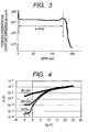
- the concentration of hydrogen atoms in the insulating layer produced by a sputtering step was measured. The result is shown in FIG. 3 . It can be seen from the result that the concentration of hydrogen atoms in the insulating layer (a-SiOx) prepared by the sputtering process is less than 3 ⁇ 10 21 atoms/cm 3 .
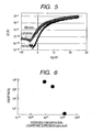
- FIG. 5 shows a change over time of a TFT using a gate insulating layer containing a small amount of hydrogen atoms (hydrogen content: less than 3 ⁇ 10 21 atoms/cm 3 ). In this case, little change was observed, and good characteristics were maintained.
- FIG. 6 shows a relationship between the concentration of hydrogen atoms in the gate insulating layer and an ON/OFF ratio of TFT characteristics at the time of 20 days after the preparation.
- the results mean that the TFT shows better characteristics when containing the hydrogen atom concentration to at least less than 3 ⁇ 10 21 atoms/cm 3 . This is considered to be because the resistance of the oxide semiconductor decreased due to the diffusion of hydrogen into the oxide semiconductor layer and a high ON/OFF ratio was not able to be attained, as is seen from the above described results.
- SiO x or SiN x is preferable for the gate insulating layer to be used in a thin film transistor using a transparent amorphous oxide film.
- the effect of the present invention is obtained as long as the hydrogen content in the insulating layer is less than 3 ⁇ 10 21 atoms/cm 3 , so that there is no lower limit in the hydrogen content in particular. Accordingly, the lower limit of the hydrogen content in the insulating layer is ideally zero.
- a leak current greatly differs depending on the type of a gate insulating film. Accordingly, a gate insulating film needs to be selected so as to match a channel layer.
- the gate insulating film and the channel layer can be formed at room temperature, so that any TFT structure of a staggered structure and an inverted staggered structure can be formed.
- the TFT is a three-terminal device having a gate terminal, a source terminal, and a drain terminal, and employs a semiconductor thin film formed on an insulation substrate such as of ceramic, glass or plastic as a channel layer through which electrons or holes move. Moreover, the TFT is also an active device which has a function of, in operation, applying a voltage to the gate terminal to control an electric current flowing in the channel layer, thereby switching an electric current between the source terminal and the drain terminal.
- the present embodiment relates to a display apparatus using the above described transparent amorphous oxide film.
- the embodiment relates to a display apparatus driven by TFTs each using a semiconductor which is the above described transparent amorphous oxide film, and in particular, relates to a light source and a display unit for emitting light by driving an organic EL device.
- the present embodiment can provide a display apparatus using a substrate even made of a plastic or the like which is lightweight and is hardly cracked.
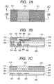
- FIGS. 7A, 7B and 7C a basic configuration of a display apparatus according to the present embodiment will be described with reference to FIGS. 7A, 7B and 7C .
- reference numeral 400 denotes a substrate
- reference numeral 401 denotes a power supply line
- reference numeral 402 denotes a GND (grounding) line
- reference numeral 403 denotes a signal electrode line
- reference numeral 404 denotes a first insulating layer (interlayer insulating layer)
- reference numeral 405 denotes a contact electrode embedded in each contact hole.
- reference numeral 406 denotes a gate electrode
- reference numeral 407 denotes a scanning electrode line
- reference numeral 408 denotes a second insulating layer
- reference numeral 409 denotes an amorphous oxide semiconductor
- reference numeral 410 denotes a source electrode and a drain electrode
- reference numeral 411 denotes a lower electrode
- reference numeral 412 denotes a third insulating layer
- reference numeral 413 denotes a light-emitting layer
- reference numeral 414 denotes an upper electrode.
- the second insulating layer 408 and the third insulating layer 412 together constitute the second insulating layer according to the present invention.
- the power supply line 401, the GND line 402, and the signal electrode line 403 are patterned on the substrate 400, and subsequently the first insulating layer 404 is deposited, contact holes are formed at desired positions of the first insulating layer 404, and the contact electrodes 405 are further embedded at the desired positions.
- the gate electrode 406 and the scanning electrode line 407 are patterned on the first insulating layer 404.
- the gate electrodes 406 are disposed in desired positions according to the necessary number of transistors, and electrodes (not shown) for the necessary number of capacitors are also patterned.
- the second insulating layer 408 having a hydrogen content of less than 3 ⁇ 10 21 atoms/cm 3 is formed by a sputtering step. Furthermore, contact holes are formed at desired positions of the second insulating layer 408, and contact electrodes are embedded in the contact holes.
- the lower electrode 411 of the light-emitting portion is formed so as to be connected to the power supply line 401 through the contact electrode 405, and an amorphous oxide semiconductor 409 is patterned on the second insulating layer 408. Subsequently, a source electrode and a drain electrode 410 are formed, and one of the electrodes is connected to a GND line 402 through the contact electrode.
- the third insulating layer 412 having a hydrogen content of less than 3 ⁇ 10 21 atoms/cm 3 is formed by a sputtering step.
- a light-emitting layer 413 composed of a hole-transporting layer, a light-emitting portion and an electron-transporting layer (not shown) is formed on the lower electrode 411.
- the upper electrode 414 is deposited on the light-emitting layer 413, and the upper electrode 414 is connected to the other electrode of the source electrode and the drain electrode 410.
- the light-emitting layer 413 is not limited to the above described configuration. Further, when the TFT is in an ON state, a voltage is applied to the light-emitting layer 413 to emit light.
- a metal electrode is used when the light-emitting device is used as a bottom emission type device, and a transparent electrode may be used when the light-emitting device is used as a two-sided emission type device. The material can be changed according to the intended use of the light-emitting device.
- a glass substrate is generally used in a image display apparatus.
- a substrate to be used in the present invention is not particularly limited as long as it has flatness. Since the TFT used in the present invention can be formed at a low temperature, a plastic substrate, which is generally hard to be used for an active matrix type display apparatus, can be used. Thereby, an image display apparatus is obtained which is lightweight and is hardly broken. The image display apparatus can be bent to a certain extent.
- a semiconductor substrate such as of Si or a ceramic substrate can also be used.
- a substrate having an insulating layer provided on a metal substrate can be used as long as it is flat.
- an In-Ga-Zn-O-based semiconductor is used as the active layer.
- substitution with or addition of an element such as Mg can be performed as long as the semiconductor has desired characteristics, that is, the electron carrier concentration is less than 10 18 /cm 3 and the electron mobility is more than 1 cm 2 /(V ⁇ sec).
- a sputtering process or a pulsed laser evaporation process is suitable for forming the active layer, but various sputtering processes which are advantageous in productivity are more preferable.
- it is effective to appropriately insert a buffer layer between the active layer and a substrate.
- the gate insulating film there are preferably used Al 2 O 3 , Y 2 O 3 , HfO 2 , SiO x , and SiNx as described above.
- the hydrogen content in the insulating layer is less than 3 ⁇ 10 21 atoms/cm 3 .
- the light-emitting layer is of a current injection type represented by an organic electroluminescent device
- a preferred electrode is adopted according to the configuration thereof.
- the lower electrode is preferably a transparent electrode having a large work function.
- examples of such material include ITO, electroconductive ZnO or In-Zn-O having an electron carrier concentration of 10 18 /cm 3 or more.
- ITO electroconductive ZnO or In-Zn-O having an electron carrier concentration of 10 18 /cm 3 or more.
- In-Ga-Zn-O-based oxide having an electron carrier concentration of 10 18 /cm 3 or more can be used as well.
- a larger carrier concentration for instance, 10 19 /cm 3 or more is more preferable.
- the light-emitting layer is not particularly limited as long as it can be driven by an In-Ga-Zn-O-based TFT, but is preferably an organic electroluminescent layer in particular.
- the light-emitting layer used in the present invention is generally composed of a plurality of layers such as
- a representative light-emitting layer is composed of hole-transporting layer/light-emitting section/electron-transporting layer.
- the light-emitting layer according to the present invention is not limited to these configurations.
- the light-emitting layer fluorescence and phosphorescence are utilized, but it is effective to utilize the phosphorescence from the viewpoint of emission efficiency.
- an iridium complex is useful.
- both a low molecular compound and a high molecular compound are available.
- the low molecular compound can be formed into a film by vapor deposition, and the high molecular compound can be formed into a film by ink jet or printing.
- the low molecular compound include an amine complex, an anthracene, a rare earth complex, and a noble metal complex.
- the high molecular compound include n-conjugated or pigment-containing polymers.
- an alkali metal As the material of the electron injection layer, there are included an alkali metal, an alkaline earth metal and a compound thereof; and an organic layer doped with an alkali metal.
- the material of the electron-transporting layer there are included an aluminium complex, oxadiazole, triazole, and phenanthroline.
- the material of the hole injection layer includes an arylamine, a phthalocyanine, and an organic layer doped with a Lewis acid.
- an arylamine is included.
- the preferred material of the upper electrode varies depending on whether the light emitting device is used as a two-sided emission type or a bottom emission type, and whether the upper electrode is used an anode or a cathode.
- the upper electrode When used as the two-sided emission type, the upper electrode needs to be transparent.
- the material of the transparent electrode includes oxides such as electroconductive ZnO, In-Zn-O, or ITO, which contains at least one element of In and Zn, is formed under deposition conditions including an oxygen flow rate adjusted such that the electron carrier concentration is 10 18 /cm 3 or more, and at least a part of which is amorphous.
- an In-Ga-Zn-O-based oxide having an electron carrier concentration of 10 18 /cm 3 or more can be used.
- the upper electrode can be prepared by forming an alloy doped with an alkali metal or an alkaline earth metal into a film of several 10 nm or less in thickness and forming a transparent electrode thereon.
- the upper electrode does not need to be transparent. Accordingly, when the upper electrode is used as the anode, the usable material includes an Au alloy or a Pt alloy having a large work function, and when used as the cathode, the usable material includes Ag-added Mg, Li-added Al, a silicide, a boride, and a nitride.
- a matrix wiring portion is formed beforehand (in which an interlayer insulating film used is normally a-SiOx:H, a-SiNx:H, a-SiNOx:H or the like produced by a PCVD (Plasma Chemical Vapor Deposition) process). Subsequently, an insulating layer is separately formed by using a method which is difficult to incorporate hydrogen into the insulating layer, and then an oxide semiconductor layer is formed and a pixel circuit is produced.
- an interlayer insulating film used is normally a-SiOx:H, a-SiNx:H, a-SiNOx:H or the like produced by a PCVD (Plasma Chemical Vapor Deposition) process.
- an insulating layer is separately formed by using a method which is difficult to incorporate hydrogen into the insulating layer, and then an oxide semiconductor layer is formed and a pixel circuit is produced.
- the display apparatus uses a TFT formed of or protected by the insulating layer having the small hydrogen content, and therefore can solve the problem that in the case where a conventional oxide semiconductor is used for a stacked device, when an insulating layer contains much hydrogen, the characteristics of the device are liable to be degraded due to the diffusion of the hydrogen.
- the present invention can provide a display apparatus which does not degrade the high mobility and excellent characteristics peculiar to the oxide semiconductor and is stably operated.
- reference numeral 55 denotes a selecting transistor which selects a pixel
- reference numeral 56 denotes a driving transistor which drives a light-emitting layer 58.
- a capacitor 57 is provided for keeping a selected state, stores an electric charge between a GND line 53 and a source electrode of the selecting transistor 55, and holds a signal of a gate of the driving transistor 56.
- the pixel is selected by a scanning electrode line 51 and a signal electrode line 52.
- An image signal from a driver circuit (not shown) is applied to a gate electrode in a form of a pulse signal through the scanning electrode line 51.
- another pulse signal from another driver circuit (not shown) is applied to the selecting transistor 55 through the signal electrode line 52, whereby a pixel is selected.
- the selecting transistor 55 is turned on, and an electric charge is stored in the capacitor 57 provided between the GND line 53 and the source of the selecting transistor 55.
- a gate voltage of the driving transistor 56 is kept at a desired voltage, and the driving transistor 56 is turned on. This state is maintained until a next signal is received. While the driving transistor 56 is in the ON state, a voltage and an electric current continue to be supplied to the light-emitting layer 58 to continue light emission.
- the example illustrated in FIG. 8 has the configuration in which one pixel has two transistors and one capacitor, but one pixel may have a larger number of transistors integrated therein in order to improve the performance. It is sufficient that an amorphous oxide semiconductor containing at least In and Zn is used in the portion of an active layer of a transistor and an insulating layer having a hydrogen content of less than 3 ⁇ 10 21 atoms/cm 3 . Further, it is preferred that a matrix wiring portion such as a scanning electrode line, a signal electrode line, and a power supply line is formed prior to the formation of the transistor portion. Thereby, an image display apparatus can be obtained which is excellent in long-term repetition characteristics.
- FIGS. 9A and 9B a basic configuration of a display apparatus according to another embodiment of the present invention will be described with reference to FIGS. 9A and 9B .
- reference numeral 600 denotes a substrate
- reference numeral 601 denotes a lower electrode
- reference numeral 602 denotes a power supply line
- reference numeral 603 denotes a signal electrode line
- reference numeral 604 denotes a GND line
- reference numeral 605 denotes a first insulating layer (interlayer insulating layer).
- reference numeral 606 denotes a gate electrode
- reference numeral 607 denotes a second insulating layer
- reference numeral 608 denotes an amorphous oxide semiconductor
- reference numeral 609 denotes a source electrode and a drain electrode
- reference numeral 610 denotes a third insulating layer
- reference numeral 611 denotes a bank
- reference numeral 612 denotes a light-emitting layer
- reference numeral 613 denotes an upper electrode.
- the second insulating layer 607 and the third insulating layer 610 together constitute the second insulating layer according to the present invention.
- the lower electrode 601 of the light-emitting layer 612 is patterned on the substrate 600. Furthermore, after a metal layer is deposited, the power supply line 602, the signal electrode line 603, and the GND line 604 are also patterned. At this time, the power supply line 602 is patterned so as to be in contact with the lower electrode 601.
- the gate electrode 606 and a scanning electrode line are patterned at desired positions on the first insulating layer 605.
- the gate electrodes 606 are disposed corresponding to the necessary number of transistors, and electrodes (not shown) for the necessary number of capacitors are also patterned.
- the matrix wiring portion is formed before the formation of the transistor.
- the second insulating layer 607 having a hydrogen content of less than 3 ⁇ 10 21 atoms/cm 3 is formed thereon. Furthermore, a contact hole is formed at a desired position of the second insulating layer 607, and a contact electrode is embedded in the contact hole. In addition, an amorphous oxide semiconductor 608 which becomes an active layer of the transistor is patterned on the second insulating layer 607. Subsequently, the source electrode and drain electrode 609 are formed, and one of the electrodes is connected to the GND line 604 through the contact electrode.
- the third insulating layer 610 having a hydrogen content of less than 3 ⁇ 10 21 atoms/cm 3 is formed thereon with a sputtering step so as to protect the channel portion of the transistor.
- the light-emitting layer 612 is formed which is composed of a hole-transporting layer, a light-emitting portion, an electron-transporting layer and the like (not shown).
- the upper electrode 613 is deposited, and the thus formed upper electrode 613 is connected to the other of the source electrode and drain electrode 609.
- the light-emitting layer 612 is not limited to the above described configuration. Further, when the TFT is in an ON state, a voltage is applied to the light-emitting layer 612 to emit light.
- a metal electrode is used when the light-emitting device is used as a bottom emission type device, and a transparent electrode may be used when the light-emitting device is used as a two-sided emission type device. The material can be changed according to the intended use of the light-emitting device.
- Example 1 according to the present invention will now be described.
- a SiO 2 glass substrate (1737 manufactured by Corning, Inc.) was prepared as a substrate for film formation.
- the substrate was ultrasonically degreased and cleaned with acetone, IPA (isopropanol), and ultrapure water sequentially for five minutes each and then dried at 100°C in air.
- a film with a thickness of 200 nm was deposited by a DC (direct current) sputtering process using Al-Si (5%) as a target material, and then a power supply line, a GND line, and a signal electrode line were patterned at desired positions by using a photolithographic process and a dry process.
- a film of a-SiNx:H was deposited thereon as an interlayer insulating layer in a thickness of 600 nm at a substrate temperature of 300°C using a plasma-CVD process.
- contact holes were formed in desired positions, and electrodes were embedded so as to contact the power supply line, the GND line, and the signal electrode line.
- films of Ti/Au/Ti were deposited in thicknesses of 5 nm/40 nm/5 nm respectively with a DC sputtering process using Au and Ti as target materials.
- a scanning electrode line, two gate electrodes for TFT and an electrode for a capacitor were formed at desired positions with a photolithographic process and a lift-off process.
- a matrix wiring portion was formed on the substrate, and then the gate electrode for the TFT and the electrode for the capacitor were formed thereon.
- a second insulating layer having a hydrogen content of less than 3 ⁇ 10 21 atoms/cm 3 was formed on the substrate having the matrix wiring portion formed thereon.
- a sintered body (with a size of 98 mm in diameter and 5 mm in thickness) having a composition of SiO 2 was used for the target material.
- a deposition chamber was controlled to reach a vacuum degree of 2.0 ⁇ 10 -4 Pa.
- Ar gas was flown at 133 Pa for 20 minutes before the film formation, and pre-sputtering was performed for five minutes.
- the total pressure in the chamber was controlled to a constant value of 0.1 Pa, Ar gas was flown at 10 seem, and the distance between the target and the film-forming substrate was set at 75 mm.
- the input power was RF 400 W, and the film forming rate was 7 nm/min.
- the deposited film thickness of the second insulating layer was 200 nm.
- contact holes were formed in the second insulating layer with a dry etching process. The dry etching was performed under the conditions of CF 4 gas 20 sccm, 5 Pa, and RF 150 W at an etch rate of 41 nm/min for 5.5 minutes.
- an amorphous oxide semiconductor was formed as the active layer of the TFT.
- a polycrystal sintered body (with a size of 98 mm in diameter and 5 mm in thickness) having the composition of InGaO 3 (ZnO) 4 was used for the target material.
- the sintered body was prepared by dry mixing In 2 O3, Ga 2 O 3 and ZnO (each 4N reagent) as starting materials (solvent: ethanol), followed by presintering (1,000°C; 2 hours), dry milling, and sintering (1,500°C; 2 hours).
- the target had an electrical conductivity of 12 S/cm and was in a semi-insulating state.
- the vacuum reached in the deposition chamber was 3.0 ⁇ 10 -4 Pa.
- the total pressure in the deposition chamber was controlled to a constant value of 0.5 Pa, and the oxygen gas ratio was controlled to 5%.
- the distance between the target and the film-forming substrate was set at 75 mm.
- the input power was RF 200 W, and the film-forming rate was set at 7.1 nm/min.
- the deposited film thickness of the amorphous oxide semiconductor was 40 nm.
- a source electrode and a drain electrode of a TFT and a lower electrode of a light-emitting layer were prepared.
- a sintered body (with a size of 98 mm in diameter and 5 mm in thickness) having a composition of ITO (Sn: 5%) was used as a target material.
- the vacuum reached in the deposition chamber was 3.0 ⁇ 10 -4 Pa.
- Ar gas was flown at 10 sccm, and the distance between the target and the film-forming substrate was set at 75 mm.
- the input electric power was RF 300 W, and the film-forming rate was set at 60 nm/min.
- the film thickness was 100 nm.
- the source electrode, the drain electrode, and the lower electrode of the light-emitting layer were formed by patterning at desired positions with a photolithographic process and a lift-off process.
- a film of SiO x with a thickness of 200 nm was stacked using a sputtering process by following the same procedure as the formation of the second insulating layer, and a third insulating layer was formed by patterning at desired positions by means of a photolithographic process and a lift-off process.
- a light-emitting layer was formed on the lower electrode for the light-emitting layer.
- a hole injection layer was formed of 4,4'-bis[N, N-diamino]-4"-phenyl-triphenylamine in a thickness of 45 nm by using a resistive evaporation process. Then, a film of 4,4'-bis[N-(1-naphthyl)-N-phenylamino]biphenyl was formed thereon in a thickness of 25 nm as a hole-transporting layer.
- a film of 4,4'-bis(2,2'-diphenyl vinyl)-1,1'-biphenyl as a light-emitting layer was formed thereon in a thickness of 30 nm and a film of tris(8-quinolinol) aluminum as an electron-transporting layer was further formed thereon in a thickness of 15 nm, thus completing an organic EL light-emitting layer as a whole.
- an upper electrode of the light-emitting layer was prepared by forming a film of an alloy of Al and Ag in a thickness of 50 nm with a resistive heating evaporation process, and forming an Al film thereon in a thickness of 200 nm.
- the upper electrode was connected to the drain electrode of the TFT.
- the substrate having the films stacked thereon was sealed with a glass cap containing a desiccant (not shown), whereby a display apparatus having basically the same configuration as that shown in FIGS. 7A to 7C was produced.
- a display apparatus was made by following the same procedure as Example 1 with the exception that the second insulating layer having a hydrogen content of less than 3 ⁇ 10 21 atoms/cm 3 was not used and an interlayer insulating layer was used as a gate insulating layer of the TFT. While the TFTs were operated, the operation was gradually deviated from a normal operation. In the normal operation, an electric charge should be retained and light emission should be observed, while with the display apparatus of the present comparative example, a leak current increased with the lapse of time and the light emission became intermittent.
- Example 2 according to the present invention will be described.
- a SiO 2 glass substrate (1737 manufacture by Corning Inc.) which had an ITO film with a resistivity of 1.4 ⁇ 10 -4 ⁇ cm and a thickness of 100 nm formed thereon.
- the substrate was ultrasonically degreased and cleaned with acetone, IPA, and ultrapure water sequentially for five minutes each and then dried at 100°C in air.
- a lower electrode of a light-emitting layer was patterned by a photolithographic process and a wet process.
- a film with a thickness of 200 nm was deposited by a DC sputtering process using Al-Si (5%) as a target material, and then a power supply line, a GND line, and a signal electrode line were patterned at desired positions by using a photolithographic process and a dry process. At this time, patterning was performed such that the lower electrode and the power supply line were in contact with each other.
- a film of a-SiNx:H was deposited thereon as an interlayer insulating layer in a thickness of 700 nm at a substrate temperature of 250°C using a plasma-CVD process. Subsequently, contact holes were formed in desired positions, and electrodes were embedded so as to contact the GND line, and the signal electrode line.
- films of Ti/Au/Ti were deposited in thicknesses of 5 nm/40 nm/5 nm respectively with a DC sputtering process using Au and Ti as target materials, and a scanning electrode line, two gate electrodes and an electrode for a capacitor were formed at desired positions with a photolithographic process and a lift-off process.
- a matrix wiring portion and a lower electrode for a light-emitting layer were formed on the substrate, and then the gate electrode for the TFT and the electrode for the capacitor were formed thereon.
- a second insulating layer having a hydrogen content of less than 3 ⁇ 10 21 atoms/cm 3 was formed on the substrate having the matrix wiring portion formed thereon.
- a sintered body (with a size of 98 mm in diameter and 5 mm in thickness) having a composition of SiO 2 was used for the target material.
- a deposition chamber was controlled to reach a vacuum degree of 2.0 ⁇ 10 -4 Pa.
- Ar gas was flown at 133 Pa for 25 minutes before the film formation, and pre-sputtering was performed for five minutes.
- the total pressure in the chamber was controlled to a constant value of 0.1 Pa, Ar gas was flown at 10 seem, and the distance between the target and the film-forming substrate was set at 75 mm.
- the input power was RF 400 W, and the film forming rate was 7 nm/min.
- the deposited film thickness of the second insulating layer was 220 nm.
- contact holes were formed in the second insulating layer with a dry etching process. The dry etching was performed under the conditions of CF 4 gas 20 sccm, 5 Pa, and RF 150 W at an etch rate of 41 nm/min for 6.0 minutes.
- an amorphous oxide semiconductor was formed as the active layer of the TFT.
- a polycrystal sintered body (with a size of 98 mm in diameter and 5 mm in thickness) having the composition of InGaO 3 (ZnO) 4 was used for the target material.
- the sintered body was prepared by dry mixing In 2 O 3 , Ga 2 O 3 and ZnO (each 4N reagent) as starting materials (solvent: ethanol), followed by presintering (1,000°C; 2 hours), dry milling, and sintering (1,500°C; 2 hours).
- the target had an electrical conductivity of 12 S/cm and was in a semi-insulating state.
- the vacuum reached in the deposition chamber was 3.0 ⁇ 10 -4 Pa.
- the total pressure in the deposition chamber was controlled to a constant value of 0.5 Pa, and the oxygen gas ratio was controlled to 5.5%.
- the distance between the target and the film-forming substrate was set at 75 mm.
- the input power was RF 200 W, and the film-forming rate was set at 7.1 nm/min.
- the deposited film thickness of the amorphous oxide semiconductor was 35 nm.
- a source electrode and a drain electrode of the TFT were prepared.
- Au and Ti were used as target materials and films of Ti/Au/Ti were deposited in thicknesses of 5 nm/40 nm/5 nm respectively with a DC sputtering process, and the source electrode and the drain electrode were formed at desired positions with a photolithographic process and a lift-off process.
- a film of SiO x with a thickness of 300 nm was stacked using a sputtering process by following the same procedure as the formation of the second insulating layer, and a third insulating layer was formed by patterning at desired positions by means of a photolithographic process and a lift-off process.
- a light-emitting layer was formed on the lower electrode for the light-emitting layer.
- a hole injection layer was formed of 4,4'-bis[N, N-diamino]-4"-phenyl-triphenylamine in a thickness of 45 nm by using a resistive evaporation process. Then, a film of 4,4'-bis[N-(1-naphthyl)-N-phenylamino]biphenyl was formed thereon in a thickness of 25 nm as a hole-transporting layer.
- a film of 4,4'-bis(2,2'-diphenyl vinyl)-1,1'-biphenyl as a light-emitting layer was formed thereon in a thickness of 30 nm and a film of tris(8-quinolinol) aluminum as an electron-transporting layer was further formed thereon in a thickness of 15 nm, thus completing an organic EL light-emitting layer as a whole.
- an upper electrode of the light-emitting layer was prepared by forming a film of an alloy of Al and Ag in a thickness of 50 nm with a resistive heating evaporation process, and forming an Al film thereon in a thickness of 200 nm.
- the upper electrode was connected to the drain electrode of the TFT.
- the substrate having the films stacked thereon was sealed with a glass cap containing a desiccant (not shown), whereby a display apparatus having basically the same configuration as that shown in FIGS. 9A and 9B was produced.
- a display apparatus was made by following the same procedure as Example 2 with the exception that the second insulating layer having a hydrogen content of less than 3 ⁇ 10 21 atoms/cm 3 was not used and an interlayer insulating layer was used as a gate insulating layer of the TFT.
- the TFTs were operated, an electric charge was held and light emission was observed. However, with the lapse of time, a leak current gradually increased and the light emission became intermittent.
- Example 3 according to the present invention will be described.
- a display apparatus was made by following the same procedure as in Example 1 up to the completion of the matrix wiring portion.
- a second insulating layer having a hydrogen content of less than 3 ⁇ 10 21 atoms/cm 3 was formed on the substrate having the matrix wiring portion formed thereon.
- a sintered body (with a size of 98 mm in diameter and 5 mm in thickness) having a composition of Si 3 N 4 was used for the target material.
- a deposition chamber was controlled to reach a vacuum degree of 2.5 ⁇ 10 -4 Pa.
- Ar gas was flown at 133 Pa for 20 minutes before the film formation, and pre-sputtering was performed for five minutes.
- the total pressure in the chamber was controlled to a constant value of 0.1 Pa, Ar gas was flown at 15 seem, and the distance between the target and the film-forming substrate was set at 75 mm.
- the input power was RF 400 W, and the film forming rate was 6 nm/min.
- the deposited film thickness of the second insulating layer was 200 nm.
- contact holes were formed in the second insulating layer with a dry etching process. The dry etching was performed under the conditions of CF 4 gas 20 seem, 5 Pa, and RF 160 W at an etch rate of 41 nm/min for 7 minutes.
- an amorphous oxide semiconductor was formed as the active layer of the TFT.
- a polycrystal sintered body (with a size of 98 mm in diameter and 5 mm in thickness) having the composition of InGaO 3 (ZnO) 4 was used for the target material.
- the sintered body was prepared by dry mixing In 2 O 3 , Ga 2 O 3 and ZnO (each 4N reagent) as starting materials (solvent: ethanol), followed by presintering (1,000°C; 2 hours), dry milling, and sintering (1,500°C; 2 hours).
- the target had an electrical conductivity of 12 S/cm and was in a semi-insulating state.
- the vacuum reached in the deposition chamber was 3.0 ⁇ 10 -4 Pa.
- the total pressure in the deposition chamber was controlled to a constant value of 0.5 Pa, and the oxygen gas ratio was controlled to 5%.
- the distance between the target and the film-forming substrate was set at 75 mm.
- the input power was RF 200 W, and the film-forming rate was set at 7.1 nm/min.
- the deposited film thickness of the amorphous oxide semiconductor was 30 nm.
- Example 1 a display apparatus having basically the same configuration as that shown in FIGS. 7A to 7C was produced.
- Example 4 according to the present invention will be described.
- a display apparatus was made by following the same procedure as in Example 2 up to the completion of the matrix wiring portion.
- a second insulating layer having a hydrogen content of less than 3 ⁇ 10 21 atoms/cm 3 was formed on the substrate having the matrix wiring portion formed thereon.
- a sintered body (with a size of 98 mm in diameter and 5 mm in thickness) having a composition of Si 3 N 4 was used for the target material.
- a deposition chamber was controlled to reach a vacuum degree of 2.5 ⁇ 10 -4 Pa. In the deposition chamber, Ar gas was flown at 133 Pa for 20 minutes before the film formation, and pre-sputtering was performed for five minutes.
- the total pressure in the chamber was controlled to a constant value of 0.1 Pa, Ar gas was flown at 20 seem, O 2 gas was flown at 3 seem, and the distance between the target and the film-forming substrate was set at 75 mm.
- the input power was RF 420 W, and the film forming rate was 6 nm/min.
- the deposited film thickness of the second insulating layer was 200 nm.
- contact holes were formed in the second insulating layer with a dry etching process. The dry etching was performed under the conditions of CF 4 gas 20 seem, 5 Pa, and RF 180 W at an etch rate of 32 nm/min for 7 minutes.
- an amorphous oxide semiconductor was formed as the active layer of the TFT.
- a polycrystal sintered body (with a size of 98 mm in diameter and 5 mm in thickness) having the composition of InGaO 3 (ZnO) 4 was used for the target material.
- the sintered body was prepared by dry mixing In 2 O 3 , Ga 2 O 3 and ZnO (each 4N reagent) as starting materials (solvent: ethanol), followed by presintering (1,000°C; 2 hours), dry milling, and sintering (1,500°C; 2 hours).
- the target had an electrical conductivity of 12 S/cm and was in a semi-insulating state.
- the vacuum reached in the deposition chamber was 3.0 ⁇ 10 -4 Pa.
- the total pressure in the deposition chamber was controlled to a constant value of 0.5 Pa, and the oxygen gas ratio was controlled to 5.5%.
- the distance between the target and the film-forming substrate was set at 75 mm.
- the input power was RF 220 W, and the film-forming rate was set at 7.1 nm/min.
- the deposited film thickness of the amorphous oxide semiconductor was 30 nm.
- Example 2 a display apparatus having basically the same configuration as that shown in FIGS. 9A and 9B was produced.
Landscapes
- Engineering & Computer Science (AREA)
- Microelectronics & Electronic Packaging (AREA)
- Physics & Mathematics (AREA)
- Geometry (AREA)
- Thin Film Transistor (AREA)
- Electroluminescent Light Sources (AREA)
- Devices For Indicating Variable Information By Combining Individual Elements (AREA)
- Shift Register Type Memory (AREA)
Applications Claiming Priority (3)
| Application Number | Priority Date | Filing Date | Title |
|---|---|---|---|
| JP2006328307A JP5105842B2 (ja) | 2006-12-05 | 2006-12-05 | 酸化物半導体を用いた表示装置及びその製造方法 |
| EP07850227.5A EP2084746B1 (en) | 2006-12-05 | 2007-11-30 | Display apparatus using oxide semiconductor and production method thereof |
| PCT/JP2007/073619 WO2008069286A2 (en) | 2006-12-05 | 2007-11-30 | Display apparatus using oxide semiconductor and production method thereof |
Related Parent Applications (2)
| Application Number | Title | Priority Date | Filing Date |
|---|---|---|---|
| EP07850227.5A Division EP2084746B1 (en) | 2006-12-05 | 2007-11-30 | Display apparatus using oxide semiconductor and production method thereof |
| EP07850227.5A Division-Into EP2084746B1 (en) | 2006-12-05 | 2007-11-30 | Display apparatus using oxide semiconductor and production method thereof |
Publications (2)
| Publication Number | Publication Date |
|---|---|
| EP3249694A1 EP3249694A1 (en) | 2017-11-29 |
| EP3249694B1 true EP3249694B1 (en) | 2020-02-26 |
Family
ID=39110785
Family Applications (2)
| Application Number | Title | Priority Date | Filing Date |
|---|---|---|---|
| EP17000733.0A Active EP3249694B1 (en) | 2006-12-05 | 2007-11-30 | Field effect transistor using oxide semiconductor and display apparatus therewith |
| EP07850227.5A Active EP2084746B1 (en) | 2006-12-05 | 2007-11-30 | Display apparatus using oxide semiconductor and production method thereof |
Family Applications After (1)
| Application Number | Title | Priority Date | Filing Date |
|---|---|---|---|
| EP07850227.5A Active EP2084746B1 (en) | 2006-12-05 | 2007-11-30 | Display apparatus using oxide semiconductor and production method thereof |
Country Status (7)
Families Citing this family (83)
| Publication number | Priority date | Publication date | Assignee | Title |
|---|---|---|---|---|
| EP2453480A2 (en) * | 2004-11-10 | 2012-05-16 | Canon Kabushiki Kaisha | Amorphous oxide and field effect transistor |
| JP5213422B2 (ja) * | 2007-12-04 | 2013-06-19 | キヤノン株式会社 | 絶縁層を有する酸化物半導体素子およびそれを用いた表示装置 |
| KR100963026B1 (ko) | 2008-06-30 | 2010-06-10 | 삼성모바일디스플레이주식회사 | 박막 트랜지스터, 그의 제조 방법 및 박막 트랜지스터를구비하는 평판 표시 장치 |
| KR100963027B1 (ko) | 2008-06-30 | 2010-06-10 | 삼성모바일디스플레이주식회사 | 박막 트랜지스터, 그의 제조 방법 및 박막 트랜지스터를구비하는 평판 표시 장치 |
| KR102026604B1 (ko) * | 2008-07-10 | 2019-10-01 | 가부시키가이샤 한도오따이 에네루기 켄큐쇼 | 발광 장치 및 전자 기기 |
| US8129718B2 (en) | 2008-08-28 | 2012-03-06 | Canon Kabushiki Kaisha | Amorphous oxide semiconductor and thin film transistor using the same |
| US9082857B2 (en) * | 2008-09-01 | 2015-07-14 | Semiconductor Energy Laboratory Co., Ltd. | Semiconductor device comprising an oxide semiconductor layer |
| JP5627071B2 (ja) | 2008-09-01 | 2014-11-19 | 株式会社半導体エネルギー研究所 | 半導体装置の作製方法 |
| KR20160063402A (ko) | 2008-09-12 | 2016-06-03 | 가부시키가이샤 한도오따이 에네루기 켄큐쇼 | 디스플레이 장치 |
| JP5616012B2 (ja) | 2008-10-24 | 2014-10-29 | 株式会社半導体エネルギー研究所 | 半導体装置の作製方法 |
| JP5491833B2 (ja) * | 2008-12-05 | 2014-05-14 | 株式会社半導体エネルギー研究所 | 半導体装置 |
| EP2515337B1 (en) | 2008-12-24 | 2016-02-24 | Semiconductor Energy Laboratory Co., Ltd. | Driver circuit and semiconductor device |
| DE102009007947B4 (de) | 2009-02-06 | 2014-08-14 | Universität Stuttgart | Verfahren zur Herstellung eines Aktiv-Matrix-OLED-Displays |
| US20100224880A1 (en) * | 2009-03-05 | 2010-09-09 | Semiconductor Energy Laboratory Co., Ltd. | Semiconductor device |
| KR102195170B1 (ko) * | 2009-03-12 | 2020-12-24 | 가부시키가이샤 한도오따이 에네루기 켄큐쇼 | 반도체 장치 |
| KR20200031709A (ko) | 2009-06-30 | 2020-03-24 | 가부시키가이샤 한도오따이 에네루기 켄큐쇼 | 반도체 장치 제조 방법 |
| KR101342179B1 (ko) * | 2009-09-24 | 2013-12-16 | 가부시키가이샤 한도오따이 에네루기 켄큐쇼 | 반도체 소자 및 그 제조 방법 |
| WO2011043163A1 (en) | 2009-10-05 | 2011-04-14 | Semiconductor Energy Laboratory Co., Ltd. | Semiconductor device and manufacturing method thereof |
| CN102687204A (zh) * | 2009-10-09 | 2012-09-19 | 株式会社半导体能源研究所 | 移位寄存器和显示装置以及其驱动方法 |
| WO2011043206A1 (en) | 2009-10-09 | 2011-04-14 | Semiconductor Energy Laboratory Co., Ltd. | Semiconductor device |
| CN116343705B (zh) | 2009-10-16 | 2025-08-26 | 株式会社半导体能源研究所 | 显示设备 |
| KR101291488B1 (ko) | 2009-10-21 | 2013-07-31 | 가부시키가이샤 한도오따이 에네루기 켄큐쇼 | 반도체 장치 |
| SG10201406934WA (en) * | 2009-10-29 | 2014-11-27 | Semiconductor Energy Lab | Semiconductor device |
| SG10201406869QA (en) * | 2009-10-29 | 2014-12-30 | Semiconductor Energy Lab | Semiconductor device |
| KR20120102653A (ko) | 2009-10-30 | 2012-09-18 | 가부시키가이샤 한도오따이 에네루기 켄큐쇼 | 반도체 장치 및 반도체 장치의 제작방법 |
| WO2011052437A1 (en) | 2009-10-30 | 2011-05-05 | Semiconductor Energy Laboratory Co., Ltd. | Non-linear element, display device including non-linear element, and electronic device including display device |
| CN104485341A (zh) | 2009-11-06 | 2015-04-01 | 株式会社半导体能源研究所 | 半导体装置 |
| WO2011058885A1 (en) * | 2009-11-13 | 2011-05-19 | Semiconductor Energy Laboratory Co., Ltd. | Display device and electronic device including the same |
| CN102668097B (zh) | 2009-11-13 | 2015-08-12 | 株式会社半导体能源研究所 | 半导体器件及其制造方法 |
| WO2011065209A1 (en) * | 2009-11-27 | 2011-06-03 | Semiconductor Energy Laboratory Co., Ltd. | Non-linear element, display device including non-linear element, and electronic device including display device |
| KR102304078B1 (ko) | 2009-11-28 | 2021-09-23 | 가부시키가이샤 한도오따이 에네루기 켄큐쇼 | 반도체 장치 및 그 제조 방법 |
| WO2011068106A1 (en) * | 2009-12-04 | 2011-06-09 | Semiconductor Energy Laboratory Co., Ltd. | Display device and electronic device including the same |
| KR101523358B1 (ko) * | 2009-12-04 | 2015-05-27 | 가부시키가이샤 한도오따이 에네루기 켄큐쇼 | 표시 장치 |
| CN102640272B (zh) | 2009-12-04 | 2015-05-20 | 株式会社半导体能源研究所 | 半导体装置及其制造方法 |
| CN102640207A (zh) | 2009-12-18 | 2012-08-15 | 株式会社半导体能源研究所 | 液晶显示装置及其驱动方法 |
| KR20200013808A (ko) * | 2009-12-25 | 2020-02-07 | 가부시키가이샤 한도오따이 에네루기 켄큐쇼 | 메모리 장치, 반도체 장치, 및 전자 장치 |
| KR101698537B1 (ko) * | 2010-01-15 | 2017-01-20 | 가부시키가이샤 한도오따이 에네루기 켄큐쇼 | 반도체 장치 |
| KR102237655B1 (ko) * | 2010-01-15 | 2021-04-09 | 가부시키가이샤 한도오따이 에네루기 켄큐쇼 | 반도체 장치 및 이를 구동하는 방법 |
| WO2011086871A1 (en) * | 2010-01-15 | 2011-07-21 | Semiconductor Energy Laboratory Co., Ltd. | Semiconductor device |
| US8617920B2 (en) * | 2010-02-12 | 2013-12-31 | Semiconductor Energy Laboratory Co., Ltd. | Semiconductor device and manufacturing method thereof |
| EP2365417A3 (en) * | 2010-03-08 | 2015-04-29 | Semiconductor Energy Laboratory Co, Ltd. | Electronic device and electronic system |
| WO2011114905A1 (en) * | 2010-03-19 | 2011-09-22 | Semiconductor Energy Laboratory Co., Ltd. | Semiconductor memory device |
| WO2011118741A1 (en) * | 2010-03-26 | 2011-09-29 | Semiconductor Energy Laboratory Co., Ltd. | Method for manufacturing semiconductor device |
| CN102822980B (zh) * | 2010-03-26 | 2015-12-16 | 株式会社半导体能源研究所 | 半导体装置的制造方法 |
| KR20180082636A (ko) * | 2010-04-28 | 2018-07-18 | 가부시키가이샤 한도오따이 에네루기 켄큐쇼 | 표시 장치 |
| WO2011145484A1 (en) | 2010-05-21 | 2011-11-24 | Semiconductor Energy Laboratory Co., Ltd. | Semiconductor device |
| WO2011145467A1 (en) | 2010-05-21 | 2011-11-24 | Semiconductor Energy Laboratory Co., Ltd. | Semiconductor device |
| JP2011249674A (ja) * | 2010-05-28 | 2011-12-08 | Fujifilm Corp | 薄膜トランジスタおよびその製造方法 |
| KR101319200B1 (ko) * | 2010-06-01 | 2013-10-16 | 샤프 가부시키가이샤 | 박막 트랜지스터 |
| JP5771079B2 (ja) * | 2010-07-01 | 2015-08-26 | 株式会社半導体エネルギー研究所 | 撮像装置 |
| KR101885691B1 (ko) * | 2010-07-27 | 2018-08-06 | 가부시키가이샤 한도오따이 에네루기 켄큐쇼 | 반도체 장치 및 그 제작 방법 |
| US8592261B2 (en) * | 2010-08-27 | 2013-11-26 | Semiconductor Energy Laboratory Co., Ltd. | Method for designing semiconductor device |
| KR101891841B1 (ko) * | 2010-09-28 | 2018-08-24 | 도판 인사츠 가부시키가이샤 | 박막 트랜지스터 및 그의 제조 방법, 박막 트랜지스터를 구비하는 화상 표시 장치 |
| JP5647860B2 (ja) * | 2010-10-28 | 2015-01-07 | 富士フイルム株式会社 | 薄膜トランジスタおよびその製造方法 |
| TWI593115B (zh) | 2010-11-11 | 2017-07-21 | 半導體能源研究所股份有限公司 | 半導體裝置及其製造方法 |
| JP6035007B2 (ja) * | 2010-12-10 | 2016-11-30 | 富士通株式会社 | Mis型の窒化物半導体hemt及びその製造方法 |
| KR101832361B1 (ko) * | 2011-01-19 | 2018-04-16 | 삼성디스플레이 주식회사 | 박막 트랜지스터 표시판 및 그 제조 방법 |
| KR101995682B1 (ko) | 2011-03-18 | 2019-07-02 | 가부시키가이샤 한도오따이 에네루기 켄큐쇼 | 산화물 반도체막, 반도체 장치, 및 반도체 장치의 제작 방법 |
| TWI545652B (zh) | 2011-03-25 | 2016-08-11 | 半導體能源研究所股份有限公司 | 半導體裝置及其製造方法 |
| US8956944B2 (en) | 2011-03-25 | 2015-02-17 | Semiconductor Energy Laboratory Co., Ltd. | Semiconductor device and method for manufacturing the same |
| US9219159B2 (en) * | 2011-03-25 | 2015-12-22 | Semiconductor Energy Laboratory Co., Ltd. | Method for forming oxide semiconductor film and method for manufacturing semiconductor device |
| US9012904B2 (en) | 2011-03-25 | 2015-04-21 | Semiconductor Energy Laboratory Co., Ltd. | Semiconductor device and method for manufacturing the same |
| KR101922397B1 (ko) * | 2011-05-20 | 2018-11-28 | 가부시키가이샤 한도오따이 에네루기 켄큐쇼 | 반도체 장치 |
| US9130044B2 (en) | 2011-07-01 | 2015-09-08 | Semiconductor Energy Laboratory Co., Ltd. | Semiconductor device and manufacturing method thereof |
| JP5740270B2 (ja) * | 2011-09-27 | 2015-06-24 | 株式会社東芝 | 薄膜トランジスタ、その製造方法、および表示装置 |
| WO2013052298A1 (en) * | 2011-10-07 | 2013-04-11 | Applied Materials, Inc. | Methods for depositing a silicon containing layer with argon gas dilution |
| WO2013089115A1 (en) | 2011-12-15 | 2013-06-20 | Semiconductor Energy Laboratory Co., Ltd. | Semiconductor device and method for manufacturing the same |
| TWI584383B (zh) | 2011-12-27 | 2017-05-21 | 半導體能源研究所股份有限公司 | 半導體裝置及其製造方法 |
| JP5687638B2 (ja) * | 2012-01-26 | 2015-03-18 | 株式会社東芝 | 表示装置の製造方法 |
| TWI596778B (zh) * | 2012-06-29 | 2017-08-21 | 半導體能源研究所股份有限公司 | 半導體裝置及半導體裝置的製造方法 |
| US20140014948A1 (en) * | 2012-07-12 | 2014-01-16 | Semiconductor Energy Laboratory Co. Ltd. | Semiconductor device |
| KR102022886B1 (ko) * | 2012-12-28 | 2019-09-19 | 엘지디스플레이 주식회사 | 유기발광장치 |
| US8981374B2 (en) | 2013-01-30 | 2015-03-17 | Semiconductor Energy Laboratory Co., Ltd. | Semiconductor device |
| JP6475424B2 (ja) | 2013-06-05 | 2019-02-27 | 株式会社半導体エネルギー研究所 | 半導体装置 |
| JP2015036797A (ja) | 2013-08-15 | 2015-02-23 | ソニー株式会社 | 表示装置および電子機器 |
| JP5770236B2 (ja) * | 2013-09-18 | 2015-08-26 | 株式会社ジャパンディスプレイ | 表示装置 |
| KR102748398B1 (ko) | 2014-03-13 | 2025-01-03 | 가부시키가이샤 한도오따이 에네루기 켄큐쇼 | 촬상 장치 |
| KR102380829B1 (ko) | 2014-04-23 | 2022-03-31 | 가부시키가이샤 한도오따이 에네루기 켄큐쇼 | 촬상 장치 |
| JP6611521B2 (ja) * | 2015-08-25 | 2019-11-27 | 三菱電機株式会社 | 薄膜トランジスタ及びアレイ基板 |
| WO2017115208A1 (en) | 2015-12-28 | 2017-07-06 | Semiconductor Energy Laboratory Co., Ltd. | Device, television system, and electronic device |
| CN113948623B (zh) | 2016-01-13 | 2024-11-19 | 首尔伟傲世有限公司 | 发光元件 |
| KR102624111B1 (ko) * | 2016-01-13 | 2024-01-12 | 서울바이오시스 주식회사 | 자외선 발광소자 |
| JP6715312B2 (ja) * | 2018-12-04 | 2020-07-01 | 三星ディスプレイ株式會社Samsung Display Co.,Ltd. | 表示装置 |
Family Cites Families (25)
| Publication number | Priority date | Publication date | Assignee | Title |
|---|---|---|---|---|
| JP3179287B2 (ja) | 1993-12-28 | 2001-06-25 | 出光興産株式会社 | 導電性透明基材およびその製造方法 |
| JPH09114398A (ja) | 1995-10-24 | 1997-05-02 | Idemitsu Kosan Co Ltd | 有機elディスプレイ |
| JP4170454B2 (ja) | 1998-07-24 | 2008-10-22 | Hoya株式会社 | 透明導電性酸化物薄膜を有する物品及びその製造方法 |
| US6559594B2 (en) * | 2000-02-03 | 2003-05-06 | Semiconductor Energy Laboratory Co., Ltd. | Light-emitting device |
| JP4089858B2 (ja) | 2000-09-01 | 2008-05-28 | 国立大学法人東北大学 | 半導体デバイス |
| TWI247182B (en) * | 2000-09-29 | 2006-01-11 | Toshiba Corp | Flat panel display device and method for manufacturing the same |
| US7042024B2 (en) * | 2001-11-09 | 2006-05-09 | Semiconductor Energy Laboratory Co., Ltd. | Light emitting apparatus and method for manufacturing the same |
| US6903377B2 (en) * | 2001-11-09 | 2005-06-07 | Semiconductor Energy Laboratory Co., Ltd. | Light emitting apparatus and method for manufacturing the same |
| CN1499643A (zh) * | 2002-11-11 | 2004-05-26 | 友达光电股份有限公司 | 主动式有机发光显示器及其制造方法 |
| US7381579B2 (en) * | 2004-02-26 | 2008-06-03 | Samsung Sdi Co., Ltd. | Donor sheet, method of manufacturing the same, method of manufacturing TFT using the donor sheet, and method of manufacturing flat panel display device using the donor sheet |
| US7125758B2 (en) | 2004-04-20 | 2006-10-24 | Applied Materials, Inc. | Controlling the properties and uniformity of a silicon nitride film by controlling the film forming precursors |
| JP4488184B2 (ja) | 2004-04-21 | 2010-06-23 | 出光興産株式会社 | 酸化インジウム−酸化亜鉛−酸化マグネシウム系スパッタリングターゲット及び透明導電膜 |
| JP5118811B2 (ja) | 2004-11-10 | 2013-01-16 | キヤノン株式会社 | 発光装置及び表示装置 |
| US7791072B2 (en) | 2004-11-10 | 2010-09-07 | Canon Kabushiki Kaisha | Display |
| JP5126729B2 (ja) | 2004-11-10 | 2013-01-23 | キヤノン株式会社 | 画像表示装置 |
| KR100700643B1 (ko) * | 2004-11-29 | 2007-03-27 | 삼성에스디아이 주식회사 | 보조 전극 라인을 구비하는 유기전계발광소자 및 그의제조 방법 |
| JP4984416B2 (ja) | 2005-03-31 | 2012-07-25 | 凸版印刷株式会社 | 薄膜トランジスタの製造方法 |
| JP4873528B2 (ja) * | 2005-09-02 | 2012-02-08 | 財団法人高知県産業振興センター | 薄膜トランジスタの製造方法 |
| JP4732080B2 (ja) * | 2005-09-06 | 2011-07-27 | キヤノン株式会社 | 発光素子 |
| EP1998375A3 (en) | 2005-09-29 | 2012-01-18 | Semiconductor Energy Laboratory Co, Ltd. | Semiconductor device having oxide semiconductor layer and manufacturing method |
| JP5015471B2 (ja) * | 2006-02-15 | 2012-08-29 | 財団法人高知県産業振興センター | 薄膜トランジスタ及びその製法 |
| JP5328083B2 (ja) * | 2006-08-01 | 2013-10-30 | キヤノン株式会社 | 酸化物のエッチング方法 |
| JP4785721B2 (ja) * | 2006-12-05 | 2011-10-05 | キヤノン株式会社 | エッチング方法、パターン形成方法、薄膜トランジスタの製造方法及びエッチング液 |
| KR100787464B1 (ko) * | 2007-01-08 | 2007-12-26 | 삼성에스디아이 주식회사 | 박막 트랜지스터, 및 그 제조방법 |
| JP4934599B2 (ja) | 2007-01-29 | 2012-05-16 | キヤノン株式会社 | アクティブマトリクス表示装置 |
-
2006
- 2006-12-05 JP JP2006328307A patent/JP5105842B2/ja active Active
-
2007
- 2007-11-30 US US12/515,190 patent/US8164256B2/en active Active
- 2007-11-30 EP EP17000733.0A patent/EP3249694B1/en active Active
- 2007-11-30 WO PCT/JP2007/073619 patent/WO2008069286A2/en active Application Filing
- 2007-11-30 CN CN200780045082XA patent/CN101548383B/zh active Active
- 2007-11-30 EP EP07850227.5A patent/EP2084746B1/en active Active
- 2007-11-30 KR KR1020097013546A patent/KR101126129B1/ko active Active
- 2007-12-04 TW TW096146104A patent/TWI373133B/zh active
-
2012
- 2012-03-12 US US13/417,483 patent/US8541944B2/en active Active
Non-Patent Citations (1)
| Title |
|---|
| None * |
Also Published As
| Publication number | Publication date |
|---|---|
| WO2008069286A3 (en) | 2008-08-07 |
| EP2084746A2 (en) | 2009-08-05 |
| CN101548383A (zh) | 2009-09-30 |
| TW200847421A (en) | 2008-12-01 |
| US20120168749A1 (en) | 2012-07-05 |
| US8541944B2 (en) | 2013-09-24 |
| WO2008069286A2 (en) | 2008-06-12 |
| JP5105842B2 (ja) | 2012-12-26 |
| JP2008141119A (ja) | 2008-06-19 |
| EP3249694A1 (en) | 2017-11-29 |
| KR20090095612A (ko) | 2009-09-09 |
| EP2084746B1 (en) | 2017-06-07 |
| TWI373133B (en) | 2012-09-21 |
| US20100045179A1 (en) | 2010-02-25 |
| KR101126129B1 (ko) | 2012-03-29 |
| CN101548383B (zh) | 2011-04-13 |
| US8164256B2 (en) | 2012-04-24 |
Similar Documents
| Publication | Publication Date | Title |
|---|---|---|
| EP3249694B1 (en) | Field effect transistor using oxide semiconductor and display apparatus therewith | |
| US8785240B2 (en) | Light-emitting apparatus and production method thereof | |
| JP5016831B2 (ja) | 酸化物半導体薄膜トランジスタを用いた発光素子及びこれを用いた画像表示装置 | |
| CA2585063C (en) | Light-emitting device | |
| CN1246824C (zh) | 显示器 | |
| TWI264244B (en) | Light emitting device and method of fabricating the same | |
| WO2008126879A1 (en) | Light-emitting apparatus and production method thereof | |
| JP4732080B2 (ja) | 発光素子 | |
| JP5224676B2 (ja) | 表示装置の製造方法 | |
| CN107818987A (zh) | 半导体装置及其制造方法和显示设备及其制造方法 | |
| JP5553868B2 (ja) | 酸化物半導体を用いた表示装置及びその製造方法 | |
| JP2010016072A (ja) | 薄膜トランジスタ | |
| KR101139185B1 (ko) | 산화물 반도체 박막의 형성 방법, 산화물 반도체 트렌지스터, 및 산화물 반도체 트렌지스터의 형성 방법 | |
| TW202317788A (zh) | 氧化物半導體濺射靶及使用其之薄膜電晶體的製造方法 | |
| KR20050121595A (ko) | 유기 전계 발광 소자 형성 방법 |
Legal Events
| Date | Code | Title | Description |
|---|---|---|---|
| PUAI | Public reference made under article 153(3) epc to a published international application that has entered the european phase |
Free format text: ORIGINAL CODE: 0009012 |
|
| STAA | Information on the status of an ep patent application or granted ep patent |
Free format text: STATUS: THE APPLICATION HAS BEEN PUBLISHED |
|
| AC | Divisional application: reference to earlier application |
Ref document number: 2084746 Country of ref document: EP Kind code of ref document: P |
|
| AK | Designated contracting states |
Kind code of ref document: A1 Designated state(s): AT BE BG CH CY CZ DE DK EE ES FI FR GB GR HU IE IS IT LI LT LU LV MC MT NL PL PT RO SE SI SK TR |
|
| STAA | Information on the status of an ep patent application or granted ep patent |
Free format text: STATUS: REQUEST FOR EXAMINATION WAS MADE |
|
| 17P | Request for examination filed |
Effective date: 20180529 |
|
| RBV | Designated contracting states (corrected) |
Designated state(s): AT BE BG CH CY CZ DE DK EE ES FI FR GB GR HU IE IS IT LI LT LU LV MC MT NL PL PT RO SE SI SK TR |
|
| STAA | Information on the status of an ep patent application or granted ep patent |
Free format text: STATUS: EXAMINATION IS IN PROGRESS |
|
| 17Q | First examination report despatched |
Effective date: 20190201 |
|
| GRAP | Despatch of communication of intention to grant a patent |
Free format text: ORIGINAL CODE: EPIDOSNIGR1 |
|
| STAA | Information on the status of an ep patent application or granted ep patent |
Free format text: STATUS: GRANT OF PATENT IS INTENDED |
|
| INTG | Intention to grant announced |
Effective date: 20190925 |
|
| GRAS | Grant fee paid |
Free format text: ORIGINAL CODE: EPIDOSNIGR3 |
|
| GRAA | (expected) grant |
Free format text: ORIGINAL CODE: 0009210 |
|
| STAA | Information on the status of an ep patent application or granted ep patent |
Free format text: STATUS: THE PATENT HAS BEEN GRANTED |
|
| AC | Divisional application: reference to earlier application |
Ref document number: 2084746 Country of ref document: EP Kind code of ref document: P |
|
| AK | Designated contracting states |
Kind code of ref document: B1 Designated state(s): AT BE BG CH CY CZ DE DK EE ES FI FR GB GR HU IE IS IT LI LT LU LV MC MT NL PL PT RO SE SI SK TR |
|
| REG | Reference to a national code |
Ref country code: GB Ref legal event code: FG4D |
|
| REG | Reference to a national code |
Ref country code: CH Ref legal event code: EP |
|
| REG | Reference to a national code |
Ref country code: AT Ref legal event code: REF Ref document number: 1238687 Country of ref document: AT Kind code of ref document: T Effective date: 20200315 |
|
| REG | Reference to a national code |
Ref country code: IE Ref legal event code: FG4D |
|
| REG | Reference to a national code |
Ref country code: DE Ref legal event code: R096 Ref document number: 602007059920 Country of ref document: DE |
|
| REG | Reference to a national code |
Ref country code: DE Ref legal event code: R082 Ref document number: 602007059920 Country of ref document: DE Representative=s name: WESER & KOLLEGEN PATENTANWAELTE PARTMBB, DE |
|
| PG25 | Lapsed in a contracting state [announced via postgrant information from national office to epo] |
Ref country code: FI Free format text: LAPSE BECAUSE OF FAILURE TO SUBMIT A TRANSLATION OF THE DESCRIPTION OR TO PAY THE FEE WITHIN THE PRESCRIBED TIME-LIMIT Effective date: 20200226 |
|
| REG | Reference to a national code |
Ref country code: NL Ref legal event code: MP Effective date: 20200226 |
|
| REG | Reference to a national code |
Ref country code: LT Ref legal event code: MG4D |
|
| PG25 | Lapsed in a contracting state [announced via postgrant information from national office to epo] |
Ref country code: LV Free format text: LAPSE BECAUSE OF FAILURE TO SUBMIT A TRANSLATION OF THE DESCRIPTION OR TO PAY THE FEE WITHIN THE PRESCRIBED TIME-LIMIT Effective date: 20200226 Ref country code: SE Free format text: LAPSE BECAUSE OF FAILURE TO SUBMIT A TRANSLATION OF THE DESCRIPTION OR TO PAY THE FEE WITHIN THE PRESCRIBED TIME-LIMIT Effective date: 20200226 Ref country code: BG Free format text: LAPSE BECAUSE OF FAILURE TO SUBMIT A TRANSLATION OF THE DESCRIPTION OR TO PAY THE FEE WITHIN THE PRESCRIBED TIME-LIMIT Effective date: 20200526 Ref country code: GR Free format text: LAPSE BECAUSE OF FAILURE TO SUBMIT A TRANSLATION OF THE DESCRIPTION OR TO PAY THE FEE WITHIN THE PRESCRIBED TIME-LIMIT Effective date: 20200527 Ref country code: IS Free format text: LAPSE BECAUSE OF FAILURE TO SUBMIT A TRANSLATION OF THE DESCRIPTION OR TO PAY THE FEE WITHIN THE PRESCRIBED TIME-LIMIT Effective date: 20200626 |
|
| PG25 | Lapsed in a contracting state [announced via postgrant information from national office to epo] |
Ref country code: NL Free format text: LAPSE BECAUSE OF FAILURE TO SUBMIT A TRANSLATION OF THE DESCRIPTION OR TO PAY THE FEE WITHIN THE PRESCRIBED TIME-LIMIT Effective date: 20200226 |
|
| PG25 | Lapsed in a contracting state [announced via postgrant information from national office to epo] |
Ref country code: SK Free format text: LAPSE BECAUSE OF FAILURE TO SUBMIT A TRANSLATION OF THE DESCRIPTION OR TO PAY THE FEE WITHIN THE PRESCRIBED TIME-LIMIT Effective date: 20200226 Ref country code: PT Free format text: LAPSE BECAUSE OF FAILURE TO SUBMIT A TRANSLATION OF THE DESCRIPTION OR TO PAY THE FEE WITHIN THE PRESCRIBED TIME-LIMIT Effective date: 20200719 Ref country code: ES Free format text: LAPSE BECAUSE OF FAILURE TO SUBMIT A TRANSLATION OF THE DESCRIPTION OR TO PAY THE FEE WITHIN THE PRESCRIBED TIME-LIMIT Effective date: 20200226 Ref country code: DK Free format text: LAPSE BECAUSE OF FAILURE TO SUBMIT A TRANSLATION OF THE DESCRIPTION OR TO PAY THE FEE WITHIN THE PRESCRIBED TIME-LIMIT Effective date: 20200226 Ref country code: EE Free format text: LAPSE BECAUSE OF FAILURE TO SUBMIT A TRANSLATION OF THE DESCRIPTION OR TO PAY THE FEE WITHIN THE PRESCRIBED TIME-LIMIT Effective date: 20200226 Ref country code: LT Free format text: LAPSE BECAUSE OF FAILURE TO SUBMIT A TRANSLATION OF THE DESCRIPTION OR TO PAY THE FEE WITHIN THE PRESCRIBED TIME-LIMIT Effective date: 20200226 Ref country code: CZ Free format text: LAPSE BECAUSE OF FAILURE TO SUBMIT A TRANSLATION OF THE DESCRIPTION OR TO PAY THE FEE WITHIN THE PRESCRIBED TIME-LIMIT Effective date: 20200226 Ref country code: RO Free format text: LAPSE BECAUSE OF FAILURE TO SUBMIT A TRANSLATION OF THE DESCRIPTION OR TO PAY THE FEE WITHIN THE PRESCRIBED TIME-LIMIT Effective date: 20200226 |
|
| REG | Reference to a national code |
Ref country code: AT Ref legal event code: MK05 Ref document number: 1238687 Country of ref document: AT Kind code of ref document: T Effective date: 20200226 |
|
| REG | Reference to a national code |
Ref country code: DE Ref legal event code: R097 Ref document number: 602007059920 Country of ref document: DE |
|
| PLBE | No opposition filed within time limit |
Free format text: ORIGINAL CODE: 0009261 |
|
| STAA | Information on the status of an ep patent application or granted ep patent |
Free format text: STATUS: NO OPPOSITION FILED WITHIN TIME LIMIT |
|
| PG25 | Lapsed in a contracting state [announced via postgrant information from national office to epo] |
Ref country code: AT Free format text: LAPSE BECAUSE OF FAILURE TO SUBMIT A TRANSLATION OF THE DESCRIPTION OR TO PAY THE FEE WITHIN THE PRESCRIBED TIME-LIMIT Effective date: 20200226 |
|
| 26N | No opposition filed |
Effective date: 20201127 |
|
| PG25 | Lapsed in a contracting state [announced via postgrant information from national office to epo] |
Ref country code: SI Free format text: LAPSE BECAUSE OF FAILURE TO SUBMIT A TRANSLATION OF THE DESCRIPTION OR TO PAY THE FEE WITHIN THE PRESCRIBED TIME-LIMIT Effective date: 20200226 Ref country code: PL Free format text: LAPSE BECAUSE OF FAILURE TO SUBMIT A TRANSLATION OF THE DESCRIPTION OR TO PAY THE FEE WITHIN THE PRESCRIBED TIME-LIMIT Effective date: 20200226 |
|
| PG25 | Lapsed in a contracting state [announced via postgrant information from national office to epo] |
Ref country code: MC Free format text: LAPSE BECAUSE OF FAILURE TO SUBMIT A TRANSLATION OF THE DESCRIPTION OR TO PAY THE FEE WITHIN THE PRESCRIBED TIME-LIMIT Effective date: 20200226 |
|
| REG | Reference to a national code |
Ref country code: CH Ref legal event code: PL |
|
| PG25 | Lapsed in a contracting state [announced via postgrant information from national office to epo] |
Ref country code: LU Free format text: LAPSE BECAUSE OF NON-PAYMENT OF DUE FEES Effective date: 20201130 |
|
| REG | Reference to a national code |
Ref country code: BE Ref legal event code: MM Effective date: 20201130 |
|
| PG25 | Lapsed in a contracting state [announced via postgrant information from national office to epo] |
Ref country code: CH Free format text: LAPSE BECAUSE OF NON-PAYMENT OF DUE FEES Effective date: 20201130 Ref country code: LI Free format text: LAPSE BECAUSE OF NON-PAYMENT OF DUE FEES Effective date: 20201130 |
|
| REG | Reference to a national code |
Ref country code: IE Ref legal event code: MM4A |
|
| PG25 | Lapsed in a contracting state [announced via postgrant information from national office to epo] |
Ref country code: IE Free format text: LAPSE BECAUSE OF NON-PAYMENT OF DUE FEES Effective date: 20201130 |
|
| PG25 | Lapsed in a contracting state [announced via postgrant information from national office to epo] |
Ref country code: TR Free format text: LAPSE BECAUSE OF FAILURE TO SUBMIT A TRANSLATION OF THE DESCRIPTION OR TO PAY THE FEE WITHIN THE PRESCRIBED TIME-LIMIT Effective date: 20200226 Ref country code: MT Free format text: LAPSE BECAUSE OF FAILURE TO SUBMIT A TRANSLATION OF THE DESCRIPTION OR TO PAY THE FEE WITHIN THE PRESCRIBED TIME-LIMIT Effective date: 20200226 Ref country code: CY Free format text: LAPSE BECAUSE OF FAILURE TO SUBMIT A TRANSLATION OF THE DESCRIPTION OR TO PAY THE FEE WITHIN THE PRESCRIBED TIME-LIMIT Effective date: 20200226 |
|
| PG25 | Lapsed in a contracting state [announced via postgrant information from national office to epo] |
Ref country code: BE Free format text: LAPSE BECAUSE OF NON-PAYMENT OF DUE FEES Effective date: 20201130 |
|
| REG | Reference to a national code |
Ref country code: DE Ref legal event code: R079 Ref document number: 602007059920 Country of ref document: DE Free format text: PREVIOUS MAIN CLASS: H01L0027320000 Ipc: H10K0059000000 |
|
| PGFP | Annual fee paid to national office [announced via postgrant information from national office to epo] |
Ref country code: DE Payment date: 20241022 Year of fee payment: 18 |
|
| PGFP | Annual fee paid to national office [announced via postgrant information from national office to epo] |
Ref country code: GB Payment date: 20241022 Year of fee payment: 18 |
|
| PGFP | Annual fee paid to national office [announced via postgrant information from national office to epo] |
Ref country code: FR Payment date: 20241022 Year of fee payment: 18 |
|
| PGFP | Annual fee paid to national office [announced via postgrant information from national office to epo] |
Ref country code: IT Payment date: 20241022 Year of fee payment: 18 |