EP3225261B1 - Système de traitement abdominal sous pression réduite - Google Patents
Système de traitement abdominal sous pression réduite Download PDFInfo
- Publication number
- EP3225261B1 EP3225261B1 EP17157217.5A EP17157217A EP3225261B1 EP 3225261 B1 EP3225261 B1 EP 3225261B1 EP 17157217 A EP17157217 A EP 17157217A EP 3225261 B1 EP3225261 B1 EP 3225261B1
- Authority
- EP
- European Patent Office
- Prior art keywords
- reduced
- pressure
- attachment
- members
- wound
- Prior art date
- Legal status (The legal status is an assumption and is not a legal conclusion. Google has not performed a legal analysis and makes no representation as to the accuracy of the status listed.)
- Active
Links
- 230000003187 abdominal effect Effects 0.000 title claims description 47
- 238000007789 sealing Methods 0.000 claims description 53
- 239000011159 matrix material Substances 0.000 claims description 43
- 210000002615 epidermis Anatomy 0.000 claims description 37
- 210000003195 fascia Anatomy 0.000 claims description 36
- 239000000463 material Substances 0.000 claims description 36
- 239000000853 adhesive Substances 0.000 claims description 26
- 230000001070 adhesive effect Effects 0.000 claims description 26
- 230000002093 peripheral effect Effects 0.000 claims description 26
- 230000008878 coupling Effects 0.000 claims description 6
- 238000010168 coupling process Methods 0.000 claims description 6
- 238000005859 coupling reaction Methods 0.000 claims description 6
- 206010052428 Wound Diseases 0.000 description 117
- 208000027418 Wounds and injury Diseases 0.000 description 115
- 210000001519 tissue Anatomy 0.000 description 59
- 239000012530 fluid Substances 0.000 description 52
- 210000000683 abdominal cavity Anatomy 0.000 description 36
- 230000001464 adherent effect Effects 0.000 description 33
- 210000004027 cell Anatomy 0.000 description 31
- 238000005538 encapsulation Methods 0.000 description 17
- 238000013459 approach Methods 0.000 description 10
- 239000006260 foam Substances 0.000 description 9
- 238000003466 welding Methods 0.000 description 8
- 239000012790 adhesive layer Substances 0.000 description 7
- 210000002421 cell wall Anatomy 0.000 description 7
- 238000004891 communication Methods 0.000 description 7
- 210000001015 abdomen Anatomy 0.000 description 6
- -1 dead tissue Proteins 0.000 description 5
- 229920002803 thermoplastic polyurethane Polymers 0.000 description 5
- 230000000007 visual effect Effects 0.000 description 5
- 238000003780 insertion Methods 0.000 description 4
- 230000037431 insertion Effects 0.000 description 4
- 239000010410 layer Substances 0.000 description 4
- 239000007788 liquid Substances 0.000 description 4
- 229920001296 polysiloxane Polymers 0.000 description 4
- 229920006264 polyurethane film Polymers 0.000 description 4
- 206010003445 Ascites Diseases 0.000 description 3
- 230000008901 benefit Effects 0.000 description 3
- 239000004568 cement Substances 0.000 description 3
- 238000001514 detection method Methods 0.000 description 3
- 239000003814 drug Substances 0.000 description 3
- 210000000416 exudates and transudate Anatomy 0.000 description 3
- 230000035876 healing Effects 0.000 description 3
- 239000000126 substance Substances 0.000 description 3
- 238000002560 therapeutic procedure Methods 0.000 description 3
- 206010058808 Abdominal compartment syndrome Diseases 0.000 description 2
- 241000894006 Bacteria Species 0.000 description 2
- 206010063560 Excessive granulation tissue Diseases 0.000 description 2
- 208000002623 Intra-Abdominal Hypertension Diseases 0.000 description 2
- 206010030113 Oedema Diseases 0.000 description 2
- 239000004743 Polypropylene Substances 0.000 description 2
- 239000000560 biocompatible material Substances 0.000 description 2
- 239000008280 blood Substances 0.000 description 2
- 210000004369 blood Anatomy 0.000 description 2
- 230000008602 contraction Effects 0.000 description 2
- 238000005520 cutting process Methods 0.000 description 2
- 229940079593 drug Drugs 0.000 description 2
- 229920001971 elastomer Polymers 0.000 description 2
- 239000000806 elastomer Substances 0.000 description 2
- 210000001126 granulation tissue Anatomy 0.000 description 2
- 230000002209 hydrophobic effect Effects 0.000 description 2
- 208000015181 infectious disease Diseases 0.000 description 2
- 208000014674 injury Diseases 0.000 description 2
- 230000002262 irrigation Effects 0.000 description 2
- 238000003973 irrigation Methods 0.000 description 2
- 210000004185 liver Anatomy 0.000 description 2
- 238000000034 method Methods 0.000 description 2
- 238000012544 monitoring process Methods 0.000 description 2
- 210000003205 muscle Anatomy 0.000 description 2
- 230000037361 pathway Effects 0.000 description 2
- 229920003023 plastic Polymers 0.000 description 2
- 239000004033 plastic Substances 0.000 description 2
- 229920001155 polypropylene Polymers 0.000 description 2
- 210000003491 skin Anatomy 0.000 description 2
- 238000001356 surgical procedure Methods 0.000 description 2
- 230000008733 trauma Effects 0.000 description 2
- 102000009123 Fibrin Human genes 0.000 description 1
- 108010073385 Fibrin Proteins 0.000 description 1
- BWGVNKXGVNDBDI-UHFFFAOYSA-N Fibrin monomer Chemical compound CNC(=O)CNC(=O)CN BWGVNKXGVNDBDI-UHFFFAOYSA-N 0.000 description 1
- 206010019909 Hernia Diseases 0.000 description 1
- 229920001247 Reticulated foam Polymers 0.000 description 1
- 208000002847 Surgical Wound Diseases 0.000 description 1
- NIXOWILDQLNWCW-UHFFFAOYSA-N acrylic acid group Chemical group C(C=C)(=O)O NIXOWILDQLNWCW-UHFFFAOYSA-N 0.000 description 1
- 230000009471 action Effects 0.000 description 1
- 239000002313 adhesive film Substances 0.000 description 1
- 230000004075 alteration Effects 0.000 description 1
- 239000012080 ambient air Substances 0.000 description 1
- 230000000844 anti-bacterial effect Effects 0.000 description 1
- 229940088710 antibiotic agent Drugs 0.000 description 1
- 230000004888 barrier function Effects 0.000 description 1
- 230000001413 cellular effect Effects 0.000 description 1
- 230000008859 change Effects 0.000 description 1
- 150000001875 compounds Chemical class 0.000 description 1
- 230000001419 dependent effect Effects 0.000 description 1
- 238000010586 diagram Methods 0.000 description 1
- 238000009826 distribution Methods 0.000 description 1
- 229950003499 fibrin Drugs 0.000 description 1
- 238000009472 formulation Methods 0.000 description 1
- 230000004927 fusion Effects 0.000 description 1
- 239000000499 gel Substances 0.000 description 1
- 239000003102 growth factor Substances 0.000 description 1
- 239000000017 hydrogel Substances 0.000 description 1
- 230000002706 hydrostatic effect Effects 0.000 description 1
- 238000009434 installation Methods 0.000 description 1
- 230000001788 irregular Effects 0.000 description 1
- 238000007726 management method Methods 0.000 description 1
- 238000005259 measurement Methods 0.000 description 1
- 238000002483 medication Methods 0.000 description 1
- 239000000203 mixture Substances 0.000 description 1
- 230000017074 necrotic cell death Effects 0.000 description 1
- 238000009581 negative-pressure wound therapy Methods 0.000 description 1
- 230000000737 periodic effect Effects 0.000 description 1
- 210000003200 peritoneal cavity Anatomy 0.000 description 1
- 206010034674 peritonitis Diseases 0.000 description 1
- 230000035699 permeability Effects 0.000 description 1
- 229920002635 polyurethane Polymers 0.000 description 1
- 239000004814 polyurethane Substances 0.000 description 1
- 239000011148 porous material Substances 0.000 description 1
- 238000005096 rolling process Methods 0.000 description 1
- 239000003566 sealing material Substances 0.000 description 1
- 238000000926 separation method Methods 0.000 description 1
- 229920002379 silicone rubber Polymers 0.000 description 1
- 239000004945 silicone rubber Substances 0.000 description 1
- 239000007787 solid Substances 0.000 description 1
- 230000000087 stabilizing effect Effects 0.000 description 1
- 238000005728 strengthening Methods 0.000 description 1
- 238000006467 substitution reaction Methods 0.000 description 1
- 230000000699 topical effect Effects 0.000 description 1
- 239000003053 toxin Substances 0.000 description 1
- 231100000765 toxin Toxicity 0.000 description 1
- 108700012359 toxins Proteins 0.000 description 1
- 210000001835 viscera Anatomy 0.000 description 1
Images


Classifications
-
- A—HUMAN NECESSITIES
- A61—MEDICAL OR VETERINARY SCIENCE; HYGIENE
- A61M—DEVICES FOR INTRODUCING MEDIA INTO, OR ONTO, THE BODY; DEVICES FOR TRANSDUCING BODY MEDIA OR FOR TAKING MEDIA FROM THE BODY; DEVICES FOR PRODUCING OR ENDING SLEEP OR STUPOR
- A61M1/00—Suction or pumping devices for medical purposes; Devices for carrying-off, for treatment of, or for carrying-over, body-liquids; Drainage systems
- A61M1/90—Negative pressure wound therapy devices, i.e. devices for applying suction to a wound to promote healing, e.g. including a vacuum dressing
- A61M1/96—Suction control thereof
- A61M1/964—Suction control thereof having venting means on or near the dressing
-
- A—HUMAN NECESSITIES
- A61—MEDICAL OR VETERINARY SCIENCE; HYGIENE
- A61B—DIAGNOSIS; SURGERY; IDENTIFICATION
- A61B17/00—Surgical instruments, devices or methods, e.g. tourniquets
- A61B17/0057—Implements for plugging an opening in the wall of a hollow or tubular organ, e.g. for sealing a vessel puncture or closing a cardiac septal defect
-
- A—HUMAN NECESSITIES
- A61—MEDICAL OR VETERINARY SCIENCE; HYGIENE
- A61F—FILTERS IMPLANTABLE INTO BLOOD VESSELS; PROSTHESES; DEVICES PROVIDING PATENCY TO, OR PREVENTING COLLAPSING OF, TUBULAR STRUCTURES OF THE BODY, e.g. STENTS; ORTHOPAEDIC, NURSING OR CONTRACEPTIVE DEVICES; FOMENTATION; TREATMENT OR PROTECTION OF EYES OR EARS; BANDAGES, DRESSINGS OR ABSORBENT PADS; FIRST-AID KITS
- A61F13/00—Bandages or dressings; Absorbent pads
- A61F13/00987—Apparatus or processes for manufacturing non-adhesive dressings or bandages
-
- A61F13/01025—
-
- A61F13/01034—
-
- A—HUMAN NECESSITIES
- A61—MEDICAL OR VETERINARY SCIENCE; HYGIENE
- A61F—FILTERS IMPLANTABLE INTO BLOOD VESSELS; PROSTHESES; DEVICES PROVIDING PATENCY TO, OR PREVENTING COLLAPSING OF, TUBULAR STRUCTURES OF THE BODY, e.g. STENTS; ORTHOPAEDIC, NURSING OR CONTRACEPTIVE DEVICES; FOMENTATION; TREATMENT OR PROTECTION OF EYES OR EARS; BANDAGES, DRESSINGS OR ABSORBENT PADS; FIRST-AID KITS
- A61F13/00—Bandages or dressings; Absorbent pads
- A61F13/02—Adhesive plasters or dressings
-
- A61F13/05—
-
- A—HUMAN NECESSITIES
- A61—MEDICAL OR VETERINARY SCIENCE; HYGIENE
- A61M—DEVICES FOR INTRODUCING MEDIA INTO, OR ONTO, THE BODY; DEVICES FOR TRANSDUCING BODY MEDIA OR FOR TAKING MEDIA FROM THE BODY; DEVICES FOR PRODUCING OR ENDING SLEEP OR STUPOR
- A61M1/00—Suction or pumping devices for medical purposes; Devices for carrying-off, for treatment of, or for carrying-over, body-liquids; Drainage systems
- A61M1/90—Negative pressure wound therapy devices, i.e. devices for applying suction to a wound to promote healing, e.g. including a vacuum dressing
- A61M1/91—Suction aspects of the dressing
- A61M1/912—Connectors between dressing and drainage tube
-
- A—HUMAN NECESSITIES
- A61—MEDICAL OR VETERINARY SCIENCE; HYGIENE
- A61M—DEVICES FOR INTRODUCING MEDIA INTO, OR ONTO, THE BODY; DEVICES FOR TRANSDUCING BODY MEDIA OR FOR TAKING MEDIA FROM THE BODY; DEVICES FOR PRODUCING OR ENDING SLEEP OR STUPOR
- A61M1/00—Suction or pumping devices for medical purposes; Devices for carrying-off, for treatment of, or for carrying-over, body-liquids; Drainage systems
- A61M1/90—Negative pressure wound therapy devices, i.e. devices for applying suction to a wound to promote healing, e.g. including a vacuum dressing
- A61M1/91—Suction aspects of the dressing
- A61M1/916—Suction aspects of the dressing specially adapted for deep wounds
-
- A—HUMAN NECESSITIES
- A61—MEDICAL OR VETERINARY SCIENCE; HYGIENE
- A61M—DEVICES FOR INTRODUCING MEDIA INTO, OR ONTO, THE BODY; DEVICES FOR TRANSDUCING BODY MEDIA OR FOR TAKING MEDIA FROM THE BODY; DEVICES FOR PRODUCING OR ENDING SLEEP OR STUPOR
- A61M27/00—Drainage appliance for wounds or the like, i.e. wound drains, implanted drains
-
- A—HUMAN NECESSITIES
- A61—MEDICAL OR VETERINARY SCIENCE; HYGIENE
- A61B—DIAGNOSIS; SURGERY; IDENTIFICATION
- A61B17/00—Surgical instruments, devices or methods, e.g. tourniquets
- A61B17/0057—Implements for plugging an opening in the wall of a hollow or tubular organ, e.g. for sealing a vessel puncture or closing a cardiac septal defect
- A61B2017/00575—Implements for plugging an opening in the wall of a hollow or tubular organ, e.g. for sealing a vessel puncture or closing a cardiac septal defect for closure at remote site, e.g. closing atrial septum defects
-
- A—HUMAN NECESSITIES
- A61—MEDICAL OR VETERINARY SCIENCE; HYGIENE
- A61B—DIAGNOSIS; SURGERY; IDENTIFICATION
- A61B17/00—Surgical instruments, devices or methods, e.g. tourniquets
- A61B17/0057—Implements for plugging an opening in the wall of a hollow or tubular organ, e.g. for sealing a vessel puncture or closing a cardiac septal defect
- A61B2017/00646—Type of implements
-
- A—HUMAN NECESSITIES
- A61—MEDICAL OR VETERINARY SCIENCE; HYGIENE
- A61B—DIAGNOSIS; SURGERY; IDENTIFICATION
- A61B17/00—Surgical instruments, devices or methods, e.g. tourniquets
- A61B17/0057—Implements for plugging an opening in the wall of a hollow or tubular organ, e.g. for sealing a vessel puncture or closing a cardiac septal defect
- A61B2017/00676—Implements for plugging an opening in the wall of a hollow or tubular organ, e.g. for sealing a vessel puncture or closing a cardiac septal defect promotion of self-sealing of the puncture
-
- A61F13/01029—
-
- A61F13/01038—
-
- A—HUMAN NECESSITIES
- A61—MEDICAL OR VETERINARY SCIENCE; HYGIENE
- A61M—DEVICES FOR INTRODUCING MEDIA INTO, OR ONTO, THE BODY; DEVICES FOR TRANSDUCING BODY MEDIA OR FOR TAKING MEDIA FROM THE BODY; DEVICES FOR PRODUCING OR ENDING SLEEP OR STUPOR
- A61M1/00—Suction or pumping devices for medical purposes; Devices for carrying-off, for treatment of, or for carrying-over, body-liquids; Drainage systems
- A61M1/90—Negative pressure wound therapy devices, i.e. devices for applying suction to a wound to promote healing, e.g. including a vacuum dressing
- A61M1/91—Suction aspects of the dressing
- A61M1/915—Constructional details of the pressure distribution manifold
-
- A—HUMAN NECESSITIES
- A61—MEDICAL OR VETERINARY SCIENCE; HYGIENE
- A61M—DEVICES FOR INTRODUCING MEDIA INTO, OR ONTO, THE BODY; DEVICES FOR TRANSDUCING BODY MEDIA OR FOR TAKING MEDIA FROM THE BODY; DEVICES FOR PRODUCING OR ENDING SLEEP OR STUPOR
- A61M1/00—Suction or pumping devices for medical purposes; Devices for carrying-off, for treatment of, or for carrying-over, body-liquids; Drainage systems
- A61M1/90—Negative pressure wound therapy devices, i.e. devices for applying suction to a wound to promote healing, e.g. including a vacuum dressing
- A61M1/98—Containers specifically adapted for negative pressure wound therapy
-
- A—HUMAN NECESSITIES
- A61—MEDICAL OR VETERINARY SCIENCE; HYGIENE
- A61M—DEVICES FOR INTRODUCING MEDIA INTO, OR ONTO, THE BODY; DEVICES FOR TRANSDUCING BODY MEDIA OR FOR TAKING MEDIA FROM THE BODY; DEVICES FOR PRODUCING OR ENDING SLEEP OR STUPOR
- A61M2210/00—Anatomical parts of the body
- A61M2210/10—Trunk
- A61M2210/1021—Abdominal cavity
-
- Y—GENERAL TAGGING OF NEW TECHNOLOGICAL DEVELOPMENTS; GENERAL TAGGING OF CROSS-SECTIONAL TECHNOLOGIES SPANNING OVER SEVERAL SECTIONS OF THE IPC; TECHNICAL SUBJECTS COVERED BY FORMER USPC CROSS-REFERENCE ART COLLECTIONS [XRACs] AND DIGESTS
- Y10—TECHNICAL SUBJECTS COVERED BY FORMER USPC
- Y10T—TECHNICAL SUBJECTS COVERED BY FORMER US CLASSIFICATION
- Y10T156/00—Adhesive bonding and miscellaneous chemical manufacture
- Y10T156/10—Methods of surface bonding and/or assembly therefor
- Y10T156/1052—Methods of surface bonding and/or assembly therefor with cutting, punching, tearing or severing
- Y10T156/1056—Perforating lamina
- Y10T156/1057—Subsequent to assembly of laminae
-
- Y—GENERAL TAGGING OF NEW TECHNOLOGICAL DEVELOPMENTS; GENERAL TAGGING OF CROSS-SECTIONAL TECHNOLOGIES SPANNING OVER SEVERAL SECTIONS OF THE IPC; TECHNICAL SUBJECTS COVERED BY FORMER USPC CROSS-REFERENCE ART COLLECTIONS [XRACs] AND DIGESTS
- Y10—TECHNICAL SUBJECTS COVERED BY FORMER USPC
- Y10T—TECHNICAL SUBJECTS COVERED BY FORMER US CLASSIFICATION
- Y10T156/00—Adhesive bonding and miscellaneous chemical manufacture
- Y10T156/10—Methods of surface bonding and/or assembly therefor
- Y10T156/1052—Methods of surface bonding and/or assembly therefor with cutting, punching, tearing or severing
- Y10T156/1062—Prior to assembly
-
- Y—GENERAL TAGGING OF NEW TECHNOLOGICAL DEVELOPMENTS; GENERAL TAGGING OF CROSS-SECTIONAL TECHNOLOGIES SPANNING OVER SEVERAL SECTIONS OF THE IPC; TECHNICAL SUBJECTS COVERED BY FORMER USPC CROSS-REFERENCE ART COLLECTIONS [XRACs] AND DIGESTS
- Y10—TECHNICAL SUBJECTS COVERED BY FORMER USPC
- Y10T—TECHNICAL SUBJECTS COVERED BY FORMER US CLASSIFICATION
- Y10T156/00—Adhesive bonding and miscellaneous chemical manufacture
- Y10T156/12—Surface bonding means and/or assembly means with cutting, punching, piercing, severing or tearing
- Y10T156/1304—Means making hole or aperture in part to be laminated
-
- Y—GENERAL TAGGING OF NEW TECHNOLOGICAL DEVELOPMENTS; GENERAL TAGGING OF CROSS-SECTIONAL TECHNOLOGIES SPANNING OVER SEVERAL SECTIONS OF THE IPC; TECHNICAL SUBJECTS COVERED BY FORMER USPC CROSS-REFERENCE ART COLLECTIONS [XRACs] AND DIGESTS
- Y10—TECHNICAL SUBJECTS COVERED BY FORMER USPC
- Y10T—TECHNICAL SUBJECTS COVERED BY FORMER US CLASSIFICATION
- Y10T29/00—Metal working
- Y10T29/49—Method of mechanical manufacture
- Y10T29/49826—Assembling or joining
Definitions
- the present invention relates generally to medical treatment systems and, more particularly, to reduced-pressure, abdominal treatment systems
- a wound management system that facilitates reentry allows for better and easier care and helps to address such things as peritonitis, abdominal compartment syndrome (ACS), and infections that might inhibit final healing of the wound and the internal organs.
- ACS abdominal compartment syndrome
- an abdominal opening on the epidermis may be closed using sutures, staples, clips, and other mechanical devices to allow the skin, or epidermis, to be held and pulled.
- Such devices often cause puncture wounds or other wounds. If severe edema occurs, tremendous pressure may be placed on the closure device with potential harm resulting. For example, if the pressure rises due to edema, the sutures may tear out.
- WO 2007/041642 A discloses medical device for treating closed wounds and incisions and for managing moisture therein, and in particular to a system for draining and/or irrigating tissue separations, such as surgical incisions, and for compressing and stabilizing a dissected or traumatized field with ambient air pressure created by an external patient interface component and a vacuum source.
- a number of deep tissues may be addressed when one is temporarily closing the abdomen. Unless otherwise indicated, as used herein, "or" does not require mutual exclusivity. If not addressed, the deep tissue may retract further into the abdominal cavity and subsequently cause difficulties. The surgeon may suture the deep tissue, e.g., the fascia, while placing the fascia under tension. This can be problematic, however, if reduced-pressure treatment in the area is desired or if the dressing needs to be replaced. Moreover, suturing the deep tissue can at times cause necrosis. At the same time, if the deep tissue, notably the fascia, is not closed, this situation can lead to hernias and other complications.
- tissue site In addition to accessing the abdominal cavity for reentry, it is desirable to remove fluids. It may also be desirable to provide reduced-pressure therapy to the tissue site, including wounds that may be within the abdominal cavity. Clinical studies and practice have shown that providing a reduced pressure in proximity to a tissue site augments and accelerates the growth of new tissue at the tissue site. The applications of this phenomenon are numerous, but application of reduced pressure has been particularly successful in treating wounds.
- This treatment (frequently referred to in the medical community as "negative pressure wound therapy,” “topical negative pressure,” “reduced pressure therapy,” or “vacuum therapy”) provides a number of benefits, including faster healing and may increase formulation of granulation tissue.
- the invention provides an abdominal treatment system according to claim 1. Further optional features of the system are provided in the dependent claims.
- the reduced-pressure, abdominal treatment system 30 is for use in treating, or managing, a patient's abdominal cavity 32 and tissue or wounds associated with an open abdomen.
- wound signifies a damaged area of tissue.
- the reduced-pressure, abdominal treatment system 30 may be used to treat a general tissue site 34; a deep-tissue wound in a deep tissue, such as in fascia 36, muscle 40, fat layer 42; and a surface wound 180 in epidermis 44.
- the wound in the fascia 36 has fascia edges 38.
- the surface wound 180 in the epidermis 44 has surface-wound edges 182.
- the tissue site 34 is shown on or proximate abdominal contents 46.
- the tissue site 34 may be the bodily tissue of any human, animal, or other organism.
- the tissue site 34 generally includes tissue in the abdominal cavity 32 and typically tissue proximate the abdominal contents 46.
- the reduced-pressure, abdominal treatment system 30 includes an open-cavity treatment device 50 that is part of an open-cavity treatment subsystem 52.
- the open-cavity treatment subsystem 52 helps provide reduced-pressure treatment in the patient's abdominal cavity 32 and provides a non-adherent cover for the abdominal contents 46.
- the reduced-pressure, abdominal treatment system 30 also includes a deep-tissue closure device 54 that is part of a deep-tissue closure subsystem 56.
- the deep-tissue closure subsystem 56 applies a closing force on a tissue and is particularly well suited for providing a closing force on a deep tissue, e.g., the fascia 36.
- the deep-tissue closure subsystem 56 may help approximate the fascia edges 38.
- the reduced-pressure, abdominal treatment system 30 also provides general reduced-pressure treatment with a reduced-pressure treatment subsystem 58.
- the surface wound 180 on the epidermis 44, and particularly the surface-wound edges 182 may be urged toward a central portion, or towards each other, by a closing force developed by a surface-wound closure subsystem 60.
- the reduced-pressure, abdominal treatment system 30 may include a reduced-pressure supply subsystem 62 that provides reduced pressure to various devices and subsystems within the reduced-pressure, abdominal treatment system 30. Each of the devices and subsystems will be described in more detail further below.
- the reduced pressure delivered by the reduced-pressure, abdominal treatment system 30 may be applied in the abdominal cavity 32 and to tissue site 34 to help promote removal of exudates, ascites, or other liquids, bacteria, fibrin, dead tissue, toxins, residual blood, etc. In some instances reduced pressure may be applied to stimulate the growth of additional tissue, and in some instances, only fluid removal may be desired. In the case of a wound at the tissue site 104, the growth of granulation tissue and removal of exudates and bacteria may help to promote healing of the wound.
- reduced pressure generally refers to a pressure less than the ambient pressure at the tissue site 34 that is being subjected to treatment. In most cases, this reduced pressure will be less than the atmospheric pressure at which the patient is located. Alternatively, the reduced pressure may be less than a hydrostatic pressure of tissue at the tissue site 34. Unless otherwise indicated, values of pressure stated herein are gauge pressures.
- the reduced-pressure treatment subsystem 58 includes a manifold 64, a sealing member 66 (or over-drape), and a reduced-pressure interface 72.
- the manifold 64 is shown disposed within the abdominal cavity 32.
- the sealing member 66 is placed over the surface wound 180 on the epidermis 44 to form a pneumatic seal over the abdominal cavity 32.
- the manifold 64 may take many forms.
- the term "manifold” as used herein generally refers to a substance or structure that is provided to assist in applying reduced pressure to, delivering fluids to, or removing fluids from a tissue site, e.g., tissue site 34.
- the manifold 64 typically includes a plurality of flow channels or pathways that distribute fluids provided to and removed from the area of tissue around the manifold 64.
- the manifold 64 may include a plurality of flow channels or pathways that are interconnected to improve distribution of fluids.
- the manifold 64 may be a biocompatible material that is capable of being placed in contact with tissue and distributing reduced pressure.
- manifold 64 examples include, without limitation, devices that have structural elements arranged to form flow channels, cellular foam, such as open-cell foam, porous tissue collections, and liquids, gels and foams that include or cure to include flow channels.
- the manifold 64 may be porous and may be made from foam, gauze, felted mat, or any other material suited to a particular biological application.
- the manifold 64 is porous foam and includes a plurality of interconnected cells or pores that act as flow channels.
- the porous foam may be a polyurethane, open-cell, reticulated foam, such as a GranuFoam ® material provided by Kinetic Concepts, Incorporated of San Antonio, Texas.
- manifold 64 might include "closed cells" to direct fluid flow in the manifold 64.
- the manifold 64 may also be used to distribute fluids, such as medications, antibacterials, growth factors, and other solutions into the abdominal cavity 32 or at the tissue site 34.
- Other layers may be included in the manifold 64, such as an absorptive material, wicking material, hydrophobic material, or hydrophilic material.
- the sealing member 66 is placed over the abdominal cavity 32 and the surface wound 180 to provide a pneumatic seal between the sealing member 66 and the patient's epidermis 44.
- the pneumatic seal is adequate for reduced-pressure, abdominal treatment system 30 to hold reduced pressure at the tissue site 34.
- the sealing member 66 may be used to secure the manifold 64 on a central connection member 96 or on a portion of the deep-tissue closure subsystem 56 as shown in FIG. 1 . While the sealing member 66 may be impermeable or semipermeable, the sealing member 66 is capable of maintaining reduced pressure at the tissue site 34 after installation of the sealing member 66 and other system components.
- the sealing member 66 may be a flexible over-drape, cover, or film formed from a silicone based compound, acrylic, hydrogel or hydrogel-forming material, or any other biocompatible material that includes the impermeability or permeability characteristics desired for the tissue site.
- the sealing member 66 may further include an attachment device 68 to secure the sealing member 66 to the patient's epidermis 44 or to a gasket member around the surface-wound edges 182.
- the attachment device 68 may take many forms; for example, an adhesive 70 may be positioned along a perimeter of the sealing member 66 or any portion of the sealing member 66 to provide, directly or indirectly, the pneumatic seal with the patient's epidermis 44.
- the adhesive 70 might also be pre-applied and covered with a releasable backing, or member, that is removed at the time of application.
- the reduced-pressure interface 72 permits the passage of fluid from the manifold 64 to a first reduced-pressure delivery conduit 76 and vice versa.
- the reduced-pressure interface 72 may be, as one example, a port or connector 74.
- fluids collected from the abdominal cavity 32 using the manifold 64 may enter the first reduced-pressure delivery conduit 76 via the reduced-pressure interface 72.
- the reduced-pressure, abdominal treatment system 30 may exclude the reduced-pressure interface 72 and the first reduced-pressure delivery conduit 76 may be inserted directly into the sealing member 66 and into the manifold 64.
- the first reduced-pressure delivery conduit 76 may be a medical conduit or tubing or any other means for transporting a reduced pressure.
- the first reduced-pressure delivery conduit 76 may be a multi-lumen member for readily delivering reduced pressure and removing fluids.
- the first reduced-pressure delivery conduit 76 is a two-lumen conduit with one lumen for fluid transport and one for pressure sensing in fluid communication with a pressure sensor.
- the first reduced-pressure conduit 76 may be two separate conduits or a single conduit having two or more lumens.
- Reduced pressure may be supplied to the first reduced-pressure delivery conduit 76 by the reduced-pressure supply subsystem 62, which includes a reduced-pressure source 77.
- a wide range of reduced pressures may be developed, such as from -50 mm Hg. to -500 mm Hg and more typically in the range of -100 mm Hg to -300 mm Hg.
- the pressure developed may be constant or varied over time.
- the reduced-pressure source 77 includes preset selectors for -100 mm Hg, -125 mm Hg, and -150 mm Hg.
- the reduced-pressure source 77 may also include a number of alarms, such as a blockage alarm, a leakage alarm, a canister full alarm, or a battery-low alarm.
- the reduced-pressure source 77 could be a portable source, a wall source, a vacuum pump or other unit.
- the reduced-pressure supply subsystem 62 may need to accommodate fluid removal of as much as five liters or more per day.
- the representative device 78 may be a fluid reservoir, or canister collection member, a pressure-feedback device, a volume detection system, a blood detection system, an infection detection system, a filter, a port with a filter, a flow monitoring system, a temperature monitoring system, etc.
- Multiple devices, e.g., representative device 78 may be included.
- Some of these devices, e.g., the fluid collection member may be formed integrally with the reduced-pressure source 77.
- a reduced-pressure port 82 on the reduced-pressure source 77 may include a filter member (not shown) that includes one or more filters and may include a hydrophobic filter that prevents liquid from entering an interior space.
- the open-cavity treatment subsystem 52 is for treating the abdominal cavity 32 or the tissue site 34.
- the open-cavity treatment subsystem 52 will now be presented in more detail.
- the open-cavity treatment subsystem 52 includes the open-cavity treatment device 50 that is disposed within the abdominal cavity 32.
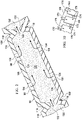
- the open-cavity treatment device 50 includes a plurality of encapsulated leg members 90 that may be coupled to a non-adherent drape 108.
- the non-adherent drape and plurality of encapsulated leg members 90 are supported by the abdominal contents 46.
- One or more of the plurality of encapsulated leg members 90 may be placed in or proximate a first paracolic gutter 92, and one or more of the plurality of encapsulated leg members 90 may be placed in or proximate a second paracolic gutter 94.
- the plurality of encapsulated leg members 90 may be placed at other desired locations, e.g., pelvic cavity, behind the liver, etc.
- Each of the plurality of encapsulated leg members 90 are coupled to the central connection member 96.
- the plurality of encapsulated leg members 90 and the central connection member 96 are in fluid communication.
- Both the plurality of encapsulated leg members 90 and the central connection member 96 are formed with fenestrations 98, 100, 102, 104 that allow fluids in the abdominal cavity 32 to pass.
- the fenestrations 98, 100, 102, 104 may take any shape, such as circular openings, rectangular openings, polygons, etc., but are presented in this illustrative embodiment as slits (elongated openings).
- the open-cavity treatment device 50 includes the non-adherent drape 108 that may be formed of any non-adherent film material that helps prevent tissue from adhering to the non-adherent drape 108.
- the non-adherent drape 108 is formed from a breathable polyurethane film.
- the non-adherent drape 108 is formed with a plurality of fenestrations 110, which may take any shape.
- the open-cavity treatment device 50 includes the central connection member 96 to which the plurality of encapsulated leg members 90 are coupled.
- the central connection member 96 may be encapsulated, including the edges of the central connection member 96, except at leg coupling areas 112 that allow fluid communication with the encapsulated leg members 90.
- the central connection member 96 has apertures or fenestrations, e.g., apertures 104, which allow fluid communication between a connection manifold member 114 and the manifold 64.
- the fluid communication between the connection manifold member 114 and the manifold 64 may be via the deep-tissue closure device 54.
- Each of the encapsulated leg members 90 may be formed with a plurality of defined leg modules, such as leg modules 116.
- a manipulation zone 118 may be located between adjacent leg modules 116. The manipulation zones 118 facilitate movement of the open-cavity treatment device 50 and cutting of the open-cavity treatment device 50 to size the open-cavity treatment device 50.
- Each encapsulated leg member 90 has a leg manifold member 120, which may be a single manifold member that runs between the leg modules 116 or may be formed with discrete components of a manifold material that make up the leg manifold member 120.
- the leg manifold member 120 is disposed within an interior portion 122 of the encapsulated leg member 90.
- the leg manifold member 120 has a first side 124 and second, inward-facing (patient-facing) side 126.
- a first leg encapsulating member 128, which is formed with the fenestrations 98, is disposed on the first side 124 of the leg manifold member 120.
- a second leg encapsulating member 130 which has fenestrations 100, is disposed on the second, inward-facing side 126 of the leg manifold member 120.
- the second leg encapsulating member 130 may be a portion of the non-adherent drape 108.
- fluid may flow between the adjacent leg modules 116.
- fluid is able to enter the fenestrations 98 and 100 and flow into the leg manifold member 120 and then flow toward the central connection member 96 as represented by the flow arrows 132.
- first leg encapsulating member 128 and the second leg encapsulating member 130 may be a single sheet folded over the leg manifold member 120 and sealed.
- the second leg encapsulating member 130 is a portion of the non-adherent drape 108.
- the leg manifold member 120 has peripheral edges 136 that are also covered by a portion of the first leg encapsulating member 128.
- the peripheral edges 136 include a first lateral edge 137 and a second lateral edge 139.
- the first leg encapsulating member 128 covers the first side 124 and the peripheral edges 136 and extends onto a first surface 138 of the non-adherent drape 108 and thereby forms extensions 140.
- the extensions 140 are coupled to the second leg encapsulating member 130 by any attachment device, e.g., welding (e.g., ultrasonic or RF welding), bonding, adhesives, cements, etc., and in this example by welds 142.
- the central connection member 96 is formed with the connection manifold member 114 that is encapsulated with a first connection encapsulation member 146, which has fenestrations 102, and a second connection encapsulation member 152, which has fenestrations 104.
- the first connection encapsulation member 146 is disposed on a first side 148 of the connection manifold member 114.
- a second, inward-facing side 150 of connection manifold member 114 has the second connection encapsulation member 152 disposed proximate to the second, inward-facing side 150.
- the first connection encapsulation member 146 has a peripheral edge 154.
- the second connection encapsulation member 152 has a peripheral edge that corresponds with the peripheral edge 154 of the first connection encapsulation member 146.
- the peripheral edge 154 of the first connection encapsulation member 146 is coupled to the peripheral edge of the second connection encapsulation member 152, except at the leg coupling areas 112 in order to provide flow channels for fluid within the encapsulated leg members 90 to flow into the connection manifold member 114 as suggested by reference arrows 156 in FIGURE 4 . Fluid may also enter directly into the connection manifold member 114 by flowing through the fenestrations 104 as suggested by arrows 158.
- the deep-tissue closure device 54 is deployed proximate to the first connection encapsulation member 146.
- the reduced pressure is communicated through the deep-tissue closure device 54 and that causes fluid to flow from the connection manifold member 114 through the fenestrations 102, through the deep-tissue closure device 54, and into the manifold 64 as is suggested by arrows 160.
- the fluid continues to flow in the direction of the reduced-pressure interface 72 and from there flows to the first reduced-pressure delivery conduit 76.
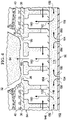
- FIGURES 6-8 another illustrative embodiment of an open-cavity treatment device 202, which might be used with the reduced-pressure, abdominal treatment system 30 of FIG. 1 , is presented.
- the open-cavity treatment device 202 is analogous in most respects to the open-cavity treatment device 50 of FIGURES 1-5 .
- the open-cavity treatment device 202 has a non-adherent drape 204, a plurality of encapsulated leg members 206, and a central connection member 208.
- the non-adherent drape 204 is formed with an oval or arcuate shape, but various shapes are possible.
- the non-adherent drape 204 is formed with a plurality of fenestrations 205 therethrough.
- the non-adherent drape 204 also forms a second leg encapsulating member 228 and a second connection encapsulation member (not shown, but see by analogy 152 in FIGURE 4 ), and the fenestrations 205 in the non-adherent drape 204 serve as flow channels for the encapsulated leg members 206 and the central connection member 208 on the second, inward-facing side.
- Each of the plurality of encapsulated leg members 206 may be formed with a plurality of leg modules 210 with manipulation zones 212 between adjacent leg modules 210.
- the manipulation zones 212 facilitate maneuvering of the plurality of encapsulated leg members 206 within the abdominal cavity and provide an easier location at which to cut the encapsulated leg members 206 when the open-cavity treatment device 202 is being sized.
- visual indicia 214 may be added on the non-adherent drape 204 to help the healthcare provider know where to cut the non-adherent drape 204 for different sizes of application within the abdominal cavity.
- the visual indicia 214 may include cut lines formed with biocompatible ink or welds or fenestrations or other markings that run, at least in part, through the manipulation zones 212.
- the visual indicia 214 may also show size graduations.
- the encapsulated leg members 206 are formed with a leg manifold member 218 having a first side 220 and a second, inward-facing side 222.
- a first leg encapsulating member 224 covers the first side 220 of the leg manifold member 218 and covers lateral edges 226 of the leg manifold member 218.
- the second, inward-facing side 222 of the leg manifold member 218 is covered by a second leg encapsulating member 228, which in this embodiment is a portion of the non-adherent drape 204.
- the first leg encapsulating member 224 is coupled to the second leg encapsulating member 228 by any means known in the art, e.g., welding (e.g., ultrasonic or RF welding), bonding, adhesives, cements, etc.
- welding e.g., ultrasonic or RF welding
- the first leg encapsulating member 224 is coupled to the second leg encapsulating member 228 by a weld 230.
- the weld 230 may be formed on a perimeter portion of each leg module 210 or elsewhere.
- the central connection member 208 is formed analogously to the central connection member 96 in FIG. 4 .
- the first connection encapsulation member 234 and the second connection encapsulation member (not shown but analogous to second connection encapsulation member 152 in FIG. 4 ) are coupled along a peripheral edge 232 using a weld 233 or other coupling means, e.g., welding (e.g., ultrasonic or RF welding), bonding, adhesives, cements, etc..
- welding e.g., ultrasonic or RF welding
- the peripheral edge 232 of the first encapsulation member 234 and the second encapsulation member are not coupled in a way that closes off fluid flow between the encapsulated leg members 206 and the central connection member 208; that is, a flow path for fluids to flow from the encapsulated leg members 206 into the central connection member 208 exists.
- the non-adherent drape 204 that is formed with fenestrations 205 and that may have visual indicia 214 is placed on a substantially flat surface or otherwise presented on a plane.
- the leg manifold members 218 are placed onto the non-adherent drape 204.
- the central connection member 208 is placed on the non-adherent drape 204.
- the central connection member 208 may be formed as an integral member with the leg manifold members 218, and in that case, the central connection member 208 and the leg manifold members 218 would be placed simultaneously.
- the first connection encapsulation member 234 is placed on the central connection member 208, and the first leg encapsulating member 224 is placed on first side, or top (for the orientation shown in FIG. 6 ), of the leg manifold members 218. Then welds 230 and 233 are applied. Thus, the open-cavity treatment device 202 is formed.
- a first non-adherent drape 204 which includes fenestrations 205, may have the leg manifold members 218 and the central connection member 208 placed on the first non-adherent drape 204. Then, a second non-adherent drape, which has fenestrations, is placed over the first non-adherent drape 204, the leg manifold members 218, and the central connection member 208. Then a plurality of welds (e.g., thermal or RF) are made, and the perimeter of the two non-adherent drapes may be welded. In addition, other points on the drape may be welded together.
- welds e.g., thermal or RF
- the two non-adherent drapes may initially not have fenestrations, and fenestrations may be added separately to the non-adherent drapes after assembly so that the fenestrations line up.
- the fenestrations may also be formed with an electrical member that cuts and seals simultaneously to form "button hole" fenestrations through the two non-adherent drapes at the locations where the leg manifold and the central connection member are absent.
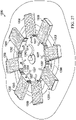
- FIGURE 9 another illustrative embodiment of an open-cavity treatment device 302 is presented.
- the open-cavity treatment device 302 is similar in most respects to that of the open-cavity treatment device 202 shown in FIGURE 6 .
- the open-cavity treatment device 302 has a plurality of encapsulated leg members 306 and a central connection member 312 on a non-adherent drape 348.
- the open-cavity treatment device 302 differs from the open-cavity treatment device 202 primarily in that a fluid delivery subsystem 345 has been added.
- the fluid delivery subsystem 345 allows various fluids, such as medicines or irrigation fluids, to be delivered into the abdominal cavity.
- the various fluids may then be removed by the action of the plurality of encapsulated leg members 306 and the open-cavity treatment device 302 itself.
- the fluid delivery subsystem 345 includes a central port member 347, which may be placed on or in the central connection member 312, for connecting to a delivery conduit (not shown) that delivers the fluid from a site external to the abdominal cavity to the central port member 347.
- Fluidly coupled to the central port member 347 is a plurality of fluid-delivery conduits 349.
- the fluid-delivery conduits 349 may run anywhere on the non-adherent drape 348.
- the fluid-delivery conduits 349 may run along the sides of the encapsulated leg members 306 or on the opposite side of the non-adherent drape 348.
- the fluid-delivery conduits 349 are shown running through the plurality of encapsulated leg members 306.
- the fluid-delivery conduits 349 are open on their distal ends 351 to allow the delivery of fluid there through.
- fluid delivery conduits 349 may have apertures at various locations for delivering fluid and may be closed at the distal ends 351 or open at the distal ends 351.
- the flow of fluid through the distal ends 351 of the fluid-delivery conduits 349 is suggested by arrows 353.
- the open-cavity treatment device 302 may be used in a fashion analogous to that of the open-cavity treatment devices 50 and 202, but at various times, it may be desirable to deliver a fluid through the fluid delivery subsystem 345. For example, it may be desirable to flush the abdominal cavity with an irrigation fluid or to deliver periodic doses of medicine.
- the deep-tissue closure subsystem 56 of the reduced-pressure, abdominal treatment system 30 may be used for closing deep tissues, such as the fascia 36 and, in particular, to approximate the fascia edges 38.
- the deep-tissue closure subsystem 56 which includes the deep-tissue closure device 54, is shown.
- the deep-tissue closure subsystem 56 is particularly well suited for use within the abdominal cavity 32 that involves a deep tissue, such as in the fascia 36.
- the wound in the fascia 36 is shown with fascia edges 38 that typically define the deep-tissue wound. It is desirable to close or apply a closing force on the deep-tissue wound by proximating the fascia edges 38.
- the deep-tissue closure device 54 helps with this purpose.
- the deep-tissue closure device 54 may be placed on top of the open-cavity treatment device 50 and underneath the fascia 36.
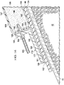
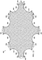
- the deep-tissue closure device 54 includes a contractible matrix 164, which has a first side 166 and a second, inward-facing side 168.
- the contractible matrix 164 is formed with a first plurality of apertures 170 through a contractible matrix material or structure.
- the contractible matrix 164 may also be formed so that a plurality of cells, e.g., open cells 172, is formed on the second, inward-facing side 168.
- the plurality of cells 172 may be formed with cell walls 174, which may include a second plurality of apertures 176.
- the first plurality of apertures 170 may be centered on the cells 172.
- the reduced pressure acts through the first plurality of apertures 170 to provide a gripping force on the fascia 36.
- the gripping force holds, or grips, the fascia 36.
- the reduced pressure may be supplied to the fascia 36 from underneath (for the orientation shown) via fluid communication with the open-cavity treatment device 50, the cells 172, and the first plurality of apertures 170. Reduced pressure may additionally or alternatively be supplied via the manifold 64 and the second plurality of apertures 176.
- the gripping force on the fascia 36 is represented by arrows 178.
- the reduced pressure also urges the contractible matrix 164 inward, i.e., in the direction shown by arrows 29.
- “Inward” in this context means toward a center portion of the reduced-pressure, deep-tissue closure device 54.
- “inward” may be defined as in a direction that would pull the tissue, e.g., the fascia 36, towards the fascia edges 38 of the tissue wound for a deployed reduced-pressure, deep-tissue closure device 54.
- the contractible matrix 164 grips the fascia 36 and goes from a non-contracted position to a contracted position.
- the contractible matrix 164 includes cells that collapse laterally and thereby contract.
- the side walls, which are flexible, of the cells move closer to one another under the influence of reduced pressure. Because the reduced pressure on the first plurality of apertures 170 grips the fascia 36, and the reduced pressure also causes the contractible matrix 164 to contract, a closing force is developed and applied to the fascia 36 that urges the fascia edges 38 into closer approximation. Thus, the fascia 36 experiences a closing force and can be closed or urged into a closed position using reduced pressure.
- the contractible matrix 164 includes a plurality of cells, e.g., cells 172, that collectively define a first volume (V 1 ) when no reduced pressure is applied, e.g., at ambient pressure.
- V 1 first volume
- V 2 second volume
- the second volume is less than the first volume (V 1 ), i.e., V 1 >V 2 , and this change in volume is associated with contraction.
- the deep-tissue closure subsystem 56 is able to provide a closing force on deep tissue, such as fascia 36, and to help provide reduced-pressure treatment within the abdominal cavity 32 and, in particular, to provide reduced-pressure treatment proximate the tissue site 34.
- the reduced pressure may be applied to the tissue site 34 and the abdominal cavity 32 to help promote removal of ascites, exudates or other liquids.
- the reduced pressure may be applied also to stimulate the growth of additional tissue.
- the deep-tissue closure device 54 In using the deep-tissue closure subsystem 56, a number of different embodiments of the deep-tissue closure device 54 may be used. Functionally, it is desirable for the deep-tissue closure device 54 to grip the deep tissue without puncturing the deep tissue and to pull the deep tissue towards the center, e.g., toward the center of a deep-tissue wound 165. When applied to the fascia 36, the deep-tissue closure device 54 approximates the fascia edges 38.
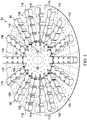
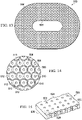
- the contractible matrix 400 for use as part of a reduced-pressure, deep-tissue subsystem is presented.
- the contractible matrix 400 has a first side 402 and a second, inward-facing side 404.
- FIGURE 11 presents the first side 402
- FIGURE 12 presents the second, inward-facing side 404.
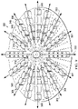
- the contractible matrix 400 is formed with a solid circular shape, but numerous other shapes, such as the elliptical shape shown in FIGURE 13 , an arcuate shape, a rectangular shape, an irregular shape, etc., may be used.
- the first side 402 of the contractible matrix 400 has a first plurality of apertures 406 formed there through and that extend to the second, inward-facing side 404.
- a plurality of cells 408 is formed on the second, inward-facing side 404.
- the cells 408 each have an aperture 406 and an open cell portion.
- Each open cell 408 is formed with cell walls 410.
- Each cell wall 410 may have an intercellular aperture through the cell wall 410 to form a second plurality of apertures analogous to the second plurality of apertures 176 in FIGURE 10 .
- the plurality of cells 408 may be formed as honeycomb cells centered around each of the first plurality of apertures 406. Other shapes for the cells 408 are possible as mentioned further below.
- the contractible matrix 500 has a first side and a second, inward-facing side 504.
- the contractible matrix 500 in this particular illustrative embodiment is formed with an oval shape that has a central opening 506, but as shown in FIGURE 11 could be formed without such an opening.
- the second, inward-facing side 504 of the contractible matrix 500 may be formed with a plurality of cells 508, each centered on a first plurality of apertures 510.
- the plurality of cells 508 may be formed by a plurality of interconnected cell walls 512.
- the cell walls might be formed with a second plurality of apertures formed through the cell wall analogous to the second plurality of apertures 176 in FIG. 10 .
- the contractible matrix 520 may be used in the reduced-pressure, deep-tissue closure subsystem 56 of FIGURE 1 .
- the contractible matrix 520 in this illustrative embodiment is rectangular in shape and has a first plurality of apertures 522 that go from a first side 524 to a second, inward-facing side 526 of the contractible matrix 520.
- a second plurality of apertures 528 may connect the first plurality of apertures 522 or some portion thereof.
- the contractible matrix 520 may have apertures 522 on the first side 524 but no corresponding aperture on the second, inward-facing side 526.
- the contractible matrix 400 has cells that open only to the first side 524 and may have apertures 528, which provide reduced pressure into the cells. When reduced pressure is supplied through apertures 528, the deep tissue is gripped by the apertures 522 and the side walls of the cells are pulled into closer proximity causing the contractible matrix 520 to contract.
- a number of different substances might be used to form the contractible matrices, e.g., the contractible matrix 164 of FIGURE 1 , the contractible matrix 400 of FIGURES 11 and 12 , the contractible matrix 500 of FIGURES 13 and 14 , and the contractible matrix 520 of FIGURE 15 .
- a flexible, contractible material is used for the matrices.
- these contractible matrices 164, 400, 500, and 520 may be formed from flexible, thermal plastic elastomers (TPE); thermoplastic urethane (TPU); silicone rubber; etc.
- Foam is not used for the contractible matrices.
- the material from which the contractible matrics are formed preferably avoid the ingrowth of any tissue.
- the contractible matrix could be formed from a sealed or encapsulated foam member that has apertures for gripping the tissue and a reduced-pressure supply interface.
- the contractible matrix may be formed with a TPU honeycomb material that includes honeycomb cells that are formed with fusion bonding.
- the contractible matrix may be formed from a thermal plastic elastomer (TPE) that allows for expansion and contraction in the xy plane (the plane within the page for FIGURE 13 ) while holding a fairly constant dimension in the z direction (coming out of the page on FIGURE 13 ).
- TPE thermal plastic elastomer
- the contractible matrix may have a stronger material (or more material) concentrated in the z direction than in the xy directions.
- voids may be added to prescribe the pattern of collapse.
- the contractible matrix may be formed using a thermoplastic urethane (TPU) material that may have an additional film on the contractible matrix on the first side, e.g., on first side 402 of the contractible matrix 400 of FIGURE 11 .
- TPU thermoplastic urethane
- the surface-wound closure subsystem 60 is now presented. It is desirable to help provide a closing force to the surface wound 180 on the epidermis 44 and, in particular, between the surface-wound edges 182. As shown in FIGURES 1 and 16 , the surface-wound closure subsystem 60 may be used for this purpose.
- the surface-wound closure subsystem 60 develops a closing force represented by arrows 184 that is communicated to the epidermis 44 and urges the surface-wound edges 182 towards each other.
- the surface-wound closure subsystem 60 includes a first attachment member 186 that has a first base member 177 and a first wall 188, or wall member, ( FIGURE 16 ).
- the sealed contracting member 196 may be secured to the wall 188 by a securing device, e.g., adhesive 189.
- the first base member 177 has a first side 190 and a second, inward-facing side 191.
- the first base member 177 and the first wall 188 may be made from numerous materials, but a material is preferred that provides some flexibility.
- the first attachment member 186 may be formed with the first base member 177 and the first wall 188 made from polypropylene, or a rigid silicone, etc.
- a first adhesive 192 may be applied to the second, inward-facing side 191 of the first base member 177 to allow the first base member 177 to be releasably attached directly to a portion of a patient's epidermis 44 or indirectly if a polyurethane film or other sealing member 66 is placed on the epidermis 44 first.
- staples, or sutures, or other invasive approaches might be used to attach the first base member 177.
- the first attachment member 186 may be applied directly on top of the epidermis 44, or on top of the sealing member 66, so that whatever forces are applied on the first attachment member 186 are transmitted directly, or indirectly, to the epidermis 44. References to applying the first attachment member 186 to the epidermis 44 should be deemed to include application on top of the sealing member 66 as well.
- the second attachment member 193 is analogous to the first attachment member 186. While the surface-wound closure subsystem 60 of FIGURE 1 only shows two attachment members 186, 193, other attachment members may be dispersed around the surface wound 180 in a spaced fashion and typically in pairs. Having at least two attachment members, e.g., attachment members 186 and 193, allows the closing force to be developed.
- One or more of the attachment members e.g., attachment member 186, has a reduced-pressure interface 194 for receiving reduced pressure from a second reduced-pressure delivery conduit 195.
- the first attachment member 186 may include the reduced-pressure interface 194 to which the second reduced-pressure delivery conduit 195 is fluidly coupled.
- the surface-wound closure subsystem 60 includes a sealed contracting member 196.
- the sealed contracting member 196 may be formed from the same type of materials as the manifold 64, but it may be desirable to include a material that has fewer apertures or holes through the material.
- the sealed contracting member 196 may be formed from a contracting manifold material that is enveloped by a first sealing member 181 and a second sealing member 183. In addition, it may be desirable in some situations to have a material that will contract less in the vertical (for the orientation shown in FIG. 1 ) and more in the horizontal plane (for the orientation shown FIG. 1 ).
- the sealed contracting member 196 has a first side 197 and a second, inward-facing side 198.
- the sealed contracting member 196 also has a peripheral edge 199.
- the sealed contracting member 196 may be sealed by having the first sealing member 181 ( FIG. 16 ) applied to the first side 197, and the second sealing member 183 applied to the second, inward-facing side 198.
- the peripheral edge 199 may be sealed by a peripheral sealing member 185 having a surface 200 disposed against the peripheral edge 199.
- the wall 188 may also be used to the seal peripheral edge 199.
- the second, inward-facing side 198 may be sealed by placement against the sealing member 66 or the patient's epidermis 44.
- the sealed contracting member 196 might also be sealed by being coated with a gas-impervious material.
- the sealed contracting member 196 may be sealed using polyurethane film or silicone as the sealing members 181, 183 and then ultrasonically welding or RF welding the ends of the sealing members 181, 183 to cover the peripheral edge 199. When reduced pressure is supplied to the sealed contracting member 196, the sealed contracting member 196 contracts to develop the closing force, which is represented by the arrows 184.
- the sealed contracting member 196 may be formed with an opening 187 ( FIG. 1 ) on a portion of the sealed contracting member 196 for receiving an extension portion 179 of the reduced-pressure interface 72.
- the extension portion 179 extends through the sealed contracting member 196 and into the manifold 64.
- the reduced-pressure supply subsystem 62 may have a second reduced-pressure source 84 that delivers reduced pressure to the second reduced-pressure delivery conduit 195, which delivers the reduced pressure to the second reduced-pressure interface 194.
- the second reduced-pressure source 84 could be used to provide reduced pressure to the first reduced-pressure delivery conduit 76 (in addition to or in lieu of first reduced-pressure source 77) as well as to the second reduced-pressure delivery conduit 195.
- the first reduced-pressure source 77 could supply reduced pressure through conduit 86 to the second reduced-pressure conduit in addition to or in lieu of the second reduced-pressure source 84.
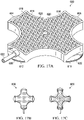
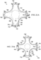
- a surface-wound closure device 600 for providing a closing force on a surface wound, e.g., surface wound 180 in FIG. 1 .
- the surface-wound closure device 600 may be used as the surface-wound closure subsystem 60 of FIGURE 1 .
- the surface-wound closure device 600 has a plurality of attachment members: a first attachment member 602, a second attachment member 604, a third attachment member 606, and a fourth attachment member 608.
- Each attachment member 602, 604, 606, 608 has an attachment device for releasably attaching the member to the patient's epidermis (or to a sealing member).
- the first attachment member 602 includes an attachment device that is an adhesive 610 for attachment to the patient's epidermis and similarly, third attachment member 606 has an adhesive 612.
- the second and fourth attachment members also have an attachment device, such as an adhesive, for securing the members to a patient's epidermis. While non-invasive means are generally considered preferable, it may also be that the attachment members 602, 604, 606, 608 may be secured using sutures, staples, or other invasive mechanical devices.
- a wall 614 which is coupled to the plurality of attachment members, forms a circumferential wall having an interior space into which a contracting member 616, or contracting material, is placed.
- the contracting member 616 is attached to the circumferential wall 614 at least at points proximate to each attachment member 602, 604, 606, 608.
- the circumferential wall 614 may be made of polypropylene, rigid silicone, or other semi-rigid material that allows the circumferential wall 614 to flex when in a closing mode, i.e., when reduced pressure is applied.
- the contracting member 616 may be made of the same kind of materials as sealed contracting member 196 in FIGURE 1 .
- the contracting member 616 in operation should be sealed and may be sealed by films, layers, or drapes being applied to a first side 618, or top side (for the orientation shown).
- the contracting member 616 may also be sealed with the circumferential wall 614 covering the peripheral edge, the sealing member may provide a seal on the bottom, and then a film or drape placed over the top.
- the contracting member 616 may simply be enveloped in a polyurethane film that has been welded to form an envelope around the material.
- An opening 620 may be formed through the contracting member 616.
- the opening 620 is for placement of part of a reduced-pressure interface, or port, extending to a manifold below the surface-wound closure device 600.
- a reduced-pressure conduit 622 delivers reduced pressure into the contracting member 616; this may be accomplished by directly applying the reduced-pressure conduit 622 into any portion of the contracting member 616, but is shown using a reduced-pressure interface 624 formed on a portion of the circumferential wall 614.
- the attachment members e.g., first attachment member 602 and second attachment member 604, are placed opposite each other and on each side of a surface wound and releasably attached.
- the first attachment member 602 and the fourth attachment member 608 may be releasably secured to one side of a surface wound at different spaced portions and the attachment members 604 and 606 may be placed on the other side of the surface wound.
- the surface-wound closure device 600 is installed, the surface-wound closure device 600 is in a non-contracted position.
- FIGURE 17B shows the surface-wound closure device 600 in a top view and in a non-contracted position
- FIGURE 17C shows the surface-wound closure device 600 in the contracted position.
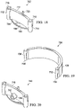
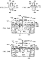
- a modular, reduced-pressure wound-closure system 700 which is suitable as another illustrative embodiment of a surface-wound closure subsystem 60, is presented.
- the modular, reduced-pressure wound-closure system 700 uses a number of modular components that may be movably coupled to accommodate various sizes and shapes of wounds and to provide a closing force directed toward a central portion of the surface wound.
- a plurality of attachment-base members such as attachment-base member 702 may be used.
- the attachment-base member 702 has a base 704, which has a first side 706 and a second, inward-facing side 708.
- the second, inward-facing side 708 of the base 704 may have an adhesive (not shown but analogous to 610 in FIG. 17A ) for attaching the attachment-base member 702 to a patient's epidermis (or to a sealing member).
- the adhesive on the second, inward-facing side 708 may be initially covered with a releasable backing material that may be removed before application on the patient.
- the attachment-base member 702 also includes a wall 710 that is coupled to the base 704 or formed integrally with the base 704.
- the wall 710 has a first end 712 and a second end 714.
- the first end 712 may be formed with a first movable connection member 716 that is formed as an integral part or attached to the first end 712.
- the second end 714 may be formed with a second movable connection member 718.
- the wall 710 or base 704 may have a hook member 720 attached to the wall 710 or base 704.
- the hook member 720 may be used to help grip and hold a sealed contracting member 722 (see FIGURE 21A ).
- Each connecting member 726 may be used as part of the modular, reduced-pressure wound-closure system 700.
- Each connecting member 726 has a second wall 728 with a first end 730 and a second end 732.
- the second wall 728 may be shaped to have an arcuate configuration as shown or may be straight.
- the first end 730 may be formed with, or have coupled to the first end 730, a third movable connection member 734.
- the second end 732 may have a fourth movable connection member 736.
- the movable connection members 734 and 736 are sized and configured to cooperate with movable connection members, e.g., movable connection members 716 and 718, in a coordinated fashion that allows relative movement, such as pivotable movement, between each attachment-base member 702 and each adjacent, coupled connecting member 726.
- the movable connection members 734 and 736 are shown as being pin-shaped members.
- the first and second movable connection members 716 and 718 are sockets that are sized and configured to receive the pin shapes of movable connection members 734 and 736.
- a reduced-pressure conduit such as conduit 622 in FIGURE 17A
- a reduced-pressure interface might be used on the wall 710 of the attachment-base member 702.
- the attachment-base member 702 might be modified to form a reduced-pressure interface member 740 as shown in FIGURE 20 .
- the reduced-pressure interface member 740 is analogous to that of the attachment-base member 702 except that a reduced-pressure interface 742 has been included.
- the reduced-pressure interface 742 may be a port 744 that extends through a wall 746.
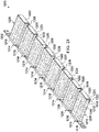
- FIGURES 21A and 21B The previously presented modular components, attachment-base member 702, connecting member 726, and reduced-pressure interface member 740, may be combined to form various shapes; one example is shown in FIGURES 21A and 21B with the modular, reduced-pressure wound-closure system 700 shown around and over a surface wound 701.
- the modular, reduced-pressure wound-closure system 700 is shown with a plurality of attachment-base members.
- the modular, reduced-pressure wound-closure system 700 includes the first attachment-base member 702, a second attachment-base member 750, and a third attachment-base member 752.
- a fourth attachment-base member is shown, but has been modified to form the reduced-pressure interface member 740, which has the reduced-pressure interface 742.
- a reduced-pressure conduit 754 may be coupled to the reduced-pressure interface 742.
- a plurality of movable connecting members is used to connect each of the plurality of attachment-base members 702, 750, 752, 740 (interface).
- the attachment-base member 702 is movably coupled at the first end 712 to the first connecting member 726 at the second end 732 of the first connecting member 726.
- the second attachment-base member 750 is movably coupled to the second connecting member 756.
- the second connecting member 756 is also movably coupled to the third attachment-base member 752.
- the third attachment-base member 752 is movably coupled to a third connecting member 758, which is also movably coupled to the reduced-pressure interface member 740.
- the reduced-pressure interface member 740 is also movably coupled to a fourth connecting member 760.
- the plurality of attachment-base members and plurality of connecting members form a circumferential wall 780 defining an interior space 781 into which sealed contracting member 722 is disposed.
- alternating members of the plurality of attachment-base members and plurality of connecting members provide for connections that move and are thus movably coupled. Movably coupling the members is helpful when the modular, reduced-pressure wound-closure system 700 goes from the non-contracted position of FIGURE 21A to the contracted position shown in FIGURE 21B . It will also be appreciated that while only four connecting members and four attachment-base members are shown in this illustration, any number of these components might be used for bigger or smaller applications. For example, a modular, reduced-pressure closure system 800 in FIGURE 22 shows a much larger system configuration.
- the modular, reduced-pressure closure system 800 in this illustrative embodiment includes a plurality of attachment-base members having seven attachment-base members 802 and another that has been modified to form a reduced-pressure interface 804.
- the modular, reduced-pressure closure system 800 also includes a plurality of connecting members, which in this illustrative embodiment includes eight connecting members 806.
- the plurality of attachment-base members 802 and the plurality of connecting members 806 are movably coupled to form a circumferential wall 808 that defines an interior space 810.
- a sealed contracting member 812 is placed within the interior space 810 and is coupled to at least the plurality of attachment-base members 802.
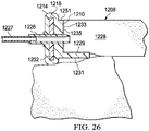
- the reduced-pressure connector 900 is operable to fluidly connect two different compartments or areas.
- the reduced-pressure connector 900 has a first end 902 and a second end 904.
- An entry portion 906 is formed on the second end 904.
- the entry portion 906 may be shaped as an inverted conical section to facilitate insertion through various materials, such as sealing members and manifolds.
- a plurality of flutes 908 may be located to facilitate fluid flow.
- a flange portion 910 may be formed between the first end 902 and the second end 904.
- the flange portion 910 has a first surface 912 and a second surface 914.
- the first end 902 may also be shaped and configured for easy entry through a sealing member or other material.
- Two different, illustrative applications of the reduced-pressure connector 900 are shown in FIGURES 24A and 24B .
- FIGURE 24A a portion of a reduced-pressure, wound-closure and treatment system 1000 is presented.
- the reduced-pressure, wound-closure and treatment system 1000 is analogous in many respects to the surface-wound closure subsystem 60 of FIGURE 1 .
- a manifold 1018 is placed within a body cavity, e.g., an abdominal cavity 1010, to help provide reduced-pressure treatment therein.
- the manifold 1018 is shown proximate to subdermal tissue 1014 and a surface wound 1011.
- a sealing member 1032 is placed on the patient's epidermis 1008 over the abdominal cavity 1010 and the surface wound 1011.
- the surface wound has wound edges 1012.
- the sealing member 1032 has an adhesive 1034 that helps to form a pneumatic seal with the epidermis 1008.
- the sealing member 1032 as applied forms a pneumatic seal over the abdominal cavity 1010.
- a portion 1071 of a wound-closure device or subsystem is also presented.
- the portion 1071 includes a portion of a sealed contracting member 1088.
- the sealed contracting member 1088 is sealed, at least in part, by a first sealing member 1096 and a second sealing member 1098.
- the sealed contracting member 1088 is attached, at least at certain portions, to the patient's epidermis 1008.
- reduced pressure is supplied to an interior of the sealed contracting member 1088, the sealed contracting member 1088 contracts and thereby pulls towards a central portion and develops a closing force that is transmitted to the surface wound 1011.
- reduced pressure is supplied by a reduced-pressure source to a reduced-pressure conduit 1042.
- the reduced-pressure conduit 1042 is fluidly coupled to a reduced-pressure interface 1038, which has an extension portion 1102.
- the extension portion 1102 extends through the sealing member 1032 and into the manifold 1018.
- reduced pressure is delivered to the manifold 1018 and pulls fluids towards the extension portion 1102 as suggested by arrows 1044.
- the reduced-pressure connector 900 has been added.
- the reduced-pressure connector 900 is deployed with the first end 902 within the interior of the sealed contracting member 1088 and the second end 904 within the manifold 1018.
- the reduced-pressure connector 900 thereby fluidly couples the interior of the sealed contracting member 1088 with the manifold 1018. Reduced pressure is thereby delivered from the reduced-pressure interface 1038, to the manifold 1018, and to the interior of the sealed contracting member 1088. The reduced pressure delivered through the reduced-pressure connector 900 pulls fluids within the sealed contracting member 1088 as suggested by arrows 1045.
- the first surface 912 of the reduced-pressure connector 900 abuts the sealing member 1032 and the second surface 914 abuts the manifold 1018.
- the reduced-pressure connector 900 may be deployed in numerous ways. For example, with reference to FIGURE 17A , the reduced-pressure connector 900 can be placed over a cell, e.g., cell 625, of the contracting member 616, and pushed through the sealing member thereon.
- the entry portion 906 is shaped to facilitate such an entry.
- the sealing member thereon should self-seal after insertion, but an additional portion of sealing material could also be added over the insertion point.
- the reduced-pressure connector 900 is pushed into the sealed contracting member 616 until the second surface 914 abuts the second (bottom for orientation shown) sealing member 1098 and the entry portion 906 extends out of the contracting member 616.
- the entry portion 906 can then be inserted through the sealing member 1032 and into the manifold 1018.
- numerous approaches may be taken for deploying the reduced-pressure connector 900 and the reduced-pressure connector 900 may take many different configurations, but the deployed reduced-pressure connector 900 functionally provides a fluid coupling of the sealed contracting member 1088 and the manifold 1018.
- the extension portion 1102 of the reduced-pressure interface 1038 terminates within the sealed contracting member 1088 and delivers reduced pressure within the sealed contracting member 1088.
- the reduced-pressure connector 900 is deployed in the same manner as previously presented, but now delivers reduced pressure to the manifold 1018. In other words, fluids are drawn through the manifold 1018, through the reduced-pressure connector 900, through an interior of the sealed contracting member 1088 to the extension portion 1102 of the reduced-pressure interface 1038 and then through the reduced-pressure conduit 1042.
- the modular, reduced-pressure closure system 1200 includes a spacing member, e.g., a flexible strap 1202, which is shown in a linear position in FIGURE 25 and shaped into a closed loop 1204 in FIGURE 27 .
- the flexible strap 1202 may be shaped into the closed loop 1204 around a surface wound 1206, such as an opening on a patient's abdomen.
- a plurality of modular closing members 1208 is selectively coupled to the flexible strap 1202.
- the number of modular closing members 1208 included in the plurality of modular closing members on the flexible strap 1202 is determined by the size of the closed loop 1204 needed to surround the surface wound 1206. Thus, to cover the surface wound 1206 in FIGURE 27 , eight modular closing members 1208 have been included on the flexible strap 1202. While a flexible strap 1202 has been referenced, any spacing member that holds the modular closing members 1208 in a spaced relationship around the surface wound 1206 may be used.
- the spacing member may be one or more tie wires that hold the modular closing members 1208 in a spaced relationship or a flexible adhesive film placed on top of the modular closing members 1208 that hold the modular closing members 1208 in a spaced relationship.
- each of the modular closing members 1208 has a first end 1210 and a second end 1212.
- a connection member 1214 is coupled to the first end 1210 of each modular closing member 1208.
- each connection member 1214 includes an attachment loop 1216 through which the flexible strap 1202 may be placed.
- the attachment loops 1216 allow each modular closing member 1208 to be positioned in a desired location along the flexible strap 1202.
- a portion of each attachment loop 1216 may interface with one of a plurality of strap openings 1218 to help hold the connection member 1214 in a desired position on the flexible strap 1202.
- the second reduced-pressure interface 1226 is shown coupled to the connection member 1214.
- a reduced-pressure conduit 1227 is fluidly coupled to the second reduced-pressure interface 1226 in order to provide reduced pressure to the second reduced-pressure interface 1226.
- the second reduced-pressure interface 1226 delivers the reduced pressure to a sealed contracting member 1228 and may function as a pin to hold the connection member 1214 in place relative to the flexible strap 1202.
- the second reduced-pressure interface 1226 may extend through an opening in connection member 1214, through the attachment loop 1216, through the flexible strap 1202 and into the sealed contracting member 1228.
- the sealed contracting member 1228 may be held to a base 1231 by an adhesive layer 1229.
- a peripheral edge 1233 of the sealed contracting member 1228 may be held to a wall 1251 of connection member 1214 by an adhesive layer 1235.
- reduced pressure can be supplied to the modular closing member 1208 and more particularly to the sealed contracting member 1228.
- FIGURES 28 and 29 show alternative ways of providing reduced pressure to the sealed contracting member 1228 as will be described further below.
- the sealed contracting member 1228 is made of the same or similar materials as contracting member 196 ( FIG. 1 ), 616 ( FIG. 17A ), and 722 ( FIG. 21A ).
- the sealed contracting member 1228 is sealed to form a pneumatic seal about the sealed contracting member 1228.
- An adhesive layer 1229 may be used to hold the sealed contracting member 1228 to the base 1231.
- An adhesive layer 1235 may be also be used to attach the peripheral edge 1233 of the sealed contracting member 1228 to the wall 1251.
- attachment members 1220 may be coupled to each of the second ends 1212 of the modular closing members 1208.
- each of the attachment members 1220 may be formed with a base 1222 and a wall 1224.
- An adhesive layer may be used to hold the sealed contracting member 1228 to the base 1222.
- An adhesive layer may also be used to hold the sealed contracting member to the wall 1224.
- An adhesive may be used to hold the inward-facing side 1236 of the base 1222 against the patient's epidermis.
- Reduced pressure may be provided to a sealed contracting member 1308 through the connection member.
- the modular closing member may have a connection member 1316 that selectively attaches to a flexible strap 1302.
- An adhesive 1330 may be used to hold the sealed contracting member 1308 to the connection member 1316.
- the connection member 1316 may have a wall 1324 and a base 1322.
- a reduced-pressure interface 1327 may be formed on the base 1322 and configured to enter the sealed contracting member 1308.
- the reduced-pressure interface 1327 is sized and configured to engage a manifold 1380, which is in fluid communication, or is fluidly coupled, to a reduced-pressure source. The reduced pressure is delivered to the manifold 1380.
- an attachment member 1420 which has a base portion 1422 and a wall 1424, is shown with an alternative reduced-pressure interface 1426.
- the reduced-pressure interface 1426 is formed through the wall 1424.
- a reduced-pressure conduit 1427 delivers reduced pressure from a reduced-pressure source to the reduced-pressure interface 1426.
- the reduced-pressure interface 1426 delivers reduced pressure to a sealed contracting member 1428.
- the sealed contracting member 1428 may be held to the base 1422 by an attachment device, e.g., adhesive 1430.
- the base 1422 may be held by an attachment device 1432, e.g., adhesive 1436, to the patient's epidermis.
- the sealed contracting member 1428 may also be held by an attachment device 1432, e.g., adhesive 1434, to the wall 1424.
- the modular, reduced-pressure closure system 1200 is used by the healthcare provider who first assesses the size of the surface wound 1206 and determines the number of modular closing members 1208 that are appropriate for the size of the wound.
- a lookup table might be provided to suggest the number based on the linear measurement of the circumference of the surface wound 1206.
- An appropriate number, which make up the desired plurality of modular closing members 1208, are then selectively coupled to the flexible strap 1202.
- the flexible strap 1202 is shaped into the closed loop 1204 around the surface wound 1206 and is preferably disposed inboard of the peripheral edges of the surface wound 1206.
- the closed loop 1204 is secured as a loop using any number of means, such as a ratchet, snap, a fastener on the flexible strap 1202, ratchet ties, flexible peg and slot members, etc.
- each of the plurality of attachment members 1220 are attached to the patient's epidermis proximate the edge of the surface wound 1206.
- the statement that each of the plurality of attachment members 1220 are attached to the epidermis may include that the attachment member 1220 is attached on top of a sealing member being used for reduced-pressure treatment.
- a closing force is developed as represented by arrows 1240.
- the closed loop 1204 provides an open area in the middle of the loop which readily accommodates a reduced-pressure interface 1242 that may be used to supply reduced pressure to a portion of a reduced-pressure treatment system (see, e.g., subsystem 58 in FIG. 1 ).
- the healthcare provider may first put in an open-cavity treatment device 50 as part of an open-cavity treatment subsystem 52.
- the open-cavity treatment device 50 may be sized initially to fit the particular application.
- the open-cavity treatment device 202 may be cut along visual indicia 214 through the manipulation zones 212 to properly size the dressing.
- the open-cavity treatment device 50 is placed within the abdominal cavity 32 and on top of the abdominal contents 46.
- the encapsulated leg members 90 of the open-cavity treatment device 50 may be tucked and worked into desired locations, e.g., the paracolic gutters 92, 94, pelvic cavity, behind a patient's liver, etc.
- the healthcare provider may place the deep-tissue closure device 54 on the first side (or top for the orientation shown) of the open-cavity treatment device 50.
- the deep-tissue closure device 54 which is part of a deep-tissue closure subsystem 56, may need to be sized by cutting the deep-tissue closure device 54 to a desired size to accommodate the deep-tissue wound.
- the healthcare provider may help to position layers of tissue, namely fascia 36, on the first side (or top for the orientation shown) of the deep-tissue closure device 54.
- the manifold 64 may be inserted within the abdominal cavity 32 and on top of a portion of the deep-tissue closure device 54.
- the sealing member 66 may then be placed over the opening of the abdominal cavity 32 and on the epidermis 44 to provide a pneumatic seal. This may be done by removing releasable backing from the adhesive 70 and then placing the adhesive 70 against the epidermis 44. Then, to help provide additional closing force and support, the surface-wound closure subsystem 60 may be applied. Any of numerous possible embodiments of a surface-wound closure subsystem may be used. In addition, various other subsystems and alternatives might be used as part of the reduced-pressure, abdominal treatment system 30.
- the first attachment member 186 may be applied on one side of the surface-wound edges 182 and a second attachment member 193 may be applied generally at a position opposite the first attachment member 186 and on the other side of surface-wound edge 182.
- the attachment members 186 and 193 may be attached by removing releasable backing from an adhesive layer, e.g., first adhesive 192 on the first attachment member 186, and applying the adhesive against the sealing member 66.
- a portion of the reduced-pressure interface 72 may then be placed into opening 187 of the surface surface-wound closure subsystem 60 and into the manifold 64.
- the first reduced-pressure delivery conduit 76 may be fluidly coupled to the reduced-pressure interface 72 and to the reduced-pressure supply subsystem 62, which delivers reduced pressure to the first reduced-pressure delivery conduit 76.
- the surface surface-wound closure subsystem 60 includes at least one second reduced-pressure interface 194, which is fluidly coupled to a second reduced-pressure delivery conduit 195.
- the second reduced-pressure delivery conduit 195 is fluidly coupled to the reduced-pressure supply subsystem 62, which delivers a reduced pressure into the second reduced-pressure delivery conduit 195.
- the healthcare provider may then activate the reduced-pressure supply subsystem 62, which delivers reduced pressure (a first reduced pressure or treatment-reduced-pressure) to the reduced-pressure treatment subsystem 58 and in particular to the manifold 64.
- reduced pressure is also communicated to the open-cavity treatment device 50 and the deep-tissue closure device 54.
- reduced pressure might also be supplied to the surface-wound closure subsystem 60 by the manifold 64, but in the illustrative embodiment of FIGURE 1 , reduced pressure (a second reduced pressure or closing-reduced-pressure) is supplied by the second reduced-pressure delivery conduit 195 to the sealed contracting member 196 causing the sealed contracting member 196 to contract and pull the surface-wound edges 182 of the epidermis 44 together.
- reduced pressure a second reduced pressure or closing-reduced-pressure
- the reduced-pressure, abdominal treatment system 30, and particularly the open-cavity treatment device 50 helps remove ascites and other fluids from the abdominal cavity 32 and the tissue site 34 without adhering to the abdominal contents 46.
- the reduced-pressure, abdominal treatment system 30 utilizes the deep-tissue closure subsystem 56 to help close the fascia 36 without the fascia "rolling" or causing other problems and without requiring puncture wounds to the fascia 36.
- the reduced-pressure, abdominal treatment system 30 helps generally to provide reduced-pressure treatment within the abdominal cavity 32 by way of the reduced-pressure treatment subsystem 58, which includes the manifold 64.
- the reduced-pressure, abdominal treatment system 30 also helps close the surface wound 180 in the epidermis 44 by using the surface surface-wound closure subsystem 60.
Claims (13)
- Système de traitement abdominal (30), comprenant :un sous-système de fermeture de plaie superficielle (60) pour la fourniture d'une force de fermeture (184) à une plaie superficielle (180), etun sous-système d'approvisionnement en pression réduite (62) employable pour développer une pression réduite pour une utilisation dans le sous-système de fermeture de plaie superficielle,caractérisé par le sous-système de fermeture de plaie superficielle (60) comprenant :une pluralité d'éléments de fixation (186, 193) pour la fixation de manière amovible à des parties respectives d'épiderme d'un patient (44) à proximité des bords de la plaie superficielle, dans lequel la pluralité d'éléments de fixation sont espacés les uns des autres, etun élément de contraction étanche (196) couplé à chacun de la pluralité d'éléments de fixation (186, 193) et employable pour se contracter lorsqu'il est placé sous une pression réduite,dans lequel l'élément de contraction étanche (196) comprend :un matériau collecteur de contraction (196) ayant un premier côté (197) et un deuxième côté, faisant face vers l'intérieur (198), et un bord périphérique (199) ;un premier élément d'étanchéité (181) disposé contre le premier côté (197) du matériau collecteur de contraction (196) ;un deuxième élément d'étanchéité (183) disposé contre le deuxième côté, faisant face vers l'intérieur (198) du matériau collecteur de contraction (196) ;un dispositif d'étanchéité périphérique disposé contre le bord périphérique (199) du matériau collecteur de contraction (196) ; etdans lequel le premier élément d'étanchéité (181), le deuxième élément d'étanchéité (183), et le dispositif d'étanchéité périphérique sont employables pour étanchéifier pneumatiquement le matériau collecteur de contraction (196) ;dans lequel une force de fermeture est développée entre la pluralité d'éléments de fixation lorsqu'une pression réduite est approvisionnée par un sous-système d'approvisionnement en pression réduite à l'élément de contraction étanche.
- Système de traitement abdominal (30) selon la revendication 1, dans lequel un premier élément de fixation (186) de la pluralité d'éléments de fixation comprend :un premier élément de base (177) ayant un premier côté (190) et un deuxième côté, faisant face vers l'intérieur (191) ;une première paroi externe (188) couplée au premier élément de base (177) ; etun premier adhésif (192) couplé au deuxième côté, faisant face vers l'intérieur (191).
- Système de traitement abdominal (30) selon la revendication 1, dans lequel :un premier élément de fixation (186) de la pluralité d'éléments de fixation comprend un premier élément de base (177) et un premier adhésif (192) ; etun deuxième élément de fixation (193) de la pluralité d'éléments de fixation comprend un deuxième élément de base et un deuxième adhésif.
- Système de traitement abdominal (30) selon la revendication 1, dans lequel un ou plusieurs de la pluralité d'éléments de fixation (186, 193) comprend une interface de pression réduite (194) pour la réception d'une pression réduite à partir d'un conduit de distribution de pression réduite (195).
- Système de traitement abdominal (30) selon la revendication 3, comprenant en outre un troisième élément de fixation (606) de la pluralité d'éléments de fixation pour la fixation de manière amovible à une troisième partie de l'épiderme (44) et couplé à l'élément de contraction étanche (196).
- Système de traitement abdominal (30) selon la revendication 5, comprenant en outre un quatrième élément de fixation (608) de la pluralité d'éléments de fixation pour la fixation de manière amovible à une quatrième partie de l'épiderme (44) et couplé à l'élément de contraction étanche (196).
- Système de traitement abdominal (30) selon la revendication 1, dans lequel :la pluralité d'éléments de fixation (186, 193) comprend une pluralité d'éléments de base de fixation (702), chaque élément de base de fixation (702) ayant une base (704) et une première paroi (710) ayant une première extrémité (712) et une deuxième extrémité (714), la première extrémité (712) de la première paroi (710) ayant un premier élément de connexion mobile (716) et la deuxième extrémité (714) de la première paroi (710) ayant un deuxième élément de connexion mobile (718) ;l'appareil (60) comprend en outre une pluralité d'éléments de connexion (726), chaque élément de connexion (726) ayant une deuxième paroi (728) avec une première extrémité (730) et une deuxième extrémité (732), la première extrémité (730) de la deuxième paroi (728) ayant un troisième élément de connexion mobile (734) et la deuxième extrémité (732) de la deuxième paroi (728) ayant un quatrième élément de connexion mobile (736), chaque élément de connexion (726) pour le couplage de manière mobile à l'un de la pluralité d'éléments de base de fixation (702) ; etcomprenant en outre une interface de pression réduite (742) couplée à l'élément de contraction étanche (196) ;dans lequel la pluralité d'éléments de base de fixation (702) et la pluralité d'éléments de connexion (726) sont employables pour se coupler de manière mobile pour former une paroi circonférentielle (780) définissant un espace interne (781) et dans lequel l'élément de contraction étanche (196) est à disposer au sein de l'espace interne (781).
- Système de traitement abdominal (30) selon la revendication 7, dans lequel la pluralité d'éléments de base de fixation (702) et la pluralité d'éléments de connexion (726) sont couplés à l'élément de contraction étanche (196).
- Système de traitement abdominal (30) selon la revendication 7, dans lequel l'interface de pression réduite (814) est couplée de manière fluidique à l'élément de contraction étanche (196) à titre d'au moins un élément d'interface de pression réduite (740) couplé à au moins un élément de base de fixation (702).
- Système de traitement abdominal (30) selon la revendication 1, dans lequel le dispositif d'étanchéité périphérique comprend une couche d'étanchéité.
- Système de traitement abdominal (30) selon la revendication 1, dans lequel le dispositif d'étanchéité périphérique comprend une paroi externe.
- Système de traitement abdominal (30) selon la revendication 1, comprenant en outre :un dispositif de traitement de cavité ouverte (50) pour la fourniture d'une pression réduite à proximité de contenus abdominaux (46) ; etun dispositif de fermeture de tissu profond (54) à appliquer à proximité du dispositif de traitement de cavité ouverte (50) pour l'application d'une force de fermeture sur une plaie de tissu profond sur un fascia (36), le dispositif de fermeture de tissu profond (54) ayant une matrice contractible (164).
- Système de traitement abdominal (30) selon la revendication 1, comprenant : une pluralité des sous-systèmes de fermeture de plaie superficielle (60) ;une sangle flexible (1202) employable pour être formée en une boucle fermée (1204) ;une pluralité d'éléments de fermeture modulaires (1208), dans lequel chacun de la pluralité d'éléments de fermeture modulaires (1208) comprend un sous-système de fermeture de plaie superficielle respectif ; etun élément de connexion (1214) couplé à la première extrémité (1210) de l'élément de contraction étanche (1428), dans lequel l'élément de connexion (1214) est employable pour se coupler de manière sélective à la sangle flexible (1202) ; etune interface de pression réduite (1038) couplée de manière fluidique à l'élément de contraction étanche (1428).
Applications Claiming Priority (6)
| Application Number | Priority Date | Filing Date | Title |
|---|---|---|---|
| US10948608P | 2008-10-29 | 2008-10-29 | |
| US10939008P | 2008-10-29 | 2008-10-29 | |
| US10941008P | 2008-10-29 | 2008-10-29 | |
| US10944808P | 2008-10-29 | 2008-10-29 | |
| EP09789697.1A EP2340064B1 (fr) | 2008-10-29 | 2009-05-15 | Systèmes et procédés de traitement abdominal sous pression réduite |
| PCT/US2009/044268 WO2010051073A1 (fr) | 2008-10-29 | 2009-05-15 | Systèmes et procédés de traitement abdominal sous pression réduite |
Related Parent Applications (1)
| Application Number | Title | Priority Date | Filing Date |
|---|---|---|---|
| EP09789697.1A Division EP2340064B1 (fr) | 2008-10-29 | 2009-05-15 | Systèmes et procédés de traitement abdominal sous pression réduite |
Publications (2)
| Publication Number | Publication Date |
|---|---|
| EP3225261A1 EP3225261A1 (fr) | 2017-10-04 |
| EP3225261B1 true EP3225261B1 (fr) | 2022-12-07 |
Family
ID=40852212
Family Applications (14)
| Application Number | Title | Priority Date | Filing Date |
|---|---|---|---|
| EP15154703.1A Active EP2896414B8 (fr) | 2008-10-29 | 2009-05-15 | Dispositifs et systèmes de traitement de plaies par pression réduite |
| EP09789696.3A Active EP2341955B2 (fr) | 2008-10-29 | 2009-05-15 | Systèmes et méthodes de fermeture de plaie modulaires, à pression réduite |
| EP09789694.8A Not-in-force EP2340061B1 (fr) | 2008-10-29 | 2009-05-15 | Systèmes et méthodes de fermeture de plaie modulaires, à pression réduite |
| EP13155537.7A Active EP2594299B1 (fr) | 2008-10-29 | 2009-05-15 | Systèmes de fermeture de plaie modulaires à pression réduite |
| EP09789697.1A Active EP2340064B1 (fr) | 2008-10-29 | 2009-05-15 | Systèmes et procédés de traitement abdominal sous pression réduite |
| EP15180495.2A Active EP2974755B1 (fr) | 2008-10-29 | 2009-05-15 | Systèmes et procédés de fermeture de tissus profonds à pression réduite |
| EP09789695.5A Active EP2340062B2 (fr) | 2008-10-29 | 2009-05-15 | Systèmes de fermeture de plaie à pression réduite |
| EP17157217.5A Active EP3225261B1 (fr) | 2008-10-29 | 2009-05-15 | Système de traitement abdominal sous pression réduite |
| EP13166492.2A Active EP2623137B2 (fr) | 2008-10-29 | 2009-05-15 | Systèmes de fermeture de plaie à pression réduite |
| EP09789690.6A Revoked EP2340066B1 (fr) | 2008-10-29 | 2009-05-15 | Dispositifs et systèmes de traitement sous pression réduite en cavité ouverte |
| EP20203954.1A Pending EP3799895A1 (fr) | 2008-10-29 | 2009-05-15 | Systèmes et dispositifs de traitement sous pression réduite en cavité ouverte |
| EP19177120.3A Active EP3549622B1 (fr) | 2008-10-29 | 2009-05-15 | Systèmes de traitement et de fermeture de plaie à pression réduite |
| EP09789689.8A Revoked EP2340065B1 (fr) | 2008-10-29 | 2009-05-15 | Systèmes et procédés de fermeture de tissu profond sous pression réduite |
| EP13157837.9A Active EP2601984B1 (fr) | 2008-10-29 | 2009-05-15 | Dispositifs et systèmes de traitement de plaies par pression réduite |
Family Applications Before (7)
| Application Number | Title | Priority Date | Filing Date |
|---|---|---|---|
| EP15154703.1A Active EP2896414B8 (fr) | 2008-10-29 | 2009-05-15 | Dispositifs et systèmes de traitement de plaies par pression réduite |
| EP09789696.3A Active EP2341955B2 (fr) | 2008-10-29 | 2009-05-15 | Systèmes et méthodes de fermeture de plaie modulaires, à pression réduite |
| EP09789694.8A Not-in-force EP2340061B1 (fr) | 2008-10-29 | 2009-05-15 | Systèmes et méthodes de fermeture de plaie modulaires, à pression réduite |
| EP13155537.7A Active EP2594299B1 (fr) | 2008-10-29 | 2009-05-15 | Systèmes de fermeture de plaie modulaires à pression réduite |
| EP09789697.1A Active EP2340064B1 (fr) | 2008-10-29 | 2009-05-15 | Systèmes et procédés de traitement abdominal sous pression réduite |
| EP15180495.2A Active EP2974755B1 (fr) | 2008-10-29 | 2009-05-15 | Systèmes et procédés de fermeture de tissus profonds à pression réduite |
| EP09789695.5A Active EP2340062B2 (fr) | 2008-10-29 | 2009-05-15 | Systèmes de fermeture de plaie à pression réduite |
Family Applications After (6)
| Application Number | Title | Priority Date | Filing Date |
|---|---|---|---|
| EP13166492.2A Active EP2623137B2 (fr) | 2008-10-29 | 2009-05-15 | Systèmes de fermeture de plaie à pression réduite |
| EP09789690.6A Revoked EP2340066B1 (fr) | 2008-10-29 | 2009-05-15 | Dispositifs et systèmes de traitement sous pression réduite en cavité ouverte |
| EP20203954.1A Pending EP3799895A1 (fr) | 2008-10-29 | 2009-05-15 | Systèmes et dispositifs de traitement sous pression réduite en cavité ouverte |
| EP19177120.3A Active EP3549622B1 (fr) | 2008-10-29 | 2009-05-15 | Systèmes de traitement et de fermeture de plaie à pression réduite |
| EP09789689.8A Revoked EP2340065B1 (fr) | 2008-10-29 | 2009-05-15 | Systèmes et procédés de fermeture de tissu profond sous pression réduite |
| EP13157837.9A Active EP2601984B1 (fr) | 2008-10-29 | 2009-05-15 | Dispositifs et systèmes de traitement de plaies par pression réduite |
Country Status (13)
| Country | Link |
|---|---|
| US (17) | US8142419B2 (fr) |
| EP (14) | EP2896414B8 (fr) |
| JP (12) | JP5329672B2 (fr) |
| KR (7) | KR20110083693A (fr) |
| CN (10) | CN102196829B (fr) |
| AU (6) | AU2009310389B2 (fr) |
| BR (5) | BRPI0914485A2 (fr) |
| CA (6) | CA2741737C (fr) |
| HK (1) | HK1159003A1 (fr) |
| MX (6) | MX2011004524A (fr) |
| RU (6) | RU2011114219A (fr) |
| TW (6) | TW201016201A (fr) |
| WO (6) | WO2010051073A1 (fr) |
Cited By (1)
| Publication number | Priority date | Publication date | Assignee | Title |
|---|---|---|---|---|
| US11564843B2 (en) | 2012-07-16 | 2023-01-31 | University Of Massachusetts | Negative pressure wound closure device |
Families Citing this family (203)
| Publication number | Priority date | Publication date | Assignee | Title |
|---|---|---|---|---|
| GB0011202D0 (en) * | 2000-05-09 | 2000-06-28 | Kci Licensing Inc | Abdominal wound dressing |
| GB0224986D0 (en) | 2002-10-28 | 2002-12-04 | Smith & Nephew | Apparatus |
| GB0325120D0 (en) * | 2003-10-28 | 2003-12-03 | Smith & Nephew | Apparatus with actives |
| GB0325126D0 (en) | 2003-10-28 | 2003-12-03 | Smith & Nephew | Apparatus with heat |
| US11298453B2 (en) | 2003-10-28 | 2022-04-12 | Smith & Nephew Plc | Apparatus and method for wound cleansing with actives |
| US7909805B2 (en) | 2004-04-05 | 2011-03-22 | Bluesky Medical Group Incorporated | Flexible reduced pressure treatment appliance |
| US10058642B2 (en) | 2004-04-05 | 2018-08-28 | Bluesky Medical Group Incorporated | Reduced pressure treatment system |
| GB0508531D0 (en) | 2005-04-27 | 2005-06-01 | Smith & Nephew | Sai with ultrasound |
| US10413644B2 (en) | 2004-04-27 | 2019-09-17 | Smith & Nephew Plc | Wound treatment apparatus and method |
| US8529548B2 (en) | 2004-04-27 | 2013-09-10 | Smith & Nephew Plc | Wound treatment apparatus and method |
| GB0409446D0 (en) | 2004-04-28 | 2004-06-02 | Smith & Nephew | Apparatus |
| US9820888B2 (en) | 2006-09-26 | 2017-11-21 | Smith & Nephew, Inc. | Wound dressing |
| CA2872297C (fr) | 2006-09-28 | 2016-10-11 | Smith & Nephew, Inc. | Systeme portatif pour therapie de blessures |
| US9408954B2 (en) | 2007-07-02 | 2016-08-09 | Smith & Nephew Plc | Systems and methods for controlling operation of negative pressure wound therapy apparatus |
| EP2217298B1 (fr) | 2007-11-21 | 2015-11-11 | T.J. Smith & Nephew Limited | Dispositif d'aspiration et habillage |
| AU2008327660B2 (en) | 2007-11-21 | 2014-02-13 | Smith & Nephew Plc | Wound dressing |
| AU2008327661B2 (en) | 2007-11-21 | 2014-02-20 | Smith & Nephew Plc | Wound dressing |
| GB0722820D0 (en) | 2007-11-21 | 2008-01-02 | Smith & Nephew | Vacuum assisted wound dressing |
| GB0723875D0 (en) | 2007-12-06 | 2008-01-16 | Smith & Nephew | Wound management |
| GB0723872D0 (en) | 2007-12-06 | 2008-01-16 | Smith & Nephew | Apparatus for topical negative pressure therapy |
| US11253399B2 (en) | 2007-12-06 | 2022-02-22 | Smith & Nephew Plc | Wound filling apparatuses and methods |
| GB2455962A (en) | 2007-12-24 | 2009-07-01 | Ethicon Inc | Reinforced adhesive backing sheet, for plaster |
| ES2382595T3 (es) | 2008-01-08 | 2012-06-11 | Bluesky Medical Group Inc. | Tratamiento de heridas mediante presión negativa variable y sostenida y método para controlar el mismo |
| WO2009111655A2 (fr) | 2008-03-05 | 2009-09-11 | Kcl Licensing Inc. | Pansement et procédé permettant d’exercer une pression réduite sur un site tissulaire et de recueillir et de stocker un fluide qui en provient |
| US8021347B2 (en) | 2008-07-21 | 2011-09-20 | Tyco Healthcare Group Lp | Thin film wound dressing |
| US9033942B2 (en) | 2008-03-07 | 2015-05-19 | Smith & Nephew, Inc. | Wound dressing port and associated wound dressing |
| US8298200B2 (en) | 2009-06-01 | 2012-10-30 | Tyco Healthcare Group Lp | System for providing continual drainage in negative pressure wound therapy |
| WO2009114624A2 (fr) | 2008-03-12 | 2009-09-17 | Bluesky Medical Group Inc. | Pansement à pression négative et son procédé d’utilisation |
| GB0804654D0 (en) | 2008-03-13 | 2008-04-16 | Smith & Nephew | Vacuum closure device |
| DK2309961T3 (en) | 2008-08-08 | 2018-03-12 | Smith & Nephew Inc | Wound dressing of continuous fibers |
| CA2734961C (fr) * | 2008-09-18 | 2014-11-18 | Kci Licensing, Inc. | Systemes et procedes de delivrance de therapie |
| AU2009310389B2 (en) | 2008-10-29 | 2015-08-20 | Solventum Intellectual Properties Company | Open-cavity, reduced-pressure treatment devices and systems |
| MX2011005075A (es) * | 2008-11-14 | 2011-05-25 | Kci Licensing Inc | Bolsa para fluidos, sistema y metodo para almacenar fluido proveniente de un sitio de tejido. |
| US8162907B2 (en) | 2009-01-20 | 2012-04-24 | Tyco Healthcare Group Lp | Method and apparatus for bridging from a dressing in negative pressure wound therapy |
| GB0902368D0 (en) | 2009-02-13 | 2009-04-01 | Smith & Nephew | Wound packing |
| US8663132B2 (en) * | 2009-04-14 | 2014-03-04 | Kci Licensing, Inc. | Reduced-pressure treatment systems and methods employing a variable cover |
| DE102009019646B4 (de) * | 2009-04-30 | 2015-04-30 | Lohmann & Rauscher Gmbh | Wundabdeckung und Verfahren zum Herstellen |
| US20100324516A1 (en) | 2009-06-18 | 2010-12-23 | Tyco Healthcare Group Lp | Apparatus for Vacuum Bridging and/or Exudate Collection |
| US20110106058A1 (en) * | 2009-10-29 | 2011-05-05 | Pal Svedman | Adhesive Flange Attachment Reinforcer For Suction Port |
| US10682507B2 (en) | 2009-10-29 | 2020-06-16 | One Iv Solutions, Llc | Catheter extension with integrated circumferentially sealing securement dressing |
| DK2515961T3 (da) | 2009-12-22 | 2019-07-15 | Smith & Nephew Inc | Apparatuses and methods for negative pressure wound therapy |
| EP2539013B1 (fr) * | 2010-02-23 | 2018-04-04 | L-Vad Technology Inc. | Appareil percutané assisté par le vide |
| US8791315B2 (en) * | 2010-02-26 | 2014-07-29 | Smith & Nephew, Inc. | Systems and methods for using negative pressure wound therapy to manage open abdominal wounds |
| US8469935B2 (en) | 2010-03-11 | 2013-06-25 | Kci Licensing, Inc. | Abdominal treatment systems, delivery devices, and methods |
| US8721606B2 (en) * | 2010-03-11 | 2014-05-13 | Kci Licensing, Inc. | Dressings, systems, and methods for treating a tissue site |
| US8814842B2 (en) | 2010-03-16 | 2014-08-26 | Kci Licensing, Inc. | Delivery-and-fluid-storage bridges for use with reduced-pressure systems |
| US8604265B2 (en) * | 2010-04-16 | 2013-12-10 | Kci Licensing, Inc. | Dressings and methods for treating a tissue site on a patient |
| US8623047B2 (en) * | 2010-04-30 | 2014-01-07 | Kci Licensing, Inc. | System and method for sealing an incisional wound |
| USRE48117E1 (en) | 2010-05-07 | 2020-07-28 | Smith & Nephew, Inc. | Apparatuses and methods for negative pressure wound therapy |
| USD692565S1 (en) | 2010-06-03 | 2013-10-29 | Smith & Nephew, Inc. | Organ protection layer |
| EP3132814B1 (fr) * | 2010-08-18 | 2019-05-01 | KCI Licensing, Inc. | Bidon de collecte de liquide, multi-orientation, à pression réduite |
| GB201015656D0 (en) | 2010-09-20 | 2010-10-27 | Smith & Nephew | Pressure control apparatus |
| CA140189S (en) | 2010-10-15 | 2011-11-07 | Smith & Nephew | Medical dressing |
| CA140188S (en) | 2010-10-15 | 2011-11-07 | Smith & Nephew | Medical dressing |
| GB201020005D0 (en) | 2010-11-25 | 2011-01-12 | Smith & Nephew | Composition 1-1 |
| JP6078472B2 (ja) | 2010-11-25 | 2017-02-08 | スミス アンド ネフュー ピーエルシーSmith & Nephew Public Limited Company | 組成物i−iiおよび生成物ならびにそれらの使用 |
| DE102010052336A1 (de) | 2010-11-25 | 2012-05-31 | Paul Hartmann Ag | Wundauflage für die Unterdrucktherapie |
| USD714433S1 (en) | 2010-12-22 | 2014-09-30 | Smith & Nephew, Inc. | Suction adapter |
| MX2013007304A (es) * | 2010-12-22 | 2013-07-29 | Smith & Nephew Inc | Aparatos y metodos para terapia de heridas con presion negativa. |
| GB2488749A (en) | 2011-01-31 | 2012-09-12 | Systagenix Wound Man Ip Co Bv | Laminated silicone coated wound dressing |
| US9421132B2 (en) | 2011-02-04 | 2016-08-23 | University Of Massachusetts | Negative pressure wound closure device |
| RU2756986C2 (ru) | 2011-02-04 | 2021-10-08 | Юниверсити Оф Массачусетс | Устройство закрытия раны с созданием отрицательного давления |
| CA2833232C (fr) | 2011-04-15 | 2018-05-22 | University Of Massachusetts | Systeme de drainage et fermeture de cavite chirurgicale |
| GB201106491D0 (en) | 2011-04-15 | 2011-06-01 | Systagenix Wound Man Ip Co Bv | Patterened silicone coating |
| EP2896413A1 (fr) * | 2011-05-25 | 2015-07-22 | KCI Licensing Inc. | Système de cicatrisation de blessures par pression positive pour favoriser la granulation au niveau d'un site tissulaire |
| RU2611760C2 (ru) | 2011-06-07 | 2017-02-28 | Смит Энд Нефью Плс | Контактирующие с раной элементы и способы их применения |
| AU2012333210B2 (en) * | 2011-06-24 | 2017-01-19 | Solventum Intellectual Properties Company | Reduced-pressure dressings employing tissue-fixation elements |
| DE102011108726A1 (de) * | 2011-07-26 | 2013-01-31 | Paul Hartmann Ag | Anschlussvorrichtung zur Verwendung bei der Unterdruckbehandlung von Wunden |
| CA2841860C (fr) | 2011-08-03 | 2020-12-15 | Kci Licensing, Inc. | Pansements a pression reduite |
| US20130046223A1 (en) * | 2011-08-15 | 2013-02-21 | Stephen Schrammel | Long Term Wound Dressing |
| PL2567682T5 (pl) | 2011-09-09 | 2018-06-29 | Paul Hartmann Ag | Opatrunek na rany jamy brzusznej z narzędziem do aplikacji |
| EP2567681B1 (fr) * | 2011-09-09 | 2014-11-12 | Paul Hartmann AG | Pansement pour la zone abdominale |
| EP3769791B1 (fr) * | 2011-11-02 | 2024-01-31 | Smith & Nephew PLC | Appareils de thérapie par pression réduite |
| US9084845B2 (en) | 2011-11-02 | 2015-07-21 | Smith & Nephew Plc | Reduced pressure therapy apparatuses and methods of using same |
| US20150159066A1 (en) | 2011-11-25 | 2015-06-11 | Smith & Nephew Plc | Composition, apparatus, kit and method and uses thereof |
| US10940047B2 (en) | 2011-12-16 | 2021-03-09 | Kci Licensing, Inc. | Sealing systems and methods employing a hybrid switchable drape |
| EP2802304B1 (fr) | 2011-12-16 | 2015-12-09 | KCI Licensing, Inc. | Champs opératoires médicaux libérables |
| KR102304995B1 (ko) * | 2012-01-18 | 2021-09-28 | 월드와이드 이노베이티브 헬쓰케어, 인코포레이티드 | 변형 가능한 폐쇄 피부 드레싱 키트 및 방법 |
| JP6250571B2 (ja) | 2012-03-12 | 2017-12-20 | スミス アンド ネフュー ピーエルシーSmith & Nephew Public Limited Company | 減圧装置および方法 |
| EP2827917B1 (fr) | 2012-03-20 | 2019-10-16 | Smith & Nephew plc | Commande du fonctionnement d'un système de thérapie à pression réduite selon une détermination de seuil de cycle de service dynamique |
| US9427505B2 (en) | 2012-05-15 | 2016-08-30 | Smith & Nephew Plc | Negative pressure wound therapy apparatus |
| EP2852419B1 (fr) | 2012-05-22 | 2019-11-20 | Smith & Nephew plc | Dispositif de fermeture de blessure |
| US10070994B2 (en) | 2012-05-22 | 2018-09-11 | Smith & Nephew Plc | Apparatuses and methods for wound therapy |
| EP3354293B1 (fr) | 2012-05-23 | 2019-12-11 | Smith & Nephew plc | Appareils pour le traitement de plaies par pression négative |
| EP3470029A1 (fr) | 2012-05-24 | 2019-04-17 | Smith & Nephew, Inc. | Dispositifs de traitement et de fermeture de plaies par pression négative |
| ES2806552T3 (es) * | 2012-07-16 | 2021-02-18 | Univ Massachusetts | Dispositivo de cierre de herida por presión negativa |
| RU2015106111A (ru) | 2012-08-01 | 2016-09-27 | СМИТ ЭНД НЕФЬЮ ПиЭлСи | Раневая повязка и способ лечения |
| US10667955B2 (en) | 2012-08-01 | 2020-06-02 | Smith & Nephew Plc | Wound dressing and method of treatment |
| EP2895213B8 (fr) * | 2012-09-12 | 2017-08-30 | KCI Licensing, Inc. | Systèmes de collecte d'exsudats en thérapie sous pression réduite |
| US9744278B2 (en) * | 2012-10-25 | 2017-08-29 | Kci Licensing, Inc. | Wound connection pad with pneumatic connection confirmation ability |
| KR20150085837A (ko) | 2012-11-16 | 2015-07-24 | 케이씨아이 라이센싱 인코포레이티드 | 패턴 접착층을 구비한 의료용 드레이프 및 그 제조 방법 |
| GB201222770D0 (en) | 2012-12-18 | 2013-01-30 | Systagenix Wound Man Ip Co Bv | Wound dressing with adhesive margin |
| DE102013002521A1 (de) * | 2013-02-13 | 2014-08-14 | Paul Hartmann Ag | Abdominalwundauflage mit Verbindungsmittel |
| DE102013002497A1 (de) * | 2013-02-13 | 2014-08-14 | Paul Hartmann Ag | Verbandset zur Behandlung von Wundkavitäten |
| MX369065B (es) * | 2013-03-13 | 2019-10-28 | Smith & Nephew Inc | Dispositivo de cierre de herida de presión negativa y sistemas y métodos de uso al tratar heridas con presión negativa. |
| CA2901882C (fr) * | 2013-03-14 | 2021-04-13 | Kci Licensing, Inc. | Conduite microporeuse |
| US9474653B2 (en) | 2013-03-14 | 2016-10-25 | Kci Licensing, Inc. | Absorbent dressing and method |
| AU2014229749B2 (en) | 2013-03-14 | 2018-09-20 | Smith & Nephew Plc | Compressible wound fillers and systems and methods of use in treating wounds with negative pressure |
| AU2014229777B2 (en) | 2013-03-15 | 2018-03-08 | Smith & Nephew Plc | Wound dressing and method of treatment |
| US20160120706A1 (en) | 2013-03-15 | 2016-05-05 | Smith & Nephew Plc | Wound dressing sealant and use thereof |
| US10695226B2 (en) | 2013-03-15 | 2020-06-30 | Smith & Nephew Plc | Wound dressing and method of treatment |
| CA2910854A1 (fr) | 2013-05-10 | 2014-11-20 | Smith & Nephew Plc | Raccord fluidique pour irrigation et aspiration de plaies |
| CA2918157A1 (fr) | 2013-07-16 | 2015-01-22 | Smith & Nephew Plc | Appareil pour le traitement des plaies |
| JP6723917B2 (ja) | 2013-10-21 | 2020-07-15 | スミス アンド ネフュー インコーポレイテッド | 陰圧創傷閉鎖デバイス |
| WO2015065742A1 (fr) | 2013-10-28 | 2015-05-07 | Kci Licensing, Inc. | Ruban d'étanchéité hybride |
| EP3062751B1 (fr) | 2013-10-30 | 2017-08-09 | KCI Licensing, Inc. | Système d'absorption et de dissipation d'un condensat |
| EP3062752B1 (fr) | 2013-10-30 | 2017-03-01 | KCI Licensing, Inc. | Pansement ayant des orifices de différentes tailles |
| US9925092B2 (en) | 2013-10-30 | 2018-03-27 | Kci Licensing, Inc. | Absorbent conduit and system |
| WO2015065616A1 (fr) | 2013-10-30 | 2015-05-07 | Kci Licensing, Inc. | Pansement ayant une interface de scellement étanche et de rétention |
| CN103623496B (zh) * | 2013-11-03 | 2015-09-09 | 宁波市鄞州青林医疗器械技术咨询有限公司 | 创缘细胞爬行促进式温控胀缩式引流管 |
| RU2016133734A (ru) | 2014-01-21 | 2018-03-02 | СМИТ ЭНД НЕФЬЮ ПиЭлСи | Устройства для лечения ран |
| AU2015208299B2 (en) | 2014-01-21 | 2019-11-21 | Smith & Nephew Plc | Collapsible dressing for negative pressure wound treatment |
| CN106456379A (zh) * | 2014-02-14 | 2017-02-22 | 原子医学创新公司 | 用于组织愈合的系统和方法 |
| WO2015130471A1 (fr) | 2014-02-28 | 2015-09-03 | Kci Licensing, Inc. | Drap hybride ayant une maille perforée recouverte de gel |
| US11026844B2 (en) | 2014-03-03 | 2021-06-08 | Kci Licensing, Inc. | Low profile flexible pressure transmission conduit |
| WO2015168681A1 (fr) | 2014-05-02 | 2015-11-05 | Kci Licensing, Inc. | Dispositifs, systèmes et procédés de stockage de fluide |
| EP3263079B8 (fr) | 2014-05-09 | 2020-12-30 | 3M Innovative Properties Company | Pansement comportant une couche susceptible de se contracter pour sites tissulaires linéaires |
| CN111839658A (zh) | 2014-05-09 | 2020-10-30 | 凯希特许有限公司 | 用于与负压和流体滴注一起使用的破坏性敷件 |
| US10898217B2 (en) * | 2014-05-09 | 2021-01-26 | Kci Licensing, Inc. | Dressing providing apertures with multiple orifice sizes for negative-pressure therapy |
| JP6640748B2 (ja) | 2014-06-05 | 2020-02-05 | ケーシーアイ ライセンシング インコーポレイテッド | 流体獲得および分配特徴を備えるドレッシング |
| JP6455515B2 (ja) * | 2014-07-08 | 2019-01-23 | 株式会社村田製作所 | 陰圧閉鎖治療装置 |
| WO2016015001A2 (fr) * | 2014-07-24 | 2016-01-28 | Kci Licensing, Inc. | Combinaison d'instillation de fluide et de pansement à pression négative |
| US9770369B2 (en) | 2014-08-08 | 2017-09-26 | Neogenix, Llc | Wound care devices, apparatus, and treatment methods |
| CN106137296B (zh) * | 2014-11-07 | 2019-08-20 | 王洛 | 带固定带的贯通伤口封堵装置 |
| WO2016100098A1 (fr) | 2014-12-17 | 2016-06-23 | Kci Licensing, Inc. | Pansement avec capacité de mise en décharge |
| WO2016103032A1 (fr) | 2014-12-22 | 2016-06-30 | Smith & Nephew Plc | Appareil et procédés de thérapie par pression négative |
| TWM506601U (zh) * | 2015-01-08 | 2015-08-11 | Benq Materials Corp | 負壓傷口敷料 |
| EP3253425B1 (fr) * | 2015-02-02 | 2020-07-08 | KCI Licensing, Inc. | Pansement personnalisable fermé de site tissulaire pour une meilleure élimination post-opératoire |
| KR101637976B1 (ko) * | 2015-03-10 | 2016-07-08 | (주)시지바이오 | 상처 치료 방법 및 장치 |
| DK3288508T3 (da) | 2015-04-27 | 2020-03-09 | Smith & Nephew | Anordninger med reduceret tryk |
| WO2016176513A1 (fr) | 2015-04-29 | 2016-11-03 | Smith & Nephew Inc. | Dispositif de fermeture de plaie par pression négative |
| EP3294245B1 (fr) | 2015-05-08 | 2019-09-04 | KCI Licensing, Inc. | Pansement à faible acuité doté d'une pompe intégrée |
| US10076594B2 (en) | 2015-05-18 | 2018-09-18 | Smith & Nephew Plc | Fluidic connector for negative pressure wound therapy |
| CN104888297B (zh) * | 2015-05-25 | 2018-02-27 | 王洛 | 穿刺式肠道冲洗减压装置 |
| SG10201912031SA (en) * | 2015-07-27 | 2020-02-27 | Noleus Tech Inc | Apparatuses and methods for improving post-operative recovery from surgery |
| CA2993653A1 (fr) | 2015-07-29 | 2017-02-02 | Innovative Therapies, Inc. | Systeme de surveillance et de controle de la pression d'un dispositif de traitement de plaie |
| WO2017040045A1 (fr) * | 2015-09-01 | 2017-03-09 | Kci Licensing, Inc. | Pansement présentant une force d'apposition accrue |
| EP3349807B1 (fr) | 2015-09-17 | 2021-02-24 | 3M Innovative Properties Company | Revêtement adhésif de silicone et d'acrylique hybride destiné à être utilisé dans le traitement de plaies |
| US10575991B2 (en) | 2015-12-15 | 2020-03-03 | University Of Massachusetts | Negative pressure wound closure devices and methods |
| US10814049B2 (en) | 2015-12-15 | 2020-10-27 | University Of Massachusetts | Negative pressure wound closure devices and methods |
| EP3693034B8 (fr) * | 2016-01-06 | 2024-03-27 | Solventum Intellectual Properties Company | Systèmes pour le traitement de plaies à l'aide d'un pansement comportant des cellules fermées |
| CN114053031A (zh) | 2016-03-07 | 2022-02-18 | 史密夫及内修公开有限公司 | 利用整合到伤口敷料中的负压源的伤口治疗设备和方法 |
| CN109416355A (zh) | 2016-03-30 | 2019-03-01 | 定性酶诊断有限责任两合公司 | 检测伤口微生物感染 |
| CA3022184A1 (fr) | 2016-04-26 | 2017-11-02 | Smith & Nephew Plc | Pansements et procedes d'utilisation avec une source de pression negative integree munie d'un composant d'inhibition d'entree de liquide |
| CN109069711A (zh) | 2016-05-03 | 2018-12-21 | 史密夫及内修公开有限公司 | 用于在负压力治疗系统中驱动负压源的系统和方法 |
| CA3038206A1 (fr) | 2016-05-03 | 2017-11-09 | Smith & Nephew Plc | Optimisation de transfert de puissance vers des sources de pression negative dans des systemes de therapie a pression negative |
| EP3452129B1 (fr) | 2016-05-03 | 2022-03-23 | Smith & Nephew plc | Activation et commande d'un dispositif de traitement des plaies par pression négative |
| CA3030152A1 (fr) | 2016-07-08 | 2018-01-11 | Convatec Technologies Inc. | Systeme de pression flexible negative. |
| CA3034789A1 (fr) | 2016-08-25 | 2018-03-01 | Smith & Nephew Plc | Pansement absorbant de therapie par pression negative pour les plaies |
| US20190201250A1 (en) * | 2016-08-30 | 2019-07-04 | Smith & Nephew, Inc. | Negative pressure wound closure device |
| EP3506865B1 (fr) | 2016-08-30 | 2021-10-06 | Smith & Nephew plc | Systèmes pour appliquer une thérapie à pression réduite |
| WO2018056060A1 (fr) * | 2016-09-23 | 2018-03-29 | 株式会社村田製作所 | Appareil de thérapie de plaies par pression négative |
| EP3518847B1 (fr) | 2016-09-27 | 2023-03-01 | Smith & Nephew plc | Dispositifs de fermeture de plaie à des parties solubles |
| AU2017336310B2 (en) | 2016-09-30 | 2022-12-08 | Smith & Nephew Plc | Negative pressure wound treatment apparatuses and methods with integrated electronics |
| WO2018085457A1 (fr) | 2016-11-02 | 2018-05-11 | Smith & Nephew Inc. | Dispositifs de fermeture de plaie |
| EP3573677A2 (fr) * | 2017-01-27 | 2019-12-04 | KCI Licensing, Inc. | Pansement de fermeture abdominale multicouche à capacités d'instillation |
| WO2018162613A1 (fr) | 2017-03-08 | 2018-09-13 | Smith & Nephew Plc | Commande de dispositif de traitement de plaie par pression négative en présence d'une condition de défaillance |
| US10046095B1 (en) * | 2017-04-04 | 2018-08-14 | Aatru Medical, LLC | Wound therapy device and method |
| CN110612131B (zh) | 2017-05-09 | 2023-05-16 | 史密夫及内修公开有限公司 | 用于负压伤口治疗系统的冗余控件 |
| US11844891B2 (en) * | 2017-05-14 | 2023-12-19 | Paragate Medical Ltd. | Implantable fluid extraction system |
| EP3634330A1 (fr) | 2017-06-07 | 2020-04-15 | KCI Licensing, Inc. | Pansements composites permettant une macération réduite par granulation améliorée avec traitement par pression négative |
| CA3061327A1 (fr) | 2017-06-07 | 2018-12-13 | Kci Licensing, Inc. | Pansement a decollement et placement pour therapie par pression negative |
| EP3634336B1 (fr) * | 2017-06-07 | 2022-07-27 | 3M Innovative Properties Company | Pansements composites pour granulation améliorée et macération réduite avec traitement à pression négative |
| CA3065379A1 (fr) | 2017-06-07 | 2018-12-13 | Kci Licensing, Inc. | Systemes, appareils et methodes de traitement par pression negative avec croissance tissulaire reduite |
| CN110944607A (zh) | 2017-06-07 | 2020-03-31 | 凯希特许有限公司 | 制造和组装用于负压疗法的双材料组织接口的方法 |
| EP3634335B1 (fr) | 2017-06-07 | 2023-05-24 | 3M Innovative Properties Company | Pansements composites de granulation améliorée et de macération réduite avec traitement à pression négative |
| CA3065381A1 (fr) | 2017-06-07 | 2018-12-13 | Kci Licensing, Inc. | Interface de contact tissulaire |
| EP3634337B1 (fr) | 2017-06-07 | 2023-05-24 | 3M Innovative Properties Company | Procédés de fabrication et d'assemblage d'une interface tissulaire à double matériaux pour une thérapie par pression négative |
| WO2018226669A1 (fr) | 2017-06-07 | 2018-12-13 | Kci Licensing, Inc. | Pansement pour cavité de plaie multicouche pour duree d'utilisation prolongée |
| US11872110B2 (en) | 2017-06-13 | 2024-01-16 | Smith & Nephew Plc | Wound closure device and method of use |
| US11324876B2 (en) | 2017-06-13 | 2022-05-10 | Smith & Nephew Plc | Collapsible structure and method of use |
| US11724020B2 (en) | 2017-06-14 | 2023-08-15 | Smith & Nephew Plc | Collapsible sheet for wound closure and method of use |
| WO2018231878A1 (fr) | 2017-06-14 | 2018-12-20 | Smith & Nephew, Inc. | Gestion de l'élimination de liquide et maîtrise de la fermeture d'une plaie dans un traitement de plaie |
| EP3638170B1 (fr) * | 2017-06-14 | 2024-03-13 | Smith & Nephew PLC | Structure pliable pour fermeture de plaie et méthode d'utilisation |
| US11395873B2 (en) | 2017-06-14 | 2022-07-26 | Smith & Nephew, Inc. | Control of wound closure and fluid removal management in wound therapy |
| GB201804502D0 (en) * | 2018-03-21 | 2018-05-02 | Smith & Nephew | Biocompatible encapsulation and component stress relief for sensor enabled negative pressure wound therapy dressings |
| WO2019020544A1 (fr) | 2017-07-27 | 2019-01-31 | Smith & Nephew Plc | Dispositif de fermeture de plaie personnalisable et son procédé d'utilisation |
| US11590030B2 (en) | 2017-08-07 | 2023-02-28 | Smith & Nephew Plc | Wound closure device with protective layer and method of use |
| US11375923B2 (en) | 2017-08-29 | 2022-07-05 | Smith & Nephew Plc | Systems and methods for monitoring wound closure |
| AU2018331954A1 (en) | 2017-09-13 | 2020-03-19 | Smith & Nephew Plc | Negative pressure wound treatment apparatuses and methods with integrated electronics |
| GB201718070D0 (en) | 2017-11-01 | 2017-12-13 | Smith & Nephew | Negative pressure wound treatment apparatuses and methods with integrated electronics |
| GB201718072D0 (en) | 2017-11-01 | 2017-12-13 | Smith & Nephew | Negative pressure wound treatment apparatuses and methods with integrated electronics |
| GB201718054D0 (en) | 2017-11-01 | 2017-12-13 | Smith & Nephew | Sterilization of integrated negative pressure wound treatment apparatuses and sterilization methods |
| GB201718014D0 (en) | 2017-11-01 | 2017-12-13 | Smith & Nephew | Dressing for negative pressure wound therapy with filter |
| EP3703632B1 (fr) | 2017-11-01 | 2024-04-03 | Smith & Nephew plc | Appareils et procédés de traitement de plaies par pression négative avec électronique intégrée |
| WO2019157466A1 (fr) | 2018-02-12 | 2019-08-15 | Healyx Labs, Inc. | Systèmes, dispositifs et méthodes de traitement de plaie par pression négative |
| USD878609S1 (en) | 2018-04-09 | 2020-03-17 | Kci Licensing, Inc. | Compressive layer for abdominal wound dressing |
| US11040127B2 (en) | 2018-04-09 | 2021-06-22 | Kci Licensing, Inc. | Abdominal dressing with mechanism for fascial closure |
| GB201811449D0 (en) | 2018-07-12 | 2018-08-29 | Smith & Nephew | Apparatuses and methods for negative pressure wound therapy |
| EP3840794B1 (fr) | 2018-08-21 | 2023-10-11 | 3M Innovative Properties Company | Système d'utilisation d'une diminution de pression pour déterminer la capacité de fluide disponible dans un pansement à pression négative |
| USD898925S1 (en) | 2018-09-13 | 2020-10-13 | Smith & Nephew Plc | Medical dressing |
| EP3893825A1 (fr) | 2018-12-13 | 2021-10-20 | University of Massachusetts | Dispositifs et méthodes de fermeture de plaie par pression négative |
| WO2020231360A1 (fr) * | 2019-05-10 | 2020-11-19 | HOT, Semih | Système de fermeture assisté par dépression à deux voies |
| WO2020256837A1 (fr) * | 2019-06-17 | 2020-12-24 | Kci Licensing, Inc. | Pansement abdominal de thérapie à pression négative avec commande de gestion de force en boucle fermée |
| WO2020263473A1 (fr) * | 2019-06-26 | 2020-12-30 | Kci Licensing, Inc. | Pansement comprenant une capacité de contraction latérale différentielle |
| EP4226901A1 (fr) * | 2019-09-05 | 2023-08-16 | KCI Licensing, Inc. | Interfaces de tissu à port prolongé pour pansements de thérapie par pression négative à force de fermeture élevée |
| US20210106737A1 (en) | 2019-10-11 | 2021-04-15 | Andrew Thomas Obst | Open wound negative pressure wound therapy protection system |
| CN116113451A (zh) * | 2020-07-09 | 2023-05-12 | 凯希特许有限公司 | 优先侧向收缩的负压敷料 |
| US20230285198A1 (en) * | 2020-07-30 | 2023-09-14 | 3M Innovative Properties Company | Unencapsulated open-cavity dressing for negative-pressure therapy |
| WO2022038436A2 (fr) * | 2020-08-21 | 2022-02-24 | Kci Manufacturing Unlimited Company | Systèmes d'interface de plaie à surfaces de contact intégrées |
| WO2022175765A1 (fr) * | 2021-02-18 | 2022-08-25 | Kci Manufacturing Unlimited Company | Pansement à pression négative avec canaux revêtus |
| US20230022434A1 (en) * | 2021-07-23 | 2023-01-26 | Convatec Limited | Selectively configurable wound dressing |
| WO2023227973A1 (fr) * | 2022-05-23 | 2023-11-30 | 3M Innovative Properties Company | Dispositif de macro-déformation indépendant |
Citations (1)
| Publication number | Priority date | Publication date | Assignee | Title |
|---|---|---|---|---|
| WO2009158132A1 (fr) * | 2008-05-30 | 2009-12-30 | Kci Licensing, Inc. | Chapeaux et systèmes de fermeture à enroulement linéaire et à pression réduite |
Family Cites Families (298)
| Publication number | Priority date | Publication date | Assignee | Title |
|---|---|---|---|---|
| GB144928A (en) * | 1919-08-27 | 1920-06-24 | Leonard Vincent Curtis | Improvements in pads or like devices to be applied in pressure contact with the human body, applicable to abdominal supports, trusses and the like |
| US1355846A (en) | 1920-02-06 | 1920-10-19 | David A Rannells | Medical appliance |
| GB641061A (en) * | 1947-09-06 | 1950-08-02 | James Donald Maclaurin | Improvements in method of treating wounds |
| US2547758A (en) * | 1949-01-05 | 1951-04-03 | Wilmer B Keeling | Instrument for treating the male urethra |
| US2632443A (en) * | 1949-04-18 | 1953-03-24 | Eleanor P Lesher | Surgical dressing |
| GB692578A (en) | 1949-09-13 | 1953-06-10 | Minnesota Mining & Mfg | Improvements in or relating to drape sheets for surgical use |
| US2682873A (en) | 1952-07-30 | 1954-07-06 | Johnson & Johnson | General purpose protective dressing |
| NL189176B (nl) | 1956-07-13 | 1900-01-01 | Hisamitsu Pharmaceutical Co | Pleister op basis van een synthetische rubber. |
| US2969057A (en) * | 1957-11-04 | 1961-01-24 | Brady Co W H | Nematodic swab |
| US3066672A (en) | 1960-09-27 | 1962-12-04 | Jr William H Crosby | Method and apparatus for serial sampling of intestinal juice |
| US3367332A (en) * | 1965-08-27 | 1968-02-06 | Gen Electric | Product and process for establishing a sterile area of skin |
| US3520300A (en) * | 1967-03-15 | 1970-07-14 | Amp Inc | Surgical sponge and suction device |
| US3568675A (en) | 1968-08-30 | 1971-03-09 | Clyde B Harvey | Fistula and penetrating wound dressing |
| US3556101A (en) | 1969-02-07 | 1971-01-19 | Hollister Inc | Surgical suction assembly |
| US3682180A (en) | 1970-06-08 | 1972-08-08 | Coilform Co Inc | Drain clip for surgical drain |
| US3862254A (en) * | 1970-10-16 | 1975-01-21 | Air Prod & Chem | Production of aromatic hydrocarbons |
| BE789293Q (fr) | 1970-12-07 | 1973-01-15 | Parke Davis & Co | Pansement medico-chirugical pour brulures et lesions analogues |
| US3815601A (en) * | 1972-05-17 | 1974-06-11 | Procter & Gamble | Catamenial aggregate absorbent body |
| US3830238A (en) | 1972-11-07 | 1974-08-20 | Deknatel Inc | Surgical drainage system with pressure measuring device |
| US3826254A (en) | 1973-02-26 | 1974-07-30 | Verco Ind | Needle or catheter retaining appliance |
| US3970324A (en) * | 1973-03-05 | 1976-07-20 | American Marine Industries, Inc. | Foam-filled, cellular structural product |
| DE2527706A1 (de) * | 1975-06-21 | 1976-12-30 | Hanfried Dr Med Weigand | Einrichtung zum einleiten von kontrastmittel in einen kuenstlichen darmausgang |
| DE2640413C3 (de) | 1976-09-08 | 1980-03-27 | Richard Wolf Gmbh, 7134 Knittlingen | Katheter-Überwachungsgerät |
| NL7710909A (nl) * | 1976-10-08 | 1978-04-11 | Smith & Nephew | Samengestelde hechtstrook. |
| GB1562244A (en) | 1976-11-11 | 1980-03-05 | Lock P M | Wound dressing materials |
| US4080970A (en) * | 1976-11-17 | 1978-03-28 | Miller Thomas J | Post-operative combination dressing and internal drain tube with external shield and tube connector |
| US4139004A (en) | 1977-02-17 | 1979-02-13 | Gonzalez Jr Harry | Bandage apparatus for treating burns |
| US4184510A (en) * | 1977-03-15 | 1980-01-22 | Fibra-Sonics, Inc. | Valued device for controlling vacuum in surgery |
| US4294240A (en) | 1977-07-14 | 1981-10-13 | Minnesota Mining And Manufacturing Company | Perforated closed cell padding material |
| US4165748A (en) | 1977-11-07 | 1979-08-28 | Johnson Melissa C | Catheter tube holder |
| DE2754775C3 (de) | 1977-12-08 | 1981-12-17 | Hilber, Contz, Dr.med., 8000 München | Bauchhöhlenspülvorrichtung |
| US4245637A (en) * | 1978-07-10 | 1981-01-20 | Nichols Robert L | Shutoff valve sleeve |
| US4204240A (en) * | 1978-10-26 | 1980-05-20 | Fischer & Porter Co. | High-voltage impulse driver for electromagnetic flowmeter |
| SE414994B (sv) | 1978-11-28 | 1980-09-01 | Landstingens Inkopscentral | Venkateterforband |
| GB2047543B (en) | 1978-12-06 | 1983-04-20 | Svedman Paul | Device for treating tissues for example skin |
| US4250882A (en) | 1979-01-26 | 1981-02-17 | Medical Dynamics, Inc. | Wound drainage device |
| US4266545A (en) | 1979-04-06 | 1981-05-12 | Moss James P | Portable suction device for collecting fluids from a closed wound |
| US4284079A (en) | 1979-06-28 | 1981-08-18 | Adair Edwin Lloyd | Method for applying a male incontinence device |
| GB2058227B (en) | 1979-07-19 | 1983-07-06 | Matburn Holdings Ltd | Bung assemblies for use with vacuum apparatus |
| DE3065372D1 (en) * | 1979-09-07 | 1983-11-24 | Kingsdown Medical Consultants | Wound dressing |
| US4261363A (en) * | 1979-11-09 | 1981-04-14 | C. R. Bard, Inc. | Retention clips for body fluid drains |
| US4430084A (en) * | 1980-01-21 | 1984-02-07 | American Hospital Supply Corp. | Method for pre-use storage of a medical receptacle |
| US4569348A (en) * | 1980-02-22 | 1986-02-11 | Velcro Usa Inc. | Catheter tube holder strap |
| ATE14835T1 (de) | 1980-03-11 | 1985-08-15 | Schmid Eduard | Hauttransplantations-druckverband. |
| US4297995A (en) | 1980-06-03 | 1981-11-03 | Key Pharmaceuticals, Inc. | Bandage containing attachment post |
| US4333468A (en) | 1980-08-18 | 1982-06-08 | Geist Robert W | Mesentery tube holder apparatus |
| US4346711A (en) | 1981-01-16 | 1982-08-31 | Sherwood Medical Industries Inc. | Body fluid collection device with disposable liner |
| US4465485A (en) | 1981-03-06 | 1984-08-14 | Becton, Dickinson And Company | Suction canister with unitary shut-off valve and filter features |
| US4392853A (en) * | 1981-03-16 | 1983-07-12 | Rudolph Muto | Sterile assembly for protecting and fastening an indwelling device |
| US4373519A (en) | 1981-06-26 | 1983-02-15 | Minnesota Mining And Manufacturing Company | Composite wound dressing |
| US4392858A (en) | 1981-07-16 | 1983-07-12 | Sherwood Medical Company | Wound drainage device |
| US4419097A (en) | 1981-07-31 | 1983-12-06 | Rexar Industries, Inc. | Attachment for catheter tube |
| AU550575B2 (en) | 1981-08-07 | 1986-03-27 | Richard Christian Wright | Wound drainage device |
| SE429197B (sv) | 1981-10-14 | 1983-08-22 | Frese Nielsen | Anordning for behandling av sar |
| DE3146266A1 (de) * | 1981-11-21 | 1983-06-01 | B. Braun Melsungen Ag, 3508 Melsungen | Kombinierte vorrichtung fuer eine medizinische saugdrainage |
| US4551139A (en) | 1982-02-08 | 1985-11-05 | Marion Laboratories, Inc. | Method and apparatus for burn wound treatment |
| US4728642A (en) * | 1982-04-22 | 1988-03-01 | E. R. Squibb & Sons, Inc. | Method of treating wounds with granules and dressing |
| US4475909A (en) | 1982-05-06 | 1984-10-09 | Eisenberg Melvin I | Male urinary device and method for applying the device |
| EP0100148B1 (fr) | 1982-07-06 | 1986-01-08 | Dow Corning Limited | Pansement médico-chirurgical et son procédé de production |
| NZ206837A (en) | 1983-01-27 | 1986-08-08 | Johnson & Johnson Prod Inc | Thin film adhesive dressing:backing material in three sections |
| US4795435A (en) | 1983-02-25 | 1989-01-03 | E. R. Squibb & Sons, Inc. | Device for protecting a wound |
| US4548202A (en) | 1983-06-20 | 1985-10-22 | Ethicon, Inc. | Mesh tissue fasteners |
| US4540412A (en) | 1983-07-14 | 1985-09-10 | The Kendall Company | Device for moist heat therapy |
| US4543100A (en) | 1983-11-01 | 1985-09-24 | Brodsky Stuart A | Catheter and drain tube retainer |
| US4525374A (en) * | 1984-02-27 | 1985-06-25 | Manresa, Inc. | Treating hydrophobic filters to render them hydrophilic |
| GB2157958A (en) | 1984-05-03 | 1985-11-06 | Ernest Edward Austen Bedding | Ball game net support |
| US4897081A (en) * | 1984-05-25 | 1990-01-30 | Thermedics Inc. | Percutaneous access device |
| US4633865A (en) | 1984-07-19 | 1987-01-06 | Rewoplan Medizin-Technische Einrichtungsgesellschaft Mbh | Device for performing examinations and interventions in the abdominal cavity of a patient |
| US5215522A (en) * | 1984-07-23 | 1993-06-01 | Ballard Medical Products | Single use medical aspirating device and method |
| GB8419745D0 (en) | 1984-08-02 | 1984-09-05 | Smith & Nephew Ass | Wound dressing |
| US4872450A (en) | 1984-08-17 | 1989-10-10 | Austad Eric D | Wound dressing and method of forming same |
| US4826494A (en) | 1984-11-09 | 1989-05-02 | Stryker Corporation | Vacuum wound drainage system |
| US4655754A (en) | 1984-11-09 | 1987-04-07 | Stryker Corporation | Vacuum wound drainage system and lipids baffle therefor |
| US4605399A (en) | 1984-12-04 | 1986-08-12 | Complex, Inc. | Transdermal infusion device |
| US5037397A (en) | 1985-05-03 | 1991-08-06 | Medical Distributors, Inc. | Universal clamp |
| GB8520999D0 (en) | 1985-08-22 | 1985-09-25 | Clinical Product Dev Ltd | Wound closure device |
| US4640688A (en) | 1985-08-23 | 1987-02-03 | Mentor Corporation | Urine collection catheter |
| US4710165A (en) | 1985-09-16 | 1987-12-01 | Mcneil Charles B | Wearable, variable rate suction/collection device |
| US4758220A (en) | 1985-09-26 | 1988-07-19 | Alcon Laboratories, Inc. | Surgical cassette proximity sensing and latching apparatus |
| US4908350A (en) * | 1985-10-31 | 1990-03-13 | The Regents Of The University Of California | Hyperosmotic/hyperoncotic solutions for resuscitation of hypodynamic shock |
| US4844072A (en) | 1985-12-27 | 1989-07-04 | Seabrook Medical Systems, Inc. | Liquid-circulating thermal therapy system |
| US4733659A (en) | 1986-01-17 | 1988-03-29 | Seton Company | Foam bandage |
| EP0256060A1 (fr) | 1986-01-31 | 1988-02-24 | OSMOND, Roger L. W. | Systeme de succion pour drainage de blessures et drainage gastro-intestinal |
| US4838883A (en) * | 1986-03-07 | 1989-06-13 | Nissho Corporation | Urine-collecting device |
| JPS62281965A (ja) | 1986-05-29 | 1987-12-07 | テルモ株式会社 | カテ−テルおよびカテ−テル用固定部材 |
| JPS62197334U (fr) * | 1986-06-04 | 1987-12-15 | ||
| GB8621884D0 (en) | 1986-09-11 | 1986-10-15 | Bard Ltd | Catheter applicator |
| GB2195255B (en) | 1986-09-30 | 1991-05-01 | Vacutec Uk Limited | Apparatus for vacuum treatment of an epidermal surface |
| US4743232A (en) | 1986-10-06 | 1988-05-10 | The Clinipad Corporation | Package assembly for plastic film bandage |
| DE3634569A1 (de) | 1986-10-10 | 1988-04-21 | Sachse Hans E | Kondomkatheter, ein harnroehrenkatheter zur verhinderung von aufsteigenden infektionen |
| JPS63135179A (ja) | 1986-11-26 | 1988-06-07 | 立花 俊郎 | 薬物の経皮投与具 |
| GB8628564D0 (en) | 1986-11-28 | 1987-01-07 | Smiths Industries Plc | Anti-foaming agent suction apparatus |
| US4815468A (en) | 1987-01-09 | 1989-03-28 | Annand David S | Sutureless closure |
| GB8706116D0 (en) | 1987-03-14 | 1987-04-15 | Smith & Nephew Ass | Adhesive dressings |
| US4787888A (en) | 1987-06-01 | 1988-11-29 | University Of Connecticut | Disposable piezoelectric polymer bandage for percutaneous delivery of drugs and method for such percutaneous delivery (a) |
| US4863449A (en) | 1987-07-06 | 1989-09-05 | Hollister Incorporated | Adhesive-lined elastic condom cathether |
| US4825866A (en) * | 1987-08-27 | 1989-05-02 | Robert Pierce | Wound closure device |
| US5176663A (en) | 1987-12-02 | 1993-01-05 | Pal Svedman | Dressing having pad with compressibility limiting elements |
| US5018515A (en) * | 1987-12-14 | 1991-05-28 | The Kendall Company | See through absorbent dressing |
| US4906240A (en) * | 1988-02-01 | 1990-03-06 | Matrix Medica, Inc. | Adhesive-faced porous absorbent sheet and method of making same |
| JPH0733021Y2 (ja) | 1988-02-16 | 1995-07-31 | 臼井国際産業株式会社 | クランプ体による配管の一括集中固定構造 |
| US4985019A (en) | 1988-03-11 | 1991-01-15 | Michelson Gary K | X-ray marker |
| GB8812803D0 (en) | 1988-05-28 | 1988-06-29 | Smiths Industries Plc | Medico-surgical containers |
| US4919654A (en) | 1988-08-03 | 1990-04-24 | Kalt Medical Corporation | IV clamp with membrane |
| US5000741A (en) | 1988-08-22 | 1991-03-19 | Kalt Medical Corporation | Transparent tracheostomy tube dressing |
| US5059596A (en) * | 1989-01-16 | 1991-10-22 | Roussel Uclaf | Azabicyclo compounds |
| GB8906100D0 (en) | 1989-03-16 | 1989-04-26 | Smith & Nephew | Laminates |
| US5100396A (en) | 1989-04-03 | 1992-03-31 | Zamierowski David S | Fluidic connection system and method |
| US4969880A (en) | 1989-04-03 | 1990-11-13 | Zamierowski David S | Wound dressing and treatment method |
| US5527293A (en) * | 1989-04-03 | 1996-06-18 | Kinetic Concepts, Inc. | Fastening system and method |
| US5261893A (en) | 1989-04-03 | 1993-11-16 | Zamierowski David S | Fastening system and method |
| JP2719671B2 (ja) * | 1989-07-11 | 1998-02-25 | 日本ゼオン株式会社 | 創傷被覆材 |
| US5358494A (en) | 1989-07-11 | 1994-10-25 | Svedman Paul | Irrigation dressing |
| SE462516B (sv) | 1989-07-11 | 1990-07-09 | Paal Svedman | Spolfoerband foer djupa saar |
| US5232453A (en) | 1989-07-14 | 1993-08-03 | E. R. Squibb & Sons, Inc. | Catheter holder |
| US4916954A (en) * | 1989-08-21 | 1990-04-17 | The United States Of America As Represented By The United States National Aeronautics And Space Administration | Fatigue testing apparatus |
| GB2235877A (en) | 1989-09-18 | 1991-03-20 | Antonio Talluri | Closed wound suction apparatus |
| US5014389A (en) | 1989-11-15 | 1991-05-14 | Concept Inc. | Foot manipulated suction head and method for employing same |
| US5134994A (en) | 1990-02-12 | 1992-08-04 | Say Sam L | Field aspirator in a soft pack with externally mounted container |
| US5051747A (en) | 1990-02-27 | 1991-09-24 | Contraves Goerz Corporation | Interface for cables |
| DD292373A (fr) | 1990-03-07 | 1991-08-01 | ||
| US5092858A (en) * | 1990-03-20 | 1992-03-03 | Becton, Dickinson And Company | Liquid gelling agent distributor device |
| JP2941918B2 (ja) | 1990-09-19 | 1999-08-30 | テルモ株式会社 | 秤量装置 |
| DE4034705A1 (de) | 1990-10-31 | 1992-05-07 | Martin Neumann | Wundverschluss |
| US5149331A (en) | 1991-05-03 | 1992-09-22 | Ariel Ferdman | Method and device for wound closure |
| US5248507A (en) | 1991-05-31 | 1993-09-28 | Board Of Regents, The University Of Texas System | Hypertonic isochloremic formulation for circulatory shock |
| US5278100A (en) * | 1991-11-08 | 1994-01-11 | Micron Technology, Inc. | Chemical vapor deposition technique for depositing titanium silicide on semiconductor wafers |
| US7198046B1 (en) | 1991-11-14 | 2007-04-03 | Wake Forest University Health Sciences | Wound treatment employing reduced pressure |
| US5636643A (en) | 1991-11-14 | 1997-06-10 | Wake Forest University | Wound treatment employing reduced pressure |
| US5645081A (en) | 1991-11-14 | 1997-07-08 | Wake Forest University | Method of treating tissue damage and apparatus for same |
| US5279550A (en) | 1991-12-19 | 1994-01-18 | Gish Biomedical, Inc. | Orthopedic autotransfusion system |
| JPH07503540A (ja) | 1992-01-22 | 1995-04-13 | アボツト・ラボラトリーズ | 半定量結合検定用校正試薬および装置 |
| US5192266A (en) * | 1992-02-18 | 1993-03-09 | Wilk Peter J | Device and related method for reducing swelling of hemorrhoidal tissues |
| US5484399A (en) | 1992-02-27 | 1996-01-16 | Sloan-Kettering Institute For Cancer Research | Process and device to reduce interstitial fluid pressure in tissue |
| ATE176869T1 (de) * | 1992-03-23 | 1999-03-15 | Bard Inc C R | Flüssigkeitssammelbehälter |
| US5167613A (en) | 1992-03-23 | 1992-12-01 | The Kendall Company | Composite vented wound dressing |
| FR2690617B1 (fr) | 1992-04-29 | 1994-06-24 | Cbh Textile | Pansement adhesif transparent. |
| DE4306478A1 (de) | 1993-03-02 | 1994-09-08 | Wolfgang Dr Wagner | Drainagevorrichtung, insbesondere Pleuradrainagevorrichtung, und Drainageverfahren |
| US5637103A (en) | 1993-03-17 | 1997-06-10 | Kerwin; Michael J. | Fluid collection and disposal system |
| US5342376A (en) | 1993-05-03 | 1994-08-30 | Dermagraphics, Inc. | Inserting device for a barbed tissue connector |
| US6241747B1 (en) | 1993-05-03 | 2001-06-05 | Quill Medical, Inc. | Barbed Bodily tissue connector |
| US5344415A (en) | 1993-06-15 | 1994-09-06 | Deroyal Industries, Inc. | Sterile system for dressing vascular access site |
| US5437651A (en) | 1993-09-01 | 1995-08-01 | Research Medical, Inc. | Medical suction apparatus |
| US5466231A (en) | 1993-11-04 | 1995-11-14 | Merocel Corporation | Laminated sponge device |
| US5549584A (en) | 1994-02-14 | 1996-08-27 | The Kendall Company | Apparatus for removing fluid from a wound |
| US5701917A (en) | 1994-03-30 | 1997-12-30 | Khouri Biomedical Research, Inc. | Method and apparatus for promoting soft tissue enlargement and wound healing |
| GB9409281D0 (en) * | 1994-05-10 | 1994-06-29 | Svedman Paul | Transdermal device |
| US5441481A (en) | 1994-05-27 | 1995-08-15 | Mishra; Pravin | Microdialysis probes and methods of use |
| US5556375A (en) | 1994-06-16 | 1996-09-17 | Hercules Incorporated | Wound dressing having a fenestrated base layer |
| US5607388A (en) | 1994-06-16 | 1997-03-04 | Hercules Incorporated | Multi-purpose wound dressing |
| US5664270A (en) | 1994-07-19 | 1997-09-09 | Kinetic Concepts, Inc. | Patient interface system |
| DE69505545T2 (de) | 1994-08-22 | 1999-03-11 | Kinetic Concepts Inc | Wunddrainagevorrichtung |
| DE29504378U1 (de) | 1995-03-15 | 1995-09-14 | Mtg Medizinisch Tech Geraeteba | Elektronisch geregelte Niedervakuumpumpe für die Thorax- und Wunddrainage |
| AU5631896A (en) | 1995-05-04 | 1996-11-21 | Waterstone Medical, Inc. | Fluid collection canister for use in medical procedures |
| DE19517699C2 (de) * | 1995-05-13 | 1999-11-04 | Wilhelm Fleischmann | Vorrichtung zur Vakuumversiegelung einer Wunde |
| US5792173A (en) | 1995-07-10 | 1998-08-11 | Stuart D. Edwards | Wound closure hemostasis device |
| CN1142880C (zh) * | 1995-07-19 | 2004-03-24 | 株式会社村春制作所 | 伞的袋式收放装置 |
| US5721842A (en) * | 1995-08-25 | 1998-02-24 | Apex Pc Solutions, Inc. | Interconnection system for viewing and controlling remotely connected computers with on-screen video overlay for controlling of the interconnection switch |
| US8801681B2 (en) | 1995-09-05 | 2014-08-12 | Argentum Medical, Llc | Medical device |
| GB9523253D0 (en) | 1995-11-14 | 1996-01-17 | Mediscus Prod Ltd | Portable wound treatment apparatus |
| US5827246A (en) | 1996-02-28 | 1998-10-27 | Tecnol Medical Products, Inc. | Vacuum pad for collecting potentially hazardous fluids |
| SE505000C2 (sv) | 1996-05-14 | 1997-06-09 | Moelnlycke Ab | Sårförband samt tillverkningsförfarande därför |
| US5893368A (en) | 1996-05-15 | 1999-04-13 | Virginia Commonwealth University | Method for lowering abdominal pressure |
| US5662598A (en) | 1996-06-27 | 1997-09-02 | Tobin; Joshua M. | Silicone occlusive dressing for penetrating thoracic trauma |
| JP3056429B2 (ja) | 1996-10-15 | 2000-06-26 | 東レ・ファインケミカル株式会社 | 乳化油廃水処理材および処理方法 |
| US5902260A (en) * | 1997-03-14 | 1999-05-11 | Hollister Incorporated | Thin film wound dressing with stretchable foraminous backing layer |
| DE69806842T2 (de) | 1997-05-02 | 2003-01-09 | Johnson & Johnson Medical | Absorbierende Wundverbände |
| US6052260A (en) * | 1997-06-20 | 2000-04-18 | Seagate Technology, Inc. | Head suspension mounting system with positive orthogonal alignment features |
| NL1006457C2 (nl) | 1997-07-03 | 1999-01-05 | Polymedics N V | Drainagesysteem toe te passen bij een open wond, hierbij gebruikt element voor het aanbrengen van een drainagebuis of -slang en werkwijze voor het toepassen van het drainagesysteem. |
| US6135116A (en) | 1997-07-28 | 2000-10-24 | Kci Licensing, Inc. | Therapeutic method for treating ulcers |
| US6420622B1 (en) | 1997-08-01 | 2002-07-16 | 3M Innovative Properties Company | Medical article having fluid control film |
| US6030358A (en) | 1997-08-08 | 2000-02-29 | Odland; Rick Matthew | Microcatheter and method for site specific therapy |
| GB9719520D0 (en) | 1997-09-12 | 1997-11-19 | Kci Medical Ltd | Surgical drape and suction heads for wound treatment |
| AU755496B2 (en) | 1997-09-12 | 2002-12-12 | Kci Licensing, Inc. | Surgical drape and suction head for wound treatment |
| US6071267A (en) * | 1998-02-06 | 2000-06-06 | Kinetic Concepts, Inc. | Medical patient fluid management interface system and method |
| US5938626A (en) | 1998-07-24 | 1999-08-17 | Virginia Commonwealth University | Apparatus for lowering intra-abdominal pressure |
| JP3056429U (ja) | 1998-08-03 | 1999-02-16 | 城北工業株式会社 | 壁用粘着層付ロール状防湿フィルム |
| US6458109B1 (en) | 1998-08-07 | 2002-10-01 | Hill-Rom Services, Inc. | Wound treatment apparatus |
| US6488643B1 (en) | 1998-10-08 | 2002-12-03 | Kci Licensing, Inc. | Wound healing foot wrap |
| GB9822341D0 (en) | 1998-10-13 | 1998-12-09 | Kci Medical Ltd | Negative pressure therapy using wall suction |
| US6287316B1 (en) | 1999-03-26 | 2001-09-11 | Ethicon, Inc. | Knitted surgical mesh |
| US6042539A (en) * | 1999-03-26 | 2000-03-28 | Ethicon Endo-Surgery, Inc. | Vacuum-actuated tissue-lifting device and method |
| AU773002B2 (en) | 1999-04-02 | 2004-05-13 | Kci Licensing, Inc. | Vacuum assisted closure system with provision for introduction of agent |
| DK1164986T3 (da) | 1999-04-02 | 2007-01-08 | Kci Licensing Inc | Vakuumstöttet lukkesystem med opvarmnings- og afkölingsforanstaltning |
| US7799004B2 (en) | 2001-03-05 | 2010-09-21 | Kci Licensing, Inc. | Negative pressure wound treatment apparatus and infection identification system and method |
| US6856821B2 (en) | 2000-05-26 | 2005-02-15 | Kci Licensing, Inc. | System for combined transcutaneous blood gas monitoring and vacuum assisted wound closure |
| US6695823B1 (en) | 1999-04-09 | 2004-02-24 | Kci Licensing, Inc. | Wound therapy device |
| DE19916877A1 (de) * | 1999-04-14 | 2000-10-19 | Patent Treuhand Ges Fuer Elektrische Gluehlampen Mbh | Entladungslampe mit Sockel |
| US6464955B2 (en) * | 1999-05-13 | 2002-10-15 | The Boc Group, Inc. | Production of hydrogen and carbon monoxide |
| US6991643B2 (en) * | 2000-12-20 | 2006-01-31 | Usgi Medical Inc. | Multi-barbed device for retaining tissue in apposition and methods of use |
| WO2001032114A1 (fr) | 1999-11-02 | 2001-05-10 | Wizcare Ltd. | Prehenseur de peau |
| GB9926538D0 (en) | 1999-11-09 | 2000-01-12 | Kci Medical Ltd | Multi-lumen connector |
| US6383162B1 (en) * | 1999-11-12 | 2002-05-07 | Paul H. Sugarbaker | Apparatus and method for abdomino-pelvic chemotherapy perfusion and lavage |
| ATE400315T1 (de) | 1999-11-29 | 2008-07-15 | Hill Rom Services Inc | Vorrichtung zur behandlung einer wunde |
| US6528697B1 (en) * | 2000-01-03 | 2003-03-04 | Augustine Medical, Inc. | Modular bandage |
| US6794554B2 (en) * | 2000-02-01 | 2004-09-21 | Ferris Pharmaceuticals, Inc. | Wound packing material |
| AU2001243291A1 (en) * | 2000-02-24 | 2001-09-03 | Loma Linda University Medical Center | Patch and glue delivery system for closing tissue openings during surgery |
| EP1257313B1 (fr) | 2000-02-24 | 2004-05-12 | Venetec International, Inc. | Systeme polyvalent servant a fixer un catheter |
| NZ522054A (en) | 2000-03-20 | 2003-01-31 | Unicoil Internat Pty Ltd | Hose bending clamp |
| GB0011202D0 (en) | 2000-05-09 | 2000-06-28 | Kci Licensing Inc | Abdominal wound dressing |
| MXPA02011416A (es) | 2000-05-22 | 2004-08-12 | Arthur C Coffey | Combinacion de submucosa del intestino delgado y vendaje a vacio, y su metodo de utilizacion. |
| US6803495B2 (en) | 2000-06-28 | 2004-10-12 | World Properties, Inc. | Polyurethane foam composition and method of manufacture thereof |
| US6869412B2 (en) | 2000-11-13 | 2005-03-22 | Edward Allan Ross | Method and device for intravascular plasma fluid removal |
| US6855135B2 (en) * | 2000-11-29 | 2005-02-15 | Hill-Rom Services, Inc. | Vacuum therapy and cleansing dressing for wounds |
| US6685681B2 (en) | 2000-11-29 | 2004-02-03 | Hill-Rom Services, Inc. | Vacuum therapy and cleansing dressing for wounds |
| JP3569223B2 (ja) | 2000-12-08 | 2004-09-22 | アルケア株式会社 | 排液管理用パッド |
| US7700819B2 (en) * | 2001-02-16 | 2010-04-20 | Kci Licensing, Inc. | Biocompatible wound dressing |
| US7763769B2 (en) * | 2001-02-16 | 2010-07-27 | Kci Licensing, Inc. | Biocompatible wound dressing |
| US6540705B2 (en) | 2001-02-22 | 2003-04-01 | Core Products International, Inc. | Ankle brace providing upper and lower ankle adjustment |
| US6695824B2 (en) * | 2001-04-16 | 2004-02-24 | The United States Of America As Represented By The Secretary Of The Army | Wound dressing system |
| GB0115054D0 (en) | 2001-06-20 | 2001-08-15 | Recuperatio Ltd | Fluid transfer device |
| US7658749B2 (en) | 2001-09-05 | 2010-02-09 | Wittmann Dietmar H | Method for creating a temporary hypobaric wound space in an intentionally left open surgical wound to diagnose substrate losses and prevent exogenous contamination with microorganisms |
| DE20115990U1 (de) | 2001-09-28 | 2001-12-13 | Atmos Medizintechnik Gmbh & Co | Absauggerät mit medizinischer Absaugpumpe |
| EP2623138B1 (fr) * | 2001-12-26 | 2020-08-05 | KCI Licensing, Inc. | Pansement sous vide ventilé et procédé |
| CA2468309A1 (fr) | 2001-12-26 | 2003-07-17 | Robert Petrosenko | Kit de pansement pour soin de plaie sous vide |
| NL1020049C2 (nl) * | 2002-02-22 | 2003-08-25 | Two Beats B V | Inrichting en systeem voor het behandelen van een wond in de huid van een patient. |
| WO2003073970A1 (fr) * | 2002-02-28 | 2003-09-12 | Hill-Rom Services, Inc. | Acces d'un catheter exterieur a un pansement sous vide |
| EP1496822B1 (fr) | 2002-04-10 | 2018-08-29 | KCI Medical Resources | Ouvertures d'acces dans un pansement sous vide |
| US6752974B2 (en) | 2002-04-10 | 2004-06-22 | Corning Incorporated | Halocarbon abatement system for a glass manufacturing facility |
| CA2495385A1 (fr) | 2002-08-21 | 2004-03-04 | Hill-Rom Services, Inc. | Pansement permettant d'empecher une blessure de se refermer |
| US7381211B2 (en) | 2002-08-21 | 2008-06-03 | Kci Licensing, Inc. | Medical closure screen device and method |
| US7846141B2 (en) | 2002-09-03 | 2010-12-07 | Bluesky Medical Group Incorporated | Reduced pressure treatment system |
| US6979324B2 (en) | 2002-09-13 | 2005-12-27 | Neogen Technologies, Inc. | Closed wound drainage system |
| GB0224986D0 (en) | 2002-10-28 | 2002-12-04 | Smith & Nephew | Apparatus |
| US8080703B2 (en) | 2002-11-26 | 2011-12-20 | Coloplast A/S | Dressing |
| US7976519B2 (en) * | 2002-12-31 | 2011-07-12 | Kci Licensing, Inc. | Externally-applied patient interface system and method |
| CA2512453C (fr) * | 2002-12-31 | 2012-05-29 | Kci Licensing, Inc. | Systeme de traitement de fermeture de tissu et methode presentant une interface de patient appliquee de maniere externe |
| US6951553B2 (en) | 2002-12-31 | 2005-10-04 | Kci Licensing, Inc | Tissue closure treatment system and method with externally-applied patient interface |
| EP1599124B1 (fr) | 2003-02-07 | 2010-03-31 | Alfred E. Mann Institute for Biomedical Engineering at the University of Southern California | Drain chirurgical muni de capteurs servant a surveiller l'etat tissulaire interne ainsi qu'un fluide dans une lumiere |
| US6838589B2 (en) | 2003-02-19 | 2005-01-04 | 3M Innovative Properties Company | Conformable wound dressing |
| US7284730B2 (en) | 2003-04-09 | 2007-10-23 | Dale Medical Products, Inc. | Transducer holder |
| US7105001B2 (en) | 2003-05-21 | 2006-09-12 | Mandelbaum Jon A | Surgical method and composition utilizing submucosal tissue to prevent incisional hernias |
| CA2531248C (fr) | 2003-07-22 | 2013-09-17 | Kci Licensing, Inc. | Pansement de traitement de plaies par pression negative |
| GB0518825D0 (en) * | 2005-09-15 | 2005-10-26 | Smith & Nephew | Apparatus with actives from tissue - sai |
| GB0325130D0 (en) | 2003-10-28 | 2003-12-03 | Smith & Nephew | Apparatus with scaffold |
| GB0325120D0 (en) | 2003-10-28 | 2003-12-03 | Smith & Nephew | Apparatus with actives |
| GB0325126D0 (en) | 2003-10-28 | 2003-12-03 | Smith & Nephew | Apparatus with heat |
| US20050101922A1 (en) | 2003-11-07 | 2005-05-12 | Bemis Manufacturing Company | Suction canister and drainage of same |
| RU2283000C2 (ru) * | 2003-11-19 | 2006-09-10 | Центр "Биоинженерия" Ран | Способ получения белка |
| US7128735B2 (en) | 2004-01-02 | 2006-10-31 | Richard Scott Weston | Reduced pressure wound treatment appliance |
| GB0403969D0 (en) | 2004-02-24 | 2004-03-31 | Huntleigh Technology Plc | Tissue treatment device |
| GB0407502D0 (en) * | 2004-04-02 | 2004-05-05 | Inotec Amd Ltd | Hyperbaric dressing |
| US7790945B1 (en) * | 2004-04-05 | 2010-09-07 | Kci Licensing, Inc. | Wound dressing with absorption and suction capabilities |
| US8062272B2 (en) | 2004-05-21 | 2011-11-22 | Bluesky Medical Group Incorporated | Flexible reduced pressure treatment appliance |
| US7909805B2 (en) | 2004-04-05 | 2011-03-22 | Bluesky Medical Group Incorporated | Flexible reduced pressure treatment appliance |
| US8529548B2 (en) | 2004-04-27 | 2013-09-10 | Smith & Nephew Plc | Wound treatment apparatus and method |
| GB0508528D0 (en) | 2005-04-27 | 2005-06-01 | Smith & Nephew | SAI with macrostress |
| GB0409446D0 (en) * | 2004-04-28 | 2004-06-02 | Smith & Nephew | Apparatus |
| GB0424046D0 (en) * | 2004-10-29 | 2004-12-01 | Smith & Nephew | Apparatus |
| US7455681B2 (en) | 2004-09-13 | 2008-11-25 | Wound Care Technologies, Llc | Wound closure product |
| DE202004017052U1 (de) | 2004-11-02 | 2005-06-09 | Riesinger, Birgit | Vorrichtung zur Wundbehandlung unter Einsatz von Unterdruck |
| JP2006137011A (ja) | 2004-11-10 | 2006-06-01 | Kuraray Co Ltd | 金属張積層体およびその製造方法 |
| DE202004018245U1 (de) | 2004-11-24 | 2005-07-07 | Riesinger, Birgit | Drainagevorrichtung zur Wundbehandlung unter Einsatz von Unterdruck |
| DE102005007016A1 (de) | 2005-02-15 | 2006-08-24 | Fleischmann, Wilhelm, Dr.med. | Vorrichtung zur Behandlung von Wunden |
| DE102005015878A1 (de) | 2005-04-06 | 2006-10-12 | Inmeditec Medizintechnik Gmbh | Schlauchanschluss für Vakuumtherapiegerät |
| US20060253079A1 (en) | 2005-04-25 | 2006-11-09 | Mcdonough Justin | Stratum corneum piercing device |
| US8013206B2 (en) | 2005-05-20 | 2011-09-06 | Coloplast A/S | Device for recording and transferring a contour |
| DE102005026771B4 (de) * | 2005-06-10 | 2007-04-19 | Erdmann, Alfons, Dr. med. | Vorrichtung zur Behandlung von Patienten, die unter an der Hautoberfläche verteilten Hautläsionen leiden sowie Körperabdeckung |
| WO2006135848A2 (fr) * | 2005-06-10 | 2006-12-21 | Pamela Howard | Systeme de traitement des plaies |
| FR2890718B1 (fr) | 2005-09-13 | 2009-03-06 | Prodecfu Sarl | Vanne de commande d'ecoulement de fluide. |
| US7622629B2 (en) * | 2005-12-15 | 2009-11-24 | Aalnex, Inc. | Wound shield for exudate management |
| CA2641485C (fr) | 2006-02-07 | 2015-04-07 | Tyco Healthcare Group Lp | Pansement chirurgical |
| WO2007109209A2 (fr) | 2006-03-17 | 2007-09-27 | Blue Band, Llc | Dispositif de manipulation de spécimens |
| US7779625B2 (en) * | 2006-05-11 | 2010-08-24 | Kalypto Medical, Inc. | Device and method for wound therapy |
| US8715267B2 (en) | 2006-06-02 | 2014-05-06 | Kci Medical Resources | Assemblies, systems, and methods for vacuum assisted internal drainage during wound healing |
| DE102006032870A1 (de) | 2006-07-14 | 2008-01-17 | Rehau Ag + Co. | Rohraufnahme für die Halterung und Fixierung von gebogenen Kunststoffrohren |
| GB0712735D0 (en) | 2006-07-26 | 2007-08-08 | Smith & Nephew | Dressing |
| US7858838B2 (en) | 2006-08-10 | 2010-12-28 | 3M Innovative Properties Company | Conformable wound dressing |
| MX2009002205A (es) | 2006-08-30 | 2009-07-02 | Southeastern Medical Technolog | Metodos, composiciones y aparatos para tratar heridas con presiones alteradas respecto a la presion atmosferica. |
| US8206279B2 (en) | 2006-09-04 | 2012-06-26 | Shieldheart Medtech Ab | Surgical method |
| US20100030132A1 (en) * | 2006-09-28 | 2010-02-04 | Jeffrey Niezgoda | Apparatus and method for wound, cavity, and bone treatment |
| SE0602064L (sv) | 2006-10-03 | 2008-04-04 | Moelnlycke Health Care Ab | Sårförband med tryckfördelande slangingång |
| US20080103489A1 (en) | 2006-10-26 | 2008-05-01 | The University Of North Carolina At Chapel Hill | Vacuum adherent dressings, systems and methods of use for same |
| US20080103462A1 (en) | 2006-10-30 | 2008-05-01 | Stuart Wenzel | Wound healing patch with integral passive vacuum and electrostimulation |
| AU2007319939B2 (en) | 2006-11-09 | 2013-07-18 | Kci Licensing Inc. | Porous bioresorbable linked dressing comprising microspheres and methods of making same |
| WO2008064502A1 (fr) * | 2006-11-30 | 2008-06-05 | Medela Holding Ag | Dispositif de traitement de plaie |
| EP2125093A4 (fr) | 2007-02-21 | 2015-01-21 | Bard Inc C R | Système de traitement du syndrome du compartiment abdominal |
| WO2008104609A1 (fr) | 2007-03-01 | 2008-09-04 | Coloplast A/S | Éléments de distribution de pression pour traitement par pression négative |
| JP2010525873A (ja) | 2007-05-01 | 2010-07-29 | ザ ブライハム アンド ウイメンズ ホスピタル, インコーポレイテッド | 創傷治癒デバイス |
| KR20120037514A (ko) | 2007-05-10 | 2012-04-19 | 케이씨아이 라이센싱 인코포레이티드 | 원주형 돌출부를 갖는 상처와 접촉하는 표면을 포함하는 감압 상처 드레싱 |
| CN101112326A (zh) * | 2007-09-05 | 2008-01-30 | 李旭辉 | 一种皮肤伤口缝合器 |
| US20090099519A1 (en) | 2007-09-07 | 2009-04-16 | Albert Einstein Healthcare Network | Advanced abdominal dressing for the treatment of the postoperative hypothermic patients with an open abdomen |
| AU2008310819B2 (en) * | 2007-10-10 | 2013-06-27 | Wake Forest University Health Sciences | Devices and methods for treating spinal cord tissue |
| US20090098519A1 (en) * | 2007-10-10 | 2009-04-16 | Jennifer Byerly | Device and method for employment of video games to provide physical and occupational therapy and measuring and monitoring motor movements and cognitive stimulation and rehabilitation |
| EP2244746B2 (fr) * | 2008-02-27 | 2019-01-02 | Aplion Medical Corporation | Pansement de blessures de repartition uniforme |
| US8021347B2 (en) | 2008-07-21 | 2011-09-20 | Tyco Healthcare Group Lp | Thin film wound dressing |
| US20090234306A1 (en) * | 2008-03-13 | 2009-09-17 | Tyco Healthcare Group Lp | Vacuum wound therapy wound dressing with variable performance zones |
| GB0804654D0 (en) | 2008-03-13 | 2008-04-16 | Smith & Nephew | Vacuum closure device |
| EP2374486B1 (fr) * | 2008-05-13 | 2018-11-07 | KCI Licensing, Inc. | Dispositif cathéter/filament pour le traitement de plaies sous la surface de la peau |
| US8007481B2 (en) | 2008-07-17 | 2011-08-30 | Tyco Healthcare Group Lp | Subatmospheric pressure mechanism for wound therapy system |
| US8216198B2 (en) | 2009-01-09 | 2012-07-10 | Tyco Healthcare Group Lp | Canister for receiving wound exudate in a negative pressure therapy system |
| US8251979B2 (en) | 2009-05-11 | 2012-08-28 | Tyco Healthcare Group Lp | Orientation independent canister for a negative pressure wound therapy device |
| CA2734961C (fr) | 2008-09-18 | 2014-11-18 | Kci Licensing, Inc. | Systemes et procedes de delivrance de therapie |
| US8158844B2 (en) * | 2008-10-08 | 2012-04-17 | Kci Licensing, Inc. | Limited-access, reduced-pressure systems and methods |
| AU2009310389B2 (en) | 2008-10-29 | 2015-08-20 | Solventum Intellectual Properties Company | Open-cavity, reduced-pressure treatment devices and systems |
| DE102008062472A1 (de) * | 2008-12-16 | 2010-06-17 | Paul Hartmann Aktiengesellschaft | Wundverband für die Unterdrucktherapie |
| CA2795819C (fr) * | 2010-04-27 | 2018-02-27 | Synthes Usa, Llc | Systeme de fixation d'os comprenant une compression par fil de kirschner |
| JP2014085090A (ja) * | 2012-10-26 | 2014-05-12 | Miura Co Ltd | 貯湯タンク |
-
2009
- 2009-05-15 AU AU2009310389A patent/AU2009310389B2/en active Active
- 2009-05-15 EP EP15154703.1A patent/EP2896414B8/fr active Active
- 2009-05-15 EP EP09789696.3A patent/EP2341955B2/fr active Active
- 2009-05-15 CN CN200980142677.6A patent/CN102196829B/zh not_active Expired - Fee Related
- 2009-05-15 KR KR1020117012248A patent/KR20110083693A/ko not_active Application Discontinuation
- 2009-05-15 EP EP09789694.8A patent/EP2340061B1/fr not_active Not-in-force
- 2009-05-15 RU RU2011114219/14A patent/RU2011114219A/ru not_active Application Discontinuation
- 2009-05-15 EP EP13155537.7A patent/EP2594299B1/fr active Active
- 2009-05-15 RU RU2011114001/14A patent/RU2011114001A/ru unknown
- 2009-05-15 EP EP09789697.1A patent/EP2340064B1/fr active Active
- 2009-05-15 CA CA2741737A patent/CA2741737C/fr not_active Expired - Fee Related
- 2009-05-15 RU RU2011114222/14A patent/RU2469745C1/ru not_active IP Right Cessation
- 2009-05-15 AU AU2009310388A patent/AU2009310388B2/en not_active Ceased
- 2009-05-15 AU AU2009310394A patent/AU2009310394B2/en not_active Ceased
- 2009-05-15 MX MX2011004524A patent/MX2011004524A/es not_active Application Discontinuation
- 2009-05-15 MX MX2011004415A patent/MX2011004415A/es not_active Application Discontinuation
- 2009-05-15 EP EP15180495.2A patent/EP2974755B1/fr active Active
- 2009-05-15 MX MX2011004463A patent/MX2011004463A/es active IP Right Grant
- 2009-05-15 KR KR1020117012224A patent/KR101587673B1/ko active Application Filing
- 2009-05-15 CA CA2741745A patent/CA2741745C/fr not_active Expired - Fee Related
- 2009-05-15 KR KR1020117009577A patent/KR20110087270A/ko not_active Application Discontinuation
- 2009-05-15 CN CN201410203186.0A patent/CN103948977B/zh active Active
- 2009-05-15 BR BRPI0914485A patent/BRPI0914485A2/pt not_active IP Right Cessation
- 2009-05-15 KR KR1020117012252A patent/KR20110083694A/ko not_active Application Discontinuation
- 2009-05-15 JP JP2011534541A patent/JP5329672B2/ja active Active
- 2009-05-15 US US12/467,203 patent/US8142419B2/en active Active
- 2009-05-15 CN CN201410064778.9A patent/CN103877628B/zh active Active
- 2009-05-15 EP EP09789695.5A patent/EP2340062B2/fr active Active
- 2009-05-15 BR BRPI0914377A patent/BRPI0914377A2/pt not_active IP Right Cessation
- 2009-05-15 WO PCT/US2009/044268 patent/WO2010051073A1/fr active Application Filing
- 2009-05-15 EP EP17157217.5A patent/EP3225261B1/fr active Active
- 2009-05-15 MX MX2011004464A patent/MX2011004464A/es not_active Application Discontinuation
- 2009-05-15 CN CN201410123979.1A patent/CN103908705B/zh not_active Expired - Fee Related
- 2009-05-15 JP JP2011534546A patent/JP5390625B2/ja active Active
- 2009-05-15 RU RU2011114221/14A patent/RU2011114221A/ru unknown
- 2009-05-15 JP JP2011534544A patent/JP5118255B2/ja not_active Expired - Fee Related
- 2009-05-15 AU AU2009310393A patent/AU2009310393B2/en not_active Ceased
- 2009-05-15 CA CA2741741A patent/CA2741741C/fr active Active
- 2009-05-15 EP EP13166492.2A patent/EP2623137B2/fr active Active
- 2009-05-15 JP JP2011534543A patent/JP5138816B2/ja not_active Expired - Fee Related
- 2009-05-15 US US12/467,064 patent/US8192409B2/en active Active
- 2009-05-15 EP EP09789690.6A patent/EP2340066B1/fr not_active Revoked
- 2009-05-15 CA CA2741742A patent/CA2741742C/fr not_active Expired - Fee Related
- 2009-05-15 AU AU2009310391A patent/AU2009310391B2/en not_active Ceased
- 2009-05-15 EP EP20203954.1A patent/EP3799895A1/fr active Pending
- 2009-05-15 KR KR1020167000974A patent/KR101687519B1/ko active IP Right Grant
- 2009-05-15 MX MX2011004416A patent/MX2011004416A/es not_active Application Discontinuation
- 2009-05-15 CN CN200980141174.7A patent/CN102186510B/zh active Active
- 2009-05-15 EP EP19177120.3A patent/EP3549622B1/fr active Active
- 2009-05-15 CN CN201410054821.3A patent/CN103877627B/zh active Active
- 2009-05-15 CN CN200980142679.5A patent/CN102196830B/zh active Active
- 2009-05-15 WO PCT/US2009/044264 patent/WO2010051071A1/fr active Application Filing
- 2009-05-15 MX MX2011004465A patent/MX2011004465A/es not_active Application Discontinuation
- 2009-05-15 WO PCT/US2009/044230 patent/WO2010051068A1/fr active Application Filing
- 2009-05-15 US US12/467,211 patent/US8608776B2/en active Active
- 2009-05-15 KR KR1020117012256A patent/KR20110086125A/ko not_active Application Discontinuation
- 2009-05-15 US US12/467,199 patent/US8114126B2/en active Active
- 2009-05-15 BR BRPI0914367A patent/BRPI0914367A2/pt not_active IP Right Cessation
- 2009-05-15 CN CN2009801414800A patent/CN102186511B/zh not_active Expired - Fee Related
- 2009-05-15 CA CA2741271A patent/CA2741271C/fr not_active Expired - Fee Related
- 2009-05-15 EP EP09789689.8A patent/EP2340065B1/fr not_active Revoked
- 2009-05-15 WO PCT/US2009/044226 patent/WO2010051067A1/fr active Application Filing
- 2009-05-15 AU AU2009310392A patent/AU2009310392B2/en not_active Ceased
- 2009-05-15 WO PCT/US2009/044266 patent/WO2010051072A1/fr active Application Filing
- 2009-05-15 KR KR1020117012247A patent/KR20110083692A/ko not_active Application Discontinuation
- 2009-05-15 CN CN200980142676.1A patent/CN102196828B/zh active Active
- 2009-05-15 JP JP2011534545A patent/JP5016143B2/ja not_active Expired - Fee Related
- 2009-05-15 EP EP13157837.9A patent/EP2601984B1/fr active Active
- 2009-05-15 BR BRPI0914387A patent/BRPI0914387A2/pt not_active IP Right Cessation
- 2009-05-15 RU RU2011114220/14A patent/RU2011114220A/ru unknown
- 2009-05-15 US US12/467,123 patent/US8936618B2/en active Active
- 2009-05-15 JP JP2011534540A patent/JP5582581B2/ja active Active
- 2009-05-15 US US12/467,168 patent/US8197467B2/en active Active
- 2009-05-15 RU RU2011114218/14A patent/RU2011114218A/ru not_active Application Discontinuation
- 2009-05-15 BR BRPI0914486A patent/BRPI0914486B8/pt active IP Right Grant
- 2009-05-15 CN CN200980142665.3A patent/CN102196827B/zh active Active
- 2009-05-15 WO PCT/US2009/044245 patent/WO2010051070A1/fr active Application Filing
- 2009-05-15 CA CA2740646A patent/CA2740646C/fr not_active Expired - Fee Related
- 2009-05-18 TW TW098116493A patent/TW201016201A/zh unknown
- 2009-05-18 TW TW098116472A patent/TW201016252A/zh unknown
- 2009-05-18 TW TW098116476A patent/TW201016254A/zh unknown
- 2009-05-18 TW TW098116475A patent/TW201016253A/zh unknown
- 2009-05-18 TW TW098116467A patent/TW201016251A/zh unknown
- 2009-05-18 TW TW098116477A patent/TW201016256A/zh unknown
-
2011
- 2011-12-20 HK HK11113726.1A patent/HK1159003A1/xx not_active IP Right Cessation
-
2012
- 2012-02-21 US US13/401,502 patent/US9289326B2/en active Active
- 2012-04-27 US US13/458,006 patent/US9289327B2/en active Active
- 2012-05-09 US US13/467,176 patent/US9549856B2/en active Active
-
2013
- 2013-04-25 JP JP2013092011A patent/JP5529999B2/ja active Active
- 2013-10-10 JP JP2013212694A patent/JP5800339B2/ja active Active
- 2013-11-12 US US14/078,140 patent/US9895270B2/en active Active
-
2014
- 2014-04-17 JP JP2014085090A patent/JP5886357B2/ja active Active
- 2014-07-10 JP JP2014141869A patent/JP5920898B2/ja active Active
- 2014-10-30 US US14/528,786 patent/US9931249B2/en active Active
-
2016
- 2016-02-08 US US15/018,594 patent/US10350114B2/en active Active
- 2016-02-10 JP JP2016023221A patent/JP6202692B2/ja active Active
- 2016-02-12 US US15/042,367 patent/US10016307B2/en active Active
-
2017
- 2017-08-25 JP JP2017161758A patent/JP6502439B2/ja active Active
-
2018
- 2018-01-08 US US15/864,113 patent/US10905594B2/en active Active
- 2018-02-14 US US15/896,634 patent/US20180168867A1/en not_active Abandoned
- 2018-06-11 US US16/004,554 patent/US20180289558A1/en not_active Abandoned
-
2019
- 2019-06-04 US US16/431,430 patent/US11246758B2/en active Active
Patent Citations (1)
| Publication number | Priority date | Publication date | Assignee | Title |
|---|---|---|---|---|
| WO2009158132A1 (fr) * | 2008-05-30 | 2009-12-30 | Kci Licensing, Inc. | Chapeaux et systèmes de fermeture à enroulement linéaire et à pression réduite |
Cited By (1)
| Publication number | Priority date | Publication date | Assignee | Title |
|---|---|---|---|---|
| US11564843B2 (en) | 2012-07-16 | 2023-01-31 | University Of Massachusetts | Negative pressure wound closure device |
Also Published As
Similar Documents
| Publication | Publication Date | Title |
|---|---|---|
| US10905594B2 (en) | Reduced-pressure, abdominal treatment systems and methods | |
| AU2016277595B2 (en) | Open-cavity, reduced-pressure treatment devices and systems | |
| AU2015258308B2 (en) | Open-cavity, reduced-pressure treatment devices and systems |
Legal Events
| Date | Code | Title | Description |
|---|---|---|---|
| PUAI | Public reference made under article 153(3) epc to a published international application that has entered the european phase |
Free format text: ORIGINAL CODE: 0009012 |
|
| STAA | Information on the status of an ep patent application or granted ep patent |
Free format text: STATUS: THE APPLICATION HAS BEEN PUBLISHED |
|
| AC | Divisional application: reference to earlier application |
Ref document number: 2340064 Country of ref document: EP Kind code of ref document: P |
|
| AK | Designated contracting states |
Kind code of ref document: A1 Designated state(s): AT BE BG CH CY CZ DE DK EE ES FI FR GB GR HR HU IE IS IT LI LT LU LV MC MK MT NL NO PL PT RO SE SI SK TR |
|
| STAA | Information on the status of an ep patent application or granted ep patent |
Free format text: STATUS: REQUEST FOR EXAMINATION WAS MADE |
|
| 17P | Request for examination filed |
Effective date: 20180404 |
|
| RBV | Designated contracting states (corrected) |
Designated state(s): AT BE BG CH CY CZ DE DK EE ES FI FR GB GR HR HU IE IS IT LI LT LU LV MC MK MT NL NO PL PT RO SE SI SK TR |
|
| RAP1 | Party data changed (applicant data changed or rights of an application transferred) |
Owner name: 3M INNOVATIVE PROPERTIES COMPANY |
|
| STAA | Information on the status of an ep patent application or granted ep patent |
Free format text: STATUS: EXAMINATION IS IN PROGRESS |
|
| 17Q | First examination report despatched |
Effective date: 20210608 |
|
| STAA | Information on the status of an ep patent application or granted ep patent |
Free format text: STATUS: EXAMINATION IS IN PROGRESS |
|
| GRAP | Despatch of communication of intention to grant a patent |
Free format text: ORIGINAL CODE: EPIDOSNIGR1 |
|
| STAA | Information on the status of an ep patent application or granted ep patent |
Free format text: STATUS: GRANT OF PATENT IS INTENDED |
|
| INTG | Intention to grant announced |
Effective date: 20220715 |
|
| GRAS | Grant fee paid |
Free format text: ORIGINAL CODE: EPIDOSNIGR3 |
|
| GRAA | (expected) grant |
Free format text: ORIGINAL CODE: 0009210 |
|
| STAA | Information on the status of an ep patent application or granted ep patent |
Free format text: STATUS: THE PATENT HAS BEEN GRANTED |
|
| AC | Divisional application: reference to earlier application |
Ref document number: 2340064 Country of ref document: EP Kind code of ref document: P |
|
| AK | Designated contracting states |
Kind code of ref document: B1 Designated state(s): AT BE BG CH CY CZ DE DK EE ES FI FR GB GR HR HU IE IS IT LI LT LU LV MC MK MT NL NO PL PT RO SE SI SK TR |
|
| REG | Reference to a national code |
Ref country code: GB Ref legal event code: FG4D |
|
| REG | Reference to a national code |
Ref country code: CH Ref legal event code: EP Ref country code: AT Ref legal event code: REF Ref document number: 1535914 Country of ref document: AT Kind code of ref document: T Effective date: 20221215 |
|
| REG | Reference to a national code |
Ref country code: DE Ref legal event code: R096 Ref document number: 602009064707 Country of ref document: DE |
|
| REG | Reference to a national code |
Ref country code: IE Ref legal event code: FG4D |
|
| REG | Reference to a national code |
Ref country code: LT Ref legal event code: MG9D |
|
| REG | Reference to a national code |
Ref country code: NL Ref legal event code: MP Effective date: 20221207 |
|
| PG25 | Lapsed in a contracting state [announced via postgrant information from national office to epo] |
Ref country code: SE Free format text: LAPSE BECAUSE OF FAILURE TO SUBMIT A TRANSLATION OF THE DESCRIPTION OR TO PAY THE FEE WITHIN THE PRESCRIBED TIME-LIMIT Effective date: 20221207 Ref country code: NO Free format text: LAPSE BECAUSE OF FAILURE TO SUBMIT A TRANSLATION OF THE DESCRIPTION OR TO PAY THE FEE WITHIN THE PRESCRIBED TIME-LIMIT Effective date: 20230307 Ref country code: LT Free format text: LAPSE BECAUSE OF FAILURE TO SUBMIT A TRANSLATION OF THE DESCRIPTION OR TO PAY THE FEE WITHIN THE PRESCRIBED TIME-LIMIT Effective date: 20221207 Ref country code: FI Free format text: LAPSE BECAUSE OF FAILURE TO SUBMIT A TRANSLATION OF THE DESCRIPTION OR TO PAY THE FEE WITHIN THE PRESCRIBED TIME-LIMIT Effective date: 20221207 Ref country code: ES Free format text: LAPSE BECAUSE OF FAILURE TO SUBMIT A TRANSLATION OF THE DESCRIPTION OR TO PAY THE FEE WITHIN THE PRESCRIBED TIME-LIMIT Effective date: 20221207 |
|
| REG | Reference to a national code |
Ref country code: AT Ref legal event code: MK05 Ref document number: 1535914 Country of ref document: AT Kind code of ref document: T Effective date: 20221207 |
|
| PG25 | Lapsed in a contracting state [announced via postgrant information from national office to epo] |
Ref country code: PL Free format text: LAPSE BECAUSE OF FAILURE TO SUBMIT A TRANSLATION OF THE DESCRIPTION OR TO PAY THE FEE WITHIN THE PRESCRIBED TIME-LIMIT Effective date: 20221207 Ref country code: LV Free format text: LAPSE BECAUSE OF FAILURE TO SUBMIT A TRANSLATION OF THE DESCRIPTION OR TO PAY THE FEE WITHIN THE PRESCRIBED TIME-LIMIT Effective date: 20221207 Ref country code: HR Free format text: LAPSE BECAUSE OF FAILURE TO SUBMIT A TRANSLATION OF THE DESCRIPTION OR TO PAY THE FEE WITHIN THE PRESCRIBED TIME-LIMIT Effective date: 20221207 Ref country code: GR Free format text: LAPSE BECAUSE OF FAILURE TO SUBMIT A TRANSLATION OF THE DESCRIPTION OR TO PAY THE FEE WITHIN THE PRESCRIBED TIME-LIMIT Effective date: 20230308 |
|
| PG25 | Lapsed in a contracting state [announced via postgrant information from national office to epo] |
Ref country code: NL Free format text: LAPSE BECAUSE OF FAILURE TO SUBMIT A TRANSLATION OF THE DESCRIPTION OR TO PAY THE FEE WITHIN THE PRESCRIBED TIME-LIMIT Effective date: 20221207 |
|
| P01 | Opt-out of the competence of the unified patent court (upc) registered |
Effective date: 20230530 |
|
| PG25 | Lapsed in a contracting state [announced via postgrant information from national office to epo] |
Ref country code: RO Free format text: LAPSE BECAUSE OF FAILURE TO SUBMIT A TRANSLATION OF THE DESCRIPTION OR TO PAY THE FEE WITHIN THE PRESCRIBED TIME-LIMIT Effective date: 20221207 Ref country code: PT Free format text: LAPSE BECAUSE OF FAILURE TO SUBMIT A TRANSLATION OF THE DESCRIPTION OR TO PAY THE FEE WITHIN THE PRESCRIBED TIME-LIMIT Effective date: 20230410 Ref country code: EE Free format text: LAPSE BECAUSE OF FAILURE TO SUBMIT A TRANSLATION OF THE DESCRIPTION OR TO PAY THE FEE WITHIN THE PRESCRIBED TIME-LIMIT Effective date: 20221207 Ref country code: CZ Free format text: LAPSE BECAUSE OF FAILURE TO SUBMIT A TRANSLATION OF THE DESCRIPTION OR TO PAY THE FEE WITHIN THE PRESCRIBED TIME-LIMIT Effective date: 20221207 Ref country code: AT Free format text: LAPSE BECAUSE OF FAILURE TO SUBMIT A TRANSLATION OF THE DESCRIPTION OR TO PAY THE FEE WITHIN THE PRESCRIBED TIME-LIMIT Effective date: 20221207 |
|
| PGFP | Annual fee paid to national office [announced via postgrant information from national office to epo] |
Ref country code: DE Payment date: 20230419 Year of fee payment: 15 |
|
| PG25 | Lapsed in a contracting state [announced via postgrant information from national office to epo] |
Ref country code: SK Free format text: LAPSE BECAUSE OF FAILURE TO SUBMIT A TRANSLATION OF THE DESCRIPTION OR TO PAY THE FEE WITHIN THE PRESCRIBED TIME-LIMIT Effective date: 20221207 Ref country code: IS Free format text: LAPSE BECAUSE OF FAILURE TO SUBMIT A TRANSLATION OF THE DESCRIPTION OR TO PAY THE FEE WITHIN THE PRESCRIBED TIME-LIMIT Effective date: 20230407 |
|
| REG | Reference to a national code |
Ref country code: DE Ref legal event code: R097 Ref document number: 602009064707 Country of ref document: DE |
|
| PLBE | No opposition filed within time limit |
Free format text: ORIGINAL CODE: 0009261 |
|
| STAA | Information on the status of an ep patent application or granted ep patent |
Free format text: STATUS: NO OPPOSITION FILED WITHIN TIME LIMIT |
|
| PG25 | Lapsed in a contracting state [announced via postgrant information from national office to epo] |
Ref country code: DK Free format text: LAPSE BECAUSE OF FAILURE TO SUBMIT A TRANSLATION OF THE DESCRIPTION OR TO PAY THE FEE WITHIN THE PRESCRIBED TIME-LIMIT Effective date: 20221207 |
|
| PGFP | Annual fee paid to national office [announced via postgrant information from national office to epo] |
Ref country code: GB Payment date: 20230420 Year of fee payment: 15 |
|
| 26N | No opposition filed |
Effective date: 20230908 |
|
| PG25 | Lapsed in a contracting state [announced via postgrant information from national office to epo] |
Ref country code: SI Free format text: LAPSE BECAUSE OF FAILURE TO SUBMIT A TRANSLATION OF THE DESCRIPTION OR TO PAY THE FEE WITHIN THE PRESCRIBED TIME-LIMIT Effective date: 20221207 |
|
| REG | Reference to a national code |
Ref country code: CH Ref legal event code: PL |
|
| PG25 | Lapsed in a contracting state [announced via postgrant information from national office to epo] |
Ref country code: MC Free format text: LAPSE BECAUSE OF FAILURE TO SUBMIT A TRANSLATION OF THE DESCRIPTION OR TO PAY THE FEE WITHIN THE PRESCRIBED TIME-LIMIT Effective date: 20221207 |
|
| REG | Reference to a national code |
Ref country code: BE Ref legal event code: MM Effective date: 20230531 |
|
| PG25 | Lapsed in a contracting state [announced via postgrant information from national office to epo] |
Ref country code: MC Free format text: LAPSE BECAUSE OF FAILURE TO SUBMIT A TRANSLATION OF THE DESCRIPTION OR TO PAY THE FEE WITHIN THE PRESCRIBED TIME-LIMIT Effective date: 20221207 Ref country code: LU Free format text: LAPSE BECAUSE OF NON-PAYMENT OF DUE FEES Effective date: 20230515 Ref country code: LI Free format text: LAPSE BECAUSE OF NON-PAYMENT OF DUE FEES Effective date: 20230531 Ref country code: CH Free format text: LAPSE BECAUSE OF NON-PAYMENT OF DUE FEES Effective date: 20230531 |
|
| REG | Reference to a national code |
Ref country code: IE Ref legal event code: MM4A |
|
| REG | Reference to a national code |
Ref country code: GB Ref legal event code: 732E Free format text: REGISTERED BETWEEN 20240208 AND 20240214 |
|
| REG | Reference to a national code |
Ref country code: DE Ref legal event code: R081 Ref document number: 602009064707 Country of ref document: DE Owner name: SOLVENTUM INTELLECTUAL PROPERTIES CO. (N.D.GES, US Free format text: FORMER OWNER: 3M INNOVATIVE PROPERTIES COMPANY, ST. PAUL, MN, US |