EP3354293B1 - Appareils pour le traitement de plaies par pression négative - Google Patents
Appareils pour le traitement de plaies par pression négative Download PDFInfo
- Publication number
- EP3354293B1 EP3354293B1 EP18157405.4A EP18157405A EP3354293B1 EP 3354293 B1 EP3354293 B1 EP 3354293B1 EP 18157405 A EP18157405 A EP 18157405A EP 3354293 B1 EP3354293 B1 EP 3354293B1
- Authority
- EP
- European Patent Office
- Prior art keywords
- layer
- wound
- dressing
- negative pressure
- absorbent
- Prior art date
- Legal status (The legal status is an assumption and is not a legal conclusion. Google has not performed a legal analysis and makes no representation as to the accuracy of the status listed.)
- Active
Links
- 238000009581 negative-pressure wound therapy Methods 0.000 title description 14
- 206010052428 Wound Diseases 0.000 claims description 624
- 208000027418 Wounds and injury Diseases 0.000 claims description 623
- 239000002250 absorbent Substances 0.000 claims description 254
- 230000002745 absorbent Effects 0.000 claims description 242
- 239000000463 material Substances 0.000 claims description 212
- 239000012530 fluid Substances 0.000 claims description 136
- 125000006850 spacer group Chemical group 0.000 claims description 102
- 230000005540 biological transmission Effects 0.000 claims description 95
- 210000000416 exudates and transudate Anatomy 0.000 claims description 91
- 239000007788 liquid Substances 0.000 claims description 74
- 239000004744 fabric Substances 0.000 claims description 73
- 239000000853 adhesive Substances 0.000 claims description 43
- 230000001070 adhesive effect Effects 0.000 claims description 43
- 238000007789 sealing Methods 0.000 claims description 31
- 239000007789 gas Substances 0.000 claims description 20
- 238000009826 distribution Methods 0.000 claims description 19
- 239000006260 foam Substances 0.000 claims description 19
- 239000011148 porous material Substances 0.000 claims description 19
- 238000004891 communication Methods 0.000 claims description 17
- -1 polyethylene Polymers 0.000 claims description 16
- 230000004888 barrier function Effects 0.000 claims description 15
- 229920003043 Cellulose fiber Polymers 0.000 claims description 14
- 239000004698 Polyethylene Substances 0.000 claims description 10
- 229920000573 polyethylene Polymers 0.000 claims description 10
- 229920001296 polysiloxane Polymers 0.000 claims description 8
- 229920002635 polyurethane Polymers 0.000 claims description 7
- 239000004814 polyurethane Substances 0.000 claims description 7
- 238000003466 welding Methods 0.000 claims description 7
- 229920000642 polymer Polymers 0.000 claims description 6
- 229920000915 polyvinyl chloride Polymers 0.000 claims description 3
- 239000004800 polyvinyl chloride Substances 0.000 claims description 3
- 239000010410 layer Substances 0.000 description 921
- 238000000034 method Methods 0.000 description 34
- 239000003570 air Substances 0.000 description 31
- 230000000873 masking effect Effects 0.000 description 29
- 239000010408 film Substances 0.000 description 24
- 239000000835 fiber Substances 0.000 description 22
- 239000004820 Pressure-sensitive adhesive Substances 0.000 description 19
- 239000002245 particle Substances 0.000 description 19
- 230000002209 hydrophobic effect Effects 0.000 description 16
- 229920000728 polyester Polymers 0.000 description 16
- 238000002560 therapeutic procedure Methods 0.000 description 15
- 239000012790 adhesive layer Substances 0.000 description 14
- 229920006264 polyurethane film Polymers 0.000 description 14
- 238000012360 testing method Methods 0.000 description 13
- 238000013461 design Methods 0.000 description 12
- 238000012856 packing Methods 0.000 description 11
- 230000008569 process Effects 0.000 description 11
- FAPWRFPIFSIZLT-UHFFFAOYSA-M Sodium chloride Chemical compound [Na+].[Cl-] FAPWRFPIFSIZLT-UHFFFAOYSA-M 0.000 description 10
- 229920002678 cellulose Polymers 0.000 description 10
- 239000001913 cellulose Substances 0.000 description 10
- 230000008859 change Effects 0.000 description 10
- 239000012528 membrane Substances 0.000 description 10
- 230000001580 bacterial effect Effects 0.000 description 9
- 150000002632 lipids Chemical class 0.000 description 9
- 230000000007 visual effect Effects 0.000 description 9
- XLYOFNOQVPJJNP-UHFFFAOYSA-N water Substances O XLYOFNOQVPJJNP-UHFFFAOYSA-N 0.000 description 9
- OKTJSMMVPCPJKN-UHFFFAOYSA-N Carbon Chemical compound [C] OKTJSMMVPCPJKN-UHFFFAOYSA-N 0.000 description 8
- NIXOWILDQLNWCW-UHFFFAOYSA-N acrylic acid group Chemical group C(C=C)(=O)O NIXOWILDQLNWCW-UHFFFAOYSA-N 0.000 description 8
- 230000008901 benefit Effects 0.000 description 8
- 230000015572 biosynthetic process Effects 0.000 description 8
- 239000011780 sodium chloride Substances 0.000 description 8
- 230000000699 topical effect Effects 0.000 description 8
- 244000027321 Lychnis chalcedonica Species 0.000 description 7
- 238000010521 absorption reaction Methods 0.000 description 7
- 230000009471 action Effects 0.000 description 7
- 239000013039 cover film Substances 0.000 description 7
- 238000010586 diagram Methods 0.000 description 7
- 230000006870 function Effects 0.000 description 7
- 230000035876 healing Effects 0.000 description 7
- 238000012546 transfer Methods 0.000 description 7
- 239000004743 Polypropylene Substances 0.000 description 6
- 208000004210 Pressure Ulcer Diseases 0.000 description 6
- 229920000297 Rayon Polymers 0.000 description 6
- 239000003086 colorant Substances 0.000 description 6
- 150000001875 compounds Chemical class 0.000 description 6
- 235000019645 odor Nutrition 0.000 description 6
- 229920001155 polypropylene Polymers 0.000 description 6
- 230000005855 radiation Effects 0.000 description 6
- 230000009467 reduction Effects 0.000 description 6
- 230000000903 blocking effect Effects 0.000 description 5
- 239000004745 nonwoven fabric Substances 0.000 description 5
- 239000004810 polytetrafluoroethylene Substances 0.000 description 5
- 229920001343 polytetrafluoroethylene Polymers 0.000 description 5
- 229920006395 saturated elastomer Polymers 0.000 description 5
- 230000001225 therapeutic effect Effects 0.000 description 5
- 210000001519 tissue Anatomy 0.000 description 5
- 210000004369 blood Anatomy 0.000 description 4
- 239000008280 blood Substances 0.000 description 4
- 238000011109 contamination Methods 0.000 description 4
- 230000036074 healthy skin Effects 0.000 description 4
- 230000031700 light absorption Effects 0.000 description 4
- 238000004519 manufacturing process Methods 0.000 description 4
- 239000011159 matrix material Substances 0.000 description 4
- 239000000047 product Substances 0.000 description 4
- 239000011343 solid material Substances 0.000 description 4
- 238000012800 visualization Methods 0.000 description 4
- 229920001651 Cyanoacrylate Polymers 0.000 description 3
- 229920006347 Elastollan Polymers 0.000 description 3
- 239000004593 Epoxy Substances 0.000 description 3
- 239000004831 Hot glue Substances 0.000 description 3
- 241001465754 Metazoa Species 0.000 description 3
- MWCLLHOVUTZFKS-UHFFFAOYSA-N Methyl cyanoacrylate Chemical compound COC(=O)C(=C)C#N MWCLLHOVUTZFKS-UHFFFAOYSA-N 0.000 description 3
- 230000002411 adverse Effects 0.000 description 3
- 239000002131 composite material Substances 0.000 description 3
- 238000010276 construction Methods 0.000 description 3
- 239000012943 hotmelt Substances 0.000 description 3
- 239000000416 hydrocolloid Substances 0.000 description 3
- 244000052769 pathogen Species 0.000 description 3
- 230000037361 pathway Effects 0.000 description 3
- 230000035699 permeability Effects 0.000 description 3
- 229920005830 Polyurethane Foam Polymers 0.000 description 2
- 239000006096 absorbing agent Substances 0.000 description 2
- 238000009825 accumulation Methods 0.000 description 2
- 229920006243 acrylic copolymer Polymers 0.000 description 2
- 230000004913 activation Effects 0.000 description 2
- 238000005054 agglomeration Methods 0.000 description 2
- 230000002776 aggregation Effects 0.000 description 2
- 239000012080 ambient air Substances 0.000 description 2
- 239000006227 byproduct Substances 0.000 description 2
- 239000011248 coating agent Substances 0.000 description 2
- 238000000576 coating method Methods 0.000 description 2
- 238000005516 engineering process Methods 0.000 description 2
- 238000001704 evaporation Methods 0.000 description 2
- 230000008020 evaporation Effects 0.000 description 2
- 230000036541 health Effects 0.000 description 2
- 230000006872 improvement Effects 0.000 description 2
- 238000010348 incorporation Methods 0.000 description 2
- 238000007689 inspection Methods 0.000 description 2
- 210000003127 knee Anatomy 0.000 description 2
- 238000000608 laser ablation Methods 0.000 description 2
- 210000002414 leg Anatomy 0.000 description 2
- 230000007246 mechanism Effects 0.000 description 2
- 238000012544 monitoring process Methods 0.000 description 2
- 229920001495 poly(sodium acrylate) polymer Polymers 0.000 description 2
- 239000011496 polyurethane foam Substances 0.000 description 2
- 238000011176 pooling Methods 0.000 description 2
- 230000008092 positive effect Effects 0.000 description 2
- NNMHYFLPFNGQFZ-UHFFFAOYSA-M sodium polyacrylate Chemical compound [Na+].[O-]C(=O)C=C NNMHYFLPFNGQFZ-UHFFFAOYSA-M 0.000 description 2
- 238000003860 storage Methods 0.000 description 2
- 229920002994 synthetic fiber Polymers 0.000 description 2
- 238000002834 transmittance Methods 0.000 description 2
- 230000005068 transpiration Effects 0.000 description 2
- 230000032258 transport Effects 0.000 description 2
- 238000002604 ultrasonography Methods 0.000 description 2
- 230000029663 wound healing Effects 0.000 description 2
- 241000894006 Bacteria Species 0.000 description 1
- 229920000049 Carbon (fiber) Polymers 0.000 description 1
- 241000284156 Clerodendrum quadriloculare Species 0.000 description 1
- 208000034656 Contusions Diseases 0.000 description 1
- 102000004127 Cytokines Human genes 0.000 description 1
- 108090000695 Cytokines Proteins 0.000 description 1
- 206010056340 Diabetic ulcer Diseases 0.000 description 1
- IAYPIBMASNFSPL-UHFFFAOYSA-N Ethylene oxide Chemical compound C1CO1 IAYPIBMASNFSPL-UHFFFAOYSA-N 0.000 description 1
- 206010063560 Excessive granulation tissue Diseases 0.000 description 1
- 208000035874 Excoriation Diseases 0.000 description 1
- 208000034693 Laceration Diseases 0.000 description 1
- 239000002033 PVDF binder Substances 0.000 description 1
- CYTYCFOTNPOANT-UHFFFAOYSA-N Perchloroethylene Chemical group ClC(Cl)=C(Cl)Cl CYTYCFOTNPOANT-UHFFFAOYSA-N 0.000 description 1
- 229920001247 Reticulated foam Polymers 0.000 description 1
- 208000002847 Surgical Wound Diseases 0.000 description 1
- 208000000558 Varicose Ulcer Diseases 0.000 description 1
- 238000005299 abrasion Methods 0.000 description 1
- 239000003082 abrasive agent Substances 0.000 description 1
- 239000000654 additive Substances 0.000 description 1
- 230000000996 additive effect Effects 0.000 description 1
- 239000000443 aerosol Substances 0.000 description 1
- 238000004458 analytical method Methods 0.000 description 1
- 230000000843 anti-fungal effect Effects 0.000 description 1
- 230000003110 anti-inflammatory effect Effects 0.000 description 1
- 230000000845 anti-microbial effect Effects 0.000 description 1
- 229940121375 antifungal agent Drugs 0.000 description 1
- 229910052799 carbon Inorganic materials 0.000 description 1
- 239000004917 carbon fiber Substances 0.000 description 1
- 230000005465 channeling Effects 0.000 description 1
- 239000003795 chemical substances by application Substances 0.000 description 1
- 230000001684 chronic effect Effects 0.000 description 1
- 239000012459 cleaning agent Substances 0.000 description 1
- 235000019646 color tone Nutrition 0.000 description 1
- 238000004040 coloring Methods 0.000 description 1
- 238000007906 compression Methods 0.000 description 1
- 230000006835 compression Effects 0.000 description 1
- 238000004590 computer program Methods 0.000 description 1
- 230000009519 contusion Effects 0.000 description 1
- 239000002537 cosmetic Substances 0.000 description 1
- 230000006378 damage Effects 0.000 description 1
- 230000001934 delay Effects 0.000 description 1
- 229910003460 diamond Inorganic materials 0.000 description 1
- 239000010432 diamond Substances 0.000 description 1
- 238000005108 dry cleaning Methods 0.000 description 1
- 238000004043 dyeing Methods 0.000 description 1
- 238000010894 electron beam technology Methods 0.000 description 1
- 230000001747 exhibiting effect Effects 0.000 description 1
- 239000003925 fat Substances 0.000 description 1
- 239000002657 fibrous material Substances 0.000 description 1
- 238000001914 filtration Methods 0.000 description 1
- 210000002683 foot Anatomy 0.000 description 1
- 210000001126 granulation tissue Anatomy 0.000 description 1
- 239000001257 hydrogen Substances 0.000 description 1
- 229910052739 hydrogen Inorganic materials 0.000 description 1
- 239000012678 infectious agent Substances 0.000 description 1
- 208000015181 infectious disease Diseases 0.000 description 1
- 230000002458 infectious effect Effects 0.000 description 1
- 230000004054 inflammatory process Effects 0.000 description 1
- 238000001802 infusion Methods 0.000 description 1
- 208000014674 injury Diseases 0.000 description 1
- 239000004816 latex Substances 0.000 description 1
- 229920000126 latex Polymers 0.000 description 1
- 230000014759 maintenance of location Effects 0.000 description 1
- VNWKTOKETHGBQD-UHFFFAOYSA-N methane Chemical compound C VNWKTOKETHGBQD-UHFFFAOYSA-N 0.000 description 1
- 239000012982 microporous membrane Substances 0.000 description 1
- 239000002480 mineral oil Substances 0.000 description 1
- 230000009965 odorless effect Effects 0.000 description 1
- 239000003921 oil Substances 0.000 description 1
- 239000003960 organic solvent Substances 0.000 description 1
- 239000013618 particulate matter Substances 0.000 description 1
- 229920006254 polymer film Polymers 0.000 description 1
- 229920002981 polyvinylidene fluoride Polymers 0.000 description 1
- 239000000843 powder Substances 0.000 description 1
- 238000007639 printing Methods 0.000 description 1
- 230000002940 repellent Effects 0.000 description 1
- 239000005871 repellent Substances 0.000 description 1
- 210000000954 sacrococcygeal region Anatomy 0.000 description 1
- 238000009738 saturating Methods 0.000 description 1
- 230000028327 secretion Effects 0.000 description 1
- 239000007787 solid Substances 0.000 description 1
- 241000894007 species Species 0.000 description 1
- 230000001954 sterilising effect Effects 0.000 description 1
- 238000004659 sterilization and disinfection Methods 0.000 description 1
- 239000000126 substance Substances 0.000 description 1
- 239000004094 surface-active agent Substances 0.000 description 1
- 210000001066 surgical stoma Anatomy 0.000 description 1
- 230000008961 swelling Effects 0.000 description 1
- 229950011008 tetrachloroethylene Drugs 0.000 description 1
- 239000004753 textile Substances 0.000 description 1
- 230000008733 trauma Effects 0.000 description 1
- 239000011782 vitamin Substances 0.000 description 1
- 229940088594 vitamin Drugs 0.000 description 1
- 239000001993 wax Substances 0.000 description 1
- 238000009736 wetting Methods 0.000 description 1
- 239000002076 α-tocopherol Substances 0.000 description 1
- GVJHHUAWPYXKBD-IEOSBIPESA-N α-tocopherol Chemical compound OC1=C(C)C(C)=C2O[C@@](CCC[C@H](C)CCC[C@H](C)CCCC(C)C)(C)CCC2=C1C GVJHHUAWPYXKBD-IEOSBIPESA-N 0.000 description 1
- 235000004835 α-tocopherol Nutrition 0.000 description 1
Images


Classifications
-
- A61F13/05—
-
- A—HUMAN NECESSITIES
- A61—MEDICAL OR VETERINARY SCIENCE; HYGIENE
- A61F—FILTERS IMPLANTABLE INTO BLOOD VESSELS; PROSTHESES; DEVICES PROVIDING PATENCY TO, OR PREVENTING COLLAPSING OF, TUBULAR STRUCTURES OF THE BODY, e.g. STENTS; ORTHOPAEDIC, NURSING OR CONTRACEPTIVE DEVICES; FOMENTATION; TREATMENT OR PROTECTION OF EYES OR EARS; BANDAGES, DRESSINGS OR ABSORBENT PADS; FIRST-AID KITS
- A61F13/00—Bandages or dressings; Absorbent pads
- A61F13/02—Adhesive plasters or dressings
- A61F13/0203—Adhesive plasters or dressings having a fluid handling member
- A61F13/022—Adhesive plasters or dressings having a fluid handling member having more than one layer with different fluid handling characteristics
-
- A—HUMAN NECESSITIES
- A61—MEDICAL OR VETERINARY SCIENCE; HYGIENE
- A61M—DEVICES FOR INTRODUCING MEDIA INTO, OR ONTO, THE BODY; DEVICES FOR TRANSDUCING BODY MEDIA OR FOR TAKING MEDIA FROM THE BODY; DEVICES FOR PRODUCING OR ENDING SLEEP OR STUPOR
- A61M1/00—Suction or pumping devices for medical purposes; Devices for carrying-off, for treatment of, or for carrying-over, body-liquids; Drainage systems
- A61M1/64—Containers with integrated suction means
-
- A—HUMAN NECESSITIES
- A61—MEDICAL OR VETERINARY SCIENCE; HYGIENE
- A61M—DEVICES FOR INTRODUCING MEDIA INTO, OR ONTO, THE BODY; DEVICES FOR TRANSDUCING BODY MEDIA OR FOR TAKING MEDIA FROM THE BODY; DEVICES FOR PRODUCING OR ENDING SLEEP OR STUPOR
- A61M1/00—Suction or pumping devices for medical purposes; Devices for carrying-off, for treatment of, or for carrying-over, body-liquids; Drainage systems
- A61M1/71—Suction drainage systems
- A61M1/79—Filters for solid matter
-
- A—HUMAN NECESSITIES
- A61—MEDICAL OR VETERINARY SCIENCE; HYGIENE
- A61M—DEVICES FOR INTRODUCING MEDIA INTO, OR ONTO, THE BODY; DEVICES FOR TRANSDUCING BODY MEDIA OR FOR TAKING MEDIA FROM THE BODY; DEVICES FOR PRODUCING OR ENDING SLEEP OR STUPOR
- A61M1/00—Suction or pumping devices for medical purposes; Devices for carrying-off, for treatment of, or for carrying-over, body-liquids; Drainage systems
- A61M1/84—Drainage tubes; Aspiration tips
- A61M1/86—Connectors between drainage tube and handpiece, e.g. drainage tubes detachable from handpiece
-
- A—HUMAN NECESSITIES
- A61—MEDICAL OR VETERINARY SCIENCE; HYGIENE
- A61M—DEVICES FOR INTRODUCING MEDIA INTO, OR ONTO, THE BODY; DEVICES FOR TRANSDUCING BODY MEDIA OR FOR TAKING MEDIA FROM THE BODY; DEVICES FOR PRODUCING OR ENDING SLEEP OR STUPOR
- A61M1/00—Suction or pumping devices for medical purposes; Devices for carrying-off, for treatment of, or for carrying-over, body-liquids; Drainage systems
- A61M1/90—Negative pressure wound therapy devices, i.e. devices for applying suction to a wound to promote healing, e.g. including a vacuum dressing
- A61M1/91—Suction aspects of the dressing
- A61M1/912—Connectors between dressing and drainage tube
- A61M1/913—Connectors between dressing and drainage tube having a bridging element for transferring the reduced pressure from the connector to the dressing
-
- A—HUMAN NECESSITIES
- A61—MEDICAL OR VETERINARY SCIENCE; HYGIENE
- A61M—DEVICES FOR INTRODUCING MEDIA INTO, OR ONTO, THE BODY; DEVICES FOR TRANSDUCING BODY MEDIA OR FOR TAKING MEDIA FROM THE BODY; DEVICES FOR PRODUCING OR ENDING SLEEP OR STUPOR
- A61M1/00—Suction or pumping devices for medical purposes; Devices for carrying-off, for treatment of, or for carrying-over, body-liquids; Drainage systems
- A61M1/90—Negative pressure wound therapy devices, i.e. devices for applying suction to a wound to promote healing, e.g. including a vacuum dressing
- A61M1/91—Suction aspects of the dressing
- A61M1/915—Constructional details of the pressure distribution manifold
-
- A—HUMAN NECESSITIES
- A61—MEDICAL OR VETERINARY SCIENCE; HYGIENE
- A61M—DEVICES FOR INTRODUCING MEDIA INTO, OR ONTO, THE BODY; DEVICES FOR TRANSDUCING BODY MEDIA OR FOR TAKING MEDIA FROM THE BODY; DEVICES FOR PRODUCING OR ENDING SLEEP OR STUPOR
- A61M1/00—Suction or pumping devices for medical purposes; Devices for carrying-off, for treatment of, or for carrying-over, body-liquids; Drainage systems
- A61M1/90—Negative pressure wound therapy devices, i.e. devices for applying suction to a wound to promote healing, e.g. including a vacuum dressing
- A61M1/98—Containers specifically adapted for negative pressure wound therapy
- A61M1/984—Containers specifically adapted for negative pressure wound therapy portable on the body
- A61M1/985—Containers specifically adapted for negative pressure wound therapy portable on the body the dressing itself forming the collection container
-
- A—HUMAN NECESSITIES
- A61—MEDICAL OR VETERINARY SCIENCE; HYGIENE
- A61F—FILTERS IMPLANTABLE INTO BLOOD VESSELS; PROSTHESES; DEVICES PROVIDING PATENCY TO, OR PREVENTING COLLAPSING OF, TUBULAR STRUCTURES OF THE BODY, e.g. STENTS; ORTHOPAEDIC, NURSING OR CONTRACEPTIVE DEVICES; FOMENTATION; TREATMENT OR PROTECTION OF EYES OR EARS; BANDAGES, DRESSINGS OR ABSORBENT PADS; FIRST-AID KITS
- A61F13/00—Bandages or dressings; Absorbent pads
- A61F2013/00089—Wound bandages
- A61F2013/00238—Wound bandages characterised by way of knitting or weaving
-
- A—HUMAN NECESSITIES
- A61—MEDICAL OR VETERINARY SCIENCE; HYGIENE
- A61M—DEVICES FOR INTRODUCING MEDIA INTO, OR ONTO, THE BODY; DEVICES FOR TRANSDUCING BODY MEDIA OR FOR TAKING MEDIA FROM THE BODY; DEVICES FOR PRODUCING OR ENDING SLEEP OR STUPOR
- A61M1/00—Suction or pumping devices for medical purposes; Devices for carrying-off, for treatment of, or for carrying-over, body-liquids; Drainage systems
- A61M1/90—Negative pressure wound therapy devices, i.e. devices for applying suction to a wound to promote healing, e.g. including a vacuum dressing
- A61M1/96—Suction control thereof
- A61M1/962—Suction control thereof having pumping means on the suction site, e.g. miniature pump on dressing or dressing capable of exerting suction
-
- A—HUMAN NECESSITIES
- A61—MEDICAL OR VETERINARY SCIENCE; HYGIENE
- A61M—DEVICES FOR INTRODUCING MEDIA INTO, OR ONTO, THE BODY; DEVICES FOR TRANSDUCING BODY MEDIA OR FOR TAKING MEDIA FROM THE BODY; DEVICES FOR PRODUCING OR ENDING SLEEP OR STUPOR
- A61M1/00—Suction or pumping devices for medical purposes; Devices for carrying-off, for treatment of, or for carrying-over, body-liquids; Drainage systems
- A61M1/90—Negative pressure wound therapy devices, i.e. devices for applying suction to a wound to promote healing, e.g. including a vacuum dressing
- A61M1/98—Containers specifically adapted for negative pressure wound therapy
- A61M1/982—Containers specifically adapted for negative pressure wound therapy with means for detecting level of collected exudate
-
- A—HUMAN NECESSITIES
- A61—MEDICAL OR VETERINARY SCIENCE; HYGIENE
- A61M—DEVICES FOR INTRODUCING MEDIA INTO, OR ONTO, THE BODY; DEVICES FOR TRANSDUCING BODY MEDIA OR FOR TAKING MEDIA FROM THE BODY; DEVICES FOR PRODUCING OR ENDING SLEEP OR STUPOR
- A61M2205/00—General characteristics of the apparatus
- A61M2205/58—Means for facilitating use, e.g. by people with impaired vision
- A61M2205/583—Means for facilitating use, e.g. by people with impaired vision by visual feedback
-
- A—HUMAN NECESSITIES
- A61—MEDICAL OR VETERINARY SCIENCE; HYGIENE
- A61M—DEVICES FOR INTRODUCING MEDIA INTO, OR ONTO, THE BODY; DEVICES FOR TRANSDUCING BODY MEDIA OR FOR TAKING MEDIA FROM THE BODY; DEVICES FOR PRODUCING OR ENDING SLEEP OR STUPOR
- A61M2205/00—General characteristics of the apparatus
- A61M2205/75—General characteristics of the apparatus with filters
- A61M2205/7536—General characteristics of the apparatus with filters allowing gas passage, but preventing liquid passage, e.g. liquophobic, hydrophobic, water-repellent membranes
Definitions
- Embodiments of the present invention relate generally to the treatment of wounds using negative pressure wound therapy, and more specifically to an improved apparatus thereof.
- Prior art apparatuses are described e.g. in US2010/0185163 A1 , US2011/0230849 A1 and WO2011/087871 A2 .
- Negative pressure wound therapy (NPWT) systems currently known in the art commonly involve placing a cover that is impermeable or semipermeable to fluids over the wound, using various means to seal the cover to the tissue of the patient surrounding the wound, and connecting a source of negative pressure (such as a vacuum pump) to the cover in a manner so that negative pressure is created and maintained under the cover. It is believed that such negative pressures promote wound healing by facilitating the formation of granulation tissue at the wound site and assisting the body's normal inflammatory process while simultaneously removing excess fluid, which may contain adverse cytokines bacteria.
- further improvements in NPWT are needed to fully realize the benefits of treatment.
- wound dressings are known for aiding in NPWT systems. These different types of wound dressings include many different types of materials and layers, for example, gauze, pads, foam pads or multi-layer wound dressings.
- the wound dressing may be sealed to a suction port providing connection to a length of tubing, which may be used to pump fluid out of the dressing and also to transmit negative pressure from a pump to the wound dressing.
- Wound exudate and other potentially harmful material is extracted from the wound region and must be stored for later disposal.
- a problem associated with many known techniques is that a separate canister must be provided for storage of such exudate. Provision of such canisters is costly and bulky and prone to failure.
- a liquid impermeable moisture vapor permeable cover layer can be utilized as an uppermost cover layer for the wound dressing.
- the air impermeable nature of the cover layer provides a sealing layer over the wound site so that negative pressure can be established below the dressing in the region of the wound.
- the moisture vapor permeability of this covering layer is selected so that liquid can constantly evaporate away from the top of the dressing. This means that as therapy is continued the dressing does not have to take up and hold all liquid exuding from the wound. Rather, some liquid is constantly escaping in the form of moisture vapor from the upper environs of the dressing.
- the stiffness of the suction port in such close proximity to the wound site can adversely affect the healing process.
- Patient movement or pressure onto the wound dressing may bring the healing wound into contact with the inflexible suction port of the dressing.
- Such force can cause disturbance of a wound bed which can damage a wound site. This can potentially cause delays in healing of the wound site and discomfort for the patient.
- tubing connected to the suction port is prone to obstruction.
- the tubing may become obstructed by movement of the patient, which may cause the tube to bend and form a kink or may place pressure onto the tubing, substantially or fully blocking the flow of fluid through the tubing. This can reduce or eliminate the negative pressure being transmitted to the wound site, and in embodiments employing a separate canister for fluid collection it can also result in accumulation of excess wound exudate at the wound site.
- Embodiments of the disclosure are directed to a negative pressure appliance and methods of treatment using a negative pressure appliance, and may be useful in the treatment of wounds using negative pressure. It is an aim of certain embodiments of the present invention to at least partly mitigate the above-mentioned problems.
- Certain embodiments of the disclosure employ a wound dressing capable of absorbing and storing wound exudate in conjunction with a pump.
- Some wound dressing embodiments further comprise a transmission layer configured to transmit wound exudates to an absorbent layer disposed in the wound dressing.
- some embodiments provide for fluidic connectors and/or suction adapters for connecting a source of negative pressure to a dressing positioned over a wound site.
- These fluidic connectors and/or suction adapters offer advantages over the prior art. For example and for illustrative purposes only, some of the embodiments may offer a softer, kink-free fluidic connector for connecting a wound site to a source of negative pressure for treatment.
- Such a fluidic connector and/or suction adapter is faster to apply, requiring fewer steps compared to prior art connectors, and offers greater patient comfort and safety by being soft and conformable, thereby avoiding pressure ulcers and other complications caused by harder connectors.
- Certain embodiments provide the advantage that a wound dressing can be used to collect wound exudate generated during a negative pressure therapy process, whilst extending the useful lifetime of the dressing by transpiring a water component of the wound exudate.
- a pump remote from the wound dressing can be connected to the wound dressing and reused whilst the wound dressing itself is used to collect wound exudate and may then be disposed of after use.
- Certain embodiments provide a wound dressing and/or method of applying topical negative pressure in which a flowpath through a wound dressing is kept open so that therapy can be continued for as long as desired by a care giver.
- solid material which may cause a blockage, is prevented from entering a flowpath region in the wound dressing by using a layer of the dressing to act as a bar to such material.
- Some embodiments prevent build-up of solid material in a flowpath region of a wound dressing by ensuring that any solid material that enters into that flowpath region can always escape into a further region of the dressing.
- Certain embodiments of the disclosure employ fluidic connectors and/or suction adapters for connecting a source of negative pressure to a dressing positioned over a wound site.
- These fluidic connectors and/or suction adapters offer advantages over the prior art. For example and for illustrative purposes only, some of the embodiments may offer a softer, kink-free fluidic connector for connecting a wound site to a source of negative pressure for treatment.
- Such a fluidic connector and/or suction offers greater patient comfort and safety by being soft and conformable, thereby avoiding pressure ulcers and other complications caused by harder connectors.
- a wound treatment apparatus comprises:
- the bridge further comprises a second fluid passage positioned above the first fluid passage, and wherein the at least one flexible film layer is configured to surround the first and second fluid passages. In some embodiments, the second fluid passage is connected to an air leak.
- applying negative pressure to the wound site comprises applying negative pressure from a pump through a connector at the distal end of the suction adapter, the connector comprising a fluidic connector, the negative pressure being transmitted through the second 3D fabric material of the suction adapter to the transmission layer through the orifice in the cover layer.
- an apparatus to provide suction to a wound site comprises:
- the distal end of the spacer layer may be enlarged relative to a width of the elongate middle portion and a width of the proximal end.
- the filter may be positioned between the distal end of the spacer layer and the bottom layer. The filter may be below the bottom layer.
- the spacer layer may comprise one of a 3D knitted or 3D fabric material, foam, a porous material and non-woven material.
- the proximal end of spacer layer may be folded.
- the conduit may extend into an opening in the spacer layer.
- the opening may comprise an elongated slot.
- the opening may comprise a channel extending to the proximal end of the spacer layer.
- the conduit may extend proximally from the proximal end of the spacer layer, with a portion of the conduit extending between the top and bottom layers.
- the conduit may have one or more circumferential ribs to facilitate connection to the top and bottom layers.
- a distal end of the bottom layer may comprise adhesive.
- an elongate middle portion of the bottom layer may comprise adhesive.
- the distal end of the bottom layer may be adhered to a wound dressing with the aperture in the bottom layer being positioned over an opening in the wound dressing.
- Some embodiments may further comprise an extension conduit configured to be removably connected to the conduit in fluid communication with the proximal end of the spacer layer.
- the top layer may be adhered to the bottom layer to form an elongate channel holding the spacer layer therein.
- the filter may have a perimeter shape corresponding in shape to the distal end of the spacer layer.
- the distal end of the spacer layer may have a circular shape.
- the distal ends of the top and bottom layers may have an enlarged distal end similar in shape to an enlarged distal end of the spacer layer.
- the spacer layer may have a substantially rectangular cross-sectional dimension. In some embodiments, spacer layer may be adhered to at least one of the top and bottom layers.
- wound refers to wound therapy for a human or animal body. Therefore, any reference to a wound herein can refer to a wound on a human or animal body, and any reference to a body herein can refer to a human or animal body.
- wound includes any body part of a patient that may be treated using negative pressure. Wounds include, but are not limited to, open wounds, incisions, lacerations, abrasions, contusions, burns, diabetic ulcers, pressure ulcers, stoma, surgical wounds, trauma and venous ulcers or the like.
- Treatment of such wounds can be performed using negative pressure wound therapy, wherein a reduced or negative pressure can be applied to the wound to facilitate and promote healing of the wound. It will also be appreciated that the negative pressure systems and methods as disclosed herein may be applied to other parts of the body, and are not necessarily limited to treatment of wounds.
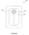
- treatment of a wound with negative pressure uses a wound dressing 10 capable of absorbing and storing wound exudate in conjunction with a flexible suction adapter 12.
- a wound packing material is optional, but may be desirable in certain wounds, for example deeper wounds.
- the wound packing material can be used in addition to the wound dressing 10.
- the wound packing material generally may comprise a porous and conformable material, for example foam (including reticulated foams), and gauze.
- the wound packing material is sized or shaped to fit within the wound site so as to fill any empty spaces.
- the wound dressing 10 may then be placed over the wound site and wound packing material overlying the wound site.
- a wound packing material When a wound packing material is used, once the wound dressing 10 is sealed over the wound site, negative pressure may be transmitted from a pump or other source of negative pressure through a flexible tubing 14 via the suction adapter 12 to the wound dressing 10, through the wound packing material, and finally to the wound site. This negative pressure draws wound exudate and other fluids or secretions away from the wound site.
- the suction adapter 12 preferably comprises a head 11 that is in fluidic communication with the dressing 10 as will be described in further detail below.
- the head 11 is illustrated here as being positioned at a corner of the dressing 10, but may also be positioned at any location on the dressing. For example, some embodiments may provide for a centrally or off-centered location not on an edge or corner of the dressing 10.
- the dressing 10 may comprise two or more suction adapters 12, each comprising one or more heads 11, in fluidic communication therewith.
- the head 11 may measure 30mm along its widest edge.
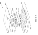
- certain embodiments of the wound dressing 10 may comprise a plurality of layers.
- a wound contact layer 203 with an upper surface 202 and a lower surface 200 may be configured to carry an adhesive on its lower surface 200 for sealing the wound dressing 10 to the wound site.
- a porous transmission layer 222 overlying the wound contact layer 203 may comprise a 3D knitted or 3D fabric material, and the transmission layer 222 may be configured to remain open upon application of negative pressure to the wound dressing. This facilitates fluid flow 204 through the transmission layer 222, although the transmission layer 222 does not retain a substantial amount of the fluid.
- An absorbent layer 220 overlying the transmission layer 222 may be configured for absorbing wound exudate.
- a moisture vapor permeable cover layer 218 overlays the absorbent layer 220.
- the wound contact layer 203 can be a polyurethane layer or polyethylene layer or other flexible layer which is perforated, for example via a hot pin process, laser ablation process, ultrasound process or in some other way or otherwise made permeable to liquid and gas.
- the perforations 104 are through holes in the wound contact layer which enables fluid to flow through the layer.
- the wound contact layer 203 may help prevent tissue ingrowth into the other material of the wound dressing 10.
- the perforations are small enough to meet this requirement but still allow fluid through. For example, perforations formed as slits or holes having a size ranging from 0.025 mm to 1.2 mm are considered small enough to help prevent tissue ingrowth into the wound dressing while allowing wound exudate to flow into the dressing.
- the wound contact layer 203 may help hold the whole wound dressing together and helps to create an air tight seal around the absorbent pad in order to maintain negative pressure at the wound.
- the wound contact layer 230 may also act as a carrier for an optional lower and upper adhesive layer (not shown).
- a lower pressure sensitive adhesive may be provided on the underside surface 200 of the wound dressing whilst an upper pressure sensitive adhesive layer may be provided on the upper surface 202 of the wound contact layer.
- the pressure sensitive adhesive which may be a silicone, hot melt, hydrocolloid or acrylic based adhesive or other such adhesives, may be formed on both sides or optionally on a selected one or none of the sides of the wound contact layer. When a lower pressure sensitive adhesive layer is utilized this may help adhere the wound dressing 10 to the skin around a wound site.
- the layer 222 of porous material is located above the wound contact layer 203.
- This porous layer, or transmission layer, 222 preferably allows transmission of fluid including liquid and gas away from a wound site into upper layers of the wound dressing.
- the transmission layer 222 ensures that an open air channel can be maintained to communicate negative pressure over the wound area even when the absorbent layer 220 has absorbed substantial amounts of exudates.
- the layer should remain open under the typical pressures that will be applied during negative pressure wound therapy as described above, so that the whole wound site sees an equalized negative pressure.
- the layer 222 is preferably formed of a material having a three dimensional structure.
- the transmission layer 222 may also comprise materials such foams, including open-cell foams such as polyethylene or polyurethane foam, meshes, non-woven materials, and fluid channels.
- the transmission layer 222 comprises a 3D polyester spacer fabric layer including a top layer (that is to say, a layer distal from the wound-bed in use) which is a 84/144 textured polyester, and a bottom layer (that is to say, a layer which lies proximate to the wound bed in use) which is a 10 denier flat polyester and a third layer formed sandwiched between these two layers which is a region defined by a knitted polyester viscose, cellulose or the like monofilament fiber. Other materials and other linear mass densities of fiber could of course be used.
- top spacer fabric thus has more filaments in a yarn used to form it than the number of filaments making up the yarn used to form the bottom spacer fabric layer.
- This differential between filament counts in the spaced apart layers helps control moisture flow across the transmission layer.
- the top layer is made from a yarn having more filaments than the yarn used in the bottom layer, liquid tends to be wicked along the top layer more than the bottom layer.
- this differential tends to draw liquid away from the wound bed and into a central region of the dressing where the absorbent layer 220 helps lock the liquid away or itself wicks the liquid onwards towards the cover layer where it can be transpired.
- the 3D fabric may be treated with a dry cleaning agent (such as, but not limited to, Perchloro Ethylene) to help remove any manufacturing products such as mineral oils, fats and/or waxes used previously which might interfere with the hydrophilic capabilities of the transmission layer.
- a dry cleaning agent such as, but not limited to, Perchloro Ethylene
- an additional manufacturing step can subsequently be carried in which the 3D spacer fabric is washed in a hydrophilic agent (such as, but not limited to, Feran Ice 30g/l available from the Rudolph Group). This process step helps ensure that the surface tension on the materials is so low that liquid such as water can enter the fabric as soon as it contacts the 3D knit fabric. This also aids in controlling the flow of the liquid insult component of any exudates.
- the layer 220 of absorbent material is provided above the transmission layer 222.
- the absorbent material which may be a foam or non-woven natural or synthetic material and which may optionally include or be super-absorbent material forms a reservoir for fluid, particularly liquid, removed from the wound site and draws those fluids towards a cover layer 218.
- the material of the absorbent layer 220 also prevents liquid collected in the wound dressing from flowing in a sloshing manner.
- the absorbent layer 220 also helps distribute fluid throughout the layer via a wicking action so that fluid is drawn from the wound site and stored throughout the absorbent layer 220. This helps prevent agglomeration in areas of the absorbent layer.
- the capacity of the absorbent material must be sufficient to manage the exudates flow rate of a wound when negative pressure is applied. Since in use the absorbent layer 220 experiences negative pressures the material of the absorbent layer 220 is chosen to absorb liquid under such circumstances. A number of materials exist that are able to absorb liquid when under negative pressure, for example superabsorber material.
- the absorbent layer 220 may typically be manufactured from ALLEVYNTM foam, Freudenberg 114-224-4 and/or Chem-PositeTM11C-450.
- the absorbent layer 220 is a layer of non-woven cellulose fibers having super-absorbent material in the form of dry particles dispersed throughout.
- Use of the cellulose fibers introduces fast wicking elements which help quickly and evenly distribute liquid taken up by the dressing.
- the juxtaposition of multiple strand-like fibers leads to strong capillary action in the fibrous pad which helps distribute liquid. In this way, the super-absorbent material is efficiently supplied with liquid.
- the wicking action also assists in bringing liquid into contact with the upper cover layer 218 to aid increase transpiration rates of the dressing.
- the wicking action also assists in delivering liquid downwards towards the wound bed when exudation slows or halts. This delivery process helps maintain the transmission layer and lower wound bed region in a moist state which helps prevent crusting within the dressing (which could lead to blockage) and helps maintain an environment optimized for wound healing.
- the absorbent layer 220 may be an air-laid material.
- Heat fusible fibers may optionally be used to assist in holding the structure of the pad together. It will be appreciated that rather than using super-absorbing particles or in addition to such use, super-absorbing fibers may be utilized according to certain embodiments of the present invention.
- An example of a suitable material is the Product Chem-PositeTM 11 C available from Emerging Technologies Inc. (ETi) in the USA.
- the absorbent layer 220 may include synthetic stable fibers and/or bi-component stable fibers and/or natural stable fibers and/or super-absorbent fibers. Fibers in the absorbent layer 220 may be secured together by latex bonding or thermal bonding or hydrogen bonding or a combination of any bonding technique or other securing mechanism.
- the absorbent layer 220 is formed by fibers which operate to lock super-absorbent particles within the absorbent layer 220. This helps ensure that super-absorbent particles do not move external to the absorbent layer 220 and towards an underlying wound bed.
- the absorbent layer 220 may comprise a layer of multiple fibers.
- the fibers are strand-like and made from cellulose, polyester, viscose or the like.
- dry absorbent particles are distributed throughout the absorbent layer ready for use.
- the absorbent layer 220 comprises a pad of cellulose fibers and a plurality of super absorbent particles.
- the absorbent layer is a non-woven layer of randomly orientated cellulose fibers.
- Super-absorber particles/fibers may be, for example, sodium polyacrylate or carbomethoxycellulose materials or the like or any material capable of absorbing many times its own weight in liquid.
- the material can absorb more than five times its own weight of 0.9% W/W saline, etc.
- the material can absorb more than 15 times its own weight of 0.9% W/W saline, etc.
- the material is capable of absorbing more than 20 times its own weight of 0.9% W/W saline, etc.
- the material is capable of absorbing more than 30 times its own weight of 0.9% W/W saline, etc.
- the particles of superabsorber are very hydrophilic and grab the fluid as it enters the dressing, swelling up on contact. Equilibrium is set up within the dressing core whereby moisture passes from the superabsorber into the dryer surrounding area and as it hits the top film the film switches and the fluid vapor starts to be transpired. A moisture gradient is established within the dressing to continually remove fluid from the wound bed and ensure the dressing does not become heavy with exudate.
- sealing surface 216 may be configured for sealing the suction adapter to the cover layer 218 of the wound dressing, and may comprise an adhesive or weld.
- the sealing surface 216 may be placed over an orifice in the cover layer with spacer elements 215 configured to create a gap between the filter 214 and the transmission layer 222.
- the sealing surface 216 may be positioned over an orifice in the cover layer 218 and an aperture in the absorbent layer 220, permitting the suction adapter 12 to provide air flow 206 through the transmission layer 222.
- the bridge 211 may comprise a first fluid passage 212 in communication with a source of negative pressure, the first fluid passage 212 comprising a porous material, such as a 3D knitted material, which may be the same or different than the porous layer 222 described previously.
- the bridge 211 is preferably encapsulated by at least one flexible film layer 208, 210 having a proximal and distal end and configured to surround the first fluid passage 212, the distal end of the flexible film being connected the sealing surface 216.
- the filter 214 is configured to substantially prevent wound exudate from entering the bridge, and spacer elements 215 are configured to prevent the suction adapter from contacting the transmission layer 222. These elements will be described in greater detail below.
- Some embodiments may further comprise an optional second fluid passage positioned above the first fluid passage 212.
- some embodiments may provide for an air leak may be disposed at the proximal end of the top layer that is configured to provide an air path into the first fluid passage 212 and dressing 10.
- the fluid passage 212 is constructed from a compliant material that is flexible and that also permits fluid to pass through it if the spacer is kinked or folded over.
- Suitable materials for the fluid passage 212 include without limitation foams, including open-cell foams such as polyethylene or polyurethane foam, meshes, 3D knitted fabrics, non-woven materials, and fluid channels.
- the fluid passage 212 may be constructed from materials similar to those described above in relation to the transmission layer 222.
- such materials used in the fluid passage 212 not only permit greater patient comfort, but may also provide greater kink resistance, such that the fluid passage 212 is still able to transfer fluid from the wound toward the source of negative pressure while being kinked or bent.
- the fluid passage 212 may be comprised of a wicking fabric, for example a knitted or woven spacer fabric (such as a knitted polyester 3D fabric, Baltex 7970®, or Gehring 879®) or a nonwoven fabric. These materials selected are preferably suited to channeling wound exudate away from the wound and for transmitting negative pressure and/or vented air to the wound site, and may also confer a degree of kinking or occlusion resistance to the fluid passage 212.
- the wicking fabric may have a three-dimensional structure, which in some cases may aid in wicking fluid or transmitting negative pressure.
- the wicking fabric may comprise several layers of material stacked or layered over each other, which may in some cases be useful in preventing the fluid passage 212 from collapsing under the application of negative pressure.
- the wicking fabric used in the fluid passage 212 may be between 1.5 mm and 6 mm; more preferably, the wicking fabric may be between 3 mm and 6 mm thick, and may be comprised of either one or several individual layers of wicking fabric.
- the fluid passage 212 may be between 1.2-3 mm thick, and preferably thicker than 1.5 mm.
- a suction adapter used with a dressing which retains liquid such as wound exudate may employ hydrophobic layers in the fluid passage 212, and only gases may travel through the fluid passage 212.
- the materials used in the system are preferably conformable and soft, which may help to avoid pressure ulcers and other complications which may result from a wound treatment system being pressed against the skin of a patient.
- the absorbent layer 220 includes at least one area 246, such as an edge or through hole, located so as to underlie the suction adapter 12 where the absorbent layer 220 is removed or not provided. It will be appreciated that multiple openings could alternatively be utilized. As shown in Figure 1A , this area 246 preferably underlies the point where the head 11 is in fluidic communication with the dressing. Additionally, should more than one suction adapter 12 be utilized according to certain embodiments, one or multiple openings may be made in the super-absorbent layer 220 in registration with each respective suction adapter. Although not essential to certain embodiments of the present invention the use of through holes in the super-absorbent layer 220 provide a fluid flow pathway which is particularly unhindered and this is useful in certain circumstances.
- the thickness of the layer itself will act as a stand-off separating any overlying layer from the upper surface (that is to say the surface facing away from a wound in use) of the transmission layer 222.
- An advantage of this is that the filter 214 is thus decoupled from the material of the transmission layer 222. This helps reduce the likelihood that the filter will be wetted out and thus will occlude and block further operation.
- each opening in the absorbent layer provides a fluid pathway between the transmission layer directly to the wound facing surface of the filter and then onwards into the interior of the suction adapter.
- the cover layer 218 extends across the width of the wound dressing, and is preferably gas impermeable, but moisture vapor permeable.
- the cover layer 218, which may for example be a polyurethane film (for example, Elastollan SP9109) having a pressure sensitive adhesive on one side, is preferably impermeable to gas and this layer thus operates to cover the wound and to seal a wound cavity over which the wound dressing is placed. In this way an effective chamber is made between the cover layer and a wound site where a negative pressure can be established.
- the cover layer 218 may for example be sealed to the wound contact layer 203 in a border region 200 around the circumference of the dressing, ensuring that no air is drawn in through the border area, for example via adhesive or welding techniques.
- the cover layer 218 protects the wound from external bacterial contamination (bacterial barrier) and allows liquid from wound exudates to be transferred through the layer and evaporated from the film outer surface.
- the cover layer 218 typically comprises two layers; a polyurethane film and an adhesive pattern spread onto the film.
- the polyurethane film is moisture vapor permeable and may be manufactured from a material that has an increased water transmission rate when wet.
- the absorbent layer 220 may be of a greater area than the transmission layer 222, such that the absorbent layer overlaps the edges of the transmission layer 222, thereby ensuring that the transmission layer does not contact the cover layer 218.
- This provides an outer channel of the absorbent layer 220 that is in direct contact with the wound contact layer 203, which aids more rapid absorption of exudates to the absorbent layer. Furthermore, this outer channel ensures that no liquid is able to pool around the circumference of the wound cavity, which may otherwise seep through the seal around the perimeter of the dressing leading to the formation of leaks.
- the transmission layer 222 In order to ensure that the air channel remains open when a vacuum is applied to the wound cavity, the transmission layer 222 must be sufficiently strong and non-compliant to resist the force due to the pressure differential. However, if this layer comes into contact with the relatively delicate cover layer 218, it may cause the formation of tears, holes, or pin-hole openings in the cover layer 218 which allow air to leak into the wound cavity. This may be a particular problem when a switchable type polyurethane film is used that becomes weaker when wet.
- the absorbent layer 220 is generally formed of a relatively soft, non-abrasive material compared to the material of the transmission layer 222 and therefore does not cause the formation of pin-hole openings in the cover layer. Thus by providing an absorbent layer 220 that is of greater area than the transmission layer 222 and that overlaps the edges of the transmission layer 222, contact between the transmission layer 222 and the cover layer 218 is prevented, avoiding the formation of openings in the cover layer 218.
- the absorbent layer 220 is positioned in fluid contact with the cover layer 218. As the absorbent layer 220 absorbs wound exudate, the exudate is drawn towards the cover layer 218, bringing the water component of the exudate into contact with the moisture vapor permeable cover layer. This water component is drawn into the cover layer itself and then evaporates from the top surface of the dressing. In this way, the water content of the wound exudate can be transpired from the dressing, reducing the volume of the remaining wound exudate that is to be absorbed by the absorbent layer 220, and increasing the time before the dressing becomes full and must be changed. This process of transpiration occurs even when negative pressure has been applied to the wound cavity, and it has been found that the pressure difference across the cover layer when a negative pressure is applied to the wound cavity has negligible impact on the moisture vapor transmission rate across the cover layer.
- An orifice 245 is provided in the cover film 218 to allow a negative pressure to be applied to the dressing 10.
- a suction adapter 12 may be sealed to the top of the cover film 218 over the orifice 245, and communicates negative pressure through the orifice 245.
- a length of tubing 14 may be coupled at a first end to the suction adapter 12 and at a second end to a pump unit (not shown) to allow fluids to be pumped out of the dressing.
- the suction adapter 12 may be adhered and sealed to the cover film 218 using an adhesive such as an acrylic, cyanoacrylate, epoxy, UV curable or hot melt adhesive.
- the suction adapter 12 may be separately attached to the cover film 218, while other embodiments may provide for the dressing 10 to be provided with the suction adapter 12 already attached to the cover film 218.
- the suction adapter 12 may be formed from a soft polymer, for example a polyethylene, a polyvinyl chloride, a silicone or polyurethane having a hardness of 30 to 90 on the Shore A scale.
- the area or through-hole 246 may be provided in the absorbent layer 220 beneath the orifice 245 such that the orifice is connected directly to the transmission layer 222. This allows the negative pressure applied to the suction adapter 12 to be communicated to the transmission layer 222 without passing through the absorbent layer 220. This ensures that the negative pressure applied to the wound site is not inhibited by the absorbent layer as it absorbs wound exudates.
- no aperture may be provided in the absorbent layer 220, or alternatively a plurality of apertures underlying the orifice 245 may be provided.
- one embodiment of the wound dressing 10 comprises an aperture 246 in the absorbent layer 10 situated underneath the suction adapter 12.
- a wound facing portion of the suction adapter 12 may thus come into contact with the transmission layer 222, which can thus aid in transmitting negative pressure to the wound site even when the absorbent layer 220 is filled with wound fluids.
- Some embodiments may have the cover layer 218 be at least partly adhered to the transmission layer 222.
- the aperture 246 is at least 1-2 mm larger than the diameter of the wound facing portion of the suction adapter 12, or the orifice 245.
- the filter element 214 is impermeable to liquids, but permeable to gases, and is provided to act as a liquid barrier and to ensure that no liquids are able to escape from the wound dressing 10.
- the filter element 214 may also function as a bacterial barrier.
- the pore size is 0.2 ⁇ m. Suitable materials for the filter material of the filter element 214 include 0.2 micron GoreTM expanded PTFE from the MMT range, PALL VersaporeTM 200R, and DonaldsonTM TX6628. Larger pore sizes can also be used but these may require a secondary filter layer to ensure full bioburden containment.
- the filter element can be attached or sealed to the port and/or the cover film 218 over the orifice 245.
- the filter element 214 may be molded into the suction adapter 12, or may be adhered to one or both of the top of the cover layer 218 and bottom of the suction adapter 12 using an adhesive such as, but not limited to, a UV cured adhesive.
- filter element 214 More generally a microporous membrane can be used which is a thin, flat sheet of polymeric material, this contains billions of microscopic pores. Depending upon the membrane chosen these pores can range in size from 0.01 to more than 10 micrometers. Microporous membranes are available in both hydrophilic (water filtering) and hydrophobic (water repellent) forms.
- filter element 214 comprises a support layer and an acrylic co-polymer membrane formed on the support layer.
- the wound dressing 10 according to certain embodiments of the present invention uses microporous hydrophobic membranes (MHMs). Numerous polymers may be employed to form MHMs.
- the MHMs may be formed from one or more of PTFE, polypropylene, PVDF and acrylic copolymer. All of these optional polymers can be treated in order to obtain specific surface characteristics that can be both hydrophobic and oleophobic. As such these will repel liquids with low surface tensions such as multi-vitamin infusions, lipids, surfactants, oils and organic solvents.
- MHMs block liquids whilst allowing air to flow through the membranes. They are also highly efficient air filters eliminating potentially infectious aerosols and particles. A single piece of MHM is well known as an option to replace mechanical valves or vents. Incorporation of MHMs can thus reduce product assembly costs improving profits and costs/benefit ratio to a patient.
- the filter element 214 may also include an odor absorbent material, for example activated charcoal, carbon fiber cloth or Vitec Carbotec-RT Q2003073 foam, or the like.
- an odor absorbent material may form a layer of the filter element 214 or may be sandwiched between microporous hydrophobic membranes within the filter element. The filter element 214 thus enables gas to be exhausted through the orifice 245. Liquid, particulates and pathogens however are contained in the dressing.
- the wound dressing 10 may comprise spacer elements 215 in conjunction with the suction adapter 12 and the filter 214. With the addition of such spacer elements 215 the suction adapter 12 and filter 214 may be supported out of direct contact with the absorbent layer 220 and/or the transmission layer 222.
- the absorbent layer 220 may also act as an additional spacer element to keep the filter 214 from contacting the transmission layer 222. Accordingly, with such a configuration contact of the filter 214 with the transmission layer 222 and wound fluids during use may thus be minimized.
- the suction adapter 12 and through hole 246 may be located in an off-center position as illustrated in Figures 1A-B . Such a location may permit the dressing 10 to be positioned onto a patient such that the suction adapter 12 is raised in relation to the remainder of the dressing 10. So positioned, the suction adapter 12 and the filter 214 may be less likely to come into contact with wound fluids that could prematurely occlude the filter 214 so as to impair the transmission of negative pressure to the wound site.
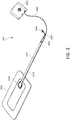
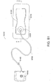
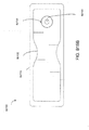
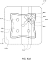
- FIG. 2 illustrates an embodiment of a negative pressure wound treatment system 5501 employing a wound dressing 5500 in conjunction with a flexible suction adapter 5512.
- the wound dressing 5500 may be similar to the dressings illustrated in FIGS 1A-B .
- the flexible suction adapter 5512 may comprise a bridge 5502 having a proximal end 5503 and a distal end 5505 and an applicator 5504 at the distal end 5505 of the bridge 5502.
- a connector 5504 is preferably disposed at the proximal end 5503 of the bridge 5502.
- a cap 5536 may be provided with the system 5501 (and can in some cases, as illustrated, be attached to the connector 5504). The cap 5536 can be useful in preventing fluids from leaking out of the proximal end 5503.
- the system 5501 may include a source of negative pressure such as a pump or negative pressure unit 5534 capable of supplying negative pressure.
- the pump also preferably comprises a canister or other container for the storage of wound exudates and other fluids that may be removed from the wound.
- this pump 5534 can be a PICOTM pump, as sold by Smith & Nephew.
- the pump 5534 may be connected to the connector 5504 via a tube 5540.
- the dressing 5500 is placed over a suitably-prepared wound, which may in some cases be filled with a wound packing material such as foam or gauze. Subsequently, with the pump 5534 connected via the tube 5540 to the connector 5504, the pump is activated, thereby supplying negative pressure to the wound. Application of negative pressure may be applied until a desired level of healing of the wound 5530 is achieved.
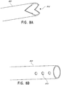
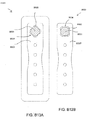
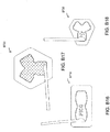
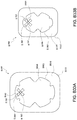
- FIGS. 3A-C illustrate various embodiments of the head 11 of the suction adapter 12.
- the suction adapter 12 illustrated in FIGS. 1A-C is enlarged at the distal end to be placed over the orifice in the cover layer 218 and the aperture in the absorbent layer 220, and may form a "teardrop" or other enlarged shape.
- FIG. 3A illustrates a suction adapter 12 with a substantially triangular head 11.
- FIG. 3B illustrates a suction adapter 12 with a substantially pentagonal head 11.
- FIG. 3A illustrates a suction adapter 12 with a substantially circular head 11.
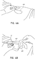
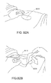
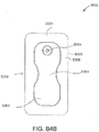
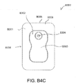
- Figures 4A-D illustrate the use of an embodiment of a negative pressure therapy wound treatment system being used to treat a wound site on a patient.
- Figure 4A shows a wound site 490 being cleaned and prepared for treatment.
- the healthy skin surrounding the wound site 490 is preferably cleaned and excess hair removed or shaved.
- the wound site 490 may also be irrigated with sterile saline solution if necessary.
- a skin protectant may be applied to the skin surrounding the wound site 490.
- a wound packing material such as foam or gauze, may be placed in the wound site 490. This may be preferable if the wound site 490 is a deeper wound.
- the wound dressing 400 may be positioned and placed over the wound site 490.
- the wound dressing 400 may be similar to the wound dressing 10 described above in relation to FIGS. 1A-B .
- the wound dressing 400 is placed with the wound contact layer 203 (illustrated in FIGS. 1A-B ) over and/or in contact with the wound site 490.
- an adhesive layer is provided on the lower surface 200 of the wound contact layer 203, which may in some cases be protected by an optional release layer to be removed prior to placement of the wound dressing 400 over the wound site 490.
- the dressing 400 is positioned such that the suction adapter 12 is in a raised position with respect to the remainder of the dressing 400 so as to avoid fluid pooling around the port.
- the dressing 400 is positioned so that the suction adapter 12 is not directly overlying the wound, and is level with or at a higher point than the wound.
- the edges of the dressing 400 are preferably smoothed over to avoid creases or folds.
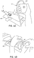
- the dressing 400 is connected to the pump 420.
- the pump 420 is configured to apply negative pressure to the wound site via the dressing 400, and typically through a conduit.
- a connector may be used to join the conduit from the dressing 400 to the pump 420.
- the dressing 400 may in some embodiments partially collapse and present a wrinkled appearance as a result of the evacuation of some or all of the air underneath the dressing 400.
- the pump 420 may be configured to detect if any leaks are present in the dressing 400, such as at the interface between the dressing 400 and the skin surrounding the wound site 490. Should a leak be found, such leak is preferably remedied prior to continuing treatment.
- fixation strips 495 may also be attached around the edges of the dressing 400. Such fixation strips 495 may be advantageous in some situations so as to provide additional sealing against the skin of the patient surrounding the wound site 490. For example, the fixation strips 495 may provide additional sealing for when a patient is more mobile. In some cases, the fixation strips 495 may be used prior to activation of the pump 420, particularly if the dressing 400 is placed over a difficult to reach or contoured area.
- Treatment of the wound site 490 preferably continues until the wound has reached a desired level of healing.
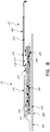
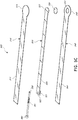
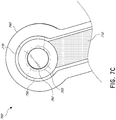
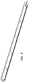
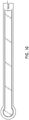
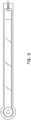
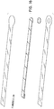
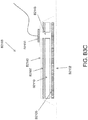
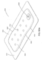
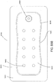
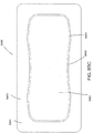
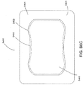
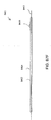
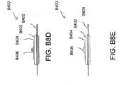
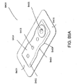
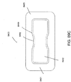
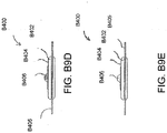
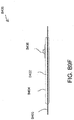
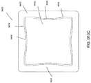
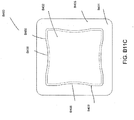
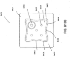
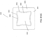
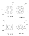
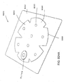
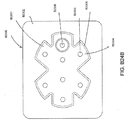
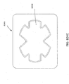
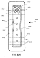
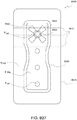
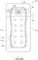
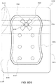
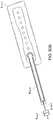
- Figures 5A-B illustrate an embodiment of a flexible port or fluidic connector 500.
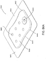
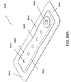
- Figure 5C illustrates a perspective exploded view the fluidic connector 500 that may be used to connect a wound dressing to a source of negative pressure.
- the port 500 comprises a top layer 510, a spacer layer 520, a filter element 530, a bottom layer 540, and a conduit 550.
- the conduit optionally comprises a connector 560.
- the distal end of the port 500 (the end connectable to the dressing) is depicted as having an enlarged circular shape, although it will be appreciated that any suitable shape may be used and that the distal end need not be enlarged.
- the distal end can have any of the shapes shown in Figures 3A-3C above.
- the distal end can also have the shape shown in Figures B23A and B23B, discussed below.
- the bottom layer 540 may comprise an elongate bridge portion 544, an enlarged (e.g., rounded or circular) sealing portion 545, and an orifice 541.
- a plurality of orifices may be provided in the bottom layer.
- Some embodiments of the rounded sealing portion 545 may comprise a layer of adhesive, for example a pressure sensitive adhesive, on the lower surface for use in sealing the port 500 to a dressing.
- the port may be sealed to a cover layer of the dressing.
- the orifice 541 in the bottom layer 540 of the port 500 may be aligned with an orifice in the cover layer of the dressing in order to transmit negative pressure through the dressing and into a wound site.
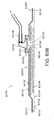
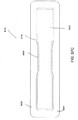
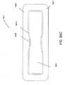
- the top layer 515 may be substantially the same shape as the bottom layer in that it comprises an elongate bridge 514 and an enlarged (e.g., rounded or circular) portion 545.
- the top layer 515 and the bottom layer 545 may be sealed together, for example by heat welding.
- the bottom layer 545 may be substantially flat and the top layer 515 may be slightly larger than the bottom layer 545 in order to accommodate the height of the spacer layer 520 and seal to the bottom layer 545.
- the top layer 515 and bottom layer 3145 may be substantially the same size, and the layers may be sealed together approximately at the middle of the height of the spacer layer 520.
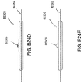
- the elongate bridge portions 544, 514 may have a length of 10 cm (or about 10 cm) or more, more preferably a length of 20 cm (or about 20 cm) or more and in some embodiments, may be about 69 cm (or 27 cm) long.
- Some embodiments of the entire flexible port, from a proximalmost edge of the top and bottom layers to a distalmost edge of the top and bottom layers, may be between 20 cm and 80 cm (or about 20 cm to about 80 cm) long, more preferably about 60 cm and 80 cm (or between about 60 cm and about 80 cm) long, for example about 70 cm long.
- the elongate bridge portions may have a width of between 1 cm and 4 cm (or between about 1 cm and about 4 cm), and in one embodiment, is about 2.5 cm wide.
- the ratio of the length of the elongate bridge portions 544, 514 to their widths may in some embodiments exceed 6:1, and may more preferably exceed 8:1 or even 10:1.
- the diameter of the circular portion 545, 515 may be about 3.5 cm in some embodiments.
- the bottom and top layers may comprise at least one layer of a flexible film, and in some embodiments may be transparent. Some embodiments of the bottom layer 540 and top layer 515 may be polyurethane, and may be liquid impermeable.
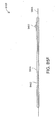
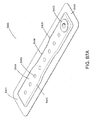
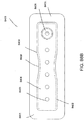
- the port 500 may comprise a spacer layer 520, such as the 3D fabric discussed above, positioned between the lower layer 540 and the top layer 510.
- the spacer layer 520 may be made of any suitable material, for example material resistant to collapsing in at least one direction, thereby enabling effective transmission of negative pressure therethrough.
- some embodiments of the spacer layer 520 may comprise a fabric configured for lateral wicking of fluid, which may comprise viscose, polyester, polypropylene, cellulose, or a combination of some or all of these, and the material may be needle-punched.
- spacer layer 520 may comprise polyethylene in the range of 40-160 grams per square meter (gsm) (or about 40 to about 160 gsm), for example 80 (or about 80) gsm. Such materials may be constructed so as to resist compression under the levels of negative pressure commonly applied during negative pressure therapy.
- the spacer layer 520 may comprise an elongate bridge portion 524, an enlarged (e.g., rounded or circular) portion 525, and may optionally include a fold 521.
- the elongate bridge portion may have dimensions in the same ranges as the bridge portions of the upper and lower layers described above though slightly smaller, and in one embodiment is about 25.5 cm long and 1.5 cm wide.
- the diameter of the circular portion 525 may be slightly smaller than the diameters of the enlarged ends 545, 515, and in one embodiment is about 2 cm.
- the spacer layer 520 may have adhesive on one or both of its proximal and distal ends (e.g., one or more dabs of adhesive) in order to secure the spacer layer 520 to the top layer 510 and/or the bottom layer 540. Adhesive may also be provided along a portion or the entire length of the spacer layer. In other embodiments, the spacer layer 520 may be freely movable within the sealed chamber of the top and bottom layers.
- the fold 521 of the spacer layer may make the end of the port 500 softer and therefore more comfortable for a patient, and may also help prevent the conduit 550 from blockage.
- the fold 521 may further protect the end of the conduit 550 from being occluded by the top or bottom layers.
- the fold 521 may, in some embodiments, be between 1 cm and 3 cm (or between about 1 cm and about 3 cm) long, and in one embodiment is 2 cm (or about 2 cm) long.
- the spacer layer may be folded underneath itself, that is toward the bottom layer 540, and in other embodiments may be folded upward toward the top layer 510. Other embodiments of the spacer layer 520 may contain no fold.
- a slot or channel 522 may extend perpendicularly away from the proximal end of the fold 521, and the conduit 550 may rest in the slot or channel 522.
- the slot 522 may extend through one layer of the fold, and in others it may extend through both layers of the fold.
- the slot 522 may, in some embodiments, be 1 cm (or about 1 cm) long.
- Some embodiments may instead employ a circular or elliptical hole in the fold 521. The hole may face proximally so that the conduit 550 may be inserted into the hole and rest between the folded layers of spacer fabric.
- the conduit 550 may be adhered to the material of the fold 3521, while in other embodiments it may not.
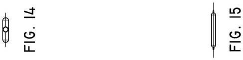
- the port 500 may have a filter element 530 located adjacent the orifice 541, and as illustrated is located between the lower layer 540 and the spacer layer 520.
- the filter element 530 is impermeable to liquids, but permeable to gases.
- the filter element may be similar to the element described above with respect to Figure 1B , and as illustrated may have a round or disc shape.
- the filter element 530 can act as a liquid barrier, to substantially prevent or inhibit liquids from escaping from the wound dressing, as well as an odor barrier.
- the filter element 530 may also function as a bacterial barrier.
- the pore size of the filter element 530 can be approximately 0.2 ⁇ m.
- Suitable materials for the filter material of the filter element include 0.2 micron GoreTM expanded PTFE from the MMT range, PALL VersaporeTM 200R, and DonaldsonTM TX6628.
- the filter element 530 thus enables gas to be exhausted through the orifice. Liquid, particulates and pathogens however are contained in the dressing. Larger pore sizes can also be used but these may require a secondary filter layer to ensure full bioburden containment.
- the filter element 530 may be adhered to one or both of top surface of the bottom layer 540 and the bottom surface of the spacer layer 520 using an adhesive such as, but not limited to, a UV cured adhesive. In other embodiments, the filter 530 may be welded to the inside of the spacer layer 520 and to the top surface of the bottom layer 540. The filter may also be provided adjacent the orifice on a lower surface of the bottom layer 540. Other possible details regarding the filter are disclosed in U.S. Patent Pub. No. 2011/0282309 .
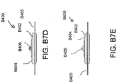
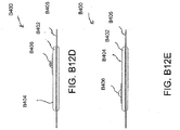
- the proximal end of the port 500 may be connected to the distal end of a conduit 550.
- the conduit 550 may comprise one or more circular ribs 551.
- the ribs 551 may be formed in the conduit 550 by grooves in a mold during the manufacturing of the conduit. During heat welding of the upper and lower layers 515, 545 melted material from those layers may flow around the ribs 551, advantageously providing a stronger connection between the conduit 550 and the layers. As a result, it may be more difficult to dislodge the conduit 550 out from between the layers during use of the port 500.
- the proximal end of the conduit 550 may be optionally attached to a connector 560.
- the connector 560 may be used to connect the port 500 to a source of negative pressure, or in some embodiments to an extension conduit which may in turn be connected to a source of negative pressure.
- the proximal end of the conduit 550 which is inserted into the spacer fabric 520, may be shaped in such a way to reduce the possibility of occlusion.
- some embodiments may have a triangular portion cut out of the end of the conduit, and other embodiments may have a plurality of holes therethrough.
- Figure 6 illustrates an embodiment of a wound dressing 610 with a flexible port 620 such as described above with respect to Figures 5A-C attached to the dressing.
- the port 620 may be the port described above in Figures 5A-C .
- the port 620 may comprise a conduit 630 and a connector 640 for connecting the port to a source of negative pressure or to an extension conduit.
- the port 620 may be connected over a circular window in the obscuring layer of the dressing 610, in other embodiments the port 620 may be connected over a maltese cross in the obscuring layer.
- the maltese cross may be of a larger diameter than the port 620 and may be at least partially viewable after the port 620 is attached to the dressing 610.
- Figure 7A depicts a perspective view of a flexible port 700 of the same design as shown with respect to Figures 5A-C .
- the port 700 comprises spacer fabric 710, wherein the proximal end of spacer fabric 710 comprises a fold 720, at least one layer of flexible film 740, an enlarged rounded distal end 715, a conduit 760, and a connector 780.
- the components of port 700 may have similar properties to the components of Figures 5A-C , described above.
- Figure 7B illustrates a close up view of an embodiment of the proximal end of the flexible port 700.
- the port 700 comprises spacer fabric 710 inside a sealed chamber 770 between layers of flexible film 740.
- the end of the spacer fabric 710 comprises a fold 720.
- At the proximal end of the fold there may be a hole 730 through the fabric for inserting the conduit 760.
- the conduit 760 may rest between the folded portions of the spacer fabric.
- the conduit 760 comprises a plurality of ribs 750, which may, as described above with respect to Figures 5A-C , act to secure the conduit 760 between the layers of flexible film 740.
- Figure 7C illustrates a close up view of the bottom of the distal end of the flexible port 700.
- the bottom of the port 700 comprises an orifice 792 for transmitting negative pressure to a dressing to which the port may be attached.
- the port 700 comprises a filter 790, which may have similar properties to the filters described above with respect to Figures 1B and 5A-C .
- the filter 790 may have a portion 795 which is adhered to the flexible film 740 around the perimeter of the orifice 795, thereby substantially maintaining the seal of chamber 770.
- Figures 8A and 8B illustrate embodiments of the distal end of a conduit 800 which may be part of any of the port embodiments described above.
- the distal end may be shaped in such a way to reduce the possibility of occlusion.
- the embodiment of Figure 8A may have a triangular portion 810 cut out of the end of the conduit, and other embodiments may have a plurality of holes therethrough.
- Figures 9-16 depict various views of an ornamental design of one embodiment of a flexible port as described herein. As will be evident from the various embodiments described herein, functionally equivalent alternative designs of such a flexible port are available, and the configuration of the design illustrated in Figures 9-16 was at least in part the result of aesthetic and ornamental considerations.
- the solid lines indicate the incorporation of the entire structure as part of one embodiment of an ornamental design for the flexible port. In the case of a partial flexible port design, any number of the solid lines may instead be depicted as broken lines to indicate that a component illustrated in broken lines is not part of that embodiment of the ornamental design.
- a wound treatment apparatus for treatment of a wound site comprises: a wound dressing comprising: an absorbent layer configured to retain fluid, a backing layer above the absorbent layer, and an obscuring layer configured to at least partly visually obscure fluid within the absorbent layer; and a fluidic connector configured to transmit negative pressure from a negative pressure source to the wound dressing for the application of topical negative pressure at the wound site.
- the obscuring layer is above or below the backing layer.
- the obscuring layer may configured to at least partially visually obscure fluid contained within the absorbent layer.
- the obscuring layer may comprise at least one viewing window configured to allow a visual determination of the saturation level of the absorbent layer.
- the at least one viewing window may comprise at least one aperture made through the obscuring layer.
- the at least one viewing window may comprise at least one uncolored region of the obscuring layer.
- the viewing window may comprise an array of dots.
- the array of dots may be distributed in a straight line of dots, the straight line of dots being positioned on a center line along a length of the absorbent layer.
- the straight line of dots may comprise an array of three dots.
- the straight line of dots may comprise an array of five dots.
- the straight line of dots may comprise an array of eight dots.
- the array of dots may be distributed in two straight lines of dots, the two straight lines of dots positioned to be an equal distance from a center line along a length of the absorbent layer, the two straight lines of dots having an equal number of dots.
- the two straight lines of dots may comprise an array of three dots.
- the two straight lines of dots may comprise an array of five dots.
- the array of dots may be distributed regularly over the obscuring layer to enable assessment of wound exudate spread.
- the viewing window may be selected from the group consisting of a graphical element or a typographical element.
- the obscuring layer may comprise an auxiliary compound, wherein the auxiliary compound may comprise activated charcoal configured to absorb odors and configured to color or tint the obscuring layer.
- the fluidic connector may comprise an obscuring element configured to substantially visually obscure wound exudate.
- Some embodiments may further comprise an acquisition distribution layer between the wound contact layer and the absorbent material.
- the absorbent layer may comprise cellulose fibers and between 40% and 80% (or between about 40% and about 80%) superabsorbent particles.
- the obscuring layer, in a dry state may be configured to yield a CIE y value of .4 or less and a CIE x value of .5 or less on a CIE x, y chromacity diagram.
- the obscuring layer, in a dry state may have a color of Bg, gB, B, pB, bP, P, rP, pPk, RP, O, rO, or yO on a CIE x, y chromacity diagram.
- the wound dressing further comprises an orifice in the backing layer, the orifice configured to communicate negative pressure to the wound site.
- the orifice may comprise at least one orifice viewing window configured to be positioned adjacent to the orifice in the backing layer, the orifice viewing window configured to allow a visual determination of the saturation level of the absorbent layer adjacent to the orifice.
- the orifice viewing window may be cross-shaped.
- the wound dressing may comprise a first length corresponding to a first edge of a wound dressing and a first width corresponding to a second edge of the wound dressing, a first x axis runs along the first width and a first y axis runs along the first length, wherein the first x axis and the first y axis are in a perpendicular alignment.
- the viewing window may comprise a first arm and a second arm, the first arm of the viewing window define a second length and the second arm defines a second width, a second x axis runs along the second width and a second y axis runs along the second length, wherein the second x axis and the second y axis are in a perpendicular alignment.
- the second x axis and second y axis of the viewing window is offset from the first x axis and the first y axis of the absorbent layer.
- the second x axis and second y axis of the viewing window may be aligned with the first x axis and the first y axis of the absorbent layer.
- the cross-shaped transparent layer may comprise flared ends.
- the fluidic connector may be configured to transmit air.
- the fluidic connector may comprise a filter, the filter configured to block fluid transport past itself.
- the fluidic connector may comprise a secondary air leak channel, the secondary air leak channel configured to allow a flow of ambient air to the wound site.
- the secondary air leak channel may comprise a filter.
- the fluidic connector may comprise a soft fluidic connector.
- the soft fluidic connector may comprise a three dimensional fabric.
- the three dimensional fabric is configured to transmit therapeutic levels of negative pressure while an external pressure up to 2 kg/cm 2 is applied thereto.
- the soft fluidic connector may be configured to be connected to a tube in fluid communication with the vacuum source.
- the soft fluidic connector may be configured to be connected directly to the vacuum source.
- the soft fluidic connector may comprise an enlarged distal end, the enlarged distal end configured to be connected to the wound dressing.
- the apparatus may further comprise a tube connected to the fluidic connector.
- the apparatus may further comprise a pump in fluid communication with the fluidic connector.
- the absorbent layer comprises two or more lobes.
- a wound treatment apparatus for treatment of a wound site comprises: a wound dressing configured to be positioned over a wound site, the wound dressing comprising: a backing layer having an upper surface and a lower surface and defining a perimeter configured to be positioned over skin surrounding the wound site, the backing layer including an opening; a wound contact layer adhered to the lower surface of the backing layer, the wound contact layer comprising an adhesive on a lower surface thereof; an absorbent material positioned between the backing layer and the wound contact layer, wherein the absorbent material comprises a vertical hole positioned below the opening in the backing layer; an obscuring layer positioned at least partially over the absorbent material, wherein the obscuring layer comprises a vertical hole positioned between the opening in the backing layer and the vertical hole in the absorbent material; one or more viewing windows extending through the obscuring layer configured to allow visualization of wound exudate in the absorbent material; and a port positioned over the opening in the backing layer configured to transmit negative pressure through the port for the application of topical negative pressure at the wound site.
- the backing layer is transparent or translucent.
- the backing layer may define a perimeter with a rectangular or a square shape.
- the wound contact layer may be adhered to the lower surface of the backing layer along the perimeter of the backing layer.
- the hole in the obscuring layer may have a different diameter than the hole in the absorbent material or the opening in the backing layer.
- the one or more viewing windows may be arranged in a repeating pattern across the obscuring layer.
- the one or more viewing windows may have a circular shape.
- Some embodiments may further comprise an acquisition distribution layer between the wound contact layer and the absorbent material.
- the absorbent layer may comprise cellulose fibers and between 40% and 80% (or between about 40% and about 80%) superabsorbent particles.
- the obscuring layer, in a dry state, may be configured to yield a color of Bg, gB, B, pB, bP, P, rP, pPk, RP, O, rO, or yO on the CIE x, y chromacity diagram.
- Some embodiments further comprise a transmission layer between the absorbent material and the wound contact layer.
- the apparatus further comprises a hydrophobic filter positioned in or below the port.
- the absorbent material may have a longitudinal length and a transverse width, wherein the length is greater than the width, and wherein the width of the absorbent material narrows in a central portion along the longitudinal length of the absorbent material.
- the obscuring layer may have substantially the same perimeter shape as the absorbent material.
- the apparatus may further comprise a pump
- a wound treatment apparatus for treatment of a wound site comprises: a wound dressing configured to be conformable to a nonplanar wound comprising: an absorbent layer comprising a contoured shape, the contoured shape comprising a substantially rectangular body with a waisted portion, and a backing layer above the absorbent layer; and a fluidic connector configured to transmit negative pressure from a negative pressure source to the wound dressing for the application of topical negative pressure at a wound site.
- Some embodiments may further comprise a wound contact layer.
- the backing layer may be rectangular.
- the negative pressure source is a pump.
- the wound dressing has a longer axis and a shorter axis, and wherein the waisted portion configured to be on the longer axis.
- the apparatus may further comprise an obscuring layer configured to at least partly visually obscure fluid within the absorbent layer.
- the obscuring layer may comprise at least one viewing window configured to allow a visual determination of the saturation level of the absorbent layer.
- the viewing window may comprise an array of dots.
- the fluidic connector may be located along a side or corner of the rectangular body.
- Some embodiments may further comprise an acquisition distribution layer between the wound contact layer and the absorbent material.
- the absorbent layer may comprise cellulose fibers and 40%-80% (or about 40% to about 80%) superabsorbent particles.
- the obscuring layer, in a dry state, may be configured to yield a color of Bg, gB, B, pB, bP, P, rP, pPk, RP, O, rO, or yO on the CIE x, y chromacity diagram.
- an apparatus for dressing a wound for the application of topical negative pressure at a wound site comprises: an absorbent layer having one or more slits extending at least partially across the width of the absorbent layer; and a backing layer above the absorbent layer, the backing layer having an orifice for communicating negative pressure to the wound site, wherein the orifice is positioned over a portion of the absorbent layer having no slits.
- the one or more slits comprise one or more concentric arcs.
- a wound treatment apparatus comprises: a wound dressing configured to be conformable to a nonplanar wound comprising: an absorbent layer above the contact layer, the absorbent layer comprising a contoured shape, the contoured shape comprising two or more lobes, and a backing layer above the absorbent layer.
- the wound treatment apparatus comprises a pump.
- the wound dressing may comprise a fluidic connector configured to transmit negative pressure from a pump to the wound dressing for the application of topical negative pressure at a wound site.
- the wound dressing may also comprise a wound-facing contact layer.
- the contoured shape may comprise three lobes.
- the contoured shape may comprise four lobes.
- the two or more lobes may comprise rounded projections.
- the apparatus may comprise two or more lobes flared lobes.
- the contoured shape may be oval-shaped.
- the contoured shape may comprise six lobes.
- the apparatus may further comprise an obscuring layer disposed so as to obscure the absorbent layer.
- the apparatus may further comprise an obscuring layer configured to at least partly visually obscure fluid within the absorbent layer.
- the obscuring layer may comprise at least one viewing window configured to allow a visual determination of the saturation level of the absorbent layer.
- the viewing window may comprise an array of dots.
- an apparatus for dressing a wound for the application of topical negative pressure at a wound site comprises: a wound contact layer; an acquisition distribution layer above the transmission layer; an absorbent layer over the acquisition and distribution layer, the absorbent layer comprising a matrix and superabsorbing particles within the matrix; and a backing layer above the absorbent layer.
- Some embodiments of the apparatus may further comprise a transmission layer between the wound contact layer and the acquisition distribution layer.
- the acquisition distribution layer may comprise viscose, polyester, polypropylene, cellulose, polyethylene or a combination of some or all of these materials.
- the absorbent layer may comprise between 30% and 40% (or between about 30% and about 40%) cellulose matrix and between 60% and 70% (or between about 60% and about 70%) superabsorbing polymers.
- the backing layer may be transparent or translucent.
- Some embodiments may further comprise an obscuring layer between the absorbent layer and the backing layer.
- There may be one or more viewing windows in the obscuring layer.
- At least the obscuring layer may be shaped with a narrowed central portion along its length.
- the obscuring layer may comprise two rows of three viewing windows, one row of three viewing windows, one row of eight viewing windows, two rows of five viewing windows, or one row of five viewing windows.
- At least the obscuring layer may be shaped with a narrowed central portion along both its width and its length.
- the obscuring layer may comprise a 3 x 3 array of viewing window or a quincunx array of viewing windows.
- at least the obscuring layer may comprise a six-lobed shape.
- the absorbent layer and acquisition distribution layer may be substantially the same shape as the obscuring layer.
- the obscuring layer may further comprise a cross or maltese cross shaped hole over which a fluidic connector for transmitting negative pressure may be connected.
- the apparatus may further comprise a fluidic connector configured to connect the backing layer to a source of negative pressure.
- an apparatus for dressing a wound for the application of topical negative pressure at a wound site comprises: an absorbent layer configured to retain fluid, a backing layer above the absorbent layer, and an obscuring layer configured to at least partly visually obscure fluid within the absorbent layer, wherein the obscuring layer, in a dry state, is configured to yield a color of Bg, gB, B, pB, bP, P, rP, pPk, RP, O, rO, or yO on the CIE x, y chromacity diagram.
- Some embodiments may further comprise one or more viewing windows in the backing layer.
- At least the obscuring layer may be shaped with a narrowed central portion along its length.
- the obscuring layer may comprise a 3 x 3 array of viewing window or a quincunx array of viewing windows.
- at least the obscuring layer may comprise a six-lobed shape.
- the absorbent layer and acquisition distribution layer may be substantially the same shape as the obscuring layer.
- the obscuring layer may further comprise a cross or maltese cross shaped hole over which a fluidic connector for transmitting negative pressure may be connected.
- the apparatus may further comprise a fluidic connector configured to connect the backing layer to a source of negative pressure.
- Figure B1 illustrates an embodiment of a TNP wound treatment system B100 comprising a wound dressing B110 in combination with a pump B150.
- the wound dressing B110 can be any wound dressing embodiment disclosed herein including without limitation dressing embodiment or have any combination of features of any number of wound dressing embodiments disclosed herein.
- the dressing B110 may be placed over a wound as described previously, and a conduit B130 may then be connected to the port B120, although in some embodiments the dressing B101 may be provided with at least a portion of the conduit B130 preattached to the port B120.
- the dressing B110 is provided as a single article with all wound dressing elements (including the port B120) pre-attached and integrated into a single unit.
- the wound dressing B110 may then be connected, via the conduit B130, to a source of negative pressure such as the pump B150.
- the pump B150 can be miniaturized and portable, although larger conventional pumps may also be used with the dressing B110.
- the pump B150 may be attached or mounted onto or adjacent the dressing B110.
- a connector B140 may also be provided so as to permit the conduit B130 leading to the wound dressing B110 to be disconnected from the pump, which may be useful for example during dressing changes.
- Figures B2A-D illustrate the use of an embodiment of a TNP wound treatment system being used to treat a wound site on a patient.
- Figure B2A shows a wound site B200 being cleaned and prepared for treatment.
- the healthy skin surrounding the wound site B200 is preferably cleaned and excess hair removed or shaved.
- the wound site B200 may also be irrigated with sterile saline solution if necessary.
- a skin protectant may be applied to the skin surrounding the wound site B200.
- a wound packing material such as foam or gauze, may be placed in the wound site B200. This may be preferable if the wound site B200 is a deeper wound.
- the wound dressing B110 may be positioned and placed over the wound site B200.
- the wound dressing B110 is placed with the wound contact layer B2102 over and/or in contact with the wound site B200.
- an adhesive layer is provided on the lower surface B2101 of the wound contact layer B2102, which may in some cases be protected by an optional release layer to be removed prior to placement of the wound dressing B110 over the wound site B200.
- the dressing B110 is positioned such that the port B2150 is in a raised position with respect to the remainder of the dressing B110 so as to avoid fluid pooling around the port.
- the dressing B110 is positioned so that the port B2150 is not directly overlying the wound, and is level with or at a higher point than the wound.
- the edges of the dressing B110 are preferably smoothed over to avoid creases or folds.
- the dressing B110 is connected to the pump B150.
- the pump B150 is configured to apply negative pressure to the wound site via the dressing B110, and typically through a conduit.
- a connector may be used to join the conduit from the dressing B110 to the pump B150.
- the dressing B110 may, in some embodiments, partially collapse and present a wrinkled appearance as a result of the evacuation of some or all of the air underneath the dressing B110.
- the pump B150 may be configured to detect if any leaks are present in the dressing B110, such as at the interface between the dressing B110 and the skin surrounding the wound site B200. Should a leak be found, such leak is preferably remedied prior to continuing treatment.
- fixation strips B210 may also be attached around the edges of the dressing B110. Such fixation strips B210 may be advantageous in some situations so as to provide additional sealing against the skin of the patient surrounding the wound site B200. For example, the fixation strips B210 may provide additional sealing for when a patient is more mobile. In some cases, the fixation strips B210 may be used prior to activation of the pump B150, particularly if the dressing B110 is placed over a difficult to reach or contoured area.
- Treatment of the wound site B200 preferably continues until the wound has reached a desired level of healing.
- Figures B3A-C illustrate cross-sections through a wound dressing B2100 similar to the wound dressing of Figure B1 according to an embodiment of the disclosure.
- a view from above the wound dressing B2100 is illustrated in Figure B1 with the line A-A indicating the location of the cross-section shown in Figures B3A and B3B.
- the wound dressing B2100 which can alternatively be any wound dressing embodiment disclosed herein including without limitation wound dressing B110 or any combination of features of any number of wound dressing embodiments disclosed herein, can be located over a wound site to be treated.
- the dressing B2100 may be placed to as to form a sealed cavity over the wound site.
- the dressing B2100 comprises a backing layer B2140 attached to a wound contact layer B2102, both of which are described in greater detail below.
- These two layers B2140, B2102 are preferably joined or sealed together so as to define an interior space or chamber.
- This interior space or chamber may comprise additional structures that may be adapted to distribute or transmit negative pressure, store wound exudate and other fluids removed from the wound, and other functions which will be explained in greater detail below. Examples of such structures, described below, include a transmission layer B2105 and an absorbent layer B2110.
- a lower surface B2101 of the wound dressing B2100 may be provided with an optional wound contact layer B2102.
- the wound contact layer B2102 can be a polyurethane layer or polyethylene layer or other flexible layer which is perforated, for example via a hot pin process, laser ablation process, ultrasound process or in some other way or otherwise made permeable to liquid and gas.
- the wound contact layer B2102 has a lower surface B2101 and an upper surface B2103.
- the perforations B2104 preferably comprise through holes in the wound contact layer B2102 which enable fluid to flow through the layer B2102.
- the wound contact layer B2102 helps prevent tissue ingrowth into the other material of the wound dressing.
- the perforations are small enough to meet this requirement while still allowing fluid to flow therethrough.
- perforations formed as slits or holes having a size ranging from 0.025 mm to 1.2 mm are considered small enough to help prevent tissue ingrowth into the wound dressing while allowing wound exudate to flow into the dressing.
- the wound contact layer B2102 may help maintain the integrity of the entire dressing B2100 while also creating an air tight seal around the absorbent pad in order to maintain negative pressure at the wound.
- the wound contact layer B2102 may also act as a carrier for an optional lower and upper adhesive layer (not shown).
- a lower pressure sensitive adhesive may be provided on the lower surface B2101 of the wound dressing B2100 whilst an upper pressure sensitive adhesive layer may be provided on the upper surface B2103 of the wound contact layer.
- the pressure sensitive adhesive which may be a silicone, hot melt, hydrocolloid or acrylic based adhesive or other such adhesives, may be formed on both sides or optionally on a selected one or none of the sides of the wound contact layer. When a lower pressure sensitive adhesive layer is utilized may be helpful to adhere the wound dressing B2100 to the skin around a wound site.
- the wound contact layer may comprise perforated polyurethane film.
- the lower surface of the film may be provided with a silicone pressure sensitive adhesive and the upper surface may be provided with an acrylic pressure sensitive adhesive, which may help the dressing maintain its integrity.
- a polyurethane film layer may be provided with an adhesive layer on both its upper surface and lower surface, and all three layers may be perforated together.
- a layer B2105 of porous material can be located above the wound contact layer B2102.
- This porous layer, or transmission layer, B2105 allows transmission of fluid including liquid and gas away from a wound site into upper layers of the wound dressing.
- the transmission layer B2105 preferably ensures that an open air channel can be maintained to communicate negative pressure over the wound area even when the absorbent layer has absorbed substantial amounts of exudates.
- the layer B2105 should preferably remain open under the typical pressures that will be applied during negative pressure wound therapy as described above, so that the whole wound site sees an equalized negative pressure.
- the layer B2105 may be formed of a material having a three dimensional structure. For example, a knitted or woven spacer fabric (for example Baltex 7970 weft knitted polyester) or a non-woven fabric could be used.
- a layer B2110 of absorbent material is provided above the transmission layer B2105.
- the absorbent material which comprise a foam or non-woven natural or synthetic material, and which may optionally comprise a super-absorbent material, forms a reservoir for fluid, particularly liquid, removed from the wound site.
- the layer B2100 may also aid in drawing fluids towards the backing layer B2140.
- a masking or obscuring layer B2107 can be positioned beneath at least a portion of the backing layer B2140.
- the obscuring layer B2107 can have any of the same features, materials, or other details of any of the other embodiments of the obscuring layers disclosed herein, including but not limited to having any viewing windows or holes.
- the obscuring layer B2107 can be positioned adjacent to the backing layer, or can be positioned adjacent to any other dressing layer desired.
- the obscuring layer B2107 can be adhered to or integrally formed with the backing layer.
- the obscuring layer B2107 is configured to have approximately the same size and shape as the absorbent layer B2110 so as to overlay it. As such, in these embodiments the obscuring layer B2107 will be of a smaller area than the backing layer B2140.
- the material of the absorbent layer B2110 may also prevent liquid collected in the wound dressing B2100 from flowing freely within the dressing, and preferably acts so as to contain any liquid collected within the absorbent layer B2110.
- the absorbent layer B2110 also helps distribute fluid throughout the layer via a wicking action so that fluid is drawn from the wound site and stored throughout the absorbent layer. This helps prevent agglomeration in areas of the absorbent layer.
- the capacity of the absorbent material must be sufficient to manage the exudates flow rate of a wound when negative pressure is applied. Since in use the absorbent layer experiences negative pressures the material of the absorbent layer is chosen to absorb liquid under such circumstances. A number of materials exist that are able to absorb liquid when under negative pressure, for example superabsorber material.
- the absorbent layer B2110 may typically be manufactured from ALLEVYNTM foam, Freudenberg 114-224-4 and/or Chem-PositeTM11C-450.
- the absorbent layer B2110 may comprise a composite comprising superabsorbent powder, fibrous material such as cellulose, and bonding fibers.
- the composite is an airlaid, thermally-bonded composite.
- An orifice B2145 is preferably provided in the backing layer B2140 to allow a negative pressure to be applied to the dressing B2100.
- a suction port B2150 is preferably attached or sealed to the top of the backing layer B2140 over an orifice B2145 made into the dressing B2100, and communicates negative pressure through the orifice B2145.
- a length of tubing B2220 may be coupled at a first end to the suction port B2150 and at a second end to a pump unit (not shown) to allow fluids to be pumped out of the dressing.
- the port may be adhered and sealed to the backing layer B2140 using an adhesive such as an acrylic, cyanoacrylate, epoxy, UV curable or hot melt adhesive.
- the port B2150 is formed from a soft polymer, for example a polyethylene, a polyvinyl chloride, a silicone or polyurethane having a hardness of 30 to 90 on the Shore A scale.
- the port B2150 may be made from a soft or conformable material, for example using the embodiments described below in Figures B23A-B.
- the absorbent layer B2110 and the obscuring layer B2107 include at least one through hole B2146 located so as to underlie the port B2150.
- the respective holes through these various layers B2107, B2140, and B2110 may be of different sizes with respect to each other. As illustrated in Figures B3A-C a single through hole can be used to produce an opening underlying the port B2150. It will be appreciated that multiple openings could alternatively be utilized.
- one or multiple openings may be made in the absorbent layer and the obscuring layer in registration with each respective port.
- the use of through holes in the super-absorbent layer may provide a fluid flow pathway which remains unblocked in particular when the absorbent layer B2100 is near saturation.
- the aperture or through-hole B2146 is preferably provided in the absorbent layer B2110 and the obscuring layer B2107 beneath the orifice B2145 such that the orifice is connected directly to the transmission layer B2105. This allows the negative pressure applied to the port B2150 to be communicated to the transmission layer B2105 without passing through the absorbent layer B2110. This ensures that the negative pressure applied to the wound site is not inhibited by the absorbent layer as it absorbs wound exudates.
- no aperture may be provided in the absorbent layer B2110 and/or the obscuring layer B2107, or alternatively a plurality of apertures underlying the orifice B2145 may be provided.
- the backing layer B2140 is preferably gas impermeable, but moisture vapor permeable, and can extend across the width of the wound dressing B2100.
- the backing layer B2140 which may for example be a polyurethane film (for example, Elastollan SP9109) having a pressure sensitive adhesive on one side, is impermeable to gas and this layer thus operates to cover the wound and to seal a wound cavity over which the wound dressing is placed. In this way an effective chamber is made between the backing layer B2140 and a wound site where a negative pressure can be established.
- the backing layer B2140 is preferably sealed to the wound contact layer B2102 in a border region 2200 around the circumference of the dressing, ensuring that no air is drawn in through the border area, for example via adhesive or welding techniques.
- the backing layer B2140 protects the wound from external bacterial contamination (bacterial barrier) and allows liquid from wound exudates to be transferred through the layer and evaporated from the film outer surface.
- the backing layer B2140 preferably comprises two layers; a polyurethane film and an adhesive pattern spread onto the film.
- the polyurethane film is preferably moisture vapor permeable and may be manufactured from a material that has an increased water transmission rate when wet.
- the absorbent layer B2110 may be of a greater area than the transmission layer B2105, such that the absorbent layer overlaps the edges of the transmission layer B2105, thereby ensuring that the transmission layer does not contact the backing layer B2140.
- This provides an outer channel B2115 of the absorbent layer B2110 that is in direct contact with the wound contact layer B2102, which aids more rapid absorption of exudates to the absorbent layer.
- this outer channel B2115 ensures that no liquid is able to pool around the circumference of the wound cavity, which may otherwise seep through the seal around the perimeter of the dressing leading to the formation of leaks.
- one embodiment of the wound dressing B2100 comprises an aperture B2146 in the absorbent layer B2110 situated underneath the port B2150.
- a wound facing portion of the port B150 may thus come into contact with the transmission layer B2105, which can thus aid in transmitting negative pressure to the wound site even when the absorbent layer B2110 is filled with wound fluids.
- Some embodiments may have the backing layer B2140 be at least partly adhered to the transmission layer B2105.
- the aperture B2146 is at least 1-2 mm larger than the diameter of the wound facing portion of the port B2150, or the orifice B2145.
- a filter element B2130 that is impermeable to liquids, but permeable to gases is provided to act as a liquid barrier, and to ensure that no liquids are able to escape from the wound dressing.
- the filter element may also function as a bacterial barrier.
- the pore size is 0.2 ⁇ m.
- Suitable materials for the filter material of the filter element B2130 include 0.2 micron GoreTM expanded PTFE from the MMT range, PALL VersaporeTM B200R, and DonaldsonTM TX6628. Larger pore sizes can also be used but these may require a secondary filter layer to ensure full bioburden containment.
- the filter element can be attached or sealed to the port and/or the backing layer B2140 over the orifice B2145.
- the filter element B2130 may be molded into the port B2150, or may be adhered to both the top of the backing layer B2140 and bottom of the port B2150 using an adhesive such as, but not limited to, a UV cured adhesive.
- FIG. B3B an embodiment of the wound dressing B2100 is illustrated which comprises spacer elements B2152, B2153 in conjunction with the port B2150 and the filter B2130.
- the port B2150 and filter B2130 may be supported out of direct contact with the absorbent layer B2110 and/or the transmission layer B2105.
- the absorbent layer B2110 may also act as an additional spacer element to keep the filter B2130 from contacting the transmission layer B2105. Accordingly, with such a configuration contact of the filter B2130 with the transmission layer B2105 and wound fluids during use may thus be minimized.
- the aperture B2146 through the absorbent layer B2110 and the obscuring layer B2107 may not necessarily need to be as large or larger than the port B2150, and would thus only need to be large enough such that an air path can be maintained from the port to the transmission layer B2105 when the absorbent layer B2110 is saturated with wound fluids.
- the embodiment illustrated here comprises the backing layer B2140, masking layer B2107, and absorbent layer B2110, all of which have a cut or opening made therethrough which communicate directly to the transmission layer B2105 so as to form the orifice B2145.
- the suction port B2150 is preferably situated above it and communicates with the orifice B2145.
- the port B2150 and through hole may be located in an off-center position as illustrated in Figures B3A-C and in Figure B1. Such a location may permit the dressing B2100 to be positioned onto a patient such that the port B2150 is raised in relation to the remainder of the dressing B2100. So positioned, the port B2150 and the filter B2130 may be less likely to come into contact with wound fluids that could prematurely occlude the filter B2130 so as to impair the transmission of negative pressure to the wound site.
- Figures B4A-C illustrate embodiments of wound dressings B300 similar to the embodiments described above and provided with a narrowed central portion in various lengths and widths.
- Figures B4A illustrates an embodiment of a wound dressing B300 with a narrowed central portion or a waisted middle portion.
- the wound dressing B300 has a backing layer B301.
- the backing layer B301 can have a rectangular or square shaped perimeter and can be a transparent or translucent material.
- the backing layer B301 can have a lower surface B305 and an upper surface B306.
- the lower surface of the backing layer B301 can be configured to be placed on the skin surface surrounding the wound site as discussed previously with reference to Figures B3A-C. Additionally, the lower surface B305 can have a wound contact layer.
- the wound contact layer can have all the features and embodiments described herein, including without limitation wound dressing embodiments described in reference to Figures B3A-C.
- the wound contact layer can be adhered to the perimeter of the lower surface B305 of the backing layer B301.
- the wound contact layer can comprise an adhesive or any other method of attachment that allows attachment of the wound dressing to the skin surface as previously described.
- the wound dressing B300 can have a port B304 offset from the center of the dressing as described previously.
- the port B304 can be a domed port or a soft fluidic connector (described in detail below).
- the port B304 can be placed in a central location on the dressing, it is preferably offset from the center of the dressing to a particular side or edge. As such, the orientation of the port B304, when placed on the body, may thus permit the port B304 to be situated in an elevated position, thereby increasing the amount of time that the dressing B300 may be used before coming into contact with fluids.
- the port B304 has an orifice for the connection of a tube or conduit thereto; this orifice may be angled away from the center of the dressing B300 so as to permit the tube or conduit to extend away from the dressing B300.
- the port B304 comprises an orifice that permits the tube or conduit inserted therein to be approximately parallel to the top surface of the backing layer B301.
- the wound dressing B300 can have an absorbent material B302.
- the absorbent material B302 can be accompanied by the additional components within the wound dressing as described with reference to the wound dressing cross-section in Figure B3A-B, such as a transmission layer and a masking or obscuring layer (not shown).
- the wound dressing B300 can have an absorbent material B302 with a central portion B308.
- the absorbent material B302 can have a longitudinal length and a transverse width. In some embodiments, the longitudinal length is greater than the transverse width. In some embodiments, the longitudinal length and the transverse width are of equal size. In various embodiments, the absorbent material B302 can have a contoured shape with a substantially rectangular body.
- the central portion B308 of the absorbent material B302 may comprise a waisted portion B303.
- the waisted portion B303 can be defined by the transverse width of the absorbent material B302 narrowing at the central portion B308 of the longitudinal length.
- the waisted portion B303 can be a narrow width at the central portion B308 of the absorbent material B302, as illustrated in Figures B4A-C. Additional embodiments of the waisted portion B303 are possible including those described herein.
- the shape of the accompanying components within the wound dressing as described with reference to Figures B3A-C can be formed to the same contoured shape of the absorbent material including the waisted portion.
- the waisted portion B303 can increase the flexibility of the wound dressing and can allow enhanced compatibility of the wound dressing to the patient's body.
- the narrow central region may allow for improved contact and adhesion of the wound dressing to the skin surface when the wound dressing is used on non-planar surfaces and/or wrapped around an arm or leg. Further, the narrow central portion provides increased compatibility with the patient's body and patient movement.
- embodiments of wound dressings may comprise various configurations of slits (described in detail below) so as to further enhance conformability of the dressing in non-planar wounds.
- the absorbent layers may be colored or obscured with an obscuring layer, and optionally provided with one or more viewing windows.
- the domed ports may also be replaced with one or more fluidic connectors of the type described below in Figures B23A-B.
- the wound dressing B300 can comprise all designs or embodiments herein described or have any combination of features of any number of wound dressing embodiments disclosed herein.
- Figures B4B illustrates an embodiment of a wound dressing B300 with a waisted portion.
- a wound dressing B300 as illustrated in Figures B4B can have the features and embodiments as described above with reference to Figures B4A.
- Figures B4B illustrates an embodiment with a shorter longitudinal length with respect to the transverse width.
- Figures B4C illustrates an additional embodiment of a wound dressing B300 with a waisted portion.
- the wound dressing can have a longitudinal length and a transverse width that are not substantially different in size, as opposed to a longitudinal length that is substantially longer than the transverse width of the wound dressing as shown in the embodiments illustrated in Figures B4A and 4B.
- the embodiments of a wound dressing illustrated in Figures B4B and B4C can include all features and embodiments described herein for wound dressings including those embodiments of the waisted portion B303 described with reference to Figures B4A.
- FIGS. B5A-F, B6A-F, B7A-F, B8A-F, B9A-F, B10A-F, B11A-F, B12A-F, and B24 illustrate additional embodiments of wound dressings.
- a waisted portion B408 is located inwardly with reference to an edge B409 of the absorbent layer B402.
- the contour of the absorbent layer B402 is curved from the edge B409 to the waisted portion B408, so as to form a smooth countour.
- Figures B5A-F illustrate multiple views of an embodiment of a wound dressing with a waisted portion, obscuring layer, and viewing windows.
- Figure B5A illustrates a perspective view of an embodiment of a wound dressing B400.
- the wound dressing B400 preferably comprises a port B406.
- the port B406 is preferably configured to be in fluid communication with a pump as described with reference to Figure B1, and may include a tube or conduit pre-attached to the port.
- negative pressure can be supplied to the wound dressing through other suitable fluidic connectors, including but not limited to the fluidic connectors of the type described below in Figures B23A-B.
- the wound dressing B400 can be constructed similar to the embodiments of Figures B3A and B3B above, and may comprise an absorbent material B402 underneath or within a backing layer B405.
- a wound contact layer and a transmission layer may also be provided as part of the wound dressing B400 as described above.
- the absorbent material B402 can contain a narrowed central or waisted portion B408, as described previously to increase flexibility and conformability of the wound dressing to the skin surface.
- the backing layer B405 may have a border region B401 that extends beyond the periphery of the absorbent material B402.
- the backing layer B405 may be a translucent or transparent backing layer, such that the border region B401 created from the backing layer B405 can be translucent or transparent.
- the area of the border region B401 of the backing layer B405 can be approximately equal around the perimeter of the entire dressing with the exception of the narrowed central portion, where the area of the border region is larger.
- the size of the border region B401 will depend on the full dimensions of the dressing and any other design choices.
- an obscuring layer B404 that optionally has one or more viewing windows B403.
- the obscuring layer B404 may partially or completely obscure contents (such as fluids) contained within the wound dressing B400 and/or the absorbent material (i.e., within the absorbent material B402 or under the backing layer B405).
- the obscuring layer may be a colored portion of the absorbent material, or may be a separate layer that covers the absorbent material.
- the absorbent material B402 may be hidden (partially or completely), colored, or tinted, via the obscuring layer B404, so as to provide cosmetic and/or aesthetic enhancements, in a similar manner to what is described above.
- the obscuring layer is preferably provided between the topmost backing layer B405 and the absorbent material B402, although other configurations are possible.
- the cross-sectional view in Figure B3A and B3B illustrates this arrangement with respect to the masking or obscuring layer B2107.
- Other layers and other wound dressing components can be incorporated into the dressing as herein described.
- the obscuring layer B404 can be positioned at least partially over the absorbent material B402. In some embodiments, the obscuring layer B404 can be positioned adjacent to the backing layer, or can be positioned adjacent to any other dressing layer desired. In some embodiments, the obscuring layer B404 can be adhered to or integrally formed with the backing layer and/or the absorbent material.
- the obscuring layer B404 can have substantially the same perimeter shape and size as the absorbent material B402.
- the obscuring layer B404 and absorbent material B402 can be of equal size so that the entirety of the absorbent material B402 can be obscured by the obscuring layer B404.
- the obscuring layer B404 may allow for obscuring of wound exudate, blood, or other matter released from a wound. Further, the obscuring layer B404 can be completely or partially opaque having cut-out viewing windows or perforations.
- the obscuring layer B404 can help to reduce the unsightly appearance of a dressing during use, by using materials that impart partial obscuring or masking of the dressing surface.
- the obscuring layer B404 in one embodiment only partially obscures the dressing, to allow clinicians to access the information they require by observing the spread of exudate across the dressing surface.
- the partial masking nature of this embodiment of the obscuring layer enables a skilled clinician to perceive a different color caused by exudate, blood, by-products etc. in the dressing allowing for a visual assessment and monitoring of the extent of spread across the dressing.
- the change in color of the dressing from its clean state to a state containing exudate is only a slight change, the patient is unlikely to notice any aesthetic difference. Reducing or eliminating a visual indicator of wound exudate from a patient's wound is likely to have a positive effect on their health, reducing stress for example.
- the obscuring layer can be formed from a non-woven fabric (for example, polypropylene), and may be thermally bonded using a diamond pattern with 19% bond area.
- the obscuring layer can be hydrophobic or hydrophilic.
- a hydrophilic obscuring layer may provide added moisture vapor permeability.
- hydrophobic obscuring layers may still provide sufficient moisture vapor permeability (i.e., through appropriate material selection, thickness of the obscuring layer), while also permitting better retention of dye or color in the obscuring layer. As such, dye or color may be trapped beneath the obscuring layer.
- this may permit the obscuring layer to be colored in lighter colors or in white.
- the obscuring layer is hydrophobic.
- the obscuring layer material can be sterilizable using ethylene oxide. Other embodiments may be sterilized using gamma irradiation, an electron beam, steam or other alternative sterilization methods.
- the obscuring layer can colored or pigmented, e.g., in medical blue.
- the obscuring layer may also be constructed from multiple layers, including a colored layer laminated or fused to a stronger uncolored layer.
- the obscuring layer is odorless and exhibits minimal shedding of fibers.
- the absorbent layer B402 itself may be colored or tinted in some embodiments, however, so that an obscuring layer is not necessary.
- the dressing may optionally include a means of partially obscuring the top surface. This could also be achieved using a textile (knitted, woven, or non-woven) layer without openings, provided it still enables fluid evaporation from the absorbent structure. It could also be achieved by printing an obscuring pattern on the top film, or on the top surface of the uppermost pad component, using an appropriate ink or colored pad component (yarn, thread, coating) respectively. Another way of achieving this would be to have a completely opaque top surface, which could be temporarily opened by the clinician for inspection of the dressing state (for example through a window), and closed again without compromising the environment of the wound.
- Figure B5A illustrates an embodiment of the wound dressing including one or more viewing windows B403.
- the one or more viewing windows B403 preferably extend through the obscuring layer B404. These viewing windows B403 may allow visualization by a clinician or patient of the wound exudate in the absorbent material below the obscuring layer.
- Figure B5A illustrates an array of dots (e.g., in one or more parallel rows) that can serve as viewing windows B403 in the obscuring layer B404 of the wound dressing.
- two or more viewing windows B403 may be parallel with one or more sides of the dressing B400.
- the one or more viewing windows may measure between 0.1 mm and 20 mm, preferably 0.4 mm to 10 mm, and even more preferably, 1 mm to 4 mm.
- the viewing windows B403 may be cut through the obscuring layer B404 or may be part of an uncolored area of the obscuring layer B404 and therefore may allow visualization of the absorbent material B402.
- the one or more viewing windows B403 can be arranged in a repeating pattern across the obscuring layer B404 or can be arranged at random across the obscuring layer. Additionally, the one or more viewing windows can be a circular shape or dots.
- the one or more viewing windows B403 are configured so as to permit not only the degree of saturation, but also the progression or spread of fluid toward the fluid port B406, as in some embodiments, dressing performance may be adversely affected when the level of fluid has saturated the fluid proximate the port B406.
- a "starburst" array of viewing windows B403 emanating around the port B406 may be suitable to show this progression, although of course other configurations are possible.
- the viewing windows B403 correspond to the area of the absorbent material B402 that is not covered by the obscuring layer B404. As such, the absorbent material B402 is directly adjacent the backing layer B405 in this area. Since the obscuring layer B404 acts as a partial obscuring layer, the viewing windows B403 may be used by a clinician or other trained user to assess the spread of wound exudate throughout the dressing. In some embodiments, the viewing windows B403 can comprise an array of dots or crescent shaped cut-outs.
- an array of dots as viewing windows B403 are illustrated in Figures B5A-F, B6A-F, B7A-F, B8A-F, B9A-F, B10A-F, B11A-F, and B12A-F in which the array of dots are arranged in an 5 x 2, 3 x 2, 8 x 1, 5 x 1, 3 x 1, 3 x 3, 3 x 3, and quincunx array respectively.
- the dot pattern can be distributed evenly throughout the obscuring layer and across the entire or substantially the entire surface of the obscuring layer.
- the viewing windows B403 may be distributed randomly throughout the obscuring layer.
- the area of the obscuring layer B404 uncovered by the one or more viewing windows B403 is balanced to as to minimize the appearance of exudate while permitting the inspection of the dressing B400 and/or absorbent material B402.
- the area exposed by the one or more viewing windows B403 does not exceed 20% of the area of the obscuring layer B404, preferably 10%, and even more preferably 5%.
- the viewing windows B403 may take several configurations, as will be discussed in relation to Figures B16-B18.
- the viewing windows B403 may comprise an array of regularly spaced uncolored dots (holes) made into the obscuring layer B404. While the dots illustrated here are in a particular pattern, the dots may be arranged in different configurations, or at random.
- the viewing windows B403 are preferably configured so as to permit a patient or caregiver to ascertain the status of the absorbent layer, in particular to determine its saturation level, as well as the color of the exudate (e.g., whether excessive blood is present). By having one or more viewing windows, the status of the absorbent layer can be determined in an unobtrusive manner that is not aesthetically unpleasing to a patient.
- the one or more viewing windows B403 may be used to provide a numerical assessment of the degree of saturation of the dressing B400. This may be done electronically (e.g., via a digital photograph assessment), or manually. For example, the degree of saturation may be monitored by counting the number of viewing windows B403 which may be obscured or tinted by exudate or other wound fluids.
- the absorbent layer B402 or the obscuring layer B404, in particular the colored portion of the absorbent layer may comprise (or be colored because of) the presence of an auxiliary compound.
- the auxiliary compound may in some embodiments be activated charcoal, which can act to absorb odors. The use of antimicrobial, antifungal, anti-inflammatory, and other such therapeutic compounds is also possible.
- the color may change as a function of time (e.g., to indicate when the dressing needs to be changed), if the dressing is saturated, or if the dressing has absorbed a certain amount of a harmful substance (e.g., to indicate the presence of infectious agents).
- the one or more viewing windows B403 may be monitored electronically, and may be used in conjunction with a computer program or system to alert a patient or physician to the saturation level of the dressing B400.
- Figure B16 illustrates an embodiment of a dressing containing a viewing window in the shape of a trademarked brand name ("PICO").
- Figure B18 illustrates an embodiment of a dressing comprising a viewing window in the shape of a logo, here, the Smith & Nephew logo.
- logo here, the Smith & Nephew logo.
- the graphical or textual elements present in the viewing window may also be, for example, instructional in nature.
- instructions may be given to change the wound dressing when the exudate reaches a predetermined distance from the edge of the wound dressing, such as 5 mm from the wound dressing edge or 7 mm from the wound dressing edge, etc.
- a 'traffic light' system may be implemented whereby an electronic indicator shows green, amber or red light to indicate the spread of exudate in the wound dressing.
- another suitable indicator may be used for indicating the spread of exudate over the dressing.
- Figures B5A-F illustrate multiple views of the wound dressing B400.
- Figure B5A illustrates a perspective view of a wound dressing with the dimensions of 300mm x 150mm.
- Figures B5B and B5C illustrate a top view and bottom view of the embodiment of a wound dressing described in Figure B5A.
- Figures B5D and B5E illustrate a front and back view respectively of the wound dressing B400 described in Figure B5A.
- Figure B5F illustrates a side view of the wound dressing as described in Figure B5A.
- Embodiments of the wound dressings described herein may be arranged such that each embodiment may have enhanced compatibility with body movement. This can be achieved by using a different shape for different wound types or areas of the body.
- Wound dressing embodiments can be of any suitable shape or form or size as illustrated in Figures B5A-F, B6A-F, B7A-F, B8A-F, B9A-F, B10A-F, B11A-F, B12A-F, and B24A-F.
- the overall dimensions of the dressings as illustrated in Figures B5A-F, B6A-F, B7A-F, B8A-F, B9A-F, B10A-F, B11A-F, B12A-F may be, for example but without limitation, 300 mm x 150 mm, 200mm x 150 mm, 400 mm x 100 mm, 300 mm x 100 mm, 200mm x 100 mm, 250 mm x 250 mm, 200mm x 200mm, and 150 mm x 150mm, respectively, although any total size may be used, and the size may be determined to match particular wound sizes.
- the oval-shaped dressing in Figures B24A-F may, in some embodiments, measure 190mm x 230mm, or 145.5mm x 190 mm. Again, it will be understood that the embodiments described in the foregoing are simply illustrative embodiments illustrating possible sizes, dimensions, and configurations of wound dressings, and that other configurations are possible.
- the preceding embodiments illustrated in Figures B5A-F, B6A-F, B7A-F, B8A-F, B9A-F, B10A-F, B11A-F and B12A-F may comprise a waisted portion B408 located inwardly with reference to an edge B409 of the absorbent layer B402.
- the contour of the absorbent layer to the waisted portion B408 is preferably rounded and smooth.
- the inward distance between the edge B409 and the waisted portion B408 may range from 1mm, 5mm, 10mm, 15mm, 20mm, and 30mm. Preferably, the inward distance is 10mm. In the embodiments of Figures B10A-F, B11A-F, and B12A-F the inward distance between the edge B409 and the waisted portion B408 may range from 5mm, 10mm, 20mm, 30mm, 40mm, 45mm, 50mm, 60mm, and 75mm.
- Figures B6A-F illustrate a perspective view, a top view, a bottom view, a front view, a back view, and a side view, respectively, of an embodiment of a wound dressing B400.
- the dressing may measure 200mm x 150mm.
- the wound dressing B400 of Figures B6A-F can have a similar configuration and components as described above for Figures B5A-F, except the embodiments of Figure B6A-F are of a smaller size.
- the embodiment of Figures B6A-F comprises a viewing window configuration comprising a 3 x 2 array of dots.
- Figures B7A-F illustrate a perspective view, a top view, a bottom view, a front view, a back view, and a side view, respectively, of an embodiment of a wound dressing B400.
- the dressing may measure 400mm x 100mm.
- the wound dressing B400 of Figures B7A-F can have a similar configuration and components as described above for Figures B5A-F, except the embodiments of Figure B7A-F are of a different size.
- the embodiment of Figures B7A-F comprises a viewing window configuration comprising an 8 x 1 array of dots.
- Figures B8A-F illustrate a perspective view, a top view, a bottom view, a front view, a back view, and a side view, respectively, of an embodiment of a wound dressing B400.
- the dressing may measure 300mm x 100mm.
- the wound dressing B400 of Figures B8A-F can have a similar configuration and components as described above for Figures B5A-F, except the embodiments of Figure 8A-F are of a different size.
- the embodiment of Figures B8A-F comprises a viewing window configuration comprising a 5 x 1 array of dots.
- Figures B9A-F illustrate a perspective view, a top view, a bottom view, a front view, a back view, and a side view, respectively, of an embodiment of a wound dressing B400.
- the dressing may measure 200mm x 100mm.
- the wound dressing B400 of Figures B9A-F can have a similar configuration and components as described above for Figures B5A-F, except the embodiments of Figure 9A-F are of a different size.
- the embodiment of Figures B9A-F comprises a viewing window configuration comprising a 3 x 1 array of dots.
- Figures B12A-F illustrate a perspective view, a top view, a bottom view, a front view, a back view, and a side view, respectively, of an embodiment of a wound dressing B400.
- the dressing may measure 150mm x 150mm.
- the wound dressing B400 of Figures B12A-F can have a similar configuration and components as described above for Figures B5A-F, except the embodiments of Figures B9A-F are of a different size.
- the embodiment of Figures B12A-F comprises a viewing window configuration comprising a quincunx array of dots.
- the quincunx array of dots configuration consists of five dots arranged in a cross, with four of the dots forming a square or rectangle where one dot is positioned at each of the four corners of the square or rectangle shaped wound dressing and a fifth dot in the center.
- one corner of the wound dressing preferably has the fluidic connector or port B406 in place of a dot in the quincunx dot array.
- Figures B10A-F illustrate a perspective view, a top view, a bottom view, a front view, a back view, and a side view, respectively, of an embodiment of a wound dressing B400.
- the dressing may measure 250mm x 250mm.
- the wound dressing B400 of Figures B10A-F can have a similar configuration and components as described above for Figures B5A-F, except the embodiments of Figure B10A-F are of a different size.
- the embodiment of Figures B10A-F comprises a viewing window configuration comprising a 3 x 3 array of dots with an absent dot at a corner position of the wound dressing and in its place is a domed port or a fluidic connector B406 completing the 3 x 3 array.
- Figures B11A-F illustrate a perspective view, a top view, a bottom view, a front view, a back view, and a side view, respectively, of an embodiment of a wound dressing B400.
- the dressing may measure 200mm x 200mm.
- the wound dressing B400 of Figures B11A-F can have a similar configuration and components as described above for Figures B5A-F, except the embodiments of Figures B11A-F are of a different size.
- the embodiment of Figures B11A-F comprises a viewing window configuration comprising a 3 x 3 array of dots with an absent dot at a corner position of the wound dressing and in its place is a domed port or a fluidic connector completing the 3 x 3 array.
- Figures B13A, B13B, and B14 illustrate embodiments of a dressing B500 comprising one or more orifice viewing windows B502 at, near, or adjacent to the port.
- the orifice viewing windows B502 can be provided at, near, adjacent to the port B504 in the backing layer for viewing of the absorbent material B503 present in proximity to the port B504.
- the orifice viewing windows B502 can have the same structure and/or function as the viewing windows herein described.
- the orifice viewing window B502 can be formed from a cross-shaped or Maltese-cross-shaped aperture or cut-out B501 in the obscuring layer.
- the arms of the cross-shaped cut-out B501 can be aligned with the longitudinal length and transverse width of the absorbent material B503 as shown in Figure B13A.
- the arms of the cross-shaped cut-out B501 can be offset from the longitudinal length and transverse width of the absorbent material, at an angle, for example, a 45° angle, as illustrated in Figure B13B.
- the arms of the cross-shaped cut-out may span a larger dimension than a hole in the absorbent material below the cut-out B501.
- the arms may span a dimension of about 25 mm, while the through-hole in the absorbent material may have a diameter of 10 mm.
- Figure B14 illustrates an embodiment of a wound dressing B600 in which the arms of the cross-shaped aperture can have flared edges B601.
- the orifice viewing windows B502 at, near, or adjacent to the port B604 may be used to indicate that fluid is approaching the port B604 or that the dressing B600 is otherwise becoming saturated. This can assist the clinician or patient in maintaining the wound dressing and determining when to change the dressing, because once fluid contacts the center of the port, such fluid contact may at least partially occlude the hydrophobic filter that may be contained therein so as to interrupt or at least partially block the application of negative pressure.
- the orifice viewing windows B502 can be used with the fluidic connector as well as the domed port or any other suitable connector.
- the wound dressing may also be provided with one or more slits B2150 to aid the dressing in conforming to a non-planar area.
- Figure B15A illustrates an embodiment of a wound dressing B2100 with a narrowed central portion or waisted portion B2120 and concentric slits B2150. This embodiment may be useful for the treatment of wounds on non-planar surfaces or otherwise contoured wounds, including, for example, feet, knees, sacral regions, or other such areas.
- the wound dressing B2100 may provide for one or more slits B2150 cut into the dressing, preferably into the absorbent layer, that may enhance the conformability of the dressing.
- the slits B2150 are cut in concentric ovoid arcs, although other configurations (as discussed below) are possible.
- the area under the port B2130 or fluidic connector disposed at the top of the device is free from the slits B2150, as this may interfere with fluid transfer from the dressing.
- the slits B2150 may be formed as part of, in addition to, or instead of baffles that may be present within the absorbent layer so as to may aid in distribution of wound exudate.
- a domed connector is shown attached to the dressing, this may be interchanged with any other suitable connector, including for example embodiments of the fluidic connectors described in Figures B23A and B23B (as described below).
- Figure B15B illustrates an embodiment of a wound dressing B2100 with a narrow central portion B2120.
- one or more slits B2150 extending across the width of the dressing may be present.
- these slits B2150 do not extend entirely across the width of the dressing, in order to promote fluid transfer within the absorbent layer.
- the slits B2150 may enhance conformability of the dressing, possibly in conjunction with the waisted configuration of the dressing, when applied to a non-planar or contoured wound area.
- such a dressing B2100 may be useful when applied so as to wrap around an arm or a leg.
- Figures B23A and B23B illustrate embodiments of white and black fluidic connectors B2410, B2420, respectively, that may be used to connect an embodiment of a wound dressing described herein to a source of negative pressure.
- the domed port used in other embodiments discussed herein may be replaced by the fluidic connector B2410, B2420, for example as illustrated in Figures B16-B19.
- the fluidic connector B2410, B2420 may be flexible and/or enhance the comfort of the patient.
- the fluidic connector B2410, B2420 preferably comprises a fluidic connector body configured to transmit fluid through itself, including, for example, negative pressure and/or wound exudate.
- the fluidic connector body is preferably encapsulated within one or more layers of fluid-impermeable material.
- the fluid-impermeable material is heat-sealed together to enclose the fluid connector body.
- the body of the fluidic connector B2410 is preferably be constructed from a material configured to transmit fluids therethrough, including fabrics such as 3D fabric.
- the thickness of the fluidic connector body may measure between 0.5 to 4mm, preferably 0.7 to 3mm, and even more preferably between 1 and 2mm; in a preferred embodiment the fluid connector body is 1.5mm thick.
- Suitable materials that may be used for the fluidic connector body, including the 3D fabric, are disclosed in U.S. Application 13/381,885, filed December 30, 2011 , published as US2012/0116334 , titled "APPARATUSES AND METHODS FOR NEGATIVE PRESSURE WOUND THERAPY".
- Use of the 3D fabric in the fluidic connector body may help alleviate fluid blockage when the connector is kinked, and may further provide for a soft fluidic connector that alleviates contact pressure onto a patient, for example when the patient's weight is pressed against the fluidic connector. This may enhance patient comfort and reduce the likelihood of pressure ulcers.
- embodiments of the fluidic connectors described herein can transmit therapeutic levels of negative pressure (i.e., in an amount sufficient to heal a wound) while a weight is pressed down thereupon.
- embodiments are preferably able to transmit therapeutic levels of negative pressure while an external pressure applied on the dressing and/or 3D fabric of up to 1 kg/cm 2 , preferably up to 2 kg/cm 2 , and even more preferably up to 4 kg/cm 2 .
- Certain embodiments, as described below, have been tested as being capable of transmitting therapeutic levels of negative pressure while an external pressure applied on the dressing and/or 3D fabric is above 6 kg/cm 2 .
- a 400ml wound cavity was used, and pressure was measured both at the wound and at the pump.
- Embodiments of a fluidic connector comprising 3D fabric were tested when laid flat with a weight placed thereupon. Testing indicated that when no pressure was applied to the fluidic connector, the pressure differential between the pressure at the pump and at the cavity was approximately 2 mmHg.
- Various different weights were applied, ranging between 2 and 12 kg/cm 2 , in 2 kg increments, and the resulting pressure difference was approximately linear, with the pressure difference at 12 kg/cm 2 being calculated at 33 mmHg, while the pressure difference at 2 kg/cm 2 being only 16mmHg.
- the relation between the pressure difference in mmHg was found to equal approximately 4.5 times the applied load in kg/cm 2 . Testing also indicated that the relative pressure difference between the pressure at the pump and the pressure at the wound after five minutes was less than 10 mmHg when measured at the pump for loads under 4 kg/cm 2 , and under 20 mmHg when measured at the wound for loads under 4 kg/cm 2 .
- the maximum negative pressure that could be applied using 3D fabric measuring 1, 1.25, 1.5, 1.75, and 2 cm in width was found to be between 85 and 92 mmHg, respectively.
- the maximum negative pressure applied for a 1cm-width embodiment dropped to 75mmHg, while the 1.25 and 1.5 cm-width embodiments were essentially unchanged, exhibiting pressures between 85 and 90 mmHg.
- using wider and/or thicker 3D fabric may permit improved air flow, together with greater pressure and kink resistance in some context; this may be useful especially if higher absolute negative pressure need to be applied to the wound.
- the greater kink and pressure resistance may need to be balanced with other concerns such as perceived bulk and size of the fluidic connector, aesthetics, and comfort, which may require use of a thinner 3D fabric.
- the proximal end B2411 of the fluidic connector B2410 is configured to be connected to a tube or other conduit that is in fluid communication with a source of negative pressure via the fluid connector body, although some embodiments may provide for the fluidic connector B2410 to be directly connectable to a source of negative pressure without needing a conventional tube.
- the distal end B2412 of the fluidic connector B2410 may be enlarged, and is configured to be attached and/or adhered to a dressing, for example via an aperture in the backing layer of the dressing and/or in the fluidic connector B2410, so that the fluid connector body is in fluid communication therewith.
- the distal end B2412 of the fluidic connector B2410 may be convex on one side and flat on the opposite side. As illustrated in Figures B16-B18 below, the flat side may be aligned with the edge of the absorbent layer with the convex side extending over the aperture in the backing layer.
- the fluidic connector B2410 may be provided preattached to the dressing portion, or may be provided in an unattached format so as to be connectable to the dressing portion by the patient or caregiver.
- the enlarged distal end B2412 may aid in providing a larger area capable of transmitting negative pressure to the dressing, although the distal end may be provided without any enlargement.
- fluidic connector B2410 are used in dressings that contain substantially all wound exudate within the absorbent material, such that the fluidic connector transmits essentially only air
- some embodiments of the fluidic connector may be configured so as to transfer exudate in addition to air.
- the distal end of the fluidic connector is preferably provided with a filter configured to block fluid transport beyond itself, such as a hydrophobic filter.
- a filter configured to block fluid transport beyond itself, such as a hydrophobic filter.
- the fluidic connector may be provided with a secondary air leak channel configured to provide a flow of ambient air to the wound site.
- the secondary air leak channel is provided with a filter to prevent contamination of the wound.
- Figure B23B this figure shows an embodiment similar to Figure B23A, but where the fluidic connector B2420 may appear colored, for example as a result of an obscuring layer similar to that previously described.
- obscuring coloration may be provided by dyeing the material used in the fluidic connector B2420, for example the 3D fabric that may be used therein.
- the obscuring layer may be placed above the 3D fabric, either above or below the fluid-impermeable material.
- the encapsulating fluid-impermeable material may be colored or tinted.
- Coloring the fluidic connector B2420 may enhance the aesthetic appeal of the device, help in disguising or making the device less obtrusive (in particular when the fluidic connector is visible to others), and, when the fluidic connector is used to transfer exudates away from the wound, may hide the presence of the exudates therein.
- the fluidic connector body may be colored as a result of an auxiliary compound such as activated charcoal.
- some embodiments may provide for text or images to be printed thereon, for example for instructional or advertising purposes. Such improvements may enhance patient comfort and minimize embarrassment, thereby increasing patient compliance and satisfaction with the device.
- the obscuring layer in the fluidic connector can have all features described with reference to the obscuring layer of the wound dressing as herein described.
- Figure B17 illustrates an embodiment of a wound dressing B720 that comprises a hexagonal backing layer and a three-lobed configuration for the absorbent material and the obscuring layer.
- This wound dressing B720 may be advantageously applied to wounds or areas surrounding wounds that are located in non-planar areas.
- the embodiment illustrated here may be particularly advantageous when applied to protruding body portions, for example elbows and heels.
- Figure B18 illustrates a wound dressing B730 with a three-lobed configuration similar in some respects to the embodiment illustrated in Figure B17.
- the dressing is smaller and comprises more rounded projections.
- Figures B16-B18 illustrate a fluidic connector B721, B731 similar to those described in Figures B23A and B23B attached to the device, with the flat end aligned with the edge of the absorbent material and the convex end extending over an aperture in the backing layer.
- This fluidic connector may enhance comfort and prevent pressure ulcers or other complications that may result from extended pressure of a conventional tube onto the wound or skin surrounding the wound (as described above).
- different connectors may be used, such as the domed port illustrated in Figure B1.
- Figures B19-B20 also illustrate additional embodiments of wound dressings B740, B750 with three-lobed configurations for the absorbent material and a hexagonal backing layer.
- the wound dressing B750 illustrated in Figure B20 is larger where the lobes of the absorbent material comprises flared ends, while the wound dressing B740 illustrated in Figure B19 is smaller and the absorbent material does not have flared ends.
- All suitable fluidic connectors or conduits may be used, and the domed port connector of Figure B20 may be used in place of the fluidic connector of Figure B19, and vice versa.
- the absorbent layers may be colored or obscured, and one or more slits may be formed onto the absorbent layers to enhance conformability to non-planar surfaces. It will be appreciated that in the embodiments of Figures B17-B20, the number of lobes may be varied, and the backing layer can have other shapes, and is not limited to being hexagonal.
- Figures B21A-C and B22 illustrate embodiments of a wound dressing B760, B770, B780, B790 that comprises a four-lobed configuration. Although these embodiments are illustrated without a port or fluidic connector attached thereto, it will of course be understood that such ports and fluidic connectors are envisioned and may be attached in a similar fashion as described previously herein.
- Figures B21A-C comprise embodiments of a four-lobed wound dressing comprising an obscuring layer and viewing windows extending through the obscuring layer. The viewing windows can be used as discussed above for visualization of wound exudate in the absorbent layer. Examples of such viewing windows are illustrated in Figures B21A and B21B.
- the dressing B760 shown in Figure B21A includes an obscuring layer B762 and crescent-shaped viewing windows B764 provided in the obscuring layer to extend through the obscuring layer allowing visibility of the dressing therebelow.
- the dressing B770 of Figure B21B includes an obscuring layer B772 and a number of holes B774 therethrough acting as viewing windows for viewing the state of the dressing therebelow.
- Figure B21C shows another dressing B780 including an obscuring layer B782 with viewing windows B784.
- Figure B22 illustrates a perspective view of an embodiment of a wound dressing B790 according to an embodiment of the four-lobe configuration.
- Figure B22 shows a possible four-lobe configuration of a dressing, useful for enhanced compatibility with body movement, where each layer is shaped to reduce the incident angle of the pad edge, and to provide somewhat independently moving sub-sections of the dressing.
- the dressing border including the wound contact layer B791 and the backing layer B792 can also comprise slits, provided to further enhance the conformability on application by allowing the borders to overlap if needed.
- Figures B24A-F illustrate an embodiment of a wound dressing B2300 with an oval shaped absorbent layer B2308 having multiple lobes B2301.
- Figures B24A-F illustrate, respectively, perspective, top, bottom, left, right, and side views of an embodiment of the dressing B2300.
- the absorbent layer B2308 can have six lobes.
- two or more lobes B2301 e.g., six lobes
- the lobes B2301 are provided on the wound dressing B2300; the lobes B2301, and specifically, the gaps between the lobes B2301, aid the wound dressing B2300 in conforming to nonplanar wounds.
- the dressing B2300 can have a rectangular or square shaped backing layer B2302, and in some embodiments, the overall dressing B2300 may measure 190mm x 230mm, or 145.5mm x 190 mm.
- a fluidic connector such as a port B2306 is attached to the dressing B2300, although it will of be recognized that the fluidic connector of Figures B23A-B may be used instead or in addition.
- the dressing B2300 can have an obscuring layer B2304 and one or more viewing windows B2303 similar to that described for other embodiments herein.
- Figure B24A illustrates a perspective view of the dressing B2300
- Figure B24B illustrates a top view, B24C a bottom view, and B24D-F represent views of the four sides of the dressing B2300.
- Figure B25 illustrates an embodiment similar in shape and overall configuration to the embodiments illustrated above in Figures B7A-F.
- the dressing B500 comprises an orifice viewing window B502 similar to that described in relation to Figures B13A-B and B14.
- the orifice viewing window B502 is preferably formed from a cross-shaped or Maltese-cross shaped aperture or cutout B501 in the obscuring layer B506.
- the backing layer B510 provided over the obscuring layer preferably has an orifice B504 located at the center of the orifice viewing window B502.
- Reference number B504 can also be considered to designate a port that may be provided in or over the backing layer B510 to provide a connection to a source of negative pressure, for example, a port provided over the orifice in the backing layer as described above.
- a smaller orifice B505 may be located in the absorbent layer B503 that is provided below the obscuring layer B506.
- the dressing B500 may comprise one or more viewing windows B507; here, eight viewing windows B507 are provided in a linear arrangement.
- the bottom side of the dressing B500 optionally comprises a layer of adhesive, over which a release layer B513 may be placed. Lines B512 illustrate possible locations where breaks in the release liner B513 may be provided.
- the dressing B500 illustrated here has a longitudinal length of approximately 400 mm, and a transverse width of approximately 100 mm.
- the central axis of each arm of the cutout B501 of the orifice viewing window B502 is preferably offset from the longitudinal length and transverse width of the absorbent material, at an angle, for example, a 45° angle, as illustrated.
- the spacing between each arm of the cutout B501 may be, as illustrated here, 72°, although it will of course be recognized that other angles and configurations are possible.
- Lines B512, indicating possible locations where breaks in the release liner B513 may be provided, can be located, for example, at 80mm, 40 ⁇ 4mm, and 25 ⁇ 4mm from each of the top and bottom edges of the dressing B500.
- the orifice or port B504 (and cutout B501) are preferably centered on the transverse midline of the dressing B500, and situated approximately 52-55mm from the top edge of the dressing B500. Although the location may be changed, it may be preferable to locate the port B504 near or along a side, edge, or corner of the dressing B500, which is then preferably elevated with respect to the remainder of the dressing. This configuration may extend the life of the dressing, as fluid would be slower in saturating the absorbent layer below or near the orifice or port B504.
- Figure B26 illustrates an embodiment similar in shape and overall configuration to the embodiments illustrated above in Figures B8A-F.
- the dressing B500 comprises an orifice viewing window B502 and cutout B501, with for example five linearly arranged viewing windows B507, among other parts, that are similar to that described above in relation to Figure B25.
- the dressing B500 illustrated here has a longitudinal length of approximately 300 mm, and a transverse width of approximately 100 mm.
- the spacing between each arm of the cutout B501 may be, as illustrated here, 72°, although it will of course be recognized that other angles and configurations are possible.
- Lines B512 indicating possible locations where breaks in the release liner B513 may be provided, can be located, for example, at 80mm, 40 ⁇ 4mm, and 25 ⁇ 4mm from each of the top and bottom edges of the dressing B500.
- the orifice or port B504 (and cutout B501) are preferably centered on the transverse midline of the dressing B500, and situated approximately 52-55mm from the top edge of the dressing B500.
- Figure B27 illustrates an embodiment similar in shape and overall configuration to the embodiments illustrated above in Figures B9A-F.
- the dressing B500 comprises an orifice viewing window B502 and cutout B501, with for example three linearly arranged viewing windows B507, among other parts, that are similar to that described above in relation to Figure B25.
- the dressing B500 illustrated here has a longitudinal length of approximately 200 mm, and a transverse width of approximately 100 mm.
- the spacing between each arm of the cutout B501 may be, as illustrated here, 72°, although it will of course be recognized that other angles and configurations are possible.
- Lines B512 indicating possible locations where breaks in the release liner B513 may be provided, can be located, for example, at 80mm, 40 ⁇ 4mm, and 25 ⁇ 4mm from each of the top and bottom edges of the dressing B500.
- the orifice or port B504 (and cutout B501) are preferably centered on the transverse midline of the dressing B500, and situated approximately 52-55mm from the top edge of the dressing B500.
- Figure B28 illustrates an embodiment similar in shape and overall configuration to the embodiments illustrated above in Figures B5A-F.
- the dressing B500 comprises an orifice viewing window B502 and cutout B501, with for example two rows of five linearly arranged viewing windows B507, among other parts, that are similar to that described above in relation to Figure B25.
- the dressing B500 illustrated here has a longitudinal length of approximately 300 mm, and a transverse width of approximately 150 mm.
- the spacing between each arm of the cutout B501 may be, as illustrated here, 72°, although it will of course be recognized that other angles and configurations are possible.
- Lines B512 indicating possible locations where breaks in the release liner B513 may be provided, can be located, for example, at 80mm, 40 ⁇ 4mm, and 25 ⁇ 4mm from each of the top and bottom edges of the dressing B500.
- the orifice or port B504 (and cutout B501) are preferably centered on the transverse midline of the dressing B500, and situated approximately 52-55mm from the top edge of the dressing B500.
- Figure B29 illustrates an embodiment similar in shape and overall configuration to the embodiments illustrated above in Figures B6A-F.
- the dressing B500 comprises an orifice viewing window B502 and cutout B501, with for example two rows of three linearly arranged viewing windows B507, among other parts, that are similar to that described above in relation to Figure B25.
- the dressing B500 illustrated here has a longitudinal length of approximately 300 mm, and a transverse width of approximately 100 mm.
- the spacing between each arm of the cutout B501 may be, as illustrated here, 72°, although it will of course be recognized that other angles and configurations are possible.
- Lines B512 indicating possible locations where breaks in the release liner B513 may be provided, can be located, for example, at 80mm, 40 ⁇ 4mm, and 25 ⁇ 4mm from each of the top and bottom edges of the dressing B500.
- the orifice or port B504 (and cutout B501) are preferably centered on the transverse midline of the dressing B500, and situated approximately 52-55mm from the top edge of the dressing B500.
- Figure B30 illustrates an embodiment similar in shape and overall configuration to the embodiments illustrated above in Figures B10A-F.
- the dressing B500 comprises an orifice viewing window B502 and cutout B501, with a 3 x 3 array of viewing windows absent a viewing window at a corner position of the wound dressing, among other parts, that are similar to that described above in relation to Figure B25 but located in a corner of the dressing B500.
- the dressing B500 illustrated here is approximately square, with each side measuring approximately 250mm.
- the spacing between each arm of the cutout B501 may be, as illustrated here, 72°, although it will of course be recognized that other angles and configurations are possible.
- Lines B512 indicating possible locations where breaks in the release liner B513 may be provided, can be located, for example, at 80mm, 40 ⁇ 4mm, and 25 ⁇ 4mm from each of the top and bottom edges of the dressing B500.
- the orifice or port B504 (and cutout B501) are preferably centered on a corner of the dressing B500, and situated approximately 52-55mm from the top edge of the dressing B500.
- Figure B31 illustrates an embodiment similar in shape and overall configuration to the embodiments illustrated above in Figures B11A-F.
- the dressing B500 comprises an orifice viewing window B502 and cutout B501, with a 3 x 3 array of viewing windows absent a viewing window at a corner position of the wound dressing, among other parts, that are similar to that described above in relation to Figure B25 but located in a corner of the dressing B500.
- the dressing B500 illustrated here is approximately square, with each side measuring approximately 200mm.
- the spacing between each arm of the cutout B501 may be, as illustrated here, 72°, although it will of course be recognized that other angles and configurations are possible.
- Lines B512 indicating possible locations where breaks in the release liner B513 may be provided, can be located, for example, at 80mm, 40 ⁇ 4mm, and 25 ⁇ 4mm from each of the top and bottom edges of the dressing B500.
- the orifice or port B504 (and cutout B501) are preferably centered on a corner of the dressing B500, and situated approximately 52-55mm from the top edge of the dressing B500.
- Figure B32 illustrates an embodiment similar in shape and overall configuration to the embodiments illustrated above in Figures B12A-F.
- the dressing B500 comprises an orifice viewing window B502 and cutout B501, with a quincunx array of viewing windows absent a viewing window at a corner position of the wound dressing, among other parts, that are similar to that described above in relation to Figure B25 but located in a corner of the dressing B500.
- the dressing B500 illustrated here is approximately square, with each side measuring approximately 150mm.
- the spacing between each arm of the cutout B501 may be, as illustrated here, 72°, although it will of course be recognized that other angles and configurations are possible.
- Lines B512 indicating possible locations where breaks in the release liner B513 may be provided, can be located, for example, at 80mm, B40 ⁇ 4mm, and 25 ⁇ 4mm from each of the top and bottom edges of the dressing B500.
- the port B504 (and cutout B501) are preferably centered on a corner of the dressing B500, and situated approximately 52-55mm from the top edge of the dressing B500.
- Figure B33A-B illustrates an embodiment somewhat similar in shape and overall configuration to the embodiments illustrated above in Figures B24A-F.
- the oval-shaped dressing B500 comprises an orifice viewing window B502 and cutout B501, among other parts, that are similar to that described above in relation to Figure B25. Viewing windows are not shown, but may be provided as in one embodiment as described above.
- the dressing B500 illustrated in Figure B33A has a longitudinal length of approximately 250 mm, and a transverse width of approximately 200 mm.
- the longitudinal length of the absorbent layer B503 (and corresponding obscuring layer, if so provided) measures approximately 200 mm, with a transverse width of approximately 150mm.
- the embodiment of the dressing B500 illustrated in Figure 33B has a longitudinal length of approximately 200 mm, and a transverse width of approximately 150 mm.
- the longitudinal length of the absorbent layer B503 (and corresponding obscuring layer, if so provided) measures approximately 150 mm, with a transverse width of approximately 100 mm.
- no viewing windows B507 are illustrated, it will of course be understood that one or more such windows B507 may be provided on the dressing B500.
- the spacing between each arm of the cutout B501 may be 72°, although it will of course be recognized that other angles and configurations are possible.
- the orifice or port B504 (and cutout B501) are preferably centered on the transverse midline of the dressing B500, and situated approximately 52-55mm from the top edge of the dressing B500.
- Figure B34A illustrates an exploded view of a dressing B3400 for use in negative pressure wound therapy.
- the dressing B3400 comprises a release layer B3480, wound contact layer B3460, a transmission layer B3450, an acquisition distribution layer B3440, an absorbent layer B3430, an obscuring layer B3420, and a backing layer B3410.
- the dressing B3400 may be connected to a port, such as described below with respect to Figures B35 and B36.
- At least the wound contact layer B3460, transmission layer B3450, absorbent layer B3430, obscuring layer B3420, and backing layer B3410 may have properties as described with respect to particular embodiments above, such as the embodiments of Figures B3A-B22, and B24A-B33B, as well as or instead of the properties described below.
- the dressing B3400 may comprise a wound contact layer B3460 for sealing the dressing B3400 to the healthy skin of a patient surrounding a wound area.
- Certain embodiments of the wound contact layer may comprise three layers: a polyurethane film layer, a lower adhesive layer and an upper adhesive layer.
- the upper adhesive layer may assist in maintaining the integrity of the dressing B3400, and the lower adhesive layer may be employed for sealing the dressing B3400 to the healthy skin of a patient around a wound site.
- some embodiments of the polyurethane film layer may be perforated.
- Some embodiments of the polyurethane film layer and upper and lower adhesive layers may be perforated together after the adhesive layers have been applied to the polyurethane film.
- a pressure sensitive adhesive which may be a silicone, hot melt, hydrocolloid or acrylic based adhesive or other such adhesives, may be formed on both sides or optionally on a selected one side of the wound contact layer.
- the upper adhesive layer may comprise an acrylic pressure sensitive adhesive
- the lower adhesive layer may comprise a silicone pressure sensitive adhesive.
- the wound contact layer B3460 may not be provided with adhesive.
- the wound contact layer B3460 may be transparent or translucent.
- the film layer of the wound contact layer B3460 may define a perimeter with a rectangular or a square shape.
- a release layer B3480 may be removably attached to the underside of the wound contact layer B3460, for example covering the lower adhesive layer, and may be peeled off using flaps B3481. Some embodiments of the release layer B3480 may have a plurality of flaps extending along the length of the layer B3480.
- the dressing B3400 may comprise an optional spacer or transmission layer B3450.
- the transmission layer B3450 may comprise a porous material or 3D fabric configured to allow for the passage of fluids therethrough away from the wound site and into the upper layers of the dressing B3400.
- the transmission layer B3450 can ensure that an open air channel can be maintained to communicate negative pressure over the wound area even when the absorbent layer B3430 has absorbed substantial amounts of exudates.
- the transmission layer B3450 should remain open under the typical pressures that will be applied during negative pressure wound therapy as described above, so that the whole wound site sees an equalized negative pressure.
- the transmission layer B3450 may be formed of a material having a three dimensional structure.
- a knitted or woven spacer fabric for example Baltex 7970 weft knitted polyester
- a non-woven fabric can be used.
- the transmission layer B3450 can have a 3D polyester spacer fabric layer. This layer can have a top layer which is a 84/144 textured polyester, and a bottom layer which can be a 100 denier flat polyester and a third layer formed sandwiched between these two layers which is a region defined by a knitted polyester viscose, cellulose or the like monofilament fiber.
- this differential between filament counts in the spaced apart layers tends to draw liquid away from the wound bed and into a central region of the dressing B3400 where the absorbent layer B3430 helps lock the liquid away or itself wicks the liquid onwards towards the cover layer B3410 where it can be transpired.
- Other materials can be utilized, and examples of such materials are described in U.S. Patent Pub. No. 2011/0282309 .
- the transmission layer B3450 may be optional, and for example may be optional in embodiments of the dressing B3400 which comprise the acquisition distribution layer B3440, described below.
- Some embodiments may comprise a wicking or acquisition distribution layer (ADL) B3440 to horizontally wick fluid such as wound exudate as it is absorbed upward through the layers of the dressing B3400. Lateral wicking of fluid may allow maximum distribution of the fluid through the absorbent layer B3430 and may enable the absorbent layer B3430 to reach its full holding capacity. This may advantageously increase moisture vapor permeation and efficient delivery of negative pressure to the wound site.
- ADL B3440 may comprise viscose, polyester, polypropylene, cellulose, or a combination of some or all of these, and the material may be needle-punched.
- Some embodiments of the ADL B3440 may comprise polyethylene in the range of 40-150 grams per square meter (gsm).
- the dressing B3400 may further comprise an absorbent or superabsorbent layer B3430.
- the absorbent layer can be manufactured from ALLEVYNTM foam, Freudenberg 114-224-4 and/or Chem-PositeTM11C-450, or any other suitable material.
- the absorbent layer B3430 can be a layer of non-woven cellulose fibers having super-absorbent material in the form of dry particles dispersed throughout. Use of the cellulose fibers introduces fast wicking elements which help quickly and evenly distribute liquid taken up by the dressing. The juxtaposition of multiple strand-like fibers leads to strong capillary action in the fibrous pad which helps distribute liquid.
- the absorbent layer B3430 may comprise a layered construction of an upper layer of non-woven cellulose fibers, superabsorbent particles (SAP), and a lower layer of cellulose fibers with 40-80% SAP.
- the absorbent layer B3430 may be an air-laid material. Heat fusible fibers can optionally be used to assist in holding the structure of the pad together.
- Some embodiments may combine cellulose fibers and air-laid materials, and may further comprise up to 60% SAP. Some embodiments may comprise 60% SAP and 40% cellulose.
- Other embodiments of the absorbent layer may comprise between 60% and 90% (or between about 60% and about 90%) cellulose matrix and between 10% and 40% (or between about 10% and about 40%) superabsorbent particles.
- the absorbent layer may have about 20% superabsorbent material and about 80% cellulose fibers. It will be appreciated that rather than using super-absorbing particles or in addition to such use, super-absorbing fibers can be utilized according to some embodiments of the present invention.
- An example of a suitable material is the Product Chem-PositeTM 11 C available from Emerging Technologies Inc (ETi) in the USA.
- Super-absorber particles/fibers can be, for example, sodium polyacrylate or carbomethoxycellulose materials or the like or any material capable of absorbing many times its own weight in liquid.
- the material can absorb more than five times its own weight of 0.9% W/W saline, etc.
- the material can absorb more than 15 times its own weight of 0.9% W/W saline, etc.
- the material is capable of absorbing more than 20 times its own weight of 0.9% W/W saline, etc.
- the material is capable of absorbing more than 30 times its own weight of 0.9% W/W saline, etc.
- the absorbent layer B3430 can have one or more through holes B3431 located so as to underlie the suction port.
- Some embodiments of the present disclosure may employ a masking or obscuring layer B3420 to help reduce the unsightly appearance of a dressing B3400 during use due to the absorption of wound exudate.
- the obscuring layer B3420 may be a colored portion of the absorbent material, or may be a separate layer that covers the absorbent material.
- the obscuring layer B3420 may be one of a variety of colors such as blue, orange, yellow, green, or any color suitable for masking the presence of wound exudate in the dressing B3400.
- a blue obscuring layer B3420 may be a shade of blue similar to the shade of blue commonly used for the material of medical gowns, scrubs, and drapes.
- Some embodiments of the obscuring layer B3420 may comprise polypropylene spunbond material. Further, some embodiments of the obscuring layer B3420 may comprise a hydrophobic additive or coating. Other embodiments may comprise a thin fibrous sheet of B60, 70, or 80 gsm.
- the obscuring layer may comprise at least one viewing window B3422 configured to allow a visual determination of the saturation level of the absorbent layer.
- the at least one viewing window B3422 may comprise at least one aperture made through the obscuring layer.
- the at least one viewing window B3422 may comprise at least one uncolored region of the obscuring layer.
- Some embodiments of the obscuring layer may comprise a plurality of viewing windows or an array of viewing windows, as discussed above with respect to Figures B25-B32.
- the masking capabilities of the obscuring layer B3420 should preferably only be partial, to allow clinicians to access the information they require by observing the spread of exudate across the dressing surface.
- An obscuring layer B3420 may be partial due to material properties allowing wound exudate to slightly alter the appearance of the dressing or due to the presence of at least one viewing window B3422 in a completely obscuring material.
- the partial masking nature of the obscuring layer B3420 enables a skilled clinician to perceive a different colour caused by exudate, blood, by-products etc. in the dressing allowing for a visual assessment and monitoring of the extent of spread across the dressing.
- Tests performed upon various dressings with respect to the transmittance properties of the dressing indicate the ability of various samples to mask colour.
- the ability to mask colour may be calculated, for example, by measuring the reduction in absorption of light radiation at particular wavelengths.
- the tests utilized a UV-Vis spectrophotometer Jasco with integrating sphere, with a scanning range 340 to 800 nm, bandwidth 5nm and B1000nm/sec scanning speed.
- the data labelled black background represents the extreme of exudate colour (the most colour an exudate might have) - the highest level of radiation absorbed and the least amount of radiation reflected from the sample.
- the data for white background represents the upper limit for total masking - generally the lowest level of radiation absorbed and the highest level of reflection.
- Sample 1 was a tinted polymer film placed over a black background, which was judged not to sufficiently mask the black background (representing wound exudate) satisfactorily.
- Sample 2 was a sheet of 3-dimensional spacer fabric (Baltex 3D) placed over a black background, and was judged to provide adequate masking of the black background.
- Sample 3 was a sheet of non-woven material dyed green placed over a black background, and provided complete masking of the black background.
- Wound exudate may have dark yellow, red and/or brown tones. Therefore, to appropriately mask these colours, an obscuring layer B3420 would preferably shield light wavelengths of below 600 nm.
- a complete masking element would preferably require a means for a clinician to judge the spread of wound exudate in the dressing below the obscuring layer B3420, e.g. the masking element not completely covering the entire dressing.
- a plurality of viewing windows may be provided in the obscuring layer B3420 such that the spread of exudate in the dressing below may be adequately assessed.
- a partial masking element may allow a clinician to judge the spread of exudate in the dressing below without additional means.
- completely opaque masking layers such as for example a tinted polymeric film, may cover the area to be masked with a darker tone altogether, in which case the measure of L* is not relevant.
- the color of the obscuring layer B3420 may affect the masking ability of the layer.
- various colors are suitable for masking the usual colors of wound exudate, while other colors may not provide optimal masking of the exudate.
- some embodiments of the obscuring layer, in a dry state may be configured to yield a CIE y value of .4 or less and a CIE x value of .5 or less.
- Some embodiments of the obscuring layer, in a dry state may have a color of Bg, gB, B, pB, bP, P, rP, pPk, RP, O, rO, or yO on the CIE x, y chromacity diagram. It will be appreciated that liquid impermeable embodiments of the obscuring layer may be configured with any color.
- the obscuring layer B3420 can have one or more through holes located so as to underlie the suction port.
- Some embodiments may have a maltese cross B3421 or other shaped cutout underlying the suction port, wherein the diameter of the maltese cross B3421 is greater than the diameter of the port. This may allow a clinician to easily asses the amount of wound exudate absorbed into the layers beneath the port.
- the dressing B3400 may also comprise a backing layer, or cover layer B3410 extending across the width of the wound dressing.
- the cover layer B3410 may be gas impermeable but moisture vapor permeable.
- Some embodiments may employ a polyurethane film (for example, Elastollan SP9109) or any other suitable material.
- certain embodiments may comprise translucent or transparent 30gsm EU33 film.
- the cover layer B3410 may have a pressure sensitive adhesive on the lower side, thereby creating a substantially sealed enclosure over the wound in which negative pressure may be established.
- the cover layer can protect the wound as a bacterial barrier from external contamination, and may allow liquid from wound exudates to be transferred through the layer and evaporated from the film outer surface.
- the cover layer B3410 can have an orifice B3411 located so as to underlie the suction port.
- the orifice B3411 may allow transmission of negative pressure through the cover layer B3410 to the wound enclosure.
- the port may be adhered and sealed to the cover film using an adhesive such as an acrylic, cyanoacrylate, epoxy, UV curable or hot melt adhesive.
- Some embodiments may have a plurality of orifices for the attachment of multiple ports or other sources of negative pressure or other mechanisms for distributing fluid.
- Figure B34B illustrates a cross sectional view of the wound dressing B3400, displaying an embodiment of the relative thicknesses of layers of the dressing B3400.
- the wound contact layer B3460 may be flat and the top film layer B3410 may be contoured over the inner layers of the dressing B3400.
- the spacer layer B3450 may be half as thick as the acquisition distribution layer B3440 in some embodiments.
- the absorbent layer B3430 may be about 1.5 times thicker than the spacer layer B3450.
- the obscuring layer B3420 may be about half the thickness of the spacer layer B3450.
- Figure B35 illustrates a perspective exploded view of an embodiment of a flexible port or fluidic connector B3500 that may be used to connect any of the wound dressings described herein to a source of negative pressure.
- the port B3500 comprises a top layer B3510, a spacer layer B3520, a filter element B3530, a bottom layer B3540, and a conduit B3550.
- the conduit optionally comprises a connector B3560.
- the distal end of the port B3500 (the end connectable to the dressing B3400) is depicted as having an enlarged circular shape, although it will be appreciated that any suitable shape may be used and that the distal end need not be enlarged.
- the distal end can have any of the shapes shown in Figures B23A and B23B above.
- the distal end can also have the shape shown in Figures 3A-3C above.
- the bottom layer B3540 may comprise an elongate bridge portion B3544, an enlarged (e.g., rounded or circular) sealing portion B3545, and an orifice B3541.
- a plurality of orifices may be provided in the bottom layer.
- Some embodiments of the rounded sealing portion B3545 may comprise a layer of adhesive, for example a pressure sensitive adhesive, on the lower surface for use in sealing the port B3500 to a dressing.
- the port may be sealed to the cover layer B3410 of the dressing in Figure B34.
- the orifice B3541 in the bottom layer B3540 of the port B3500 may be aligned with the orifice B3411 in the cover layer B3410 of the dressing B3400 in order to transmit negative pressure through the dressing B3400 and into a wound site.
- the top layer B3515 may be substantially the same shape as the bottom layer in that it comprises an elongate bridge B3514 and an enlarged (e.g., rounded or circular) portion B3515.
- the top layer B3515 and the bottom layer B3545 may be sealed together, for example by heat welding.
- the bottom layer B3545 may be substantially flat and the top layer B3515 may be slightly larger than the bottom layer B3545 in order to accommodate the height of the spacer layer B3520 and seal to the bottom layer B3545.
- the top layer B3515 and bottom layer B3545 may be substantially the same size, and the layers may be sealed together approximately at the middle of the height of the spacer layer B3520.
- the elongate bridge portions B3544, B3514 may have a length of 10 cm (or about 10 cm) or more, more preferably a length of 20 cm (or about 20 cm) or more and in some embodiments, may be about 27 cm long. In some embodiments, the elongate bridge portions may have a width of between 1 cm and 4 cm (or between about 1 cm and about 4 cm), and in one embodiment, is about 2.5 cm wide. The ratio of the length of the elongate bridge portions B3544, B3514 to their widths may in some embodiments exceed 6:1, and may more preferably exceed 8:1 or even 10:1. The diameter of the circular portion B3545, B3515 may be about 3.5 cm in some embodiments.
- the bottom and top layers may comprise at least one layer of a flexible film, and in some embodiments may be transparent.
- Some embodiments of the bottom layer B3540 and top layer B3515 may be polyurethane, and may be liquid impermeable.
- the port B3500 may comprise a spacer layer B3520, such as the 3D fabric discussed above, positioned between the lower layer B3540 and the top layer B3510.
- the spacer layer B3520 may be made of any suitable material, for example material resistant to collapsing in at least one direction, thereby enabling effective transmission of negative pressure therethrough.
- the spacer layer B3520 may comprise an enlarged (e.g., rounded or circular) portion B3525, and may optionally include a fold B3521.
- the elongate bridge portion may have dimensions in the same ranges as the bridge portions of the upper and lower layers described above though slightly smaller, and in one embodiment is about 25.5 cm long and 1.5 cm wide.
- the diameter of the circular portion B3525 may be slightly smaller than the diameters of the enlarged ends B3545, B3515, and in one embodiment is about 2 cm.
- Some embodiments of the spacer layer B3520 may have adhesive on one or both of its proximal and distal ends (e.g., one or more dabs of adhesive) in order to secure the spacer layer B3520 to the top layer B3510 and/or the bottom layer B3540. Adhesive may also be provided along a portion or the entire length of the spacer layer. In other embodiments, the spacer layer B3520 may be freely movable within the sealed chamber of the top and bottom layers.
- the fold B3521 of the spacer fabric may make the end of the port B3500 softer and therefore more comfortable for a patient, and may also help prevent the conduit B3550 from blockage.
- the fold B3521 may further protect the end of the conduit B3550 from being occluded by the top or bottom layers.
- the fold B3521 may, in some embodiments, be between 1 cm and 3 cm (or between about 1 cm and about 3 cm) long, and in one embodiment is 2 cm (or about 2 cm) long.
- the spacer fabric may be folded underneath itself, that is toward the bottom layer B3540, and in other embodiments may be folded upward toward the top layer B3510. Other embodiments of the spacer layer B3520 may contain no fold.
- a slot or channel 3522 may extend perpendicularly away from the proximal end of the fold B3521, and the conduit B3550 may rest in the slot or channel B3522.
- the slot B3522 may extend through one layer of the fold, and in others it may extend through both layers of the fold.
- the slot B3522 may, in some embodiments, be 1 cm (or about 1 cm) long.
- Some embodiments may instead employ a circular or elliptical hole in the fold B3521. The hole may face proximally so that the conduit B3550 may be inserted into the hole and rest between the folded layers of spacer fabric.
- the conduit B3550 may be adhered to the material of the fold B3521, while in other embodiments it may not.
- the port B3500 may have a filter element B3530 located adjacent the orifice B3541, and as illustrated is located between the lower layer B3540 and the spacer layer B3520.
- the filter element B3530 may have a round or disc shape.
- the filter element B3530 is impermeable to liquids, but permeable to gases.
- the filter element B3530 can act as a liquid barrier, to substantially prevent or inhibit liquids from escaping from the wound dressing, as well as an odor barrier.
- the filter element B3530 may also function as a bacterial barrier.
- the pore size of the filter element B3530 can be approximately 0.2 ⁇ m.
- Suitable materials for the filter material of the filter element include 0.2 micron GoreTM expanded PTFE from the MMT range, PALL VersaporeTM B200R, and DonaldsonTM TX6628.
- the filter element B3530 thus enables gas to be exhausted through the orifice. Liquid, particulates and pathogens however are contained in the dressing. Larger pore sizes can also be used but these may require a secondary filter layer to ensure full bioburden containment.
- the filter element B3530 may be adhered to one or both of top surface of the bottom layer B3540 and the bottom surface of the spacer layer B3520 using an adhesive such as, but not limited to, a UV cured adhesive.
- the filter B3530 may be welded to the inside of the spacer layer B3520 and to the top surface of the bottom layer B3540.
- the filter may also be provided adjacent the orifice on a lower surface of the bottom layer B3540. Other possible details regarding the filter are disclosed in U.S. Patent Pub. No. 2011/0282309 .
- the proximal end of the port B3500 may be connected to the distal end of a conduit B3550.
- the conduit B3550 may comprise one or more circular ribs B3551.
- the ribs B3551 may be formed in the conduit B3550 by grooves in a mold during the manufacturing of the conduit. During heat welding of the upper and lower layers B3515, B3545 melted material from those layers may flow around the ribs B3551, advantageously providing a stronger connection between the conduit B3550 and the layers. As a result, it may be more difficult to dislodge the conduit B3550 out from between the layers during use of the port B3500.
- the proximal end of the conduit B3550 may be optionally attached to a connector B3560.
- the connector B3560 may be used to connect the port B3500 to a source of negative pressure, or in some embodiments to an extension conduit which may in turn be connected to a source of negative pressure.
- the distal end of the conduit B3550, which is inserted into the spacer layer B3520, may be shaped in such a way to reduce the possibility of occlusion.
- Figure B36 illustrates an embodiment of a wound dressing B3610 with a flexible port B3620 such as described with respect to Figure B35 attached.
- the port B3620 comprises a conduit 3630 and a connector 3640 for connecting the port to a source of negative pressure or to an extension conduit.
- the dressing B3610 comprises an obscuring layer with one row of eight holes in a linear arrangement, and is described above in more detail with respect to Figure B25.
- the port B3620 may be connected over a maltese cross in the obscuring layer.
- the maltese cross may be of a larger diameter than the port and may be at least partially viewable after the port is attached to the dressing.
- Figure B37A illustrates a perspective view of an embodiment of the dressing. Although the configuration as depicted is similar to the embodiment of Figure 29B, the dressing can have any of the constructions of different layers previously described.
- Conduit B3710 is connected to the dressing B3700 via port B3720, however other embodiments of ports may be connected to the dressing, for example the flexible port of Figure B35.
- Figure B37B illustrates a bottom view of the dressing B3700.
- the view illustrates a transmission layer B3730 and an acquisition distribution layer B3740, which may be similar to the transmission layer B3450 and acquisition distribution layer B3440 of Figures B34A and B34B.
- the perimeter of the transmission layer B3730 may be slightly smaller than the perimeter of the acquisition distribution layer B3740.
- the view also illustrates one embodiment of a release layer B3750 similar to release layer B3480 previously described for use in protecting the adhesive side of the wound contact layer.
- the release layer B3750 as illustrated is made of two separate layers of material that can be removed from the adhesive side of the wound contact layer by pulling on flaps attached to the release layer.
- these embodiments may also comprise various configurations of slits, described previously, so as to enhance conformability of the dressing in non-planar wounds.
- the absorbent layers of these embodiments may be colored or obscured with an obscuring layer, and optionally provided with one or more viewing windows.
- the domed ports of these embodiments may also be replaced with one or more fluidic connectors of the type described below in Figures B23A-B, and vice versa. Additionally, all features and structures described for wound dressings with the waisted portion configuration can be incorporated into any shape or dressing configuration as described herein.
Claims (25)
- Un appareil de traitement de plaie par pression négative pour son utilisation dans un système de traitement de plaie par pression négative comprenant :un adaptateur d'aspiration souple comprenantun pont (211) comprenant un passage pour fluide (212) configuré pour être en communication fluidique avec une source de pression négative dans lequel ledit passage pour fluide comprend un matériau poreux encapsulé dans au moins une couche de film (210, 208)dans lequel ladite au moins une couche de film est configurée pour entourer le passage pour fluide et comprend une extrémité proximale et une extrémité distale ; etun pansement pour plaie (10) comprenantune couche de transmission poreuse (222) ;une couche de recouvrement (218) et un orifice (245) fourni dans la couche de recouvrement ;dans lequel l'adaptateur d'aspiration est scellé sur le dessus de la couche de recouvrement par-dessus l'orifice par une surface de scellage (216) raccordée à l'extrémité distale de l'au moins une couche de film et dans lequel l'adaptateur d'aspiration est configuré pour communiquer une pression négative à travers l'orifice ; etdans lequel l'adaptateur d'aspiration comprend un filtre (214) disposé par-dessus l'orifice (245) configuré pour substantiellement empêcher de l'exsudat de plaie d'entrer dans le pont etdans lequel l'appareil de traitement de plaie par pression négative comprend en outre un ou plusieurs organes d'espacement (215) configurés pour créer un écart entre le filtre (214) et la couche de transmission (222) ;dans lequel l'appareil comprend en outre une longueur de tube (14) configuré pour être couplé, au niveau d'une première extrémité, à l'adaptateur d'aspiration (12) et, au niveau d'une deuxième extrémité, à une unité formant pompe.
- L'appareil selon la revendication 1 dans lequel le filtre est amené à adhérer sur un endroit, ou les deux, parmi le dessus de la couche de recouvrement et le dessous de l'adaptateur d'aspiration par le biais d'un adhésif.
- L'appareil selon la revendication 1 ou la revendication 2 dans lequel le pansement pour plaie comprend ces un ou plusieurs organes d'espacement de telle sorte que l'adaptateur d'aspiration et le filtre sont supportés sans contact direct avec la couche de transmission.
- L'appareil selon n'importe quelle revendication précédente dans lequel la couche de transmission comprend une mousse.
- L'appareil selon n'importe quelle revendication précédente dans lequel le passage pour fluide est construit à partir d'un matériau élastique souple qui permet à du fluide d'y passer si le matériau poreux est déformé ou replié.
- L'appareil selon la revendication 5 dans lequel le matériau poreux comprend un ou plusieurs matériaux sélectionnés dans la liste constituée de mousses, de tissus à mailles, de toiles tricotées en 3D, de matériaux non tissés et des canaux pour fluide.
- L'appareil selon n'importe quelle revendication précédente dans lequel la surface de scellage comprend un adhésif ou une soudure.
- L'appareil selon n'importe quelle revendication précédente dans lequel l'adaptateur d'aspiration est formé à partir d'un polymère mou tel qu'un polyéthylène, un polychlorure de vinyle, une silicone ou un polyuréthane ayant une dureté de 30 à 90 sur l'échelle Shore A.
- Un appareil pour fournir une aspiration sur un site de plaie comprenant :une couche d'espacement (520) comprenant une extrémité proximale, une portion de milieu allongée et une extrémité distale ;une couche de dessus de film souple (510) construite à partir d'un matériau imperméable aux liquides fournie par-dessus la couche d'espacement ;une couche de dessous de film souple (540) construite à partir d'un matériau imperméable aux liquides fournie en dessous de la couche d'espacement, la couche de dessus et la couche de dessous enfermant substantiellement la couche d'espacement et la couche de dessus et la couche de dessous étant transparentes ;un ou plusieurs trous (541) dans la couche de dessous en deçà de l'extrémité distale de la couche d'espacement ;un filtre (530) positionné en dessous de l'extrémité distale de la couche d'espacement de façon adjacente à ces un ou plusieurs trous et le filtre étant en dessous de la couche de dessous ; etun conduit (550) en communication fluidique avec l'extrémité proximale de la couche d'espacement, le conduit s'étendant de façon proximale depuis l'extrémité proximale de la couche d'espacement, une portion du conduit s'étendant entre les couches de dessus et de dessous ;dans lequel l'extrémité distale de la couche de dessous est amenée à adhérer sur une couche de recouvrement d'un pansement pour plaie, le trou dans la couche de dessous étant positionnée par-dessus un orifice dans la couche de recouvrement du pansement pour plaie.
- L'appareil selon la revendication 9 dans lequel la couche d'espacement comprend un élément parmi un matériau tricoté en 3D ou de toile en 3D, une mousse, un matériau poreux et un matériau non tissé.
- L'appareil selon la revendication 9 ou la revendication 10 dans lequel le conduit s'étend jusque dans une ouverture dans la couche d'espacement.
- L'appareil selon la revendication 11 dans lequel l'ouverture comprend une fente allongée ou dans lequel l'ouverture comprend un canal s'étendant jusqu'à l'extrémité proximale de la couche d'espacement.
- L'appareil selon n'importe lesquelles des revendications 9 à 12 dans lequel la couche de dessus et la couche de dessous sont scellées ensemble par thermosoudure.
- L'appareil selon n'importe lesquelles des revendications 9 à 13 dans lequel le pansement pour plaie comprend en outre une couche de contact avec la plaie ayant une surface inférieure et une surface supérieure et une couche de transmission poreuse située au-dessus de la couche de contact avec la plaie.
- L'appareil selon n'importe quelle revendication précédente, l'appareil comprenant un adaptateur d'aspiration qui est élargi au niveau d'une extrémité distale placée par-dessus l'orifice dans la couche de recouvrement et comprenant une tête qui forme une conformation en goutte d'eau.
- L'appareil selon n'importe quelle revendication précédente dans lequel le pansement pour plaie comprend une pluralité de couches et inclut une couche absorbante, ladite couche absorbante comprenant un matériau super-absorbeur.
- L'appareil selon la revendication 16 dans lequel le matériau super-absorbeur comprend des fibres super-absorbantes.
- L'appareil selon n'importe quelle revendication précédente dans lequel le pansement pour plaie comprend une couche absorbante comprenant une couche de fibres de cellulose multiples.
- L'appareil selon n'importe quelle revendication précédente dans lequel le pansement pour plaie comprend une couche de contact avec la plaie ayant une surface supérieure et une surface inférieure configurée pour porter un adhésif sur sa surface inférieure destiné à sceller le pansement pour plaie sur le site de plaie.
- L'appareil selon la revendication 19 dans lequel la couche de recouvrement est scellée sur la couche de contact avec la plaie dans une région de bordure autour de la circonférence du pansement pour plaie.
- L'appareil selon n'importe quelle revendication précédente dans lequel le filtre est perméable aux gaz et est configuré pour faire office de barrière aux liquides, afin de substantiellement empêcher ou inhiber la fuite des liquides hors du pansement pour plaie.
- L'appareil selon n'importe quelle revendication précédente dans lequel le filtre comprend un organe de filtre ayant une conformation en rond ou en disque et laisse un gaz être évacué à travers l'orifice.
- L'appareil selon n'importe quelle revendication précédente dans lequel la couche de recouvrement est imperméable aux gaz mais perméable à la vapeur d'eau.
- L'appareil selon n'importe lesquelles des revendications 9 à 23 dans lequel le pansement pour plaie comprend une couche de transmission et une couche d'acquisition-distribution configurée pour drainer horizontalement par mèche du fluide.
- Un système de traitement de plaie par pression négative comprenant l'appareil selon n'importe lesquelles des revendications 1 à 24 en combinaison avec une pompe destinée à fournir une pression négative à une plaie.
Priority Applications (1)
| Application Number | Priority Date | Filing Date | Title |
|---|---|---|---|
| EP19200079.2A EP3650055A1 (fr) | 2012-05-23 | 2013-05-22 | Appareils et procédés pour le traitement de plaies par pression négative |
Applications Claiming Priority (4)
| Application Number | Priority Date | Filing Date | Title |
|---|---|---|---|
| US201261650904P | 2012-05-23 | 2012-05-23 | |
| US201361785927P | 2013-03-14 | 2013-03-14 | |
| PCT/IB2013/001469 WO2013175306A2 (fr) | 2012-05-23 | 2013-05-22 | Appareils et procédés pour une thérapie de plaie par pression négative |
| EP13737849.3A EP2852418B1 (fr) | 2012-05-23 | 2013-05-22 | Appareils pour une thérapie de plaie par pression négative |
Related Parent Applications (2)
| Application Number | Title | Priority Date | Filing Date |
|---|---|---|---|
| EP13737849.3A Division EP2852418B1 (fr) | 2012-05-23 | 2013-05-22 | Appareils pour une thérapie de plaie par pression négative |
| EP13737849.3A Division-Into EP2852418B1 (fr) | 2012-05-23 | 2013-05-22 | Appareils pour une thérapie de plaie par pression négative |
Related Child Applications (2)
| Application Number | Title | Priority Date | Filing Date |
|---|---|---|---|
| EP19200079.2A Division EP3650055A1 (fr) | 2012-05-23 | 2013-05-22 | Appareils et procédés pour le traitement de plaies par pression négative |
| EP19200079.2A Division-Into EP3650055A1 (fr) | 2012-05-23 | 2013-05-22 | Appareils et procédés pour le traitement de plaies par pression négative |
Publications (2)
| Publication Number | Publication Date |
|---|---|
| EP3354293A1 EP3354293A1 (fr) | 2018-08-01 |
| EP3354293B1 true EP3354293B1 (fr) | 2019-12-11 |
Family
ID=48795844
Family Applications (3)
| Application Number | Title | Priority Date | Filing Date |
|---|---|---|---|
| EP19200079.2A Pending EP3650055A1 (fr) | 2012-05-23 | 2013-05-22 | Appareils et procédés pour le traitement de plaies par pression négative |
| EP18157405.4A Active EP3354293B1 (fr) | 2012-05-23 | 2013-05-22 | Appareils pour le traitement de plaies par pression négative |
| EP13737849.3A Active EP2852418B1 (fr) | 2012-05-23 | 2013-05-22 | Appareils pour une thérapie de plaie par pression négative |
Family Applications Before (1)
| Application Number | Title | Priority Date | Filing Date |
|---|---|---|---|
| EP19200079.2A Pending EP3650055A1 (fr) | 2012-05-23 | 2013-05-22 | Appareils et procédés pour le traitement de plaies par pression négative |
Family Applications After (1)
| Application Number | Title | Priority Date | Filing Date |
|---|---|---|---|
| EP13737849.3A Active EP2852418B1 (fr) | 2012-05-23 | 2013-05-22 | Appareils pour une thérapie de plaie par pression négative |
Country Status (13)
| Country | Link |
|---|---|
| US (9) | US9907703B2 (fr) |
| EP (3) | EP3650055A1 (fr) |
| JP (3) | JP6400570B2 (fr) |
| CN (3) | CN107049603B (fr) |
| AU (2) | AU2013264934B2 (fr) |
| BR (1) | BR112014029100A2 (fr) |
| CA (1) | CA2874509C (fr) |
| DK (2) | DK2852418T3 (fr) |
| ES (2) | ES2769298T3 (fr) |
| HU (1) | HUE047600T2 (fr) |
| RU (1) | RU2014151468A (fr) |
| WO (1) | WO2013175306A2 (fr) |
| ZA (1) | ZA201408505B (fr) |
Families Citing this family (166)
| Publication number | Priority date | Publication date | Assignee | Title |
|---|---|---|---|---|
| EP2987510B1 (fr) | 2007-11-21 | 2020-10-28 | T.J. Smith & Nephew Limited | Dispositif d'aspiration et pansement |
| EP2214612B1 (fr) | 2007-11-21 | 2019-05-01 | Smith & Nephew PLC | Pansement de plaie |
| GB0723872D0 (en) * | 2007-12-06 | 2008-01-16 | Smith & Nephew | Apparatus for topical negative pressure therapy |
| US8377017B2 (en) * | 2008-01-03 | 2013-02-19 | Kci Licensing, Inc. | Low-profile reduced pressure treatment system |
| US8372049B2 (en) | 2008-03-05 | 2013-02-12 | Kci Licensing, Inc. | Dressing and method for applying reduced pressure to and collecting and storing fluid from a tissue site |
| GB0808376D0 (en) | 2008-05-08 | 2008-06-18 | Bristol Myers Squibb Co | Wound dressing |
| GB0817796D0 (en) | 2008-09-29 | 2008-11-05 | Convatec Inc | wound dressing |
| US8791315B2 (en) | 2010-02-26 | 2014-07-29 | Smith & Nephew, Inc. | Systems and methods for using negative pressure wound therapy to manage open abdominal wounds |
| US8814842B2 (en) | 2010-03-16 | 2014-08-26 | Kci Licensing, Inc. | Delivery-and-fluid-storage bridges for use with reduced-pressure systems |
| WO2013007973A2 (fr) | 2011-07-14 | 2013-01-17 | Smith & Nephew Plc | Pansement et méthode de traitement |
| GB201020236D0 (en) | 2010-11-30 | 2011-01-12 | Convatec Technologies Inc | A composition for detecting biofilms on viable tissues |
| CN103347562B (zh) | 2010-12-08 | 2016-08-10 | 康沃特克科技公司 | 伤口分泌液系统附件 |
| WO2012078781A1 (fr) | 2010-12-08 | 2012-06-14 | Convatec Technologies Inc. | Système intégré pour évaluer des exsudats de plaie |
| GB201108229D0 (en) * | 2011-05-17 | 2011-06-29 | Smith & Nephew | Tissue healing |
| GB201115182D0 (en) | 2011-09-02 | 2011-10-19 | Trio Healthcare Ltd | Skin contact material |
| GB2497406A (en) | 2011-11-29 | 2013-06-12 | Webtec Converting Llc | Dressing with a perforated binder layer |
| GB201120693D0 (en) | 2011-12-01 | 2012-01-11 | Convatec Technologies Inc | Wound dressing for use in vacuum therapy |
| US10940047B2 (en) | 2011-12-16 | 2021-03-09 | Kci Licensing, Inc. | Sealing systems and methods employing a hybrid switchable drape |
| JP6320930B2 (ja) | 2011-12-16 | 2018-05-09 | ケーシーアイ ライセンシング インコーポレイテッド | 剥離可能な医療用ドレープ |
| EP3338821B1 (fr) | 2012-03-12 | 2020-05-06 | Smith & Nephew plc | Pansement pour thérapie de plaie par pression réduite |
| EP3650055A1 (fr) | 2012-05-23 | 2020-05-13 | Smith & Nephew plc | Appareils et procédés pour le traitement de plaies par pression négative |
| DK2879636T3 (da) | 2012-08-01 | 2017-06-19 | Smith & Nephew | Sårbandage |
| EP2879635A2 (fr) | 2012-08-01 | 2015-06-10 | Smith & Nephew PLC | Pansement et méthode de traitement |
| EP4279094A3 (fr) | 2012-11-16 | 2024-02-28 | 3M Innovative Properties Company | Drapé médical avec des couches adhésives à motifs |
| US20150354096A1 (en) | 2012-12-20 | 2015-12-10 | Convatec Technologies Inc. | Processing of chemically modified cellulosic fibres |
| CN105007869B (zh) * | 2013-03-14 | 2020-11-27 | 凯希特许有限公司 | 吸收性敷件及其制造方法 |
| BR112015020855A2 (pt) | 2013-03-15 | 2017-07-18 | Smith & Nephew | curativo para ferida e método de tratamento |
| AU2014266943B2 (en) | 2013-05-10 | 2018-03-01 | Smith & Nephew Plc | Fluidic connector for irrigation and aspiration of wounds |
| US10946124B2 (en) | 2013-10-28 | 2021-03-16 | Kci Licensing, Inc. | Hybrid sealing tape |
| WO2015065616A1 (fr) | 2013-10-30 | 2015-05-07 | Kci Licensing, Inc. | Pansement ayant une interface de scellement étanche et de rétention |
| EP3513773A1 (fr) | 2013-10-30 | 2019-07-24 | KCI Licensing, Inc. | Système d'absorption et de dissipation d'un condensat |
| EP3062833B1 (fr) | 2013-10-30 | 2019-04-17 | KCI Licensing, Inc. | Conduit et système absorbants |
| US10016544B2 (en) | 2013-10-30 | 2018-07-10 | Kci Licensing, Inc. | Dressing with differentially sized perforations |
| WO2015130471A1 (fr) | 2014-02-28 | 2015-09-03 | Kci Licensing, Inc. | Drap hybride ayant une maille perforée recouverte de gel |
| US11026844B2 (en) * | 2014-03-03 | 2021-06-08 | Kci Licensing, Inc. | Low profile flexible pressure transmission conduit |
| WO2015168681A1 (fr) | 2014-05-02 | 2015-11-05 | Kci Licensing, Inc. | Dispositifs, systèmes et procédés de stockage de fluide |
| EP3854361B8 (fr) | 2014-06-05 | 2024-03-27 | Solventum Intellectual Properties Company | Pansement avec des caractéristiques d'acquisition et de distribution de fluides |
| EP3233001B1 (fr) | 2014-12-17 | 2020-06-17 | KCI Licensing, Inc. | Pansement avec capacité de mise en décharge |
| WO2016103032A1 (fr) | 2014-12-22 | 2016-06-30 | Smith & Nephew Plc | Appareil et procédés de thérapie par pression négative |
| HUE049136T2 (hu) * | 2015-04-27 | 2020-08-28 | Smith & Nephew | Csökkentett nyomású berendezések |
| EP3294245B1 (fr) | 2015-05-08 | 2019-09-04 | KCI Licensing, Inc. | Pansement à faible acuité doté d'une pompe intégrée |
| US10076594B2 (en) * | 2015-05-18 | 2018-09-18 | Smith & Nephew Plc | Fluidic connector for negative pressure wound therapy |
| US11096830B2 (en) | 2015-09-01 | 2021-08-24 | Kci Licensing, Inc. | Dressing with increased apposition force |
| WO2017048866A1 (fr) | 2015-09-17 | 2017-03-23 | Kci Licensing, Inc. | Revêtement adhésif de silicone et d'acrylique hybride destiné à être utilisé dans le traitement de plaies |
| GB2543544A (en) | 2015-10-21 | 2017-04-26 | Brightwake Ltd | Wound dressing |
| WO2017087163A1 (fr) | 2015-11-20 | 2017-05-26 | Kci Licensing, Inc. | Système médical possédant un pont souple de stockage de liquide |
| CA3009878A1 (fr) | 2015-12-30 | 2017-07-06 | Smith & Nephew Plc | Appareil de traitement des plaies en pression negative |
| US11090196B2 (en) | 2015-12-30 | 2021-08-17 | Smith & Nephew Plc | Absorbent negative pressure wound therapy dressing |
| CN109069708B (zh) | 2016-03-04 | 2022-04-12 | 史密夫及内修公开有限公司 | 用于乳房外科手术后的伤口的负压伤口治疗设备 |
| CN109069301B (zh) | 2016-03-07 | 2021-11-30 | 史密夫及内修公开有限公司 | 利用整合到伤口敷料中的负压源的伤口治疗设备和方法 |
| WO2017158428A1 (fr) | 2016-03-14 | 2017-09-21 | Smith & Nephew Plc | Appareil de pansement de plaie à affichage souple |
| US11740241B2 (en) | 2016-03-30 | 2023-08-29 | Synovo Gmbh | Construct including an anchor, an enzyme recognition site and an indicator region for detecting microbial infection in wounds |
| CN109310528B (zh) | 2016-03-30 | 2021-07-20 | 康沃特克科技公司 | 检测伤口中的微生物感染 |
| EP4049692A1 (fr) | 2016-04-26 | 2022-08-31 | Smith & Nephew PLC | Pansements pour plaies et procédés d'utilisation avec source de pression négative intégrée dotée d'un composant d'inhibition d'entrée de fluide |
| WO2017191154A1 (fr) | 2016-05-03 | 2017-11-09 | Smith & Nephew Plc | Activation et commande d'un dispositif de traitement des plaies par pression négative |
| JP6975170B2 (ja) | 2016-05-03 | 2021-12-01 | スミス アンド ネフュー ピーエルシーSmith & Nephew Public Limited Company | 陰圧療法システムにおける陰圧源への電力伝送の最適化 |
| WO2017191158A1 (fr) | 2016-05-03 | 2017-11-09 | Smith & Nephew Plc | Systèmes et procédés pour commander des sources de pression négative dans des systèmes de traitement par pression négative |
| GB201608099D0 (en) * | 2016-05-09 | 2016-06-22 | Convatec Technologies Inc | Negative pressure wound dressing |
| JP2019527566A (ja) | 2016-05-13 | 2019-10-03 | スミス アンド ネフュー ピーエルシーSmith & Nephew Public Limited Company | センサが使用可能な創傷監視および治療装置 |
| JP7071957B2 (ja) | 2016-07-08 | 2022-05-19 | コンバテック・テクノロジーズ・インコーポレイテッド | 可撓性陰圧システム |
| CA3030153C (fr) | 2016-07-08 | 2023-10-24 | Convatec Technologies Inc. | Detecteur de l'ecoulement d'un liquide. |
| CA3030151A1 (fr) * | 2016-07-08 | 2018-01-11 | Convatec Technologies Inc. | Appareil de collecte de fluide |
| USD835272S1 (en) * | 2016-07-14 | 2018-12-04 | Karl Storz Gmbh & Co. Kg | Sterile cover |
| USD812761S1 (en) * | 2016-07-14 | 2018-03-13 | Karl Storz Gmbh & Co. Kg | Sterile cover |
| US20190151156A1 (en) * | 2016-07-21 | 2019-05-23 | Kci Licensing, Inc. | Highly Portable Negative-Pressure Wound Closure System |
| EP3503857B1 (fr) | 2016-08-25 | 2024-04-17 | Smith & Nephew plc | Pansement absorbant de thérapie par pression négative pour les plaies |
| WO2018060417A1 (fr) | 2016-09-30 | 2018-04-05 | Smith & Nephew Plc | Appareils et procédés de traitement de plaies par pression négative avec électronique intégrée |
| WO2018060412A1 (fr) | 2016-09-30 | 2018-04-05 | Smith & Nephew Plc | Appareils et procédés de traitement de plaie par pression négative avec électronique intégrée |
| GB2555584B (en) | 2016-10-28 | 2020-05-27 | Smith & Nephew | Multi-layered wound dressing and method of manufacture |
| EP3585453B1 (fr) | 2017-02-22 | 2023-05-17 | Cornell University | Pansement à vide mécanique de gestion, protection et aspiration mécaniques de petites plaies incisionnelles |
| EP3592312B1 (fr) | 2017-03-08 | 2024-01-10 | Smith & Nephew plc | Commande de dispositif de traitement de plaie par pression négative en présence d'une condition de défaillance |
| GB201800057D0 (en) | 2018-01-03 | 2018-02-14 | Smith & Nephew Inc | Component Positioning And stress Relief For Sensor Enabled Wound Dressings |
| US11160915B2 (en) | 2017-05-09 | 2021-11-02 | Smith & Nephew Plc | Redundant controls for negative pressure wound therapy systems |
| EP3635733A1 (fr) | 2017-05-15 | 2020-04-15 | Smith & Nephew plc | Système de thérapie de plaie par pression négative utilisant un grossissement vidéo eulérien |
| JP7272962B2 (ja) | 2017-05-15 | 2023-05-12 | スミス アンド ネフュー ピーエルシー | 創傷分析装置 |
| JP7136812B2 (ja) * | 2017-05-16 | 2022-09-13 | スリーエム イノベイティブ プロパティズ カンパニー | 術後乳房創傷に使用する吸収性陰圧ドレッシングシステム |
| US20180353334A1 (en) | 2017-06-07 | 2018-12-13 | Kci Licensing, Inc. | Tissue Contact Interface |
| EP3634520A1 (fr) | 2017-06-07 | 2020-04-15 | KCI Licensing, Inc. | Pansement de décollement et de placement destiné à un traitement par pression négative |
| CN110944607A (zh) | 2017-06-07 | 2020-03-31 | 凯希特许有限公司 | 制造和组装用于负压疗法的双材料组织接口的方法 |
| US11207217B2 (en) * | 2017-06-07 | 2021-12-28 | Kci Licensing, Inc. | Methods for manufacturing and assembling dual material tissue interface for negative-pressure therapy |
| CA3065529A1 (fr) | 2017-06-07 | 2018-12-13 | Kci Licensing, Inc. | Pansements composites permettant une maceration reduite par granulation amelioree avec traitement par pression negative |
| AU2018282193A1 (en) | 2017-06-07 | 2019-12-19 | 3M Innovative Properties Company | Multi-layer wound filler for extended wear time |
| WO2018226627A1 (fr) | 2017-06-07 | 2018-12-13 | Kci Licensing, Inc. | Pansements composites pour granulation améliorée et macération réduite avec traitement à pression négative |
| EP3634335B1 (fr) | 2017-06-07 | 2023-05-24 | 3M Innovative Properties Company | Pansements composites de granulation améliorée et de macération réduite avec traitement à pression négative |
| CA3065379A1 (fr) | 2017-06-07 | 2018-12-13 | Kci Licensing, Inc. | Systemes, appareils et methodes de traitement par pression negative avec croissance tissulaire reduite |
| CA3065380A1 (fr) | 2017-06-14 | 2018-12-20 | T.J.Smith & Nephew, Limited | Appareil de traitement de plaie a pression negative |
| US11633153B2 (en) | 2017-06-23 | 2023-04-25 | Smith & Nephew Plc | Positioning of sensors for sensor enabled wound monitoring or therapy |
| US10751212B2 (en) * | 2017-06-26 | 2020-08-25 | Maryam Raza | Multilayer dressing device and method for preventing and treating pressure ulcers and chronic wounds |
| CN110753531B (zh) | 2017-06-30 | 2022-04-12 | T.J.史密夫及内修有限公司 | 用于伤口敷料的间隔层 |
| US11554051B2 (en) | 2017-06-30 | 2023-01-17 | T.J. Smith And Nephew, Limited | Negative pressure wound therapy apparatus |
| EP3648810A1 (fr) | 2017-07-07 | 2020-05-13 | Smith & Nephew plc | Système de traitement de plaie et pansement pour administrer de l'oxygène à une plaie |
| GB201711183D0 (en) | 2017-07-12 | 2017-08-23 | Smith & Nephew | Antimicrobial or wound care materials, devices and uses |
| GB201803496D0 (en) | 2018-03-05 | 2018-04-18 | Smith & Nephew | Skewing pads for impedance measurement |
| GB201804502D0 (en) | 2018-03-21 | 2018-05-02 | Smith & Nephew | Biocompatible encapsulation and component stress relief for sensor enabled negative pressure wound therapy dressings |
| GB201809007D0 (en) | 2018-06-01 | 2018-07-18 | Smith & Nephew | Restriction of sensor-monitored region for sensor-enabled wound dressings |
| WO2019030384A2 (fr) | 2017-08-10 | 2019-02-14 | Smith & Nephew Plc | Positionnement de capteurs pour la surveillance ou le traitement des plaies activé(e) par capteurs |
| GB201804971D0 (en) | 2018-03-28 | 2018-05-09 | Smith & Nephew | Electrostatic discharge protection for sensors in wound therapy |
| EP3681376A1 (fr) | 2017-09-10 | 2020-07-22 | Smith & Nephew PLC | Systèmes et procédés d'inspection d'encapsulation et de composants dans des pansements équipés de capteurs |
| GB201718070D0 (en) | 2017-11-01 | 2017-12-13 | Smith & Nephew | Negative pressure wound treatment apparatuses and methods with integrated electronics |
| EP3681550B1 (fr) | 2017-09-13 | 2023-11-08 | Smith & Nephew PLC | Appareils de traitement de plaies par pression négative avec électronique intégrée |
| USD862709S1 (en) * | 2017-09-20 | 2019-10-08 | Covidien Lp | Medical sensor |
| WO2019063481A1 (fr) | 2017-09-27 | 2019-04-04 | Smith & Nephew Plc | Détection de ph pour appareils de surveillance et de thérapie de plaie à pression négative |
| US11839464B2 (en) | 2017-09-28 | 2023-12-12 | Smith & Nephew, Plc | Neurostimulation and monitoring using sensor enabled wound monitoring and therapy apparatus |
| GB201718851D0 (en) | 2017-11-15 | 2017-12-27 | Smith & Nephew | Flocked conformable circuit boards for sensor enabled wound therapy dressings and systems |
| US11432967B2 (en) * | 2017-10-23 | 2022-09-06 | Kci Licensing, Inc. | Fluid bridge for simultaneous application of negative pressure to multiple tissue sites |
| CA3082020A1 (fr) * | 2017-10-23 | 2019-05-02 | Kci Licensing, Inc. | Composants de distribution extra-plats pour le traitement des plaies |
| GB201718054D0 (en) | 2017-11-01 | 2017-12-13 | Smith & Nephew | Sterilization of integrated negative pressure wound treatment apparatuses and sterilization methods |
| GB201718072D0 (en) | 2017-11-01 | 2017-12-13 | Smith & Nephew | Negative pressure wound treatment apparatuses and methods with integrated electronics |
| EP3703632B1 (fr) | 2017-11-01 | 2024-04-03 | Smith & Nephew plc | Appareils et procédés de traitement de plaies par pression négative avec électronique intégrée |
| GB201718014D0 (en) * | 2017-11-01 | 2017-12-13 | Smith & Nephew | Dressing for negative pressure wound therapy with filter |
| US20200345903A1 (en) * | 2017-11-16 | 2020-11-05 | Convatec Limited | Fluid collection apparatus |
| EP3720518A4 (fr) | 2017-12-06 | 2021-09-15 | Cornell University | Pansement à pression négative actionné manuellement (npwt) équipé d'une pompe plus efficace, d'un indicateur de pression automatique et d'un limiteur de pression automatique |
| GB201813282D0 (en) | 2018-08-15 | 2018-09-26 | Smith & Nephew | System for medical device activation and opertion |
| US11511032B2 (en) * | 2018-03-12 | 2022-11-29 | Kci Licensing, Inc. | Dressing using differential surface features for use in compartment spaces |
| KR102565968B1 (ko) * | 2018-03-26 | 2023-08-09 | 디로얄 인더스트리즈, 인코퍼레이티드 | 음압 상처 치료 시스템용 다중 루멘 브리지 |
| GB201811449D0 (en) * | 2018-07-12 | 2018-08-29 | Smith & Nephew | Apparatuses and methods for negative pressure wound therapy |
| GB201814011D0 (en) | 2018-08-29 | 2018-10-10 | Smith & Nephew | Componet positioning and encapsulation for sensor enabled wound dressings |
| US11944418B2 (en) | 2018-09-12 | 2024-04-02 | Smith & Nephew Plc | Device, apparatus and method of determining skin perfusion pressure |
| EP3622975A1 (fr) * | 2018-09-13 | 2020-03-18 | Absorbest AB | Tube absorbant et appareil pour le traitement de plaies par pression négative |
| USD898925S1 (en) | 2018-09-13 | 2020-10-13 | Smith & Nephew Plc | Medical dressing |
| WO2020064937A1 (fr) | 2018-09-28 | 2020-04-02 | T.J.Smith And Nephew,Limited | Fibres optiques permettant la détection optique à travers des pansements de plaie |
| GB201816838D0 (en) | 2018-10-16 | 2018-11-28 | Smith & Nephew | Systems and method for applying biocompatible encapsulation to sensor enabled wound monitoring and therapy dressings |
| EP3866920A1 (fr) | 2018-10-18 | 2021-08-25 | T.J.Smith And Nephew, Limited | Dispositif de traitement de tissu |
| GB201817052D0 (en) | 2018-10-19 | 2018-12-05 | Smith & Nephew | Tissue treatment device |
| USD961782S1 (en) | 2018-10-23 | 2022-08-23 | Kci Licensing, Inc. | Low-profile fluid conductor for tissue therapy |
| USD884195S1 (en) * | 2018-10-25 | 2020-05-12 | Kci Licensing, Inc. | Therapy device |
| USD888255S1 (en) | 2018-10-25 | 2020-06-23 | Kci Licensing, Inc. | Therapy device |
| GB201820927D0 (en) | 2018-12-21 | 2019-02-06 | Smith & Nephew | Wound therapy systems and methods with supercapacitors |
| GB201900015D0 (en) | 2019-01-02 | 2019-02-13 | Smith & Nephew | Negative pressure wound therapy apparatus |
| GB2611914B (en) | 2019-01-30 | 2023-09-20 | Smith & Nephew | Sensor integrated dressings and systems |
| GB201901242D0 (en) | 2019-01-30 | 2019-03-20 | Smith & Nephew | Optical sensing systems and methods for sensing enabled wound dressings and systems |
| WO2020161086A1 (fr) | 2019-02-04 | 2020-08-13 | T.J.Smith And Nephew,Limited | Couche de contact de plaie et pansement pour l'administration d'iode |
| USD907216S1 (en) * | 2019-02-07 | 2021-01-05 | Kci Licensing, Inc. | Therapy device |
| US20220176722A1 (en) | 2019-03-18 | 2022-06-09 | Smith & Nephew Plc | Design rules for sensor integrated substrates |
| WO2020187643A1 (fr) | 2019-03-19 | 2020-09-24 | Smith & Nephew Plc | Systèmes et procédés pour la mesure de l'impédance d'un tissu |
| GB201903778D0 (en) | 2019-03-20 | 2019-05-01 | Smith & Nephew | Exhaust blockage detection for negative pressure wound treatment apparatuses |
| GB201903774D0 (en) | 2019-03-20 | 2019-05-01 | Smith & Nephew | Negative pressure wound treatment apparatuses and methods with integrated electronics |
| WO2020210002A1 (fr) * | 2019-04-08 | 2020-10-15 | Kci Licensing, Inc. | Pont d'instillation à profil bas et de thérapie à pression négative |
| GB201909947D0 (en) | 2019-07-11 | 2019-08-28 | Smith & Nephew | Sensor sheet with digital distributed data acquisition for wound monitoring and treatment |
| GB201914443D0 (en) | 2019-10-07 | 2019-11-20 | Smith & Nephew | Sensor enabled negative pressure wound monitoring apparatus with different impedances inks |
| GB201914710D0 (en) * | 2019-10-11 | 2019-11-27 | Smith & Nephew | Apparatuses and methods for negative pressure wound therapy |
| GB201914725D0 (en) | 2019-10-11 | 2019-11-27 | Smith & Nephew | Apparatuses and methods for negative pressure wound therapy |
| GB201914706D0 (en) | 2019-10-11 | 2019-11-27 | Smith & Nephew | Apparatuses and methods for negative pressure wound therapy with switcheable fluid management |
| KR20220084311A (ko) * | 2019-10-22 | 2022-06-21 | 가드 메디컬 에스에이에스 | 음압 상처 치료(npwt) 붕대 |
| GB201916148D0 (en) | 2019-11-06 | 2019-12-18 | Smith & Nephew | Wound contact layer testing apparatus and method |
| GB201918856D0 (en) | 2019-12-19 | 2020-02-05 | Smith & Nephew | Sensor integrated dressings and systems |
| USD884906S1 (en) * | 2019-12-23 | 2020-05-19 | Kci Licensing, Inc. | Wound dressing |
| US11331221B2 (en) | 2019-12-27 | 2022-05-17 | Convatec Limited | Negative pressure wound dressing |
| US11771819B2 (en) | 2019-12-27 | 2023-10-03 | Convatec Limited | Low profile filter devices suitable for use in negative pressure wound therapy systems |
| GB202003203D0 (en) | 2020-03-05 | 2020-04-22 | Smith & Nephew | Sensor integrated dressings and systems |
| GB202003586D0 (en) | 2020-03-12 | 2020-04-29 | Smith & Nephew | Device, apparatus and method of determining skin perfusion pressure |
| GB202004812D0 (en) | 2020-04-01 | 2020-05-13 | Smith & Nephew | Apparatuses and methods for negative pressure wound therapy |
| EP4125754A1 (fr) | 2020-04-02 | 2023-02-08 | T.J.Smith and Nephew,Limited | Pansement |
| GB202004868D0 (en) | 2020-04-02 | 2020-05-20 | Smith & Nephew | Wound care compositions and methods of preparation thereof |
| JP2023521619A (ja) | 2020-04-02 | 2023-05-25 | ティージェイ スミス アンド ネフュー リミテッド | 創傷被覆材制御及び活性化 |
| GB202005867D0 (en) | 2020-04-22 | 2020-06-03 | Smith & Nephew | Tissue treatment device |
| GB202006305D0 (en) | 2020-04-29 | 2020-06-10 | Smith & Nephew | Apparatures and methods for negative pressure wound therapy |
| USD945629S1 (en) * | 2020-09-08 | 2022-03-08 | Kci Manufacturing Unlimited Company | Therapy device |
| EP4213904A1 (fr) * | 2020-10-21 | 2023-07-26 | KCI Manufacturing Unlimited Company | Pansement personnalisable à pont intégré |
| US11496676B2 (en) * | 2021-01-04 | 2022-11-08 | Healthy.Io Ltd | Providing guidance for wound image capturing |
| EP4294340A1 (fr) * | 2021-02-18 | 2023-12-27 | KCI Manufacturing Unlimited Company | Pansement de thérapie par pression négative à caractéristiques de transport de fluide |
| GB202114307D0 (en) | 2021-10-06 | 2021-11-17 | Smith & Nephew | Wound dressing compositions and methods of use and preparation therof |
| GB202114294D0 (en) | 2021-10-06 | 2021-11-17 | Smith & Nephew | Wound dressing apparatuses and methods for nitric oxide delivery |
| GB202114298D0 (en) | 2021-10-06 | 2021-11-17 | Smith & Nephew | Wound dressing with one or more composite layers |
| USD973104S1 (en) | 2022-02-01 | 2022-12-20 | Therabody, Inc. | Console for pneumatic compression device |
| GB202202788D0 (en) | 2022-03-01 | 2022-04-13 | Smith & Nephew | Oxygen delivery to a wound |
Family Cites Families (1028)
| Publication number | Priority date | Publication date | Assignee | Title |
|---|---|---|---|---|
| US2331271A (en) | 1938-07-09 | 1943-10-05 | John E Gilchrist | Catamenial bandage |
| US2613696A (en) | 1948-11-01 | 1952-10-14 | John A Macintyre | Acoustical cloth |
| US2727382A (en) | 1950-03-13 | 1955-12-20 | Sudbau Suddeutsche Bautechnik | Hollow frangible block |
| US2682873A (en) | 1952-07-30 | 1954-07-06 | Johnson & Johnson | General purpose protective dressing |
| US2889039A (en) | 1956-05-02 | 1959-06-02 | Johnson & Johnson | Adhesive bandage |
| US2877765A (en) | 1956-07-13 | 1959-03-17 | Bunyan John | Surgical dressings, bandages and the like |
| FR1163907A (fr) | 1956-10-25 | 1958-10-02 | Appareils pour soins cutanés | |
| US2905174A (en) | 1957-09-27 | 1959-09-22 | Johnson & Johnson | Adhesive bandage |
| US3073304A (en) | 1960-08-08 | 1963-01-15 | Kendall & Co | Perforated adhesive tape and bandage formed therewith |
| US3285245A (en) | 1964-07-06 | 1966-11-15 | Minnesota Mining & Mfg | Absorbent wound dressing |
| US3342183A (en) | 1964-08-13 | 1967-09-19 | Johnson & Johnson | Absorbent adhesive patch impregnated with a vasoconstrictor |
| CS161842B2 (fr) | 1968-03-09 | 1975-06-10 | ||
| US3568675A (en) | 1968-08-30 | 1971-03-09 | Clyde B Harvey | Fistula and penetrating wound dressing |
| US3943734A (en) | 1969-02-26 | 1976-03-16 | Vepa Ag | Apparatus for the continuous treatment of textile material |
| US4029598A (en) | 1969-03-14 | 1977-06-14 | E. Merck A. G. | Non-bleeding indicator and dyes therefor |
| US3687136A (en) | 1971-05-14 | 1972-08-29 | Raymond Lee Organization Inc | Bandage |
| US3935863A (en) * | 1974-07-19 | 1976-02-03 | Kliger Herbert L | Surgical sponge |
| US3929135A (en) | 1974-12-20 | 1975-12-30 | Procter & Gamble | Absorptive structure having tapered capillaries |
| US3964039A (en) | 1974-12-24 | 1976-06-15 | Monsanto Company | Luminescent solid state status indicators |
| US3972328A (en) | 1975-07-28 | 1976-08-03 | E. R. Squibb & Sons, Inc. | Surgical bandage |
| JPS5230463U (fr) | 1975-08-22 | 1977-03-03 | ||
| FR2342716A1 (fr) | 1976-02-18 | 1977-09-30 | Biotrol Sa Lab | Dispositif de drainage et de recueil des excretions corporelles |
| US4093277A (en) | 1977-01-21 | 1978-06-06 | Hollister Incorporated | Assembly for preparing inserts for hospital identification bracelets |
| US4224941A (en) | 1978-11-15 | 1980-09-30 | Stivala Oscar G | Hyperbaric treatment apparatus |
| USD267510S (en) | 1980-06-03 | 1983-01-04 | Key Pharmaceuticals, Incorporated | Bandage |
| NZ199071A (en) | 1980-12-08 | 1984-05-31 | Johnson & Johnson Prod Inc | Surgical dressing activated charcoal impregnated with anti-microbial agent |
| MX156407A (es) | 1981-06-01 | 1988-08-19 | Kendall & Co | Mejoras a esponja quirurgica para traqueotomia |
| EP0086773A1 (fr) | 1981-08-26 | 1983-08-31 | TOWSEND, Marvin S | Article jetable avec indicateur d'eau saline non-lessivable |
| US4487606A (en) | 1983-01-31 | 1984-12-11 | Becton, Dickinson And Company | Suction canister with shut-off valve and smoke filter |
| EP0122085B1 (fr) | 1983-04-06 | 1987-06-24 | Smith and Nephew Associated Companies p.l.c. | Pansement |
| US4624656A (en) | 1983-07-25 | 1986-11-25 | Hospitak, Inc. | Hyperbaric gas treatment device |
| DE3344335A1 (de) | 1983-12-08 | 1985-06-13 | Lohmann Gmbh & Co Kg, 5450 Neuwied | Laminatabschnitte mit abdeckung und abziehhilfe hierfuer |
| DK149601C (da) | 1984-01-23 | 1987-02-02 | Coloplast As | Trykaflastende bandage |
| US5296290A (en) | 1984-01-26 | 1994-03-22 | Johnson & Johnson | Absorbent laminates |
| US4564010A (en) | 1984-04-18 | 1986-01-14 | Daubert Coated Products Inc. | Pressure sensitive adhesive film for medical use |
| USD292826S (en) | 1984-08-16 | 1987-11-17 | Sproles Ronnie R | Medicine dispensing bandage |
| DE3441891A1 (de) | 1984-11-16 | 1986-05-28 | Walter Beck | Verfahren und vorrichtung zum absaugen von sekretfluessigkeit aus einer wunde |
| DE3443101A1 (de) | 1984-11-27 | 1986-05-28 | Artur 6230 Frankfurt Beudt | Abdeckgeraet fuer offene wunden |
| US4605399A (en) | 1984-12-04 | 1986-08-12 | Complex, Inc. | Transdermal infusion device |
| US4690134A (en) | 1985-07-01 | 1987-09-01 | Snyders Robert V | Ventricular assist device |
| US4627429A (en) | 1986-02-28 | 1986-12-09 | American Home Products Corporation | Storage-stable transdermal adhesive patch |
| JPH0788131B2 (ja) | 1986-06-24 | 1995-09-27 | 日本発条株式会社 | 車両用懸架装置 |
| DE3721595A1 (de) | 1986-07-05 | 1988-01-14 | Aso Pharmaceutical | Erste-hilfe haftverband |
| US4834735A (en) | 1986-07-18 | 1989-05-30 | The Proctor & Gamble Company | High density absorbent members having lower density and lower basis weight acquisition zones |
| US4728499A (en) | 1986-08-13 | 1988-03-01 | Fehder Carl G | Carbon dioxide indicator device |
| US4813942A (en) | 1987-03-17 | 1989-03-21 | Bioderm, Inc. | Three step wound treatment method and dressing therefor |
| US4770187A (en) | 1987-06-29 | 1988-09-13 | Md Engineering | Surgical aspirator and monitor |
| US5061258A (en) * | 1987-08-07 | 1991-10-29 | Martz Joel D | Vapor permeable dressing with releasable medication |
| US4846164A (en) | 1987-08-07 | 1989-07-11 | Martz Joel D | Vapor permeable dressing |
| US4798603A (en) | 1987-10-16 | 1989-01-17 | Kimberly-Clark Corporation | Absorbent article having a hydrophobic transport layer |
| US4973325A (en) | 1987-11-20 | 1990-11-27 | Kimberly-Clark Corporation | Absorbent article having a fluid transfer member |
| US5176663A (en) | 1987-12-02 | 1993-01-05 | Pal Svedman | Dressing having pad with compressibility limiting elements |
| US5018515A (en) | 1987-12-14 | 1991-05-28 | The Kendall Company | See through absorbent dressing |
| US5383869A (en) | 1988-03-31 | 1995-01-24 | The Procter & Gamble Company | Thin, flexible sanitary napkin |
| CA1334926C (fr) | 1988-04-28 | 1995-03-28 | Masao Yafuso | Composition, installation et methode pour la detection de composants ioniques |
| US4886697A (en) | 1988-04-29 | 1989-12-12 | Weyerhaeuser Company | Thermoplastic material containing absorbent pad or other article |
| US5000172A (en) | 1988-05-05 | 1991-03-19 | Smith & Nephew Plc | Dressing system with reference marks |
| US4988344A (en) | 1988-05-24 | 1991-01-29 | The Procter & Gamble Company | Absorbent articles with multiple layer absorbent layers |
| US4988345A (en) | 1988-05-24 | 1991-01-29 | The Procter & Gamble Company | Absorbent articles with rapid acquiring absorbent cores |
| US4921492A (en) | 1988-05-31 | 1990-05-01 | Laser Technologies Group, Inc. | End effector for surgical plume evacuator |
| US5197945A (en) | 1988-05-31 | 1993-03-30 | Minnesota Mining And Manufacturing Company | Alginate wound dressing of good integrity |
| US5266371A (en) | 1988-08-11 | 1993-11-30 | Nitto Denko Corporation | Adhesive dressing sheet |
| US5000741A (en) | 1988-08-22 | 1991-03-19 | Kalt Medical Corporation | Transparent tracheostomy tube dressing |
| US4917112A (en) | 1988-08-22 | 1990-04-17 | Kalt Medical Corp. | Universal bandage with transparent dressing |
| US5151091A (en) | 1988-10-24 | 1992-09-29 | Mcneil-Ppc, Inc. | Absorbent structure having multiple canals |
| US5100396A (en) | 1989-04-03 | 1992-03-31 | Zamierowski David S | Fluidic connection system and method |
| US4969880A (en) | 1989-04-03 | 1990-11-13 | Zamierowski David S | Wound dressing and treatment method |
| US5527293A (en) | 1989-04-03 | 1996-06-18 | Kinetic Concepts, Inc. | Fastening system and method |
| US5261893A (en) | 1989-04-03 | 1993-11-16 | Zamierowski David S | Fastening system and method |
| JPH02131432U (fr) | 1989-04-04 | 1990-11-01 | ||
| US4968181A (en) | 1989-04-07 | 1990-11-06 | Goldman Jerome L | Shock absorber and method for offshore jack-up rigs |
| US5106362A (en) | 1989-04-13 | 1992-04-21 | The Kendall Company | Vented absorbent dressing |
| US4985467A (en) | 1989-04-12 | 1991-01-15 | Scotfoam Corporation | Highly absorbent polyurethane foam |
| US5056510A (en) | 1989-04-13 | 1991-10-15 | The Kendall Company | Vented wound dressing |
| US5271987A (en) | 1989-04-17 | 1993-12-21 | Weyerhaeuser Company | Unitary absorbent structure |
| CA2014203C (fr) | 1989-05-08 | 2000-03-21 | Margaret Gwyn Latimer | Article absorbant a capacite tampon accrue; produits ainsi fabriques |
| US5124197A (en) | 1989-07-28 | 1992-06-23 | Kimberly-Clark Corporation | Inflated cellulose fiber web possessing improved vertical wicking properties |
| US5374260A (en) | 1989-08-04 | 1994-12-20 | Johnson & Johnson Inc. | Unitized sanitary napkin |
| US5106629A (en) | 1989-10-20 | 1992-04-21 | Ndm Acquisition Corp. | Transparent hydrogel wound dressing |
| US5264218A (en) | 1989-10-25 | 1993-11-23 | C. R. Bard, Inc. | Modifiable, semi-permeable, wound dressing |
| US5181905A (en) | 1989-11-28 | 1993-01-26 | Eric Flam | Method of monitoring the condition of the skin or wound |
| US5065600A (en) | 1989-11-30 | 1991-11-19 | Guilford Mills, Inc. | Textile fabric with opposed absorbent and non-absorbent layers and method of fabricating same |
| US5021050A (en) | 1989-12-11 | 1991-06-04 | Weyerhaeuser Company | Absorbent panel structure |
| US5152757A (en) | 1989-12-14 | 1992-10-06 | Brigham And Women's Hospital | System for diagnosis and treatment of wounds |
| CA2068519C (fr) | 1990-01-23 | 1997-12-02 | Glen R. Lash | Structures absorbantes contenant une couche de fibres renforcees thermosoudees et couche de materiau superabsorbant |
| US5217445A (en) | 1990-01-23 | 1993-06-08 | The Procter & Gamble Company | Absorbent structures containing superabsorbent material and web of wetlaid stiffened fibers |
| US5360420A (en) | 1990-01-23 | 1994-11-01 | The Procter & Gamble Company | Absorbent structures containing stiffened fibers and superabsorbent material |
| GB9001917D0 (en) | 1990-01-27 | 1990-03-28 | Smith & Nephew | Hygienic absorbent products |
| US5052381A (en) | 1990-03-19 | 1991-10-01 | The B. F. Goodrich Company | Adhesive wound dressing and perforated shield |
| US5149334A (en) | 1990-04-02 | 1992-09-22 | The Procter & Gamble Company | Absorbent articles containing interparticle crosslinked aggregates |
| US5115801A (en) | 1990-05-02 | 1992-05-26 | Ndm Acquisition Corp. | Hydrogel burn dressing product |
| US5037409A (en) | 1990-07-12 | 1991-08-06 | Kimberly-Clark Corporation | Absorbent article having a hydrophilic flow-modulating layer |
| JP2810772B2 (ja) | 1990-08-01 | 1998-10-15 | 花王株式会社 | 吸収性物品 |
| DE4030465C2 (de) | 1990-09-26 | 1994-06-01 | Ruschke Mona | Pflaster |
| US5382245A (en) | 1991-07-23 | 1995-01-17 | The Procter & Gamble Company | Absorbent articles, especially catamenials, having improved fluid directionality |
| US5591149A (en) | 1992-10-07 | 1997-01-07 | The Procter & Gamble Company | Absorbent article having meltblown components |
| US5314743A (en) | 1990-12-17 | 1994-05-24 | Kimberly-Clark Corporation | Nonwoven web containing shaped fibers |
| DE9017289U1 (fr) | 1990-12-21 | 1992-04-23 | Wolter, Dietmar, Prof. Dr.Med. | |
| US5257982A (en) | 1990-12-26 | 1993-11-02 | Hercules Incorporated | Fluid absorbing article utilizing a flow control cover sheet |
| US5486167A (en) | 1991-01-03 | 1996-01-23 | The Procter & Gamble Company | Absorbent article having blended multi-layer absorbent structure with improved integrity |
| US5242435A (en) | 1991-01-04 | 1993-09-07 | Johnson & Johnson Inc. | Highly absorbent and flexible cellulosic pulp fluff sheet |
| SE470052B (sv) | 1991-01-25 | 1993-11-01 | Lic Hygien Ab | Venkateterförband |
| US5171391A (en) | 1991-02-26 | 1992-12-15 | Weyerhaeuser Company | Method of making an absorbent product |
| US5175046A (en) | 1991-03-04 | 1992-12-29 | Chicopee | Superabsorbent laminate structure |
| GB9105995D0 (en) | 1991-03-21 | 1991-05-08 | Smith & Nephew | Wound dressing |
| US5080661A (en) | 1991-04-18 | 1992-01-14 | Hollister Incorporated | Fixation pin entry site dressing and method |
| US5180375A (en) | 1991-05-02 | 1993-01-19 | Feibus Miriam H | Woven surgical drain and woven surgical sponge |
| US5358492A (en) | 1991-05-02 | 1994-10-25 | Feibus Miriam H | Woven surgical drain and method of making |
| CA2065220C (fr) | 1991-06-11 | 2003-03-18 | Shmuel Dabi | Procede pour l'obtention d'un produit absorbant fusionne, avec gradient de densite |
| GR1002285B (el) | 1991-07-19 | 1996-05-02 | Johnson & Johnson Inc. | Ενοποιημενη απορροφητικη κατασκευη. |
| NZ242947A (en) | 1991-07-19 | 1994-07-26 | Johnson & Johnson Inc | Non-defiberised fluid-absorbent sheet has debonding agent and cross linked fibres and method of manufacture |
| CA2073815C (fr) | 1991-07-23 | 1998-05-05 | Clemson University Research Foundation | Articles absorbants, notamment serviettes hygieniques, offrant une absorption mieux localisee et un confort ameliore |
| CA2243108A1 (fr) | 1991-07-23 | 1993-01-24 | Katherine Louise Mayer | Articles absorbants extensibles |
| BR9205346A (pt) | 1991-07-23 | 1993-11-16 | Procter & Gamble | Artigo absorvente |
| CA2073849C (fr) | 1991-07-23 | 1997-12-23 | Clemson University Research Foundation | Fibres et materiaux pouvant etre utilises dans des articles absorbants |
| CA2113343C (fr) | 1991-07-23 | 1997-12-09 | Hugh Ansley Thompson | Articles absorbants, notamment articles catameniaux, a absorption directionnelle, confort et ajustement ameliores |
| GR1002212B (en) | 1991-07-26 | 1996-03-28 | Mcneil Ppc Inc | Clean dry facing needled composite. |
| US5366451A (en) | 1991-08-02 | 1994-11-22 | Johnson & Johnson Inc. | Disposable absorbent product |
| US5160328A (en) | 1991-08-07 | 1992-11-03 | Ndm Acquisition Corp. | Hydrogel bandage |
| EP0528091B1 (fr) | 1991-08-07 | 1997-04-02 | Paul Hartmann Aktiengesellschaft | Pansement pour blessures confectionné en rouleaux |
| US5147345A (en) | 1991-08-12 | 1992-09-15 | The Procter & Gamble Company | High efficiency absorbent articles for incontinence management |
| CA2076945C (fr) | 1991-09-11 | 2002-10-08 | Shannon Kathleen Byerly | Composites absorbants et articles absorbants contenant ces composites |
| AU2625192A (en) | 1991-11-01 | 1993-05-06 | Ferris Mfg. Corp. | Window dressing |
| AU3057792A (en) | 1991-11-06 | 1993-06-07 | Bioderm, Inc. | Occlusive wound dressing and applicator |
| WO1993009744A1 (fr) | 1991-11-11 | 1993-05-27 | The Procter & Gamble Company | Article absorbant a feuille superieure confortable et a absortion rapide |
| US5669895A (en) | 1991-11-11 | 1997-09-23 | The Procter & Gamble Company | Absorbent article having rapid distribution strip |
| EP0612235B2 (fr) | 1991-11-11 | 2002-08-28 | The Procter & Gamble Company | Article absorbant a bande de repartition rapide |
| US7198046B1 (en) | 1991-11-14 | 2007-04-03 | Wake Forest University Health Sciences | Wound treatment employing reduced pressure |
| US5636643A (en) | 1991-11-14 | 1997-06-10 | Wake Forest University | Wound treatment employing reduced pressure |
| US5645081A (en) | 1991-11-14 | 1997-07-08 | Wake Forest University | Method of treating tissue damage and apparatus for same |
| EP0617601B2 (fr) | 1991-12-17 | 2002-07-10 | The Procter & Gamble Company | Article absorbant hygienique constitue de composants obtenus par soufflage |
| US6103953A (en) | 1991-12-17 | 2000-08-15 | The Procter & Gamble Company | Absorbent article having fused layers |
| US5514120A (en) | 1991-12-18 | 1996-05-07 | Minnesota Mining And Manufacturing Company | Liquid management member for absorbent articles |
| US5342336A (en) | 1991-12-19 | 1994-08-30 | Kimberly-Clark Corporation | Absorbent structure for masking and distributing a liquid |
| US5267952A (en) | 1991-12-24 | 1993-12-07 | Novamedix, Ltd. | Bandage with transverse slits |
| JPH05200063A (ja) | 1992-01-28 | 1993-08-10 | Uni Charm Corp | 体液処理用品の通気不透液性裏面シート、およびその製造方法 |
| CA2133062C (fr) | 1992-04-02 | 2002-07-02 | William Robert Ouellette | Article absorbant a couche superieure non tissee, a zone impermeables aux fluides |
| US5330456A (en) | 1992-04-09 | 1994-07-19 | Paragon Trade Brands, Inc. | Disposable absorbent panel assembly |
| CA2079140C (fr) | 1992-05-29 | 2002-05-14 | Joseph Dipalma | Article absorbant a couche elastique non absorbante |
| US5947914A (en) | 1995-02-21 | 1999-09-07 | Augustine Medical, Inc. | Wound covering |
| US5354261A (en) | 1992-06-22 | 1994-10-11 | Clark Francis S | Fluid-retentive bandage |
| US5238732A (en) | 1992-07-16 | 1993-08-24 | Surface Coatings, Inc. | Waterproof breathable polyurethane membranes and porous substrates protected therewith |
| US5678564A (en) | 1992-08-07 | 1997-10-21 | Bristol Myers Squibb | Liquid removal system |
| WO1994004330A1 (fr) | 1992-08-11 | 1994-03-03 | E. Khashoggi Industries | Recipients a prise hydraulique |
| US5368926A (en) | 1992-09-10 | 1994-11-29 | The Procter & Gamble Company | Fluid accepting, transporting, and retaining structure |
| USH1511H (en) | 1992-09-10 | 1995-12-05 | Chappell; Charles W. | Absorbent articles having improved longitudinal fluid movement |
| IT1257101B (it) | 1992-09-16 | 1996-01-05 | Gianfranco Palumbo | Articolo assorbente con distribuzione controllata del liquido. |
| SE508961C2 (sv) | 1992-11-17 | 1998-11-23 | Sca Hygiene Prod Ab | Absorberande struktur och absorberande alster innehållande strukturen ifråga |
| SE509037C2 (sv) | 1992-11-17 | 1998-11-30 | Sca Hygiene Prod Ab | Absorberande struktur samt metod för dess tillverkning |
| USD362505S (en) | 1992-11-18 | 1995-09-19 | Fabricant Foot Health Products Inc. (Fl. Corp.) | Corn pad for toe |
| US5843064A (en) | 1992-11-20 | 1998-12-01 | Peaudouce | Non woven material and hygienic absorbent article comprising such material |
| GB2272645B8 (en) | 1992-11-23 | 2010-02-10 | Johnson & Johnson Medical | Wound dressing |
| US5294478A (en) | 1992-12-18 | 1994-03-15 | Kimberly-Clark Corporation | Multi-layer absorbent composite |
| USD357742S (en) | 1992-12-31 | 1995-04-25 | Alza Corporation | Electrotransport drug delivery system |
| GB9301258D0 (en) | 1993-01-22 | 1993-03-17 | Courtaulds Plc | Use of absorbent fibre |
| CA2114290C (fr) | 1993-01-27 | 2006-01-10 | Nagabushanam Totakura | Dispositif anti-adhesif post-chirurgical |
| GB9302970D0 (en) | 1993-02-15 | 1993-03-31 | Smith & Nephew | Absorbant dressing,manufacture and use |
| US5336219A (en) | 1993-03-23 | 1994-08-09 | Medi-Flex Hospital Products, Inc. | Skin closure system |
| US5368909A (en) | 1993-04-02 | 1994-11-29 | The Procter & Gamble Company | Fluid-pervious plastic web having improved fluid drainage |
| US5348547A (en) | 1993-04-05 | 1994-09-20 | The Procter & Gamble Company | Absorbent members having improved fluid distribution via low density and basis weight acquisition zones |
| GB9307312D0 (en) | 1993-04-07 | 1993-06-02 | United Surgical Services Ltd | Surgical wound dressings |
| WO1994023677A2 (fr) | 1993-04-13 | 1994-10-27 | Nicholas John Mills | Protections thermiques/pansements pour blessures |
| ATE232072T1 (de) | 1993-05-04 | 2003-02-15 | Lisa Fernandez Geng | Wundverband |
| US5454800A (en) | 1993-05-12 | 1995-10-03 | Kimberly-Clark Corporation | Absorbent article |
| TW329666U (en) | 1993-05-12 | 1998-04-11 | Kimberly Clark Co | Absorbent article having enhanced wicking capability |
| NZ250994A (en) | 1993-05-27 | 1995-09-26 | Ndm Acquisition Corp | Wound dressing comprising a hydrogel layer bound to a porous backing layer which is bound to a thin film layer by adhesive |
| CA2107169A1 (fr) | 1993-06-03 | 1994-12-04 | Cherie Hartman Everhart | Materiau permettant le passage de liquides |
| US5397316A (en) | 1993-06-25 | 1995-03-14 | The Procter & Gamble Company | Slitted absorbent members for aqueous body fluids formed of expandable absorbent materials |
| ES2114006T3 (es) | 1993-06-30 | 1998-05-16 | Procter & Gamble | Nucleo absorbente con propiedades de tratamiento de fluidos mejoradas. |
| US5960795A (en) | 1993-07-16 | 1999-10-05 | Tecnol Medical Products, Inc. | Wound covering device |
| US5497788A (en) | 1993-07-16 | 1996-03-12 | Tecnol Medical Products, Inc. | Wound closure device for viewing a wound and method |
| CA2127173A1 (fr) | 1993-07-20 | 1995-01-21 | Frank S. Castellana | Pansement medical avec systeme de liberation semi-peripherique et methodes |
| US5387208A (en) | 1993-07-26 | 1995-02-07 | The Procter & Gamble Co. | Absorbent core having improved dry/wet integrity |
| WO1995004511A1 (fr) | 1993-08-11 | 1995-02-16 | Michael John Smith | Perfectionnements apportes aux pansements |
| USD352782S (en) | 1993-08-30 | 1994-11-22 | Becton Dickinson And Company | Iontophoretic drug delivery system |
| US5437651A (en) | 1993-09-01 | 1995-08-01 | Research Medical, Inc. | Medical suction apparatus |
| NZ271952A (en) | 1993-09-13 | 1997-10-24 | Diversey Corp | High caustic tableted detergent and dispensing thereof |
| US5603946A (en) | 1993-10-08 | 1997-02-18 | Bristol-Myers Squibb Company | Wound dressing |
| US5536264A (en) | 1993-10-22 | 1996-07-16 | The Procter & Gamble Company | Absorbent composites comprising a porous macrostructure of absorbent gelling particles and a substrate |
| US5868724A (en) | 1993-10-22 | 1999-02-09 | The Procter & Gamble Company | Non-continuous absorbent cores comprising a porous macrostructure of absorbent gelling particles |
| US5425725A (en) | 1993-10-29 | 1995-06-20 | Kimberly-Clark Corporation | Absorbent article which includes superabsorbent material and hydrophilic fibers located in discrete pockets |
| DE4338326A1 (de) | 1993-11-10 | 1995-05-11 | Hartmann Paul Ag | Absorbierende Struktur |
| US5456660A (en) | 1993-11-15 | 1995-10-10 | Reich; Marshall P. | Wound dressing support device |
| JP3739393B2 (ja) | 1993-11-16 | 2006-01-25 | ザ プロクター アンド ギャンブル カンパニー | 良好な結合性を備えた混合多層吸収構造体を有する吸収物品 |
| JPH09505219A (ja) | 1993-11-17 | 1997-05-27 | ザ、プロクター、エンド、ギャンブル、カンパニー | 浸透吸収材の非連続部分が選択的に配置された波形毛管基体 |
| US6022610A (en) | 1993-11-18 | 2000-02-08 | The Procter & Gamble Company | Deposition of osmotic absorbent onto a capillary substrate without deleterious interfiber penetration and absorbent structures produced thereby |
| WO1995013779A1 (fr) | 1993-11-19 | 1995-05-26 | The Procter & Gamble Company | Structure absorbant par osmose et par capillarite ayant une densite differentielle, et procede pour la fabriquer |
| AU1072695A (en) | 1993-11-27 | 1995-06-13 | Smith & Nephew Plc | Dressing |
| CA2122660A1 (fr) | 1993-12-14 | 1995-06-15 | John Philip Vukos | Article absorbant a bande adhesive |
| CA2136675C (fr) | 1993-12-17 | 2005-02-15 | Kimberly-Clark Worldwide, Inc. | Lamines piques permeables aux liquides |
| US5447492A (en) | 1993-12-20 | 1995-09-05 | New Dimensions In Medicine, Inc. | External fixation dressing for accommodating a retaining pin |
| US5702356A (en) | 1993-12-23 | 1997-12-30 | Hathman; Johnnie L. | Disposable wound dressing permitting non-invasive examination |
| DE69431684T2 (de) | 1993-12-28 | 2003-03-20 | Kao Corp | Vernetzte Zellulosefasern, absorbierende Papiere und absorbierende Elemente, Deckschicht und absorbierende Gegenstände, wobei diese Fasern Verwendung finden |
| SE508400C2 (sv) | 1993-12-29 | 1998-10-05 | Sca Hygiene Prod Ab | Absorptionskropp i ett absorberande alster |
| SE508399C2 (sv) | 1993-12-29 | 1998-10-05 | Sca Hygiene Prod Ab | Absorptionskropp i ett absorberande alster |
| US5525407A (en) | 1994-01-03 | 1996-06-11 | Mcneil-Ppc, Inc. | Integrated absorbent structures with density and liquid affinity gradients |
| USD369907S (en) | 1994-01-24 | 1996-05-21 | Kimberly-Clark Corporation | Pattern bonded nonwoven fabric web |
| US5549584A (en) | 1994-02-14 | 1996-08-27 | The Kendall Company | Apparatus for removing fluid from a wound |
| US5998694A (en) | 1994-03-02 | 1999-12-07 | Jensen; Ole R. | Occlusive dressing with release sheet having extended tabs |
| US5562650A (en) | 1994-03-04 | 1996-10-08 | Kimberly-Clark Corporation | Absorbent article having an improved surge management |
| US5500270A (en) | 1994-03-14 | 1996-03-19 | The Procter & Gamble Company | Capillary laminate material |
| DK0750484T3 (da) | 1994-03-18 | 1999-08-30 | Procter & Gamble | Fluidopsamlings- og -distributionselement til absorberende kerne |
| JP3483568B2 (ja) | 1994-03-23 | 2004-01-06 | スミス アンド ネフュー インコーポレーテッド | ドレッシング |
| US5599335A (en) | 1994-03-29 | 1997-02-04 | The Procter & Gamble Company | Absorbent members for body fluids having good wet integrity and relatively high concentrations of hydrogel-forming absorbent polymer |
| US5545155A (en) | 1994-03-30 | 1996-08-13 | Mcneil-Ppc, Inc. | Absorbent article with plates |
| US5701917A (en) | 1994-03-30 | 1997-12-30 | Khouri Biomedical Research, Inc. | Method and apparatus for promoting soft tissue enlargement and wound healing |
| CA2129210A1 (fr) | 1994-03-31 | 1995-10-01 | Debra Jean Mcdowall | Couche de diffusion de liquides pour articles absorbants |
| US5591148A (en) | 1994-04-08 | 1997-01-07 | The Procter & Gamble Company | Sanitary napkin having an independently displaceable central core segment |
| IN192766B (fr) | 1994-04-29 | 2004-05-15 | Clemson Niversit Res Foundatio | |
| CA2147523C (fr) | 1994-04-29 | 2005-03-22 | Frank Paul Abuto | Lamines fibreux et elastique non tisses comportant des fentes |
| US5852126A (en) | 1994-05-02 | 1998-12-22 | Novartis Ag | Polymerisable composition and the use thereof |
| JP3215262B2 (ja) | 1994-06-03 | 2001-10-02 | ユニ・チャーム株式会社 | 使い捨ての体液吸収性物品 |
| AU703356B2 (en) | 1994-06-21 | 1999-03-25 | Procter & Gamble Company, The | Absorbent member with high density absorbent wicking strips |
| WO1996000548A1 (fr) | 1994-06-30 | 1996-01-11 | The Procter & Gamble Company | Bandes a acheminement de fluide presentant des gradients d'energie superficielle |
| USH1585H (en) | 1994-06-30 | 1996-08-06 | Ahr; Nicholas A. | Absorbent article having a braided wicking structure |
| US5505719A (en) | 1994-06-30 | 1996-04-09 | Mcneil-Ppc, Inc. | Multilayered absorbent structures |
| US5873867A (en) | 1994-07-12 | 1999-02-23 | The Procter & Gamble Company | Absorbent with half section of gelling material |
| US5830202A (en) | 1994-08-01 | 1998-11-03 | The Procter & Gamble Company | Absorbent comprising upper and lower gel layers |
| AU698477B2 (en) | 1994-08-22 | 1998-10-29 | Kci Licensing, Inc. | Wound drainage equipment |
| CA2153125A1 (fr) | 1994-08-31 | 1996-03-01 | Frank Paul Abuto | Article absorbant |
| CN1144574C (zh) | 1994-08-31 | 2004-04-07 | 金伯利-克拉克环球有限公司 | 具有毛细吸收和耐压性能的薄型吸收件 |
| GB9417738D0 (en) | 1994-09-03 | 1994-10-19 | British United Shoe Machinery | Absorbent material and method of manufacture thereof |
| US6436234B1 (en) | 1994-09-21 | 2002-08-20 | Kimberly-Clark Worldwide, Inc. | Wet-resilient webs and disposable articles made therewith |
| CA2152407A1 (fr) | 1994-09-30 | 1996-03-31 | Duane Girard Uitenbroek | Materiau lamelle et vetement absorbant comprenant ledit materiau |
| WO1996015301A1 (fr) | 1994-11-10 | 1996-05-23 | Weyerhaeuser Company | Couches compactees en fibres cellulosiques et procede pour les fabriquer |
| USD372978S (en) * | 1994-11-17 | 1996-08-20 | Harvey Alan W | Scratching implement for casted and inaccessible members |
| US5817145A (en) | 1994-11-21 | 1998-10-06 | Augustine Medical, Inc. | Wound treatment device |
| US5632731A (en) | 1994-11-25 | 1997-05-27 | The Kendall Company | Non-adherent wound dressing |
| USD370127S (en) | 1994-11-30 | 1996-05-28 | Foamex L.P. | Diamond surface pattern for synthetic foam sheeting |
| US5465735A (en) | 1994-12-01 | 1995-11-14 | The Kendall Company | Wound dressing |
| US5643189A (en) | 1994-12-07 | 1997-07-01 | Masini; Michael A. | Composite wound dressing including inversion means |
| US6599262B1 (en) | 1994-12-07 | 2003-07-29 | Masini Michael A | Bandage with thermal insert |
| US6225523B1 (en) | 1994-12-07 | 2001-05-01 | Masini Michael A | Invertible wound dressings and method of making the same |
| US5614295A (en) | 1994-12-21 | 1997-03-25 | Kimberly-Clark Corporation | Liquid distribution and retention medium |
| US5614283A (en) | 1994-12-22 | 1997-03-25 | Tredegar Industries | Absorbent composite with three-dimensional film surface for use in absorbent disposable products |
| SE503779C2 (sv) | 1994-12-30 | 1996-09-02 | Moelnlycke Ab | Absorberande alster, omfattande ett mottagningsutrymme i ett lagringsskikt, som vid vätning ökar i omfång vinkelrätt mot alstrets yta samt absorptionskropp |
| HUP9800806A2 (hu) | 1995-01-10 | 1998-08-28 | The Procter And Gamble Company | Abszorbens cikkek folyadék kezelésére |
| GB9500716D0 (en) | 1995-01-14 | 1995-03-08 | Giltech Ltd | Self adhesive laminate |
| US5840052A (en) | 1995-01-27 | 1998-11-24 | Bertek, Inc. | Adhesive dressing applicator |
| USD389581S (en) | 1995-01-31 | 1998-01-20 | Malcolm Fein | Dual medication dispensing pad |
| US5549589A (en) | 1995-02-03 | 1996-08-27 | The Procter & Gamble Company | Fluid distribution member for absorbent articles exhibiting high suction and high capacity |
| USH1657H (en) | 1995-02-03 | 1997-06-03 | The Procter & Gamble Company | Absorbent article with fractionation member |
| US5538500A (en) | 1995-02-08 | 1996-07-23 | Peterson; Donald A. | Postoperative wound dressing |
| US5605165A (en) | 1995-03-03 | 1997-02-25 | Ferris Corp. | Wound measurment device and method for its use |
| EP0813626A1 (fr) | 1995-03-06 | 1997-12-29 | Weyerhaeuser Company | Bande fibreuse a solidite amelioree et son procede de production |
| IL118000A0 (en) | 1995-04-25 | 1996-08-04 | Sinai School Medicine | Bandage with external anchor |
| USD372098S (en) | 1995-05-15 | 1996-07-23 | Alza Corporation | Electrotransport drug delivery system |
| GB9509943D0 (en) | 1995-05-17 | 1995-07-12 | British United Shoe Machinery | Wound dressing |
| US5579765A (en) | 1995-05-30 | 1996-12-03 | Cox; Danny L. | Monitor to detect bleeding |
| USD382343S (en) | 1995-06-06 | 1997-08-12 | Home Access Health Corporation | Filmstrip for enhancing blood flow |
| US5675079A (en) | 1995-06-07 | 1997-10-07 | Kimberly-Clark Worldwide, Inc. | Apparatus for measuring the crush recovery of an absorbent article |
| FI106696B (fi) | 1995-06-14 | 2001-03-30 | Suominen Oy J W | Menetelmä kuitukankaan nesteenkuljetuskyvyn suuntaamiseksi, tämän menetelmän mukaisesti käsitelty kangas, sekä kangasta sisältävä tuote |
| KR19990028528A (ko) | 1995-06-30 | 1999-04-15 | 로날드 디. 맥크레이 | 부직포 및 필름의 주름잡힌 라미네이트 |
| US5810798A (en) | 1995-06-30 | 1998-09-22 | Kimberly-Clark Worldwide, Inc. | Absorbent article having a thin, efficient absorbent core |
| KR100266489B1 (ko) | 1995-08-07 | 2000-09-15 | 데이비드 엠 모이어 | 정합성및유체이동성능을갖는일회용흡수제품 |
| GB9614668D0 (en) | 1995-08-11 | 1996-09-04 | Camelot Superabsorbents Ltd | Absorbent articles |
| GB9519574D0 (en) | 1995-09-26 | 1995-11-29 | Smith & Nephew | Conformable absorbent dressing |
| US5562107A (en) | 1995-09-27 | 1996-10-08 | Hollister Incorporated | Reclosable wound cover |
| US5643238A (en) | 1995-09-29 | 1997-07-01 | Paragon Trade Brands, Inc. | Absorbent core structure comprised of storage and acquisition cells |
| US5707499A (en) | 1995-10-06 | 1998-01-13 | Ceramatec, Inc. | Storage-stable, fluid dispensing device using a hydrogen gas generator |
| US5704905A (en) | 1995-10-10 | 1998-01-06 | Jensen; Ole R. | Wound dressing having film-backed hydrocolloid-containing adhesive layer with linear depressions |
| CA2160757C (fr) | 1995-10-17 | 2000-01-04 | Roger Boulanger | Materiau de transfert tres absorbant |
| US5827213A (en) | 1995-10-19 | 1998-10-27 | Ole R. Jensen | Heel and elbow dressing |
| US5648142A (en) | 1995-10-19 | 1997-07-15 | Eastman Chemical Company | Perforated films having channels with cutout portions capable of spontaneous fluid inversion |
| JPH09117470A (ja) | 1995-10-27 | 1997-05-06 | Chisso Corp | 吸収性物品 |
| US5665082A (en) | 1995-11-01 | 1997-09-09 | Johnson & Johnson Inc. | Highly absorbent transfer layer structure |
| USD385038S (en) | 1995-11-02 | 1997-10-14 | Tecnol Medical Products, Inc. | Wound closure dressing |
| US6206865B1 (en) | 1995-11-13 | 2001-03-27 | Kimberly-Clark Worldwide, Inc. | Absorbent article having a cellulosic transfer layer |
| US6107539A (en) | 1995-11-14 | 2000-08-22 | The Procter & Gamble Company | Disposable absorbent articles having reduced surface wetness |
| GB9523253D0 (en) | 1995-11-14 | 1996-01-17 | Mediscus Prod Ltd | Portable wound treatment apparatus |
| US5603707A (en) | 1995-11-28 | 1997-02-18 | The Procter & Gamble Company | Absorbent article having a rewet barrier |
| US6060638A (en) | 1995-12-22 | 2000-05-09 | Kimberly-Clark Worldwide, Inc. | Matched permeability liner/absorbent structure system for absorbent articles and the like |
| EP0873098A1 (fr) * | 1996-01-12 | 1998-10-28 | Smith & Nephew plc | Pansement |
| USD384745S (en) | 1996-01-23 | 1997-10-07 | Alza Corporation | Electrotransport drug delivery system |
| US5662599A (en) | 1996-02-20 | 1997-09-02 | No Mulligans, Llc | Disposable wound dressing and support unit |
| DE19609462A1 (de) | 1996-03-11 | 1997-09-18 | Kimberly Clark Gmbh | Absorbierender Artikel sowie Verfahren zur gerichteten Abführung von lokalisiert austretenden Fluiden |
| US5855572A (en) | 1996-03-22 | 1999-01-05 | The Procter & Gamble Company | Absorbent components having a fluid acquisition zone |
| US6372952B1 (en) | 1996-03-22 | 2002-04-16 | The Procter & Gamble Company | Absorbent components having a sustained acquisition rate capability upon absorbing multiple discharges of aqueous body fluids |
| MX215827B (es) | 1996-03-22 | 2003-08-15 | Procter & Gamble | Nucleos absorberntes que tienen capacidad de adquisicion mejorada y articulos absorbentes que los contienen |
| SE509260C2 (sv) | 1996-04-03 | 1998-12-21 | Duni Ab | Uppslitsat materialskikt av mjukpapper eller polymerfibrer samt anordning för tillverkning av materialskiktet |
| US5662625A (en) | 1996-05-06 | 1997-09-02 | Gwr Medical, L.L.P. | Pressure controllable hyperbaric device |
| SE9601853L (sv) | 1996-05-14 | 1997-06-09 | Moelnlycke Ab | Sårförband samt tillverkningsförfarande därför |
| US5735145A (en) | 1996-05-20 | 1998-04-07 | Monarch Knitting Machinery Corporation | Weft knit wicking fabric and method of making same |
| WO1997043991A1 (fr) | 1996-05-22 | 1997-11-27 | Coloplast A/S | Pansement dote d'une partie principale et d'une partie conçue pour la prehension |
| JP4394164B2 (ja) | 1996-05-24 | 2010-01-06 | コロプラスト アクティーゼルスカブ | 永続的に変形する手当用品 |
| US6294710B1 (en) | 1996-05-28 | 2001-09-25 | The Procter & Gamble Company | Fluid distribution materials with improved wicking properties |
| SE514465C2 (sv) | 1996-05-31 | 2001-02-26 | Sca Hygiene Prod Ab | Absorberande struktur samt framställning av absorberande struktur genom mattbildning på high loft material |
| US5827254A (en) | 1996-06-13 | 1998-10-27 | The Procter & Gamble Company | Absorbent article |
| US6191340B1 (en) | 1996-07-01 | 2001-02-20 | The Procter & Gamble Company | Disposable absorbent article having a decoupled, randomly arranged absorbent structure |
| DE19640451A1 (de) | 1996-09-30 | 1998-04-02 | Kimberly Clark Gmbh | Absorbierender Artikel |
| BR9612826A (pt) | 1996-11-14 | 2000-06-06 | Procter & Gamble | Polìmero absorvente de formação de hidrogel antimicrobiano, processo para formar o mesmo, e artigo absorvente descartável e fralda descartável que compreendem o mesmo |
| EP0842650A1 (fr) | 1996-11-19 | 1998-05-20 | The Procter & Gamble Company | Matériaux de manipulation de fluides à liant résineux |
| DE69714832T2 (de) | 1996-12-04 | 2003-05-28 | Fibertech Group Inc | Absorbierende Artikel mit verbesserter Trennschicht |
| CA2273500A1 (fr) | 1996-12-06 | 1998-06-11 | Weyerhaeuser Company | Couche absorbante unitaire |
| US20020007169A1 (en) | 1996-12-06 | 2002-01-17 | Weyerhaeuser Company | Absorbent composite having improved surface dryness |
| SE512638C2 (sv) | 1996-12-11 | 2000-04-17 | Sca Hygiene Prod Ab | Vätskemottagande skikt till absorberande alster, absorberande alster samt vätskemottagande alster |
| ID22485A (id) | 1996-12-20 | 1999-10-21 | Kimberly Clark Co | Artikel penyerap dengan kelembaban penutup luar yang berkurang |
| US5891120A (en) | 1997-01-30 | 1999-04-06 | Paragon Trade Brands, Inc. | Absorbent article comprising topsheet, backsheet and absorbent core with liquid transferring layer near backsheet |
| US5795439A (en) | 1997-01-31 | 1998-08-18 | Celanese Acetate Llc | Process for making a non-woven, wet-laid, superabsorbent polymer-impregnated structure |
| US6018092A (en) | 1997-03-04 | 2000-01-25 | 3M Innovative Properties Company | Medical adhesive bandage, delivery system and method |
| US5968855A (en) | 1997-03-04 | 1999-10-19 | Bba Nonwovens Simpsonville, Inc. | Nonwoven fabrics having liquid transport properties and processes for manufacturing the same |
| US5925026A (en) | 1997-03-10 | 1999-07-20 | Kimberly-Clark Worldwide, Inc. | Apertured absorbent pads for use in absorbent articles |
| US5931823A (en) | 1997-03-31 | 1999-08-03 | Kimberly-Clark Worldwide, Inc. | High permeability liner with improved intake and distribution |
| US5968027A (en) | 1997-03-31 | 1999-10-19 | Mcneil-Ppc, Inc. | Absorbent article with coiled side walls |
| US5865824A (en) | 1997-04-21 | 1999-02-02 | Chen; Fung-Jou | Self-texturing absorbent structures and absorbent articles made therefrom |
| US5752945A (en) | 1997-04-25 | 1998-05-19 | Fibertech Group, Inc. | Absorbent article with liquid transfer layer |
| EP0875224A1 (fr) | 1997-04-28 | 1998-11-04 | Cidieffe S.r.l. | Article absorbant qui comporte und matériau superabsorbant placé dans des poches discrètes et son procédé de fabrication |
| DE19722075C1 (de) | 1997-05-27 | 1998-10-01 | Wilhelm Dr Med Fleischmann | Vorrichtung zur Applikation von Wirkstoffen an einer Wundoberfläche |
| US6008429A (en) | 1997-06-06 | 1999-12-28 | Ritger; Philip L. | Wound dressing delivery system |
| SE514864C2 (sv) | 1997-06-26 | 2001-05-07 | Sca Hygiene Prod Ab | Insläpps- eller transportskikt för absorberande alster samt absorberande alster innefattande ett dylikt skikt och användning av skiktet |
| NL1006457C2 (nl) | 1997-07-03 | 1999-01-05 | Polymedics N V | Drainagesysteem toe te passen bij een open wond, hierbij gebruikt element voor het aanbrengen van een drainagebuis of -slang en werkwijze voor het toepassen van het drainagesysteem. |
| AU3812897A (en) | 1997-07-24 | 1999-02-16 | Procter & Gamble Company, The | Process for making perfume-impregnated hydrogel-forming absorbent polymers |
| CA2297021C (fr) | 1997-07-31 | 2008-07-22 | Bristol-Myers Squibb Company | Pansement superabsorbant non-adherant |
| US6907921B2 (en) | 1998-06-18 | 2005-06-21 | 3M Innovative Properties Company | Microchanneled active fluid heat exchanger |
| US6124520A (en) | 1997-08-25 | 2000-09-26 | Tri-State Hospital Supply Corporation | Window dressing |
| GB9719520D0 (en) | 1997-09-12 | 1997-11-19 | Kci Medical Ltd | Surgical drape and suction heads for wound treatment |
| US6103954A (en) | 1997-09-18 | 2000-08-15 | Fibertechgroup, Inc. | Liquid acquisition layer for personal absorbent article |
| USD424699S (en) | 1997-10-23 | 2000-05-09 | Donald Allen | Wound dressing |
| US6168849B1 (en) | 1997-11-14 | 2001-01-02 | Kimberly-Clark Worldwide, Inc. | Multilayer cover system and method for producing same |
| SE514391C2 (sv) | 1997-12-03 | 2001-02-19 | Sca Hygiene Prod Ab | Absorberande alster |
| US6362390B1 (en) | 1997-12-18 | 2002-03-26 | The Procter & Gamble Company | Use of stain masking backsheets in absorbent articles |
| WO1999038929A1 (fr) | 1998-01-30 | 1999-08-05 | Coloplast A/S | Article ayant une surface presentant des proprietes adhesives |
| EP0934737A1 (fr) | 1998-02-05 | 1999-08-11 | The Procter & Gamble Company | Couche supérieure avec des moyens de masquage pour des articles absorbants |
| US5938995A (en) | 1998-02-06 | 1999-08-17 | Air Products And Chemicals, Inc. | Compression resistant cellulosic-based fabrics having high rates of absorbency |
| US6071267A (en) | 1998-02-06 | 2000-06-06 | Kinetic Concepts, Inc. | Medical patient fluid management interface system and method |
| DE19804665B4 (de) | 1998-02-06 | 2004-09-23 | Beiersdorf Ag | Lichtundurchlässiges Augenokklusionspflaster |
| EP0941726A1 (fr) | 1998-03-12 | 1999-09-15 | Coloplast A/S | Un pansement |
| BR9815731A (pt) | 1998-03-13 | 2000-12-26 | Procter & Gamble | Estrutura absorvente e artigos absorventes descartáveis que compreendem a mesma |
| AU6556098A (en) | 1998-03-13 | 1999-09-27 | Procter & Gamble Company, The | Absorbent structures comprising fluid storage members with improved ability to dewater distribution members |
| CA2322457A1 (fr) | 1998-03-13 | 1999-09-16 | The Procter & Gamble Company | Structures absorbantes comprenant des elements de stockage de fluide presentant une capacite amelioree de sechage des elements de distribution |
| US6570057B1 (en) | 1998-03-13 | 2003-05-27 | The Procter & Gamble Company | Absorbent articles with improved distribution properties under sur-saturation |
| MXPA00008959A (es) | 1998-03-13 | 2001-05-01 | Desai Fred | Materiales de distribucion de liquido con propiedades de distribucion mejoradas bajo subsaturac |
| US6630054B1 (en) | 1998-03-19 | 2003-10-07 | Weyerhaeuser Company | Methods for forming a fluted composite |
| US6068620A (en) | 1998-03-30 | 2000-05-30 | Paragon Trade Brands | Absorbent laminate |
| US6127595A (en) | 1998-04-22 | 2000-10-03 | Air Products And Chemicals, Inc. | Cover sheet lamination for absorbent article and low temperature lamination process |
| EP0951913A1 (fr) | 1998-04-22 | 1999-10-27 | The Procter & Gamble Company | Structure absorbante présentant une capacité d'absorption élevée contenant une enveloppe en voile non-tissé à fibres de petite diamètre préparé par fusion-chauffage |
| US6040493A (en) | 1998-04-24 | 2000-03-21 | Replication Medical, Inc. | Bioreactor wound dressing |
| US6664439B1 (en) | 1998-04-28 | 2003-12-16 | The Procter & Gamble Company | Absorbent articles with distribution materials positioned underneath storage material |
| AR018822A1 (es) | 1998-05-05 | 2001-12-12 | Kimberly Clark Co | Un material para productos para la higiene personal y los productos para la higiene personal obtenidos |
| US6403857B1 (en) | 1998-06-08 | 2002-06-11 | Buckeye Technologies Inc. | Absorbent structures with integral layer of superabsorbent polymer particles |
| US6420626B1 (en) | 1999-06-08 | 2002-07-16 | Buckeye Technologies Inc. | Unitary fluid acquisition, storage, and wicking material |
| US6479415B1 (en) | 1998-06-08 | 2002-11-12 | Bki Holding Corporation | Absorbent structures having fluid acquisition and distribution layer |
| US20040033750A1 (en) | 1998-06-12 | 2004-02-19 | Everett Rob D | Layered absorbent structure with a heterogeneous layer region |
| US6727403B1 (en) | 1998-06-29 | 2004-04-27 | The Procter & Gamble Company | Absorbent article exhibiting high sustained acquisition rates |
| AU8378298A (en) | 1998-06-29 | 2000-01-17 | Procter & Gamble Company, The | Liquid transport member having high permeability bulk regions and high thresholdpressure port regions |
| US6506960B1 (en) | 1998-06-29 | 2003-01-14 | The Procter & Gamble Company | Absorbent article comprising a liquid handling member having high suction and high permeability |
| WO2000000129A1 (fr) | 1998-06-29 | 2000-01-06 | The Procter & Gamble Company | Element de transport de liquide pour des vitesses d'ecoulement elevees entre deux regions d'entree |
| US6545194B1 (en) | 1998-06-29 | 2003-04-08 | The Procter & Gamble Company | Device for managing body fluids comprising a fast acquiring liquid handling member that expands upon liquid acquisition and contracts upon liquid release |
| EP1093351A2 (fr) | 1998-06-29 | 2001-04-25 | The Procter & Gamble Company | Dispositif de gestion de fluides corporels contenant un element de traitement de liquides a haute capacite d'absorption qui se dilate lors de l'absorption de liquides et qui se contracte lors de la liberation de liquides |
| WO2000000127A1 (fr) | 1998-06-29 | 2000-01-06 | The Procter & Gamble Company | Element de transport de liquides a flux eleve comprenant deux regions de permeabilites differentes |
| US6683229B1 (en) | 1998-06-29 | 2004-01-27 | The Procter & Gamble Company | Disposable absorbent article storing liquid in a constant pattern |
| WO2000000130A1 (fr) | 1998-06-29 | 2000-01-06 | The Procter & Gamble Company | Element de transport de liquide pour vitesses d'ecoulement elevees a l'encontre de la gravite |
| US6458109B1 (en) | 1998-08-07 | 2002-10-01 | Hill-Rom Services, Inc. | Wound treatment apparatus |
| GB2341098B (en) | 1998-09-03 | 2003-03-05 | Bid Instr Ltd | Eye protector |
| DE19844355A1 (de) | 1998-09-28 | 2000-04-06 | Rainer E Sachse | Wundverband mit integrierter Saugvorrichtung |
| US6673982B1 (en) | 1998-10-02 | 2004-01-06 | Kimberly-Clark Worldwide, Inc. | Absorbent article with center fill performance |
| US6231721B1 (en) | 1998-10-09 | 2001-05-15 | Weyerhaeuser Company | Compressible wood pulp product |
| GB9822341D0 (en) | 1998-10-13 | 1998-12-09 | Kci Medical Ltd | Negative pressure therapy using wall suction |
| CA2292961A1 (fr) | 1998-12-17 | 2000-06-17 | Jennifer Nicole Wergin | Composites multicouches absorbants comportant une ou plusieurs couches de transfert perforees |
| US6610903B1 (en) | 1998-12-18 | 2003-08-26 | Kimberly-Clark Worldwide, Inc. | Materials for fluid management in personal care products |
| US6613028B1 (en) | 1998-12-22 | 2003-09-02 | Kimberly-Clark Worldwide, Inc. | Transfer delay for increased access fluff capacity |
| US6767334B1 (en) | 1998-12-23 | 2004-07-27 | Kci Licensing, Inc. | Method and apparatus for wound treatment |
| US6562743B1 (en) | 1998-12-24 | 2003-05-13 | Bki Holding Corporation | Absorbent structures of chemically treated cellulose fibers |
| EP1016389A1 (fr) | 1998-12-30 | 2000-07-05 | The Procter & Gamble Company | Article absorbant jetable à trois dimensions avec noyau absorbant avec des propriétés speciales de traitement de fluides |
| US6719742B1 (en) | 1998-12-30 | 2004-04-13 | Kimberly-Clark Worldwide, Inc. | Pattern embossed multilayer microporous films |
| GB9900348D0 (en) | 1999-01-09 | 1999-02-24 | Bristol Myers Squibb Co | Multi layered wound dressing |
| GB9901085D0 (en) | 1999-01-20 | 1999-03-10 | Tudorose Decorative Trims Limi | Bandage |
| EP1025822A1 (fr) | 1999-02-08 | 2000-08-09 | Paul Hartmann Aktiengesellschaft | Corps absorbant pour article hygiénique |
| US6765125B2 (en) | 1999-02-12 | 2004-07-20 | Kimberly-Clark Worldwide, Inc. | Distribution—Retention material for personal care products |
| US6124521A (en) | 1999-03-10 | 2000-09-26 | Tri-State Hospital Supply Corporation | Dermal wound window dressing securement system |
| SE9900998L (sv) | 1999-03-19 | 2000-09-20 | Sca Hygiene Prod Ab | Absorberande alster |
| US6506175B1 (en) | 1999-03-26 | 2003-01-14 | Samuel A. Goldstein | Therapeutic bandage |
| ES2270824T3 (es) | 1999-04-02 | 2007-04-16 | Kci Licensing, Inc. | Sistema de cierre asistido por vacio con provision de calentamiento y enfriamiento. |
| US6534149B1 (en) | 1999-04-03 | 2003-03-18 | Kimberly-Clark Worldwide, Inc. | Intake/distribution material for personal care products |
| KR20010108479A (ko) | 1999-04-08 | 2001-12-07 | 데이비드 엠 모이어 | 피부 느낌과 유체 취급성 모두가 개선된 흡수제품 |
| WO2000061206A1 (fr) | 1999-04-09 | 2000-10-19 | Kci Licensing, Inc. | Dispositif de therapie de blessure |
| US6695823B1 (en) | 1999-04-09 | 2004-02-24 | Kci Licensing, Inc. | Wound therapy device |
| GB9909301D0 (en) | 1999-04-22 | 1999-06-16 | Kci Medical Ltd | Wound treatment apparatus employing reduced pressure |
| SE9901539L (sv) | 1999-04-27 | 2000-10-28 | Sca Hygiene Prod Ab | Absorberande struktur |
| SE514211C2 (sv) | 1999-05-27 | 2001-01-22 | Sca Hygiene Prod Ab | Absorberande alster med förbättrad vätskespridning |
| US20020019617A1 (en) | 1999-06-10 | 2002-02-14 | Charles Edward Bolian | Leakage protection means in a material for distributing fluid |
| AR024567A1 (es) | 1999-06-14 | 2002-10-16 | Bki Holding Corp | Una estructura absorbente y producto absorbente que utiliza dicha estructura. |
| US6497689B1 (en) | 1999-06-29 | 2002-12-24 | The Procter & Gamble Company | Device for handling body liquids which transports body liquid by siphoning |
| GB2355228A (en) | 1999-07-03 | 2001-04-18 | Dyecor Ltd | Absorbent |
| DE19931192C1 (de) | 1999-07-07 | 2000-10-19 | Sandler C H Gmbh | Aufnahme- und Verteilungselement für Flüssigkeiten in absorbierenden Artikeln |
| US6497688B2 (en) | 1999-07-19 | 2002-12-24 | Mcneil-Ppc, Inc. | Absorbent article comprising flocked fibers |
| US6312416B1 (en) | 1999-08-16 | 2001-11-06 | Johnson & Johnson, Inc. | Thin sanitary napkin capable of controlled deformation when in use |
| US6261283B1 (en) | 1999-08-31 | 2001-07-17 | Alcon Universal Ltd. | Liquid venting surgical system and cassette |
| US6264776B1 (en) | 1999-09-15 | 2001-07-24 | Kimberly-Clark Worldwide, Inc. | Method for forming an absorbent structure having vertically orientated absorbent members |
| US6613955B1 (en) | 1999-10-01 | 2003-09-02 | Kimberly-Clark Worldwide, Inc. | Absorbent articles with wicking barrier cuffs |
| US6783837B1 (en) | 1999-10-01 | 2004-08-31 | Kimberly-Clark Worldwide, Inc. | Fibrous creased fabrics |
| US6486379B1 (en) | 1999-10-01 | 2002-11-26 | Kimberly-Clark Worldwide, Inc. | Absorbent article with central pledget and deformation control |
| US6492574B1 (en) | 1999-10-01 | 2002-12-10 | Kimberly-Clark Worldwide, Inc. | Center-fill absorbent article with a wicking barrier and central rising member |
| US20020180092A1 (en) | 1999-10-14 | 2002-12-05 | Kimberly-Clark Worldwide, Inc. | Process for making textured airlaid materials |
| CN1293953A (zh) | 1999-11-01 | 2001-05-09 | 王亮 | 药物癣可贴 |
| GB9926538D0 (en) | 1999-11-09 | 2000-01-12 | Kci Medical Ltd | Multi-lumen connector |
| GB2356145B (en) | 1999-11-10 | 2004-07-28 | Mas Mfg Ltd | Dressing |
| US6509513B2 (en) | 1999-11-12 | 2003-01-21 | Tyco Healthcare Retail Services Ag | Absorbent article with improved fluid acquisition system |
| US6764462B2 (en) | 2000-11-29 | 2004-07-20 | Hill-Rom Services Inc. | Wound treatment apparatus |
| US6800074B2 (en) | 1999-11-29 | 2004-10-05 | Hill-Rom Services, Inc. | Wound treatment apparatus |
| US6478781B1 (en) | 2000-04-11 | 2002-11-12 | Circuit Tree Medical, Inc. | Anterior chamber stabilizing device for use in eye surgery |
| ATE366562T1 (de) | 1999-12-22 | 2007-08-15 | Procter & Gamble | Saugfähiger gegenstand |
| US20010044610A1 (en) | 1999-12-29 | 2001-11-22 | Kim Hyung Byum | Absorbent article with fluid intake intensifier |
| US6528696B1 (en) | 2000-01-11 | 2003-03-04 | Christine M. Ireland | Pliable contact bandage |
| IL134269A (en) | 2000-01-27 | 2006-06-11 | L R Res & Dev Ltd | Anti-inflammatory bandage |
| US6794554B2 (en) | 2000-02-01 | 2004-09-21 | Ferris Pharmaceuticals, Inc. | Wound packing material |
| US6566575B1 (en) | 2000-02-15 | 2003-05-20 | 3M Innovative Properties Company | Patterned absorbent article for wound dressing |
| US20020019602A1 (en) | 2000-03-07 | 2002-02-14 | Geng Lisa Fernandez | Wound dressing |
| ATE556683T1 (de) | 2000-03-10 | 2012-05-15 | 3M Innovative Properties Co | Verfahren zur herstellung von medizinischer verbänden mit unterschiedlichen klebern |
| AR028271A1 (es) | 2000-03-24 | 2003-04-30 | Kimberly Clark Co | Un sistema para un producto higienico y una almohadilla para la higiene de la mujer que comprende dicho sistema |
| SE516036C2 (sv) | 2000-03-27 | 2001-11-12 | Sca Hygiene Prod Ab | Fiberbaserat materialskikt innefattande minst två banor av kontinuerliga fibrer, s.k. tow, metod för framställning därav samt absorberande alster innehållande skiktet |
| GB0011202D0 (en) | 2000-05-09 | 2000-06-28 | Kci Licensing Inc | Abdominal wound dressing |
| US20020019614A1 (en) | 2000-05-17 | 2002-02-14 | Woon Paul S. | Absorbent articles having improved performance |
| US6471685B1 (en) | 2000-05-18 | 2002-10-29 | David James Johnson | Medical dressing assembly and associated method of using the same |
| EP1284704A2 (fr) | 2000-05-19 | 2003-02-26 | Kimberly-Clark Worldwide, Inc. | Systemes d'aspiration pour des produits de soin personnel |
| JP2004509658A (ja) | 2000-05-22 | 2004-04-02 | コフィー,アーサー,シー. | 小腸粘膜下組織と真空包帯の組合せとその使用方法 |
| US20030208175A1 (en) | 2000-06-12 | 2003-11-06 | Gross James R. | Absorbent products with improved vertical wicking and rewet capability |
| US20020035354A1 (en) | 2000-06-21 | 2002-03-21 | The Procter & Gamble Company | Absorbent barrier structures having a high convective air flow rate and articles made therefrom |
| ATE433312T1 (de) | 2000-06-21 | 2009-06-15 | Procter & Gamble | Absorbierender wegwerfartikel mit niedrigen wiederbefeuchtungseigenschaften und verminderter verdampfung aus dem absorbierenden kern durch die obere lage |
| DE60135989D1 (de) | 2000-07-11 | 2008-11-13 | Polymer Group Inc | Mehrkomponentiger vliesstoff für saugfähige wegwerfartikel |
| US6447799B1 (en) | 2000-07-24 | 2002-09-10 | Joseph M. Ullman | Thromboplastic system |
| IL138099A0 (en) | 2000-08-25 | 2001-10-31 | Naimer Richard | Bandage |
| AU2001279595A1 (en) | 2000-08-28 | 2002-03-13 | Bente Kathe Yonne Merrild | Bandage for treatment of pressure sores, bedsores and similar ailments |
| AR030767A1 (es) | 2000-09-22 | 2003-09-03 | Kimberly Clark Co | Un sistema absorbente para productos para la higiene personal tales como panales, calzoncillos de aprendizaje, productos para la incontinencia, vendajes y toallas sanitarias |
| US6700036B2 (en) | 2000-09-22 | 2004-03-02 | Tredegar Film Products Corporation | Acquisition distribution layer having void volumes for an absorbent article |
| WO2002027088A2 (fr) | 2000-09-29 | 2002-04-04 | Cotton Incorporated | Substrats cellulosiques a pouvoir d'absorption reduit pouvant drainer des liquides |
| GB2367245B (en) | 2000-09-29 | 2004-11-17 | Johnson & Johnson Medical Ltd | Adaptable dressings |
| WO2002038096A2 (fr) | 2000-10-24 | 2002-05-16 | Velcro Industries B.V. | Element couvrant pour plaie |
| DE10053895C2 (de) | 2000-10-31 | 2003-04-10 | Corovin Gmbh | Flüssigkeitsaufnehmendes Wegwerfprodukt mit zusätzlicher Lage |
| CA2428286A1 (fr) | 2000-11-10 | 2002-05-16 | Bki Holding Corporation | Fibres de cellulose presentant une valeur de retention d'eau et une pression de desorption capillaire faibles |
| EP1341498A4 (fr) | 2000-11-16 | 2005-01-19 | Chris Lipper | Tatouages medicamentes |
| EP1363575B1 (fr) | 2000-11-20 | 2011-08-17 | Coloplast A/S | Pansement |
| JP2002153506A (ja) | 2000-11-21 | 2002-05-28 | Koichi Murai | 吸液性物品 |
| US6855135B2 (en) | 2000-11-29 | 2005-02-15 | Hill-Rom Services, Inc. | Vacuum therapy and cleansing dressing for wounds |
| US6685681B2 (en) | 2000-11-29 | 2004-02-03 | Hill-Rom Services, Inc. | Vacuum therapy and cleansing dressing for wounds |
| AU2896202A (en) | 2000-12-07 | 2002-06-18 | Weyerhaeuser Co | Unitary distribution layer |
| GB2369799B (en) | 2000-12-07 | 2004-07-07 | Johnson & Johnson Medical Ltd | Layered polyurethane materials |
| MXPA03006774A (es) | 2001-01-30 | 2003-10-24 | Procter & Gamble | Composiciones de recubrimiento para modificacion de superficies. |
| US20020110672A1 (en) | 2001-02-12 | 2002-08-15 | Joanne Muratore-Pallatino | Cosmetic skin tattoo |
| US7700819B2 (en) | 2001-02-16 | 2010-04-20 | Kci Licensing, Inc. | Biocompatible wound dressing |
| US7070584B2 (en) | 2001-02-20 | 2006-07-04 | Kci Licensing, Inc. | Biocompatible wound dressing |
| PT3351246T (pt) | 2001-02-19 | 2019-06-07 | Novartis Pharma Ag | Derivado de rapamicina para o tratamento de um tumor sólido associado a angiogenese desregulada |
| JP4840895B2 (ja) | 2001-02-20 | 2011-12-21 | 株式会社日本吸収体技術研究所 | 液体分配ユニットとそれを備えた吸収体製品 |
| US20020133132A1 (en) | 2001-02-21 | 2002-09-19 | Copat Marcelo S. | Absorbent article with a response surface |
| US6706940B2 (en) | 2001-02-22 | 2004-03-16 | George Medical, L.L.C. | Transparent film dressing and a method for applying and making the same |
| US6776769B2 (en) | 2001-03-05 | 2004-08-17 | Joseph Smith | Anatomically configured tubular body of woven or knitted fabric for pressure support of articulating joint |
| DE10112895B4 (de) | 2001-03-15 | 2011-09-29 | Ltn Servotechnik Gmbh | Schleifringeinheit mit einer Leiterplatte |
| US6586653B2 (en) | 2001-04-03 | 2003-07-01 | Mcneil-Ppc, Inc. | Discrete absorbent article |
| US7108683B2 (en) | 2001-04-30 | 2006-09-19 | Kci Licensing, Inc | Wound therapy and tissue management system and method with fluid differentiation |
| US7645269B2 (en) | 2001-04-30 | 2010-01-12 | Kci Licensing, Inc. | Gradient wound treatment system and method |
| US6841715B2 (en) | 2001-05-10 | 2005-01-11 | Tri-State Hospital Supply, Corp. | Window dressing |
| AU2002315027A1 (en) | 2001-05-15 | 2002-11-25 | Children's Medical Center Corporation | Methods and apparatus for application of micro-mechanical forces to tissues |
| US20020176964A1 (en) | 2001-05-24 | 2002-11-28 | Koslow Technologies Corp. | Rapid absorbent structures |
| US20020177831A1 (en) | 2001-05-25 | 2002-11-28 | Kimberly-Clark Worldwide, Inc. | Personal care absorbent with inherent transfer delay |
| US6689931B2 (en) | 2001-06-12 | 2004-02-10 | Tiax Llc | Wound dressing and method of making |
| US20030014786P1 (en) | 2001-06-15 | 2003-01-16 | Meilland Alain A. | Hybrid tea rose plant named 'Meifebink' |
| US7002054B2 (en) | 2001-06-29 | 2006-02-21 | The Procter & Gamble Company | Absorbent article having a fever indicator |
| DK1406567T3 (da) | 2001-07-12 | 2010-05-31 | Kci Medical Resources | Styring af vakuumændringshastigheden |
| JP3971136B2 (ja) | 2001-07-12 | 2007-09-05 | ユニ・チャーム株式会社 | 吸収性物品 |
| WO2003013409A1 (fr) | 2001-08-03 | 2003-02-20 | Battelle Memorial Institute | Produits dotes de proprietes de masquage de couleurs |
| US20030135174A1 (en) | 2001-08-06 | 2003-07-17 | Benecke Herman P. | Products with color masking properties |
| US7004915B2 (en) | 2001-08-24 | 2006-02-28 | Kci Licensing, Inc. | Negative pressure assisted tissue treatment system |
| US6500947B1 (en) | 2001-08-24 | 2002-12-31 | Weyerhaeuser Company | Superabsorbent polymer |
| US6888045B2 (en) | 2001-09-06 | 2005-05-03 | Sca Hygiene Products Ab | Method of producing a fibrous material layer, a fibrous material layer and an absorbent article containing same |
| JP4229309B2 (ja) | 2001-09-07 | 2009-02-25 | 株式会社日本吸収体技術研究所 | 吸水により中央部で立体化する吸収体及びそれを用いた吸収体製品 |
| DE10144128A1 (de) | 2001-09-08 | 2003-03-27 | Hartmann Paul Ag | Saugkörper fü Hygieneartikel |
| US8426670B2 (en) | 2001-09-19 | 2013-04-23 | Nippon Shokubai Co., Ltd. | Absorbent structure, absorbent article, water-absorbent resin, and its production process and evaluation method |
| GB2380135B (en) | 2001-09-27 | 2005-01-12 | Johnson & Johnson Medical Ltd | Therapeutic wound dressing |
| US20030097113A1 (en) | 2001-10-05 | 2003-05-22 | Molee Kenneth John | Absorbent product with reduced rewet properties under load |
| US20030088229A1 (en) | 2001-11-02 | 2003-05-08 | Andrew Baker | Absorbent article with bimodal acquisition layer |
| US20030009122A1 (en) | 2001-11-02 | 2003-01-09 | Veras Harry George | Visi-band |
| US6787682B2 (en) | 2001-11-05 | 2004-09-07 | Hollister Incorporated | Absorbent foam wound dressing |
| USD477086S1 (en) | 2001-11-05 | 2003-07-08 | Hisamitso Pharmaceutical Co., Inc. | Medical transdermal patch |
| USD515701S1 (en) | 2001-11-06 | 2006-02-21 | Stephen Horhota | Adhesive patch |
| DE10155482B4 (de) | 2001-11-13 | 2004-11-25 | Sandler Ag | Verbundmaterial für das Management von Körperflüssigkeiten |
| US6648862B2 (en) | 2001-11-20 | 2003-11-18 | Spheric Products, Ltd. | Personally portable vacuum desiccator |
| AR031489A1 (es) | 2001-11-21 | 2003-09-24 | Freudenberg S A | Tela no tejida, aparato para gofrar la misma y rodillo para usar en dicho aparato |
| DE60236752D1 (de) | 2001-11-21 | 2010-07-29 | Basf Se | Vernetzte polyaminbeschichtung auf superabsorbierenden hydrogelen |
| US20030105442A1 (en) | 2001-11-30 | 2003-06-05 | Johnston Lee W. | Convection of absorbent cores providing enhanced thermal transmittance |
| CN100393293C (zh) | 2001-12-03 | 2008-06-11 | 屈德加薄膜产品股份有限公司 | 非编织的透气性复合垫料及其制造方法 |
| GB2382989B (en) | 2001-12-14 | 2005-03-16 | Johnson & Johnson Medical Ltd | Polyurethane foam cavity wound dressings |
| US6958432B2 (en) | 2001-12-14 | 2005-10-25 | Kimberly-Clark Worldwide, Inc. | Disposable absorbent article |
| US6726668B2 (en) | 2001-12-14 | 2004-04-27 | Kimberly-Clark Worldwide, Inc. | Disposable absorbent article |
| US20030120249A1 (en) | 2001-12-20 | 2003-06-26 | Wulz Andrea Susan | Absorbent article having an insert providing for improved fluid distribution |
| US7534927B2 (en) | 2001-12-26 | 2009-05-19 | Hill-Rom Services, Inc. | Vacuum bandage packing |
| EP1478313B2 (fr) | 2001-12-26 | 2018-03-07 | KCI Medical Resources | Pansement sous vide ventile |
| US20030171729A1 (en) | 2001-12-28 | 2003-09-11 | Kaun James Martin | Multifunctional containment sheet and system for absorbent atricles |
| US20030125646A1 (en) | 2001-12-29 | 2003-07-03 | Whitlock Russell Ward | Device and method for relieving pain |
| US6645330B2 (en) | 2002-01-03 | 2003-11-11 | Paragon Trade Brands, Inc. | Method of making disposable absorbent article having graphics using ultrasonic thermal imaging |
| US6832905B2 (en) | 2002-01-16 | 2004-12-21 | Paragon Trade Brands, Inc. | System and method for dry forming absorbent cores |
| US20030135177A1 (en) | 2002-01-16 | 2003-07-17 | Andrew Baker | Absorbent articles containing multi-component core composite and methods of making same |
| US6762337B2 (en) | 2002-01-24 | 2004-07-13 | Stanley Boukanov | Pressure bandages for wounds |
| US20050165371A1 (en) | 2002-02-05 | 2005-07-28 | Claudio Giacometti | Composite absorbent structure for the production of diapers, sanitary napkins and associated production method |
| US6641695B2 (en) | 2002-02-14 | 2003-11-04 | Paragon Trade Brands, Inc. | Dry formed composite with cut and place layers |
| CA2477674A1 (fr) | 2002-02-28 | 2003-09-12 | Jeffrey S. Lockwood | Acces d'un catheter exterieur a un pansement sous vide |
| AU2003214639A1 (en) | 2002-03-01 | 2003-09-16 | Claudio Giacometti | Method for producing a composite absorbent structure for absorbent article, and structure formed in this way |
| AU2003217872A1 (en) | 2002-03-04 | 2003-09-22 | Georgia Tech Research Corporation | Biocompatible hydrophilic films from polymeric mini-emulsions for application to skin |
| AU2003218041A1 (en) | 2002-03-07 | 2003-09-22 | Board Of Regents, The University Of Texas System | Conformable bi-laminate compression bolster and method for using same |
| US6613953B1 (en) | 2002-03-22 | 2003-09-02 | Dan Altura | Insulator-conductor device for maintaining a wound near normal body temperature |
| BRPI0309022A2 (pt) | 2002-04-04 | 2016-11-08 | Univ Akron | conjuntos de fibra não tecida |
| US8168848B2 (en) | 2002-04-10 | 2012-05-01 | KCI Medical Resources, Inc. | Access openings in vacuum bandage |
| EP1353001A1 (fr) | 2002-04-11 | 2003-10-15 | Main S.p.A. | Article absorbant |
| US20030199800A1 (en) | 2002-04-17 | 2003-10-23 | Levin John M. | Bandage including perforated gel |
| USD498671S1 (en) * | 2002-04-30 | 2004-11-23 | Astra Tech Ab | Catheter package |
| AU2003233510A1 (en) | 2002-05-07 | 2003-11-11 | Polyremedy Llc | Method for treating wound, dressing for use therewith and apparatus and system for fabricating dressing |
| US20030212357A1 (en) | 2002-05-10 | 2003-11-13 | Pace Edgar Alan | Method and apparatus for treating wounds with oxygen and reduced pressure |
| US20040078016A1 (en) | 2002-05-14 | 2004-04-22 | Andrew Baker | Absorbent article with gravity resistant acquisition layer |
| US6942683B2 (en) | 2002-05-24 | 2005-09-13 | 3M Innovative Properties Company | Wound closure system and method |
| US7166094B2 (en) | 2002-05-28 | 2007-01-23 | Tyco Healthcare Retail Services Ag | Multiple layer absorbent article |
| AR034469A1 (es) | 2002-06-11 | 2004-02-25 | Freudenberg S A | Una capa de transferencia de fluidos liquidos y articulo absorbente que la incorpora. |
| GB2389794A (en) | 2002-06-19 | 2003-12-24 | Johnson & Johnson Medical Ltd | Wound dressing with variable shape |
| DE20209581U1 (de) | 2002-06-20 | 2003-10-30 | Braun Melsungen Ag | Spritzenpumpe |
| US20040019340A1 (en) | 2002-07-23 | 2004-01-29 | Tredegar Film Products Corporation | Absorbent article having a surface energy gradient between the topsheet and the acquisition distribution layer |
| US7759540B2 (en) | 2002-07-23 | 2010-07-20 | Paragon Trade Brands, Llc | Absorbent articles containing absorbent cores having zoned absorbency and methods of making same |
| US20040019339A1 (en) | 2002-07-26 | 2004-01-29 | Sridhar Ranganathan | Absorbent layer attachment |
| US20040024375A1 (en) | 2002-08-02 | 2004-02-05 | John Litvay | Multi-functional tissue for absorbent articles |
| US8062331B2 (en) | 2002-08-21 | 2011-11-22 | Kci Licensing, Inc. | Internal and external medical closure screen systems and methods |
| US7896856B2 (en) | 2002-08-21 | 2011-03-01 | Robert Petrosenko | Wound packing for preventing wound closure |
| US7846141B2 (en) | 2002-09-03 | 2010-12-07 | Bluesky Medical Group Incorporated | Reduced pressure treatment system |
| US7520872B2 (en) | 2002-09-13 | 2009-04-21 | Neogen Technologies, Inc. | Closed wound drainage system |
| US6979324B2 (en) | 2002-09-13 | 2005-12-27 | Neogen Technologies, Inc. | Closed wound drainage system |
| US7815616B2 (en) | 2002-09-16 | 2010-10-19 | Boehringer Technologies, L.P. | Device for treating a wound |
| US7625362B2 (en) | 2003-09-16 | 2009-12-01 | Boehringer Technologies, L.P. | Apparatus and method for suction-assisted wound healing |
| US20040054343A1 (en) | 2002-09-18 | 2004-03-18 | Barnett Larry N. | Horizontal density gradient absorbent system for personal care products |
| US6960181B2 (en) | 2002-10-22 | 2005-11-01 | Carol J. Stevens | Irrigation dressing with a tubular dam |
| GB0224986D0 (en) | 2002-10-28 | 2002-12-04 | Smith & Nephew | Apparatus |
| AU2003294238A1 (en) | 2002-10-30 | 2004-06-07 | Joel S. Rossen | Simplified one-handed preemptive medical procedure site dressing to prevent sharps injuries and exposure to bloodborne pathogens |
| US20040087884A1 (en) | 2002-10-31 | 2004-05-06 | Haddock Teresa H. | Textured breathable films and their use as backing material for bandages |
| US6844482B2 (en) | 2002-11-13 | 2005-01-18 | Sca Hygiene Products Ab | Absorbent article with improved liquid acquisition capacity |
| SE0203358D0 (sv) | 2002-11-13 | 2002-11-13 | Sca Hygiene Prod Ab | Absorberande alster med förbättrad vätskeinsläppsförmåga |
| US7122712B2 (en) | 2002-12-02 | 2006-10-17 | Lutri Thomas P | Surgical bandage and methods for treating open wounds |
| US8314283B2 (en) | 2002-12-16 | 2012-11-20 | Velcro Industries B.V. | Medical wraps |
| WO2005009275A2 (fr) | 2002-12-20 | 2005-02-03 | Polymer Group, Inc. | Couche d'acquisition de liquides presentant une propriete de recuperation de l'epaisseur et procede de production de ladite couche |
| US7304202B2 (en) | 2002-12-31 | 2007-12-04 | Ossur Hf | Wound dressing |
| US7976519B2 (en) | 2002-12-31 | 2011-07-12 | Kci Licensing, Inc. | Externally-applied patient interface system and method |
| EP1578477B2 (fr) | 2002-12-31 | 2020-05-06 | KCI Licensing, Inc. | Système de pansement pour une plaie fermée ou une incision |
| US6951553B2 (en) | 2002-12-31 | 2005-10-04 | Kci Licensing, Inc | Tissue closure treatment system and method with externally-applied patient interface |
| GB0300625D0 (en) | 2003-01-10 | 2003-02-12 | Bristol Myers Squibb Co | Wound dressing |
| US6838589B2 (en) | 2003-02-19 | 2005-01-04 | 3M Innovative Properties Company | Conformable wound dressing |
| JPWO2004073566A1 (ja) | 2003-02-21 | 2006-06-01 | 株式会社メニコン | 医療用被覆材 |
| WO2004077387A1 (fr) | 2003-02-27 | 2004-09-10 | Bang & Olufsen A/S | Structure metallique a zone translucide |
| FR2851729B1 (fr) | 2003-02-27 | 2005-12-23 | Catherine Dufour | Membrane multicouches flexible adhesive a base de non-tisse et de silicones medicaux, utilisation de cette membrane en cosmetique ou dermatologie. |
| US20040177935A1 (en) | 2003-03-14 | 2004-09-16 | Hamed Othman A. | Method for making chemically cross-linked cellulosic fiber in the sheet form |
| SE0300694D0 (sv) | 2003-03-14 | 2003-03-14 | Sca Hygiene Prod Ab | Absorberande alster med förbättrat ytmaterial |
| US7763770B2 (en) | 2003-03-14 | 2010-07-27 | Sca Hygiene Products Ab | Absorbent article with improved surface material |
| US7838721B2 (en) | 2003-04-09 | 2010-11-23 | Paragon Trade Brands, Llc | Disposable articles using high column AUL superabsorbents |
| US20040230184A1 (en) | 2003-05-01 | 2004-11-18 | Babusik Kimberly H. | Multiple layer absorbent system |
| US6998511B2 (en) | 2003-05-03 | 2006-02-14 | George Medical | Dressing and a method for applying the same |
| US20040243042A1 (en) | 2003-05-20 | 2004-12-02 | Lipman Roger D. A. | Facial masks for managing skin wounds |
| US20040243080A1 (en) | 2003-05-27 | 2004-12-02 | Bba Nonwovens Simpsonville, Inc. | Absorbent pads |
| USD506547S1 (en) * | 2003-05-27 | 2005-06-21 | Neotech Products, Inc. | Cannula and tube holder |
| USD495056S1 (en) | 2003-06-10 | 2004-08-24 | Hideo Watanabe | Net tape |
| USD509299S1 (en) | 2003-06-10 | 2005-09-06 | Hideo Watanabe | Net tape |
| US20040253894A1 (en) | 2003-06-13 | 2004-12-16 | Fell David A. | Three dimensionally patterned stabilized absorbent material and method for producing same |
| JP4467258B2 (ja) | 2003-06-25 | 2010-05-26 | 株式会社ブリヂストン | ブタジエン系重合体及びその製造方法、並びにそれを用いたゴム組成物及びタイヤ |
| CN1809390B (zh) | 2003-06-26 | 2010-11-17 | 株式会社瑞光 | 创伤覆盖材料和创伤覆盖材料成套器具 |
| WO2005007962A1 (fr) | 2003-07-11 | 2005-01-27 | Nonwovens Innovation & Research Institute Limited | Textile non-tisse a espaces intermediaires |
| US20050015036A1 (en) | 2003-07-17 | 2005-01-20 | Lutri Thomas Placido | Surgical bandage for use with tissue adhesives and other medicaments |
| US8444611B2 (en) | 2003-07-22 | 2013-05-21 | Kci Licensing, Inc. | Negative pressure wound treatment dressing |
| US20100210986A1 (en) | 2003-07-22 | 2010-08-19 | Sanders T Blane | Negative pressure wound treatment dressings and systems |
| WO2005016179A2 (fr) | 2003-08-08 | 2005-02-24 | Advance Wound Systems, Llc | Dispositifs reduisant le frottement |
| CN2676918Y (zh) | 2003-08-20 | 2005-02-09 | 孙成宏 | 无菌蝶形胶布 |
| US7179952B2 (en) | 2003-08-25 | 2007-02-20 | Kimberly-Clark Worldwide, Inc. | Absorbent article formed with microlayered films |
| US7942866B2 (en) | 2003-08-28 | 2011-05-17 | Boehringer Technologies, L.P. | Device for treating a wound |
| US7361184B2 (en) | 2003-09-08 | 2008-04-22 | Joshi Ashok V | Device and method for wound therapy |
| US7354426B2 (en) * | 2003-09-12 | 2008-04-08 | B. Braun Medical Inc. | Flexible container with a flexible port and method for making the same |
| US7531711B2 (en) | 2003-09-17 | 2009-05-12 | Ossur Hf | Wound dressing and method for manufacturing the same |
| US20050079361A1 (en) | 2003-10-14 | 2005-04-14 | Hamed Othman A. | Materials useful in making cellulosic acquisition fibers in sheet form |
| US7118545B2 (en) | 2003-10-14 | 2006-10-10 | Boyde Sandra M | Wound dressing retainer and fastening device |
| WO2005039467A1 (fr) | 2003-10-22 | 2005-05-06 | Tamicare Ltd. | Articles absorbants comportant des zones fonctionnelles definies |
| US20050090860A1 (en) | 2003-10-23 | 2005-04-28 | Paprocki Loran J. | Segmented plug for tissue tracts |
| GB0409443D0 (en) * | 2004-04-28 | 2004-06-02 | Smith & Nephew | Apparatus |
| GB0325129D0 (en) | 2003-10-28 | 2003-12-03 | Smith & Nephew | Apparatus in situ |
| GB0325126D0 (en) | 2003-10-28 | 2003-12-03 | Smith & Nephew | Apparatus with heat |
| US20050096616A1 (en) | 2003-10-31 | 2005-05-05 | Arora Tarun K. | Discrete absorbent articles |
| US20050112979A1 (en) | 2003-11-24 | 2005-05-26 | Sawyer Lawrence H. | Integrally formed absorbent materials, products incorporating same, and methods of making same |
| US7676257B2 (en) | 2003-11-25 | 2010-03-09 | General Electric Company | Method and apparatus for segmenting structure in CT angiography |
| JP4185445B2 (ja) | 2003-12-02 | 2008-11-26 | 大王製紙株式会社 | 吸収性物品 |
| US20050136773A1 (en) | 2003-12-22 | 2005-06-23 | Kimberly-Clark Worldwide, Inc. | Treated nonwoven material |
| JP4590352B2 (ja) | 2003-12-22 | 2010-12-01 | メデラ ホールディング アーゲー | 排液装置および方法 |
| DE102004001594B4 (de) | 2004-01-09 | 2006-09-21 | Bio-Gate Ag | Wundauflage und Verfahren zu deren Herstellung |
| DE602005022831D1 (de) | 2004-02-13 | 2010-09-23 | Convatec Technologies Inc | Mehrschichtiger wundverband |
| US7511187B2 (en) | 2004-03-12 | 2009-03-31 | Mcneil - Ppc Inc. | Absorbent article having stain masking characteristics |
| US7049478B1 (en) | 2004-03-16 | 2006-05-23 | Patricia Ann Smith | Tri-lobe planar heel wound dressing |
| US7754937B2 (en) | 2004-03-18 | 2010-07-13 | Boehringer Technologies, L.P. | Wound packing material for use with suction |
| EP1579831A1 (fr) | 2004-03-23 | 2005-09-28 | The Procter & Gamble Company | Article absorbant avec barrières laterales comprenant une composition thermoplastique susceptible d'absorber les liquides |
| US20050215965A1 (en) | 2004-03-29 | 2005-09-29 | The Procter & Gamble Company | Hydrophilic nonwovens with low retention capacity comprising cross-linked hydrophilic polymers |
| JP2005288265A (ja) | 2004-03-31 | 2005-10-20 | Procter & Gamble Co | 水性液吸収剤およびその製造方法 |
| US10058642B2 (en) | 2004-04-05 | 2018-08-28 | Bluesky Medical Group Incorporated | Reduced pressure treatment system |
| US7776028B2 (en) | 2004-04-05 | 2010-08-17 | Bluesky Medical Group Incorporated | Adjustable overlay reduced pressure wound treatment system |
| US7708724B2 (en) | 2004-04-05 | 2010-05-04 | Blue Sky Medical Group Incorporated | Reduced pressure wound cupping treatment system |
| US8062272B2 (en) | 2004-05-21 | 2011-11-22 | Bluesky Medical Group Incorporated | Flexible reduced pressure treatment appliance |
| EP1602467A1 (fr) | 2004-04-12 | 2005-12-07 | Tredegar Film Products Corporation | Film formé comportant un motif cellulaire de base ainsi qu' un dessin visible |
| US7951124B2 (en) | 2004-04-13 | 2011-05-31 | Boehringer Technologies, Lp | Growth stimulating wound dressing with improved contact surfaces |
| US7884258B2 (en) | 2004-04-13 | 2011-02-08 | Boehringer Technologies, L.P. | Wound contact device |
| GB0409291D0 (en) | 2004-04-27 | 2004-06-02 | Smith & Nephew | Apparatus with stress |
| GB0409446D0 (en) | 2004-04-28 | 2004-06-02 | Smith & Nephew | Apparatus |
| GB0508528D0 (en) | 2005-04-27 | 2005-06-01 | Smith & Nephew | SAI with macrostress |
| US20050084641A1 (en) | 2004-05-14 | 2005-04-21 | Glue Dots International, Llc | Perforated adhesive dispensing sheets |
| US20050261649A1 (en) | 2004-05-19 | 2005-11-24 | Cohen Richmond R | Absorbent article with layered acquisition/distribution system |
| US20050267429A1 (en) | 2004-05-25 | 2005-12-01 | Cohen Richmond R | Acquisition/distribution layer |
| GB2415382A (en) | 2004-06-21 | 2005-12-28 | Johnson & Johnson Medical Ltd | Wound dressings for vacuum therapy |
| US20050288691A1 (en) | 2004-06-28 | 2005-12-29 | Leiboff Arnold R | Hernia patch |
| US20060009744A1 (en) | 2004-07-09 | 2006-01-12 | Erdman Edward P | Decorative component for an absorbent article |
| JP4566640B2 (ja) | 2004-07-13 | 2010-10-20 | 株式会社瑞光 | 被覆材固定補助材 |
| US20060020234A1 (en) | 2004-07-21 | 2006-01-26 | Lin-Shing Chou | Absorbent sac wound dressing |
| US20060020250A1 (en) | 2004-07-23 | 2006-01-26 | Bba Nonwovens Simpsonville, Inc. | Absorbent structure |
| EP1625885A1 (fr) | 2004-08-11 | 2006-02-15 | Vlaamse Instelling Voor Technologisch Onderzoek (Vito) | Membrane avec des conduits de perméat intégrés |
| US20060047257A1 (en) | 2004-08-31 | 2006-03-02 | Maria Raidel | Extensible absorbent core and absorbent article |
| EP1634556B1 (fr) | 2004-09-13 | 2019-06-12 | The Procter & Gamble Company | Article absorbant avec taux de collecte élevé |
| US20060069366A1 (en) | 2004-09-24 | 2006-03-30 | Cole Robert T | Core for an absorbent article |
| US20060069367A1 (en) | 2004-09-29 | 2006-03-30 | Andrew Waksmundzki | Absorbent core having two or more types of superabsorbent |
| US20060069375A1 (en) | 2004-09-29 | 2006-03-30 | Andrew Waksmundzki | Absorbent article with C-folded moisture barrier and methods of manufacturing same |
| DE202004017052U1 (de) | 2004-11-02 | 2005-06-09 | Riesinger, Birgit | Vorrichtung zur Wundbehandlung unter Einsatz von Unterdruck |
| US20110313373A1 (en) | 2004-11-02 | 2011-12-22 | Birgit Riesinger | Device for the treatment of wounds using a vacuum |
| HUE028894T2 (en) | 2004-11-05 | 2017-02-28 | Convatec Technologies Inc | Vacuum wound dressing |
| US7485112B2 (en) | 2004-11-08 | 2009-02-03 | Boehringer Technologies, L.P. | Tube attachment device for wound treatment |
| DE202004018245U1 (de) | 2004-11-24 | 2005-07-07 | Riesinger, Birgit | Drainagevorrichtung zur Wundbehandlung unter Einsatz von Unterdruck |
| US20060122548A1 (en) | 2004-12-06 | 2006-06-08 | Leonard Abrams | Devices and methods of treatment of wounds and burns and related impaired blood circulation problems |
| US20070239125A9 (en) | 2004-12-08 | 2007-10-11 | Tyco Healthcare Retail Group, Ag | Absorbent article with multi-zone acquisition |
| US7576256B2 (en) | 2004-12-10 | 2009-08-18 | Abigo Medical Ab | Wound dressing with a bacterial adsorbing composition |
| US7161056B2 (en) | 2005-01-28 | 2007-01-09 | Ossur Hf | Wound dressing and method for manufacturing the same |
| EP1688111B1 (fr) | 2005-02-08 | 2013-07-03 | Attends Healthcare AB | Article absorbant |
| DE102005007016A1 (de) | 2005-02-15 | 2006-08-24 | Fleischmann, Wilhelm, Dr.med. | Vorrichtung zur Behandlung von Wunden |
| US7312297B2 (en) | 2005-02-16 | 2007-12-25 | Rayonier Trs Holdings, Inc. | Treatment composition for making acquisition fluff pulp in sheet form |
| US8211078B2 (en) | 2005-02-17 | 2012-07-03 | The Procter And Gamble Company | Sanitary napkins capable of taking complex three-dimensional shape in use |
| US20060206073A1 (en) | 2005-03-11 | 2006-09-14 | Crane Patrick L | Insitube-formed absorbent core structures |
| US20060206074A1 (en) | 2005-03-11 | 2006-09-14 | The Procter & Gamble Company | Absorbent core structures having undulations |
| US20060206047A1 (en) | 2005-03-14 | 2006-09-14 | Lampe John K | Bandage with splint |
| BRPI0501157C1 (pt) | 2005-03-31 | 2007-02-21 | Kimberly Clark Kenko Ind E Com | artigo absorvente contendo um gradiente de densidade em pelo menos duas direções, e método para manufaturar o mesmo |
| US8415523B2 (en) | 2005-04-16 | 2013-04-09 | Aalnex, Inc. | Secondary wound dressings for securing primary dressings and managing fluid from wounds, and methods of using same |
| US8067662B2 (en) | 2009-04-01 | 2011-11-29 | Aalnex, Inc. | Systems and methods for wound protection and exudate management |
| US7749531B2 (en) | 2005-06-08 | 2010-07-06 | Indicator Systems International | Apparatus and method for detecting bacterial growth beneath a wound dressing |
| DE102005026771B4 (de) | 2005-06-10 | 2007-04-19 | Erdmann, Alfons, Dr. med. | Vorrichtung zur Behandlung von Patienten, die unter an der Hautoberfläche verteilten Hautläsionen leiden sowie Körperabdeckung |
| WO2006135848A2 (fr) | 2005-06-10 | 2006-12-21 | Pamela Howard | Systeme de traitement des plaies |
| WO2006138723A2 (fr) | 2005-06-16 | 2006-12-28 | Biolase Technology, Inc. | Elements destines a recouvrir un tissu humain portant des images de tissu personnalisees |
| AU2006269112A1 (en) | 2005-07-08 | 2007-01-18 | Coloplast A/S | An access port |
| US7988673B2 (en) | 2005-07-14 | 2011-08-02 | Venetec International, Inc. | Protective dressing and methods of use thereof |
| US7438705B2 (en) | 2005-07-14 | 2008-10-21 | Boehringer Technologies, L.P. | System for treating a wound with suction and method detecting loss of suction |
| US20110077605A1 (en) | 2005-07-14 | 2011-03-31 | Boehringer Technologies, L.P. | Pump system for negative pressure wound therapy |
| EP1909863A1 (fr) | 2005-07-24 | 2008-04-16 | Carmeli Adahan | Systeme de fermeture et de drainage de plaie |
| AU2006273684A1 (en) | 2005-07-24 | 2007-02-01 | Carmeli Adahan | Suctioning system, method and kit |
| US7503910B2 (en) | 2006-02-01 | 2009-03-17 | Carmeli Adahan | Suctioning system, method and kit |
| USD571015S1 (en) | 2005-07-25 | 2008-06-10 | The Procter & Gamble Company | Body wrap |
| USD593682S1 (en) | 2005-07-25 | 2009-06-02 | Wyeth | Body wrap |
| WO2007016590A2 (fr) | 2005-07-29 | 2007-02-08 | Diadexus, Inc. | Compositions d'anticorps ovr232v3 et procedes d'utilisation |
| US7608066B2 (en) | 2005-08-08 | 2009-10-27 | Innovative Therapies, Inc. | Wound irrigation device pressure monitoring and control system |
| ES2530201T3 (es) | 2005-08-17 | 2015-02-27 | Hisamitsu Pharmaceutical Co., Inc. | Parche que tiene lámina desprendible fácilmente separable |
| DE102005039772A1 (de) | 2005-08-22 | 2007-03-08 | Prominent Dosiertechnik Gmbh | Magnetdosierpumpe |
| US7812212B2 (en) | 2005-08-23 | 2010-10-12 | Centurion Medical Products Corporation | Window dressing |
| USD572824S1 (en) | 2005-08-23 | 2008-07-08 | Tri-State Hospital Supply Corporation | Window dressing |
| US7294751B2 (en) | 2005-08-23 | 2007-11-13 | Tri-State Hospital Supply Corporation | Window dressing |
| EP1919417A4 (fr) | 2005-08-30 | 2013-03-20 | Mayo Foundation | Pansement de compression gonflable |
| CN101257875A (zh) | 2005-09-06 | 2008-09-03 | 泰科保健集团有限合伙公司 | 具有微型泵的独立伤口敷料 |
| AU2006287461A1 (en) | 2005-09-07 | 2007-03-15 | Tyco Healthcare Group L.P. | Self contained wound dressing apparatus |
| CN101257938A (zh) | 2005-09-07 | 2008-09-03 | 泰科保健集团有限合伙公司 | 具有真空储存器的伤口敷料 |
| US7723561B2 (en) | 2005-09-09 | 2010-05-25 | Centurion Medical Products Corporation | PIV dressing assembly |
| US20070078467A1 (en) | 2005-09-13 | 2007-04-05 | Mullen Gary J | Surgical depilatory device |
| KR100639727B1 (ko) | 2005-09-20 | 2006-11-01 | 유한킴벌리 주식회사 | 천공된 서지층을 가지는 흡수 제품 |
| EP1787608B1 (fr) | 2005-09-23 | 2008-12-31 | The Procter & Gamble Company | Feuille supérieure et couche d'acquisition de liquides perforée |
| WO2007040606A2 (fr) | 2005-09-28 | 2007-04-12 | Tyco Healthcare Retail Services, Ag | Article absorbant comportant une barriere contre l'humidite a pliure en c et ses procedes de fabrication |
| US7838719B2 (en) | 2005-10-03 | 2010-11-23 | Hilton Jr Jimmy Earl | Bandage for covering a wound with no adhesive-to-skin contact |
| CN2843399Y (zh) | 2005-10-18 | 2006-12-06 | 俞新中 | 一种创可贴 |
| JP5196774B2 (ja) | 2005-12-06 | 2013-05-15 | 小林製薬株式会社 | 多層吸収性衛生物品 |
| DE202005019670U1 (de) | 2005-12-14 | 2006-04-27 | Riesinger, Birgit | Wundbehandlungsvorrichtung mit elastisch verformbarem Unterdruckerzeugungselement |
| US7622629B2 (en) | 2005-12-15 | 2009-11-24 | Aalnex, Inc. | Wound shield for exudate management |
| US20070142804A1 (en) | 2005-12-16 | 2007-06-21 | Bernard Bobby L | Hollow-core fibers |
| ITMO20050343A1 (it) | 2005-12-23 | 2007-06-24 | Lorenz Biotech Spa | Supporto per medicazione |
| DE102006000781A1 (de) | 2006-01-04 | 2007-07-05 | Johnson & Johnson Gmbh | Deck- und Transferschichtstruktur für einen Hygieneartikel |
| DE102006000780A1 (de) | 2006-01-04 | 2007-07-05 | Johnson & Johnson Gmbh | Laminierte Akquisitions- und Distributionsschichtstruktur für absorbierende Hygieneartikel sowie Verfahren zu deren Herstellung |
| US7896823B2 (en) | 2006-01-17 | 2011-03-01 | Theranova, Llc | Method and apparatus for treating wound using negative pressure therapy |
| US20110137222A1 (en) | 2006-01-18 | 2011-06-09 | Masini Michael A | Healing wound bandaging kit and method |
| EP1811071A1 (fr) | 2006-01-18 | 2007-07-25 | Celanese Emulsions GmbH | Tissu non tissé à partir de fibres déposées par voie aéraulique et liées par du latex, et son utilisation |
| DE202006007877U1 (de) | 2006-01-25 | 2006-07-27 | Riesinger, Birgit | Vorgefertigte Wundauflage mit Superabsorber |
| US8235939B2 (en) | 2006-02-06 | 2012-08-07 | Kci Licensing, Inc. | System and method for purging a reduced pressure apparatus during the administration of reduced pressure treatment |
| KR101045751B1 (ko) | 2006-02-06 | 2011-06-30 | 케이씨아이 라이센싱 인코포레이티드 | 감압 상처 치료 시스템들과 관련하여 상처 드레싱들과의 연결을 향상시키기 위한 시스템들 및 방법들 |
| US7816577B2 (en) | 2006-02-13 | 2010-10-19 | Aalnex, Inc. | Wound shield |
| GB2435423A (en) | 2006-02-22 | 2007-08-29 | Chou Chang-Tsung | Three-dimensional absorbent dressing comprising slow release agent |
| GB2435422A (en) | 2006-02-22 | 2007-08-29 | Chou Chang-Tsung | Slow release agent absorbent dressing |
| US20070219585A1 (en) | 2006-03-14 | 2007-09-20 | Cornet Douglas A | System for administering reduced pressure treatment having a manifold with a primary flow passage and a blockage prevention member |
| RU2404822C2 (ru) | 2006-03-14 | 2010-11-27 | КейСиАй Лайсензинг Инк. | Система и способ продувки устройства пониженного давления во время лечения путем подачи пониженного давления |
| US20070220692A1 (en) | 2006-03-22 | 2007-09-27 | Ben Kusin | Odor neutralization apparatus and method |
| US7790640B2 (en) | 2006-03-23 | 2010-09-07 | Kimberly-Clark Worldwide, Inc. | Absorbent articles having biodegradable nonwoven webs |
| US20070239232A1 (en) | 2006-03-28 | 2007-10-11 | Eastman Kodak Company | Light guide based light therapy device |
| GB0606661D0 (en) | 2006-04-03 | 2006-05-10 | Brightwake Ltd | Improvements relating to dressings |
| US20070238167A1 (en) | 2006-04-04 | 2007-10-11 | 3M Innovative Properties Company | Flat microfibers as matrices for cell growth |
| ES2739663T3 (es) | 2006-04-07 | 2020-02-03 | Procter & Gamble | Artículo absorbente que tiene zonas laterales de material no tejido |
| CA2649356C (fr) | 2006-04-10 | 2015-01-13 | First Quality Nonwovens, Inc. | Voile composite non-tisse/pate co-attendri et procede de production |
| DE102006021240B4 (de) | 2006-04-28 | 2008-01-31 | Bühler Motor GmbH | Kreiselpumpe |
| US7686921B2 (en) | 2006-05-01 | 2010-03-30 | Rayonier Trs Holding Inc. | Liquid distribution mat made of enhanced cellulosic fibers |
| US7615036B2 (en) | 2006-05-11 | 2009-11-10 | Kalypto Medical, Inc. | Device and method for wound therapy |
| US7779625B2 (en) | 2006-05-11 | 2010-08-24 | Kalypto Medical, Inc. | Device and method for wound therapy |
| US20070270070A1 (en) | 2006-05-19 | 2007-11-22 | Hamed Othman A | Chemically Stiffened Fibers In Sheet Form |
| US8551075B2 (en) * | 2006-06-02 | 2013-10-08 | Kci Medical Resources | Assemblies, systems, and methods for vacuum assisted internal drainage during wound healing |
| US7699831B2 (en) | 2006-06-02 | 2010-04-20 | Surgical Design Solutions, Llc | Assemblies, systems, and methods for vacuum assisted internal drainage during wound healing |
| US7576257B2 (en) | 2006-06-06 | 2009-08-18 | Lagreca Sr Alfred J | Reclosable wound dressing system |
| US7294752B1 (en) | 2006-06-27 | 2007-11-13 | Tri-State Hospital Supply Corporation | Window dressing having integral anchor |
| US9220645B2 (en) | 2006-06-30 | 2015-12-29 | First Quality Retail Services, Llc | Absorbent article with embossing |
| SE0601536L (sv) | 2006-07-11 | 2008-01-12 | Moelnlycke Health Care Ab | Spolförband |
| US7686785B2 (en) | 2006-07-13 | 2010-03-30 | Boehringer Laboratories, Incorporated | Medical suction control with isolation characteristics |
| US20080015532A1 (en) | 2006-07-13 | 2008-01-17 | Tyco Healthcare Retail Services Ag | Absorbent article having multi fiber and density absorbent core |
| US8916742B2 (en) | 2006-07-19 | 2014-12-23 | Joseph O. Smith | Anatomically engineered configured article |
| EP2046412A1 (fr) | 2006-07-24 | 2009-04-15 | Coloplast A/S | Récipient, dispositif d'aspiration et système pour le traitement sous vide maintenant une pression de traitement fixe |
| CN101557853B (zh) * | 2006-07-26 | 2013-03-27 | 蓝天医疗集团有限公司 | 敷料 |
| EP1884223A1 (fr) | 2006-08-04 | 2008-02-06 | IP Randwyck B.V. | Unité de stimulation d'une plaie |
| USD625017S1 (en) | 2006-08-11 | 2010-10-05 | Hisamitsu Pharmaceutical Co., Inc. | Medical transdermal patch |
| JP2010512805A (ja) | 2006-08-30 | 2010-04-30 | サウス−イースタン メディカル テクノロジーズ | 大気圧から変更された圧力を使用して創傷を治療するための方法、組成物及び装置 |
| US20100010461A1 (en) | 2006-08-31 | 2010-01-14 | Basf Se | Polyamine Coated Superabsorbent Polymers Having Transient Hydrophobicity |
| US20080058691A1 (en) | 2006-08-31 | 2008-03-06 | Bradford Tyler Sorensen | Bullet plug gunshot wound first aid, open operation device |
| US20090204087A1 (en) | 2006-08-31 | 2009-08-13 | Basf Se | Superabsorbent Polymers Having Superior Gel Integrity, Absorption Capacity, and Permeability |
| US8061360B2 (en) | 2006-09-19 | 2011-11-22 | Kci Licensing, Inc. | System and method for locating fluid leaks at a drape of a reduced pressure delivery system |
| JP4859606B2 (ja) | 2006-09-21 | 2012-01-25 | 大王製紙株式会社 | 吸収性物品 |
| WO2008034897A1 (fr) | 2006-09-22 | 2008-03-27 | Coloplast A/S | Enduit de pellicule |
| GB0903032D0 (en) | 2009-02-24 | 2009-04-08 | Smith & Nephew | Drapeable wound dressing |
| CN101588777B (zh) | 2006-09-26 | 2015-09-09 | T.J.史密夫及内修有限公司 | 网格敷料 |
| MX2009003284A (es) | 2006-09-26 | 2010-02-09 | Boehringer Technologies Lp | Sistema de bomba de presion negativa para terapia de heridas. |
| CA2872297C (fr) | 2006-09-28 | 2016-10-11 | Smith & Nephew, Inc. | Systeme portatif pour therapie de blessures |
| US20080082075A1 (en) | 2006-09-28 | 2008-04-03 | Tyco Healthcare Retail Services Ag | Absorbent article with a C-fold absorbent layer |
| SE0602064L (sv) | 2006-10-03 | 2008-04-04 | Moelnlycke Health Care Ab | Sårförband med tryckfördelande slangingång |
| US20080243096A1 (en) | 2006-10-05 | 2008-10-02 | Paul Svedman | Device For Active Treatment and Regeneration of Tissues Such as Wounds |
| US20080090050A1 (en) | 2006-10-13 | 2008-04-17 | Tredegar Film Products Corporation | Dry top formed film |
| EP2079493B1 (fr) | 2006-10-17 | 2015-12-09 | Bluesky Medical Group Inc. | Appareils destinés à soigner des blessures par pression négative activés par un auxiliaire et procédés afférents |
| WO2008049277A1 (fr) | 2006-10-25 | 2008-05-02 | Jiangsu Yenssen Biotech Co., Ltd. | Feuille isolante à film transparent pour pansement étanche à l'eau |
| US20080167592A1 (en) | 2006-10-26 | 2008-07-10 | Greer Steven E | Preventing or treating wounds with a collodion barrier incorporating active agents |
| US20080113143A1 (en) | 2006-10-31 | 2008-05-15 | David Stirling Taylor | Flexible Material and Method of Manufacturing the Flexible Material |
| DE502006008725D1 (de) | 2006-11-07 | 2011-02-24 | Hartmann Paul Ag | Mehrschichtige, absorbierende Wundauflage mit einer hydrophilen Wundkontaktschicht |
| USD600354S1 (en) | 2006-11-08 | 2009-09-15 | Toru Sachi | Analgesic belt |
| US7518032B2 (en) | 2006-11-14 | 2009-04-14 | Tredegar Film Products Corporation | Three-dimensional apertured film for transmitting dynamically-deposited and statically-retained fluids |
| RU62504U1 (ru) | 2006-12-07 | 2007-04-27 | Юрий Павлович Савченко | Устройство для дренирования средостения |
| US8044255B2 (en) | 2006-12-15 | 2011-10-25 | Kimberly-Clark Worldwide, Inc. | Treatment of personal care products to reduce leakage |
| ES2382750T3 (es) | 2007-01-12 | 2012-06-13 | The Procter & Gamble Company | Núcleo absorbente que tiene una estructura mejorada |
| JP4867025B2 (ja) | 2007-01-30 | 2012-02-01 | アルケア株式会社 | カテーテル固定具 |
| US7829819B2 (en) | 2007-02-08 | 2010-11-09 | Automotive Components Holdings, Llc | Attaching a component to an internal surface of a tank formed of polymer |
| USD605299S1 (en) | 2007-02-08 | 2009-12-01 | Hisamitsu Pharmaceutical Co., Inc. | Medical transdermal patch |
| RU2459636C2 (ru) | 2007-02-09 | 2012-08-27 | КейСиАй Лайсензинг Инк. | Устройство и способ лечения участка ткани приложением пониженного давления |
| US8267908B2 (en) | 2007-02-09 | 2012-09-18 | Kci Licensing, Inc. | Delivery tube, system, and method for storing liquid from a tissue site |
| EP3527235A1 (fr) | 2007-02-09 | 2019-08-21 | KCI Licensing, Inc. | Système de gestion d'une pression réduite sur un site tissulaire |
| US7880050B2 (en) | 2007-02-09 | 2011-02-01 | Kci Licensing, Inc. | Breathable interface system for topical reduced pressure |
| USD618810S1 (en) | 2007-03-06 | 2010-06-29 | Hisamitsu Pharmaceutical Co., Inc. | Medical patch |
| US8083712B2 (en) | 2007-03-20 | 2011-12-27 | Neogen Technologies, Inc. | Flat-hose assembly for wound drainage system |
| US20080243100A1 (en) | 2007-03-29 | 2008-10-02 | Tyco Healthcare Retail Services Ag | Absorbent article having fluid transfer layer |
| US20080255533A1 (en) | 2007-04-12 | 2008-10-16 | Tyco Healthcare Retail Services Ag | Disposable absorbent article with fluid redistribution layer |
| DE102008020553A1 (de) | 2007-04-29 | 2008-10-30 | Iskia Gmbh & Co.Kg | Flachdrainage für Wundbehandlungen |
| EP2152196A1 (fr) | 2007-05-01 | 2010-02-17 | The Brigham and Women's Hospital, Inc. | Dispositif de cicatrisation de plaie |
| JP2010525916A (ja) | 2007-05-07 | 2010-07-29 | カルメリ アダハン | 吸引システム |
| EP2152334B1 (fr) | 2007-05-22 | 2018-08-01 | Medela Holding AG | Unité à pompe de drainage |
| GB0710846D0 (en) | 2007-06-06 | 2007-07-18 | Bristol Myers Squibb Co | A wound dressing |
| CA2690503C (fr) | 2007-06-12 | 2015-10-27 | Dsg Technology Holdings Ltd. | Article absorbant avec ame absorbante fendue |
| US20080312622A1 (en) | 2007-06-18 | 2008-12-18 | Harald Hermann Hundorf | Disposable Absorbent Article With Improved Acquisition System |
| MX2009013907A (es) | 2007-06-18 | 2010-04-09 | Procter & Gamble | Articulo absorbente desechable con un sistema de captacion mejorado con material polimerico particulado absorbente practicamente distribuido en forma continua. |
| JP5497987B2 (ja) | 2007-06-22 | 2014-05-21 | ユニ・チャーム株式会社 | 不織布およびその製造方法 |
| SE531259C2 (sv) | 2007-06-27 | 2009-02-03 | Moelnlycke Health Care Ab | Anordning för behandling av sår med reducerat tryck |
| US7772582B2 (en) | 2007-07-11 | 2010-08-10 | International Business Machines Corporation | Four-terminal reconfigurable devices |
| DE102007049429A1 (de) | 2007-08-03 | 2009-02-05 | Birgit Riesinger | Wundpflegeartikel, aufweisend superabsorbierende Polymere in Faser- und/oder Garnform |
| WO2009019229A2 (fr) | 2007-08-03 | 2009-02-12 | Birgit Riesinger | Article pour le soin des plaies, présentant au moins une couche de polymères super-absorbants et une couche de mousse souple |
| EP2185209A2 (fr) | 2007-08-03 | 2010-05-19 | Nicast Ltd. | Maille chirurgicalement implantable, fibreuse |
| WO2009021047A2 (fr) | 2007-08-06 | 2009-02-12 | Ohio Medical Corporation | Système de traitement de plaies et régulateur d'aspiration à utiliser avec celui-ci |
| WO2009021523A1 (fr) | 2007-08-14 | 2009-02-19 | Coloplast A/S | Elément distributeur par pression d'une mousse à cellules fermées |
| US20090099519A1 (en) * | 2007-09-07 | 2009-04-16 | Albert Einstein Healthcare Network | Advanced abdominal dressing for the treatment of the postoperative hypothermic patients with an open abdomen |
| US20090076472A1 (en) | 2007-09-17 | 2009-03-19 | Tisteron, Ltd. | Absorbent layer, structure and article along with a method of forming the same |
| JP2011500272A (ja) | 2007-10-23 | 2011-01-06 | ボリンジャー・テクノロジーズ・エル・ピー | 薄膜創傷被覆体、薄膜創傷被覆体を使用する吸引利用創傷治療システム、薄膜創傷被覆体の使用方法、および薄膜創傷被覆体の製造方法 |
| US20090112175A1 (en) | 2007-10-30 | 2009-04-30 | Kofi Ayensu Bissah | Absorbent article including an absorbent layer having a plurality of spaced beam elements |
| TWI340653B (en) | 2007-11-09 | 2011-04-21 | Ind Tech Res Inst | Detachable pump and the negative pressure wound therapy system using the same |
| US9408755B2 (en) | 2007-11-13 | 2016-08-09 | Medela Holding Ag | Wound drainage dressing |
| US8754286B2 (en) | 2007-11-20 | 2014-06-17 | Sca Hygiene Products Ab | Shaped absorbent article |
| DE102007055565B3 (de) | 2007-11-20 | 2009-04-16 | Aloys F. Dornbracht Gmbh & Co. Kg | Vorrichtung zur Unterputzbefestigung von sanitären Elementen |
| EP2214612B1 (fr) | 2007-11-21 | 2019-05-01 | Smith & Nephew PLC | Pansement de plaie |
| CN101868203B (zh) | 2007-11-21 | 2014-10-22 | 史密夫及内修公开有限公司 | 伤口包敷物 |
| GB0722820D0 (en) | 2007-11-21 | 2008-01-02 | Smith & Nephew | Vacuum assisted wound dressing |
| WO2009068665A1 (fr) | 2007-11-30 | 2009-06-04 | Coloplast A/S | Ensemble tubulaire utilisable dans un système de drainage des plaies |
| GB0723872D0 (en) | 2007-12-06 | 2008-01-16 | Smith & Nephew | Apparatus for topical negative pressure therapy |
| US20090157024A1 (en) | 2007-12-14 | 2009-06-18 | Kimberly-Clark Worldwide, Inc. | Hydration Test Devices |
| SE531853C2 (sv) | 2007-12-18 | 2009-08-25 | Moelnlycke Health Care Ab | Transparent filmförband för skydd av hud omgivande ett sår |
| US8377017B2 (en) | 2008-01-03 | 2013-02-19 | Kci Licensing, Inc. | Low-profile reduced pressure treatment system |
| WO2009086580A1 (fr) | 2008-01-07 | 2009-07-16 | Cerulean Medical Pty Ltd | Dispositif de traitement à pression négative |
| CN201139694Y (zh) | 2008-01-18 | 2008-10-29 | 王河川 | 指根关节创可贴 |
| EP2252342B1 (fr) | 2008-02-14 | 2014-10-08 | Spiracur Inc. | Dispositifs et procédés de traitement de tissu endommagé |
| JP5569398B2 (ja) | 2008-02-29 | 2014-08-13 | フェッローサン メディカル ディバイス エー/エス | 止血および/または創傷治癒を促進するための装置 |
| US8449508B2 (en) | 2008-03-05 | 2013-05-28 | Kci Licensing, Inc. | Dressing and method for applying reduced pressure to and collecting and storing fluid from a tissue site |
| US8372049B2 (en) | 2008-03-05 | 2013-02-12 | Kci Licensing, Inc. | Dressing and method for applying reduced pressure to and collecting and storing fluid from a tissue site |
| US8021347B2 (en) | 2008-07-21 | 2011-09-20 | Tyco Healthcare Group Lp | Thin film wound dressing |
| US9033942B2 (en) | 2008-03-07 | 2015-05-19 | Smith & Nephew, Inc. | Wound dressing port and associated wound dressing |
| US8298200B2 (en) | 2009-06-01 | 2012-10-30 | Tyco Healthcare Group Lp | System for providing continual drainage in negative pressure wound therapy |
| US8152785B2 (en) * | 2008-03-13 | 2012-04-10 | Tyco Healthcare Group Lp | Vacuum port for vacuum wound therapy |
| US20090234306A1 (en) | 2008-03-13 | 2009-09-17 | Tyco Healthcare Group Lp | Vacuum wound therapy wound dressing with variable performance zones |
| EP2259724B8 (fr) | 2008-03-13 | 2017-04-19 | KCI Licensing, Inc. | Systèmes de surveillance d'une pression sur un site tissulaire |
| EA019391B1 (ru) | 2008-03-28 | 2014-03-31 | Унилевер Н.В. | Способ укладки волос, включающий использование композиции для щадящей укладки волос, содержащей олигосахарид |
| CA2723364A1 (fr) | 2008-04-01 | 2009-11-12 | Ohio Medical Corporation | Systeme de traitement de plaie |
| EP2265234A4 (fr) | 2008-04-04 | 2011-08-31 | 3M Innovative Properties Co | Pansements médicaux ayant une soupape et kits contenant ceux-ci |
| BRPI0906527A2 (pt) | 2008-04-04 | 2016-09-06 | 3Mm Innovative Properties Company | aparelho para aplicação de bandagens em ferimentos e bandagem médica |
| SE533170C2 (sv) | 2008-04-09 | 2010-07-13 | Moelnlycke Health Care Ab | Anordning för att behandla sår med undertryck |
| USD609922S1 (en) | 2008-04-23 | 2010-02-16 | Polymer Group, Inc. | Nonwoven fabric |
| CN103893847B (zh) | 2008-05-02 | 2016-07-06 | 凯希特许有限公司 | 具有调节压力能力的手动致动减压治疗泵 |
| JP5290405B2 (ja) | 2008-05-13 | 2013-09-18 | ケーシーアイ ライセンシング インコーポレイテッド | カテーテル/フィラメント型装置および皮膚表面下の傷を治療する方法 |
| GB0809131D0 (en) | 2008-05-20 | 2008-06-25 | Brightwake Ltd | Soft silicones tapes |
| BRPI0912824B8 (pt) | 2008-05-21 | 2021-06-22 | Topaz Morris | dispositivo de cicatrização de ferida |
| US8414519B2 (en) | 2008-05-21 | 2013-04-09 | Covidien Lp | Wound therapy system with portable container apparatus |
| EP2288321B1 (fr) | 2008-05-27 | 2019-10-23 | Smith & Nephew, Inc. | Unité de commande avec module de pompe pour un dispositif de traitement de plaie à pression négative |
| HUE047281T2 (hu) | 2008-05-27 | 2020-04-28 | Smith & Nephew Inc | Negatív nyomású sebterápiás készülék |
| CA2725569C (fr) | 2008-05-30 | 2014-11-25 | Kci Licensing, Inc. | Chapeaux et systemes de fermeture a enroulement lineaire et a pression reduite |
| US9572719B2 (en) | 2008-05-30 | 2017-02-21 | Kci Licensing, Inc. | Reduced-pressure surgical wound treatment systems and methods |
| GB0810404D0 (en) | 2008-06-06 | 2008-07-09 | Manuka Medical Ltd | Compositions |
| CN102065911A (zh) | 2008-06-13 | 2011-05-18 | 宝洁公司 | 含有吸收性聚合物材料、润湿指示器和减少的表面活性剂迁移的吸收制品 |
| USD631541S1 (en) * | 2008-06-18 | 2011-01-25 | International Medical, Inc. | Dacryocyst drainage tube |
| US20090320852A1 (en) | 2008-06-27 | 2009-12-31 | Cuevas Brian J | Tracheostomy Tube Butterfly Flange |
| US8403899B2 (en) | 2008-07-08 | 2013-03-26 | Monarch Labs Llc | Maggot debridement therapy dressings and methods |
| GB0813542D0 (en) | 2008-07-24 | 2008-08-27 | Brightwake Ltd | Material for use as a wound packing element in particulary negative pressure wound therapy (NPWT) |
| US8460698B2 (en) | 2008-08-01 | 2013-06-11 | Milliken & Company | Composite article suitable for use as a wound dressing |
| US8454990B2 (en) | 2008-08-01 | 2013-06-04 | Milliken & Company | Composite article suitable for use as a wound dressing |
| CN102083479A (zh) | 2008-08-05 | 2011-06-01 | 莫恩里克保健公司 | 用于将医疗器件的附件固定到皮肤的部件 |
| US8669410B2 (en) | 2008-08-06 | 2014-03-11 | Basf Se | Fluid-absorbent articles |
| CA2731427C (fr) | 2008-08-08 | 2020-01-28 | Tyco Healthcare Group Lp | Pansement de fibres continues |
| EP2153809B1 (fr) | 2008-08-08 | 2015-12-09 | The Procter and Gamble Company | Noyau absorbant |
| US8251979B2 (en) | 2009-05-11 | 2012-08-28 | Tyco Healthcare Group Lp | Orientation independent canister for a negative pressure wound therapy device |
| US20100055158A1 (en) | 2008-08-28 | 2010-03-04 | Tyco Healthcare Group Lp | Environmentally Activated Compositions, Articles and Methods |
| EP2161011B2 (fr) | 2008-09-03 | 2015-05-20 | Gert Pistor | Protection de plaies |
| WO2010026251A1 (fr) | 2008-09-05 | 2010-03-11 | Birgit Riesinger | Article pour le soin des plaies contenant une proportion de fibres naturelles modifiées ou de fibres synthétiques |
| US9414968B2 (en) | 2008-09-05 | 2016-08-16 | Smith & Nephew, Inc. | Three-dimensional porous film contact layer with improved wound healing |
| JP5337248B2 (ja) | 2008-09-18 | 2013-11-06 | ケーシーアイ ライセンシング インコーポレイテッド | 炎症反応の抑制システム及び方法 |
| RU2011107118A (ru) | 2008-09-18 | 2012-10-27 | КейСиАй Лайсензинг, Инк. (US) | Системы и способ доставки пониженного давления к подкожной ткани |
| EP2586408B8 (fr) | 2008-09-18 | 2017-08-23 | KCI Licensing, Inc. | Pansements et systèmes pour appliquer une pression réduite à un site tissulaire |
| KR20100033209A (ko) | 2008-09-19 | 2010-03-29 | 유한킴벌리 주식회사 | 물리적 또는 열적 변형 없이 천공된 부직포를 제조하는 방법 및 그 부직포를 구비하는 흡수제품 |
| GB0817796D0 (en) | 2008-09-29 | 2008-11-05 | Convatec Inc | wound dressing |
| WO2010042511A1 (fr) | 2008-10-06 | 2010-04-15 | Tatuyou, Llc | Film de polyuréthane transparent et perméable à l'air pour les soins post-tatouage et procédé |
| US8158844B2 (en) | 2008-10-08 | 2012-04-17 | Kci Licensing, Inc. | Limited-access, reduced-pressure systems and methods |
| US8092436B2 (en) | 2008-10-17 | 2012-01-10 | Sterigear LLC | Bodily fluid drainage assembly |
| CN102196790B (zh) | 2008-10-24 | 2015-08-19 | 3M创新有限公司 | 伤口敷料 |
| EP2346459B1 (fr) | 2008-10-24 | 2015-11-25 | 3M Innovative Properties Company | Pansement conformable |
| US8110718B2 (en) | 2008-10-27 | 2012-02-07 | 3M Innovative Properties Company | Thin film delivery system and method of manufacture |
| JP5390625B2 (ja) | 2008-10-29 | 2014-01-15 | ケーシーアイ ライセンシング インコーポレイテッド | 減圧式腹部治療システムおよび方法 |
| USD625018S1 (en) | 2008-11-05 | 2010-10-05 | Smith & Nephew Plc | Medical dressing |
| BRPI0916062A2 (pt) | 2008-11-07 | 2019-09-24 | Kci Licensing Inc | sistema de tratamento de feridas sob pressão reduzida para tratamento de feridas em pacientes, curativo de fechamento de feridas, método de tratamento de feridas, e, método de fabricação de curativo de fechamento de feridas |
| US20100121298A1 (en) | 2008-11-10 | 2010-05-13 | Tredegar Film Products Corporation | Transfer layer for absorbent article |
| KR20110087317A (ko) | 2008-11-14 | 2011-08-02 | 케이씨아이 라이센싱 인코포레이티드 | 조직 부위로부터 유체를 저장하는 유체 파우치,시스템,및 방법 |
| US8563800B2 (en) | 2008-11-18 | 2013-10-22 | Patricia A. Smith | Method of use of a tulip-shaped sacral wound dressing |
| KR20110086859A (ko) | 2008-11-19 | 2011-08-01 | 케이씨아이 라이센싱 인코포레이티드 | 다층 구조 지지 시스템 및 방법 |
| AU2009316627A1 (en) | 2008-11-19 | 2010-05-27 | Kci Licensing Inc. | Dynamic, reduced-pressure treatment systems and methods |
| DK2358425T3 (en) | 2008-11-25 | 2014-12-01 | Spiracur Inc | A device for the supply of reduced pressure on the body surfaces |
| DE102008062824A1 (de) | 2008-12-23 | 2010-07-01 | Paul Hartmann Ag | Wundauflage |
| US8674168B2 (en) | 2008-12-30 | 2014-03-18 | The Procter & Gamble Company | Disposable wearable absorbent articles with multiple indicating colors |
| EP2370116B1 (fr) | 2008-12-31 | 2019-11-20 | KCI Licensing, Inc. | Manchons, collecteurs, et systèmes d'application d'une pression réduite à un site de tissu sous-cutané |
| WO2010080907A1 (fr) | 2009-01-07 | 2010-07-15 | Spiracur Inc. | Thérapie de pression réduite de la région sacrée |
| US7982087B2 (en) | 2009-01-09 | 2011-07-19 | Smith & Nephew, Inc. | Wound dressing |
| SE0900039L (sv) | 2009-01-16 | 2009-12-29 | Ragnhild Klum Nyberg Med Ragnh | Skallförband |
| US8162907B2 (en) * | 2009-01-20 | 2012-04-24 | Tyco Healthcare Group Lp | Method and apparatus for bridging from a dressing in negative pressure wound therapy |
| US20100191198A1 (en) | 2009-01-26 | 2010-07-29 | Tyco Healthcare Group Lp | Wound Filler Material with Improved Nonadherency Properties |
| US8212101B2 (en) | 2009-02-03 | 2012-07-03 | Centurion Medical Products Corporation | Window dressing having integral anchor |
| FI121001B (fi) | 2009-02-05 | 2010-06-15 | Finnomedo Oy | Tuotepakkaus |
| USD604424S1 (en) | 2009-02-11 | 2009-11-17 | Pierre Fabre Dermo-Cosmetique | Dressing |
| GB0902368D0 (en) | 2009-02-13 | 2009-04-01 | Smith & Nephew | Wound packing |
| US8439860B2 (en) | 2009-02-24 | 2013-05-14 | Neogenix, Llc | Oxygen-producing bandage with releasable oxygen source |
| CN201375590Y (zh) | 2009-03-13 | 2010-01-06 | 何晋荣 | 小儿脐疝保护贴 |
| US8574153B2 (en) * | 2009-03-20 | 2013-11-05 | Covidien Lp | Flexible port seal |
| GB2468905B (en) | 2009-03-27 | 2013-12-11 | Brightwake Ltd | Wound packing material |
| US8283516B2 (en) | 2009-04-01 | 2012-10-09 | Litvay John D | Absorbent product with low dryness index |
| US8193944B2 (en) | 2009-04-10 | 2012-06-05 | Richard Brand Caso | System and method for measuring fluid pressure |
| WO2010121186A1 (fr) | 2009-04-17 | 2010-10-21 | Kalypto Medical, Inc. | Dispositif de traitement de plaie à pression négative |
| CN201418816Y (zh) | 2009-04-24 | 2010-03-10 | 杨玉林 | 一种医用创可贴 |
| WO2010122665A1 (fr) | 2009-04-24 | 2010-10-28 | アルケア株式会社 | Produit de soin des plaies et son procédé de production |
| DE102009019646B4 (de) * | 2009-04-30 | 2015-04-30 | Lohmann & Rauscher Gmbh | Wundabdeckung und Verfahren zum Herstellen |
| USD620122S1 (en) | 2009-10-30 | 2010-07-20 | Brightwake, Ltd. | Foot dressing |
| GB2470358B (en) | 2009-05-18 | 2014-05-14 | Inotec Amd Ltd | Hyperbaric dressing and method |
| ES1070675Y (es) | 2009-05-20 | 2010-01-14 | Canada Juan Marquez | Aposito de vacio mejorado aplicable como tratamiento de compresion postoperatoria |
| US9421309B2 (en) | 2009-06-02 | 2016-08-23 | Kci Licensing, Inc. | Reduced-pressure treatment systems and methods employing hydrogel reservoir members |
| US20100310845A1 (en) | 2009-06-03 | 2010-12-09 | Eric Bryan Bond | Fluid permeable structured fibrous web |
| GB2470940A (en) | 2009-06-10 | 2010-12-15 | Systagenix Wound Man Ip Co Bv | Vacuum wound dressing with hydrogel layer |
| US20100318043A1 (en) | 2009-06-10 | 2010-12-16 | Tyco Healthcare Group Lp | Negative Pressure Wound Therapy Systems Capable of Vacuum Measurement Independent of Orientation |
| SE533841C2 (sv) | 2009-06-15 | 2011-02-01 | Moelnlycke Health Care Ab | Sårförband med hög vätskehanteringskapacitet |
| US20100318047A1 (en) | 2009-06-16 | 2010-12-16 | Ducker Paul M | Absorbent, nonwoven material exhibiting z-direction density gradient |
| JP6001449B2 (ja) | 2009-06-16 | 2016-10-05 | スリーエム イノベイティブ プロパティズ カンパニー | 自己支持基材を備える柔軟性のある接着性医療用物品 |
| US20100324516A1 (en) | 2009-06-18 | 2010-12-23 | Tyco Healthcare Group Lp | Apparatus for Vacuum Bridging and/or Exudate Collection |
| GB2471560B (en) | 2009-06-29 | 2014-04-16 | Mark Ital | Weight-bearing leg support with cushioning means |
| DE102009031992A1 (de) | 2009-07-06 | 2011-01-13 | Paul Hartmann Ag | Vorrichtung zur Unterdrucktherapie von Wunden |
| US8252971B2 (en) | 2009-07-16 | 2012-08-28 | Aalnex, Inc. | Systems and methods for protecting incisions |
| US20110034892A1 (en) | 2009-08-10 | 2011-02-10 | John Buan | Passive wound therapy device |
| DE102009043023A1 (de) | 2009-08-24 | 2011-03-03 | Riesinger, geb. Dahlmann, Birgit | Wundpflegeartikel mit einem plastisch verform- oder modellierbaren Wirkelement |
| US8690844B2 (en) | 2009-08-27 | 2014-04-08 | Kci Licensing, Inc. | Re-epithelialization wound dressings and systems |
| DE102009039515A1 (de) | 2009-08-31 | 2011-03-03 | Vcs Medical Technology Gmbh | Vakuumtherapievorrichtung |
| US8778387B2 (en) | 2009-09-02 | 2014-07-15 | Hyprotek, Inc. | Antimicrobial medical dressings and protecting wounds and catheter sites |
| US8764719B2 (en) | 2009-09-04 | 2014-07-01 | Johnson & Johnson Ind. E Com. Ltda | Absorbent article including an absorbent core layer having a material free zone and a transfer layer arranged below the absorbent core layer |
| US8481159B2 (en) | 2009-09-04 | 2013-07-09 | Basf Se | Water-absorbent porous polymer particles having specific sphericity and high bulk density |
| US20110066123A1 (en) | 2009-09-15 | 2011-03-17 | Aidan Marcus Tout | Medical dressings, systems, and methods employing sealants |
| CN102639324B (zh) | 2009-10-01 | 2015-07-22 | 美利肯公司 | 复合芯和板 |
| US8529526B2 (en) | 2009-10-20 | 2013-09-10 | Kci Licensing, Inc. | Dressing reduced-pressure indicators, systems, and methods |
| SE0901356A1 (sv) | 2009-10-20 | 2011-04-21 | Moelnlycke Health Care Ab | Artikel för användning vid sårbehandling |
| USD620123S1 (en) | 2009-11-02 | 2010-07-20 | Coloplast A/S | Wound dressing |
| GB0919659D0 (en) | 2009-11-10 | 2009-12-23 | Convatec Technologies Inc | A component for a wound dressing |
| DE102009055951A1 (de) | 2009-11-27 | 2011-06-01 | Glatfelter Falkenhagen Gmbh | Absorbierende Struktur |
| WO2011067626A1 (fr) | 2009-12-03 | 2011-06-09 | Pharmaplast Sae | Pansement, et procédé et chaîne de production pour produire le pansement |
| US20110152813A1 (en) | 2009-12-17 | 2011-06-23 | Daniel Lee Ellingson | Absorbent Article with Channel Portion |
| WO2011087871A2 (fr) * | 2009-12-22 | 2011-07-21 | Smith & Nephew, Inc. | Appareils et procédés de thérapie par dépression pour plaies |
| DE102009060596A1 (de) | 2009-12-23 | 2011-06-30 | Paul Hartmann Aktiengesellschaft, 89522 | Anschlussvorrichtung zur Verwendung bei der Unterdruckbehandlung von Wunden |
| FR2954911A1 (fr) | 2010-01-04 | 2011-07-08 | Commissariat Energie Atomique | Procede de detection d'un analyte dans un fluide corporel |
| WO2011090410A1 (fr) | 2010-01-19 | 2011-07-28 | Sca Hygiene Products Ab | Article absorbant contenant une mousse poreuse absorbante |
| US20110178375A1 (en) | 2010-01-19 | 2011-07-21 | Avery Dennison Corporation | Remote physiological monitoring |
| US8546642B2 (en) | 2010-01-28 | 2013-10-01 | Sca Hygiene Products Ab | Absorbent article with slitted absorbent core |
| US8383227B2 (en) | 2010-01-28 | 2013-02-26 | Tredegar Film Products Corporation | Transfer layer for absorbent article |
| US8581020B2 (en) | 2010-01-28 | 2013-11-12 | Tredegar Film Products Corporation | Transfer layer for absorbent article |
| CH702752A1 (de) | 2010-02-16 | 2011-08-31 | Medela Holding Ag | Kopplungsteil einer Drainageschlaucheinheit. |
| US20110208145A1 (en) | 2010-02-22 | 2011-08-25 | Le Zhang | Fluid Management System |
| US20130012902A1 (en) | 2010-02-26 | 2013-01-10 | Vir I Kinda Ab | Wound dressing comprising a superabsorbing substance |
| US8791315B2 (en) | 2010-02-26 | 2014-07-29 | Smith & Nephew, Inc. | Systems and methods for using negative pressure wound therapy to manage open abdominal wounds |
| US8563798B2 (en) | 2010-03-04 | 2013-10-22 | Kalliope Dontas | Enclosing bandage for providing comfortable wound care and limiting fluid leakage |
| US8721606B2 (en) | 2010-03-11 | 2014-05-13 | Kci Licensing, Inc. | Dressings, systems, and methods for treating a tissue site |
| US8454580B2 (en) | 2010-03-12 | 2013-06-04 | Kci Licensing, Inc. | Adjustable reduced-pressure wound coverings |
| EP2547703A1 (fr) | 2010-03-15 | 2013-01-23 | Basf Se | Procédé de production de particules polymères absorbant l'eau par polymérisation de gouttelettes d'une solution de monomère |
| US8852742B2 (en) | 2010-03-15 | 2014-10-07 | Basf Se | Water absorbent polymer particles formed by polymerizing droplets of a monomer solution and coated with sulfinic acid, sulfonic acid, and/or salts thereof |
| US8814842B2 (en) | 2010-03-16 | 2014-08-26 | Kci Licensing, Inc. | Delivery-and-fluid-storage bridges for use with reduced-pressure systems |
| DE102010012521A1 (de) | 2010-03-17 | 2011-09-22 | Aesculap Ag | Medizinisches Kit zur Anwendung bei der Vakuumversiegelungstherapie |
| RU2432177C1 (ru) | 2010-03-19 | 2011-10-27 | Анатолий Владимирович Толстов | Повязка с пролонгированным лечебным действием |
| CN102905661B (zh) | 2010-03-24 | 2016-09-07 | 巴斯夫欧洲公司 | 超薄流体吸收芯 |
| MX2012010358A (es) | 2010-03-31 | 2013-04-25 | Bsn Medical Inc | Producto de vendaje medico hidrofugo. |
| US20110247636A1 (en) | 2010-04-12 | 2011-10-13 | Pollack Larry H | Nipple/Areola Protective Cover |
| GB201006323D0 (en) | 2010-04-15 | 2010-06-02 | Systagenix Wound Man Ip Co Bv | Leakage-reducing dressing |
| US20110257611A1 (en) | 2010-04-16 | 2011-10-20 | Kci Licensing, Inc. | Systems, apparatuses, and methods for sizing a subcutaneous, reduced-pressure treatment device |
| US20120053547A1 (en) | 2010-08-31 | 2012-03-01 | Karyn Clare Schroeder | Absorbent Composite With A Resilient Coform Layer |
| US8702665B2 (en) | 2010-04-16 | 2014-04-22 | Kci Licensing, Inc. | Reduced-pressure sources, systems, and methods employing a polymeric, porous, hydrophobic material |
| US8328858B2 (en) | 2010-04-26 | 2012-12-11 | Solar Light Company, Inc. | Infrared wound healing unit |
| GB201006986D0 (en) | 2010-04-27 | 2010-06-09 | Smith & Nephew | Wound dressing |
| GB201006983D0 (en) | 2010-04-27 | 2010-06-09 | Smith & Nephew | Wound dressing |
| GB201006988D0 (en) | 2010-04-27 | 2010-06-09 | Smith & Nephew | Suction port |
| GB201008347D0 (en) | 2010-05-19 | 2010-07-07 | Smith & Nephew | Wound protection |
| US9061095B2 (en) * | 2010-04-27 | 2015-06-23 | Smith & Nephew Plc | Wound dressing and method of use |
| GB201006985D0 (en) | 2010-04-27 | 2010-06-09 | Smith & Nephew | Wound dressing |
| BR112012026835A2 (pt) | 2010-04-30 | 2015-09-22 | Procter & Gamble | não-tecido que tem revestimento hidrofílico durável |
| USD631166S1 (en) | 2010-05-27 | 2011-01-18 | Leffew Helen C | Transdermal patch with date stamp |
| TWI524906B (zh) | 2010-06-01 | 2016-03-11 | 瑞光股份有限公司 | 創傷被覆材用表面片材及創傷被覆材 |
| WO2012041296A2 (fr) | 2010-06-16 | 2012-04-05 | Iskia Gmbh & Co. Kg | Dispositif de traitement des plaies et pansement pour plaies |
| US9962459B2 (en) | 2010-07-02 | 2018-05-08 | Basf Se | Ultrathin fluid-absorbent cores |
| JP2012016476A (ja) | 2010-07-08 | 2012-01-26 | Ribateepu Seiyaku Kk | シート被覆材及びその製造方法並びにその使用方法 |
| US20130102945A1 (en) | 2010-07-12 | 2013-04-25 | Martin Long Medical Products, Llc | Protective wound shield |
| US8926291B2 (en) | 2010-07-19 | 2015-01-06 | Michael Orndorff | Speed control for diaphragm pump |
| US20120197229A1 (en) | 2010-08-04 | 2012-08-02 | Kalypto Medical, Inc. | Sacral wound dressing and method of manufacturing a wound therapy device |
| EP2417947A1 (fr) | 2010-08-12 | 2012-02-15 | John Bennett | Pansements à pression négative contourée intégrée |
| US9089624B2 (en) | 2010-08-23 | 2015-07-28 | Basf Se | Ultrathin fluid-absorbent cores comprising adhesive and having very low dry SAP loss |
| US10751221B2 (en) | 2010-09-14 | 2020-08-25 | Kpr U.S., Llc | Compression sleeve with improved position retention |
| JP5800520B2 (ja) | 2010-09-16 | 2015-10-28 | ユニ・チャーム株式会社 | 体液吸収性物品 |
| GB201015656D0 (en) | 2010-09-20 | 2010-10-27 | Smith & Nephew | Pressure control apparatus |
| US8710293B2 (en) | 2010-09-21 | 2014-04-29 | Basf Se | Ultrathin fluid-absorbent cores |
| USD642594S1 (en) | 2010-10-14 | 2011-08-02 | Smith & Nephew Plc | Portable pump |
| AR083455A1 (es) | 2010-10-15 | 2013-02-27 | Procter & Gamble | Articulo absorbente que tiene una textura visual de superficie |
| CA140189S (en) | 2010-10-15 | 2011-11-07 | Smith & Nephew | Medical dressing |
| CA140188S (en) | 2010-10-15 | 2011-11-07 | Smith & Nephew | Medical dressing |
| US8591493B2 (en) | 2010-10-25 | 2013-11-26 | Entrotech, Inc. | Wound compression dressing |
| WO2013007973A2 (fr) | 2011-07-14 | 2013-01-17 | Smith & Nephew Plc | Pansement et méthode de traitement |
| US8865962B2 (en) | 2010-11-11 | 2014-10-21 | Linda A. Weidemann-Hendrickson | Multipurpose medical wrap |
| DE102010052336A1 (de) | 2010-11-25 | 2012-05-31 | Paul Hartmann Ag | Wundauflage für die Unterdrucktherapie |
| US20120136329A1 (en) | 2010-11-30 | 2012-05-31 | Sca Hygiene Products Ab | Absorbent article with an acquisition distribution layer with channels |
| RU2566895C2 (ru) | 2010-11-30 | 2015-10-27 | Кимберли-Кларк Ворлдвайд, Инк. | Абсорбирующее изделие с асимметричными напечатанными узорами, служащими для предоставления функциональной информации |
| TW201223512A (en) | 2010-12-06 | 2012-06-16 | Kang Na Hsiung Entpr Co Ltd | Absorbent hygiene product |
| LT2648668T (lt) | 2010-12-08 | 2018-08-10 | Convatec Technologies Inc. | Savaime užsisandarinantis tvarstis |
| TWI465263B (zh) | 2010-12-10 | 2014-12-21 | Ind Tech Res Inst | 醫用敷料及使用該敷料之負壓治療裝置 |
| WO2012087376A1 (fr) | 2010-12-22 | 2012-06-28 | Smith & Nephew, Inc. | Appareils et procédés pour thérapie de plaie à pression négative |
| USD714433S1 (en) | 2010-12-22 | 2014-09-30 | Smith & Nephew, Inc. | Suction adapter |
| US8637726B2 (en) | 2011-01-02 | 2014-01-28 | Omnitek Partners Llc | Shape and pressure adjustable dressing |
| DE102011010181A1 (de) | 2011-02-02 | 2012-08-02 | Pierburg Gmbh | Werkstückteil, insbesondere für Gehäuseanordnungen sowie Verfahren zum Verbinden mittels Laserstrahlen von Werkstückteilen |
| US8785714B2 (en) | 2011-02-28 | 2014-07-22 | Celanese International Corporation | Alkali neutralizing acquisition and distribution structures for use in personal care articles |
| US20120220973A1 (en) | 2011-02-28 | 2012-08-30 | Jennifer Wing-Yee Chan | Adhesive bandage |
| FR2972923B1 (fr) | 2011-03-25 | 2013-08-23 | Urgo Lab | Composition filmogene contenant un filtre solaire, son utilisation pour le traitement des cicatrices |
| GB2489947B (en) | 2011-04-11 | 2018-12-12 | Adv Med Solutions Ltd | Wound dressing |
| WO2012141999A1 (fr) | 2011-04-12 | 2012-10-18 | Kci Licensing, Inc. | Pansements absorbants de type polymère, systèmes et méthodes basés sur des dispositifs d'évaporation |
| FR2974005B1 (fr) | 2011-04-15 | 2014-05-02 | Urgo Lab | Pansement adhesif mince tres absorbant, ses utilisations pour le traitement des plaies chroniques |
| CN103764184B (zh) | 2011-04-21 | 2016-08-17 | 史密夫及内修公开有限公司 | 堵塞管理 |
| DE102011002268A1 (de) | 2011-04-26 | 2012-10-31 | Birgit Riesinger | Wundpflegeartikel mit einem Muster aus Inzisionen und/oder Stanzungen |
| AU2012251680A1 (en) | 2011-05-02 | 2013-11-14 | Bsn Medical Gmbh | Wound care article |
| DE102011075844A1 (de) | 2011-05-13 | 2012-11-15 | Paul Hartmann Ag | Vorrichtung zur Bereitstellung von Unterdruck zur Unterdruckbehandlung von Wunden |
| US9067003B2 (en) | 2011-05-26 | 2015-06-30 | Kalypto Medical, Inc. | Method for providing negative pressure to a negative pressure wound therapy bandage |
| WO2012166428A1 (fr) | 2011-05-27 | 2012-12-06 | Kci Licensing, Inc. | Systèmes et procédés pour distribuer un fluide à un pansement de thérapie de plaie |
| TW201249489A (en) | 2011-06-01 | 2012-12-16 | Suzric Entpr Co Ltd | Wound drainage equipment, conduit, connector and wound cover |
| DE102011110705A1 (de) | 2011-06-01 | 2012-12-06 | Alexander May | Vorrichtung zur Unterdruckwundbehandlung |
| CN102274574A (zh) | 2011-06-02 | 2011-12-14 | 陈德华 | 一种外科创面封闭式负压引流装置 |
| WO2012167210A1 (fr) | 2011-06-03 | 2012-12-06 | Tredegar Film Products Corporation | Article absorbant à film à canaux en tant que couche de transfert fournissant une dynamique de fluide froid |
| US20120310186A1 (en) | 2011-06-06 | 2012-12-06 | Tyco Healthcare Group Lp | Dressings and Related Methods Therefor |
| WO2012170744A2 (fr) | 2011-06-07 | 2012-12-13 | Spiracur, Inc. | Solutions pour le pontage et la réduction de concentration de pression à des sites de plaie |
| EP2717935B1 (fr) | 2011-06-07 | 2016-12-07 | BSN medical GmbH | Article de recouvrement de plaie préparé pour le raccordement à un dispositif de sous-pression |
| JP6325440B2 (ja) | 2011-06-23 | 2018-05-16 | メデラ ホールディング アーゲー | 陰圧の手段によって身体から流動体を吸引するためのシステム |
| US9168179B2 (en) | 2011-06-24 | 2015-10-27 | Kci Licensing, Inc. | Reduced-pressure dressings employing tissue-fixation elements |
| ES2518890T3 (es) | 2011-07-18 | 2014-11-05 | Laboratoires Urgo | Conjunto de tratamiento de herida con presión negativa |
| DE102011108726A1 (de) | 2011-07-26 | 2013-01-31 | Paul Hartmann Ag | Anschlussvorrichtung zur Verwendung bei der Unterdruckbehandlung von Wunden |
| EP3281652A1 (fr) | 2011-07-26 | 2018-02-14 | KCI Licensing, Inc. | Systèmes de traitement d'un site de tissus avec une pression réduite comprenant une interface de pression réduite dotée d'une conduite multi-lumières destinée à être mise en contact avec un collecteur |
| ES2396090B1 (es) | 2011-07-28 | 2014-06-06 | Establecimientos Sumisan, S.A. | Colector de líquido |
| US8992510B2 (en) | 2011-08-03 | 2015-03-31 | Kci Licensing, Inc. | Reduced-pressure wound dressings |
| US8932623B2 (en) | 2011-08-25 | 2015-01-13 | Ethicon, Inc. | Protective wound dressing device for oral and pharyngeal space |
| WO2013029652A1 (fr) | 2011-08-26 | 2013-03-07 | Vir I Kinda Ab | Bandage |
| US8911681B2 (en) | 2011-09-12 | 2014-12-16 | Kimberly-Clark Worldwide, Inc. | Wetness indicator having varied hues |
| AU2012309114B2 (en) | 2011-09-14 | 2017-06-01 | 3M Innovative Properties Company | Reduced-pressure systems and methods employing a leak-detection member |
| CN202263100U (zh) | 2011-09-20 | 2012-06-06 | 常州市中天卫生材料有限公司 | 蝶形创口贴 |
| WO2013043972A1 (fr) | 2011-09-23 | 2013-03-28 | Avery Dennison Corporation | Appareil, comportant un orifice pour fluide, pouvant être utilisé en vue du traitement par pression négative de plaies et méthodes associées |
| EP2586410A1 (fr) | 2011-10-24 | 2013-05-01 | Bostik SA | Nouveau procédé pour préparer un article absorbant |
| BR112014010647A2 (pt) | 2011-11-02 | 2017-04-25 | Smith & Nephew | aparelhos de terapia de pressão reduzida e métodos de uso dos mesmos |
| CA2854478C (fr) | 2011-11-23 | 2020-07-28 | Kci Licensing, Inc. | Systemes, procedes et dispositifs a pression reduite pour traiter simultanement une pluralite de sites de tissu |
| WO2013083800A1 (fr) | 2011-12-09 | 2013-06-13 | Birgit Riesinger | Ensemble comprenant un pansement et une substance de remplissage de plaie |
| JP6320930B2 (ja) | 2011-12-16 | 2018-05-09 | ケーシーアイ ライセンシング インコーポレイテッド | 剥離可能な医療用ドレープ |
| MX351280B (es) | 2012-01-18 | 2017-10-06 | Worldwide Innovative Healthcare Inc | Aposito cutaneo oclusivo modificable. |
| GB2501055B (en) | 2012-02-01 | 2017-08-30 | Banwell Paul | Scar reduction apparatus |
| CN104053420B (zh) | 2012-02-02 | 2020-07-14 | 凯希特许有限公司 | 用于定向肉芽形成的泡沫结构伤口插入物 |
| CA2864414C (fr) | 2012-02-13 | 2021-03-16 | Integrated Healing Technologies | Appareil de pansement pour plaies |
| PL2628500T3 (pl) | 2012-02-16 | 2014-10-31 | Lohmann & Rauscher Gmbh | System zaopatrywania ran |
| US9127665B2 (en) | 2012-03-07 | 2015-09-08 | Kci Licensing, Inc. | Disc pump with advanced actuator |
| EP3338821B1 (fr) | 2012-03-12 | 2020-05-06 | Smith & Nephew plc | Pansement pour thérapie de plaie par pression réduite |
| CN104168865B (zh) | 2012-03-28 | 2016-10-26 | 凯希特许有限公司 | 协助电子的和临床的零部件分离的减压系统、敷件、和方法 |
| AU346291S (en) | 2012-05-15 | 2013-01-09 | Smith & Nephew | Medical dressing |
| US9427505B2 (en) | 2012-05-15 | 2016-08-30 | Smith & Nephew Plc | Negative pressure wound therapy apparatus |
| EP3650055A1 (fr) | 2012-05-23 | 2020-05-13 | Smith & Nephew plc | Appareils et procédés pour le traitement de plaies par pression négative |
| WO2014008348A2 (fr) | 2012-07-05 | 2014-01-09 | Kci Licensing, Inc. | Systèmes et procédés destinés à fournir une pression réduite en utilisant une pompe à membrane avec un actionnement électrostatique |
| US9962295B2 (en) * | 2012-07-16 | 2018-05-08 | Smith & Nephew, Inc. | Negative pressure wound closure device |
| FR2993465B1 (fr) | 2012-07-23 | 2015-06-26 | Commissariat Energie Atomique | Article destine a venir en contact avec un liquide, notamment pansement. |
| DK2879636T3 (da) | 2012-08-01 | 2017-06-19 | Smith & Nephew | Sårbandage |
| EP2879635A2 (fr) | 2012-08-01 | 2015-06-10 | Smith & Nephew PLC | Pansement et méthode de traitement |
| USD705429S1 (en) | 2012-08-29 | 2014-05-20 | Merit Medical Systems, Inc. | Medical compression bandage |
| USD705428S1 (en) | 2012-08-29 | 2014-05-20 | Merit Medical Systems, Inc. | Medical compression bandage |
| EP2895213B8 (fr) | 2012-09-12 | 2017-08-30 | KCI Licensing, Inc. | Systèmes de collecte d'exsudats en thérapie sous pression réduite |
| CN104853785B (zh) | 2012-10-25 | 2017-03-22 | 凯希特许有限公司 | 具有气动连接确认能力的伤口连接垫 |
| DE102013100157A1 (de) | 2013-01-09 | 2014-07-10 | Birgit Riesinger | Flüssigkeitsdurchlässiger Primärverband mit einer Silikonbeschichtung |
| US9795724B2 (en) | 2013-01-16 | 2017-10-24 | Kci Licensing, Inc. | Dressing with asymmetric absorbent core for negative pressure wound therapy |
| JP6492016B2 (ja) | 2013-02-12 | 2019-03-27 | エレクトロケミカル オキシジェン コンセプツ インコーポレーテッド | 創傷処置用被覆材 |
| US9662429B2 (en) | 2013-03-14 | 2017-05-30 | Kci Licensing, Inc. | Negative pressure therapy with dynamic profile capability |
| EP3434236B1 (fr) | 2013-03-14 | 2021-12-29 | 3M Innovative Properties Company | Pansement absorbant à drapage hybride |
| CN110141689A (zh) | 2013-03-14 | 2019-08-20 | 史密夫和内修有限公司 | 用于应用减压治疗的系统和方法 |
| BR112015020855A2 (pt) | 2013-03-15 | 2017-07-18 | Smith & Nephew | curativo para ferida e método de tratamento |
| US10695226B2 (en) | 2013-03-15 | 2020-06-30 | Smith & Nephew Plc | Wound dressing and method of treatment |
| USD755980S1 (en) * | 2013-08-30 | 2016-05-10 | Mölnlycke Health Care Ab | Wound dressing |
| USD713967S1 (en) | 2013-11-12 | 2014-09-23 | Aid-Tec, Inc. | Plaster with medication dispenser |
| USD750789S1 (en) * | 2014-08-19 | 2016-03-01 | Kt Health, Llc | Kinesiology tape with a receiving portion |
| USD761957S1 (en) * | 2014-11-11 | 2016-07-19 | Nuvasive, Inc. | Combined intradiscal insertion tool and intradiscal shim |
| USD790071S1 (en) * | 2015-10-19 | 2017-06-20 | Mölnlycke Health Care Ab | Wound dressing |
| USD779432S1 (en) * | 2015-09-17 | 2017-02-21 | Covidien Lp | Sensor and connector |
| USD780316S1 (en) * | 2015-09-18 | 2017-02-28 | Ava Ag | Bracelet for measuring physiological data for medical purposes |
-
2013
- 2013-05-22 EP EP19200079.2A patent/EP3650055A1/fr active Pending
- 2013-05-22 ES ES18157405T patent/ES2769298T3/es active Active
- 2013-05-22 RU RU2014151468A patent/RU2014151468A/ru not_active Application Discontinuation
- 2013-05-22 AU AU2013264934A patent/AU2013264934B2/en active Active
- 2013-05-22 HU HUE18157405A patent/HUE047600T2/hu unknown
- 2013-05-22 CN CN201710188512.9A patent/CN107049603B/zh active Active
- 2013-05-22 JP JP2015513291A patent/JP6400570B2/ja active Active
- 2013-05-22 DK DK13737849.3T patent/DK2852418T3/en active
- 2013-05-22 DK DK18157405.4T patent/DK3354293T3/da active
- 2013-05-22 EP EP18157405.4A patent/EP3354293B1/fr active Active
- 2013-05-22 US US14/403,036 patent/US9907703B2/en active Active
- 2013-05-22 CN CN201380039438.4A patent/CN104470552B/zh active Active
- 2013-05-22 ES ES13737849.3T patent/ES2673223T3/es active Active
- 2013-05-22 CN CN201710188513.3A patent/CN107095739B/zh active Active
- 2013-05-22 WO PCT/IB2013/001469 patent/WO2013175306A2/fr active Application Filing
- 2013-05-22 EP EP13737849.3A patent/EP2852418B1/fr active Active
- 2013-05-22 CA CA2874509A patent/CA2874509C/fr active Active
- 2013-05-22 BR BR112014029100A patent/BR112014029100A2/pt not_active Application Discontinuation
-
2014
- 2014-11-19 ZA ZA2014/08505A patent/ZA201408505B/en unknown
-
2016
- 2016-10-21 US US29/581,840 patent/USD806242S1/en active Active
- 2016-10-21 US US29/581,843 patent/USD806243S1/en active Active
- 2016-10-21 US US29/581,839 patent/USD820990S1/en active Active
- 2016-10-21 US US29/581,835 patent/USD806256S1/en active Active
-
2017
- 2017-10-19 AU AU2017248521A patent/AU2017248521B9/en active Active
- 2017-12-22 US US29/630,908 patent/USD866756S1/en active Active
-
2018
- 2018-02-06 US US15/890,218 patent/US10507141B2/en active Active
- 2018-09-04 JP JP2018165134A patent/JP6983737B2/ja active Active
- 2018-10-24 US US16/169,810 patent/US11590029B2/en active Active
-
2020
- 2020-07-16 JP JP2020121975A patent/JP7055175B2/ja active Active
-
2023
- 2023-02-27 US US18/114,769 patent/US20230310221A1/en active Pending
Non-Patent Citations (1)
| Title |
|---|
| None * |
Also Published As
Similar Documents
| Publication | Publication Date | Title |
|---|---|---|
| AU2017248521B2 (en) | Apparatuses and methods for negative pressure wound therapy | |
| AU2019283937B2 (en) | Wound dressing and method of treatment | |
| EP2879636B1 (fr) | Pansement | |
| CA2880143C (fr) | Pansement |
Legal Events
| Date | Code | Title | Description |
|---|---|---|---|
| PUAI | Public reference made under article 153(3) epc to a published international application that has entered the european phase |
Free format text: ORIGINAL CODE: 0009012 |
|
| STAA | Information on the status of an ep patent application or granted ep patent |
Free format text: STATUS: THE APPLICATION HAS BEEN PUBLISHED |
|
| AC | Divisional application: reference to earlier application |
Ref document number: 2852418 Country of ref document: EP Kind code of ref document: P |
|
| AK | Designated contracting states |
Kind code of ref document: A1 Designated state(s): AL AT BE BG CH CY CZ DE DK EE ES FI FR GB GR HR HU IE IS IT LI LT LU LV MC MK MT NL NO PL PT RO RS SE SI SK SM TR |
|
| STAA | Information on the status of an ep patent application or granted ep patent |
Free format text: STATUS: REQUEST FOR EXAMINATION WAS MADE |
|
| 17P | Request for examination filed |
Effective date: 20190201 |
|
| RBV | Designated contracting states (corrected) |
Designated state(s): AL AT BE BG CH CY CZ DE DK EE ES FI FR GB GR HR HU IE IS IT LI LT LU LV MC MK MT NL NO PL PT RO RS SE SI SK SM TR |
|
| GRAP | Despatch of communication of intention to grant a patent |
Free format text: ORIGINAL CODE: EPIDOSNIGR1 |
|
| STAA | Information on the status of an ep patent application or granted ep patent |
Free format text: STATUS: GRANT OF PATENT IS INTENDED |
|
| INTG | Intention to grant announced |
Effective date: 20190522 |
|
| RAP1 | Party data changed (applicant data changed or rights of an application transferred) |
Owner name: SMITH & NEPHEW PLC |
|
| GRAS | Grant fee paid |
Free format text: ORIGINAL CODE: EPIDOSNIGR3 |
|
| GRAL | Information related to payment of fee for publishing/printing deleted |
Free format text: ORIGINAL CODE: EPIDOSDIGR3 |
|
| GRAS | Grant fee paid |
Free format text: ORIGINAL CODE: EPIDOSNIGR3 |
|
| GRAJ | Information related to disapproval of communication of intention to grant by the applicant or resumption of examination proceedings by the epo deleted |
Free format text: ORIGINAL CODE: EPIDOSDIGR1 |
|
| GRAL | Information related to payment of fee for publishing/printing deleted |
Free format text: ORIGINAL CODE: EPIDOSDIGR3 |
|
| STAA | Information on the status of an ep patent application or granted ep patent |
Free format text: STATUS: REQUEST FOR EXAMINATION WAS MADE |
|
| GRAR | Information related to intention to grant a patent recorded |
Free format text: ORIGINAL CODE: EPIDOSNIGR71 |
|
| STAA | Information on the status of an ep patent application or granted ep patent |
Free format text: STATUS: GRANT OF PATENT IS INTENDED |
|
| GRAA | (expected) grant |
Free format text: ORIGINAL CODE: 0009210 |
|
| STAA | Information on the status of an ep patent application or granted ep patent |
Free format text: STATUS: THE PATENT HAS BEEN GRANTED |
|
| INTC | Intention to grant announced (deleted) | ||
| INTG | Intention to grant announced |
Effective date: 20191030 |
|
| AC | Divisional application: reference to earlier application |
Ref document number: 2852418 Country of ref document: EP Kind code of ref document: P |
|
| AK | Designated contracting states |
Kind code of ref document: B1 Designated state(s): AL AT BE BG CH CY CZ DE DK EE ES FI FR GB GR HR HU IE IS IT LI LT LU LV MC MK MT NL NO PL PT RO RS SE SI SK SM TR |
|
| REG | Reference to a national code |
Ref country code: GB Ref legal event code: FG4D |
|
| REG | Reference to a national code |
Ref country code: CH Ref legal event code: EP |
|
| REG | Reference to a national code |
Ref country code: AT Ref legal event code: REF Ref document number: 1211532 Country of ref document: AT Kind code of ref document: T Effective date: 20191215 |
|
| REG | Reference to a national code |
Ref country code: DE Ref legal event code: R096 Ref document number: 602013064010 Country of ref document: DE |
|
| REG | Reference to a national code |
Ref country code: IE Ref legal event code: FG4D |
|
| REG | Reference to a national code |
Ref country code: DK Ref legal event code: T3 Effective date: 20200210 |
|
| REG | Reference to a national code |
Ref country code: SE Ref legal event code: TRGR |
|
| REG | Reference to a national code |
Ref country code: CH Ref legal event code: NV Representative=s name: MURGITROYD AND COMPANY, CH |
|
| REG | Reference to a national code |
Ref country code: NL Ref legal event code: FP |
|
| REG | Reference to a national code |
Ref country code: NO Ref legal event code: T2 Effective date: 20191211 |
|
| REG | Reference to a national code |
Ref country code: LT Ref legal event code: MG4D |
|
| REG | Reference to a national code |
Ref country code: HU Ref legal event code: AG4A Ref document number: E047600 Country of ref document: HU |
|
| PG25 | Lapsed in a contracting state [announced via postgrant information from national office to epo] |
Ref country code: LT Free format text: LAPSE BECAUSE OF FAILURE TO SUBMIT A TRANSLATION OF THE DESCRIPTION OR TO PAY THE FEE WITHIN THE PRESCRIBED TIME-LIMIT Effective date: 20191211 Ref country code: GR Free format text: LAPSE BECAUSE OF FAILURE TO SUBMIT A TRANSLATION OF THE DESCRIPTION OR TO PAY THE FEE WITHIN THE PRESCRIBED TIME-LIMIT Effective date: 20200312 Ref country code: LV Free format text: LAPSE BECAUSE OF FAILURE TO SUBMIT A TRANSLATION OF THE DESCRIPTION OR TO PAY THE FEE WITHIN THE PRESCRIBED TIME-LIMIT Effective date: 20191211 Ref country code: FI Free format text: LAPSE BECAUSE OF FAILURE TO SUBMIT A TRANSLATION OF THE DESCRIPTION OR TO PAY THE FEE WITHIN THE PRESCRIBED TIME-LIMIT Effective date: 20191211 Ref country code: BG Free format text: LAPSE BECAUSE OF FAILURE TO SUBMIT A TRANSLATION OF THE DESCRIPTION OR TO PAY THE FEE WITHIN THE PRESCRIBED TIME-LIMIT Effective date: 20200311 |
|
| PG25 | Lapsed in a contracting state [announced via postgrant information from national office to epo] |
Ref country code: RS Free format text: LAPSE BECAUSE OF FAILURE TO SUBMIT A TRANSLATION OF THE DESCRIPTION OR TO PAY THE FEE WITHIN THE PRESCRIBED TIME-LIMIT Effective date: 20191211 Ref country code: HR Free format text: LAPSE BECAUSE OF FAILURE TO SUBMIT A TRANSLATION OF THE DESCRIPTION OR TO PAY THE FEE WITHIN THE PRESCRIBED TIME-LIMIT Effective date: 20191211 |
|
| REG | Reference to a national code |
Ref country code: ES Ref legal event code: FG2A Ref document number: 2769298 Country of ref document: ES Kind code of ref document: T3 Effective date: 20200625 |
|
| PG25 | Lapsed in a contracting state [announced via postgrant information from national office to epo] |
Ref country code: AL Free format text: LAPSE BECAUSE OF FAILURE TO SUBMIT A TRANSLATION OF THE DESCRIPTION OR TO PAY THE FEE WITHIN THE PRESCRIBED TIME-LIMIT Effective date: 20191211 |
|
| PG25 | Lapsed in a contracting state [announced via postgrant information from national office to epo] |
Ref country code: EE Free format text: LAPSE BECAUSE OF FAILURE TO SUBMIT A TRANSLATION OF THE DESCRIPTION OR TO PAY THE FEE WITHIN THE PRESCRIBED TIME-LIMIT Effective date: 20191211 Ref country code: PT Free format text: LAPSE BECAUSE OF FAILURE TO SUBMIT A TRANSLATION OF THE DESCRIPTION OR TO PAY THE FEE WITHIN THE PRESCRIBED TIME-LIMIT Effective date: 20200506 Ref country code: CZ Free format text: LAPSE BECAUSE OF FAILURE TO SUBMIT A TRANSLATION OF THE DESCRIPTION OR TO PAY THE FEE WITHIN THE PRESCRIBED TIME-LIMIT Effective date: 20191211 Ref country code: RO Free format text: LAPSE BECAUSE OF FAILURE TO SUBMIT A TRANSLATION OF THE DESCRIPTION OR TO PAY THE FEE WITHIN THE PRESCRIBED TIME-LIMIT Effective date: 20191211 |
|
| PG25 | Lapsed in a contracting state [announced via postgrant information from national office to epo] |
Ref country code: SM Free format text: LAPSE BECAUSE OF FAILURE TO SUBMIT A TRANSLATION OF THE DESCRIPTION OR TO PAY THE FEE WITHIN THE PRESCRIBED TIME-LIMIT Effective date: 20191211 Ref country code: IS Free format text: LAPSE BECAUSE OF FAILURE TO SUBMIT A TRANSLATION OF THE DESCRIPTION OR TO PAY THE FEE WITHIN THE PRESCRIBED TIME-LIMIT Effective date: 20200411 Ref country code: SK Free format text: LAPSE BECAUSE OF FAILURE TO SUBMIT A TRANSLATION OF THE DESCRIPTION OR TO PAY THE FEE WITHIN THE PRESCRIBED TIME-LIMIT Effective date: 20191211 |
|
| REG | Reference to a national code |
Ref country code: DE Ref legal event code: R097 Ref document number: 602013064010 Country of ref document: DE |
|
| REG | Reference to a national code |
Ref country code: AT Ref legal event code: MK05 Ref document number: 1211532 Country of ref document: AT Kind code of ref document: T Effective date: 20191211 |
|
| PLBE | No opposition filed within time limit |
Free format text: ORIGINAL CODE: 0009261 |
|
| STAA | Information on the status of an ep patent application or granted ep patent |
Free format text: STATUS: NO OPPOSITION FILED WITHIN TIME LIMIT |
|
| 26N | No opposition filed |
Effective date: 20200914 |
|
| PG25 | Lapsed in a contracting state [announced via postgrant information from national office to epo] |
Ref country code: SI Free format text: LAPSE BECAUSE OF FAILURE TO SUBMIT A TRANSLATION OF THE DESCRIPTION OR TO PAY THE FEE WITHIN THE PRESCRIBED TIME-LIMIT Effective date: 20191211 Ref country code: AT Free format text: LAPSE BECAUSE OF FAILURE TO SUBMIT A TRANSLATION OF THE DESCRIPTION OR TO PAY THE FEE WITHIN THE PRESCRIBED TIME-LIMIT Effective date: 20191211 |
|
| PG25 | Lapsed in a contracting state [announced via postgrant information from national office to epo] |
Ref country code: MC Free format text: LAPSE BECAUSE OF FAILURE TO SUBMIT A TRANSLATION OF THE DESCRIPTION OR TO PAY THE FEE WITHIN THE PRESCRIBED TIME-LIMIT Effective date: 20191211 |
|
| PG25 | Lapsed in a contracting state [announced via postgrant information from national office to epo] |
Ref country code: PL Free format text: LAPSE BECAUSE OF FAILURE TO SUBMIT A TRANSLATION OF THE DESCRIPTION OR TO PAY THE FEE WITHIN THE PRESCRIBED TIME-LIMIT Effective date: 20191211 |
|
| REG | Reference to a national code |
Ref country code: BE Ref legal event code: MM Effective date: 20200531 |
|
| PG25 | Lapsed in a contracting state [announced via postgrant information from national office to epo] |
Ref country code: LU Free format text: LAPSE BECAUSE OF NON-PAYMENT OF DUE FEES Effective date: 20200522 |
|
| PG25 | Lapsed in a contracting state [announced via postgrant information from national office to epo] |
Ref country code: BE Free format text: LAPSE BECAUSE OF NON-PAYMENT OF DUE FEES Effective date: 20200531 |
|
| PG25 | Lapsed in a contracting state [announced via postgrant information from national office to epo] |
Ref country code: TR Free format text: LAPSE BECAUSE OF FAILURE TO SUBMIT A TRANSLATION OF THE DESCRIPTION OR TO PAY THE FEE WITHIN THE PRESCRIBED TIME-LIMIT Effective date: 20191211 Ref country code: MT Free format text: LAPSE BECAUSE OF FAILURE TO SUBMIT A TRANSLATION OF THE DESCRIPTION OR TO PAY THE FEE WITHIN THE PRESCRIBED TIME-LIMIT Effective date: 20191211 Ref country code: CY Free format text: LAPSE BECAUSE OF FAILURE TO SUBMIT A TRANSLATION OF THE DESCRIPTION OR TO PAY THE FEE WITHIN THE PRESCRIBED TIME-LIMIT Effective date: 20191211 |
|
| PG25 | Lapsed in a contracting state [announced via postgrant information from national office to epo] |
Ref country code: MK Free format text: LAPSE BECAUSE OF FAILURE TO SUBMIT A TRANSLATION OF THE DESCRIPTION OR TO PAY THE FEE WITHIN THE PRESCRIBED TIME-LIMIT Effective date: 20191211 |
|
| PGFP | Annual fee paid to national office [announced via postgrant information from national office to epo] |
Ref country code: IE Payment date: 20230323 Year of fee payment: 11 |
|
| PGFP | Annual fee paid to national office [announced via postgrant information from national office to epo] |
Ref country code: SE Payment date: 20230327 Year of fee payment: 11 Ref country code: GB Payment date: 20230330 Year of fee payment: 11 |
|
| P01 | Opt-out of the competence of the unified patent court (upc) registered |
Effective date: 20230517 |
|
| PGFP | Annual fee paid to national office [announced via postgrant information from national office to epo] |
Ref country code: NL Payment date: 20230417 Year of fee payment: 11 |
|
| PGFP | Annual fee paid to national office [announced via postgrant information from national office to epo] |
Ref country code: NO Payment date: 20230510 Year of fee payment: 11 Ref country code: IT Payment date: 20230412 Year of fee payment: 11 Ref country code: DK Payment date: 20230511 Year of fee payment: 11 Ref country code: DE Payment date: 20230331 Year of fee payment: 11 Ref country code: CH Payment date: 20230602 Year of fee payment: 11 Ref country code: FR Payment date: 20230411 Year of fee payment: 11 Ref country code: ES Payment date: 20230605 Year of fee payment: 11 |
|
| PGFP | Annual fee paid to national office [announced via postgrant information from national office to epo] |
Ref country code: HU Payment date: 20230419 Year of fee payment: 11 |
|
| PGFP | Annual fee paid to national office [announced via postgrant information from national office to epo] |
Ref country code: IE Payment date: 20240326 Year of fee payment: 12 |