EP3205458B1 - Adsorption nozzle - Google Patents
Adsorption nozzle Download PDFInfo
- Publication number
- EP3205458B1 EP3205458B1 EP14903588.3A EP14903588A EP3205458B1 EP 3205458 B1 EP3205458 B1 EP 3205458B1 EP 14903588 A EP14903588 A EP 14903588A EP 3205458 B1 EP3205458 B1 EP 3205458B1
- Authority
- EP
- European Patent Office
- Prior art keywords
- section
- flow path
- suction
- component
- hole
- Prior art date
- Legal status (The legal status is an assumption and is not a legal conclusion. Google has not performed a legal analysis and makes no representation as to the accuracy of the status listed.)
- Active
Links
- 238000001179 sorption measurement Methods 0.000 title 1
- 230000002093 peripheral effect Effects 0.000 claims description 10
- 239000000463 material Substances 0.000 claims description 6
- 230000000149 penetrating effect Effects 0.000 claims description 6
- 238000007664 blowing Methods 0.000 claims 1
- 239000000758 substrate Substances 0.000 description 23
- 230000008602 contraction Effects 0.000 description 13
- 239000000853 adhesive Substances 0.000 description 11
- 230000001070 adhesive effect Effects 0.000 description 11
- 238000003384 imaging method Methods 0.000 description 8
- 239000004065 semiconductor Substances 0.000 description 4
- 239000002131 composite material Substances 0.000 description 3
- 230000036544 posture Effects 0.000 description 3
- 239000000470 constituent Substances 0.000 description 2
- 238000006073 displacement reaction Methods 0.000 description 2
- 230000005611 electricity Effects 0.000 description 2
- 230000003068 static effect Effects 0.000 description 2
- 230000000694 effects Effects 0.000 description 1
- 230000005489 elastic deformation Effects 0.000 description 1
- 239000012530 fluid Substances 0.000 description 1
- 238000012986 modification Methods 0.000 description 1
- 230000004048 modification Effects 0.000 description 1
- 230000001105 regulatory effect Effects 0.000 description 1
Images
Classifications
-
- B—PERFORMING OPERATIONS; TRANSPORTING
- B25—HAND TOOLS; PORTABLE POWER-DRIVEN TOOLS; MANIPULATORS
- B25J—MANIPULATORS; CHAMBERS PROVIDED WITH MANIPULATION DEVICES
- B25J15/00—Gripping heads and other end effectors
- B25J15/06—Gripping heads and other end effectors with vacuum or magnetic holding means
- B25J15/0616—Gripping heads and other end effectors with vacuum or magnetic holding means with vacuum
- B25J15/0691—Suction pad made out of porous material, e.g. sponge or foam
-
- H—ELECTRICITY
- H05—ELECTRIC TECHNIQUES NOT OTHERWISE PROVIDED FOR
- H05K—PRINTED CIRCUITS; CASINGS OR CONSTRUCTIONAL DETAILS OF ELECTRIC APPARATUS; MANUFACTURE OF ASSEMBLAGES OF ELECTRICAL COMPONENTS
- H05K13/00—Apparatus or processes specially adapted for manufacturing or adjusting assemblages of electric components
- H05K13/04—Mounting of components, e.g. of leadless components
- H05K13/0404—Pick-and-place heads or apparatus, e.g. with jaws
- H05K13/0408—Incorporating a pick-up tool
- H05K13/0409—Sucking devices
-
- B—PERFORMING OPERATIONS; TRANSPORTING
- B25—HAND TOOLS; PORTABLE POWER-DRIVEN TOOLS; MANIPULATORS
- B25J—MANIPULATORS; CHAMBERS PROVIDED WITH MANIPULATION DEVICES
- B25J15/00—Gripping heads and other end effectors
- B25J15/06—Gripping heads and other end effectors with vacuum or magnetic holding means
- B25J15/0616—Gripping heads and other end effectors with vacuum or magnetic holding means with vacuum
- B25J15/065—Gripping heads and other end effectors with vacuum or magnetic holding means with vacuum provided with separating means for releasing the gripped object after suction
- B25J15/0666—Other types, e.g. pins or springs
Definitions
- the present invention relates to a suction nozzle which sucks and holds a component on a suction surface by using negative pressure air and detaches the sucked and held component from the suction surface by using positive pressure air.
- a suction nozzle can perform mounting work of a component on a circuit substrate by sucking and holding a component by a negative pressure and detaching the component by a positive pressure.
- the component includes a high adhesive component, for example, made of rubber material or the like and in a case where the high adhesive component is sucked and held by the suction nozzle, there is a case where the high adhesive component is stuck to the suction nozzle and thus is unlikely to be detached from the suction nozzle.
- PTL 1 discloses a suction nozzle in which a pusher moving in an up-down direction is installed on a side thereof and by which the sucked and held component is forcibly detached by the pusher.
- PTL 2 discloses a bi-functional transfer foot is structurally configured and operative to provide automated handling of preimpregnated composite materials.
- the transfer foot includes a valve member having a knock-off stem movably mounted in a housing, a solenoid valve and fluid line interconnection to vacuum and pressure sources, and a control subsystem for regulating the operation of the transfer foot.
- the transfer foot is bi-functional for "ON” and "OFF” operation.
- a control signal issued by the control subsystem turns the transfer foot "ON” wherein vacuum forces causes a first displacement of the valve member within the housing to provide a vacuum force for engaging and retaining the tacky surface of preimpregnated composite plies.
- Termination of the control signal causes the solenoid valve to exert biasing forces to return the transfer foot to the "OFF" state wherein the transfer foot utilizes forces to cause a second displacement of the valve member within the housing that provides a mechanical force via the knock-off stem to disengage and release the tacky surface of preimpregnated composite plies.
- PTL 3 discloses a nozzle device of a surface mounting device including a holder mounted and adhered closely to socket shafts by an elastic force of elastic members connected to both ends of the socket shafts, and a holder shaft formed on the bottom surface of the holder is disclosed.
- the nozzle device further includes a nozzle having a moving member assembled to the inside of the holder shaft, and moved in an upward or downward direction due to a pressure of air flown through the holder shaft, for picking up or placing a parts.
- PTL 4 discloses a semiconductor package picker.
- the semiconductor package picker does not seal a gap formed between a ball grid array (BGA) and a pad, but create strong negative pressure in the gap, thereby allowing the pad to pick up the semiconductor pad.
- the semiconductor package picker reliably picks up the BGA package even if the BGA is formed on an upper surface of the BGA package in addition to a bottom surface thereof.
- PTL 5 discloses suction head which surely sucks an object material, and prevents blow-off of the sucked material at opening.
- an extruding pin holder is lifted toward a base end side of a head main body, to house an extruding pin inner than a suction port of an adhesive rubber.
- a lead valve rises by vacuum exhaust, and an air hole communicates, sucking with the suction port, and the IC cap is bonded with the adhesive rubber.
- a positive pressure is applied to a suction head through a vacuum exhaust pass.
- the lead valve returns and closes the air hole, the extruding pin holder is pressurized, suction from the sucking port is stopped, and further the extruding pin is made to protrude from the suction port of the adhesive rubber, to pressurize the IC cap, and it is peeled from the adhesive rubber to detach.
- a component can be reliably detached from the suction nozzle.
- the suction nozzle described in PTL 1 there is a concern that the entirety of the device becomes large and complicated since a mechanism which moves the pusher and a mechanism which sucks and holds the component by the suction nozzle are individually installed. Accordingly, there is a lot of room for improvement in the suction nozzle which can reliably detach the component, and practicality can be improved by performing various improvements.
- the invention has been made in view of such circumstances, and an object of the present invention is to provide a suction nozzle having high practicality.
- a suction nozzle which sucks and holds a component on a suction surface by using negative pressure air and detaches the sucked and held component from the suction surface by using positive pressure air
- a suction nozzle which sucks and holds a component on a suction surface by using negative pressure air and detaches the sucked and held component from the suction surface by using positive pressure air
- the movable member protrudes from the suction surface by the positive pressure air flowing through the air flow path and is retracted to the inside section of the suction nozzle when the negative pressure air flows through the air flow path.
- the positive pressure air and the negative pressure air used when the component is held and detached selectively flow through the air flow path.
- the movable member is held in the inside section of the suction nozzle so as to be capable of being advanced and retracted toward the suction surface.
- the movable member protrudes from the suction surface by positive pressure air flowing through the air flow path, and is retracted to the inside section of the suction nozzle when negative pressure air flows through the air flow path.
- the air flow path is shared as a mechanism which moves the movable member and a mechanism which sucks and holds the component by the suction nozzle. Accordingly, it is possible to make the device compact, simple or the like and to improve practicality of the suction nozzle.
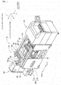
- Fig. 1 illustrates a component mounting apparatus 10.
- the component mounting apparatus 10 is an apparatus which performs mounting work of a component on a circuit substrate 12.
- the component mounting apparatus 10 includes an apparatus main body 20, a substrate conveyance and holding device 22, a component mounting device 24, imaging devices 26 and 28, a component supply device 30, and a bulk component supply device 32.
- An example of circuit substrate 12 includes a circuit board, a substrate having a three-dimensional structure, or the like, and an example of a circuit board includes a printed-wiring board, a printed-circuit board, or the like.
- the apparatus main body 20 is configured by a frame section 40 and a beam section 42 which is suspended over the frame section 40.
- the substrate conveyance and holding device 22 is installed in a center in a front-back direction of the frame section 40, and includes a conveyance device 50 and a clamping device 52.
- the conveyance device 50 is a device which conveys the circuit substrate 12
- the clamping device 52 is a device which holds the circuit substrate 12. Accordingly, the substrate conveyance and holding device 22 conveys the circuit substrate 12 and fixedly holds the circuit substrate 12 at a predetermined position.
- a conveyance direction of the circuit substrate 12 is referred to as an X-direction
- a horizontal direction perpendicular to the direction thereof is referred to as an Y-direction
- a vertical direction is referred to as a Z-direction.
- a width direction of the component mounting apparatus 10 is the X-direction
- the front-back direction thereof is the Y-direction.
- the component mounting device 24 is installed in the beam section 42, and includes two work heads 60 and 62 and a work head moving device 64.
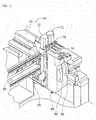
- a suction nozzle (see Fig. 2 ) 66 is provided on a lower end face of each of the work heads 60 and 62 to be attachable to and detachable from the lower end face thereof.
- the suction nozzle 66 communicates with a positive and negative pressure supply device (not illustrated) via an air flow path.
- the suction nozzle 66 sucks and holds the component by the negative pressure, and detaches the held component by the positive pressure.
- the work head moving device 64 includes an X-direction moving device 68, a Y-direction moving device 70, and a Z-direction moving device 72.
- each of the work heads 60 and 62 is mounted to be attachable to and detachable from sliders 74 and 76, and the Z-direction moving device 72 individually moves the sliders 74 and 76 in the up-down direction.
- the work heads 60 and 62 are individually moved in the up-down direction by the Z-direction moving device 72.
- the imaging device 26 is attached to the slider 74 in a state of facing downward, and is moved along with the work head 60 in the X-direction, the Y-direction, and the Z-direction. Accordingly, the imaging device 26 images the arbitrary position on the frame section 40. As illustrated in Fig. 1 , the imaging device 28 is installed between the substrate conveyance and holding device 22 on the frame section 40 and the component supply device 30 in a state of facing upward. Accordingly, the imaging device 28 images the component held by the suction nozzles 66 of the work heads 60 and 62.
- the component supply device 30 is installed at an end section of a side of the frame section 40 in the front-back direction.
- the component supply device 30 includes a tray-type component supply device 78 and a feeder-type component supply device (not illustrated).
- the tray-type component supply device 78 is a device for supplying a component which is in a state of being placed on a tray.
- the feeder-type component supply device is a device for supplying a component by a tape feeder (not illustrated).
- the bulk component supply device 32 is installed at an end section of the other side of the frame section 40 in the front-back direction.
- the bulk component supply device 32 is a device which aligns multiple components which are in a state of being scattered separately and supplies the components which are in an aligned state.
- the bulk component supply device is a device which aligns the multiple components which are in arbitrary postures in a predetermined posture and supplies the components which are in the predetermined posture.
- Examples of components supplied by the component supply device 30 and the bulk component supply device 32 include an electronic circuit component, a constituent component of a solar cell, a constituent component of the power module, or the like.
- the electronic circuit component includes a component having a lead, a component without a lead, or the like.
- the mounting work of the component is performed on the circuit substrate 12 held by the substrate conveyance and holding device 22 using the configuration described above. Specifically, the circuit substrate 12 is conveyed to a working position and is fixedly held by the clamping device 52 at the position. Next, the imaging device 26 moves above the circuit substrate 12 to image the circuit substrate 12. Accordingly, information on errors of the holding position of the circuit substrate 12 is obtained.
- the component supply device 30 or the bulk component supply device 32 supplies components to a predetermined supply position. Any of the work heads 60 and 62 moves above the supply position of the component and holds the component by using the negative pressure by the suction nozzle 66.
- the work heads 60 and 62 holding the component move above the imaging device 28, and the imaging device 28 images the component held by the suction nozzles 66. Accordingly, the information on the errors of the holding position of the component is obtained. Subsequently, the work heads 60 and 62 holding the component move above the circuit substrate 12, and correct the error of the holding position of the circuit substrate 12, the error of the holding position of the component, or the like.
- the component is mounted on the circuit substrate 12 by the suction nozzle 66 detaching the component using the positive pressure.
- the mounting work is performed by the suction nozzle 66 sucking and holding the component by negative pressure and detaching the component by positive pressure in the component mounting apparatus 10.
- the component mounted on the circuit substrate 12 includes a high adhesive member, for example, a member using rubber materials or the like and in a case where the high adhesive member is held by the suction nozzle 66, there is a case where the member is stuck to the suction nozzle 66 and thus is unlikely to be detached from the suction nozzle 66.
- a high adhesive member for example, a member using rubber materials or the like
- a member protruding from the suction surface of the suction nozzle 66 when the positive pressure air is supplied to the suction nozzle 66 is provided in the suction nozzle 66, and the component sucked and held to the suction nozzle 66 is forcibly detached from the suction nozzle by this member.
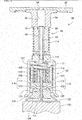
- a specific structure of the suction nozzle 66 will be described.
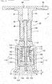
- the suction nozzle 66 includes an adapter 80 and a nozzle main body 82.
- the adapter 80 includes an adapter main body section 84, a flange section 86, and an expansion and contraction section 88.
- the adapter main body section 84 generally has a cylindrical shape and a through-hole 90 penetrating in the up-down direction is formed in the adapter main body section 84.
- the through-hole 90 has a stepped shape in which an inner diameter of a portion of an upper side thereof is larger than that of a portion of a lower side thereof, and a stepped surface 92 in a state of facing upward is formed in an inside section of the through-hole 90.
- the flange section 86 is fixed to the upper end surface of the adapter main body section 84 so as to extend in a radial direction of the adapter main body section 84, and a through-hole 94 communicating with the through-hole 90 of the adapter main body section 84 is formed on the flange section 86.
- the expansion and contraction section 88 generally has a cylindrical shape and a through-hole 96 penetrating in the up-down direction is formed in the expansion and contraction section 88.
- An outer diameter of the expansion and contraction section 88 is made slightly smaller than the inner diameter of the lower portion than the stepped surface 92 of the through-hole 90, and the expansion and contraction section 88 is inserted into the through-hole 90.
- an upper end section of the expansion and contraction section 88 extends to an upper portion than the stepped surface 92 of the through-hole 90 and a lower end section of the expansion and contraction section 88 extends from the lower end section of the adapter main body section 84. Accordingly, by the adapter main body section 84 and the expansion and contraction section 88 moving relative to each other, the extension amount of the expansion and contraction section 88 from the lower end section of the adapter main body section 84 changes, and the adapter 80 expands and contracts.
- a protruding section 98 protruding in the radial direction is formed on the upper end section of the expansion and contraction section 88. Accordingly, when the expansion and contraction section 88 moves downward, the protruding section 98 engages the stepped surface 92 of the through-hole 90 to prevent the expansion and contraction section 88 from coming off from the through-hole 90.
- the nozzle main body 82 includes a support member 100, a flow path forming member 102, a suction pad 104, a guide member 106, a rod pressing member 108, and a rod 110.
- the support member 100 generally has a cylindrical shape having a lid, and a through-hole 112 is formed in a center of a lid section thereof.
- the lower end section of the expansion and contraction section 88 of the adapter 80 is fixedly fitted in the through-hole 112.
- a coil spring 114 is installed in a compressed state between the support member 100 and the adapter main body section 84 of the adapter 80. Accordingly, the support member 100 is biased downward.
- a lower end section of the support member 100 is open in a trumpet shape. In other words, a peripheral wall of a lower end section of the support member 100 spreads outward, as going downward.
- the flow path forming member 102 generally has a cylindrical shape having a bottom, and an outer diameter of the flow path forming member 102 is slightly smaller than an inner diameter of the support member 100.
- the flow path forming member 102 is inserted into an inside section of the support member 100 from a lower side of the support member 100. Accordingly, the flow path forming member 102 slides in the up-down direction in the inside section of the support member 100.
- a coil spring 115 is installed in a compressed state between a bottom section of the flow path forming member 102 and the lid section of the support member 100. Accordingly, the flow path forming member 102 is biased downward.
- a stopper (not illustrated) is provided on an inner peripheral surface of the support member 100, and a downward movement of the flow path forming member 102 is restricted by the stopper.
- the flow path forming member 102 is illustrated in a state where the downward movement is restricted by the stopper.
- a peripheral wall section and a bottom section of the flow path forming member 102 are made thick, and the air flow path 116 is formed in the peripheral wall section and the bottom section thereof.
- multiple first flow paths (two first flow paths are illustrated in the figure) 118 are formed in the peripheral wall section of the flow path forming member 102 so as to extend in the up-down direction.
- An upper end of a first flow path 118 opens at an upper end of the flow path forming member 102, and a lower end of the first flow path 118 is not opened to the lower end of the flow path forming member 102, and the first flow path extends to the middle of the bottom section of the flow path forming member 102.
- multiple second flow paths 120 are formed on the bottom section of the flow path forming member 102 corresponding to the multiple first flow paths 118.
- the second flow path 120 is inclined and communicates with the lower end of the corresponding first flow path 118 at the upper end thereof.
- the lower end of the second flow path 120 opens to the center section of the bottom face of the flow path forming member 102.
- the lower ends of the multiple second flow paths 120 are open to the same portion of the bottom face of the flow path forming member 102 .
- a through-hole 121 penetrating in the up-down direction is formed in the center section of the bottom section of the flow path forming member 102.
- a through-hole 121 penetrating in the up-down direction is formed in the center section of the bottom section of the flow path forming member 102, and a lower end of the through-hole 121 is opened to the same position as the lower end of the multiple second flow paths 120.
- the lower end of the multiple second flow paths 120 and the lower end of the through-hole 121 are opened to one position of the bottom face of the flow path forming member 102.
- the suction pad 104 is formed of an elastically deformable material and generally has a short cylindrical column shape.
- the suction pad 104 is fixed to the lower end face of the flow path forming member 102, and a through-hole 122 penetrating in the up-down direction is formed in the suction pad 104.
- the upper end of the through-hole 122 communicates with the lower end of the second flow path 120 of the flow path forming member 102.
- a recessed section 124 is formed on the lower end face of the suction pad 104.
- the recessed section 124 is formed such that an outer edge section 126 of the lower end face of the suction pad 104 is a thin wall over an entire circumference thereof, and the outer edge section 126 spreads outward, as going downward.
- the outer edge section 126 is open in a trumpet shape. Although a portion of an upper side of the suction pad 104 is positioned in an inside section of the support member 100, the portion of the lower side of the suction pad 104, that is, the outer edge section 126 extends from the lower side of the support member 100. In addition, an outer diameter of the lower end of the outer edge section 126 is slightly smaller than the outer diameter of the lower end of the support member 100, and the outer edge section 126 and the lower end of the support member 100 are separated from each other.
- the guide member 106 generally has a cylindrical shape, and the outer diameter of the guide member 106 is smaller than the inner diameter of the flow path forming member 102.
- the guide member 106 is fixed in a state of being erected on the bottom section of the flow path forming member 102.
- the rod pressing member 108 generally has a cylindrical shape having a lid, and an outer diameter of the rod pressing member 108 is slightly smaller than the inner diameter of the guide member 106. A portion of a lower side of the rod pressing member 108 is inserted into the inside section of the guide member 106 from an upper side of the guide member 106 and the rod pressing member 108 is slid in the up-down direction at the inside section of the guide member 106 in the inserted section.
- a recessed section 128 is formed in an upper end surface of the rod pressing member 108 so as to face the through-hole 112 of the support member 100.
- the recessed section 128 is formed so as to extend in the radial direction of the rod pressing member 108 and reaches an outer peripheral surface of the rod pressing member 108. In other words, the recessed section 128 opens to the upper end surface and the outer peripheral surface of the rod pressing member 108.
- the rod 110 generally has a bar shape, the outer diameter thereof is slightly smaller than the inner diameter of the through-hole 121 of the flow path forming member 102 and is smaller than the inner diameter of the through-hole 122 of the suction pad 104.
- the rod 110 is accommodated in the inside sections of the guide member 106 and the rod pressing member 108 in the portion of the upper side thereof, is inserted into the through-hole 121 of the flow path forming member 102 at the center section thereof, and extends to the inside section of the through-hole 122 of the suction pad 104 in the portion of the lower side thereof. Accordingly, the rod 110 slides in the through-hole 121 of the flow path forming member 102, and the lower end section of the rod 110 moves in the up-down direction in the inside section of the through-hole 122 of the suction pad 104.
- a flange section 130 is formed on the upper end of the rod 110, and a coil spring 132 is installed in a compressed state between the flange section 130 and the bottom section of the flow path forming member 102. Accordingly, the rod 110 is biased upward.
- the upper end of the rod 110 is in contact with the lid section of the rod pressing member 108 and the rod pressing member 108 is also biased along with the rod 110 upward. Therefore, the lid section of the rod pressing member 108 is in contact with the lid section of the support member 100 and covers the through-hole 112.
- the recessed section 128 which opens to the upper end surface and the outer peripheral surface thereof is formed and thus even if the lid section of the rod pressing member 108 covers the through-hole 112, the through-hole 112 and the inside of the support member 100 communicate with each other via the recessed section 128.
- the lower end of the rod 110 is positioned a predetermined distance ⁇ above the lower end of the through-hole 122 of the suction pad 104.
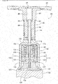
- the predetermined distance ⁇ is longer than a distance which the flow path forming member 102 is movable in the inside of the support member 100, that is, a distance between the flow path forming member 102 (flow path forming member 102 in Fig. 3 ) of which downward movement is restricted by the stopper and the flow path forming member 102 (flow path forming member 102 in Fig. 4 ) which is moved to the uppermost position against an elastic force of the coil spring 115.
- the suction nozzle 66 structured as described above, when the suction pad 104 is pressed against the component (see Fig. 4 ) 150 to be held, the outer edge section 126 of the suction pad 104 is in contact with the component 150 and elastically deforms. Accordingly, the inside section of the recessed section 124 of the suction pad 104 is sealed.
- negative pressure air is supplied to the through-holes 90, 94, and 96 of the adapter 80, that is, when air is sucked from the through-holes 90, 94, and 96 of the adapter 80, the air in the inside section of the support member 100 is sucked via the through-hole 112 of the support member 100 and the recessed section 128 of the rod pressing member 108.
- the flow path forming member 102 moves upward against the elastic force of the coil spring 115, and the suction pad 104 also moves upward along with the flow path forming member 102.
- the upper surface of the outer edge section 126 of the suction pad 104 is in contact with the lower end of the support member 100, and the outer edge section 126 is supported by the lower end of the support member 100 from the upper face side. Accordingly, because the outer edge section 126 elastically deformed by suction and holding of the component 150 is supported from the upper face side, the elastic deformation of the outer edge section 126 is suppressed and suction and holding of the component 150 is secured by the suction pad 104.
- the rod 110 relatively moves downward with respect to the flow path forming member 102 and the suction pad 104 according to upward movement of the flow path forming member 102 and the suction pad 104, the lower end of the rod 110 is positioned above the lower end of the opening of the through-hole 122 of the suction pad 104 since the predetermined distance ⁇ described above is longer than the movement amount of the flow path forming member 102. Therefore, regardless of the relative downward movement of the rod 110, the suction nozzle 66 sucks and holds the component 150 appropriately.
- the flow path forming member 102 moves downward and the suction pads 104 also move downward along with the flow path forming member 102 in the inside section of the support member 100 by the elastic force of the coil spring 115.
- the rod pressing member 108 moves downward, and the rod 110 moves downward against the elastic force of the coil spring 132 along with the rod pressing member 108, by the air blown from the through-hole 112 of the support member 100. Accordingly, the lower end of the rod 110 further moves downward than the lower end of the outer edge section 126 of the suction pad 104, and is in contact with the component 150.
- the rod 110 descends, and the lower end of the rod 110 is in contact with the component 150. Accordingly, even when the component 150 is in close contact with the outer edge section 126 of the suction pad 104 and the component 150 is unlikely to be detached from the suction pad 104, the component 150 can be securely detached.
- the suction nozzle 66 is an example of a suction nozzle.
- the through-hole 90 is an example of an air flow path.
- the through-hole 94 is an example of an air flow path.
- the through-hole 96 is an example of an air flow path.
- the support member 100 is an example of a support member.
- the suction pad 104 is an example of a suction pad.
- the rod 110 is an example of a movable member.
- the through-hole 112 is an example of an air flow path.
- the air flow path 116 is an example of an air flow path.
- the through-hole 122 is an example of an air flow path.
- the recessed section 128 is an example of an air flow path.
- the present invention is limited by the appended claims, and can be implemented in various aspects in which various modifications and improvements are made based on knowledge of those skilled in the art.
- the lower end of the support member 100 and the outer edge section 126 of the suction pad 104 are normally separated from each other, and when negative pressure air is supplied to the suction nozzle 66, the outer edge section 126 of the suction pad 104 is supported by the support member 100, but the outer edge section 126 of the suction pad 104 may be always supported by the support member 100, regardless of the supply of negative pressure air to the suction nozzle 66.
- suction nozzle 90: through-hole (air flow path), 94: through-hole (air flow path), 96: through-hole (air flow path), 100: support member, 104: suction pad, 110: rod (movable member), 112 : through-hole (air flow path), 116: air flow path, 122: through-hole (air flow path), 128: recessed section (air flow path)
Landscapes
- Engineering & Computer Science (AREA)
- Robotics (AREA)
- Mechanical Engineering (AREA)
- Manufacturing & Machinery (AREA)
- Microelectronics & Electronic Packaging (AREA)
- Chemical & Material Sciences (AREA)
- Dispersion Chemistry (AREA)
- Supply And Installment Of Electrical Components (AREA)
- Manipulator (AREA)
Applications Claiming Priority (1)
| Application Number | Priority Date | Filing Date | Title |
|---|---|---|---|
| PCT/JP2014/077161 WO2016056115A1 (ja) | 2014-10-10 | 2014-10-10 | 吸着ノズル |
Publications (3)
| Publication Number | Publication Date |
|---|---|
| EP3205458A1 EP3205458A1 (en) | 2017-08-16 |
| EP3205458A4 EP3205458A4 (en) | 2017-10-11 |
| EP3205458B1 true EP3205458B1 (en) | 2020-12-02 |
Family
ID=55652771
Family Applications (1)
| Application Number | Title | Priority Date | Filing Date |
|---|---|---|---|
| EP14903588.3A Active EP3205458B1 (en) | 2014-10-10 | 2014-10-10 | Adsorption nozzle |
Country Status (5)
| Country | Link |
|---|---|
| US (1) | US10040205B2 (ja) |
| EP (1) | EP3205458B1 (ja) |
| JP (1) | JP6472812B2 (ja) |
| CN (1) | CN106794582B (ja) |
| WO (1) | WO2016056115A1 (ja) |
Families Citing this family (9)
| Publication number | Priority date | Publication date | Assignee | Title |
|---|---|---|---|---|
| JP6325589B2 (ja) * | 2016-03-07 | 2018-05-16 | 株式会社日本ピスコ | 吸着用パッド |
| CN106826624B (zh) * | 2017-02-28 | 2018-10-12 | 京东方科技集团股份有限公司 | 真空吸附单元和真空吸附载台 |
| JP6609293B2 (ja) | 2017-08-30 | 2019-11-20 | 平田機工株式会社 | 保持ノズル、保持ヘッド及び移載装置 |
| NL2019526B1 (nl) * | 2017-09-11 | 2019-03-19 | Harrisson B V | Vacuümkop voor het vastpakken van een voorwerp, in het bijzonder een LED |
| SE543130C2 (en) * | 2018-04-22 | 2020-10-13 | Zenrobotics Oy | A waste sorting robot gripper |
| DE102018110741A1 (de) * | 2018-05-04 | 2019-11-07 | J. Schmalz Gmbh | Unterdruckhandhabungsvorrichtung |
| SE544741C2 (en) | 2018-05-11 | 2022-11-01 | Genie Ind Bv | Waste Sorting Gantry Robot and associated method |
| JP7075498B2 (ja) * | 2018-10-02 | 2022-05-25 | 株式会社Fuji | 作業機 |
| WO2021059318A1 (ja) * | 2019-09-24 | 2021-04-01 | 株式会社Fuji | 乾燥装置、および乾燥方法 |
Family Cites Families (33)
| Publication number | Priority date | Publication date | Assignee | Title |
|---|---|---|---|---|
| JPS5223744Y2 (ja) | 1971-07-30 | 1977-05-30 | ||
| JPS5898191U (ja) | 1981-12-24 | 1983-07-04 | 日本ビクター株式会社 | 強制離脱型真空チヤツク |
| DE3325207A1 (de) * | 1983-07-13 | 1985-01-31 | Peter-Uhren Gmbh, 7210 Rottweil | Sauggreifer mit selbststeuernder saugoeffnung |
| DE3562478D1 (en) * | 1984-11-13 | 1988-06-09 | Mania Gmbh | Mechanically activated deflector for lifting and holding objects |
| JPH042786Y2 (ja) * | 1986-11-08 | 1992-01-30 | ||
| DE3714388A1 (de) * | 1987-04-30 | 1988-11-10 | Festo Kg | Saugnapf |
| US4850780A (en) * | 1987-09-28 | 1989-07-25 | Kulicke And Soffa Industries Inc. | Pre-peel die ejector apparatus |
| US5183670A (en) | 1991-04-30 | 1993-02-02 | United Technologies Corporation | Bi-functional transfer foot |
| JPH0523987A (ja) * | 1991-07-18 | 1993-02-02 | Rohm Co Ltd | 電子部品吸着コレツト装置 |
| JPH0526284U (ja) * | 1991-09-20 | 1993-04-06 | 関西日本電気株式会社 | 吸着装置 |
| JPH06349868A (ja) * | 1993-06-11 | 1994-12-22 | Fuji Electric Co Ltd | 半導体素子吸着装置 |
| JPH1145930A (ja) * | 1997-07-24 | 1999-02-16 | Toshiba Electron Eng Corp | 吸着ヘッド |
| JP3797577B2 (ja) * | 1997-10-20 | 2006-07-19 | Smc株式会社 | 吸着装置 |
| JP2001025988A (ja) | 1999-07-14 | 2001-01-30 | Nec Machinery Corp | 部材の離脱方法 |
| JP4291497B2 (ja) * | 2000-05-11 | 2009-07-08 | 株式会社妙徳 | 吸着パッド |
| KR100371228B1 (ko) | 2000-12-19 | 2003-02-06 | 미래산업 주식회사 | 표면실장기의 노즐장치 |
| JP2002313883A (ja) | 2001-04-18 | 2002-10-25 | Anritsu Corp | 電子デバイス搬送装置 |
| JP4092487B2 (ja) * | 2003-04-03 | 2008-05-28 | 日産自動車株式会社 | 吸着装置 |
| KR20050122909A (ko) | 2004-06-25 | 2005-12-29 | 한미반도체 주식회사 | 반도체 패키지 픽커 |
| US7441734B2 (en) * | 2006-04-04 | 2008-10-28 | Haicom Electronics Corp. | Vehicle-used suction disk retainer |
| KR100791004B1 (ko) * | 2006-12-01 | 2008-01-04 | 삼성전자주식회사 | 진공 흡착형 피커 및 피킹 방법 |
| US20080179905A1 (en) * | 2007-01-25 | 2008-07-31 | Mommy's Helper, Inc. | Handheld gripping device |
| JP2010099733A (ja) | 2008-10-27 | 2010-05-06 | Disco Abrasive Syst Ltd | レーザ加工装置 |
| CN102712018B (zh) * | 2009-11-12 | 2015-10-07 | 过滤器安全有限公司 | 过滤器近端喷嘴 |
| CN201714423U (zh) * | 2010-07-21 | 2011-01-19 | 周泉清 | 拉力吸嘴 |
| JP2012055977A (ja) * | 2010-09-06 | 2012-03-22 | Fujitsu Ltd | ワーク支持装置及びワーク支持方法 |
| CN102450125A (zh) * | 2010-10-22 | 2012-05-16 | 崔敏娟 | 自清洁吸嘴 |
| US9108319B2 (en) * | 2011-02-01 | 2015-08-18 | Delaware Capital Formation, Inc. | Electric suction cup |
| WO2013034635A1 (de) * | 2011-09-07 | 2013-03-14 | J. Schmalz Gmbh | Greif- oder spannvorrichtung sowie verfahren zur handhabung von gegenständen |
| JP5913731B2 (ja) * | 2013-02-28 | 2016-04-27 | ヤマハ発動機株式会社 | 吸着ノズルおよび表面実装機 |
| CN203697017U (zh) * | 2013-12-03 | 2014-07-09 | 安徽精一机械设备有限公司 | 一种玻璃上片用机械手吸盘 |
| CN203702825U (zh) * | 2014-01-16 | 2014-07-09 | 奇塑科技(江阴)有限公司 | 一种吸盘 |
| JP5610658B1 (ja) | 2014-03-31 | 2014-10-22 | アキム株式会社 | ノズル構造及び吸着方法 |
-
2014
- 2014-10-10 US US15/511,724 patent/US10040205B2/en active Active
- 2014-10-10 CN CN201480082476.2A patent/CN106794582B/zh active Active
- 2014-10-10 EP EP14903588.3A patent/EP3205458B1/en active Active
- 2014-10-10 JP JP2016552779A patent/JP6472812B2/ja active Active
- 2014-10-10 WO PCT/JP2014/077161 patent/WO2016056115A1/ja active Application Filing
Non-Patent Citations (1)
| Title |
|---|
| None * |
Also Published As
| Publication number | Publication date |
|---|---|
| CN106794582B (zh) | 2020-01-31 |
| EP3205458A1 (en) | 2017-08-16 |
| CN106794582A (zh) | 2017-05-31 |
| WO2016056115A1 (ja) | 2016-04-14 |
| US10040205B2 (en) | 2018-08-07 |
| JP6472812B2 (ja) | 2019-02-20 |
| EP3205458A4 (en) | 2017-10-11 |
| US20170291308A1 (en) | 2017-10-12 |
| JPWO2016056115A1 (ja) | 2017-07-20 |
Similar Documents
| Publication | Publication Date | Title |
|---|---|---|
| EP3205458B1 (en) | Adsorption nozzle | |
| CN104347435B (zh) | 吸附筒夹和芯片接合器 | |
| US10477748B2 (en) | Component mounting device and component mounting method | |
| CN107180772B (zh) | 芯片贴装装置以及半导体器件的制造方法 | |
| KR101896800B1 (ko) | 반도체 패키지 픽업 장치 | |
| KR102350553B1 (ko) | 반도체 칩을 픽업하기 위한 피커 | |
| CN108400096B (zh) | 半导体制造装置及半导体器件的制造方法 | |
| CN103523553B (zh) | 取料机构 | |
| KR101595832B1 (ko) | 백업 핀 및 기판 처리 장치 | |
| KR20200033177A (ko) | 다이 본딩 장치 및 반도체 장치의 제조 방법 | |
| JP6027794B2 (ja) | 搬送治具 | |
| KR20190020641A (ko) | 실장 방법, 실장용 헤드 및 실장 장치 | |
| CN113099713B (zh) | 元件保持装置、装配头、装配机及装配元件载体的方法 | |
| KR101915204B1 (ko) | 폭 조정이 가능한 트레이 홀더 조립체 | |
| US11224977B2 (en) | Chuck for holding mounting component, and component mounting machine | |
| CN107529332B (zh) | 用于部件贴装机的吸嘴组件 | |
| US10349569B2 (en) | Component mounting device and component mounting method | |
| CN114084456A (zh) | 自动剥离装置及贴标签设备 | |
| KR101599812B1 (ko) | 반도체패키지의 흡착고정수단 | |
| KR101411109B1 (ko) | 픽업 유닛의 수평 상태 검사 방법 | |
| CN108128510B (zh) | 一种贴装方法 | |
| KR102050741B1 (ko) | 반도체 제조 장치 및 반도체 장치의 제조 방법 | |
| KR20170127325A (ko) | 반도체소자 캐리어 및 이를 포함하는 소자핸들러 | |
| WO2023209953A1 (ja) | 部品突上げ装置及び部品実装装置 | |
| KR20160019135A (ko) | 콜릿 공급 장치 |
Legal Events
| Date | Code | Title | Description |
|---|---|---|---|
| STAA | Information on the status of an ep patent application or granted ep patent |
Free format text: STATUS: THE INTERNATIONAL PUBLICATION HAS BEEN MADE |
|
| PUAI | Public reference made under article 153(3) epc to a published international application that has entered the european phase |
Free format text: ORIGINAL CODE: 0009012 |
|
| STAA | Information on the status of an ep patent application or granted ep patent |
Free format text: STATUS: REQUEST FOR EXAMINATION WAS MADE |
|
| 17P | Request for examination filed |
Effective date: 20170329 |
|
| AK | Designated contracting states |
Kind code of ref document: A1 Designated state(s): AL AT BE BG CH CY CZ DE DK EE ES FI FR GB GR HR HU IE IS IT LI LT LU LV MC MK MT NL NO PL PT RO RS SE SI SK SM TR |
|
| AX | Request for extension of the european patent |
Extension state: BA ME |
|
| A4 | Supplementary search report drawn up and despatched |
Effective date: 20170913 |
|
| RIC1 | Information provided on ipc code assigned before grant |
Ipc: H05K 13/04 20060101ALI20170907BHEP Ipc: B25J 15/06 20060101AFI20170907BHEP |
|
| DAX | Request for extension of the european patent (deleted) | ||
| RAP1 | Party data changed (applicant data changed or rights of an application transferred) |
Owner name: FUJI CORPORATION |
|
| RIN1 | Information on inventor provided before grant (corrected) |
Inventor name: YAMAMURO, JUNICHI |
|
| STAA | Information on the status of an ep patent application or granted ep patent |
Free format text: STATUS: EXAMINATION IS IN PROGRESS |
|
| 17Q | First examination report despatched |
Effective date: 20191007 |
|
| GRAP | Despatch of communication of intention to grant a patent |
Free format text: ORIGINAL CODE: EPIDOSNIGR1 |
|
| STAA | Information on the status of an ep patent application or granted ep patent |
Free format text: STATUS: GRANT OF PATENT IS INTENDED |
|
| INTG | Intention to grant announced |
Effective date: 20200723 |
|
| GRAS | Grant fee paid |
Free format text: ORIGINAL CODE: EPIDOSNIGR3 |
|
| GRAA | (expected) grant |
Free format text: ORIGINAL CODE: 0009210 |
|
| STAA | Information on the status of an ep patent application or granted ep patent |
Free format text: STATUS: THE PATENT HAS BEEN GRANTED |
|
| AK | Designated contracting states |
Kind code of ref document: B1 Designated state(s): AL AT BE BG CH CY CZ DE DK EE ES FI FR GB GR HR HU IE IS IT LI LT LU LV MC MK MT NL NO PL PT RO RS SE SI SK SM TR |
|
| REG | Reference to a national code |
Ref country code: GB Ref legal event code: FG4D |
|
| REG | Reference to a national code |
Ref country code: AT Ref legal event code: REF Ref document number: 1340396 Country of ref document: AT Kind code of ref document: T Effective date: 20201215 Ref country code: CH Ref legal event code: EP |
|
| REG | Reference to a national code |
Ref country code: DE Ref legal event code: R096 Ref document number: 602014073091 Country of ref document: DE |
|
| REG | Reference to a national code |
Ref country code: IE Ref legal event code: FG4D |
|
| PG25 | Lapsed in a contracting state [announced via postgrant information from national office to epo] |
Ref country code: GR Free format text: LAPSE BECAUSE OF FAILURE TO SUBMIT A TRANSLATION OF THE DESCRIPTION OR TO PAY THE FEE WITHIN THE PRESCRIBED TIME-LIMIT Effective date: 20210303 Ref country code: RS Free format text: LAPSE BECAUSE OF FAILURE TO SUBMIT A TRANSLATION OF THE DESCRIPTION OR TO PAY THE FEE WITHIN THE PRESCRIBED TIME-LIMIT Effective date: 20201202 Ref country code: FI Free format text: LAPSE BECAUSE OF FAILURE TO SUBMIT A TRANSLATION OF THE DESCRIPTION OR TO PAY THE FEE WITHIN THE PRESCRIBED TIME-LIMIT Effective date: 20201202 Ref country code: NO Free format text: LAPSE BECAUSE OF FAILURE TO SUBMIT A TRANSLATION OF THE DESCRIPTION OR TO PAY THE FEE WITHIN THE PRESCRIBED TIME-LIMIT Effective date: 20210302 |
|
| REG | Reference to a national code |
Ref country code: NL Ref legal event code: MP Effective date: 20201202 |
|
| REG | Reference to a national code |
Ref country code: AT Ref legal event code: MK05 Ref document number: 1340396 Country of ref document: AT Kind code of ref document: T Effective date: 20201202 |
|
| PG25 | Lapsed in a contracting state [announced via postgrant information from national office to epo] |
Ref country code: SE Free format text: LAPSE BECAUSE OF FAILURE TO SUBMIT A TRANSLATION OF THE DESCRIPTION OR TO PAY THE FEE WITHIN THE PRESCRIBED TIME-LIMIT Effective date: 20201202 Ref country code: LV Free format text: LAPSE BECAUSE OF FAILURE TO SUBMIT A TRANSLATION OF THE DESCRIPTION OR TO PAY THE FEE WITHIN THE PRESCRIBED TIME-LIMIT Effective date: 20201202 Ref country code: PL Free format text: LAPSE BECAUSE OF FAILURE TO SUBMIT A TRANSLATION OF THE DESCRIPTION OR TO PAY THE FEE WITHIN THE PRESCRIBED TIME-LIMIT Effective date: 20201202 Ref country code: BG Free format text: LAPSE BECAUSE OF FAILURE TO SUBMIT A TRANSLATION OF THE DESCRIPTION OR TO PAY THE FEE WITHIN THE PRESCRIBED TIME-LIMIT Effective date: 20210302 |
|
| PG25 | Lapsed in a contracting state [announced via postgrant information from national office to epo] |
Ref country code: HR Free format text: LAPSE BECAUSE OF FAILURE TO SUBMIT A TRANSLATION OF THE DESCRIPTION OR TO PAY THE FEE WITHIN THE PRESCRIBED TIME-LIMIT Effective date: 20201202 Ref country code: NL Free format text: LAPSE BECAUSE OF FAILURE TO SUBMIT A TRANSLATION OF THE DESCRIPTION OR TO PAY THE FEE WITHIN THE PRESCRIBED TIME-LIMIT Effective date: 20201202 |
|
| REG | Reference to a national code |
Ref country code: LT Ref legal event code: MG9D |
|
| PG25 | Lapsed in a contracting state [announced via postgrant information from national office to epo] |
Ref country code: PT Free format text: LAPSE BECAUSE OF FAILURE TO SUBMIT A TRANSLATION OF THE DESCRIPTION OR TO PAY THE FEE WITHIN THE PRESCRIBED TIME-LIMIT Effective date: 20210405 Ref country code: SK Free format text: LAPSE BECAUSE OF FAILURE TO SUBMIT A TRANSLATION OF THE DESCRIPTION OR TO PAY THE FEE WITHIN THE PRESCRIBED TIME-LIMIT Effective date: 20201202 Ref country code: RO Free format text: LAPSE BECAUSE OF FAILURE TO SUBMIT A TRANSLATION OF THE DESCRIPTION OR TO PAY THE FEE WITHIN THE PRESCRIBED TIME-LIMIT Effective date: 20201202 Ref country code: LT Free format text: LAPSE BECAUSE OF FAILURE TO SUBMIT A TRANSLATION OF THE DESCRIPTION OR TO PAY THE FEE WITHIN THE PRESCRIBED TIME-LIMIT Effective date: 20201202 Ref country code: SM Free format text: LAPSE BECAUSE OF FAILURE TO SUBMIT A TRANSLATION OF THE DESCRIPTION OR TO PAY THE FEE WITHIN THE PRESCRIBED TIME-LIMIT Effective date: 20201202 Ref country code: CZ Free format text: LAPSE BECAUSE OF FAILURE TO SUBMIT A TRANSLATION OF THE DESCRIPTION OR TO PAY THE FEE WITHIN THE PRESCRIBED TIME-LIMIT Effective date: 20201202 Ref country code: EE Free format text: LAPSE BECAUSE OF FAILURE TO SUBMIT A TRANSLATION OF THE DESCRIPTION OR TO PAY THE FEE WITHIN THE PRESCRIBED TIME-LIMIT Effective date: 20201202 |
|
| PG25 | Lapsed in a contracting state [announced via postgrant information from national office to epo] |
Ref country code: AT Free format text: LAPSE BECAUSE OF FAILURE TO SUBMIT A TRANSLATION OF THE DESCRIPTION OR TO PAY THE FEE WITHIN THE PRESCRIBED TIME-LIMIT Effective date: 20201202 |
|
| REG | Reference to a national code |
Ref country code: DE Ref legal event code: R097 Ref document number: 602014073091 Country of ref document: DE |
|
| PG25 | Lapsed in a contracting state [announced via postgrant information from national office to epo] |
Ref country code: IS Free format text: LAPSE BECAUSE OF FAILURE TO SUBMIT A TRANSLATION OF THE DESCRIPTION OR TO PAY THE FEE WITHIN THE PRESCRIBED TIME-LIMIT Effective date: 20210402 |
|
| PLBE | No opposition filed within time limit |
Free format text: ORIGINAL CODE: 0009261 |
|
| STAA | Information on the status of an ep patent application or granted ep patent |
Free format text: STATUS: NO OPPOSITION FILED WITHIN TIME LIMIT |
|
| PG25 | Lapsed in a contracting state [announced via postgrant information from national office to epo] |
Ref country code: AL Free format text: LAPSE BECAUSE OF FAILURE TO SUBMIT A TRANSLATION OF THE DESCRIPTION OR TO PAY THE FEE WITHIN THE PRESCRIBED TIME-LIMIT Effective date: 20201202 |
|
| 26N | No opposition filed |
Effective date: 20210903 |
|
| PG25 | Lapsed in a contracting state [announced via postgrant information from national office to epo] |
Ref country code: SI Free format text: LAPSE BECAUSE OF FAILURE TO SUBMIT A TRANSLATION OF THE DESCRIPTION OR TO PAY THE FEE WITHIN THE PRESCRIBED TIME-LIMIT Effective date: 20201202 Ref country code: DK Free format text: LAPSE BECAUSE OF FAILURE TO SUBMIT A TRANSLATION OF THE DESCRIPTION OR TO PAY THE FEE WITHIN THE PRESCRIBED TIME-LIMIT Effective date: 20201202 |
|
| PG25 | Lapsed in a contracting state [announced via postgrant information from national office to epo] |
Ref country code: ES Free format text: LAPSE BECAUSE OF FAILURE TO SUBMIT A TRANSLATION OF THE DESCRIPTION OR TO PAY THE FEE WITHIN THE PRESCRIBED TIME-LIMIT Effective date: 20201202 |
|
| REG | Reference to a national code |
Ref country code: CH Ref legal event code: PL |
|
| PG25 | Lapsed in a contracting state [announced via postgrant information from national office to epo] |
Ref country code: IS Free format text: LAPSE BECAUSE OF FAILURE TO SUBMIT A TRANSLATION OF THE DESCRIPTION OR TO PAY THE FEE WITHIN THE PRESCRIBED TIME-LIMIT Effective date: 20210402 |
|
| REG | Reference to a national code |
Ref country code: BE Ref legal event code: MM Effective date: 20211031 |
|
| GBPC | Gb: european patent ceased through non-payment of renewal fee |
Effective date: 20211010 |
|
| PG25 | Lapsed in a contracting state [announced via postgrant information from national office to epo] |
Ref country code: MC Free format text: LAPSE BECAUSE OF FAILURE TO SUBMIT A TRANSLATION OF THE DESCRIPTION OR TO PAY THE FEE WITHIN THE PRESCRIBED TIME-LIMIT Effective date: 20201202 |
|
| PG25 | Lapsed in a contracting state [announced via postgrant information from national office to epo] |
Ref country code: LU Free format text: LAPSE BECAUSE OF NON-PAYMENT OF DUE FEES Effective date: 20211010 Ref country code: GB Free format text: LAPSE BECAUSE OF NON-PAYMENT OF DUE FEES Effective date: 20211010 Ref country code: BE Free format text: LAPSE BECAUSE OF NON-PAYMENT OF DUE FEES Effective date: 20211031 |
|
| PG25 | Lapsed in a contracting state [announced via postgrant information from national office to epo] |
Ref country code: LI Free format text: LAPSE BECAUSE OF NON-PAYMENT OF DUE FEES Effective date: 20211031 Ref country code: CH Free format text: LAPSE BECAUSE OF NON-PAYMENT OF DUE FEES Effective date: 20211031 |
|
| PG25 | Lapsed in a contracting state [announced via postgrant information from national office to epo] |
Ref country code: FR Free format text: LAPSE BECAUSE OF NON-PAYMENT OF DUE FEES Effective date: 20211031 |
|
| PG25 | Lapsed in a contracting state [announced via postgrant information from national office to epo] |
Ref country code: IE Free format text: LAPSE BECAUSE OF NON-PAYMENT OF DUE FEES Effective date: 20211010 |
|
| PG25 | Lapsed in a contracting state [announced via postgrant information from national office to epo] |
Ref country code: HU Free format text: LAPSE BECAUSE OF FAILURE TO SUBMIT A TRANSLATION OF THE DESCRIPTION OR TO PAY THE FEE WITHIN THE PRESCRIBED TIME-LIMIT; INVALID AB INITIO Effective date: 20141010 |
|
| P01 | Opt-out of the competence of the unified patent court (upc) registered |
Effective date: 20230328 |
|
| PG25 | Lapsed in a contracting state [announced via postgrant information from national office to epo] |
Ref country code: CY Free format text: LAPSE BECAUSE OF FAILURE TO SUBMIT A TRANSLATION OF THE DESCRIPTION OR TO PAY THE FEE WITHIN THE PRESCRIBED TIME-LIMIT Effective date: 20201202 |
|
| PGFP | Annual fee paid to national office [announced via postgrant information from national office to epo] |
Ref country code: IT Payment date: 20230913 Year of fee payment: 10 |
|
| PGFP | Annual fee paid to national office [announced via postgrant information from national office to epo] |
Ref country code: DE Payment date: 20230830 Year of fee payment: 10 |
|
| PG25 | Lapsed in a contracting state [announced via postgrant information from national office to epo] |
Ref country code: MK Free format text: LAPSE BECAUSE OF FAILURE TO SUBMIT A TRANSLATION OF THE DESCRIPTION OR TO PAY THE FEE WITHIN THE PRESCRIBED TIME-LIMIT Effective date: 20201202 |