EP3159974B2 - Elektrische anschlussklemme - Google Patents
Elektrische anschlussklemme Download PDFInfo
- Publication number
- EP3159974B2 EP3159974B2 EP16197946.3A EP16197946A EP3159974B2 EP 3159974 B2 EP3159974 B2 EP 3159974B2 EP 16197946 A EP16197946 A EP 16197946A EP 3159974 B2 EP3159974 B2 EP 3159974B2
- Authority
- EP
- European Patent Office
- Prior art keywords
- electrical connection
- connection terminal
- housing
- pusher
- conductor
- Prior art date
- Legal status (The legal status is an assumption and is not a legal conclusion. Google has not performed a legal analysis and makes no representation as to the accuracy of the status listed.)
- Active
Links
Images

Classifications
-
- H—ELECTRICITY
- H01—ELECTRIC ELEMENTS
- H01R—ELECTRICALLY-CONDUCTIVE CONNECTIONS; STRUCTURAL ASSOCIATIONS OF A PLURALITY OF MUTUALLY-INSULATED ELECTRICAL CONNECTING ELEMENTS; COUPLING DEVICES; CURRENT COLLECTORS
- H01R13/00—Details of coupling devices of the kinds covered by groups H01R12/70 or H01R24/00 - H01R33/00
- H01R13/46—Bases; Cases
- H01R13/50—Bases; Cases formed as an integral body
-
- H—ELECTRICITY
- H01—ELECTRIC ELEMENTS
- H01R—ELECTRICALLY-CONDUCTIVE CONNECTIONS; STRUCTURAL ASSOCIATIONS OF A PLURALITY OF MUTUALLY-INSULATED ELECTRICAL CONNECTING ELEMENTS; COUPLING DEVICES; CURRENT COLLECTORS
- H01R13/00—Details of coupling devices of the kinds covered by groups H01R12/70 or H01R24/00 - H01R33/00
- H01R13/62—Means for facilitating engagement or disengagement of coupling parts or for holding them in engagement
- H01R13/629—Additional means for facilitating engagement or disengagement of coupling parts, e.g. aligning or guiding means, levers, gas pressure electrical locking indicators, manufacturing tolerances
-
- H—ELECTRICITY
- H01—ELECTRIC ELEMENTS
- H01R—ELECTRICALLY-CONDUCTIVE CONNECTIONS; STRUCTURAL ASSOCIATIONS OF A PLURALITY OF MUTUALLY-INSULATED ELECTRICAL CONNECTING ELEMENTS; COUPLING DEVICES; CURRENT COLLECTORS
- H01R12/00—Structural associations of a plurality of mutually-insulated electrical connecting elements, specially adapted for printed circuits, e.g. printed circuit boards [PCB], flat or ribbon cables, or like generally planar structures, e.g. terminal strips, terminal blocks; Coupling devices specially adapted for printed circuits, flat or ribbon cables, or like generally planar structures; Terminals specially adapted for contact with, or insertion into, printed circuits, flat or ribbon cables, or like generally planar structures
- H01R12/50—Fixed connections
- H01R12/51—Fixed connections for rigid printed circuits or like structures
- H01R12/515—Terminal blocks providing connections to wires or cables
-
- H—ELECTRICITY
- H01—ELECTRIC ELEMENTS
- H01R—ELECTRICALLY-CONDUCTIVE CONNECTIONS; STRUCTURAL ASSOCIATIONS OF A PLURALITY OF MUTUALLY-INSULATED ELECTRICAL CONNECTING ELEMENTS; COUPLING DEVICES; CURRENT COLLECTORS
- H01R13/00—Details of coupling devices of the kinds covered by groups H01R12/70 or H01R24/00 - H01R33/00
- H01R13/02—Contact members
- H01R13/193—Means for increasing contact pressure at the end of engagement of coupling part, e.g. zero insertion force or no friction
-
- H—ELECTRICITY
- H01—ELECTRIC ELEMENTS
- H01R—ELECTRICALLY-CONDUCTIVE CONNECTIONS; STRUCTURAL ASSOCIATIONS OF A PLURALITY OF MUTUALLY-INSULATED ELECTRICAL CONNECTING ELEMENTS; COUPLING DEVICES; CURRENT COLLECTORS
- H01R13/00—Details of coupling devices of the kinds covered by groups H01R12/70 or H01R24/00 - H01R33/00
- H01R13/46—Bases; Cases
-
- H—ELECTRICITY
- H01—ELECTRIC ELEMENTS
- H01R—ELECTRICALLY-CONDUCTIVE CONNECTIONS; STRUCTURAL ASSOCIATIONS OF A PLURALITY OF MUTUALLY-INSULATED ELECTRICAL CONNECTING ELEMENTS; COUPLING DEVICES; CURRENT COLLECTORS
- H01R4/00—Electrically-conductive connections between two or more conductive members in direct contact, i.e. touching one another; Means for effecting or maintaining such contact; Electrically-conductive connections having two or more spaced connecting locations for conductors and using contact members penetrating insulation
- H01R4/28—Clamped connections, spring connections
- H01R4/48—Clamped connections, spring connections utilising a spring, clip, or other resilient member
- H01R4/4809—Clamped connections, spring connections utilising a spring, clip, or other resilient member using a leaf spring to bias the conductor toward the busbar
- H01R4/4828—Spring-activating arrangements mounted on or integrally formed with the spring housing
- H01R4/483—Pivoting arrangements, e.g. lever pushing on the spring
-
- H—ELECTRICITY
- H01—ELECTRIC ELEMENTS
- H01R—ELECTRICALLY-CONDUCTIVE CONNECTIONS; STRUCTURAL ASSOCIATIONS OF A PLURALITY OF MUTUALLY-INSULATED ELECTRICAL CONNECTING ELEMENTS; COUPLING DEVICES; CURRENT COLLECTORS
- H01R9/00—Structural associations of a plurality of mutually-insulated electrical connecting elements, e.g. terminal strips or terminal blocks; Terminals or binding posts mounted upon a base or in a case; Bases therefor
- H01R9/22—Bases, e.g. strip, block, panel
- H01R9/24—Terminal blocks
-
- H—ELECTRICITY
- H01—ELECTRIC ELEMENTS
- H01R—ELECTRICALLY-CONDUCTIVE CONNECTIONS; STRUCTURAL ASSOCIATIONS OF A PLURALITY OF MUTUALLY-INSULATED ELECTRICAL CONNECTING ELEMENTS; COUPLING DEVICES; CURRENT COLLECTORS
- H01R12/00—Structural associations of a plurality of mutually-insulated electrical connecting elements, specially adapted for printed circuits, e.g. printed circuit boards [PCB], flat or ribbon cables, or like generally planar structures, e.g. terminal strips, terminal blocks; Coupling devices specially adapted for printed circuits, flat or ribbon cables, or like generally planar structures; Terminals specially adapted for contact with, or insertion into, printed circuits, flat or ribbon cables, or like generally planar structures
- H01R12/50—Fixed connections
- H01R12/51—Fixed connections for rigid printed circuits or like structures
- H01R12/55—Fixed connections for rigid printed circuits or like structures characterised by the terminals
- H01R12/57—Fixed connections for rigid printed circuits or like structures characterised by the terminals surface mounting terminals
-
- H—ELECTRICITY
- H01—ELECTRIC ELEMENTS
- H01R—ELECTRICALLY-CONDUCTIVE CONNECTIONS; STRUCTURAL ASSOCIATIONS OF A PLURALITY OF MUTUALLY-INSULATED ELECTRICAL CONNECTING ELEMENTS; COUPLING DEVICES; CURRENT COLLECTORS
- H01R4/00—Electrically-conductive connections between two or more conductive members in direct contact, i.e. touching one another; Means for effecting or maintaining such contact; Electrically-conductive connections having two or more spaced connecting locations for conductors and using contact members penetrating insulation
- H01R4/28—Clamped connections, spring connections
- H01R4/48—Clamped connections, spring connections utilising a spring, clip, or other resilient member
- H01R4/4809—Clamped connections, spring connections utilising a spring, clip, or other resilient member using a leaf spring to bias the conductor toward the busbar
- H01R4/48185—Clamped connections, spring connections utilising a spring, clip, or other resilient member using a leaf spring to bias the conductor toward the busbar adapted for axial insertion of a wire end
- H01R4/4819—Clamped connections, spring connections utilising a spring, clip, or other resilient member using a leaf spring to bias the conductor toward the busbar adapted for axial insertion of a wire end the spring shape allowing insertion of the conductor end when the spring is unbiased
- H01R4/4821—Single-blade spring
-
- H—ELECTRICITY
- H01—ELECTRIC ELEMENTS
- H01R—ELECTRICALLY-CONDUCTIVE CONNECTIONS; STRUCTURAL ASSOCIATIONS OF A PLURALITY OF MUTUALLY-INSULATED ELECTRICAL CONNECTING ELEMENTS; COUPLING DEVICES; CURRENT COLLECTORS
- H01R4/00—Electrically-conductive connections between two or more conductive members in direct contact, i.e. touching one another; Means for effecting or maintaining such contact; Electrically-conductive connections having two or more spaced connecting locations for conductors and using contact members penetrating insulation
- H01R4/28—Clamped connections, spring connections
- H01R4/48—Clamped connections, spring connections utilising a spring, clip, or other resilient member
- H01R4/4809—Clamped connections, spring connections utilising a spring, clip, or other resilient member using a leaf spring to bias the conductor toward the busbar
- H01R4/484—Spring housing details
Definitions
- the invention relates to an electrical terminal, the electrical terminal comprising a contact frame with a conductor clamping connection for an electrical conductor and the conductor clamping connection on the contact frame is formed by at least one spring element, the free end of which forms a clamping edge directed towards the electrical conductor and subjected to a clamping force .
- the ES 2 159 247 A1 shows an electrical terminal with a housing for a pluggable electrical conductor with a spring clamp contact.
- a lever-like pusher is integrally formed on the upper side of the housing.
- a pin is provided on the pusher, which engages in a recess of the housing and in a recess of a contact insert and, when the pusher is actuated, acts on the clamping spring to release the clamping contact.
- the pusher is designed very large and complex overall.
- a comparable version is in the EP 1 182 750 A2 disclosed. From the DE 33 46 027 C2 an electrical terminal is known. From the DE 199 14 308 A1 an electrical connection unit is known in which a contact insert can be placed at an angle overall.
- U.S. 2008/0153344 A1 discloses an SMD connection terminal with a cylindrical contact element, to which SMD contact surfaces are connected on both sides.
- An electrical conductor is guided through the cylindrical metal sleeve to a terminal point, which is formed by a leaf spring formed and bent from the metal sleeve.
- the object of the invention is to provide an electrical connection terminal for connecting an electrical conductor which, thanks to improved conductor guidance, ensures secure clamping of the electrical conductor and at the same time has a simple structure.
- the electrical connection terminal has a contact frame which is arranged in an insulating material housing and has a conductor clamping connection for an electrical conductor.
- the conductor clamping connection is formed on the contact frame by at least one spring element, the free end of which forms a clamping edge directed towards the electrical conductor and subjected to a clamping force.
- the contact frame has a contact base, with a first contact area adjoining the contact base at one end at the channel entrance and a second contact area at the other end.
- the first and the second contact area form a plane.
- the contact base is protruded from the surface of a flat metal part in such a way that the contact base is designed to be inclined from the channel entrance, through which an electrical conductor can be inserted into the electrical connection terminal, in the direction of the clamping point of the conductor clamping connection, increasing in the direction of an inserted conductor.
- the housing inner wall of the insulating material housing has a sloping area opposite to the sloping section of the contact base, which is slanted towards an inserted conductor and forms a funnel-shaped conductor insertion area.
- the conductor clamping connection can be opened, for example, by an optional pusher acting on the at least one spring element, in that the pusher applies a force counter to the clamping force on the spring element.
- the pusher can consist of a pusher arm, one end of which is connected to the insulating material housing and the pusher arm extending along at least a partial section of two surfaces of the insulating material housing which are arranged at an angle to one another.
- the inventive design of the pusher which is thus designed angularly, enables a relatively long effective pusher arm with a correspondingly long lever arm, which is particularly advantageous in cramped space conditions or very small electrical terminals with small insulating housings.
- the design of the pusher according to the invention makes it possible in the first place to provide an effective pusher for actuating a contact frame.
- the two surfaces arranged at an angle to one another are arranged at least almost perpendicularly to one another.
- the pusher arm is thus preferably formed from a first pusher arm part, which is adapted to the shape of a rear side of the housing, and a second pusher arm part, which is adapted to the shape of a housing surface. Furthermore, the pusher arm is thus preferably arranged in a recess of the insulating material housing.
- the pusher arm has an actuating surface with a trough-shaped recess, so that an attachment possibility for an actuating tool is created in a simple manner, so that the pusher can be actuated safely.
- the pusher arm is preferably designed to be elastically deformable, so that a simple movement or Deflection of the handle can be guaranteed with minimal design effort.
- the spring element is designed as at least one leaf spring or a spring leg, so that in the preferred embodiment of the contact frame in the form of a channel and the contact frame to form a conductor clamp connection on each side wall there is a leaf spring in the form of a tongue stamped out of a flat metal part which is bent out of the plane of the flat metal part in such a way that the free end of the leaf spring forms a clamping edge directed towards the electrical conductor.
- the electrical connection terminal is thus formed from only two components, the insulating housing with an integrated push button and a one-piece contact frame, so that a simple structure and simple assembly can be guaranteed at low cost.
- a starting bevel directed towards the outside of the electrical connection terminal is formed on the leaf springs, which are flared towards one another in the shape of a funnel.
- the pusher can be easily pressed between the leaf springs in order to open the terminal connection of the electrical conductor by pushing the leaf springs apart.
- the pusher preferably has a corresponding wedge-shaped pusher surface, which is formed on the end of the pusher arm facing away from the end connected to the insulating material housing.
- the pusher arm In the assembled state of the electrical connection terminal, in which the contact frame is inserted in the insulating housing, the pusher arm is under prestress, so that the pusher arm protrudes beyond the surface of the upper side of the housing. Due to the fact that the pusher arm is subjected to a pretension in the non-actuated state, the tension with which the pusher arm is acted on can be kept small.
- the value of the preload is relatively small because the deflection of the pusher arm in the unactuated state is also relatively small.
- the deflection of the pusher arm in the actuated position into the insulating material housing is also not much greater than in the non-actuated state, so that the stresses to which the pusher arm is subjected can be kept small overall.
- the low voltage values within the pusher or the pusher arm contribute to the fact that the pusher and thus also the insulating housing can be kept small.
- overload protection is provided for this in a preferred embodiment.
- the deflection of the spring element designed as a leaf spring can be limited by side walls and/or intermediate walls of the insulating material housing. It is also advantageous to limit the deflection of the pusher arm of the pusher by the pusher arm resting against at least one spring element designed as a leaf spring.
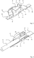
- the figure 1 shows an electrical connection terminal 1 according to the invention with an insulating material housing 2 in which a metallic contact frame 4 is accommodated.
- the insulating material housing 2 has at least one conductor entry opening 3 on one end face 19 for the insertion of an electrical conductor 5 ( figure 4 ).
- the terminal 1 has two poles, each with a conductor entry opening 3 and a contact frame 4 per pole executed.
- the connection terminal can also have any other desired number of poles.
- connection areas 16 of the contact frame 4 which contact corresponding contact sections 28, for example conductor tracks, of a printed circuit board 7 ( figure 2 ).
- the connection areas 16 are connected to the contact sections 28 in particular via a soldered connection (SMD soldered connection), but a plug-in connection is also conceivable.
- SMD soldered connection soldered connection
- a plug-in connection is also conceivable.
- the contact frame 4 held on the printed circuit board 7 can be seen.
- the illustration does not include the insulating material housing, so that the connection of the electrical conductor 5 to the contact frame 4 can be seen.
- the electrical conductor 5 is inserted through a ring-shaped, at least almost closed channel entrance 8 of the contact frame 4, with the stripped end 6 of the electrical conductor 5 being accommodated between the side walls of the channel-shaped contact frame 4 designed as leaf springs 9.
- the leaf springs 9 are bent out of a flat metal part and their free ends form a clamping edge 10 so that the two opposite clamping edges 10 of the leaf springs 9 form a clamping point for the electrical conductor 5 .
- the area from the channel entrance 8 of the contact frame 4, which adjoins the conductor insertion opening 3, to the terminal point formed by the clamping edges 10 defines a conductor insertion area 30.
- the structure of the contact frame 4 is in the figure 3 clearly visible, whereby it can be seen that to form the clamping edge 10 at the free end of the leaf spring 9, an additional exhibition 12 directed against the electrical conductor 5 is embossed or formed in order to improve the clamping effect.
- the contact frame 4 has a contact base 11, which is protruded or bent out of the surface of a flat metal part in such a way that it slopes upwards from the channel entrance 8 in the direction of the clamping point, i.e. essentially in the conductor insertion area 30, in the direction of an inserted conductor 5 is executed.
- a first contact area 16 adjoins the contact base 11 at one end at the channel entrance 8 and a second contact area 16 at the other end.
- FIG. 1 front latching hooks 14 formed on the annular channel entrance 8 can be seen, which engage in the corresponding front latching recesses 17 arranged there next to the conductor insertion opening 3 for the latching connection with the insulating material housing 2 .
- rear latching hooks 15 are provided on the contact base 11, which are arranged laterally on the contact base 11 and are preferably spaced apart from the printed circuit board 7 or from the plane formed by the contact areas 16 are and engage in recesses, not shown, of the insulating material housing 2 .
- the leaf spring 9 In the area of the free end of the leaf springs 9, on which the clamping edge 10 is formed, the leaf spring 9 has a starting bevel 12 on its longitudinal side facing away from the contact base 11, which is directed towards the outside of the connecting terminal 1.
- the starting bevels 12 of a contact frame 4 thus together form an upwardly directed, funnel-shaped receptacle facing away from the contact base 10 .
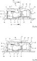
- the figures 4 and 5a and 5b each show a sectional view of the electrical connection terminal 1 composed of a contact frame 4 and an insulating material housing 2 according to the invention, wherein in FIG figure 4 in addition, a connected electrical conductor 5 is shown.
- the housing inner wall 31 has a sloping area, within which the housing inner wall 31 is designed to be inclined towards an inserted conductor 5 . This inclined area lies within the conductor entry area 30 defined above or can also extend over the entire conductor entry area 30 .
- the conductor entry area 30 has a funnel-shaped design at least in sections due to the design of the contact frame 4 with its leaf springs 9 and its contact base 10 as well as the housing inner wall 31 of the insulating material housing 2, it being clear that the funnel-shaped conductor entry area 30 is composed of the contact frame 4 and the insulating housing 2.
- the funnel-shaped conductor entry area 30 is at least almost completely closed on the peripheral side. There are narrow gaps only between the leaf springs 9 and the contact base 10 on the one hand and the leaf springs 9 and the inner wall 31 of the housing on the other hand.
- the cross section of the conductor entry area 30 is essentially rectangular or square, but it can also have any other desired shape, in particular round or at least round or arcuate in sections.
- the funnel-shaped conductor entry area 30 forms a guide for an electrical conductor 5 to be inserted, in particular for its stripped end 6, so that the stripped end can be fed to the terminal point in a targeted manner.
- the electrical connection terminal 1 can also be used for multi-wire electrical conductors 5, in particular when the terminal point formed by the clamping edges 10 is opened by an actuating element which is designed as a pusher 21 before the electrical conductor 5 is inserted.
- the individual wires of the multi-wire conductor 5 cannot deviate due to the conductor entry area 30 which is almost closed on the peripheral side and are held securely by the clamping edge 10 in a clamped manner.
- the end of the funnel-shaped section of the conductor insertion region 30 with the larger cross section that faces the conductor insertion opening 3 can also, if desired, serve as a stop for the insulated section of the electrical conductor 5.
- the funnel-shaped conductor entry area 30 is composed of the insulating housing 2 and the contact frame 4 or is formed by these two components, simple and effective conductor routing is achieved, with the contact frame 4 in particular being able to be designed very simply, compactly and with a saving in material.
- a pusher 21 can also be seen as an actuating element with a pusher arm 23 which is designed in one piece with the insulating material housing 2 .
- the pusher 21 acts on the starting bevels 12 and, when actuated, pushes these starting bevels 12 apart together with the leaf spring 9, ie when pressed with a force F in the direction of the insulating material housing 2.
- the clamping edges 10 of the leaf spring 9 are also pressed apart and the clamping point is opened for removing an electrical conductor 5 or for inserting an electrical conductor 5 , in particular a stranded conductor 5 .
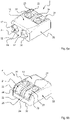
- the pusher arm 23 is as shown in FIG Figure 6a and 6b integrally formed on the insulating material housing 2 in the region of the rear side of the housing 20, preferably in its lower half facing away from the housing top side 18.
- the pusher arm 23 follows the contour of the insulating housing 2 so that a first pusher arm part 24 connected to the rear wall 20 of the housing runs approximately in the plane of the rear side 20 of the housing or approximately parallel thereto.
- the contour of the pusher arm 23 follows the contour of the transition from the rear side 20 of the housing to the top side 18 of the housing, so that a second pusher arm part 25, which is integrally connected to the first pusher arm part 24, is roughly in the plane of the top side 18 of the housing or roughly parallel thereto runs.
- the housing back 20 and the housing top 18 are arranged at an angle to one another, preferably the housing back 20 and the housing top 18 are arranged at least almost at right angles to one another.
- the pusher arm 23 is thus formed essentially as an angle.
- An actuating surface 27 is formed on the end of the second pusher arm part 25 facing away from the first pusher arm part. It can thus be seen that the pusher 21 is arranged in a housing recess 22 which extends over the rear side 20 of the housing and the top side 18 of the housing.
- the housing recess 22 is designed essentially as an opening so that the push button 21 can act on the contact frame 4 arranged inside the insulating housing 2 .
- the push button 21 as an actuating element is thus integrated with its angled design in the wall or surface of the insulating material housing 2 and represents a part of the insulating material housing 2 itself.
- the pusher arm 23 or the outer surface is essentially in the plane of the surface contour of the insulating material housing 2, both in the area of the upper side 18 of the housing and in the area of the rear side 20 of the housing.
- the pusher 21 protrudes slightly at least in relation to the top side 18 of the housing, as is shown in Figure 5a is recognizable.
- the starting bevels 12 of the contact frame 4 lie on the pusher 21 or, more precisely, on its pusher surface 26 ( figure 7 ) and deflect the pusher 21 outwards, so that the pusher arm 23 is under elastic pretension.
- the actuated state is shown, in which the pusher 21 is subjected to an actuating force F in the area of the trough-like actuating surface 27 .
- the pusher arm 23 elastically deforms essentially uniformly under the actuating force F, with the area of the pusher 21 with the actuating surfaces 26 entering between the leaf springs 9 .
- the pusher arm 23 has a substantially uniform strength or thickness for uniform elastic deformation.
- the pusher 21 is shifted from the position projecting beyond the housing top 18 into a position in which the pusher arm 23, in particular the second pusher arm part 25, dips into the insulating housing 2.
- the elastic bias of the pusher arm 23 is released and the pusher arm 23 is subjected to a reverse tension, so that the pusher arm tends to move outwards again in order to reach its initial position.
- the Figures 6a and 6b represent the insulating material housing 2 as an individual part, in particular the described design of the pusher 21 and the connection of the pusher arm 23 to the insulating material housing 2 are again clearly recognizable.
- the insulating material housing 2 has recesses 32 on the underside of the housing, into which the contact areas 16 of the contact frame 4 engage, so that these contact areas 16 can protrude beyond the rear side 20 and the front side 19 of the housing with the conductor entry openings 3 (see also figure 1 ).
- the underside of the housing of the assembled electrical connection terminals forms a substantially flat surface without protruding components.
- the insulating material housing 2 can thus reach directly up to the surface of the circuit board 7 or rest on the circuit board 7 when it is arranged on the circuit board 7 .
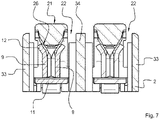
- the figure 7 once again illustrates the mode of action of the pusher 21 on the contact frame 4.
- the pusher surface 26 of the pusher 21 is essentially wedge-shaped and acts on the corresponding
- the wedge-shaped pusher surface 26 slides over the starting bevels 12, immersing itself between the leaf springs 9 and pushing them apart.
- the leaf springs 9 due to their restoring force, press the pusher 21 back into the starting position via the run-on bevels 12 and the corresponding actuating surface 26.
- the illustrated angular design of the pusher 21 enables a relatively long effective pusher arm 23 with a correspondingly long lever arm, which is particularly advantageous in the case of cramped installation space or very small electrical connection terminals with small insulating housings.
- the design of the pusher 21 according to the invention makes it possible in the first place to provide an effective pusher 21 for actuating a contact frame 4 .
- the tension with which the pusher arm 23 is acted upon can be kept small.
- the value of the preload is relatively small, since the deflection of the pusher arm 23 in the unactuated state is also relatively small.
- the deflection of the pusher arm 23 in the actuated position into the insulating housing 2 is also not significantly greater than in the unactuated state, so that the stresses to which the pusher arm 23 is subjected can also be kept relatively small.
- the pusher 21 can be kept very small overall and is therefore particularly suitable for very small connecting terminals.
- Overload protection for both the leaf springs 9 and the pusher 21 can also be implemented with the illustrated embodiment of the electrical terminal. How out figure 7 As can be seen, when the leaf springs 9 are sufficiently deflected, the bevels 12 arranged on the leaf springs 9 will strike the side walls 33 of the insulating material housing 2 and/or one or more intermediate walls 34 of the insulating material housing 2 arranged between the poles of the connection terminal 1. The side walls 33 and/or intermediate walls 34 thus limit a deflection of the leaf springs 9 and thus prevent them from being overloaded and thus not being able to deform plastically or break.
- overload protection for the pusher 21 or the pusher arm can also be implemented. Due to the limited deflection of the leaf springs 9, only a limited space can arise between two mutually associated leaf springs. If the maximum width of the section of the pusher arm 23, which dips between the leaf springs 9, is greater than the space between the maximally deflected leaf springs 9, the pusher arm 23 can only be deflected to a limited extent, so that it cannot be subjected to excessive stress and breakage of the pusher arm 23 is effectively avoided.
- Overload protection for the pusher 21 or its pusher arm 23 can also be achieved by providing a stop on the section of the pusher arm 23 that dips between the leaf springs 9, which stops at a maximum deflection of the pusher arm or at a maximum immersion depth on the leaf springs 9 or rests on the ramps 12, so that further deflection of the pusher arm is prevented and damage to the pusher 21 is avoided.
Landscapes
- Connections Arranged To Contact A Plurality Of Conductors (AREA)
- Coupling Device And Connection With Printed Circuit (AREA)
- Details Of Connecting Devices For Male And Female Coupling (AREA)
- Push-Button Switches (AREA)
Description
- Die Erfindung betrifft für eine elektrische Anschlussklemme, wobei die elektrische Anschlussklemme einen Kontaktrahmen mit einem Leiterklemmanschluss für einen elektrischen Leiter umfasst und der Leiterklemmanschluss am Kontaktrahmen durch mindestens ein Federelement gebildet wird, dessen freies Ende eine gegen den elektrischen Leiter gerichtete und mit einer Klemmkraft beaufschlagten Klemmkante bildet.
- Die
ES 2 159 247 A1 EP 1 182 750 A2 offenbart. Aus derDE 33 46 027 C2 ist eine elektrische Anschlussklemme bekannt. Aus derDE 199 14 308 A1 ist eine elektrische Anschlussbaueinheit bekannt, bei der ein Kontakteinsatz insgesamt schräg gestellt sein kann. -
US 2008/0153344 A1 offenbart eine SMD-Anschlussklemme, mit einem zylinderförmigen Kontaktelement, an das sich beidseits SMD-Kontaktflächen anschließen. Ein elektrischer Leiter wird durch die zylinderförmige Metallhülse zu einer Klemmstelle geführt, die durch eine aus der Metallhülse ausgeformte und abgebogene Blattfeder gebildet wird. - Aufgabe der Erfindung ist es, eine elektrische Anschlussklemme für den Anschluss eines elektrischen Leiters bereitzustellen, welche durch eine verbesserte Leiterführung eine sichere Klemmung des elektrischen Leiters gewährleistet und gleichzeitig einen einfachen Aufbau aufweist.
- Gelöst wird die Aufgabe erfindungsgemäß durch die Merkmale des Anspruchs 1.
- Die elektrische Anschlussklemme weist einen in einem Isolierstoffgehäuse angeordneten Kontaktrahmen mit einem Leiterklemmanschluss für einen elektrischen Leiter auf. Der Leiterklemmanschluss wird am Kontaktrahmen durch mindestens ein Federelement gebildet, dessen freies Ende eine gegen den elektrischen Leiter gerichtete und mit einer Klemmkraft beaufschlagten Klemmkante bildet.
- Der Kontaktrahmen weist einen Kontaktboden auf, wobei sich an den Kontaktboden einenends am Kanaleingang ein erster Kontaktbereich und anderenends ein zweiter Kontaktbereich anschließt. Der erste und der zweite Kontaktbereich bilden eine Ebene. Der Kontaktboden ist derart aus der Fläche eines ebenen Metallteils herausgestellt, dass der Kontaktboden von dem Kanaleingang, durch den ein elektrischer Leiter in die elektrische Anschlussklemme einführbar ist, in Richtung der Klemmstelle des Leiterklemmanschlusses ansteigend in Richtung eines eingesteckten Leiters geneigt ausgeführt ist.
- Die Gehäuseinnenwandung des Isolierstoffgehäuses weist gegenüberliegend zum geneigt ausgeführten Abschnitt des Kontaktbodens einen schrägen Bereich auf, der gegen einen eingesteckten Leiter geneigt ausgeführt ist und einen trichterförmigen Leitereinführungsbereich bildet.
- Der Leiterklemmanschluss kann z.B. durch ein Einwirken eines optionalen Drückers auf das mindestens eine Federelement geöffnet werden, indem durch den Drücker eine Kraft entgegen der Klemmkraft auf das Federelement aufgebracht wird. Dabei kann der Drücker aus einem Drückerarm bestehen, wobei der Drückerarm mit seinem einem Ende an das Isolierstoffgehäuse angebunden ist und wobei sich der Drückerarm entlang mindestens eines Teilabschnitts von zwei in einem Winkel zueinander angeordneten Oberflächen des Isolierstoffgehäuses erstreckt.
- Die erfindungsgemäße Ausbildung des Drückers, welcher somit winkelförmig ausgeführt ist, ermöglicht einen verhältnismäßig langen wirksamen Drückerarm mit einem dementsprechend langen Hebelarm, was insbesondere bei beengten Bauraumverhältnissen oder sehr kleinen elektrischen Anschlussklemmen mit kleinen Isolierstoffgehäusen von Vorteil ist. So wird es insbesondere bei miniaturisierten Anschlussklemmen durch die erfindungsgemäße Ausbildung des Drückers überhaupt erst ermöglicht, einen wirksamen Drücker für die Betätigung eines Kontaktrahmens vorzusehen.
- In einer bevorzugten Ausführungsform sind die beiden in einem Winkel zueinander angeordneten Oberflächen zumindest nahezu senkrecht zueinander angeordnet sind. Somit ist der Drückerarm bevorzugt aus einem ersten, dem Verlauf einer Gehäuserückseite angepassten Drückerarmteil und einem zweiten, den Verlauf einer Gehäuseoberfläche angepassten Drückerarmteil gebildet. Des Weiteren ist der Drückerarm damit bevorzugt in einer Ausnehmung des Isolierstoffgehäuses angeordnet.
- In einer besonders vorteilhaften Ausführungsform weist der Drückerarm eine Betätigungsfläche mit einer muldenförmigen Ausnehmung auf, so dass auf einfache Weise eine Ansetzmöglichkeit für ein Betätigungswerkzeug geschaffen ist, so dass der Drücker sicher betätigt werden kann.
- Bevorzugt ist der Drückerarm elastisch verformbar gestaltet, so dass eine einfache Bewegung bzw. Auslenkung des Drückers bei minimalem konstruktivem Aufwand gewährleistet werden kann.
- In einer bevorzugten Ausführungsform ist das Federelement als zumindest eine Blattfeder oder ein Federschenkel ausgebildet, so dass in der bevorzugten Ausbildung des Kontaktrahmens in Art eines Kanals und der Kontaktrahmen zur Bildung eines Leiterklemmanschlusses an jeder Seitenwand jeweils eine Blattfeder in Art einer aus einem flachen Metallteil ausgestanzten Zunge aufweist, welche aus der Ebene des flachen Metallteil herausgebogen ist, derart, dass das freie Ende der Blattfeder eine gegen den elektrischen Leiter gerichtete Klemmkante bildet. Somit wird die elektrische Anschlussklemme aus lediglich zwei Bauteilen, dem Isolierstoffgehäuse mit integriertem Drücker sowie einem einteiligen Kontaktrahmen gebildet, so dass ein einfacher Aufbau und eine einfache Montage mit niedrigen Kosten gewährleistet werden kann.
- Bevorzugt ist an den Blattfedern jeweils eine zur Außenseite der elektrischen Anschlussklemme gerichtete Anlaufschräge angeformt, welche zueinander trichterförmig ausgestellt sind. Somit kann der Drücker auf einfache Weise zwischen die Blattfedern eingedrückt werden, um den Klemmanschluss des elektrischen Leiters durch Auseinanderdrücken der Blattfedern zu öffnen. Hierzu weist der Drücker bevorzugt eine korrespondierende keilförmige Drückerfläche auf, welche an dem am Isolierstoffgehäuse angebunden Ende abgewandte Ende des Drückerarms ausgebildet ist.
- Im montierten Zustand der elektrischen Anschlussklemme, in dem der Kontaktrahmen in dem Isolierstoffgehäuse eingesetzt ist, steht der Drückerarm unter einer Vorspannung, so dass der Drückerarm über die Oberfläche der Gehäuseoberseite hervorsteht. Dadurch, dass der Drückerarm im unbetätigten Zustand einer Vorspannung unterworfen ist, kann die Spannung, mit welcher der Drückerarm beaufschlagt wird, klein gehalten werden. Der Wert der Vorspannung ist relativ klein, da die Auslenkung des Drückerarms im unbetätigten Zustand auch relativ klein ist. Die Auslenkung des Drückerarms in der betätigten Stellung in das Isolierstoffgehäuse hinein ist auch nicht Wesentlich viel größer als im unbetätigten Zustand, so dass die Spannungen, welcher der Drückerarm unterworfen wird, insgesamt klein gehalten werden können. Die niedrig gehaltenen Spannungswerte innerhalb des Drückers bzw. der Drückerarms tragen dazu bei, dass der Drücker und damit auch das Isolierstoffgehäuse klein gehalten werden kann.
- Um eine Beschädigung, insbesondere ein Brechen, des zumindest einen Federelements und/oder des Drückers wirksam zu vermeiden ist in einer bevorzugten Ausführungsform ein Überlastschutz hierfür vorgesehen. Vorteilhafterweise ist dabei die Auslenkung des als Blattfederfeder ausgebildeten Federelements durch Seitenwände und/oder Zwischenwände des Isolierstoffgehäuses begrenzbar. Weiterhin vorteilhaft ist die Begrenzung der Auslenkung des Drückerarms des Drückers durch eine Anlage des Drückerarms an zumindest einem als Blattfeder ausgebildetem Federelement. Diese Ausbildungsformen ermöglichen einen Überlastschutz ohne wesentliche Anpassungen der elektrischen Anschlussklemme und sind daher kostengünstig.
- Nachfolgend wird die Erfindung anhand eines in den Figuren dargestellten Ausführungsbeispieles näher erläutert. Es zeigen
- Fig.1 :
- eine erfindungsgemäße Anschlussklemme im Zusammenbau in perspektivischer Darstellung,
- Fig.2 :
- eine erfindungsgemäße auf deiner Leiterplatte angeordnete Anschlussklemme mit eingestecktem Leiter ohne Isolierstoffgehäuse,
- Fig.3 :
- eine perspektivische Ansicht des Kontaktrahmens,
- Fig. 4:
- eine perspektivische Schnittdarstellung der erfindungsgemäßen auf einer Leiterplatte angeordneten Anschlussklemme mit eingestecktem elektrischem Leiter,
- Fig. 5a:
- eine Schnittdarstellung der erfindungsgemäßen Anschlussklemme entsprechend des Schnittes IV-IV aus
Figur 1 mit unbetätigtem Drücker, - Fig. 5b:
- eine Schnittdarstellung der erfindungsgemäßen Anschlussklemme entsprechend des Schnittes IV-IV aus
Figur 1 mit betätigtem Drücker, - Fig. 6a:
- eine erste perspektivische Ansicht des Isolierstoffgehäuses,
- Fig. 6b:
- eine zweite perspektivische Ansicht des Isolierstoffgehäuses,
- Fig. 7:
- eine Schnittdarstellung der erfindungsgemäßen Anschlussklemme entsprechend des Schnittes VII-VII aus Figur a.
- Die
Figur 1 zeigt eine erfindungsgemäße elektrische Anschlussklemme 1 mit einem Isolierstoffgehäuse 2, in welchem ein metallischer Kontaktrahmen 4 aufgenommen ist. Das Isolierstoffgehäuse 2 hat an einer Stirnseite 19 zumindest eine Leitereinführungsöffnung 3 für das Einstecken eines elektrischen Leiters 5 (Figur 4 ). In dem dargestellten Ausführungsbeispiel ist die Anschlussklemme 1 zweipolig mit jeweils einer Leitereinführungsöffnung 3 und einem Kontaktrahmen 4 pro Pol ausgeführt. Die Anschlussklemme kann aber auch jede andere beliebige Polzahl aufweisen. - Erkennbar sind in der
Figur 1 ferner Anschlussbereiche 16 des Kontaktrahmens 4, welche entsprechende Kontaktabschnitte 28, z.B. Leiterbahnen, einer Leiterplatte 7 kontaktieren (Figur 2 ). Die Anschlussbereiche 16 sind mit den Kontaktabschnitten 28 dabei insbesondere über eine Lötverbindungen (SMD-Lötverbindung) verbunden, denkbar ist aber auch eine Steckverbindung. In derFigur 2 ist der auf der Leiterplatte 7 gehaltene Kontaktrahmen 4 ersichtlich. In der Darstellung wurde auf das Isolierstoffgehäuse verzichtet, so dass der Anschluss des elektrischen Leiter 5 an dem Kontaktrahmen 4 erkennbar ist. Der elektrische Leiter 5 wird durch einen ringförmig gebogenen, zumindest nahezu geschlossen ausgeführten Kanaleingang 8 des Kontaktrahmes 4 eingeführt, wobei das abisolierte Ende 6 des elektrischen Leiters 5 zwischen den als Blattfedern 9 ausgebildeten Seitenwänden des kanalförmigen Kontaktrahmens 4, aufgenommen ist. Die Blattfedern 9 sind dabei aus einem flachen Metallteil herausgebogen und deren freie Enden bilden eine Klemmkante 10, so dass die zwei gegenüberliegende Klemmkanten 10 der Blattfedern 9 eine Klemmstelle für den elektrischen Leiter 5 bilden. Der Bereich von dem sich an die Leitereinführungsöffnung 3 anschließenden Kanaleingang 8 des Kontaktrahmens 4 bis zu der von den Klemmkanten 10 gebildeten Klemmstelle definiert dabei einen Leitereinführungsbereich 30. - Der Aufbau des Kontaktrahmens 4 ist in der
Figur 3 deutlich sichtbar, wobei erkennbar ist, dass zur Bildung der Klemmkante 10 am freien Ende der Blattfeder 9 eine zusätzliche, gegen den elektrischen Leiter 5 gerichtete Ausstellung 12 angeprägt bzw. angeformt ist, um die Klemmwirkung zu verbessern. Ferner weist der Kontaktrahmen 4 einen Kontaktboden 11 auf, welcher derart aus der Fläche eines ebenen Metallteils herausgestellt bzw. heraus gebogen ist, dass dieser vom Kanaleingang 8 in Richtung der Klemmstelle, also im Wesentlichen im Leitereinführbereich 30, ansteigend in Richtung eines eingesteckten Leiters 5 geneigt ausgeführt ist. An den Kontaktboden 11 schließt sich einenends am Kanaleingang 8 ein erster Kontaktbereich 16 an und anderenends ein zweiter Kontaktbereich 16 an. Zudem sind inFigur 3 am ringförmigen Kanaleingang 8 angeformte vordere Rasthaken 14 erkennbar, welche zur verrastenden Verbindung mit dem Isolierstoffgehäuse 2 in dort neben der Leitereinführungsöffnung 3 angeordnete korrespondierende vordere Rastausnehmungen 17 eingreifen. Im Bereich zwischen der durch die Klemmkanten 10 gebildete Klemmstelle und dem vom ringförmigen Kanaleingang abgewandten hinteren Kontaktbereich 16 sind am Kontaktboden 11 hintere seitlich am Kontaktboden 11 angeordnete Rasthaken 15 vorgesehen, welche von der Leiterplatte 7 bzw. von der durch die Kontaktbereiche 16 gebildeten Ebene vorzugsweise beabstandet sind und in nicht dargestellte Rastausnehmungen des Isolierstoffgehäuses 2 eingreifen. - Im Bereich des freien Endes der Blattfedern 9, an welchem jeweils die Klemmkante 10 ausgebildet ist, weist die Blattfeder 9 jeweils an ihrer dem Kontaktboden 11 abgewandten Längsseite eine Anlaufschräge 12 auf, welche jeweils zur Außenseite der Anschlussklemme 1 gerichtet ist. Die Anlaufschrägen 12 eines Kontaktrahmens 4 bilden somit zusammen eine nach oben gerichtete, vom Kontaktboden 10 abgewandte trichterförmige Aufnahme.
- Die
Figuren 4 sowie 5a und 5b zeigen jeweils eine Schnittdarstellung der erfindungsgemäßen aus einem Kontaktrahmen 4 und einem Isolierstoffgehäuse 2 zusammengesetzten elektrischen Anschlussklemme 1, wobei in derFigur 4 zusätzlich ein angeschlossener elektrischer Leiter 5 dargestellt ist. In diesen Figuren ist erkennbar, dass die Gehäuseinnenwandung 31 einen schrägen Bereich aufweist, innerhalb dessen die Gehäuseinnenwandung 31 gegen einen eingesteckten Leiter 5 geneigt ausgeführt ist. Dieser geneigte Bereich liegt innerhalb des oben definierten Leitereinführungsbereiches 30 oder kann sich auch über den gesamten Leitereinführungsbereich 30 erstrecken. - Es ist in diesen Darstellungen ferner erkennbar, dass der Leitereinführungsbereich 30 auf Grund der Gestaltung des Kontaktrahmens 4 mit seinen Blattfedern 9 und seinem Kontaktboden 10 sowie der Gehäuseinnenwandung 31 des Isolierstoffgehäuses 2 eine zumindest abschnittsweise trichterförmige Ausbildung aufweist, wobei deutlich wird, dass der trichterförmige Leitereinführungsbereich 30 aus dem Kontaktrahmen 4 und dem Isolierstoffgehäuse 2 zusammengesetzt ist. Der trichterförmige Leitereinführungsbereich 30 ist dabei umfangsseitig zumindest nahezu vollständig geschlossen. Lediglich zwischen den Blattfedern 9 und dem Kontaktboden 10 einerseits und den Blattfedern 9 und der Gehäuseinnenwandung 31 andererseits sind schmale Spalte vorhanden. Der Querschnitt des Leitereinführungsbereiches 30 ist im Ausführungsbeispiel im Wesentlichen rechteckig bzw. quadratisch ausgeführt, kann allerdings auch jede beliebige andere Form aufweisen, insbesondere rund oder zumindest abschnittsweise rund oder bogenförmig.
- Der trichterförmige Leitereinführungsbereich 30 bildet dabei für einen einzusteckenden elektrischen Leiter 5, insbesondere für dessen abisoliertes Ende 6, eine Führung, so dass das abisolierte Ende zielgerichtet der Klemmstelle zugeführt werden kann. Die elektrische Anschlussklemme 1 ist auch für mehrdrähtige elektrische Leiter 5 verwendbar, insbesondere dann, wenn die durch die Klemmkanten 10 gebildete Klemmstelle durch ein Betätigungselement, welches als ein Drücker 21 ausgebildet ist, vor dem Einstecken des elektrischen Leiters 5 geöffnet wird. Die einzelnen Drähte des mehrdrähtigen Leiters 5 können auf Grund des umfangsseitig nahezu geschlossen Leitereinführungsbereiches 30 nicht ausweichen und werden sicher von der Klemmkante 10 klemmend gehalten. Das der Leitereinführungsöffnung 3 zugewande Ende des trichterförmigen Abschnitts des Leitereinführungsbereichs 30 mit dem größeren Querschnitt kann dabei auch, wenn erwünscht, als ein Anschlag für das den isolierten Abschnitt des elektrischen Leiters 5 dienen.
- Dadurch, dass der trichterförmige Leitereinführungsbereich 30 zusammengesetzt ist aus dem Isolierstoffgehäuse 2 und dem Kontaktrahmen 4 bzw. von diesen beiden Baueilen gebildet wird, wird eine einfache und wirkungsvolle Leiterführung erzielt, wobei insbesondere der Kontaktrahmen 4 sehr einfach, kompakt und materialsparend ausgeführt werden kann.
- In den
Figuren 4 ,5a und 5b ist ferner ein Drücker 21 als Betätigungselement mit einem Drückerarm 23 erkennbar, welcher einstückig mit dem Isolierstoffgehäuse 2 ausgeführt ist. Der Drücker 21 wirkt dabei auf Anlaufschrägen 12 und drückt bei Betätigung diese Anlaufschrägen 12 zusammen mit den Blattfeder 9, d.h. bei einem Eindrücken mit einer Kraft F in Richtung auf das Isolierstoffgehäuse 2, auseinander. Somit werden auch die Klemmkanten 10 der Blattfeder 9 auseinandergedrückt und die Klemmstelle zum Entnehmen eines elektrischen Leiters 5 oder zum Einstecken einen elektrischen Leiters 5, insbesondere eines mehrdrähtigen Leiters 5 geöffnet. - Der Drückerarm 23 ist entsprechend der Darstellung nach
Figur 6a und 6b einstückig im Bereich der Gehäuserückseite 20, vorzugsweise in deren unteren, der Gehäuseoberseite 18 abgewandten Hälfte, an dem Isolierstoffgehäuse 2 angeformt. Der Drückerarm 23 folgt dabei der Kontur des Isolierstoffgehäuses 2, so dass ein erstes an der Gehäuserückwand 20 angebundenes Drückerarmteil 24 in etwa in der Ebene der Gehäuserückseite 20 oder in etwa parallel hierzu verläuft. Die Kontur des Drückerarms 23 folgt im weiteren Verlauf der Kontur des Übergangs von der Gehäuserückseite 20 zur Gehäuseoberseite 18, so dass ein zweites Drückerarmteil 25, welches mit dem ersten Drückerarmteil 24 einstückig verbunden ist in etwa in der Ebene der Gehäuseoberseite 18 oder in etwa parallel hierzu verläuft. Die Gehäuserückseite 20 und die Gehäuseoberseite 18 sind dabei in einem Winkel zueinander angeordnet, vorzugsweise sind die Gehäuserückseite 20 und die Gehäuseoberseite 18 zumindest nahezu rechtwinklig zueinander angeordnet. Der Drückerarm 23 ist somit im Wesentlichen als ein Winkel ausgebildet. An dem zweiten Drückerarmteil 25 ist an seinem dem ersten Drückerarmteil abgewandten Ende eine Betätigungsfläche 27 angeformt, welche im vorliegenden Ausführungsbeispiel muldenförmig ausgebildet ist, aber alternativ auch jede andere beliebige Form, z.B. schlitz oder kreuzschlitzförmig, annehmen kann. Es ist somit erkennbar, dass der Drücker 21 in einer Gehäuseausnehmung 22, welche sich über Gehäuserückseite 20 und die Gehäuseoberseite 18 erstreckt, angeordnet ist. Die Gehäuseausnehmung 22 ist dabei im Wesentlichen als Durchbruch gestaltet, damit der Drücker 21 auf den im Inneren des Isolierstoffgehäuses 2 angeordneten Kontaktrahmen 4 einwirken kann. Der Drücker 21 als Betätigungselement ist somit mit seiner abgewinkelten Ausführung in die Wandung bzw. Oberfläche des Isolierstoffgehäuses 2 integriert und stellt einen Teil des Isolierstoffgehäuses 2 selbst dar. - Im nicht montierten Zustand befindet sich der Drückerarm 23 bzw. des äußere Oberfläche im Wesentlichen in der Ebene der Oberflächenkontur des Isolierstoffgehäuses 2, sowohl im Bereich der Gehäuseoberseite 18 als auch im Bereich der Gehäuserückseite 20. Im montierten mit dem im Isolierstoffgehäuse 2 eingesetzten Kontaktrahmen 4 und nicht betätigten Zustand steht der Drücker 21 dagegen zumindest gegenüber der Gehäuseoberseite 18 etwas heraus, wie dies in
Figur 5a erkennbar ist. Die Anlaufschrägen 12 des Kontaktrahmens 4 liegen dabei am Drücker 21 oder genauer gesagt an dessen Drückerfläche 26 (Figur 7 ) an und lenken den Drücker 21 nach außen aus, so dass der Drückerarm 23 unter einer elastischen Vorspannung steht. In derFigur 5b ist der betätigte Zustand dargestellt, in dem der Drücker 21 mit einer Betätigungskraft F im Bereich der muldenartigen Betätigungsfläche 27 beaufschlagt ist. Erkennbar ist, dass der Drückerarm 23 sich unter der Betätigungskraft F im Wesentlichen gleichmäßig elastisch verformt, wobei der Bereich des Drückers 21 mit den Betätigungsflächen 26 zwischen die Blattfedern 9 eintaucht. Der Drückerarm 23 weist für die gleichmäßige elastische Verformung eine im Wesentlichen gleichmäßige Stärke oder Dicke auf. Während des Betätigungsvorganges, d.h. des Eindrückens des Drückers 21 wird der Drücker 21 aus der über die Gehäuseoberseite 18 hinausragenden Stellung in eine Stellung verlagert, in der der Drückerarm 23, insbesondere das zweite Drückerarmteil 25, in das Isolierstoffgehäuse 2 eintaucht. Dabei wird die elastischen Vorspannung des Drückerarms 23 aufgehoben und der Drückerarm 23 einer umgekehrten Spannung unterworfen, so dass der Drückerarm bestrebt ist, sich wieder nach außen zu bewegen, um in seine Ausgangsstellung zu gelangen. - Die
Figuren 6a und 6b stellen das Isolierstoffgehäuse 2 als Einzelteil dar, wobei insbesondere die beschriebene Ausbildung des Drückers 21 und die Anbindung des Drückerarms 23 an das Isolierstoffgehäuse 2 nochmals deutlich erkennbar sind. Ferner ist erkennbar, dass das Isolierstoffgehäuse 2 an einer Gehäuseunterseite jeweils Ausnehmungen 32 aufweist, in welche die Kontaktbereiche 16 des Kontaktrahmens 4 eingreifen, so dass diese Kontaktbereiche 16 über die Gehäuserückseite 20 und die Gehäusevorderseite 19 mit den Leitereinführungsöffnungen 3 hinausragen können (siehe auchFigur 1 ). Gleichzeitig wird erreicht, dass die Gehäuseunterseite der zusammengesetzten elektrischen Anschlussklemmen eine im Wesentlichen ebene Fläche ohne herausstehende Bauteile bildet. Das Isolierstoffgehäuse 2 kann somit im auf der Leiterplatte 7 angeordneten Zustand unmittelbar bis zu Oberfläche der Leiterplatte 7 reichen bzw. auf der Leiterplatte 7 aufliegen. - Die
Figur 7 verdeutlicht nochmals die Wirkungsweise des Drückers 21 auf den Kontaktrahmen 4. Die Drückerfläche 26 des Drückers 21 ist im Wesentlichen keilförmig ausgebildet und wirkt auf die korrespondierenden schräg gestellten Anlaufschrägen 12 des Kontaktrahmens 4. Bei einer Beaufschlagung des Drückers 21 mit einer Kraft F über die Betätigungsfläche 27 gleitet die keilförmige Drückerfläche 26 über die Anlaufschrägen 12, taucht dabei zwischen die Blattfedern 9 ein und drückt diese auseinander. Sobald die Betätigungskraft F vom Drücker 21 weggenommen wird, drücken die Blattfedern 9 auf Grund ihrer Rückstellkraft den Drücker 21 über die Anlaufschrägen 12 sowie der dazu korrespondierenden Betätigungsfläche 26 wieder zurück in die Ausgangslage. - Die dargestellte winkelförmige Ausbildung des Drückers 21 ermöglicht einen verhältnismäßig langen wirksamen Drückerarm 23 mit einem dementsprechend langen Hebelarm, was insbesondere bei beengten Bauraumverhältnissen oder sehr kleinen elektrischen Anschlussklemmen mit kleinen Isolierstoffgehäusen von Vorteil ist. So wird es insbesondere bei miniaturisierten Anschlussklemmen durch die erfindungsgemäße Ausbildung des Drückers 21 überhaupt erst ermöglicht, einen wirksamen Drücker 21 für die Betätigung eines Kontaktrahmens 4 vorzusehen.
- Dadurch, dass der Drückerarm 23 im unbetätigten Zustand einer Vorspannung unterworfen ist, kann die Spannung, mit welcher der Drückerarm 23 beaufschlagt wird, klein gehalten werden. Der Wert der Vorspannung ist relativ klein, da die Auslenkung des Drückerarms 23 im unbetätigten Zustand auch relativ klein ist. Die Auslenkung des Drückerarms 23 in der betätigten Stellung in das Isolierstoffgehäuse 2 hinein ist auch nicht Wesentlich viel größer als im unbetätigten Zustand, so dass die Spannungen, welcher der Drückerarm 23 unterworfen wird, auch verhältnismäßig klein gehalten werden können. Würde dagegen der gesamte Betätigungsweg auf einen spannungslosen Drückerarm 23 aufgegeben werden, wäre die auf den Drückerarm 23 wirkende Spannung wesentlich größer, so dass auch der Drückerarm 23 insgesamt größer dimensioniert werden müsste. Man erkennt also, dass mit der vorliegenden Anordnung des Drückers 21 innerhalb der Anschlussklemme 1 und dessen Zusammenwirken mit dem Kontaktrahmen 4, der Drücker 21 insgesamt sehr klein gehalten werden kann und damit insbesondere für sehr klein bauende Anschlussklemmen geeignet ist.
- Mit der dargestellten Ausführung der elektrischen Klemme kann auch ein Überlastschutz sowohl für die Blattfedern 9 als auch für den Drücker 21 realisiert werden. Wie aus
Figur 7 ersichtlich ist, werden die an den Blattfedern 9 angeordneten Anlaufschrägen 12 bei einer hinreichenden Auslenkung der Blattfedern 9 an den Seitenwänden 33 des Isolierstoffgehäuses 2 und/oder einer oder mehrerer zwischen den Polen der Anschlussklemme1 angeordneter Zwischenwände 34 des Isolierstoffgehäuses 2 anstoßen. Die Seitenwände 33 und/oder Zwischenwände 34 begrenzen somit eine Auslenkung der Blattfedern 9 und verhindern so, dass diese überlastet werden und sich somit nicht plastisch verformen oder brechen können. - Gleichzeitig kann aber auch ein Überlastschutz für den Drücker 21 bzw. dem Drückerarm realisiert werden. Durch die begrenzte Auslenkung der Blattfedern 9 kann zwischen zwei zueinander zugeordneten Blattfedern lediglich ein begrenzter Zwischenraum entstehen. Sofern die maximale Breite des Abschnitts des Drückerarms 23, welcher zwischen die Blattfedern 9 eintaucht größer ist als der Zwischenraum zwischen den maximal ausgelenkten Blattfedern 9, kann der Drückerarm 23 nur begrenzt ausgelenkt werden, so dass dieser auch keiner übermäßigen Belastung unterworfen werden kann und ein Brechen des Drückerarms 23 wirksam vermieden wird.
- Ein Überlastschutz für den Drücker 21 bzw. dessen Drückerarm 23 kann auch dadurch erreicht werden, dass an dem zwischen die Blattfedern 9 eintauchenden Abschnitt des Drückerarms 23 ein Anschlag vorgesehen wird, der bei einer maximalen Auslenkung des Drückerarms bzw. bei einer maximalen Eintauchtiefe auf den Blattfedern 9 oder auf den Anlaufschrägen 12 aufliegt, so dass eine weitere Auslenkung des Drückerarms verhindert wird und eine Beschädigung des Drückers 21 vermieden wird.
-
- 1
- Anschlussklemme
- 2
- Isolierstoffgehäuse
- 3
- Leitereinführungsöffnung
- 4
- Kontaktrahmen
- 5
- elektrischer Leiter
- 6
- abisoliertes Ende des elektrischen Leiters
- 7
- Leiterplatte
- 8
- Kanaleingang
- 9
- Blattfedern
- 10
- Klemmkante
- 11
- Kontaktboden
- 12
- Anlaufschräge
- 13
- Ausstellung des freien Endes der Blattfeder
- 14
- vorderer Rasthaken
- 15
- hinterer Rasthaken
- 16
- Kontaktbereiche
- 17
- vordere Rastausnehmung
- 18
- Gehäuseoberseite
- 19
- Stirnseite
- 20
- Gehäuserückseite
- 21
- Drücker
- 22
- Gehäuseausnehmung
- 23
- Drückerarm
- 24
- erstes Drückerarmteil
- 25
- zweites Drückerarmteil
- 26
- Drückerfläche
- 27
- Betätigungsfläche
- 28
- Leiterbahn, Kontaktabschnitt
- 30
- Leitereinführbereich
- 31
- Gehäuseinnenwandung
- 32
- Ausnehmung
- 33
- Seitenwand
- 34
- Zwischenwand
Claims (18)
- Elektrische Anschlussklemme, wobei- die elektrische Anschlussklemme (1) einen Kontaktrahmen (4) mit einem Leiterklemmanschluss für einen elektrischen Leiter (5) umfasst und- der Leiterklemmanschluss am Kontaktrahmen (4) durch mindestens ein Federelement (9) gebildet wird, dessen freies Ende eine gegen den elektrischen Leiter (5) gerichtete und mit einer Klemmkraft beaufschlagten Klemmkante (10) bildet- der Kontaktrahmen (4) einen Kontaktboden (11) aufweist,wobei der Kontaktboden (11) derart aus der Fläche eines ebenen Metallteils herausgestellt ist, dass der Kontaktboden (11) von dem Kanaleingang (8), durch den ein elektrischer Leiter (5) in die elektrische Anschlussklemme (1) einführbar ist, in Richtung der Klemmstelle des Leiterklemmanschlusses ansteigend in Richtung eines eingesteckten Leiters (5) geneigt ausgeführt ist, wobei die elektrische Anschlussklemme ein Isolierstoffgehäuse (2) aufweist, in dem der Kontaktrahmen (4) mit dem Leiterklemmanschluss angeordnet ist,wobei sich an den Kontaktboden (11) einenends am Kanaleingang (8) ein erster Kontaktbereich (16) und anderenends ein zweiter Kontaktbereich (16) anschließt, dadurch gekennzeichnet, dass der erste und der zweite Kontaktbereich (16) eine Ebene bilden und dass die Gehäuseinnenwandung (31) des Isolierstoffgehäuses (2) gegenüberliegend zum geneigt ausgeführten Abschnitt des Kontaktbodens (11) einen schrägen Bereich aufweist, der gegen einen eingesteckten Leiter (5) geneigt ausgeführt ist und einen aus dem Kontaktrahmen (4) und dem Isolierstoffgehäuse (2) zusammengesetzten trichterförmigen Leitereinführungsbereich bildet, der aufgrund der Gestaltung des Kontaktrahmens (4) mit seinem als Blattfedern ausgebildeten Federelement (9) und seinem Kontaktboden (11) sowie der Gehäuseinnenwandung (31) des Isolierstoffgehäuses (2) eine zumindest abschnittsweise trichterförmige Ausbildung aufweist.
- Elektrische Anschlussklemme nach Anspruch 1, dadurch gekennzeichnet, dass ein Querschnitt des Leitereinführungsbereichs (30) der elektrischen Anschlussklemme im Wesentlichen rechteckig oder quadratisch ausgeführt ist.
- Elektrische Anschlussklemme nach einem der Ansprüche 1 bis 2, dadurch gekennzeichnet, dass der Kontaktrahmen (4) in Art eines Kanals ausgebildet und wobei der Kontaktrahmen (4) zur Bildung eines Leiterklemmanschlusses an jeder Seitenwand jeweils eine Blattfeder (9) in Art einer aus einem flachen Metallteil ausgestanzten Zunge aufweist, welche aus der Ebene des flachen Metallteil herausgebogen ist, derart, dass das freie Ende der Blattfeder (9) eine gegen den elektrischen Leiter (5) gerichtete Klemmkante (10) bildet.
- Elektrische Anschlussklemme nach Anspruch 3, dadurch gekennzeichnet, dass zwischen den Blattfedern (9) und dem Kontaktboden (11) schmale Spalte vorhanden sind.
- Elektrische Anschlussklemme nach einem der Ansprüche 3 bis 4, dadurch gekennzeichnet, dass an den Blattfedern (9) jeweils eine zur Außenseite der elektrischen Anschlussklemme (1) gerichtete Anlaufschräge (12) angeformt ist, welche trichterförmig zueinander ausgestellt sind.
- Elektrische Anschlussklemme nach einem der Ansprüche 1 bis 5, dadurch gekennzeichnet, dass die elektrische Anschlussklemme eine Betätigungseinrichtung aufweist, wobei die Betätigungseinrichtung ein als Drücker (21) ausgebildetes Betätigungselement umfasst, welches einstückig mit dem Isolierstoffgehäuse (2) verbunden ist, und der Leiterklemmanschluss durch ein Einwirken des Drückers (21) auf das mindestens eine Federelement (9) geöffnet werden kann, indem durch den Drücker (21) eine Kraft entgegen der Klemmkraft auf das Federelement (9) aufgebracht wird.
- Elektrische Anschlussklemme nach Anspruch 6, dadurch gekennzeichnet, dass der Drücker (21) aus einem Drückerarm (23) besteht, der mit seinem einem Ende an das Isolierstoffgehäuse (2) angebunden ist.
- Elektrische Anschlussklemme nach Anspruch 7, dadurch gekennzeichnet, dass sich der Drückerarm (23) entlang mindestens eines Teilabschnittes von zwei in einem Winkel zueinander angeordneten Oberflächen (18, 20) des Isolierstoffgehäuses (2) erstreckt.
- Elektrische Anschlussklemme nach Anspruch 8, dadurch gekennzeichnet, dass die beiden in einem Winkel zueinander angeordneten Oberflächen (18, 20) zumindest nahezu senkrecht zueinander angeordnet sind.
- Elektrische Anschlussklemme nach Anspruch 8 oder 9, dadurch gekennzeichnet, dass der Drückerarm (23) aus einem ersten (24), dem Verlauf einer Gehäuserückseite (20) angepassten Drückerarmteil und einem zweiten (25), den Verlauf einer Gehäuseoberfläche (18) angepassten Drückerarmteil gebildet ist.
- Elektrische Anschlussklemme nach einem der Ansprüche 6 bis 10, dadurch gekennzeichnet, dass der der Drückerarm (23) innerhalb einer Ausnehmung (22) des Isolierstoffgehäuses (2) angeordnet ist.
- Elektrische Anschlussklemme nach einem der Ansprüche 6 bis 11, dadurch gekennzeichnet, dass der Drückerarm (23) eine Betätigungsfläche (27) mit einer muldenförmigen Ausnehmung aufweist.
- Elektrische Anschlussklemme nach einem der Ansprüche 6 bis 12, dadurch gekennzeichnet, dass der Drückerarm (23) elastisch verformbar ist.
- Elektrische Anschlussklemme nach einem der Ansprüche 6 bis 13, dadurch gekennzeichnet, dass der Drückerarm (23) einen Betätigungsabschnitt aufweist, welcher an dem am Isolierstoffgehäuse (2) angebundenen Ende abgewandt ist und welcher eine im Wesentlichen keilförmige Drückerfläche (26) aufweist, wobei die keilförmige Drückerfläche (26) über die trichterförmig zueinander ausgestellten Anlaufschrägen (12) zwischen die Blattfedern (9) eingedrückt werden kann, um den Klemmanschluss des elektrischen Leiters (5) durch Auseinanderdrücken der Blattfedern (9) zu öffnen.
- Elektrische Anschlussklemme nach einem der Ansprüche 6 bis 14, dadurch gekennzeichnet, dass im montierten Zustand von Isolierstoffgehäuse und Kontaktrahmen (2) der Drückerarm (23) unter einer Vorspannung steht.
- Elektrische Anschlussklemme nach einem der Ansprüche 6 bis 15, dadurch gekennzeichnet, dass für das mindestens eine Federelement (9) und/oder den Drücker (21) ein Überlastschutz vorgesehen ist.
- Elektrische Anschlussklemme nach Anspruch 16, dadurch gekennzeichnet, dass die Auslenkung des als Blattfeder (9) ausgebildeten Federelements durch Seitenwände (33) und/oder Zwischenwände des Isolierstoffgehäuses (2) begrenzbar ist.
- Elektrische Anschlussklemme nach Anspruch 16 oder 17, dadurch gekennzeichnet, dass die Auslenkung des Drückerarms (23) durch eine Anlage des Drückerarms (23) an zumindest einem als Blattfeder (9) ausgebildetem Federelement begrenzbar ist.
Priority Applications (1)
| Application Number | Priority Date | Filing Date | Title |
|---|---|---|---|
| PL16197946T PL3159974T3 (pl) | 2010-04-07 | 2011-03-09 | Elektryczny zacisk przyłączeniowy |
Applications Claiming Priority (3)
| Application Number | Priority Date | Filing Date | Title |
|---|---|---|---|
| DE102010014143.7A DE102010014143B4 (de) | 2010-04-07 | 2010-04-07 | Betätigungseinrichtung für eine elektrische Anschlussklemme |
| EP15174437.2A EP2953208B1 (de) | 2010-04-07 | 2011-03-09 | Betätigungseinrichtung für eine elektrische anschlussklemme |
| EP11001933.8A EP2375503B1 (de) | 2010-04-07 | 2011-03-09 | Betätigungseinrichtung für eine elektrische Anschlussklemme |
Related Parent Applications (3)
| Application Number | Title | Priority Date | Filing Date |
|---|---|---|---|
| EP15174437.2A Division EP2953208B1 (de) | 2010-04-07 | 2011-03-09 | Betätigungseinrichtung für eine elektrische anschlussklemme |
| EP15174437.2A Division-Into EP2953208B1 (de) | 2010-04-07 | 2011-03-09 | Betätigungseinrichtung für eine elektrische anschlussklemme |
| EP11001933.8A Division EP2375503B1 (de) | 2010-04-07 | 2011-03-09 | Betätigungseinrichtung für eine elektrische Anschlussklemme |
Publications (3)
| Publication Number | Publication Date |
|---|---|
| EP3159974A1 EP3159974A1 (de) | 2017-04-26 |
| EP3159974B1 EP3159974B1 (de) | 2019-05-08 |
| EP3159974B2 true EP3159974B2 (de) | 2022-05-04 |
Family
ID=44201127
Family Applications (5)
| Application Number | Title | Priority Date | Filing Date |
|---|---|---|---|
| EP15174437.2A Active EP2953208B1 (de) | 2010-04-07 | 2011-03-09 | Betätigungseinrichtung für eine elektrische anschlussklemme |
| EP11001933.8A Active EP2375503B1 (de) | 2010-04-07 | 2011-03-09 | Betätigungseinrichtung für eine elektrische Anschlussklemme |
| EP14190509.1A Active EP2846408B2 (de) | 2010-04-07 | 2011-03-09 | Elektrische Anschlussklemme |
| EP16197946.3A Active EP3159974B2 (de) | 2010-04-07 | 2011-03-09 | Elektrische anschlussklemme |
| EP16197947.1A Active EP3151338B1 (de) | 2010-04-07 | 2011-03-09 | Betätigungseinrichtung für eine elektrische anschlussklemme |
Family Applications Before (3)
| Application Number | Title | Priority Date | Filing Date |
|---|---|---|---|
| EP15174437.2A Active EP2953208B1 (de) | 2010-04-07 | 2011-03-09 | Betätigungseinrichtung für eine elektrische anschlussklemme |
| EP11001933.8A Active EP2375503B1 (de) | 2010-04-07 | 2011-03-09 | Betätigungseinrichtung für eine elektrische Anschlussklemme |
| EP14190509.1A Active EP2846408B2 (de) | 2010-04-07 | 2011-03-09 | Elektrische Anschlussklemme |
Family Applications After (1)
| Application Number | Title | Priority Date | Filing Date |
|---|---|---|---|
| EP16197947.1A Active EP3151338B1 (de) | 2010-04-07 | 2011-03-09 | Betätigungseinrichtung für eine elektrische anschlussklemme |
Country Status (10)
| Country | Link |
|---|---|
| US (1) | US8328586B2 (de) |
| EP (5) | EP2953208B1 (de) |
| JP (1) | JP5767499B2 (de) |
| KR (1) | KR101368118B1 (de) |
| CN (3) | CN102237608B (de) |
| DE (4) | DE102010014143B4 (de) |
| ES (3) | ES2583411T3 (de) |
| PL (5) | PL2846408T3 (de) |
| TR (1) | TR201910911T4 (de) |
| TW (5) | TWI568111B (de) |
Families Citing this family (94)
| Publication number | Priority date | Publication date | Assignee | Title |
|---|---|---|---|---|
| US9431763B2 (en) * | 2010-04-15 | 2016-08-30 | Zonit Structured Solutions, Llc | Frictional locking receptacle with release operated by actuator |
| WO2011130696A2 (en) * | 2010-04-15 | 2011-10-20 | Zonit Structured Solutions Llc | Locking electrical receptacle |
| DE102011015968B4 (de) * | 2011-04-04 | 2013-11-21 | Wago Verwaltungsgesellschaft Mbh | Kontaktelement |
| US8550838B2 (en) * | 2011-07-25 | 2013-10-08 | Tyco Electronics Corporation | Electrical connector having poke-in wire contact |
| US8882533B2 (en) | 2012-05-25 | 2014-11-11 | Tyco Electronics Corporation | Electrical connector having poke-in wire contact |
| US8574004B1 (en) * | 2012-06-04 | 2013-11-05 | GM Global Technology Operations LLC | Manual service disconnect with integrated precharge function |
| AT13582U1 (de) | 2012-07-27 | 2014-04-15 | Tridonic Connection Technology Gmbh & Co Kg | Anschluss- oder Verbindungsklemme, sowie Leiterplatte und Leuchte |
| US8721376B1 (en) * | 2012-11-01 | 2014-05-13 | Avx Corporation | Single element wire to board connector |
| US20140120786A1 (en) | 2012-11-01 | 2014-05-01 | Avx Corporation | Single element wire to board connector |
| DE102013101411B4 (de) * | 2013-02-13 | 2018-03-22 | Wago Verwaltungsgesellschaft Mbh | Federkraftklemmanschluss und Leiteranschlussklemme |
| DE102013101406B4 (de) * | 2013-02-13 | 2018-07-12 | Wago Verwaltungsgesellschaft Mbh | Leiteranschlussklemme |
| US8968022B2 (en) * | 2013-02-25 | 2015-03-03 | Tyco Electronics Corporation | Electrical connector having poke-in wire contact |
| US11581682B2 (en) | 2013-03-15 | 2023-02-14 | Zonit Structured Solutions, Llc | Frictional locking receptacle with programmable release |
| KR101390960B1 (ko) * | 2013-03-29 | 2014-05-02 | 몰렉스 인코포레이티드 | 포크인 커넥터 |
| DE102013103658B4 (de) | 2013-04-11 | 2014-10-23 | Wago Verwaltungsgesellschaft Mbh | Leiteranschlussklemme |
| KR101978927B1 (ko) * | 2013-04-11 | 2019-05-15 | 몰렉스 엘엘씨 | 포크인 커넥터 |
| KR101978925B1 (ko) * | 2013-04-11 | 2019-05-15 | 몰렉스 엘엘씨 | 포크인 커넥터 |
| KR101978926B1 (ko) * | 2013-04-11 | 2019-05-15 | 몰렉스 엘엘씨 | 포크인 커넥터 |
| USD745459S1 (en) * | 2013-06-17 | 2015-12-15 | Wago Verwaltungsgesellschaft Mbh | Electrical plug-in connector |
| GB2516555B (en) * | 2013-06-26 | 2015-07-29 | Avx Corp | Single element wire to board connector |
| KR101420394B1 (ko) * | 2013-07-12 | 2014-07-16 | 한국단자공업 주식회사 | 전기적 연결장치 |
| KR101420393B1 (ko) * | 2013-07-12 | 2014-07-16 | 한국단자공업 주식회사 | 전기적 연결장치 |
| CN103401095B (zh) * | 2013-07-15 | 2016-04-20 | 江门市创艺电器有限公司 | 连接器的导电连接体结构 |
| CN103367981A (zh) * | 2013-07-15 | 2013-10-23 | 江门市创艺电器有限公司 | 连接器的按压式壳体及包含该壳体的快速连接器 |
| KR101500577B1 (ko) * | 2013-07-29 | 2015-03-10 | (주)씨엘 | 케이블 접속용 전기커넥터 |
| DE102013109802A1 (de) * | 2013-09-09 | 2015-03-12 | Phoenix Contact Gmbh & Co. Kg | Klemmfeder |
| JP5975298B2 (ja) * | 2013-09-25 | 2016-08-23 | 株式会社和徳 | 差込プラグ、差込プラグ受け、及び差込接続構造 |
| KR20150054089A (ko) * | 2013-11-11 | 2015-05-20 | 한국단자공업 주식회사 | 커넥터 |
| USD756305S1 (en) * | 2013-11-20 | 2016-05-17 | Wago Verwaltungsgesellschaft Mbh | Electrical connector |
| TW201528629A (zh) * | 2014-01-06 | 2015-07-16 | Excel Cell Elect Co Ltd | 接線端子台 |
| DE102014200271A1 (de) * | 2014-01-10 | 2015-07-16 | MCQ TECH GmbH | Leiterplattenanschlussklemme |
| WO2015121847A1 (en) | 2014-02-17 | 2015-08-20 | Wuerth Elektronik Stelvio Kontek S.P.A. | Improved electrical connector |
| AT14381U1 (de) | 2014-03-06 | 2015-10-15 | Tridonic Gmbh & Co Kg | Anschluss- oder Verbindungsklemme sowie Leiterplatte und Leuchtsystem |
| TWD171502S (zh) * | 2014-04-30 | 2015-11-01 | 進聯工業股份有限公司 | 接線端子(一) |
| TWD171500S (zh) * | 2014-04-30 | 2015-11-01 | 進聯工業股份有限公司 | 接線端子(二) |
| CN104022382B (zh) * | 2014-06-06 | 2016-08-24 | 宁波高松电子有限公司 | 一种用于led灯的弹片接线端子 |
| TWI511394B (zh) * | 2014-06-10 | 2015-12-01 | Tarn Yu Entpr Co Ltd | Activation of electrical connectors |
| TWD172204S (zh) * | 2014-08-20 | 2015-12-01 | 進聯工業股份有限公司 | 電性導線連接端子裝置 |
| KR101617330B1 (ko) * | 2014-09-05 | 2016-05-02 | 몰렉스 엘엘씨 | 와이어 분리 성능이 향상된 포크인 커넥터 |
| CN105428850A (zh) * | 2014-09-10 | 2016-03-23 | 厦门广泓工贸有限公司 | 导线插入可打开式金属连接器 |
| TWD170823S (zh) * | 2014-09-16 | 2015-10-01 | 唐虞企業股份有限公司 | 電連接器 |
| TWI568114B (zh) * | 2014-10-03 | 2017-01-21 | Excel Cell Electronic Co Ltd | Terminal block |
| US9391386B2 (en) | 2014-10-06 | 2016-07-12 | Avx Corporation | Caged poke home contact |
| TWD174312S (zh) * | 2014-11-06 | 2016-03-11 | 進聯工業股份有限公司 | 電性導線連接器 |
| WO2016108756A1 (en) * | 2014-12-31 | 2016-07-07 | Fci Connectors Singapore Pte Ltd | Electrical cable connector |
| TWM507609U (zh) * | 2015-02-17 | 2015-08-21 | Switchlab Inc | 接線端子夾制結構 |
| US10072803B1 (en) * | 2015-03-11 | 2018-09-11 | Neal Nelson | Electrical device |
| CN104696921B (zh) * | 2015-03-31 | 2018-11-27 | 陈广友 | 贴片插拔式接线插键、驱动电源盒及可拆装式模块led灯 |
| CN106299805B (zh) * | 2015-05-18 | 2019-02-12 | 上海莫仕连接器有限公司 | 电连接器 |
| KR102476138B1 (ko) * | 2015-08-19 | 2022-12-14 | 삼성전자주식회사 | 커넥터, 광원모듈 및 이를 이용한 광원모듈 어레이 |
| CN205051062U (zh) * | 2015-09-14 | 2016-02-24 | 泰科电子(上海)有限公司 | 连接器和连接器组件 |
| KR101758279B1 (ko) | 2015-09-21 | 2017-07-31 | 주식회사 신화콘텍 | 엘이디 바용 커넥터 |
| DE102015121638B4 (de) | 2015-12-11 | 2017-10-05 | Wago Verwaltungsgesellschaft Mbh | Leiteranschlussklemme und Set aus Leiteranschlussklemme und Betätigungswerkzeug |
| DE202015106759U1 (de) | 2015-12-11 | 2017-03-14 | Wago Verwaltungsgesellschaft Mbh | Leiteranschlussklemme |
| DE102015122400B4 (de) | 2015-12-21 | 2020-01-16 | Wago Verwaltungsgesellschaft Mbh | Betätigungswerkzeug und Set aus isolierstoffgehäusefreier Leiterplattenklemme und Betätigungswerkzeug sowie Verwendung und Verfahren |
| ITUB20159584A1 (it) | 2015-12-21 | 2017-06-21 | Sauro S R L | Morsettiera perfezionata |
| TWI575826B (zh) | 2016-01-18 | 2017-03-21 | Excel Cell Electronic Co Ltd | Terminal block |
| US9634414B1 (en) * | 2016-02-12 | 2017-04-25 | Bingshui Chen | Simple female terminal and a simple LED lamp connector for a drive board and a light board |
| US9484639B1 (en) * | 2016-02-12 | 2016-11-01 | Bingshui Chen | Openable wire-mounting connector |
| CN105655735A (zh) * | 2016-03-14 | 2016-06-08 | 江门市创艺电器有限公司 | 一种led用接线端子连接器 |
| CN205452566U (zh) | 2016-03-14 | 2016-08-10 | 江门市创艺电器有限公司 | 一种led用接线端子连接器 |
| DE202016102320U1 (de) * | 2016-05-02 | 2017-08-04 | Wago Verwaltungsgesellschaft Mbh | Elektrische Anschlussvorrichtung |
| DE102016115490B4 (de) * | 2016-08-22 | 2018-06-07 | Harting Electric Gmbh & Co. Kg | Anschlusselement |
| US10476181B2 (en) | 2017-01-30 | 2019-11-12 | Molex, Llc | Quick connect terminal connector |
| US10320096B2 (en) | 2017-06-01 | 2019-06-11 | Avx Corporation | Flexing poke home contact |
| US11668890B2 (en) * | 2017-06-28 | 2023-06-06 | Corning Research & Development Corporation | Multiports and other devices having optical connection ports with securing features and methods of making the same |
| CN108258463A (zh) * | 2017-11-23 | 2018-07-06 | 东莞市美金兴能源有限公司 | 一种线对板的连接器 |
| CN207977486U (zh) * | 2018-01-23 | 2018-10-16 | 泰科电子(上海)有限公司 | 导电端子和连接器组件 |
| US10992078B2 (en) | 2018-01-29 | 2021-04-27 | Bard Access Systems, Inc. | Connection system for establishing an electrical connection through a drape and methods thereof |
| WO2019165011A1 (en) * | 2018-02-20 | 2019-08-29 | Bard Access Systems, Inc. | Connection systems and methods thereof for establishing electrical connections across a sterile field |
| WO2019221926A1 (en) | 2018-05-18 | 2019-11-21 | Bard Access Systems, Inc. | Connection systems and methods thereof for establishing an electrical connection through a drape |
| CN108551026B (zh) * | 2018-05-31 | 2024-06-07 | 宁波高松技术有限公司 | 一种紧凑型接线端子 |
| KR102092012B1 (ko) * | 2018-08-30 | 2020-03-23 | 히로세코리아 주식회사 | 포크인 커넥터 |
| DE102018124623B4 (de) * | 2018-10-05 | 2022-07-07 | Wago Verwaltungsgesellschaft Mbh | Kontakteinsatz einer Leiteranschlussklemme sowie damit gebildete Leiteranschlussklemme |
| CN111106471B (zh) * | 2018-10-26 | 2025-08-19 | 泰科电子(上海)有限公司 | 导电端子和连接器组件 |
| WO2020160096A1 (en) * | 2019-01-29 | 2020-08-06 | Erico International Corporation | Electrical connector for insertable conductor |
| CN110165435B (zh) * | 2019-05-08 | 2024-05-14 | 厦门广泓工贸有限公司 | 一种电接线夹 |
| EP3997497B1 (de) | 2019-07-29 | 2025-08-27 | Bard Access Systems, Inc. | Verbindungssysteme und verfahren zur herstellung optischer und elektrischer verbindungen durch ein abdecktuch |
| US12029498B2 (en) | 2019-08-08 | 2024-07-09 | Bard Access Systems, Inc. | Optical-fiber connector modules including shape-sensing systems and methods thereof |
| CN110444933A (zh) * | 2019-08-30 | 2019-11-12 | 厦门广泓工贸有限公司 | 一种贴片电连接器 |
| DE102020100218A1 (de) * | 2020-01-08 | 2021-07-08 | WAGO Verwaltungsgesellschaft mit beschränkter Haftung | Leiteranschlussklemme |
| DE102020101857B3 (de) * | 2020-01-27 | 2021-03-04 | Bjb Gmbh & Co. Kg | Elektrische Anschlussklemme |
| DE102020104417B4 (de) * | 2020-02-19 | 2022-08-11 | Bjb Gmbh & Co. Kg | Anschlussklemme |
| AU2021292753B2 (en) | 2020-06-18 | 2023-12-21 | Ideal Industries, Inc. | Conductor terminal |
| CN111755843B (zh) * | 2020-07-01 | 2022-03-11 | 东莞市厚普电子有限公司 | 一种连接器 |
| WO2022093991A1 (en) | 2020-10-28 | 2022-05-05 | Bard Access Systems, Inc. | Systems and methods including procedural barrier-breaching connectors and connection-establishing devices |
| CN216145850U (zh) * | 2021-04-22 | 2022-03-29 | 瀚荃股份有限公司 | 夹线连接器 |
| CN113258369A (zh) * | 2021-05-14 | 2021-08-13 | 博恩斯坦电子(太仓)有限公司 | 一种门触点开关 |
| JP7482832B2 (ja) * | 2021-05-18 | 2024-05-14 | 三菱電機株式会社 | より線接続治具 |
| DE102021129577A1 (de) * | 2021-11-12 | 2023-05-17 | WAGO Verwaltungsgesellschaft mit beschränkter Haftung | Leiteranschlussklemme |
| USD1069713S1 (en) * | 2021-12-02 | 2025-04-08 | I-Pex Inc. | Electrical connector |
| USD1068677S1 (en) * | 2021-12-02 | 2025-04-01 | I-Pex Inc. | Electrical connector |
| DE102022003844A1 (de) | 2022-10-17 | 2024-03-28 | Mercedes-Benz Group AG | Verfahren und Vorrichtung zum Fügen mindestens eines elektrischen Leiters in eine Haltevorrichtung |
| CN119157075A (zh) * | 2024-08-27 | 2024-12-20 | 中国水产科学研究院淡水渔业研究中心 | 一种稻田养鸭的装置 |
Family Cites Families (44)
| Publication number | Priority date | Publication date | Assignee | Title |
|---|---|---|---|---|
| DE1975279U (de) | 1967-07-15 | 1967-12-21 | Berker Geb | Im sockel eines installationsgeraetes angeordnete anschlussklemme fuer elektrische leiter. |
| FR2344146A1 (fr) * | 1976-03-08 | 1977-10-07 | Arcilla Borraz Nicolas | Connecteur electrique pour connexion sur fil conducteur gaine |
| DE7905611U1 (de) * | 1979-03-01 | 1980-11-06 | Karl Lumberg Gmbh & Co, 5885 Schalksmuehle | Steckklemmverbinder |
| US4299436A (en) * | 1980-02-06 | 1981-11-10 | Universal Instruments Corporation | Electrical connector |
| DE3346027C2 (de) * | 1983-12-20 | 1986-03-27 | Phönix Elektrizitätsgesellschaft H. Knümann GmbH & Co KG, 4933 Blomberg | Elektrische Anschlußklemme |
| US4759726A (en) * | 1985-08-13 | 1988-07-26 | Reed Devices, Inc. | Screwless type electrical terminal block |
| DE3621369A1 (de) * | 1985-08-13 | 1987-02-19 | Broekelmann Jaeger & Busse | Anschluss- bzw. verbindungsklemme fuer elektrische geraete |
| US4934967A (en) * | 1987-12-15 | 1990-06-19 | Amp Incorporated | Socket for pin grid array |
| DE3743410A1 (de) | 1987-12-21 | 1989-06-29 | Electro Terminal Gmbh | Schraubenlose verbindungsklemme |
| DE3743409C2 (de) * | 1987-12-21 | 1994-10-06 | Electro Terminal Gmbh | Schraubenlose Verbindungsklemme |
| DE8801623U1 (de) * | 1988-02-09 | 1988-04-07 | Brökelmann, Jaeger & Busse GmbH & Co, 5760 Arnsberg | Anschluß- bzw. Verbindungsklemme für elektrische Geräte |
| JPH044383Y2 (de) * | 1988-06-10 | 1992-02-07 | ||
| US5083947A (en) * | 1991-01-22 | 1992-01-28 | Molex Incoporated | Electrical conductor trap terminal and connector |
| JP3112313B2 (ja) * | 1991-07-25 | 2000-11-27 | 松下電工株式会社 | ハーネスコネクタ |
| DE4344132C2 (de) * | 1993-12-23 | 1996-12-12 | Broekelmann Jaeger & Busse | Leiterplattenklemme |
| JP3534898B2 (ja) * | 1995-05-29 | 2004-06-07 | 松下電工株式会社 | 速結端子装置 |
| JPH09293571A (ja) * | 1996-04-26 | 1997-11-11 | Kiyousera Elco Kk | Fpc/ffc用コネクタ |
| JP3386975B2 (ja) * | 1997-04-23 | 2003-03-17 | 松下電工株式会社 | ハーネスプラグ |
| DE19735835B4 (de) * | 1997-08-12 | 2004-12-30 | Wago Verwaltungsgesellschaft Mbh | Elektr. Klemme |
| JPH11273777A (ja) * | 1998-03-26 | 1999-10-08 | Matsushita Electric Works Ltd | ハーネスプラグ |
| ATE299301T1 (de) * | 1998-05-22 | 2005-07-15 | Phoenix Contact Gmbh & Co | Elektrische anschlussbaueinheit |
| DE19914308A1 (de) * | 1998-06-23 | 1999-12-30 | Phoenix Contact Gmbh & Co | Elektrische Anschlußbaueinheit |
| DE29819517U1 (de) * | 1998-11-02 | 1998-12-24 | Weidmüller Interface GmbH & Co., 32760 Detmold | Zugfederanschlußklemme |
| US6146187A (en) * | 1998-11-25 | 2000-11-14 | Supplie & Co. Import/Export, Inc. | Screwless terminal block |
| JP2000187785A (ja) † | 1998-12-22 | 2000-07-04 | Matsushita Electric Works Ltd | 火災感知器の端子構造 |
| JP2001035560A (ja) | 1999-07-27 | 2001-02-09 | Matsushita Electric Works Ltd | 端子装置 |
| ES2159247B1 (es) * | 1999-08-13 | 2002-04-01 | Tecnica De Conexiones S A | Borne con contacto de tierra integrado para luminarias. |
| DE19949387B4 (de) * | 1999-10-13 | 2012-12-20 | Adels-Contact Elektrotechnische Fabrik Gmbh & Co. Kg | Kontaktteil für Anschlussklemme |
| EP1094551A1 (de) * | 1999-10-19 | 2001-04-25 | Electro-Terminal GmbH | Klemme zum elektrischen Verbinden eines elektrischen Kontaktelementes mit einem Leiterdraht |
| DE20013439U1 (de) * | 2000-05-05 | 2001-09-13 | Weidmüller Interface GmbH & Co, 32760 Detmold | Verbindungsklemme mit Blattklemmfeder |
| DE20013652U1 (de) * | 2000-08-09 | 2001-12-13 | Adels-Contact Elektrotechnische Fabrik GmbH & Co KG, 51469 Bergisch Gladbach | Elektrische Klemmeneinrichtung |
| JP3614768B2 (ja) * | 2000-10-20 | 2005-01-26 | タイコエレクトロニクスアンプ株式会社 | バッテリコネクタ |
| DE10218507C1 (de) * | 2002-04-25 | 2003-05-15 | Electro Terminal Gmbh Innsbruc | Anschluss- und/oder Verbindungsklemme |
| JP4278129B2 (ja) | 2002-06-20 | 2009-06-10 | 日本圧着端子製造株式会社 | ソケットコネクタ |
| KR200302442Y1 (ko) * | 2002-11-30 | 2003-02-05 | 정순일 | 피씨비용 배선 컨넥터 단자대 |
| CN2600933Y (zh) * | 2003-01-07 | 2004-01-21 | 赖光治 | 零插拔力集成电路插座的导电构件 |
| US6783385B2 (en) * | 2003-02-05 | 2004-08-31 | Tyco Electronics Corporation | Electrical connector for securing a wire to a contact |
| DE102005060410A1 (de) * | 2005-12-15 | 2007-06-21 | Phoenix Contact Gmbh & Co. Kg | Elektrische Klemme |
| US7513793B2 (en) * | 2006-12-22 | 2009-04-07 | Tyco Electronics Corporation | Surface mount poke in connector |
| US7448901B2 (en) * | 2006-12-22 | 2008-11-11 | Tyco Electronics Corporation | Surface mount poke-in connector |
| US7789695B2 (en) * | 2007-06-07 | 2010-09-07 | Actuant Corporation | Insulation displacement connector |
| DE102007031194B4 (de) * | 2007-07-04 | 2019-06-19 | Weidmüller Interface GmbH & Co. KG | Federklemme, Anordnung aus Federklemmen und Verfahren zur Montage von Federklemmen an einem Bauelement |
| CN201160144Y (zh) * | 2008-01-23 | 2008-12-03 | 林瑞祥 | 排针母座三面接触端子结构 |
| CN201408845Y (zh) * | 2009-01-22 | 2010-02-17 | 江门市江海区汇聪电器厂 | 一种快速接线电线端子 |
-
2010
- 2010-04-07 DE DE102010014143.7A patent/DE102010014143B4/de active Active
-
2011
- 2011-03-09 ES ES14190509.1T patent/ES2583411T3/es active Active
- 2011-03-09 DE DE202011110996.1U patent/DE202011110996U1/de not_active Expired - Lifetime
- 2011-03-09 EP EP15174437.2A patent/EP2953208B1/de active Active
- 2011-03-09 PL PL14190509.1T patent/PL2846408T3/pl unknown
- 2011-03-09 TR TR2019/10911T patent/TR201910911T4/tr unknown
- 2011-03-09 EP EP11001933.8A patent/EP2375503B1/de active Active
- 2011-03-09 EP EP14190509.1A patent/EP2846408B2/de active Active
- 2011-03-09 EP EP16197946.3A patent/EP3159974B2/de active Active
- 2011-03-09 PL PL16197946T patent/PL3159974T3/pl unknown
- 2011-03-09 PL PL16197947T patent/PL3151338T3/pl unknown
- 2011-03-09 DE DE202011111075.7U patent/DE202011111075U1/de not_active Expired - Lifetime
- 2011-03-09 ES ES11001933.8T patent/ES2547125T3/es active Active
- 2011-03-09 ES ES15174437.2T patent/ES2654406T3/es active Active
- 2011-03-09 EP EP16197947.1A patent/EP3151338B1/de active Active
- 2011-03-09 DE DE202011111076.5U patent/DE202011111076U1/de not_active Expired - Lifetime
- 2011-03-09 PL PL15174437T patent/PL2953208T3/pl unknown
- 2011-03-09 PL PL11001933T patent/PL2375503T3/pl unknown
- 2011-03-14 TW TW105100201A patent/TWI568111B/zh not_active IP Right Cessation
- 2011-03-14 TW TW100108564A patent/TWI523355B/zh not_active IP Right Cessation
- 2011-03-14 TW TW106117396A patent/TWI604675B/zh not_active IP Right Cessation
- 2011-03-14 TW TW105100200A patent/TWI591915B/zh not_active IP Right Cessation
- 2011-03-14 TW TW106117397A patent/TWI605653B/zh not_active IP Right Cessation
- 2011-03-30 CN CN201110077533.6A patent/CN102237608B/zh active Active
- 2011-03-30 CN CN201510695864.4A patent/CN105356151B/zh active Active
- 2011-03-30 CN CN201510695626.3A patent/CN105356150B/zh active Active
- 2011-03-30 US US13/075,610 patent/US8328586B2/en active Active
- 2011-04-05 JP JP2011083593A patent/JP5767499B2/ja not_active Expired - Fee Related
- 2011-04-06 KR KR1020110031668A patent/KR101368118B1/ko not_active Expired - Fee Related
Also Published As
Similar Documents
| Publication | Publication Date | Title |
|---|---|---|
| EP3159974B2 (de) | Elektrische anschlussklemme | |
| DE102010014144C5 (de) | Elektrische Anschlussklemme | |
| EP1253670B1 (de) | Federklemme und Federklemmenreihung | |
| EP3375046B1 (de) | Elektrische anschlussklemme | |
| DE202010008028U1 (de) | Anschlussvorrichtung für Leiter | |
| DE102011056043B4 (de) | Stromschienenabgriffelement | |
| DE19736739A1 (de) | Elektrische Anschlußklemme, insbesondere für den Einsatz auf Leiterplatten | |
| EP2023440A2 (de) | Anschlusseinrichtung, Anordnung aus Anschlusseinrichtungen und Verfahren zur Montage von Anschlusseinrichtungen an einem Bauelement | |
| DE29606347U1 (de) | Elektrischer Steckverbinder, insbesondere für Leiterplatten | |
| EP2107648A1 (de) | Steckverbinder mit einer Schirmauflage | |
| DE20205821U1 (de) | Anschlußvorrichtung für Leiter | |
| DE202017101148U1 (de) | Leiteranschlusskontaktelement | |
| DE102015119484A1 (de) | Steckkontakt | |
| EP0735616A2 (de) | Elektrischer Steckverbinder insbesondere für Leiterplatten | |
| DE19731411A1 (de) | Haltevorrichtung für elektrische Lüfter, insbesondere Kleinstlüfter | |
| DE202010018429U1 (de) | Betätigungseinrichtung für eine elektrische Anschlussklemme | |
| DE102015108405B4 (de) | Anschluss | |
| EP1542319B1 (de) | Elektrische Steckvorrichtung bzw. Steckverbindung | |
| DE102021129010A1 (de) | Kontaktträgereinrichtung, Anschlussvorrichtung, Betätiger, Steckverbindereinsatz und Montageverfahren sowie Kabelanschlusssystem | |
| DE29623742U1 (de) | Elektrischer Steckverbinder, insbesondere für Leiterplatten | |
| DE29907005U1 (de) | Anschluß- und/oder Verbindungsklemme für ein elektrisches Gerät | |
| LU503992B1 (de) | Reihenklemme mit Ausbruchfenster | |
| EP0704932A2 (de) | Steckklemme | |
| DE102023109918A1 (de) | Reihenklemme mit Ausbruchfenster | |
| DE20319254U1 (de) | Elektrische Steckvorrichtung bzw. Steckverbindung |
Legal Events
| Date | Code | Title | Description |
|---|---|---|---|
| PUAI | Public reference made under article 153(3) epc to a published international application that has entered the european phase |
Free format text: ORIGINAL CODE: 0009012 |
|
| STAA | Information on the status of an ep patent application or granted ep patent |
Free format text: STATUS: REQUEST FOR EXAMINATION WAS MADE |
|
| 17P | Request for examination filed |
Effective date: 20161109 |
|
| AC | Divisional application: reference to earlier application |
Ref document number: 2953208 Country of ref document: EP Kind code of ref document: P Ref document number: 2375503 Country of ref document: EP Kind code of ref document: P |
|
| AK | Designated contracting states |
Kind code of ref document: A1 Designated state(s): AL AT BE BG CH CY CZ DE DK EE ES FI FR GB GR HR HU IE IS IT LI LT LU LV MC MK MT NL NO PL PT RO RS SE SI SK SM TR |
|
| GRAP | Despatch of communication of intention to grant a patent |
Free format text: ORIGINAL CODE: EPIDOSNIGR1 |
|
| STAA | Information on the status of an ep patent application or granted ep patent |
Free format text: STATUS: GRANT OF PATENT IS INTENDED |
|
| INTG | Intention to grant announced |
Effective date: 20190109 |
|
| GRAS | Grant fee paid |
Free format text: ORIGINAL CODE: EPIDOSNIGR3 |
|
| GRAA | (expected) grant |
Free format text: ORIGINAL CODE: 0009210 |
|
| STAA | Information on the status of an ep patent application or granted ep patent |
Free format text: STATUS: THE PATENT HAS BEEN GRANTED |
|
| AC | Divisional application: reference to earlier application |
Ref document number: 2953208 Country of ref document: EP Kind code of ref document: P Ref document number: 2375503 Country of ref document: EP Kind code of ref document: P |
|
| AK | Designated contracting states |
Kind code of ref document: B1 Designated state(s): AL AT BE BG CH CY CZ DE DK EE ES FI FR GB GR HR HU IE IS IT LI LT LU LV MC MK MT NL NO PL PT RO RS SE SI SK SM TR |
|
| REG | Reference to a national code |
Ref country code: GB Ref legal event code: FG4D Free format text: NOT ENGLISH |
|
| REG | Reference to a national code |
Ref country code: CH Ref legal event code: EP Ref country code: AT Ref legal event code: REF Ref document number: 1131689 Country of ref document: AT Kind code of ref document: T Effective date: 20190515 |
|
| REG | Reference to a national code |
Ref country code: DE Ref legal event code: R026 Ref document number: 502011015705 Country of ref document: DE |
|
| PLAZ | Examination of admissibility of opposition: despatch of communication + time limit |
Free format text: ORIGINAL CODE: EPIDOSNOPE2 |
|
| PLBI | Opposition filed |
Free format text: ORIGINAL CODE: 0009260 |
|
| REG | Reference to a national code |
Ref country code: IE Ref legal event code: FG4D Free format text: LANGUAGE OF EP DOCUMENT: GERMAN |
|
| REG | Reference to a national code |
Ref country code: DE Ref legal event code: R096 Ref document number: 502011015705 Country of ref document: DE |
|
| 26 | Opposition filed |
Opponent name: MOLEX DEUTSCHLAND GMBH Effective date: 20190522 |
|
| PLBA | Examination of admissibility of opposition: reply received |
Free format text: ORIGINAL CODE: EPIDOSNOPE4 |
|
| REG | Reference to a national code |
Ref country code: SE Ref legal event code: TRGR |
|
| REG | Reference to a national code |
Ref country code: NL Ref legal event code: MP Effective date: 20190508 |
|
| REG | Reference to a national code |
Ref country code: LT Ref legal event code: MG4D |
|
| PG25 | Lapsed in a contracting state [announced via postgrant information from national office to epo] |
Ref country code: FI Free format text: LAPSE BECAUSE OF FAILURE TO SUBMIT A TRANSLATION OF THE DESCRIPTION OR TO PAY THE FEE WITHIN THE PRESCRIBED TIME-LIMIT Effective date: 20190508 Ref country code: NO Free format text: LAPSE BECAUSE OF FAILURE TO SUBMIT A TRANSLATION OF THE DESCRIPTION OR TO PAY THE FEE WITHIN THE PRESCRIBED TIME-LIMIT Effective date: 20190808 Ref country code: ES Free format text: LAPSE BECAUSE OF FAILURE TO SUBMIT A TRANSLATION OF THE DESCRIPTION OR TO PAY THE FEE WITHIN THE PRESCRIBED TIME-LIMIT Effective date: 20190508 Ref country code: NL Free format text: LAPSE BECAUSE OF FAILURE TO SUBMIT A TRANSLATION OF THE DESCRIPTION OR TO PAY THE FEE WITHIN THE PRESCRIBED TIME-LIMIT Effective date: 20190508 Ref country code: AL Free format text: LAPSE BECAUSE OF FAILURE TO SUBMIT A TRANSLATION OF THE DESCRIPTION OR TO PAY THE FEE WITHIN THE PRESCRIBED TIME-LIMIT Effective date: 20190508 Ref country code: PT Free format text: LAPSE BECAUSE OF FAILURE TO SUBMIT A TRANSLATION OF THE DESCRIPTION OR TO PAY THE FEE WITHIN THE PRESCRIBED TIME-LIMIT Effective date: 20190908 Ref country code: LT Free format text: LAPSE BECAUSE OF FAILURE TO SUBMIT A TRANSLATION OF THE DESCRIPTION OR TO PAY THE FEE WITHIN THE PRESCRIBED TIME-LIMIT Effective date: 20190508 Ref country code: HR Free format text: LAPSE BECAUSE OF FAILURE TO SUBMIT A TRANSLATION OF THE DESCRIPTION OR TO PAY THE FEE WITHIN THE PRESCRIBED TIME-LIMIT Effective date: 20190508 |
|
| PG25 | Lapsed in a contracting state [announced via postgrant information from national office to epo] |
Ref country code: GR Free format text: LAPSE BECAUSE OF FAILURE TO SUBMIT A TRANSLATION OF THE DESCRIPTION OR TO PAY THE FEE WITHIN THE PRESCRIBED TIME-LIMIT Effective date: 20190809 Ref country code: RS Free format text: LAPSE BECAUSE OF FAILURE TO SUBMIT A TRANSLATION OF THE DESCRIPTION OR TO PAY THE FEE WITHIN THE PRESCRIBED TIME-LIMIT Effective date: 20190508 Ref country code: BG Free format text: LAPSE BECAUSE OF FAILURE TO SUBMIT A TRANSLATION OF THE DESCRIPTION OR TO PAY THE FEE WITHIN THE PRESCRIBED TIME-LIMIT Effective date: 20190808 Ref country code: LV Free format text: LAPSE BECAUSE OF FAILURE TO SUBMIT A TRANSLATION OF THE DESCRIPTION OR TO PAY THE FEE WITHIN THE PRESCRIBED TIME-LIMIT Effective date: 20190508 |
|
| PG25 | Lapsed in a contracting state [announced via postgrant information from national office to epo] |
Ref country code: RO Free format text: LAPSE BECAUSE OF FAILURE TO SUBMIT A TRANSLATION OF THE DESCRIPTION OR TO PAY THE FEE WITHIN THE PRESCRIBED TIME-LIMIT Effective date: 20190508 Ref country code: SK Free format text: LAPSE BECAUSE OF FAILURE TO SUBMIT A TRANSLATION OF THE DESCRIPTION OR TO PAY THE FEE WITHIN THE PRESCRIBED TIME-LIMIT Effective date: 20190508 Ref country code: CZ Free format text: LAPSE BECAUSE OF FAILURE TO SUBMIT A TRANSLATION OF THE DESCRIPTION OR TO PAY THE FEE WITHIN THE PRESCRIBED TIME-LIMIT Effective date: 20190508 Ref country code: EE Free format text: LAPSE BECAUSE OF FAILURE TO SUBMIT A TRANSLATION OF THE DESCRIPTION OR TO PAY THE FEE WITHIN THE PRESCRIBED TIME-LIMIT Effective date: 20190508 Ref country code: DK Free format text: LAPSE BECAUSE OF FAILURE TO SUBMIT A TRANSLATION OF THE DESCRIPTION OR TO PAY THE FEE WITHIN THE PRESCRIBED TIME-LIMIT Effective date: 20190508 |
|
| PLAX | Notice of opposition and request to file observation + time limit sent |
Free format text: ORIGINAL CODE: EPIDOSNOBS2 |
|
| PG25 | Lapsed in a contracting state [announced via postgrant information from national office to epo] |
Ref country code: SM Free format text: LAPSE BECAUSE OF FAILURE TO SUBMIT A TRANSLATION OF THE DESCRIPTION OR TO PAY THE FEE WITHIN THE PRESCRIBED TIME-LIMIT Effective date: 20190508 |
|
| PG25 | Lapsed in a contracting state [announced via postgrant information from national office to epo] |
Ref country code: SI Free format text: LAPSE BECAUSE OF FAILURE TO SUBMIT A TRANSLATION OF THE DESCRIPTION OR TO PAY THE FEE WITHIN THE PRESCRIBED TIME-LIMIT Effective date: 20190508 |
|
| PLBB | Reply of patent proprietor to notice(s) of opposition received |
Free format text: ORIGINAL CODE: EPIDOSNOBS3 |
|
| PG25 | Lapsed in a contracting state [announced via postgrant information from national office to epo] |
Ref country code: MC Free format text: LAPSE BECAUSE OF FAILURE TO SUBMIT A TRANSLATION OF THE DESCRIPTION OR TO PAY THE FEE WITHIN THE PRESCRIBED TIME-LIMIT Effective date: 20190508 |
|
| REG | Reference to a national code |
Ref country code: CH Ref legal event code: PL |
|
| REG | Reference to a national code |
Ref country code: BE Ref legal event code: MM Effective date: 20200331 |
|
| PG25 | Lapsed in a contracting state [announced via postgrant information from national office to epo] |
Ref country code: LU Free format text: LAPSE BECAUSE OF NON-PAYMENT OF DUE FEES Effective date: 20200309 |
|
| PG25 | Lapsed in a contracting state [announced via postgrant information from national office to epo] |
Ref country code: IE Free format text: LAPSE BECAUSE OF NON-PAYMENT OF DUE FEES Effective date: 20200309 Ref country code: FR Free format text: LAPSE BECAUSE OF NON-PAYMENT OF DUE FEES Effective date: 20200331 Ref country code: CH Free format text: LAPSE BECAUSE OF NON-PAYMENT OF DUE FEES Effective date: 20200331 Ref country code: LI Free format text: LAPSE BECAUSE OF NON-PAYMENT OF DUE FEES Effective date: 20200331 |
|
| PG25 | Lapsed in a contracting state [announced via postgrant information from national office to epo] |
Ref country code: BE Free format text: LAPSE BECAUSE OF NON-PAYMENT OF DUE FEES Effective date: 20200331 |
|
| PLBP | Opposition withdrawn |
Free format text: ORIGINAL CODE: 0009264 |
|
| GBPC | Gb: european patent ceased through non-payment of renewal fee |
Effective date: 20200309 |
|
| PG25 | Lapsed in a contracting state [announced via postgrant information from national office to epo] |
Ref country code: GB Free format text: LAPSE BECAUSE OF NON-PAYMENT OF DUE FEES Effective date: 20200309 |
|
| PGFP | Annual fee paid to national office [announced via postgrant information from national office to epo] |
Ref country code: AT Payment date: 20210319 Year of fee payment: 11 Ref country code: SE Payment date: 20210322 Year of fee payment: 11 Ref country code: TR Payment date: 20210303 Year of fee payment: 11 |
|
| PGFP | Annual fee paid to national office [announced via postgrant information from national office to epo] |
Ref country code: DE Payment date: 20210329 Year of fee payment: 11 |
|
| PUAH | Patent maintained in amended form |
Free format text: ORIGINAL CODE: 0009272 |
|
| STAA | Information on the status of an ep patent application or granted ep patent |
Free format text: STATUS: PATENT MAINTAINED AS AMENDED |
|
| 27A | Patent maintained in amended form |
Effective date: 20220504 |
|
| AK | Designated contracting states |
Kind code of ref document: B2 Designated state(s): AL AT BE BG CH CY CZ DE DK EE ES FI FR GB GR HR HU IE IS IT LI LT LU LV MC MK MT NL NO PL PT RO RS SE SI SK SM TR |
|
| REG | Reference to a national code |
Ref country code: DE Ref legal event code: R102 Ref document number: 502011015705 Country of ref document: DE |
|
| PG25 | Lapsed in a contracting state [announced via postgrant information from national office to epo] |
Ref country code: MT Free format text: LAPSE BECAUSE OF FAILURE TO SUBMIT A TRANSLATION OF THE DESCRIPTION OR TO PAY THE FEE WITHIN THE PRESCRIBED TIME-LIMIT Effective date: 20190508 Ref country code: CY Free format text: LAPSE BECAUSE OF FAILURE TO SUBMIT A TRANSLATION OF THE DESCRIPTION OR TO PAY THE FEE WITHIN THE PRESCRIBED TIME-LIMIT Effective date: 20190508 |
|
| PG25 | Lapsed in a contracting state [announced via postgrant information from national office to epo] |
Ref country code: MK Free format text: LAPSE BECAUSE OF FAILURE TO SUBMIT A TRANSLATION OF THE DESCRIPTION OR TO PAY THE FEE WITHIN THE PRESCRIBED TIME-LIMIT Effective date: 20190508 Ref country code: IS Free format text: LAPSE BECAUSE OF FAILURE TO SUBMIT A TRANSLATION OF THE DESCRIPTION OR TO PAY THE FEE WITHIN THE PRESCRIBED TIME-LIMIT Effective date: 20190908 |
|
| REG | Reference to a national code |
Ref country code: DE Ref legal event code: R119 Ref document number: 502011015705 Country of ref document: DE |
|
| REG | Reference to a national code |
Ref country code: AT Ref legal event code: MM01 Ref document number: 1131689 Country of ref document: AT Kind code of ref document: T Effective date: 20220309 |
|
| PG25 | Lapsed in a contracting state [announced via postgrant information from national office to epo] |
Ref country code: SE Free format text: LAPSE BECAUSE OF NON-PAYMENT OF DUE FEES Effective date: 20220310 Ref country code: DE Free format text: LAPSE BECAUSE OF NON-PAYMENT OF DUE FEES Effective date: 20221001 Ref country code: AT Free format text: LAPSE BECAUSE OF NON-PAYMENT OF DUE FEES Effective date: 20220309 |
|
| P01 | Opt-out of the competence of the unified patent court (upc) registered |
Effective date: 20230516 |
|
| PGFP | Annual fee paid to national office [announced via postgrant information from national office to epo] |
Ref country code: PL Payment date: 20210224 Year of fee payment: 11 |
|
| PG25 | Lapsed in a contracting state [announced via postgrant information from national office to epo] |
Ref country code: PL Free format text: LAPSE BECAUSE OF NON-PAYMENT OF DUE FEES Effective date: 20220309 |
|
| PG25 | Lapsed in a contracting state [announced via postgrant information from national office to epo] |
Ref country code: PL Free format text: LAPSE BECAUSE OF NON-PAYMENT OF DUE FEES Effective date: 20220309 |
|
| PGFP | Annual fee paid to national office [announced via postgrant information from national office to epo] |
Ref country code: IT Payment date: 20260320 Year of fee payment: 16 |