EP3157160A2 - Surgical stapler having temperature-based motor control - Google Patents
Surgical stapler having temperature-based motor control Download PDFInfo
- Publication number
- EP3157160A2 EP3157160A2 EP16190171.5A EP16190171A EP3157160A2 EP 3157160 A2 EP3157160 A2 EP 3157160A2 EP 16190171 A EP16190171 A EP 16190171A EP 3157160 A2 EP3157160 A2 EP 3157160A2
- Authority
- EP
- European Patent Office
- Prior art keywords
- heating element
- resistive heating
- sensing device
- assembly
- surgical stapler
- Prior art date
- Legal status (The legal status is an assumption and is not a legal conclusion. Google has not performed a legal analysis and makes no representation as to the accuracy of the status listed.)
- Granted
Links
- 238000010438 heat treatment Methods 0.000 claims abstract description 116
- 229910000623 nickel–chromium alloy Inorganic materials 0.000 claims description 4
- 238000005259 measurement Methods 0.000 claims 1
- 238000010304 firing Methods 0.000 description 104
- 239000012636 effector Substances 0.000 description 55
- 238000004891 communication Methods 0.000 description 36
- 238000000034 method Methods 0.000 description 24
- 210000001519 tissue Anatomy 0.000 description 24
- 230000033001 locomotion Effects 0.000 description 23
- 230000001133 acceleration Effects 0.000 description 22
- 238000005520 cutting process Methods 0.000 description 17
- 230000000712 assembly Effects 0.000 description 12
- 238000000429 assembly Methods 0.000 description 12
- 230000006870 function Effects 0.000 description 12
- 230000001954 sterilising effect Effects 0.000 description 11
- 238000004659 sterilization and disinfection Methods 0.000 description 11
- 230000005355 Hall effect Effects 0.000 description 8
- 230000004913 activation Effects 0.000 description 8
- 230000009471 action Effects 0.000 description 7
- 238000004140 cleaning Methods 0.000 description 6
- 238000010168 coupling process Methods 0.000 description 6
- 230000002441 reversible effect Effects 0.000 description 6
- 239000004020 conductor Substances 0.000 description 5
- 230000008878 coupling Effects 0.000 description 5
- 238000005859 coupling reaction Methods 0.000 description 5
- 230000000116 mitigating effect Effects 0.000 description 5
- 238000011144 upstream manufacturing Methods 0.000 description 5
- 239000003990 capacitor Substances 0.000 description 4
- 238000010586 diagram Methods 0.000 description 4
- 230000008569 process Effects 0.000 description 4
- 230000005855 radiation Effects 0.000 description 4
- 239000000126 substance Substances 0.000 description 4
- 238000001356 surgical procedure Methods 0.000 description 4
- 230000007704 transition Effects 0.000 description 4
- 239000003638 chemical reducing agent Substances 0.000 description 3
- 230000005669 field effect Effects 0.000 description 3
- 230000004044 response Effects 0.000 description 3
- 241000238366 Cephalopoda Species 0.000 description 2
- HBBGRARXTFLTSG-UHFFFAOYSA-N Lithium ion Chemical compound [Li+] HBBGRARXTFLTSG-UHFFFAOYSA-N 0.000 description 2
- 230000005540 biological transmission Effects 0.000 description 2
- 230000008859 change Effects 0.000 description 2
- 239000002131 composite material Substances 0.000 description 2
- 238000010276 construction Methods 0.000 description 2
- 238000001514 detection method Methods 0.000 description 2
- 230000000694 effects Effects 0.000 description 2
- 238000005516 engineering process Methods 0.000 description 2
- 239000000835 fiber Substances 0.000 description 2
- 238000003780 insertion Methods 0.000 description 2
- 230000037431 insertion Effects 0.000 description 2
- 229910001416 lithium ion Inorganic materials 0.000 description 2
- 239000000463 material Substances 0.000 description 2
- 230000004048 modification Effects 0.000 description 2
- 238000012986 modification Methods 0.000 description 2
- 230000000717 retained effect Effects 0.000 description 2
- 238000007789 sealing Methods 0.000 description 2
- 239000007787 solid Substances 0.000 description 2
- 230000001360 synchronised effect Effects 0.000 description 2
- 230000000007 visual effect Effects 0.000 description 2
- 241000894006 Bacteria Species 0.000 description 1
- IAYPIBMASNFSPL-UHFFFAOYSA-N Ethylene oxide Chemical compound C1CO1 IAYPIBMASNFSPL-UHFFFAOYSA-N 0.000 description 1
- 229910000831 Steel Inorganic materials 0.000 description 1
- 239000004775 Tyvek Substances 0.000 description 1
- 229920000690 Tyvek Polymers 0.000 description 1
- 230000003213 activating effect Effects 0.000 description 1
- 230000006978 adaptation Effects 0.000 description 1
- 239000000853 adhesive Substances 0.000 description 1
- 230000001070 adhesive effect Effects 0.000 description 1
- 238000003491 array Methods 0.000 description 1
- 230000009286 beneficial effect Effects 0.000 description 1
- 230000008901 benefit Effects 0.000 description 1
- 210000000988 bone and bone Anatomy 0.000 description 1
- 230000015556 catabolic process Effects 0.000 description 1
- 230000009849 deactivation Effects 0.000 description 1
- 238000006731 degradation reaction Methods 0.000 description 1
- 230000000994 depressogenic effect Effects 0.000 description 1
- 238000006073 displacement reaction Methods 0.000 description 1
- 230000007613 environmental effect Effects 0.000 description 1
- 239000012530 fluid Substances 0.000 description 1
- 230000005484 gravity Effects 0.000 description 1
- 238000007654 immersion Methods 0.000 description 1
- 238000009434 installation Methods 0.000 description 1
- 239000002648 laminated material Substances 0.000 description 1
- 238000012830 laparoscopic surgical procedure Methods 0.000 description 1
- 239000004973 liquid crystal related substance Substances 0.000 description 1
- 238000012423 maintenance Methods 0.000 description 1
- 230000007257 malfunction Effects 0.000 description 1
- 238000004519 manufacturing process Methods 0.000 description 1
- 230000013011 mating Effects 0.000 description 1
- 230000007246 mechanism Effects 0.000 description 1
- 229910044991 metal oxide Inorganic materials 0.000 description 1
- 150000004706 metal oxides Chemical class 0.000 description 1
- 238000012978 minimally invasive surgical procedure Methods 0.000 description 1
- 238000002355 open surgical procedure Methods 0.000 description 1
- 230000000737 periodic effect Effects 0.000 description 1
- 150000002978 peroxides Chemical class 0.000 description 1
- 230000000704 physical effect Effects 0.000 description 1
- 238000012545 processing Methods 0.000 description 1
- 230000006798 recombination Effects 0.000 description 1
- 238000005215 recombination Methods 0.000 description 1
- 230000000284 resting effect Effects 0.000 description 1
- 239000004065 semiconductor Substances 0.000 description 1
- 230000001953 sensory effect Effects 0.000 description 1
- 230000035939 shock Effects 0.000 description 1
- 210000004872 soft tissue Anatomy 0.000 description 1
- 230000006641 stabilisation Effects 0.000 description 1
- 238000011105 stabilization Methods 0.000 description 1
- 239000010959 steel Substances 0.000 description 1
- 238000012414 sterilization procedure Methods 0.000 description 1
- 239000000758 substrate Substances 0.000 description 1
- 230000001629 suppression Effects 0.000 description 1
- 238000012360 testing method Methods 0.000 description 1
- 230000001052 transient effect Effects 0.000 description 1
- 238000013519 translation Methods 0.000 description 1
Images


Classifications
-
- A—HUMAN NECESSITIES
- A61—MEDICAL OR VETERINARY SCIENCE; HYGIENE
- A61B—DIAGNOSIS; SURGERY; IDENTIFICATION
- A61B17/00—Surgical instruments, devices or methods, e.g. tourniquets
- A61B17/068—Surgical staplers, e.g. containing multiple staples or clamps
- A61B17/072—Surgical staplers, e.g. containing multiple staples or clamps for applying a row of staples in a single action, e.g. the staples being applied simultaneously
- A61B17/07207—Surgical staplers, e.g. containing multiple staples or clamps for applying a row of staples in a single action, e.g. the staples being applied simultaneously the staples being applied sequentially
-
- G—PHYSICS
- G01—MEASURING; TESTING
- G01R—MEASURING ELECTRIC VARIABLES; MEASURING MAGNETIC VARIABLES
- G01R19/00—Arrangements for measuring currents or voltages or for indicating presence or sign thereof
-
- H—ELECTRICITY
- H02—GENERATION; CONVERSION OR DISTRIBUTION OF ELECTRIC POWER
- H02P—CONTROL OR REGULATION OF ELECTRIC MOTORS, ELECTRIC GENERATORS OR DYNAMO-ELECTRIC CONVERTERS; CONTROLLING TRANSFORMERS, REACTORS OR CHOKE COILS
- H02P7/00—Arrangements for regulating or controlling the speed or torque of electric DC motors
- H02P7/06—Arrangements for regulating or controlling the speed or torque of electric DC motors for regulating or controlling an individual dc dynamo-electric motor by varying field or armature current
- H02P7/18—Arrangements for regulating or controlling the speed or torque of electric DC motors for regulating or controlling an individual dc dynamo-electric motor by varying field or armature current by master control with auxiliary power
- H02P7/24—Arrangements for regulating or controlling the speed or torque of electric DC motors for regulating or controlling an individual dc dynamo-electric motor by varying field or armature current by master control with auxiliary power using discharge tubes or semiconductor devices
- H02P7/28—Arrangements for regulating or controlling the speed or torque of electric DC motors for regulating or controlling an individual dc dynamo-electric motor by varying field or armature current by master control with auxiliary power using discharge tubes or semiconductor devices using semiconductor devices
- H02P7/285—Arrangements for regulating or controlling the speed or torque of electric DC motors for regulating or controlling an individual dc dynamo-electric motor by varying field or armature current by master control with auxiliary power using discharge tubes or semiconductor devices using semiconductor devices controlling armature supply only
-
- A—HUMAN NECESSITIES
- A61—MEDICAL OR VETERINARY SCIENCE; HYGIENE
- A61B—DIAGNOSIS; SURGERY; IDENTIFICATION
- A61B17/00—Surgical instruments, devices or methods, e.g. tourniquets
- A61B17/068—Surgical staplers, e.g. containing multiple staples or clamps
-
- A—HUMAN NECESSITIES
- A61—MEDICAL OR VETERINARY SCIENCE; HYGIENE
- A61B—DIAGNOSIS; SURGERY; IDENTIFICATION
- A61B18/00—Surgical instruments, devices or methods for transferring non-mechanical forms of energy to or from the body
- A61B18/04—Surgical instruments, devices or methods for transferring non-mechanical forms of energy to or from the body by heating
- A61B18/12—Surgical instruments, devices or methods for transferring non-mechanical forms of energy to or from the body by heating by passing a current through the tissue to be heated, e.g. high-frequency current
- A61B18/14—Probes or electrodes therefor
- A61B18/1442—Probes having pivoting end effectors, e.g. forceps
- A61B18/1445—Probes having pivoting end effectors, e.g. forceps at the distal end of a shaft, e.g. forceps or scissors at the end of a rigid rod
-
- A—HUMAN NECESSITIES
- A61—MEDICAL OR VETERINARY SCIENCE; HYGIENE
- A61B—DIAGNOSIS; SURGERY; IDENTIFICATION
- A61B17/00—Surgical instruments, devices or methods, e.g. tourniquets
- A61B2017/00017—Electrical control of surgical instruments
-
- A—HUMAN NECESSITIES
- A61—MEDICAL OR VETERINARY SCIENCE; HYGIENE
- A61B—DIAGNOSIS; SURGERY; IDENTIFICATION
- A61B17/00—Surgical instruments, devices or methods, e.g. tourniquets
- A61B2017/00017—Electrical control of surgical instruments
- A61B2017/00115—Electrical control of surgical instruments with audible or visual output
- A61B2017/00119—Electrical control of surgical instruments with audible or visual output alarm; indicating an abnormal situation
- A61B2017/00123—Electrical control of surgical instruments with audible or visual output alarm; indicating an abnormal situation and automatic shutdown
-
- A—HUMAN NECESSITIES
- A61—MEDICAL OR VETERINARY SCIENCE; HYGIENE
- A61B—DIAGNOSIS; SURGERY; IDENTIFICATION
- A61B17/00—Surgical instruments, devices or methods, e.g. tourniquets
- A61B2017/00367—Details of actuation of instruments, e.g. relations between pushing buttons, or the like, and activation of the tool, working tip, or the like
- A61B2017/00398—Details of actuation of instruments, e.g. relations between pushing buttons, or the like, and activation of the tool, working tip, or the like using powered actuators, e.g. stepper motors, solenoids
-
- A—HUMAN NECESSITIES
- A61—MEDICAL OR VETERINARY SCIENCE; HYGIENE
- A61B—DIAGNOSIS; SURGERY; IDENTIFICATION
- A61B17/00—Surgical instruments, devices or methods, e.g. tourniquets
- A61B2017/0046—Surgical instruments, devices or methods, e.g. tourniquets with a releasable handle; with handle and operating part separable
-
- A—HUMAN NECESSITIES
- A61—MEDICAL OR VETERINARY SCIENCE; HYGIENE
- A61B—DIAGNOSIS; SURGERY; IDENTIFICATION
- A61B17/00—Surgical instruments, devices or methods, e.g. tourniquets
- A61B2017/00681—Aspects not otherwise provided for
- A61B2017/00734—Aspects not otherwise provided for battery operated
-
- A—HUMAN NECESSITIES
- A61—MEDICAL OR VETERINARY SCIENCE; HYGIENE
- A61B—DIAGNOSIS; SURGERY; IDENTIFICATION
- A61B17/00—Surgical instruments, devices or methods, e.g. tourniquets
- A61B17/068—Surgical staplers, e.g. containing multiple staples or clamps
- A61B17/072—Surgical staplers, e.g. containing multiple staples or clamps for applying a row of staples in a single action, e.g. the staples being applied simultaneously
- A61B2017/07214—Stapler heads
-
- A—HUMAN NECESSITIES
- A61—MEDICAL OR VETERINARY SCIENCE; HYGIENE
- A61B—DIAGNOSIS; SURGERY; IDENTIFICATION
- A61B90/00—Instruments, implements or accessories specially adapted for surgery or diagnosis and not covered by any of the groups A61B1/00 - A61B50/00, e.g. for luxation treatment or for protecting wound edges
- A61B90/08—Accessories or related features not otherwise provided for
- A61B2090/0803—Counting the number of times an instrument is used
-
- H—ELECTRICITY
- H01—ELECTRIC ELEMENTS
- H01M—PROCESSES OR MEANS, e.g. BATTERIES, FOR THE DIRECT CONVERSION OF CHEMICAL ENERGY INTO ELECTRICAL ENERGY
- H01M10/00—Secondary cells; Manufacture thereof
- H01M10/42—Methods or arrangements for servicing or maintenance of secondary cells or secondary half-cells
- H01M10/425—Structural combination with electronic components, e.g. electronic circuits integrated to the outside of the casing
-
- Y—GENERAL TAGGING OF NEW TECHNOLOGICAL DEVELOPMENTS; GENERAL TAGGING OF CROSS-SECTIONAL TECHNOLOGIES SPANNING OVER SEVERAL SECTIONS OF THE IPC; TECHNICAL SUBJECTS COVERED BY FORMER USPC CROSS-REFERENCE ART COLLECTIONS [XRACs] AND DIGESTS
- Y02—TECHNOLOGIES OR APPLICATIONS FOR MITIGATION OR ADAPTATION AGAINST CLIMATE CHANGE
- Y02E—REDUCTION OF GREENHOUSE GAS [GHG] EMISSIONS, RELATED TO ENERGY GENERATION, TRANSMISSION OR DISTRIBUTION
- Y02E60/00—Enabling technologies; Technologies with a potential or indirect contribution to GHG emissions mitigation
- Y02E60/10—Energy storage using batteries
Definitions
- the invention disclosed herein relates to surgical instruments and, in various embodiments, to surgical stapling and cutting instruments and staple cartridges for use therewith.
- a stapling instrument can include a pair of cooperating elongate jaw members, wherein each jaw member can be adapted to be inserted into a patient and positioned relative to tissue that is to be stapled and/or incised.
- one of the jaw members can support a staple cartridge with at least two laterally spaced rows of staples contained therein, and the other jaw member can support an anvil with staple-forming pockets aligned with the rows of staples in the staple cartridge.
- the stapling instrument can further include a pusher bar and a knife blade which are slidable relative to the jaw members to sequentially eject the staples from the staple cartridge via camming surfaces on the pusher bar and/or camming surfaces on a wedge sled that is pushed by the pusher bar.
- the camming surfaces can be configured to activate a plurality of staple drivers carried by the cartridge and associated with the staples in order to push the staples against the anvil and form laterally spaced rows of deformed staples in the tissue gripped between the jaw members.
- the knife blade can trail the camming surfaces and cut the tissue along a line between the staple rows.
- proximal and distal are used herein with reference to a clinician manipulating the handle portion of the surgical instrument.
- proximal referring to the portion closest to the clinician and the term “distal” referring to the portion located away from the clinician.
- distal referring to the portion located away from the clinician.
- spatial terms such as “vertical”, “horizontal”, “up”, and “down” may be used herein with respect to the drawings.
- surgical instruments are used in many orientations and positions, and these terms are not intended to be limiting and/or absolute.
- Various exemplary devices and methods are provided for performing laparoscopic and minimally invasive surgical procedures.
- the various methods and devices disclosed herein can be used in numerous surgical procedures and applications including, for example, in connection with open surgical procedures.
- the various instruments disclosed herein can be inserted into a body in any way, such as through a natural orifice, through an incision or puncture hole formed in tissue, etc.
- the working portions or end effector portions of the instruments can be inserted directly into a patient's body or can be inserted through an access device that has a working channel through which the end effector and elongated shaft of a surgical instrument can be advanced.
- a surgical stapling system can comprise a shaft and an end effector extending from the shaft.
- the end effector comprises a first jaw and a second jaw.
- the first jaw comprises a staple cartridge.
- the staple cartridge is insertable into and removable from the first jaw; however, other embodiments are envisioned in which a staple cartridge is not removable from, or at least readily replaceable from, the first jaw.
- the second jaw comprises an anvil configured to deform staples ejected from the staple cartridge.
- the second jaw is pivotable relative to the first jaw about a closure axis; however, other embodiments are envisioned in which first jaw is pivotable relative to the second jaw.
- the surgical stapling system further comprises an articulation joint configured to permit the end effector to be rotated, or articulated, relative to the shaft.
- the end effector is rotatable about an articulation axis extending through the articulation joint. Other embodiments are envisioned which do not include an articulation joint.
- the staple cartridge comprises a cartridge body.
- the cartridge body includes a proximal end, a distal end, and a deck extending between the proximal end and the distal end.
- the staple cartridge is positioned on a first side of the tissue to be stapled and the anvil is positioned on a second side of the tissue.
- the anvil is moved toward the staple cartridge to compress and clamp the tissue against the deck.
- staples removably stored in the cartridge body can be deployed into the tissue.
- the cartridge body includes staple cavities defined therein wherein staples are removably stored in the staple cavities.
- the staple cavities are arranged in six longitudinal rows. Three rows of staple cavities are positioned on a first side of a longitudinal slot and three rows of staple cavities are positioned on a second side of the longitudinal slot. Other arrangements of staple cavities and staples may be possible.
- the staples are supported by staple drivers in the cartridge body.
- the drivers are movable between a first, or unfired position, and a second, or fired, position to eject the staples from the staple cavities.
- the drivers are retained in the cartridge body by a retainer which extends around the bottom of the cartridge body and includes resilient members configured to grip the cartridge body and hold the retainer to the cartridge body.
- the drivers are movable between their unfired positions and their fired positions by a sled.
- the sled is movable between a proximal position adjacent the proximal end and a distal position adjacent the distal end.
- the sled comprises a plurality of ramped surfaces configured to slide under the drivers and lift the drivers, and the staples supported thereon, toward the anvil.
- the sled is moved distally by a firing member.
- the firing member is configured to contact the sled and push the sled toward the distal end.
- the longitudinal slot defined in the cartridge body is configured to receive the firing member.
- the anvil also includes a slot configured to receive the firing member.
- the firing member further comprises a first cam which engages the first jaw and a second cam which engages the second jaw. As the firing member is advanced distally, the first cam and the second cam can control the distance, or tissue gap, between the deck of the staple cartridge and the anvil.
- the firing member also comprises a knife configured to incise the tissue captured intermediate the staple cartridge and the anvil. It is desirable for the knife to be positioned at least partially proximal to the ramped surfaces such that the staples are ejected ahead of the knife.
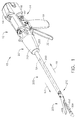
- FIGS. 1-6 depict a motor-driven surgical cutting and fastening instrument 10 that may or may not be reused.
- the instrument 10 includes a housing 12 that comprises a handle assembly 14 that is configured to be grasped, manipulated and actuated by the clinician.
- the housing 12 is configured for operable attachment to an interchangeable shaft assembly 200 that has a surgical end effector 300 operably coupled thereto that is configured to perform one or more surgical tasks or procedures.
- an interchangeable shaft assembly 200 that has a surgical end effector 300 operably coupled thereto that is configured to perform one or more surgical tasks or procedures.
- housing also may encompass a housing or similar portion of a robotic system that houses or otherwise operably supports at least one drive system that is configured to generate and apply at least one control motion which could be used to actuate the interchangeable shaft assemblies disclosed herein and their respective equivalents.
- frame may refer to a portion of a handheld surgical instrument.
- frame also may represent a portion of a robotically controlled surgical instrument and/or a portion of the robotic system that may be used to operably control a surgical instrument.
- the interchangeable shaft assemblies disclosed herein may be employed with various robotic systems, instruments, components and methods disclosed in U.S. Patent Application Publication No. U.S. 2012/0298719 .
- the housing 12 depicted in FIGS. 1-3 is shown in connection with an interchangeable shaft assembly 200 that includes an end effector 300 that comprises a surgical cutting and fastening device that is configured to operably support a surgical staple cartridge 304 therein.
- the housing 12 may be configured for use in connection with interchangeable shaft assemblies that include end effectors that are adapted to support different sizes and types of staple cartridges, have different shaft lengths, sizes, and types, etc.
- the housing 12 also may be effectively employed with a variety of other interchangeable shaft assemblies including those assemblies that are configured to apply other motions and forms of energy such as, for example, radio frequency (RF) energy, ultrasonic energy and/or motion to end effector arrangements adapted for use in connection with various surgical applications and procedures.
- RF radio frequency
- end effectors, shaft assemblies, handles, surgical instruments, and/or surgical instrument systems can utilize any suitable fastener, or fasteners, to fasten tissue.
- a fastener cartridge comprising a plurality of fasteners removably stored therein can be removably inserted into and/or attached to the end effector of a shaft assembly.
- FIG. 1 illustrates the surgical instrument 10 with an interchangeable shaft assembly 200 operably coupled thereto.
- FIGS. 2 and 3 illustrate attachment of the interchangeable shaft assembly 200 to the housing 12 or handle assembly 14.
- the handle assembly 14 may comprise a pair of interconnectable handle housing segments 16 and 18 that may be interconnected by screws, snap features, adhesive, etc.
- the handle housing segments 16, 18 cooperate to form a pistol grip portion 19 that can be gripped and manipulated by the clinician.
- the handle assembly 14 operably supports a plurality of drive systems therein that are configured to generate and apply various control motions to corresponding portions of the interchangeable shaft assembly that is operably attached thereto.
- the handle assembly 14 may further include a frame 20 that operably supports a plurality of drive systems.
- the frame 20 can operably support a "first" or closure drive system, generally designated as 30, which may be employed to apply closing and opening motions to the interchangeable shaft assembly 200 that is operably attached or coupled thereto.
- the closure drive system 30 may include an actuator in the form of a closure trigger 32 that is pivotally supported by the frame 20. More specifically, as illustrated in FIG. 4 , the closure trigger 32 is pivotally coupled to the housing 14 by a pin 33.
- the closure drive system 30 further includes a closure linkage assembly 34 that is pivotally coupled to the closure trigger 32.
- the closure linkage assembly 34 may include a first closure link 36 and a second closure link 38 that are pivotally coupled to the closure trigger 32 by a pin 35.
- the second closure link 38 also may be referred to herein as an "attachment member” and include a transverse attachment pin 37.
- the first closure link 36 may have a locking wall or end 39 thereon that is configured to cooperate with a closure release assembly 60 that is pivotally coupled to the frame 20.
- the closure release assembly 60 may comprise a release button assembly 62 that has a distally protruding locking pawl 64 formed thereon.
- the release button assembly 62 may be pivoted in a counterclockwise direction by a release spring (not shown).
- the closure release assembly 60 serves to lock the closure trigger 32 in the fully actuated position.
- the clinician desires to unlock the closure trigger 32 to permit it to be biased to the unactuated position, the clinician simply pivots the closure release button assembly 62 such that the locking pawl 64 is moved out of engagement with the locking wall 39 on the first closure link 36.
- the closure trigger 32 may pivot back to the unactuated position.
- Other closure trigger locking and release arrangements also may be employed.
- FIGS. 13-15 illustrate the closure trigger 32 in its unactuated position which is associated with an open, or unclamped, configuration of the shaft assembly 200 in which tissue can be positioned between the jaws of the shaft assembly 200.
- FIGS. 16-18 illustrate the closure trigger 32 in its actuated position which is associated with a closed, or clamped, configuration of the shaft assembly 200 in which tissue is clamped between the jaws of the shaft assembly 200.
- FIGS. 14 and 17 the reader will appreciate that, when the closure trigger 32 is moved from its unactuated position ( FIG. 14 ) to its actuated position ( FIG. 17 ), the closure release button 62 is pivoted between a first position ( FIG. 14 ) and a second position ( FIG. 17 ).
- the rotation of the closure release button 62 can be referred to as being an upward rotation; however, at least a portion of the closure release button 62 is being rotated toward the circuit board 100.
- the closure release button 62 can include an arm 61 extending therefrom and a magnetic element 63, such as a permanent magnet, for example, mounted to the arm 61.
- a magnetic element 63 such as a permanent magnet, for example, mounted to the arm 61.
- the circuit board 100 can include at least one sensor configured to detect the movement of the magnetic element 63.
- a magnetic field sensor 65 for example, can be mounted to the bottom surface of the circuit board 100.
- the magnetic field sensor 65 can be configured to detect changes in a magnetic field surrounding the magnetic field sensor 65 caused by the movement of the magnetic element 63.
- the magnetic field sensor 65 can be in signal communication with a microcontroller 1500 ( FIG. 19 ), for example, which can determine whether the closure release button 62 is in its first position, which is associated with the unactuated position of the closure trigger 32 and the open configuration of the end effector, its second position, which is associated with the actuated position of the closure trigger 32 and the closed configuration of the end effector, and/or any position between the first position and the second position.
- a magnetic field sensor may be a Hall effect sensor, search coil, fluxgate, optically pumped, nuclear precession, SQUID, Hall-effect, anisotropic magnetoresistance, giant magnetoresistance, magnetic tunnel junctions, giant magneto impedance, magnetostrictive/piezoelectric composites, magnetodiode, magnetotransistor, fiber optic, magnetooptic, and micro electromechanical systems-based magnetic sensors, among others.
- the handle assembly 14 and the frame 20 may operably support another drive system referred to herein as a firing drive system 80 that is configured to apply firing motions to corresponding portions of the interchangeable shaft assembly attached thereto.
- the firing drive system may 80 also be referred to herein as a "second drive system”.
- the firing drive system 80 may employ an electric motor 82, located in the pistol grip portion 19 of the handle assembly 14.
- the motor 82 may be a DC brushed driving motor having a maximum rotation of, approximately, 25,000 RPM, for example.
- the motor 82 may include a brushless motor, a cordless motor, a synchronous motor, a stepper motor, or any other suitable electric motor.
- the motor 82 may be powered by a power source 90 that in one form may comprise a removable power pack 92.
- the power pack 92 may comprise a proximal housing portion 94 that is configured for attachment to a distal housing portion 96.
- the proximal housing portion 94 and the distal housing portion 96 are configured to operably support a plurality of batteries 98 therein.
- Batteries 98 may each comprise, for example, a Lithium Ion ("LI”) or other suitable battery.
- the distal housing portion 96 is configured for removable operable attachment to a control circuit board assembly 100 which is also operably coupled to the motor 82.
- a number of batteries 98 may be connected in series may be used as the power source for the surgical instrument 10.
- the power source 90 may be replaceable and/or rechargeable.
- the electric motor 82 can include a rotatable shaft (not shown) that operably interfaces with a gear reducer assembly 84 that is mounted in meshing engagement with a with a set, or rack, of drive teeth 122 on a longitudinally-movable drive member 120.
- a voltage polarity provided by the power source 90 can operate the electric motor 82 in a clockwise direction wherein the voltage polarity applied to the electric motor by the battery can be reversed in order to operate the electric motor 82 in a counter-clockwise direction.
- the drive member 120 will be axially driven in the distal direction "DD".
- the handle assembly 14 can include a switch which can be configured to reverse the polarity applied to the electric motor 82 by the power source 90. As with the other forms described herein, the handle assembly 14 can also include a sensor that is configured to detect the position of the drive member 120 and/or the direction in which the drive member 120 is being moved.
- Actuation of the motor 82 can be controlled by a firing trigger 130 that is pivotally supported on the handle assembly 14.
- the firing trigger 130 may be pivoted between an unactuated position and an actuated position.
- the firing trigger 130 may be biased into the unactuated position by a spring 132 or other biasing arrangement such that when the clinician releases the firing trigger 130, it may be pivoted or otherwise returned to the unactuated position by the spring 132 or biasing arrangement.
- the firing trigger 130 can be positioned "outboard" of the closure trigger 32 as was discussed above.
- a firing trigger safety button 134 may be pivotally mounted to the closure trigger 32 by pin 35.
- the safety button 134 may be positioned between the firing trigger 130 and the closure trigger 32 and have a pivot arm 136 protruding therefrom. See FIG. 4 .
- the safety button 134 When the closure trigger 32 is in the unactuated position, the safety button 134 is contained in the handle assembly 14 where the clinician cannot readily access it and move it between a safety position preventing actuation of the firing trigger 130 and a firing position wherein the firing trigger 130 may be fired. As the clinician depresses the closure trigger 32, the safety button 134 and the firing trigger 130 pivot down wherein they can then be manipulated by the clinician.
- the handle assembly 14 can include a closure trigger 32 and a firing trigger 130.
- the firing trigger 130 can be pivotably mounted to the closure trigger 32.
- the closure trigger 32 can include an arm 31 extending therefrom and the firing trigger 130 can be pivotably mounted to the arm 31 about a pivot pin 33.
- the closure trigger 32 is moved from its unactuated position ( FIG. 14 ) to its actuated position ( FIG. 17 )
- the firing trigger 130 can descend downwardly, as outlined above.
- the firing trigger 130 can be depressed to operate the motor of the surgical instrument firing system.
- the handle assembly 14 can include a tracking system, such as system 800, for example, configured to determine the position of the closure trigger 32 and/or the position of the firing trigger 130.
- the tracking system 800 can include a magnetic element, such as permanent magnet 802, for example, which is mounted to an arm 801 extending from the firing trigger 130.
- the tracking system 800 can comprise one or more sensors, such as a first magnetic field sensor 803 and a second magnetic field sensor 804, for example, which can be configured to track the position of the magnet 802.
- the magnet 802 can move between a first position adjacent the first magnetic field sensor 803 and a second position adjacent the second magnetic field sensor 804.
- the magnet 802 can move relative to the second magnetic field sensor 804.
- the sensors 803 and 804 can track the movement of the magnet 802 and can be in signal communication with a microcontroller on the circuit board 100. With data from the first sensor 803 and/or the second sensor 804, the microcontroller can determine the position of the magnet 802 along a predefined path and, based on that position, the microcontroller can determine whether the closure trigger 32 is in its unactuated position, its actuated position, or a position therebetween.
- the microcontroller can determine the position of the magnet 802 along a predefined path and, based on that position, the microcontroller can determine whether the firing trigger 130 is in its unfired position, its fully fired position, or a position therebetween.
- the longitudinally movable drive member 120 has a rack of teeth 122 formed thereon for meshing engagement with a corresponding drive gear 86 of the gear reducer assembly 84.
- At least one form also includes a manually-actuatable "bailout” assembly 140 that is configured to enable the clinician to manually retract the longitudinally movable drive member 120 should the motor 82 become disabled.
- the bailout assembly 140 may include a lever or bailout handle assembly 142 that is configured to be manually pivoted into ratcheting engagement with teeth 124 also provided in the drive member 120.
- the clinician can manually retract the drive member 120 by using the bailout handle assembly 142 to ratchet the drive member 120 in the proximal direction "PD".
- U.S. Patent No. 8,608,045 discloses bailout arrangements and other components, arrangements and systems that also may be employed with the various instruments disclosed herein.
- the interchangeable shaft assembly 200 includes a surgical end effector 300 that comprises an elongated channel 302 that is configured to operably support a staple cartridge 304 therein.
- the end effector 300 may further include an anvil 306 that is pivotally supported relative to the elongated channel 302.
- the interchangeable shaft assembly 200 may further include an articulation joint 270 and an articulation lock 350 ( FIG. 8 ) which can be configured to releasably hold the end effector 300 in a desired position relative to a shaft axis SA-SA. Details regarding the construction and operation of the end effector 300, the articulation joint 270 and the articulation lock 350 are set forth in U.S. Patent Application Publication No. 2014/0263541 .
- the interchangeable shaft assembly 200 can further include a proximal housing or nozzle 201 comprised of nozzle portions 202 and 203.
- the interchangeable shaft assembly 200 can further include a closure tube 260 which can be utilized to close and/or open the anvil 306 of the end effector 300.
- the shaft assembly 200 can include a spine 210 which can be configured to fixably support a shaft frame portion 212 of the articulation lock 350. See FIG. 8 .
- the spine 210 can be configured to, one, slidably support a firing member 220 therein and, two, slidably support the closure tube 260 which extends around the spine 210.
- the spine 210 can also be configured to slidably support a proximal articulation driver 230.
- the articulation driver 230 has a distal end 231 that is configured to operably engage the articulation lock 350.
- the articulation lock 350 interfaces with an articulation frame 352 that is adapted to operably engage a drive pin (not shown) on the end effector frame (not shown).
- a drive pin not shown
- further details regarding the operation of the articulation lock 350 and the articulation frame may be found in U.S. Patent Application Serial No. 13/803,086 , now U.S. Patent Application Publication No. 2014/0263541 .
- the spine 210 can comprise a proximal end 211 which is rotatably supported in a chassis 240.
- the proximal end 211 of the spine 210 has a thread 214 formed thereon for threaded attachment to a spine bearing 216 configured to be supported within the chassis 240. See FIG. 7 .
- Such an arrangement facilitates rotatable attachment of the spine 210 to the chassis 240 such that the spine 210 may be selectively rotated about a shaft axis SA-SA relative to the chassis 240.
- the interchangeable shaft assembly 200 includes a closure shuttle 250 that is slidably supported within the chassis 240 such that it may be axially moved relative thereto.
- the closure shuttle 250 includes a pair ofproximally-protruding hooks 252 that are configured for attachment to the attachment pin 37 that is attached to the second closure link 38 as will be discussed in further detail below.
- a proximal end 261 of the closure tube 260 is coupled to the closure shuttle 250 for relative rotation thereto.
- a U shaped connector 263 is inserted into an annular slot 262 in the proximal end 261 of the closure tube 260 and is retained within vertical slots 253 in the closure shuttle 250. See FIG. 7 .
- closure tube 260 serves to attach the closure tube 260 to the closure shuttle 250 for axial travel therewith while enabling the closure tube 260 to rotate relative to the closure shuttle 250 about the shaft axis SA-SA.
- a closure spring 268 is journaled on the closure tube 260 and serves to bias the closure tube 260 in the proximal direction "PD" which can serve to pivot the closure trigger into the unactuated position when the shaft assembly is operably coupled to the handle assembly 14.
- the interchangeable shaft assembly 200 may further include an articulation joint 270.
- the articulation joint 270 includes a double pivot closure sleeve assembly 271.
- the double pivot closure sleeve assembly 271 includes an end effector closure sleeve assembly 272 having upper and lower distally projecting tangs 273, 274.
- An end effector closure sleeve assembly 272 includes a horseshoe aperture 275 and a tab 276 for engaging an opening tab on the anvil 306 in the various manners described in U.S. Patent Application Publication No. 2014/0263541 .
- An upper double pivot link 277 includes upwardly projecting distal and proximal pivot pins that engage respectively an upper distal pin hole in the upper proximally projecting tang 273 and an upper proximal pin hole in an upper distally projecting tang 264 on the closure tube 260.
- a lower double pivot link 278 includes upwardly projecting distal and proximal pivot pins that engage respectively a lower distal pin hole in the lower proximally projecting tang 274 and a lower proximal pin hole in the lower distally projecting tang 265. See also FIG. 8 .
- the closure tube 260 is translated distally (direction "DD") to close the anvil 306, for example, in response to the actuation of the closure trigger 32.
- the anvil 306 is closed by distally translating the closure tube 260 and thus the shaft closure sleeve assembly 272, causing it to strike a proximal surface on the anvil 360 in the manner described in the aforementioned reference U.S. Patent Application Serial No. 13/803,086 , now U.S. Patent Application Publication No. 2014/0263541 .
- the anvil 306 is opened by proximally translating the closure tube 260 and the shaft closure sleeve assembly 272, causing tab 276 and the horseshoe aperture 275 to contact and push against the anvil tab to lift the anvil 306.
- the shaft closure tube 260 is moved to its proximal position.
- the surgical instrument 10 may further include an articulation lock 350 of the types and construction described in further detail in U.S. Patent Application Serial No. 13/803,086 , now U.S. Patent Application Publication No. 2014/0263541 , which can be configured and operated to selectively lock the end effector 300 in position.
- an articulation lock 350 of the types and construction described in further detail in U.S. Patent Application Serial No. 13/803,086 , now U.S. Patent Application Publication No. 2014/0263541 , which can be configured and operated to selectively lock the end effector 300 in position.
- Such arrangement enables the end effector 300 to be rotated, or articulated, relative to the shaft closure tube 260 when the articulation lock 350 is in its unlocked state. In such an unlocked state, the end effector 300 can be positioned and pushed against soft tissue and/or bone, for example, surrounding the surgical site within the patient in order to cause the end effector 300 to articulate relative to the closure tube 260.
- the end effector 300
- the interchangeable shaft assembly 200 further includes a firing member 220 that is supported for axial travel within the shaft spine 210.
- the firing member 220 includes an intermediate firing shaft portion 222 that is configured for attachment to a distal cutting portion or knife bar 280.
- the firing member 220 also may be referred to herein as a "second shaft” and/or a "second shaft assembly”.
- the intermediate firing shaft portion 222 may include a longitudinal slot 223 in the distal end thereof which can be configured to receive a tab 284 on the proximal end 282 of the distal knife bar 280.
- the longitudinal slot 223 and the proximal end 282 can be sized and configured to permit relative movement therebetween and can comprise a slip joint 286.
- the slip joint 286 can permit the intermediate firing shaft portion 222 of the firing drive 220 to be moved to articulate the end effector 300 without moving, or at least substantially moving, the knife bar 280.
- the intermediate firing shaft portion 222 can be advanced distally until a proximal sidewall of the longitudinal slot 223 comes into contact with the tab 284 in order to advance the knife bar 280 and fire the staple cartridge positioned within the channel 302
- the shaft spine 210 has an elongate opening or window 213 therein to facilitate assembly and insertion of the intermediate firing shaft portion 222 into the shaft frame 210.
- a top frame segment 215 may be engaged with the shaft frame 212 to enclose the intermediate firing shaft portion 222 and knife bar 280 therein. Further description of the operation of the firing member 220 may be found in U.S. Patent Application Serial No. 13/803,086 , now U.S. Patent Application Publication No. 2014/0263541 .
- the shaft assembly 200 can include a clutch assembly 400 which can be configured to selectively and releasably couple the articulation driver 230 to the firing member 220.
- the clutch assembly 400 includes a lock collar, or sleeve 402, positioned around the firing member 220 wherein the lock sleeve 402 can be rotated between an engaged position in which the lock sleeve 402 couples the articulation driver 360 to the firing member 220 and a disengaged position in which the articulation driver 360 is not operably coupled to the firing member 200.
- lock sleeve 402 When lock sleeve 402 is in its engaged position, distal movement of the firing member 220 can move the articulation driver 360 distally and, correspondingly, proximal movement of the firing member 220 can move the articulation driver 230 proximally.
- lock sleeve 402 When lock sleeve 402 is in its disengaged position, movement of the firing member 220 is not transmitted to the articulation driver 230 and, as a result, the firing member 220 can move independently of the articulation driver 230.
- the articulation driver 230 can be held in position by the articulation lock 350 when the articulation driver 230 is not being moved in the proximal or distal directions by the firing member 220.
- the lock sleeve 402 can comprise a cylindrical, or an at least substantially cylindrical, body including a longitudinal aperture 403 defined therein configured to receive the firing member 220.
- the lock sleeve 402 can comprise diametrically-opposed, inwardly-facing lock protrusions 404 and an outwardly-facing lock member 406.
- the lock protrusions 404 can be configured to be selectively engaged with the firing member 220.
- the lock protrusions 404 are positioned within a drive notch 224 defined in the firing member 220 such that a distal pushing force and/or a proximal pulling force can be transmitted from the firing member 220 to the lock sleeve 402.
- the second lock member 406 is received within a drive notch 232 defined in the articulation driver 230 such that the distal pushing force and/or the proximal pulling force applied to the lock sleeve 402 can be transmitted to the articulation driver 230.
- the firing member 220, the lock sleeve 402, and the articulation driver 230 will move together when the lock sleeve 402 is in its engaged position.
- the lock protrusions 404 may not be positioned within the drive notch 224 of the firing member 220 and, as a result, a distal pushing force and/or a proximal pulling force may not be transmitted from the firing member 220 to the lock sleeve 402.
- the distal pushing force and/or the proximal pulling force may not be transmitted to the articulation driver 230.
- the firing member 220 can be slid proximally and/or distally relative to the lock sleeve 402 and the proximal articulation driver 230.
- the shaft assembly 200 further includes a switch drum 500 that is rotatably received on the closure tube 260.
- the switch drum 500 comprises a hollow shaft segment 502 that has a shaft boss 504 formed thereon for receive an outwardly protruding actuation pin 410 therein.
- the actuation pin 410 extends through a slot 267 into a longitudinal slot 408 provided in the lock sleeve 402 to facilitate axial movement of the lock sleeve 402 when it is engaged with the articulation driver 230.
- a rotary torsion spring 420 is configured to engage the boss 504 on the switch drum 500 and a portion of the nozzle housing 203 as shown in FIG.
- the switch drum 500 can further comprise at least partially circumferential openings 506 defined therein which, referring to FIGS. 5 and 6 , can be configured to receive circumferential mounts 204, 205 extending from the nozzle halves 202, 203 and permit relative rotation, but not translation, between the switch drum 500 and the proximal nozzle 201. As shown in those Figures, the mounts 204 and 205 also extend through openings 266 in the closure tube 260 to be seated in recesses 209 in the shaft spine 210.
- the nozzle 201 may be employed to operably engage and disengage the articulation drive system with the firing drive system in the various manners described in further detail in U.S. Patent Application Serial No. 13/803,086 , now U.S. Patent Application Publication No. 2014/0263541 .
- the shaft assembly 200 can comprise a slip ring assembly 600 which can be configured to conduct electrical power to and/or from the end effector 300 and/or communicate signals to and/or from the end effector 300, for example.
- the slip ring assembly 600 can comprise a proximal connector flange 604 mounted to a chassis flange 242 extending from the chassis 240 and a distal connector flange 601 positioned within a slot defined in the shaft housings 202, 203.
- the proximal connector flange 604 can comprise a first face and the distal connector flange 601 can comprise a second face which is positioned adjacent to and movable relative to the first face.
- the distal connector flange 601 can rotate relative to the proximal connector flange 604 about the shaft axis SA-SA.
- the proximal connector flange 604 can comprise a plurality of concentric, or at least substantially concentric, conductors 602 defined in the first face thereof.
- a connector 607 can be mounted on the proximal side of the connector flange 601 and may have a plurality of contacts (not shown) wherein each contact corresponds to and is in electrical contact with one of the conductors 602. Such an arrangement permits relative rotation between the proximal connector flange 604 and the distal connector flange 601 while maintaining electrical contact therebetween.
- the proximal connector flange 604 can include an electrical connector 606 which can place the conductors 602 in signal communication with a shaft circuit board 610 mounted to the shaft chassis 240, for example.
- a wiring harness comprising a plurality of conductors can extend between the electrical connector 606 and the shaft circuit board 610.
- the electrical connector 606 may extend proximally through a connector opening 243 defined in the chassis mounting flange 242. See FIG. 7 . Further details regarding slip ring assembly 600 may be found in U.S. Patent Application Publication No. 2014/0263541 .
- the shaft assembly 200 can include a proximal portion which is fixably mounted to the handle assembly 14 and a distal portion which is rotatable about a longitudinal axis.
- the rotatable distal shaft portion can be rotated relative to the proximal portion about the slip ring assembly 600, as discussed above.
- the distal connector flange 601 of the slip ring assembly 600 can be positioned within the rotatable distal shaft portion.
- the switch drum 500 can also be positioned within the rotatable distal shaft portion. When the rotatable distal shaft portion is rotated, the distal connector flange 601 and the switch drum 500 can be rotated synchronously with one another.
- the switch drum 500 can be rotated between a first position and a second position relative to the distal connector flange 601.
- the articulation drive system When the switch drum 500 is in its first position, the articulation drive system may be operably disengaged from the firing drive system and, thus, the operation of the firing drive system may not articulate the end effector 300 of the shaft assembly 200.
- the switch drum 500 When the switch drum 500 is in its second position, the articulation drive system may be operably engaged with the firing drive system and, thus, the operation of the firing drive system may articulate the end effector 300 of the shaft assembly 200.
- the switch drum 500 When the switch drum 500 is moved between its first position and its second position, the switch drum 500 is moved relative to distal connector flange 601.
- the shaft assembly 200 can comprise at least one sensor configured to detect the position of the switch drum 500.
- the distal connector flange 601 can comprise a magnetic field sensor 605, for example, and the switch drum 500 can comprise a magnetic element, such as permanent magnet 505, for example.
- the magnetic field sensor 605 can be configured to detect the position of the permanent magnet 505.
- the switch drum 500 is rotated between its first position and its second position, the permanent magnet 505 can move relative to the magnetic field sensor 605.
- magnetic field sensor 605 can detect changes in a magnetic field created when the permanent magnet 505 is moved.
- the magnetic field sensor 605 can be in signal communication with the shaft circuit board 610 and/or the handle circuit board 100, for example. Based on the signal from the magnetic field sensor 605, a microcontroller on the shaft circuit board 610 and/or the handle circuit board 100 can determine whether the articulation drive system is engaged with or disengaged from the firing drive system.
- the chassis 240 includes at least one, and preferably two, tapered attachment portions 244 formed thereon that are adapted to be received within corresponding dovetail slots 702 formed within a distal attachment flange portion 700 of the frame 20.
- Each dovetail slot 702 may be tapered or, stated another way, be somewhat V-shaped to seatingly receive the attachment portions 244 therein.
- a shaft attachment lug 226 is formed on the proximal end of the intermediate firing shaft 222.
- the shaft attachment lug 226 is received in a firing shaft attachment cradle 126 formed in the distal end 125 of the longitudinal drive member 120 as shown in FIGS. 3 and 6 , for example.
- the latch system 710 includes a lock member or lock yoke 712 that is movably coupled to the chassis 240.
- the lock yoke 712 has a U-shape with two spaced downwardly extending legs 714.
- the legs 714 each have a pivot lug 715 formed thereon that are adapted to be received in corresponding holes 245 formed in the chassis 240.
- Such arrangement facilitates pivotal attachment of the lock yoke 712 to the chassis 240.
- the lock yoke 712 may include two proximally protruding lock lugs 716 that are configured for releasable engagement with corresponding lock detents or grooves 704 in the distal attachment flange 700 of the frame 20. See FIG. 3 .
- the lock yoke 712 is biased in the proximal direction by spring or biasing member (not shown). Actuation of the lock yoke 712 may be accomplished by a latch button 722 that is slidably mounted on a latch actuator assembly 720 that is mounted to the chassis 240.
- the latch button 722 may be biased in a proximal direction relative to the lock yoke 712.
- the lock yoke 712 may be moved to an unlocked position by biasing the latch button the in distal direction which also causes the lock yoke 712 to pivot out of retaining engagement with the distal attachment flange 700 of the frame 20.
- the lock lugs 716 are retainingly seated within the corresponding lock detents or grooves 704 in the distal attachment flange 700.
- an interchangeable shaft assembly that includes an end effector of the type described herein that is adapted to cut and fasten tissue, as well as other types of end effectors
- the clinician may actuate the closure trigger 32 to grasp and manipulate the target tissue into a desired position. Once the target tissue is positioned within the end effector 300 in a desired orientation, the clinician may then fully actuate the closure trigger 32 to close the anvil 306 and clamp the target tissue in position for cutting and stapling. In that instance, the first drive system 30 has been fully actuated.
- One form of the latch system 710 is configured to prevent such inadvertent detachment.
- the lock yoke 712 includes at least one and preferably two lock hooks 718 that are adapted to contact corresponding lock lug portions 256 that are formed on the closure shuttle 250.
- the lock yoke 712 may be pivoted in a distal direction to unlock the interchangeable shaft assembly 200 from the housing 12.
- the lock hooks 718 do not contact the lock lug portions 256 on the closure shuttle 250.
- the lock yoke 712 is prevented from being pivoted to an unlocked position. See FIGS. 16-18 .
- the clinician were to attempt to pivot the lock yoke 712 to an unlocked position or, for example, the lock yoke 712 was in advertently bumped or contacted in a manner that might otherwise cause it to pivot distally, the lock hooks 718 on the lock yoke 712 will contact the lock lug portions 256 on the closure shuttle 250 and prevent movement of the lock yoke 712 to an unlocked position.
- the clinician may position the chassis 240 of the interchangeable shaft assembly 200 above or adjacent to the distal attachment flange 700 of the frame 20 such that the tapered attachment portions 244 formed on the chassis 240 are aligned with the dovetail slots 702 in the frame 20.
- the clinician may then move the shaft assembly 200 along an installation axis IA that is perpendicular to the shaft axis SA-SA to seat the attachment portions 244 in "operable engagement" with the corresponding dovetail receiving slots 702.
- the shaft attachment lug 226 on the intermediate firing shaft 222 will also be seated in the cradle 126 in the longitudinally movable drive member 120 and the portions of pin 37 on the second closure link 38 will be seated in the corresponding hooks 252 in the closure yoke 250.
- operble engagement in the context of two components means that the two components are sufficiently engaged with each other so that upon application of an actuation motion thereto, the components may carry out their intended action, function and/or procedure.
- a first system can comprise a frame system which couples and/or aligns the frame or spine of the shaft assembly 200 with the frame 20 of the handle assembly 14.
- Another system can comprise a closure drive system 30 which can operably connect the closure trigger 32 of the handle assembly 14 and the closure tube 260 and the anvil 306 of the shaft assembly 200.
- the closure tube attachment yoke 250 of the shaft assembly 200 can be engaged with the pin 37 on the second closure link 38.
- Another system can comprise the firing drive system 80 which can operably connect the firing trigger 130 of the handle assembly 14 with the intermediate firing shaft 222 of the shaft assembly 200.
- the shaft attachment lug 226 can be operably connected with the cradle 126 of the longitudinal drive member 120.
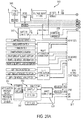
- Another system can comprise an electrical system which can signal to a controller in the handle assembly 14, such as microcontroller, for example, that a shaft assembly, such as shaft assembly 200, for example, has been operably engaged with the handle assembly 14 and/or, two, conduct power and/or communication signals between the shaft assembly 200 and the handle assembly 14.
- the shaft assembly 200 can include an electrical connector 1410 that is operably mounted to the shaft circuit board 610.
- the electrical connector 1410 is configured for mating engagement with a corresponding electrical connector 1400 on the handle control board 100. Further details regaining the circuitry and control systems may be found in U.S. Patent Application Publication No. 2014/0263541 .
- the fifth system may consist of the latching system for releasably locking the shaft assembly 200 to the handle assembly 14.
- the handle assembly 14 can include an electrical connector 1400 comprising a plurality of electrical contacts.
- the electrical connector 1400 can comprise a first contact 1401 a, a second contact 1401 b, a third contact 1401 c, a fourth contact 1401 d, a fifth contact 1401 e, and a sixth contact 1401 f, for example. While the illustrated example utilizes six contacts, other examples are envisioned which may utilize more than six contacts or less than six contacts.
- the first contact 1401 a can be in electrical communication with a transistor 1408, contacts 1401b-1401e can be in electrical communication with a microcontroller 1500, and the sixth contact 1401f can be in electrical communication with a ground.
- one or more of the electrical contacts 1401b-1401e may be in electrical communication with one or more output channels of the microcontroller 1500 and can be energized, or have a voltage potential applied thereto, when the handle assembly 14 is in a powered state.
- one or more of the electrical contacts 1401b-1401e may be in electrical communication with one or more input channels of the microcontroller 1500 and, when the handle assembly 14 is in a powered state, the microcontroller 1500 can be configured to detect when a voltage potential is applied to such electrical contacts.
- the electrical contacts 1401a-1401f may not communicate with each other.
- the electrical contacts 1401a-1401f of the electrical connector 1400 may be exposed and, in some circumstances, one or more of the contacts 1401a-1401f may be accidentally placed in electrical communication with each other.
- Such circumstances can arise when one or more of the contacts 1401a-1401f come into contact with an electrically conductive material, for example.
- the microcontroller 1500 can receive an erroneous input and/or the shaft assembly 200 can receive an erroneous output, for example.
- the handle assembly 14 may be unpowered when a shaft assembly, such as shaft assembly 200, for example, is not attached to the handle assembly 14.
- the handle assembly 14 can be powered when a shaft assembly, such as shaft assembly 200, for example, is not attached thereto.
- the microcontroller 1500 can be configured to ignore inputs, or voltage potentials, applied to the contacts in electrical communication with the microcontroller 1500, i.e., contacts 1401b-1401e, for example, until a shaft assembly is attached to the handle assembly 14.
- the handle assembly 14 may be in a powered-down state.
- the electrical connector 1400 may be in a powered-down state as voltage potentials applied to the electrical contacts 1401b-1401e may not affect the operation ofthe handle assembly 14.
- contacts 1401b-1401e may be in a powered-down state
- the electrical contacts 1401 a and 1401 f which are not in electrical communication with the microcontroller 1500, may or may not be in a powered-down state.
- sixth contact 1401f may remain in electrical communication with a ground regardless of whether the handle assembly 14 is in a powered-up or a powered-down state.
- the transistor 1408, and/or any other suitable arrangement of transistors, such as transistor 1410, for example, and/or switches may be configured to control the supply of power from a power source 1404, such as a battery 90 within the handle assembly 14, for example, to the first electrical contact 1401a regardless of whether the handle assembly 14 is in a powered-up or a powered-down state.
- a power source 1404 such as a battery 90 within the handle assembly 14, for example
- the shaft assembly 200 for example, can be configured to change the state ofthe transistor 1408 when the shaft assembly 200 is engaged with the handle assembly 14.
- a magnetic field sensor 1402 can be configured to switch the state of transistor 1410 which, as a result, can switch the state of transistor 1408 and ultimately supply power from power source 1404 to first contact 1401 a. In this way, both the power circuits and the signal circuits to the connector 1400 can be powered down when a shaft assembly is not installed to the handle assembly 14 and powered up when a shaft assembly is installed to the handle assembly 14.
- the handle assembly 14 can include the magnetic field sensor 1402, for example, which can be configured to detect a detectable element, such as a magnetic element 1407 ( FIG. 3 ), for example, on a shaft assembly, such as shaft assembly 200, for example, when the shaft assembly is coupled to the handle assembly 14.
- the magnetic field sensor 1402 can be powered by a power source 1406, such as a battery, for example, which can, in effect, amplify the detection signal of the magnetic field sensor 1402 and communicate with an input channel of the microcontroller 1500 via the circuit illustrated in FIG. 19 .
- the microcontroller 1500 can enter into its normal, or powered-up, operating state. In such an operating state, the microcontroller 1500 will evaluate the signals transmitted to one or more of the contacts 1401b-1401e from the shaft assembly and/or transmit signals to the shaft assembly through one or more of the contacts 1401b-1401e in normal use thereof. In various circumstances, the shaft assembly 200 may have to be fully seated before the magnetic field sensor 1402 can detect the magnetic element 1407.
- both the power circuits and the signal circuits to the connector 1400 can be powered down when a shaft assembly is not installed to the handle assembly 14 and powered up when a shaft assembly is installed to the handle assembly 14.
- any suitable magnetic field sensor may be employed to detect whether a shaft assembly has been assembled to the handle assembly 14, for example.
- the technologies used for magnetic field sensing include Hall effect sensor, search coil, fluxgate, optically pumped, nuclear precession, SQUID, Hall-effect, anisotropic magnetoresistance, giant magnetoresistance, magnetic tunnel junctions, giant magnetoimpedance, magnetostrictive/piezoelectric composites, magnetodiode, magnetotransistor, fiber optic, magnetooptic, and microelectromechanical systems-based magnetic sensors, among others.
- the microcontroller 1500 may generally comprise a microprocessor ("processor") and one or more memory units operationally coupled to the processor. By executing instruction code stored in the memory, the processor may control various components of the surgical instrument, such as the motor, various drive systems, and/or a user display, for example.
- the microcontroller 1500 may be implemented using integrated and/or discrete hardware elements, software elements, and/or a combination of both.
- Examples of integrated hardware elements may include processors, microprocessors, microcontrollers, integrated circuits, application specific integrated circuits (ASIC), programmable logic devices (PLD), digital signal processors (DSP), field programmable gate arrays (FPGA), logic gates, registers, semiconductor devices, chips, microchips, chip sets, microcontrollers, system-on-chip (SoC), and/or system-in-package (SIP).
- Examples of discrete hardware elements may include circuits and/or circuit elements such as logic gates, field effect transistors, bipolar transistors, resistors, capacitors, inductors, and/or relays.
- the microcontroller 1500 may include a hybrid circuit comprising discrete and integrated circuit elements or components on one or more substrates, for example.
- the microcontroller 1500 may be an LM 4F230H5QR, available from Texas Instruments, for example.
- the Texas Instruments LM4F230H5QR is an ARM Cortex-M4F Processor Core comprising on-chip memory of 256 KB single-cycle flash memory, or other non-volatile memory, up to 40 MHz, a prefetch buffer to improve performance above 40 MHz, a 32 KB single-cycle serial random access memory (SRAM), internal read-only memory (ROM) loaded with StellarisWare® software, 2KB electrically erasable programmable read-only memory (EEPROM), one or more pulse width modulation (PWM) modules, one or more quadrature encoder inputs (QEI) analog, one or more 12-bit Analog-to-Digital Converters (ADC) with 12 analog input channels, among other features that are readily available.
- Other microcontrollers may be readily substituted for use with the present disclosure. Accordingly, the present disclosure should not be limited in this context
- the handle assembly 14 and/or the shaft assembly 200 can include systems and configurations configured to prevent, or at least reduce the possibility of, the contacts of the handle electrical connector 1400 and/or the contacts of the shaft electrical connector 1410 from becoming shorted out when the shaft assembly 200 is not assembled, or completely assembled, to the handle assembly 14.
- the handle electrical connector 1400 can be at least partially recessed within a cavity 1409 defined in the handle frame 20.
- the six contacts 1401a-1401f of the electrical connector 1400 can be completely recessed within the cavity 1409. Such arrangements can reduce the possibility of an object accidentally contacting one or more of the contacts 1401a-1401f.
- the shaft electrical connector 1410 can be positioned within a recess defined in the shaft chassis 240 which can reduce the possibility of an object accidentally contacting one or more of the contacts 1411a-1411f of the shaft electrical connector 1410.
- the shaft contacts 1411a-1411f can comprise male contacts.
- each shaft contact 1411a-1411f can comprise a flexible projection extending therefrom which can be configured to engage a corresponding handle contact 1401a-1401f, for example.
- the handle contacts 1401a-1401f can comprise female contacts.
- each handle contact 1401a-1401f can comprise a flat surface, for example, against which the male shaft contacts 1401a-1401f can wipe, or slide, against and maintain an electrically conductive interface therebetween.
- the direction in which the shaft assembly 200 is assembled to the handle assembly 14 can be parallel to, or at least substantially parallel to, the handle contacts 1401a-1401f such that the shaft contacts 1411a-1411f slide against the handle contacts 1401a-1401f when the shaft assembly 200 is assembled to the handle assembly 14.
- the handle contacts 1401a-1401f can comprise male contacts and the shaft contacts 1411a-1411f can comprise female contacts.
- the handle contacts 1401a-1401f and the shaft contacts 1411a-1411f can comprise any suitable arrangement of contacts.
- the handle assembly 14 can comprise a connector guard configured to at least partially cover the handle electrical connector 1400 and/or a connector guard configured to at least partially cover the shaft electrical connector 1410.
- a connector guard can prevent, or at least reduce the possibility of, an object accidentally touching the contacts of an electrical connector when the shaft assembly is not assembled to, or only partially assembled to, the handle.
- a connector guard can be movable. For instance, the connector guard can be moved between a guarded position in which it at least partially guards a connector and an unguarded position in which it does not guard, or at least guards less of, the connector. In at least one example, a connector guard can be displaced as the shaft assembly is being assembled to the handle.
- a connector guard can comprise a door, for example.
- the door can comprise a beveled surface which, when contacted by the handle or shaft, can facilitate the displacement of the door in a certain direction.
- the connector guard can be translated and/or rotated, for example.
- a connector guard can comprise at least one film which covers the contacts of an electrical connector. When the shaft assembly is assembled to the handle, the film can become ruptured. In at least one instance, the male contacts of a connector can penetrate the film before engaging the corresponding contacts positioned underneath the film.
- the surgical instrument can include a system which can selectively power-up, or activate, the contacts of an electrical connector, such as the electrical connector 1400, for example.
- the contacts can be transitioned between an unactivated condition and an activated condition.
- the contacts can be transitioned between a monitored condition, a deactivated condition, and an activated condition.
- the microcontroller 1500 can monitor the contacts 1401a-1401f when a shaft assembly has not been assembled to the handle assembly 14 to determine whether one or more of the contacts 1401a-1401f may have been shorted.
- the microcontroller 1500 can be configured to apply a low voltage potential to each of the contacts 1401a-1401f and assess whether only a minimal resistance is present at each of the contacts.
- Such an operating state can comprise the monitored condition.
- the microcontroller 1500 can deactivate that contact, more than one contact, or, alternatively, all of the contacts.
- Such an operating state can comprise the deactivated condition. If a shaft assembly is assembled to the handle assembly 14 and it is detected by the microcontroller 1500, as discussed above, the microcontroller 1500 can increase the voltage potential to the contacts 1401a-1401f.
- Such an operating state can comprise the activated condition.
- the various shaft assemblies disclosed herein may employ sensors and various other components that require electrical communication with the controller in the housing. These shaft assemblies generally are configured to be able to rotate relative to the housing necessitating a connection that facilitates such electrical communication between two or more components that may rotate relative to each other.
- the connector arrangements must be relatively robust in nature while also being somewhat compact to fit into the shaft assembly connector portion.
- the end effector 300 may include the anvil 306 and the staple cartridge 304.
- the anvil 306 is coupled to an elongate channel 198.
- apertures 199 can be defined in the elongate channel 198 which can receive pins 152 extending from the anvil 306 and allow the anvil 306 to pivot from an open position to a closed position relative to the elongate channel 198 and staple cartridge 304.
- FIG. 20 shows a firing bar 172, configured to longitudinally translate into the end effector 300.
- the firing bar 172 may be constructed from one solid section, or in various examples, may include a laminate material comprising, for example, a stack of steel plates.
- a distally projecting end of the firing bar 172 can be attached to an E-beam 178 that can, among other things, assist in spacing the anvil 306 from a staple cartridge 304 positioned in the elongate channel 198 when the anvil 306 is in a closed position.
- the E-beam 178 can also include a sharpened cutting edge 182 which can be used to sever tissue as the E-beam 178 is advanced distally by the firing bar 172. In operation, the E-beam 178 can also actuate, or fire, the staple cartridge 304.
- the staple cartridge 304 can include a molded cartridge body 194 that holds a plurality of staples 191 resting upon staple drivers 192 within respective upwardly open staple cavities 195.
- a wedge sled 190 is driven distally by the E-beam 178, sliding upon a cartridge tray 196 that holds together the various components of the replaceable staple cartridge 304.
- the wedge sled 190 upwardly cams the staple drivers 192 to force out the staples 191 into deforming contact with the anvil 306 while a cutting surface 182 of the E-beam 178 severs clamped tissue.
- the E-beam 178 can include upper pins 180 which engage the anvil 306 during firing.
- the E-beam 178 can further include middle pins 184 and a bottom foot 186 which can engage various portions of the cartridge body 194, cartridge tray 196 and elongate channel 198.
- a slot 193 defined in the cartridge body 194 can be aligned with a slot 197 defined in the cartridge tray 196 and a slot 189 defined in the elongate channel 198.
- the E-beam 178 can slide through the aligned slots 193, 197, and 189 wherein, as indicated in FIG.
- the bottom foot 186 of the E-beam 178 can engage a groove running along the bottom surface of channel 198 along the length of slot 189, the middle pins 184 can engage the top surfaces of cartridge tray 196 along the length of longitudinal slot 197, and the upper pins 180 can engage the anvil 306.
- the E-beam 178 can space, or limit the relative movement between, the anvil 306 and the staple cartridge 304 as the firing bar 172 is moved distally to fire the staples from the staple cartridge 304 and/or incise the tissue captured between the anvil 306 and the staple cartridge 304. Thereafter, the firing bar 172 and the E-beam 178 can be retracted proximally allowing the anvil 306 to be opened to release the two stapled and severed tissue portions (not shown).
- FIGS. 21A-21B where one example of a segmented circuit 2000 comprising a plurality of circuit segments 2002a-2002g is illustrated.
- the segmented circuit 2000 comprising the plurality of circuit segments 2002a-2002g is configured to control a powered surgical instrument, such as, for example, the surgical instrument 10 illustrated in FIGS. 1-18A , without limitation.
- the plurality of circuit segments 2002a-2002g is configured to control one or more operations of the powered surgical instrument 10.
- a safety processor segment 2002a (Segment 1) comprises a safety processor 2004.
- a primary processor segment 2002b (Segment 2) comprises a primary or main processor 2006.
- the safety processor 2004 and/or the primary processor 2006 are configured to interact with one or more additional circuit segments 2002c-2002g to control operation of the powered surgical instrument 10.
- the primary processor 2006 comprises a plurality of inputs coupled to, for example, one or more circuit segments 2002c-2002g, a battery 2008, and/or a plurality of switches 2056-2070.
- the segmented circuit 2000 may be implemented by any suitable circuit, such as, for example, a printed circuit board assembly (PCBA) within the powered surgical instrument 10.
- PCBA printed circuit board assembly
- processor includes any microprocessor, microcontroller, or other basic computing device that incorporates the functions of a computer's central processing unit (CPU) on an integrated circuit or at most a few integrated circuits.
- the processor is a multipurpose, programmable device that accepts digital data as input, processes it according to instructions stored in its memory, and provides results as output. It is an example of sequential digital logic, as it has internal memory. Processors operate on numbers and symbols represented in the binary numeral system.
- the main processor 2006 may be any single core or multicore processor such as those known under the trade name ARM Cortex by Texas Instruments.
- the safety processor 2004 may be a safety microcontroller platform comprising two microcontroller-based families such as TMS570 and RM4x known under the trade name Hercules ARM Cortex R4, also by Texas Instruments. Nevertheless, other suitable substitutes for microcontrollers and safety processor may be employed, without limitation.
- the safety processor 2004 may be configured specifically for IEC 61508 and ISO 26262 safety critical applications, among others, to provide advanced integrated safety features while delivering scalable performance, connectivity, and memory options.
- the main processor 2006 may be an LM 4F230H5QR, available from Texas Instruments, for example.
- the Texas Instruments LM4F230H5QR is an ARM Cortex-M4F Processor Core comprising on-chip memory of 256 KB single-cycle flash memory, or other non-volatile memory, up to 40 MHz, a prefetch buffer to improve performance above 40 MHz, a 32 KB single-cycle SRAM, internal ROM loaded with StellarisWare® software, 2KB EEPROM, one or more PWM modules, one or more QEI analog, one or more 12-bit ADC with 12 analog input channels, among other features that are readily available for the product datasheet.
- Other processors may be readily substituted and, accordingly, the present disclosure should not be limited in this context.
- the segmented circuit 2000 comprises an acceleration segment 2002c (Segment 3).
- the acceleration segment 2002c comprises an acceleration sensor 2022.
- the acceleration sensor 2022 may comprise, for example, an accelerometer.
- the acceleration sensor 2022 is configured to detect movement or acceleration of the powered surgical instrument 10.
- input from the acceleration sensor 2022 is used, for example, to transition to and from a sleep mode, identify an orientation of the powered surgical instrument, and/or identify when the surgical instrument has been dropped.
- the acceleration segment 2002c is coupled to the safety processor 2004 and/or the primary processor 2006.
- the segmented circuit 2000 comprises a display segment 2002d (Segment 4).
- the display segment 2002d comprises a display connector (not shown) which is coupled to the primary processor 2006, one or more display driver integrated circuits (not shown) which are coupled to the display connector, and a display 2028 which is coupled to the one or more display driver integrated circuits.
- the display connector and the one or more display driver integrated circuits are shown, for example, in FIG. 4B of U.S. Patent Application Publication No. 2015/0280424 A1 .
- the display driver integrated circuits may be integrated with the display 2028 and/or may be located separately from the display 2028.
- the display 2028 may comprise any suitable display, such as, for example, an organic light-emitting diode (OLED) display, a liquid-crystal display (LCD), and/or any other suitable display.
- OLED organic light-emitting diode
- LCD liquid-crystal display
- the display segment 2002d is coupled to the safety processor 2004.
- the segmented circuit 2000 comprises a shaft segment 2002e (Segment 5).
- the shaft segment 2002e comprises one or more controls for a shaft assembly (e.g., shaft assembly 200) coupled to the surgical instrument 10 and/or one or more controls for an end effector (e.g., end effector 300) coupled to the shaft 200.
- the shaft segment 2002e comprises a shaft connector 2030 and a shaft printed circuit board assembly (PCBA) 2031.
- the shaft connector 2030 is configured to couple the shaft PCBA 2031 to the primary processor 2006.
- the shaft PCBA 2031 comprises a first articulation switch (not shown), a second articulation switch (not shown), and a shaft PCBA EEPROM (not shown).
- the shaft PCBA EEPROM comprises one or more parameters, routines, and/or programs specific to the shaft assembly 200 and/or the shaft PCBA 2031.
- the shaft PCBA 2031 may be coupled to the shaft assembly 200 and/or integral with the surgical instrument 10.
- the shaft segment 2002e comprises a second shaft EEPROM (not shown).
- the second shaft EEPROM comprises a plurality of algorithms, routines, parameters, and/or other data corresponding to one or more shaft assemblies 200 and/or end effectors 300 which may be interfaced with the powered surgical instrument 10.
- the first articulation switch, the second articulation switch, and the shaft PCBA EEPROMs are shown, for example, in FIG. 4A of U.S. Patent Application Publication No. 2015/0280424 A1 .
- the shaft segment 2002 e comprises the shaft PCBA 2031, a Hall effect sensor 2070 and the shaft connector 2025.
- the shaft PCBA 2031 comprises a low-power microprocessor 2090 with ferroelectric random access memory (FRAM) technology, a mechanical articulation switch 2092, a shaft release Hall effect switch 2094 and flash memory 2034.
- the Hall effect sensor 2070 is utilized to indicate engagement of the shaft assembly 200 and thus may be considered a shaft engaged switch.
- the segmented circuit 2000 comprises a position encoder segment 2002f (Segment 6).
- the position encoder segment 2002f comprises one or more magnetic rotary position encoders 2040a-2040b.
- the one or more magnetic rotary position encoders 2040a-2040b are configured to identify the rotational position of a motor 2048, a shaft assembly 200, and/or an end effector 300 of the surgical instrument 10.
- the magnetic rotary position encoders 2040a-2040b may be coupled to the safety processor 2004 and/or the primary processor 2006.
- the segmented circuit 2000 comprises a motor segment 2002g (Segment 7).
- the motor segment 2002g comprises a motor 2048, such as, for example, a brushed DC motor, configured to control one or more movements of the powered surgical instrument 10.
- the motor 2048 is coupled to the primary processor 2006 through a motor controller 2043, a plurality of H-bridge drivers 2042 and a plurality of H-bridge field-effect transistors (not shown).
- the H-bridge field-effect transistors (FETs) are coupled to the safety processor 2004.
- the H-bridge FETs are shown, for example, in FIG. 4B of U.S. Patent Application Publication No. 2015/0280424 A1 .
- the motor controller 2043 controls a first motor flag 2074a and a second motor flag 2074b to indicate the status and position of the motor 2048 to the primary processor 2006.
- the primary processor 2006 provides a pulse-width modulation (PWM) high signal 2076a, a PWM low signal 2076b, a direction signal 2078, a synchronize signal 2080, and a motor reset signal 2082 to the motor controller 2043 through a buffer 2084.
- a motor current sensor 2046 is coupled in series with the motor 2048 to measure the current draw of the motor 2048.
- the motor current sensor 2046 is in signal communication with the primary processor 2006 and/or the safety processor 2004.
- the motor 2048 is coupled to a motor electromagnetic interference (EMI) filter (not shown).
- the EMI filter is shown, for example, in FIG. 3B of U.S. Patent Application Publication No. 2015/0280424 A1 .
- the segmented circuit 2000 comprises a power segment 2002h (Segment 8) configured to provide a segment voltage to each of the circuit segments 1102a-1102g.
- a battery 2008 is coupled to the safety processor 2004, the primary processor 2006, and one or more of the additional circuit segments 2002c-2002g.
- the battery 2008 is coupled to the segmented circuit 2000 by a battery connector 2010 and a current sensor 2012.
- the current sensor 2012 is configured to measure the total current draw of the segmented circuit 2000.
- one or more voltage converters 2014a, 2014b, 2016 are configured to provide predetermined voltage values to one or more circuit segments 2002a-2002g.
- the segmented circuit 2000 may comprise 3.3V voltage converters 2014a-2014b and/or 5V voltage converters 2016.
- a boost converter 2018 is configured to provide a boost voltage up to a predetermined amount, such as, for example, up to 13V.
- the boost converter 2018 is configured to provide additional voltage and/or current during power intensive operations and prevent brownout or low-power conditions.
- a transistor switch (e.g., N-Channel MOSFET) 2015 is coupled to the power converters 2014B, 2016.
- the safety segment 2002a comprises a motor power interrupt 2020.
- the motor power interrupt 2020 is coupled between the power segment 2002h and the motor segment 2002g.
- a transistor switch (e.g., N-Channel MOSFET) 2057 is coupled to the motor power interrupt 2020.
- the safety segment 2002a is configured to interrupt power to the motor segment 2002g when an error or fault condition is detected by the safety processor 2004 and/or the primary processor 2006 as discussed in more detail herein.
- the circuit segments 2002a-2002g are illustrated with all components of the circuit segments 2002a-2002h located in physical proximity, one skilled in the art will recognize that a circuit segment 2002a-2002h may comprise components physically and/or electrically separate from other components of the same circuit segment 2002a-2002g. In some examples, one or more components may be shared between two or more circuit segments 2002a-2002g.
- a plurality of switches 2056-2070 are coupled to the safety processor 2004 and/or the primary processor 2006.
- the plurality of switches 2056-2070 may be configured to control one or more operations of the surgical instrument 10, control one or more operations of the segmented circuit 2000, and/or indicate a status of the surgical instrument 10.
- a bail-out door switch 2056 is configured to indicate the status of a bail-out door.
- a plurality of articulation switches such as, for example, a left side articulation left switch 2058a, a left side articulation right switch 2060a, a left side articulation center switch 2062a, a right side articulation left switch 2058b, a right side articulation right switch 2060b, and a right side articulation center switch 2062b are configured to control articulation of a shaft assembly 200 and/or an end effector 300.
- a left side reverse switch 2064a and a right side reverse switch 2064b are coupled to the primary processor 2006.
- the left side switches comprising the left side articulation left switch 2058a, the left side articulation right switch 2060a, the left side articulation center switch 2062a, and the left side reverse switch 2064a are coupled to the primary processor 2006 by a left flex connector (not shown).
- the right side switches comprising the right side articulation left switch 2058b, the right side articulation right switch 2060b, the right side articulation center switch 2062b, and the right side reverse switch 2064b are coupled to the primary processor 2006 by a right flex connector (not shown).
- the left flex connector and the right flex connector are shown, for example, in FIG. 3A of U.S. Patent Application Publication No. 2015/0280424 A1 .
- a firing switch 2066, a clamp release switch 2068, and the Hall effect sensor/shaft engaged switch 2070 are coupled to the primary processor 2006.
- the plurality of switches 2056-2070 may comprise, for example, a plurality of handle controls mounted to a handle of the surgical instrument 10, a plurality of indicator switches, and/or any combination thereof.
- the plurality of switches 2056-2070 allow a surgeon to manipulate the surgical instrument, provide feedback to the segmented circuit 2000 regarding the position and/or operation of the surgical instrument, and/or indicate unsafe operation of the surgical instrument 10.
- additional or fewer switches may be coupled to the segmented circuit 2000, one or more of the switches 2056-2070 may be combined into a single switch, and/or expanded to multiple switches.
- one or more of the left side and/or right side articulation switches 2058a-2064b may be combined into a single multi-position switch.
- the safety processor 2004 is configured to implement a watchdog function, among other safety operations.
- the safety processor 2004 and the primary processor 2006 of the segmented circuit 2000 are in signal communication.
- the primary processor 2006 is also coupled to a flash memory 2086.
- a microprocessor alive heartbeat signal is provided at output 2096.
- the acceleration segment 2002c comprises an accelerometer 2022 configured to monitor movement of the surgical instrument 10.
- the accelerometer 2022 may be a single, double, or triple axis accelerometer.
- the accelerometer 2022 may be employed to measure proper acceleration that is not necessarily the coordinate acceleration (rate of change of velocity). Instead, the accelerometer sees the acceleration associated with the phenomenon of weight experienced by a test mass at rest in the frame of reference of the accelerometer 2022.
- g-force acceleration is another type of acceleration that accelerometer 2022 can measure.
- the accelerometer 2022 may comprise a single, double, or triple axis accelerometer.
- the acceleration segment 2002c may comprise one or more inertial sensors to detect and measure acceleration, tilt, shock, vibration, rotation, and multiple degrees-of-freedom (DoF).
- a suitable inertial sensor may comprise an accelerometer (single, double, or triple axis), a magnetometer to measure a magnetic field in space such as the earth's magnetic field, and/or a gyroscope to measure angular velocity.
- the safety processor 2004 is configured to implement a watchdog function with respect to one or more circuit segments 2002c-2002h, such as, for example, the motor segment 2002g.
- the safety processor 2004 employs the watchdog function to detect and recover from malfunctions of the primary processor 2006.
- the safety processor 2004 monitors for hardware faults or program errors of the primary processor 2006 and to initiate corrective action or actions.
- the corrective actions may include placing the primary processor 2006 in a safe state and restoring normal system operation.
- the safety processor 2004 is coupled to at least a first sensor.
- the first sensor measures a first property of the surgical instrument 10 ( FIGS. 1-4 ).
- the safety processor 2004 is configured to compare the measured property of the surgical instrument 10 to a predetermined value.
- a motor sensor 2040a (e.g., a magnetic rotary position encoder) is coupled to the safety processor 2004.
- the motor sensor 2040a provides motor speed and position information to the safety processor 2004.
- the safety processor 2004 monitors the motor sensor 2040a and compares the value to a maximum speed and/or position value and prevents operation of the motor 2048 above the predetermined values.
- the predetermined values are calculated based on real-time speed and/or position of the motor 2048, calculated from values supplied by a second motor sensor 2040b (e.g., a magnetic rotary position encoder) in communication with the primary processor 2006, and/or provided to the safety processor 2004 from, for example, a memory module coupled to the safety processor 2004.
- a second sensor is coupled to the primary processor 2006.
- the second sensor is configured to measure the first physical property.
- the safety processor 2004 and the primary processor 2006 are configured to provide a signal indicative of the value of the first sensor and the second sensor respectively.
- the segmented circuit 2000 prevents operation of at least one of the circuit segments 2002c-2002h, such as, for example, the motor segment 2002g.
- the safety processor 2004 is coupled to a first motor position sensor 2040a and the primary processor 2006 is coupled to a second motor position sensor 2040b.
- the motor position sensors 2040a, 2040b may comprise any suitable motor position sensor, such as, for example, a magnetic angle rotary input comprising a sine and cosine output.
- the motor position sensors 2040a, 2040b provide respective signals to the safety processor 2004 and the primary processor 2006 indicative of the position of the motor 2048.
- the safety processor 2004 and the primary processor 2006 generate an activation signal when the values of the first motor sensor 2040a and the second motor sensor 2040b are within a predetermined range.
- the primary processor 2006 or the safety processor 2004 detect a value outside of the predetermined range, the activation signal is terminated and operation of at least one circuit segment 2002c-2002h, such as, for example, the motor segment 2002g, is interrupted and/or prevented.
- the activation signal from the primary processor 2006 and the activation signal from the safety processor 2004 are coupled to an AND gate 2059.
- the AND gate 2059 is coupled to a motor power switch 2020.
- the AND gate 2059 maintains the motor power switch 2020 in a closed, or on, position when the activation signal from both the safety processor 2004 and the primary processor 2006 are high, indicating a value of the motor sensors 2040a, 2040b within the predetermined range.
- the activation signal from that motor sensor 2040a, 2040b is set low, and the output of the AND gate 2059 is set low, opening the motor power switch 2020.
- the value of the first sensor 2040a and the second sensor 2040b is compared, for example, by the safety processor 2004 and/or the primary processor 2006. When the values of the first sensor and the second sensor are different, the safety processor 2004 and/or the primary processor 2006 may prevent operation of the motor segment 2002g.
- the safety processor 2004 receives a signal indicative of the value of the second sensor 2040b and compares the second sensor value to the first sensor value.
- the safety processor 2004 is coupled directly to a first motor sensor 2040a.
- a second motor sensor 2040b is coupled to a primary processor 2006, which provides the second motor sensor 2040b value to the safety processor 2004, and/or coupled directly to the safety processor 2004.
- the safety processor 2004 compares the value of the first motor sensor 2040 to the value of the second motor sensor 2040b.
- the safety processor 2004 may interrupt operation of the motor segment 2002g, for example, by cutting power to the motor segment 2002g.
- the safety processor 2004 and/or the primary processor 2006 is coupled to a first sensor 2040a configured to measure a first property of a surgical instrument and a second sensor 2040b configured to measure a second property of the surgical instrument.
- the first property and the second property comprise a predetermined relationship when the surgical instrument is operating normally.
- the safety processor 2004 monitors the first property and the second property. When a value of the first property and/or the second property inconsistent with the predetermined relationship is detected, a fault occurs.
- the safety processor 2004 takes at least one action, such as, for example, preventing operation of at least one of the circuit segments, executing a predetermined operation, and/or resetting the primary processor 2006.
- the safety processor 2004 may open the motor power switch 2020 to cut power to the motor circuit segment 2002g when a fault is detected.
- the safety processor 2004 is configured to execute an independent control algorithm.
- the safety processor 2004 monitors the segmented circuit 2000 and is configured to control and/or override signals from other circuit components, such as, for example, the primary processor 2006, independently.
- the safety processor 2004 may execute a preprogrammed algorithm and/or may be updated or programmed on the fly during operation based on one or more actions and/or positions of the surgical instrument 10.
- the safety processor 2004 is reprogrammed with new parameters and/or safety algorithms each time a new shaft and/or end effector is coupled to the surgical instrument 10.
- one or more safety values stored by the safety processor 2004 are duplicated by the primary processor 2006. Two-way error detection is performed to ensure values and/or parameters stored by either of the processors 2004, 2006 are correct.
- the safety processor 2004 and the primary processor 2006 implement a redundant safety check.
- the safety processor 2004 and the primary processor 2006 provide periodic signals indicating normal operation.
- the safety processor 2004 may indicate to the primary processor 2006 that the safety processor 2004 is executing code and operating normally.
- the primary processor 2006 may, likewise, indicate to the safety processor 2004 that the primary processor 2006 is executing code and operating normally.
- communication between the safety processor 2004 and the primary processor 2006 occurs at a predetermined interval. The predetermined interval may be constant or may be variable based on the circuit state and/or operation of the surgical instrument 10.
- FIG. 22 illustrates one example of a power assembly 2100 comprising a usage cycle circuit 2102 configured to monitor a usage cycle count of the power assembly 2100.
- the power assembly 2100 may be coupled to a surgical instrument 2110.
- the usage cycle circuit 2102 comprises a processor 2104 and a use indicator 2106.
- the use indicator 2106 is configured to provide a signal to the processor 2104 to indicate a use of the battery back 2100 and/or a surgical instrument 2110 coupled to the power assembly 2100.
- a "use” may comprise any suitable action, condition, and/or parameter such as, for example, changing a modular component of a surgical instrument 2110, deploying or firing a disposable component coupled to the surgical instrument 2110, delivering electrosurgical energy from the surgical instrument 2110, reconditioning the surgical instrument 2110 and/or the power assembly 2100, exchanging the power assembly 2100, recharging the power assembly 2100, and/or exceeding a safety limitation of the surgical instrument 2110 and/or the battery back 2100.
- a usage cycle is defined by one or more power assembly 2100 parameters.
- a usage cycle comprises using more than 5% of the total energy available from the power assembly 2100 when the power assembly 2100 is at a full charge level.
- a usage cycle comprises a continuous energy drain from the power assembly 2100 exceeding a predetermined time limit.
- a usage cycle may correspond to five minutes of continuous and/or total energy draw from the power assembly 2100.
- the power assembly 2100 comprises a usage cycle circuit 2102 having a continuous power draw to maintain one or more components of the usage cycle circuit 2102, such as, for example, the use indicator 2106 and/or a counter 2108, in an active state.
- the processor 2104 maintains a usage cycle count.
- the usage cycle count indicates the number of uses detected by the use indicator 2106 for the power assembly 2100 and/or the surgical instrument 2110.
- the processor 2104 may increment and/or decrement the usage cycle count based on input from the use indicator 2106.
- the usage cycle count is used to control one or more operations of the power assembly 2100 and/or the surgical instrument 2110. For example, in some instances, a power assembly 2100 is disabled when the usage cycle count exceeds a predetermined usage limit.
- the instances discussed herein are discussed with respect to incrementing the usage cycle count above a predetermined usage limit, those skilled in the art will recognize that the usage cycle count may start at a predetermined amount and may be decremented by the processor 2104. In this instance, the processor 2104 initiates and/or prevents one or more operations of the power assembly 2100 when the usage cycle count falls below a predetermined usage limit.
- the usage cycle count is maintained by a counter 2108.
- the counter 2108 comprises any suitable circuit, such as, for example, a memory module, an analog counter, and/or any circuit configured to maintain a usage cycle count.
- the counter 2108 is formed integrally with the processor 2104.
- the counter 2108 comprises a separate component, such as, for example, a solid state memory module.
- the usage cycle count is provided to a remote system, such as, for example, a central database.
- the usage cycle count is transmitted by a communications module 2112 to the remote system.
- the communications module 2112 is configured to use any suitable communications medium, such as, for example, wired and/or wireless communication.
- the communications module 2112 is configured to receive one or more instructions from the remote system, such as, for example, a control signal when the usage cycle count exceeds the predetermined usage limit.
- the use indicator 2106 is configured to monitor the number of modular components used with a surgical instrument 2110 coupled to the power assembly 2100.
- a modular component may comprise, for example, a modular shaft, a modular end effector, and/or any other modular component.
- the use indicator 2106 monitors the use of one or more disposable components, such as, for example, insertion and/or deployment of a staple cartridge within an end effector coupled to the surgical instrument 2110.
- the use indicator 2106 comprises one or more sensors for detecting the exchange of one or more modular and/or disposable components of the surgical instrument 2110.
- the use indicator 2106 is configured to monitor single patient surgical procedures performed while the power assembly 2100 is installed.
- the use indicator 2106 may be configured to monitor firings of the surgical instrument 2110 while the power assembly 2100 is coupled to the surgical instrument 2110.
- a firing may correspond to deployment of a staple cartridge, application of electrosurgical energy, and/or any other suitable surgical event.
- the use indicator 2106 may comprise one or more circuits for measuring the number of firings while the power assembly 2100 is installed.
- the use indicator 2106 provides a signal to the processor 2104 when a single patient procedure is performed and the processor 2104 increments the usage cycle count.
- the use indicator 2106 comprises a circuit configured to monitor one or more parameters of the power source 2114, such as, for example, a current draw from the power source 2114.
- the one or more parameters of the power source 2114 correspond to one or more operations performable by the surgical instrument 2110, such as, for example, a cutting and sealing operation.
- the use indicator 2106 provides the one or more parameters to the processor 2104, which increments the usage cycle count when the one or more parameters indicate that a procedure has been performed.
- the use indicator 2106 comprises a timing circuit configured to increment a usage cycle count after a predetermined time period.
- the predetermined time period corresponds to a single patient procedure time, which is the time required for an operator to perform a procedure, such as, for example, a cutting and sealing procedure.
- the processor 2104 polls the use indicator 2106 to determine when the single patient procedure time has expired.
- the processor 2104 increments the usage cycle count.
- the processor 2104 resets the timing circuit of the use indicator 2106.
- the use indicator 2106 comprises a time constant that approximates the single patient procedure time.
- the usage cycle circuit 2102 comprises a resistor-capacitor (RC) timing circuit 2506.
- the RC timing circuit comprises a time constant defined by a resistor-capacitor pair.
- the time constant is defined by the values of the resistor and the capacitor.
- the usage cycle circuit 2552 comprises a rechargeable battery and a clock. When the power assembly 2100 is installed in a surgical instrument, the rechargeable battery is charged by the power source.
- the rechargeable battery comprises enough power to run the clock for at least the single patient procedure time.
- the clock may comprise a real time clock, a processor configured to implement a time function, or any other suitable timing circuit.
- the use indicator 2106 comprises a sensor configured to monitor one or more environmental conditions experienced by the power assembly 2100.
- the use indicator 2106 may comprise an accelerometer.
- the accelerometer is configured to monitor acceleration of the power assembly 2100.
- the power assembly 2100 comprises a maximum acceleration tolerance. Acceleration above a predetermined threshold indicates, for example, that the power assembly 2100 has been dropped.
- the processor 2104 increments a usage cycle count.
- the use indicator 2106 comprises a moisture sensor.
- the moisture sensor is configured to indicate when the power assembly 2100 has been exposed to moisture.
- the moisture sensor may comprise, for example, an immersion sensor configured to indicate when the power assembly 2100 has been fully immersed in a cleaning fluid, a moisture sensor configured to indicate when moisture is in contact with the power assembly 2100 during use, and/or any other suitable moisture sensor.
- the use indicator 2106 comprises a chemical exposure sensor.
- the chemical exposure sensor is configured to indicate when the power assembly 2100 has come into contact with harmful and/or dangerous chemicals. For example, during a sterilization procedure, an inappropriate chemical may be used that leads to degradation of the power assembly 2100.
- the processor 2104 increments the usage cycle count when the use indicator 2106 detects an inappropriate chemical.
- the usage cycle circuit 2102 is configured to monitor the number of reconditioning cycles experienced by the power assembly 2100.
- a reconditioning cycle may comprise, for example, a cleaning cycle, a sterilization cycle, a charging cycle, routine and/or preventative maintenance, and/or any other suitable reconditioning cycle.
- the use indicator 2106 is configured to detect a reconditioning cycle.
- the use indicator 2106 may comprise a moisture sensor to detect a cleaning and/or sterilization cycle.
- the usage cycle circuit 2102 monitors the number of reconditioning cycles experienced by the power assembly 2100 and disables the power assembly 2100 after the number of reconditioning cycles exceeds a predetermined threshold.
- the usage cycle circuit 2102 may be configured to monitor the number of power assembly 2100 exchanges.
- the usage cycle circuit 2102 increments the usage cycle count each time the power assembly 2100 is exchanged. When the maximum number of exchanges is exceeded the usage cycle circuit 2102 locks out the power assembly 2100 and/or the surgical instrument 2110.
- the usage cycle circuit 2102 identifies the serial number of the power assembly 2100 and locks the power assembly 2100 such that the power assembly 2100 is usable only with the surgical instrument 2110.
- the usage cycle circuit 2102 increments the usage cycle each time the power assembly 2100 is removed from and/or coupled to the surgical instrument 2110.
- the usage cycle count corresponds to sterilization of the power assembly 2100.
- the use indicator 2106 comprises a sensor configured to detect one or more parameters of a sterilization cycle, such as, for example, a temperature parameter, a chemical parameter, a moisture parameter, and/or any other suitable parameter.
- the processor 2104 increments the usage cycle count when a sterilization parameter is detected.
- the usage cycle circuit 2102 disables the power assembly 2100 after a predetermined number of sterilizations. In some instances, the usage cycle circuit 2102 is reset during a sterilization cycle, a voltage sensor to detect a recharge cycle, and/or any suitable sensor.
- the processor 2104 increments the usage cycle count when a reconditioning cycle is detected.
- the usage cycle circuit 2102 is disabled when a sterilization cycle is detected.
- the usage cycle circuit 2102 is reactivated and/or reset when the power assembly 2100 is coupled to the surgical instrument 2110.
- the use indicator comprises a zero power indicator.
- the zero power indicator changes state during a sterilization cycle and is checked by the processor 2104 when the power assembly 2100 is coupled to a surgical instrument 2110. When the zero power indicator indicates that a sterilization cycle has occurred, the processor 2104 increments the usage cycle count.
- a counter 2108 maintains the usage cycle count.
- the counter 2108 comprises a non-volatile memory module.
- the processor 2104 increments the usage cycle count stored in the non-volatile memory module each time a usage cycle is detected.
- the memory module may be accessed by the processor 2104 and/or a control circuit, such as, for example, the control circuit 2000.
- the processor 2104 disables the power assembly 2100.
- the usage cycle count is maintained by a plurality of circuit components.
- the counter 2108 comprises a resistor (or fuse) pack. After each use of the power assembly 2100, a resistor (or fuse) is burned to an open position, changing the resistance of the resistor pack.
- the power assembly 2100 and/or the surgical instrument 2110 reads the remaining resistance.
- the resistor pack has a predetermined resistance, such as, for example, an infinite resistance corresponding to an open circuit, which indicates that the power assembly 2100 has reached its usage limit.
- the resistance of the resistor pack is used to derive the number of uses remaining.
- the usage cycle circuit 2102 prevents further use of the power assembly 2100 and/or the surgical instrument 2110 when the usage cycle count exceeds a predetermined usage limit.
- the usage cycle count associated with the power assembly 2100 is provided to an operator, for example, utilizing a screen formed integrally with the surgical instrument 2110.
- the surgical instrument 2110 provides an indication to the operator that the usage cycle count has exceeded a predetermined limit for the power assembly 2100, and prevents further operation of the surgical instrument 2110.
- the usage cycle circuit 2102 is configured to physically prevent operation when the predetermined usage limit is reached.
- the power assembly 2100 may comprise a shield configured to deploy over contacts of the power assembly 2100 when the usage cycle count exceeds the predetermined usage limit. The shield prevents recharge and use of the power assembly 2100 by covering the electrical connections of the power assembly 2100.
- the usage cycle circuit 2102 is located at least partially within the surgical instrument 2110 and is configured to maintain a usage cycle count for the surgical instrument 2110.
- FIG. 22 illustrates one or more components of the usage cycle circuit 2102 within the surgical instrument 2110 in phantom, illustrating the alternative positioning of the usage cycle circuit 2102. When a predetermined usage limit of the surgical instrument 2110 is exceeded, the usage cycle circuit 2102 disables and/or prevents operation of the surgical instrument 2110.
- the usage cycle count is incremented by the usage cycle circuit 2102 when the use indicator 2106 detects a specific event and/or requirement, such as, for example, firing of the surgical instrument 2110, a predetermined time period corresponding to a single patient procedure time, based on one or more motor parameters of the surgical instrument 2110, in response to a system diagnostic indicating that one or more predetermined thresholds are met, and/or any other suitable requirement.
- a specific event and/or requirement such as, for example, firing of the surgical instrument 2110, a predetermined time period corresponding to a single patient procedure time, based on one or more motor parameters of the surgical instrument 2110, in response to a system diagnostic indicating that one or more predetermined thresholds are met, and/or any other suitable requirement.
- the use indicator 2106 comprises a timing circuit corresponding to a single patient procedure time.
- the use indicator 2106 comprises one or more sensors configured to detect a specific event and/or condition of the surgical instrument 2110.
- the usage cycle circuit 2102 is configured to prevent operation of the surgical instrument 2110 after the predetermined usage limit is reached.
- the surgical instrument 2110 comprises a visible indicator to indicate when the predetermined usage limit has been reached and/or exceeded.
- a flag such as a red flag
- the usage cycle circuit 2102 may be coupled to a display formed integrally with the surgical instrument 2110. The usage cycle circuit 2102 displays a message indicating that the predetermined usage limit has been exceeded.
- the surgical instrument 2110 may provide an audible indication to the operator that the predetermined usage limit has been exceeded.
- the surgical instrument 2110 emits an audible tone when the predetermined usage limit is exceeded and the power assembly 2100 is removed from the surgical instrument 2110.
- the audible tone indicates the last use of the surgical instrument 2110 and indicates that the surgical instrument 2110 should be disposed or reconditioned.
- the usage cycle circuit 2102 is configured to transmit the usage cycle count of the surgical instrument 2110 to a remote location, such as, for example, a central database.
- the usage cycle circuit 2102 comprises a communications module 2112 configured to transmit the usage cycle count to the remote location.
- the communications module 2112 may utilize any suitable communications system, such as, for example, wired or wireless communications system.
- the remote location may comprise a central database configured to maintain usage information.
- the power assembly 2100 when the power assembly 2100 is coupled to the surgical instrument 2110, the power assembly 2100 records a serial number of the surgical instrument 2110. The serial number is transmitted to the central database, for example, when the power assembly 2100 is coupled to a charger.
- the central database maintains a count corresponding to each use of the surgical instrument 2110.
- a bar code associated with the surgical instrument 2110 may be scanned each time the surgical instrument 2110 is used.
- the central database provides a signal to the surgical instrument 2110 indicating that the surgical instrument 2110 should be discarded.
- the surgical instrument 2110 may be configured to lock and/or prevent operation of the surgical instrument 2110 when the usage cycle count exceeds a predetermined usage limit.
- the surgical instrument 2110 comprises a disposable instrument and is discarded after the usage cycle count exceeds the predetermined usage limit.
- the surgical instrument 2110 comprises a reusable surgical instrument which may be reconditioned after the usage cycle count exceeds the predetermined usage limit.
- the surgical instrument 2110 initiates a reversible lockout after the predetermined usage limit is met. A technician reconditions the surgical instrument 2110 and releases the lockout, for example, utilizing a specialized technician key configured to reset the usage cycle circuit 2102.
- the segmented circuit 2000 is configured for sequential start-up. An error check is performed by each circuit segment 2002a-2002g prior to energizing the next sequential circuit segment 2002a-2002g.
- FIG. 23 illustrates one example of a process for sequentially energizing a segmented circuit 2270, such as, for example, the segmented circuit 2000.
- the safety processor 2004 When a battery 2008 is coupled to the segmented circuit 2000, the safety processor 2004 is energized 2272. The safety processor 2004 performs a self-error check 2274. When an error is detected 2276a, the safety processor stops energizing the segmented circuit 2000 and generates an error code 2278a. When no errors are detected 2276b, the safety processor 2004 initiates 2278b power-up of the primary processor 2006.
- the primary processor 2006 performs a self-error check. When no errors are detected, the primary processor 2006 begins sequential power-up of each of the remaining circuit segments 2278b. Each circuit segment is energized and error checked by the primary processor 2006. When no errors are detected, the next circuit segment is energized 2278b. When an error is detected, the safety processor 2004 and/or the primary process stops energizing the current segment and generates an error 2278a. The sequential start-up continues until all of the circuit segments 2002a-2002g have been energized.
- FIG. 24 illustrates one aspect of a power segment 2302 comprising a plurality of daisy chained power converters 2314, 2316, 2318.
- the power segment 2302 comprises a battery 2308.
- the battery 2308 is configured to provide a source voltage, such as, for example, 12V.
- a current sensor 2312 is coupled to the battery 2308 to monitor the current draw of a segmented circuit and/or one or more circuit segments.
- the current sensor 2312 is coupled to an FET switch 2313.
- the battery 2308 is coupled to one or more voltage converters 2309,2314, 2316.
- An always on converter 2309 provides a constant voltage to one or more circuit components, such as, for example, a motion sensor 2322.
- the always on converter 2309 comprises, for example, a 3.3V converter.
- the always on converter 2309 may provide a constant voltage to additional circuit components, such as, for example, a safety processor (not shown).
- the battery 2308 is coupled to a boost converter 2318.
- the boost converter 2318 is configured to provide a boosted voltage above the voltage provided by the battery 2308.
- the battery 2308 provides a voltage of 12V.
- the boost converter 2318 is configured to boost the voltage to 13V.
- the boost converter 2318 is configured to maintain a minimum voltage during operation of a surgical instrument, for example, the surgical instrument 10 ( FIGS. 1-4 ). Operation of a motor can result in the power provided to the primary processor 2306 dropping below a minimum threshold and creating a brownout or reset condition in the primary processor 2306.
- the boost converter 2318 ensures that sufficient power is available to the primary processor 2306 and/or other circuit components, such as the motor controller 2343, during operation of the surgical instrument 10.
- the boost converter 2318 is coupled directly one or more circuit components, such as, for example, an OLED display 2388.
- the boost converter 2318 is coupled to one or more step-down converters to provide voltages below the boosted voltage level.
- a first voltage converter 2316 is coupled to the boost converter 2318 and provides a first stepped-down voltage to one or more circuit components. In the illustrated example, the first voltage converter 2316 provides a voltage of 5V.
- the first voltage converter 2316 is coupled to a rotary position encoder 2340.
- a FET switch 2317 is coupled between the first voltage converter 2316 and the rotary position encoder 2340.
- the FET switch 2317 is controlled by the processor 2306.
- the processor 2306 opens the FET switch 2317 to deactivate the position encoder 2340, for example, during power intensive operations.
- the first voltage converter 2316 is coupled to a second voltage converter 2314 configured to provide a second stepped-down voltage.
- the second stepped-down voltage comprises, for example, 3.3V.
- the second voltage converter 2314 is coupled to a processor 2306.
- the boost converter 2318, the first voltage converter 2316, and the second voltage converter 2314 are coupled in a daisy chain configuration.
- the daisy chain configuration allows the use of smaller, more efficient converters for generating voltage levels below the boosted voltage level.
- the examples are not limited to the particular voltage range(s) described in the context of this specification.
- FIG. 25 illustrates one aspect of a segmented circuit 2400 configured to maximize power available for critical and/or power intense functions.
- the segmented circuit 2400 comprises a battery 2408.
- the battery 2408 is configured to provide a source voltage such as, for example, 12V.
- the source voltage is provided to a plurality of voltage converters 2409, 2418.
- An always-on voltage converter 2409 provides a constant voltage to one or more circuit components, for example, a motion sensor 2422 and a safety processor 2404.
- the always-on voltage converter 2409 is directly coupled to the battery 2408.
- the always-on converter 2409 provides a voltage of 3.3V, for example.
- the examples, however, are not limited to the particular voltage range(s) described in the context of this specification.
- the segmented circuit 2400 comprises a boost converter 2418.
- the boost converter 2418 provides a boosted voltage above the source voltage provided by the battery 2408, such as, for example, 13V.
- the boost converter 2418 provides a boosted voltage directly to one or more circuit components, such as, for example, an OLED display 2488 and a motor controller 2443.
- the segmented circuit 2400 eliminates the need for a power converter dedicated to the OLED display 2488.
- the boost converter 2418 provides a boosted voltage to the motor controller 2443 and the motor 2448 during one or more power intensive operations of the motor 2448, such as, for example, a cutting operation.
- the boost converter 2418 is coupled to a step-down converter 2416.
- the step-down converter 2416 is configured to provide a voltage below the boosted voltage to one or more circuit components, such as, for example, 5V.
- the step-down converter 2416 is coupled to, for example, a FET switch 2451 and a position encoder 2440.
- the FET switch 2451 is coupled to the primary processor 2406.
- the primary processor 2406 opens the FET switch 2451 when transitioning the segmented circuit 2400 to sleep mode and/or during power intensive functions requiring additional voltage delivered to the motor 2448. Opening the FET switch 2451 deactivates the position encoder 2440 and eliminates the power draw of the position encoder 2440.
- the examples, however, are not limited to the particular voltage range(s) described in the context of this specification.
- the step-down converter 2416 is coupled to a linear converter 2414.
- the linear converter 2414 is configured to provide a voltage of, for example, 3.3V.
- the linear converter 2414 is coupled to the primary processor 2406.
- the linear converter 2414 provides an operating voltage to the primary processor 2406.
- the linear converter 2414 may be coupled to one or more additional circuit components. The examples, however, are not limited to the particular voltage range(s) described in the context of this specification.
- the segmented circuit 2400 comprises a bailout switch 2456.
- the bailout switch 2456 is coupled to a bailout door on the surgical instrument 10.
- the bailout switch 2456 and the safety processor 2404 are coupled to an AND gate 2419.
- the AND gate 2419 provides an input to a FET switch 2413.
- the bailout switch 2456 detects a bailout condition
- the bailout switch 2456 provides a bailout shutdown signal to the AND gate 2419.
- the safety processor 2404 detects an unsafe condition, such as, for example, due to a sensor mismatch
- the safety processor 2404 provides a shutdown signal to the AND gate 2419.
- both the bailout shutdown signal and the shutdown signal are high during normal operation and are low when a bailout condition or an unsafe condition is detected.
- the safety processor 2404 utilizes the shutdown signal to transition the motor 2448 to an off state in sleep mode.
- a third input to the FET switch 2413 is provided by a current sensor 2412 coupled to the battery 2408.
- the current sensor 2412 monitors the current drawn by the circuit 2400 and opens the FET switch 2413 to shut-off power to the motor 2448 when an electrical current above a predetermined threshold is detected.
- the FET switch 2413 and the motor controller 2443 are coupled to a bank of FET switches 2445 configured to control operation of the motor 2448.
- a motor current sensor 2446 is coupled in series with the motor 2448 to provide a motor current sensor reading to a current monitor 2447.
- the current monitor 2447 is coupled to the primary processor 2406.
- the current monitor 2447 provides a signal indicative of the current draw of the motor 2448.
- the primary processor 2406 may utilize the signal from the motor current 2447 to control operation of the motor, for example, to ensure the current draw of the motor 2448 is within an acceptable range, to compare the current draw of the motor 2448 to one or more other parameters of the circuit 2400 such as, for example, the position encoder 2440, and/or to determine one or more parameters of a treatment site.
- the current monitor 2447 may be coupled to the safety processor 2404.
- actuation of one or more handle controls causes the primary processor 2406 to decrease power to one or more components while the handle control is actuated.
- a firing trigger controls a firing stroke of a cutting member.
- the cutting member is driven by the motor 2448.
- Actuation of the firing trigger results in forward operation of the motor 2448 and advancement of the cutting member.
- the primary processor 2406 opens the FET switch 2451 to remove power from the position encoder 2440.
- the deactivation of one or more circuit components allows higher power to be delivered to the motor 2448.
- the firing trigger is released, full power is restored to the deactivated components, for example, by closing the FET switch 2451 and reactivating the position encoder 2440.
- the safety processor 2404 controls operation of the segmented circuit 2400.
- the safety processor 2404 may initiate a sequential power-up of the segmented circuit 2400, transition of the segmented circuit 2400 to and from sleep mode, and/or may override one or more control signals from the primary processor 2406.
- the safety processor 2404 is coupled to the step-down converter 2416.
- the safety processor 2404 controls operation of the segmented circuit 2400 by activating or deactivating the step-down converter 2416 to provide power to the remainder of the segmented circuit 2400.
- FIG. 26 illustrates one aspect of a power system 2500 comprising a plurality of daisy chained power converters 2514, 2516, 2518 configured to be sequentially energized.
- the plurality of daisy chained power converters 2514, 2516, 2518 may be sequentially activated by, for example, a safety processor during initial power-up and/or transition from sleep mode.
- the safety processor may be powered by an independent power converter (not shown). For example, in one example, when a battery voltage VBATT is coupled to the power system 2500 and/or an accelerometer detects movement in sleep mode, the safety processor initiates a sequential start-up of the daisy chained power converters 2514, 2516, 2518.
- the safety processor activates the 13V boost section 2518.
- the boost section 2518 is energized and performs a self-check.
- the boost section 2518 comprises an integrated circuit 2520 configured to boost the source voltage and to perform a self check.
- a diode D prevents power-up of a 5V supply section 2516 until the boost section 2518 has completed a self-check and provided a signal to the diode D indicating that the boost section 2518 did not identify any errors.
- this signal is provided by the safety processor.
- the examples are not limited to the particular voltage range(s) described in the context of this specification.
- the 5V supply section 2516 is sequentially powered-up after the boost section 2518.
- the 5V supply section 2516 performs a self-check during power-up to identify any errors in the 5V supply section 2516.
- the 5V supply section 2516 comprises an integrated circuit 2515 configured to provide a step-down voltage from the boost voltage and to perform an error check. When no errors are detected, the 5V supply section 2516 completes sequential power-up and provides an activation signal to the 3.3V supply section 2514.
- the safety processor provides an activation signal to the 3.3V supply section 2514.
- the 3.3V supply section comprises an integrated circuit 2513 configured to provide a step-down voltage from the 5V supply section 2516 and perform a self-error check during power-up.
- the 3.3V supply section 2514 provides power to the primary processor.
- the primary processor is configured to sequentially energize each of the remaining circuit segments. By sequentially energizing the power system 2500 and/or the remainder of a segmented circuit, the power system 2500 reduces error risks, allows for stabilization of voltage levels before loads are applied, and prevents large current draws from all hardware being turned on simultaneously in an uncontrolled manner.
- the examples are not limited to the particular voltage range(s) described in the context of this specification.
- the power system 2500 comprises an over voltage identification and mitigation circuit.
- the over voltage identification and mitigation circuit is configured to detect a monopolar return current in the surgical instrument and interrupt power from the power segment when the monopolar return current is detected.
- the over voltage identification and mitigation circuit is configured to identify ground floatation of the power system.
- the over voltage identification and mitigation circuit comprises a metal oxide varistor.
- the over voltage identification and mitigation circuit comprises at least one transient voltage suppression diode.
- FIG. 27 illustrates one aspect of a segmented circuit 2600 comprising an isolated control section 2602.
- the isolated control section 2602 isolates control hardware of the segmented circuit 2600 from a power section (not shown) of the segmented circuit 2600.
- the control section 2602 comprises, for example, a primary processor 2606, a safety processor (not shown), and/or additional control hardware, for example, a FET Switch 2617.
- the power section comprises, for example, a motor, a motor driver, and/or a plurality of motor MOSFETS.
- the isolated control section 2602 comprises a charging circuit 2603 and a rechargeable battery 2608 coupled to a 5V power converter 2616.
- the charging circuit 2603 and the rechargeable battery 2608 isolate the primary processor 2606 from the power section.
- the rechargeable battery 2608 is coupled to a safety processor and any additional support hardware. Isolating the control section 2602 from the power section allows the control section 2602, for example, the primary processor 2606, to remain active even when main power is removed, provides a filter, through the rechargeable battery 2608, to keep noise out of the control section 2602, isolates the control section 2602 from heavy swings in the battery voltage to ensure proper operation even during heavy motor loads, and/or allows for real-time operating system (RTOS) to be used by the segmented circuit 2600.
- RTOS real-time operating system
- the rechargeable battery 2608 provides a stepped-down voltage to the primary processor, such as, for example, 3.3V. The examples, however, are not limited to the particular voltage range(s) described in the context of this specification.
- FIGS. 28A and 28B illustrate another aspect of a control circuit 3000 configured to control the powered surgical instrument 10, illustrated in FIGS. 1-18A .
- the handle assembly 14 may include a motor 3014 which can be controlled by a motor driver 3015 and can be employed by the firing system of the surgical instrument 10.
- the motor 3014 may be a DC brushed driving motor having a maximum rotation of, approximately, 25,000 RPM, for example.
- the motor 3014 may include a brushless motor, a cordless motor, a synchronous motor, a stepper motor, or any other suitable electric motor.
- the motor driver 3015 may comprise an H-Bridge FETs 3019, as illustrated in FIG.
- the motor 3014 can be powered by a power assembly 3006, which can be releasably mounted to the handle assembly 14.
- the power assembly 3006 is configured to supply control power to the surgical instrument 10.
- the power assembly 3006 may comprise a battery which may include a number of battery cells connected in series that can be used as the power source to power the surgical instrument 10. In such configuration, the power assembly 3006 may be referred to as a battery pack.
- the battery cells of the power assembly 3006 may be replaceable and/or rechargeable.
- the battery cells can be Lithium-Ion batteries which can be separably couplable to the power assembly 3006.
- the electric motor 3014 can include a rotatable shaft (not shown) that may operably interface with a gear reducer assembly that can be mounted in meshing engagement with a set, or rack, of drive teeth on a longitudinally-movable drive member.
- a voltage polarity provided by the battery can operate the electric motor 3014 to drive the longitudinally-movable drive member to effectuate the end effector 300.
- the motor 3014 can be configured to drive the longitudinally-movable drive member to advance a firing mechanism to fire staples into tissue captured by the end effector 300 from a staple cartridge assembled with the end effector 300 and/or advance a cutting member to cut tissue captured by the end effector 300, for example.
- the power assembly 3006 may include a power management controller 3016 which can be configured to modulate the power output of the power assembly 3006 to deliver a first power output to power the motor 3014 to advance the cutting member while the interchangeable shaft assembly 200 is coupled to the handle assembly 14 and to deliver a second power output to power the motor 3014 to advance the cutting member while the interchangeable shaft assembly 200 is coupled to the handle assembly 14, for example.
- a power management controller 3016 which can be configured to modulate the power output of the power assembly 3006 to deliver a first power output to power the motor 3014 to advance the cutting member while the interchangeable shaft assembly 200 is coupled to the handle assembly 14 and to deliver a second power output to power the motor 3014 to advance the cutting member while the interchangeable shaft assembly 200 is coupled to the handle assembly 14, for example.
- Such modulation can be beneficial in avoiding transmission of excessive power to the motor 3014 beyond the requirements of an interchangeable shaft assembly that is coupled to the handle assembly 14.
- the shaft assembly 200 may include the shaft PCBA 3031 which includes the shaft assembly controller 3022 which can communicate with the power management controller 3016 through an interface (e.g., interface 3024 of FIG. 29 ) while the shaft assembly 200 and the power assembly 3006 are coupled to the handle assembly 14.
- the interface may comprise a first interface portion 3025 which may include one or more electric connectors for coupling engagement with corresponding shaft assembly electric connectors and a second interface portion 3027 which may include one or more electric connectors for coupling engagement with corresponding power assembly electric connectors to permit electrical communication between the shaft assembly controller 3022 and the power management controller 3016 while the shaft assembly 200 and the power assembly 3006 are coupled to the handle assembly 14.
- One or more communication signals can be transmitted through the interface to communicate one or more of the power requirements of the attached interchangeable shaft assembly 200 to the power management controller 3016.
- the power management controller 3016 may modulate the power output of the battery of the power assembly 3006, as described below in greater detail, in accordance with the power requirements of the attached shaft assembly 200.
- one or more of the electric connectors may comprise switches which can be activated after mechanical coupling engagement of the handle assembly 14 to the shaft assembly 200 and/or to the power assembly 3006 to allow electrical communication between the shaft assembly controller 3022 and the power management controller 3016.
- the interface can facilitate transmission of the one or more communication signals between the power management controller 3016 and the shaft assembly controller 3022 by routing such communication signals through a main controller 3017 residing in the handle assembly 14, for example.
- the interface can facilitate a direct line of communication between the power management controller 3016 and the shaft assembly controller 3022 through the handle assembly 14 while the shaft assembly 200 and the power assembly 3006 are coupled to the handle assembly 14.
- the main microcontroller 3017 may be any single core or multicore processor such as those known under the trade name ARM Cortex by Texas Instruments.
- the surgical instrument 10 ( FIGS. 1-4 ) may comprise a power management controller 3016 such as, for example, a safety microcontroller platform comprising two microcontroller-based families such as TMS570 and RM4x known under the trade name Hercules ARM Cortex R4, also by Texas Instruments. Nevertheless, other suitable substitutes for microcontrollers and safety processor may be employed, without limitation.
- the safety processor 2004 ( FIG. 21A ) may be configured specifically for IEC 61508 and ISO 26262 safety critical applications, among others, to provide advanced integrated safety features while delivering scalable performance, connectivity, and memory options.
- the microcontroller 3017 may be an LM 4F230H5QR, available from Texas Instruments, for example.
- the Texas Instruments LM4F230H5QR is an ARM Cortex-M4F Processor Core comprising on-chip memory of 256 KB single-cycle flash memory, or other non-volatile memory, up to 40 MHz, a prefetch buffer to improve performance above 40 MHz, a 32 KB single-cycle serial random access memory (SRAM), internal read-only memory (ROM) loaded with StellarisWare® software, 2KB electrically erasable programmable read-only memory (EEPROM), one or more pulse width modulation (PWM) modules, one or more quadrature encoder inputs (QEI) analog, one or more 12-bit Analog-to-Digital Converters (ADC) with 12 analog input channels, among other features that are readily available for the product datasheet.
- SRAM serial random access memory
- ROM internal read-only memory
- EEPROM electrically erasable programmable read-
- the power assembly 3006 may include a power management circuit which may comprise the power management controller 3016, a power modulator 3038, and a current sense circuit 3036.
- the power management circuit can be configured to modulate power output of the battery based on the power requirements of the shaft assembly 200 while the shaft assembly 200 and the power assembly 3006 are coupled to the handle assembly 14.
- the power management controller 3016 can be programmed to control the power modulator 3038 of the power output of the power assembly 3006 and the current sense circuit 3036 can be employed to monitor power output of the power assembly 3006 to provide feedback to the power management controller 3016 about the power output of the battery so that the power management controller 3016 may adjust the power output of the power assembly 3006 to maintain a desired output.
- the power management controller 3016 and/or the shaft assembly controller 3022 each may comprise one or more processors and/or memory units which may store a number of software modules. Although certain modules and/or blocks of the surgical instrument 10 may be described by way of example, it can be appreciated that a greater or lesser number of modules and/or blocks may be used.
- modules and/or blocks may be implemented by one or more hardware components, e.g., processors, Digital Signal Processors (DSPs), Programmable Logic Devices (PLDs), Application Specific Integrated Circuits (ASICs), circuits, registers and/or software components, e.g., programs, subroutines, logic and/or combinations of hardware and software components.
- DSPs Digital Signal Processors
- PLDs Programmable Logic Devices
- ASICs Application Specific Integrated Circuits
- registers and/or software components e.g., programs, subroutines, logic and/or combinations of hardware and software components.
- the surgical instrument 10 may comprise an output device 3042 which may include one or more devices for providing a sensory feedback to a user.
- Such devices may comprise, for example, visual feedback devices (e.g., an LCD display screen, LED indicators), audio feedback devices (e.g., a speaker, a buzzer) or tactile feedback devices (e.g., haptic actuators).
- the output device 3042 may comprise a display 3043 which may be included in the handle assembly 14.
- the shaft assembly controller 3022 and/or the power management controller 3016 can provide feedback to a user of the surgical instrument 10 through the output device 3042.
- the interface e.g. interface 3024 of FIG.
- 29 can be configured to connect the shaft assembly controller 3022 and/or the power management controller 3016 to the output device 3042.
- the output device 3042 can instead be integrated with the power assembly 3006. In such circumstances, communication between the output device 3042 and the shaft assembly controller 3022 may be accomplished through the interface while the shaft assembly 200 is coupled to the handle assembly 14.
- FIG. 29 is a block diagram the surgical instrument of FIG. 1 illustrating interfaces (collectively 3024) between the handle assembly 14 and the power assembly 3006 and between the handle assembly 14 and the interchangeable shaft assembly 200.
- the power assembly 3006 may include a power management circuit 3034 which may comprise the power management controller 3016, a power modulator 3038, a current sense circuit 3036 and a power assembly connector 3032.
- the power management circuit 3034 can be configured to modulate power output of the battery 3007 based on the power requirements of the shaft assembly 200 while the shaft assembly 200 and the power assembly 3006 are coupled to the handle assembly 14.
- the power management controller 3016 can be programmed to control the power modulator 3038 of the power output of the power assembly 3006 and the current sense circuit 3036 can be employed to monitor power output of the power assembly 3006 to provide feedback to the power management controller 3016 about the power output of the battery 3007 so that the power management controller 3016 may adjust the power output of the power assembly 3006 to maintain a desired output.
- the power assembly connector 3032 is configured to connect to the power assembly connector 3030 of the handle assembly 14 at the interface 3027 to connect the power assembly 3006 to the handle assembly 14.
- the shaft assembly 200 includes the shaft assembly controller 3022 and a shaft assembly connector 3028.
- the shaft assembly connector 3028 is configured to connect to the shaft assembly connector 3026 of the handle assembly 14 at the interface 3025 to connect the shaft assembly 200 to the handle assembly 14.
- the handle assembly 14 may include the main microcontroller 3017 and the output device 3042 which comprises the display 3043.
- the motor current sensor 2046 measures the current being delivered to the motor 2048 and delivers an input signal representative of the measured current to the main processor 2006, which in turn applies pulse width modulation signals to the motor controller 2043, which in turn provides control signals to the gate terminals of the FETS 2044 to control the amount of current delivered to the motor 2048 over time from the battery 2008, as well as the direction of rotation of the motor 2048.
- One motor current sensor 2046 may be utilized to measure the current being delivered to the motor 2048 when the motor is rotating in a first direction and another motor current sensor 2046 may be utilized to measure the current being delivered to the motor 2048 when the motor is rotating in a second direction. Collectively, such components may be considered to form a portion of a control circuit/system or a motor control circuit/system.
- the motor current sensor 2046 is positioned to measure the current flowing in the H-bridge circuit (the H-bridge circuit includes the FETS 2044 and allows a voltage to be applied across the motor 2048 in either direction to allow the motor 2048 to rotate in a first direction and a second direction) between the motor 2048 and a FET 2044 which is upstream to the motor 2048.
- the measured current can be utilized to control the motor 2048, and by extension, to control a force applied to the firing drive system 80 of the powered surgical instrument 10.
- a motor current sensor 2046 In practice, it is relatively difficult to position a motor current sensor 2046 to measure the current flowing in the H-bridge circuit between the motor 2048 and a FET 2044 which is upstream to the motor 2048. Therefore, it is desired to utilize a current other than the current measured in the H-bridge circuit to control the motor 2048.
- a temperature, a light intensity or other parameter associated with a component connected to or in the H-bridge circuit can be utilized to control the motor 2048.
- aspects of a duty cycle e.g., a pulse width modulation duty cycle
- a current electrically isolated from the H-bridge circuit can also be utilized to control the motor 2048.
- FIG. 30 illustrates a simplified representation of a surgical stapler 3100.
- the surgical stapler 3100 includes a drive system, an electric motor 3102, a battery 3104, and a control system.
- the drive system which is not shown in FIG. 30 for purposes of simplicity, may be similar or identical to the firing drive system 80.
- the electric motor 3102 is mechanically coupled to the drive system, and may be similar or identical to the motor 2048.
- the battery 3104 is electrically couplable to the electric motor 3102, and may be similar or identical to the battery 2008.
- the control system is electrically connected to the electric motor 3102, and includes an H-bridge circuit.
- the electric motor 3102 is electrically couplable to the battery 3104 via the H-bridge circuit.
- the H-bridge circuit includes a first resistive heating element 3106, a second resistive heating element 3108, a first switching device 3110, a second switching device 3112, a third switching device 3114 and a fourth switching device 3116.
- the first, second, third and fourth switching devices 3110-3116 may be any suitable type of switching devices, and may be similar or identical to the FETS 2044.
- the H-bridge circuit also defines a high side and a low side relative to the electric motor 3102.
- the high side includes first and second legs, with the first switching device 3110 being part of the first leg and the second switching device 3112 being part of the second leg as known in the art.
- the low side includes third and fourth legs, with the third switching device 3114 and the second resistive heating element 3108 being part of the third leg and the fourth switching device 3116 and the first resistive heating element 3106 being part of the fourth leg.
- the high side of the H-bridge circuit is considered the upstream side of the H-bridge circuit and the low side of the H-bridge circuit is considered the downstream side of the H-bridge circuit.
- the first and second resistive heating elements 3106, 3108 are external to but electrically connected to the H-bridge circuit.
- the first resistive heating element 3106 is electrically connected in series with the fourth switching device 3116, downstream of the fourth switching device 3116.
- the first resistive heating element 3106 may be embodied as any suitable type of resistive heating element.
- the first resistive heating element 3106 may be embodied as a resistive wire, and the resistive wire may be any suitable type of resistive wire.
- the resistive wire includes a nickel-chromium alloy.
- the second resistive heating element 3108 is electrically connected in series with the third switching device 3114, downstream of the third switching device 3114.
- the second resistive heating element 3108 may be embodied as any suitable type of resistive heating element.
- the second resistive heating element 3108 may be embodied as a resistive wire, and the resistive wire may be any suitable type of resistive wire.
- the resistive wire includes a nickel-chromium alloy.
- the first and second resistive heating elements 3106, 3108 may be the same or different, and may embodied as any suitable type of resistive heating element.
- the first and second resistive heating elements 3106, 3108 may be embodied as resistive wires, and the resistive wires may have the same or different ohm values.
- the control system also includes a first temperature sensing device 3118 and a second temperature sensing device 3120.
- the first temperature sensing device 3118 is positioned proximate to the first resistive heating element 3106, is thermally coupled to the first resistive heating element 3106 and is configured to sense a temperature of and/or associated with the first resistive heating element 3106.
- the first temperature sensing device 3118 may be embodied as any suitable type of temperature sensing device.
- the first temperature sensing device 3118 may be embodied as a thermocouple, a resistive temperature device, a thermistor, an infrared sensor, etc.
- the second temperature sensing device 3120 is positioned proximate to the second resistive heating element 3108, is thermally coupled to the second resistive heating element 3108 and is configured to sense a temperature of and/or associated with the second resistive heating element 3108.
- the second temperature sensing device 3120 may be embodied as any suitable type of temperature sensing device.
- the second temperature sensing device 3120 may be embodied as a thermocouple, a resistive temperature device, a thermistor, an infrared sensor, etc.
- the electric motor 3102 is able to draw current from the battery 3104 and rotate in a first direction (e.g., a direction which causes the a component of the drive system to advance distally).
- a first direction e.g., a direction which causes the a component of the drive system to advance distally.
- the path of the current is from the positive terminal of the battery 3104, through the first switching device 3110, through the electric motor 3102, through the fourth switching device 3116, through the first resistive heating element 3106 and back to the negative terminal of the battery 3104.
- heat is emitted from the first resistive heating element 3106.
- the first temperature sensing device 3118 senses/measures the temperature of and/or proximate (associated with) the first resistive heating element 3106. Responsive to the sensed temperature, the first temperature sensing device 3118 may output a signal which is indicative of the magnitude of the current flowing through the first resistive heating element 3106. The output signal from the first temperature sensing device 3118 may be input to the main processor 2006 to control the electric motor 3102, and by extension, to control a force applied to the drive system of the surgical stapler 3100 when the electric motor 3102 is operating in the first direction.
- the electric motor 3102 is able to draw current from the battery 3104 and rotate in a second direction (e.g., a direction which causes a component of the drive system to retract proximally).
- a second direction e.g., a direction which causes a component of the drive system to retract proximally.
- the path of the current is from the positive terminal of the battery 3104, through the second switching device 3112, through the electric motor 3102, through the third switching device 3114, through the second resistive heating element 3108 and back to the negative terminal of the battery 3104.
- heat is emitted from the second resistive heating element 3108.
- the second temperature sensing device 3120 senses the temperature of and/or proximate (associated with) the second resistive heating element 3108. Responsive to the sensed temperature, the second temperature sensing device 3120 may output a signal which is indicative of the magnitude of the current flowing through the second resistive heating element 3108. The output signal from the second temperature sensing device 3120 may be input to the main processor 2006 to control the electric motor 3102, and by extension, to control a force applied to the drive system of the surgical stapler 3100 when the electric motor 3102 is operating in the second direction.
- the surgical stapler 3100 is shown in FIG. 30 as having two resistive heating elements 3106, 3108 (each on the downstream side of the H-bridge circuit) and two temperature sensing devices 3118, 3120 positioned proximate thereto, it will be appreciated that according to other embodiments, the surgical stapler 3100 may include a single resistive heating element electrically connected to either the third leg or the fourth leg of the H-bridge circuit as described hereinabove, and a single temperature sensing device positioned proximate thereto.
- the surgical stapler 3100 may utilize a current which is indicative of a temperature associated with a component of the low side of the H-bridge circuit but is external to the H-bridge circuit.
- FIG. 31 illustrates a simplified representation of of a surgical stapler 3200.
- the surgical stapler 3200 is similar to the surgical stapler 3100 but is different.
- the surgical stapler 3100 includes a drive system, an electric motor 3102, a battery 3104, and a control system.
- the drive system which is not shown in FIG. 31 for purposes of simplicity, may be similar or identical to the firing drive system 80.
- the electric motor 3102 is mechanically coupled to the drive system, and may be similar or identical to the motor 2048.
- the battery 3104 is electrically couplable to the electric motor 3102, and may be similar or identical to the battery 2008.
- the control system is electrically connected to the electric motor 3102, and includes an H-bridge circuit.
- the electric motor 3102 is electrically couplable to the battery 3104 via the H-bridge circuit.
- the H-bridge circuit includes a first resistive heating element 3206, a second resistive heating element 3208, a first switching device 3110, a second switching device 3112, a third switching device 3114 and a fourth switching device 3116.
- the first, second, third and fourth switching devices 3110-3116 may be any suitable type of switching devices, and may be similar or identical to the FETS 2044.
- the H-bridge circuit also defines a high side and a low side relative to the electric motor 3102.
- the high side includes first and second legs, with the first switching device 3110 being part of the first leg and the second switching device 3112 being part of the second leg as known in the art.
- the low side includes third and fourth legs, with the third switching device 3114 and the second resistive heating element 3208 being part of the third leg and the fourth switching device 3116 and the first resistive heating element 3206 being part of the fourth leg.
- the high side of the H-bridge circuit is considered the upstream side of the H-bridge circuit and the low side of the H-bridge circuit is considered the downstream side of the H-bridge circuit.
- the first and second resistive heating elements 3206, 3208 are external to but electrically connected to the H-bridge circuit.
- the first resistive heating element 3206 is electrically connected in series with the fourth switching device 3116, downstream of the fourth switching device 3116.
- the first resistive heating element 3206 may be embodied as any suitable type of resistive heating element.
- the second resistive heating element 3208 is electrically connected in series with the third switching device 3114, downstream of the third switching device 3114.
- the second resistive heating element 3208 may be embodied as any suitable type of resistive heating element.
- the first and second resistive heating elements 3206, 3208 may be the same or different, and may embodied as any suitable type of resistive heating element.
- the first and second resistive heating elements 3206, 3208 may be embodied as resistive wires, and the resistive wires may have the same or different ohm values.
- the control system also includes a first temperature sensing device 3218, a second temperature sensing device 3220, a first temperature correlation system 3222 and a second temperature correlation system 3224.
- the first temperature sensing device 3218 is positioned proximate to the first resistive heating element 3206, is thermally coupled to the first resistive heating element 3206 and is configured to sense a temperature of and/or associated with the first resistive heating element 3206.
- the first temperature sensing device 3218 may be embodied as any suitable type of temperature sensing device.
- the first temperature sensing device 3218 may be embodied as a thermocouple, a resistive temperature device, a thermistor, an infrared sensor, etc.
- the second temperature sensing device 3220 is positioned proximate to the second resistive heating element 3208, is thermally coupled to the second resistive heating element 3208 and is configured to sense a temperature of and/or associated with the second resistive heating element 3208.
- the second temperature sensing device 3220 may be embodied as any suitable type of temperature sensing device.
- the second temperature sensing device 3220 may be embodied as a thermocouple, a resistive temperature device, a thermistor, an infrared sensor, etc.
- the first temperature correlation system 3222 is electrically coupled to the first temperature sensing device 3218 and includes a battery 3226, controller 3228, a third resistive heating element 3230, a third temperature sensing device 3232 and a current sensor 3234.
- the controller 3228 is electrically coupled to the first temperature sensing device 3218 and the third temperature sensing device 3230.
- the third resistive heating element 3230 is thermally and electrically isolated from the first resistive heating element 3206.
- the third temperature sensing device 3232 is positioned proximate to the third resistive heating element 3230, is thermally coupled to the third resistive heating element 3230 and is configured to sense a temperature of and/or associated with the third resistive heating element 3230.
- the second temperature correlation system 3224 is electrically coupled to the second temperature sensing device 3220 and includes a battery 3236, a controller 3238, a fourth resistive heating element 3240, a fourth temperature sensing device 3242 and a second current sensor 3244.
- the controller 3238 is electrically coupled to the second temperature sensing device 3220 and the fourth temperature sensing device 3242.
- the fourth resistive heating element 3240 is thermally and electrically isolated from the second resistive heating element 3208.
- the fourth temperature sensing device 3242 is positioned proximate to the fourth resistive heating element 3240, is thermally coupled to the fourth resistive heating element 3240 and is configured to sense a temperature of and/or associated with the fourth resistive heating element 3240.
- the electric motor 3102 is able to draw current from the battery 3104 and rotate in a first direction (e.g., a direction which causes the a component of the drive system to advance distally).
- a first direction e.g., a direction which causes the a component of the drive system to advance distally.
- the path of the current is from the positive terminal of the battery 3104, through the first switching device 3110, through the electric motor 3102, through the fourth switching device 3116, through the first resistive heating element 3206 and back to the negative terminal of the battery 3104.
- heat is emitted from the first resistive heating element 3206.
- the first temperature sensing device 3218 senses the temperature of and/or proximate (associated with) the first resistive heating element 3206. Responsive to the sensed temperature, the first temperature sensing device 3218 may output a signal which is indicative of the magnitude of the current flowing through the first resistive heating element 3206. The output signal from the first temperature sensing device 3218 may be input to the controller 3228.
- the controller 3228 operates to allow current to be drawn from the battery 3226 by the third resistive heating element 3230. As current flows from the battery 3226 to the third resistive heating element 3230, the current can be measured by the current sensor 3234. As the current flows through the third resistive heating element 3230, heat is emitted from the third resistive heating element 3230.
- the third temperature sensing device 3232 senses the temperature of and/or proximate (associated with) the third resistive heating element 3230. Responsive to the sensed temperature, the third temperature sensing device 3232 may output a signal which is indicative of the magnitude of the current flowing through the third resistive heating element 3230. The output signal from the third temperature sensing device 3232 may be input to the controller 3228.
- the controller 3228 Based on the signals received from the first and third temperature sensing devices 3218, 3232, the controller 3228 operates to allow sufficient current to be drawn from the battery 3226 by the third resistive heating element 3230 so that the temperature sensed by the first and third temperature sensing devices 3218, 3230 are substantially equal.
- the current measured by the current sensor 3234 and flowing through the third resistive heating element 3230 is either proportional to or substantially equal to the current flowing through the first resistive heating element 3206.
- the current sensor 3234 may output a signal which is indicative of the magnitude of the current measured by the current sensor 3234 to the main processor 2006 to control the electric motor 3102, and by extension, to control a force applied to the drive system of the surgical stapler when the electric motor 3102 is operating in the first direction.
- the electric motor 3102 is able to draw current from the battery 3104 and rotate in a second direction (e.g., a direction which causes the a component of the drive system to retract proximally).
- a second direction e.g., a direction which causes the a component of the drive system to retract proximally.
- the path of the current is from the positive terminal of the battery 3104, through the second switching device 3112, through the electric motor 3102, through the third switching device 3114, through the second resistive heating element 3208 and back to the negative terminal of the battery 3104.
- heat is emitted from the second resistive heating element 3208.
- the second temperature sensing device 3220 senses the temperature of and/or proximate (associated with) the second resistive heating element 3208. Responsive to the sensed temperature, the second temperature sensing device 3220 may output a signal which is indicative of the magnitude of the current flowing through the second resistive heating element 3208. The output signal from the second temperature sensing device 3220 may be input to the controller 3238.
- the controller 3238 operates to allow current to be drawn from the battery 3236 by the fourth resistive heating element 3240. As current flows from the battery 3236 to the fourth resistive heating element 3240, the current can be measured by the current sensor 3244. As the current flows through the fourth resistive heating element 3240, heat is emitted from the fourth resistive heating element 3240.
- the fourth temperature sensing device 3242 senses the temperature of and/or proximate (associated with) the fourth resistive heating element 3240. Responsive to the sensed temperature, the fourth temperature sensing device 3242 may output a signal which is indicative of the magnitude of the current flowing through the fourth resistive heating element 3240. The output signal from the fourth temperature sensing device 3242 may be input to the controller 3238.
- the controller 3238 Based on the signals received from the second and fourth temperature sensing devices 3220, 3240, the controller 3238 operates to allow sufficient current to be drawn from the battery 3236 by the fourth resistive heating element 3240 so that the temperature sensed by the second and fourth temperature sensing devices 3220, 3240 are substantially equal.
- the current measured by the current sensor 3244 and flowing through the fourth resistive heating element 3240 is either proportional to or substantially equal to the current flowing through the second resistive heating element 3208.
- the current sensor 3244 may output a signal which is indicative of the magnitude of the current measured by the current sensor 3244 to the main processor 2006 to control the electric motor 3102, and by extension, to control a force applied to the drive system of the surgical stapler when the electric motor 3102 is operating in the second direction.
- an intensity of a light emitting diode can be measured and utilized to control the electric motor 3102.
- FIG. 32 illustrates a simplified representation of a surgical stapler 3300.
- the surgical stapler 3300 includes a drive system, an electric motor 3102, a battery 3104, and a control system.
- the drive system which is not shown in FIG. 32 for purposes of simplicity, may be similar or identical to the firing drive system 80.
- the electric motor 3102 is mechanically coupled to the drive system, and may be similar or identical to the motor 2048.
- the battery 3104 is electrically couplable to the electric motor 3102, and may be similar or identical to the battery 2008.
- the control system is electrically connected to the electric motor 3102, and includes an H-bridge circuit.
- the electric motor 3102 is electrically couplable to the battery 3104 via the H-bridge circuit.
- the H-bridge circuit includes a first light emitting diode 3306, a second light emitting diode 3308, a first switching device 3110, a second switching device 3112, a third switching device 3114 and a fourth switching device 3116.
- the first, second, third and fourth switching devices 3110-3116 may be any suitable type of switching devices, and may be similar or identical to the FETS 2044.
- the H-bridge circuit also defines a high side and a low side relative to the electric motor 3102.
- the high side includes first and second legs, with the first switching device 3110 being part of the first leg and the second switching device 3112 being part of the second leg as known in the art.
- the low side includes third and fourth legs, with the third switching device 3114 and the second light emitting diode 3308 being part of the third leg and the fourth switching device 3116 and the first light emitting diode 3306 being part of the fourth leg.
- the high side of the H-bridge circuit is considered the upstream side of the H-bridge circuit and the low side of the H-bridge circuit is considered the downstream side of the H-bridge circuit.
- the first and second light emitting diodes 3306, 3308 are external to but electrically connected to the H-bridge circuit.
- the first light emitting diode 3306 is electrically connected in series with the fourth switching device 3116, downstream of the fourth switching device 3116, and includes two leads or terminals - an anode and a cathode.
- the first light emitting diode 3306 may be embodied as any suitable type of light emitting diode.
- the first light emitting diode 3306 may be embodied as a blue, green, red, etc. light emitting diode.
- the second light emitting diode 3308 is electrically connected in series with the third switching device 3114, downstream of the third switching device 3114, and includes two leads or terminals - an anode and a cathode.
- the second light emitting diode 3308 may be embodied as any suitable type of light emitting diode.
- the first light emitting diode 3306 may be embodied as a blue, green, red, etc. light emitting diode.
- the first and second light emitting diodes 3306, 3308 may be the same or different, and may embodied as any suitable type of light emitting diodes.
- the wavelength (color) of light emitted by the first light emitting diode 3306 may be different from the wavelength (color) of light emitted by the second light emitting diode 3308.
- the control system also includes a first light intensity sensing device 3318 and a second light intensity sensing device 3320.
- the first light intensity sensing device 3318 is positioned proximate to the first light emitting diode 3306, is optically coupled to the first light emitting diode 3306 and is configured to sense an intensity of light emitted from the first light emitting diode 3306.
- the first light intensity sensing device 3318 may be embodied as any suitable type of light intensity sensing device.
- the first light intensity sensing device 3118 may be embodied as a photon detector.
- the second light intensity sensing device 3320 is positioned proximate to the second light emitting diode 3308, is optically coupled to the second light emitting diode 3308 and is configured to sense an intensity of light emitted from the second light emitting diode 3308.
- the second light intensity sensing device 3320 may be embodied as any suitable type of light intensity sensing device.
- the second light intensity sensing device 3320 may be embodied as a photon detector.
- the first and second light intensity sensing devices 3318, 3320 may be the same or different.
- a single light intensity measuring device e.g., the first or the second light intensity measuring device
- the electric motor 3102 is able to draw current from the battery 3104 and rotate in a first direction (e.g., a direction which causes the a component of the drive system to advance distally).
- a first direction e.g., a direction which causes the a component of the drive system to advance distally.
- the path of the current is from the positive terminal of the battery 3104, through the first switching device 3110, through the electric motor 3102, through the fourth switching device 3116, through the first light emitting diode 3306 and back to the negative terminal of the battery 3104.
- the recombination of electrons with electron holes within the first light emitting diode 3306 results in a release of energy in the form of photons which transmit light.
- light is emitted from the first light emitting diode 3306.
- the intensity of the emitted light is sensed/measured by the first light intensity sensing device 3318.
- the first light intensity sensing device 3318 may output a signal which is indicative of the intensity of the light emitted by the first light emitting diode 3306.
- the output signal from the first light intensity sensing device 3318 may be input to the main processor 2006 to control the electric motor 3102, and by extension, to control a force applied to the drive system of the surgical stapler when the electric motor 3102 is operating in the first direction.
- the electric motor 3102 is able to draw current from the battery 3104 and rotate in a second direction (e.g., a direction which causes a component of the drive system to retract proximally).
- a second direction e.g., a direction which causes a component of the drive system to retract proximally.
- the path of the current is from the positive terminal of the battery 3104, through the second switching device 3112, through the electric motor 3102, through the third switching device 3114, through the second light emitting diode 3308 and back to the negative terminal of the battery 3104.
- a voltage is applied across the two leads of the second light emitting diode 3308, light is emitted from the second light emitting diode 3308.
- the intensity of the emitted light is sensed/measured by the second light intensity sensing device 3320. Responsive to the sensed/measured intensity of the emitted light, the second light intensity sensing device 3320 may output a signal which is indicative of the intensity of the light emitted by the second light emitting diode 3308.
- the output signal from the second light intensity sensing device 3320 may be input to the main processor 2006 to control the electric motor 3102, and by extension, to control a force applied to the drive system of the surgical stapler when the electric motor 3102 is operating in the second direction.
- the surgical stapler 3300 is shown in FIG. 30 as having two light emitting diodes 3306, 3308 (each on the downstream side of the H-bridge circuit) and two light intensity sensing devices 3318, 3320 positioned proximate thereto, it will be appreciated that according to other embodiments, the surgical stapler 3300 may include a single light emitting diode electrically connected to either the third leg or the fourth leg of the H-bridge circuit as described hereinabove, and a single light intensity sensing device positioned proximate thereto.
- the devices disclosed herein can be designed to be disposed of after a single use, or they can be designed to be used multiple times. In either case, however, the device can be reconditioned for reuse after at least one use. Reconditioning can include any combination of the steps of disassembly of the device, followed by cleaning or replacement of particular pieces, and subsequent reassembly. In particular, the device can be disassembled, and any number of the particular pieces or parts of the device can be selectively replaced or removed in any combination. Upon cleaning and/or replacement of particular parts, the device can be reassembled for subsequent use either at a reconditioning facility, or by a surgical team immediately prior to a surgical procedure.
- reconditioning of a device can utilize a variety of techniques for disassembly, cleaning/replacement, and reassembly. Use of such techniques, and the resulting reconditioned device, are all within the scope of the present application.
- a new or used instrument may be obtained and when necessary cleaned.
- the instrument may then be sterilized.
- the instrument is placed in a closed and sealed container, such as a plastic or TYVEK (commercially available from E. I. du Pont de Nemours and Company) bag.
- the container and instrument may then be placed in a field of radiation that can penetrate the container, such as gamma radiation, x-rays, or high-energy electrons.
- the radiation may kill bacteria on the instrument and in the container.
- the sterilized instrument may then be stored in the sterile container.
- the sealed container may keep the instrument sterile until it is opened in a medical facility.
- a device also may be sterilized using any other technique known in the art, including but not limited to beta or gamma radiation, ethylene oxide, plasma peroxide, or steam.
Abstract
Description
- The invention disclosed herein relates to surgical instruments and, in various embodiments, to surgical stapling and cutting instruments and staple cartridges for use therewith.
- A stapling instrument can include a pair of cooperating elongate jaw members, wherein each jaw member can be adapted to be inserted into a patient and positioned relative to tissue that is to be stapled and/or incised. In various embodiments, one of the jaw members can support a staple cartridge with at least two laterally spaced rows of staples contained therein, and the other jaw member can support an anvil with staple-forming pockets aligned with the rows of staples in the staple cartridge. Generally, the stapling instrument can further include a pusher bar and a knife blade which are slidable relative to the jaw members to sequentially eject the staples from the staple cartridge via camming surfaces on the pusher bar and/or camming surfaces on a wedge sled that is pushed by the pusher bar. In at least one embodiment, the camming surfaces can be configured to activate a plurality of staple drivers carried by the cartridge and associated with the staples in order to push the staples against the anvil and form laterally spaced rows of deformed staples in the tissue gripped between the jaw members. In at least one embodiment, the knife blade can trail the camming surfaces and cut the tissue along a line between the staple rows.
- The foregoing discussion is intended only to illustrate various aspects of the related art in the field of the invention at the time, and should not be taken as a disavowal of claim scope.
- Various features of the embodiments described herein, together with advantages thereof, may be understood in accordance with the following description taken in conjunction with the accompanying drawings as follows:
-
FIG. 1 is a perspective view of a surgical instrument that has an interchangeable shaft assembly operably coupled thereto; -
FIG. 2 is an exploded assembly view of the interchangeable shaft assembly and surgical instrument ofFIG. 1 ; -
FIG. 3 is another exploded assembly view showing portions of the interchangeable shaft assembly and surgical instrument ofFIGS. 1 and2 ; -
FIG. 4 is an exploded assembly view of a portion of the surgical instrument ofFIGS. 1-3 ; -
FIG. 5 is a cross-sectional side view of a portion of the surgical instrument ofFIG. 4 with the firing trigger in a fully actuated position; -
FIG. 6 is another cross-sectional view of a portion of the surgical instrument ofFIG. 5 with the firing trigger in an unactuated position; -
FIG. 7 is an exploded assembly view of one form of an interchangeable shaft assembly; -
FIG. 8 is another exploded assembly view of portions of the interchangeable shaft assembly ofFIG. 7 ; -
FIG. 9 is another exploded assembly view of portions of the interchangeable shaft assembly ofFIGS. 7 and8 ; -
FIG. 10 is a cross-sectional view of a portion of the interchangeable shaft assembly ofFIGS. 7-9 ; -
FIG. 11 is a perspective view of a portion of the shaft assembly ofFIGS. 7-10 with the switch drum omitted for clarity; -
FIG. 12 is another perspective view of the portion of the interchangeable shaft assembly ofFIG. 11 with the switch drum mounted thereon; -
FIG. 13 is a perspective view of a portion of the interchangeable shaft assembly ofFIG. 11 operably coupled to a portion of the surgical instrument ofFIG. 1 illustrated with the closure trigger thereof in an unactuated position; -
FIG. 14 is a right side elevational view of the interchangeable shaft assembly and surgical instrument ofFIG. 13 ; -
FIG. 15 is a left side elevational view of the interchangeable shaft assembly and surgical instrument ofFIGS. 13 and14 ; -
FIG. 16 is a perspective view of a portion of the interchangeable shaft assembly ofFIG. 11 operably coupled to a portion of the surgical instrument ofFIG. 1 illustrated with the closure trigger thereof in an actuated position and a firing trigger thereof in an unactuated position; -
FIG. 17 is a right side elevational view of the interchangeable shaft assembly and surgical instrument ofFIG. 16 ; -
FIG. 18 is a left side elevational view of the interchangeable shaft assembly and surgical instrument ofFIGS. 16 and17 ; -
FIG. 18A is a right side elevational view of the interchangeable shaft assembly ofFIG. 11 operably coupled to a portion of the surgical instrument ofFIG. 1 illustrated with the closure trigger thereof in an actuated position and the firing trigger thereof in an actuated position; -
FIG. 19 is a schematic of a system for powering down an electrical connector of a surgical instrument handle when a shaft assembly is not coupled thereto; -
FIG. 20 is an exploded view of one aspect of an end effector of the surgical instrument ofFIG. 1 ; -
FIGS. 21A-21B is a circuit diagram ofthe surgical instrument ofFIG. 1 spanning two drawings sheets; -
FIG. 22 illustrates one instance of a power assembly comprising a usage cycle circuit configured to generate a usage cycle count of the battery back; -
FIG. 23 illustrates one aspect of a process for sequentially energizing a segmented circuit; -
FIG. 24 illustrates one aspect of a power segment comprising a plurality of daisy chained power converters; -
FIG. 25 illustrates one aspect of a segmented circuit configured to maximize power available for critical and/or power intense functions; -
FIG. 26 illustrates one aspect of a power system comprising a plurality of daisy chained power converters configured to be sequentially energized; -
FIG. 27 illustrates one aspect of a segmented circuit comprising an isolated control section; -
FIG. 28 , which is divided intoFIGS. 28A and28B , is a circuit diagram ofthe surgical instrument ofFIG. 1 ; -
FIG. 29 is a block diagram the surgical instrument ofFIG. 1 illustrating interfaces between thehandle assembly 14 and the power assembly and between thehandle assembly 14 and the interchangeable shaft assembly; -
FIG. 30 illustrates a simplified representation of a surgical stapler; -
FIG. 31 illustrates a simplified representation of a surgical stapler; and -
FIG. 32 illustrates a simplified representation of a surgical stapler. - Corresponding reference characters indicate corresponding parts throughout the several views. The exemplifications set out herein illustrate various embodiments of the invention, in one form, and such exemplifications are not to be construed as limiting the scope ofthe invention in any manner.
- Numerous specific details are set forth to provide a thorough understanding of the overall structure, function, manufacture, and use of the embodiments as described in the specification and illustrated in the accompanying drawings. Well-known operations, components, and elements have not been described in detail so as not to obscure the embodiments described in the specification. The reader will understand that the embodiments described and illustrated herein are non-limiting examples, and thus it can be appreciated that the specific structural and functional details disclosed herein may be representative and illustrative. Variations and changes thereto may be made without departing from the scope of the claims.
- The terms "comprise" (and any form of comprise, such as "comprises" and "comprising"), "have" (and any form of have, such as "has" and "having"), "include" (and any form of include, such as "includes" and "including") and "contain" (and any form of contain, such as "contains" and "containing") are open-ended linking verbs. As a result, a surgical system, device, or apparatus that "comprises," "has," "includes" or "contains" one or more elements possesses those one or more elements, but is not limited to possessing only those one or more elements. Likewise, an element of a system, device, or apparatus that "comprises," "has," "includes" or "contains" one or more features possesses those one or more features, but is not limited to possessing only those one or more features.
- The terms "proximal" and "distal" are used herein with reference to a clinician manipulating the handle portion of the surgical instrument. The term "proximal" referring to the portion closest to the clinician and the term "distal" referring to the portion located away from the clinician. It will be further appreciated that, for convenience and clarity, spatial terms such as "vertical", "horizontal", "up", and "down" may be used herein with respect to the drawings. However, surgical instruments are used in many orientations and positions, and these terms are not intended to be limiting and/or absolute.
- Various exemplary devices and methods are provided for performing laparoscopic and minimally invasive surgical procedures. However, the reader will readily appreciate that the various methods and devices disclosed herein can be used in numerous surgical procedures and applications including, for example, in connection with open surgical procedures. As the present Detailed Description proceeds, the reader will further appreciate that the various instruments disclosed herein can be inserted into a body in any way, such as through a natural orifice, through an incision or puncture hole formed in tissue, etc. The working portions or end effector portions of the instruments can be inserted directly into a patient's body or can be inserted through an access device that has a working channel through which the end effector and elongated shaft of a surgical instrument can be advanced.
- A surgical stapling system can comprise a shaft and an end effector extending from the shaft. The end effector comprises a first jaw and a second jaw. The first jaw comprises a staple cartridge. The staple cartridge is insertable into and removable from the first jaw; however, other embodiments are envisioned in which a staple cartridge is not removable from, or at least readily replaceable from, the first jaw. The second jaw comprises an anvil configured to deform staples ejected from the staple cartridge. The second jaw is pivotable relative to the first jaw about a closure axis; however, other embodiments are envisioned in which first jaw is pivotable relative to the second jaw. The surgical stapling system further comprises an articulation joint configured to permit the end effector to be rotated, or articulated, relative to the shaft. The end effector is rotatable about an articulation axis extending through the articulation joint. Other embodiments are envisioned which do not include an articulation joint.
- The staple cartridge comprises a cartridge body. The cartridge body includes a proximal end, a distal end, and a deck extending between the proximal end and the distal end. In use, the staple cartridge is positioned on a first side of the tissue to be stapled and the anvil is positioned on a second side of the tissue. The anvil is moved toward the staple cartridge to compress and clamp the tissue against the deck. Thereafter, staples removably stored in the cartridge body can be deployed into the tissue. The cartridge body includes staple cavities defined therein wherein staples are removably stored in the staple cavities. The staple cavities are arranged in six longitudinal rows. Three rows of staple cavities are positioned on a first side of a longitudinal slot and three rows of staple cavities are positioned on a second side of the longitudinal slot. Other arrangements of staple cavities and staples may be possible.
- The staples are supported by staple drivers in the cartridge body. The drivers are movable between a first, or unfired position, and a second, or fired, position to eject the staples from the staple cavities. The drivers are retained in the cartridge body by a retainer which extends around the bottom of the cartridge body and includes resilient members configured to grip the cartridge body and hold the retainer to the cartridge body. The drivers are movable between their unfired positions and their fired positions by a sled. The sled is movable between a proximal position adjacent the proximal end and a distal position adjacent the distal end. The sled comprises a plurality of ramped surfaces configured to slide under the drivers and lift the drivers, and the staples supported thereon, toward the anvil.
- Further to the above, the sled is moved distally by a firing member. The firing member is configured to contact the sled and push the sled toward the distal end. The longitudinal slot defined in the cartridge body is configured to receive the firing member. The anvil also includes a slot configured to receive the firing member. The firing member further comprises a first cam which engages the first jaw and a second cam which engages the second jaw. As the firing member is advanced distally, the first cam and the second cam can control the distance, or tissue gap, between the deck of the staple cartridge and the anvil. The firing member also comprises a knife configured to incise the tissue captured intermediate the staple cartridge and the anvil. It is desirable for the knife to be positioned at least partially proximal to the ramped surfaces such that the staples are ejected ahead of the knife.
-
FIGS. 1-6 depict a motor-driven surgical cutting andfastening instrument 10 that may or may not be reused. In the illustrated examples, theinstrument 10 includes ahousing 12 that comprises ahandle assembly 14 that is configured to be grasped, manipulated and actuated by the clinician. Thehousing 12 is configured for operable attachment to aninterchangeable shaft assembly 200 that has asurgical end effector 300 operably coupled thereto that is configured to perform one or more surgical tasks or procedures. As the present Detailed Description proceeds, it will be understood that the various unique and novel arrangements of the various forms of interchangeable shaft assemblies disclosed herein also may be effectively employed in connection with robotically-controlled surgical systems. Thus, the term "housing" also may encompass a housing or similar portion of a robotic system that houses or otherwise operably supports at least one drive system that is configured to generate and apply at least one control motion which could be used to actuate the interchangeable shaft assemblies disclosed herein and their respective equivalents. The term "frame" may refer to a portion of a handheld surgical instrument. The term "frame" also may represent a portion of a robotically controlled surgical instrument and/or a portion of the robotic system that may be used to operably control a surgical instrument. For example, the interchangeable shaft assemblies disclosed herein may be employed with various robotic systems, instruments, components and methods disclosed in U.S. Patent Application Publication No.U.S. 2012/0298719 . - The
housing 12 depicted inFIGS. 1-3 is shown in connection with aninterchangeable shaft assembly 200 that includes anend effector 300 that comprises a surgical cutting and fastening device that is configured to operably support a surgicalstaple cartridge 304 therein. Thehousing 12 may be configured for use in connection with interchangeable shaft assemblies that include end effectors that are adapted to support different sizes and types of staple cartridges, have different shaft lengths, sizes, and types, etc. In addition, thehousing 12 also may be effectively employed with a variety of other interchangeable shaft assemblies including those assemblies that are configured to apply other motions and forms of energy such as, for example, radio frequency (RF) energy, ultrasonic energy and/or motion to end effector arrangements adapted for use in connection with various surgical applications and procedures. Furthermore, the end effectors, shaft assemblies, handles, surgical instruments, and/or surgical instrument systems can utilize any suitable fastener, or fasteners, to fasten tissue. For instance, a fastener cartridge comprising a plurality of fasteners removably stored therein can be removably inserted into and/or attached to the end effector of a shaft assembly. -
FIG. 1 illustrates thesurgical instrument 10 with aninterchangeable shaft assembly 200 operably coupled thereto.FIGS. 2 and3 illustrate attachment of theinterchangeable shaft assembly 200 to thehousing 12 or handleassembly 14. As shown inFIG. 4 , thehandle assembly 14 may comprise a pair of interconnectable handlehousing segments handle housing segments pistol grip portion 19 that can be gripped and manipulated by the clinician. As will be discussed in further detail below, thehandle assembly 14 operably supports a plurality of drive systems therein that are configured to generate and apply various control motions to corresponding portions of the interchangeable shaft assembly that is operably attached thereto. - Referring now to
FIG. 4 , thehandle assembly 14 may further include aframe 20 that operably supports a plurality of drive systems. For example, theframe 20 can operably support a "first" or closure drive system, generally designated as 30, which may be employed to apply closing and opening motions to theinterchangeable shaft assembly 200 that is operably attached or coupled thereto. In at least one form, theclosure drive system 30 may include an actuator in the form of aclosure trigger 32 that is pivotally supported by theframe 20. More specifically, as illustrated inFIG. 4 , theclosure trigger 32 is pivotally coupled to thehousing 14 by apin 33. Such arrangement enables theclosure trigger 32 to be manipulated by a clinician such that when the clinician grips thepistol grip portion 19 of thehandle assembly 14, theclosure trigger 32 may be easily pivoted from a starting or "unactuated" position to an "actuated" position and more particularly to a fully compressed or fully actuated position. Theclosure trigger 32 may be biased into the unactuated position by spring or other biasing arrangement (not shown). In various forms, theclosure drive system 30 further includes aclosure linkage assembly 34 that is pivotally coupled to theclosure trigger 32. As shown inFIG. 4 , theclosure linkage assembly 34 may include afirst closure link 36 and asecond closure link 38 that are pivotally coupled to theclosure trigger 32 by apin 35. Thesecond closure link 38 also may be referred to herein as an "attachment member" and include atransverse attachment pin 37. - Still referring to
FIG. 4 , it can be observed that thefirst closure link 36 may have a locking wall or end 39 thereon that is configured to cooperate with aclosure release assembly 60 that is pivotally coupled to theframe 20. In at least one form, theclosure release assembly 60 may comprise arelease button assembly 62 that has a distally protruding lockingpawl 64 formed thereon. Therelease button assembly 62 may be pivoted in a counterclockwise direction by a release spring (not shown). As the clinician depresses theclosure trigger 32 from its unactuated position towards thepistol grip portion 19 of thehandle assembly 14, thefirst closure link 36 pivots upward to a point wherein the lockingpawl 64 drops into retaining engagement with the lockingwall 39 on thefirst closure link 36 thereby preventing theclosure trigger 32 from returning to the unactuated position. SeeFIG. 18 . Thus, theclosure release assembly 60 serves to lock theclosure trigger 32 in the fully actuated position. When the clinician desires to unlock theclosure trigger 32 to permit it to be biased to the unactuated position, the clinician simply pivots the closurerelease button assembly 62 such that the lockingpawl 64 is moved out of engagement with the lockingwall 39 on thefirst closure link 36. When the lockingpawl 64 has been moved out of engagement with thefirst closure link 36, theclosure trigger 32 may pivot back to the unactuated position. Other closure trigger locking and release arrangements also may be employed. - Further to the above,
FIGS. 13-15 illustrate theclosure trigger 32 in its unactuated position which is associated with an open, or unclamped, configuration of theshaft assembly 200 in which tissue can be positioned between the jaws of theshaft assembly 200.FIGS. 16-18 illustrate theclosure trigger 32 in its actuated position which is associated with a closed, or clamped, configuration of theshaft assembly 200 in which tissue is clamped between the jaws of theshaft assembly 200. Upon comparingFIGS. 14 and17 , the reader will appreciate that, when theclosure trigger 32 is moved from its unactuated position (FIG. 14 ) to its actuated position (FIG. 17 ), theclosure release button 62 is pivoted between a first position (FIG. 14 ) and a second position (FIG. 17 ). The rotation of theclosure release button 62 can be referred to as being an upward rotation; however, at least a portion of theclosure release button 62 is being rotated toward thecircuit board 100. Referring toFIG. 4 , theclosure release button 62 can include anarm 61 extending therefrom and amagnetic element 63, such as a permanent magnet, for example, mounted to thearm 61. When theclosure release button 62 is rotated from its first position to its second position, themagnetic element 63 can move toward thecircuit board 100. Thecircuit board 100 can include at least one sensor configured to detect the movement of themagnetic element 63. In at least one aspect, amagnetic field sensor 65, for example, can be mounted to the bottom surface of thecircuit board 100. Themagnetic field sensor 65 can be configured to detect changes in a magnetic field surrounding themagnetic field sensor 65 caused by the movement of themagnetic element 63. Themagnetic field sensor 65 can be in signal communication with a microcontroller 1500 (FIG. 19 ), for example, which can determine whether theclosure release button 62 is in its first position, which is associated with the unactuated position of theclosure trigger 32 and the open configuration of the end effector, its second position, which is associated with the actuated position of theclosure trigger 32 and the closed configuration of the end effector, and/or any position between the first position and the second position. - As used throughout the present disclosure, a magnetic field sensor may be a Hall effect sensor, search coil, fluxgate, optically pumped, nuclear precession, SQUID, Hall-effect, anisotropic magnetoresistance, giant magnetoresistance, magnetic tunnel junctions, giant magneto impedance, magnetostrictive/piezoelectric composites, magnetodiode, magnetotransistor, fiber optic, magnetooptic, and micro electromechanical systems-based magnetic sensors, among others.
- In at least one form, the
handle assembly 14 and theframe 20 may operably support another drive system referred to herein as afiring drive system 80 that is configured to apply firing motions to corresponding portions of the interchangeable shaft assembly attached thereto. The firing drive system may 80 also be referred to herein as a "second drive system". The firingdrive system 80 may employ anelectric motor 82, located in thepistol grip portion 19 of thehandle assembly 14. In various forms, themotor 82 may be a DC brushed driving motor having a maximum rotation of, approximately, 25,000 RPM, for example. In other arrangements, themotor 82 may include a brushless motor, a cordless motor, a synchronous motor, a stepper motor, or any other suitable electric motor. Themotor 82 may be powered by apower source 90 that in one form may comprise aremovable power pack 92. As shown inFIG. 4 , for example, thepower pack 92 may comprise aproximal housing portion 94 that is configured for attachment to adistal housing portion 96. Theproximal housing portion 94 and thedistal housing portion 96 are configured to operably support a plurality ofbatteries 98 therein.Batteries 98 may each comprise, for example, a Lithium Ion ("LI") or other suitable battery. Thedistal housing portion 96 is configured for removable operable attachment to a controlcircuit board assembly 100 which is also operably coupled to themotor 82. A number ofbatteries 98 may be connected in series may be used as the power source for thesurgical instrument 10. In addition, thepower source 90 may be replaceable and/or rechargeable. - As outlined above with respect to other various forms, the
electric motor 82 can include a rotatable shaft (not shown) that operably interfaces with a gear reducer assembly 84 that is mounted in meshing engagement with a with a set, or rack, ofdrive teeth 122 on a longitudinally-movable drive member 120. In use, a voltage polarity provided by thepower source 90 can operate theelectric motor 82 in a clockwise direction wherein the voltage polarity applied to the electric motor by the battery can be reversed in order to operate theelectric motor 82 in a counter-clockwise direction. When theelectric motor 82 is rotated in one direction, thedrive member 120 will be axially driven in the distal direction "DD". When themotor 82 is driven in the opposite rotary direction, thedrive member 120 will be axially driven in a proximal direction "PD". Thehandle assembly 14 can include a switch which can be configured to reverse the polarity applied to theelectric motor 82 by thepower source 90. As with the other forms described herein, thehandle assembly 14 can also include a sensor that is configured to detect the position of thedrive member 120 and/or the direction in which thedrive member 120 is being moved. - Actuation of the
motor 82 can be controlled by a firingtrigger 130 that is pivotally supported on thehandle assembly 14. The firingtrigger 130 may be pivoted between an unactuated position and an actuated position. The firingtrigger 130 may be biased into the unactuated position by aspring 132 or other biasing arrangement such that when the clinician releases the firingtrigger 130, it may be pivoted or otherwise returned to the unactuated position by thespring 132 or biasing arrangement. In at least one form, the firingtrigger 130 can be positioned "outboard" of theclosure trigger 32 as was discussed above. In at least one form, a firingtrigger safety button 134 may be pivotally mounted to theclosure trigger 32 bypin 35. Thesafety button 134 may be positioned between the firingtrigger 130 and theclosure trigger 32 and have apivot arm 136 protruding therefrom. SeeFIG. 4 . When theclosure trigger 32 is in the unactuated position, thesafety button 134 is contained in thehandle assembly 14 where the clinician cannot readily access it and move it between a safety position preventing actuation of the firingtrigger 130 and a firing position wherein the firingtrigger 130 may be fired. As the clinician depresses theclosure trigger 32, thesafety button 134 and the firingtrigger 130 pivot down wherein they can then be manipulated by the clinician. - As discussed above, the
handle assembly 14 can include aclosure trigger 32 and afiring trigger 130. Referring toFIGS. 14-18A , the firingtrigger 130 can be pivotably mounted to theclosure trigger 32. Theclosure trigger 32 can include anarm 31 extending therefrom and the firingtrigger 130 can be pivotably mounted to thearm 31 about apivot pin 33. When theclosure trigger 32 is moved from its unactuated position (FIG. 14 ) to its actuated position (FIG. 17 ), the firingtrigger 130 can descend downwardly, as outlined above. After thesafety button 134 has been moved to its firing position, referring primarily toFIG. 18A , the firingtrigger 130 can be depressed to operate the motor of the surgical instrument firing system. In various instances, thehandle assembly 14 can include a tracking system, such assystem 800, for example, configured to determine the position of theclosure trigger 32 and/or the position of the firingtrigger 130. With primary reference toFIGS. 14 ,17 , and18A , thetracking system 800 can include a magnetic element, such aspermanent magnet 802, for example, which is mounted to anarm 801 extending from the firingtrigger 130. Thetracking system 800 can comprise one or more sensors, such as a firstmagnetic field sensor 803 and a secondmagnetic field sensor 804, for example, which can be configured to track the position of themagnet 802. - Upon comparing
FIGS. 14 and17 , the reader will appreciate that, when theclosure trigger 32 is moved from its unactuated position to its actuated position, themagnet 802 can move between a first position adjacent the firstmagnetic field sensor 803 and a second position adjacent the secondmagnetic field sensor 804. - Upon comparing
FIGS. 17 and18A , the reader will further appreciate that, when the firingtrigger 130 is moved from an unfired position (FIG. 17 ) to a fired position (FIG. 18A ), themagnet 802 can move relative to the secondmagnetic field sensor 804. Thesensors magnet 802 and can be in signal communication with a microcontroller on thecircuit board 100. With data from thefirst sensor 803 and/or thesecond sensor 804, the microcontroller can determine the position of themagnet 802 along a predefined path and, based on that position, the microcontroller can determine whether theclosure trigger 32 is in its unactuated position, its actuated position, or a position therebetween. Similarly, with data from thefirst sensor 803 and/or thesecond sensor 804, the microcontroller can determine the position of themagnet 802 along a predefined path and, based on that position, the microcontroller can determine whether the firingtrigger 130 is in its unfired position, its fully fired position, or a position therebetween. - As indicated above, in at least one form, the longitudinally
movable drive member 120 has a rack ofteeth 122 formed thereon for meshing engagement with acorresponding drive gear 86 of the gear reducer assembly 84. At least one form also includes a manually-actuatable "bailout"assembly 140 that is configured to enable the clinician to manually retract the longitudinallymovable drive member 120 should themotor 82 become disabled. Thebailout assembly 140 may include a lever orbailout handle assembly 142 that is configured to be manually pivoted into ratcheting engagement withteeth 124 also provided in thedrive member 120. Thus, the clinician can manually retract thedrive member 120 by using thebailout handle assembly 142 to ratchet thedrive member 120 in the proximal direction "PD".U.S. Patent No. 8,608,045 , discloses bailout arrangements and other components, arrangements and systems that also may be employed with the various instruments disclosed herein. - Turning now to
FIGS. 1 and7 , theinterchangeable shaft assembly 200 includes asurgical end effector 300 that comprises anelongated channel 302 that is configured to operably support astaple cartridge 304 therein. Theend effector 300 may further include ananvil 306 that is pivotally supported relative to theelongated channel 302. Theinterchangeable shaft assembly 200 may further include an articulation joint 270 and an articulation lock 350 (FIG. 8 ) which can be configured to releasably hold theend effector 300 in a desired position relative to a shaft axis SA-SA. Details regarding the construction and operation of theend effector 300, the articulation joint 270 and thearticulation lock 350 are set forth inU.S. Patent Application Publication No. 2014/0263541 . As shown inFIGS. 7 and8 , theinterchangeable shaft assembly 200 can further include a proximal housing ornozzle 201 comprised ofnozzle portions interchangeable shaft assembly 200 can further include aclosure tube 260 which can be utilized to close and/or open theanvil 306 of theend effector 300. Primarily referring now toFIGS. 8 and9 , theshaft assembly 200 can include aspine 210 which can be configured to fixably support ashaft frame portion 212 of thearticulation lock 350. SeeFIG. 8 . Thespine 210 can be configured to, one, slidably support a firingmember 220 therein and, two, slidably support theclosure tube 260 which extends around thespine 210. Thespine 210 can also be configured to slidably support aproximal articulation driver 230. Thearticulation driver 230 has a distal end 231 that is configured to operably engage thearticulation lock 350. Thearticulation lock 350 interfaces with anarticulation frame 352 that is adapted to operably engage a drive pin (not shown) on the end effector frame (not shown). As indicated above, further details regarding the operation of thearticulation lock 350 and the articulation frame may be found inU.S. Patent Application Serial No. 13/803,086 , nowU.S. Patent Application Publication No. 2014/0263541 . In various circumstances, thespine 210 can comprise aproximal end 211 which is rotatably supported in achassis 240. In one arrangement, for example, theproximal end 211 of thespine 210 has athread 214 formed thereon for threaded attachment to a spine bearing 216 configured to be supported within thechassis 240. SeeFIG. 7 . Such an arrangement facilitates rotatable attachment of thespine 210 to thechassis 240 such that thespine 210 may be selectively rotated about a shaft axis SA-SA relative to thechassis 240. - Referring primarily to
FIG. 7 , theinterchangeable shaft assembly 200 includes aclosure shuttle 250 that is slidably supported within thechassis 240 such that it may be axially moved relative thereto. As shown inFIGS. 3 and7 , theclosure shuttle 250 includes a pair ofproximally-protrudinghooks 252 that are configured for attachment to theattachment pin 37 that is attached to thesecond closure link 38 as will be discussed in further detail below. Aproximal end 261 of theclosure tube 260 is coupled to theclosure shuttle 250 for relative rotation thereto. For example, a U shapedconnector 263 is inserted into anannular slot 262 in theproximal end 261 of theclosure tube 260 and is retained withinvertical slots 253 in theclosure shuttle 250. SeeFIG. 7 . Such an arrangement serves to attach theclosure tube 260 to theclosure shuttle 250 for axial travel therewith while enabling theclosure tube 260 to rotate relative to theclosure shuttle 250 about the shaft axis SA-SA. Aclosure spring 268 is journaled on theclosure tube 260 and serves to bias theclosure tube 260 in the proximal direction "PD" which can serve to pivot the closure trigger into the unactuated position when the shaft assembly is operably coupled to thehandle assembly 14. - In at least one form, the
interchangeable shaft assembly 200 may further include an articulation joint 270. Other interchangeable shaft assemblies, however, may not be capable of articulation. As shown inFIG. 7 , for example, the articulation joint 270 includes a double pivotclosure sleeve assembly 271. According to various forms, the double pivotclosure sleeve assembly 271 includes an end effectorclosure sleeve assembly 272 having upper and lower distally projectingtangs closure sleeve assembly 272 includes ahorseshoe aperture 275 and atab 276 for engaging an opening tab on theanvil 306 in the various manners described inU.S. Patent Application Publication No. 2014/0263541 . As described in further detail therein, thehorseshoe aperture 275 andtab 276 engage a tab on the anvil when theanvil 306 is opened. An upperdouble pivot link 277 includes upwardly projecting distal and proximal pivot pins that engage respectively an upper distal pin hole in the upperproximally projecting tang 273 and an upper proximal pin hole in an upperdistally projecting tang 264 on theclosure tube 260. A lowerdouble pivot link 278 includes upwardly projecting distal and proximal pivot pins that engage respectively a lower distal pin hole in the lower proximally projectingtang 274 and a lower proximal pin hole in the lower distally projectingtang 265. See alsoFIG. 8 . - In use, the
closure tube 260 is translated distally (direction "DD") to close theanvil 306, for example, in response to the actuation of theclosure trigger 32. Theanvil 306 is closed by distally translating theclosure tube 260 and thus the shaftclosure sleeve assembly 272, causing it to strike a proximal surface on the anvil 360 in the manner described in the aforementioned referenceU.S. Patent Application Serial No. 13/803,086 , nowU.S. Patent Application Publication No. 2014/0263541 . As was also described in detail in that reference, theanvil 306 is opened by proximally translating theclosure tube 260 and the shaftclosure sleeve assembly 272, causingtab 276 and thehorseshoe aperture 275 to contact and push against the anvil tab to lift theanvil 306. In the anvil-open position, theshaft closure tube 260 is moved to its proximal position. - As indicated above, the
surgical instrument 10 may further include anarticulation lock 350 of the types and construction described in further detail inU.S. Patent Application Serial No. 13/803,086 , nowU.S. Patent Application Publication No. 2014/0263541 , which can be configured and operated to selectively lock theend effector 300 in position. Such arrangement enables theend effector 300 to be rotated, or articulated, relative to theshaft closure tube 260 when thearticulation lock 350 is in its unlocked state. In such an unlocked state, theend effector 300 can be positioned and pushed against soft tissue and/or bone, for example, surrounding the surgical site within the patient in order to cause theend effector 300 to articulate relative to theclosure tube 260. Theend effector 300 also may be articulated relative to theclosure tube 260 by anarticulation driver 230. - As was also indicated above, the
interchangeable shaft assembly 200 further includes a firingmember 220 that is supported for axial travel within theshaft spine 210. The firingmember 220 includes an intermediatefiring shaft portion 222 that is configured for attachment to a distal cutting portion orknife bar 280. The firingmember 220 also may be referred to herein as a "second shaft" and/or a "second shaft assembly". As shown inFIGS. 8 and9 , the intermediatefiring shaft portion 222 may include alongitudinal slot 223 in the distal end thereof which can be configured to receive atab 284 on theproximal end 282 of thedistal knife bar 280. Thelongitudinal slot 223 and theproximal end 282 can be sized and configured to permit relative movement therebetween and can comprise a slip joint 286. The slip joint 286 can permit the intermediatefiring shaft portion 222 of thefiring drive 220 to be moved to articulate theend effector 300 without moving, or at least substantially moving, theknife bar 280. Once theend effector 300 has been suitably oriented, the intermediatefiring shaft portion 222 can be advanced distally until a proximal sidewall of thelongitudinal slot 223 comes into contact with thetab 284 in order to advance theknife bar 280 and fire the staple cartridge positioned within thechannel 302 As can be further seen inFIGS. 8 and9 , theshaft spine 210 has an elongate opening orwindow 213 therein to facilitate assembly and insertion of the intermediatefiring shaft portion 222 into theshaft frame 210. Once the intermediatefiring shaft portion 222 has been inserted therein, atop frame segment 215 may be engaged with theshaft frame 212 to enclose the intermediatefiring shaft portion 222 andknife bar 280 therein. Further description of the operation of the firingmember 220 may be found inU.S. Patent Application Serial No. 13/803,086 , nowU.S. Patent Application Publication No. 2014/0263541 . - Further to the above, the
shaft assembly 200 can include aclutch assembly 400 which can be configured to selectively and releasably couple thearticulation driver 230 to the firingmember 220. In one form, theclutch assembly 400 includes a lock collar, orsleeve 402, positioned around the firingmember 220 wherein thelock sleeve 402 can be rotated between an engaged position in which thelock sleeve 402 couples the articulation driver 360 to the firingmember 220 and a disengaged position in which the articulation driver 360 is not operably coupled to the firingmember 200. Whenlock sleeve 402 is in its engaged position, distal movement of the firingmember 220 can move the articulation driver 360 distally and, correspondingly, proximal movement of the firingmember 220 can move thearticulation driver 230 proximally. Whenlock sleeve 402 is in its disengaged position, movement of the firingmember 220 is not transmitted to thearticulation driver 230 and, as a result, the firingmember 220 can move independently of thearticulation driver 230. In various circumstances, thearticulation driver 230 can be held in position by thearticulation lock 350 when thearticulation driver 230 is not being moved in the proximal or distal directions by the firingmember 220. - Referring primarily to
FIG. 9 , thelock sleeve 402 can comprise a cylindrical, or an at least substantially cylindrical, body including alongitudinal aperture 403 defined therein configured to receive the firingmember 220. Thelock sleeve 402 can comprise diametrically-opposed, inwardly-facinglock protrusions 404 and an outwardly-facinglock member 406. The lock protrusions 404 can be configured to be selectively engaged with the firingmember 220. More particularly, when thelock sleeve 402 is in its engaged position, thelock protrusions 404 are positioned within adrive notch 224 defined in the firingmember 220 such that a distal pushing force and/or a proximal pulling force can be transmitted from the firingmember 220 to thelock sleeve 402. When thelock sleeve 402 is in its engaged position, thesecond lock member 406 is received within adrive notch 232 defined in thearticulation driver 230 such that the distal pushing force and/or the proximal pulling force applied to thelock sleeve 402 can be transmitted to thearticulation driver 230. In effect, the firingmember 220, thelock sleeve 402, and thearticulation driver 230 will move together when thelock sleeve 402 is in its engaged position. On the other hand, when thelock sleeve 402 is in its disengaged position, thelock protrusions 404 may not be positioned within thedrive notch 224 of the firingmember 220 and, as a result, a distal pushing force and/or a proximal pulling force may not be transmitted from the firingmember 220 to thelock sleeve 402. Correspondingly, the distal pushing force and/or the proximal pulling force may not be transmitted to thearticulation driver 230. In such circumstances, the firingmember 220 can be slid proximally and/or distally relative to thelock sleeve 402 and theproximal articulation driver 230. - As shown in
FIGS. 8-12 , theshaft assembly 200 further includes aswitch drum 500 that is rotatably received on theclosure tube 260. Theswitch drum 500 comprises ahollow shaft segment 502 that has ashaft boss 504 formed thereon for receive an outwardlyprotruding actuation pin 410 therein. In various circumstances, theactuation pin 410 extends through aslot 267 into alongitudinal slot 408 provided in thelock sleeve 402 to facilitate axial movement of thelock sleeve 402 when it is engaged with thearticulation driver 230. Arotary torsion spring 420 is configured to engage theboss 504 on theswitch drum 500 and a portion of thenozzle housing 203 as shown inFIG. 10 to apply a biasing force to theswitch drum 500. Theswitch drum 500 can further comprise at least partiallycircumferential openings 506 defined therein which, referring toFIGS. 5 and 6 , can be configured to receivecircumferential mounts switch drum 500 and theproximal nozzle 201. As shown in those Figures, themounts openings 266 in theclosure tube 260 to be seated inrecesses 209 in theshaft spine 210. However, rotation of thenozzle 201 to a point where themounts respective slots 506 in theswitch drum 500 will result in rotation of theswitch drum 500 about the shaft axis SA-SA. Rotation of theswitch drum 500 will ultimately result in the rotation of theactuation pin 410 and thelock sleeve 402 between its engaged and disengaged positions. Thus, in essence, thenozzle 201 may be employed to operably engage and disengage the articulation drive system with the firing drive system in the various manners described in further detail inU.S. Patent Application Serial No. 13/803,086 , nowU.S. Patent Application Publication No. 2014/0263541 . - As also illustrated in
FIGS. 8-12 , theshaft assembly 200 can comprise aslip ring assembly 600 which can be configured to conduct electrical power to and/or from theend effector 300 and/or communicate signals to and/or from theend effector 300, for example. Theslip ring assembly 600 can comprise aproximal connector flange 604 mounted to achassis flange 242 extending from thechassis 240 and adistal connector flange 601 positioned within a slot defined in theshaft housings proximal connector flange 604 can comprise a first face and thedistal connector flange 601 can comprise a second face which is positioned adjacent to and movable relative to the first face. Thedistal connector flange 601 can rotate relative to theproximal connector flange 604 about the shaft axis SA-SA. Theproximal connector flange 604 can comprise a plurality of concentric, or at least substantially concentric,conductors 602 defined in the first face thereof. Aconnector 607 can be mounted on the proximal side of theconnector flange 601 and may have a plurality of contacts (not shown) wherein each contact corresponds to and is in electrical contact with one of theconductors 602. Such an arrangement permits relative rotation between theproximal connector flange 604 and thedistal connector flange 601 while maintaining electrical contact therebetween. Theproximal connector flange 604 can include anelectrical connector 606 which can place theconductors 602 in signal communication with ashaft circuit board 610 mounted to theshaft chassis 240, for example. In at least one instance, a wiring harness comprising a plurality of conductors can extend between theelectrical connector 606 and theshaft circuit board 610. Theelectrical connector 606 may extend proximally through aconnector opening 243 defined in thechassis mounting flange 242. SeeFIG. 7 . Further details regardingslip ring assembly 600 may be found inU.S. Patent Application Publication No. 2014/0263541 . - As discussed above, the
shaft assembly 200 can include a proximal portion which is fixably mounted to thehandle assembly 14 and a distal portion which is rotatable about a longitudinal axis. The rotatable distal shaft portion can be rotated relative to the proximal portion about theslip ring assembly 600, as discussed above. Thedistal connector flange 601 of theslip ring assembly 600 can be positioned within the rotatable distal shaft portion. Moreover, further to the above, theswitch drum 500 can also be positioned within the rotatable distal shaft portion. When the rotatable distal shaft portion is rotated, thedistal connector flange 601 and theswitch drum 500 can be rotated synchronously with one another. In addition, theswitch drum 500 can be rotated between a first position and a second position relative to thedistal connector flange 601. When theswitch drum 500 is in its first position, the articulation drive system may be operably disengaged from the firing drive system and, thus, the operation of the firing drive system may not articulate theend effector 300 of theshaft assembly 200. When theswitch drum 500 is in its second position, the articulation drive system may be operably engaged with the firing drive system and, thus, the operation of the firing drive system may articulate theend effector 300 of theshaft assembly 200. When theswitch drum 500 is moved between its first position and its second position, theswitch drum 500 is moved relative todistal connector flange 601. In various instances, theshaft assembly 200 can comprise at least one sensor configured to detect the position of theswitch drum 500. Turning now toFIGS. 11 and12 , thedistal connector flange 601 can comprise amagnetic field sensor 605, for example, and theswitch drum 500 can comprise a magnetic element, such aspermanent magnet 505, for example. Themagnetic field sensor 605 can be configured to detect the position of thepermanent magnet 505. When theswitch drum 500 is rotated between its first position and its second position, thepermanent magnet 505 can move relative to themagnetic field sensor 605. In various instances,magnetic field sensor 605 can detect changes in a magnetic field created when thepermanent magnet 505 is moved. Themagnetic field sensor 605 can be in signal communication with theshaft circuit board 610 and/or thehandle circuit board 100, for example. Based on the signal from themagnetic field sensor 605, a microcontroller on theshaft circuit board 610 and/or thehandle circuit board 100 can determine whether the articulation drive system is engaged with or disengaged from the firing drive system. - Referring again to
FIGS. 3 and7 , thechassis 240 includes at least one, and preferably two, taperedattachment portions 244 formed thereon that are adapted to be received within correspondingdovetail slots 702 formed within a distalattachment flange portion 700 of theframe 20. Eachdovetail slot 702 may be tapered or, stated another way, be somewhat V-shaped to seatingly receive theattachment portions 244 therein. As can be further seen inFIGS. 3 and7 , ashaft attachment lug 226 is formed on the proximal end of theintermediate firing shaft 222. As will be discussed in further detail below, when theinterchangeable shaft assembly 200 is coupled to thehandle assembly 14, theshaft attachment lug 226 is received in a firingshaft attachment cradle 126 formed in thedistal end 125 of thelongitudinal drive member 120 as shown inFIGS. 3 and6 , for example. - Various shaft assemblies employ a
latch system 710 for removably coupling theshaft assembly 200 to thehousing 12 and more specifically to theframe 20. As shown inFIG. 7 , for example, in at least one form, thelatch system 710 includes a lock member orlock yoke 712 that is movably coupled to thechassis 240. In the illustrated example, for example, thelock yoke 712 has a U-shape with two spaced downwardly extendinglegs 714. Thelegs 714 each have apivot lug 715 formed thereon that are adapted to be received in correspondingholes 245 formed in thechassis 240. Such arrangement facilitates pivotal attachment of thelock yoke 712 to thechassis 240. Thelock yoke 712 may include two proximally protruding lock lugs 716 that are configured for releasable engagement with corresponding lock detents orgrooves 704 in thedistal attachment flange 700 of theframe 20. SeeFIG. 3 . In various forms, thelock yoke 712 is biased in the proximal direction by spring or biasing member (not shown). Actuation of thelock yoke 712 may be accomplished by alatch button 722 that is slidably mounted on alatch actuator assembly 720 that is mounted to thechassis 240. Thelatch button 722 may be biased in a proximal direction relative to thelock yoke 712. As will be discussed in further detail below, thelock yoke 712 may be moved to an unlocked position by biasing the latch button the in distal direction which also causes thelock yoke 712 to pivot out of retaining engagement with thedistal attachment flange 700 of theframe 20. When thelock yoke 712 is in "retaining engagement" with thedistal attachment flange 700 of theframe 20, the lock lugs 716 are retainingly seated within the corresponding lock detents orgrooves 704 in thedistal attachment flange 700. - When employing an interchangeable shaft assembly that includes an end effector of the type described herein that is adapted to cut and fasten tissue, as well as other types of end effectors, it may be desirable to prevent inadvertent detachment of the interchangeable shaft assembly from the housing during actuation of the end effector. For example, in use the clinician may actuate the
closure trigger 32 to grasp and manipulate the target tissue into a desired position. Once the target tissue is positioned within theend effector 300 in a desired orientation, the clinician may then fully actuate theclosure trigger 32 to close theanvil 306 and clamp the target tissue in position for cutting and stapling. In that instance, thefirst drive system 30 has been fully actuated. After the target tissue has been clamped in theend effector 300, it may be desirable to prevent the inadvertent detachment of theshaft assembly 200 from thehousing 12. One form of thelatch system 710 is configured to prevent such inadvertent detachment. - As can be most particularly seen in
FIG. 7 , thelock yoke 712 includes at least one and preferably two lock hooks 718 that are adapted to contact correspondinglock lug portions 256 that are formed on theclosure shuttle 250. Referring toFIGS. 13-15 , when theclosure shuttle 250 is in an unactuated position (i.e., thefirst drive system 30 is unactuated and theanvil 306 is open), thelock yoke 712 may be pivoted in a distal direction to unlock theinterchangeable shaft assembly 200 from thehousing 12. When in that position, the lock hooks 718 do not contact thelock lug portions 256 on theclosure shuttle 250. However, when theclosure shuttle 250 is moved to an actuated position (i.e., thefirst drive system 30 is actuated and theanvil 306 is in the closed position), thelock yoke 712 is prevented from being pivoted to an unlocked position. SeeFIGS. 16-18 . Stated another way, if the clinician were to attempt to pivot thelock yoke 712 to an unlocked position or, for example, thelock yoke 712 was in advertently bumped or contacted in a manner that might otherwise cause it to pivot distally, the lock hooks 718 on thelock yoke 712 will contact thelock lug portions 256 on theclosure shuttle 250 and prevent movement of thelock yoke 712 to an unlocked position. - Attachment of the
interchangeable shaft assembly 200 to thehandle assembly 14 will now be described with reference toFIG. 3 . To commence the coupling process, the clinician may position thechassis 240 of theinterchangeable shaft assembly 200 above or adjacent to thedistal attachment flange 700 of theframe 20 such that the taperedattachment portions 244 formed on thechassis 240 are aligned with thedovetail slots 702 in theframe 20. The clinician may then move theshaft assembly 200 along an installation axis IA that is perpendicular to the shaft axis SA-SA to seat theattachment portions 244 in "operable engagement" with the correspondingdovetail receiving slots 702. In doing so, theshaft attachment lug 226 on theintermediate firing shaft 222 will also be seated in thecradle 126 in the longitudinallymovable drive member 120 and the portions ofpin 37 on thesecond closure link 38 will be seated in the correspondinghooks 252 in theclosure yoke 250. As used herein, the term "operable engagement" in the context of two components means that the two components are sufficiently engaged with each other so that upon application of an actuation motion thereto, the components may carry out their intended action, function and/or procedure. - As discussed above, at least five systems of the
interchangeable shaft assembly 200 can be operably coupled with at least five corresponding systems of thehandle assembly 14. A first system can comprise a frame system which couples and/or aligns the frame or spine of theshaft assembly 200 with theframe 20 of thehandle assembly 14. Another system can comprise aclosure drive system 30 which can operably connect theclosure trigger 32 of thehandle assembly 14 and theclosure tube 260 and theanvil 306 of theshaft assembly 200. As outlined above, the closuretube attachment yoke 250 of theshaft assembly 200 can be engaged with thepin 37 on thesecond closure link 38. Another system can comprise thefiring drive system 80 which can operably connect thefiring trigger 130 of thehandle assembly 14 with theintermediate firing shaft 222 of theshaft assembly 200. - As outlined above, the
shaft attachment lug 226 can be operably connected with thecradle 126 of thelongitudinal drive member 120. Another system can comprise an electrical system which can signal to a controller in thehandle assembly 14, such as microcontroller, for example, that a shaft assembly, such asshaft assembly 200, for example, has been operably engaged with thehandle assembly 14 and/or, two, conduct power and/or communication signals between theshaft assembly 200 and thehandle assembly 14. For instance, theshaft assembly 200 can include anelectrical connector 1410 that is operably mounted to theshaft circuit board 610. Theelectrical connector 1410 is configured for mating engagement with a correspondingelectrical connector 1400 on thehandle control board 100. Further details regaining the circuitry and control systems may be found inU.S. Patent Application Publication No. 2014/0263541 . The fifth system may consist of the latching system for releasably locking theshaft assembly 200 to thehandle assembly 14. - Referring again to
FIGS. 2 and3 , thehandle assembly 14 can include anelectrical connector 1400 comprising a plurality of electrical contacts. Turning now toFIG. 19 , theelectrical connector 1400 can comprise afirst contact 1401 a, asecond contact 1401 b, a third contact 1401 c, afourth contact 1401 d, afifth contact 1401 e, and asixth contact 1401 f, for example. While the illustrated example utilizes six contacts, other examples are envisioned which may utilize more than six contacts or less than six contacts. - As illustrated in
FIG. 19 , thefirst contact 1401 a can be in electrical communication with atransistor 1408,contacts 1401b-1401e can be in electrical communication with amicrocontroller 1500, and thesixth contact 1401f can be in electrical communication with a ground. In certain circumstances, one or more of theelectrical contacts 1401b-1401e may be in electrical communication with one or more output channels of themicrocontroller 1500 and can be energized, or have a voltage potential applied thereto, when thehandle assembly 14 is in a powered state. In some circumstances, one or more of theelectrical contacts 1401b-1401e may be in electrical communication with one or more input channels of themicrocontroller 1500 and, when thehandle assembly 14 is in a powered state, themicrocontroller 1500 can be configured to detect when a voltage potential is applied to such electrical contacts. When a shaft assembly, such asshaft assembly 200, for example, is assembled to thehandle assembly 14, theelectrical contacts 1401a-1401f may not communicate with each other. When a shaft assembly is not assembled to thehandle assembly 14, however, theelectrical contacts 1401a-1401f of theelectrical connector 1400 may be exposed and, in some circumstances, one or more of thecontacts 1401a-1401f may be accidentally placed in electrical communication with each other. Such circumstances can arise when one or more of thecontacts 1401a-1401f come into contact with an electrically conductive material, for example. When this occurs, themicrocontroller 1500 can receive an erroneous input and/or theshaft assembly 200 can receive an erroneous output, for example. To address this issue, in various circumstances, thehandle assembly 14 may be unpowered when a shaft assembly, such asshaft assembly 200, for example, is not attached to thehandle assembly 14. - In other circumstances, the
handle assembly 14 can be powered when a shaft assembly, such asshaft assembly 200, for example, is not attached thereto. In such circumstances, themicrocontroller 1500 can be configured to ignore inputs, or voltage potentials, applied to the contacts in electrical communication with themicrocontroller 1500, i.e.,contacts 1401b-1401e, for example, until a shaft assembly is attached to thehandle assembly 14. Even though themicrocontroller 1500 may be supplied with power to operate other functionalities of thehandle assembly 14 in such circumstances, thehandle assembly 14 may be in a powered-down state. In a way, theelectrical connector 1400 may be in a powered-down state as voltage potentials applied to theelectrical contacts 1401b-1401e may not affect the operation ofthe handleassembly 14. The reader will appreciate that, even thoughcontacts 1401b-1401e may be in a powered-down state, theelectrical contacts microcontroller 1500, may or may not be in a powered-down state. For instance,sixth contact 1401f may remain in electrical communication with a ground regardless of whether thehandle assembly 14 is in a powered-up or a powered-down state. - Furthermore, the
transistor 1408, and/or any other suitable arrangement of transistors, such astransistor 1410, for example, and/or switches may be configured to control the supply of power from apower source 1404, such as abattery 90 within thehandle assembly 14, for example, to the firstelectrical contact 1401a regardless of whether thehandle assembly 14 is in a powered-up or a powered-down state. In various circumstances, theshaft assembly 200, for example, can be configured to change thestate ofthe transistor 1408 when theshaft assembly 200 is engaged with thehandle assembly 14. In certain circumstances, further to the below, amagnetic field sensor 1402 can be configured to switch the state oftransistor 1410 which, as a result, can switch the state oftransistor 1408 and ultimately supply power frompower source 1404 tofirst contact 1401 a. In this way, both the power circuits and the signal circuits to theconnector 1400 can be powered down when a shaft assembly is not installed to thehandle assembly 14 and powered up when a shaft assembly is installed to thehandle assembly 14. - In various circumstances, referring again to
FIG. 19 , thehandle assembly 14 can include themagnetic field sensor 1402, for example, which can be configured to detect a detectable element, such as a magnetic element 1407 (FIG. 3 ), for example, on a shaft assembly, such asshaft assembly 200, for example, when the shaft assembly is coupled to thehandle assembly 14. Themagnetic field sensor 1402 can be powered by apower source 1406, such as a battery, for example, which can, in effect, amplify the detection signal of themagnetic field sensor 1402 and communicate with an input channel of themicrocontroller 1500 via the circuit illustrated inFIG. 19 . Once themicrocontroller 1500 has a received an input indicating that a shaft assembly has been at least partially coupled to thehandle assembly 14, and that, as a result, theelectrical contacts 1401a-1401f are no longer exposed, themicrocontroller 1500 can enter into its normal, or powered-up, operating state. In such an operating state, themicrocontroller 1500 will evaluate the signals transmitted to one or more of thecontacts 1401b-1401e from the shaft assembly and/or transmit signals to the shaft assembly through one or more of thecontacts 1401b-1401e in normal use thereof. In various circumstances, theshaft assembly 200 may have to be fully seated before themagnetic field sensor 1402 can detect themagnetic element 1407. While amagnetic field sensor 1402 can be utilized to detect the presence of theshaft assembly 200, any suitable system of sensors and/or switches can be utilized to detect whether a shaft assembly has been assembled to thehandle assembly 14, for example. In this way, further to the above, both the power circuits and the signal circuits to theconnector 1400 can be powered down when a shaft assembly is not installed to thehandle assembly 14 and powered up when a shaft assembly is installed to thehandle assembly 14. - In various examples, as may be used throughout the present disclosure, any suitable magnetic field sensor may be employed to detect whether a shaft assembly has been assembled to the
handle assembly 14, for example. For example, the technologies used for magnetic field sensing include Hall effect sensor, search coil, fluxgate, optically pumped, nuclear precession, SQUID, Hall-effect, anisotropic magnetoresistance, giant magnetoresistance, magnetic tunnel junctions, giant magnetoimpedance, magnetostrictive/piezoelectric composites, magnetodiode, magnetotransistor, fiber optic, magnetooptic, and microelectromechanical systems-based magnetic sensors, among others. - Referring to
FIG. 19 , themicrocontroller 1500 may generally comprise a microprocessor ("processor") and one or more memory units operationally coupled to the processor. By executing instruction code stored in the memory, the processor may control various components of the surgical instrument, such as the motor, various drive systems, and/or a user display, for example. Themicrocontroller 1500 may be implemented using integrated and/or discrete hardware elements, software elements, and/or a combination of both. Examples of integrated hardware elements may include processors, microprocessors, microcontrollers, integrated circuits, application specific integrated circuits (ASIC), programmable logic devices (PLD), digital signal processors (DSP), field programmable gate arrays (FPGA), logic gates, registers, semiconductor devices, chips, microchips, chip sets, microcontrollers, system-on-chip (SoC), and/or system-in-package (SIP). Examples of discrete hardware elements may include circuits and/or circuit elements such as logic gates, field effect transistors, bipolar transistors, resistors, capacitors, inductors, and/or relays. In certain instances, themicrocontroller 1500 may include a hybrid circuit comprising discrete and integrated circuit elements or components on one or more substrates, for example. - Referring to
FIG. 19 , themicrocontroller 1500 may be an LM 4F230H5QR, available from Texas Instruments, for example. In certain instances, the Texas Instruments LM4F230H5QR is an ARM Cortex-M4F Processor Core comprising on-chip memory of 256 KB single-cycle flash memory, or other non-volatile memory, up to 40 MHz, a prefetch buffer to improve performance above 40 MHz, a 32 KB single-cycle serial random access memory (SRAM), internal read-only memory (ROM) loaded with StellarisWare® software, 2KB electrically erasable programmable read-only memory (EEPROM), one or more pulse width modulation (PWM) modules, one or more quadrature encoder inputs (QEI) analog, one or more 12-bit Analog-to-Digital Converters (ADC) with 12 analog input channels, among other features that are readily available. Other microcontrollers may be readily substituted for use with the present disclosure. Accordingly, the present disclosure should not be limited in this context. - As discussed above, the
handle assembly 14 and/or theshaft assembly 200 can include systems and configurations configured to prevent, or at least reduce the possibility of, the contacts of the handleelectrical connector 1400 and/or the contacts of the shaftelectrical connector 1410 from becoming shorted out when theshaft assembly 200 is not assembled, or completely assembled, to thehandle assembly 14. Referring toFIG. 3 , the handleelectrical connector 1400 can be at least partially recessed within acavity 1409 defined in thehandle frame 20. The sixcontacts 1401a-1401f of theelectrical connector 1400 can be completely recessed within thecavity 1409. Such arrangements can reduce the possibility of an object accidentally contacting one or more of thecontacts 1401a-1401f. Similarly, the shaftelectrical connector 1410 can be positioned within a recess defined in theshaft chassis 240 which can reduce the possibility of an object accidentally contacting one or more of thecontacts 1411a-1411f of the shaftelectrical connector 1410. With regard to the particular example depicted inFIG. 3 , theshaft contacts 1411a-1411f can comprise male contacts. In at least one example, eachshaft contact 1411a-1411f can comprise a flexible projection extending therefrom which can be configured to engage acorresponding handle contact 1401a-1401f, for example. Thehandle contacts 1401a-1401f can comprise female contacts. In at least one example, eachhandle contact 1401a-1401f can comprise a flat surface, for example, against which themale shaft contacts 1401a-1401f can wipe, or slide, against and maintain an electrically conductive interface therebetween. In various instances, the direction in which theshaft assembly 200 is assembled to thehandle assembly 14 can be parallel to, or at least substantially parallel to, thehandle contacts 1401a-1401f such that theshaft contacts 1411a-1411f slide against thehandle contacts 1401a-1401f when theshaft assembly 200 is assembled to thehandle assembly 14. In various alternative examples, thehandle contacts 1401a-1401f can comprise male contacts and theshaft contacts 1411a-1411f can comprise female contacts. In certain alternative examples, thehandle contacts 1401a-1401f and theshaft contacts 1411a-1411f can comprise any suitable arrangement of contacts. - In various instances, the
handle assembly 14 can comprise a connector guard configured to at least partially cover the handleelectrical connector 1400 and/or a connector guard configured to at least partially cover the shaftelectrical connector 1410. A connector guard can prevent, or at least reduce the possibility of, an object accidentally touching the contacts of an electrical connector when the shaft assembly is not assembled to, or only partially assembled to, the handle. A connector guard can be movable. For instance, the connector guard can be moved between a guarded position in which it at least partially guards a connector and an unguarded position in which it does not guard, or at least guards less of, the connector. In at least one example, a connector guard can be displaced as the shaft assembly is being assembled to the handle. For instance, if the handle comprises a handle connector guard, the shaft assembly can contact and displace the handle connector guard as the shaft assembly is being assembled to the handle. Similarly, if the shaft assembly comprises a shaft connector guard, the handle can contact and displace the shaft connector guard as the shaft assembly is being assembled to the handle. In various instances, a connector guard can comprise a door, for example. In at least one instance, the door can comprise a beveled surface which, when contacted by the handle or shaft, can facilitate the displacement of the door in a certain direction. In various instances, the connector guard can be translated and/or rotated, for example. In certain instances, a connector guard can comprise at least one film which covers the contacts of an electrical connector. When the shaft assembly is assembled to the handle, the film can become ruptured. In at least one instance, the male contacts of a connector can penetrate the film before engaging the corresponding contacts positioned underneath the film. - As described above, the surgical instrument can include a system which can selectively power-up, or activate, the contacts of an electrical connector, such as the
electrical connector 1400, for example. In various instances, the contacts can be transitioned between an unactivated condition and an activated condition. In certain instances, the contacts can be transitioned between a monitored condition, a deactivated condition, and an activated condition. For instance, themicrocontroller 1500, for example, can monitor thecontacts 1401a-1401f when a shaft assembly has not been assembled to thehandle assembly 14 to determine whether one or more of thecontacts 1401a-1401f may have been shorted. Themicrocontroller 1500 can be configured to apply a low voltage potential to each of thecontacts 1401a-1401f and assess whether only a minimal resistance is present at each of the contacts. Such an operating state can comprise the monitored condition. In the event that the resistance detected at a contact is high, or above a threshold resistance, themicrocontroller 1500 can deactivate that contact, more than one contact, or, alternatively, all of the contacts. Such an operating state can comprise the deactivated condition. If a shaft assembly is assembled to thehandle assembly 14 and it is detected by themicrocontroller 1500, as discussed above, themicrocontroller 1500 can increase the voltage potential to thecontacts 1401a-1401f. Such an operating state can comprise the activated condition. - The various shaft assemblies disclosed herein may employ sensors and various other components that require electrical communication with the controller in the housing. These shaft assemblies generally are configured to be able to rotate relative to the housing necessitating a connection that facilitates such electrical communication between two or more components that may rotate relative to each other. When employing end effectors of the types disclosed herein, the connector arrangements must be relatively robust in nature while also being somewhat compact to fit into the shaft assembly connector portion.
- Referring to
FIG. 20 , a non-limiting form of theend effector 300 is illustrated. As described above, theend effector 300 may include theanvil 306 and thestaple cartridge 304. In this non-limiting example, theanvil 306 is coupled to anelongate channel 198. For example,apertures 199 can be defined in theelongate channel 198 which can receivepins 152 extending from theanvil 306 and allow theanvil 306 to pivot from an open position to a closed position relative to theelongate channel 198 andstaple cartridge 304. In addition,FIG. 20 shows a firingbar 172, configured to longitudinally translate into theend effector 300. The firingbar 172 may be constructed from one solid section, or in various examples, may include a laminate material comprising, for example, a stack of steel plates. A distally projecting end of the firingbar 172 can be attached to an E-beam 178 that can, among other things, assist in spacing theanvil 306 from astaple cartridge 304 positioned in theelongate channel 198 when theanvil 306 is in a closed position. The E-beam 178 can also include a sharpenedcutting edge 182 which can be used to sever tissue as theE-beam 178 is advanced distally by the firingbar 172. In operation, theE-beam 178 can also actuate, or fire, thestaple cartridge 304. Thestaple cartridge 304 can include a moldedcartridge body 194 that holds a plurality ofstaples 191 resting uponstaple drivers 192 within respective upwardly openstaple cavities 195. Awedge sled 190 is driven distally by theE-beam 178, sliding upon acartridge tray 196 that holds together the various components of thereplaceable staple cartridge 304. Thewedge sled 190 upwardly cams thestaple drivers 192 to force out thestaples 191 into deforming contact with theanvil 306 while a cuttingsurface 182 of theE-beam 178 severs clamped tissue. - Further to the above, the
E-beam 178 can includeupper pins 180 which engage theanvil 306 during firing. The E-beam 178 can further includemiddle pins 184 and abottom foot 186 which can engage various portions of thecartridge body 194,cartridge tray 196 andelongate channel 198. When astaple cartridge 304 is positioned within theelongate channel 198, aslot 193 defined in thecartridge body 194 can be aligned with aslot 197 defined in thecartridge tray 196 and aslot 189 defined in theelongate channel 198. In use, theE-beam 178 can slide through the alignedslots FIG. 20 , thebottom foot 186 of the E-beam 178 can engage a groove running along the bottom surface ofchannel 198 along the length ofslot 189, themiddle pins 184 can engage the top surfaces ofcartridge tray 196 along the length oflongitudinal slot 197, and theupper pins 180 can engage theanvil 306. In such circumstances, theE-beam 178 can space, or limit the relative movement between, theanvil 306 and thestaple cartridge 304 as the firingbar 172 is moved distally to fire the staples from thestaple cartridge 304 and/or incise the tissue captured between theanvil 306 and thestaple cartridge 304. Thereafter, the firingbar 172 and theE-beam 178 can be retracted proximally allowing theanvil 306 to be opened to release the two stapled and severed tissue portions (not shown). - Having described a surgical instrument 10 (
FIGS. 1-4 ) in general terms, the description now turns to a detailed description of various electrical/electronic components of thesurgical instrument 10. Turning now toFIGS. 21A-21B , where one example of asegmented circuit 2000 comprising a plurality ofcircuit segments 2002a-2002g is illustrated. The segmentedcircuit 2000 comprising the plurality ofcircuit segments 2002a-2002g is configured to control a powered surgical instrument, such as, for example, thesurgical instrument 10 illustrated inFIGS. 1-18A , without limitation. The plurality ofcircuit segments 2002a-2002g is configured to control one or more operations of the poweredsurgical instrument 10. Asafety processor segment 2002a (Segment 1) comprises asafety processor 2004. Aprimary processor segment 2002b (Segment 2) comprises a primary ormain processor 2006. Thesafety processor 2004 and/or theprimary processor 2006 are configured to interact with one or moreadditional circuit segments 2002c-2002g to control operation of the poweredsurgical instrument 10. Theprimary processor 2006 comprises a plurality of inputs coupled to, for example, one ormore circuit segments 2002c-2002g, abattery 2008, and/or a plurality of switches 2056-2070. The segmentedcircuit 2000 may be implemented by any suitable circuit, such as, for example, a printed circuit board assembly (PCBA) within the poweredsurgical instrument 10. It should be understood that the term processor as used herein includes any microprocessor, microcontroller, or other basic computing device that incorporates the functions of a computer's central processing unit (CPU) on an integrated circuit or at most a few integrated circuits. The processor is a multipurpose, programmable device that accepts digital data as input, processes it according to instructions stored in its memory, and provides results as output. It is an example of sequential digital logic, as it has internal memory. Processors operate on numbers and symbols represented in the binary numeral system. - In one aspect, the
main processor 2006 may be any single core or multicore processor such as those known under the trade name ARM Cortex by Texas Instruments. In one example, thesafety processor 2004 may be a safety microcontroller platform comprising two microcontroller-based families such as TMS570 and RM4x known under the trade name Hercules ARM Cortex R4, also by Texas Instruments. Nevertheless, other suitable substitutes for microcontrollers and safety processor may be employed, without limitation. In one example, thesafety processor 2004 may be configured specifically for IEC 61508 and ISO 26262 safety critical applications, among others, to provide advanced integrated safety features while delivering scalable performance, connectivity, and memory options. - In certain instances, the
main processor 2006 may be an LM 4F230H5QR, available from Texas Instruments, for example. In at least one example, the Texas Instruments LM4F230H5QR is an ARM Cortex-M4F Processor Core comprising on-chip memory of 256 KB single-cycle flash memory, or other non-volatile memory, up to 40 MHz, a prefetch buffer to improve performance above 40 MHz, a 32 KB single-cycle SRAM, internal ROM loaded with StellarisWare® software, 2KB EEPROM, one or more PWM modules, one or more QEI analog, one or more 12-bit ADC with 12 analog input channels, among other features that are readily available for the product datasheet. Other processors may be readily substituted and, accordingly, the present disclosure should not be limited in this context. - In one aspect, the segmented
circuit 2000 comprises anacceleration segment 2002c (Segment 3). Theacceleration segment 2002c comprises anacceleration sensor 2022. Theacceleration sensor 2022 may comprise, for example, an accelerometer. Theacceleration sensor 2022 is configured to detect movement or acceleration of the poweredsurgical instrument 10. In some examples, input from theacceleration sensor 2022 is used, for example, to transition to and from a sleep mode, identify an orientation of the powered surgical instrument, and/or identify when the surgical instrument has been dropped. In some examples, theacceleration segment 2002c is coupled to thesafety processor 2004 and/or theprimary processor 2006. - In some aspects, the segmented
circuit 2000 comprises adisplay segment 2002d (Segment 4). Thedisplay segment 2002d comprises a display connector (not shown) which is coupled to theprimary processor 2006, one or more display driver integrated circuits (not shown) which are coupled to the display connector, and adisplay 2028 which is coupled to the one or more display driver integrated circuits. The display connector and the one or more display driver integrated circuits are shown, for example, inFIG. 4B ofU.S. Patent Application Publication No. 2015/0280424 A1 . The display driver integrated circuits may be integrated with thedisplay 2028 and/or may be located separately from thedisplay 2028. Thedisplay 2028 may comprise any suitable display, such as, for example, an organic light-emitting diode (OLED) display, a liquid-crystal display (LCD), and/or any other suitable display. In some examples, thedisplay segment 2002d is coupled to thesafety processor 2004. - In some aspects, the segmented
circuit 2000 comprises ashaft segment 2002e (Segment 5). Theshaft segment 2002e comprises one or more controls for a shaft assembly (e.g., shaft assembly 200) coupled to thesurgical instrument 10 and/or one or more controls for an end effector (e.g., end effector 300) coupled to theshaft 200. Theshaft segment 2002e comprises a shaft connector 2030 and a shaft printed circuit board assembly (PCBA) 2031. The shaft connector 2030 is configured to couple theshaft PCBA 2031 to theprimary processor 2006. Theshaft PCBA 2031 comprises a first articulation switch (not shown), a second articulation switch (not shown), and a shaft PCBA EEPROM (not shown). In some examples, the shaft PCBA EEPROM comprises one or more parameters, routines, and/or programs specific to theshaft assembly 200 and/or theshaft PCBA 2031. Theshaft PCBA 2031 may be coupled to theshaft assembly 200 and/or integral with thesurgical instrument 10. In some examples, theshaft segment 2002e comprises a second shaft EEPROM (not shown). The second shaft EEPROM comprises a plurality of algorithms, routines, parameters, and/or other data corresponding to one ormore shaft assemblies 200 and/or endeffectors 300 which may be interfaced with the poweredsurgical instrument 10. The first articulation switch, the second articulation switch, and the shaft PCBA EEPROMs are shown, for example, inFIG. 4A ofU.S. Patent Application Publication No. 2015/0280424 A1 . As shown inFIG. 21A , theshaft segment 2002 e comprises theshaft PCBA 2031, aHall effect sensor 2070 and theshaft connector 2025. Theshaft PCBA 2031 comprises a low-power microprocessor 2090 with ferroelectric random access memory (FRAM) technology, amechanical articulation switch 2092, a shaft releaseHall effect switch 2094 and flash memory 2034. TheHall effect sensor 2070 is utilized to indicate engagement of theshaft assembly 200 and thus may be considered a shaft engaged switch. - In some aspects, the segmented
circuit 2000 comprises aposition encoder segment 2002f (Segment 6). Theposition encoder segment 2002f comprises one or more magnetic rotary position encoders 2040a-2040b. The one or more magnetic rotary position encoders 2040a-2040b are configured to identify the rotational position of amotor 2048, ashaft assembly 200, and/or anend effector 300 of thesurgical instrument 10. In some examples, the magnetic rotary position encoders 2040a-2040b may be coupled to thesafety processor 2004 and/or theprimary processor 2006. - In some aspects, the segmented
circuit 2000 comprises amotor segment 2002g (Segment 7). Themotor segment 2002g comprises amotor 2048, such as, for example, a brushed DC motor, configured to control one or more movements of the poweredsurgical instrument 10. Themotor 2048 is coupled to theprimary processor 2006 through amotor controller 2043, a plurality of H-bridge drivers 2042 and a plurality of H-bridge field-effect transistors (not shown). The H-bridge field-effect transistors (FETs) are coupled to thesafety processor 2004. The H-bridge FETs are shown, for example, inFIG. 4B ofU.S. Patent Application Publication No. 2015/0280424 A1 . Themotor controller 2043 controls a first motor flag 2074a and asecond motor flag 2074b to indicate the status and position of themotor 2048 to theprimary processor 2006. Theprimary processor 2006 provides a pulse-width modulation (PWM) high signal 2076a, a PWMlow signal 2076b, adirection signal 2078, a synchronizesignal 2080, and amotor reset signal 2082 to themotor controller 2043 through abuffer 2084. Amotor current sensor 2046 is coupled in series with themotor 2048 to measure the current draw of themotor 2048. Themotor current sensor 2046 is in signal communication with theprimary processor 2006 and/or thesafety processor 2004. In some examples, themotor 2048 is coupled to a motor electromagnetic interference (EMI) filter (not shown). The EMI filter is shown, for example, inFIG. 3B ofU.S. Patent Application Publication No. 2015/0280424 A1 . - In some aspects, the segmented
circuit 2000 comprises apower segment 2002h (Segment 8) configured to provide a segment voltage to each of the circuit segments 1102a-1102g. Abattery 2008 is coupled to thesafety processor 2004, theprimary processor 2006, and one or more of theadditional circuit segments 2002c-2002g. Thebattery 2008 is coupled to the segmentedcircuit 2000 by abattery connector 2010 and acurrent sensor 2012. Thecurrent sensor 2012 is configured to measure the total current draw of the segmentedcircuit 2000. In some examples, one ormore voltage converters more circuit segments 2002a-2002g. For example, in some examples, the segmentedcircuit 2000 may comprise 3.3V voltage converters 2014a-2014b and/or5V voltage converters 2016. Aboost converter 2018 is configured to provide a boost voltage up to a predetermined amount, such as, for example, up to 13V. Theboost converter 2018 is configured to provide additional voltage and/or current during power intensive operations and prevent brownout or low-power conditions. A transistor switch (e.g., N-Channel MOSFET) 2015 is coupled to thepower converters - In some aspects, the
safety segment 2002a comprises a motor power interrupt 2020. The motor power interrupt 2020 is coupled between thepower segment 2002h and themotor segment 2002g. A transistor switch (e.g., N-Channel MOSFET) 2057 is coupled to the motor power interrupt 2020. Thesafety segment 2002a is configured to interrupt power to themotor segment 2002g when an error or fault condition is detected by thesafety processor 2004 and/or theprimary processor 2006 as discussed in more detail herein. Although thecircuit segments 2002a-2002g are illustrated with all components of thecircuit segments 2002a-2002h located in physical proximity, one skilled in the art will recognize that acircuit segment 2002a-2002h may comprise components physically and/or electrically separate from other components of thesame circuit segment 2002a-2002g. In some examples, one or more components may be shared between two ormore circuit segments 2002a-2002g. - In some aspects, a plurality of switches 2056-2070 are coupled to the
safety processor 2004 and/or theprimary processor 2006. The plurality of switches 2056-2070 may be configured to control one or more operations of thesurgical instrument 10, control one or more operations of the segmentedcircuit 2000, and/or indicate a status of thesurgical instrument 10. For example, a bail-outdoor switch 2056 is configured to indicate the status of a bail-out door. A plurality of articulation switches, such as, for example, a left side articulation leftswitch 2058a, a left side articulationright switch 2060a, a left sidearticulation center switch 2062a, a right side articulation leftswitch 2058b, a right side articulationright switch 2060b, and a right sidearticulation center switch 2062b are configured to control articulation of ashaft assembly 200 and/or anend effector 300. A left sidereverse switch 2064a and a right sidereverse switch 2064b are coupled to theprimary processor 2006. In some examples, the left side switches comprising the left side articulation leftswitch 2058a, the left side articulationright switch 2060a, the left sidearticulation center switch 2062a, and the left sidereverse switch 2064a are coupled to theprimary processor 2006 by a left flex connector (not shown). The right side switches comprising the right side articulation leftswitch 2058b, the right side articulationright switch 2060b, the right sidearticulation center switch 2062b, and the right sidereverse switch 2064b are coupled to theprimary processor 2006 by a right flex connector (not shown). The left flex connector and the right flex connector are shown, for example, inFIG. 3A ofU.S. Patent Application Publication No. 2015/0280424 A1 . In some examples, afiring switch 2066, aclamp release switch 2068, and the Hall effect sensor/shaft engagedswitch 2070 are coupled to theprimary processor 2006. - In some aspects, the plurality of switches 2056-2070 may comprise, for example, a plurality of handle controls mounted to a handle of the
surgical instrument 10, a plurality of indicator switches, and/or any combination thereof. In various examples, the plurality of switches 2056-2070 allow a surgeon to manipulate the surgical instrument, provide feedback to the segmentedcircuit 2000 regarding the position and/or operation of the surgical instrument, and/or indicate unsafe operation of thesurgical instrument 10. In some examples, additional or fewer switches may be coupled to the segmentedcircuit 2000, one or more of the switches 2056-2070 may be combined into a single switch, and/or expanded to multiple switches. For example, in one example, one or more of the left side and/or rightside articulation switches 2058a-2064b may be combined into a single multi-position switch. - In one aspect, the
safety processor 2004 is configured to implement a watchdog function, among other safety operations. Thesafety processor 2004 and theprimary processor 2006 of the segmentedcircuit 2000 are in signal communication. Theprimary processor 2006 is also coupled to aflash memory 2086. A microprocessor alive heartbeat signal is provided atoutput 2096. Theacceleration segment 2002c comprises anaccelerometer 2022 configured to monitor movement of thesurgical instrument 10. In various examples, theaccelerometer 2022 may be a single, double, or triple axis accelerometer. Theaccelerometer 2022 may be employed to measure proper acceleration that is not necessarily the coordinate acceleration (rate of change of velocity). Instead, the accelerometer sees the acceleration associated with the phenomenon of weight experienced by a test mass at rest in the frame of reference of theaccelerometer 2022. For example, theaccelerometer 2022 at rest on the surface of the earth will measure an acceleration g=9.8 m/s2 (gravity) straight upwards, due to its weight. Another type of acceleration thataccelerometer 2022 can measure is g-force acceleration. In various other examples, theaccelerometer 2022 may comprise a single, double, or triple axis accelerometer. Further, theacceleration segment 2002c may comprise one or more inertial sensors to detect and measure acceleration, tilt, shock, vibration, rotation, and multiple degrees-of-freedom (DoF). A suitable inertial sensor may comprise an accelerometer (single, double, or triple axis), a magnetometer to measure a magnetic field in space such as the earth's magnetic field, and/or a gyroscope to measure angular velocity. - In one aspect, the
safety processor 2004 is configured to implement a watchdog function with respect to one ormore circuit segments 2002c-2002h, such as, for example, themotor segment 2002g. In this regards, thesafety processor 2004 employs the watchdog function to detect and recover from malfunctions of theprimary processor 2006. During normal operation, thesafety processor 2004 monitors for hardware faults or program errors of theprimary processor 2006 and to initiate corrective action or actions. The corrective actions may include placing theprimary processor 2006 in a safe state and restoring normal system operation. In one example, thesafety processor 2004 is coupled to at least a first sensor. The first sensor measures a first property of the surgical instrument 10 (FIGS. 1-4 ). In some examples, thesafety processor 2004 is configured to compare the measured property of thesurgical instrument 10 to a predetermined value. For example, in one example, a motor sensor 2040a (e.g., a magnetic rotary position encoder) is coupled to thesafety processor 2004. The motor sensor 2040a provides motor speed and position information to thesafety processor 2004. Thesafety processor 2004 monitors the motor sensor 2040a and compares the value to a maximum speed and/or position value and prevents operation of themotor 2048 above the predetermined values. In some examples, the predetermined values are calculated based on real-time speed and/or position of themotor 2048, calculated from values supplied by asecond motor sensor 2040b (e.g., a magnetic rotary position encoder) in communication with theprimary processor 2006, and/or provided to thesafety processor 2004 from, for example, a memory module coupled to thesafety processor 2004. - In some aspects, a second sensor is coupled to the
primary processor 2006. The second sensor is configured to measure the first physical property. Thesafety processor 2004 and theprimary processor 2006 are configured to provide a signal indicative of the value of the first sensor and the second sensor respectively. When either thesafety processor 2004 or theprimary processor 2006 indicates a value outside of an acceptable range, the segmentedcircuit 2000 prevents operation of at least one of thecircuit segments 2002c-2002h, such as, for example, themotor segment 2002g. For example, in the example illustrated inFIGS. 21A-21B , thesafety processor 2004 is coupled to a first motor position sensor 2040a and theprimary processor 2006 is coupled to a secondmotor position sensor 2040b. Themotor position sensors 2040a, 2040b may comprise any suitable motor position sensor, such as, for example, a magnetic angle rotary input comprising a sine and cosine output. Themotor position sensors 2040a, 2040b provide respective signals to thesafety processor 2004 and theprimary processor 2006 indicative of the position of themotor 2048. - The
safety processor 2004 and theprimary processor 2006 generate an activation signal when the values of the first motor sensor 2040a and thesecond motor sensor 2040b are within a predetermined range. When either theprimary processor 2006 or thesafety processor 2004 detect a value outside of the predetermined range, the activation signal is terminated and operation of at least onecircuit segment 2002c-2002h, such as, for example, themotor segment 2002g, is interrupted and/or prevented. For example, in some examples, the activation signal from theprimary processor 2006 and the activation signal from thesafety processor 2004 are coupled to an ANDgate 2059. The ANDgate 2059 is coupled to amotor power switch 2020. The ANDgate 2059 maintains themotor power switch 2020 in a closed, or on, position when the activation signal from both thesafety processor 2004 and theprimary processor 2006 are high, indicating a value of themotor sensors 2040a, 2040b within the predetermined range. When either of themotor sensors 2040a, 2040b detect a value outside of the predetermined range, the activation signal from thatmotor sensor 2040a, 2040b is set low, and the output of the ANDgate 2059 is set low, opening themotor power switch 2020. In some examples, the value of the first sensor 2040a and thesecond sensor 2040b is compared, for example, by thesafety processor 2004 and/or theprimary processor 2006. When the values of the first sensor and the second sensor are different, thesafety processor 2004 and/or theprimary processor 2006 may prevent operation of themotor segment 2002g. - In some aspects, the
safety processor 2004 receives a signal indicative of the value of thesecond sensor 2040b and compares the second sensor value to the first sensor value. For example, in one aspect, thesafety processor 2004 is coupled directly to a first motor sensor 2040a. Asecond motor sensor 2040b is coupled to aprimary processor 2006, which provides thesecond motor sensor 2040b value to thesafety processor 2004, and/or coupled directly to thesafety processor 2004. Thesafety processor 2004 compares the value of the first motor sensor 2040 to the value of thesecond motor sensor 2040b. When thesafety processor 2004 detects a mismatch between the first motor sensor 2040a and thesecond motor sensor 2040b, thesafety processor 2004 may interrupt operation of themotor segment 2002g, for example, by cutting power to themotor segment 2002g. - In some aspects, the
safety processor 2004 and/or theprimary processor 2006 is coupled to a first sensor 2040a configured to measure a first property of a surgical instrument and asecond sensor 2040b configured to measure a second property of the surgical instrument. The first property and the second property comprise a predetermined relationship when the surgical instrument is operating normally. Thesafety processor 2004 monitors the first property and the second property. When a value of the first property and/or the second property inconsistent with the predetermined relationship is detected, a fault occurs. When a fault occurs, thesafety processor 2004 takes at least one action, such as, for example, preventing operation of at least one of the circuit segments, executing a predetermined operation, and/or resetting theprimary processor 2006. For example, thesafety processor 2004 may open themotor power switch 2020 to cut power to themotor circuit segment 2002g when a fault is detected. - In one aspect, the
safety processor 2004 is configured to execute an independent control algorithm. In operation, thesafety processor 2004 monitors the segmentedcircuit 2000 and is configured to control and/or override signals from other circuit components, such as, for example, theprimary processor 2006, independently. Thesafety processor 2004 may execute a preprogrammed algorithm and/or may be updated or programmed on the fly during operation based on one or more actions and/or positions of thesurgical instrument 10. For example, in one example, thesafety processor 2004 is reprogrammed with new parameters and/or safety algorithms each time a new shaft and/or end effector is coupled to thesurgical instrument 10. In some examples, one or more safety values stored by thesafety processor 2004 are duplicated by theprimary processor 2006. Two-way error detection is performed to ensure values and/or parameters stored by either of theprocessors - In some aspects, the
safety processor 2004 and theprimary processor 2006 implement a redundant safety check. Thesafety processor 2004 and theprimary processor 2006 provide periodic signals indicating normal operation. For example, during operation, thesafety processor 2004 may indicate to theprimary processor 2006 that thesafety processor 2004 is executing code and operating normally. Theprimary processor 2006 may, likewise, indicate to thesafety processor 2004 that theprimary processor 2006 is executing code and operating normally. In some examples, communication between thesafety processor 2004 and theprimary processor 2006 occurs at a predetermined interval. The predetermined interval may be constant or may be variable based on the circuit state and/or operation of thesurgical instrument 10. -
FIG. 22 illustrates one example of apower assembly 2100 comprising ausage cycle circuit 2102 configured to monitor a usage cycle count of thepower assembly 2100. Thepower assembly 2100 may be coupled to asurgical instrument 2110. Theusage cycle circuit 2102 comprises aprocessor 2104 and ause indicator 2106. Theuse indicator 2106 is configured to provide a signal to theprocessor 2104 to indicate a use of the battery back 2100 and/or asurgical instrument 2110 coupled to thepower assembly 2100. A "use" may comprise any suitable action, condition, and/or parameter such as, for example, changing a modular component of asurgical instrument 2110, deploying or firing a disposable component coupled to thesurgical instrument 2110, delivering electrosurgical energy from thesurgical instrument 2110, reconditioning thesurgical instrument 2110 and/or thepower assembly 2100, exchanging thepower assembly 2100, recharging thepower assembly 2100, and/or exceeding a safety limitation of thesurgical instrument 2110 and/or the battery back 2100. - In some instances, a usage cycle, or use, is defined by one or
more power assembly 2100 parameters. For example, in one instance, a usage cycle comprises using more than 5% of the total energy available from thepower assembly 2100 when thepower assembly 2100 is at a full charge level. In another instance, a usage cycle comprises a continuous energy drain from thepower assembly 2100 exceeding a predetermined time limit. For example, a usage cycle may correspond to five minutes of continuous and/or total energy draw from thepower assembly 2100. In some instances, thepower assembly 2100 comprises ausage cycle circuit 2102 having a continuous power draw to maintain one or more components of theusage cycle circuit 2102, such as, for example, theuse indicator 2106 and/or acounter 2108, in an active state. - The
processor 2104 maintains a usage cycle count. The usage cycle count indicates the number of uses detected by theuse indicator 2106 for thepower assembly 2100 and/or thesurgical instrument 2110. Theprocessor 2104 may increment and/or decrement the usage cycle count based on input from theuse indicator 2106. The usage cycle count is used to control one or more operations of thepower assembly 2100 and/or thesurgical instrument 2110. For example, in some instances, apower assembly 2100 is disabled when the usage cycle count exceeds a predetermined usage limit. Although the instances discussed herein are discussed with respect to incrementing the usage cycle count above a predetermined usage limit, those skilled in the art will recognize that the usage cycle count may start at a predetermined amount and may be decremented by theprocessor 2104. In this instance, theprocessor 2104 initiates and/or prevents one or more operations of thepower assembly 2100 when the usage cycle count falls below a predetermined usage limit. - The usage cycle count is maintained by a
counter 2108. Thecounter 2108 comprises any suitable circuit, such as, for example, a memory module, an analog counter, and/or any circuit configured to maintain a usage cycle count. In some instances, thecounter 2108 is formed integrally with theprocessor 2104. In other instances, thecounter 2108 comprises a separate component, such as, for example, a solid state memory module. In some instances, the usage cycle count is provided to a remote system, such as, for example, a central database. The usage cycle count is transmitted by acommunications module 2112 to the remote system. Thecommunications module 2112 is configured to use any suitable communications medium, such as, for example, wired and/or wireless communication. In some instances, thecommunications module 2112 is configured to receive one or more instructions from the remote system, such as, for example, a control signal when the usage cycle count exceeds the predetermined usage limit. - In some instances, the
use indicator 2106 is configured to monitor the number of modular components used with asurgical instrument 2110 coupled to thepower assembly 2100. A modular component may comprise, for example, a modular shaft, a modular end effector, and/or any other modular component. In some instances, theuse indicator 2106 monitors the use of one or more disposable components, such as, for example, insertion and/or deployment of a staple cartridge within an end effector coupled to thesurgical instrument 2110. Theuse indicator 2106 comprises one or more sensors for detecting the exchange of one or more modular and/or disposable components of thesurgical instrument 2110. - In some instances, the
use indicator 2106 is configured to monitor single patient surgical procedures performed while thepower assembly 2100 is installed. For example, theuse indicator 2106 may be configured to monitor firings of thesurgical instrument 2110 while thepower assembly 2100 is coupled to thesurgical instrument 2110. A firing may correspond to deployment of a staple cartridge, application of electrosurgical energy, and/or any other suitable surgical event. Theuse indicator 2106 may comprise one or more circuits for measuring the number of firings while thepower assembly 2100 is installed. Theuse indicator 2106 provides a signal to theprocessor 2104 when a single patient procedure is performed and theprocessor 2104 increments the usage cycle count. - In some instances, the
use indicator 2106 comprises a circuit configured to monitor one or more parameters of thepower source 2114, such as, for example, a current draw from thepower source 2114. The one or more parameters of thepower source 2114 correspond to one or more operations performable by thesurgical instrument 2110, such as, for example, a cutting and sealing operation. Theuse indicator 2106 provides the one or more parameters to theprocessor 2104, which increments the usage cycle count when the one or more parameters indicate that a procedure has been performed. - In some instances, the
use indicator 2106 comprises a timing circuit configured to increment a usage cycle count after a predetermined time period. The predetermined time period corresponds to a single patient procedure time, which is the time required for an operator to perform a procedure, such as, for example, a cutting and sealing procedure. When thepower assembly 2100 is coupled to thesurgical instrument 2110, theprocessor 2104 polls theuse indicator 2106 to determine when the single patient procedure time has expired. When the predetermined time period has elapsed, theprocessor 2104 increments the usage cycle count. After incrementing the usage cycle count, theprocessor 2104 resets the timing circuit of theuse indicator 2106. - In some instances, the
use indicator 2106 comprises a time constant that approximates the single patient procedure time. In one example, theusage cycle circuit 2102 comprises a resistor-capacitor (RC) timing circuit 2506. The RC timing circuit comprises a time constant defined by a resistor-capacitor pair. The time constant is defined by the values of the resistor and the capacitor. In one example, the usage cycle circuit 2552 comprises a rechargeable battery and a clock. When thepower assembly 2100 is installed in a surgical instrument, the rechargeable battery is charged by the power source. The rechargeable battery comprises enough power to run the clock for at least the single patient procedure time. The clock may comprise a real time clock, a processor configured to implement a time function, or any other suitable timing circuit. - Referring still to
FIG. 22 , in some instances, theuse indicator 2106 comprises a sensor configured to monitor one or more environmental conditions experienced by thepower assembly 2100. For example, theuse indicator 2106 may comprise an accelerometer. The accelerometer is configured to monitor acceleration of thepower assembly 2100. Thepower assembly 2100 comprises a maximum acceleration tolerance. Acceleration above a predetermined threshold indicates, for example, that thepower assembly 2100 has been dropped. When theuse indicator 2106 detects acceleration above the maximum acceleration tolerance, theprocessor 2104 increments a usage cycle count. In some instances, theuse indicator 2106 comprises a moisture sensor. The moisture sensor is configured to indicate when thepower assembly 2100 has been exposed to moisture. The moisture sensor may comprise, for example, an immersion sensor configured to indicate when thepower assembly 2100 has been fully immersed in a cleaning fluid, a moisture sensor configured to indicate when moisture is in contact with thepower assembly 2100 during use, and/or any other suitable moisture sensor. - In some instances, the
use indicator 2106 comprises a chemical exposure sensor. The chemical exposure sensor is configured to indicate when thepower assembly 2100 has come into contact with harmful and/or dangerous chemicals. For example, during a sterilization procedure, an inappropriate chemical may be used that leads to degradation of thepower assembly 2100. Theprocessor 2104 increments the usage cycle count when theuse indicator 2106 detects an inappropriate chemical. - In some instances, the
usage cycle circuit 2102 is configured to monitor the number of reconditioning cycles experienced by thepower assembly 2100. A reconditioning cycle may comprise, for example, a cleaning cycle, a sterilization cycle, a charging cycle, routine and/or preventative maintenance, and/or any other suitable reconditioning cycle. Theuse indicator 2106 is configured to detect a reconditioning cycle. For example, theuse indicator 2106 may comprise a moisture sensor to detect a cleaning and/or sterilization cycle. In some instances, theusage cycle circuit 2102 monitors the number of reconditioning cycles experienced by thepower assembly 2100 and disables thepower assembly 2100 after the number of reconditioning cycles exceeds a predetermined threshold. - The
usage cycle circuit 2102 may be configured to monitor the number ofpower assembly 2100 exchanges. Theusage cycle circuit 2102 increments the usage cycle count each time thepower assembly 2100 is exchanged. When the maximum number of exchanges is exceeded theusage cycle circuit 2102 locks out thepower assembly 2100 and/or thesurgical instrument 2110. In some instances, when thepower assembly 2100 is coupled thesurgical instrument 2110, theusage cycle circuit 2102 identifies the serial number of thepower assembly 2100 and locks thepower assembly 2100 such that thepower assembly 2100 is usable only with thesurgical instrument 2110. In some instances, theusage cycle circuit 2102 increments the usage cycle each time thepower assembly 2100 is removed from and/or coupled to thesurgical instrument 2110. - In some instances, the usage cycle count corresponds to sterilization of the
power assembly 2100. Theuse indicator 2106 comprises a sensor configured to detect one or more parameters of a sterilization cycle, such as, for example, a temperature parameter, a chemical parameter, a moisture parameter, and/or any other suitable parameter. Theprocessor 2104 increments the usage cycle count when a sterilization parameter is detected. Theusage cycle circuit 2102 disables thepower assembly 2100 after a predetermined number of sterilizations. In some instances, theusage cycle circuit 2102 is reset during a sterilization cycle, a voltage sensor to detect a recharge cycle, and/or any suitable sensor. Theprocessor 2104 increments the usage cycle count when a reconditioning cycle is detected. Theusage cycle circuit 2102 is disabled when a sterilization cycle is detected. Theusage cycle circuit 2102 is reactivated and/or reset when thepower assembly 2100 is coupled to thesurgical instrument 2110. In some instances, the use indicator comprises a zero power indicator. The zero power indicator changes state during a sterilization cycle and is checked by theprocessor 2104 when thepower assembly 2100 is coupled to asurgical instrument 2110. When the zero power indicator indicates that a sterilization cycle has occurred, theprocessor 2104 increments the usage cycle count. - A
counter 2108 maintains the usage cycle count. In some instances, thecounter 2108 comprises a non-volatile memory module. Theprocessor 2104 increments the usage cycle count stored in the non-volatile memory module each time a usage cycle is detected. The memory module may be accessed by theprocessor 2104 and/or a control circuit, such as, for example, thecontrol circuit 2000. When the usage cycle count exceeds a predetermined threshold, theprocessor 2104 disables thepower assembly 2100. In some instances, the usage cycle count is maintained by a plurality of circuit components. For example, in one instance, thecounter 2108 comprises a resistor (or fuse) pack. After each use of thepower assembly 2100, a resistor (or fuse) is burned to an open position, changing the resistance of the resistor pack. Thepower assembly 2100 and/or thesurgical instrument 2110 reads the remaining resistance. When the last resistor of the resistor pack is burned out, the resistor pack has a predetermined resistance, such as, for example, an infinite resistance corresponding to an open circuit, which indicates that thepower assembly 2100 has reached its usage limit. In some instances, the resistance of the resistor pack is used to derive the number of uses remaining. - In some instances, the
usage cycle circuit 2102 prevents further use of thepower assembly 2100 and/or thesurgical instrument 2110 when the usage cycle count exceeds a predetermined usage limit. In one instance, the usage cycle count associated with thepower assembly 2100 is provided to an operator, for example, utilizing a screen formed integrally with thesurgical instrument 2110. Thesurgical instrument 2110 provides an indication to the operator that the usage cycle count has exceeded a predetermined limit for thepower assembly 2100, and prevents further operation of thesurgical instrument 2110. - In some instances, the
usage cycle circuit 2102 is configured to physically prevent operation when the predetermined usage limit is reached. For example, thepower assembly 2100 may comprise a shield configured to deploy over contacts of thepower assembly 2100 when the usage cycle count exceeds the predetermined usage limit. The shield prevents recharge and use of thepower assembly 2100 by covering the electrical connections of thepower assembly 2100. - In some instances, the
usage cycle circuit 2102 is located at least partially within thesurgical instrument 2110 and is configured to maintain a usage cycle count for thesurgical instrument 2110.FIG. 22 illustrates one or more components of theusage cycle circuit 2102 within thesurgical instrument 2110 in phantom, illustrating the alternative positioning of theusage cycle circuit 2102. When a predetermined usage limit of thesurgical instrument 2110 is exceeded, theusage cycle circuit 2102 disables and/or prevents operation of thesurgical instrument 2110. The usage cycle count is incremented by theusage cycle circuit 2102 when theuse indicator 2106 detects a specific event and/or requirement, such as, for example, firing of thesurgical instrument 2110, a predetermined time period corresponding to a single patient procedure time, based on one or more motor parameters of thesurgical instrument 2110, in response to a system diagnostic indicating that one or more predetermined thresholds are met, and/or any other suitable requirement. As discussed above, in some instances, theuse indicator 2106 comprises a timing circuit corresponding to a single patient procedure time. In other instances, theuse indicator 2106 comprises one or more sensors configured to detect a specific event and/or condition of thesurgical instrument 2110. - In some instances, the
usage cycle circuit 2102 is configured to prevent operation of thesurgical instrument 2110 after the predetermined usage limit is reached. In some instances, thesurgical instrument 2110 comprises a visible indicator to indicate when the predetermined usage limit has been reached and/or exceeded. For example, a flag, such as a red flag, may pop-up from thesurgical instrument 2110, such as from the handle, to provide a visual indication to the operator that thesurgical instrument 2110 has exceeded the predetermined usage limit. As another example, theusage cycle circuit 2102 may be coupled to a display formed integrally with thesurgical instrument 2110. Theusage cycle circuit 2102 displays a message indicating that the predetermined usage limit has been exceeded. Thesurgical instrument 2110 may provide an audible indication to the operator that the predetermined usage limit has been exceeded. For example, in one instance, thesurgical instrument 2110 emits an audible tone when the predetermined usage limit is exceeded and thepower assembly 2100 is removed from thesurgical instrument 2110. The audible tone indicates the last use of thesurgical instrument 2110 and indicates that thesurgical instrument 2110 should be disposed or reconditioned. - In some instances, the
usage cycle circuit 2102 is configured to transmit the usage cycle count of thesurgical instrument 2110 to a remote location, such as, for example, a central database. Theusage cycle circuit 2102 comprises acommunications module 2112 configured to transmit the usage cycle count to the remote location. Thecommunications module 2112 may utilize any suitable communications system, such as, for example, wired or wireless communications system. The remote location may comprise a central database configured to maintain usage information. In some instances, when thepower assembly 2100 is coupled to thesurgical instrument 2110, thepower assembly 2100 records a serial number of thesurgical instrument 2110. The serial number is transmitted to the central database, for example, when thepower assembly 2100 is coupled to a charger. In some instances, the central database maintains a count corresponding to each use of thesurgical instrument 2110. For example, a bar code associated with thesurgical instrument 2110 may be scanned each time thesurgical instrument 2110 is used. When the use count exceeds a predetermined usage limit, the central database provides a signal to thesurgical instrument 2110 indicating that thesurgical instrument 2110 should be discarded. - The
surgical instrument 2110 may be configured to lock and/or prevent operation of thesurgical instrument 2110 when the usage cycle count exceeds a predetermined usage limit. In some instances, thesurgical instrument 2110 comprises a disposable instrument and is discarded after the usage cycle count exceeds the predetermined usage limit. In other instances, thesurgical instrument 2110 comprises a reusable surgical instrument which may be reconditioned after the usage cycle count exceeds the predetermined usage limit. Thesurgical instrument 2110 initiates a reversible lockout after the predetermined usage limit is met. A technician reconditions thesurgical instrument 2110 and releases the lockout, for example, utilizing a specialized technician key configured to reset theusage cycle circuit 2102. - In some aspects, the segmented
circuit 2000 is configured for sequential start-up. An error check is performed by eachcircuit segment 2002a-2002g prior to energizing the nextsequential circuit segment 2002a-2002g.FIG. 23 illustrates one example of a process for sequentially energizing asegmented circuit 2270, such as, for example, the segmentedcircuit 2000. When abattery 2008 is coupled to the segmentedcircuit 2000, thesafety processor 2004 is energized 2272. Thesafety processor 2004 performs a self-error check 2274. When an error is detected 2276a, the safety processor stops energizing thesegmented circuit 2000 and generates anerror code 2278a. When no errors are detected 2276b, thesafety processor 2004initiates 2278b power-up of theprimary processor 2006. Theprimary processor 2006 performs a self-error check. When no errors are detected, theprimary processor 2006 begins sequential power-up of each of the remainingcircuit segments 2278b. Each circuit segment is energized and error checked by theprimary processor 2006. When no errors are detected, the next circuit segment is energized 2278b. When an error is detected, thesafety processor 2004 and/or the primary process stops energizing the current segment and generates anerror 2278a. The sequential start-up continues until all of thecircuit segments 2002a-2002g have been energized. -
FIG. 24 illustrates one aspect of apower segment 2302 comprising a plurality of daisy chainedpower converters power segment 2302 comprises abattery 2308. Thebattery 2308 is configured to provide a source voltage, such as, for example, 12V. Acurrent sensor 2312 is coupled to thebattery 2308 to monitor the current draw of a segmented circuit and/or one or more circuit segments. Thecurrent sensor 2312 is coupled to anFET switch 2313. Thebattery 2308 is coupled to one ormore voltage converters converter 2309 provides a constant voltage to one or more circuit components, such as, for example, amotion sensor 2322. The always onconverter 2309 comprises, for example, a 3.3V converter. The always onconverter 2309 may provide a constant voltage to additional circuit components, such as, for example, a safety processor (not shown). Thebattery 2308 is coupled to aboost converter 2318. Theboost converter 2318 is configured to provide a boosted voltage above the voltage provided by thebattery 2308. For example, in the illustrated example, thebattery 2308 provides a voltage of 12V. Theboost converter 2318 is configured to boost the voltage to 13V. Theboost converter 2318 is configured to maintain a minimum voltage during operation of a surgical instrument, for example, the surgical instrument 10 (FIGS. 1-4 ). Operation of a motor can result in the power provided to theprimary processor 2306 dropping below a minimum threshold and creating a brownout or reset condition in theprimary processor 2306. Theboost converter 2318 ensures that sufficient power is available to theprimary processor 2306 and/or other circuit components, such as themotor controller 2343, during operation of thesurgical instrument 10. In some examples, theboost converter 2318 is coupled directly one or more circuit components, such as, for example, anOLED display 2388. - The
boost converter 2318 is coupled to one or more step-down converters to provide voltages below the boosted voltage level. Afirst voltage converter 2316 is coupled to theboost converter 2318 and provides a first stepped-down voltage to one or more circuit components. In the illustrated example, thefirst voltage converter 2316 provides a voltage of 5V. Thefirst voltage converter 2316 is coupled to arotary position encoder 2340. AFET switch 2317 is coupled between thefirst voltage converter 2316 and therotary position encoder 2340. TheFET switch 2317 is controlled by theprocessor 2306. Theprocessor 2306 opens theFET switch 2317 to deactivate theposition encoder 2340, for example, during power intensive operations. Thefirst voltage converter 2316 is coupled to asecond voltage converter 2314 configured to provide a second stepped-down voltage. The second stepped-down voltage comprises, for example, 3.3V. Thesecond voltage converter 2314 is coupled to aprocessor 2306. In some examples, theboost converter 2318, thefirst voltage converter 2316, and thesecond voltage converter 2314 are coupled in a daisy chain configuration. The daisy chain configuration allows the use of smaller, more efficient converters for generating voltage levels below the boosted voltage level. The examples, however, are not limited to the particular voltage range(s) described in the context of this specification. -
FIG. 25 illustrates one aspect of asegmented circuit 2400 configured to maximize power available for critical and/or power intense functions. The segmentedcircuit 2400 comprises abattery 2408. Thebattery 2408 is configured to provide a source voltage such as, for example, 12V. The source voltage is provided to a plurality ofvoltage converters voltage converter 2409 provides a constant voltage to one or more circuit components, for example, amotion sensor 2422 and asafety processor 2404. The always-onvoltage converter 2409 is directly coupled to thebattery 2408. The always-onconverter 2409 provides a voltage of 3.3V, for example. The examples, however, are not limited to the particular voltage range(s) described in the context of this specification. - The segmented
circuit 2400 comprises aboost converter 2418. Theboost converter 2418 provides a boosted voltage above the source voltage provided by thebattery 2408, such as, for example, 13V. Theboost converter 2418 provides a boosted voltage directly to one or more circuit components, such as, for example, anOLED display 2488 and amotor controller 2443. By coupling theOLED display 2488 directly to theboost converter 2418, the segmentedcircuit 2400 eliminates the need for a power converter dedicated to theOLED display 2488. Theboost converter 2418 provides a boosted voltage to themotor controller 2443 and themotor 2448 during one or more power intensive operations of themotor 2448, such as, for example, a cutting operation. Theboost converter 2418 is coupled to a step-down converter 2416. The step-down converter 2416 is configured to provide a voltage below the boosted voltage to one or more circuit components, such as, for example, 5V. The step-down converter 2416 is coupled to, for example, aFET switch 2451 and aposition encoder 2440. TheFET switch 2451 is coupled to theprimary processor 2406. Theprimary processor 2406 opens theFET switch 2451 when transitioning the segmentedcircuit 2400 to sleep mode and/or during power intensive functions requiring additional voltage delivered to themotor 2448. Opening theFET switch 2451 deactivates theposition encoder 2440 and eliminates the power draw of theposition encoder 2440. The examples, however, are not limited to the particular voltage range(s) described in the context of this specification. - The step-
down converter 2416 is coupled to alinear converter 2414. Thelinear converter 2414 is configured to provide a voltage of, for example, 3.3V. Thelinear converter 2414 is coupled to theprimary processor 2406. Thelinear converter 2414 provides an operating voltage to theprimary processor 2406. Thelinear converter 2414 may be coupled to one or more additional circuit components. The examples, however, are not limited to the particular voltage range(s) described in the context of this specification. - The segmented
circuit 2400 comprises abailout switch 2456. Thebailout switch 2456 is coupled to a bailout door on thesurgical instrument 10. Thebailout switch 2456 and thesafety processor 2404 are coupled to an ANDgate 2419. The ANDgate 2419 provides an input to aFET switch 2413. When thebailout switch 2456 detects a bailout condition, thebailout switch 2456 provides a bailout shutdown signal to the ANDgate 2419. When thesafety processor 2404 detects an unsafe condition, such as, for example, due to a sensor mismatch, thesafety processor 2404 provides a shutdown signal to the ANDgate 2419. In some examples, both the bailout shutdown signal and the shutdown signal are high during normal operation and are low when a bailout condition or an unsafe condition is detected. When the output of the ANDgate 2419 is low, theFET switch 2413 is opened and operation of themotor 2448 is prevented. In some examples, thesafety processor 2404 utilizes the shutdown signal to transition themotor 2448 to an off state in sleep mode. A third input to theFET switch 2413 is provided by acurrent sensor 2412 coupled to thebattery 2408. Thecurrent sensor 2412 monitors the current drawn by thecircuit 2400 and opens theFET switch 2413 to shut-off power to themotor 2448 when an electrical current above a predetermined threshold is detected. TheFET switch 2413 and themotor controller 2443 are coupled to a bank ofFET switches 2445 configured to control operation of themotor 2448. - A
motor current sensor 2446 is coupled in series with themotor 2448 to provide a motor current sensor reading to acurrent monitor 2447. Thecurrent monitor 2447 is coupled to theprimary processor 2406. Thecurrent monitor 2447 provides a signal indicative of the current draw of themotor 2448. Theprimary processor 2406 may utilize the signal from the motor current 2447 to control operation of the motor, for example, to ensure the current draw of themotor 2448 is within an acceptable range, to compare the current draw of themotor 2448 to one or more other parameters of thecircuit 2400 such as, for example, theposition encoder 2440, and/or to determine one or more parameters of a treatment site. In some examples, thecurrent monitor 2447 may be coupled to thesafety processor 2404. - In some aspects, actuation of one or more handle controls, such as, for example, a firing trigger, causes the
primary processor 2406 to decrease power to one or more components while the handle control is actuated. For example, in one example, a firing trigger controls a firing stroke of a cutting member. The cutting member is driven by themotor 2448. Actuation of the firing trigger results in forward operation of themotor 2448 and advancement of the cutting member. During firing, theprimary processor 2406 opens theFET switch 2451 to remove power from theposition encoder 2440. The deactivation of one or more circuit components allows higher power to be delivered to themotor 2448. When the firing trigger is released, full power is restored to the deactivated components, for example, by closing theFET switch 2451 and reactivating theposition encoder 2440. - In some aspects, the
safety processor 2404 controls operation of the segmentedcircuit 2400. For example, thesafety processor 2404 may initiate a sequential power-up of the segmentedcircuit 2400, transition of the segmentedcircuit 2400 to and from sleep mode, and/or may override one or more control signals from theprimary processor 2406. For example, in the illustrated example, thesafety processor 2404 is coupled to the step-down converter 2416. Thesafety processor 2404 controls operation of the segmentedcircuit 2400 by activating or deactivating the step-down converter 2416 to provide power to the remainder of the segmentedcircuit 2400. -
FIG. 26 illustrates one aspect of apower system 2500 comprising a plurality of daisy chainedpower converters power converters power system 2500 and/or an accelerometer detects movement in sleep mode, the safety processor initiates a sequential start-up of the daisy chainedpower converters 13V boost section 2518. Theboost section 2518 is energized and performs a self-check. In some examples, theboost section 2518 comprises anintegrated circuit 2520 configured to boost the source voltage and to perform a self check. A diode D prevents power-up of a5V supply section 2516 until theboost section 2518 has completed a self-check and provided a signal to the diode D indicating that theboost section 2518 did not identify any errors. In some examples, this signal is provided by the safety processor. The examples, however, are not limited to the particular voltage range(s) described in the context of this specification. - The
5V supply section 2516 is sequentially powered-up after theboost section 2518. The5V supply section 2516 performs a self-check during power-up to identify any errors in the5V supply section 2516. The5V supply section 2516 comprises anintegrated circuit 2515 configured to provide a step-down voltage from the boost voltage and to perform an error check. When no errors are detected, the5V supply section 2516 completes sequential power-up and provides an activation signal to the 3.3V supply section 2514. In some examples, the safety processor provides an activation signal to the 3.3V supply section 2514. The 3.3V supply section comprises anintegrated circuit 2513 configured to provide a step-down voltage from the5V supply section 2516 and perform a self-error check during power-up. When no errors are detected during the self-check, the 3.3V supply section 2514 provides power to the primary processor. The primary processor is configured to sequentially energize each of the remaining circuit segments. By sequentially energizing thepower system 2500 and/or the remainder of a segmented circuit, thepower system 2500 reduces error risks, allows for stabilization of voltage levels before loads are applied, and prevents large current draws from all hardware being turned on simultaneously in an uncontrolled manner. The examples, however, are not limited to the particular voltage range(s) described in the context of this specification. - In one aspect, the
power system 2500 comprises an over voltage identification and mitigation circuit. The over voltage identification and mitigation circuit is configured to detect a monopolar return current in the surgical instrument and interrupt power from the power segment when the monopolar return current is detected. The over voltage identification and mitigation circuit is configured to identify ground floatation of the power system. The over voltage identification and mitigation circuit comprises a metal oxide varistor. The over voltage identification and mitigation circuit comprises at least one transient voltage suppression diode. -
FIG. 27 illustrates one aspect of asegmented circuit 2600 comprising anisolated control section 2602. Theisolated control section 2602 isolates control hardware of the segmentedcircuit 2600 from a power section (not shown) of the segmentedcircuit 2600. Thecontrol section 2602 comprises, for example, aprimary processor 2606, a safety processor (not shown), and/or additional control hardware, for example, aFET Switch 2617. The power section comprises, for example, a motor, a motor driver, and/or a plurality of motor MOSFETS. Theisolated control section 2602 comprises acharging circuit 2603 and arechargeable battery 2608 coupled to a5V power converter 2616. Thecharging circuit 2603 and therechargeable battery 2608 isolate theprimary processor 2606 from the power section. In some examples, therechargeable battery 2608 is coupled to a safety processor and any additional support hardware. Isolating thecontrol section 2602 from the power section allows thecontrol section 2602, for example, theprimary processor 2606, to remain active even when main power is removed, provides a filter, through therechargeable battery 2608, to keep noise out of thecontrol section 2602, isolates thecontrol section 2602 from heavy swings in the battery voltage to ensure proper operation even during heavy motor loads, and/or allows for real-time operating system (RTOS) to be used by the segmentedcircuit 2600. In some examples, therechargeable battery 2608 provides a stepped-down voltage to the primary processor, such as, for example, 3.3V. The examples, however, are not limited to the particular voltage range(s) described in the context of this specification. -
FIGS. 28A and28B illustrate another aspect of acontrol circuit 3000 configured to control the poweredsurgical instrument 10, illustrated inFIGS. 1-18A . As shown inFIGS. 18A ,28B , thehandle assembly 14 may include amotor 3014 which can be controlled by amotor driver 3015 and can be employed by the firing system of thesurgical instrument 10. In various forms, themotor 3014 may be a DC brushed driving motor having a maximum rotation of, approximately, 25,000 RPM, for example. In other arrangements, themotor 3014 may include a brushless motor, a cordless motor, a synchronous motor, a stepper motor, or any other suitable electric motor. In certain circumstances, themotor driver 3015 may comprise an H-Bridge FETs 3019, as illustrated inFIG. 28B , for example. Themotor 3014 can be powered by apower assembly 3006, which can be releasably mounted to thehandle assembly 14. Thepower assembly 3006 is configured to supply control power to thesurgical instrument 10. Thepower assembly 3006 may comprise a battery which may include a number of battery cells connected in series that can be used as the power source to power thesurgical instrument 10. In such configuration, thepower assembly 3006 may be referred to as a battery pack. In certain circumstances, the battery cells of thepower assembly 3006 may be replaceable and/or rechargeable. In at least one example, the battery cells can be Lithium-Ion batteries which can be separably couplable to thepower assembly 3006. - Examples of drive systems and closure systems that are suitable for use with the
surgical instrument 10 are disclosed inU.S. Patent Application Publication No. 2014/0263539 A1 . For example, theelectric motor 3014 can include a rotatable shaft (not shown) that may operably interface with a gear reducer assembly that can be mounted in meshing engagement with a set, or rack, of drive teeth on a longitudinally-movable drive member. In use, a voltage polarity provided by the battery can operate theelectric motor 3014 to drive the longitudinally-movable drive member to effectuate theend effector 300. For example, themotor 3014 can be configured to drive the longitudinally-movable drive member to advance a firing mechanism to fire staples into tissue captured by theend effector 300 from a staple cartridge assembled with theend effector 300 and/or advance a cutting member to cut tissue captured by theend effector 300, for example. - As illustrated in
FIGS. 28A and28B and as described below in greater detail, thepower assembly 3006 may include apower management controller 3016 which can be configured to modulate the power output of thepower assembly 3006 to deliver a first power output to power themotor 3014 to advance the cutting member while theinterchangeable shaft assembly 200 is coupled to thehandle assembly 14 and to deliver a second power output to power themotor 3014 to advance the cutting member while theinterchangeable shaft assembly 200 is coupled to thehandle assembly 14, for example. Such modulation can be beneficial in avoiding transmission of excessive power to themotor 3014 beyond the requirements of an interchangeable shaft assembly that is coupled to thehandle assembly 14. - The
shaft assembly 200 may include theshaft PCBA 3031 which includes theshaft assembly controller 3022 which can communicate with thepower management controller 3016 through an interface (e.g.,interface 3024 ofFIG. 29 ) while theshaft assembly 200 and thepower assembly 3006 are coupled to thehandle assembly 14. For example, the interface may comprise afirst interface portion 3025 which may include one or more electric connectors for coupling engagement with corresponding shaft assembly electric connectors and asecond interface portion 3027 which may include one or more electric connectors for coupling engagement with corresponding power assembly electric connectors to permit electrical communication between theshaft assembly controller 3022 and thepower management controller 3016 while theshaft assembly 200 and thepower assembly 3006 are coupled to thehandle assembly 14. One or more communication signals can be transmitted through the interface to communicate one or more of the power requirements of the attachedinterchangeable shaft assembly 200 to thepower management controller 3016. In response, thepower management controller 3016 may modulate the power output of the battery of thepower assembly 3006, as described below in greater detail, in accordance with the power requirements of the attachedshaft assembly 200. In certain circumstances, one or more of the electric connectors may comprise switches which can be activated after mechanical coupling engagement of thehandle assembly 14 to theshaft assembly 200 and/or to thepower assembly 3006 to allow electrical communication between theshaft assembly controller 3022 and thepower management controller 3016. - In certain circumstances, the interface can facilitate transmission of the one or more communication signals between the
power management controller 3016 and theshaft assembly controller 3022 by routing such communication signals through amain controller 3017 residing in thehandle assembly 14, for example. In other circumstances, the interface can facilitate a direct line of communication between thepower management controller 3016 and theshaft assembly controller 3022 through thehandle assembly 14 while theshaft assembly 200 and thepower assembly 3006 are coupled to thehandle assembly 14. - In one instance, the
main microcontroller 3017 may be any single core or multicore processor such as those known under the trade name ARM Cortex by Texas Instruments. In one instance, the surgical instrument 10 (FIGS. 1-4 ) may comprise apower management controller 3016 such as, for example, a safety microcontroller platform comprising two microcontroller-based families such as TMS570 and RM4x known under the trade name Hercules ARM Cortex R4, also by Texas Instruments. Nevertheless, other suitable substitutes for microcontrollers and safety processor may be employed, without limitation. In one instance, the safety processor 2004 (FIG. 21A ) may be configured specifically for IEC 61508 and ISO 26262 safety critical applications, among others, to provide advanced integrated safety features while delivering scalable performance, connectivity, and memory options. - In certain instances, the
microcontroller 3017 may be an LM 4F230H5QR, available from Texas Instruments, for example. In at least one example, the Texas Instruments LM4F230H5QR is an ARM Cortex-M4F Processor Core comprising on-chip memory of 256 KB single-cycle flash memory, or other non-volatile memory, up to 40 MHz, a prefetch buffer to improve performance above 40 MHz, a 32 KB single-cycle serial random access memory (SRAM), internal read-only memory (ROM) loaded with StellarisWare® software, 2KB electrically erasable programmable read-only memory (EEPROM), one or more pulse width modulation (PWM) modules, one or more quadrature encoder inputs (QEI) analog, one or more 12-bit Analog-to-Digital Converters (ADC) with 12 analog input channels, among other features that are readily available for the product datasheet. The present disclosure should not be limited in this context. - The
power assembly 3006 may include a power management circuit which may comprise thepower management controller 3016, apower modulator 3038, and acurrent sense circuit 3036. The power management circuit can be configured to modulate power output of the battery based on the power requirements of theshaft assembly 200 while theshaft assembly 200 and thepower assembly 3006 are coupled to thehandle assembly 14. For example, thepower management controller 3016 can be programmed to control thepower modulator 3038 of the power output of thepower assembly 3006 and thecurrent sense circuit 3036 can be employed to monitor power output of thepower assembly 3006 to provide feedback to thepower management controller 3016 about the power output of the battery so that thepower management controller 3016 may adjust the power output of thepower assembly 3006 to maintain a desired output. - It is noteworthy that the
power management controller 3016 and/or theshaft assembly controller 3022 each may comprise one or more processors and/or memory units which may store a number of software modules. Although certain modules and/or blocks of thesurgical instrument 10 may be described by way of example, it can be appreciated that a greater or lesser number of modules and/or blocks may be used. Further, although various instances may be described in terms of modules and/or blocks to facilitate description, such modules and/or blocks may be implemented by one or more hardware components, e.g., processors, Digital Signal Processors (DSPs), Programmable Logic Devices (PLDs), Application Specific Integrated Circuits (ASICs), circuits, registers and/or software components, e.g., programs, subroutines, logic and/or combinations of hardware and software components. - In certain instances, the
surgical instrument 10 may comprise anoutput device 3042 which may include one or more devices for providing a sensory feedback to a user. Such devices may comprise, for example, visual feedback devices (e.g., an LCD display screen, LED indicators), audio feedback devices (e.g., a speaker, a buzzer) or tactile feedback devices (e.g., haptic actuators). In certain circumstances, theoutput device 3042 may comprise adisplay 3043 which may be included in thehandle assembly 14. Theshaft assembly controller 3022 and/or thepower management controller 3016 can provide feedback to a user of thesurgical instrument 10 through theoutput device 3042. The interface (e.g. interface 3024 ofFIG. 29 ) can be configured to connect theshaft assembly controller 3022 and/or thepower management controller 3016 to theoutput device 3042. The reader will appreciate that theoutput device 3042 can instead be integrated with thepower assembly 3006. In such circumstances, communication between theoutput device 3042 and theshaft assembly controller 3022 may be accomplished through the interface while theshaft assembly 200 is coupled to thehandle assembly 14. -
FIG. 29 is a block diagram the surgical instrument ofFIG. 1 illustrating interfaces (collectively 3024) between thehandle assembly 14 and thepower assembly 3006 and between thehandle assembly 14 and theinterchangeable shaft assembly 200. As shown inFIG. 29 , thepower assembly 3006 may include apower management circuit 3034 which may comprise thepower management controller 3016, apower modulator 3038, acurrent sense circuit 3036 and apower assembly connector 3032. Thepower management circuit 3034 can be configured to modulate power output of thebattery 3007 based on the power requirements of theshaft assembly 200 while theshaft assembly 200 and thepower assembly 3006 are coupled to thehandle assembly 14. For example, thepower management controller 3016 can be programmed to control thepower modulator 3038 of the power output of thepower assembly 3006 and thecurrent sense circuit 3036 can be employed to monitor power output of thepower assembly 3006 to provide feedback to thepower management controller 3016 about the power output of thebattery 3007 so that thepower management controller 3016 may adjust the power output of thepower assembly 3006 to maintain a desired output. Thepower assembly connector 3032 is configured to connect to thepower assembly connector 3030 of thehandle assembly 14 at theinterface 3027 to connect thepower assembly 3006 to thehandle assembly 14. - The
shaft assembly 200 includes theshaft assembly controller 3022 and ashaft assembly connector 3028. Theshaft assembly connector 3028 is configured to connect to theshaft assembly connector 3026 of thehandle assembly 14 at theinterface 3025 to connect theshaft assembly 200 to thehandle assembly 14. As shown inFIG. 29 , thehandle assembly 14 may include themain microcontroller 3017 and theoutput device 3042 which comprises thedisplay 3043. - As described hereinabove, various components may cooperate to assist in the control of a motor of a powered surgical instrument. For example, for the powered
surgical instrument 10, themotor current sensor 2046 measures the current being delivered to themotor 2048 and delivers an input signal representative of the measured current to themain processor 2006, which in turn applies pulse width modulation signals to themotor controller 2043, which in turn provides control signals to the gate terminals of the FETS 2044 to control the amount of current delivered to themotor 2048 over time from thebattery 2008, as well as the direction of rotation of themotor 2048. Onemotor current sensor 2046 may be utilized to measure the current being delivered to themotor 2048 when the motor is rotating in a first direction and anothermotor current sensor 2046 may be utilized to measure the current being delivered to themotor 2048 when the motor is rotating in a second direction. Collectively, such components may be considered to form a portion of a control circuit/system or a motor control circuit/system. In order to measure the current being delivered to themotor 2048, themotor current sensor 2046 is positioned to measure the current flowing in the H-bridge circuit (the H-bridge circuit includes the FETS 2044 and allows a voltage to be applied across themotor 2048 in either direction to allow themotor 2048 to rotate in a first direction and a second direction) between themotor 2048 and a FET 2044 which is upstream to themotor 2048. The measured current can be utilized to control themotor 2048, and by extension, to control a force applied to thefiring drive system 80 of the poweredsurgical instrument 10. - In practice, it is relatively difficult to position a
motor current sensor 2046 to measure the current flowing in the H-bridge circuit between themotor 2048 and a FET 2044 which is upstream to themotor 2048. Therefore, it is desired to utilize a current other than the current measured in the H-bridge circuit to control themotor 2048. For example, in lieu of utilizing the current measured in the H-bridge circuit as described hereinabove, a temperature, a light intensity or other parameter associated with a component connected to or in the H-bridge circuit can be utilized to control themotor 2048. By measuring a parameter other than a current in the H-bridge circuit, aspects of a duty cycle (e.g., a pulse width modulation duty cycle) can be factored into the control of themotor 2048. Additionally, a current electrically isolated from the H-bridge circuit can also be utilized to control themotor 2048. -
FIG. 30 illustrates a simplified representation of asurgical stapler 3100. Thesurgical stapler 3100 includes a drive system, anelectric motor 3102, abattery 3104, and a control system. The drive system, which is not shown inFIG. 30 for purposes of simplicity, may be similar or identical to thefiring drive system 80. Theelectric motor 3102 is mechanically coupled to the drive system, and may be similar or identical to themotor 2048. Thebattery 3104 is electrically couplable to theelectric motor 3102, and may be similar or identical to thebattery 2008. The control system is electrically connected to theelectric motor 3102, and includes an H-bridge circuit. Theelectric motor 3102 is electrically couplable to thebattery 3104 via the H-bridge circuit. The H-bridge circuit includes a firstresistive heating element 3106, a secondresistive heating element 3108, afirst switching device 3110, asecond switching device 3112, athird switching device 3114 and afourth switching device 3116. The first, second, third and fourth switching devices 3110-3116 may be any suitable type of switching devices, and may be similar or identical to the FETS 2044. The H-bridge circuit also defines a high side and a low side relative to theelectric motor 3102. The high side includes first and second legs, with thefirst switching device 3110 being part of the first leg and thesecond switching device 3112 being part of the second leg as known in the art. The low side includes third and fourth legs, with thethird switching device 3114 and the secondresistive heating element 3108 being part of the third leg and thefourth switching device 3116 and the firstresistive heating element 3106 being part of the fourth leg. The high side of the H-bridge circuit is considered the upstream side of the H-bridge circuit and the low side of the H-bridge circuit is considered the downstream side of the H-bridge circuit. According to other embodiments, the first and secondresistive heating elements - The first
resistive heating element 3106 is electrically connected in series with thefourth switching device 3116, downstream of thefourth switching device 3116. The firstresistive heating element 3106 may be embodied as any suitable type of resistive heating element. For example, the firstresistive heating element 3106 may be embodied as a resistive wire, and the resistive wire may be any suitable type of resistive wire. For example, the resistive wire includes a nickel-chromium alloy. - Similarly, the second
resistive heating element 3108 is electrically connected in series with thethird switching device 3114, downstream of thethird switching device 3114. The secondresistive heating element 3108 may be embodied as any suitable type of resistive heating element. For example, the secondresistive heating element 3108 may be embodied as a resistive wire, and the resistive wire may be any suitable type of resistive wire. For example, the resistive wire includes a nickel-chromium alloy. - The first and second
resistive heating elements resistive heating elements - The control system also includes a first
temperature sensing device 3118 and a secondtemperature sensing device 3120. The firsttemperature sensing device 3118 is positioned proximate to the firstresistive heating element 3106, is thermally coupled to the firstresistive heating element 3106 and is configured to sense a temperature of and/or associated with the firstresistive heating element 3106. The firsttemperature sensing device 3118 may be embodied as any suitable type of temperature sensing device. For example, the firsttemperature sensing device 3118 may be embodied as a thermocouple, a resistive temperature device, a thermistor, an infrared sensor, etc. - Similarly, the second
temperature sensing device 3120 is positioned proximate to the secondresistive heating element 3108, is thermally coupled to the secondresistive heating element 3108 and is configured to sense a temperature of and/or associated with the secondresistive heating element 3108. The secondtemperature sensing device 3120 may be embodied as any suitable type of temperature sensing device. For example, the secondtemperature sensing device 3120 may be embodied as a thermocouple, a resistive temperature device, a thermistor, an infrared sensor, etc. - In operation, when the first and
fourth switching devices third switching devices electric motor 3102 is able to draw current from thebattery 3104 and rotate in a first direction (e.g., a direction which causes the a component of the drive system to advance distally). For this condition, the path of the current is from the positive terminal of thebattery 3104, through thefirst switching device 3110, through theelectric motor 3102, through thefourth switching device 3116, through the firstresistive heating element 3106 and back to the negative terminal of thebattery 3104. As current flows through the firstresistive heating element 3106, heat is emitted from the firstresistive heating element 3106. The firsttemperature sensing device 3118 senses/measures the temperature of and/or proximate (associated with) the firstresistive heating element 3106. Responsive to the sensed temperature, the firsttemperature sensing device 3118 may output a signal which is indicative of the magnitude of the current flowing through the firstresistive heating element 3106. The output signal from the firsttemperature sensing device 3118 may be input to themain processor 2006 to control theelectric motor 3102, and by extension, to control a force applied to the drive system of thesurgical stapler 3100 when theelectric motor 3102 is operating in the first direction. - Similarly, when the second and
third switching devices fourth switching devices electric motor 3102 is able to draw current from thebattery 3104 and rotate in a second direction (e.g., a direction which causes a component of the drive system to retract proximally). For this condition, the path of the current is from the positive terminal of thebattery 3104, through thesecond switching device 3112, through theelectric motor 3102, through thethird switching device 3114, through the secondresistive heating element 3108 and back to the negative terminal of thebattery 3104. As current flows through the secondresistive heating element 3108, heat is emitted from the secondresistive heating element 3108. The secondtemperature sensing device 3120 senses the temperature of and/or proximate (associated with) the secondresistive heating element 3108. Responsive to the sensed temperature, the secondtemperature sensing device 3120 may output a signal which is indicative of the magnitude of the current flowing through the secondresistive heating element 3108. The output signal from the secondtemperature sensing device 3120 may be input to themain processor 2006 to control theelectric motor 3102, and by extension, to control a force applied to the drive system of thesurgical stapler 3100 when theelectric motor 3102 is operating in the second direction. - Although the
surgical stapler 3100 is shown inFIG. 30 as having tworesistive heating elements 3106, 3108 (each on the downstream side of the H-bridge circuit) and twotemperature sensing devices surgical stapler 3100 may include a single resistive heating element electrically connected to either the third leg or the fourth leg of the H-bridge circuit as described hereinabove, and a single temperature sensing device positioned proximate thereto. - According to other embodiments of the
surgical stapler 3100, in lieu of utilizing a temperature associated with a component of the low side of the H-bridge circuit to control theelectric motor 3102, thesurgical stapler 3100 may utilize a current which is indicative of a temperature associated with a component of the low side of the H-bridge circuit but is external to the H-bridge circuit. -
FIG. 31 illustrates a simplified representation of of asurgical stapler 3200. Thesurgical stapler 3200 is similar to thesurgical stapler 3100 but is different. Thesurgical stapler 3100 includes a drive system, anelectric motor 3102, abattery 3104, and a control system. The drive system, which is not shown inFIG. 31 for purposes of simplicity, may be similar or identical to thefiring drive system 80. Theelectric motor 3102 is mechanically coupled to the drive system, and may be similar or identical to themotor 2048. Thebattery 3104 is electrically couplable to theelectric motor 3102, and may be similar or identical to thebattery 2008. The control system is electrically connected to theelectric motor 3102, and includes an H-bridge circuit. Theelectric motor 3102 is electrically couplable to thebattery 3104 via the H-bridge circuit. The H-bridge circuit includes a firstresistive heating element 3206, a secondresistive heating element 3208, afirst switching device 3110, asecond switching device 3112, athird switching device 3114 and afourth switching device 3116. The first, second, third and fourth switching devices 3110-3116 may be any suitable type of switching devices, and may be similar or identical to the FETS 2044. The H-bridge circuit also defines a high side and a low side relative to theelectric motor 3102. The high side includes first and second legs, with thefirst switching device 3110 being part of the first leg and thesecond switching device 3112 being part of the second leg as known in the art. The low side includes third and fourth legs, with thethird switching device 3114 and the secondresistive heating element 3208 being part of the third leg and thefourth switching device 3116 and the firstresistive heating element 3206 being part of the fourth leg. The high side of the H-bridge circuit is considered the upstream side of the H-bridge circuit and the low side of the H-bridge circuit is considered the downstream side of the H-bridge circuit. According to other embodiments, the first and secondresistive heating elements - The first
resistive heating element 3206 is electrically connected in series with thefourth switching device 3116, downstream of thefourth switching device 3116. The firstresistive heating element 3206 may be embodied as any suitable type of resistive heating element. Similarly, the secondresistive heating element 3208 is electrically connected in series with thethird switching device 3114, downstream of thethird switching device 3114. The secondresistive heating element 3208 may be embodied as any suitable type of resistive heating element. The first and secondresistive heating elements resistive heating elements - The control system also includes a first
temperature sensing device 3218, a secondtemperature sensing device 3220, a firsttemperature correlation system 3222 and a secondtemperature correlation system 3224. The firsttemperature sensing device 3218 is positioned proximate to the firstresistive heating element 3206, is thermally coupled to the firstresistive heating element 3206 and is configured to sense a temperature of and/or associated with the firstresistive heating element 3206. The firsttemperature sensing device 3218 may be embodied as any suitable type of temperature sensing device. For example, the firsttemperature sensing device 3218 may be embodied as a thermocouple, a resistive temperature device, a thermistor, an infrared sensor, etc. Similarly, the secondtemperature sensing device 3220 is positioned proximate to the secondresistive heating element 3208, is thermally coupled to the secondresistive heating element 3208 and is configured to sense a temperature of and/or associated with the secondresistive heating element 3208. The secondtemperature sensing device 3220 may be embodied as any suitable type of temperature sensing device. For example, the secondtemperature sensing device 3220 may be embodied as a thermocouple, a resistive temperature device, a thermistor, an infrared sensor, etc. - The first
temperature correlation system 3222 is electrically coupled to the firsttemperature sensing device 3218 and includes abattery 3226,controller 3228, a thirdresistive heating element 3230, a thirdtemperature sensing device 3232 and acurrent sensor 3234. Thecontroller 3228 is electrically coupled to the firsttemperature sensing device 3218 and the thirdtemperature sensing device 3230. The thirdresistive heating element 3230 is thermally and electrically isolated from the firstresistive heating element 3206. The thirdtemperature sensing device 3232 is positioned proximate to the thirdresistive heating element 3230, is thermally coupled to the thirdresistive heating element 3230 and is configured to sense a temperature of and/or associated with the thirdresistive heating element 3230. - Similarly, the second
temperature correlation system 3224 is electrically coupled to the secondtemperature sensing device 3220 and includes abattery 3236, acontroller 3238, a fourthresistive heating element 3240, a fourthtemperature sensing device 3242 and a secondcurrent sensor 3244. Thecontroller 3238 is electrically coupled to the secondtemperature sensing device 3220 and the fourthtemperature sensing device 3242. The fourthresistive heating element 3240 is thermally and electrically isolated from the secondresistive heating element 3208. The fourthtemperature sensing device 3242 is positioned proximate to the fourthresistive heating element 3240, is thermally coupled to the fourthresistive heating element 3240 and is configured to sense a temperature of and/or associated with the fourthresistive heating element 3240. - In operation, when the first and
fourth switching devices third switching devices electric motor 3102 is able to draw current from thebattery 3104 and rotate in a first direction (e.g., a direction which causes the a component of the drive system to advance distally). For this condition, the path of the current is from the positive terminal of thebattery 3104, through thefirst switching device 3110, through theelectric motor 3102, through thefourth switching device 3116, through the firstresistive heating element 3206 and back to the negative terminal of thebattery 3104. As current flows through the firstresistive heating element 3206, heat is emitted from the firstresistive heating element 3206. The firsttemperature sensing device 3218 senses the temperature of and/or proximate (associated with) the firstresistive heating element 3206. Responsive to the sensed temperature, the firsttemperature sensing device 3218 may output a signal which is indicative of the magnitude of the current flowing through the firstresistive heating element 3206. The output signal from the firsttemperature sensing device 3218 may be input to thecontroller 3228. - The
controller 3228 operates to allow current to be drawn from thebattery 3226 by the thirdresistive heating element 3230. As current flows from thebattery 3226 to the thirdresistive heating element 3230, the current can be measured by thecurrent sensor 3234. As the current flows through the thirdresistive heating element 3230, heat is emitted from the thirdresistive heating element 3230. The thirdtemperature sensing device 3232 senses the temperature of and/or proximate (associated with) the thirdresistive heating element 3230. Responsive to the sensed temperature, the thirdtemperature sensing device 3232 may output a signal which is indicative of the magnitude of the current flowing through the thirdresistive heating element 3230. The output signal from the thirdtemperature sensing device 3232 may be input to thecontroller 3228. Based on the signals received from the first and thirdtemperature sensing devices controller 3228 operates to allow sufficient current to be drawn from thebattery 3226 by the thirdresistive heating element 3230 so that the temperature sensed by the first and thirdtemperature sensing devices current sensor 3234 and flowing through the thirdresistive heating element 3230 is either proportional to or substantially equal to the current flowing through the firstresistive heating element 3206. Thecurrent sensor 3234 may output a signal which is indicative of the magnitude of the current measured by thecurrent sensor 3234 to themain processor 2006 to control theelectric motor 3102, and by extension, to control a force applied to the drive system of the surgical stapler when theelectric motor 3102 is operating in the first direction. - Similarly, when the second and
third switching devices fourth switching devices electric motor 3102 is able to draw current from thebattery 3104 and rotate in a second direction (e.g., a direction which causes the a component of the drive system to retract proximally). For this condition, the path of the current is from the positive terminal of thebattery 3104, through thesecond switching device 3112, through theelectric motor 3102, through thethird switching device 3114, through the secondresistive heating element 3208 and back to the negative terminal of thebattery 3104. As current flows through the secondresistive heating element 3208, heat is emitted from the secondresistive heating element 3208. The secondtemperature sensing device 3220 senses the temperature of and/or proximate (associated with) the secondresistive heating element 3208. Responsive to the sensed temperature, the secondtemperature sensing device 3220 may output a signal which is indicative of the magnitude of the current flowing through the secondresistive heating element 3208. The output signal from the secondtemperature sensing device 3220 may be input to thecontroller 3238. - The
controller 3238 operates to allow current to be drawn from thebattery 3236 by the fourthresistive heating element 3240. As current flows from thebattery 3236 to the fourthresistive heating element 3240, the current can be measured by thecurrent sensor 3244. As the current flows through the fourthresistive heating element 3240, heat is emitted from the fourthresistive heating element 3240. The fourthtemperature sensing device 3242 senses the temperature of and/or proximate (associated with) the fourthresistive heating element 3240. Responsive to the sensed temperature, the fourthtemperature sensing device 3242 may output a signal which is indicative of the magnitude of the current flowing through the fourthresistive heating element 3240. The output signal from the fourthtemperature sensing device 3242 may be input to thecontroller 3238. Based on the signals received from the second and fourthtemperature sensing devices controller 3238 operates to allow sufficient current to be drawn from thebattery 3236 by the fourthresistive heating element 3240 so that the temperature sensed by the second and fourthtemperature sensing devices current sensor 3244 and flowing through the fourthresistive heating element 3240 is either proportional to or substantially equal to the current flowing through the secondresistive heating element 3208. Thecurrent sensor 3244 may output a signal which is indicative of the magnitude of the current measured by thecurrent sensor 3244 to themain processor 2006 to control theelectric motor 3102, and by extension, to control a force applied to the drive system of the surgical stapler when theelectric motor 3102 is operating in the second direction. - According to other embodiments of the surgical stapler, in lieu of utilizing a measured temperature or a current associated with a measured temperature, an intensity of a light emitting diode can be measured and utilized to control the
electric motor 3102. -
FIG. 32 illustrates a simplified representation of asurgical stapler 3300. Thesurgical stapler 3300 includes a drive system, anelectric motor 3102, abattery 3104, and a control system. The drive system, which is not shown inFIG. 32 for purposes of simplicity, may be similar or identical to thefiring drive system 80. Theelectric motor 3102 is mechanically coupled to the drive system, and may be similar or identical to themotor 2048. Thebattery 3104 is electrically couplable to theelectric motor 3102, and may be similar or identical to thebattery 2008. The control system is electrically connected to theelectric motor 3102, and includes an H-bridge circuit. Theelectric motor 3102 is electrically couplable to thebattery 3104 via the H-bridge circuit. The H-bridge circuit includes a firstlight emitting diode 3306, a secondlight emitting diode 3308, afirst switching device 3110, asecond switching device 3112, athird switching device 3114 and afourth switching device 3116. The first, second, third and fourth switching devices 3110-3116 may be any suitable type of switching devices, and may be similar or identical to the FETS 2044. The H-bridge circuit also defines a high side and a low side relative to theelectric motor 3102. The high side includes first and second legs, with thefirst switching device 3110 being part of the first leg and thesecond switching device 3112 being part of the second leg as known in the art. The low side includes third and fourth legs, with thethird switching device 3114 and the secondlight emitting diode 3308 being part of the third leg and thefourth switching device 3116 and the firstlight emitting diode 3306 being part of the fourth leg. The high side of the H-bridge circuit is considered the upstream side of the H-bridge circuit and the low side of the H-bridge circuit is considered the downstream side of the H-bridge circuit. The first and secondlight emitting diodes - The first
light emitting diode 3306 is electrically connected in series with thefourth switching device 3116, downstream of thefourth switching device 3116, and includes two leads or terminals - an anode and a cathode. The firstlight emitting diode 3306 may be embodied as any suitable type of light emitting diode. For example, the firstlight emitting diode 3306 may be embodied as a blue, green, red, etc. light emitting diode. - Similarly, the second
light emitting diode 3308 is electrically connected in series with thethird switching device 3114, downstream of thethird switching device 3114, and includes two leads or terminals - an anode and a cathode. The secondlight emitting diode 3308 may be embodied as any suitable type of light emitting diode. For example, the firstlight emitting diode 3306 may be embodied as a blue, green, red, etc. light emitting diode. - The first and second
light emitting diodes light emitting diode 3306 may be different from the wavelength (color) of light emitted by the secondlight emitting diode 3308. - The control system also includes a first light
intensity sensing device 3318 and a second lightintensity sensing device 3320. The first lightintensity sensing device 3318 is positioned proximate to the firstlight emitting diode 3306, is optically coupled to the firstlight emitting diode 3306 and is configured to sense an intensity of light emitted from the firstlight emitting diode 3306. The first lightintensity sensing device 3318 may be embodied as any suitable type of light intensity sensing device. For example, the first lightintensity sensing device 3118 may be embodied as a photon detector. - Similarly, the second light
intensity sensing device 3320 is positioned proximate to the secondlight emitting diode 3308, is optically coupled to the secondlight emitting diode 3308 and is configured to sense an intensity of light emitted from the secondlight emitting diode 3308. The second lightintensity sensing device 3320 may be embodied as any suitable type of light intensity sensing device. For example, the second lightintensity sensing device 3320 may be embodied as a photon detector. - The first and second light
intensity sensing devices light emitting diodes - In operation, when the first and
fourth switching devices third switching devices electric motor 3102 is able to draw current from thebattery 3104 and rotate in a first direction (e.g., a direction which causes the a component of the drive system to advance distally). For this condition, the path of the current is from the positive terminal of thebattery 3104, through thefirst switching device 3110, through theelectric motor 3102, through thefourth switching device 3116, through the firstlight emitting diode 3306 and back to the negative terminal of thebattery 3104. As a voltage is applied across the two leads of the firstlight emitting diode 3306, the recombination of electrons with electron holes within the firstlight emitting diode 3306 results in a release of energy in the form of photons which transmit light. In other words, light is emitted from the firstlight emitting diode 3306. The intensity of the emitted light is sensed/measured by the first lightintensity sensing device 3318. Responsive to the sensed/measured intensity of the emitted light, the first lightintensity sensing device 3318 may output a signal which is indicative of the intensity of the light emitted by the firstlight emitting diode 3306. The output signal from the first lightintensity sensing device 3318 may be input to themain processor 2006 to control theelectric motor 3102, and by extension, to control a force applied to the drive system of the surgical stapler when theelectric motor 3102 is operating in the first direction. - Similarly, when the second and
third switching devices fourth switching devices electric motor 3102 is able to draw current from thebattery 3104 and rotate in a second direction (e.g., a direction which causes a component of the drive system to retract proximally). For this condition, the path of the current is from the positive terminal of thebattery 3104, through thesecond switching device 3112, through theelectric motor 3102, through thethird switching device 3114, through the secondlight emitting diode 3308 and back to the negative terminal of thebattery 3104. As a voltage is applied across the two leads of the secondlight emitting diode 3308, light is emitted from the secondlight emitting diode 3308. The intensity of the emitted light is sensed/measured by the second lightintensity sensing device 3320. Responsive to the sensed/measured intensity of the emitted light, the second lightintensity sensing device 3320 may output a signal which is indicative of the intensity of the light emitted by the secondlight emitting diode 3308. The output signal from the second lightintensity sensing device 3320 may be input to themain processor 2006 to control theelectric motor 3102, and by extension, to control a force applied to the drive system of the surgical stapler when theelectric motor 3102 is operating in the second direction. - Although the
surgical stapler 3300 is shown inFIG. 30 as having two light emittingdiodes 3306, 3308 (each on the downstream side of the H-bridge circuit) and two lightintensity sensing devices surgical stapler 3300 may include a single light emitting diode electrically connected to either the third leg or the fourth leg of the H-bridge circuit as described hereinabove, and a single light intensity sensing device positioned proximate thereto. - Although the various embodiments of the devices have been described herein in connection with certain disclosed embodiments, many modifications and variations to those embodiments may be implemented. Also, where materials are disclosed for certain components, other materials may be used. Furthermore, according to various embodiments, a single component may be replaced by multiple components, and multiple components may be replaced by a single component, to perform a given function or functions. The foregoing description and following claims are intended to cover all such modification and variations.
- The devices disclosed herein can be designed to be disposed of after a single use, or they can be designed to be used multiple times. In either case, however, the device can be reconditioned for reuse after at least one use. Reconditioning can include any combination of the steps of disassembly of the device, followed by cleaning or replacement of particular pieces, and subsequent reassembly. In particular, the device can be disassembled, and any number of the particular pieces or parts of the device can be selectively replaced or removed in any combination. Upon cleaning and/or replacement of particular parts, the device can be reassembled for subsequent use either at a reconditioning facility, or by a surgical team immediately prior to a surgical procedure. Those skilled in the art will appreciate that reconditioning of a device can utilize a variety of techniques for disassembly, cleaning/replacement, and reassembly. Use of such techniques, and the resulting reconditioned device, are all within the scope of the present application.
- By way of example only, aspects described herein may be processed before surgery. First, a new or used instrument may be obtained and when necessary cleaned. The instrument may then be sterilized. In one sterilization technique, the instrument is placed in a closed and sealed container, such as a plastic or TYVEK (commercially available from E. I. du Pont de Nemours and Company) bag. The container and instrument may then be placed in a field of radiation that can penetrate the container, such as gamma radiation, x-rays, or high-energy electrons. The radiation may kill bacteria on the instrument and in the container. The sterilized instrument may then be stored in the sterile container. The sealed container may keep the instrument sterile until it is opened in a medical facility. A device also may be sterilized using any other technique known in the art, including but not limited to beta or gamma radiation, ethylene oxide, plasma peroxide, or steam.
- While this invention has been described as having exemplary designs, the present invention may be further modified within the spirit and scope of the disclosure. This application is therefore intended to cover any variations, uses, or adaptations of the invention using its general principles.
Claims (20)
- A surgical stapler, comprising:a drive system;an electric motor mechanically coupled to the drive system;a battery electrically couplable to the electric motor; anda control system electrically connected to the electric motor, wherein the control system comprises:wherein the control system is configured to control a force applied to the drive system based on a temperature associated with the resistive heating element and sensed by the temperature sensing device.an H-bridge circuit comprising a high side and a low side, wherein the low side of the H-bridge circuit comprises:first and second switching devices; anda resistive heating element electrically connected in series with the first switching device; anda temperature sensing device positioned proximate the resistive heating element,
- The surgical stapler of Claim 1, wherein the resistive heating element comprises a resistive wire.
- The surgical stapler of Claim 2, wherein the resistive wire comprises a nickel chromium alloy.
- The surgical stapler of any preceding Claim, further comprising:a second resistive heating element electrically connected in series with the second switching device; anda second temperature sensing device positioned proximate the second resistive heating element, wherein the control system is further configured to control a second force applied to the drive system based on a second temperature associated with the second resistive heating element and sensed by the second temperature sensing device.
- The surgical stapler of Claim 4, wherein the second heating element comprises a resistive wire.
- The surgical stapler of Claim 5, wherein the resistive wire comprises a nickel chromium alloy.
- The surgical stapler of Claim 4, wherein the second temperature sensing device comprises one of the following:a thermocouple;a resistive temperature device;a thermistor; andan infrared sensor.
- A surgical stapler, comprising:a drive system;an electric motor mechanically coupled to the drive system;a battery electrically couplable to the electric motor; anda control system electrically connected to the electric motor, wherein the control system comprises:an H-bridge circuit comprising a high side and a low side, wherein the low side of the H-bridge circuit comprises:first and second switching devices; anda resistive heating element electrically connected in series with the first switching device;a temperature sensing device thermally coupled to the resistive heating element; anda temperature correlation system electrically coupled to the temperature sensing device, wherein the control system is configured to control a force applied to the drive system based on a current measured in the temperature correlation system.
- The surgical stapler of any preceding Claim, wherein the temperature sensing device comprises one of the following:a thermocouple;a resistive temperature device;a thermistor; andan infrared sensor.
- The surgical stapler of Claim 8 or 9, wherein the temperature correlation system comprises:a controller;a second resistive heating element thermally and electrically isolated from the resistive heating element;a second temperature sensing device thermally coupled to the second resistive heating element and electrically coupled to the controller; anda sensor configured to measure the current.
- The surgical stapler of Claim 10, wherein the controller is electrically coupled to the temperature sensing device.
- The surgical stapler of Claim 10, wherein the temperature correlation system is configured to drive the current measured in the temperature correlation system through the second resistive heating element in an amount which is proportional to a second current concurrently passing through the resistive heating element.
- The surgical stapler of Claim 10, wherein the temperature correlation system is configured to drive the current measured in the temperature correlation system through the second resistive heating element in an amount which is equivalent to a second current concurrently passing through the resistive heating element.
- The surgical stapler of Claim 10, wherein the control system further comprises:a third resistive heating element electrically connected in series with the second switching device;a third temperature sensing device thermally coupled to the third resistive heating element; anda second temperature correlation system electrically coupled to the third temperature sensing device, wherein the control system is further configured to control a second force applied to the drive system based on a second current measured in the second temperature correlation system.
- A surgical stapler, comprising:a drive system;an electric motor mechanically coupled to the drive system;a battery electrically couplable to the electric motor; anda control system electrically connected to the electric motor, wherein the control system comprises:an H-bridge circuit comprising a high side and a low side, wherein the low side of the H-bridge circuit comprises:first and second switching devices; anda light emitting diode electrically connected in series with the first switching device; anda light intensity sensing device optically coupled to the light emitting diode, wherein the control system is configured to control a force applied to the drive system based on an intensity of light emitted by the light emitting diode and sensed by the light intensity sensing device.
- The surgical stapler of Claim 15, wherein the light intensity sensing device comprises a photon detector.
- The surgical stapler of Claim 15 or 16, further comprising a second light emitting diode electrically connected in series with the second switching device.
- The surgical stapler of Claim 15, 16 or 17, further comprising a second light intensity sensing device optically coupled to the second light emitting diode, wherein the control system is further configured to control a second force applied to the drive system based on a second intensity of light emitted by the second light emitting diode and sensed by the second light intensity sensing device.
- The surgical stapler of Claim 18, wherein the second light intensity sensing device comprises a photon detector.
- A surgical stapler, comprising:a drive system;an electric motor mechanically coupled to the drive system;a battery electrically couplable to the electric motor; anda control system electrically connected to the electric motor, wherein the control system comprises:an H-bridge circuit comprising a high side and a low side, wherein the low side of the H-bridge circuit comprises a first leg comprising a first switching device and a second leg comprising a second switching device; anda device electrically connected to the H-bridge circuit, wherein a parameter associated with the device varies in relation to a current passing through the first leg of the H-bridge circuit, and wherein the control system is configured to control a force applied to the drive system based on a measurement of the parameter.
Applications Claiming Priority (1)
| Application Number | Priority Date | Filing Date | Title |
|---|---|---|---|
| US14/862,427 US10085751B2 (en) | 2015-09-23 | 2015-09-23 | Surgical stapler having temperature-based motor control |
Publications (3)
| Publication Number | Publication Date |
|---|---|
| EP3157160A2 true EP3157160A2 (en) | 2017-04-19 |
| EP3157160A3 EP3157160A3 (en) | 2017-09-20 |
| EP3157160B1 EP3157160B1 (en) | 2021-10-20 |
Family
ID=56985540
Family Applications (1)
| Application Number | Title | Priority Date | Filing Date |
|---|---|---|---|
| EP16190171.5A Active EP3157160B1 (en) | 2015-09-23 | 2016-09-22 | Surgical stapler having temperature-based motor control |
Country Status (9)
| Country | Link |
|---|---|
| US (1) | US10085751B2 (en) |
| EP (1) | EP3157160B1 (en) |
| JP (1) | JP6858781B2 (en) |
| CN (1) | CN108124500B (en) |
| BR (1) | BR112018005612B1 (en) |
| MA (1) | MA42203A (en) |
| MX (1) | MX2018003570A (en) |
| RU (1) | RU2714880C2 (en) |
| WO (1) | WO2017053252A2 (en) |
Families Citing this family (414)
| Publication number | Priority date | Publication date | Assignee | Title |
|---|---|---|---|---|
| US20070084897A1 (en) | 2003-05-20 | 2007-04-19 | Shelton Frederick E Iv | Articulating surgical stapling instrument incorporating a two-piece e-beam firing mechanism |
| US9060770B2 (en) | 2003-05-20 | 2015-06-23 | Ethicon Endo-Surgery, Inc. | Robotically-driven surgical instrument with E-beam driver |
| US11896225B2 (en) | 2004-07-28 | 2024-02-13 | Cilag Gmbh International | Staple cartridge comprising a pan |
| US8215531B2 (en) | 2004-07-28 | 2012-07-10 | Ethicon Endo-Surgery, Inc. | Surgical stapling instrument having a medical substance dispenser |
| US11484312B2 (en) | 2005-08-31 | 2022-11-01 | Cilag Gmbh International | Staple cartridge comprising a staple driver arrangement |
| US11246590B2 (en) | 2005-08-31 | 2022-02-15 | Cilag Gmbh International | Staple cartridge including staple drivers having different unfired heights |
| US9237891B2 (en) | 2005-08-31 | 2016-01-19 | Ethicon Endo-Surgery, Inc. | Robotically-controlled surgical stapling devices that produce formed staples having different lengths |
| US10159482B2 (en) | 2005-08-31 | 2018-12-25 | Ethicon Llc | Fastener cartridge assembly comprising a fixed anvil and different staple heights |
| US7669746B2 (en) | 2005-08-31 | 2010-03-02 | Ethicon Endo-Surgery, Inc. | Staple cartridges for forming staples having differing formed staple heights |
| US7934630B2 (en) | 2005-08-31 | 2011-05-03 | Ethicon Endo-Surgery, Inc. | Staple cartridges for forming staples having differing formed staple heights |
| US20070106317A1 (en) | 2005-11-09 | 2007-05-10 | Shelton Frederick E Iv | Hydraulically and electrically actuated articulation joints for surgical instruments |
| US8186555B2 (en) | 2006-01-31 | 2012-05-29 | Ethicon Endo-Surgery, Inc. | Motor-driven surgical cutting and fastening instrument with mechanical closure system |
| US8708213B2 (en) | 2006-01-31 | 2014-04-29 | Ethicon Endo-Surgery, Inc. | Surgical instrument having a feedback system |
| US11278279B2 (en) | 2006-01-31 | 2022-03-22 | Cilag Gmbh International | Surgical instrument assembly |
| US11224427B2 (en) | 2006-01-31 | 2022-01-18 | Cilag Gmbh International | Surgical stapling system including a console and retraction assembly |
| US20110024477A1 (en) | 2009-02-06 | 2011-02-03 | Hall Steven G | Driven Surgical Stapler Improvements |
| US11793518B2 (en) | 2006-01-31 | 2023-10-24 | Cilag Gmbh International | Powered surgical instruments with firing system lockout arrangements |
| US7753904B2 (en) | 2006-01-31 | 2010-07-13 | Ethicon Endo-Surgery, Inc. | Endoscopic surgical instrument with a handle that can articulate with respect to the shaft |
| US20120292367A1 (en) | 2006-01-31 | 2012-11-22 | Ethicon Endo-Surgery, Inc. | Robotically-controlled end effector |
| US8820603B2 (en) | 2006-01-31 | 2014-09-02 | Ethicon Endo-Surgery, Inc. | Accessing data stored in a memory of a surgical instrument |
| US7845537B2 (en) | 2006-01-31 | 2010-12-07 | Ethicon Endo-Surgery, Inc. | Surgical instrument having recording capabilities |
| US20110290856A1 (en) | 2006-01-31 | 2011-12-01 | Ethicon Endo-Surgery, Inc. | Robotically-controlled surgical instrument with force-feedback capabilities |
| US8992422B2 (en) | 2006-03-23 | 2015-03-31 | Ethicon Endo-Surgery, Inc. | Robotically-controlled endoscopic accessory channel |
| US8322455B2 (en) | 2006-06-27 | 2012-12-04 | Ethicon Endo-Surgery, Inc. | Manually driven surgical cutting and fastening instrument |
| US8348131B2 (en) | 2006-09-29 | 2013-01-08 | Ethicon Endo-Surgery, Inc. | Surgical stapling instrument with mechanical indicator to show levels of tissue compression |
| US10568652B2 (en) | 2006-09-29 | 2020-02-25 | Ethicon Llc | Surgical staples having attached drivers of different heights and stapling instruments for deploying the same |
| US11291441B2 (en) | 2007-01-10 | 2022-04-05 | Cilag Gmbh International | Surgical instrument with wireless communication between control unit and remote sensor |
| US8684253B2 (en) | 2007-01-10 | 2014-04-01 | Ethicon Endo-Surgery, Inc. | Surgical instrument with wireless communication between a control unit of a robotic system and remote sensor |
| US8652120B2 (en) | 2007-01-10 | 2014-02-18 | Ethicon Endo-Surgery, Inc. | Surgical instrument with wireless communication between control unit and sensor transponders |
| US8540128B2 (en) | 2007-01-11 | 2013-09-24 | Ethicon Endo-Surgery, Inc. | Surgical stapling device with a curved end effector |
| US11039836B2 (en) | 2007-01-11 | 2021-06-22 | Cilag Gmbh International | Staple cartridge for use with a surgical stapling instrument |
| US7438209B1 (en) | 2007-03-15 | 2008-10-21 | Ethicon Endo-Surgery, Inc. | Surgical stapling instruments having a releasable staple-forming pocket |
| US8893946B2 (en) | 2007-03-28 | 2014-11-25 | Ethicon Endo-Surgery, Inc. | Laparoscopic tissue thickness and clamp load measuring devices |
| US8931682B2 (en) | 2007-06-04 | 2015-01-13 | Ethicon Endo-Surgery, Inc. | Robotically-controlled shaft based rotary drive systems for surgical instruments |
| US11857181B2 (en) | 2007-06-04 | 2024-01-02 | Cilag Gmbh International | Robotically-controlled shaft based rotary drive systems for surgical instruments |
| US7753245B2 (en) | 2007-06-22 | 2010-07-13 | Ethicon Endo-Surgery, Inc. | Surgical stapling instruments |
| US11849941B2 (en) | 2007-06-29 | 2023-12-26 | Cilag Gmbh International | Staple cartridge having staple cavities extending at a transverse angle relative to a longitudinal cartridge axis |
| US7866527B2 (en) | 2008-02-14 | 2011-01-11 | Ethicon Endo-Surgery, Inc. | Surgical stapling apparatus with interlockable firing system |
| US7819298B2 (en) | 2008-02-14 | 2010-10-26 | Ethicon Endo-Surgery, Inc. | Surgical stapling apparatus with control features operable with one hand |
| US8758391B2 (en) | 2008-02-14 | 2014-06-24 | Ethicon Endo-Surgery, Inc. | Interchangeable tools for surgical instruments |
| US8636736B2 (en) | 2008-02-14 | 2014-01-28 | Ethicon Endo-Surgery, Inc. | Motorized surgical cutting and fastening instrument |
| US8573465B2 (en) | 2008-02-14 | 2013-11-05 | Ethicon Endo-Surgery, Inc. | Robotically-controlled surgical end effector system with rotary actuated closure systems |
| US9179912B2 (en) | 2008-02-14 | 2015-11-10 | Ethicon Endo-Surgery, Inc. | Robotically-controlled motorized surgical cutting and fastening instrument |
| RU2493788C2 (en) | 2008-02-14 | 2013-09-27 | Этикон Эндо-Серджери, Инк. | Surgical cutting and fixing instrument, which has radio-frequency electrodes |
| US10390823B2 (en) | 2008-02-15 | 2019-08-27 | Ethicon Llc | End effector comprising an adjunct |
| US11272927B2 (en) | 2008-02-15 | 2022-03-15 | Cilag Gmbh International | Layer arrangements for surgical staple cartridges |
| US9386983B2 (en) | 2008-09-23 | 2016-07-12 | Ethicon Endo-Surgery, Llc | Robotically-controlled motorized surgical instrument |
| US8210411B2 (en) | 2008-09-23 | 2012-07-03 | Ethicon Endo-Surgery, Inc. | Motor-driven surgical cutting instrument |
| US11648005B2 (en) | 2008-09-23 | 2023-05-16 | Cilag Gmbh International | Robotically-controlled motorized surgical instrument with an end effector |
| US9005230B2 (en) | 2008-09-23 | 2015-04-14 | Ethicon Endo-Surgery, Inc. | Motorized surgical instrument |
| US8608045B2 (en) | 2008-10-10 | 2013-12-17 | Ethicon Endo-Sugery, Inc. | Powered surgical cutting and stapling apparatus with manually retractable firing system |
| US8517239B2 (en) | 2009-02-05 | 2013-08-27 | Ethicon Endo-Surgery, Inc. | Surgical stapling instrument comprising a magnetic element driver |
| US8444036B2 (en) | 2009-02-06 | 2013-05-21 | Ethicon Endo-Surgery, Inc. | Motor driven surgical fastener device with mechanisms for adjusting a tissue gap within the end effector |
| BRPI1008667A2 (en) | 2009-02-06 | 2016-03-08 | Ethicom Endo Surgery Inc | improvement of the operated surgical stapler |
| US8851354B2 (en) | 2009-12-24 | 2014-10-07 | Ethicon Endo-Surgery, Inc. | Surgical cutting instrument that analyzes tissue thickness |
| US8220688B2 (en) | 2009-12-24 | 2012-07-17 | Ethicon Endo-Surgery, Inc. | Motor-driven surgical cutting instrument with electric actuator directional control assembly |
| US8783543B2 (en) | 2010-07-30 | 2014-07-22 | Ethicon Endo-Surgery, Inc. | Tissue acquisition arrangements and methods for surgical stapling devices |
| US9517063B2 (en) | 2012-03-28 | 2016-12-13 | Ethicon Endo-Surgery, Llc | Movable member for use with a tissue thickness compensator |
| US10945731B2 (en) | 2010-09-30 | 2021-03-16 | Ethicon Llc | Tissue thickness compensator comprising controlled release and expansion |
| US9566061B2 (en) | 2010-09-30 | 2017-02-14 | Ethicon Endo-Surgery, Llc | Fastener cartridge comprising a releasably attached tissue thickness compensator |
| US11298125B2 (en) | 2010-09-30 | 2022-04-12 | Cilag Gmbh International | Tissue stapler having a thickness compensator |
| US11812965B2 (en) | 2010-09-30 | 2023-11-14 | Cilag Gmbh International | Layer of material for a surgical end effector |
| US8740038B2 (en) | 2010-09-30 | 2014-06-03 | Ethicon Endo-Surgery, Inc. | Staple cartridge comprising a releasable portion |
| US9241714B2 (en) | 2011-04-29 | 2016-01-26 | Ethicon Endo-Surgery, Inc. | Tissue thickness compensator and method for making the same |
| US11925354B2 (en) | 2010-09-30 | 2024-03-12 | Cilag Gmbh International | Staple cartridge comprising staples positioned within a compressible portion thereof |
| US9386988B2 (en) | 2010-09-30 | 2016-07-12 | Ethicon End-Surgery, LLC | Retainer assembly including a tissue thickness compensator |
| US9629814B2 (en) | 2010-09-30 | 2017-04-25 | Ethicon Endo-Surgery, Llc | Tissue thickness compensator configured to redistribute compressive forces |
| US9364233B2 (en) | 2010-09-30 | 2016-06-14 | Ethicon Endo-Surgery, Llc | Tissue thickness compensators for circular surgical staplers |
| US8695866B2 (en) | 2010-10-01 | 2014-04-15 | Ethicon Endo-Surgery, Inc. | Surgical instrument having a power control circuit |
| AU2012250197B2 (en) | 2011-04-29 | 2017-08-10 | Ethicon Endo-Surgery, Inc. | Staple cartridge comprising staples positioned within a compressible portion thereof |
| US9072535B2 (en) | 2011-05-27 | 2015-07-07 | Ethicon Endo-Surgery, Inc. | Surgical stapling instruments with rotatable staple deployment arrangements |
| US11207064B2 (en) | 2011-05-27 | 2021-12-28 | Cilag Gmbh International | Automated end effector component reloading system for use with a robotic system |
| US9044230B2 (en) | 2012-02-13 | 2015-06-02 | Ethicon Endo-Surgery, Inc. | Surgical cutting and fastening instrument with apparatus for determining cartridge and firing motion status |
| MX353040B (en) | 2012-03-28 | 2017-12-18 | Ethicon Endo Surgery Inc | Retainer assembly including a tissue thickness compensator. |
| JP6105041B2 (en) | 2012-03-28 | 2017-03-29 | エシコン・エンド−サージェリィ・インコーポレイテッドEthicon Endo−Surgery,Inc. | Tissue thickness compensator containing capsules defining a low pressure environment |
| BR112014024102B1 (en) | 2012-03-28 | 2022-03-03 | Ethicon Endo-Surgery, Inc | CLAMP CARTRIDGE ASSEMBLY FOR A SURGICAL INSTRUMENT AND END ACTUATOR ASSEMBLY FOR A SURGICAL INSTRUMENT |
| US9101358B2 (en) | 2012-06-15 | 2015-08-11 | Ethicon Endo-Surgery, Inc. | Articulatable surgical instrument comprising a firing drive |
| US11202631B2 (en) | 2012-06-28 | 2021-12-21 | Cilag Gmbh International | Stapling assembly comprising a firing lockout |
| US20140001231A1 (en) | 2012-06-28 | 2014-01-02 | Ethicon Endo-Surgery, Inc. | Firing system lockout arrangements for surgical instruments |
| BR112014032776B1 (en) | 2012-06-28 | 2021-09-08 | Ethicon Endo-Surgery, Inc | SURGICAL INSTRUMENT SYSTEM AND SURGICAL KIT FOR USE WITH A SURGICAL INSTRUMENT SYSTEM |
| US9289256B2 (en) | 2012-06-28 | 2016-03-22 | Ethicon Endo-Surgery, Llc | Surgical end effectors having angled tissue-contacting surfaces |
| EP2866686A1 (en) | 2012-06-28 | 2015-05-06 | Ethicon Endo-Surgery, Inc. | Empty clip cartridge lockout |
| US9204879B2 (en) | 2012-06-28 | 2015-12-08 | Ethicon Endo-Surgery, Inc. | Flexible drive member |
| US20140001234A1 (en) | 2012-06-28 | 2014-01-02 | Ethicon Endo-Surgery, Inc. | Coupling arrangements for attaching surgical end effectors to drive systems therefor |
| US9649111B2 (en) | 2012-06-28 | 2017-05-16 | Ethicon Endo-Surgery, Llc | Replaceable clip cartridge for a clip applier |
| MX364729B (en) | 2013-03-01 | 2019-05-06 | Ethicon Endo Surgery Inc | Surgical instrument with a soft stop. |
| BR112015021098B1 (en) | 2013-03-01 | 2022-02-15 | Ethicon Endo-Surgery, Inc | COVERAGE FOR A JOINT JOINT AND SURGICAL INSTRUMENT |
| US9629629B2 (en) | 2013-03-14 | 2017-04-25 | Ethicon Endo-Surgey, LLC | Control systems for surgical instruments |
| US9888919B2 (en) | 2013-03-14 | 2018-02-13 | Ethicon Llc | Method and system for operating a surgical instrument |
| BR112015026109B1 (en) | 2013-04-16 | 2022-02-22 | Ethicon Endo-Surgery, Inc | surgical instrument |
| US9867612B2 (en) | 2013-04-16 | 2018-01-16 | Ethicon Llc | Powered surgical stapler |
| US9775609B2 (en) | 2013-08-23 | 2017-10-03 | Ethicon Llc | Tamper proof circuit for surgical instrument battery pack |
| MX369362B (en) | 2013-08-23 | 2019-11-06 | Ethicon Endo Surgery Llc | Firing member retraction devices for powered surgical instruments. |
| BR112016014154B1 (en) | 2013-12-17 | 2022-08-23 | Standard Bariatrics, Inc. | GUIDE TO GUIDING A MEDICAL INSTRUMENT DURING A MEDICAL PROCEDURE AND MEDICAL DEVICE |
| US9962161B2 (en) | 2014-02-12 | 2018-05-08 | Ethicon Llc | Deliverable surgical instrument |
| BR112016019387B1 (en) | 2014-02-24 | 2022-11-29 | Ethicon Endo-Surgery, Llc | SURGICAL INSTRUMENT SYSTEM AND FASTENER CARTRIDGE FOR USE WITH A SURGICAL FIXING INSTRUMENT |
| US9826977B2 (en) | 2014-03-26 | 2017-11-28 | Ethicon Llc | Sterilization verification circuit |
| US9820738B2 (en) | 2014-03-26 | 2017-11-21 | Ethicon Llc | Surgical instrument comprising interactive systems |
| US10028761B2 (en) | 2014-03-26 | 2018-07-24 | Ethicon Llc | Feedback algorithms for manual bailout systems for surgical instruments |
| BR112016021943B1 (en) | 2014-03-26 | 2022-06-14 | Ethicon Endo-Surgery, Llc | SURGICAL INSTRUMENT FOR USE BY AN OPERATOR IN A SURGICAL PROCEDURE |
| CA2944383C (en) | 2014-03-29 | 2019-09-17 | Standard Bariatrics, Inc. | End effectors, surgical stapling devices, and methods of using same |
| CA2944329C (en) | 2014-03-29 | 2019-08-20 | Standard Bariatrics, Inc. | End effectors, surgical stapling devices, and methods of using same |
| JP6636452B2 (en) | 2014-04-16 | 2020-01-29 | エシコン エルエルシーEthicon LLC | Fastener cartridge including extension having different configurations |
| JP6612256B2 (en) | 2014-04-16 | 2019-11-27 | エシコン エルエルシー | Fastener cartridge with non-uniform fastener |
| JP6532889B2 (en) | 2014-04-16 | 2019-06-19 | エシコン エルエルシーEthicon LLC | Fastener cartridge assembly and staple holder cover arrangement |
| US20150297225A1 (en) | 2014-04-16 | 2015-10-22 | Ethicon Endo-Surgery, Inc. | Fastener cartridges including extensions having different configurations |
| US11517315B2 (en) | 2014-04-16 | 2022-12-06 | Cilag Gmbh International | Fastener cartridges including extensions having different configurations |
| US9801628B2 (en) | 2014-09-26 | 2017-10-31 | Ethicon Llc | Surgical staple and driver arrangements for staple cartridges |
| US9730694B2 (en) * | 2014-07-01 | 2017-08-15 | Covidien Lp | Loading unit including shipping assembly |
| BR112017004361B1 (en) | 2014-09-05 | 2023-04-11 | Ethicon Llc | ELECTRONIC SYSTEM FOR A SURGICAL INSTRUMENT |
| US11311294B2 (en) | 2014-09-05 | 2022-04-26 | Cilag Gmbh International | Powered medical device including measurement of closure state of jaws |
| US20160066913A1 (en) | 2014-09-05 | 2016-03-10 | Ethicon Endo-Surgery, Inc. | Local display of tissue parameter stabilization |
| US10105142B2 (en) | 2014-09-18 | 2018-10-23 | Ethicon Llc | Surgical stapler with plurality of cutting elements |
| CN107427300B (en) | 2014-09-26 | 2020-12-04 | 伊西康有限责任公司 | Surgical suture buttress and buttress material |
| US11523821B2 (en) | 2014-09-26 | 2022-12-13 | Cilag Gmbh International | Method for creating a flexible staple line |
| US10076325B2 (en) | 2014-10-13 | 2018-09-18 | Ethicon Llc | Surgical stapling apparatus comprising a tissue stop |
| US9924944B2 (en) | 2014-10-16 | 2018-03-27 | Ethicon Llc | Staple cartridge comprising an adjunct material |
| US11141153B2 (en) | 2014-10-29 | 2021-10-12 | Cilag Gmbh International | Staple cartridges comprising driver arrangements |
| US10517594B2 (en) | 2014-10-29 | 2019-12-31 | Ethicon Llc | Cartridge assemblies for surgical staplers |
| US9844376B2 (en) | 2014-11-06 | 2017-12-19 | Ethicon Llc | Staple cartridge comprising a releasable adjunct material |
| US10736636B2 (en) | 2014-12-10 | 2020-08-11 | Ethicon Llc | Articulatable surgical instrument system |
| BR112017012996B1 (en) | 2014-12-18 | 2022-11-08 | Ethicon Llc | SURGICAL INSTRUMENT WITH AN ANvil WHICH IS SELECTIVELY MOVABLE ABOUT AN IMMOVABLE GEOMETRIC AXIS DIFFERENT FROM A STAPLE CARTRIDGE |
| US9844375B2 (en) | 2014-12-18 | 2017-12-19 | Ethicon Llc | Drive arrangements for articulatable surgical instruments |
| US10085748B2 (en) | 2014-12-18 | 2018-10-02 | Ethicon Llc | Locking arrangements for detachable shaft assemblies with articulatable surgical end effectors |
| US10245027B2 (en) | 2014-12-18 | 2019-04-02 | Ethicon Llc | Surgical instrument with an anvil that is selectively movable about a discrete non-movable axis relative to a staple cartridge |
| US9844374B2 (en) | 2014-12-18 | 2017-12-19 | Ethicon Llc | Surgical instrument systems comprising an articulatable end effector and means for adjusting the firing stroke of a firing member |
| US10188385B2 (en) | 2014-12-18 | 2019-01-29 | Ethicon Llc | Surgical instrument system comprising lockable systems |
| US9987000B2 (en) | 2014-12-18 | 2018-06-05 | Ethicon Llc | Surgical instrument assembly comprising a flexible articulation system |
| US10117649B2 (en) | 2014-12-18 | 2018-11-06 | Ethicon Llc | Surgical instrument assembly comprising a lockable articulation system |
| US10180463B2 (en) | 2015-02-27 | 2019-01-15 | Ethicon Llc | Surgical apparatus configured to assess whether a performance parameter of the surgical apparatus is within an acceptable performance band |
| US11154301B2 (en) | 2015-02-27 | 2021-10-26 | Cilag Gmbh International | Modular stapling assembly |
| US10182816B2 (en) | 2015-02-27 | 2019-01-22 | Ethicon Llc | Charging system that enables emergency resolutions for charging a battery |
| US10245033B2 (en) | 2015-03-06 | 2019-04-02 | Ethicon Llc | Surgical instrument comprising a lockable battery housing |
| US9808246B2 (en) | 2015-03-06 | 2017-11-07 | Ethicon Endo-Surgery, Llc | Method of operating a powered surgical instrument |
| US10441279B2 (en) | 2015-03-06 | 2019-10-15 | Ethicon Llc | Multiple level thresholds to modify operation of powered surgical instruments |
| US9901342B2 (en) | 2015-03-06 | 2018-02-27 | Ethicon Endo-Surgery, Llc | Signal and power communication system positioned on a rotatable shaft |
| US9993248B2 (en) | 2015-03-06 | 2018-06-12 | Ethicon Endo-Surgery, Llc | Smart sensors with local signal processing |
| US10617412B2 (en) | 2015-03-06 | 2020-04-14 | Ethicon Llc | System for detecting the mis-insertion of a staple cartridge into a surgical stapler |
| US10052044B2 (en) | 2015-03-06 | 2018-08-21 | Ethicon Llc | Time dependent evaluation of sensor data to determine stability, creep, and viscoelastic elements of measures |
| US9924961B2 (en) | 2015-03-06 | 2018-03-27 | Ethicon Endo-Surgery, Llc | Interactive feedback system for powered surgical instruments |
| US10687806B2 (en) | 2015-03-06 | 2020-06-23 | Ethicon Llc | Adaptive tissue compression techniques to adjust closure rates for multiple tissue types |
| JP2020121162A (en) | 2015-03-06 | 2020-08-13 | エシコン エルエルシーEthicon LLC | Time dependent evaluation of sensor data to determine stability element, creep element and viscoelastic element of measurement |
| US10390825B2 (en) | 2015-03-31 | 2019-08-27 | Ethicon Llc | Surgical instrument with progressive rotary drive systems |
| US10178992B2 (en) | 2015-06-18 | 2019-01-15 | Ethicon Llc | Push/pull articulation drive systems for articulatable surgical instruments |
| US10835249B2 (en) | 2015-08-17 | 2020-11-17 | Ethicon Llc | Implantable layers for a surgical instrument |
| US11103248B2 (en) | 2015-08-26 | 2021-08-31 | Cilag Gmbh International | Surgical staples for minimizing staple roll |
| US10238386B2 (en) | 2015-09-23 | 2019-03-26 | Ethicon Llc | Surgical stapler having motor control based on an electrical parameter related to a motor current |
| US10105139B2 (en) | 2015-09-23 | 2018-10-23 | Ethicon Llc | Surgical stapler having downstream current-based motor control |
| US10363036B2 (en) | 2015-09-23 | 2019-07-30 | Ethicon Llc | Surgical stapler having force-based motor control |
| US10076326B2 (en) | 2015-09-23 | 2018-09-18 | Ethicon Llc | Surgical stapler having current mirror-based motor control |
| US10327769B2 (en) | 2015-09-23 | 2019-06-25 | Ethicon Llc | Surgical stapler having motor control based on a drive system component |
| US10299878B2 (en) | 2015-09-25 | 2019-05-28 | Ethicon Llc | Implantable adjunct systems for determining adjunct skew |
| US10980539B2 (en) | 2015-09-30 | 2021-04-20 | Ethicon Llc | Implantable adjunct comprising bonded layers |
| US11890015B2 (en) | 2015-09-30 | 2024-02-06 | Cilag Gmbh International | Compressible adjunct with crossing spacer fibers |
| US10172620B2 (en) | 2015-09-30 | 2019-01-08 | Ethicon Llc | Compressible adjuncts with bonding nodes |
| US10736633B2 (en) | 2015-09-30 | 2020-08-11 | Ethicon Llc | Compressible adjunct with looping members |
| US10265068B2 (en) | 2015-12-30 | 2019-04-23 | Ethicon Llc | Surgical instruments with separable motors and motor control circuits |
| US10292704B2 (en) | 2015-12-30 | 2019-05-21 | Ethicon Llc | Mechanisms for compensating for battery pack failure in powered surgical instruments |
| US10368865B2 (en) | 2015-12-30 | 2019-08-06 | Ethicon Llc | Mechanisms for compensating for drivetrain failure in powered surgical instruments |
| US10588625B2 (en) | 2016-02-09 | 2020-03-17 | Ethicon Llc | Articulatable surgical instruments with off-axis firing beam arrangements |
| US11213293B2 (en) | 2016-02-09 | 2022-01-04 | Cilag Gmbh International | Articulatable surgical instruments with single articulation link arrangements |
| CN108882932B (en) | 2016-02-09 | 2021-07-23 | 伊西康有限责任公司 | Surgical instrument with asymmetric articulation configuration |
| US10258331B2 (en) | 2016-02-12 | 2019-04-16 | Ethicon Llc | Mechanisms for compensating for drivetrain failure in powered surgical instruments |
| US11224426B2 (en) | 2016-02-12 | 2022-01-18 | Cilag Gmbh International | Mechanisms for compensating for drivetrain failure in powered surgical instruments |
| US10448948B2 (en) | 2016-02-12 | 2019-10-22 | Ethicon Llc | Mechanisms for compensating for drivetrain failure in powered surgical instruments |
| US10485542B2 (en) | 2016-04-01 | 2019-11-26 | Ethicon Llc | Surgical stapling instrument comprising multiple lockouts |
| US10617413B2 (en) | 2016-04-01 | 2020-04-14 | Ethicon Llc | Closure system arrangements for surgical cutting and stapling devices with separate and distinct firing shafts |
| US10405859B2 (en) | 2016-04-15 | 2019-09-10 | Ethicon Llc | Surgical instrument with adjustable stop/start control during a firing motion |
| US10828028B2 (en) | 2016-04-15 | 2020-11-10 | Ethicon Llc | Surgical instrument with multiple program responses during a firing motion |
| US11179150B2 (en) | 2016-04-15 | 2021-11-23 | Cilag Gmbh International | Systems and methods for controlling a surgical stapling and cutting instrument |
| US11607239B2 (en) | 2016-04-15 | 2023-03-21 | Cilag Gmbh International | Systems and methods for controlling a surgical stapling and cutting instrument |
| US10492783B2 (en) | 2016-04-15 | 2019-12-03 | Ethicon, Llc | Surgical instrument with improved stop/start control during a firing motion |
| US10357247B2 (en) | 2016-04-15 | 2019-07-23 | Ethicon Llc | Surgical instrument with multiple program responses during a firing motion |
| US10456137B2 (en) | 2016-04-15 | 2019-10-29 | Ethicon Llc | Staple formation detection mechanisms |
| US10335145B2 (en) | 2016-04-15 | 2019-07-02 | Ethicon Llc | Modular surgical instrument with configurable operating mode |
| US10426467B2 (en) | 2016-04-15 | 2019-10-01 | Ethicon Llc | Surgical instrument with detection sensors |
| US20170296173A1 (en) | 2016-04-18 | 2017-10-19 | Ethicon Endo-Surgery, Llc | Method for operating a surgical instrument |
| US11317917B2 (en) | 2016-04-18 | 2022-05-03 | Cilag Gmbh International | Surgical stapling system comprising a lockable firing assembly |
| US10426469B2 (en) | 2016-04-18 | 2019-10-01 | Ethicon Llc | Surgical instrument comprising a primary firing lockout and a secondary firing lockout |
| US10537325B2 (en) | 2016-12-21 | 2020-01-21 | Ethicon Llc | Staple forming pocket arrangement to accommodate different types of staples |
| US20180168618A1 (en) | 2016-12-21 | 2018-06-21 | Ethicon Endo-Surgery, Llc | Surgical stapling systems |
| US10888322B2 (en) | 2016-12-21 | 2021-01-12 | Ethicon Llc | Surgical instrument comprising a cutting member |
| US10610224B2 (en) | 2016-12-21 | 2020-04-07 | Ethicon Llc | Lockout arrangements for surgical end effectors and replaceable tool assemblies |
| JP7010956B2 (en) | 2016-12-21 | 2022-01-26 | エシコン エルエルシー | How to staple tissue |
| CN110099619B (en) | 2016-12-21 | 2022-07-15 | 爱惜康有限责任公司 | Lockout device for surgical end effector and replaceable tool assembly |
| US10980536B2 (en) | 2016-12-21 | 2021-04-20 | Ethicon Llc | No-cartridge and spent cartridge lockout arrangements for surgical staplers |
| US10426471B2 (en) | 2016-12-21 | 2019-10-01 | Ethicon Llc | Surgical instrument with multiple failure response modes |
| US10758230B2 (en) | 2016-12-21 | 2020-09-01 | Ethicon Llc | Surgical instrument with primary and safety processors |
| US10542982B2 (en) | 2016-12-21 | 2020-01-28 | Ethicon Llc | Shaft assembly comprising first and second articulation lockouts |
| US10639034B2 (en) | 2016-12-21 | 2020-05-05 | Ethicon Llc | Surgical instruments with lockout arrangements for preventing firing system actuation unless an unspent staple cartridge is present |
| US10898186B2 (en) | 2016-12-21 | 2021-01-26 | Ethicon Llc | Staple forming pocket arrangements comprising primary sidewalls and pocket sidewalls |
| US11419606B2 (en) | 2016-12-21 | 2022-08-23 | Cilag Gmbh International | Shaft assembly comprising a clutch configured to adapt the output of a rotary firing member to two different systems |
| US10485543B2 (en) | 2016-12-21 | 2019-11-26 | Ethicon Llc | Anvil having a knife slot width |
| US11134942B2 (en) | 2016-12-21 | 2021-10-05 | Cilag Gmbh International | Surgical stapling instruments and staple-forming anvils |
| US20180168615A1 (en) | 2016-12-21 | 2018-06-21 | Ethicon Endo-Surgery, Llc | Method of deforming staples from two different types of staple cartridges with the same surgical stapling instrument |
| US10695055B2 (en) | 2016-12-21 | 2020-06-30 | Ethicon Llc | Firing assembly comprising a lockout |
| BR112019011947A2 (en) | 2016-12-21 | 2019-10-29 | Ethicon Llc | surgical stapling systems |
| US10835246B2 (en) | 2016-12-21 | 2020-11-17 | Ethicon Llc | Staple cartridges and arrangements of staples and staple cavities therein |
| US10881409B2 (en) * | 2017-05-02 | 2021-01-05 | Covidien Lp | Rotation assembly for a surgical device |
| US10980537B2 (en) | 2017-06-20 | 2021-04-20 | Ethicon Llc | Closed loop feedback control of motor velocity of a surgical stapling and cutting instrument based on measured time over a specified number of shaft rotations |
| USD879809S1 (en) | 2017-06-20 | 2020-03-31 | Ethicon Llc | Display panel with changeable graphical user interface |
| US10813639B2 (en) | 2017-06-20 | 2020-10-27 | Ethicon Llc | Closed loop feedback control of motor velocity of a surgical stapling and cutting instrument based on system conditions |
| US10327767B2 (en) | 2017-06-20 | 2019-06-25 | Ethicon Llc | Control of motor velocity of a surgical stapling and cutting instrument based on angle of articulation |
| US11517325B2 (en) | 2017-06-20 | 2022-12-06 | Cilag Gmbh International | Closed loop feedback control of motor velocity of a surgical stapling and cutting instrument based on measured displacement distance traveled over a specified time interval |
| US10646220B2 (en) | 2017-06-20 | 2020-05-12 | Ethicon Llc | Systems and methods for controlling displacement member velocity for a surgical instrument |
| US10390841B2 (en) | 2017-06-20 | 2019-08-27 | Ethicon Llc | Control of motor velocity of a surgical stapling and cutting instrument based on angle of articulation |
| US10881399B2 (en) | 2017-06-20 | 2021-01-05 | Ethicon Llc | Techniques for adaptive control of motor velocity of a surgical stapling and cutting instrument |
| USD879808S1 (en) | 2017-06-20 | 2020-03-31 | Ethicon Llc | Display panel with graphical user interface |
| US10779820B2 (en) | 2017-06-20 | 2020-09-22 | Ethicon Llc | Systems and methods for controlling motor speed according to user input for a surgical instrument |
| US10368864B2 (en) | 2017-06-20 | 2019-08-06 | Ethicon Llc | Systems and methods for controlling displaying motor velocity for a surgical instrument |
| US10888321B2 (en) | 2017-06-20 | 2021-01-12 | Ethicon Llc | Systems and methods for controlling velocity of a displacement member of a surgical stapling and cutting instrument |
| US11382638B2 (en) | 2017-06-20 | 2022-07-12 | Cilag Gmbh International | Closed loop feedback control of motor velocity of a surgical stapling and cutting instrument based on measured time over a specified displacement distance |
| US10307170B2 (en) | 2017-06-20 | 2019-06-04 | Ethicon Llc | Method for closed loop control of motor velocity of a surgical stapling and cutting instrument |
| US10624633B2 (en) | 2017-06-20 | 2020-04-21 | Ethicon Llc | Systems and methods for controlling motor velocity of a surgical stapling and cutting instrument |
| USD890784S1 (en) | 2017-06-20 | 2020-07-21 | Ethicon Llc | Display panel with changeable graphical user interface |
| US11653914B2 (en) | 2017-06-20 | 2023-05-23 | Cilag Gmbh International | Systems and methods for controlling motor velocity of a surgical stapling and cutting instrument according to articulation angle of end effector |
| US11090046B2 (en) | 2017-06-20 | 2021-08-17 | Cilag Gmbh International | Systems and methods for controlling displacement member motion of a surgical stapling and cutting instrument |
| US11071554B2 (en) | 2017-06-20 | 2021-07-27 | Cilag Gmbh International | Closed loop feedback control of motor velocity of a surgical stapling and cutting instrument based on magnitude of velocity error measurements |
| US10881396B2 (en) | 2017-06-20 | 2021-01-05 | Ethicon Llc | Surgical instrument with variable duration trigger arrangement |
| USD835785S1 (en) * | 2017-06-27 | 2018-12-11 | Ethicon Llc | Handle for surgical stapler |
| US11141154B2 (en) | 2017-06-27 | 2021-10-12 | Cilag Gmbh International | Surgical end effectors and anvils |
| US11266405B2 (en) | 2017-06-27 | 2022-03-08 | Cilag Gmbh International | Surgical anvil manufacturing methods |
| US10993716B2 (en) | 2017-06-27 | 2021-05-04 | Ethicon Llc | Surgical anvil arrangements |
| US11324503B2 (en) | 2017-06-27 | 2022-05-10 | Cilag Gmbh International | Surgical firing member arrangements |
| US10856869B2 (en) | 2017-06-27 | 2020-12-08 | Ethicon Llc | Surgical anvil arrangements |
| US10772629B2 (en) | 2017-06-27 | 2020-09-15 | Ethicon Llc | Surgical anvil arrangements |
| US11389161B2 (en) | 2017-06-28 | 2022-07-19 | Cilag Gmbh International | Surgical instrument comprising selectively actuatable rotatable couplers |
| USD851762S1 (en) | 2017-06-28 | 2019-06-18 | Ethicon Llc | Anvil |
| US10765427B2 (en) | 2017-06-28 | 2020-09-08 | Ethicon Llc | Method for articulating a surgical instrument |
| US11246592B2 (en) | 2017-06-28 | 2022-02-15 | Cilag Gmbh International | Surgical instrument comprising an articulation system lockable to a frame |
| US10786253B2 (en) | 2017-06-28 | 2020-09-29 | Ethicon Llc | Surgical end effectors with improved jaw aperture arrangements |
| US11259805B2 (en) | 2017-06-28 | 2022-03-01 | Cilag Gmbh International | Surgical instrument comprising firing member supports |
| USD906355S1 (en) | 2017-06-28 | 2020-12-29 | Ethicon Llc | Display screen or portion thereof with a graphical user interface for a surgical instrument |
| EP3420947B1 (en) | 2017-06-28 | 2022-05-25 | Cilag GmbH International | Surgical instrument comprising selectively actuatable rotatable couplers |
| US11564686B2 (en) | 2017-06-28 | 2023-01-31 | Cilag Gmbh International | Surgical shaft assemblies with flexible interfaces |
| US10903685B2 (en) | 2017-06-28 | 2021-01-26 | Ethicon Llc | Surgical shaft assemblies with slip ring assemblies forming capacitive channels |
| USD854151S1 (en) | 2017-06-28 | 2019-07-16 | Ethicon Llc | Surgical instrument shaft |
| US10716614B2 (en) | 2017-06-28 | 2020-07-21 | Ethicon Llc | Surgical shaft assemblies with slip ring assemblies with increased contact pressure |
| US10211586B2 (en) | 2017-06-28 | 2019-02-19 | Ethicon Llc | Surgical shaft assemblies with watertight housings |
| USD869655S1 (en) | 2017-06-28 | 2019-12-10 | Ethicon Llc | Surgical fastener cartridge |
| US10932772B2 (en) | 2017-06-29 | 2021-03-02 | Ethicon Llc | Methods for closed loop velocity control for robotic surgical instrument |
| US10898183B2 (en) | 2017-06-29 | 2021-01-26 | Ethicon Llc | Robotic surgical instrument with closed loop feedback techniques for advancement of closure member during firing |
| US11007022B2 (en) | 2017-06-29 | 2021-05-18 | Ethicon Llc | Closed loop velocity control techniques based on sensed tissue parameters for robotic surgical instrument |
| US10398434B2 (en) | 2017-06-29 | 2019-09-03 | Ethicon Llc | Closed loop velocity control of closure member for robotic surgical instrument |
| US10258418B2 (en) | 2017-06-29 | 2019-04-16 | Ethicon Llc | System for controlling articulation forces |
| US11471155B2 (en) | 2017-08-03 | 2022-10-18 | Cilag Gmbh International | Surgical system bailout |
| US11304695B2 (en) | 2017-08-03 | 2022-04-19 | Cilag Gmbh International | Surgical system shaft interconnection |
| US11944300B2 (en) | 2017-08-03 | 2024-04-02 | Cilag Gmbh International | Method for operating a surgical system bailout |
| US10912562B2 (en) | 2017-08-14 | 2021-02-09 | Standard Bariatrics, Inc. | End effectors, surgical stapling devices, and methods of using same |
| USD907648S1 (en) | 2017-09-29 | 2021-01-12 | Ethicon Llc | Display screen or portion thereof with animated graphical user interface |
| USD907647S1 (en) | 2017-09-29 | 2021-01-12 | Ethicon Llc | Display screen or portion thereof with animated graphical user interface |
| US10765429B2 (en) | 2017-09-29 | 2020-09-08 | Ethicon Llc | Systems and methods for providing alerts according to the operational state of a surgical instrument |
| US10729501B2 (en) | 2017-09-29 | 2020-08-04 | Ethicon Llc | Systems and methods for language selection of a surgical instrument |
| US10796471B2 (en) | 2017-09-29 | 2020-10-06 | Ethicon Llc | Systems and methods of displaying a knife position for a surgical instrument |
| USD917500S1 (en) | 2017-09-29 | 2021-04-27 | Ethicon Llc | Display screen or portion thereof with graphical user interface |
| US11399829B2 (en) | 2017-09-29 | 2022-08-02 | Cilag Gmbh International | Systems and methods of initiating a power shutdown mode for a surgical instrument |
| US10743872B2 (en) | 2017-09-29 | 2020-08-18 | Ethicon Llc | System and methods for controlling a display of a surgical instrument |
| US11134944B2 (en) | 2017-10-30 | 2021-10-05 | Cilag Gmbh International | Surgical stapler knife motion controls |
| US11090075B2 (en) | 2017-10-30 | 2021-08-17 | Cilag Gmbh International | Articulation features for surgical end effector |
| US10779903B2 (en) | 2017-10-31 | 2020-09-22 | Ethicon Llc | Positive shaft rotation lock activated by jaw closure |
| US10842490B2 (en) | 2017-10-31 | 2020-11-24 | Ethicon Llc | Cartridge body design with force reduction based on firing completion |
| US10779826B2 (en) | 2017-12-15 | 2020-09-22 | Ethicon Llc | Methods of operating surgical end effectors |
| US11006955B2 (en) | 2017-12-15 | 2021-05-18 | Ethicon Llc | End effectors with positive jaw opening features for use with adapters for electromechanical surgical instruments |
| US10966718B2 (en) | 2017-12-15 | 2021-04-06 | Ethicon Llc | Dynamic clamping assemblies with improved wear characteristics for use in connection with electromechanical surgical instruments |
| US11033267B2 (en) | 2017-12-15 | 2021-06-15 | Ethicon Llc | Systems and methods of controlling a clamping member firing rate of a surgical instrument |
| US10779825B2 (en) | 2017-12-15 | 2020-09-22 | Ethicon Llc | Adapters with end effector position sensing and control arrangements for use in connection with electromechanical surgical instruments |
| US10869666B2 (en) | 2017-12-15 | 2020-12-22 | Ethicon Llc | Adapters with control systems for controlling multiple motors of an electromechanical surgical instrument |
| US10828033B2 (en) | 2017-12-15 | 2020-11-10 | Ethicon Llc | Handheld electromechanical surgical instruments with improved motor control arrangements for positioning components of an adapter coupled thereto |
| US10743875B2 (en) | 2017-12-15 | 2020-08-18 | Ethicon Llc | Surgical end effectors with jaw stiffener arrangements configured to permit monitoring of firing member |
| US10743874B2 (en) | 2017-12-15 | 2020-08-18 | Ethicon Llc | Sealed adapters for use with electromechanical surgical instruments |
| US10687813B2 (en) | 2017-12-15 | 2020-06-23 | Ethicon Llc | Adapters with firing stroke sensing arrangements for use in connection with electromechanical surgical instruments |
| US11197670B2 (en) | 2017-12-15 | 2021-12-14 | Cilag Gmbh International | Surgical end effectors with pivotal jaws configured to touch at their respective distal ends when fully closed |
| US11071543B2 (en) | 2017-12-15 | 2021-07-27 | Cilag Gmbh International | Surgical end effectors with clamping assemblies configured to increase jaw aperture ranges |
| US10716565B2 (en) | 2017-12-19 | 2020-07-21 | Ethicon Llc | Surgical instruments with dual articulation drivers |
| US10835330B2 (en) | 2017-12-19 | 2020-11-17 | Ethicon Llc | Method for determining the position of a rotatable jaw of a surgical instrument attachment assembly |
| USD910847S1 (en) | 2017-12-19 | 2021-02-16 | Ethicon Llc | Surgical instrument assembly |
| US11045270B2 (en) | 2017-12-19 | 2021-06-29 | Cilag Gmbh International | Robotic attachment comprising exterior drive actuator |
| US10729509B2 (en) | 2017-12-19 | 2020-08-04 | Ethicon Llc | Surgical instrument comprising closure and firing locking mechanism |
| US11020112B2 (en) | 2017-12-19 | 2021-06-01 | Ethicon Llc | Surgical tools configured for interchangeable use with different controller interfaces |
| US11311290B2 (en) | 2017-12-21 | 2022-04-26 | Cilag Gmbh International | Surgical instrument comprising an end effector dampener |
| US11129680B2 (en) | 2017-12-21 | 2021-09-28 | Cilag Gmbh International | Surgical instrument comprising a projector |
| US11576668B2 (en) | 2017-12-21 | 2023-02-14 | Cilag Gmbh International | Staple instrument comprising a firing path display |
| US11076853B2 (en) | 2017-12-21 | 2021-08-03 | Cilag Gmbh International | Systems and methods of displaying a knife position during transection for a surgical instrument |
| US20210059681A1 (en) * | 2018-01-09 | 2021-03-04 | Covidien Lp | Reposable multi-fire surgical clip applier |
| US11039834B2 (en) | 2018-08-20 | 2021-06-22 | Cilag Gmbh International | Surgical stapler anvils with staple directing protrusions and tissue stability features |
| US11291440B2 (en) | 2018-08-20 | 2022-04-05 | Cilag Gmbh International | Method for operating a powered articulatable surgical instrument |
| US11324501B2 (en) | 2018-08-20 | 2022-05-10 | Cilag Gmbh International | Surgical stapling devices with improved closure members |
| US11253256B2 (en) | 2018-08-20 | 2022-02-22 | Cilag Gmbh International | Articulatable motor powered surgical instruments with dedicated articulation motor arrangements |
| US10779821B2 (en) | 2018-08-20 | 2020-09-22 | Ethicon Llc | Surgical stapler anvils with tissue stop features configured to avoid tissue pinch |
| US10842492B2 (en) | 2018-08-20 | 2020-11-24 | Ethicon Llc | Powered articulatable surgical instruments with clutching and locking arrangements for linking an articulation drive system to a firing drive system |
| US11083458B2 (en) | 2018-08-20 | 2021-08-10 | Cilag Gmbh International | Powered surgical instruments with clutching arrangements to convert linear drive motions to rotary drive motions |
| US11207065B2 (en) | 2018-08-20 | 2021-12-28 | Cilag Gmbh International | Method for fabricating surgical stapler anvils |
| US10912559B2 (en) | 2018-08-20 | 2021-02-09 | Ethicon Llc | Reinforced deformable anvil tip for surgical stapler anvil |
| US10856870B2 (en) | 2018-08-20 | 2020-12-08 | Ethicon Llc | Switching arrangements for motor powered articulatable surgical instruments |
| US11045192B2 (en) | 2018-08-20 | 2021-06-29 | Cilag Gmbh International | Fabricating techniques for surgical stapler anvils |
| USD914878S1 (en) | 2018-08-20 | 2021-03-30 | Ethicon Llc | Surgical instrument anvil |
| EP3669807B1 (en) * | 2018-12-20 | 2024-05-01 | Covidien LP | Electrosurgical forceps |
| US11172929B2 (en) | 2019-03-25 | 2021-11-16 | Cilag Gmbh International | Articulation drive arrangements for surgical systems |
| US11147551B2 (en) | 2019-03-25 | 2021-10-19 | Cilag Gmbh International | Firing drive arrangements for surgical systems |
| US11147553B2 (en) | 2019-03-25 | 2021-10-19 | Cilag Gmbh International | Firing drive arrangements for surgical systems |
| US11696761B2 (en) | 2019-03-25 | 2023-07-11 | Cilag Gmbh International | Firing drive arrangements for surgical systems |
| US11452528B2 (en) | 2019-04-30 | 2022-09-27 | Cilag Gmbh International | Articulation actuators for a surgical instrument |
| US11426251B2 (en) | 2019-04-30 | 2022-08-30 | Cilag Gmbh International | Articulation directional lights on a surgical instrument |
| US11432816B2 (en) | 2019-04-30 | 2022-09-06 | Cilag Gmbh International | Articulation pin for a surgical instrument |
| US11648009B2 (en) | 2019-04-30 | 2023-05-16 | Cilag Gmbh International | Rotatable jaw tip for a surgical instrument |
| US11903581B2 (en) | 2019-04-30 | 2024-02-20 | Cilag Gmbh International | Methods for stapling tissue using a surgical instrument |
| US11253254B2 (en) | 2019-04-30 | 2022-02-22 | Cilag Gmbh International | Shaft rotation actuator on a surgical instrument |
| US11471157B2 (en) | 2019-04-30 | 2022-10-18 | Cilag Gmbh International | Articulation control mapping for a surgical instrument |
| US11660163B2 (en) | 2019-06-28 | 2023-05-30 | Cilag Gmbh International | Surgical system with RFID tags for updating motor assembly parameters |
| US11464601B2 (en) | 2019-06-28 | 2022-10-11 | Cilag Gmbh International | Surgical instrument comprising an RFID system for tracking a movable component |
| US11241235B2 (en) | 2019-06-28 | 2022-02-08 | Cilag Gmbh International | Method of using multiple RFID chips with a surgical assembly |
| US11627959B2 (en) | 2019-06-28 | 2023-04-18 | Cilag Gmbh International | Surgical instruments including manual and powered system lockouts |
| US11426167B2 (en) | 2019-06-28 | 2022-08-30 | Cilag Gmbh International | Mechanisms for proper anvil attachment surgical stapling head assembly |
| US11298127B2 (en) | 2019-06-28 | 2022-04-12 | Cilag GmbH Interational | Surgical stapling system having a lockout mechanism for an incompatible cartridge |
| US11399837B2 (en) | 2019-06-28 | 2022-08-02 | Cilag Gmbh International | Mechanisms for motor control adjustments of a motorized surgical instrument |
| US11638587B2 (en) | 2019-06-28 | 2023-05-02 | Cilag Gmbh International | RFID identification systems for surgical instruments |
| US11219455B2 (en) | 2019-06-28 | 2022-01-11 | Cilag Gmbh International | Surgical instrument including a lockout key |
| US11298132B2 (en) | 2019-06-28 | 2022-04-12 | Cilag GmbH Inlernational | Staple cartridge including a honeycomb extension |
| US11523822B2 (en) | 2019-06-28 | 2022-12-13 | Cilag Gmbh International | Battery pack including a circuit interrupter |
| US11259803B2 (en) | 2019-06-28 | 2022-03-01 | Cilag Gmbh International | Surgical stapling system having an information encryption protocol |
| US11553971B2 (en) | 2019-06-28 | 2023-01-17 | Cilag Gmbh International | Surgical RFID assemblies for display and communication |
| US11684434B2 (en) | 2019-06-28 | 2023-06-27 | Cilag Gmbh International | Surgical RFID assemblies for instrument operational setting control |
| US11497492B2 (en) | 2019-06-28 | 2022-11-15 | Cilag Gmbh International | Surgical instrument including an articulation lock |
| US11771419B2 (en) | 2019-06-28 | 2023-10-03 | Cilag Gmbh International | Packaging for a replaceable component of a surgical stapling system |
| US11051807B2 (en) | 2019-06-28 | 2021-07-06 | Cilag Gmbh International | Packaging assembly including a particulate trap |
| US11291451B2 (en) | 2019-06-28 | 2022-04-05 | Cilag Gmbh International | Surgical instrument with battery compatibility verification functionality |
| US11246678B2 (en) | 2019-06-28 | 2022-02-15 | Cilag Gmbh International | Surgical stapling system having a frangible RFID tag |
| US11376098B2 (en) | 2019-06-28 | 2022-07-05 | Cilag Gmbh International | Surgical instrument system comprising an RFID system |
| US11224497B2 (en) | 2019-06-28 | 2022-01-18 | Cilag Gmbh International | Surgical systems with multiple RFID tags |
| US11478241B2 (en) | 2019-06-28 | 2022-10-25 | Cilag Gmbh International | Staple cartridge including projections |
| US11677230B2 (en) | 2019-08-30 | 2023-06-13 | Eaton Intelligent Power Limited | Motor protection relay interface using magnetometer-based sensors |
| CA3156682A1 (en) | 2019-11-04 | 2021-05-27 | Standard Bariatrics, Inc. | Systems and methods of performing surgery using laplace's law tension retraction during surgery |
| US11576672B2 (en) | 2019-12-19 | 2023-02-14 | Cilag Gmbh International | Surgical instrument comprising a closure system including a closure member and an opening member driven by a drive screw |
| US11304696B2 (en) | 2019-12-19 | 2022-04-19 | Cilag Gmbh International | Surgical instrument comprising a powered articulation system |
| US11844520B2 (en) | 2019-12-19 | 2023-12-19 | Cilag Gmbh International | Staple cartridge comprising driver retention members |
| US11911032B2 (en) | 2019-12-19 | 2024-02-27 | Cilag Gmbh International | Staple cartridge comprising a seating cam |
| US11446029B2 (en) | 2019-12-19 | 2022-09-20 | Cilag Gmbh International | Staple cartridge comprising projections extending from a curved deck surface |
| US11931033B2 (en) | 2019-12-19 | 2024-03-19 | Cilag Gmbh International | Staple cartridge comprising a latch lockout |
| US11701111B2 (en) | 2019-12-19 | 2023-07-18 | Cilag Gmbh International | Method for operating a surgical stapling instrument |
| US11559304B2 (en) | 2019-12-19 | 2023-01-24 | Cilag Gmbh International | Surgical instrument comprising a rapid closure mechanism |
| US11529139B2 (en) | 2019-12-19 | 2022-12-20 | Cilag Gmbh International | Motor driven surgical instrument |
| US11464512B2 (en) | 2019-12-19 | 2022-10-11 | Cilag Gmbh International | Staple cartridge comprising a curved deck surface |
| US11504122B2 (en) | 2019-12-19 | 2022-11-22 | Cilag Gmbh International | Surgical instrument comprising a nested firing member |
| US11607219B2 (en) | 2019-12-19 | 2023-03-21 | Cilag Gmbh International | Staple cartridge comprising a detachable tissue cutting knife |
| US11529137B2 (en) | 2019-12-19 | 2022-12-20 | Cilag Gmbh International | Staple cartridge comprising driver retention members |
| US11291447B2 (en) | 2019-12-19 | 2022-04-05 | Cilag Gmbh International | Stapling instrument comprising independent jaw closing and staple firing systems |
| US11234698B2 (en) | 2019-12-19 | 2022-02-01 | Cilag Gmbh International | Stapling system comprising a clamp lockout and a firing lockout |
| USD967421S1 (en) | 2020-06-02 | 2022-10-18 | Cilag Gmbh International | Staple cartridge |
| USD975278S1 (en) | 2020-06-02 | 2023-01-10 | Cilag Gmbh International | Staple cartridge |
| USD976401S1 (en) | 2020-06-02 | 2023-01-24 | Cilag Gmbh International | Staple cartridge |
| USD975850S1 (en) | 2020-06-02 | 2023-01-17 | Cilag Gmbh International | Staple cartridge |
| USD966512S1 (en) | 2020-06-02 | 2022-10-11 | Cilag Gmbh International | Staple cartridge |
| USD975851S1 (en) | 2020-06-02 | 2023-01-17 | Cilag Gmbh International | Staple cartridge |
| USD974560S1 (en) | 2020-06-02 | 2023-01-03 | Cilag Gmbh International | Staple cartridge |
| US20220031351A1 (en) | 2020-07-28 | 2022-02-03 | Cilag Gmbh International | Surgical instruments with differential articulation joint arrangements for accommodating flexible actuators |
| CN116096317A (en) * | 2020-08-14 | 2023-05-09 | 斯尔替克美学股份有限公司 | Multi-applicator system and method for body shaping |
| USD1013170S1 (en) | 2020-10-29 | 2024-01-30 | Cilag Gmbh International | Surgical instrument assembly |
| US11779330B2 (en) | 2020-10-29 | 2023-10-10 | Cilag Gmbh International | Surgical instrument comprising a jaw alignment system |
| US11534259B2 (en) | 2020-10-29 | 2022-12-27 | Cilag Gmbh International | Surgical instrument comprising an articulation indicator |
| USD980425S1 (en) | 2020-10-29 | 2023-03-07 | Cilag Gmbh International | Surgical instrument assembly |
| US11931025B2 (en) | 2020-10-29 | 2024-03-19 | Cilag Gmbh International | Surgical instrument comprising a releasable closure drive lock |
| US11517390B2 (en) | 2020-10-29 | 2022-12-06 | Cilag Gmbh International | Surgical instrument comprising a limited travel switch |
| US11452526B2 (en) | 2020-10-29 | 2022-09-27 | Cilag Gmbh International | Surgical instrument comprising a staged voltage regulation start-up system |
| US11844518B2 (en) | 2020-10-29 | 2023-12-19 | Cilag Gmbh International | Method for operating a surgical instrument |
| US11717289B2 (en) | 2020-10-29 | 2023-08-08 | Cilag Gmbh International | Surgical instrument comprising an indicator which indicates that an articulation drive is actuatable |
| US11617577B2 (en) | 2020-10-29 | 2023-04-04 | Cilag Gmbh International | Surgical instrument comprising a sensor configured to sense whether an articulation drive of the surgical instrument is actuatable |
| US11896217B2 (en) | 2020-10-29 | 2024-02-13 | Cilag Gmbh International | Surgical instrument comprising an articulation lock |
| US11737751B2 (en) | 2020-12-02 | 2023-08-29 | Cilag Gmbh International | Devices and methods of managing energy dissipated within sterile barriers of surgical instrument housings |
| US11849943B2 (en) | 2020-12-02 | 2023-12-26 | Cilag Gmbh International | Surgical instrument with cartridge release mechanisms |
| US11678882B2 (en) | 2020-12-02 | 2023-06-20 | Cilag Gmbh International | Surgical instruments with interactive features to remedy incidental sled movements |
| US11653920B2 (en) | 2020-12-02 | 2023-05-23 | Cilag Gmbh International | Powered surgical instruments with communication interfaces through sterile barrier |
| US11744581B2 (en) | 2020-12-02 | 2023-09-05 | Cilag Gmbh International | Powered surgical instruments with multi-phase tissue treatment |
| US11890010B2 (en) | 2020-12-02 | 2024-02-06 | Cllag GmbH International | Dual-sided reinforced reload for surgical instruments |
| US11944296B2 (en) | 2020-12-02 | 2024-04-02 | Cilag Gmbh International | Powered surgical instruments with external connectors |
| US11627960B2 (en) | 2020-12-02 | 2023-04-18 | Cilag Gmbh International | Powered surgical instruments with smart reload with separately attachable exteriorly mounted wiring connections |
| US11653915B2 (en) | 2020-12-02 | 2023-05-23 | Cilag Gmbh International | Surgical instruments with sled location detection and adjustment features |
| US11696757B2 (en) | 2021-02-26 | 2023-07-11 | Cilag Gmbh International | Monitoring of internal systems to detect and track cartridge motion status |
| US11812964B2 (en) | 2021-02-26 | 2023-11-14 | Cilag Gmbh International | Staple cartridge comprising a power management circuit |
| US11950777B2 (en) | 2021-02-26 | 2024-04-09 | Cilag Gmbh International | Staple cartridge comprising an information access control system |
| US11793514B2 (en) | 2021-02-26 | 2023-10-24 | Cilag Gmbh International | Staple cartridge comprising sensor array which may be embedded in cartridge body |
| US11730473B2 (en) | 2021-02-26 | 2023-08-22 | Cilag Gmbh International | Monitoring of manufacturing life-cycle |
| US11950779B2 (en) | 2021-02-26 | 2024-04-09 | Cilag Gmbh International | Method of powering and communicating with a staple cartridge |
| US11749877B2 (en) | 2021-02-26 | 2023-09-05 | Cilag Gmbh International | Stapling instrument comprising a signal antenna |
| US11751869B2 (en) | 2021-02-26 | 2023-09-12 | Cilag Gmbh International | Monitoring of multiple sensors over time to detect moving characteristics of tissue |
| US11925349B2 (en) | 2021-02-26 | 2024-03-12 | Cilag Gmbh International | Adjustment to transfer parameters to improve available power |
| US11744583B2 (en) | 2021-02-26 | 2023-09-05 | Cilag Gmbh International | Distal communication array to tune frequency of RF systems |
| US11723657B2 (en) | 2021-02-26 | 2023-08-15 | Cilag Gmbh International | Adjustable communication based on available bandwidth and power capacity |
| US11701113B2 (en) | 2021-02-26 | 2023-07-18 | Cilag Gmbh International | Stapling instrument comprising a separate power antenna and a data transfer antenna |
| US11723658B2 (en) | 2021-03-22 | 2023-08-15 | Cilag Gmbh International | Staple cartridge comprising a firing lockout |
| US11826012B2 (en) | 2021-03-22 | 2023-11-28 | Cilag Gmbh International | Stapling instrument comprising a pulsed motor-driven firing rack |
| US11759202B2 (en) | 2021-03-22 | 2023-09-19 | Cilag Gmbh International | Staple cartridge comprising an implantable layer |
| US11737749B2 (en) | 2021-03-22 | 2023-08-29 | Cilag Gmbh International | Surgical stapling instrument comprising a retraction system |
| US11826042B2 (en) | 2021-03-22 | 2023-11-28 | Cilag Gmbh International | Surgical instrument comprising a firing drive including a selectable leverage mechanism |
| US11806011B2 (en) | 2021-03-22 | 2023-11-07 | Cilag Gmbh International | Stapling instrument comprising tissue compression systems |
| US11717291B2 (en) | 2021-03-22 | 2023-08-08 | Cilag Gmbh International | Staple cartridge comprising staples configured to apply different tissue compression |
| EP4294283A1 (en) | 2021-03-23 | 2023-12-27 | Standard Bariatrics, Inc. | Systems and methods for preventing tissue migration in surgical staplers |
| US11944336B2 (en) | 2021-03-24 | 2024-04-02 | Cilag Gmbh International | Joint arrangements for multi-planar alignment and support of operational drive shafts in articulatable surgical instruments |
| US11786243B2 (en) | 2021-03-24 | 2023-10-17 | Cilag Gmbh International | Firing members having flexible portions for adapting to a load during a surgical firing stroke |
| US11849944B2 (en) | 2021-03-24 | 2023-12-26 | Cilag Gmbh International | Drivers for fastener cartridge assemblies having rotary drive screws |
| US11832816B2 (en) | 2021-03-24 | 2023-12-05 | Cilag Gmbh International | Surgical stapling assembly comprising nonplanar staples and planar staples |
| US11903582B2 (en) | 2021-03-24 | 2024-02-20 | Cilag Gmbh International | Leveraging surfaces for cartridge installation |
| US11896219B2 (en) | 2021-03-24 | 2024-02-13 | Cilag Gmbh International | Mating features between drivers and underside of a cartridge deck |
| US11744603B2 (en) | 2021-03-24 | 2023-09-05 | Cilag Gmbh International | Multi-axis pivot joints for surgical instruments and methods for manufacturing same |
| US11857183B2 (en) | 2021-03-24 | 2024-01-02 | Cilag Gmbh International | Stapling assembly components having metal substrates and plastic bodies |
| US11793516B2 (en) | 2021-03-24 | 2023-10-24 | Cilag Gmbh International | Surgical staple cartridge comprising longitudinal support beam |
| US11896218B2 (en) | 2021-03-24 | 2024-02-13 | Cilag Gmbh International | Method of using a powered stapling device |
| US11849945B2 (en) | 2021-03-24 | 2023-12-26 | Cilag Gmbh International | Rotary-driven surgical stapling assembly comprising eccentrically driven firing member |
| US11786239B2 (en) | 2021-03-24 | 2023-10-17 | Cilag Gmbh International | Surgical instrument articulation joint arrangements comprising multiple moving linkage features |
| US20220378425A1 (en) | 2021-05-28 | 2022-12-01 | Cilag Gmbh International | Stapling instrument comprising a control system that controls a firing stroke length |
| US20230022785A1 (en) * | 2021-07-20 | 2023-01-26 | In'Tech Medical SAS | Systems, methods, and devices for tracking surgical instruments and devices |
| US11957337B2 (en) | 2021-10-18 | 2024-04-16 | Cilag Gmbh International | Surgical stapling assembly with offset ramped drive surfaces |
| US11877745B2 (en) | 2021-10-18 | 2024-01-23 | Cilag Gmbh International | Surgical stapling assembly having longitudinally-repeating staple leg clusters |
| US11937816B2 (en) | 2021-10-28 | 2024-03-26 | Cilag Gmbh International | Electrical lead arrangements for surgical instruments |
| CN116231814B (en) * | 2023-05-09 | 2023-07-21 | 西安交通大学医学院第一附属医院 | Battery pack safety control method and system and electric anastomat thereof |
Citations (5)
| Publication number | Priority date | Publication date | Assignee | Title |
|---|---|---|---|---|
| US20120298719A1 (en) | 2011-05-27 | 2012-11-29 | Ethicon Endo-Surgery, Inc. | Surgical stapling instruments with rotatable staple deployment arrangements |
| US8608045B2 (en) | 2008-10-10 | 2013-12-17 | Ethicon Endo-Sugery, Inc. | Powered surgical cutting and stapling apparatus with manually retractable firing system |
| US20140263539A1 (en) | 2013-03-14 | 2014-09-18 | Ethicon Endo-Surgery, Inc. | Control systems for surgical instruments |
| US20140263541A1 (en) | 2013-03-14 | 2014-09-18 | Ethicon Endo-Surgery, Inc. | Articulatable surgical instrument comprising an articulation lock |
| US20150280424A1 (en) | 2014-03-26 | 2015-10-01 | Ethicon Endo-Surgery, Inc. | Power management through segmented circuit and variable voltage protection |
Family Cites Families (3133)
| Publication number | Priority date | Publication date | Assignee | Title |
|---|---|---|---|---|
| US66052A (en) | 1867-06-25 | smith | ||
| DE273689C (en) | 1913-08-07 | 1914-05-08 | ||
| US1314601A (en) | 1919-09-02 | Flexible shaft | ||
| US1306107A (en) | 1919-06-10 | Assigotob to amebxcak | ||
| US662587A (en) | 1900-05-18 | 1900-11-27 | Charles Chandler Blake | Insulated support for electric conductors. |
| US670748A (en) | 1900-10-25 | 1901-03-26 | Paul Weddeler | Flexible shafting. |
| US951393A (en) | 1909-04-06 | 1910-03-08 | John N Hahn | Staple. |
| FR459743A (en) | 1912-09-14 | 1913-11-12 | Bariquant Et Marre Des Atel | Flexible transmission |
| US1677337A (en) | 1924-09-27 | 1928-07-17 | Thomas E Grove | Antrum drill |
| US1794907A (en) | 1929-07-19 | 1931-03-03 | Joseph N Kelly | Worm and gear |
| US2037727A (en) | 1934-12-27 | 1936-04-21 | United Shoe Machinery Corp | Fastening |
| US2132295A (en) | 1937-05-05 | 1938-10-04 | Hawkins Earl | Stapling device |
| US2211117A (en) | 1937-09-06 | 1940-08-13 | Rieter Joh Jacob & Cie Ag | Device for drawing rovings in speeders and spinning machines |
| US2161632A (en) | 1937-12-20 | 1939-06-06 | Martin L Nattenheimer | Fastening device |
| US2214870A (en) | 1938-08-10 | 1940-09-17 | William J West | Siding cutter |
| US2329440A (en) | 1941-04-02 | 1943-09-14 | Bocjl Corp | Fastener |
| US2318379A (en) | 1941-04-17 | 1943-05-04 | Walter S Davis | Suture package |
| US2441096A (en) | 1944-09-04 | 1948-05-04 | Singer Mfg Co | Control means for portable electric tools |
| US2448741A (en) | 1945-04-25 | 1948-09-07 | American Cystoscope Makers Inc | Endoscopic surgical instrument |
| US2578686A (en) | 1945-04-27 | 1951-12-18 | Tubing Appliance Co Inc | Open-sided-socket ratchet wrench |
| US2450527A (en) | 1945-10-27 | 1948-10-05 | P & V Quicklocking Co | Semiautomatic coupling |
| US2526902A (en) | 1947-07-31 | 1950-10-24 | Norman C Rublee | Insulating staple |
| US2527256A (en) | 1947-11-07 | 1950-10-24 | Earle R Jackson | Connector for brushes, brooms, and the like |
| FR999646A (en) | 1949-11-16 | 1952-02-04 | Cable clamp device | |
| US2674149A (en) | 1952-03-01 | 1954-04-06 | Jerry S Benson | Multiple pronged fastener device with spreading means |
| US2711461A (en) | 1953-12-24 | 1955-06-21 | Singer Mfg Co | Portable electric tool handle assemblies |
| US2804848A (en) | 1954-09-30 | 1957-09-03 | Chicago Pneumatic Tool Co | Drilling apparatus |
| FR1112936A (en) | 1954-10-20 | 1956-03-20 | Electric motor and three-speed control enclosed in a sheath | |
| US2887004A (en) | 1954-11-04 | 1959-05-19 | William H Stewart | Staple having flat depressed head with reinforcing ridge |
| US2808482A (en) | 1956-04-12 | 1957-10-01 | Miniature Switch Corp | Toggle switch construction |
| US2853074A (en) | 1956-06-15 | 1958-09-23 | Edward A Olson | Stapling instrument for surgical purposes |
| US2959974A (en) | 1958-05-28 | 1960-11-15 | Melvin H Emrick | Forward and reverse friction drive tapping attachment |
| US3032769A (en) | 1959-08-18 | 1962-05-08 | John R Palmer | Method of making a bracket |
| US3078465A (en) | 1959-09-09 | 1963-02-26 | Bobrov Boris Sergueevitch | Instrument for stitching gastric stump |
| GB939929A (en) | 1959-10-30 | 1963-10-16 | Vasilii Fedotovich Goodov | Instrument for stitching blood vessels, intestines, bronchi and other soft tissues |
| US3079606A (en) | 1960-01-04 | 1963-03-05 | Bobrov Boris Sergeevich | Instrument for placing lateral gastrointestinal anastomoses |
| US3075062A (en) | 1960-02-02 | 1963-01-22 | J B T Instr Inc | Toggle switch |
| SU143738A1 (en) | 1960-06-15 | 1960-11-30 | А.А. Стрекопытов | Method of suturing lung tissue by double-sided immersion sutures |
| US3204731A (en) | 1961-05-26 | 1965-09-07 | Gardner Denver Co | Positive engaging jaw clutch or brake |
| US3196869A (en) | 1962-06-13 | 1965-07-27 | William M Scholl | Buttress pad and method of making the same |
| US3166072A (en) | 1962-10-22 | 1965-01-19 | Jr John T Sullivan | Barbed clips |
| US3266494A (en) | 1963-08-26 | 1966-08-16 | Possis Machine Corp | Powered forceps |
| US3317105A (en) | 1964-03-25 | 1967-05-02 | Niiex Khirurgicheskoi Apparatu | Instrument for placing lateral intestinal anastomoses |
| US3269630A (en) | 1964-04-30 | 1966-08-30 | Fleischer Harry | Stapling instrument |
| US3317109A (en) | 1965-05-10 | 1967-05-02 | Monsanto Co | Container |
| US3275211A (en) | 1965-05-10 | 1966-09-27 | United States Surgical Corp | Surgical stapler with replaceable cartridge |
| US3357296A (en) | 1965-05-14 | 1967-12-12 | Keuneth W Lefever | Staple fastener |
| US3490675A (en) | 1966-10-10 | 1970-01-20 | United States Surgical Corp | Instrument for placing lateral gastrointestinal anastomoses |
| GB1210522A (en) | 1966-10-10 | 1970-10-28 | United States Surgical Corp | Instrument for placing lateral gastro-intestinal anastomoses |
| US3494533A (en) | 1966-10-10 | 1970-02-10 | United States Surgical Corp | Surgical stapler for stitching body organs |
| US3499591A (en) | 1967-06-23 | 1970-03-10 | United States Surgical Corp | Instrument for placing lateral gastro-intestinal anastomoses |
| US3503396A (en) | 1967-09-21 | 1970-03-31 | American Hospital Supply Corp | Atraumatic surgical clamp |
| GB1217159A (en) | 1967-12-05 | 1970-12-31 | Coventry Gauge & Tool Co Ltd | Torque limiting device |
| US3583393A (en) | 1967-12-26 | 1971-06-08 | Olympus Optical Co | Bendable tube assembly |
| JPS4711908Y1 (en) | 1968-01-18 | 1972-05-02 | ||
| DE1775926A1 (en) | 1968-08-28 | 1972-01-27 | Ver Deutsche Metallwerke Ag | Verfaerkungen for plastic Bowden cable guide hoses without wire reinforcement |
| US3568675A (en) | 1968-08-30 | 1971-03-09 | Clyde B Harvey | Fistula and penetrating wound dressing |
| US3551987A (en) | 1968-09-12 | 1971-01-05 | Jack E Wilkinson | Stapling clamp for gastrointestinal surgery |
| US3640317A (en) | 1969-03-21 | 1972-02-08 | Jack Panfili | Clip for closing fragile stuffed casings |
| US3572159A (en) | 1969-06-12 | 1971-03-23 | Teleflex Inc | Motion transmitting remote control assembly |
| US3643851A (en) | 1969-08-25 | 1972-02-22 | United States Surgical Corp | Skin stapler |
| US3709221A (en) | 1969-11-21 | 1973-01-09 | Pall Corp | Microporous nonadherent surgical dressing |
| US3598943A (en) | 1969-12-01 | 1971-08-10 | Illinois Tool Works | Actuator assembly for toggle switch |
| US3744495A (en) | 1970-01-02 | 1973-07-10 | M Johnson | Method of securing prolapsed vagina in cattle |
| US3608549A (en) | 1970-01-15 | 1971-09-28 | Merrill Edward Wilson | Method of administering drugs and capsule therefor |
| US3662939A (en) | 1970-02-26 | 1972-05-16 | United States Surgical Corp | Surgical stapler for skin and fascia |
| FR2084475A5 (en) | 1970-03-16 | 1971-12-17 | Brumlik George | |
| US3695646A (en) | 1970-06-18 | 1972-10-03 | Metal Matic Inc | Ball and socket pipe joint with clip spring |
| US3661666A (en) | 1970-08-06 | 1972-05-09 | Philip Morris Inc | Method for making swab applicators |
| US3740994A (en) | 1970-10-13 | 1973-06-26 | Surgical Corp | Three stage medical instrument |
| US3717294A (en) | 1970-12-14 | 1973-02-20 | Surgical Corp | Cartridge and powering instrument for stapling skin and fascia |
| US3799151A (en) | 1970-12-21 | 1974-03-26 | Olympus Optical Co | Controllably bendable tube of an endoscope |
| US3746002A (en) | 1971-04-29 | 1973-07-17 | J Haller | Atraumatic surgical clamp |
| CA960189A (en) | 1971-07-12 | 1974-12-31 | Hilti Aktiengesellschaft | Nail holder assembly |
| US3851196A (en) | 1971-09-08 | 1974-11-26 | Xynetics Inc | Plural axis linear motor structure |
| US3734207A (en) | 1971-12-27 | 1973-05-22 | M Fishbein | Battery powered orthopedic cutting tool |
| US3940844A (en) | 1972-02-22 | 1976-03-02 | Pci Group, Inc. | Method of installing an insulating sleeve on a staple |
| US3751902A (en) | 1972-02-22 | 1973-08-14 | Emhart Corp | Apparatus for installing insulation on a staple |
| US4198734A (en) | 1972-04-04 | 1980-04-22 | Brumlik George C | Self-gripping devices with flexible self-gripping means and method |
| GB1339394A (en) | 1972-04-06 | 1973-12-05 | Vnii Khirurgicheskoi Apparatur | Dies for surgical stapling instruments |
| US3819100A (en) | 1972-09-29 | 1974-06-25 | United States Surgical Corp | Surgical stapling instrument |
| USRE28932E (en) | 1972-09-29 | 1976-08-17 | United States Surgical Corporation | Surgical stapling instrument |
| US3892228A (en) | 1972-10-06 | 1975-07-01 | Olympus Optical Co | Apparatus for adjusting the flexing of the bending section of an endoscope |
| US3821919A (en) | 1972-11-10 | 1974-07-02 | Illinois Tool Works | Staple |
| SU511939A1 (en) | 1973-07-13 | 1976-04-30 | Центральная Научно-Исследовательская Лаборатория При 4-М Главном Управлении | Apparatus for imposing arcuate suture on the greater curvature of the stomach |
| JPS5033988U (en) | 1973-07-21 | 1975-04-11 | ||
| US3885491A (en) | 1973-12-21 | 1975-05-27 | Illinois Tool Works | Locking staple |
| JPS543B2 (en) | 1974-02-28 | 1979-01-05 | ||
| CA1015829A (en) | 1974-05-23 | 1977-08-16 | Kurt Pokrandt | Current sensing circuitry |
| US4169990A (en) | 1974-06-24 | 1979-10-02 | General Electric Company | Electronically commutated motor |
| US3894174A (en) | 1974-07-03 | 1975-07-08 | Emhart Corp | Insulated staple and method of making the same |
| US3955581A (en) | 1974-10-18 | 1976-05-11 | United States Surgical Corporation | Three-stage surgical instrument |
| US4129059A (en) | 1974-11-07 | 1978-12-12 | Eck William F Van | Staple-type fastener |
| US3950686A (en) | 1974-12-11 | 1976-04-13 | Trw Inc. | Series redundant drive system |
| SU566574A1 (en) | 1975-05-04 | 1977-07-30 | Всесоюзный научно-исследовательский и испытательный институт медицинской техники | Apparatus for applying linear agraffe suture on organs and tissue |
| US4060089A (en) | 1975-09-03 | 1977-11-29 | United States Surgical Corporation | Surgical fastening method and device therefor |
| US4054108A (en) | 1976-08-02 | 1977-10-18 | General Motors Corporation | Internal combustion engine |
| US4226242A (en) | 1977-09-13 | 1980-10-07 | United States Surgical Corporation | Repeating hemostatic clip applying instruments and multi-clip cartridges therefor |
| SU674747A1 (en) | 1976-11-24 | 1979-07-25 | Всесоюзный научно-исследовательский и испытательный институт медицинской техники | Apparatus for mechanical suturing of tissues |
| FR2446509A1 (en) | 1977-04-29 | 1980-08-08 | Garret Roger | PROGRAMMER |
| US4304236A (en) | 1977-05-26 | 1981-12-08 | United States Surgical Corporation | Stapling instrument having an anvil-carrying part of particular geometric shape |
| US4573468A (en) | 1977-05-26 | 1986-03-04 | United States Surgical Corporation | Hollow body organ stapling instrument and disposable cartridge employing relief vents |
| CA1124605A (en) | 1977-08-05 | 1982-06-01 | Charles H. Klieman | Surgical stapler |
| US4900303A (en) | 1978-03-10 | 1990-02-13 | Lemelson Jerome H | Dispensing catheter and method |
| US4207898A (en) | 1978-03-27 | 1980-06-17 | Senco Products, Inc. | Intralumenal anastomosis surgical stapling instrument |
| US4321002A (en) | 1978-03-27 | 1982-03-23 | Minnesota Mining And Manufacturing Company | Medical stapling device |
| US4274304A (en) | 1978-03-29 | 1981-06-23 | Cooper Industries, Inc. | In-line reversing mechanism |
| US4198982A (en) | 1978-03-31 | 1980-04-22 | Memorial Hospital For Cancer And Allied Diseases | Surgical stapling instrument and method |
| SU1036324A1 (en) | 1978-03-31 | 1983-08-23 | Всесоюзный научно-исследовательский и испытательный институт медицинской техники | Surgical suturing device |
| GB2024012B (en) | 1978-04-10 | 1982-07-28 | Johnson & Johnson | Oxygen-generating surgical dressing |
| US4180285A (en) | 1978-05-11 | 1979-12-25 | Reneau Bobby J | Articulated ball connector for use with pipeline |
| DE2839990C2 (en) | 1978-09-14 | 1980-05-14 | Audi Nsu Auto Union Ag, 7107 Neckarsulm | Method for remelt hardening the surface of a workpiece rotating about its axis of rotation, which surface is at a different distance from the axis of rotation |
| SE419421B (en) | 1979-03-16 | 1981-08-03 | Ove Larson | RESIDENTIAL ARM IN SPECIAL ROBOT ARM |
| US4340331A (en) | 1979-03-26 | 1982-07-20 | Savino Dominick J | Staple and anviless stapling apparatus therefor |
| SU886900A1 (en) | 1979-03-26 | 1981-12-07 | Всесоюзный научно-исследовательский и испытательный институт медицинской техники | Surgical apparatus for applying line sutures |
| US4512038A (en) | 1979-04-27 | 1985-04-23 | University Of Medicine And Dentistry Of New Jersey | Bio-absorbable composite tissue scaffold |
| US4261244A (en) | 1979-05-14 | 1981-04-14 | Senco Products, Inc. | Surgical staple |
| US4272662A (en) | 1979-05-21 | 1981-06-09 | C & K Components, Inc. | Toggle switch with shaped wire spring contact |
| US4275813A (en) | 1979-06-04 | 1981-06-30 | United States Surgical Corporation | Coherent surgical staple array |
| US4272002A (en) | 1979-07-23 | 1981-06-09 | Lawrence M. Smith | Internal surgical stapler |
| US4296654A (en) | 1979-08-20 | 1981-10-27 | Mercer Albert E | Adjustable angled socket wrench extension |
| US4250436A (en) | 1979-09-24 | 1981-02-10 | The Singer Company | Motor braking arrangement and method |
| SU1022703A1 (en) | 1979-12-20 | 1983-06-15 | Всесоюзный научно-исследовательский и испытательный институт медицинской техники | Device for correcting and fixing vertebral column of patients ill with scoliosis surgical apparatus for applying compression sutures |
| CA1205525A (en) | 1980-02-01 | 1986-06-03 | Russell H. Taggart | Current detector |
| US4429695A (en) | 1980-02-05 | 1984-02-07 | United States Surgical Corporation | Surgical instruments |
| AU534210B2 (en) | 1980-02-05 | 1984-01-12 | United States Surgical Corporation | Surgical staples |
| JPS56112235A (en) | 1980-02-07 | 1981-09-04 | Vnii Ispytatel Med Tech | Surgical suturing implement for suturing staple |
| US4396139A (en) | 1980-02-15 | 1983-08-02 | Technalytics, Inc. | Surgical stapling system, apparatus and staple |
| US4317451A (en) | 1980-02-19 | 1982-03-02 | Ethicon, Inc. | Plastic surgical staple |
| US4289133A (en) | 1980-02-28 | 1981-09-15 | Senco Products, Inc. | Cut-through backup washer for the scalpel of an intraluminal surgical stapling instrument |
| US4428376A (en) | 1980-05-02 | 1984-01-31 | Ethicon Inc. | Plastic surgical staple |
| US4331277A (en) | 1980-05-23 | 1982-05-25 | United States Surgical Corporation | Self-contained gas powered surgical stapler |
| US4380312A (en) | 1980-07-17 | 1983-04-19 | Minnesota Mining And Manufacturing Company | Stapling tool |
| US4606343A (en) | 1980-08-18 | 1986-08-19 | United States Surgical Corporation | Self-powered surgical fastening instrument |
| US4328839A (en) | 1980-09-19 | 1982-05-11 | Drilling Development, Inc. | Flexible drill pipe |
| US4353371A (en) | 1980-09-24 | 1982-10-12 | Cosman Eric R | Longitudinally, side-biting, bipolar coagulating, surgical instrument |
| DE3036217C2 (en) | 1980-09-25 | 1986-12-18 | Siemens AG, 1000 Berlin und 8000 München | Remote-controlled medical device |
| US4349028A (en) | 1980-10-03 | 1982-09-14 | United States Surgical Corporation | Surgical stapling apparatus having self-contained pneumatic system for completing manually initiated motion sequence |
| AU542936B2 (en) | 1980-10-17 | 1985-03-28 | United States Surgical Corporation | Self centering staple |
| JPS5778844A (en) | 1980-11-04 | 1982-05-17 | Kogyo Gijutsuin | Lasre knife |
| US4500024A (en) | 1980-11-19 | 1985-02-19 | Ethicon, Inc. | Multiple clip applier |
| US4347450A (en) | 1980-12-10 | 1982-08-31 | Colligan Wallace M | Portable power tool |
| US4451743A (en) | 1980-12-29 | 1984-05-29 | Citizen Watch Company Limited | DC-to-DC Voltage converter |
| US4409057A (en) | 1981-01-19 | 1983-10-11 | Minnesota Mining & Manufacturing Company | Staple supporting and removing strip |
| US4382326A (en) | 1981-01-19 | 1983-05-10 | Minnesota Mining & Manufacturing Company | Staple supporting and staple removing strip |
| US4379457A (en) | 1981-02-17 | 1983-04-12 | United States Surgical Corporation | Indicator for surgical stapler |
| SU1009439A1 (en) | 1981-03-24 | 1983-04-07 | Предприятие П/Я Р-6094 | Surgical suturing device for application of anastomosis on digestive tract |
| US4526174A (en) | 1981-03-27 | 1985-07-02 | Minnesota Mining And Manufacturing Company | Staple and cartridge for use in a tissue stapling device and a tissue closing method |
| SU982676A1 (en) | 1981-04-07 | 1982-12-23 | Всесоюзный научно-исследовательский и испытательный институт медицинской техники | Surgical cramp |
| DE3115192C2 (en) | 1981-04-15 | 1983-05-19 | Christian Prof. Dr.med. 2400 Lübeck Krüger | Medical instrument |
| US4383634A (en) | 1981-05-26 | 1983-05-17 | United States Surgical Corporation | Surgical stapler apparatus with pivotally mounted actuator assemblies |
| US4485816A (en) | 1981-06-25 | 1984-12-04 | Alchemia | Shape-memory surgical staple apparatus and method for use in surgical suturing |
| US4486928A (en) | 1981-07-09 | 1984-12-11 | Magnavox Government And Industrial Electronics Company | Apparatus for tool storage and selection |
| FR2509490B1 (en) | 1981-07-09 | 1985-02-22 | Tractel Sa | RELEASE MECHANISM FOR TRACTION EQUIPMENT ACTING ON A CABLE THROUGH IT |
| US4373147A (en) | 1981-07-23 | 1983-02-08 | General Signal Corporation | Torque compensated electric motor |
| US4475679A (en) | 1981-08-07 | 1984-10-09 | Fleury Jr George J | Multi-staple cartridge for surgical staplers |
| US4632290A (en) | 1981-08-17 | 1986-12-30 | United States Surgical Corporation | Surgical stapler apparatus |
| US4576167A (en) | 1981-09-03 | 1986-03-18 | United States Surgical Corporation | Surgical stapler apparatus with curved shaft |
| JPS5844033A (en) | 1981-09-11 | 1983-03-14 | 富士写真光機株式会社 | Adaptor type treating tool introducing apparatus for endoscope |
| AU548370B2 (en) | 1981-10-08 | 1985-12-05 | United States Surgical Corporation | Surgical fastener |
| JPS5861747A (en) | 1981-10-08 | 1983-04-12 | 馬渕 健一 | Beauty tool |
| EP0077526B1 (en) | 1981-10-15 | 1987-09-16 | Olympus Optical Co., Ltd. | Endoscope system with an electric bending mechanism |
| US4809695A (en) | 1981-10-21 | 1989-03-07 | Owen M. Gwathmey | Suturing assembly and method |
| US4416276A (en) | 1981-10-26 | 1983-11-22 | Valleylab, Inc. | Adaptive, return electrode monitoring system |
| US4415112A (en) | 1981-10-27 | 1983-11-15 | United States Surgical Corporation | Surgical stapling assembly having resiliently mounted anvil |
| US4442964A (en) | 1981-12-07 | 1984-04-17 | Senco Products, Inc. | Pressure sensitive and working-gap controlled surgical stapling instrument |
| US4448194A (en) | 1982-02-03 | 1984-05-15 | Ethicon, Inc. | Full stroke compelling mechanism for surgical instrument with drum drive |
| DE3204532C2 (en) | 1982-02-10 | 1983-12-08 | B. Braun Melsungen Ag, 3508 Melsungen | Surgical skin staple |
| SU1114405A1 (en) | 1982-02-23 | 1984-09-23 | Всесоюзный научно-исследовательский и испытательный институт медицинской техники | Surgical suturing apparatus for placing compression anastomoses on the organs of digestive tract |
| DE3210466A1 (en) | 1982-03-22 | 1983-09-29 | Peter Dipl.-Kfm. Dr. 6230 Frankfurt Gschaider | Method and device for carrying out handling processes |
| US4408692A (en) | 1982-04-12 | 1983-10-11 | The Kendall Company | Sterile cover for instrument |
| US4664305A (en) | 1982-05-04 | 1987-05-12 | Blake Joseph W Iii | Surgical stapler |
| US4485817A (en) | 1982-05-28 | 1984-12-04 | United States Surgical Corporation | Surgical stapler apparatus with flexible shaft |
| US4473077A (en) | 1982-05-28 | 1984-09-25 | United States Surgical Corporation | Surgical stapler apparatus with flexible shaft |
| US4467805A (en) | 1982-08-25 | 1984-08-28 | Mamoru Fukuda | Skin closure stapling device for surgical procedures |
| US4488523A (en) | 1982-09-24 | 1984-12-18 | United States Surgical Corporation | Flexible, hydraulically actuated device for applying surgical fasteners |
| JPS5956572U (en) * | 1982-10-06 | 1984-04-13 | 日本電気株式会社 | current detection device |
| US4604786A (en) | 1982-11-05 | 1986-08-12 | The Grigoleit Company | Method of making a composite article including a body having a decorative metal plate attached thereto |
| US4790225A (en) | 1982-11-24 | 1988-12-13 | Panduit Corp. | Dispenser of discrete cable ties provided on a continuous ribbon of cable ties |
| US4676245A (en) | 1983-02-09 | 1987-06-30 | Mamoru Fukuda | Interlocking surgical staple assembly |
| JPS59163608A (en) | 1983-03-08 | 1984-09-14 | Hitachi Koki Co Ltd | Jigsaw |
| JPS59168848A (en) | 1983-03-11 | 1984-09-22 | エチコン・インコ−ポレ−テツド | Antiseptic surgical apparatus made of nonmetal having affinity to organism |
| US4652820A (en) | 1983-03-23 | 1987-03-24 | North American Philips Corporation | Combined position sensor and magnetic motor or bearing |
| US4506671A (en) | 1983-03-30 | 1985-03-26 | United States Surgical Corporation | Apparatus for applying two-part surgical fasteners |
| GB2138298B (en) | 1983-04-21 | 1986-11-05 | Hundon Forge Ltd | Pellet implanter |
| US4522327A (en) | 1983-05-18 | 1985-06-11 | United States Surgical Corporation | Surgical fastener applying apparatus |
| US4527724A (en) | 1983-06-10 | 1985-07-09 | Senmed, Inc. | Disposable linear surgical stapling instrument |
| US4531522A (en) | 1983-06-20 | 1985-07-30 | Ethicon, Inc. | Two-piece tissue fastener with locking top and method for applying same |
| US4548202A (en) | 1983-06-20 | 1985-10-22 | Ethicon, Inc. | Mesh tissue fasteners |
| US4573469A (en) | 1983-06-20 | 1986-03-04 | Ethicon, Inc. | Two-piece tissue fastener with coinable leg staple and retaining receiver and method and instrument for applying same |
| US4693248A (en) | 1983-06-20 | 1987-09-15 | Ethicon, Inc. | Two-piece tissue fastener with deformable retaining receiver |
| US4532927A (en) | 1983-06-20 | 1985-08-06 | Ethicon, Inc. | Two-piece tissue fastener with non-reentry bent leg staple and retaining receiver |
| GR81919B (en) | 1983-06-20 | 1984-12-12 | Ethicon Inc | |
| SU1175891A1 (en) | 1983-08-16 | 1985-08-30 | Предприятие П/Я А-7840 | Device for moulding articles |
| US4944443A (en) | 1988-04-22 | 1990-07-31 | Innovative Surgical Devices, Inc. | Surgical suturing instrument and method |
| US4669647A (en) | 1983-08-26 | 1987-06-02 | Technalytics, Inc. | Surgical stapler |
| US4589416A (en) | 1983-10-04 | 1986-05-20 | United States Surgical Corporation | Surgical fastener retainer member assembly |
| US4530453A (en) | 1983-10-04 | 1985-07-23 | United States Surgical Corporation | Surgical fastener applying apparatus |
| US4667674A (en) | 1983-10-04 | 1987-05-26 | United States Surgical Corporation | Surgical fastener exhibiting improved hemostasis |
| US4505414A (en) | 1983-10-12 | 1985-03-19 | Filipi Charles J | Expandable anvil surgical stapler |
| US4610383A (en) | 1983-10-14 | 1986-09-09 | Senmed, Inc. | Disposable linear surgical stapler |
| US4571213A (en) | 1983-11-17 | 1986-02-18 | Nikko Co., Ltd. | Direction-converting device for a toy car |
| US4565109A (en) | 1983-12-27 | 1986-01-21 | Tsay Chi Chour | Instantaneous direction changing rotation mechanism |
| JPS60137406U (en) | 1984-02-24 | 1985-09-11 | シ−アイ化成株式会社 | magnetic sheet |
| US4600037A (en) | 1984-03-19 | 1986-07-15 | Texas Eastern Drilling Systems, Inc. | Flexible drill pipe |
| US4612933A (en) | 1984-03-30 | 1986-09-23 | Senmed, Inc. | Multiple-load cartridge assembly for a linear surgical stapling instrument |
| US4619391A (en) | 1984-04-18 | 1986-10-28 | Acme United Corporation | Surgical stapling instrument |
| US4607638A (en) | 1984-04-20 | 1986-08-26 | Design Standards Corporation | Surgical staples |
| US5002553A (en) | 1984-05-14 | 1991-03-26 | Surgical Systems & Instruments, Inc. | Atherectomy system with a clutch |
| US5464013A (en) | 1984-05-25 | 1995-11-07 | Lemelson; Jerome H. | Medical scanning and treatment system and method |
| GB8417562D0 (en) | 1984-07-10 | 1984-08-15 | Surgical Design Services | Fasteners |
| US4585153A (en) | 1984-07-16 | 1986-04-29 | Ethicon, Inc. | Surgical instrument for applying two-piece fasteners comprising frictionally held U-shaped staples and receivers (Case III) |
| US4605004A (en) | 1984-07-16 | 1986-08-12 | Ethicon, Inc. | Surgical instrument for applying fasteners said instrument including force supporting means (case IV) |
| US4591085A (en) | 1984-07-16 | 1986-05-27 | Ethicon, Inc. | Surgical instrument for applying fasteners, said instrument having an improved trigger interlocking mechanism (Case VI) |
| US4741336A (en) | 1984-07-16 | 1988-05-03 | Ethicon, Inc. | Shaped staples and slotted receivers (case VII) |
| IN165375B (en) | 1984-07-16 | 1989-10-07 | Ethicon Inc | |
| US4655222A (en) | 1984-07-30 | 1987-04-07 | Ethicon, Inc. | Coated surgical staple |
| US4754909A (en) | 1984-08-09 | 1988-07-05 | Barker John M | Flexible stapler |
| US4671445A (en) | 1984-08-09 | 1987-06-09 | Baxter Travenol Laboratories, Inc. | Flexible surgical stapler assembly |
| IL73079A (en) | 1984-09-26 | 1989-01-31 | Porat Michael | Gripper means for medical instruments |
| US4608981A (en) | 1984-10-19 | 1986-09-02 | Senmed, Inc. | Surgical stapling instrument with staple height adjusting mechanism |
| US4767044A (en) | 1984-10-19 | 1988-08-30 | United States Surgical Corporation | Surgical fastener applying apparatus |
| US4580712A (en) | 1984-10-19 | 1986-04-08 | United States Surgical Corporation | Surgical fastener applying apparatus with progressive application of fastener |
| US4633874A (en) | 1984-10-19 | 1987-01-06 | Senmed, Inc. | Surgical stapling instrument with jaw latching mechanism and disposable staple cartridge |
| US4573622A (en) | 1984-10-19 | 1986-03-04 | United States Surgical Corporation | Surgical fastener applying apparatus with variable fastener arrays |
| US4605001A (en) | 1984-10-19 | 1986-08-12 | Senmed, Inc. | Surgical stapling instrument with dual staple height mechanism |
| US4566620A (en) | 1984-10-19 | 1986-01-28 | United States Surgical Corporation | Articulated surgical fastener applying apparatus |
| US4787387A (en) | 1984-11-08 | 1988-11-29 | American Cyanamid Company | Surgical closure element |
| US4646722A (en) | 1984-12-10 | 1987-03-03 | Opielab, Inc. | Protective endoscope sheath and method of installing same |
| SU1271497A1 (en) | 1985-01-07 | 1986-11-23 | Научно-производственное объединение "Мединструмент" | Apparatus for bringing together the wound edges |
| US4641076A (en) | 1985-01-23 | 1987-02-03 | Hall Surgical-Division Of Zimmer, Inc. | Method and apparatus for sterilizing and charging batteries |
| US4705038A (en) | 1985-01-23 | 1987-11-10 | Dyonics, Inc. | Surgical system for powered instruments |
| US4569469A (en) | 1985-02-15 | 1986-02-11 | Minnesota Mining And Manufacturing Company | Bone stapler cartridge |
| JPS635697Y2 (en) | 1985-04-04 | 1988-02-17 | ||
| SU1377052A1 (en) | 1985-04-17 | 1988-02-28 | Всесоюзный онкологический научный центр | Arrangement for connecting hollow organs |
| US5012411A (en) | 1985-07-23 | 1991-04-30 | Charles J. Policastro | Apparatus for monitoring, storing and transmitting detected physiological information |
| US4665916A (en) | 1985-08-09 | 1987-05-19 | United States Surgical Corporation | Surgical stapler apparatus |
| US4643731A (en) | 1985-08-16 | 1987-02-17 | Alza Corporation | Means for providing instant agent from agent dispensing system |
| US4750488A (en) | 1986-05-19 | 1988-06-14 | Sonomed Technology, Inc. | Vibration apparatus preferably for endoscopic ultrasonic aspirator |
| US4750902A (en) | 1985-08-28 | 1988-06-14 | Sonomed Technology, Inc. | Endoscopic ultrasonic aspirators |
| US4728020A (en) | 1985-08-30 | 1988-03-01 | United States Surgical Corporation | Articulated surgical fastener applying apparatus |
| CH670753A5 (en) | 1985-09-10 | 1989-07-14 | Vnii Ispytatel Med Tech | |
| SU1377053A1 (en) | 1985-10-02 | 1988-02-28 | В. Г. Сахаутдинов, Р. А. Талипов, Р. М. Халиков и 3. X. Гарифуллин | Surgical suturing apparatus |
| US4610250A (en) | 1985-10-08 | 1986-09-09 | United States Surgical Corporation | Two-part surgical fastener for fascia wound approximation |
| US4715520A (en) | 1985-10-10 | 1987-12-29 | United States Surgical Corporation | Surgical fastener applying apparatus with tissue edge control |
| DE3671185D1 (en) | 1985-12-06 | 1990-06-21 | Desoutter Ltd | TWO-SPEED TRANSMISSION. |
| SU1333319A2 (en) | 1985-12-10 | 1987-08-30 | Петрозаводский государственный университет им.О.В.Куусинена | Suture appliance for hollow organs |
| US4634419A (en) | 1985-12-13 | 1987-01-06 | Cooper Lasersonics, Inc. | Angulated ultrasonic surgical handpieces and method for their production |
| US4728876A (en) | 1986-02-19 | 1988-03-01 | Minnesota Mining And Manufacturing Company | Orthopedic drive assembly |
| US4662555A (en) | 1986-03-11 | 1987-05-05 | Edward Weck & Company, Inc. | Surgical stapler |
| US4700703A (en) | 1986-03-27 | 1987-10-20 | Semion Resnick | Cartridge assembly for a surgical stapling instrument |
| US4903697A (en) | 1986-03-27 | 1990-02-27 | Semion Resnick | Cartridge assembly for a surgical stapling instrument |
| US4827911A (en) | 1986-04-02 | 1989-05-09 | Cooper Lasersonics, Inc. | Method and apparatus for ultrasonic surgical fragmentation and removal of tissue |
| US4747820A (en) | 1986-04-09 | 1988-05-31 | Cooper Lasersonics, Inc. | Irrigation/aspiration manifold and fittings for ultrasonic surgical aspiration system |
| US4988334A (en) | 1986-04-09 | 1991-01-29 | Valleylab, Inc. | Ultrasonic surgical system with aspiration tubulation connector |
| JPS62170011U (en) | 1986-04-16 | 1987-10-28 | ||
| AU7286587A (en) | 1986-04-21 | 1987-11-24 | Globe Control Finanzaktiengesellschaft | Anastomosis process and device |
| SU1561964A1 (en) | 1986-04-24 | 1990-05-07 | Благовещенский государственный медицинский институт | Surgical suturing apparatus |
| US4691703A (en) | 1986-04-25 | 1987-09-08 | Board Of Regents, University Of Washington | Thermal cautery system |
| FR2598905B1 (en) | 1986-05-22 | 1993-08-13 | Chevalier Jean Michel | DEVICE FOR INTERRUPTING THE CIRCULATION OF A FLUID IN A FLEXIBLE WALL CONDUIT, IN PARTICULAR A HOLLOW VISCERE AND CLIP ASSEMBLY COMPRISING THIS DEVICE |
| US4709120A (en) | 1986-06-06 | 1987-11-24 | Pearson Dean C | Underground utility equipment vault |
| US5190544A (en) | 1986-06-23 | 1993-03-02 | Pfizer Hospital Products Group, Inc. | Modular femoral fixation system |
| DE8620714U1 (en) | 1986-08-01 | 1986-11-20 | C. & E. Fein Gmbh & Co, 7000 Stuttgart, De | |
| US4727308A (en) | 1986-08-28 | 1988-02-23 | International Business Machines Corporation | FET power converter with reduced switching loss |
| US4743214A (en) | 1986-09-03 | 1988-05-10 | Tai Cheng Yang | Steering control for toy electric vehicles |
| US4875486A (en) | 1986-09-04 | 1989-10-24 | Advanced Techtronics, Inc. | Instrument and method for non-invasive in vivo testing for body fluid constituents |
| US4890613A (en) | 1986-09-19 | 1990-01-02 | Ethicon, Inc. | Two piece internal organ fastener |
| US4752024A (en) | 1986-10-17 | 1988-06-21 | Green David T | Surgical fastener and surgical stapling apparatus |
| US4893622A (en) | 1986-10-17 | 1990-01-16 | United States Surgical Corporation | Method of stapling tubular body organs |
| US4933843A (en) | 1986-11-06 | 1990-06-12 | Storz Instrument Company | Control system for ophthalmic surgical instruments |
| JPH0755222B2 (en) | 1986-12-12 | 1995-06-14 | オリンパス光学工業株式会社 | Treatment tool |
| SE457680B (en) | 1987-01-15 | 1989-01-16 | Toecksfors Verkstads Ab | ELECTRONIC SWITCH INCLUDING ONE IN A MUCH MOVABLE MANUAL |
| US4865030A (en) | 1987-01-21 | 1989-09-12 | American Medical Systems, Inc. | Apparatus for removal of objects from body passages |
| EP0302093A4 (en) | 1987-02-10 | 1989-08-30 | Vaso Products Australia Pty Lt | Venous cuff applicator, cartridge and cuff. |
| US4873977A (en) | 1987-02-11 | 1989-10-17 | Odis L. Avant | Stapling method and apparatus for vesicle-urethral re-anastomosis following retropubic prostatectomy and other tubular anastomosis |
| US4719917A (en) | 1987-02-17 | 1988-01-19 | Minnesota Mining And Manufacturing Company | Surgical staple |
| US5217478A (en) | 1987-02-18 | 1993-06-08 | Linvatec Corporation | Arthroscopic surgical instrument drive system |
| DE3709067A1 (en) | 1987-03-19 | 1988-09-29 | Ewald Hensler | Medical, especially surgical, instrument |
| US4777780A (en) | 1987-04-21 | 1988-10-18 | United States Surgical Corporation | Method for forming a sealed sterile package |
| US4730726A (en) | 1987-04-21 | 1988-03-15 | United States Surgical Corporation | Sealed sterile package |
| SU1443874A1 (en) | 1987-04-23 | 1988-12-15 | Всесоюзный научно-исследовательский и испытательный институт медицинской техники | Surgical apparatus for applying compression anastomoses |
| US4941623A (en) | 1987-05-12 | 1990-07-17 | United States Surgical Corporation | Stapling process and device for use on the mesentery of the abdomen |
| US5542949A (en) | 1987-05-14 | 1996-08-06 | Yoon; Inbae | Multifunctional clip applier instrument |
| US5285944A (en) | 1987-05-26 | 1994-02-15 | United States Surgical Corporation | Surgical stapler apparatus |
| US4844068A (en) | 1987-06-05 | 1989-07-04 | Ethicon, Inc. | Bariatric surgical instrument |
| US4848637A (en) | 1987-06-11 | 1989-07-18 | Pruitt J Crayton | Staple device for use on the mesenteries of the abdomen |
| US4930503A (en) | 1987-06-11 | 1990-06-05 | Pruitt J Crayton | Stapling process and device for use on the mesenteries of the abdomen |
| US5027834A (en) | 1987-06-11 | 1991-07-02 | United States Surgical Corporation | Stapling process for use on the mesenteries of the abdomen |
| US4773420A (en) | 1987-06-22 | 1988-09-27 | U.S. Surgical Corporation | Purse string applicator |
| DE3723310A1 (en) | 1987-07-15 | 1989-01-26 | John Urquhart | PHARMACEUTICAL PREPARATION AND METHOD FOR THE PRODUCTION THEREOF |
| US4821939A (en) | 1987-09-02 | 1989-04-18 | United States Surgical Corporation | Staple cartridge and an anvilless surgical stapler |
| US5158567A (en) | 1987-09-02 | 1992-10-27 | United States Surgical Corporation | One-piece surgical staple |
| SU1509051A1 (en) | 1987-09-14 | 1989-09-23 | Институт прикладной физики АН СССР | Appliance for suturing organs |
| US5015227A (en) | 1987-09-30 | 1991-05-14 | Valleylab Inc. | Apparatus for providing enhanced tissue fragmentation and/or hemostasis |
| US4931047A (en) | 1987-09-30 | 1990-06-05 | Cavitron, Inc. | Method and apparatus for providing enhanced tissue fragmentation and/or hemostasis |
| US4805617A (en) | 1987-11-05 | 1989-02-21 | Ethicon, Inc. | Surgical fastening systems made from polymeric materials |
| US4830855A (en) | 1987-11-13 | 1989-05-16 | Landec Labs, Inc. | Temperature-controlled active agent dispenser |
| US5106627A (en) | 1987-11-17 | 1992-04-21 | Brown University Research Foundation | Neurological therapy devices |
| US5018515A (en) | 1987-12-14 | 1991-05-28 | The Kendall Company | See through absorbent dressing |
| US4834720A (en) | 1987-12-24 | 1989-05-30 | Becton, Dickinson And Company | Implantable port septum |
| US4951860A (en) | 1987-12-28 | 1990-08-28 | Edward Weck & Co. | Method and apparatus for storing, dispensing and applying surgical staples |
| US4819853A (en) | 1987-12-31 | 1989-04-11 | United States Surgical Corporation | Surgical fastener cartridge |
| US5084057A (en) | 1989-07-18 | 1992-01-28 | United States Surgical Corporation | Apparatus and method for applying surgical clips in laparoscopic or endoscopic procedures |
| US5100420A (en) | 1989-07-18 | 1992-03-31 | United States Surgical Corporation | Apparatus and method for applying surgical clips in laparoscopic or endoscopic procedures |
| US5383881A (en) | 1989-07-18 | 1995-01-24 | United States Surgical Corporation | Safety device for use with endoscopic instrumentation |
| GB8800909D0 (en) | 1988-01-15 | 1988-02-17 | Ethicon Inc | Gas powered surgical stapler |
| JPH01182196A (en) | 1988-01-18 | 1989-07-20 | Sanshin Ind Co Ltd | Auxiliary shift device |
| FR2628488B1 (en) | 1988-03-14 | 1990-12-28 | Ecia Equip Composants Ind Auto | QUICK ATTACHMENT OF THE IMPROVED BAYONET TYPE |
| US4805823A (en) | 1988-03-18 | 1989-02-21 | Ethicon, Inc. | Pocket configuration for internal organ staplers |
| US4856078A (en) | 1988-03-23 | 1989-08-08 | Zenith Electronics Corporation | DC fan speed control |
| US4880015A (en) | 1988-06-03 | 1989-11-14 | Nierman David M | Biopsy forceps |
| US5185717A (en) | 1988-08-05 | 1993-02-09 | Ryoichi Mori | Tamper resistant module having logical elements arranged in multiple layers on the outer surface of a substrate to protect stored information |
| US5444113A (en) | 1988-08-08 | 1995-08-22 | Ecopol, Llc | End use applications of biodegradable polymers |
| US5024671A (en) | 1988-09-19 | 1991-06-18 | Baxter International Inc. | Microporous vascular graft |
| US5071052A (en) | 1988-09-22 | 1991-12-10 | United States Surgical Corporation | Surgical fastening apparatus with activation lockout |
| US4869415A (en) | 1988-09-26 | 1989-09-26 | Ethicon, Inc. | Energy storage means for a surgical stapler |
| CA1308782C (en) | 1988-10-13 | 1992-10-13 | Gyrus Medical Limited | Screening and monitoring instrument |
| US4892244A (en) | 1988-11-07 | 1990-01-09 | Ethicon, Inc. | Surgical stapler cartridge lockout device |
| ES2078231T3 (en) | 1988-11-11 | 1995-12-16 | United States Surgical Corp | SURGERY INSTRUMENT. |
| US5197648A (en) | 1988-11-29 | 1993-03-30 | Gingold Bruce S | Surgical stapling apparatus |
| US4915100A (en) | 1988-12-19 | 1990-04-10 | United States Surgical Corporation | Surgical stapler apparatus with tissue shield |
| US4978333A (en) | 1988-12-20 | 1990-12-18 | Valleylab, Inc. | Resonator for surgical handpiece |
| US4986808A (en) | 1988-12-20 | 1991-01-22 | Valleylab, Inc. | Magnetostrictive transducer |
| US5098360A (en) | 1988-12-26 | 1992-03-24 | Tochigifujisangyo Kabushiki Kaisha | Differential gear with limited slip and locking mechanism |
| US5108368A (en) | 1990-01-04 | 1992-04-28 | Pilot Cardiovascular System, Inc. | Steerable medical device |
| US5111987A (en) | 1989-01-23 | 1992-05-12 | Moeinzadeh Manssour H | Semi-disposable surgical stapler |
| US5061269A (en) | 1989-02-07 | 1991-10-29 | Joseph J. Berke | Surgical rongeur power grip structure and method |
| DE69019213T2 (en) | 1989-02-22 | 1995-10-26 | United States Surgical Corp | Skin clip. |
| US4930674A (en) | 1989-02-24 | 1990-06-05 | Abiomed, Inc. | Surgical stapler |
| US5186711A (en) | 1989-03-07 | 1993-02-16 | Albert Einstein College Of Medicine Of Yeshiva University | Hemostasis apparatus and method |
| US5522817A (en) | 1989-03-31 | 1996-06-04 | United States Surgical Corporation | Absorbable surgical fastener with bone penetrating elements |
| US5062563A (en) | 1989-04-10 | 1991-11-05 | United States Surgical Corporation | Fascia stapler |
| US5104397A (en) | 1989-04-14 | 1992-04-14 | Codman & Shurtleff, Inc. | Multi-position latching mechanism for forceps |
| US5009661A (en) | 1989-04-24 | 1991-04-23 | Michelson Gary K | Protective mechanism for surgical rongeurs |
| SU1708312A1 (en) | 1989-05-16 | 1992-01-30 | Всесоюзный научно-исследовательский и испытательный институт медицинской техники | Surgical apparatus for suturing bone tissue |
| US5222976A (en) | 1989-05-16 | 1993-06-29 | Inbae Yoon | Suture devices particularly useful in endoscopic surgery |
| US5040715B1 (en) | 1989-05-26 | 1994-04-05 | United States Surgical Corp | Apparatus and method for placing staples in laparoscopic or endoscopic procedures |
| US4955959A (en) | 1989-05-26 | 1990-09-11 | United States Surgical Corporation | Locking mechanism for a surgical fastening apparatus |
| US4978049A (en) | 1989-05-26 | 1990-12-18 | United States Surgical Corporation | Three staple drive member |
| US5413268A (en) | 1989-05-26 | 1995-05-09 | United States Surgical Corporation | Apparatus and method for placing stables in laparoscopic or endoscopic procedures |
| US5031814A (en) | 1989-05-26 | 1991-07-16 | United States Surgical Corporation | Locking mechanism for surgical fastening apparatus |
| US5505363A (en) | 1989-05-26 | 1996-04-09 | United States Surgical Corporation | Surgical staples with plated anvils |
| US5318221A (en) | 1989-05-26 | 1994-06-07 | United States Surgical Corporation | Apparatus and method for placing staples in laparoscopic or endoscopic procedures |
| US5106008A (en) | 1989-05-26 | 1992-04-21 | United States Surgical Corporation | Locking mechanism for a surgical fastening apparatus |
| US5035040A (en) | 1989-05-30 | 1991-07-30 | Duo-Fast Corporation | Hog ring fastener, tool and methods |
| JPH034831A (en) | 1989-06-01 | 1991-01-10 | Toshiba Corp | Endoscope device |
| US4932960A (en) | 1989-09-01 | 1990-06-12 | United States Surgical Corporation | Absorbable surgical fastener |
| US5155941A (en) | 1989-09-18 | 1992-10-20 | Olympus Optical Co., Ltd. | Industrial endoscope system having a rotary treatment member |
| US4965709A (en) | 1989-09-25 | 1990-10-23 | General Electric Company | Switching converter with pseudo-resonant DC link |
| CH677728A5 (en) | 1989-10-17 | 1991-06-28 | Bieffe Medital Sa | |
| US5264218A (en) | 1989-10-25 | 1993-11-23 | C. R. Bard, Inc. | Modifiable, semi-permeable, wound dressing |
| US5239981A (en) | 1989-11-16 | 1993-08-31 | Effner Biomet Gmbh | Film covering to protect a surgical instrument and an endoscope to be used with the film covering |
| JPH0737603Y2 (en) | 1989-11-30 | 1995-08-30 | 晴夫 高瀬 | Surgical suture instrument |
| JPH0527929Y2 (en) | 1989-12-19 | 1993-07-16 | ||
| US5156609A (en) | 1989-12-26 | 1992-10-20 | Nakao Naomi L | Endoscopic stapling device and method |
| US6033378A (en) | 1990-02-02 | 2000-03-07 | Ep Technologies, Inc. | Catheter steering mechanism |
| US5195968A (en) | 1990-02-02 | 1993-03-23 | Ingemar Lundquist | Catheter steering mechanism |
| AU7082091A (en) | 1990-02-13 | 1991-08-15 | Ethicon Inc. | Rotating head skin stapler |
| US5100042A (en) | 1990-03-05 | 1992-03-31 | United States Surgical Corporation | Surgical fastener apparatus |
| US5217457A (en) | 1990-03-15 | 1993-06-08 | Valleylab Inc. | Enhanced electrosurgical apparatus |
| US5244462A (en) | 1990-03-15 | 1993-09-14 | Valleylab Inc. | Electrosurgical apparatus |
| US5088997A (en) | 1990-03-15 | 1992-02-18 | Valleylab, Inc. | Gas coagulation device |
| US5014899A (en) | 1990-03-30 | 1991-05-14 | United States Surgical Corporation | Surgical stapling apparatus |
| SU1722476A1 (en) | 1990-04-02 | 1992-03-30 | Свердловский Филиал Научно-Производственного Объединения "Фтизиопульмонология" | Appliance for temporary occlusion of tubular organs |
| US5005754A (en) | 1990-04-04 | 1991-04-09 | Ethicon, Inc. | Bladder and mandrel for use with surgical stapler |
| US5002543A (en) | 1990-04-09 | 1991-03-26 | Bradshaw Anthony J | Steerable intramedullary fracture reduction device |
| US5343391A (en) | 1990-04-10 | 1994-08-30 | Mushabac David R | Device for obtaining three dimensional contour data and for operating on a patient and related method |
| US5124990A (en) | 1990-05-08 | 1992-06-23 | Caterpillar Inc. | Diagnostic hardware for serial datalink |
| US5454378A (en) | 1993-02-11 | 1995-10-03 | Symbiosis Corporation | Biopsy forceps having a detachable proximal handle and distal jaws |
| US5086401A (en) | 1990-05-11 | 1992-02-04 | International Business Machines Corporation | Image-directed robotic system for precise robotic surgery including redundant consistency checking |
| US5290271A (en) | 1990-05-14 | 1994-03-01 | Jernberg Gary R | Surgical implant and method for controlled release of chemotherapeutic agents |
| US5116349A (en) | 1990-05-23 | 1992-05-26 | United States Surgical Corporation | Surgical fastener apparatus |
| US5074454A (en) | 1990-06-04 | 1991-12-24 | Peters Ronald L | Surgical stapler |
| EP0464677B1 (en) | 1990-06-27 | 1996-03-06 | Shinko Electric Co. Ltd. | Method of setting a printing condition of a video hardcopy |
| US5342395A (en) | 1990-07-06 | 1994-08-30 | American Cyanamid Co. | Absorbable surgical repair devices |
| SU1752361A1 (en) | 1990-07-10 | 1992-08-07 | Производственное Объединение "Челябинский Тракторный Завод Им.В.И.Ленина" | Surgical sutural material |
| RU2008830C1 (en) | 1990-07-13 | 1994-03-15 | Константин Алексеевич Додонов | Electrosurgical apparatus |
| US5163598A (en) | 1990-07-23 | 1992-11-17 | Rudolph Peters | Sternum stapling apparatus |
| US5234447A (en) | 1990-08-28 | 1993-08-10 | Robert L. Kaster | Side-to-end vascular anastomotic staple apparatus |
| US5094247A (en) | 1990-08-31 | 1992-03-10 | Cordis Corporation | Biopsy forceps with handle having a flexible coupling |
| US5389102A (en) | 1990-09-13 | 1995-02-14 | United States Surgical Corporation | Apparatus and method for subcuticular stapling of body tissue |
| US5156614A (en) | 1990-09-17 | 1992-10-20 | United States Surgical Corporation | Apparatus for applying two-part surgical fasteners |
| US5253793A (en) | 1990-09-17 | 1993-10-19 | United States Surgical Corporation | Apparatus for applying two-part surgical fasteners |
| US5156315A (en) | 1990-09-17 | 1992-10-20 | United States Surgical Corporation | Arcuate apparatus for applying two-part surgical fasteners |
| US5653373A (en) | 1990-09-17 | 1997-08-05 | United States Surgical Corporation | Arcuate apparatus for applying two-part surgical fasteners |
| US5080556A (en) | 1990-09-28 | 1992-01-14 | General Electric Company | Thermal seal for a gas turbine spacer disc |
| US5104025A (en) | 1990-09-28 | 1992-04-14 | Ethicon, Inc. | Intraluminal anastomotic surgical stapler with detached anvil |
| US5088979A (en) | 1990-10-11 | 1992-02-18 | Wilson-Cook Medical Inc. | Method for esophageal invagination and devices useful therein |
| US5042707A (en) | 1990-10-16 | 1991-08-27 | Taheri Syde A | Intravascular stapler, and method of operating same |
| USD330699S (en) | 1990-10-19 | 1992-11-03 | W. W. Cross, Inc. | Insulated staple |
| FR2668361A1 (en) | 1990-10-30 | 1992-04-30 | Mai Christian | OSTEOSYNTHESIS CLIP AND PLATE WITH SELF-RETENTIVE DYNAMIC COMPRESSION. |
| US5344454A (en) | 1991-07-24 | 1994-09-06 | Baxter International Inc. | Closed porous chambers for implanting tissue in a host |
| US5658307A (en) | 1990-11-07 | 1997-08-19 | Exconde; Primo D. | Method of using a surgical dissector instrument |
| US5129570A (en) | 1990-11-30 | 1992-07-14 | Ethicon, Inc. | Surgical stapler |
| CA2055943C (en) | 1990-12-06 | 2003-09-23 | Daniel P. Rodak | Surgical fastening apparatus with locking mechanism |
| US5470009A (en) | 1990-12-06 | 1995-11-28 | United States Surgical Corporation | Surgical fastening apparatus with locking mechanism |
| USRE36720E (en) | 1990-12-13 | 2000-05-30 | United States Surgical Corporation | Apparatus and method for applying latchless surgical clips |
| US5209747A (en) | 1990-12-13 | 1993-05-11 | Knoepfler Dennis J | Adjustable angle medical forceps |
| US5122156A (en) | 1990-12-14 | 1992-06-16 | United States Surgical Corporation | Apparatus for securement and attachment of body organs |
| US7384417B2 (en) | 1990-12-14 | 2008-06-10 | Cucin Robert L | Air-powered tissue-aspiration instrument system employing curved bipolar-type electro-cauterizing dual cannula assembly |
| CA2098721C (en) | 1990-12-18 | 2002-10-22 | Alan K. Plyley | Safety device for a surgical stapler cartridge |
| US5141144A (en) | 1990-12-18 | 1992-08-25 | Minnesota Mining And Manufacturing Company | Stapler and firing device |
| US5083695A (en) | 1990-12-18 | 1992-01-28 | Minnesota Mining And Manufacturing Company | Stapler and firing device |
| CA2055985A1 (en) | 1990-12-20 | 1992-06-21 | Daniel Shichman | Fascia clip |
| US5354303A (en) | 1991-01-09 | 1994-10-11 | Endomedix Corporation | Devices for enclosing, manipulating, debulking and removing tissue through minimal incisions |
| US5222963A (en) | 1991-01-17 | 1993-06-29 | Ethicon, Inc. | Pull-through circular anastomosic intraluminal stapler with absorbable fastener means |
| US5188111A (en) | 1991-01-18 | 1993-02-23 | Catheter Research, Inc. | Device for seeking an area of interest within a body |
| CA2060635A1 (en) | 1991-02-12 | 1992-08-13 | Keith D'alessio | Bioabsorbable medical implants |
| DE4104755A1 (en) | 1991-02-15 | 1992-08-20 | Heidmueller Harald | SURGICAL INSTRUMENT |
| AU1102192A (en) | 1991-02-19 | 1992-08-27 | Ethicon Inc. | Surgical staple for insertion into tissue |
| US5571285A (en) | 1991-02-19 | 1996-11-05 | Ethicon, Inc. | Surgical staple for insertion into tissue |
| US5219111A (en) | 1991-03-11 | 1993-06-15 | Ethicon, Inc. | Pneumatically actuated linear stapling device |
| US5445155A (en) | 1991-03-13 | 1995-08-29 | Scimed Life Systems Incorporated | Intravascular imaging apparatus and methods for use and manufacture |
| US5336232A (en) | 1991-03-14 | 1994-08-09 | United States Surgical Corporation | Approximating apparatus for surgical jaw structure and method of using the same |
| CA2061885A1 (en) | 1991-03-14 | 1992-09-15 | David T. Green | Approximating apparatus for surgical jaw structure |
| US5217453A (en) | 1991-03-18 | 1993-06-08 | Wilk Peter J | Automated surgical system and apparatus |
| US5170925A (en) | 1991-03-18 | 1992-12-15 | Ethicon, Inc. | Laparoscopic stapler with knife means |
| SU1814161A1 (en) | 1991-03-19 | 1993-05-07 | Penzen Nii Elektronno Mekh Pri | Electric motor |
| US5171253A (en) | 1991-03-22 | 1992-12-15 | Klieman Charles H | Velcro-like closure system with absorbable suture materials for absorbable hemostatic clips and surgical strips |
| US5065929A (en) | 1991-04-01 | 1991-11-19 | Ethicon, Inc. | Surgical stapler with locking means |
| US5246156A (en) | 1991-09-12 | 1993-09-21 | Ethicon, Inc. | Multiple fire endoscopic stapling mechanism |
| US5470010A (en) | 1991-04-04 | 1995-11-28 | Ethicon, Inc. | Multiple fire endoscopic stapling mechanism |
| US5171247A (en) | 1991-04-04 | 1992-12-15 | Ethicon, Inc. | Endoscopic multiple ligating clip applier with rotating shaft |
| US5171249A (en) | 1991-04-04 | 1992-12-15 | Ethicon, Inc. | Endoscopic multiple ligating clip applier |
| JPH05226945A (en) | 1991-04-09 | 1993-09-03 | Olympus Optical Co Ltd | Voltage current conversion circuit and differential amplifier circuit having same circuit |
| JPH05208014A (en) | 1991-04-10 | 1993-08-20 | Olympus Optical Co Ltd | Treating tool |
| US5297714A (en) | 1991-04-17 | 1994-03-29 | Ethicon, Inc. | Surgical staple with modified "B" shaped configuration |
| US5339799A (en) | 1991-04-23 | 1994-08-23 | Olympus Optical Co., Ltd. | Medical system for reproducing a state of contact of the treatment section in the operation unit |
| US5257713A (en) | 1991-05-07 | 1993-11-02 | United States Surgical Corporation | Surgical fastening device |
| US5413267A (en) | 1991-05-14 | 1995-05-09 | United States Surgical Corporation | Surgical stapler with spent cartridge sensing and lockout means |
| US5137198A (en) | 1991-05-16 | 1992-08-11 | Ethicon, Inc. | Fast closure device for linear surgical stapling instrument |
| DE4116343A1 (en) | 1991-05-18 | 1992-11-19 | Bosch Gmbh Robert | HAND-MADE ELECTRIC TOOL, ESPECIALLY DRILLING MACHINE |
| FI93607C (en) | 1991-05-24 | 1995-05-10 | John Koivukangas | Cutting Remedy |
| JP2581082Y2 (en) | 1991-05-24 | 1998-09-17 | 三洋電機株式会社 | Battery device |
| US5190517A (en) | 1991-06-06 | 1993-03-02 | Valleylab Inc. | Electrosurgical and ultrasonic surgical system |
| US5221036A (en) | 1991-06-11 | 1993-06-22 | Haruo Takase | Surgical stapler |
| US5190560A (en) | 1991-06-20 | 1993-03-02 | Woods John B | Instrument for ligation and castration |
| US5262678A (en) | 1991-06-21 | 1993-11-16 | Lutron Electronics Co., Inc. | Wallbox-mountable switch and dimmer |
| US5268622A (en) | 1991-06-27 | 1993-12-07 | Stryker Corporation | DC powered surgical handpiece having a motor control circuit |
| US5207697A (en) | 1991-06-27 | 1993-05-04 | Stryker Corporation | Battery powered surgical handpiece |
| US5735290A (en) | 1993-02-22 | 1998-04-07 | Heartport, Inc. | Methods and systems for performing thoracoscopic coronary bypass and other procedures |
| US5391180A (en) | 1991-08-05 | 1995-02-21 | United States Surgical Corporation | Articulating endoscopic surgical apparatus |
| US5383888A (en) | 1992-02-12 | 1995-01-24 | United States Surgical Corporation | Articulating endoscopic surgical apparatus |
| AU2063592A (en) | 1991-08-09 | 1993-02-11 | Emerson Electric Co. | Cordless power tool |
| US5282829A (en) | 1991-08-15 | 1994-02-01 | United States Surgical Corporation | Hollow body implants |
| US5350104A (en) | 1991-08-23 | 1994-09-27 | Ethicon, Inc. | Sealing means for endoscopic surgical anastomosis stapling instrument |
| US5333773A (en) | 1991-08-23 | 1994-08-02 | Ethicon, Inc. | Sealing means for endoscopic surgical anastomosis stapling instrument |
| GR920100358A (en) | 1991-08-23 | 1993-06-07 | Ethicon Inc | Surgical anastomosis stapling instrument. |
| US5259835A (en) | 1991-08-29 | 1993-11-09 | Tri-Point Medical L.P. | Wound closure means and method using flowable adhesive |
| US5263973A (en) | 1991-08-30 | 1993-11-23 | Cook Melvin S | Surgical stapling method |
| US5142932A (en) | 1991-09-04 | 1992-09-01 | The United States Of America As Represented By The Administrator Of The National Aeronautics And Space Administration | Flexible robotic arm |
| US5200280A (en) | 1991-09-05 | 1993-04-06 | Black & Decker Inc. | Terminal cover for a battery pack |
| IT1251206B (en) | 1991-09-18 | 1995-05-04 | Magneti Marelli Spa | ELECTRICAL SYSTEM OF A MOTOR VEHICLE, INCLUDING AT LEAST A SUPER CAPACITOR. |
| US5476479A (en) | 1991-09-26 | 1995-12-19 | United States Surgical Corporation | Handle for endoscopic surgical instruments and jaw structure |
| US5431654A (en) | 1991-09-30 | 1995-07-11 | Stryker Corporation | Bone cement injector |
| US5697909A (en) | 1992-01-07 | 1997-12-16 | Arthrocare Corporation | Methods and apparatus for surgical cutting |
| US5275608A (en) | 1991-10-16 | 1994-01-04 | Implemed, Inc. | Generic endoscopic instrument |
| CA2075141C (en) | 1991-10-17 | 1998-06-30 | Donald A. Morin | Anvil for surgical staplers |
| US6250532B1 (en) | 1991-10-18 | 2001-06-26 | United States Surgical Corporation | Surgical stapling apparatus |
| US5366134A (en) | 1991-10-18 | 1994-11-22 | United States Surgical Corporation | Surgical fastening apparatus |
| US5364001A (en) | 1991-10-18 | 1994-11-15 | United States Surgical Corporation | Self contained gas powered surgical apparatus |
| AU660712B2 (en) | 1991-10-18 | 1995-07-06 | United States Surgical Corporation | Apparatus for applying surgical fasteners |
| US5711472A (en) | 1991-10-18 | 1998-01-27 | United States Surgical Corporation | Self contained gas powered surgical apparatus |
| US5431322A (en) | 1991-10-18 | 1995-07-11 | United States Surgical Corporation | Self contained gas powered surgical apparatus |
| US5395312A (en) | 1991-10-18 | 1995-03-07 | Desai; Ashvin | Surgical tool |
| US5474223A (en) | 1991-10-18 | 1995-12-12 | United States Surgical Corporation | Surgical fastener applying apparatus |
| US5397046A (en) | 1991-10-18 | 1995-03-14 | United States Surgical Corporation | Lockout mechanism for surgical apparatus |
| DE537571T1 (en) | 1991-10-18 | 1993-10-14 | United States Surgical Corp | Device for attaching surgical fasteners. |
| US5312023A (en) | 1991-10-18 | 1994-05-17 | United States Surgical Corporation | Self contained gas powered surgical apparatus |
| US5579978A (en) | 1991-10-18 | 1996-12-03 | United States Surgical Corporation | Apparatus for applying surgical fasteners |
| US5289963A (en) | 1991-10-18 | 1994-03-01 | United States Surgical Corporation | Apparatus and method for applying surgical staples to attach an object to body tissue |
| US5332142A (en) | 1991-10-18 | 1994-07-26 | Ethicon, Inc. | Linear stapling mechanism with cutting means |
| US5478003A (en) | 1991-10-18 | 1995-12-26 | United States Surgical Corporation | Surgical apparatus |
| AU657364B2 (en) | 1991-10-18 | 1995-03-09 | United States Surgical Corporation | Self contained gas powered surgical apparatus |
| US5307976A (en) | 1991-10-18 | 1994-05-03 | Ethicon, Inc. | Linear stapling mechanism with cutting means |
| CA2078794C (en) | 1991-10-18 | 1998-10-06 | Frank J. Viola | Locking device for an apparatus for applying surgical fasteners |
| US5326013A (en) | 1991-10-18 | 1994-07-05 | United States Surgical Corporation | Self contained gas powered surgical apparatus |
| US5497933A (en) | 1991-10-18 | 1996-03-12 | United States Surgical Corporation | Apparatus and method for applying surgical staples to attach an object to body tissue |
| US5443198A (en) | 1991-10-18 | 1995-08-22 | United States Surgical Corporation | Surgical fastener applying apparatus |
| CA2075227C (en) | 1991-10-18 | 2004-02-10 | Robert J. Geiste | Surgical fastening apparatus with shipping interlock |
| EP0540461A1 (en) | 1991-10-29 | 1993-05-05 | SULZER Medizinaltechnik AG | Sterile puncturing apparatus for blood vessels with non-sterile ultrasound probe and device for preparing the apparatus |
| US5197649A (en) | 1991-10-29 | 1993-03-30 | The Trustees Of Columbia University In The City Of New York | Gastrointestinal endoscoptic stapler |
| US5240163A (en) | 1991-10-30 | 1993-08-31 | American Cyanamid Company | Linear surgical stapling instrument |
| US5350400A (en) | 1991-10-30 | 1994-09-27 | American Cyanamid Company | Malleable, bioabsorbable, plastic staple; and method and apparatus for deforming such staple |
| US5665085A (en) | 1991-11-01 | 1997-09-09 | Medical Scientific, Inc. | Electrosurgical cutting tool |
| US5713896A (en) | 1991-11-01 | 1998-02-03 | Medical Scientific, Inc. | Impedance feedback electrosurgical system |
| US5531744A (en) | 1991-11-01 | 1996-07-02 | Medical Scientific, Inc. | Alternative current pathways for bipolar surgical cutting tool |
| JPH05123325A (en) | 1991-11-01 | 1993-05-21 | Olympus Optical Co Ltd | Treating tool |
| US5395034A (en) | 1991-11-07 | 1995-03-07 | American Cyanamid Co. | Linear surgical stapling instrument |
| JP3530528B2 (en) | 1991-11-08 | 2004-05-24 | ボストン サイエンティフィック リミテッド | Ablation electrode with insulated temperature sensing element |
| US5439467A (en) | 1991-12-03 | 1995-08-08 | Vesica Medical, Inc. | Suture passer |
| US5458579A (en) | 1991-12-31 | 1995-10-17 | Technalytics, Inc. | Mechanical trocar insertion apparatus |
| WO1993013704A1 (en) | 1992-01-09 | 1993-07-22 | Endomedix Corporation | Bi-directional miniscope |
| US5383880A (en) | 1992-01-17 | 1995-01-24 | Ethicon, Inc. | Endoscopic surgical system with sensing means |
| US5433721A (en) | 1992-01-17 | 1995-07-18 | Ethicon, Inc. | Endoscopic instrument having a torsionally stiff drive shaft for applying fasteners to tissue |
| US6963792B1 (en) | 1992-01-21 | 2005-11-08 | Sri International | Surgical method |
| ATE155059T1 (en) | 1992-01-21 | 1997-07-15 | Stanford Res Inst Int | TELEOPERATOR SYSTEM AND TELEPRESENCE METHOD |
| WO1993013718A1 (en) | 1992-01-21 | 1993-07-22 | Valleylab, Inc. | Electrosurgical control for a trocar |
| US5284128A (en) | 1992-01-24 | 1994-02-08 | Applied Medical Resources Corporation | Surgical manipulator |
| WO1995019152A1 (en) | 1992-01-31 | 1995-07-20 | Etex Corporation | Methods of coating implants with bony structure |
| WO1993015648A1 (en) | 1992-02-07 | 1993-08-19 | Wilk Peter J | Endoscope with disposable insertion member |
| US5271543A (en) | 1992-02-07 | 1993-12-21 | Ethicon, Inc. | Surgical anastomosis stapling instrument with flexible support shaft and anvil adjusting mechanism |
| WO1993015850A1 (en) | 1992-02-07 | 1993-08-19 | Valleylab, Inc. | Ultrasonic surgical apparatus |
| US5348259A (en) | 1992-02-10 | 1994-09-20 | Massachusetts Institute Of Technology | Flexible, articulable column |
| US5514157A (en) | 1992-02-12 | 1996-05-07 | United States Surgical Corporation | Articulating endoscopic surgical apparatus |
| US5626595A (en) | 1992-02-14 | 1997-05-06 | Automated Medical Instruments, Inc. | Automated surgical instrument |
| US5282806A (en) | 1992-08-21 | 1994-02-01 | Habley Medical Technology Corporation | Endoscopic surgical instrument having a removable, rotatable, end effector assembly |
| CA2089999A1 (en) | 1992-02-24 | 1993-08-25 | H. Jonathan Tovey | Resilient arm mesh deployer |
| US5658238A (en) | 1992-02-25 | 1997-08-19 | Olympus Optical Co., Ltd. | Endoscope apparatus capable of being switched to a mode in which a curvature operating lever is returned and to a mode in which the curvature operating lever is not returned |
| US5352235A (en) | 1992-03-16 | 1994-10-04 | Tibor Koros | Laparoscopic grasper and cutter |
| GR1002537B (en) | 1992-03-30 | 1997-01-27 | Ethicon Inc. | Surgical staple for insertion into tissue. |
| US5281216A (en) | 1992-03-31 | 1994-01-25 | Valleylab, Inc. | Electrosurgical bipolar treating apparatus |
| US5484095A (en) | 1992-03-31 | 1996-01-16 | United States Surgical Corporation | Apparatus for endoscopically applying staples individually to body tissue |
| US5223675A (en) | 1992-04-02 | 1993-06-29 | Taft Anthony W | Cable fastener |
| US5314424A (en) | 1992-04-06 | 1994-05-24 | United States Surgical Corporation | Surgical instrument locking mechanism |
| US5411481A (en) | 1992-04-08 | 1995-05-02 | American Cyanamid Co. | Surgical purse string suturing instrument and method |
| WO1993020886A1 (en) | 1992-04-13 | 1993-10-28 | Ep Technologies, Inc. | Articulated systems for cardiac ablation |
| US5314466A (en) | 1992-04-13 | 1994-05-24 | Ep Technologies, Inc. | Articulated unidirectional microwave antenna systems for cardiac ablation |
| US5563481A (en) | 1992-04-13 | 1996-10-08 | Smith & Nephew Endoscopy, Inc. | Brushless motor |
| FR2689749B1 (en) | 1992-04-13 | 1994-07-22 | Toledano Haviv | FLEXIBLE SURGICAL STAPLING INSTRUMENT FOR CIRCULAR ANASTOMOSES. |
| US5602449A (en) * | 1992-04-13 | 1997-02-11 | Smith & Nephew Endoscopy, Inc. | Motor controlled surgical system and method having positional control |
| US5236440A (en) | 1992-04-14 | 1993-08-17 | American Cyanamid Company | Surgical fastener |
| US5355897A (en) | 1992-04-16 | 1994-10-18 | Ethicon, Inc. | Method of performing a pyloroplasty/pylorectomy using a stapler having a shield |
| US5417203A (en) | 1992-04-23 | 1995-05-23 | United States Surgical Corporation | Articulating endoscopic surgical apparatus |
| AU662407B2 (en) | 1992-05-06 | 1995-08-31 | Ethicon Inc. | Endoscopic ligation and division instrument |
| US5211655A (en) | 1992-05-08 | 1993-05-18 | Hasson Harrith M | Multiple use forceps for endoscopy |
| US5242457A (en) | 1992-05-08 | 1993-09-07 | Ethicon, Inc. | Surgical instrument and staples for applying purse string sutures |
| US5484451A (en) | 1992-05-08 | 1996-01-16 | Ethicon, Inc. | Endoscopic surgical instrument and staples for applying purse string sutures |
| JPH0630945A (en) | 1992-05-19 | 1994-02-08 | Olympus Optical Co Ltd | Suturing apparatus |
| US5344059A (en) | 1992-05-19 | 1994-09-06 | United States Surgical Corporation | Surgical apparatus and anvil delivery system therefor |
| US5389098A (en) | 1992-05-19 | 1995-02-14 | Olympus Optical Co., Ltd. | Surgical device for stapling and/or fastening body tissues |
| US5197966A (en) | 1992-05-22 | 1993-03-30 | Sommerkamp T Greg | Radiodorsal buttress blade plate implant for repairing distal radius fractures |
| US5192288A (en) | 1992-05-26 | 1993-03-09 | Origin Medsystems, Inc. | Surgical clip applier |
| JPH0647050A (en) | 1992-06-04 | 1994-02-22 | Olympus Optical Co Ltd | Tissue suture and ligature device |
| US5906625A (en) | 1992-06-04 | 1999-05-25 | Olympus Optical Co., Ltd. | Tissue-fixing surgical instrument, tissue-fixing device, and method of fixing tissue |
| US5658300A (en) | 1992-06-04 | 1997-08-19 | Olympus Optical Co., Ltd. | Tissue fixing surgical instrument, tissue-fixing device, and method of fixing tissues |
| JP3442423B2 (en) | 1992-06-05 | 2003-09-02 | 積水化学工業株式会社 | Simple corset and simple corset stuck body |
| US5279416A (en) | 1992-06-05 | 1994-01-18 | Edward Weck Incorporated | Ligating device cartridge with separable retainer |
| US7928281B2 (en) | 1992-06-19 | 2011-04-19 | Arizant Technologies Llc | Wound covering |
| US5263629A (en) | 1992-06-29 | 1993-11-23 | Ethicon, Inc. | Method and apparatus for achieving hemostasis along a staple line |
| US5221281A (en) | 1992-06-30 | 1993-06-22 | Valleylab Inc. | Electrosurgical tubular trocar |
| US5258009A (en) | 1992-06-30 | 1993-11-02 | American Cyanamid Company | Malleable, bioabsorbable,plastic staple having a knotted configuration; and method and apparatus for deforming such staple |
| US5258012A (en) | 1992-06-30 | 1993-11-02 | Ethicon, Inc. | Surgical fasteners |
| US5368606A (en) | 1992-07-02 | 1994-11-29 | Marlow Surgical Technologies, Inc. | Endoscopic instrument system |
| US5222975A (en) | 1992-07-13 | 1993-06-29 | Lawrence Crainich | Surgical staples |
| US5360428A (en) | 1992-07-22 | 1994-11-01 | Hutchinson Jr William B | Laparoscopic instrument with electrical cutting wires |
| US5511564A (en) | 1992-07-29 | 1996-04-30 | Valleylab Inc. | Laparoscopic stretching instrument and associated method |
| US5762458A (en) | 1996-02-20 | 1998-06-09 | Computer Motion, Inc. | Method and apparatus for performing minimally invasive cardiac procedures |
| US5657429A (en) | 1992-08-10 | 1997-08-12 | Computer Motion, Inc. | Automated endoscope system optimal positioning |
| DE4228909C2 (en) | 1992-08-28 | 1994-06-09 | Ethicon Gmbh | Endoscopic instrument for the application of ligature binders and ligature binders |
| CA2143639C (en) | 1992-09-01 | 2004-07-20 | Edwin L. Adair | Sterilizable endoscope with separable disposable tube assembly |
| US5630782A (en) | 1992-09-01 | 1997-05-20 | Adair; Edwin L. | Sterilizable endoscope with separable auxiliary assembly |
| CA2104345A1 (en) | 1992-09-02 | 1994-03-03 | David T. Green | Surgical clamp apparatus |
| US5368215A (en) | 1992-09-08 | 1994-11-29 | United States Surgical Corporation | Surgical apparatus and detachable anvil rod therefor |
| US5285381A (en) | 1992-09-09 | 1994-02-08 | Vanderbilt University | Multiple control-point control system and method of use |
| US5485952A (en) | 1992-09-23 | 1996-01-23 | United States Surgical Corporation | Apparatus for applying surgical fasteners |
| US5465819A (en) | 1992-09-29 | 1995-11-14 | Borg-Warner Automotive, Inc. | Power transmitting assembly |
| US5423471A (en) | 1992-10-02 | 1995-06-13 | United States Surgical Corporation | Apparatus for applying two-part surgical fasteners in laparoscopic or endoscopic procedures |
| US5569161A (en) | 1992-10-08 | 1996-10-29 | Wendell V. Ebling | Endoscope with sterile sleeve |
| US5601224A (en) | 1992-10-09 | 1997-02-11 | Ethicon, Inc. | Surgical instrument |
| US5662662A (en) | 1992-10-09 | 1997-09-02 | Ethicon Endo-Surgery, Inc. | Surgical instrument and method |
| US5381943A (en) | 1992-10-09 | 1995-01-17 | Ethicon, Inc. | Endoscopic surgical stapling instrument with pivotable and rotatable staple cartridge |
| US5431323A (en) | 1992-10-09 | 1995-07-11 | Ethicon, Inc. | Endoscopic surgical instrument with pivotable and rotatable staple cartridge |
| US5374277A (en) | 1992-10-09 | 1994-12-20 | Ethicon, Inc. | Surgical instrument |
| US5626587A (en) | 1992-10-09 | 1997-05-06 | Ethicon Endo-Surgery, Inc. | Method for operating a surgical instrument |
| US5330502A (en) | 1992-10-09 | 1994-07-19 | Ethicon, Inc. | Rotational endoscopic mechanism with jointed drive mechanism |
| US5350391A (en) | 1992-10-19 | 1994-09-27 | Benedetto Iacovelli | Laparoscopic instruments |
| US5718548A (en) | 1992-10-20 | 1998-02-17 | Clipmaster Corporation Pty Ltd | Staple assembly |
| CA2108605A1 (en) | 1992-10-21 | 1994-04-22 | Nagabhushanam Totakura | Bioabsorbable foam pledget |
| US5309927A (en) | 1992-10-22 | 1994-05-10 | Ethicon, Inc. | Circular stapler tissue retention spring method |
| US5259366A (en) | 1992-11-03 | 1993-11-09 | Boris Reydel | Method of using a catheter-sleeve assembly for an endoscope |
| US5409498A (en) | 1992-11-05 | 1995-04-25 | Ethicon, Inc. | Rotatable articulating endoscopic fastening instrument |
| GB2272159A (en) | 1992-11-10 | 1994-05-11 | Andreas G Constantinides | Surgical/diagnostic aid |
| IL103737A (en) | 1992-11-13 | 1997-02-18 | Technion Res & Dev Foundation | Stapler device particularly useful in medical suturing |
| US5441483A (en) | 1992-11-16 | 1995-08-15 | Avitall; Boaz | Catheter deflection control |
| US5389104A (en) | 1992-11-18 | 1995-02-14 | Symbiosis Corporation | Arthroscopic surgical instruments |
| US5346504A (en) | 1992-11-19 | 1994-09-13 | Ethicon, Inc. | Intraluminal manipulator with a head having articulating links |
| JP2554851B2 (en) | 1992-11-30 | 1996-11-20 | ヴァリーラブ・インコーポレーテッド | Surgical ultrasonic handpiece and energy initiator maintaining vibration and linear dynamics |
| US5372602A (en) | 1992-11-30 | 1994-12-13 | Device For Vascular Intervention, Inc. | Method of removing plaque using catheter cutter with torque control |
| US5333422A (en) | 1992-12-02 | 1994-08-02 | The United States Of America As Represented By The United States Department Of Energy | Lightweight extendable and retractable pole |
| US5400267A (en) | 1992-12-08 | 1995-03-21 | Hemostatix Corporation | Local in-device memory feature for electrically powered medical equipment |
| US5356006A (en) | 1992-12-16 | 1994-10-18 | Ethicon, Inc. | Sterile package for surgical devices |
| US5330487A (en) | 1992-12-17 | 1994-07-19 | Tfi Acquistion Corp. | Drive mechanism for surgical instruments |
| US5403312A (en) | 1993-07-22 | 1995-04-04 | Ethicon, Inc. | Electrosurgical hemostatic device |
| US5558671A (en) | 1993-07-22 | 1996-09-24 | Yates; David C. | Impedance feedback monitor for electrosurgical instrument |
| US5807393A (en) | 1992-12-22 | 1998-09-15 | Ethicon Endo-Surgery, Inc. | Surgical tissue treating device with locking mechanism |
| FR2699806B1 (en) | 1992-12-30 | 1995-03-24 | Duthoit Francois | Instrument, intended in particular to allow the extraction of pathological venous sections such as varicose veins. |
| US5468253A (en) | 1993-01-21 | 1995-11-21 | Ethicon, Inc. | Elastomeric medical device |
| US5358510A (en) | 1993-01-26 | 1994-10-25 | Ethicon, Inc. | Two part surgical fastener |
| CA2114282A1 (en) | 1993-01-28 | 1994-07-29 | Lothar Schilder | Multi-layered implant |
| US5336229A (en) | 1993-02-09 | 1994-08-09 | Laparomed Corporation | Dual ligating and dividing apparatus |
| US5304204A (en) | 1993-02-09 | 1994-04-19 | Ethicon, Inc. | Receiverless surgical fasteners |
| US5383895A (en) | 1993-02-10 | 1995-01-24 | Unisurge, Inc. | Endoscopic surgical grasper and method |
| US5342381A (en) | 1993-02-11 | 1994-08-30 | Everest Medical Corporation | Combination bipolar scissors and forceps instrument |
| JPH06237937A (en) | 1993-02-12 | 1994-08-30 | Olympus Optical Co Ltd | Suturing device for surgery |
| JPH08502438A (en) | 1993-02-22 | 1996-03-19 | ヴァリーラブ・インコーポレーテッド | Laparoscopic distraction tension retractor device and method |
| JP2672713B2 (en) | 1993-03-02 | 1997-11-05 | ホロビーム インコーポレイティド | Surgical equipment |
| US5342396A (en) | 1993-03-02 | 1994-08-30 | Cook Melvin S | Staples |
| DE4306786C1 (en) | 1993-03-04 | 1994-02-10 | Wolfgang Daum | Hand-type surgical manipulator for areas hard to reach - has distal components actuated by fingers via Bowden cables |
| US5397324A (en) | 1993-03-10 | 1995-03-14 | Carroll; Brendan J. | Surgical stapler instrument and method for vascular hemostasis |
| US5360305A (en) | 1993-03-19 | 1994-11-01 | Duo-Fast Corporation | Clinch staples and method of manufacturing and applying clinch staples |
| US5312329A (en) | 1993-04-07 | 1994-05-17 | Valleylab Inc. | Piezo ultrasonic and electrosurgical handpiece |
| US5370645A (en) | 1993-04-19 | 1994-12-06 | Valleylab Inc. | Electrosurgical processor and method of use |
| USD352780S (en) | 1993-04-19 | 1994-11-22 | Valleylab Inc. | Combined suction, irrigation and electrosurgical handle |
| US5540375A (en) | 1993-04-20 | 1996-07-30 | United States Surgical Corporation | Endoscopic stapler |
| ES2109539T3 (en) | 1993-04-20 | 1998-01-16 | United States Surgical Corp | SURGICAL STAPLER. |
| US5467911A (en) | 1993-04-27 | 1995-11-21 | Olympus Optical Co., Ltd. | Surgical device for stapling and fastening body tissues |
| EP0622048B1 (en) | 1993-04-27 | 1997-05-21 | American Cyanamid Company | Automatic laparoscopic ligation clip applicator |
| US5464300A (en) | 1993-04-29 | 1995-11-07 | Crainich; Lawrence | Medical instrument and coupling apparatus for same |
| US5431668A (en) | 1993-04-29 | 1995-07-11 | Ethicon, Inc. | Ligating clip applier |
| US5407293A (en) | 1993-04-29 | 1995-04-18 | Crainich; Lawrence | Coupling apparatus for medical instrument |
| DE69414244T2 (en) | 1993-04-30 | 1999-04-22 | United States Surgical Corp | SURGICAL INSTRUMENT WITH A SWIVELING JAW STRUCTURE |
| US5447265A (en) | 1993-04-30 | 1995-09-05 | Minnesota Mining And Manufacturing Company | Laparoscopic surgical instrument with a mechanism for preventing its entry into the abdominal cavity once it is depleted and removed from the abdominal cavity |
| US6716232B1 (en) | 1993-04-30 | 2004-04-06 | United States Surgical Corporation | Surgical instrument having an articulated jaw structure and a detachable knife |
| GB9309142D0 (en) | 1993-05-04 | 1993-06-16 | Gyrus Medical Ltd | Laparoscopic instrument |
| US5415334A (en) | 1993-05-05 | 1995-05-16 | Ethicon Endo-Surgery | Surgical stapler and staple cartridge |
| US5364003A (en) | 1993-05-05 | 1994-11-15 | Ethicon Endo-Surgery | Staple cartridge for a surgical stapler |
| US5449370A (en) | 1993-05-12 | 1995-09-12 | Ethicon, Inc. | Blunt tipped ultrasonic trocar |
| US5352229A (en) | 1993-05-12 | 1994-10-04 | Marlowe Goble E | Arbor press staple and washer and method for its use |
| US6406472B1 (en) | 1993-05-14 | 2002-06-18 | Sri International, Inc. | Remote center positioner |
| JP2665052B2 (en) | 1993-05-14 | 1997-10-22 | エスアールアイ インターナショナル | Remote center positioning device |
| US5549621A (en) | 1993-05-14 | 1996-08-27 | Byron C. Sutherland | Apparatus and method for performing vertical banded gastroplasty |
| JPH06327684A (en) | 1993-05-19 | 1994-11-29 | Olympus Optical Co Ltd | Surgical suture instrument |
| CA2124109A1 (en) | 1993-05-24 | 1994-11-25 | Mark T. Byrne | Endoscopic surgical instrument with electromagnetic sensor |
| US5381649A (en) | 1993-06-04 | 1995-01-17 | Webb; Stephen A. | Medical staple forming die and punch |
| RU2066128C1 (en) | 1993-06-21 | 1996-09-10 | Иван Александрович Корольков | Surgical suture appliance |
| US5341724A (en) | 1993-06-28 | 1994-08-30 | Bronislav Vatel | Pneumatic telescoping cylinder and method |
| GB9314391D0 (en) | 1993-07-12 | 1993-08-25 | Gyrus Medical Ltd | A radio frequency oscillator and an electrosurgical generator incorporating such an oscillator |
| US5478354A (en) | 1993-07-14 | 1995-12-26 | United States Surgical Corporation | Wound closing apparatus and method |
| DE4323815C2 (en) | 1993-07-15 | 1997-09-25 | Siemens Ag | Method and device for the hygienic preparation of medical, in particular dental, instruments |
| DE9310601U1 (en) | 1993-07-15 | 1993-09-02 | Siemens Ag | Cassette for holding medical, in particular dental, instruments |
| US5501654A (en) | 1993-07-15 | 1996-03-26 | Ethicon, Inc. | Endoscopic instrument having articulating element |
| US5805140A (en) | 1993-07-16 | 1998-09-08 | Immersion Corporation | High bandwidth force feedback interface using voice coils and flexures |
| US5792165A (en) | 1993-07-21 | 1998-08-11 | Charles H. Klieman | Endoscopic instrument with detachable end effector |
| US5582617A (en) | 1993-07-21 | 1996-12-10 | Charles H. Klieman | Surgical instrument for endoscopic and general surgery |
| DE69429350T2 (en) | 1993-07-21 | 2002-08-22 | Klieman Charles H | SURGICAL INSTRUMENT FOR ENDOSCOPIC AND GENERAL OPERATIONS |
| US5693051A (en) | 1993-07-22 | 1997-12-02 | Ethicon Endo-Surgery, Inc. | Electrosurgical hemostatic device with adaptive electrodes |
| US5810811A (en) | 1993-07-22 | 1998-09-22 | Ethicon Endo-Surgery, Inc. | Electrosurgical hemostatic device |
| US5817093A (en) | 1993-07-22 | 1998-10-06 | Ethicon Endo-Surgery, Inc. | Impedance feedback monitor with query electrode for electrosurgical instrument |
| US5709680A (en) | 1993-07-22 | 1998-01-20 | Ethicon Endo-Surgery, Inc. | Electrosurgical hemostatic device |
| GR940100335A (en) | 1993-07-22 | 1996-05-22 | Ethicon Inc. | Electrosurgical device for placing staples. |
| US5688270A (en) | 1993-07-22 | 1997-11-18 | Ethicon Endo-Surgery,Inc. | Electrosurgical hemostatic device with recessed and/or offset electrodes |
| JPH079622U (en) | 1993-07-27 | 1995-02-10 | 和光化成工業株式会社 | Vehicle sun visor holder structure |
| US5372596A (en) | 1993-07-27 | 1994-12-13 | Valleylab Inc. | Apparatus for leakage control and method for its use |
| US5441494A (en) | 1993-07-29 | 1995-08-15 | Ethicon, Inc. | Manipulable hand for laparoscopy |
| US5503320A (en) | 1993-08-19 | 1996-04-02 | United States Surgical Corporation | Surgical apparatus with indicator |
| US5447417A (en) | 1993-08-31 | 1995-09-05 | Valleylab Inc. | Self-adjusting pump head and safety manifold cartridge for a peristaltic pump |
| US5441193A (en) | 1993-09-23 | 1995-08-15 | United States Surgical Corporation | Surgical fastener applying apparatus with resilient film |
| CA2133159A1 (en) | 1993-09-30 | 1995-03-31 | Eric J. Butterfield | Surgical instrument having improved manipulating means |
| US5405344A (en) | 1993-09-30 | 1995-04-11 | Ethicon, Inc. | Articulable socket joint assembly for an endoscopic instrument for surgical fastner track therefor |
| US5542594A (en) | 1993-10-06 | 1996-08-06 | United States Surgical Corporation | Surgical stapling apparatus with biocompatible surgical fabric |
| CA2132917C (en) | 1993-10-07 | 2004-12-14 | John Charles Robertson | Circular anastomosis device |
| US6210403B1 (en) | 1993-10-07 | 2001-04-03 | Sherwood Services Ag | Automatic control for energy from an electrosurgical generator |
| US5439155A (en) | 1993-10-07 | 1995-08-08 | United States Surgical Corporation | Cartridge for surgical fastener applying apparatus |
| US5496312A (en) | 1993-10-07 | 1996-03-05 | Valleylab Inc. | Impedance and temperature generator control |
| US5487499A (en) | 1993-10-08 | 1996-01-30 | United States Surgical Corporation | Surgical apparatus for applying surgical fasteners including a counter |
| US5560532A (en) | 1993-10-08 | 1996-10-01 | United States Surgical Corporation | Apparatus and method for applying surgical staples to body tissue |
| US5562682A (en) | 1993-10-08 | 1996-10-08 | Richard-Allan Medical Industries, Inc. | Surgical Instrument with adjustable arms |
| US5725554A (en) | 1993-10-08 | 1998-03-10 | Richard-Allan Medical Industries, Inc. | Surgical staple and stapler |
| RU2098025C1 (en) | 1993-10-11 | 1997-12-10 | Аркадий Вениаминович Дубровский | Rotary device |
| US5556416A (en) | 1993-10-12 | 1996-09-17 | Valleylab, Inc. | Endoscopic instrument |
| US5571100B1 (en) | 1993-11-01 | 1998-01-06 | Gyrus Medical Ltd | Electrosurgical apparatus |
| GB9322464D0 (en) | 1993-11-01 | 1993-12-22 | Gyrus Medical Ltd | Electrosurgical apparatus |
| JP3414455B2 (en) | 1993-11-02 | 2003-06-09 | オリンパス光学工業株式会社 | Suture device |
| US5376095A (en) | 1993-11-04 | 1994-12-27 | Ethicon Endo-Surgery | Endoscopic multi-fire flat stapler with low profile |
| US5531305A (en) | 1993-11-05 | 1996-07-02 | Borg-Warner Automotive, Inc. | Synchronizer clutch assembly for multiple ratio gearing |
| US5503635A (en) | 1993-11-12 | 1996-04-02 | United States Surgical Corporation | Apparatus and method for performing compressional anastomoses |
| US5562690A (en) | 1993-11-12 | 1996-10-08 | United States Surgical Corporation | Apparatus and method for performing compressional anastomoses |
| US5449355A (en) | 1993-11-24 | 1995-09-12 | Valleylab Inc. | Retrograde tissue splitter and method |
| DE4340707C2 (en) | 1993-11-30 | 1997-03-27 | Wolf Gmbh Richard | manipulator |
| US5514129A (en) | 1993-12-03 | 1996-05-07 | Valleylab Inc. | Automatic bipolar control for an electrosurgical generator |
| US5465894A (en) | 1993-12-06 | 1995-11-14 | Ethicon, Inc. | Surgical stapling instrument with articulated stapling head assembly on rotatable and flexible support shaft |
| US5405073A (en) | 1993-12-06 | 1995-04-11 | Ethicon, Inc. | Flexible support shaft assembly |
| US5543695A (en) * | 1993-12-15 | 1996-08-06 | Stryker Corporation | Medical instrument with programmable torque control |
| US5743456A (en) | 1993-12-16 | 1998-04-28 | Stryker Corporation | Hand actuable surgical handpiece |
| US5422567A (en) | 1993-12-27 | 1995-06-06 | Valleylab Inc. | High frequency power measurement |
| WO1995017855A1 (en) | 1993-12-30 | 1995-07-06 | Valleylab, Inc. | Bipolar ultrasonic surgery |
| US5441191A (en) | 1993-12-30 | 1995-08-15 | Linden; Gerald E. | Indicating "staples low" in a paper stapler |
| WO1995018572A1 (en) | 1994-01-04 | 1995-07-13 | Alpha Surgical Technologies, Inc. | Stapling device |
| US5437681A (en) | 1994-01-13 | 1995-08-01 | Suturtek Inc. | Suturing instrument with thread management |
| US5452837A (en) | 1994-01-21 | 1995-09-26 | Ethicon Endo-Surgery, Inc. | Surgical stapler with tissue gripping ridge |
| US5382247A (en) | 1994-01-21 | 1995-01-17 | Valleylab Inc. | Technique for electrosurgical tips and method of manufacture and use |
| DE9490471U1 (en) | 1994-01-31 | 1996-09-26 | Valleylab Inc | Telescopic bipolar electrode for non-invasive medical procedures |
| US5597107A (en) | 1994-02-03 | 1997-01-28 | Ethicon Endo-Surgery, Inc. | Surgical stapler instrument |
| US5487500A (en) | 1994-02-03 | 1996-01-30 | Ethicon Endo-Surgery, Inc. | Surgical stapler instrument |
| US5465895A (en) | 1994-02-03 | 1995-11-14 | Ethicon Endo-Surgery, Inc. | Surgical stapler instrument |
| US5452836A (en) | 1994-02-07 | 1995-09-26 | Ethicon Endo-Surgery, Inc. | Surgical stapling instrument with improved jaw closure and staple firing actuator mechanism |
| US5503638A (en) | 1994-02-10 | 1996-04-02 | Bio-Vascular, Inc. | Soft tissue stapling buttress |
| US5527320A (en) | 1994-02-10 | 1996-06-18 | Pilling Weck Inc. | Surgical clip applying instrument |
| US5413107A (en) | 1994-02-16 | 1995-05-09 | Tetrad Corporation | Ultrasonic probe having articulated structure and rotatable transducer head |
| US5507773A (en) | 1994-02-18 | 1996-04-16 | Ethicon Endo-Surgery | Cable-actuated jaw assembly for surgical instruments |
| JPH0833642A (en) | 1994-02-25 | 1996-02-06 | Ethicon Endo Surgery Inc | Improved anvil receiving port for surgical stapler |
| WO1995023557A1 (en) | 1994-03-01 | 1995-09-08 | United States Surgical Corporation | Surgical stapler with anvil sensor and lockout |
| CA2143560C (en) | 1994-03-02 | 2007-01-16 | Mark Fogelberg | Sterile occlusion fasteners and instrument and method for their placement |
| DE9404459U1 (en) | 1994-03-16 | 1994-07-14 | Renz Chr Gmbh & Co | Device for packaging binding elements |
| CA2144211C (en) | 1994-03-16 | 2005-05-24 | David T. Green | Surgical instruments useful for endoscopic spinal procedures |
| US5484398A (en) | 1994-03-17 | 1996-01-16 | Valleylab Inc. | Methods of making and using ultrasonic handpiece |
| JP3421117B2 (en) | 1994-03-17 | 2003-06-30 | テルモ株式会社 | Surgical instruments |
| RU2052979C1 (en) | 1994-03-22 | 1996-01-27 | Товарищество с ограниченной ответственностью "Дипы" ЛТД | Apparatus for application of clamping clips and magazine for suturing staples or clamping clips |
| US5561881A (en) | 1994-03-22 | 1996-10-08 | U.S. Philips Corporation | Electric toothbrush |
| US5472442A (en) | 1994-03-23 | 1995-12-05 | Valleylab Inc. | Moveable switchable electrosurgical handpiece |
| US5860581A (en) | 1994-03-24 | 1999-01-19 | United States Surgical Corporation | Anvil for circular stapler |
| US5541376A (en) | 1994-03-28 | 1996-07-30 | Valleylab Inc | Switch and connector |
| CA2145723A1 (en) | 1994-03-30 | 1995-10-01 | Steven W. Hamblin | Surgical stapling instrument with remotely articulated stapling head assembly on rotatable support shaft |
| US5715987A (en) | 1994-04-05 | 1998-02-10 | Tracor Incorporated | Constant width, adjustable grip, staple apparatus and method |
| US5695524A (en) | 1994-04-05 | 1997-12-09 | Tracor Aerospace, Inc. | Constant width, adjustable grip, staple apparatus and method |
| US5415335A (en) | 1994-04-07 | 1995-05-16 | Ethicon Endo-Surgery | Surgical stapler cartridge containing lockout mechanism |
| CA2144818C (en) | 1994-04-07 | 2006-07-11 | Henry Bolanos | Graduated anvil for surgical stapling instruments |
| US5653677A (en) | 1994-04-12 | 1997-08-05 | Fuji Photo Optical Co. Ltd | Electronic endoscope apparatus with imaging unit separable therefrom |
| JPH07285089A (en) | 1994-04-14 | 1995-10-31 | Mitsubishi Heavy Ind Ltd | Pentadactylic hand arm mechanism |
| US5529235A (en) | 1994-04-28 | 1996-06-25 | Ethicon Endo-Surgery, Inc. | Identification device for surgical instrument |
| US5470007A (en) | 1994-05-02 | 1995-11-28 | Minnesota Mining And Manufacturing Company | Laparoscopic stapler with overload sensor and interlock |
| US5489058A (en) | 1994-05-02 | 1996-02-06 | Minnesota Mining And Manufacturing Company | Surgical stapler with mechanisms for reducing the firing force |
| US5628446A (en) | 1994-05-05 | 1997-05-13 | United States Surgical Corporation | Self-contained powered surgical apparatus |
| US5474566A (en) | 1994-05-05 | 1995-12-12 | United States Surgical Corporation | Self-contained powered surgical apparatus |
| CA2148667A1 (en) | 1994-05-05 | 1995-11-06 | Carlo A. Mililli | Self-contained powered surgical apparatus |
| US5843021A (en) | 1994-05-09 | 1998-12-01 | Somnus Medical Technologies, Inc. | Cell necrosis apparatus |
| US5480409A (en) | 1994-05-10 | 1996-01-02 | Riza; Erol D. | Laparoscopic surgical instrument |
| US5782749A (en) | 1994-05-10 | 1998-07-21 | Riza; Erol D. | Laparoscopic surgical instrument with adjustable grip |
| US6704210B1 (en) | 1994-05-20 | 2004-03-09 | Medtronic, Inc. | Bioprothesis film strip for surgical stapler and method of attaching the same |
| US5454827A (en) | 1994-05-24 | 1995-10-03 | Aust; Gilbert M. | Surgical instrument |
| USRE38335E1 (en) | 1994-05-24 | 2003-11-25 | Endius Incorporated | Surgical instrument |
| CA2150507C (en) | 1994-05-30 | 1999-05-18 | Soichiro Kawakami | Rechargeable batteries |
| US5814057A (en) | 1994-06-03 | 1998-09-29 | Gunze Limited | Supporting element for staple region |
| GB9411429D0 (en) | 1994-06-08 | 1994-07-27 | Seton Healthcare Group Plc | Wound dressings |
| US5553675A (en) | 1994-06-10 | 1996-09-10 | Minnesota Mining And Manufacturing Company | Orthopedic surgical device |
| US5522831A (en) | 1994-06-13 | 1996-06-04 | Dennis R. Sleister | Incising trocar and cannula assembly |
| US5473204A (en) | 1994-06-16 | 1995-12-05 | Temple; Thomas D. | Time delay switch |
| US5732872A (en) | 1994-06-17 | 1998-03-31 | Heartport, Inc. | Surgical stapling instrument |
| US5807376A (en) | 1994-06-24 | 1998-09-15 | United States Surgical Corporation | Apparatus and method for performing surgical tasks during laparoscopic procedures |
| US5558665A (en) | 1994-06-24 | 1996-09-24 | Archimedes Surgical, Inc. | Surgical instrument and method for intraluminal retraction of an anatomic structure |
| US5800429A (en) | 1994-06-24 | 1998-09-01 | Somnus Medical Technologies, Inc. | Noninvasive apparatus for ablating turbinates |
| DE4422621C1 (en) | 1994-06-28 | 1995-08-31 | Aesculap Ag | Surgical instrument for gripping, transporting or fixing objects |
| GB9413070D0 (en) | 1994-06-29 | 1994-08-17 | Gyrus Medical Ltd | Electrosurgical apparatus |
| US5551622A (en) | 1994-07-13 | 1996-09-03 | Yoon; Inbae | Surgical stapler |
| US5833695A (en) | 1994-07-13 | 1998-11-10 | Yoon; Inbae | Surgical stapling system and method of applying staples from multiple staple cartridges |
| US5623582A (en) | 1994-07-14 | 1997-04-22 | Immersion Human Interface Corporation | Computer interface or control input device for laparoscopic surgical instrument and other elongated mechanical objects |
| US5533521A (en) | 1994-07-15 | 1996-07-09 | United States Surgical Corporation | Interchangeable tissue measuring device |
| US5629577A (en) | 1994-07-15 | 1997-05-13 | Micro Medical Devices | Miniature linear motion actuator |
| US5712460A (en) | 1994-07-19 | 1998-01-27 | Linvatec Corporation | Multi-function surgical device control system |
| DE9412228U1 (en) | 1994-07-28 | 1994-09-22 | Loctite Europa Eeig | Peristaltic pump for precise dosing of small amounts of liquid |
| AU694225B2 (en) | 1994-08-02 | 1998-07-16 | Ethicon Endo-Surgery, Inc. | Ultrasonic hemostatic and cutting instrument |
| US5779130A (en) | 1994-08-05 | 1998-07-14 | United States Surgical Corporation | Self-contained powered surgical apparatus |
| US5507426A (en) | 1994-08-05 | 1996-04-16 | United States Surgical Corporation | Apparatus for applying surgical fasteners |
| EP0699418A1 (en) | 1994-08-05 | 1996-03-06 | United States Surgical Corporation | Self-contained powered surgical apparatus |
| US5509916A (en) | 1994-08-12 | 1996-04-23 | Valleylab Inc. | Laser-assisted electrosurgery system |
| US5480089A (en) | 1994-08-19 | 1996-01-02 | United States Surgical Corporation | Surgical stapler apparatus with improved staple pockets |
| CA2146508C (en) | 1994-08-25 | 2006-11-14 | Robert H. Schnut | Anvil for circular stapler |
| US6120433A (en) | 1994-09-01 | 2000-09-19 | Olympus Optical Co., Ltd. | Surgical manipulator system |
| US5569284A (en) | 1994-09-23 | 1996-10-29 | United States Surgical Corporation | Morcellator |
| US5609601A (en) | 1994-09-23 | 1997-03-11 | United States Surgical Corporation | Endoscopic surgical apparatus with rotation lock |
| US5916225A (en) | 1994-09-29 | 1999-06-29 | Surgical Sense, Inc. | Hernia mesh patch |
| DE4434864C2 (en) | 1994-09-29 | 1997-06-19 | United States Surgical Corp | Surgical staple applicator with interchangeable staple magazine |
| US5571116A (en) | 1994-10-02 | 1996-11-05 | United States Surgical Corporation | Non-invasive treatment of gastroesophageal reflux disease |
| US5685474A (en) | 1994-10-04 | 1997-11-11 | United States Surgical Corporation | Tactile indicator for surgical instrument |
| US5797538A (en) | 1994-10-05 | 1998-08-25 | United States Surgical Corporation | Articulating apparatus for applying surgical fasteners to body tissue |
| US5901895A (en) | 1994-10-05 | 1999-05-11 | United States Surgical Corporation | Articulating apparatus for applying surgical fasteners to body tissue |
| US5540374A (en) | 1994-10-06 | 1996-07-30 | Minnesota Mining And Manufacturing Company | Bone stapler cartridge |
| US5575805A (en) | 1994-10-07 | 1996-11-19 | Li Medical Technologies, Inc. | Variable tip-pressure surgical grasper |
| US5571090A (en) | 1994-10-07 | 1996-11-05 | United States Surgical Corporation | Vascular suturing apparatus |
| EP0705571A1 (en) | 1994-10-07 | 1996-04-10 | United States Surgical Corporation | Self-contained powered surgical apparatus |
| CN1163558A (en) | 1994-10-11 | 1997-10-29 | 查尔斯·H·克利曼 | Endoscopic instrument with detachable end effector |
| US5718714A (en) | 1994-10-11 | 1998-02-17 | Circon Corporation | Surgical instrument with removable shaft assembly |
| US5591170A (en) | 1994-10-14 | 1997-01-07 | Genesis Orthopedics | Intramedullary bone cutting saw |
| US5599852A (en) | 1994-10-18 | 1997-02-04 | Ethicon, Inc. | Injectable microdispersions for soft tissue repair and augmentation |
| US5549627A (en) | 1994-10-21 | 1996-08-27 | Kieturakis; Maciej J. | Surgical instruments and method for applying progressive intracorporeal traction |
| AU706434B2 (en) | 1994-10-18 | 1999-06-17 | Ethicon Inc. | Injectable liquid copolymers for soft tissue repair and augmentation |
| US5575789A (en) | 1994-10-27 | 1996-11-19 | Valleylab Inc. | Energizable surgical tool safety device and method |
| US5549637A (en) | 1994-11-10 | 1996-08-27 | Crainich; Lawrence | Articulated medical instrument |
| US5891558A (en) | 1994-11-22 | 1999-04-06 | Tissue Engineering, Inc. | Biopolymer foams for use in tissue repair and reconstruction |
| US6206897B1 (en) | 1994-12-02 | 2001-03-27 | Ethicon, Inc. | Enhanced visualization of the latching mechanism of latching surgical devices |
| US5868760A (en) | 1994-12-07 | 1999-02-09 | Mcguckin, Jr.; James F. | Method and apparatus for endolumenally resectioning tissue |
| US7235089B1 (en) | 1994-12-07 | 2007-06-26 | Boston Scientific Corporation | Surgical apparatus and method |
| JPH08164141A (en) | 1994-12-13 | 1996-06-25 | Olympus Optical Co Ltd | Treating tool |
| US5988479A (en) | 1994-12-13 | 1999-11-23 | United States Surgical Corporation | Apparatus for applying surgical fasteners |
| US5569270A (en) | 1994-12-13 | 1996-10-29 | Weng; Edward E. | Laparoscopic surgical instrument |
| US5636779A (en) | 1994-12-13 | 1997-06-10 | United States Surgical Corporation | Apparatus for applying surgical fasteners |
| US5713505A (en) | 1996-05-13 | 1998-02-03 | Ethicon Endo-Surgery, Inc. | Articulation transmission mechanism for surgical instruments |
| US5632432A (en) | 1994-12-19 | 1997-05-27 | Ethicon Endo-Surgery, Inc. | Surgical instrument |
| US5704534A (en) | 1994-12-19 | 1998-01-06 | Ethicon Endo-Surgery, Inc. | Articulation assembly for surgical instruments |
| GB9425781D0 (en) | 1994-12-21 | 1995-02-22 | Gyrus Medical Ltd | Electrosurgical instrument |
| US5613966A (en) | 1994-12-21 | 1997-03-25 | Valleylab Inc | System and method for accessory rate control |
| US5628743A (en) | 1994-12-21 | 1997-05-13 | Valleylab Inc. | Dual mode ultrasonic surgical apparatus |
| AU701320B2 (en) | 1994-12-22 | 1999-01-28 | Ethicon Endo-Surgery, Inc. | Impedance feedback monitor with query electrode for electrosurgical instrument |
| US5695494A (en) | 1994-12-22 | 1997-12-09 | Valleylab Inc | Rem output stage topology |
| US5620452A (en) | 1994-12-22 | 1997-04-15 | Yoon; Inbae | Surgical clip with ductile tissue penetrating members |
| US5466020A (en) | 1994-12-30 | 1995-11-14 | Valleylab Inc. | Bayonet connector for surgical handpiece |
| US5713895A (en) | 1994-12-30 | 1998-02-03 | Valleylab Inc | Partially coated electrodes |
| US6430298B1 (en) | 1995-01-13 | 2002-08-06 | Lonnie Joe Kettl | Microphone mounting structure for a sound amplifying respirator and/or bubble suit |
| USD372086S (en) | 1995-02-03 | 1996-07-23 | Valleylab Inc. | Aspirator attachment for a surgical device |
| JPH10503408A (en) | 1995-02-03 | 1998-03-31 | ヴァリーラブ・インコーポレーテッド | Electrosurgical suction device combined with pencil |
| US5669907A (en) | 1995-02-10 | 1997-09-23 | Valleylab Inc. | Plasma enhanced bipolar electrosurgical system |
| US5695504A (en) | 1995-02-24 | 1997-12-09 | Heartport, Inc. | Devices and methods for performing a vascular anastomosis |
| US6213999B1 (en) | 1995-03-07 | 2001-04-10 | Sherwood Services Ag | Surgical gas plasma ignition apparatus and method |
| US5669904A (en) | 1995-03-07 | 1997-09-23 | Valleylab Inc. | Surgical gas plasma ignition apparatus and method |
| US5735445A (en) | 1995-03-07 | 1998-04-07 | United States Surgical Corporation | Surgical stapler |
| DE19509115C2 (en) | 1995-03-16 | 1997-11-27 | Deutsche Forsch Luft Raumfahrt | Surgical device for preparing an anastomosis using minimally invasive surgical techniques |
| DE19509116C2 (en) | 1995-03-16 | 2000-01-05 | Deutsch Zentr Luft & Raumfahrt | Flexible structure |
| US5575799A (en) | 1995-03-30 | 1996-11-19 | United States Surgical Corporation | Articulating surgical apparatus |
| US5618307A (en) | 1995-04-03 | 1997-04-08 | Heartport, Inc. | Clamp assembly and method of use |
| US5599350A (en) | 1995-04-03 | 1997-02-04 | Ethicon Endo-Surgery, Inc. | Electrosurgical clamping device with coagulation feedback |
| US6056735A (en) | 1996-04-04 | 2000-05-02 | Olympus Optical Co., Ltd. | Ultrasound treatment system |
| US5619992A (en) | 1995-04-06 | 1997-04-15 | Guthrie; Robert B. | Methods and apparatus for inhibiting contamination of reusable pulse oximetry sensors |
| US5624452A (en) | 1995-04-07 | 1997-04-29 | Ethicon Endo-Surgery, Inc. | Hemostatic surgical cutting or stapling instrument |
| JPH08289895A (en) | 1995-04-21 | 1996-11-05 | Olympus Optical Co Ltd | Suture device |
| DE69625660T2 (en) | 1995-04-21 | 2003-11-06 | Gore & Ass | DISPENSING DEVICE FOR SURGICAL FIXING PLATES |
| US5553765A (en) | 1995-04-28 | 1996-09-10 | Ethicon Endo-Surgery, Inc. | Surgical stapler with improved operating lever mounting arrangement |
| JP3795100B2 (en) | 1995-05-08 | 2006-07-12 | 株式会社伊垣医療設計 | Medical suture material |
| JP3526487B2 (en) | 1995-05-08 | 2004-05-17 | 株式会社伊垣医療設計 | Medical sutures |
| WO1996035464A1 (en) | 1995-05-12 | 1996-11-14 | Perkins Rodney C | Translumenal circumferential injector |
| US6123241A (en) | 1995-05-23 | 2000-09-26 | Applied Tool Development Corporation | Internal combustion powered tool |
| US5678748A (en) | 1995-05-24 | 1997-10-21 | Vir Engineering | Surgical stapler with improved safety mechanism |
| US5630540A (en) | 1995-05-24 | 1997-05-20 | United States Surgical Corporation | Surgical staple and staple drive member |
| US5628745A (en) | 1995-06-06 | 1997-05-13 | Bek; Robin B. | Exit spark control for an electrosurgical generator |
| AU5700796A (en) | 1995-06-06 | 1996-12-24 | Valleylab, Inc. | Power control for an electrosurgical generator |
| CA2220909C (en) | 1995-06-06 | 2001-02-27 | Valleylab, Inc. | Digital waveform generation for electrosurgical generators |
| US5599344A (en) | 1995-06-06 | 1997-02-04 | Valleylab Inc. | Control apparatus for electrosurgical generator power output |
| US5720744A (en) | 1995-06-06 | 1998-02-24 | Valleylab Inc | Control system for neurosurgery |
| US5814038A (en) | 1995-06-07 | 1998-09-29 | Sri International | Surgical manipulator for a telerobotic system |
| US5649956A (en) | 1995-06-07 | 1997-07-22 | Sri International | System and method for releasably holding a surgical instrument |
| FR2735350B1 (en) | 1995-06-15 | 1997-12-26 | Maurice Lanzoni | DEVICE FOR DEVELOPING EFFORTS OF A CUTTER |
| US5849011A (en) | 1995-06-19 | 1998-12-15 | Vidamed, Inc. | Medical device with trigger actuation assembly |
| US6780180B1 (en) | 1995-06-23 | 2004-08-24 | Gyrus Medical Limited | Electrosurgical instrument |
| US6015406A (en) | 1996-01-09 | 2000-01-18 | Gyrus Medical Limited | Electrosurgical instrument |
| US6293942B1 (en) | 1995-06-23 | 2001-09-25 | Gyrus Medical Limited | Electrosurgical generator method |
| GB9604770D0 (en) | 1995-06-23 | 1996-05-08 | Gyrus Medical Ltd | An electrosurgical generator and system |
| GB9526627D0 (en) | 1995-12-29 | 1996-02-28 | Gyrus Medical Ltd | An electrosurgical instrument and an electrosurgical electrode assembly |
| EP1050278A1 (en) | 1995-06-23 | 2000-11-08 | Gyrus Medical Limited | An electrosurgical instrument |
| CN1095641C (en) | 1995-06-23 | 2002-12-11 | 盖拉斯医疗有限公司 | Electrosurgical instrument |
| GB9600377D0 (en) | 1996-01-09 | 1996-03-13 | Gyrus Medical Ltd | Electrosurgical instrument |
| EP0861048A4 (en) | 1995-07-03 | 2000-05-17 | Dirk A Frater | System for mounting bolster material on tissue staplers |
| US5878607A (en) | 1995-07-06 | 1999-03-09 | Johnson & Johnson Professional, Inc. | Surgical cast cutter |
| US5752644A (en) | 1995-07-11 | 1998-05-19 | United States Surgical Corporation | Disposable loading unit for surgical stapler |
| USRE38708E1 (en) | 1995-07-11 | 2005-03-01 | United States Surgical Corporation | Disposable loading unit for surgical stapler |
| US5591187A (en) | 1995-07-14 | 1997-01-07 | Dekel; Moshe | Laparoscopic tissue retrieval device and method |
| US5706998A (en) | 1995-07-17 | 1998-01-13 | United States Surgical Corporation | Surgical stapler with alignment pin locking mechanism |
| CN1193899A (en) | 1995-07-18 | 1998-09-23 | G·U·爱德华兹 | Flexible shaft |
| US6447518B1 (en) | 1995-07-18 | 2002-09-10 | William R. Krause | Flexible shaft components |
| US5810855A (en) | 1995-07-21 | 1998-09-22 | Gore Enterprise Holdings, Inc. | Endoscopic device and method for reinforcing surgical staples |
| US5702409A (en) | 1995-07-21 | 1997-12-30 | W. L. Gore & Associates, Inc. | Device and method for reinforcing surgical staples |
| US6023638A (en) | 1995-07-28 | 2000-02-08 | Scimed Life Systems, Inc. | System and method for conducting electrophysiological testing using high-voltage energy pulses to stun tissue |
| US5810846A (en) | 1995-08-03 | 1998-09-22 | United States Surgical Corporation | Vascular hole closure |
| US5549583A (en) | 1995-08-04 | 1996-08-27 | Adam Spence Corporation | Surgical connector |
| US5611709A (en) | 1995-08-10 | 1997-03-18 | Valleylab Inc | Method and assembly of member and terminal |
| US5715988A (en) | 1995-08-14 | 1998-02-10 | United States Surgical Corporation | Surgical stapler with lockout mechanism |
| US5718359A (en) | 1995-08-14 | 1998-02-17 | United States Of America Surgical Corporation | Surgical stapler with lockout mechanism |
| US5839639A (en) | 1995-08-17 | 1998-11-24 | Lasersurge, Inc. | Collapsible anvil assembly and applicator instrument |
| US5931853A (en) | 1995-08-25 | 1999-08-03 | Mcewen; James A. | Physiologic tourniquet with safety circuit |
| US6032849A (en) | 1995-08-28 | 2000-03-07 | United States Surgical | Surgical stapler |
| US5762256A (en) | 1995-08-28 | 1998-06-09 | United States Surgical Corporation | Surgical stapler |
| US5782396A (en) | 1995-08-28 | 1998-07-21 | United States Surgical Corporation | Surgical stapler |
| US5574431A (en) | 1995-08-29 | 1996-11-12 | Checkpoint Systems, Inc. | Deactivateable security tag |
| US5667526A (en) | 1995-09-07 | 1997-09-16 | Levin; John M. | Tissue retaining clamp |
| DE19534112A1 (en) | 1995-09-14 | 1997-03-20 | Wolf Gmbh Richard | Endoscopic instrument with steerable distal end |
| DE19534043A1 (en) | 1995-09-14 | 1997-03-20 | Carisius Christensen Gmbh Dr | Surgical machine with inductively stored electric energy driven electric motor |
| US5662667A (en) | 1995-09-19 | 1997-09-02 | Ethicon Endo-Surgery, Inc. | Surgical clamping mechanism |
| US5827271A (en) | 1995-09-19 | 1998-10-27 | Valleylab | Energy delivery system for vessel sealing |
| US5814055A (en) | 1995-09-19 | 1998-09-29 | Ethicon Endo-Surgery, Inc. | Surgical clamping mechanism |
| US5776130A (en) | 1995-09-19 | 1998-07-07 | Valleylab, Inc. | Vascular tissue sealing pressure control |
| US5704087A (en) | 1995-09-19 | 1998-01-06 | Strub; Richard | Dental care apparatus and technique |
| US5797959A (en) | 1995-09-21 | 1998-08-25 | United States Surgical Corporation | Surgical apparatus with articulating jaw structure |
| US5772659A (en) | 1995-09-26 | 1998-06-30 | Valleylab Inc. | Electrosurgical generator power control circuit and method |
| US5702387A (en) | 1995-09-27 | 1997-12-30 | Valleylab Inc | Coated electrosurgical electrode |
| US5732821A (en) | 1995-09-28 | 1998-03-31 | Biomet, Inc. | System for sterilizing medical devices |
| US5707392A (en) | 1995-09-29 | 1998-01-13 | Symbiosis Corporation | Hermaphroditic stamped forceps jaw for disposable endoscopic biopsy forceps and method of making the same |
| US5796188A (en) | 1995-10-05 | 1998-08-18 | Xomed Surgical Products, Inc. | Battery-powered medical instrument with power booster |
| US5809441A (en) | 1995-10-19 | 1998-09-15 | Case Corporation | Apparatus and method of neutral start control of a power transmission |
| US5697542A (en) | 1995-10-19 | 1997-12-16 | Ethicon Endo-Surgery, Inc. | Endoscopic surgical stapler with compact profile |
| US5653721A (en) | 1995-10-19 | 1997-08-05 | Ethicon Endo-Surgery, Inc. | Override mechanism for an actuator on a surgical instrument |
| US5700270A (en) | 1995-10-20 | 1997-12-23 | United States Surgical Corporation | Surgical clip applier |
| US5997552A (en) | 1995-10-20 | 1999-12-07 | United States Surgical Corporation | Meniscal fastener applying device |
| GB9521772D0 (en) | 1995-10-24 | 1996-01-03 | Gyrus Medical Ltd | An electrosurgical instrument |
| US5651491A (en) | 1995-10-27 | 1997-07-29 | United States Surgical Corporation | Surgical stapler having interchangeable loading units |
| US5941442A (en) | 1995-10-27 | 1999-08-24 | United States Surgical | Surgical stapler |
| CA2188738A1 (en) | 1995-10-27 | 1997-04-28 | Lisa W. Heaton | Surgical stapler having interchangeable loading units |
| US5804936A (en) * | 1995-10-31 | 1998-09-08 | Smith & Nephew, Inc. | Motor controlled surgical system |
| US5827298A (en) | 1995-11-17 | 1998-10-27 | Innovasive Devices, Inc. | Surgical fastening system and method for using the same |
| US5860953A (en) | 1995-11-21 | 1999-01-19 | Catheter Imaging Systems, Inc. | Steerable catheter having disposable module and sterilizable handle and method of connecting same |
| US5658281A (en) | 1995-12-04 | 1997-08-19 | Valleylab Inc | Bipolar electrosurgical scissors and method of manufacture |
| US5971916A (en) | 1995-12-27 | 1999-10-26 | Koren; Arie | Video camera cover |
| BR9612395A (en) | 1995-12-29 | 1999-07-13 | Gyrus Medical Ltd | Electrosurgical instrument and an electrosurgical electrode set |
| US6013076A (en) | 1996-01-09 | 2000-01-11 | Gyrus Medical Limited | Electrosurgical instrument |
| US6090106A (en) | 1996-01-09 | 2000-07-18 | Gyrus Medical Limited | Electrosurgical instrument |
| GB9600354D0 (en) | 1996-01-09 | 1996-03-13 | Gyrus Medical Ltd | Electrosurgical instrument |
| US5755717A (en) | 1996-01-16 | 1998-05-26 | Ethicon Endo-Surgery, Inc. | Electrosurgical clamping device with improved coagulation feedback |
| US5738648A (en) | 1996-01-23 | 1998-04-14 | Valleylab Inc | Method and apparatus for a valve and irrigator |
| US6015417A (en) | 1996-01-25 | 2000-01-18 | Reynolds, Jr.; Walker | Surgical fastener |
| DE19603889C2 (en) | 1996-02-03 | 1999-05-06 | Aesculap Ag & Co Kg | Surgical application device |
| US5624398A (en) | 1996-02-08 | 1997-04-29 | Symbiosis Corporation | Endoscopic robotic surgical tools and methods |
| GB9602580D0 (en) | 1996-02-08 | 1996-04-10 | Dual Voltage Ltd | Plastics flexible core |
| US5620289A (en) | 1996-02-09 | 1997-04-15 | Curry; Rinda M. | Colored staples |
| US5749889A (en) | 1996-02-13 | 1998-05-12 | Imagyn Medical, Inc. | Method and apparatus for performing biopsy |
| WO1997029680A1 (en) | 1996-02-13 | 1997-08-21 | Imagyn Medical, Inc. | Surgical access device and method of constructing same |
| US5713128A (en) | 1996-02-16 | 1998-02-03 | Valleylab Inc | Electrosurgical pad apparatus and method of manufacture |
| US5797537A (en) | 1996-02-20 | 1998-08-25 | Richard-Allan Medical Industries, Inc. | Articulated surgical instrument with improved firing mechanism |
| US5820009A (en) | 1996-02-20 | 1998-10-13 | Richard-Allan Medical Industries, Inc. | Articulated surgical instrument with improved jaw closure mechanism |
| US6010054A (en) | 1996-02-20 | 2000-01-04 | Imagyn Medical Technologies | Linear stapling instrument with improved staple cartridge |
| US5894843A (en) | 1996-02-20 | 1999-04-20 | Cardiothoracic Systems, Inc. | Surgical method for stabilizing the beating heart during coronary artery bypass graft surgery |
| US5762255A (en) | 1996-02-20 | 1998-06-09 | Richard-Allan Medical Industries, Inc. | Surgical instrument with improvement safety lockout mechanisms |
| US6063095A (en) | 1996-02-20 | 2000-05-16 | Computer Motion, Inc. | Method and apparatus for performing minimally invasive surgical procedures |
| US5725536A (en) | 1996-02-20 | 1998-03-10 | Richard-Allen Medical Industries, Inc. | Articulated surgical instrument with improved articulation control mechanism |
| US6436107B1 (en) | 1996-02-20 | 2002-08-20 | Computer Motion, Inc. | Method and apparatus for performing minimally invasive surgical procedures |
| US5855583A (en) | 1996-02-20 | 1999-01-05 | Computer Motion, Inc. | Method and apparatus for performing minimally invasive cardiac procedures |
| US5800379A (en) | 1996-02-23 | 1998-09-01 | Sommus Medical Technologies, Inc. | Method for ablating interior sections of the tongue |
| US5891160A (en) | 1996-02-23 | 1999-04-06 | Cardiovascular Technologies, Llc | Fastener delivery and deployment mechanism and method for placing the fastener in minimally invasive surgery |
| US5716370A (en) | 1996-02-23 | 1998-02-10 | Williamson, Iv; Warren | Means for replacing a heart valve in a minimally invasive manner |
| US6099537A (en) | 1996-02-26 | 2000-08-08 | Olympus Optical Co., Ltd. | Medical treatment instrument |
| US5810721A (en) | 1996-03-04 | 1998-09-22 | Heartport, Inc. | Soft tissue retractor and method for providing surgical access |
| US5673842A (en) | 1996-03-05 | 1997-10-07 | Ethicon Endo-Surgery | Surgical stapler with locking mechanism |
| US5697543A (en) | 1996-03-12 | 1997-12-16 | Ethicon Endo-Surgery, Inc. | Linear stapler with improved firing stroke |
| US5605272A (en) | 1996-03-12 | 1997-02-25 | Ethicon Endo-Surgery, Inc. | Trigger mechanism for surgical instruments |
| US5810240A (en) | 1996-03-15 | 1998-09-22 | United States Surgical Corporation | Surgical fastener applying device |
| IL117607A0 (en) | 1996-03-21 | 1996-07-23 | Dev Of Advanced Medical Produc | Surgical stapler and method of surgical fastening |
| WO1997035533A1 (en) | 1996-03-25 | 1997-10-02 | Enrico Nicolo | Surgical mesh prosthetic material and methods of use |
| US5747953A (en) | 1996-03-29 | 1998-05-05 | Stryker Corporation | Cordless, battery operated surical tool |
| US5785232A (en) | 1996-04-17 | 1998-07-28 | Vir Engineering | Surgical stapler |
| US5728121A (en) | 1996-04-17 | 1998-03-17 | Teleflex Medical, Inc. | Surgical grasper devices |
| US6149660A (en) | 1996-04-22 | 2000-11-21 | Vnus Medical Technologies, Inc. | Method and apparatus for delivery of an appliance in a vessel |
| US5836503A (en) | 1996-04-22 | 1998-11-17 | United States Surgical Corporation | Insertion device for surgical apparatus |
| JP3791856B2 (en) | 1996-04-26 | 2006-06-28 | オリンパス株式会社 | Medical suture device |
| US6050472A (en) | 1996-04-26 | 2000-04-18 | Olympus Optical Co., Ltd. | Surgical anastomosis stapler |
| US5928137A (en) | 1996-05-03 | 1999-07-27 | Green; Philip S. | System and method for endoscopic imaging and endosurgery |
| US5741305A (en) | 1996-05-06 | 1998-04-21 | Physio-Control Corporation | Keyed self-latching battery pack for a portable defibrillator |
| DE19618291A1 (en) | 1996-05-07 | 1998-01-29 | Storz Karl Gmbh & Co | Instrument with a bendable handle |
| US5823066A (en) | 1996-05-13 | 1998-10-20 | Ethicon Endo-Surgery, Inc. | Articulation transmission mechanism for surgical instruments |
| US5792135A (en) | 1996-05-20 | 1998-08-11 | Intuitive Surgical, Inc. | Articulated surgical instrument for performing minimally invasive surgery with enhanced dexterity and sensitivity |
| US5772379A (en) | 1996-05-24 | 1998-06-30 | Evensen; Kenneth | Self-filling staple fastener |
| US6119913A (en) | 1996-06-14 | 2000-09-19 | Boston Scientific Corporation | Endoscopic stapler |
| GB2314274A (en) | 1996-06-20 | 1997-12-24 | Gyrus Medical Ltd | Electrode construction for an electrosurgical instrument |
| US5735874A (en) | 1996-06-21 | 1998-04-07 | Ethicon Endo-Surgery, Inc. | Variable position handle locking mechanism |
| US6911916B1 (en) | 1996-06-24 | 2005-06-28 | The Cleveland Clinic Foundation | Method and apparatus for accessing medical data over a network |
| US5782748A (en) | 1996-07-10 | 1998-07-21 | Symbiosis Corporation | Endoscopic surgical instruments having detachable proximal and distal portions |
| US5702408A (en) | 1996-07-17 | 1997-12-30 | Ethicon Endo-Surgery, Inc. | Articulating surgical instrument |
| US6440146B2 (en) | 1996-07-23 | 2002-08-27 | United States Surgical Corporation | Anastomosis instrument and method |
| US6083234A (en) | 1996-07-23 | 2000-07-04 | Surgical Dynamics, Inc. | Anastomosis instrument and method |
| US6024748A (en) | 1996-07-23 | 2000-02-15 | United States Surgical Corporation | Singleshot anastomosis instrument with detachable loading unit and method |
| US5785647A (en) | 1996-07-31 | 1998-07-28 | United States Surgical Corporation | Surgical instruments useful for spinal surgery |
| US5830598A (en) | 1996-08-15 | 1998-11-03 | Ericsson Inc. | Battery pack incorporating battery pack contact assembly and method |
| US6017354A (en) | 1996-08-15 | 2000-01-25 | Stryker Corporation | Integrated system for powered surgical tools |
| USD393067S (en) | 1996-08-27 | 1998-03-31 | Valleylab Inc. | Electrosurgical pencil |
| US5997528A (en) | 1996-08-29 | 1999-12-07 | Bausch & Lomb Surgical, Inc. | Surgical system providing automatic reconfiguration |
| US5873885A (en) | 1996-08-29 | 1999-02-23 | Storz Instrument Company | Surgical handpiece |
| US6065679A (en) | 1996-09-06 | 2000-05-23 | Ivi Checkmate Inc. | Modular transaction terminal |
| US6364888B1 (en) | 1996-09-09 | 2002-04-02 | Intuitive Surgical, Inc. | Alignment of master and slave in a minimally invasive surgical apparatus |
| US5730758A (en) | 1996-09-12 | 1998-03-24 | Allgeyer; Dean O. | Staple and staple applicator for use in skin fixation of catheters |
| US20050143769A1 (en) | 2002-08-19 | 2005-06-30 | White Jeffrey S. | Ultrasonic dissector |
| US5833696A (en) | 1996-10-03 | 1998-11-10 | United States Surgical Corporation | Apparatus for applying surgical clips |
| US6109500A (en) | 1996-10-04 | 2000-08-29 | United States Surgical Corporation | Lockout mechanism for a surgical stapler |
| US5843132A (en) | 1996-10-07 | 1998-12-01 | Ilvento; Joseph P. | Self-contained, self-powered temporary intravenous pacing catheter assembly |
| US5904647A (en) | 1996-10-08 | 1999-05-18 | Asahi Kogyo Kabushiki Kaisha | Treatment accessories for an endoscope |
| JP3091420B2 (en) | 1996-10-18 | 2000-09-25 | 株式会社貝印刃物開発センター | Endoscope treatment tool |
| US5752965A (en) | 1996-10-21 | 1998-05-19 | Bio-Vascular, Inc. | Apparatus and method for producing a reinforced surgical fastener suture line |
| US5769892A (en) | 1996-10-22 | 1998-06-23 | Mitroflow International Inc. | Surgical stapler sleeve for reinforcing staple lines |
| US6162537A (en) | 1996-11-12 | 2000-12-19 | Solutia Inc. | Implantable fibers and medical articles |
| ATE320217T1 (en) | 1996-11-18 | 2006-04-15 | Univ Massachusetts | SYSTEMS AND INSTRUMENTS FOR MINIMALLY INVASIVE SURGERY |
| US6165184A (en) | 1996-11-18 | 2000-12-26 | Smith & Nephew, Inc. | Systems methods and instruments for minimally invasive surgery |
| US6159224A (en) | 1996-11-27 | 2000-12-12 | Yoon; Inbae | Multiple needle suturing instrument and method |
| US5899915A (en) | 1996-12-02 | 1999-05-04 | Angiotrax, Inc. | Apparatus and method for intraoperatively performing surgery |
| US6165188A (en) | 1996-12-02 | 2000-12-26 | Angiotrax, Inc. | Apparatus for percutaneously performing myocardial revascularization having controlled cutting depth and methods of use |
| US6162211A (en) | 1996-12-05 | 2000-12-19 | Thermolase Corporation | Skin enhancement using laser light |
| CA2224366C (en) | 1996-12-11 | 2006-10-31 | Ethicon, Inc. | Meniscal repair device |
| US6331181B1 (en) | 1998-12-08 | 2001-12-18 | Intuitive Surgical, Inc. | Surgical robotic tools, data architecture, and use |
| US6132368A (en) | 1996-12-12 | 2000-10-17 | Intuitive Surgical, Inc. | Multi-component telepresence system and method |
| GB9626512D0 (en) | 1996-12-20 | 1997-02-05 | Gyrus Medical Ltd | An improved electrosurgical generator and system |
| US6063098A (en) | 1996-12-23 | 2000-05-16 | Houser; Kevin | Articulable ultrasonic surgical apparatus |
| US5849023A (en) | 1996-12-27 | 1998-12-15 | Mericle; Robert William | Disposable remote flexible drive cutting apparatus |
| US6074401A (en) | 1997-01-09 | 2000-06-13 | Coalescent Surgical, Inc. | Pinned retainer surgical fasteners, instruments and methods for minimally invasive vascular and endoscopic surgery |
| US5931847A (en) | 1997-01-09 | 1999-08-03 | Ethicon Endo-Surgery, Inc. | Surgical cutting instrument with improved cutting edge |
| US5769748A (en) | 1997-01-16 | 1998-06-23 | Hughes Electronics Corporation | Gimbal employing differential combination of offset drives |
| US6485667B1 (en) | 1997-01-17 | 2002-11-26 | Rayonier Products And Financial Services Company | Process for making a soft, strong, absorbent material for use in absorbent articles |
| US5784934A (en) | 1997-01-30 | 1998-07-28 | Shinano Pneumatic Industries, Inc. | Ratchet wrench with pivotable head |
| US5908402A (en) | 1997-02-03 | 1999-06-01 | Valleylab | Method and apparatus for detecting tube occlusion in argon electrosurgery system |
| US6545384B1 (en) | 1997-02-07 | 2003-04-08 | Sri International | Electroactive polymer devices |
| US6376971B1 (en) | 1997-02-07 | 2002-04-23 | Sri International | Electroactive polymer electrodes |
| DE19707373C1 (en) | 1997-02-25 | 1998-02-05 | Storz Karl Gmbh & Co | Releasable connection of two tube shaft instruments or instrument parts |
| CA2666051A1 (en) | 1997-03-05 | 1998-09-11 | The Trustees Of Columbia University In The City Of New York | Electrothermal device for sealing and joining or cutting tissue |
| US5810821A (en) | 1997-03-28 | 1998-09-22 | Biomet Inc. | Bone fixation screw system |
| ES2296330T3 (en) | 1997-03-31 | 2008-04-16 | Kabushikikaisha Igaki Iryo Sekkei | SUTURE HOLDING ELEMENT FOR USE IN MEDICAL TREATMENTS. |
| US6050172A (en) | 1997-04-04 | 2000-04-18 | Emhart Glass S.A. | Pneumatically operated mechanism |
| US5843169A (en) | 1997-04-08 | 1998-12-01 | Taheri; Syde A. | Apparatus and method for stapling graft material to a blood vessel wall while preserving the patency of orifices |
| US5846254A (en) | 1997-04-08 | 1998-12-08 | Ethicon Endo-Surgery, Inc. | Surgical instrument for forming a knot |
| US6033399A (en) | 1997-04-09 | 2000-03-07 | Valleylab, Inc. | Electrosurgical generator with adaptive power control |
| RU2144791C1 (en) | 1997-04-14 | 2000-01-27 | Дубровский Аркадий Вениаминович | Gently sloping turning device |
| TW473600B (en) | 1997-04-15 | 2002-01-21 | Swagelok Co | Tube fitting, rear ferrule for a two ferrule tube fitting and ferrule for a tube fitting and a non-flared tube fitting |
| US5919198A (en) | 1997-04-17 | 1999-07-06 | Ethicon Endo-Surgery, Inc. | Disposable cartridge with drivers |
| US5893878A (en) | 1997-04-24 | 1999-04-13 | Pierce; Javin | Micro traumatic tissue manipulator apparatus |
| GB9708268D0 (en) | 1997-04-24 | 1997-06-18 | Gyrus Medical Ltd | An electrosurgical instrument |
| JPH10296660A (en) | 1997-04-25 | 1998-11-10 | Hitachi Koki Co Ltd | Battery type portable tool |
| US6017358A (en) | 1997-05-01 | 2000-01-25 | Inbae Yoon | Surgical instrument with multiple rotatably mounted offset end effectors |
| US6037724A (en) | 1997-05-01 | 2000-03-14 | Osteomed Corporation | Electronic controlled surgical power tool |
| US6867248B1 (en) | 1997-05-12 | 2005-03-15 | Metabolix, Inc. | Polyhydroxyalkanoate compositions having controlled degradation rates |
| USH2037H1 (en) | 1997-05-14 | 2002-07-02 | David C. Yates | Electrosurgical hemostatic device including an anvil |
| USH1904H (en) | 1997-05-14 | 2000-10-03 | Ethicon Endo-Surgery, Inc. | Electrosurgical hemostatic method and device |
| DE19721076A1 (en) | 1997-05-20 | 1998-11-26 | Trw Repa Gmbh | Method for producing a rope section with a fastening element for a vehicle occupant restraint system, and rope section produced with this method |
| US5817091A (en) | 1997-05-20 | 1998-10-06 | Medical Scientific, Inc. | Electrosurgical device having a visible indicator |
| US5899914A (en) | 1997-06-11 | 1999-05-04 | Endius Incorporated | Surgical instrument |
| US6231565B1 (en) | 1997-06-18 | 2001-05-15 | United States Surgical Corporation | Robotic arm DLUs for performing surgical tasks |
| US5947996A (en) | 1997-06-23 | 1999-09-07 | Medicor Corporation | Yoke for surgical instrument |
| US5951552A (en) | 1997-06-30 | 1999-09-14 | Ethicon Endo-Surgery, Inc. | Capacitively coupled cordless electrosurgical instrument |
| US7021878B1 (en) | 1997-07-03 | 2006-04-04 | Trackers Company | Categorizing fasteners and construction connectors using visual identifiers |
| US6049145A (en) | 1997-07-07 | 2000-04-11 | Motorola, Inc. | Tamper proof safety circuit |
| FR2765794B1 (en) | 1997-07-11 | 1999-09-03 | Joel Bardeau | DRAINAGE DEVICE, PARTICULARLY FOR COVERING |
| US6338737B1 (en) | 1997-07-17 | 2002-01-15 | Haviv Toledano | Flexible annular stapler for closed surgery of hollow organs |
| US7278994B2 (en) | 1997-07-18 | 2007-10-09 | Gyrus Medical Limited | Electrosurgical instrument |
| GB2327352A (en) | 1997-07-18 | 1999-01-27 | Gyrus Medical Ltd | Electrosurgical instrument |
| US5937951A (en) | 1997-07-18 | 1999-08-17 | Ethicon Endo-Surgery, Inc. | Skin stapler with rack and pinion staple feed mechanism |
| DE69824851T2 (en) | 1997-07-18 | 2005-07-21 | Gyrus Medical Ltd., St. Mellons | AN ELECTRO-SURGICAL INSTRUMENT |
| GB9900964D0 (en) | 1999-01-15 | 1999-03-10 | Gyrus Medical Ltd | An electrosurgical system |
| JP2001510066A (en) | 1997-07-18 | 2001-07-31 | ガイラス・メディカル・リミテッド | Electrosurgical instrument |
| AU733337B2 (en) | 1997-07-18 | 2001-05-10 | Gyrus Medical Limited | An electrosurgical instrument |
| US6923803B2 (en) | 1999-01-15 | 2005-08-02 | Gyrus Medical Limited | Electrosurgical system and method |
| AU8586298A (en) | 1997-07-25 | 1999-02-16 | University Of Massachusetts | Designed protein pores as components for biosensors |
| US5948030A (en) | 1997-07-25 | 1999-09-07 | General Motors Corporation | Steering angle determaination method and apparatus |
| ES2223134T3 (en) | 1997-07-29 | 2005-02-16 | Thomas & Betts International, Inc. | IMPROVED DISTRIBUTOR DEVICE FOR SUPPLY CABLE STRIPS. |
| JP3811291B2 (en) | 1998-07-02 | 2006-08-16 | オリンパス株式会社 | Endoscope system |
| US5878938A (en) | 1997-08-11 | 1999-03-09 | Ethicon Endo-Surgery, Inc. | Surgical stapler with improved locking mechanism |
| US5904702A (en) | 1997-08-14 | 1999-05-18 | University Of Massachusetts | Instrument for thoracic surgical procedures |
| US6024764A (en) | 1997-08-19 | 2000-02-15 | Intermedics, Inc. | Apparatus for imparting physician-determined shapes to implantable tubular devices |
| AUPO889497A0 (en) | 1997-09-01 | 1997-09-25 | N.J. Phillips Pty. Limited | An applicator |
| US6267761B1 (en) | 1997-09-09 | 2001-07-31 | Sherwood Services Ag | Apparatus and method for sealing and cutting tissue |
| EP2130506B1 (en) | 1997-09-10 | 2011-06-29 | Covidien AG | Bipolar electrode instrument with removable electrode assembly |
| US6162208A (en) | 1997-09-11 | 2000-12-19 | Genzyme Corporation | Articulating endoscopic implant rotator surgical apparatus and method for using same |
| US6017356A (en) | 1997-09-19 | 2000-01-25 | Ethicon Endo-Surgery Inc. | Method for using a trocar for penetration and skin incision |
| EP2362284B1 (en) | 1997-09-19 | 2015-05-20 | Massachusetts Institute Of Technology | Robotic apparatus |
| US20040236352A1 (en) | 1997-09-22 | 2004-11-25 | Yulun Wang | Method and apparatus for performing minimally invasive cardiac procedures |
| US5865361A (en) | 1997-09-23 | 1999-02-02 | United States Surgical Corporation | Surgical stapling apparatus |
| US5921956A (en) | 1997-09-24 | 1999-07-13 | Smith & Nephew, Inc. | Surgical instrument |
| GB2329840C (en) | 1997-10-03 | 2007-10-05 | Johnson & Johnson Medical | Biopolymer sponge tubes |
| US5984949A (en) | 1997-10-06 | 1999-11-16 | Levin; John M. | Tissue hooks and tools for applying same |
| US5944172A (en) | 1997-10-06 | 1999-08-31 | Allen-Bradley Company, Llc | Biasing assembly for a switching device |
| US6139546A (en) | 1997-10-06 | 2000-10-31 | Somnus Medical Technologies, Inc. | Linear power control with digital phase lock |
| US5893835A (en) | 1997-10-10 | 1999-04-13 | Ethicon Endo-Surgery, Inc. | Ultrasonic clamp coagulator apparatus having dual rotational positioning |
| US5947984A (en) | 1997-10-10 | 1999-09-07 | Ethicon Endo-Surger, Inc. | Ultrasonic clamp coagulator apparatus having force limiting clamping mechanism |
| US6171316B1 (en) | 1997-10-10 | 2001-01-09 | Origin Medsystems, Inc. | Endoscopic surgical instrument for rotational manipulation |
| US6241723B1 (en) | 1997-10-15 | 2001-06-05 | Team Medical Llc | Electrosurgical system |
| US6224617B1 (en) | 1997-10-17 | 2001-05-01 | Angiotrax, Inc. | Methods and apparatus for defibrillating a heart refractory to electrical stimuli |
| US6511468B1 (en) | 1997-10-17 | 2003-01-28 | Micro Therapeutics, Inc. | Device and method for controlling injection of liquid embolic composition |
| US6117148A (en) | 1997-10-17 | 2000-09-12 | Ravo; Biagio | Intraluminal anastomotic device |
| US5903117A (en) | 1997-10-28 | 1999-05-11 | Xomed Surgical Products, Inc. | Method and adaptor for connecting a powered surgical instrument to a medical console |
| JP4121615B2 (en) | 1997-10-31 | 2008-07-23 | オリンパス株式会社 | Endoscope |
| US6086600A (en) | 1997-11-03 | 2000-07-11 | Symbiosis Corporation | Flexible endoscopic surgical instrument for invagination and fundoplication |
| US6050996A (en) | 1997-11-12 | 2000-04-18 | Sherwood Services Ag | Bipolar electrosurgical instrument with replaceable electrodes |
| US6187003B1 (en) | 1997-11-12 | 2001-02-13 | Sherwood Services Ag | Bipolar electrosurgical instrument for sealing vessels |
| US6228083B1 (en) | 1997-11-14 | 2001-05-08 | Sherwood Services Ag | Laparoscopic bipolar electrosurgical instrument |
| US6010513A (en) | 1997-11-26 | 2000-01-04 | Bionx Implants Oy | Device for installing a tissue fastener |
| US6273876B1 (en) | 1997-12-05 | 2001-08-14 | Intratherapeutics, Inc. | Catheter segments having circumferential supports with axial projection |
| US6068627A (en) | 1997-12-10 | 2000-05-30 | Valleylab, Inc. | Smart recognition apparatus and method |
| US6171330B1 (en) | 1997-12-15 | 2001-01-09 | Sofradim Production | Pneumatic surgical instrument for the distribution and placement of connecting or fastening means |
| US6472784B2 (en) | 1997-12-16 | 2002-10-29 | Fred N. Miekka | Methods and apparatus for increasing power of permanent magnet motors |
| DE69826110T2 (en) | 1997-12-16 | 2005-01-20 | B. Braun Celsa | MEDICAL DEVICE FOR TREATING DAMAGE TO AN ANATOMICAL LINE |
| EP0923907A1 (en) | 1997-12-19 | 1999-06-23 | Gyrus Medical Limited | An electrosurgical instrument |
| US6033427A (en) | 1998-01-07 | 2000-03-07 | Lee; Benjamin I. | Method and device for percutaneous sealing of internal puncture sites |
| US6620166B1 (en) | 1998-01-09 | 2003-09-16 | Ethicon, Inc. | Suture buttress system |
| US6156056A (en) | 1998-01-09 | 2000-12-05 | Ethicon, Inc. | Suture buttress |
| US6245081B1 (en) | 1998-01-09 | 2001-06-12 | Steven M. Bowman | Suture buttress |
| GB2336214A (en) | 1998-01-16 | 1999-10-13 | David William Taylor | Preventionof multiple use of limited use devices |
| US6096074A (en) | 1998-01-27 | 2000-08-01 | United States Surgical | Stapling apparatus and method for heart valve replacement |
| US6228454B1 (en) | 1998-02-02 | 2001-05-08 | Fort James Corporation | Sheet material having weakness zones and a system for dispensing the material |
| US6165175A (en) | 1999-02-02 | 2000-12-26 | Ethicon Endo-Surgery, Inc. | RF bipolar mesentery takedown device including improved bipolar end effector |
| US6296640B1 (en) | 1998-02-06 | 2001-10-02 | Ethicon Endo-Surgery, Inc. | RF bipolar end effector for use in electrosurgical instruments |
| US7052499B2 (en) | 1998-02-18 | 2006-05-30 | Walter Lorenz Surgical, Inc. | Method and apparatus for bone fracture fixation |
| US6645201B1 (en) | 1998-02-19 | 2003-11-11 | Curon Medical, Inc. | Systems and methods for treating dysfunctions in the intestines and rectum |
| US6843793B2 (en) | 1998-02-24 | 2005-01-18 | Endovia Medical, Inc. | Surgical instrument |
| US7090683B2 (en) | 1998-02-24 | 2006-08-15 | Hansen Medical, Inc. | Flexible instrument |
| US7713190B2 (en) * | 1998-02-24 | 2010-05-11 | Hansen Medical, Inc. | Flexible instrument |
| US7789875B2 (en) | 1998-02-24 | 2010-09-07 | Hansen Medical, Inc. | Surgical instruments |
| US20020095175A1 (en) | 1998-02-24 | 2002-07-18 | Brock David L. | Flexible instrument |
| RU2141279C1 (en) | 1998-03-11 | 1999-11-20 | Кондратюк Георгий Константинович | Multipurpose attachment |
| US6099551A (en) | 1998-03-12 | 2000-08-08 | Shelhigh, Inc. | Pericardial strip and stapler assembly for dividing and sealing visceral tissues and method of use thereof |
| US6042601A (en) | 1998-03-18 | 2000-03-28 | United States Surgical Corporation | Apparatus for vascular hole closure |
| US6592538B1 (en) | 1998-03-20 | 2003-07-15 | New York Society For The Ruptured And Crippled Maintaining The Hospital For Special Surgery | Dynamic orthopedic braces |
| WO1999048430A1 (en) | 1998-03-26 | 1999-09-30 | Gyrus Medical Limited | An electrosurgical instrument |
| GB9807303D0 (en) | 1998-04-03 | 1998-06-03 | Gyrus Medical Ltd | An electrode assembly for an electrosurgical instrument |
| GB2335858A (en) | 1998-04-03 | 1999-10-06 | Gyrus Medical Ltd | Resectoscope having pivoting electrode assembly |
| US6249076B1 (en) | 1998-04-14 | 2001-06-19 | Massachusetts Institute Of Technology | Conducting polymer actuator |
| US6047861A (en) | 1998-04-15 | 2000-04-11 | Vir Engineering, Inc. | Two component fluid dispenser |
| US6450989B2 (en) | 1998-04-27 | 2002-09-17 | Artemis Medical, Inc. | Dilating and support apparatus with disease inhibitors and methods for use |
| US6003517A (en) | 1998-04-30 | 1999-12-21 | Ethicon Endo-Surgery, Inc. | Method for using an electrosurgical device on lung tissue |
| US6171305B1 (en) | 1998-05-05 | 2001-01-09 | Cardiac Pacemakers, Inc. | RF ablation apparatus and method having high output impedance drivers |
| US6558378B2 (en) | 1998-05-05 | 2003-05-06 | Cardiac Pacemakers, Inc. | RF ablation system and method having automatic temperature control |
| US6517566B1 (en) | 1998-05-11 | 2003-02-11 | Surgical Connections, Inc. | Devices and methods for treating e.g. urinary stress incontinence |
| US6062360A (en) | 1998-05-13 | 2000-05-16 | Brunswick Corporation | Synchronizer for a gear shift mechanism for a marine propulsion system |
| US6165929A (en) | 1998-05-18 | 2000-12-26 | Phillips Petroleum Company | Compositions that can produce polymers |
| US20050283188A1 (en) | 1998-05-29 | 2005-12-22 | By-Pass, Inc. | Vascular closure device |
| US6309403B1 (en) | 1998-06-01 | 2001-10-30 | Board Of Trustees Operating Michigan State University | Dexterous articulated linkage for surgical applications |
| JP3331172B2 (en) | 1998-06-12 | 2002-10-07 | 旭光学工業株式会社 | Endoscope foreign matter collection tool |
| US6601749B2 (en) | 1998-06-19 | 2003-08-05 | Scimed Life Systems, Inc. | Multi fire full thickness resectioning device |
| US6585144B2 (en) | 1998-06-19 | 2003-07-01 | Acimed Life Systems, Inc. | Integrated surgical staple retainer for a full thickness resectioning device |
| US6629630B2 (en) | 1998-06-19 | 2003-10-07 | Scimed Life Systems, Inc. | Non-circular resection device and endoscope |
| US6126058A (en) | 1998-06-19 | 2000-10-03 | Scimed Life Systems, Inc. | Method and device for full thickness resectioning of an organ |
| US6478210B2 (en) | 2000-10-25 | 2002-11-12 | Scimed Life Systems, Inc. | Method and device for full thickness resectioning of an organ |
| US6018227A (en) | 1998-06-22 | 2000-01-25 | Stryker Corporation | Battery charger especially useful with sterilizable, rechargeable battery packs |
| US5941890A (en) | 1998-06-26 | 1999-08-24 | Ethicon Endo-Surgery, Inc. | Implantable surgical marker |
| US6066132A (en) | 1998-06-30 | 2000-05-23 | Ethicon, Inc. | Articulating endometrial ablation device |
| US6228098B1 (en) | 1998-07-10 | 2001-05-08 | General Surgical Innovations, Inc. | Apparatus and method for surgical fastening |
| JP3806518B2 (en) | 1998-07-17 | 2006-08-09 | オリンパス株式会社 | Endoscopic treatment device |
| US6352503B1 (en) | 1998-07-17 | 2002-03-05 | Olympus Optical Co., Ltd. | Endoscopic surgery apparatus |
| US5977746A (en) | 1998-07-21 | 1999-11-02 | Stryker Corporation | Rechargeable battery pack and method for manufacturing same |
| JP2000055752A (en) | 1998-08-03 | 2000-02-25 | Kayaba Ind Co Ltd | Torque detecting device |
| WO2000007503A1 (en) | 1998-08-04 | 2000-02-17 | Intuitive Surgical, Inc. | Manipulator positioning linkage for robotic surgery |
| US6818018B1 (en) | 1998-08-14 | 2004-11-16 | Incept Llc | In situ polymerizable hydrogels |
| DE19836950B4 (en) | 1998-08-17 | 2004-09-02 | Deutsches Zentrum für Luft- und Raumfahrt e.V. | Surgical instrument in the form of a suturing device |
| US6554798B1 (en) | 1998-08-18 | 2003-04-29 | Medtronic Minimed, Inc. | External infusion device with remote programming, bolus estimator and/or vibration alarm capabilities |
| US6131790A (en) | 1998-09-02 | 2000-10-17 | Piraka; Hadi A. | Surgical stapler and cartridge |
| FR2783429B1 (en) | 1998-09-18 | 2002-04-12 | Imedex Biomateriaux | BICOMPOSITE COLLAGENIC MATERIAL, ITS OBTAINING PROCESS AND ITS THERAPEUTIC APPLICATIONS |
| US6445530B1 (en) * | 1998-09-25 | 2002-09-03 | Seagate Technology Llc | Class AB H-bridge using current sensing MOSFETs |
| JP3766552B2 (en) | 1998-10-01 | 2006-04-12 | 富士写真フイルム株式会社 | Film unit with lens with data imprinting device |
| US6245084B1 (en) | 1998-10-20 | 2001-06-12 | Promex, Inc. | System for controlling a motor driven surgical cutting instrument |
| WO2000024322A1 (en) | 1998-10-23 | 2000-05-04 | Applied Medical Resources Corporation | Surgical grasper with inserts and method of using same |
| EP1595508B1 (en) | 1998-10-23 | 2009-04-08 | Covidien AG | Endoscopic bipolar electrosurgical forceps |
| US7137980B2 (en) | 1998-10-23 | 2006-11-21 | Sherwood Services Ag | Method and system for controlling output of RF medical generator |
| WO2000024330A1 (en) | 1998-10-23 | 2000-05-04 | Sherwood Services Ag | Open vessel sealing forceps with disposable electrodes |
| US5951574A (en) | 1998-10-23 | 1999-09-14 | Ethicon Endo-Surgery, Inc. | Multiple clip applier having a split feeding mechanism |
| US6270508B1 (en) | 1998-10-26 | 2001-08-07 | Charles H. Klieman | End effector and instrument for endoscopic and general surgery needle control |
| DE19851291A1 (en) | 1998-11-06 | 2000-01-05 | Siemens Ag | Data input unit suitable for use in operating theatre |
| US6249105B1 (en) | 1998-11-13 | 2001-06-19 | Neal Andrews | System and method for detecting performance components of a battery pack |
| US6398726B1 (en) | 1998-11-20 | 2002-06-04 | Intuitive Surgical, Inc. | Stabilizer for robotic beating-heart surgery |
| US6659939B2 (en) | 1998-11-20 | 2003-12-09 | Intuitive Surgical, Inc. | Cooperative minimally invasive telesurgical system |
| US6459926B1 (en) | 1998-11-20 | 2002-10-01 | Intuitive Surgical, Inc. | Repositioning and reorientation of master/slave relationship in minimally invasive telesurgery |
| US6102271A (en) | 1998-11-23 | 2000-08-15 | Ethicon Endo-Surgery, Inc. | Circular stapler for hemorrhoidal surgery |
| US6200330B1 (en) | 1998-11-23 | 2001-03-13 | Theodore V. Benderev | Systems for securing sutures, grafts and soft tissue to bone and periosteum |
| JP2000171730A (en) | 1998-12-08 | 2000-06-23 | Olympus Optical Co Ltd | Battery type portable endoscopic device |
| JP4233656B2 (en) | 1998-12-11 | 2009-03-04 | ジョンソン・エンド・ジョンソン株式会社 | Automatic anastomosis instrument and guide balloon attachable to the anastomosis instrument |
| US6828902B2 (en) | 1998-12-14 | 2004-12-07 | Soundcraft, Inc. | Wireless data input to RFID reader |
| US6126670A (en) | 1998-12-16 | 2000-10-03 | Medtronic, Inc. | Cordless surgical handpiece with disposable battery; and method |
| DE19858512C1 (en) | 1998-12-18 | 2000-05-25 | Storz Karl Gmbh & Co Kg | Bipolar medical instrument for minimally invasive surgery for endoscopic operations; has mutually insulated leads passing through tubular shaft to conductor elements on linked jaw parts |
| US7001380B2 (en) | 1999-01-15 | 2006-02-21 | Gyrus Medical Limited | Electrosurgical system and method |
| US20040030333A1 (en) | 1999-01-15 | 2004-02-12 | Gyrus Medical Ltd. | Electrosurgical system and method |
| US6554861B2 (en) | 1999-01-19 | 2003-04-29 | Gyrus Ent L.L.C. | Otologic prosthesis |
| US6394998B1 (en) | 1999-01-22 | 2002-05-28 | Intuitive Surgical, Inc. | Surgical tools for use in minimally invasive telesurgical applications |
| US8529588B2 (en) | 1999-01-25 | 2013-09-10 | Applied Medical Resources Corporation | Multiple clip applier apparatus and method |
| DE19905085A1 (en) | 1999-01-29 | 2000-08-03 | Black & Decker Inc N D Ges D S | Battery operated, hand-held power tool |
| US6387113B1 (en) | 1999-02-02 | 2002-05-14 | Biomet, Inc. | Method and apparatus for repairing a torn meniscus |
| US6174309B1 (en) | 1999-02-11 | 2001-01-16 | Medical Scientific, Inc. | Seal & cut electrosurgical instrument |
| DE19906191A1 (en) | 1999-02-15 | 2000-08-17 | Ingo F Herrmann | Mouldable endoscope for transmitting light and images with supplementary device has non-round cross section along longitudinal section for inserting in human or animal body opening |
| US6295888B1 (en) | 1999-02-16 | 2001-10-02 | Shimano Inc. | Gear indicator for a bicycle |
| US6083242A (en) | 1999-02-17 | 2000-07-04 | Holobeam, Inc. | Surgical staples with deformation zones of non-uniform cross section |
| US6065919A (en) | 1999-02-18 | 2000-05-23 | Peck; Philip D. | Self-tapping screw with an improved thread design |
| US6806808B1 (en) | 1999-02-26 | 2004-10-19 | Sri International | Wireless event-recording device with identification codes |
| GB9905209D0 (en) | 1999-03-05 | 1999-04-28 | Gyrus Medical Ltd | Electrosurgery system |
| GB9905210D0 (en) | 1999-03-05 | 1999-04-28 | Gyrus Medical Ltd | Electrosurgical system |
| GB9905211D0 (en) | 1999-03-05 | 1999-04-28 | Gyrus Medical Ltd | Electrosurgery system and instrument |
| US6398781B1 (en) | 1999-03-05 | 2002-06-04 | Gyrus Medical Limited | Electrosurgery system |
| US6666875B1 (en) | 1999-03-05 | 2003-12-23 | Olympus Optical Co., Ltd. | Surgical apparatus permitting recharge of battery-driven surgical instrument in noncontact state |
| US20020022836A1 (en) | 1999-03-05 | 2002-02-21 | Gyrus Medical Limited | Electrosurgery system |
| US6582427B1 (en) | 1999-03-05 | 2003-06-24 | Gyrus Medical Limited | Electrosurgery system |
| US6190386B1 (en) | 1999-03-09 | 2001-02-20 | Everest Medical Corporation | Electrosurgical forceps with needle electrodes |
| US6179776B1 (en) | 1999-03-12 | 2001-01-30 | Scimed Life Systems, Inc. | Controllable endoscopic sheath apparatus and related method of use |
| US6159146A (en) | 1999-03-12 | 2000-12-12 | El Gazayerli; Mohamed Mounir | Method and apparatus for minimally-invasive fundoplication |
| US6512360B1 (en) | 1999-03-15 | 2003-01-28 | Amiteq Co., Ltd | Self-induction-type stroke sensor |
| DE19912038C1 (en) | 1999-03-17 | 2001-01-25 | Storz Karl Gmbh & Co Kg | Handle for a medical instrument |
| PT1163019E (en) | 1999-03-25 | 2007-12-06 | Metabolix Inc | Medical devices and applications of polyhydroxyalkanoate polymers |
| US6086544A (en) | 1999-03-31 | 2000-07-11 | Ethicon Endo-Surgery, Inc. | Control apparatus for an automated surgical biopsy device |
| WO2000057796A1 (en) | 1999-03-31 | 2000-10-05 | Rosenblatt Peter L | Systems and methods for soft tissue reconstruction |
| US6416486B1 (en) | 1999-03-31 | 2002-07-09 | Ethicon Endo-Surgery, Inc. | Ultrasonic surgical device having an embedding surface and a coagulating surface |
| US6120462A (en) | 1999-03-31 | 2000-09-19 | Ethicon Endo-Surgery, Inc. | Control method for an automated surgical biopsy device |
| JP2000287987A (en) | 1999-04-01 | 2000-10-17 | Olympus Optical Co Ltd | Chargeable battery type medical treatment apparatus |
| DE19915291A1 (en) | 1999-04-03 | 2000-10-05 | Gardena Kress & Kastner Gmbh | Pipe connector comprises two connecting sections and locking sleeve which can be slid back to undo joint, sleeve and one part of the coupling having stops which fit into sockets on other part to lock connector together |
| US6228084B1 (en) | 1999-04-06 | 2001-05-08 | Kirwan Surgical Products, Inc. | Electro-surgical forceps having recessed irrigation channel |
| US6182673B1 (en) | 1999-04-12 | 2001-02-06 | Mike Kindermann Marketing/Vertriebs Gmbh | Dump facility for cassette sewage tanks |
| US6308089B1 (en) | 1999-04-14 | 2001-10-23 | O.B. Scientific, Inc. | Limited use medical probe |
| US6248117B1 (en) | 1999-04-16 | 2001-06-19 | Vital Access Corp | Anastomosis apparatus for use in intraluminally directed vascular anastomosis |
| US6689153B1 (en) | 1999-04-16 | 2004-02-10 | Orthopaedic Biosystems Ltd, Inc. | Methods and apparatus for a coated anchoring device and/or suture |
| US6319510B1 (en) | 1999-04-20 | 2001-11-20 | Alayne Yates | Gum pad for delivery of medication to mucosal tissues |
| US6325805B1 (en) | 1999-04-23 | 2001-12-04 | Sdgi Holdings, Inc. | Shape memory alloy staple |
| US6181105B1 (en) | 1999-04-26 | 2001-01-30 | Exonix Corporation | Self contained transportable power source maintenance and charge |
| US6383201B1 (en) | 1999-05-14 | 2002-05-07 | Tennison S. Dong | Surgical prosthesis for repairing a hernia |
| JP4503725B2 (en) | 1999-05-17 | 2010-07-14 | オリンパス株式会社 | Endoscopic treatment device |
| US6921412B1 (en) | 1999-05-18 | 2005-07-26 | Cryolife, Inc. | Self-supporting, shaped, three-dimensional biopolymeric materials and methods |
| US6547786B1 (en) | 1999-05-21 | 2003-04-15 | Gyrus Medical | Electrosurgery system and instrument |
| GB9911956D0 (en) | 1999-05-21 | 1999-07-21 | Gyrus Medical Ltd | Electrosurgery system and method |
| US6762339B1 (en) | 1999-05-21 | 2004-07-13 | 3M Innovative Properties Company | Hydrophilic polypropylene fibers having antimicrobial activity |
| GB9911954D0 (en) | 1999-05-21 | 1999-07-21 | Gyrus Medical Ltd | Electrosurgery system and instrument |
| US6454781B1 (en) | 1999-05-26 | 2002-09-24 | Ethicon Endo-Surgery, Inc. | Feedback control in an ultrasonic surgical instrument for improved tissue effects |
| DE19924311A1 (en) | 1999-05-27 | 2000-11-30 | Walter A Rau | Clip cutting device to cut body tissue and place staple on at least one side of cut line; has clamp head with staples and pressure plate part, with collagen and fibrin fleece underlay covering staples |
| US6409724B1 (en) | 1999-05-28 | 2002-06-25 | Gyrus Medical Limited | Electrosurgical instrument |
| GB9912625D0 (en) | 1999-05-28 | 1999-07-28 | Gyrus Medical Ltd | An electrosurgical generator and system |
| GB9912627D0 (en) | 1999-05-28 | 1999-07-28 | Gyrus Medical Ltd | An electrosurgical instrument |
| US6491201B1 (en) | 2000-02-22 | 2002-12-10 | Power Medical Interventions, Inc. | Fluid delivery mechanism for use with anastomosing, stapling, and resecting instruments |
| US8025199B2 (en) | 2004-02-23 | 2011-09-27 | Tyco Healthcare Group Lp | Surgical cutting and stapling device |
| US6264087B1 (en) | 1999-07-12 | 2001-07-24 | Powermed, Inc. | Expanding parallel jaw device for use with an electromechanical driver device |
| US6793652B1 (en) | 1999-06-02 | 2004-09-21 | Power Medical Interventions, Inc. | Electro-mechanical surgical device |
| US6443973B1 (en) | 1999-06-02 | 2002-09-03 | Power Medical Interventions, Inc. | Electromechanical driver device for use with anastomosing, stapling, and resecting instruments |
| US7032798B2 (en) | 1999-06-02 | 2006-04-25 | Power Medical Interventions, Inc. | Electro-mechanical surgical device |
| US7695485B2 (en) | 2001-11-30 | 2010-04-13 | Power Medical Interventions, Llc | Surgical device |
| US6517565B1 (en) | 1999-06-02 | 2003-02-11 | Power Medical Interventions, Inc. | Carriage assembly for controlling a steering wire steering mechanism within a flexible shaft |
| US7751870B2 (en) | 2002-01-30 | 2010-07-06 | Power Medical Interventions, Llc | Surgical imaging device |
| US7951071B2 (en) | 1999-06-02 | 2011-05-31 | Tyco Healthcare Group Lp | Moisture-detecting shaft for use with an electro-mechanical surgical device |
| US6716233B1 (en) | 1999-06-02 | 2004-04-06 | Power Medical Interventions, Inc. | Electromechanical driver and remote surgical instrument attachment having computer assisted control capabilities |
| US6981941B2 (en) | 1999-06-02 | 2006-01-03 | Power Medical Interventions | Electro-mechanical surgical device |
| US8241322B2 (en) | 2005-07-27 | 2012-08-14 | Tyco Healthcare Group Lp | Surgical device |
| US6315184B1 (en) | 1999-06-02 | 2001-11-13 | Powermed, Inc. | Stapling device for use with an electromechanical driver device for use with anastomosing, stapling, and resecting instruments |
| US6223833B1 (en) | 1999-06-03 | 2001-05-01 | One World Technologies, Inc. | Spindle lock and chipping mechanism for hammer drill |
| EP1058177A1 (en) | 1999-06-04 | 2000-12-06 | Alps Electric Co., Ltd. | Input device for game machine |
| GB9913652D0 (en) | 1999-06-11 | 1999-08-11 | Gyrus Medical Ltd | An electrosurgical generator |
| SE519023C2 (en) | 1999-06-21 | 2002-12-23 | Micromuscle Ab | Catheter-borne microsurgical tool kit |
| FR2795301B1 (en) | 1999-06-25 | 2001-08-31 | Prec | ENDOSCOPIC SURGERY INSTRUMENT |
| US7637905B2 (en) | 2003-01-15 | 2009-12-29 | Usgi Medical, Inc. | Endoluminal tool deployment system |
| US6257351B1 (en) | 1999-06-29 | 2001-07-10 | Microaire Surgical Instruments, Inc. | Powered surgical instrument having locking systems and a clutch mechanism |
| US6355699B1 (en) | 1999-06-30 | 2002-03-12 | Ethicon, Inc. | Process for manufacturing biomedical foams |
| US6325810B1 (en) | 1999-06-30 | 2001-12-04 | Ethicon, Inc. | Foam buttress for stapling apparatus |
| US6333029B1 (en) | 1999-06-30 | 2001-12-25 | Ethicon, Inc. | Porous tissue scaffoldings for the repair of regeneration of tissue |
| US6175290B1 (en) | 1999-06-30 | 2001-01-16 | Gt Development Corporation | Contactless stalk mounted control switch |
| US6488196B1 (en) | 1999-06-30 | 2002-12-03 | Axya Medical, Inc. | Surgical stapler and method of applying plastic staples to body tissue |
| US6104304A (en) | 1999-07-06 | 2000-08-15 | Conexant Systems, Inc. | Self-test and status reporting system for microcontroller-controlled devices |
| JP3293802B2 (en) | 1999-07-07 | 2002-06-17 | エスエムシー株式会社 | Chuck with position detection function |
| US6117158A (en) | 1999-07-07 | 2000-09-12 | Ethicon Endo-Surgery, Inc. | Ratchet release mechanism for hand held instruments |
| US6168605B1 (en) | 1999-07-08 | 2001-01-02 | Ethicon Endo-Surgery, Inc. | Curved laparoscopic scissor having arcs of curvature |
| JP2001035827A (en) | 1999-07-16 | 2001-02-09 | Memc Kk | High concentration ozone water, preparation method thereof and cleaning method using the same |
| US6436110B2 (en) | 1999-07-23 | 2002-08-20 | Ethicon, Inc. | Method of securing a graft using a graft fixation device |
| US6402766B2 (en) | 1999-07-23 | 2002-06-11 | Ethicon, Inc. | Graft fixation device combination |
| US6391038B2 (en) | 1999-07-28 | 2002-05-21 | Cardica, Inc. | Anastomosis system and method for controlling a tissue site |
| US7682368B1 (en) | 1999-07-28 | 2010-03-23 | Cardica, Inc. | Anastomosis tool actuated with stored energy |
| US20050154406A1 (en) | 1999-07-28 | 2005-07-14 | Cardica, Inc. | Method for anastomosing vessels |
| US7063712B2 (en) | 2001-04-27 | 2006-06-20 | Cardica, Inc. | Anastomosis method |
| US7285131B1 (en) | 1999-07-28 | 2007-10-23 | Cardica, Inc. | System for performing anastomosis |
| US7766924B1 (en) | 1999-07-28 | 2010-08-03 | Cardica, Inc. | System for performing anastomosis |
| DE19935904C1 (en) | 1999-07-30 | 2001-07-12 | Karlsruhe Forschzent | Applicator tip of a surgical applicator for placing clips / clips for the connection of tissue |
| US6527785B2 (en) | 1999-08-03 | 2003-03-04 | Onux Medical, Inc. | Surgical suturing instrument and method of use |
| US6788018B1 (en) | 1999-08-03 | 2004-09-07 | Intuitive Surgical, Inc. | Ceiling and floor mounted surgical robot set-up arms |
| US6767352B2 (en) | 1999-08-03 | 2004-07-27 | Onux Medical, Inc. | Surgical suturing instrument and method of use |
| WO2001008717A1 (en) | 1999-08-03 | 2001-02-08 | Smith & Nephew, Inc. | Controlled release implantable devices |
| US6488659B1 (en) | 1999-08-05 | 2002-12-03 | Biocardia, Inc. | System and method for delivering thermally sensitive and reverse-thermal gelation materials |
| IT1307263B1 (en) | 1999-08-05 | 2001-10-30 | Sorin Biomedica Cardio Spa | ANGIOPLASTIC STENT WITH RESTENOSIS ANTAGONIST ACTION, RELATED KIT AND COMPONENTS. |
| CN1378445B (en) | 1999-08-06 | 2013-02-06 | 得克萨斯系统大学评议会 | Drug releasing biodegradable fiber implant |
| US6611793B1 (en) | 1999-09-07 | 2003-08-26 | Scimed Life Systems, Inc. | Systems and methods to identify and disable re-use single use devices based on detecting environmental changes |
| ATE363235T1 (en) | 1999-09-09 | 2007-06-15 | Tuebingen Scient Medical Gmbh | SURGICAL INSTRUMENT FOR MINIMALLY INVASIVE PROCEDURES |
| US7267679B2 (en) | 1999-09-13 | 2007-09-11 | Rex Medical, L.P | Vascular hole closure device |
| US7662161B2 (en) | 1999-09-13 | 2010-02-16 | Rex Medical, L.P | Vascular hole closure device |
| US7075770B1 (en) | 1999-09-17 | 2006-07-11 | Taser International, Inc. | Less lethal weapons and methods for halting locomotion |
| US6636412B2 (en) | 1999-09-17 | 2003-10-21 | Taser International, Inc. | Hand-held stun gun for incapacitating a human target |
| US6358224B1 (en) | 1999-09-24 | 2002-03-19 | Tyco Healthcare Group Lp | Irrigation system for endoscopic surgery |
| US6356072B1 (en) | 1999-09-24 | 2002-03-12 | Jacob Chass | Hall effect sensor of displacement of magnetic core |
| JP2001087272A (en) | 1999-09-24 | 2001-04-03 | Motoko Iwabuchi | Automatic suturing unit for excising living body tissue |
| CA2322061A1 (en) | 1999-10-05 | 2001-04-05 | Anil K. Nalagatla | Stapling instrument having two staple forming surfaces |
| US7887535B2 (en) | 1999-10-18 | 2011-02-15 | Covidien Ag | Vessel sealing wave jaw |
| US6320123B1 (en) | 1999-10-20 | 2001-11-20 | Steven S. Reimers | System and method for shielding electrical components from electromagnetic waves |
| US6749560B1 (en) | 1999-10-26 | 2004-06-15 | Circon Corporation | Endoscope shaft with slotted tube |
| US6780151B2 (en) | 1999-10-26 | 2004-08-24 | Acmi Corporation | Flexible ureteropyeloscope |
| EP1095627A1 (en) | 1999-10-27 | 2001-05-02 | Everest Medical Corporation | Electrosurgical probe for surface treatment |
| US6471659B2 (en) | 1999-12-27 | 2002-10-29 | Neothermia Corporation | Minimally invasive intact recovery of tissue |
| DE19951940C2 (en) | 1999-10-28 | 2001-11-29 | Karlsruhe Forschzent | Clamping device that can be used endoscopically |
| DE19954497C1 (en) | 1999-11-11 | 2001-04-19 | Norbert Lemke | Electrical apparatus operating device for use in sterile area uses magnetic field device within sterile device cooperating with magnetic field sensor outside sterile area |
| US6666846B1 (en) | 1999-11-12 | 2003-12-23 | Edwards Lifesciences Corporation | Medical device introducer and obturator and methods of use |
| GB9927338D0 (en) | 1999-11-18 | 2000-01-12 | Gyrus Medical Ltd | Electrosurgical system |
| US6324339B1 (en) | 1999-11-29 | 2001-11-27 | Eveready Battery Company, Inc. | Battery pack including input and output waveform modification capability |
| US6494896B1 (en) | 1999-11-30 | 2002-12-17 | Closure Medical Corporation | Applicator for laparoscopic or endoscopic surgery |
| US6184655B1 (en) | 1999-12-10 | 2001-02-06 | Stryker Corporation | Battery charging system with internal power manager |
| US6736825B2 (en) | 1999-12-14 | 2004-05-18 | Integrated Vascular Interventional Technologies, L C (Ivit Lc) | Paired expandable anastomosis devices and related methods |
| US6352532B1 (en) | 1999-12-14 | 2002-03-05 | Ethicon Endo-Surgery, Inc. | Active load control of ultrasonic surgical instruments |
| US6432065B1 (en) | 1999-12-17 | 2002-08-13 | Ethicon Endo-Surgery, Inc. | Method for using a surgical biopsy system with remote control for selecting and operational mode |
| TW429637B (en) | 1999-12-17 | 2001-04-11 | Synergy Scientech Corp | Electrical energy storage device |
| US6428487B1 (en) | 1999-12-17 | 2002-08-06 | Ethicon Endo-Surgery, Inc. | Surgical biopsy system with remote control for selecting an operational mode |
| US6942674B2 (en) | 2000-01-05 | 2005-09-13 | Integrated Vascular Systems, Inc. | Apparatus and methods for delivering a closure device |
| US6197042B1 (en) | 2000-01-05 | 2001-03-06 | Medical Technology Group, Inc. | Vascular sheath with puncture site closure apparatus and methods of use |
| RU2181566C2 (en) | 2000-01-10 | 2002-04-27 | Дубровский Аркадий Вениаминович | Controllable pivoting mechanism |
| DE60133179T2 (en) | 2000-01-20 | 2009-04-30 | Bioaccess, Inc. | METHOD AND DEVICE FOR INTRODUCING A NON-STERILE COMPONENT IN A STERILE DEVICE |
| HU225908B1 (en) | 2000-01-24 | 2007-12-28 | Ethicon Endo Surgery Europe | Surgical circular stapling head |
| US6193129B1 (en) | 2000-01-24 | 2001-02-27 | Ethicon Endo-Surgery, Inc. | Cutting blade for a surgical anastomosis stapling instrument |
| DE10003020C2 (en) | 2000-01-25 | 2001-12-06 | Aesculap Ag & Co Kg | Bipolar barrel instrument |
| US6429611B1 (en) | 2000-01-28 | 2002-08-06 | Hui Li | Rotary and linear motor |
| DE10004264C2 (en) | 2000-02-01 | 2002-06-13 | Storz Karl Gmbh & Co Kg | Device for the intracorporeal, minimally invasive treatment of a patient |
| MXPA02007506A (en) | 2000-02-04 | 2004-08-23 | Imagyn Medical Technologies Ca | Surgical clip applier. |
| US20040181219A1 (en) | 2000-02-08 | 2004-09-16 | Gyrus Medical Limited | Electrosurgical instrument and an electrosugery system including such an instrument |
| US20040068307A1 (en) | 2000-02-08 | 2004-04-08 | Gyrus Medical Limited | Surgical instrument |
| GB0002849D0 (en) | 2000-02-08 | 2000-03-29 | Gyrus Medical Ltd | An electrosurgical instrument and an electosurgery system including such an instrument |
| GB0223348D0 (en) | 2002-10-08 | 2002-11-13 | Gyrus Medical Ltd | A surgical instrument |
| US6758846B2 (en) | 2000-02-08 | 2004-07-06 | Gyrus Medical Limited | Electrosurgical instrument and an electrosurgery system including such an instrument |
| US7963964B2 (en) | 2000-02-10 | 2011-06-21 | Santilli Albert N | Surgical clamp assembly with electrodes |
| US6911033B2 (en) | 2001-08-21 | 2005-06-28 | Microline Pentax Inc. | Medical clip applying device |
| US6569171B2 (en) | 2001-02-28 | 2003-05-27 | Microline, Inc. | Safety locking mechanism for a medical clip device |
| US6589164B1 (en) | 2000-02-15 | 2003-07-08 | Transvascular, Inc. | Sterility barriers for insertion of non-sterile apparatus into catheters or other medical devices |
| US6306149B1 (en) | 2000-02-15 | 2001-10-23 | Microline, Inc. | Medical clip device with cyclical pusher mechanism |
| DE10007919C2 (en) | 2000-02-21 | 2003-07-17 | Wolf Gmbh Richard | Forceps for free preparation of tissue in a body cavity |
| US7803151B2 (en) | 2001-12-04 | 2010-09-28 | Power Medical Interventions, Llc | System and method for calibrating a surgical instrument |
| US6723091B2 (en) | 2000-02-22 | 2004-04-20 | Gyrus Medical Limited | Tissue resurfacing |
| US6629974B2 (en) | 2000-02-22 | 2003-10-07 | Gyrus Medical Limited | Tissue treatment method |
| US8016855B2 (en) | 2002-01-08 | 2011-09-13 | Tyco Healthcare Group Lp | Surgical device |
| GB0004179D0 (en) | 2000-02-22 | 2000-04-12 | Gyrus Medical Ltd | Tissue resurfacing |
| US6488197B1 (en) | 2000-02-22 | 2002-12-03 | Power Medical Interventions, Inc. | Fluid delivery device for use with anastomosing resecting and stapling instruments |
| US7770773B2 (en) | 2005-07-27 | 2010-08-10 | Power Medical Interventions, Llc | Surgical device |
| US7335199B2 (en) | 2000-02-22 | 2008-02-26 | Rhytec Limited | Tissue resurfacing |
| US6533157B1 (en) | 2000-02-22 | 2003-03-18 | Power Medical Interventions, Inc. | Tissue stapling attachment for use with an electromechanical driver device |
| ATE522179T1 (en) | 2000-02-22 | 2011-09-15 | Tyco Healthcare | ELECTROMECHANICAL DRIVE DEVICE AND REMOTE-CONTROLLED SURGICAL DEVICE ATTACHMENT WITH COMPUTER-ASSISTED CONTROL POSSIBILITIES |
| US6582441B1 (en) | 2000-02-24 | 2003-06-24 | Advanced Bionics Corporation | Surgical insertion tool |
| WO2001062173A2 (en) | 2000-02-25 | 2001-08-30 | The Board Of Trustees Of The Leland Stanford Junior University | Methods and apparatuses for maintaining a trajectory in sterotaxi for tracking a target inside a body |
| US6273897B1 (en) | 2000-02-29 | 2001-08-14 | Ethicon, Inc. | Surgical bettress and surgical stapling apparatus |
| ES2316441T3 (en) | 2000-03-06 | 2009-04-16 | Tyco Healthcare Group Lp | APPARATUS TO PERFORM A PROCEDURE OF BAIPAS IN A DIGESTIVE SYSTEM. |
| US6423079B1 (en) | 2000-03-07 | 2002-07-23 | Blake, Iii Joseph W | Repeating multi-clip applier |
| US6663623B1 (en) | 2000-03-13 | 2003-12-16 | Olympus Optical Co., Ltd. | Electric surgical operation apparatus |
| US7819799B2 (en) | 2000-03-16 | 2010-10-26 | Immersion Medical, Inc. | System and method for controlling force applied to and manipulation of medical instruments |
| US6510854B2 (en) | 2000-03-16 | 2003-01-28 | Gyrus Medical Limited | Method of treatment of prostatic adenoma |
| JP4477280B2 (en) | 2000-03-16 | 2010-06-09 | メディガス リミテッド | Gastric fistula wall forming device |
| IL139788A (en) | 2000-11-20 | 2006-10-05 | Minelu Zonnenschein | Stapler for endoscopes |
| US6770070B1 (en) | 2000-03-17 | 2004-08-03 | Rita Medical Systems, Inc. | Lung treatment apparatus and method |
| JP2001276091A (en) | 2000-03-29 | 2001-10-09 | Toshiba Corp | Medical manipulator |
| AU2001249752A1 (en) | 2000-03-31 | 2001-10-15 | Rita Medical Systems, Inc. | Tissue biopsy and treatment apparatus and method |
| US6984203B2 (en) | 2000-04-03 | 2006-01-10 | Neoguide Systems, Inc. | Endoscope with adjacently positioned guiding apparatus |
| US8888688B2 (en) | 2000-04-03 | 2014-11-18 | Intuitive Surgical Operations, Inc. | Connector device for a controllable instrument |
| US6858005B2 (en) | 2000-04-03 | 2005-02-22 | Neo Guide Systems, Inc. | Tendon-driven endoscope and methods of insertion |
| US6837846B2 (en) | 2000-04-03 | 2005-01-04 | Neo Guide Systems, Inc. | Endoscope having a guide tube |
| US20050085693A1 (en) | 2000-04-03 | 2005-04-21 | Amir Belson | Activated polymer articulated instruments and methods of insertion |
| US6517528B1 (en) | 2000-04-13 | 2003-02-11 | Scimed Life Systems, Inc. | Magnetic catheter drive shaft clutch |
| RU2187249C2 (en) | 2000-04-27 | 2002-08-20 | Общество с ограниченной ответственностью "ЭНДОМЕДИУМ+" | Surgical instrument |
| WO2001082812A1 (en) | 2000-04-27 | 2001-11-08 | Medtronic, Inc. | Vibration sensitive ablation apparatus and method |
| US6905498B2 (en) | 2000-04-27 | 2005-06-14 | Atricure Inc. | Transmural ablation device with EKG sensor and pacing electrode |
| US6387114B2 (en) | 2000-04-28 | 2002-05-14 | Scimed Life Systems, Inc. | Gastrointestinal compression clips |
| DE10058796A1 (en) | 2000-05-09 | 2001-11-15 | Heidelberger Druckmasch Ag | Saddle stitcher with separate drives |
| US6305891B1 (en) | 2000-05-15 | 2001-10-23 | Mark S. Burlingame | Fastening device and a spacer, and a method of using the same |
| US6485503B2 (en) | 2000-05-19 | 2002-11-26 | Coapt Systems, Inc. | Multi-point tissue tension distribution device, a brow and face lift variation, and a method of tissue approximation using the device |
| US7510566B2 (en) | 2000-05-19 | 2009-03-31 | Coapt Systems, Inc. | Multi-point tissue tension distribution device and method, a chin lift variation |
| US6419695B1 (en) | 2000-05-22 | 2002-07-16 | Shlomo Gabbay | Cardiac prosthesis for helping improve operation of a heart valve |
| DE10026683C2 (en) | 2000-05-30 | 2003-07-10 | Ethicon Endo Surgery Europe | Surgical stapling device |
| US6805273B2 (en) | 2002-11-04 | 2004-10-19 | Federico Bilotti | Surgical stapling instrument |
| US6602262B2 (en) | 2000-06-02 | 2003-08-05 | Scimed Life Systems, Inc. | Medical device having linear to rotation control |
| US6527782B2 (en) | 2000-06-07 | 2003-03-04 | Sterotaxis, Inc. | Guide for medical devices |
| US6492785B1 (en) | 2000-06-27 | 2002-12-10 | Deere & Company | Variable current limit control for vehicle electric drive system |
| DE10031436A1 (en) | 2000-06-28 | 2002-01-10 | Alexander Von Fuchs | Anti-slip protection for a housing head of medical instruments |
| US6863694B1 (en) | 2000-07-03 | 2005-03-08 | Osteotech, Inc. | Osteogenic implants derived from bone |
| JP3789733B2 (en) | 2000-07-06 | 2006-06-28 | アルプス電気株式会社 | Compound operation switch |
| JP3897962B2 (en) | 2000-07-19 | 2007-03-28 | 株式会社モリタ製作所 | Identification-type instrument body, identification-type adapter, identification-type tube, and medical device using these |
| AU2001280635B2 (en) | 2000-07-20 | 2006-09-21 | Kinetic Surgical Llc | Hand-actuated articulating surgical tool |
| EP1303222A1 (en) | 2000-07-21 | 2003-04-23 | Atropos Limited | A cannula |
| AU2001279026B2 (en) | 2000-07-25 | 2005-12-22 | Angiodynamics, Inc. | Apparatus for detecting and treating tumors using localized impedance measurement |
| US6494882B1 (en) | 2000-07-25 | 2002-12-17 | Verimetra, Inc. | Cutting instrument having integrated sensors |
| US6392854B1 (en) | 2000-07-27 | 2002-05-21 | Motorola, Inc. | Method and system for testing continuity of a motor and associated drive circuitry |
| US6585664B2 (en) | 2000-08-02 | 2003-07-01 | Ethicon Endo-Surgery, Inc. | Calibration method for an automated surgical biopsy device |
| US8366787B2 (en) | 2000-08-04 | 2013-02-05 | Depuy Products, Inc. | Hybrid biologic-synthetic bioabsorbable scaffolds |
| JP2002051974A (en) | 2000-08-14 | 2002-02-19 | Fuji Photo Optical Co Ltd | Endoscope manipulator |
| GB0020461D0 (en) | 2000-08-18 | 2000-10-11 | Oliver Crispin Consulting Ltd | Improvements in and relating to the robotic positioning of a work tool to a sensor |
| EP1313401A4 (en) | 2000-08-30 | 2006-09-20 | Cerebral Vascular Applic Inc | Medical instrument |
| US20040093024A1 (en) | 2000-09-01 | 2004-05-13 | James Lousararian | Advanced wound site management systems and methods |
| US6767356B2 (en) | 2000-09-01 | 2004-07-27 | Angiolink Corporation | Advanced wound site management systems and methods |
| GB0021799D0 (en) | 2000-09-05 | 2000-10-18 | Gyrus Medical Ltd | Electrosurgery system |
| AU2001288945A1 (en) | 2000-09-07 | 2002-03-22 | Eva Arkin | Fluorescent surgical device |
| JP2002078674A (en) | 2000-09-08 | 2002-03-19 | Fuji Photo Optical Co Ltd | Curved surface structure of endoscope |
| EP1294288B1 (en) | 2000-09-08 | 2011-03-30 | Abbott Vascular Inc. | Surgical staple |
| US6712773B1 (en) | 2000-09-11 | 2004-03-30 | Tyco Healthcare Group Lp | Biopsy system |
| JP4297603B2 (en) | 2000-09-19 | 2009-07-15 | 株式会社トップ | Surgical stapler |
| WO2002026143A1 (en) | 2000-09-27 | 2002-04-04 | Applied Medical Resources | Surgical apparatus with detachable handle assembly |
| JP4014792B2 (en) | 2000-09-29 | 2007-11-28 | 株式会社東芝 | manipulator |
| MXPA03003003A (en) | 2000-10-04 | 2003-07-14 | Synthes Ag | Device for supplying an electro-pen with electrical energy. |
| US6817508B1 (en) | 2000-10-13 | 2004-11-16 | Tyco Healthcare Group, Lp | Surgical stapling device |
| AU2002211761B2 (en) | 2000-10-13 | 2006-04-27 | Covidien Lp | Surgical fastener applying apparatus |
| US7407076B2 (en) | 2000-10-13 | 2008-08-05 | Tyco Healthcare Group Lp | Surgical stapling device |
| US7334717B2 (en) | 2001-10-05 | 2008-02-26 | Tyco Healthcare Group Lp | Surgical fastener applying apparatus |
| WO2003079909A2 (en) | 2002-03-19 | 2003-10-02 | Tyco Healthcare Group, Lp | Surgical fastener applying apparatus |
| US7485124B2 (en) | 2000-10-19 | 2009-02-03 | Ethicon Endo-Surgery, Inc. | Surgical instrument having a fastener delivery mechanism |
| US6773438B1 (en) | 2000-10-19 | 2004-08-10 | Ethicon Endo-Surgery | Surgical instrument having a rotary lockout mechanism |
| US6551333B2 (en) | 2000-10-19 | 2003-04-22 | Ethicon Endo-Surgery, Inc. | Method for attaching hernia mesh |
| US6945981B2 (en) | 2000-10-20 | 2005-09-20 | Ethicon-Endo Surgery, Inc. | Finger operated switch for controlling a surgical handpiece |
| US20040267310A1 (en) | 2000-10-20 | 2004-12-30 | Racenet David C | Directionally biased staple and anvil assembly for forming the staple |
| US6908472B2 (en) | 2000-10-20 | 2005-06-21 | Ethicon Endo-Surgery, Inc. | Apparatus and method for altering generator functions in an ultrasonic surgical system |
| US7273483B2 (en) | 2000-10-20 | 2007-09-25 | Ethicon Endo-Surgery, Inc. | Apparatus and method for alerting generator functions in an ultrasonic surgical system |
| US6913608B2 (en) | 2000-10-23 | 2005-07-05 | Viacor, Inc. | Automated annular plication for mitral valve repair |
| US6656177B2 (en) | 2000-10-23 | 2003-12-02 | Csaba Truckai | Electrosurgical systems and techniques for sealing tissue |
| US6500176B1 (en) | 2000-10-23 | 2002-12-31 | Csaba Truckai | Electrosurgical systems and techniques for sealing tissue |
| US6605090B1 (en) | 2000-10-25 | 2003-08-12 | Sdgi Holdings, Inc. | Non-metallic implant devices and intra-operative methods for assembly and fixation |
| US6793661B2 (en) | 2000-10-30 | 2004-09-21 | Vision Sciences, Inc. | Endoscopic sheath assemblies having longitudinal expansion inhibiting mechanisms |
| US20030139741A1 (en) | 2000-10-31 | 2003-07-24 | Gyrus Medical Limited | Surgical instrument |
| FR2815842B1 (en) | 2000-10-31 | 2003-05-09 | Assist Publ Hopitaux De Paris | MECHANICAL STAPLER FOR RECTUM SURGERY |
| US6843789B2 (en) | 2000-10-31 | 2005-01-18 | Gyrus Medical Limited | Electrosurgical system |
| GB0026586D0 (en) | 2000-10-31 | 2000-12-13 | Gyrus Medical Ltd | An electrosurgical system |
| US6893435B2 (en) | 2000-10-31 | 2005-05-17 | Gyrus Medical Limited | Electrosurgical system |
| JP2002143078A (en) | 2000-11-08 | 2002-05-21 | Olympus Optical Co Ltd | Outside tube for endoscope |
| US6498480B1 (en) | 2000-11-22 | 2002-12-24 | Wabash Technologies, Inc. | Magnetic non-contacting rotary transducer |
| US6821282B2 (en) | 2000-11-27 | 2004-11-23 | Scimed Life Systems, Inc. | Full thickness resection device control handle |
| US8286845B2 (en) | 2000-11-27 | 2012-10-16 | Boston Scientific Scimed, Inc. | Full thickness resection device control handle |
| JP2002159500A (en) | 2000-11-28 | 2002-06-04 | Koseki Ika Kk | Ligament fixing system |
| US7081114B2 (en) | 2000-11-29 | 2006-07-25 | St. Jude Medical, Atrial Fibrillation Division, Inc. | Electrophysiology/ablation catheter having lariat configuration of variable radius |
| JP2002170622A (en) | 2000-11-30 | 2002-06-14 | Sumitomo Wiring Syst Ltd | Connector |
| US6398795B1 (en) | 2000-11-30 | 2002-06-04 | Scimed Life Systems, Inc. | Stapling and cutting in resectioning for full thickness resection devices |
| US6439446B1 (en) | 2000-12-01 | 2002-08-27 | Stephen J. Perry | Safety lockout for actuator shaft |
| US6569085B2 (en) | 2001-08-16 | 2003-05-27 | Syntheon, Llc | Methods and apparatus for delivering a medical instrument over an endoscope while the endoscope is in a body lumen |
| US6588931B2 (en) | 2000-12-07 | 2003-07-08 | Delphi Technologies, Inc. | Temperature sensor with flexible circuit substrate |
| EP1341484B1 (en) | 2000-12-08 | 2009-05-06 | Osteotech, Inc. | Implant for orthopedic applications |
| US6406440B1 (en) | 2000-12-21 | 2002-06-18 | Ethicon Endo-Surgery, Inc. | Specimen retrieval bag |
| US20020127265A1 (en) | 2000-12-21 | 2002-09-12 | Bowman Steven M. | Use of reinforced foam implants with enhanced integrity for soft tissue repair and regeneration |
| US6503259B2 (en) | 2000-12-27 | 2003-01-07 | Ethicon, Inc. | Expandable anastomotic device |
| US6840938B1 (en) | 2000-12-29 | 2005-01-11 | Intuitive Surgical, Inc. | Bipolar cauterizing instrument |
| US7041868B2 (en) | 2000-12-29 | 2006-05-09 | Kimberly-Clark Worldwide, Inc. | Bioabsorbable wound dressing |
| US6482200B2 (en) | 2001-01-03 | 2002-11-19 | Ronald D. Shippert | Cautery apparatus and method |
| WO2002053808A1 (en) | 2001-01-03 | 2002-07-11 | Wen Lu | Stable conjugated polymer electrochromic devices incorporating ionic liquids |
| US20020133131A1 (en) | 2001-01-09 | 2002-09-19 | Krishnakumar Rangachari | Absorbent material incorporating synthetic fibers and process for making the material |
| EP1399201B1 (en) | 2001-01-11 | 2012-04-11 | Given Imaging Ltd. | Device for in-vivo procedures |
| US6439439B1 (en) | 2001-01-12 | 2002-08-27 | Telios Orthopedic Systems, Inc. | Bone cement delivery apparatus and hand-held fluent material dispensing apparatus |
| US6695774B2 (en) | 2001-01-19 | 2004-02-24 | Endactive, Inc. | Apparatus and method for controlling endoscopic instruments |
| JP4121730B2 (en) | 2001-01-19 | 2008-07-23 | 富士通コンポーネント株式会社 | Pointing device and portable information device |
| CA2435209C (en) | 2001-01-24 | 2009-08-25 | Tyco Healthcare Group Lp | Anastomosis instrument and method for performing same |
| US6626834B2 (en) | 2001-01-25 | 2003-09-30 | Shane Dunne | Spiral scanner with electronic control |
| US20020134811A1 (en) | 2001-01-29 | 2002-09-26 | Senco Products, Inc. | Multi-mode power tool utilizing attachment |
| US20020103494A1 (en) | 2001-01-31 | 2002-08-01 | Pacey John Allen | Percutaneous cannula delvery system for hernia patch |
| EP1359851B1 (en) | 2001-01-31 | 2010-09-22 | Rex Medical, Inc. | Apparatus for stapling and resectioning gastro-edophageal tissue |
| US6997931B2 (en) | 2001-02-02 | 2006-02-14 | Lsi Solutions, Inc. | System for endoscopic suturing |
| US8313496B2 (en) | 2001-02-02 | 2012-11-20 | Lsi Solutions, Inc. | System for endoscopic suturing |
| JP3939158B2 (en) | 2001-02-06 | 2007-07-04 | オリンパス株式会社 | Endoscope device |
| US6723109B2 (en) | 2001-02-07 | 2004-04-20 | Karl Storz Endoscopy-America, Inc. | Deployable surgical clamp with delivery/retrieval device and actuator |
| US7699835B2 (en) | 2001-02-15 | 2010-04-20 | Hansen Medical, Inc. | Robotically controlled surgical instruments |
| AU2002251958A1 (en) | 2001-02-15 | 2002-09-04 | Brock Rogers Surgical, Inc. | Surgical master/slave system |
| US7766894B2 (en) | 2001-02-15 | 2010-08-03 | Hansen Medical, Inc. | Coaxial catheter system |
| EP3097863A1 (en) | 2001-02-15 | 2016-11-30 | Hansen Medical, Inc. | Flexible instrument |
| US20030135204A1 (en) | 2001-02-15 | 2003-07-17 | Endo Via Medical, Inc. | Robotically controlled medical instrument with a flexible section |
| DE10108732A1 (en) | 2001-02-23 | 2002-09-05 | Philips Corp Intellectual Pty | Device with a magnetic position sensor |
| US6533784B2 (en) | 2001-02-24 | 2003-03-18 | Csaba Truckai | Electrosurgical working end for transecting and sealing tissue |
| US6775575B2 (en) | 2001-02-26 | 2004-08-10 | D. Bommi Bommannan | System and method for reducing post-surgical complications |
| EP1372488B1 (en) | 2001-02-27 | 2008-02-13 | Tyco Healthcare Group Lp | External mixer assembly |
| US7139016B2 (en) | 2001-02-28 | 2006-11-21 | Eastman Kodak Company | Intra-oral camera system with chair-mounted display |
| US6682527B2 (en) | 2001-03-13 | 2004-01-27 | Perfect Surgical Techniques, Inc. | Method and system for heating tissue with a bipolar instrument |
| US20020135474A1 (en) | 2001-03-21 | 2002-09-26 | Sylliassen Douglas G. | Method and device for sensor-based power management of a consumer electronic device |
| US6802844B2 (en) | 2001-03-26 | 2004-10-12 | Nuvasive, Inc | Spinal alignment apparatus and methods |
| JP2002282269A (en) | 2001-03-28 | 2002-10-02 | Gc Corp | Pin for fixing dental tissue regenerated membrane |
| US20030181900A1 (en) | 2002-03-25 | 2003-09-25 | Long Gary L. | Endoscopic ablation system with a plurality of electrodes |
| US7097644B2 (en) | 2001-03-30 | 2006-08-29 | Ethicon Endo-Surgery, Inc. | Medical device with improved wall construction |
| US6769590B2 (en) | 2001-04-02 | 2004-08-03 | Susan E. Vresh | Luminal anastomotic device and method |
| US6605669B2 (en) | 2001-04-03 | 2003-08-12 | E. I. Du Pont De Nemours And Company | Radiation-curable coating compounds |
| EP2397080B1 (en) | 2001-04-03 | 2018-08-01 | Covidien LP | Surgical stapling device |
| US7090673B2 (en) | 2001-04-06 | 2006-08-15 | Sherwood Services Ag | Vessel sealer and divider |
| DE60121229T2 (en) | 2001-04-06 | 2007-05-24 | Sherwood Services Ag | DEVICE FOR SEALING AND SHARING A VESSEL WITH NON-LASTING END STOP |
| DE10117597C1 (en) | 2001-04-07 | 2002-11-28 | Itt Mfg Enterprises Inc | Switch |
| US6638285B2 (en) | 2001-04-16 | 2003-10-28 | Shlomo Gabbay | Biological tissue strip and system and method to seal tissue |
| JP2002314298A (en) | 2001-04-18 | 2002-10-25 | Matsushita Electric Ind Co Ltd | Device for packaging electronic component |
| US6994708B2 (en) | 2001-04-19 | 2006-02-07 | Intuitive Surgical | Robotic tool with monopolar electro-surgical scissors |
| US6783524B2 (en) | 2001-04-19 | 2004-08-31 | Intuitive Surgical, Inc. | Robotic surgical tool with ultrasound cauterizing and cutting instrument |
| US7824401B2 (en) | 2004-10-08 | 2010-11-02 | Intuitive Surgical Operations, Inc. | Robotic tool with wristed monopolar electrosurgical end effectors |
| US20040110439A1 (en) | 2001-04-20 | 2004-06-10 | Chaikof Elliot L | Native protein mimetic fibers, fiber networks and fabrics for medical use |
| JP4453801B2 (en) | 2001-04-20 | 2010-04-21 | パワー メディカル インターベンションズ, エルエルシー | Bipolar or ultrasonic surgical device |
| WO2002085254A1 (en) | 2001-04-20 | 2002-10-31 | The Research Foundation Of State University Of Newyork | Apparatus and method for fixation of vascular grafts |
| BR0209198A (en) | 2001-04-26 | 2004-06-08 | Control Delivery Sys Inc | Synthesis methods of phenol-containing compounds |
| US20020188170A1 (en) | 2001-04-27 | 2002-12-12 | Santamore William P. | Prevention of myocardial infarction induced ventricular expansion and remodeling |
| US6913579B2 (en) | 2001-05-01 | 2005-07-05 | Surgrx, Inc. | Electrosurgical working end and method for obtaining tissue samples for biopsy |
| US6535764B2 (en) | 2001-05-01 | 2003-03-18 | Intrapace, Inc. | Gastric treatment and diagnosis device and method |
| DE10121305A1 (en) | 2001-05-02 | 2002-12-12 | Ethicon Endo Surgery Europe | Surgical instrument |
| US6503257B2 (en) | 2001-05-07 | 2003-01-07 | Ethicon Endo-Surgery, Inc. | Method for releasing buttress material attached to a surgical fastening device |
| US6656193B2 (en) | 2001-05-07 | 2003-12-02 | Ethicon Endo-Surgery, Inc. | Device for attachment of buttress material to a surgical fastening device |
| US6827725B2 (en) | 2001-05-10 | 2004-12-07 | Gyrus Medical Limited | Surgical instrument |
| WO2002089686A1 (en) | 2001-05-10 | 2002-11-14 | Rita Medical Systems, Inc. | Rf tissue ablation apparatus and method |
| US6630047B2 (en) | 2001-05-21 | 2003-10-07 | 3M Innovative Properties Company | Fluoropolymer bonding composition and method |
| US20050020960A1 (en) | 2001-05-24 | 2005-01-27 | Brugger James M. | Blood treatment cartridge and blood processing machine with slot |
| ATE451068T1 (en) | 2001-06-07 | 2009-12-15 | Kaltenbach & Voigt | MEDICAL OR DENTAL MEDICAL INSTRUMENT AND/OR SUPPLY DEVICE AND/OR CARE DEVICE FOR THE MEDICAL OR DENTAL MEDICAL INSTRUMENT |
| IES20010547A2 (en) | 2001-06-07 | 2002-12-11 | Christy Cummins | Surgical Staple |
| US7371403B2 (en) | 2002-06-14 | 2008-05-13 | Providence Health System-Oregon | Wound dressing and method for controlling severe, life-threatening bleeding |
| DE20121753U1 (en) | 2001-06-15 | 2003-04-17 | Bema Gmbh & Co Kg Endochirurgi | Handle for a surgical instrument comprises a locking device having a sliding element attached to one handle part and axially moving in a clamping housing attached to the other handle part |
| CN1554061A (en) | 2001-06-20 | 2004-12-08 | ͨ��ҽ�ƹ�˾ | A method and system for integrated medical tracking |
| CA2814279C (en) | 2001-06-22 | 2015-12-29 | Tyco Healthcare Group Lp | Electro-mechanical surgical device with data memory unit |
| US6726706B2 (en) | 2001-06-26 | 2004-04-27 | Steven Dominguez | Suture tape and method for use |
| EP1408846B1 (en) | 2001-06-29 | 2012-03-07 | Intuitive Surgical Operations, Inc. | Platform link wrist mechanism |
| US20050182298A1 (en) | 2002-12-06 | 2005-08-18 | Intuitive Surgical Inc. | Cardiac tissue ablation instrument with flexible wrist |
| US20060178556A1 (en) | 2001-06-29 | 2006-08-10 | Intuitive Surgical, Inc. | Articulate and swapable endoscope for a surgical robot |
| US6817974B2 (en) | 2001-06-29 | 2004-11-16 | Intuitive Surgical, Inc. | Surgical tool having positively positionable tendon-actuated multi-disk wrist joint |
| US20040243147A1 (en) | 2001-07-03 | 2004-12-02 | Lipow Kenneth I. | Surgical robot and robotic controller |
| CN2488482Y (en) | 2001-07-05 | 2002-05-01 | 天津市华志计算机应用有限公司 | Joint locking mechanism for mechanical arm |
| ES2393918T3 (en) | 2001-07-09 | 2013-01-02 | Covidien Lp | Clip or clip applier at right angles |
| EP1416880B1 (en) | 2001-07-16 | 2011-03-02 | DePuy Products, Inc. | Cartilage repair apparatus |
| IL144446A0 (en) | 2001-07-19 | 2002-05-23 | Prochon Biotech Ltd | Plasma protein matrices and methods for their preparation |
| DE50109817D1 (en) | 2001-07-19 | 2006-06-22 | Hilti Ag | Bolt setting tool with setting depth control |
| JP3646163B2 (en) | 2001-07-31 | 2005-05-11 | 国立大学法人 東京大学 | Active forceps |
| DE20112837U1 (en) | 2001-08-02 | 2001-10-04 | Aesculap Ag & Co Kg | Forceps or tweezers shaped surgical instrument |
| US7208005B2 (en) | 2001-08-06 | 2007-04-24 | The Penn State Research Foundation | Multifunctional tool and method for minimally invasive surgery |
| ATE347862T1 (en) | 2001-08-07 | 2007-01-15 | Univ Medisch Centrum Utrecht | DEVICE FOR CONNECTING A SURGICAL DEVICE TO A STABLE BASE |
| JP4235105B2 (en) | 2001-08-07 | 2009-03-11 | 並木精密宝石株式会社 | Magnetic microencoder and micromotor |
| CA2456424C (en) | 2001-08-08 | 2011-09-27 | Stryker Corporation | Surgical cutting accessory with internal memory |
| US6592608B2 (en) | 2001-12-07 | 2003-07-15 | Biopsy Sciences, Llc | Bioabsorbable sealant |
| IES20010748A2 (en) | 2001-08-09 | 2003-02-19 | Christy Cummins | Surgical Stapling Device and Method |
| DE10139153A1 (en) | 2001-08-09 | 2003-02-27 | Ingo F Herrmann | Disposable endoscope sheath |
| JP3926119B2 (en) | 2001-08-10 | 2007-06-06 | 株式会社東芝 | Medical manipulator |
| US6705503B1 (en) | 2001-08-20 | 2004-03-16 | Tricord Solutions, Inc. | Electrical motor driven nail gun |
| US6692507B2 (en) | 2001-08-23 | 2004-02-17 | Scimed Life Systems, Inc. | Impermanent biocompatible fastener |
| US7563862B2 (en) | 2001-08-24 | 2009-07-21 | Neuren Pharmaceuticals Limited | Neural regeneration peptides and methods for their use in treatment of brain damage |
| US6808525B2 (en) | 2001-08-27 | 2004-10-26 | Gyrus Medical, Inc. | Bipolar electrosurgical hook probe for cutting and coagulating tissue |
| GB0425051D0 (en) | 2004-11-12 | 2004-12-15 | Gyrus Medical Ltd | Electrosurgical generator and system |
| US6929641B2 (en) | 2001-08-27 | 2005-08-16 | Gyrus Medical Limited | Electrosurgical system |
| DE60239778D1 (en) | 2001-08-27 | 2011-06-01 | Gyrus Medical Ltd | Electrosurgical device |
| WO2004078051A2 (en) | 2001-08-27 | 2004-09-16 | Gyrus Medial Limited | Electrosurgical system |
| US6966907B2 (en) | 2001-08-27 | 2005-11-22 | Gyrus Medical Limited | Electrosurgical generator and system |
| US7282048B2 (en) | 2001-08-27 | 2007-10-16 | Gyrus Medical Limited | Electrosurgical generator and system |
| US7344532B2 (en) | 2001-08-27 | 2008-03-18 | Gyrus Medical Limited | Electrosurgical generator and system |
| US6629988B2 (en) | 2001-08-28 | 2003-10-07 | Ethicon, Inc. | Composite staple for completing an anastomosis |
| US6755338B2 (en) | 2001-08-29 | 2004-06-29 | Cerebral Vascular Applications, Inc. | Medical instrument |
| NL1018874C2 (en) | 2001-09-03 | 2003-03-05 | Michel Petronella Hub Vleugels | Surgical instrument. |
| US6747121B2 (en) | 2001-09-05 | 2004-06-08 | Synthes (Usa) | Poly(L-lactide-co-glycolide) copolymers, methods for making and using same, and devices containing same |
| JP2003070804A (en) | 2001-09-05 | 2003-03-11 | Olympus Optical Co Ltd | Remote medical support system |
| US6802843B2 (en) | 2001-09-13 | 2004-10-12 | Csaba Truckai | Electrosurgical working end with resistive gradient electrodes |
| US6773409B2 (en) | 2001-09-19 | 2004-08-10 | Surgrx Llc | Surgical system for applying ultrasonic energy to tissue |
| GB2379878B (en) | 2001-09-21 | 2004-11-10 | Gyrus Medical Ltd | Electrosurgical system and method |
| DE10147145C2 (en) | 2001-09-25 | 2003-12-18 | Kunz Reiner | Multi-function instrument for micro-invasive surgery |
| US6587750B2 (en) | 2001-09-25 | 2003-07-01 | Intuitive Surgical, Inc. | Removable infinite roll master grip handle and touch sensor for robotic surgery |
| US6578751B2 (en) | 2001-09-26 | 2003-06-17 | Scimed Life Systems, Inc. | Method of sequentially firing staples using springs and a rotary or linear shutter |
| JP3557186B2 (en) | 2001-09-26 | 2004-08-25 | 三洋電機株式会社 | DC-DC converter |
| US7108701B2 (en) | 2001-09-28 | 2006-09-19 | Ethicon, Inc. | Drug releasing anastomosis devices and methods for treating anastomotic sites |
| US7344533B2 (en) | 2001-09-28 | 2008-03-18 | Angiodynamics, Inc. | Impedance controlled tissue ablation apparatus and method |
| SE523684C2 (en) | 2001-10-04 | 2004-05-11 | Isaberg Rapid Ab | Control device for a drive motor in a stapler |
| DE60204158T2 (en) | 2001-10-05 | 2006-02-02 | SurModics, Inc., Eden Prairie | COATINGS WITH IMMOBILIZED PARTICLES AND USES THEREOF |
| WO2003030743A2 (en) | 2001-10-05 | 2003-04-17 | Tyco Healthcare Group Lp | Surgical stapling device |
| JP4245480B2 (en) | 2001-10-05 | 2009-03-25 | タイコ ヘルスケア グループ エルピー | Surgical stapling apparatus and method |
| US6835173B2 (en) | 2001-10-05 | 2004-12-28 | Scimed Life Systems, Inc. | Robotic endoscope |
| US6770027B2 (en) | 2001-10-05 | 2004-08-03 | Scimed Life Systems, Inc. | Robotic endoscope with wireless interface |
| US7070597B2 (en) | 2001-10-18 | 2006-07-04 | Surgrx, Inc. | Electrosurgical working end for controlled energy delivery |
| US6929644B2 (en) | 2001-10-22 | 2005-08-16 | Surgrx Inc. | Electrosurgical jaw structure for controlled energy delivery |
| US10285694B2 (en) * | 2001-10-20 | 2019-05-14 | Covidien Lp | Surgical stapler with timer and feedback display |
| US7464847B2 (en) | 2005-06-03 | 2008-12-16 | Tyco Healthcare Group Lp | Surgical stapler with timer and feedback display |
| US7041102B2 (en) | 2001-10-22 | 2006-05-09 | Surgrx, Inc. | Electrosurgical working end with replaceable cartridges |
| US20030216732A1 (en) | 2002-05-20 | 2003-11-20 | Csaba Truckai | Medical instrument with thermochromic or piezochromic surface indicators |
| US7083619B2 (en) | 2001-10-22 | 2006-08-01 | Surgrx, Inc. | Electrosurgical instrument and method of use |
| US6770072B1 (en) | 2001-10-22 | 2004-08-03 | Surgrx, Inc. | Electrosurgical jaw structure for controlled energy delivery |
| US6905497B2 (en) | 2001-10-22 | 2005-06-14 | Surgrx, Inc. | Jaw structure for electrosurgical instrument |
| US7011657B2 (en) | 2001-10-22 | 2006-03-14 | Surgrx, Inc. | Jaw structure for electrosurgical instrument and method of use |
| US6926716B2 (en) | 2001-11-09 | 2005-08-09 | Surgrx Inc. | Electrosurgical instrument |
| US7125409B2 (en) | 2001-10-22 | 2006-10-24 | Surgrx, Inc. | Electrosurgical working end for controlled energy delivery |
| WO2003054849A1 (en) | 2001-10-23 | 2003-07-03 | Immersion Corporation | Method of using tactile feedback to deliver silent status information to a user of an electronic device |
| US20060020336A1 (en) | 2001-10-23 | 2006-01-26 | Liddicoat John R | Automated annular plication for mitral valve repair |
| FR2831417B1 (en) | 2001-10-30 | 2004-08-06 | Eurosurgical | SURGICAL INSTRUMENT |
| JP2003135473A (en) | 2001-11-01 | 2003-05-13 | Mizuho Co Ltd | Active forceps for endoscopic surgery |
| US6716223B2 (en) | 2001-11-09 | 2004-04-06 | Micrus Corporation | Reloadable sheath for catheter system for deploying vasoocclusive devices |
| US8089509B2 (en) | 2001-11-09 | 2012-01-03 | Karl Storz Imaging, Inc. | Programmable camera control unit with updatable program |
| US6471106B1 (en) | 2001-11-15 | 2002-10-29 | Intellectual Property Llc | Apparatus and method for restricting the discharge of fasteners from a tool |
| US6997935B2 (en) * | 2001-11-20 | 2006-02-14 | Advanced Medical Optics, Inc. | Resonant converter tuning for maintaining substantially constant phaco handpiece power under increased load |
| JP2003164066A (en) | 2001-11-21 | 2003-06-06 | Hitachi Koki Co Ltd | Battery pack |
| US6605078B2 (en) | 2001-11-26 | 2003-08-12 | Scimed Life Systems, Inc. | Full thickness resection device |
| US6671185B2 (en) | 2001-11-28 | 2003-12-30 | Landon Duval | Intelligent fasteners |
| DE10158246C1 (en) | 2001-11-28 | 2003-08-21 | Ethicon Endo Surgery Europe | Surgical stapling instrument |
| DE60238362D1 (en) | 2001-11-29 | 2010-12-30 | Max Co Ltd | Electric stapler |
| US7542807B2 (en) | 2001-12-04 | 2009-06-02 | Endoscopic Technologies, Inc. | Conduction block verification probe and method of use |
| US7591818B2 (en) | 2001-12-04 | 2009-09-22 | Endoscopic Technologies, Inc. | Cardiac ablation devices and methods |
| US7367939B2 (en) | 2004-06-14 | 2008-05-06 | Ethicon Endo-Surgery, Inc. | Rotational, translational and torqueing control members for an endoscopic instrument |
| US7918867B2 (en) | 2001-12-07 | 2011-04-05 | Abbott Laboratories | Suture trimmer |
| GB2383006A (en) | 2001-12-13 | 2003-06-18 | Black & Decker Inc | Mechanism for use in a power tool and a power tool including such a mechanism |
| US20030114851A1 (en) | 2001-12-13 | 2003-06-19 | Csaba Truckai | Electrosurgical jaws for controlled application of clamping pressure |
| US6723087B2 (en) | 2001-12-14 | 2004-04-20 | Medtronic, Inc. | Apparatus and method for performing surgery on a patient |
| US6974462B2 (en) | 2001-12-19 | 2005-12-13 | Boston Scientific Scimed, Inc. | Surgical anchor implantation device |
| US7122028B2 (en) | 2001-12-19 | 2006-10-17 | Allegiance Corporation | Reconfiguration surgical apparatus |
| US6939358B2 (en) | 2001-12-20 | 2005-09-06 | Gore Enterprise Holdings, Inc. | Apparatus and method for applying reinforcement material to a surgical stapler |
| EP1465555B1 (en) | 2001-12-21 | 2015-05-06 | QuickRing Medical Technologies Ltd. | Implantation system for annuloplasty rings |
| US7729742B2 (en) | 2001-12-21 | 2010-06-01 | Biosense, Inc. | Wireless position sensor |
| RU2225170C2 (en) | 2001-12-25 | 2004-03-10 | Дубровский Аркадий Вениаминович | Instrument having rotation device |
| WO2003055402A1 (en) | 2001-12-27 | 2003-07-10 | Gyrus Group Plc | A surgical instrument |
| US6942662B2 (en) | 2001-12-27 | 2005-09-13 | Gyrus Group Plc | Surgical Instrument |
| US20060264929A1 (en) | 2001-12-27 | 2006-11-23 | Gyrus Group Plc | Surgical system |
| GB0425842D0 (en) | 2004-11-24 | 2004-12-29 | Gyrus Group Plc | An electrosurgical instrument |
| GB0130975D0 (en) | 2001-12-27 | 2002-02-13 | Gyrus Group Plc | A surgical instrument |
| US6729119B2 (en) | 2001-12-28 | 2004-05-04 | The Schnipke Family Limited Liability Company | Robotic loader for surgical stapling cartridge |
| US6913594B2 (en) | 2001-12-31 | 2005-07-05 | Biosense Webster, Inc. | Dual-function catheter handle |
| CN100416962C (en) * | 2001-12-31 | 2008-09-03 | 中兴通讯股份有限公司 | Over-heat protective circuit |
| US6602252B2 (en) | 2002-01-03 | 2003-08-05 | Starion Instruments Corporation | Combined dissecting, cauterizing, and stapling device |
| US6740030B2 (en) | 2002-01-04 | 2004-05-25 | Vision Sciences, Inc. | Endoscope assemblies having working channels with reduced bending and stretching resistance |
| WO2003061104A1 (en) | 2002-01-16 | 2003-07-24 | Toyota Jidosha Kabushiki Kaisha | Voltage converter control apparatus, voltage conversion method, storage medium, program, drive system, and vehicle having the drive system |
| JP2005515031A (en) | 2002-01-16 | 2005-05-26 | イーバ コーポレイション | Catheter handpiece device and method of using the device |
| US6869435B2 (en) | 2002-01-17 | 2005-03-22 | Blake, Iii John W | Repeating multi-clip applier |
| US6676660B2 (en) | 2002-01-23 | 2004-01-13 | Ethicon Endo-Surgery, Inc. | Feedback light apparatus and method for use with an electrosurgical instrument |
| DE10203282A1 (en) | 2002-01-29 | 2003-08-21 | Behrens Ag Friedrich Joh | Fasteners and process for its manufacture |
| US7530985B2 (en) | 2002-01-30 | 2009-05-12 | Olympus Corporation | Endoscopic suturing system |
| US7501198B2 (en) | 2002-02-07 | 2009-03-10 | Linvatec Corporation | Sterile transfer battery container |
| WO2003068046A2 (en) | 2002-02-13 | 2003-08-21 | Applied Medical Resources Corporation | Tissue fusion/welder apparatus corporation |
| EP1336392A1 (en) | 2002-02-14 | 2003-08-20 | John S. Geis | Body vessel support and catheter system |
| US7494499B2 (en) | 2002-02-15 | 2009-02-24 | Olympus Corporation | Surgical therapeutic instrument |
| CN101898004A (en) | 2002-02-20 | 2010-12-01 | 21世纪国际新技术株式会社 | The device of drug administration |
| US6646307B1 (en) | 2002-02-21 | 2003-11-11 | Advanced Micro Devices, Inc. | MOSFET having a double gate |
| US7400752B2 (en) | 2002-02-21 | 2008-07-15 | Alcon Manufacturing, Ltd. | Video overlay system for surgical apparatus |
| US7831292B2 (en) | 2002-03-06 | 2010-11-09 | Mako Surgical Corp. | Guidance system and method for surgical procedures with improved feedback |
| US7289139B2 (en) | 2002-03-12 | 2007-10-30 | Karl Storz Imaging, Inc. | Endoscope reader |
| GB0206208D0 (en) | 2002-03-15 | 2002-05-01 | Gyrus Medical Ltd | A surgical instrument |
| USD484596S1 (en) | 2002-03-22 | 2003-12-30 | Gyrus Ent L.L.C. | Surgical tool blade holder |
| USD484977S1 (en) | 2002-03-22 | 2004-01-06 | Gyrus Ent L.L.C. | Surgical tool blade holder |
| US7247161B2 (en) | 2002-03-22 | 2007-07-24 | Gyrus Ent L.L.C. | Powered surgical apparatus, method of manufacturing powered surgical apparatus, and method of using powered surgical apparatus |
| USD484243S1 (en) | 2002-03-22 | 2003-12-23 | Gyrus Ent L.L.C. | Surgical tool blade holder |
| USD478986S1 (en) | 2002-03-22 | 2003-08-26 | Gyrus Ent L.L.C. | Surgical tool |
| USD484595S1 (en) | 2002-03-22 | 2003-12-30 | Gyrus Ent L.L.C. | Surgical tool blade holder |
| USD478665S1 (en) | 2002-03-22 | 2003-08-19 | Gyrus Ent L.L.C. | Disposable trigger |
| JP4071642B2 (en) | 2002-03-25 | 2008-04-02 | 株式会社リコー | Paper processing apparatus and image forming system |
| US7137981B2 (en) | 2002-03-25 | 2006-11-21 | Ethicon Endo-Surgery, Inc. | Endoscopic ablation system with a distally mounted image sensor |
| US7128748B2 (en) | 2002-03-26 | 2006-10-31 | Synovis Life Technologies, Inc. | Circular stapler buttress combination |
| JP2003300416A (en) | 2002-04-10 | 2003-10-21 | Kyowa Sangyo Kk | Vehicle sunvisor |
| WO2003086206A1 (en) | 2002-04-11 | 2003-10-23 | Tyco Healthcare Group, Lp | Surgical stapling apparatus including an anvil and cartridge each having cooperating mating surfaces |
| WO2003088854A1 (en) | 2002-04-15 | 2003-10-30 | Tyco Healthcare Group, Lp | Instrument introducer |
| WO2003088844A1 (en) | 2002-04-15 | 2003-10-30 | Cook Biotech Incorporated | Apparatus and method for producing a reinforced surgical staple line |
| EP2404555B1 (en) | 2002-04-16 | 2017-03-15 | Covidien LP | Surgical stapler and method |
| US8241308B2 (en) | 2002-04-24 | 2012-08-14 | Boston Scientific Scimed, Inc. | Tissue fastening devices and processes that promote tissue adhesion |
| WO2003090630A2 (en) | 2002-04-25 | 2003-11-06 | Tyco Healthcare Group, Lp | Surgical instruments including micro-electromechanical systems (mems) |
| US6692692B2 (en) | 2002-04-29 | 2004-02-17 | Eric J. Stetzel | Dental drill sterilization through application of high amperage current |
| US7674270B2 (en) | 2002-05-02 | 2010-03-09 | Laparocision, Inc | Apparatus for positioning a medical instrument |
| US7101394B2 (en) | 2002-05-02 | 2006-09-05 | Boston Scientific Scimed, Inc. | Energetically-controlled delivery of biologically active material from an implanted medical device |
| US7215517B2 (en) | 2002-05-08 | 2007-05-08 | Seiko Epson Corporation | Constant-voltage switching power supply provided with overvoltage output protecting circuit, and electronic apparatus provided with overvoltage protecting circuit |
| JP4350646B2 (en) | 2002-05-08 | 2009-10-21 | ラディ・メディカル・システムズ・アクチェボラーグ | Decomposable medical sealing device |
| AU2002349503A1 (en) | 2002-05-09 | 2003-11-11 | Toshiyuki Kameyama | Cartridge for stapler and stapler |
| US6736854B2 (en) | 2002-05-10 | 2004-05-18 | C. R. Bard, Inc. | Prosthetic repair fabric with erosion resistant edge |
| CA2485107C (en) | 2002-05-10 | 2011-07-12 | Tyco Healthcare Group Lp | Surgical stapling apparatus having a wound closure material applicator assembly |
| ES2268357T3 (en) | 2002-05-10 | 2007-03-16 | Tyco Healthcare Group Lp | ELECTROCHIRURGICAL STAPLERING DEVICE. |
| ES2503550T3 (en) | 2002-05-10 | 2014-10-07 | Covidien Lp | Surgical stapling device that has a material applicator set for wound closure |
| AU2003234551A1 (en) | 2002-05-13 | 2003-11-11 | Tyco Healthcare Group, Lp | Surgical stapler and disposable loading unit having different size staples |
| US20040254455A1 (en) | 2002-05-15 | 2004-12-16 | Iddan Gavriel J. | Magneic switch for use in a system that includes an in-vivo device, and method of use thereof |
| US7967839B2 (en) | 2002-05-20 | 2011-06-28 | Rocky Mountain Biosystems, Inc. | Electromagnetic treatment of tissues and cells |
| US6638297B1 (en) | 2002-05-30 | 2003-10-28 | Ethicon Endo-Surgery, Inc. | Surgical staple |
| US6769594B2 (en) | 2002-05-31 | 2004-08-03 | Tyco Healthcare Group, Lp | End-to-end anastomosis instrument and method for performing same |
| US6543456B1 (en) | 2002-05-31 | 2003-04-08 | Ethicon Endo-Surgery, Inc. | Method for minimally invasive surgery in the digestive system |
| US7004174B2 (en) | 2002-05-31 | 2006-02-28 | Neothermia Corporation | Electrosurgery with infiltration anesthesia |
| US7056330B2 (en) | 2002-05-31 | 2006-06-06 | Ethicon Endo-Surgery, Inc. | Method for applying tissue fastener |
| US6861142B1 (en) | 2002-06-06 | 2005-03-01 | Hills, Inc. | Controlling the dissolution of dissolvable polymer components in plural component fibers |
| US6790173B2 (en) | 2002-06-13 | 2004-09-14 | Usgi Medical, Inc. | Shape lockable apparatus and method for advancing an instrument through unsupported anatomy |
| US20050137455A1 (en) | 2002-06-13 | 2005-06-23 | Usgi Medical Corp. | Shape lockable apparatus and method for advancing an instrument through unsupported anatomy |
| US7166133B2 (en) | 2002-06-13 | 2007-01-23 | Kensey Nash Corporation | Devices and methods for treating defects in the tissue of a living being |
| JP4464816B2 (en) | 2002-06-14 | 2010-05-19 | パワー メディカル インターベンションズ, エルエルシー | Surgical device |
| EP1719461B1 (en) | 2002-06-17 | 2009-06-03 | Tyco Healthcare Group Lp | Annular support structures |
| EP1515645B1 (en) | 2002-06-17 | 2006-08-16 | Tyco Healthcare Group Lp | Annular support structures |
| US7063671B2 (en) | 2002-06-21 | 2006-06-20 | Boston Scientific Scimed, Inc. | Electronically activated capture device |
| US6635838B1 (en) | 2002-06-24 | 2003-10-21 | Brent A. Kornelson | Switch actuating device and method of mounting same |
| US7112214B2 (en) | 2002-06-25 | 2006-09-26 | Incisive Surgical, Inc. | Dynamic bioabsorbable fastener for use in wound closure |
| GB2390024B (en) | 2002-06-27 | 2005-09-21 | Gyrus Medical Ltd | Electrosurgical system |
| US7699856B2 (en) | 2002-06-27 | 2010-04-20 | Van Wyk Robert A | Method, apparatus, and kit for thermal suture cutting |
| US7220260B2 (en) | 2002-06-27 | 2007-05-22 | Gyrus Medical Limited | Electrosurgical system |
| US9126317B2 (en) | 2002-06-27 | 2015-09-08 | Snap-On Incorporated | Tool apparatus system and method of use |
| US8287561B2 (en) | 2002-06-28 | 2012-10-16 | Boston Scientific Scimed, Inc. | Balloon-type actuator for surgical applications |
| US7033356B2 (en) | 2002-07-02 | 2006-04-25 | Gyrus Medical, Inc. | Bipolar electrosurgical instrument for cutting desiccating and sealing tissue |
| US20040006340A1 (en) | 2002-07-02 | 2004-01-08 | Gyrus Medical, Inc. | Bipolar electrosurgical instrument for cutting, desiccating and sealing tissue |
| CA2490581A1 (en) | 2002-07-03 | 2004-01-15 | Christy Cummins | Surgical stapling device |
| US6932218B2 (en) | 2002-07-03 | 2005-08-23 | Monica Rich Kosann Photography Llc | Folding photo case |
| US20040006335A1 (en) | 2002-07-08 | 2004-01-08 | Garrison Lawrence L. | Cauterizing surgical saw |
| US7029439B2 (en) | 2002-07-09 | 2006-04-18 | Welch Allyn, Inc. | Medical diagnostic instrument |
| US20060089535A1 (en) | 2002-07-11 | 2006-04-27 | Dan Raz | Piston-actuated endoscopic steering system |
| US20040006860A1 (en) | 2002-07-15 | 2004-01-15 | Haytayan Harry M. | Method and apparatus for attaching structural components with fasteners |
| US7769427B2 (en) | 2002-07-16 | 2010-08-03 | Magnetics, Inc. | Apparatus and method for catheter guidance control and imaging |
| IL150853A0 (en) | 2002-07-22 | 2003-02-12 | Niti Medical Technologies Ltd | Imppoved intussusception and anastomosis apparatus |
| JP2005533893A (en) | 2002-07-22 | 2005-11-10 | アスペン・エアロジェルズ・インコーポレーテッド | Polyimide aerogels, carbon aerogels, metal carbide aerogels and methods for their production. |
| JP4046569B2 (en) | 2002-07-30 | 2008-02-13 | オリンパス株式会社 | Surgical instrument |
| US8016881B2 (en) | 2002-07-31 | 2011-09-13 | Icon Interventional Systems, Inc. | Sutures and surgical staples for anastamoses, wound closures, and surgical closures |
| DE60336923D1 (en) | 2002-07-31 | 2011-06-09 | Tyco Healthcare | Cover for a tool element and actuator for the cover |
| US7179223B2 (en) | 2002-08-06 | 2007-02-20 | Olympus Optical Co., Ltd. | Endoscope apparatus having an internal channel |
| US6969395B2 (en) | 2002-08-07 | 2005-11-29 | Boston Scientific Scimed, Inc. | Electroactive polymer actuated medical devices |
| US9271753B2 (en) | 2002-08-08 | 2016-03-01 | Atropos Limited | Surgical device |
| EP2070487B1 (en) | 2002-08-13 | 2014-03-05 | NeuroArm Surgical, Ltd. | Microsurgical robot system |
| WO2004019803A1 (en) | 2002-08-28 | 2004-03-11 | Heribert Schmid | Dental treatment system |
| US20040044364A1 (en) | 2002-08-29 | 2004-03-04 | Devries Robert | Tissue fasteners and related deployment systems and methods |
| US6981978B2 (en) | 2002-08-30 | 2006-01-03 | Satiety, Inc. | Methods and devices for maintaining a space occupying device in a relatively fixed location within a stomach |
| AU2003263099A1 (en) | 2002-09-06 | 2004-03-29 | C.R. Bard, Inc. | External endoscopic accessory control system |
| US8298161B2 (en) | 2002-09-12 | 2012-10-30 | Intuitive Surgical Operations, Inc. | Shape-transferring cannula system and method of use |
| GB0221707D0 (en) | 2002-09-18 | 2002-10-30 | Gyrus Medical Ltd | Electrical system |
| US8454628B2 (en) | 2002-09-20 | 2013-06-04 | Syntheon, Llc | Surgical fastener aligning instrument particularly for transoral treatment of gastroesophageal reflux disease |
| US7001408B2 (en) | 2002-09-20 | 2006-02-21 | Ethicon Endo-Surgery,Inc. | Surgical device with expandable member |
| US7256695B2 (en) | 2002-09-23 | 2007-08-14 | Microstrain, Inc. | Remotely powered and remotely interrogated wireless digital sensor telemetry system |
| WO2004028402A2 (en) | 2002-09-26 | 2004-04-08 | Bioaccess, Inc. | Orthopedic medical device with unitary components |
| WO2004032783A1 (en) | 2002-09-27 | 2004-04-22 | Aesculap Ag & Co. Kg | Set of instruments for performing a surgical operation |
| US7326203B2 (en) | 2002-09-30 | 2008-02-05 | Depuy Acromed, Inc. | Device for advancing a functional element through tissue |
| EP1549200A4 (en) | 2002-09-30 | 2008-05-07 | Sightline Techn Ltd | Piston-actuated endoscopic tool |
| US7087054B2 (en) | 2002-10-01 | 2006-08-08 | Surgrx, Inc. | Electrosurgical instrument and method of use |
| JP4049217B2 (en) | 2002-10-02 | 2008-02-20 | イーメックス株式会社 | Conductive polymer molded article and apparatus using laminate |
| US20040068224A1 (en) | 2002-10-02 | 2004-04-08 | Couvillon Lucien Alfred | Electroactive polymer actuated medication infusion pumps |
| US20040068161A1 (en) | 2002-10-02 | 2004-04-08 | Couvillon Lucien Alfred | Thrombolysis catheter |
| EP1545338B1 (en) | 2002-10-04 | 2009-04-15 | Tyco Healthcare Group Lp | Surgical stapling device |
| AU2003279152B2 (en) | 2002-10-04 | 2008-12-11 | Covidien Lp | Tool assembly for surgical stapling device |
| ES2398459T3 (en) | 2002-10-04 | 2013-03-19 | Covidien Lp | Tool set for a surgical stapling device |
| WO2004032760A2 (en) | 2002-10-04 | 2004-04-22 | Tyco Healthcare Group, Lp | Pneumatic powered surgical stapling device |
| ES2385543T3 (en) | 2002-10-04 | 2012-07-26 | Tyco Healthcare Group Lp | Surgical stapler with universal joint and prior tissue support |
| US20040070369A1 (en) | 2002-10-11 | 2004-04-15 | Makita Corporation | Adapters for battery chargers |
| US6958035B2 (en) | 2002-10-15 | 2005-10-25 | Dusa Pharmaceuticals, Inc | Medical device sheath apparatus and method of making and using same |
| US7023159B2 (en) | 2002-10-18 | 2006-04-04 | Black & Decker Inc. | Method and device for braking a motor |
| US8100872B2 (en) | 2002-10-23 | 2012-01-24 | Tyco Healthcare Group Lp | Medical dressing containing antimicrobial agent |
| JP4086621B2 (en) | 2002-10-28 | 2008-05-14 | 株式会社トップ | Surgical instrument handle structure |
| US6923093B2 (en) | 2002-10-29 | 2005-08-02 | Rizwan Ullah | Tool drive system |
| US7083620B2 (en) | 2002-10-30 | 2006-08-01 | Medtronic, Inc. | Electrosurgical hemostat |
| US20040085180A1 (en) | 2002-10-30 | 2004-05-06 | Cyntec Co., Ltd. | Current sensor, its production substrate, and its production process |
| US7037344B2 (en) | 2002-11-01 | 2006-05-02 | Valentx, Inc. | Apparatus and methods for treatment of morbid obesity |
| US20090149871A9 (en) | 2002-11-01 | 2009-06-11 | Jonathan Kagan | Devices and methods for treating morbid obesity |
| WO2004045374A2 (en) | 2002-11-14 | 2004-06-03 | Ethicon Endo-Surgery, Inc. | Methods and devices for detecting tissue cells |
| US20050256452A1 (en) | 2002-11-15 | 2005-11-17 | Demarchi Thomas | Steerable vascular sheath |
| DE10253572A1 (en) | 2002-11-15 | 2004-07-29 | Vega Grieshaber Kg | Wireless communication |
| US7211092B2 (en) | 2002-11-19 | 2007-05-01 | Pilling Weck Incorporated | Automated-feed surgical clip applier and related methods |
| CN1486667A (en) | 2002-11-22 | 2004-04-07 | Endoscope system with disposable sheath | |
| DE10257760A1 (en) | 2002-11-26 | 2004-06-17 | Stefan Koscher | Surgical instrument |
| US20040101822A1 (en) | 2002-11-26 | 2004-05-27 | Ulrich Wiesner | Fluorescent silica-based nanoparticles |
| US20040102783A1 (en) | 2002-11-27 | 2004-05-27 | Sutterlin Chester E. | Powered Kerrison-like Rongeur system |
| AU2003293191B2 (en) | 2002-11-29 | 2008-08-07 | William E. Cohn | Apparatus and method for manipulating tissue |
| KR100486596B1 (en) | 2002-12-06 | 2005-05-03 | 엘지전자 주식회사 | Apparatus and control method for driving of reciprocating compressor |
| US7386365B2 (en) | 2004-05-04 | 2008-06-10 | Intuitive Surgical, Inc. | Tool grip calibration for robotic surgery |
| CN100369637C (en) | 2002-12-16 | 2008-02-20 | 郡是株式会社 | Medical film |
| US20060100649A1 (en) | 2002-12-17 | 2006-05-11 | Hart Charles C | Surgical staple-clip and applier |
| JP2006510879A (en) | 2002-12-18 | 2006-03-30 | コーニンクレッカ フィリップス エレクトロニクス エヌ ヴィ | Magnetic position sensor |
| US20040147909A1 (en) | 2002-12-20 | 2004-07-29 | Gyrus Ent L.L.C. | Surgical instrument |
| US7343920B2 (en) | 2002-12-20 | 2008-03-18 | Toby E Bruce | Connective tissue repair system |
| US7348763B1 (en) | 2002-12-20 | 2008-03-25 | Linvatec Corporation | Method for utilizing temperature to determine a battery state |
| US7249267B2 (en) | 2002-12-21 | 2007-07-24 | Power-One, Inc. | Method and system for communicating filter compensation coefficients for a digital power control system |
| US7131445B2 (en) | 2002-12-23 | 2006-11-07 | Gyrus Medical Limited | Electrosurgical method and apparatus |
| US6931830B2 (en) | 2002-12-23 | 2005-08-23 | Chase Liao | Method of forming a wire package |
| GB0230055D0 (en) | 2002-12-23 | 2003-01-29 | Gyrus Medical Ltd | Electrosurgical method and apparatus |
| EP1581128B1 (en) | 2003-01-09 | 2007-05-30 | Gyrus Medical Limited | An electrosurgical generator |
| GB0426648D0 (en) | 2004-12-03 | 2005-01-05 | Gyrus Medical Ltd | An electrosurgical generator |
| US7195627B2 (en) | 2003-01-09 | 2007-03-27 | Gyrus Medical Limited | Electrosurgical generator |
| US7287682B1 (en) | 2003-01-20 | 2007-10-30 | Hazem Ezzat | Surgical device and method |
| US20040143297A1 (en) | 2003-01-21 | 2004-07-22 | Maynard Ramsey | Advanced automatic external defibrillator powered by alternative and optionally multiple electrical power sources and a new business method for single use AED distribution and refurbishment |
| US6821284B2 (en) | 2003-01-22 | 2004-11-23 | Novare Surgical Systems, Inc. | Surgical clamp inserts with micro-tractive surfaces |
| US6960220B2 (en) | 2003-01-22 | 2005-11-01 | Cardia, Inc. | Hoop design for occlusion device |
| US20040225186A1 (en) | 2003-01-29 | 2004-11-11 | Horne Guy E. | Composite flexible endoscope insertion shaft with tubular substructure |
| US7341591B2 (en) | 2003-01-30 | 2008-03-11 | Depuy Spine, Inc. | Anterior buttress staple |
| EP1442720A1 (en) | 2003-01-31 | 2004-08-04 | Tre Esse Progettazione Biomedica S.r.l | Apparatus for the maneuvering of flexible catheters in the human cardiovascular system |
| JP2004229976A (en) | 2003-01-31 | 2004-08-19 | Nippon Zeon Co Ltd | Forceps type electrical operative instrument |
| US7045026B2 (en) | 2003-02-06 | 2006-05-16 | The Procter & Gamble Company | Process for making a fibrous structure comprising cellulosic and synthetic fibers |
| US7067038B2 (en) | 2003-02-06 | 2006-06-27 | The Procter & Gamble Company | Process for making unitary fibrous structure comprising randomly distributed cellulosic fibers and non-randomly distributed synthetic fibers |
| CN100389934C (en) | 2003-02-07 | 2008-05-28 | 美克司株式会社 | Staple refill, stapler, and cartridge |
| WO2004071284A1 (en) | 2003-02-11 | 2004-08-26 | Olympus Corporation | Overtube, producing method and placing method of the same, and method of treating intra-abdominal cavity |
| CN100442622C (en) | 2003-02-18 | 2008-12-10 | 美商波特-凯博公司 | Over current protective amperage control for battery of electric tool |
| US20040167572A1 (en) | 2003-02-20 | 2004-08-26 | Roth Noah M. | Coated medical devices |
| US7083615B2 (en) | 2003-02-24 | 2006-08-01 | Intuitive Surgical Inc | Surgical tool having electrocautery energy supply conductor with inhibited current leakage |
| EP2604216B1 (en) | 2003-02-25 | 2018-08-22 | Tria Beauty, Inc. | Self-contained, diode-laser-based dermatologic treatment apparatus |
| JP4231707B2 (en) | 2003-02-25 | 2009-03-04 | オリンパス株式会社 | Capsule medical device |
| US7476237B2 (en) | 2003-02-27 | 2009-01-13 | Olympus Corporation | Surgical instrument |
| US7331340B2 (en) | 2003-03-04 | 2008-02-19 | Ivax Corporation | Medicament dispensing device with a display indicative of the state of an internal medicament reservoir |
| JP4484228B2 (en) | 2003-03-05 | 2010-06-16 | ジャイラス メディカル リミテッド | Electrosurgical generator and electrosurgical system |
| IL154814A0 (en) | 2003-03-09 | 2003-10-31 | Edward G Shifrin | Sternal closure system, method and apparatus therefor |
| US7126879B2 (en) | 2003-03-10 | 2006-10-24 | Healthtrac Systems, Inc. | Medication package and method |
| US20060064086A1 (en) | 2003-03-13 | 2006-03-23 | Darren Odom | Bipolar forceps with multiple electrode array end effector assembly |
| CA2519445C (en) | 2003-03-17 | 2012-06-12 | Tyco Healthcare Group, Lp | Endoscopic tissue removal apparatus and method |
| US20040193189A1 (en) | 2003-03-25 | 2004-09-30 | Kortenbach Juergen A. | Passive surgical clip |
| US20060041188A1 (en) | 2003-03-25 | 2006-02-23 | Dirusso Carlo A | Flexible endoscope |
| ES2354613T3 (en) | 2003-03-26 | 2011-03-16 | Tyco Healthcare Group Lp | POWER STORED IN A SPRING WITH CONTROLLED RELEASE. |
| DE10314072B4 (en) | 2003-03-28 | 2009-01-15 | Aesculap Ag | Surgical instrument |
| US7295893B2 (en) | 2003-03-31 | 2007-11-13 | Kabushiki Kaisha Toshiba | Manipulator and its control apparatus and method |
| JP3752494B2 (en) | 2003-03-31 | 2006-03-08 | 株式会社東芝 | Master-slave manipulator, control device and control method thereof |
| JP3944108B2 (en) | 2003-03-31 | 2007-07-11 | 株式会社東芝 | Power transmission mechanism and manipulator for medical manipulator |
| DE10330604A1 (en) | 2003-04-01 | 2004-10-28 | Tuebingen Scientific Surgical Products Gmbh | Surgical instrument |
| DE10324844A1 (en) | 2003-04-01 | 2004-12-23 | Tuebingen Scientific Surgical Products Gmbh | Surgical instrument with instrument handle and zero point adjustment |
| US7591783B2 (en) | 2003-04-01 | 2009-09-22 | Boston Scientific Scimed, Inc. | Articulation joint for video endoscope |
| DE10314827B3 (en) | 2003-04-01 | 2004-04-22 | Tuebingen Scientific Surgical Products Gmbh | Surgical instrument used in minimal invasive surgery comprises an effector-operating gear train having a push bar displaceably arranged in a tubular shaft and lying in contact with a push bolt interacting with an engaging element |
| US20040243163A1 (en) | 2003-04-02 | 2004-12-02 | Gyrus Ent L.L.C | Surgical instrument |
| US20040199181A1 (en) | 2003-04-02 | 2004-10-07 | Knodel Bryan D. | Surgical device for anastomosis |
| US20070010702A1 (en) | 2003-04-08 | 2007-01-11 | Xingwu Wang | Medical device with low magnetic susceptibility |
| US20050116673A1 (en) | 2003-04-18 | 2005-06-02 | Rensselaer Polytechnic Institute | Methods and systems for controlling the operation of a tool |
| US8377029B2 (en) | 2003-04-23 | 2013-02-19 | Otsuka Pharmaceutical Factory, Inc. | Drug solution filling plastic ampoule and process for producing the same |
| JP2006525087A (en) | 2003-04-25 | 2006-11-09 | アプライド メディカル リソーシーズ コーポレイション | Steerable torsion-proof sheath member |
| US8714429B2 (en) | 2003-04-29 | 2014-05-06 | Covidien Lp | Dissecting tip for surgical stapler |
| US20040243151A1 (en) | 2003-04-29 | 2004-12-02 | Demmy Todd L. | Surgical stapling device with dissecting tip |
| RU32984U1 (en) | 2003-04-30 | 2003-10-10 | Институт экспериментальной ветеринарии Сибири и Дальнего Востока СО РАСХН | CUTIMETER |
| US8128624B2 (en) | 2003-05-01 | 2012-03-06 | Covidien Ag | Electrosurgical instrument that directs energy delivery and protects adjacent tissue |
| US7160299B2 (en) | 2003-05-01 | 2007-01-09 | Sherwood Services Ag | Method of fusing biomaterials with radiofrequency energy |
| JP4391762B2 (en) | 2003-05-08 | 2009-12-24 | オリンパス株式会社 | Surgical instrument |
| CA2525218C (en) | 2003-05-09 | 2010-10-05 | Tyco Healthcare Group Lp | Anastomotic staple with fluid dispensing capillary |
| US7431694B2 (en) | 2003-05-16 | 2008-10-07 | Ethicon Endo-Surgery, Inc. | Method of guiding medical devices |
| US7615003B2 (en) | 2005-05-13 | 2009-11-10 | Ethicon Endo-Surgery, Inc. | Track for medical devices |
| US7815565B2 (en) | 2003-05-16 | 2010-10-19 | Ethicon Endo-Surgery, Inc. | Endcap for use with an endoscope |
| US9060770B2 (en) | 2003-05-20 | 2015-06-23 | Ethicon Endo-Surgery, Inc. | Robotically-driven surgical instrument with E-beam driver |
| US20070084897A1 (en) | 2003-05-20 | 2007-04-19 | Shelton Frederick E Iv | Articulating surgical stapling instrument incorporating a two-piece e-beam firing mechanism |
| US7380695B2 (en) | 2003-05-20 | 2008-06-03 | Ethicon Endo-Surgery, Inc. | Surgical stapling instrument having a single lockout mechanism for prevention of firing |
| US20070010838A1 (en) | 2003-05-20 | 2007-01-11 | Shelton Frederick E Iv | Surgical stapling instrument having a firing lockout for an unclosed anvil |
| US7140528B2 (en) | 2003-05-20 | 2006-11-28 | Ethicon Endo-Surgery, Inc. | Surgical stapling instrument having an electroactive polymer actuated single lockout mechanism for prevention of firing |
| US7044352B2 (en) | 2003-05-20 | 2006-05-16 | Ethicon Endo-Surgery, Inc. | Surgical stapling instrument having a single lockout mechanism for prevention of firing |
| US6978921B2 (en) | 2003-05-20 | 2005-12-27 | Ethicon Endo-Surgery, Inc. | Surgical stapling instrument incorporating an E-beam firing mechanism |
| US6988649B2 (en) | 2003-05-20 | 2006-01-24 | Ethicon Endo-Surgery, Inc. | Surgical stapling instrument having a spent cartridge lockout |
| US7380696B2 (en) | 2003-05-20 | 2008-06-03 | Ethicon Endo-Surgery, Inc. | Articulating surgical stapling instrument incorporating a two-piece E-beam firing mechanism |
| US7286850B2 (en) | 2003-05-20 | 2007-10-23 | Agere Systems Inc. | Wireless communication module system and method for performing a wireless communication |
| US7143923B2 (en) | 2003-05-20 | 2006-12-05 | Ethicon Endo-Surgery, Inc. | Surgical stapling instrument having a firing lockout for an unclosed anvil |
| US7410483B2 (en) | 2003-05-23 | 2008-08-12 | Novare Surgical Systems, Inc. | Hand-actuated device for remote manipulation of a grasping tool |
| US7090637B2 (en) | 2003-05-23 | 2006-08-15 | Novare Surgical Systems, Inc. | Articulating mechanism for remote manipulation of a surgical or diagnostic tool |
| US8100824B2 (en) | 2003-05-23 | 2012-01-24 | Intuitive Surgical Operations, Inc. | Tool with articulation lock |
| US7413563B2 (en) | 2003-05-27 | 2008-08-19 | Cardia, Inc. | Flexible medical device |
| US6921397B2 (en) | 2003-05-27 | 2005-07-26 | Cardia, Inc. | Flexible delivery device |
| US6965183B2 (en) | 2003-05-27 | 2005-11-15 | Pratt & Whitney Canada Corp. | Architecture for electric machine |
| US7583063B2 (en) | 2003-05-27 | 2009-09-01 | Pratt & Whitney Canada Corp. | Architecture for electric machine |
| DE10325393B3 (en) | 2003-05-28 | 2005-01-05 | Karl Storz Gmbh & Co. Kg | retractor |
| JP3521910B1 (en) | 2003-05-29 | 2004-04-26 | 清輝 司馬 | External forceps channel device for endoscope |
| US7346344B2 (en) | 2003-05-30 | 2008-03-18 | Aol Llc, A Delaware Limited Liability Company | Identity-based wireless device configuration |
| US20040247415A1 (en) | 2003-06-04 | 2004-12-09 | Mangone Peter G. | Slotted fastener and fastening method |
| US8007511B2 (en) | 2003-06-06 | 2011-08-30 | Hansen Medical, Inc. | Surgical instrument design |
| US7043852B2 (en) | 2003-06-09 | 2006-05-16 | Mitutoyo Corporation | Measuring instrument |
| DE10326677A1 (en) | 2003-06-13 | 2005-01-20 | Zf Friedrichshafen Ag | planetary gear |
| US7597693B2 (en) | 2003-06-13 | 2009-10-06 | Covidien Ag | Vessel sealer and divider for use with small trocars and cannulas |
| US7905902B2 (en) | 2003-06-16 | 2011-03-15 | Ethicon Endo-Surgery, Inc. | Surgical implant with preferential corrosion zone |
| US20040254590A1 (en) | 2003-06-16 | 2004-12-16 | Hoffman Gary H. | Method and instrument for the performance of stapled anastamoses |
| US20060052825A1 (en) | 2003-06-16 | 2006-03-09 | Ransick Mark H | Surgical implant alloy |
| WO2004112618A2 (en) | 2003-06-17 | 2004-12-29 | Tyco Healthcare Group, Lp | Surgical stapling device |
| US7494039B2 (en) | 2003-06-17 | 2009-02-24 | Tyco Healthcare Group Lp | Surgical stapling device |
| US20040260315A1 (en) | 2003-06-17 | 2004-12-23 | Dell Jeffrey R. | Expandable tissue support member and method of forming the support member |
| EP2633822B1 (en) | 2003-06-20 | 2015-09-23 | Covidien LP | Surgical stapling device |
| WO2004112652A2 (en) | 2003-06-20 | 2004-12-29 | Medtronic Vascular, Inc. | Device, system, and method for contracting tissue in a mammalian body |
| SE526852C2 (en) | 2003-06-26 | 2005-11-08 | Kongsberg Automotive Ab | Method and arrangement for controlling DC motor |
| JP2005013573A (en) | 2003-06-27 | 2005-01-20 | Olympus Corp | Electronic endoscope system |
| DE10328934B4 (en) | 2003-06-27 | 2005-06-02 | Christoph Zepf | Motor drive for surgical instruments |
| US6998816B2 (en) | 2003-06-30 | 2006-02-14 | Sony Electronics Inc. | System and method for reducing external battery capacity requirement for a wireless card |
| US8226715B2 (en) | 2003-06-30 | 2012-07-24 | Depuy Mitek, Inc. | Scaffold for connective tissue repair |
| US20050010213A1 (en) | 2003-07-08 | 2005-01-13 | Depuy Spine, Inc. | Attachment mechanism for surgical instrument |
| US7126303B2 (en) | 2003-07-08 | 2006-10-24 | Board Of Regents Of The University Of Nebraska | Robot for surgical applications |
| US6964363B2 (en) | 2003-07-09 | 2005-11-15 | Ethicon Endo-Surgery, Inc. | Surgical stapling instrument having articulation joint support plates for supporting a firing bar |
| US7055731B2 (en) | 2003-07-09 | 2006-06-06 | Ethicon Endo-Surgery Inc. | Surgical stapling instrument incorporating a tapered firing bar for increased flexibility around the articulation joint |
| US7111769B2 (en) | 2003-07-09 | 2006-09-26 | Ethicon Endo-Surgery, Inc. | Surgical instrument incorporating an articulation mechanism having rotation about the longitudinal axis |
| US6786382B1 (en) | 2003-07-09 | 2004-09-07 | Ethicon Endo-Surgery, Inc. | Surgical stapling instrument incorporating an articulation joint for a firing bar track |
| US7213736B2 (en) | 2003-07-09 | 2007-05-08 | Ethicon Endo-Surgery, Inc. | Surgical stapling instrument incorporating an electroactive polymer actuated firing bar track through an articulation joint |
| US6981628B2 (en) | 2003-07-09 | 2006-01-03 | Ethicon Endo-Surgery, Inc. | Surgical instrument with a lateral-moving articulation control |
| US7931695B2 (en) | 2003-07-15 | 2011-04-26 | Kensey Nash Corporation | Compliant osteosynthesis fixation plate |
| US7066879B2 (en) | 2003-07-15 | 2006-06-27 | The Trustees Of Columbia University In The City Of New York | Insertable device and system for minimal access procedure |
| EP2620104A3 (en) | 2003-07-16 | 2014-05-14 | Covidien LP | Surgical stapling device with tissue tensioner |
| DK1647286T3 (en) | 2003-07-17 | 2010-11-29 | Gunze Kk | Seam reinforcing material for automatic sewing |
| US7183737B2 (en) | 2003-07-17 | 2007-02-27 | Asmo Co., Ltd. | Motor control device and motor control method |
| US7712182B2 (en) | 2003-07-25 | 2010-05-11 | Milwaukee Electric Tool Corporation | Air flow-producing device, such as a vacuum cleaner or a blower |
| US20050032511A1 (en) | 2003-08-07 | 2005-02-10 | Cardiac Pacemakers, Inc. | Wireless firmware download to an external device |
| FI120333B (en) | 2003-08-20 | 2009-09-30 | Bioretec Oy | A porous medical device and a method of making it |
| US7686201B2 (en) | 2003-09-01 | 2010-03-30 | Tyco Healthcare Group Lp | Circular stapler for hemorrhoid operations |
| JP4190983B2 (en) | 2003-09-04 | 2008-12-03 | ジョンソン・エンド・ジョンソン株式会社 | Staple device |
| CA2439536A1 (en) | 2003-09-04 | 2005-03-04 | Jacek Krzyzanowski | Variations of biopsy jaw and clevis and method of manufacture |
| US20050058890A1 (en) | 2003-09-15 | 2005-03-17 | Kenneth Brazell | Removable battery pack for a portable electric power tool |
| US7547312B2 (en) | 2003-09-17 | 2009-06-16 | Gore Enterprise Holdings, Inc. | Circular stapler buttress |
| US20050059997A1 (en) | 2003-09-17 | 2005-03-17 | Bauman Ann M. | Circular stapler buttress |
| US7094202B2 (en) | 2003-09-29 | 2006-08-22 | Ethicon Endo-Surgery, Inc. | Method of operating an endoscopic device with one hand |
| US7303108B2 (en) | 2003-09-29 | 2007-12-04 | Ethicon Endo-Surgery, Inc. | Surgical stapling instrument incorporating a multi-stroke firing mechanism with a flexible rack |
| US7434715B2 (en) | 2003-09-29 | 2008-10-14 | Ethicon Endo-Surgery, Inc. | Surgical stapling instrument having multistroke firing with opening lockout |
| US7083075B2 (en) | 2003-09-29 | 2006-08-01 | Ethicon Endo-Surgery, Inc. | Multi-stroke mechanism with automatic end of stroke retraction |
| US7364061B2 (en) | 2003-09-29 | 2008-04-29 | Ethicon Endo-Surgery, Inc. | Surgical stapling instrument incorporating a multistroke firing position indicator and retraction mechanism |
| US6959852B2 (en) | 2003-09-29 | 2005-11-01 | Ethicon Endo-Surgery, Inc. | Surgical stapling instrument with multistroke firing incorporating an anti-backup mechanism |
| US7000819B2 (en) | 2003-09-29 | 2006-02-21 | Ethicon Endo-Surgery, Inc. | Surgical stapling instrument having multistroke firing incorporating a traction-biased ratcheting mechanism |
| US6905057B2 (en) | 2003-09-29 | 2005-06-14 | Ethicon Endo-Surgery, Inc. | Surgical stapling instrument incorporating a firing mechanism having a linked rack transmission |
| US20050070929A1 (en) | 2003-09-30 | 2005-03-31 | Dalessandro David A. | Apparatus and method for attaching a surgical buttress to a stapling apparatus |
| US20050075561A1 (en) | 2003-10-01 | 2005-04-07 | Lucent Medical Systems, Inc. | Method and apparatus for indicating an encountered obstacle during insertion of a medical device |
| US7556647B2 (en) | 2003-10-08 | 2009-07-07 | Arbor Surgical Technologies, Inc. | Attachment device and methods of using the same |
| US7097650B2 (en) | 2003-10-14 | 2006-08-29 | Satiety, Inc. | System for tissue approximation and fixation |
| US7533906B2 (en) | 2003-10-14 | 2009-05-19 | Water Pik, Inc. | Rotatable and pivotable connector |
| US7914543B2 (en) | 2003-10-14 | 2011-03-29 | Satiety, Inc. | Single fold device for tissue fixation |
| US7029435B2 (en) | 2003-10-16 | 2006-04-18 | Granit Medical Innovation, Llc | Endoscope having multiple working segments |
| US8806973B2 (en) | 2009-12-02 | 2014-08-19 | Covidien Lp | Adapters for use between surgical handle assembly and surgical end effector |
| US9113880B2 (en) | 2007-10-05 | 2015-08-25 | Covidien Lp | Internal backbone structural chassis for a surgical device |
| US10105140B2 (en) | 2009-11-20 | 2018-10-23 | Covidien Lp | Surgical console and hand-held surgical device |
| US7296722B2 (en) | 2003-10-17 | 2007-11-20 | Tyco Healthcare Group Lp | Surgical fastener applying apparatus with controlled beam deflection |
| US8968276B2 (en) | 2007-09-21 | 2015-03-03 | Covidien Lp | Hand held surgical handle assembly, surgical adapters for use between surgical handle assembly and surgical end effectors, and methods of use |
| US10588629B2 (en) | 2009-11-20 | 2020-03-17 | Covidien Lp | Surgical console and hand-held surgical device |
| AU2004281833B2 (en) | 2003-10-17 | 2010-07-01 | Covidien Lp | Surgical stapling device |
| US20090090763A1 (en) | 2007-10-05 | 2009-04-09 | Tyco Healthcare Group Lp | Powered surgical stapling device |
| AU2004281832B2 (en) | 2003-10-17 | 2010-11-18 | Covidien Lp | Surgical stapling device with independent tip rotation |
| US9055943B2 (en) | 2007-09-21 | 2015-06-16 | Covidien Lp | Hand held surgical handle assembly, surgical adapters for use between surgical handle assembly and surgical end effectors, and methods of use |
| US20050090817A1 (en) | 2003-10-22 | 2005-04-28 | Scimed Life Systems, Inc. | Bendable endoscopic bipolar device |
| EP1675499B1 (en) | 2003-10-23 | 2011-10-19 | Covidien AG | Redundant temperature monitoring in electrosurgical systems for safety mitigation |
| US20050214318A1 (en) | 2003-10-23 | 2005-09-29 | Nmk Research, Llc | Immunogenic composition and method of developing a vaccine based on fusion protein |
| US7338513B2 (en) | 2003-10-30 | 2008-03-04 | Cambridge Endoscopic Devices, Inc. | Surgical instrument |
| US7842028B2 (en) | 2005-04-14 | 2010-11-30 | Cambridge Endoscopic Devices, Inc. | Surgical instrument guide device |
| US7147650B2 (en) | 2003-10-30 | 2006-12-12 | Woojin Lee | Surgical instrument |
| CA2544109C (en) | 2003-10-30 | 2012-05-29 | Mcneil-Ppc, Inc. | Composite materials comprising metal-loaded nanoparticles |
| US7686826B2 (en) | 2003-10-30 | 2010-03-30 | Cambridge Endoscopic Devices, Inc. | Surgical instrument |
| JP2005131163A (en) | 2003-10-31 | 2005-05-26 | Olympus Corp | External channel for endoscope |
| JP2005131211A (en) | 2003-10-31 | 2005-05-26 | Olympus Corp | Externally mounted channel for endoscope |
| JP2005131164A (en) | 2003-10-31 | 2005-05-26 | Olympus Corp | External channel for endoscope |
| JP2005131212A (en) | 2003-10-31 | 2005-05-26 | Olympus Corp | External channel for endoscope and endoscope device |
| JP2005131173A (en) | 2003-10-31 | 2005-05-26 | Olympus Corp | Externally mounted channel for endoscope |
| US20050096683A1 (en) | 2003-11-01 | 2005-05-05 | Medtronic, Inc. | Using thinner laminations to reduce operating temperature in a high speed hand-held surgical power tool |
| JP2005137423A (en) | 2003-11-04 | 2005-06-02 | Olympus Corp | External channel for endoscope and branch member for external channel |
| US7397364B2 (en) | 2003-11-11 | 2008-07-08 | Biosense Webster, Inc. | Digital wireless position sensor |
| CA2544749A1 (en) | 2003-11-12 | 2005-05-26 | Applied Medical Resources Corporation | Overmolded grasper jaw |
| WO2005050378A2 (en) | 2003-11-18 | 2005-06-02 | Burke Robert M Ii | System for regulating access to and distributing content in a network |
| DE10353846A1 (en) | 2003-11-18 | 2005-06-16 | Maquet Gmbh & Co. Kg | Method of preparation of equipment intended for the performance of medical or surgical procedures |
| JP4594612B2 (en) | 2003-11-27 | 2010-12-08 | オリンパス株式会社 | Insertion aid |
| GB0327904D0 (en) | 2003-12-02 | 2004-01-07 | Qinetiq Ltd | Gear change mechanism |
| US8389588B2 (en) | 2003-12-04 | 2013-03-05 | Kensey Nash Corporation | Bi-phasic compressed porous reinforcement materials suitable for implant |
| GB2408936B (en) | 2003-12-09 | 2007-07-18 | Gyrus Group Plc | A surgical instrument |
| US7439354B2 (en) | 2003-12-11 | 2008-10-21 | E.I. Du Pont De Nemours And Company | Process for preparing amide acetals |
| MXPA06006362A (en) | 2003-12-12 | 2006-08-23 | Automated Merchandising System | Adjustable storage rack for a vending machine. |
| US20050131457A1 (en) | 2003-12-15 | 2005-06-16 | Ethicon, Inc. | Variable stiffness shaft |
| EP1701672A4 (en) | 2003-12-19 | 2011-04-27 | Osteotech Inc | Tissue-derived mesh for orthopedic regeneration |
| US8221424B2 (en) | 2004-12-20 | 2012-07-17 | Spinascope, Inc. | Surgical instrument for orthopedic surgery |
| US7742036B2 (en) | 2003-12-22 | 2010-06-22 | Immersion Corporation | System and method for controlling haptic devices having multiple operational modes |
| JP4552435B2 (en) | 2003-12-22 | 2010-09-29 | 住友化学株式会社 | Oxime production method |
| JP4398716B2 (en) | 2003-12-24 | 2010-01-13 | 呉羽テック株式会社 | Highly stretchable nonwoven fabric provided with a clear embossed pattern and method for producing the same |
| US8590764B2 (en) | 2003-12-24 | 2013-11-26 | Boston Scientific Scimed, Inc. | Circumferential full thickness resectioning device |
| CN1634601A (en) | 2003-12-26 | 2005-07-06 | 吉林省中立实业有限公司 | Method for sterilizing medical appliance |
| US7207472B2 (en) | 2003-12-30 | 2007-04-24 | Ethicon Endo-Surgery, Inc. | Cartridge with locking knife for a curved cutter stapler |
| US6988650B2 (en) | 2003-12-30 | 2006-01-24 | Ethicon Endo-Surgery, Inc. | Retaining pin lever advancement mechanism for a curved cutter stapler |
| US7134587B2 (en) | 2003-12-30 | 2006-11-14 | Ethicon Endo-Surgery, Inc. | Knife retraction arm for a curved cutter stapler |
| US7147140B2 (en) | 2003-12-30 | 2006-12-12 | Ethicon Endo - Surgery, Inc. | Cartridge retainer for a curved cutter stapler |
| US7549563B2 (en) | 2003-12-30 | 2009-06-23 | Ethicon Endo-Surgery, Inc. | Rotating curved cutter stapler |
| US7204404B2 (en) | 2003-12-30 | 2007-04-17 | Ethicon Endo-Surgery, Inc. | Slotted pins guiding knife in a curved cutter stapler |
| US20050139636A1 (en) | 2003-12-30 | 2005-06-30 | Schwemberger Richard F. | Replaceable cartridge module for a surgical stapling and cutting instrument |
| US20050143759A1 (en) | 2003-12-30 | 2005-06-30 | Kelly William D. | Curved cutter stapler shaped for male pelvis |
| US7147139B2 (en) | 2003-12-30 | 2006-12-12 | Ethicon Endo-Surgery, Inc | Closure plate lockout for a curved cutter stapler |
| US7766207B2 (en) | 2003-12-30 | 2010-08-03 | Ethicon Endo-Surgery, Inc. | Articulating curved cutter stapler |
| US6995729B2 (en) | 2004-01-09 | 2006-02-07 | Biosense Webster, Inc. | Transponder with overlapping coil antennas on a common core |
| TWI228850B (en) | 2004-01-14 | 2005-03-01 | Asia Optical Co Inc | Laser driver circuit for burst mode and making method thereof |
| US7146191B2 (en) | 2004-01-16 | 2006-12-05 | United States Thermoelectric Consortium | Wireless communications apparatus and method |
| GB2410161B (en) | 2004-01-16 | 2008-09-03 | Btg Int Ltd | Method and system for calculating and verifying the integrity of data in data transmission system |
| US7219980B2 (en) | 2004-01-21 | 2007-05-22 | Silverbrook Research Pty Ltd | Printhead assembly with removable cover |
| US20050171522A1 (en) | 2004-01-30 | 2005-08-04 | Christopherson Mark A. | Transurethral needle ablation system with needle position indicator |
| US7204835B2 (en) | 2004-02-02 | 2007-04-17 | Gyrus Medical, Inc. | Surgical instrument |
| DE102004005709A1 (en) | 2004-02-05 | 2005-08-25 | Polydiagnost Gmbh | Endoscope with a flexible probe |
| GB0403020D0 (en) | 2004-02-11 | 2004-03-17 | Pa Consulting Services | Portable charging device |
| EP1563792B1 (en) | 2004-02-17 | 2007-04-18 | Tyco Healthcare Group Lp | Surgical stapling apparatus with locking mechanism |
| EP1563791B1 (en) | 2004-02-17 | 2007-04-18 | Tyco Healthcare Group Lp | Surgical stapling apparatus with locking mechanism |
| US7172104B2 (en) | 2004-02-17 | 2007-02-06 | Tyco Healthcare Group Lp | Surgical stapling apparatus |
| ES2282940T3 (en) | 2004-02-17 | 2007-10-16 | Tyco Healthcare Group Lp | APPLICATION FOR THE APPLICATION OF SURGICAL STAPLES WITH BLOCKING MECHANISM. |
| AU2005215811A1 (en) | 2004-02-17 | 2005-09-01 | Cook Biotech Incorporated | Medical devices and methods for applying bolster material |
| US20100191292A1 (en) | 2004-02-17 | 2010-07-29 | Demeo Joseph | Oriented polymer implantable device and process for making same |
| US7886952B2 (en) | 2004-02-17 | 2011-02-15 | Tyco Healthcare Group Lp | Surgical stapling apparatus with locking mechanism |
| US6953138B1 (en) | 2004-02-18 | 2005-10-11 | Frank W. Dworak | Surgical stapler anvil with nested staple forming pockets |
| US20050187545A1 (en) | 2004-02-20 | 2005-08-25 | Hooven Michael D. | Magnetic catheter ablation device and method |
| US8046049B2 (en) | 2004-02-23 | 2011-10-25 | Biosense Webster, Inc. | Robotically guided catheter |
| GB2411527B (en) | 2004-02-26 | 2006-06-28 | Itt Mfg Enterprises Inc | Electrical connector |
| JP2005279253A (en) | 2004-03-02 | 2005-10-13 | Olympus Corp | Endoscope |
| US7972298B2 (en) | 2004-03-05 | 2011-07-05 | Hansen Medical, Inc. | Robotic catheter system |
| US20060100610A1 (en) | 2004-03-05 | 2006-05-11 | Wallace Daniel T | Methods using a robotic catheter system |
| EP1723913A1 (en) | 2004-03-10 | 2006-11-22 | Olympus Corporation | Treatment tool for surgery |
| JP4610934B2 (en) | 2004-06-03 | 2011-01-12 | オリンパス株式会社 | Surgical instrument |
| US20050203550A1 (en) | 2004-03-11 | 2005-09-15 | Laufer Michael D. | Surgical fastener |
| GB2412232A (en) | 2004-03-15 | 2005-09-21 | Ims Nanofabrication Gmbh | Particle-optical projection system |
| ES2400050T3 (en) | 2004-03-19 | 2013-04-05 | Covidien Lp | Anvil set with improved cutting ring |
| US8181840B2 (en) | 2004-03-19 | 2012-05-22 | Tyco Healthcare Group Lp | Tissue tensioner assembly and approximation mechanism for surgical stapling device |
| JP4727158B2 (en) | 2004-03-23 | 2011-07-20 | オリンパス株式会社 | Endoscope system |
| TWI234339B (en) | 2004-03-25 | 2005-06-11 | Richtek Techohnology Corp | High-efficiency voltage transformer |
| US6943514B1 (en) * | 2004-04-06 | 2005-09-13 | Aimtron Technology Corp. | Motor control circuit for supplying a controllable driving current |
| US7036680B1 (en) | 2004-04-07 | 2006-05-02 | Avery Dennison Corporation | Device for dispensing plastic fasteners |
| JP2005296412A (en) | 2004-04-13 | 2005-10-27 | Olympus Corp | Endoscopic treatment apparatus |
| WO2006033671A2 (en) | 2004-04-15 | 2006-03-30 | Wilson-Cook Medical Inc. | Endoscopic surgical access devices and methods of articulating an external accessory channel |
| US6960107B1 (en) | 2004-04-16 | 2005-11-01 | Brunswick Corporation | Marine transmission with a cone clutch used for direct transfer of torque |
| US7758612B2 (en) | 2004-04-27 | 2010-07-20 | Tyco Healthcare Group Lp | Surgery delivery device and mesh anchor |
| US7377918B2 (en) | 2004-04-28 | 2008-05-27 | Gyrus Medical Limited | Electrosurgical method and apparatus |
| US7098794B2 (en) | 2004-04-30 | 2006-08-29 | Kimberly-Clark Worldwide, Inc. | Deactivating a data tag for user privacy or tamper-evident packaging |
| CA2562096A1 (en) | 2004-05-03 | 2005-11-24 | Ams Research Corporation | Surgical implants and related methods |
| US7435257B2 (en) | 2004-05-05 | 2008-10-14 | Direct Flow Medical, Inc. | Methods of cardiac valve replacement using nonstented prosthetic valve |
| US7736374B2 (en) | 2004-05-07 | 2010-06-15 | Usgi Medical, Inc. | Tissue manipulation and securement system |
| EP1750595A4 (en) | 2004-05-07 | 2008-10-22 | Valentx Inc | Devices and methods for attaching an endolumenal gastrointestinal implant |
| US8333764B2 (en) | 2004-05-12 | 2012-12-18 | Medtronic, Inc. | Device and method for determining tissue thickness and creating cardiac ablation lesions |
| JP2005328882A (en) | 2004-05-18 | 2005-12-02 | Olympus Corp | Treatment instrument for endoscope, and endoscopic system |
| GB2414185A (en) | 2004-05-20 | 2005-11-23 | Gyrus Medical Ltd | Morcellating device using cutting electrodes on end-face of tube |
| US7260431B2 (en) | 2004-05-20 | 2007-08-21 | Cardiac Pacemakers, Inc. | Combined remodeling control therapy and anti-remodeling therapy by implantable cardiac device |
| JP2005335432A (en) | 2004-05-24 | 2005-12-08 | Nissan Motor Co Ltd | Rear wheel steering control device |
| IES20040368A2 (en) | 2004-05-25 | 2005-11-30 | James E Coleman | Surgical stapler |
| US7828808B2 (en) | 2004-06-07 | 2010-11-09 | Novare Surgical Systems, Inc. | Link systems and articulation mechanisms for remote manipulation of surgical or diagnostic tools |
| DE102004027850A1 (en) | 2004-06-08 | 2006-01-05 | Henke-Sass Wolf Gmbh | Bendable section of an introducer tube of an endoscope and method for its manufacture |
| GB2415140A (en) | 2004-06-18 | 2005-12-21 | Gyrus Medical Ltd | A surgical instrument |
| US7059508B2 (en) | 2004-06-30 | 2006-06-13 | Ethicon Endo-Surgery, Inc. | Surgical stapling instrument incorporating an uneven multistroke firing mechanism having a rotary transmission |
| EP3278763B1 (en) | 2004-07-02 | 2020-08-05 | Discus Dental, LLC | Illumination system for dentistry applications |
| US7443547B2 (en) | 2004-07-03 | 2008-10-28 | Science Forge, Inc. | Portable electronic faxing, scanning, copying, and printing device |
| US7485133B2 (en) | 2004-07-14 | 2009-02-03 | Warsaw Orthopedic, Inc. | Force diffusion spinal hook |
| US20060020258A1 (en) | 2004-07-20 | 2006-01-26 | Medtronic, Inc. | Surgical apparatus with a manually actuatable assembly and a method of operating same |
| US20090078736A1 (en) | 2004-07-26 | 2009-03-26 | Van Lue Stephen J | Surgical stapler with magnetically secured components |
| RU42750U1 (en) | 2004-07-26 | 2004-12-20 | Альбертин Сергей Викторович | DEVICE FOR DOSED SUBMISSION OF SUBSTANCES |
| AU2005203215B2 (en) | 2004-07-28 | 2011-06-09 | Ethicon Endo-Surgery, Inc. | Surgical instrument incorporating an electrically actuated pivoting articulation mechanism |
| US8317074B2 (en) | 2004-07-28 | 2012-11-27 | Ethicon Endo-Surgery, Inc. | Electroactive polymer-based articulation mechanism for circular stapler |
| CA2512948C (en) | 2004-07-28 | 2013-10-01 | Ethicon Endo-Surgery, Inc. | Surgical stapling instrument having an electroactive polymer actuated medical substance dispenser |
| US7143926B2 (en) | 2005-02-07 | 2006-12-05 | Ethicon Endo-Surgery, Inc. | Surgical stapling instrument incorporating a multi-stroke firing mechanism with return spring rotary manual retraction system |
| US7487899B2 (en) | 2004-07-28 | 2009-02-10 | Ethicon Endo-Surgery, Inc. | Surgical instrument incorporating EAP complete firing system lockout mechanism |
| US7513408B2 (en) | 2004-07-28 | 2009-04-07 | Ethicon Endo-Surgery, Inc. | Multiple firing stroke surgical instrument incorporating electroactive polymer anti-backup mechanism |
| US7147138B2 (en) | 2004-07-28 | 2006-12-12 | Ethicon Endo-Surgery, Inc. | Surgical stapling instrument having an electroactive polymer actuated buttress deployment mechanism |
| US8215531B2 (en) | 2004-07-28 | 2012-07-10 | Ethicon Endo-Surgery, Inc. | Surgical stapling instrument having a medical substance dispenser |
| US7354447B2 (en) | 2005-11-10 | 2008-04-08 | Ethicon Endo-Surgery, Inc. | Disposable loading unit and surgical instruments including same |
| US20060025812A1 (en) | 2004-07-28 | 2006-02-02 | Ethicon Endo-Surgery, Inc. | Surgical instrument incorporating an electrically actuated pivoting articulation mechanism |
| US7407074B2 (en) | 2004-07-28 | 2008-08-05 | Ethicon Endo-Surgery, Inc. | Electroactive polymer-based actuation mechanism for multi-fire surgical fastening instrument |
| US8905977B2 (en) | 2004-07-28 | 2014-12-09 | Ethicon Endo-Surgery, Inc. | Surgical stapling instrument having an electroactive polymer actuated medical substance dispenser |
| US8057508B2 (en) | 2004-07-28 | 2011-11-15 | Ethicon Endo-Surgery, Inc. | Surgical instrument incorporating an electrically actuated articulation locking mechanism |
| US7506790B2 (en) | 2004-07-28 | 2009-03-24 | Ethicon Endo-Surgery, Inc. | Surgical instrument incorporating an electrically actuated articulation mechanism |
| US7857183B2 (en) | 2004-07-28 | 2010-12-28 | Ethicon Endo-Surgery, Inc. | Surgical instrument incorporating an electrically actuated articulation mechanism |
| US7407077B2 (en) | 2004-07-28 | 2008-08-05 | Ethicon Endo-Surgery, Inc. | Electroactive polymer-based actuation mechanism for linear surgical stapler |
| US7143925B2 (en) | 2004-07-28 | 2006-12-05 | Ethicon Endo-Surgery, Inc. | Surgical instrument incorporating EAP blocking lockout mechanism |
| US7862579B2 (en) | 2004-07-28 | 2011-01-04 | Ethicon Endo-Surgery, Inc. | Electroactive polymer-based articulation mechanism for grasper |
| DE202004012389U1 (en) | 2004-07-30 | 2004-09-30 | Aesculap Ag & Co. Kg | Surgical machine has brushless electric motor with space vector pulse width modulation control using rotor position sensing by reverse EMF during coil disconnection |
| US7210609B2 (en) | 2004-07-30 | 2007-05-01 | Tools For Surgery, Llc | Stapling apparatus having a curved anvil and driver |
| DE102004038414A1 (en) * | 2004-07-30 | 2006-03-23 | Aesculap Ag & Co. Kg | Surgical machine and method for operating a surgical machine |
| DK1774037T3 (en) | 2004-08-06 | 2011-08-15 | Genentech Inc | Analyzes and approaches using biomarkers |
| CN2716900Y (en) | 2004-08-09 | 2005-08-10 | 陈永 | Novel feeling mouse |
| CA2576441A1 (en) | 2004-08-17 | 2006-03-02 | Tyco Healthcare Group Lp | Stapling support structures |
| AU2005277542B2 (en) | 2004-08-19 | 2011-11-17 | Covidien Lp | Water-swellable copolymers and articles and coating made therefrom |
| US7182239B1 (en) | 2004-08-27 | 2007-02-27 | Myers Stephan R | Segmented introducer device for a circular surgical stapler |
| US8657808B2 (en) | 2004-08-31 | 2014-02-25 | Medtronic, Inc. | Surgical apparatus including a hand-activated, cable assembly and method of using same |
| JP4976296B2 (en) | 2004-08-31 | 2012-07-18 | サージカル ソリューションズ リミテッド ライアビリティ カンパニー | Medical device having a bent shaft |
| DE102004042886A1 (en) | 2004-09-04 | 2006-03-30 | Roche Diagnostics Gmbh | Lancet device for creating a puncture wound |
| US7128254B2 (en) | 2004-09-07 | 2006-10-31 | Ethicon Endo-Surgery, Inc. | Surgical stapling instrument incorporating a multistroke firing mechanism having a rotary slip-clutch transmission |
| KR100646762B1 (en) | 2004-09-10 | 2006-11-23 | 인하대학교 산학협력단 | A staple for operation and a stapler for operation provided with the same |
| MX2007002841A (en) | 2004-09-10 | 2007-04-30 | Ethicon Endo Surgery Inc | Surgical stapling instrument. |
| US7391164B2 (en) | 2004-09-15 | 2008-06-24 | Research In Motion Limited | Visual notification methods for candy-bar type cellphones |
| JP2006081687A (en) | 2004-09-15 | 2006-03-30 | Max Co Ltd | Medical stapler |
| GB0519252D0 (en) | 2005-09-21 | 2005-10-26 | Dezac Ltd | Laser hair removal device |
| US7336184B2 (en) | 2004-09-24 | 2008-02-26 | Intel Corporation | Inertially controlled switch and RFID tag |
| US7445682B2 (en) | 2004-09-29 | 2008-11-04 | Ged Intergrated Solution, Inc. | Window component stock transferring |
| JP5047797B2 (en) | 2004-09-30 | 2012-10-10 | コヴァロン・テクノロジーズ・インコーポレーテッド | Non-adhesive elastic gelatin matrix |
| FR2876020B1 (en) | 2004-10-06 | 2007-03-09 | Sofradim Production Sa | APPARATUS FOR STORAGE, DISTRIBUTION AND INSTALLATION OF SURGICAL ATTACHES |
| US20120046547A1 (en) | 2004-10-06 | 2012-02-23 | Guided Therapy Systems, Llc | System and method for cosmetic treatment |
| US7819886B2 (en) | 2004-10-08 | 2010-10-26 | Tyco Healthcare Group Lp | Endoscopic surgical clip applier |
| US8409222B2 (en) | 2004-10-08 | 2013-04-02 | Covidien Lp | Endoscopic surgical clip applier |
| CA2869759A1 (en) | 2004-10-08 | 2006-04-20 | Tyco Healthcare Group Lp | Apparatus for applying surgical clips |
| WO2006044581A2 (en) | 2004-10-13 | 2006-04-27 | Medtronic, Inc. | Single-use transurethral needle ablation device |
| US8372094B2 (en) | 2004-10-15 | 2013-02-12 | Covidien Lp | Seal element for anastomosis |
| US8257356B2 (en) | 2004-10-15 | 2012-09-04 | Baxano, Inc. | Guidewire exchange systems to treat spinal stenosis |
| ES2389208T3 (en) | 2004-10-18 | 2012-10-24 | Tyco Healthcare Group Lp | Annular adhesive structure |
| US7717313B2 (en) | 2004-10-18 | 2010-05-18 | Tyco Healthcare Group Lp | Surgical apparatus and structure for applying sprayable wound treatment material |
| US7455682B2 (en) | 2004-10-18 | 2008-11-25 | Tyco Healthcare Group Lp | Structure containing wound treatment material |
| JP5001848B2 (en) | 2004-10-18 | 2012-08-15 | タイコ ヘルスケア グループ リミテッド パートナーシップ | Surgical fasteners coated with wound treatment material |
| US7938307B2 (en) | 2004-10-18 | 2011-05-10 | Tyco Healthcare Group Lp | Support structures and methods of using the same |
| AU2005295476B2 (en) | 2004-10-18 | 2011-03-24 | Covidien Lp | Extraluminal sealant applicator and method |
| EP1804682B1 (en) | 2004-10-18 | 2017-11-29 | Covidien LP | Structure for applying sprayable wound treatment material |
| EP1802239B1 (en) | 2004-10-18 | 2015-03-25 | Covidien LP | Apparatus for applying wound treatment material using tissue-penetrating needles |
| WO2006044693A2 (en) | 2004-10-18 | 2006-04-27 | Black & Decker Inc. | Cordless power system |
| US7845536B2 (en) | 2004-10-18 | 2010-12-07 | Tyco Healthcare Group Lp | Annular adhesive structure |
| HUE026731T2 (en) | 2004-10-20 | 2016-07-28 | Ethicon Inc | A reinforced absorbable multilayered fabric for use in medical devices and method of manufacture |
| US20060087746A1 (en) | 2004-10-22 | 2006-04-27 | Kenneth Lipow | Remote augmented motor-sensory interface for surgery |
| US20060086032A1 (en) | 2004-10-27 | 2006-04-27 | Joseph Valencic | Weapon and input device to record information |
| WO2006050524A1 (en) | 2004-11-02 | 2006-05-11 | Medtronic, Inc. | Techniques for data retention upon detection of an event in an implantable medical device |
| KR20060046933A (en) | 2004-11-12 | 2006-05-18 | 노틸러스효성 주식회사 | Multi-protecting device of personal identification number-pad module |
| CN2738962Y (en) | 2004-11-15 | 2005-11-09 | 胡建坤 | Electric shaver and electric shaver with charger |
| EP1838223A2 (en) | 2004-11-23 | 2007-10-03 | Novare Surgical Systems, Inc. | Articulating mechanisms and link systems with torque transmission in remote manipulation of instruments and tools |
| US7182763B2 (en) | 2004-11-23 | 2007-02-27 | Instrasurgical, Llc | Wound closure device |
| GB0425843D0 (en) | 2004-11-24 | 2004-12-29 | Gyrus Group Plc | An electrosurgical instrument |
| CA2526541C (en) | 2004-12-01 | 2013-09-03 | Tyco Healthcare Group Lp | Novel biomaterial drug delivery and surface modification compositions |
| US7121446B2 (en) | 2004-12-13 | 2006-10-17 | Niti Medical Technologies Ltd. | Palm-size surgical stapler for single hand operation |
| US7328829B2 (en) | 2004-12-13 | 2008-02-12 | Niti Medical Technologies Ltd. | Palm size surgical stapler for single hand operation |
| US7568619B2 (en) | 2004-12-15 | 2009-08-04 | Alcon, Inc. | System and method for identifying and controlling ophthalmic surgical devices and components |
| US20060142772A1 (en) | 2004-12-29 | 2006-06-29 | Ralph James D | Surgical fasteners and related implant devices having bioabsorbable components |
| US7896869B2 (en) | 2004-12-29 | 2011-03-01 | Depuy Products, Inc. | System and method for ensuring proper medical instrument use in an operating room |
| US7611474B2 (en) | 2004-12-29 | 2009-11-03 | Ethicon Endo-Surgery, Inc. | Core sampling biopsy device with short coupled MRI-compatible driver |
| US7419321B2 (en) | 2005-01-05 | 2008-09-02 | Misha Tereschouk | Hand applicator of encapsulated liquids |
| US7686804B2 (en) | 2005-01-14 | 2010-03-30 | Covidien Ag | Vessel sealer and divider with rotating sealer and cutter |
| US20060161185A1 (en) | 2005-01-14 | 2006-07-20 | Usgi Medical Inc. | Methods and apparatus for transmitting force to an end effector over an elongate member |
| WO2006079260A1 (en) | 2005-01-26 | 2006-08-03 | Suzhou Touchstone International Medical Science Co., Ltd | A rotatable cutter head of a surgical stapler |
| US20060167471A1 (en) | 2005-01-27 | 2006-07-27 | Vector Surgical | Surgical marker |
| US20060173470A1 (en) | 2005-01-31 | 2006-08-03 | Oray B N | Surgical fastener buttress material |
| EP1690638A1 (en) | 2005-02-09 | 2006-08-16 | BLACK & DECKER INC. | Power tool gear-train and torque overload clutch therefor |
| WO2006085389A1 (en) | 2005-02-09 | 2006-08-17 | Johnson & Johnson Kabushiki Kaisha | Stapling instrument |
| JP2006218129A (en) | 2005-02-10 | 2006-08-24 | Olympus Corp | Surgery supporting system |
| GB2423199B (en) | 2005-02-11 | 2009-05-13 | Pa Consulting Services | Power supply systems for electrical devices |
| JP2006218228A (en) | 2005-02-14 | 2006-08-24 | Olympus Corp | Battery unit, battery device having the same, medical instrument and endoscope |
| US7559450B2 (en) | 2005-02-18 | 2009-07-14 | Ethicon Endo-Surgery, Inc. | Surgical instrument incorporating a fluid transfer controlled articulation mechanism |
| US7780054B2 (en) | 2005-02-18 | 2010-08-24 | Ethicon Endo-Surgery, Inc. | Surgical instrument with laterally moved shaft actuator coupled to pivoting articulation joint |
| US7559452B2 (en) | 2005-02-18 | 2009-07-14 | Ethicon Endo-Surgery, Inc. | Surgical instrument having fluid actuated opposing jaws |
| US7784662B2 (en) | 2005-02-18 | 2010-08-31 | Ethicon Endo-Surgery, Inc. | Surgical instrument with articulating shaft with single pivot closure and double pivot frame ground |
| US20060289602A1 (en) | 2005-06-23 | 2006-12-28 | Ethicon Endo-Surgery, Inc. | Surgical instrument with articulating shaft with double pivot closure and single pivot frame ground |
| US7654431B2 (en) | 2005-02-18 | 2010-02-02 | Ethicon Endo-Surgery, Inc. | Surgical instrument with guided laterally moving articulation member |
| US7699846B2 (en) | 2005-03-04 | 2010-04-20 | Gyrus Ent L.L.C. | Surgical instrument and method |
| US7674263B2 (en) | 2005-03-04 | 2010-03-09 | Gyrus Ent, L.L.C. | Surgical instrument and method |
| US20060217729A1 (en) | 2005-03-09 | 2006-09-28 | Brasseler Usa Medical Llc | Surgical apparatus and tools for same |
| US20060206100A1 (en) | 2005-03-09 | 2006-09-14 | Brasseler Usa Medical Llc | Surgical apparatus and power module for same, and a method of preparing a surgical apparatus |
| US20060201989A1 (en) | 2005-03-11 | 2006-09-14 | Ojeda Herminio F | Surgical anvil and system for deploying the same |
| US7064509B1 (en) * | 2005-03-14 | 2006-06-20 | Visteon Global Technologies, Inc. | Apparatus for DC motor position detection with capacitive ripple current extraction |
| AU2012200178B2 (en) | 2005-03-15 | 2013-07-11 | Covidien Lp | Anastomosis composite gasket |
| US9364229B2 (en) | 2005-03-15 | 2016-06-14 | Covidien Lp | Circular anastomosis structures |
| US7942890B2 (en) | 2005-03-15 | 2011-05-17 | Tyco Healthcare Group Lp | Anastomosis composite gasket |
| US20070203510A1 (en) | 2006-02-28 | 2007-08-30 | Bettuchi Michael J | Annular disk for reduction of anastomotic tension and methods of using the same |
| US7784663B2 (en) | 2005-03-17 | 2010-08-31 | Ethicon Endo-Surgery, Inc. | Surgical stapling instrument having load sensing control circuitry |
| US20070049966A1 (en) | 2005-03-22 | 2007-03-01 | Frank Bonadio | Surgical instrument |
| US20060252993A1 (en) | 2005-03-23 | 2006-11-09 | Freed David I | Medical devices and systems |
| CN101147117B (en) | 2005-03-24 | 2012-03-21 | 皇家飞利浦电子股份有限公司 | Method and device for user interface to support a user selecting content |
| US7918848B2 (en) | 2005-03-25 | 2011-04-05 | Maquet Cardiovascular, Llc | Tissue welding and cutting apparatus and method |
| ATE543455T1 (en) | 2005-03-29 | 2012-02-15 | Toshiba Kk | MANIPULATOR |
| US9138226B2 (en) | 2005-03-30 | 2015-09-22 | Covidien Lp | Cartridge assembly for a surgical stapling device |
| JP4857585B2 (en) | 2005-04-04 | 2012-01-18 | 日立工機株式会社 | Cordless power tool |
| JP2006282112A (en) * | 2005-04-04 | 2006-10-19 | Sumitomonacco Materials Handling Co Ltd | Electric power steering device |
| US7780055B2 (en) | 2005-04-06 | 2010-08-24 | Tyco Healthcare Group Lp | Loading unit having drive assembly locking mechanism |
| US7211979B2 (en) | 2005-04-13 | 2007-05-01 | The Broad Of Trustees Of The Leland Stanford Junior University | Torque-position transformer for task control of position controlled robots |
| US8038686B2 (en) | 2005-04-14 | 2011-10-18 | Ethicon Endo-Surgery, Inc. | Clip applier configured to prevent clip fallout |
| US7731724B2 (en) | 2005-04-14 | 2010-06-08 | Ethicon Endo-Surgery, Inc. | Surgical clip advancement and alignment mechanism |
| US7699860B2 (en) | 2005-04-14 | 2010-04-20 | Ethicon Endo-Surgery, Inc. | Surgical clip |
| US7297149B2 (en) | 2005-04-14 | 2007-11-20 | Ethicon Endo-Surgery, Inc. | Surgical clip applier methods |
| EP3095379A1 (en) | 2005-04-15 | 2016-11-23 | Surgisense Corporation | Surgical instruments with sensors for detecting tissue properties, and systems using such instruments |
| US7837694B2 (en) | 2005-04-28 | 2010-11-23 | Warsaw Orthopedic, Inc. | Method and apparatus for surgical instrument identification |
| US20060244460A1 (en) | 2005-04-29 | 2006-11-02 | Weaver Jeffrey S | System and method for battery management |
| US8084001B2 (en) | 2005-05-02 | 2011-12-27 | Cornell Research Foundation, Inc. | Photoluminescent silica-based sensors and methods of use |
| DE102005020377B4 (en) | 2005-05-02 | 2021-08-12 | Robert Bosch Gmbh | Method for operating an electric machine tool |
| US20090177226A1 (en) | 2005-05-05 | 2009-07-09 | Jon Reinprecht | Bioabsorbable Surgical Compositions |
| US20100016888A1 (en) | 2005-05-05 | 2010-01-21 | Allison Calabrese | Surgical Gasket |
| US20100100124A1 (en) | 2005-05-05 | 2010-04-22 | Tyco Healthcare Group Lp | Bioabsorbable surgical composition |
| US7418078B2 (en) | 2005-05-06 | 2008-08-26 | Siemens Medical Solutions Usa, Inc. | Spot-size effect reduction |
| US20060252990A1 (en) | 2005-05-06 | 2006-11-09 | Melissa Kubach | Systems and methods for endoscope integrity testing |
| US7806871B2 (en) | 2005-05-09 | 2010-10-05 | Boston Scientific Scimed, Inc. | Method and device for tissue removal and for delivery of a therapeutic agent or bulking agent |
| US7648457B2 (en) | 2005-05-13 | 2010-01-19 | Ethicon Endo-Surgery, Inc. | Method of positioning a device on an endoscope |
| US20060258904A1 (en) | 2005-05-13 | 2006-11-16 | David Stefanchik | Feeding tube and track |
| US8108072B2 (en) | 2007-09-30 | 2012-01-31 | Intuitive Surgical Operations, Inc. | Methods and systems for robotic instrument tool tracking with adaptive fusion of kinematics information and image information |
| EP1723914A1 (en) | 2005-05-17 | 2006-11-22 | Ethicon Endo-Surgery, Inc. | Surgical stapler having a plastic closure plate |
| US8157815B2 (en) | 2005-05-20 | 2012-04-17 | Neotract, Inc. | Integrated handle assembly for anchor delivery system |
| US20060264831A1 (en) | 2005-05-20 | 2006-11-23 | Medtronic, Inc. | Portable therapy delivery device with fluid delivery |
| CN101184445B (en) | 2005-05-25 | 2010-05-19 | 佳乐医疗公司 | Surgical instrument |
| US20060271042A1 (en) | 2005-05-26 | 2006-11-30 | Gyrus Medical, Inc. | Cutting and coagulating electrosurgical forceps having cam controlled jaw closure |
| JP2006334029A (en) | 2005-05-31 | 2006-12-14 | Olympus Medical Systems Corp | Surgical operation apparatus |
| DE202005009061U1 (en) | 2005-05-31 | 2006-10-12 | Karl Storz Gmbh & Co. Kg | Clip and clip setter for closing blood vessels |
| US20060291981A1 (en) | 2005-06-02 | 2006-12-28 | Viola Frank J | Expandable backspan staple |
| US7722610B2 (en) | 2005-06-02 | 2010-05-25 | Tyco Healthcare Group Lp | Multiple coil staple and staple applier |
| US7909191B2 (en) | 2005-06-03 | 2011-03-22 | Greatbatch Ltd. | Connectable instrument trays for creating a modular case |
| WO2006132992A2 (en) | 2005-06-03 | 2006-12-14 | Tyco Healthcare Group Lp | Battery powered surgical instrument |
| US7717312B2 (en) | 2005-06-03 | 2010-05-18 | Tyco Healthcare Group Lp | Surgical instruments employing sensors |
| US7330004B2 (en) | 2005-06-06 | 2008-02-12 | Lutron Electronics Co., Inc. | Method and apparatus for quiet variable motor speed control |
| US7265374B2 (en) | 2005-06-10 | 2007-09-04 | Arima Computer Corporation | Light emitting semiconductor device |
| US7295907B2 (en) | 2005-06-14 | 2007-11-13 | Trw Automotive U.S. Llc | Recovery of calibrated center steering position after loss of battery power |
| EP1736112B1 (en) | 2005-06-20 | 2011-08-17 | Heribert Schmid | Medical device |
| EP2449986A1 (en) | 2005-06-28 | 2012-05-09 | Stryker Corporation | Method of mixing medical surgical cement with a power tool that includes monitoring the current drawn by the power tool during the mixing process |
| US7898198B2 (en) * | 2005-06-29 | 2011-03-01 | Drs Test & Energy Management, Llc | Torque controller in an electric motor |
| US20070005002A1 (en) | 2005-06-30 | 2007-01-04 | Intuitive Surgical Inc. | Robotic surgical instruments for irrigation, aspiration, and blowing |
| US8627993B2 (en) | 2007-02-12 | 2014-01-14 | Ethicon Endo-Surgery, Inc. | Active braking electrical surgical instrument and method for braking such an instrument |
| US7959050B2 (en) | 2005-07-26 | 2011-06-14 | Ethicon Endo-Surgery, Inc | Electrically self-powered surgical instrument with manual release |
| US8627995B2 (en) | 2006-05-19 | 2014-01-14 | Ethicon Endo-Sugery, Inc. | Electrically self-powered surgical instrument with cryptographic identification of interchangeable part |
| JP4336386B2 (en) | 2005-07-26 | 2009-09-30 | エシコン エンド−サージェリー,インク. | Surgical stapling and cutting device and method of using the device |
| US8579176B2 (en) | 2005-07-26 | 2013-11-12 | Ethicon Endo-Surgery, Inc. | Surgical stapling and cutting device and method for using the device |
| US8028885B2 (en) | 2006-05-19 | 2011-10-04 | Ethicon Endo-Surgery, Inc. | Electric surgical instrument with optimized power supply and drive |
| US8679154B2 (en) | 2007-01-12 | 2014-03-25 | Ethicon Endo-Surgery, Inc. | Adjustable compression staple and method for stapling with adjustable compression |
| US7479608B2 (en) | 2006-05-19 | 2009-01-20 | Ethicon Endo-Surgery, Inc. | Force switch |
| CN101262984B (en) | 2005-07-27 | 2012-06-06 | Tyco医疗健康集团 | Staple pocket arrangement for surgical stapler |
| JP5043842B2 (en) | 2005-07-27 | 2012-10-10 | タイコ ヘルスケア グループ リミテッド パートナーシップ | Shaft for electromechanical surgical device |
| JP4708900B2 (en) | 2005-07-28 | 2011-06-22 | キヤノン株式会社 | Sheet conveying apparatus and image forming apparatus |
| US20070026040A1 (en) | 2005-07-29 | 2007-02-01 | Crawley Jerald M | Composite self-cohered web materials |
| US7655288B2 (en) | 2005-07-29 | 2010-02-02 | Gore Enterprise Holdings, Inc. | Composite self-cohered web materials |
| US20070027551A1 (en) | 2005-07-29 | 2007-02-01 | Farnsworth Ted R | Composite self-cohered web materials |
| US7655584B2 (en) | 2005-07-29 | 2010-02-02 | Gore Enterprise Holdings, Inc. | Highly porous self-cohered web materials |
| US8048503B2 (en) | 2005-07-29 | 2011-11-01 | Gore Enterprise Holdings, Inc. | Highly porous self-cohered web materials |
| US20070155010A1 (en) | 2005-07-29 | 2007-07-05 | Farnsworth Ted R | Highly porous self-cohered fibrous tissue engineering scaffold |
| US20070026039A1 (en) | 2005-07-29 | 2007-02-01 | Drumheller Paul D | Composite self-cohered web materials |
| US20070027468A1 (en) | 2005-08-01 | 2007-02-01 | Wales Kenneth S | Surgical instrument with an articulating shaft locking mechanism |
| US7641092B2 (en) | 2005-08-05 | 2010-01-05 | Ethicon Endo - Surgery, Inc. | Swing gate for device lockout in a curved cutter stapler |
| US7559937B2 (en) | 2005-08-09 | 2009-07-14 | Towertech Research Group | Surgical fastener apparatus and reinforcing material |
| US7407075B2 (en) | 2005-08-15 | 2008-08-05 | Tyco Healthcare Group Lp | Staple cartridge having multiple staple sizes for a surgical stapling instrument |
| US7401721B2 (en) | 2005-08-15 | 2008-07-22 | Tyco Healthcare Group Lp | Surgical stapling instruments including a cartridge having multiple staple sizes |
| US8579178B2 (en) | 2005-08-15 | 2013-11-12 | Covidien Lp | Surgical stapling instruments including a cartridge having multiple staples sizes |
| US7398908B2 (en) | 2005-08-15 | 2008-07-15 | Tyco Healthcare Group Lp | Surgical stapling instruments including a cartridge having multiple staple sizes |
| US7388484B2 (en) | 2005-08-16 | 2008-06-17 | Honeywell International Inc. | Conductive tamper switch for security devices |
| DE102005038919A1 (en) | 2005-08-17 | 2007-03-15 | BSH Bosch und Siemens Hausgeräte GmbH | Electric motor kitchen appliance with electrical or electronic interlock |
| US8657814B2 (en) | 2005-08-22 | 2014-02-25 | Medtronic Ablation Frontiers Llc | User interface for tissue ablation system |
| US20070191868A1 (en) | 2005-08-25 | 2007-08-16 | Microline Pentax Inc. | Indicating system for clip applying device |
| US7828794B2 (en) | 2005-08-25 | 2010-11-09 | Covidien Ag | Handheld electrosurgical apparatus for controlling operating room equipment |
| US10159482B2 (en) | 2005-08-31 | 2018-12-25 | Ethicon Llc | Fastener cartridge assembly comprising a fixed anvil and different staple heights |
| US7500979B2 (en) | 2005-08-31 | 2009-03-10 | Ethicon Endo-Surgery, Inc. | Surgical stapling device with multiple stacked actuator wedge cams for driving staple drivers |
| US7673781B2 (en) | 2005-08-31 | 2010-03-09 | Ethicon Endo-Surgery, Inc. | Surgical stapling device with staple driver that supports multiple wire diameter staples |
| US7669746B2 (en) | 2005-08-31 | 2010-03-02 | Ethicon Endo-Surgery, Inc. | Staple cartridges for forming staples having differing formed staple heights |
| US9237891B2 (en) | 2005-08-31 | 2016-01-19 | Ethicon Endo-Surgery, Inc. | Robotically-controlled surgical stapling devices that produce formed staples having different lengths |
| US7934630B2 (en) | 2005-08-31 | 2011-05-03 | Ethicon Endo-Surgery, Inc. | Staple cartridges for forming staples having differing formed staple heights |
| US8800838B2 (en) | 2005-08-31 | 2014-08-12 | Ethicon Endo-Surgery, Inc. | Robotically-controlled cable-based surgical end effectors |
| US20070051375A1 (en) | 2005-09-06 | 2007-03-08 | Milliman Keith L | Instrument introducer |
| US7778004B2 (en) | 2005-09-13 | 2010-08-17 | Taser International, Inc. | Systems and methods for modular electronic weaponry |
| US20070135803A1 (en) | 2005-09-14 | 2007-06-14 | Amir Belson | Methods and apparatus for performing transluminal and other procedures |
| US7407078B2 (en) | 2005-09-21 | 2008-08-05 | Ehthicon Endo-Surgery, Inc. | Surgical stapling instrument having force controlled spacing end effector |
| US7472815B2 (en) | 2005-09-21 | 2009-01-06 | Ethicon Endo-Surgery, Inc. | Surgical stapling instruments with collapsible features for controlling staple height |
| EP1767163A1 (en) | 2005-09-22 | 2007-03-28 | Sherwood Services AG | Bipolar forceps with multiple electrode array end effector assembly |
| US7691106B2 (en) | 2005-09-23 | 2010-04-06 | Synvasive Technology, Inc. | Transverse acting surgical saw blade |
| US7451904B2 (en) | 2005-09-26 | 2008-11-18 | Ethicon Endo-Surgery, Inc. | Surgical stapling instrument having end effector gripping surfaces |
| US7357287B2 (en) | 2005-09-29 | 2008-04-15 | Ethicon Endo-Surgery, Inc. | Surgical stapling instrument having preloaded firing assistance mechanism |
| US8079950B2 (en) | 2005-09-29 | 2011-12-20 | Intuitive Surgical Operations, Inc. | Autofocus and/or autoscaling in telesurgery |
| US7722607B2 (en) | 2005-09-30 | 2010-05-25 | Covidien Ag | In-line vessel sealer and divider |
| AU2006222753B2 (en) | 2005-09-30 | 2012-09-27 | Ethicon Endo-Surgery, Inc. | Electroactive polymer-based actuation mechanism for linear surgical stapler |
| US9055942B2 (en) | 2005-10-03 | 2015-06-16 | Boston Scienctific Scimed, Inc. | Endoscopic plication devices and methods |
| US20080190989A1 (en) | 2005-10-03 | 2008-08-14 | Crews Samuel T | Endoscopic plication device and method |
| US20070078484A1 (en) | 2005-10-03 | 2007-04-05 | Joseph Talarico | Gentle touch surgical instrument and method of using same |
| US7635074B2 (en) | 2005-10-04 | 2009-12-22 | Tyco Healthcare Group Lp | Staple drive assembly |
| US7641091B2 (en) | 2005-10-04 | 2010-01-05 | Tyco Healthcare Group Lp | Staple drive assembly |
| CA2563147C (en) | 2005-10-14 | 2014-09-23 | Tyco Healthcare Group Lp | Surgical stapling device |
| US20080086034A1 (en) | 2006-08-29 | 2008-04-10 | Baxano, Inc. | Tissue Access Guidewire System and Method |
| US20070244471A1 (en) | 2005-10-21 | 2007-10-18 | Don Malackowski | System and method for managing the operation of a battery powered surgical tool and the battery used to power the tool |
| CN101341643B (en) | 2005-10-21 | 2012-04-18 | 史赛克公司 | Charger for recharging batteries exposed to harsh environments |
| US8080004B2 (en) | 2005-10-26 | 2011-12-20 | Earl Downey | Laparoscopic surgical instrument |
| US7656131B2 (en) | 2005-10-31 | 2010-02-02 | Black & Decker Inc. | Methods of charging battery packs for cordless power tool systems |
| EP2919295B1 (en) | 2005-10-31 | 2018-08-29 | Black & Decker, Inc. | Method of arranging the components of a battery pack |
| CN101030709A (en) | 2005-11-01 | 2007-09-05 | 布莱克和戴克公司 | Recharging battery group and operation system |
| US20070102472A1 (en) | 2005-11-04 | 2007-05-10 | Ethicon Endo-Surgery, Inc. | Electrosurgical stapling instrument with disposable severing / stapling unit |
| US7673783B2 (en) | 2005-11-04 | 2010-03-09 | Ethicon Endo-Surgery, Inc. | Surgical stapling instruments structured for delivery of medical agents |
| US7328828B2 (en) | 2005-11-04 | 2008-02-12 | Ethicon Endo-Surgery, Inc, | Lockout mechanisms and surgical instruments including same |
| US7607557B2 (en) | 2005-11-04 | 2009-10-27 | Ethicon Endo-Surgery, Inc. | Surgical stapling instruments structured for pump-assisted delivery of medical agents |
| US20070106113A1 (en) | 2005-11-07 | 2007-05-10 | Biagio Ravo | Combination endoscopic operative delivery system |
| US7673780B2 (en) | 2005-11-09 | 2010-03-09 | Ethicon Endo-Surgery, Inc. | Articulation joint with improved moment arm extension for articulating an end effector of a surgical instrument |
| US20070106317A1 (en) | 2005-11-09 | 2007-05-10 | Shelton Frederick E Iv | Hydraulically and electrically actuated articulation joints for surgical instruments |
| US7799039B2 (en) | 2005-11-09 | 2010-09-21 | Ethicon Endo-Surgery, Inc. | Surgical instrument having a hydraulically actuated end effector |
| CN2868212Y (en) | 2005-11-11 | 2007-02-14 | 钟李宽 | Random-replaceable laparoscope surgical forceps |
| WO2007059233A2 (en) | 2005-11-15 | 2007-05-24 | Johns Hopkins University | An active cannula for bio-sensing and surgical intervention |
| US7896895B2 (en) | 2005-11-23 | 2011-03-01 | Ethicon Endo-Surgery, Inc. | Surgical clip and applier device and method of use |
| US7651017B2 (en) | 2005-11-23 | 2010-01-26 | Ethicon Endo-Surgery, Inc. | Surgical stapler with a bendable end effector |
| US7246734B2 (en) | 2005-12-05 | 2007-07-24 | Ethicon Endo-Surgery, Inc. | Rotary hydraulic pump actuated multi-stroke surgical instrument |
| US20070135686A1 (en) | 2005-12-14 | 2007-06-14 | Pruitt John C Jr | Tools and methods for epicardial access |
| US7955322B2 (en) | 2005-12-20 | 2011-06-07 | Intuitive Surgical Operations, Inc. | Wireless communication in a robotic surgical system |
| RU61114U1 (en) | 2005-12-23 | 2007-02-27 | Мирзакарим Санакулович Норбеков | DEVICE FOR THE DEVELOPMENT OF BRAIN ACTIVITY |
| US20100145146A1 (en) | 2005-12-28 | 2010-06-10 | Envisionier Medical Technologies, Inc. | Endoscopic digital recording system with removable screen and storage device |
| WO2007074430A1 (en) | 2005-12-28 | 2007-07-05 | Given Imaging Ltd. | Device, system and method for activation of an in vivo device |
| US8628518B2 (en) | 2005-12-30 | 2014-01-14 | Intuitive Surgical Operations, Inc. | Wireless force sensor on a distal portion of a surgical instrument and method |
| US7553173B2 (en) | 2005-12-30 | 2009-06-30 | Click, Inc. | Vehicle connector lockout apparatus and method of using same |
| US7481824B2 (en) | 2005-12-30 | 2009-01-27 | Ethicon Endo-Surgery, Inc. | Surgical instrument with bending articulation controlled articulation pivot joint |
| US7930065B2 (en) | 2005-12-30 | 2011-04-19 | Intuitive Surgical Operations, Inc. | Robotic surgery system including position sensors using fiber bragg gratings |
| US7955257B2 (en) | 2006-01-05 | 2011-06-07 | Depuy Spine, Inc. | Non-rigid surgical retractor |
| US7670334B2 (en) | 2006-01-10 | 2010-03-02 | Ethicon Endo-Surgery, Inc. | Surgical instrument having an articulating end effector |
| US20120064483A1 (en) | 2010-09-13 | 2012-03-15 | Kevin Lint | Hard-wired and wireless system with footswitch for operating a dental or medical treatment apparatus |
| CA2574934C (en) | 2006-01-24 | 2015-12-29 | Sherwood Services Ag | System and method for closed loop monitoring of monopolar electrosurgical apparatus |
| US20070173813A1 (en) | 2006-01-24 | 2007-07-26 | Sherwood Services Ag | System and method for tissue sealing |
| US8147485B2 (en) | 2006-01-24 | 2012-04-03 | Covidien Ag | System and method for tissue sealing |
| AU2007210030B2 (en) | 2006-01-27 | 2013-09-26 | Intuitive Surgical Operations, Inc. | Apparatus and method for tissue closure |
| US20070198039A1 (en) | 2006-01-27 | 2007-08-23 | Wilson-Cook Medical, Inc. | Intragastric device for treating obesity |
| US8186555B2 (en) | 2006-01-31 | 2012-05-29 | Ethicon Endo-Surgery, Inc. | Motor-driven surgical cutting and fastening instrument with mechanical closure system |
| US8161977B2 (en) | 2006-01-31 | 2012-04-24 | Ethicon Endo-Surgery, Inc. | Accessing data stored in a memory of a surgical instrument |
| US7464849B2 (en) | 2006-01-31 | 2008-12-16 | Ethicon Endo-Surgery, Inc. | Electro-mechanical surgical instrument with closure system and anvil alignment components |
| US7464846B2 (en) | 2006-01-31 | 2008-12-16 | Ethicon Endo-Surgery, Inc. | Surgical instrument having a removable battery |
| US7770775B2 (en) | 2006-01-31 | 2010-08-10 | Ethicon Endo-Surgery, Inc. | Motor-driven surgical cutting and fastening instrument with adaptive user feedback |
| US7891531B1 (en) | 2006-01-31 | 2011-02-22 | Ward Gary L | Sub-miniature surgical staple cartridge |
| US20070175951A1 (en) | 2006-01-31 | 2007-08-02 | Shelton Frederick E Iv | Gearing selector for a powered surgical cutting and fastening instrument |
| US7568603B2 (en) | 2006-01-31 | 2009-08-04 | Ethicon Endo-Surgery, Inc. | Motor-driven surgical cutting and fastening instrument with articulatable end effector |
| US20120292367A1 (en) | 2006-01-31 | 2012-11-22 | Ethicon Endo-Surgery, Inc. | Robotically-controlled end effector |
| US7416101B2 (en) | 2006-01-31 | 2008-08-26 | Ethicon Endo-Surgery, Inc. | Motor-driven surgical cutting and fastening instrument with loading force feedback |
| US7575144B2 (en) | 2006-01-31 | 2009-08-18 | Ethicon Endo-Surgery, Inc. | Surgical fastener and cutter with single cable actuator |
| US20110290856A1 (en) | 2006-01-31 | 2011-12-01 | Ethicon Endo-Surgery, Inc. | Robotically-controlled surgical instrument with force-feedback capabilities |
| US9861359B2 (en) | 2006-01-31 | 2018-01-09 | Ethicon Llc | Powered surgical instruments with firing system lockout arrangements |
| US20110006101A1 (en) | 2009-02-06 | 2011-01-13 | EthiconEndo-Surgery, Inc. | Motor driven surgical fastener device with cutting member lockout arrangements |
| US7766210B2 (en) | 2006-01-31 | 2010-08-03 | Ethicon Endo-Surgery, Inc. | Motor-driven surgical cutting and fastening instrument with user feedback system |
| US7644848B2 (en) | 2006-01-31 | 2010-01-12 | Ethicon Endo-Surgery, Inc. | Electronic lockouts and surgical instrument including same |
| US7422139B2 (en) | 2006-01-31 | 2008-09-09 | Ethicon Endo-Surgery, Inc. | Motor-driven surgical cutting fastening instrument with tactile position feedback |
| US7845537B2 (en) | 2006-01-31 | 2010-12-07 | Ethicon Endo-Surgery, Inc. | Surgical instrument having recording capabilities |
| US20070175955A1 (en) | 2006-01-31 | 2007-08-02 | Shelton Frederick E Iv | Surgical cutting and fastening instrument with closure trigger locking mechanism |
| US8820603B2 (en) | 2006-01-31 | 2014-09-02 | Ethicon Endo-Surgery, Inc. | Accessing data stored in a memory of a surgical instrument |
| US20110024477A1 (en) | 2009-02-06 | 2011-02-03 | Hall Steven G | Driven Surgical Stapler Improvements |
| US20070175950A1 (en) | 2006-01-31 | 2007-08-02 | Shelton Frederick E Iv | Disposable staple cartridge having an anvil with tissue locator for use with a surgical cutting and fastening instrument and modular end effector system therefor |
| US8708213B2 (en) | 2006-01-31 | 2014-04-29 | Ethicon Endo-Surgery, Inc. | Surgical instrument having a feedback system |
| US7753904B2 (en) | 2006-01-31 | 2010-07-13 | Ethicon Endo-Surgery, Inc. | Endoscopic surgical instrument with a handle that can articulate with respect to the shaft |
| US8763879B2 (en) | 2006-01-31 | 2014-07-01 | Ethicon Endo-Surgery, Inc. | Accessing data stored in a memory of surgical instrument |
| US7422138B2 (en) | 2006-02-01 | 2008-09-09 | Ethicon Endo-Surgery, Inc. | Elliptical intraluminal surgical stapler for anastomosis |
| US9629626B2 (en) | 2006-02-02 | 2017-04-25 | Covidien Lp | Mechanically tuned buttress material to assist with proper formation of surgical element in diseased tissue |
| EP1837041A1 (en) | 2006-03-20 | 2007-09-26 | Tissuemed Limited | Tissue-adhesive materials |
| EP1815950A1 (en) | 2006-02-03 | 2007-08-08 | The European Atomic Energy Community (EURATOM), represented by the European Commission | Robotic surgical system for performing minimally invasive medical procedures |
| US20070185545A1 (en) | 2006-02-06 | 2007-08-09 | Medtronic Emergency Response Systems, Inc. | Post-download patient data protection in a medical device |
| WO2007095005A1 (en) | 2006-02-10 | 2007-08-23 | Z-Medica Corporation | Agents and devices for providing blood clotting functions to wounds |
| US7893586B2 (en) | 2006-02-20 | 2011-02-22 | Black & Decker Inc. | DC motor with dual commutator bar set and selectable series and parallel connected coils |
| US7955380B2 (en) | 2006-03-17 | 2011-06-07 | Medtronic Vascular, Inc. | Prosthesis fixation apparatus and methods |
| US7771396B2 (en) | 2006-03-22 | 2010-08-10 | Ethicon Endo-Surgery, Inc. | Intubation device for enteral feeding |
| US8721630B2 (en) | 2006-03-23 | 2014-05-13 | Ethicon Endo-Surgery, Inc. | Methods and devices for controlling articulation |
| US20110163146A1 (en) | 2006-03-23 | 2011-07-07 | Ortiz Mark S | Surgical Stapling And Cuttting Device |
| US8992422B2 (en) | 2006-03-23 | 2015-03-31 | Ethicon Endo-Surgery, Inc. | Robotically-controlled endoscopic accessory channel |
| US8236010B2 (en) | 2006-03-23 | 2012-08-07 | Ethicon Endo-Surgery, Inc. | Surgical fastener and cutter with mimicking end effector |
| JP4689511B2 (en) | 2006-03-24 | 2011-05-25 | 株式会社エヌ・ティ・ティ・ドコモ | Portable base station equipment |
| US9675375B2 (en) | 2006-03-29 | 2017-06-13 | Ethicon Llc | Ultrasonic surgical system and method |
| WO2007123770A2 (en) | 2006-03-31 | 2007-11-01 | Automated Medical Instruments, Inc. | System and method for advancing, orienting, and immobilizing on internal body tissue a catheter or therapeutic device |
| US7836400B2 (en) | 2006-03-31 | 2010-11-16 | Research In Motion Limited | Snooze support for event reminders |
| US20090020958A1 (en) | 2006-03-31 | 2009-01-22 | Soul David F | Methods and apparatus for operating an internal combustion engine |
| JP4102409B2 (en) | 2006-04-03 | 2008-06-18 | オリンパス株式会社 | Suture and ligature applier |
| US20100081883A1 (en) | 2008-09-30 | 2010-04-01 | Ethicon Endo-Surgery, Inc. | Methods and devices for performing gastroplasties using a multiple port access device |
| AU2007238826B2 (en) | 2006-04-11 | 2012-09-13 | Kpr U.S., Llc | Wound dressings with anti-microbial and zinc-containing agents |
| US7741273B2 (en) | 2006-04-13 | 2010-06-22 | Warsaw Orthopedic, Inc. | Drug depot implant designs |
| US20070243227A1 (en) | 2006-04-14 | 2007-10-18 | Michael Gertner | Coatings for surgical staplers |
| US20070246505A1 (en) | 2006-04-24 | 2007-10-25 | Medical Ventures Inc. | Surgical buttress assemblies and methods of uses thereof |
| US7650185B2 (en) | 2006-04-25 | 2010-01-19 | Cardiac Pacemakers, Inc. | System and method for walking an implantable medical device from a sleep state |
| US7278563B1 (en) | 2006-04-25 | 2007-10-09 | Green David T | Surgical instrument for progressively stapling and incising tissue |
| JP4566943B2 (en) | 2006-04-26 | 2010-10-20 | 株式会社マキタ | Charger |
| US7691103B2 (en) | 2006-04-29 | 2010-04-06 | Board Of Regents, The University Of Texas System | Devices for use in transluminal and endoluminal surgery |
| WO2007131110A2 (en) | 2006-05-03 | 2007-11-15 | Raptor Ridge, Llc | Systems and methods of tissue closure |
| WO2007129121A1 (en) | 2006-05-08 | 2007-11-15 | Tayside Health Board | Device and method for improved surgical suturing |
| JP4829005B2 (en) | 2006-05-12 | 2011-11-30 | テルモ株式会社 | manipulator |
| US7552854B2 (en) | 2006-05-19 | 2009-06-30 | Applied Medical Resources Corporation | Surgical stapler with firing lock mechanism |
| JP4891397B2 (en) | 2006-05-19 | 2012-03-07 | エシコン エンド−サージェリー,インク. | Electric surgical instrument |
| US8105350B2 (en) | 2006-05-23 | 2012-01-31 | Cambridge Endoscopic Devices, Inc. | Surgical instrument |
| US20070275035A1 (en) | 2006-05-24 | 2007-11-29 | Microchips, Inc. | Minimally Invasive Medical Implant Devices for Controlled Drug Delivery |
| US20070276409A1 (en) | 2006-05-25 | 2007-11-29 | Ethicon Endo-Surgery, Inc. | Endoscopic gastric restriction methods and devices |
| US20090188964A1 (en) | 2006-06-01 | 2009-07-30 | Boris Orlov | Membrane augmentation, such as of for treatment of cardiac valves, and fastening devices for membrane augmentation |
| CA2608791C (en) | 2006-06-02 | 2013-11-12 | Tyco Healthcare Group Lp | Surgical stapler with timer and feedback display |
| US7530984B2 (en) | 2006-06-05 | 2009-05-12 | Medigus Ltd. | Transgastric method for carrying out a partial fundoplication |
| US7615067B2 (en) | 2006-06-05 | 2009-11-10 | Cambridge Endoscopic Devices, Inc. | Surgical instrument |
| IL176133A0 (en) | 2006-06-05 | 2006-10-05 | Medigus Ltd | Stapler |
| US20070286892A1 (en) | 2006-06-13 | 2007-12-13 | Uri Herzberg | Compositions and methods for preventing or reducing postoperative ileus and gastric stasis in mammals |
| US8551076B2 (en) | 2006-06-13 | 2013-10-08 | Intuitive Surgical Operations, Inc. | Retrograde instrument |
| US9561045B2 (en) | 2006-06-13 | 2017-02-07 | Intuitive Surgical Operations, Inc. | Tool with rotation lock |
| US20080064921A1 (en) | 2006-06-13 | 2008-03-13 | Intuitive Surgical, Inc. | Guide tube control of minimally invasive surgical instruments |
| DE202007003114U1 (en) | 2006-06-13 | 2007-06-21 | Olympus Winter & Ibe Gmbh | Medical forceps has a removable tool that fits into a retaining sleeve that has a snap action element that prevents rotation |
| CA2860487C (en) | 2006-06-14 | 2019-03-26 | Macdonald, Dettwiler And Associates Inc. | Serially jointed manipulator arm |
| WO2007149841A2 (en) | 2006-06-20 | 2007-12-27 | Aortx, Inc. | Torque shaft and torque drive |
| AU2006344926B2 (en) | 2006-06-21 | 2013-02-14 | Rudolf Steffen | Device for introducing and positioning surgical instruments and corresponding method |
| US8322455B2 (en) | 2006-06-27 | 2012-12-04 | Ethicon Endo-Surgery, Inc. | Manually driven surgical cutting and fastening instrument |
| US20080003196A1 (en) | 2006-06-30 | 2008-01-03 | Jonn Jerry Y | Absorbable cyanoacrylate compositions |
| US20080200835A1 (en) | 2006-06-30 | 2008-08-21 | Monson Gavin M | Energy Biopsy Device for Tissue Penetration and Hemostasis |
| US7391173B2 (en) | 2006-06-30 | 2008-06-24 | Intuitive Surgical, Inc | Mechanically decoupled capstan drive |
| US8574199B2 (en) | 2006-07-03 | 2013-11-05 | Novo Nordisk A/S | Coupling for injection devices |
| EP1875870B1 (en) | 2006-07-07 | 2009-12-02 | Ethicon Endo-Surgery, Inc. | A surgical stapling instrument. |
| US7776037B2 (en) | 2006-07-07 | 2010-08-17 | Covidien Ag | System and method for controlling electrode gap during tissue sealing |
| CA2592221C (en) | 2006-07-11 | 2014-10-07 | Tyco Healthcare Group Lp | Skin staples with thermal properties |
| DE102006031971A1 (en) | 2006-07-11 | 2008-01-17 | Karl Storz Gmbh & Co. Kg | Medical instrument |
| US7993360B2 (en) | 2006-07-11 | 2011-08-09 | Arthrex, Inc. | Rotary shaver with improved connection between flexible and rigid rotatable tubes |
| IL176889A0 (en) | 2006-07-16 | 2006-10-31 | Medigus Ltd | Devices and methods for treating morbid obesity |
| US20080029573A1 (en) | 2006-08-02 | 2008-02-07 | Shelton Frederick E | Pneumatically powered surgical cutting and fastening instrument with replaceable power sources |
| US7740159B2 (en) | 2006-08-02 | 2010-06-22 | Ethicon Endo-Surgery, Inc. | Pneumatically powered surgical cutting and fastening instrument with a variable control of the actuating rate of firing with mechanical power assist |
| US20080029574A1 (en) | 2006-08-02 | 2008-02-07 | Shelton Frederick E | Pneumatically powered surgical cutting and fastening instrument with actuator at distal end |
| US20080030170A1 (en) | 2006-08-03 | 2008-02-07 | Bruno Dacquay | Safety charging system for surgical hand piece |
| JP4755047B2 (en) | 2006-08-08 | 2011-08-24 | テルモ株式会社 | Working mechanism and manipulator |
| JP2010500130A (en) | 2006-08-09 | 2010-01-07 | コヒーレックス メディカル インコーポレイテッド | Device for reducing the size of internal tissue pores |
| US7708758B2 (en) | 2006-08-16 | 2010-05-04 | Cambridge Endoscopic Devices, Inc. | Surgical instrument |
| US20080042861A1 (en) | 2006-08-16 | 2008-02-21 | Bruno Dacquay | Safety battery meter system for surgical hand piece |
| US7674253B2 (en) | 2006-08-18 | 2010-03-09 | Kensey Nash Corporation | Catheter for conducting a procedure within a lumen, duct or organ of a living being |
| US20080051833A1 (en) | 2006-08-25 | 2008-02-28 | Vincent Gramuglia | Suture passer and method of passing suture material |
| US20080125749A1 (en) | 2006-08-29 | 2008-05-29 | Boston Scientific Scimed, Inc. | Self-powered medical devices |
| KR20090045142A (en) * | 2006-08-30 | 2009-05-07 | 로무 가부시키가이샤 | Motor drive circuit, drive method, and motor unit and electronic device using the motor unit |
| DE102006041951B4 (en) | 2006-08-30 | 2022-05-05 | Deltatech Controls Usa, Llc | Switch |
| US8323789B2 (en) | 2006-08-31 | 2012-12-04 | Cambridge Enterprise Limited | Nanomaterial polymer compositions and uses thereof |
| US20080071328A1 (en) | 2006-09-06 | 2008-03-20 | Medtronic, Inc. | Initiating medical system communications |
| US8982195B2 (en) | 2006-09-07 | 2015-03-17 | Abbott Medical Optics Inc. | Digital video capture system and method with customizable graphical overlay |
| US20080065153A1 (en) | 2006-09-08 | 2008-03-13 | Warsaw Orthopedic, Inc. | Surgical staple |
| US8794496B2 (en) | 2006-09-11 | 2014-08-05 | Covidien Lp | Rotating knob locking mechanism for surgical stapling device |
| CN100464715C (en) | 2006-09-11 | 2009-03-04 | 苏州天臣国际医疗科技有限公司 | Surgical binding instrument binding mechanism |
| US7648519B2 (en) | 2006-09-13 | 2010-01-19 | Cambridge Endoscopic Devices, Inc. | Surgical instrument |
| US7780663B2 (en) | 2006-09-22 | 2010-08-24 | Ethicon Endo-Surgery, Inc. | End effector coatings for electrosurgical instruments |
| US10130359B2 (en) | 2006-09-29 | 2018-11-20 | Ethicon Llc | Method for forming a staple |
| US20100133317A1 (en) | 2006-09-29 | 2010-06-03 | Shelton Iv Frederick E | Motor-Driven Surgical Cutting And Fastening Instrument with Tactile Position Feedback |
| US20080082114A1 (en) | 2006-09-29 | 2008-04-03 | Mckenna Robert H | Adhesive Mechanical Fastener for Lumen Creation Utilizing Tissue Necrosing Means |
| US8348131B2 (en) | 2006-09-29 | 2013-01-08 | Ethicon Endo-Surgery, Inc. | Surgical stapling instrument with mechanical indicator to show levels of tissue compression |
| US10568652B2 (en) | 2006-09-29 | 2020-02-25 | Ethicon Llc | Surgical staples having attached drivers of different heights and stapling instruments for deploying the same |
| EP2083727B1 (en) | 2006-10-05 | 2013-12-11 | Covidien LP | Flexible endoscopic stitching devices |
| US8708210B2 (en) | 2006-10-05 | 2014-04-29 | Covidien Lp | Method and force-limiting handle mechanism for a surgical instrument |
| US8475453B2 (en) | 2006-10-06 | 2013-07-02 | Covidien Lp | Endoscopic vessel sealer and divider having a flexible articulating shaft |
| US8733614B2 (en) | 2006-10-06 | 2014-05-27 | Covidien Lp | End effector identification by mechanical features |
| US7481348B2 (en) | 2006-10-06 | 2009-01-27 | Tyco Healthcare Group Lp | Surgical instrument with articulating tool assembly |
| EP1908422B1 (en) | 2006-10-06 | 2009-07-08 | Ethicon Endo-Surgery, Inc. | Improvements relating to an anastomotic ring applier |
| US7866525B2 (en) | 2006-10-06 | 2011-01-11 | Tyco Healthcare Group Lp | Surgical instrument having a plastic surface |
| EP2081512B1 (en) | 2006-10-06 | 2017-10-04 | Covidien LP | Endoscopic vessel sealer and divider having a flexible articulating shaft |
| US8807414B2 (en) | 2006-10-06 | 2014-08-19 | Covidien Lp | System and method for non-contact electronic articulation sensing |
| US20080086078A1 (en) | 2006-10-06 | 2008-04-10 | Powell Darrel M | Devices for reduction of post operative ileus |
| US7845535B2 (en) | 2006-10-06 | 2010-12-07 | Tyco Healthcare Group Lp | Surgical instrument having a plastic surface |
| US7967178B2 (en) | 2006-10-06 | 2011-06-28 | Tyco Healthcare Group Lp | Grasping jaw mechanism |
| US20080085296A1 (en) | 2006-10-06 | 2008-04-10 | Powell Darrel M | Methods for reduction of post operative ileus. |
| DE102006047882B3 (en) | 2006-10-10 | 2007-08-02 | Rasmussen Gmbh | Pluggable connection arrangement for hose and pipe or tube, uses leaf-spring ring for latching into annular groove |
| US20080091072A1 (en) | 2006-10-13 | 2008-04-17 | Terumo Kabushiki Kaisha | Manipulator |
| EP1913881B1 (en) | 2006-10-17 | 2014-06-11 | Covidien LP | Apparatus for applying surgical clips |
| US8226635B2 (en) | 2006-10-23 | 2012-07-24 | Boston Scientific Scimed, Inc. | Device for circulating heated fluid |
| US8157793B2 (en) | 2006-10-25 | 2012-04-17 | Terumo Kabushiki Kaisha | Manipulator for medical use |
| JP5085996B2 (en) | 2006-10-25 | 2012-11-28 | テルモ株式会社 | Manipulator system |
| JP5198014B2 (en) | 2006-10-25 | 2013-05-15 | テルモ株式会社 | Medical manipulator |
| CA2665206C (en) | 2006-10-26 | 2015-04-14 | Tyco Healthcare Group Lp | Methods of using shape memory alloys for buttress attachment |
| US7845533B2 (en) | 2007-06-22 | 2010-12-07 | Tyco Healthcare Group Lp | Detachable buttress material retention systems for use with a surgical stapling device |
| US7828854B2 (en) | 2006-10-31 | 2010-11-09 | Ethicon, Inc. | Implantable repair device |
| US20080129253A1 (en) | 2006-11-03 | 2008-06-05 | Advanced Desalination Inc. | Battery energy reclamation apparatus and method thereby |
| US8822934B2 (en) | 2006-11-03 | 2014-09-02 | Accuray Incorporated | Collimator changer |
| JP2008114339A (en) | 2006-11-06 | 2008-05-22 | Terumo Corp | Manipulator |
| US7780685B2 (en) | 2006-11-09 | 2010-08-24 | Ethicon Endo-Surgery, Inc. | Adhesive and mechanical fastener |
| US7946453B2 (en) | 2006-11-09 | 2011-05-24 | Ethicon Endo-Surgery, Inc. | Surgical band fluid media dispenser |
| US7708180B2 (en) | 2006-11-09 | 2010-05-04 | Ethicon Endo-Surgery, Inc. | Surgical fastening device with initiator impregnation of a matrix or buttress to improve adhesive application |
| US7721930B2 (en) | 2006-11-10 | 2010-05-25 | Thicon Endo-Surgery, Inc. | Disposable cartridge with adhesive for use with a stapling device |
| US8834498B2 (en) | 2006-11-10 | 2014-09-16 | Ethicon Endo-Surgery, Inc. | Method and device for effecting anastomosis of hollow organ structures using adhesive and fasteners |
| US8656783B2 (en) | 2006-11-10 | 2014-02-25 | Siemens Medical Solutions Usa, Inc. | Transducer array imaging system |
| US20080140159A1 (en) | 2006-12-06 | 2008-06-12 | Transoma Medical, Inc. | Implantable device for monitoring biological signals |
| US8114100B2 (en) | 2006-12-06 | 2012-02-14 | Ethicon Endo-Surgery, Inc. | Safety fastener for tissue apposition |
| US20080154299A1 (en) | 2006-12-08 | 2008-06-26 | Steve Livneh | Forceps for performing endoscopic surgery |
| CN200991269Y (en) | 2006-12-20 | 2007-12-19 | 张红 | Reload-unit structure of alimentary tract stapler |
| PT2094173T (en) | 2006-12-21 | 2016-07-11 | Doheny Eye Inst | Disposable vitrectomy handpiece |
| US7434716B2 (en) | 2006-12-21 | 2008-10-14 | Tyco Healthcare Group Lp | Staple driver for articulating surgical stapler |
| CN201001747Y (en) | 2006-12-25 | 2008-01-09 | 苏州天臣国际医疗科技有限公司 | Illuminable round tubular surgical operation binding instrument |
| CN201029899Y (en) | 2007-01-05 | 2008-03-05 | 苏州天臣国际医疗科技有限公司 | Micro-wound surgery side stitching apparatus |
| US8684253B2 (en) | 2007-01-10 | 2014-04-01 | Ethicon Endo-Surgery, Inc. | Surgical instrument with wireless communication between a control unit of a robotic system and remote sensor |
| US7738971B2 (en) | 2007-01-10 | 2010-06-15 | Ethicon Endo-Surgery, Inc. | Post-sterilization programming of surgical instruments |
| US7721936B2 (en) | 2007-01-10 | 2010-05-25 | Ethicon Endo-Surgery, Inc. | Interlock and surgical instrument including same |
| US8459520B2 (en) | 2007-01-10 | 2013-06-11 | Ethicon Endo-Surgery, Inc. | Surgical instrument with wireless communication between control unit and remote sensor |
| US7900805B2 (en) | 2007-01-10 | 2011-03-08 | Ethicon Endo-Surgery, Inc. | Surgical instrument with enhanced battery performance |
| US20110174861A1 (en) | 2007-01-10 | 2011-07-21 | Shelton Iv Frederick E | Surgical Instrument With Wireless Communication Between Control Unit and Remote Sensor |
| US7954682B2 (en) | 2007-01-10 | 2011-06-07 | Ethicon Endo-Surgery, Inc. | Surgical instrument with elements to communicate between control unit and end effector |
| US8652120B2 (en) | 2007-01-10 | 2014-02-18 | Ethicon Endo-Surgery, Inc. | Surgical instrument with wireless communication between control unit and sensor transponders |
| US7721931B2 (en) | 2007-01-10 | 2010-05-25 | Ethicon Endo-Surgery, Inc. | Prevention of cartridge reuse in a surgical instrument |
| US20080169328A1 (en) | 2007-01-11 | 2008-07-17 | Shelton Frederick E | Buttress material for use with a surgical stapler |
| US8540128B2 (en) | 2007-01-11 | 2013-09-24 | Ethicon Endo-Surgery, Inc. | Surgical stapling device with a curved end effector |
| WO2008089404A2 (en) | 2007-01-19 | 2008-07-24 | Synovis Life Technologies, Inc. | Circular stapler anvil introducer |
| US7753246B2 (en) | 2007-01-31 | 2010-07-13 | Tyco Healthcare Group Lp | Surgical instrument with replaceable loading unit |
| US7789883B2 (en) | 2007-02-14 | 2010-09-07 | Olympus Medical Systems Corp. | Curative treatment system, curative treatment device, and treatment method for living tissue using energy |
| WO2008101228A2 (en) | 2007-02-15 | 2008-08-21 | Hansen Medical, Inc. | Robotic medical instrument system |
| US20080200933A1 (en) | 2007-02-15 | 2008-08-21 | Bakos Gregory J | Surgical devices and methods for forming an anastomosis between organs by gaining access thereto through a natural orifice in the body |
| US20080200762A1 (en) | 2007-02-16 | 2008-08-21 | Stokes Michael J | Flexible endoscope shapelock |
| US7682367B2 (en) | 2007-02-28 | 2010-03-23 | Tyco Healthcare Group Lp | Surgical stapling apparatus |
| JP5096020B2 (en) | 2007-03-02 | 2012-12-12 | オリエンタルモーター株式会社 | Inductance load control device |
| US20100076489A1 (en) | 2007-03-06 | 2010-03-25 | Joshua Stopek | Wound closure material |
| US9888924B2 (en) | 2007-03-06 | 2018-02-13 | Covidien Lp | Wound closure material |
| CA2678889A1 (en) | 2007-03-06 | 2008-09-12 | Tyco Healthcare Group Lp | Wound closure material |
| EP3087929B1 (en) | 2007-03-06 | 2020-04-29 | Covidien LP | Surgical stapling apparatus |
| US8011555B2 (en) | 2007-03-06 | 2011-09-06 | Tyco Healthcare Group Lp | Surgical stapling apparatus |
| US8011550B2 (en) | 2009-03-31 | 2011-09-06 | Tyco Healthcare Group Lp | Surgical stapling apparatus |
| US20110016960A1 (en) | 2007-03-13 | 2011-01-27 | Franck Debrailly | Device For Detecting Angular Position, Electric Motor, Steering Column And Reduction Gear |
| US20100318085A1 (en) | 2007-03-13 | 2010-12-16 | Smith & Nephew, Inc. | Internal fixation devices |
| US7422136B1 (en) | 2007-03-15 | 2008-09-09 | Tyco Healthcare Group Lp | Powered surgical stapling device |
| US7438209B1 (en) | 2007-03-15 | 2008-10-21 | Ethicon Endo-Surgery, Inc. | Surgical stapling instruments having a releasable staple-forming pocket |
| US7431188B1 (en) | 2007-03-15 | 2008-10-07 | Tyco Healthcare Group Lp | Surgical stapling apparatus with powered articulation |
| US7776065B2 (en) | 2007-03-20 | 2010-08-17 | Symmetry Medical New Bedford Inc | End effector mechanism for a surgical instrument |
| WO2008118728A1 (en) | 2007-03-22 | 2008-10-02 | Tyco Healthcare Group Lp | Apparatus for forming variable height surgical fasteners |
| US8608745B2 (en) | 2007-03-26 | 2013-12-17 | DePuy Synthes Products, LLC | System, apparatus, and method for cutting bone during an orthopaedic surgical procedure |
| AU2008230841B2 (en) | 2007-03-26 | 2013-09-12 | Covidien Lp | Endoscopic surgical clip applier |
| US8056787B2 (en) | 2007-03-28 | 2011-11-15 | Ethicon Endo-Surgery, Inc. | Surgical stapling and cutting instrument with travel-indicating retraction member |
| US7490749B2 (en) | 2007-03-28 | 2009-02-17 | Ethicon Endo-Surgery, Inc. | Surgical stapling and cutting instrument with manually retractable firing member |
| US8893946B2 (en) | 2007-03-28 | 2014-11-25 | Ethicon Endo-Surgery, Inc. | Laparoscopic tissue thickness and clamp load measuring devices |
| US8377044B2 (en) | 2007-03-30 | 2013-02-19 | Ethicon Endo-Surgery, Inc. | Detachable end effectors |
| US7923144B2 (en) | 2007-03-31 | 2011-04-12 | Tesla Motors, Inc. | Tunable frangible battery pack system |
| JP5006093B2 (en) | 2007-04-03 | 2012-08-22 | テルモ株式会社 | Manipulator system and control device |
| US20080249608A1 (en) | 2007-04-04 | 2008-10-09 | Vipul Dave | Bioabsorbable Polymer, Bioabsorbable Composite Stents |
| FR2914554B1 (en) | 2007-04-05 | 2009-07-17 | Germitec Soc Par Actions Simpl | METHOD OF MONITORING THE USE OF A MEDICAL DEVICE. |
| US20090270895A1 (en) | 2007-04-06 | 2009-10-29 | Interlace Medical, Inc. | Low advance ratio, high reciprocation rate tissue removal device |
| US8006885B2 (en) | 2007-04-09 | 2011-08-30 | Tyco Healthcare Group Lp | Surgical stapling apparatus with powered retraction |
| JP5602010B2 (en) | 2007-04-09 | 2014-10-08 | クレアトイベ スルギカル,エルエルシー | Frame device |
| EP2139401B1 (en) | 2007-04-11 | 2014-01-08 | Covidien LP | Surgical clip applier |
| US7950560B2 (en) | 2007-04-13 | 2011-05-31 | Tyco Healthcare Group Lp | Powered surgical instrument |
| US8800837B2 (en) | 2007-04-13 | 2014-08-12 | Covidien Lp | Powered surgical instrument |
| US20080255413A1 (en) | 2007-04-13 | 2008-10-16 | Michael Zemlok | Powered surgical instrument |
| US7708182B2 (en) | 2007-04-17 | 2010-05-04 | Tyco Healthcare Group Lp | Flexible endoluminal surgical instrument |
| ES2400538T3 (en) | 2007-04-20 | 2013-04-10 | Doheny Eye Institute | Independent surgical center |
| EP1986123A1 (en) | 2007-04-27 | 2008-10-29 | Italdata Ingegneria Dell'Idea S.p.A. | Data survey device, integrated with an anti-tamper system |
| US7823760B2 (en) | 2007-05-01 | 2010-11-02 | Tyco Healthcare Group Lp | Powered surgical stapling device platform |
| US20080281171A1 (en) | 2007-05-08 | 2008-11-13 | Abbott Diabetes Care, Inc. | Analyte monitoring system and methods |
| JP4348714B2 (en) | 2007-05-10 | 2009-10-21 | シャープ株式会社 | Data transmission system and data transmission method |
| US7931660B2 (en) | 2007-05-10 | 2011-04-26 | Tyco Healthcare Group Lp | Powered tacker instrument |
| AU2008251300B2 (en) | 2007-05-12 | 2014-05-29 | Boston Scientific Scimed, Inc. | Devices and methods for stomach partitioning |
| US7832611B2 (en) | 2007-05-16 | 2010-11-16 | The Invention Science Fund I, Llc | Steerable surgical stapler |
| US7810691B2 (en) | 2007-05-16 | 2010-10-12 | The Invention Science Fund I, Llc | Gentle touch surgical stapler |
| US7823761B2 (en) | 2007-05-16 | 2010-11-02 | The Invention Science Fund I, Llc | Maneuverable surgical stapler |
| US9545258B2 (en) | 2007-05-17 | 2017-01-17 | Boston Scientific Scimed, Inc. | Tissue aperture securing and sealing apparatuses and related methods of use |
| US8910846B2 (en) | 2007-05-17 | 2014-12-16 | Covidien Lp | Gear driven knife drive mechanism |
| US8038045B2 (en) | 2007-05-25 | 2011-10-18 | Tyco Healthcare Group Lp | Staple buttress retention system |
| US7810693B2 (en) | 2007-05-30 | 2010-10-12 | Ethicon Endo-Surgery, Inc. | Surgical stapling and cutting instrument with articulatable end effector |
| US7798386B2 (en) | 2007-05-30 | 2010-09-21 | Ethicon Endo-Surgery, Inc. | Surgical instrument articulation joint cover |
| US7549564B2 (en) | 2007-06-22 | 2009-06-23 | Ethicon Endo-Surgery, Inc. | Surgical stapling instrument with an articulating end effector |
| US20080297287A1 (en) | 2007-05-30 | 2008-12-04 | Magnetecs, Inc. | Magnetic linear actuator for deployable catheter tools |
| US8157145B2 (en) | 2007-05-31 | 2012-04-17 | Ethicon Endo-Surgery, Inc. | Pneumatically powered surgical cutting and fastening instrument with electrical feedback |
| US20080296346A1 (en) | 2007-05-31 | 2008-12-04 | Shelton Iv Frederick E | Pneumatically powered surgical cutting and fastening instrument with electrical control and recording mechanisms |
| US7819299B2 (en) | 2007-06-04 | 2010-10-26 | Ethicon Endo-Surgery, Inc. | Surgical instrument having a common trigger for actuating an end effector closing system and a staple firing system |
| US7905380B2 (en) * | 2007-06-04 | 2011-03-15 | Ethicon Endo-Surgery, Inc. | Surgical instrument having a multiple rate directional switching mechanism |
| US8931682B2 (en) | 2007-06-04 | 2015-01-13 | Ethicon Endo-Surgery, Inc. | Robotically-controlled shaft based rotary drive systems for surgical instruments |
| US8534528B2 (en) | 2007-06-04 | 2013-09-17 | Ethicon Endo-Surgery, Inc. | Surgical instrument having a multiple rate directional switching mechanism |
| US7832408B2 (en) | 2007-06-04 | 2010-11-16 | Ethicon Endo-Surgery, Inc. | Surgical instrument having a directional switching mechanism |
| US8945148B2 (en) | 2007-06-13 | 2015-02-03 | Intuitive Surgical Operations, Inc. | Surgical system instrument manipulator |
| US7950561B2 (en) | 2007-06-18 | 2011-05-31 | Tyco Healthcare Group Lp | Structure for attachment of buttress material to anvils and cartridges of surgical staplers |
| US7665646B2 (en) | 2007-06-18 | 2010-02-23 | Tyco Healthcare Group Lp | Interlocking buttress material retention system |
| US7510107B2 (en) | 2007-06-18 | 2009-03-31 | Ethicon Endo-Surgery, Inc. | Cable driven surgical stapling and cutting instrument with apparatus for preventing inadvertent cable disengagement |
| US8408439B2 (en) | 2007-06-22 | 2013-04-02 | Ethicon Endo-Surgery, Inc. | Surgical stapling instrument with an articulatable end effector |
| US7753245B2 (en) | 2007-06-22 | 2010-07-13 | Ethicon Endo-Surgery, Inc. | Surgical stapling instruments |
| US7658311B2 (en) | 2007-06-22 | 2010-02-09 | Ethicon Endo-Surgery, Inc. | Surgical stapling instrument with a geared return mechanism |
| US7441685B1 (en) | 2007-06-22 | 2008-10-28 | Ethicon Endo-Surgery, Inc. | Surgical stapling instrument with a return mechanism |
| US7604150B2 (en) | 2007-06-22 | 2009-10-20 | Ethicon Endo-Surgery, Inc. | Surgical stapling instrument with an anti-back up mechanism |
| US7597229B2 (en) | 2007-06-22 | 2009-10-06 | Ethicon Endo-Surgery, Inc. | End effector closure system for a surgical stapling instrument |
| US20090004455A1 (en) | 2007-06-27 | 2009-01-01 | Philippe Gravagna | Reinforced composite implant |
| US8062330B2 (en) | 2007-06-27 | 2011-11-22 | Tyco Healthcare Group Lp | Buttress and surgical stapling apparatus |
| CN101873834B (en) | 2007-06-29 | 2012-12-05 | 伊西康内外科公司 | Washer for use with a surgical stapling instrument |
| DE102007031008A1 (en) | 2007-07-04 | 2009-01-08 | Braun Gmbh | Device with electrical device and charging station |
| US7600663B2 (en) | 2007-07-05 | 2009-10-13 | Green David T | Apparatus for stapling and incising tissue |
| US8758366B2 (en) | 2007-07-09 | 2014-06-24 | Neotract, Inc. | Multi-actuating trigger anchor delivery system |
| US9358113B2 (en) | 2007-07-10 | 2016-06-07 | Warsaw Orthopedic, Inc. | Delivery system |
| US8348972B2 (en) | 2007-07-11 | 2013-01-08 | Covidien Lp | Surgical staple with augmented compression area |
| JP2009028157A (en) | 2007-07-25 | 2009-02-12 | Terumo Corp | Medical manipulator system |
| US8430898B2 (en) | 2007-07-31 | 2013-04-30 | Ethicon Endo-Surgery, Inc. | Ultrasonic surgical instruments |
| US7787256B2 (en) | 2007-08-10 | 2010-08-31 | Gore Enterprise Holdings, Inc. | Tamper respondent system |
| EP2626028B1 (en) | 2007-08-14 | 2020-04-22 | Koninklijke Philips N.V. | Robotic instrument systems and methods utilizing optical fiber sensors |
| US8202549B2 (en) | 2007-08-14 | 2012-06-19 | The Regents Of The University Of California | Mesocellular oxide foams as hemostatic compositions and methods of use |
| US20090048589A1 (en) | 2007-08-14 | 2009-02-19 | Tomoyuki Takashino | Treatment device and treatment method for living tissue |
| US7556185B2 (en) | 2007-08-15 | 2009-07-07 | Tyco Healthcare Group Lp | Surgical instrument with flexible drive mechanism |
| WO2009023851A1 (en) | 2007-08-15 | 2009-02-19 | Board Of Regents Of The University Of Nebraska | Modular and cooperative medical devices and related systems and methods |
| US9005238B2 (en) | 2007-08-23 | 2015-04-14 | Covidien Lp | Endoscopic surgical devices |
| US7967181B2 (en) | 2007-08-29 | 2011-06-28 | Tyco Healthcare Group Lp | Rotary knife cutting systems |
| US8061576B2 (en) | 2007-08-31 | 2011-11-22 | Tyco Healthcare Group Lp | Surgical instrument |
| US8262655B2 (en) | 2007-11-21 | 2012-09-11 | Ethicon Endo-Surgery, Inc. | Bipolar forceps |
| US7624902B2 (en) | 2007-08-31 | 2009-12-01 | Tyco Healthcare Group Lp | Surgical stapling apparatus |
| US8579897B2 (en) | 2007-11-21 | 2013-11-12 | Ethicon Endo-Surgery, Inc. | Bipolar forceps |
| US7988026B2 (en) | 2007-09-06 | 2011-08-02 | Cardica, Inc. | Endocutter with staple feed |
| US8257386B2 (en) | 2007-09-11 | 2012-09-04 | Cambridge Endoscopic Devices, Inc. | Surgical instrument |
| US8556151B2 (en) | 2007-09-11 | 2013-10-15 | Covidien Lp | Articulating joint for surgical instruments |
| US8317790B2 (en) | 2007-09-14 | 2012-11-27 | W. L. Gore & Associates, Inc. | Surgical staple line reinforcements |
| EP2039302A3 (en) | 2007-09-18 | 2009-06-10 | Ethicon Endo-Surgery, Inc. | Devices for reduction of post operative ileus |
| US20090076506A1 (en) | 2007-09-18 | 2009-03-19 | Surgrx, Inc. | Electrosurgical instrument and method |
| US9023014B2 (en) | 2007-09-21 | 2015-05-05 | Covidien Lp | Quick connect assembly for use between surgical handle assembly and surgical accessories |
| CA2698571C (en) | 2007-09-21 | 2016-12-20 | Power Medical Interventions, Llc | Surgical device |
| US7918230B2 (en) | 2007-09-21 | 2011-04-05 | Tyco Healthcare Group Lp | Surgical device having a rotatable jaw portion |
| US9597080B2 (en) | 2007-09-24 | 2017-03-21 | Covidien Lp | Insertion shroud for surgical instrument |
| US8678263B2 (en) | 2007-09-24 | 2014-03-25 | Covidien Lp | Materials delivery system for stapling device |
| US8721666B2 (en) | 2007-09-26 | 2014-05-13 | Ethicon, Inc. | Method of facial reconstructive surgery using a self-anchoring tissue lifting device |
| US20090088659A1 (en) | 2007-09-27 | 2009-04-02 | Immersion Corporation | Biological Sensing With Haptic Feedback |
| US7703653B2 (en) | 2007-09-28 | 2010-04-27 | Tyco Healthcare Group Lp | Articulation mechanism for surgical instrument |
| US9050120B2 (en) | 2007-09-30 | 2015-06-09 | Intuitive Surgical Operations, Inc. | Apparatus and method of user interface with alternate tool mode for robotic surgical tools |
| US8285367B2 (en) | 2007-10-05 | 2012-10-09 | The Invention Science Fund I, Llc | Vasculature and lymphatic system imaging and ablation associated with a reservoir |
| US7909220B2 (en) | 2007-10-05 | 2011-03-22 | Tyco Healthcare Group Lp | Surgical stapler having an articulation mechanism |
| US8012170B2 (en) | 2009-04-27 | 2011-09-06 | Tyco Healthcare Group Lp | Device and method for controlling compression of tissue |
| US8967443B2 (en) | 2007-10-05 | 2015-03-03 | Covidien Lp | Method and apparatus for determining parameters of linear motion in a surgical instrument |
| US20130214025A1 (en) | 2007-10-05 | 2013-08-22 | Covidien Lp | Powered surgical stapling device |
| US10500309B2 (en) | 2007-10-05 | 2019-12-10 | Cook Biotech Incorporated | Absorbable adhesives and their formulation for use in medical applications |
| US8517241B2 (en) * | 2010-04-16 | 2013-08-27 | Covidien Lp | Hand-held surgical devices |
| US20110022032A1 (en) | 2007-10-05 | 2011-01-27 | Tyco Healthcare Group Lp | Battery ejection design for a surgical device |
| US8960520B2 (en) | 2007-10-05 | 2015-02-24 | Covidien Lp | Method and apparatus for determining parameters of linear motion in a surgical instrument |
| US20120289979A1 (en) | 2007-10-08 | 2012-11-15 | Sherif Eskaros | Apparatus for Supplying Surgical Staple Line Reinforcement |
| WO2009048589A1 (en) | 2007-10-08 | 2009-04-16 | Gore Enterprise Holdings, Inc. | Apparatus for supplying surgical staple line reinforcement |
| US8044536B2 (en) | 2007-10-10 | 2011-10-25 | Ams Research Corporation | Powering devices having low and high voltage circuits |
| US20090099579A1 (en) | 2007-10-16 | 2009-04-16 | Tyco Healthcare Group Lp | Self-adherent implants and methods of preparation |
| US7945792B2 (en) | 2007-10-17 | 2011-05-17 | Spansion Llc | Tamper reactive memory device to secure data from tamper attacks |
| ES2642878T3 (en) | 2007-10-17 | 2017-11-20 | Davol, Inc. | Immobilization means between a mesh and mesh deployment means especially useful for hernia repair surgeries |
| US8142425B2 (en) | 2007-10-30 | 2012-03-27 | Hemostatix Medical Techs, LLC | Hemostatic surgical blade, system and method of blade manufacture |
| JP5364255B2 (en) | 2007-10-31 | 2013-12-11 | テルモ株式会社 | Medical manipulator |
| US7922063B2 (en) | 2007-10-31 | 2011-04-12 | Tyco Healthcare Group, Lp | Powered surgical instrument |
| EP2209506B1 (en) | 2007-10-31 | 2016-12-07 | Cordis Corporation | Vascular closure device |
| US7954687B2 (en) | 2007-11-06 | 2011-06-07 | Tyco Healthcare Group Lp | Coated surgical staples and an illuminated staple cartridge for a surgical stapling instrument |
| JP2009115640A (en) | 2007-11-07 | 2009-05-28 | Honda Motor Co Ltd | Navigation apparatus |
| CN101854928A (en) | 2007-11-08 | 2010-10-06 | 希普洛有限公司 | The compositions that comprises avenanthramide |
| US8425600B2 (en) | 2007-11-14 | 2013-04-23 | G. Patrick Maxwell | Interfaced medical implant assembly |
| US8125168B2 (en) | 2007-11-19 | 2012-02-28 | Honeywell International Inc. | Motor having controllable torque |
| GB0722820D0 (en) | 2007-11-21 | 2008-01-02 | Smith & Nephew | Vacuum assisted wound dressing |
| EP3360519B1 (en) | 2007-11-21 | 2020-11-18 | Smith & Nephew plc | Wound dressing |
| WO2009067649A2 (en) | 2007-11-21 | 2009-05-28 | Ethicon Endo-Surgery, Inc. | Bipolar forceps having a cutting element |
| MX2010005553A (en) | 2007-11-21 | 2010-06-01 | Smith & Nephew | Wound dressing. |
| US8457757B2 (en) | 2007-11-26 | 2013-06-04 | Micro Transponder, Inc. | Implantable transponder systems and methods |
| US20090143855A1 (en) | 2007-11-29 | 2009-06-04 | Boston Scientific Scimed, Inc. | Medical Device Including Drug-Loaded Fibers |
| JP5377944B2 (en) | 2007-11-30 | 2013-12-25 | 住友ベークライト株式会社 | Gastrostomy sheath, sheathed dilator, gastrostomy sheath with insertion aid, gastrostomy catheter kit |
| US8435257B2 (en) | 2007-12-03 | 2013-05-07 | Covidien Ag | Cordless hand-held ultrasonic cautery cutting device and method |
| US8403948B2 (en) | 2007-12-03 | 2013-03-26 | Covidien Ag | Cordless hand-held ultrasonic cautery cutting device |
| US9314261B2 (en) | 2007-12-03 | 2016-04-19 | Covidien Ag | Battery-powered hand-held ultrasonic surgical cautery cutting device |
| US8338726B2 (en) | 2009-08-26 | 2012-12-25 | Covidien Ag | Two-stage switch for cordless hand-held ultrasonic cautery cutting device |
| US8663262B2 (en) | 2007-12-03 | 2014-03-04 | Covidien Ag | Battery assembly for battery-powered surgical instruments |
| US7772720B2 (en) | 2007-12-03 | 2010-08-10 | Spx Corporation | Supercapacitor and charger for secondary power |
| US8061014B2 (en) | 2007-12-03 | 2011-11-22 | Covidien Ag | Method of assembling a cordless hand-held ultrasonic cautery cutting device |
| US9107690B2 (en) | 2007-12-03 | 2015-08-18 | Covidien Ag | Battery-powered hand-held ultrasonic surgical cautery cutting device |
| JP5235394B2 (en) | 2007-12-06 | 2013-07-10 | 株式会社ハーモニック・エイディ | Switchable rotary drive |
| US8511308B2 (en) | 2007-12-06 | 2013-08-20 | Cpair, Inc. | CPR system with feed back instruction |
| US8319002B2 (en) | 2007-12-06 | 2012-11-27 | Nanosys, Inc. | Nanostructure-enhanced platelet binding and hemostatic structures |
| US8180458B2 (en) | 2007-12-17 | 2012-05-15 | Thermage, Inc. | Method and apparatus for digital signal processing for radio frequency surgery measurements |
| US20090171147A1 (en) | 2007-12-31 | 2009-07-02 | Woojin Lee | Surgical instrument |
| TWI348086B (en) | 2008-01-02 | 2011-09-01 | Mstar Semiconductor Inc | Dc power converter and mode-switching method |
| US8727199B2 (en) | 2008-01-03 | 2014-05-20 | Covidien Lp | Surgical stapler |
| US8647258B2 (en) | 2008-01-10 | 2014-02-11 | Covidien Lp | Apparatus for endoscopic procedures |
| AU2009203934B2 (en) | 2008-01-10 | 2014-04-24 | Covidien Lp | Imaging system for a surgical device |
| JP2009168908A (en) | 2008-01-11 | 2009-07-30 | Sharp Corp | Toner supply controller and image forming apparatus |
| US8031069B2 (en) | 2008-01-14 | 2011-10-04 | Oded Yair Cohn | Electronic security seal and system |
| WO2009091497A2 (en) | 2008-01-16 | 2009-07-23 | John Hyoung Kim | Minimally invasive surgical instrument |
| CA2713132C (en) | 2008-01-25 | 2017-01-03 | Smith & Nephew Plc | Multilayer scaffold with different pore sizes |
| EP2257250A2 (en) | 2008-01-29 | 2010-12-08 | Gilbert H. Kliman | Drug delivery devices, kits and methods therefor |
| US8006365B2 (en) | 2008-01-30 | 2011-08-30 | Easylap Ltd. | Device and method for applying rotary tacks |
| CN101219648B (en) | 2008-01-31 | 2010-12-08 | 北京经纬恒润科技有限公司 | Car lamp steering driving mechanism |
| US20090198272A1 (en) | 2008-02-06 | 2009-08-06 | Lawrence Kerver | Method and apparatus for articulating the wrist of a laparoscopic grasping instrument |
| US8348129B2 (en) | 2009-10-09 | 2013-01-08 | Ethicon Endo-Surgery, Inc. | Surgical stapler having a closure mechanism |
| US7766209B2 (en) | 2008-02-13 | 2010-08-03 | Ethicon Endo-Surgery, Inc. | Surgical stapling instrument with improved firing trigger arrangement |
| US8453908B2 (en) | 2008-02-13 | 2013-06-04 | Ethicon Endo-Surgery, Inc. | Surgical stapling instrument with improved firing trigger arrangement |
| US8540133B2 (en) | 2008-09-19 | 2013-09-24 | Ethicon Endo-Surgery, Inc. | Staple cartridge |
| US8561870B2 (en) | 2008-02-13 | 2013-10-22 | Ethicon Endo-Surgery, Inc. | Surgical stapling instrument |
| US7866527B2 (en) | 2008-02-14 | 2011-01-11 | Ethicon Endo-Surgery, Inc. | Surgical stapling apparatus with interlockable firing system |
| US9179912B2 (en) | 2008-02-14 | 2015-11-10 | Ethicon Endo-Surgery, Inc. | Robotically-controlled motorized surgical cutting and fastening instrument |
| US8752749B2 (en) | 2008-02-14 | 2014-06-17 | Ethicon Endo-Surgery, Inc. | Robotically-controlled disposable motor-driven loading unit |
| US20090206133A1 (en) | 2008-02-14 | 2009-08-20 | Ethicon Endo-Surgery, Inc. | Articulatable loading units for surgical stapling and cutting instruments |
| US8573465B2 (en) | 2008-02-14 | 2013-11-05 | Ethicon Endo-Surgery, Inc. | Robotically-controlled surgical end effector system with rotary actuated closure systems |
| US8636736B2 (en) | 2008-02-14 | 2014-01-28 | Ethicon Endo-Surgery, Inc. | Motorized surgical cutting and fastening instrument |
| US7857185B2 (en) | 2008-02-14 | 2010-12-28 | Ethicon Endo-Surgery, Inc. | Disposable loading unit for surgical stapling apparatus |
| US7819297B2 (en) | 2008-02-14 | 2010-10-26 | Ethicon Endo-Surgery, Inc. | Surgical stapling apparatus with reprocessible handle assembly |
| US7793812B2 (en) | 2008-02-14 | 2010-09-14 | Ethicon Endo-Surgery, Inc. | Disposable motor-driven loading unit for use with a surgical cutting and stapling apparatus |
| US7861906B2 (en) | 2008-02-14 | 2011-01-04 | Ethicon Endo-Surgery, Inc. | Surgical stapling apparatus with articulatable components |
| US7819296B2 (en) | 2008-02-14 | 2010-10-26 | Ethicon Endo-Surgery, Inc. | Surgical stapling apparatus with retractable firing systems |
| US8584919B2 (en) | 2008-02-14 | 2013-11-19 | Ethicon Endo-Sugery, Inc. | Surgical stapling apparatus with load-sensitive firing mechanism |
| US8459525B2 (en) | 2008-02-14 | 2013-06-11 | Ethicon Endo-Sugery, Inc. | Motorized surgical cutting and fastening instrument having a magnetic drive train torque limiting device |
| US7819298B2 (en) | 2008-02-14 | 2010-10-26 | Ethicon Endo-Surgery, Inc. | Surgical stapling apparatus with control features operable with one hand |
| JP5496520B2 (en) | 2008-02-14 | 2014-05-21 | エシコン・エンド−サージェリィ・インコーポレイテッド | Motorized cutting and fastening device with control circuit to optimize battery use |
| US8657174B2 (en) | 2008-02-14 | 2014-02-25 | Ethicon Endo-Surgery, Inc. | Motorized surgical cutting and fastening instrument having handle based power source |
| US8622274B2 (en) | 2008-02-14 | 2014-01-07 | Ethicon Endo-Surgery, Inc. | Motorized cutting and fastening instrument having control circuit for optimizing battery usage |
| US7810692B2 (en) | 2008-02-14 | 2010-10-12 | Ethicon Endo-Surgery, Inc. | Disposable loading unit with firing indicator |
| US8758391B2 (en) | 2008-02-14 | 2014-06-24 | Ethicon Endo-Surgery, Inc. | Interchangeable tools for surgical instruments |
| RU2493788C2 (en) | 2008-02-14 | 2013-09-27 | Этикон Эндо-Серджери, Инк. | Surgical cutting and fixing instrument, which has radio-frequency electrodes |
| US7913891B2 (en) | 2008-02-14 | 2011-03-29 | Ethicon Endo-Surgery, Inc. | Disposable loading unit with user feedback features and surgical instrument for use therewith |
| US10390823B2 (en) | 2008-02-15 | 2019-08-27 | Ethicon Llc | End effector comprising an adjunct |
| US8398673B2 (en) | 2008-02-15 | 2013-03-19 | Surgical Innovations V.O.F. | Surgical instrument for grasping and cutting tissue |
| US20090206142A1 (en) | 2008-02-15 | 2009-08-20 | Ethicon Endo-Surgery, Inc. | Buttress material for a surgical stapling instrument |
| US7959051B2 (en) | 2008-02-15 | 2011-06-14 | Ethicon Endo-Surgery, Inc. | Closure systems for a surgical cutting and stapling instrument |
| US20090206131A1 (en) | 2008-02-15 | 2009-08-20 | Ethicon Endo-Surgery, Inc. | End effector coupling arrangements for a surgical cutting and stapling instrument |
| US11272927B2 (en) | 2008-02-15 | 2022-03-15 | Cilag Gmbh International | Layer arrangements for surgical staple cartridges |
| JP5507093B2 (en) | 2008-02-15 | 2014-05-28 | エシコン・エンド−サージェリィ・インコーポレイテッド | Surgical end effector with support retention feature |
| US7980443B2 (en) | 2008-02-15 | 2011-07-19 | Ethicon Endo-Surgery, Inc. | End effectors for a surgical cutting and stapling instrument |
| US20090206137A1 (en) | 2008-02-15 | 2009-08-20 | Ethicon Endo-Surgery, Inc. | Disposable loading units for a surgical cutting and stapling instrument |
| US8608044B2 (en) | 2008-02-15 | 2013-12-17 | Ethicon Endo-Surgery, Inc. | Feedback and lockout mechanism for surgical instrument |
| US20090234273A1 (en) | 2008-03-17 | 2009-09-17 | Alfred Intoccia | Surgical trocar with feedback |
| US8020741B2 (en) | 2008-03-18 | 2011-09-20 | Barosense, Inc. | Endoscopic stapling devices and methods |
| US8328802B2 (en) | 2008-03-19 | 2012-12-11 | Covidien Ag | Cordless medical cauterization and cutting device |
| US8491581B2 (en) | 2008-03-19 | 2013-07-23 | Covidien Ag | Method for powering a surgical instrument |
| US8197501B2 (en) | 2008-03-20 | 2012-06-12 | Medtronic Xomed, Inc. | Control for a powered surgical instrument |
| US8136713B2 (en) | 2008-03-25 | 2012-03-20 | Tyco Healthcare Group Lp | Surgical stapling instrument having transducer effecting vibrations |
| US20090247901A1 (en) | 2008-03-25 | 2009-10-01 | Brian Zimmer | Latching side removal spacer |
| US20090242610A1 (en) | 2008-03-26 | 2009-10-01 | Shelton Iv Frederick E | Disposable loading unit and surgical instruments including same |
| US8317744B2 (en) | 2008-03-27 | 2012-11-27 | St. Jude Medical, Atrial Fibrillation Division, Inc. | Robotic catheter manipulator assembly |
| US20090247368A1 (en) | 2008-03-31 | 2009-10-01 | Boson Technology Co., Ltd. | Sports health care apparatus with physiological monitoring function |
| US9895813B2 (en) | 2008-03-31 | 2018-02-20 | Intuitive Surgical Operations, Inc. | Force and torque sensing in a surgical robot setup arm |
| EP2364662B1 (en) | 2008-03-31 | 2013-10-23 | Applied Medical Resources Corporation | Electrosurgical system with a switching mechanism |
| US7886743B2 (en) | 2008-03-31 | 2011-02-15 | Intuitive Surgical Operations, Inc. | Sterile drape interface for robotic surgical instrument |
| US7843158B2 (en) * | 2008-03-31 | 2010-11-30 | Intuitive Surgical Operations, Inc. | Medical robotic system adapted to inhibit motions resulting in excessive end effector forces |
| JP5301867B2 (en) | 2008-04-07 | 2013-09-25 | オリンパスメディカルシステムズ株式会社 | Medical manipulator system |
| DE102008018158A1 (en) | 2008-04-10 | 2009-10-15 | Aesculap Ag | Ligature clip magazine and bearing body for use in this |
| US8231040B2 (en) | 2008-04-14 | 2012-07-31 | Tyco Healthcare Group Lp | Variable compression surgical fastener cartridge |
| US20090255974A1 (en) | 2008-04-14 | 2009-10-15 | Tyco Healthcare Group Lp | Single loop surgical fastener apparatus for applying variable compression |
| US8100310B2 (en) | 2008-04-14 | 2012-01-24 | Tyco Healthcare Group Lp | Variable compression surgical fastener apparatus |
| US8231041B2 (en) | 2008-04-14 | 2012-07-31 | Tyco Healthcare Group Lp | Variable compression surgical fastener cartridge |
| US7926691B2 (en) | 2008-04-14 | 2011-04-19 | Tyco Healthcare Group, L.P. | Variable compression surgical fastener cartridge |
| US8170241B2 (en) | 2008-04-17 | 2012-05-01 | Intouch Technologies, Inc. | Mobile tele-presence system with a microphone system |
| US20090262078A1 (en) | 2008-04-21 | 2009-10-22 | David Pizzi | Cellular phone with special sensor functions |
| US8021375B2 (en) | 2008-04-21 | 2011-09-20 | Conmed Corporation | Surgical clip applicator |
| US8028884B2 (en) | 2008-04-22 | 2011-10-04 | Tyco Healthcare Group Lp | Cartridge for applying varying amounts of tissue compression |
| WO2009137421A1 (en) | 2008-05-05 | 2009-11-12 | Stryker Corporation | Surgical tool system including a tool and a console, the console capable of reading data from a memory integral with the tool over the conductors over which power is sourced to the tool |
| US7997468B2 (en) | 2008-05-05 | 2011-08-16 | Tyco Healthcare Group Lp | Surgical instrument with clamp |
| US8186556B2 (en) | 2008-05-09 | 2012-05-29 | Tyco Healthcare Group Lp | Variable compression surgical fastener apparatus |
| US8967446B2 (en) | 2008-05-09 | 2015-03-03 | Covidien Lp | Variable compression surgical fastener cartridge |
| US8464922B2 (en) | 2008-05-09 | 2013-06-18 | Covidien Lp | Variable compression surgical fastener cartridge |
| US8795308B2 (en) | 2008-05-09 | 2014-08-05 | Elmer Valin | Laparoscopic gastric and intestinal trocar |
| US8091756B2 (en) | 2008-05-09 | 2012-01-10 | Tyco Healthcare Group Lp | Varying tissue compression using take-up component |
| US9016541B2 (en) | 2008-05-09 | 2015-04-28 | Covidien Lp | Varying tissue compression with an anvil configuration |
| US8308659B2 (en) | 2008-05-09 | 2012-11-13 | Greatbatch Ltd. | Bi-directional sheath deflection mechanism |
| US8409079B2 (en) | 2008-05-14 | 2013-04-02 | Olympus Medical Systems Corp. | Electric bending operation device and medical treatment system including electric bending operation device |
| US8273404B2 (en) | 2008-05-19 | 2012-09-25 | Cordis Corporation | Extraction of solvents from drug containing polymer reservoirs |
| US20090290016A1 (en) | 2008-05-20 | 2009-11-26 | Hoya Corporation | Endoscope system |
| WO2009143331A1 (en) | 2008-05-21 | 2009-11-26 | Cook Biotech Incorporated | Devices and methods for applying bolster materials to surgical fastening apparatuses |
| US7922061B2 (en) | 2008-05-21 | 2011-04-12 | Ethicon Endo-Surgery, Inc. | Surgical instrument with automatically reconfigurable articulating end effector |
| US8179705B2 (en) | 2008-05-27 | 2012-05-15 | Power-One, Inc. | Apparatus and method of optimizing power system efficiency using a power loss model |
| US8016176B2 (en) | 2008-06-04 | 2011-09-13 | Tyco Healthcare Group, Lp | Surgical stapling instrument with independent sequential firing |
| US8701959B2 (en) | 2008-06-06 | 2014-04-22 | Covidien Lp | Mechanically pivoting cartridge channel for surgical instrument |
| US20090306639A1 (en) | 2008-06-06 | 2009-12-10 | Galil Medical Ltd. | Cryoprobe incorporating electronic module, and system utilizing same |
| US7942303B2 (en) | 2008-06-06 | 2011-05-17 | Tyco Healthcare Group Lp | Knife lockout mechanisms for surgical instrument |
| US20110091515A1 (en) | 2008-06-12 | 2011-04-21 | Ramot At Tel-Aviv University Ltd. | Drug-eluting medical devices |
| JP5512663B2 (en) | 2008-06-12 | 2014-06-04 | エシコン・エンド−サージェリィ・インコーポレイテッド | Partially reusable surgical stapler |
| US20090308907A1 (en) | 2008-06-12 | 2009-12-17 | Nalagatla Anil K | Partially reusable surgical stapler |
| US8267951B2 (en) | 2008-06-12 | 2012-09-18 | Ncontact Surgical, Inc. | Dissecting cannula and methods of use thereof |
| US8628545B2 (en) | 2008-06-13 | 2014-01-14 | Covidien Lp | Endoscopic stitching devices |
| US20140100558A1 (en) | 2012-10-05 | 2014-04-10 | Gregory P. Schmitz | Micro-articulated surgical instruments using micro gear actuation |
| US8011551B2 (en) | 2008-07-01 | 2011-09-06 | Tyco Healthcare Group Lp | Retraction mechanism with clutch-less drive for use with a surgical apparatus |
| EP2303139B1 (en) | 2008-07-08 | 2019-09-18 | Covidien LP | Robotic surgical system comprising a surgical attachment |
| US8888792B2 (en) | 2008-07-14 | 2014-11-18 | Ethicon Endo-Surgery, Inc. | Tissue apposition clip application devices and methods |
| US9204923B2 (en) | 2008-07-16 | 2015-12-08 | Intuitive Surgical Operations, Inc. | Medical instrument electronically energized using drive cables |
| US8074858B2 (en) | 2008-07-17 | 2011-12-13 | Tyco Healthcare Group Lp | Surgical retraction mechanism |
| US20110088921A1 (en) | 2008-07-25 | 2011-04-21 | Sylvain Forgues | Pneumatic hand tool rotational speed control method and portable apparatus |
| US20100023024A1 (en) | 2008-07-25 | 2010-01-28 | Zeiner Mark S | Reloadable laparoscopic fastener deploying device with disposable cartridge for use in a gastric volume reduction procedure |
| US8968355B2 (en) | 2008-08-04 | 2015-03-03 | Covidien Lp | Articulating surgical device |
| US8801752B2 (en) | 2008-08-04 | 2014-08-12 | Covidien Lp | Articulating surgical device |
| US8058771B2 (en) | 2008-08-06 | 2011-11-15 | Ethicon Endo-Surgery, Inc. | Ultrasonic device for cutting and coagulating with stepped output |
| US20100036370A1 (en) | 2008-08-07 | 2010-02-11 | Al Mirel | Electrosurgical instrument jaw structure with cutting tip |
| US8109426B2 (en) | 2008-08-12 | 2012-02-07 | Tyco Healthcare Group Lp | Surgical tilt anvil assembly |
| US8211125B2 (en) | 2008-08-15 | 2012-07-03 | Ethicon Endo-Surgery, Inc. | Sterile appliance delivery device for endoscopic procedures |
| US8465475B2 (en) | 2008-08-18 | 2013-06-18 | Intuitive Surgical Operations, Inc. | Instrument with multiple articulation locks |
| US8532747B2 (en) | 2008-08-22 | 2013-09-10 | Devicor Medical Products, Inc. | Biopsy marker delivery device |
| US8465502B2 (en) | 2008-08-25 | 2013-06-18 | Covidien Lp | Surgical clip applier and method of assembly |
| US9358015B2 (en) | 2008-08-29 | 2016-06-07 | Covidien Lp | Endoscopic surgical clip applier with wedge plate |
| US8409223B2 (en) | 2008-08-29 | 2013-04-02 | Covidien Lp | Endoscopic surgical clip applier with clip retention |
| US20100051668A1 (en) | 2008-09-03 | 2010-03-04 | Milliman Keith L | Surgical instrument with indicator |
| US8113405B2 (en) | 2008-09-03 | 2012-02-14 | Tyco Healthcare Group, Lp | Surgical instrument with indicator |
| US20120125792A1 (en) | 2008-09-08 | 2012-05-24 | Mayo Foundation For Medical Education And Research | Devices, kits and methods for surgical fastening |
| US8808294B2 (en) | 2008-09-09 | 2014-08-19 | William Casey Fox | Method and apparatus for a multiple transition temperature implant |
| CN101669833A (en) | 2008-09-11 | 2010-03-17 | 苏州天臣国际医疗科技有限公司 | Automatic purse-string device |
| US8047236B2 (en) | 2008-09-12 | 2011-11-01 | Boston Scientific Scimed, Inc. | Flexible conduit with locking element |
| US8083120B2 (en) | 2008-09-18 | 2011-12-27 | Ethicon Endo-Surgery, Inc. | End effector for use with a surgical cutting and stapling instrument |
| US20100069942A1 (en) | 2008-09-18 | 2010-03-18 | Ethicon Endo-Surgery, Inc. | Surgical instrument with apparatus for measuring elapsed time between actions |
| US7837080B2 (en) | 2008-09-18 | 2010-11-23 | Ethicon Endo-Surgery, Inc. | Surgical stapling instrument with device for indicating when the instrument has cut through tissue |
| BRPI0904975B1 (en) | 2008-09-19 | 2019-09-10 | Ethicon Endo Surgery Inc | surgical stapler |
| RU2509536C2 (en) | 2008-09-19 | 2014-03-20 | Этикон Эндо-Серджери, Инк. | Surgical stapling apparatus with cutter appliance |
| US7857186B2 (en) | 2008-09-19 | 2010-12-28 | Ethicon Endo-Surgery, Inc. | Surgical stapler having an intermediate closing position |
| US9005230B2 (en) | 2008-09-23 | 2015-04-14 | Ethicon Endo-Surgery, Inc. | Motorized surgical instrument |
| US8215532B2 (en) | 2008-09-23 | 2012-07-10 | Tyco Healthcare Group Lp | Tissue stop for surgical instrument |
| US7896214B2 (en) | 2008-09-23 | 2011-03-01 | Tyco Healthcare Group Lp | Tissue stop for surgical instrument |
| US8210411B2 (en) | 2008-09-23 | 2012-07-03 | Ethicon Endo-Surgery, Inc. | Motor-driven surgical cutting instrument |
| US9050083B2 (en) | 2008-09-23 | 2015-06-09 | Ethicon Endo-Surgery, Inc. | Motorized surgical instrument |
| US8360298B2 (en) | 2008-09-23 | 2013-01-29 | Covidien Lp | Surgical instrument and loading unit for use therewith |
| US7988028B2 (en) | 2008-09-23 | 2011-08-02 | Tyco Healthcare Group Lp | Surgical instrument having an asymmetric dynamic clamping member |
| US9386983B2 (en) | 2008-09-23 | 2016-07-12 | Ethicon Endo-Surgery, Llc | Robotically-controlled motorized surgical instrument |
| JP2010075242A (en) | 2008-09-24 | 2010-04-08 | Terumo Corp | Medical manipulator |
| US9259274B2 (en) | 2008-09-30 | 2016-02-16 | Intuitive Surgical Operations, Inc. | Passive preload and capstan drive for surgical instruments |
| JP5475262B2 (en) | 2008-10-01 | 2014-04-16 | テルモ株式会社 | Medical manipulator |
| US8808308B2 (en) | 2008-10-13 | 2014-08-19 | Alcon Research, Ltd. | Automated intraocular lens injector device |
| US8020743B2 (en) | 2008-10-15 | 2011-09-20 | Ethicon Endo-Surgery, Inc. | Powered articulatable surgical cutting and fastening instrument with flexible drive member |
| US20100094340A1 (en) | 2008-10-15 | 2010-04-15 | Tyco Healthcare Group Lp | Coating compositions |
| JP2010098844A (en) | 2008-10-16 | 2010-04-30 | Toyota Motor Corp | Power supply system of vehicle |
| US7918377B2 (en) | 2008-10-16 | 2011-04-05 | Ethicon Endo-Surgery, Inc. | Surgical stapling instrument with apparatus for providing anvil position feedback |
| US9889230B2 (en) | 2008-10-17 | 2018-02-13 | Covidien Lp | Hemostatic implant |
| US8063619B2 (en) | 2008-10-20 | 2011-11-22 | Dell Products L.P. | System and method for powering an information handling system in multiple power states |
| US8996165B2 (en) | 2008-10-21 | 2015-03-31 | Intouch Technologies, Inc. | Telepresence robot with a camera boom |
| US9370341B2 (en) | 2008-10-23 | 2016-06-21 | Covidien Lp | Surgical retrieval apparatus |
| US8561617B2 (en) | 2008-10-30 | 2013-10-22 | Ethicon, Inc. | Implant systems and methods for treating obstructive sleep apnea |
| KR101075363B1 (en) | 2008-10-31 | 2011-10-19 | 정창욱 | Surgical Robot System Having Tool for Minimally Invasive Surgery |
| US8231042B2 (en) | 2008-11-06 | 2012-07-31 | Tyco Healthcare Group Lp | Surgical stapler |
| AU2009312482A1 (en) | 2008-11-07 | 2010-05-14 | Sofradim Production | Medical implant including a 3D mesh of oxidized cellulose and a collagen sponge |
| US7934631B2 (en) | 2008-11-10 | 2011-05-03 | Barosense, Inc. | Multi-fire stapling systems and methods for delivering arrays of staples |
| US8657821B2 (en) | 2008-11-14 | 2014-02-25 | Revascular Therapeutics Inc. | Method and system for reversibly controlled drilling of luminal occlusions |
| US7886951B2 (en) | 2008-11-24 | 2011-02-15 | Tyco Healthcare Group Lp | Pouch used to deliver medication when ruptured |
| GB0822110D0 (en) | 2008-12-03 | 2009-01-07 | Angiomed Ag | Catheter sheath for implant delivery |
| US8034363B2 (en) | 2008-12-11 | 2011-10-11 | Advanced Technologies And Regenerative Medicine, Llc. | Sustained release systems of ascorbic acid phosphate |
| US20100331856A1 (en) | 2008-12-12 | 2010-12-30 | Hansen Medical Inc. | Multiple flexible and steerable elongate instruments for minimally invasive operations |
| US8060250B2 (en) | 2008-12-15 | 2011-11-15 | GM Global Technology Operations LLC | Joint-space impedance control for tendon-driven manipulators |
| US20100147921A1 (en) | 2008-12-16 | 2010-06-17 | Lee Olson | Surgical Apparatus Including Surgical Buttress |
| US8770460B2 (en) | 2008-12-23 | 2014-07-08 | George E. Belzer | Shield for surgical stapler and method of use |
| US8245594B2 (en) | 2008-12-23 | 2012-08-21 | Intuitive Surgical Operations, Inc. | Roll joint and method for a surgical apparatus |
| US8281974B2 (en) | 2009-01-14 | 2012-10-09 | Tyco Healthcare, Group LP | Surgical stapler with suture locator |
| US20100180711A1 (en) | 2009-01-19 | 2010-07-22 | Comau, Inc. | Robotic end effector system and method |
| US20110278343A1 (en) | 2009-01-29 | 2011-11-17 | Cardica, Inc. | Clamping of Hybrid Surgical Instrument |
| US8228048B2 (en) | 2009-01-30 | 2012-07-24 | Hewlett-Packard Development Company, L.P. | Method and system of regulating voltages |
| US8037591B2 (en) | 2009-02-02 | 2011-10-18 | Ethicon Endo-Surgery, Inc. | Surgical scissors |
| WO2010090292A2 (en) | 2009-02-03 | 2010-08-12 | Terumo Kabushiki Kaisha | Medical manipulator |
| US8517239B2 (en) | 2009-02-05 | 2013-08-27 | Ethicon Endo-Surgery, Inc. | Surgical stapling instrument comprising a magnetic element driver |
| US8414577B2 (en) | 2009-02-05 | 2013-04-09 | Ethicon Endo-Surgery, Inc. | Surgical instruments and components for use in sterile environments |
| US8397971B2 (en) | 2009-02-05 | 2013-03-19 | Ethicon Endo-Surgery, Inc. | Sterilizable surgical instrument |
| US20100193566A1 (en) | 2009-02-05 | 2010-08-05 | Ethicon Endo-Surgery, Inc. | Surgical stapling instrument |
| US8485413B2 (en) | 2009-02-05 | 2013-07-16 | Ethicon Endo-Surgery, Inc. | Surgical stapling instrument comprising an articulation joint |
| US8444036B2 (en) | 2009-02-06 | 2013-05-21 | Ethicon Endo-Surgery, Inc. | Motor driven surgical fastener device with mechanisms for adjusting a tissue gap within the end effector |
| BRPI1008667A2 (en) | 2009-02-06 | 2016-03-08 | Ethicom Endo Surgery Inc | improvement of the operated surgical stapler |
| US20110024478A1 (en) | 2009-02-06 | 2011-02-03 | Shelton Iv Frederick E | Driven Surgical Stapler Improvements |
| US8245899B2 (en) | 2009-02-06 | 2012-08-21 | Ethicon Endo-Surgery, Inc. | Driven surgical stapler improvements |
| US20120010636A1 (en) | 2009-02-11 | 2012-01-12 | Nanyang Technological University | Multi-layered surgical prosthesis |
| US8708211B2 (en) | 2009-02-12 | 2014-04-29 | Covidien Lp | Powered surgical instrument with secondary circuit board |
| US20100204717A1 (en) | 2009-02-12 | 2010-08-12 | Cardica, Inc. | Surgical Device for Multiple Clip Application |
| US20100298636A1 (en) | 2009-02-19 | 2010-11-25 | Salvatore Castro | Flexible rigidizing instruments |
| US8393516B2 (en) | 2009-02-26 | 2013-03-12 | Covidien Lp | Surgical stapling apparatus with curved cartridge and anvil assemblies |
| US20130066304A1 (en) | 2009-02-27 | 2013-03-14 | Modular Surgical, Inc. | Apparatus and methods for hybrid endoscopic and laparoscopic surgery |
| US7918376B1 (en) | 2009-03-09 | 2011-04-05 | Cardica, Inc. | Articulated surgical instrument |
| US8317071B1 (en) | 2009-03-09 | 2012-11-27 | Cardica, Inc. | Endocutter with auto-feed buttress |
| US8356740B1 (en) | 2009-03-09 | 2013-01-22 | Cardica, Inc. | Controlling compression applied to tissue by surgical tool |
| DE102009013034B4 (en) | 2009-03-16 | 2015-11-19 | Olympus Winter & Ibe Gmbh | Autoclavable charging device for an energy store of a surgical instrument and method for charging a rechargeable energy store in an autoclaved surgical instrument or for an autoclaved surgical instrument |
| US8066167B2 (en) | 2009-03-23 | 2011-11-29 | Ethicon Endo-Surgery, Inc. | Circular surgical stapling instrument with anvil locking system |
| US8092443B2 (en) | 2009-03-30 | 2012-01-10 | Medtronic, Inc. | Element for implantation with medical device |
| US20100249497A1 (en) | 2009-03-30 | 2010-09-30 | Peine William J | Surgical instrument |
| US8110208B1 (en) | 2009-03-30 | 2012-02-07 | Biolife, L.L.C. | Hemostatic compositions for arresting blood flow from an open wound or surgical site |
| US7967179B2 (en) | 2009-03-31 | 2011-06-28 | Tyco Healthcare Group Lp | Center cinch and release of buttress material |
| US7988027B2 (en) | 2009-03-31 | 2011-08-02 | Tyco Healthcare Group Lp | Crimp and release of suture holding buttress material |
| US8348126B2 (en) | 2009-03-31 | 2013-01-08 | Covidien Lp | Crimp and release of suture holding buttress material |
| US8016178B2 (en) | 2009-03-31 | 2011-09-13 | Tyco Healthcare Group Lp | Surgical stapling apparatus |
| US8945163B2 (en) | 2009-04-01 | 2015-02-03 | Ethicon Endo-Surgery, Inc. | Methods and devices for cutting and fastening tissue |
| KR101132659B1 (en) | 2009-04-02 | 2012-04-02 | 한국과학기술원 | A Laparoscopic Surgical Instrument with 4 Degree of Freedom |
| CA2757822C (en) | 2009-04-03 | 2017-10-17 | The Board Of Trustees Of The Leland Stanford Junior University | Surgical device and method |
| US8257251B2 (en) | 2009-04-08 | 2012-09-04 | Ethicon Endo-Surgery, Inc. | Methods and devices for providing access into a body cavity |
| US8444549B2 (en) | 2009-04-16 | 2013-05-21 | Covidien Lp | Self-steering endoscopic device |
| US20100274160A1 (en) | 2009-04-22 | 2010-10-28 | Chie Yachi | Switching structure and surgical equipment |
| WO2010121356A1 (en) | 2009-04-24 | 2010-10-28 | Storefront.Com Online Inc. | Automated battery and data delivery system |
| CA2777467A1 (en) | 2009-04-27 | 2010-11-04 | Intersect Ent, Inc. | Devices and methods for treating pain associated with tonsillectomies |
| US8365975B1 (en) | 2009-05-05 | 2013-02-05 | Cardica, Inc. | Cam-controlled knife for surgical instrument |
| US8167898B1 (en) | 2009-05-05 | 2012-05-01 | Cardica, Inc. | Flexible cutter for surgical stapler |
| US9038881B1 (en) | 2009-05-05 | 2015-05-26 | Cardica, Inc. | Feeder belt actuation mechanism for true multi-fire surgical stapler |
| US8328064B2 (en) | 2009-05-06 | 2012-12-11 | Covidien Lp | Pin locking mechanism for a surgical instrument |
| US8523881B2 (en) | 2010-07-26 | 2013-09-03 | Valtech Cardio, Ltd. | Multiple anchor delivery tool |
| US8127976B2 (en) | 2009-05-08 | 2012-03-06 | Tyco Healthcare Group Lp | Stapler cartridge and channel interlock |
| US20100292540A1 (en) | 2009-05-12 | 2010-11-18 | Hess Christopher J | Surgical retractor and method |
| US8308043B2 (en) | 2009-05-19 | 2012-11-13 | Covidien Lp | Recognition of interchangeable component of a device |
| US8418909B2 (en) | 2009-06-02 | 2013-04-16 | Covidien Lp | Surgical instrument and method for performing a resection |
| JP2010281576A (en) * | 2009-06-02 | 2010-12-16 | Mitsubishi Materials Corp | Current sensor and electronic component incorporating the same |
| US8056789B1 (en) | 2009-06-03 | 2011-11-15 | Cardica, Inc. | Staple and feeder belt configurations for surgical stapler |
| US9086875B2 (en) | 2009-06-05 | 2015-07-21 | Qualcomm Incorporated | Controlling power consumption of a mobile device based on gesture recognition |
| US8132706B2 (en) | 2009-06-05 | 2012-03-13 | Tyco Healthcare Group Lp | Surgical stapling apparatus having articulation mechanism |
| CH701320B1 (en) | 2009-06-16 | 2013-10-15 | Frii S A | A device for resection treatments / endoscopic tissue removal. |
| US8827134B2 (en) | 2009-06-19 | 2014-09-09 | Covidien Lp | Flexible surgical stapler with motor in the head |
| US9463260B2 (en) | 2009-06-29 | 2016-10-11 | Covidien Lp | Self-sealing compositions |
| US8784404B2 (en) | 2009-06-29 | 2014-07-22 | Carefusion 2200, Inc. | Flexible wrist-type element and methods of manufacture and use thereof |
| CN101940844A (en) | 2009-07-03 | 2011-01-12 | 林翠琼 | Analog dog tail oscillator |
| KR101180665B1 (en) | 2009-07-03 | 2012-09-07 | 주식회사 이턴 | Hybrid surgical robot system and control method thereof |
| US8276802B2 (en) | 2009-07-11 | 2012-10-02 | Tyco Healthcare Group Lp | Surgical instrument with double cartridge and anvil assemblies |
| US8146790B2 (en) | 2009-07-11 | 2012-04-03 | Tyco Healthcare Group Lp | Surgical instrument with safety mechanism |
| WO2011008672A2 (en) | 2009-07-15 | 2011-01-20 | Ethicon Endo-Surgery, Inc. | Electrosurgery generator for ultrasonic surgical instruments |
| US20110011916A1 (en) | 2009-07-16 | 2011-01-20 | New York University | Anastomosis device |
| US8328062B2 (en) | 2009-07-21 | 2012-12-11 | Covidien Lp | Surgical instrument with curvilinear tissue-contacting surfaces |
| US8205779B2 (en) | 2009-07-23 | 2012-06-26 | Tyco Healthcare Group Lp | Surgical stapler with tactile feedback system |
| US20110021871A1 (en) | 2009-07-27 | 2011-01-27 | Gerry Berkelaar | Laparoscopic surgical instrument |
| US20110025311A1 (en) | 2009-07-29 | 2011-02-03 | Logitech Europe S.A. | Magnetic rotary system for input devices |
| FR2948594B1 (en) | 2009-07-31 | 2012-07-20 | Dexterite Surgical | ERGONOMIC AND SEMI-AUTOMATIC MANIPULATOR AND INSTRUMENT APPLICATIONS FOR MINI-INVASIVE SURGERY |
| US8968358B2 (en) | 2009-08-05 | 2015-03-03 | Covidien Lp | Blunt tissue dissection surgical instrument jaw designs |
| US10383629B2 (en) | 2009-08-10 | 2019-08-20 | Covidien Lp | System and method for preventing reprocessing of a powered surgical instrument |
| US20110036891A1 (en) | 2009-08-11 | 2011-02-17 | Tyco Healthcare Group Lp | Surgical stapler with visual positional indicator |
| US8360299B2 (en) | 2009-08-11 | 2013-01-29 | Covidien Lp | Surgical stapling apparatus |
| US8276801B2 (en) | 2011-02-01 | 2012-10-02 | Tyco Healthcare Group Lp | Surgical stapling apparatus |
| US8955732B2 (en) | 2009-08-11 | 2015-02-17 | Covidien Lp | Surgical stapling apparatus |
| JP5722893B2 (en) | 2009-08-17 | 2015-05-27 | カリガン、パトリック、ジョン | Apparatus for accommodating a plurality of needles and method of use thereof |
| US8342378B2 (en) | 2009-08-17 | 2013-01-01 | Covidien Lp | One handed stapler |
| US8733612B2 (en) | 2009-08-17 | 2014-05-27 | Covidien Lp | Safety method for powered surgical instruments |
| US9265500B2 (en) | 2009-08-19 | 2016-02-23 | Covidien Lp | Surgical staple |
| US8387848B2 (en) | 2009-08-20 | 2013-03-05 | Covidien Lp | Surgical staple |
| US8162965B2 (en) | 2009-09-09 | 2012-04-24 | Tyco Healthcare Group Lp | Low profile cutting assembly with a return spring |
| US8258745B2 (en) | 2009-09-10 | 2012-09-04 | Syntheon, Llc | Surgical sterilizer with integrated battery charging device |
| US9168144B2 (en) | 2009-09-14 | 2015-10-27 | Evgeny Rivin | Prosthesis for replacement of cartilage |
| DE102009041329A1 (en) | 2009-09-15 | 2011-03-24 | Celon Ag Medical Instruments | Combined Ultrasonic and HF Surgical System |
| US8470355B2 (en) | 2009-10-01 | 2013-06-25 | Covidien Lp | Mesh implant |
| EP2482749B1 (en) | 2009-10-01 | 2017-08-30 | Kardium Inc. | Kit for constricting tissue or a bodily orifice, for example, a mitral valve |
| US8970507B2 (en) | 2009-10-02 | 2015-03-03 | Blackberry Limited | Method of waking up and a portable electronic device configured to perform the same |
| US8430892B2 (en) | 2009-10-06 | 2013-04-30 | Covidien Lp | Surgical clip applier having a wireless clip counter |
| AU2010303390B2 (en) | 2009-10-09 | 2015-05-14 | Ethicon Endo-Surgery, Inc. | Surgical instrument |
| US9168054B2 (en) | 2009-10-09 | 2015-10-27 | Ethicon Endo-Surgery, Inc. | Surgical generator for ultrasonic and electrosurgical devices |
| US8152041B2 (en) | 2009-10-14 | 2012-04-10 | Tyco Healthcare Group Lp | Varying tissue compression aided by elastic members |
| US8157151B2 (en) | 2009-10-15 | 2012-04-17 | Tyco Healthcare Group Lp | Staple line reinforcement for anvil and cartridge |
| US20150231409A1 (en) | 2009-10-15 | 2015-08-20 | Covidien Lp | Buttress brachytherapy and integrated staple line markers for margin identification |
| US9693772B2 (en) | 2009-10-15 | 2017-07-04 | Covidien Lp | Staple line reinforcement for anvil and cartridge |
| US9610080B2 (en) | 2009-10-15 | 2017-04-04 | Covidien Lp | Staple line reinforcement for anvil and cartridge |
| US8322590B2 (en) | 2009-10-28 | 2012-12-04 | Covidien Lp | Surgical stapling instrument |
| US8413872B2 (en) | 2009-10-28 | 2013-04-09 | Covidien Lp | Surgical fastening apparatus |
| JPWO2011052391A1 (en) | 2009-10-28 | 2013-03-21 | オリンパスメディカルシステムズ株式会社 | Medical device |
| US8430292B2 (en) | 2009-10-28 | 2013-04-30 | Covidien Lp | Surgical fastening apparatus |
| US8398633B2 (en) | 2009-10-30 | 2013-03-19 | Covidien Lp | Jaw roll joint |
| US20110112517A1 (en) | 2009-11-06 | 2011-05-12 | Peine Willliam J | Surgical instrument |
| US20110112530A1 (en) | 2009-11-06 | 2011-05-12 | Keller Craig A | Battery Powered Electrosurgery |
| US8162138B2 (en) | 2009-11-09 | 2012-04-24 | Containmed, Inc. | Universal surgical fastener sterilization caddy |
| CN105193469B (en) | 2009-11-13 | 2018-12-04 | 直观外科手术操作公司 | End effector with redundant closing mechanisms |
| EP3616854A1 (en) | 2009-11-13 | 2020-03-04 | Intuitive Surgical Operations Inc. | Motor interface for parallel drive shafts within an independently rotating member |
| US8899466B2 (en) | 2009-11-19 | 2014-12-02 | Ethicon Endo-Surgery, Inc. | Devices and methods for introducing a surgical circular stapling instrument into a patient |
| US8136712B2 (en) | 2009-12-10 | 2012-03-20 | Ethicon Endo-Surgery, Inc. | Surgical stapler with discrete staple height adjustment and tactile feedback |
| US8220688B2 (en) | 2009-12-24 | 2012-07-17 | Ethicon Endo-Surgery, Inc. | Motor-driven surgical cutting instrument with electric actuator directional control assembly |
| US8851354B2 (en) | 2009-12-24 | 2014-10-07 | Ethicon Endo-Surgery, Inc. | Surgical cutting instrument that analyzes tissue thickness |
| US8267300B2 (en) | 2009-12-30 | 2012-09-18 | Ethicon Endo-Surgery, Inc. | Dampening device for endoscopic surgical stapler |
| US8714430B2 (en) | 2009-12-31 | 2014-05-06 | Covidien Lp | Indicator for surgical stapler |
| US8608046B2 (en) | 2010-01-07 | 2013-12-17 | Ethicon Endo-Surgery, Inc. | Test device for a surgical tool |
| US8313509B2 (en) | 2010-01-19 | 2012-11-20 | Covidien Lp | Suture and retainer assembly and SULU |
| EP2525740A4 (en) | 2010-01-21 | 2016-01-20 | Orthalign Inc | Systems and methods for joint replacement |
| WO2011089716A1 (en) | 2010-01-22 | 2011-07-28 | オリンパスメディカルシステムズ株式会社 | Treatment tool, treatment device, and treatment method |
| CA2786480C (en) | 2010-01-26 | 2018-01-16 | Novolap Medical Ltd. | Articulating medical instrument |
| US8328061B2 (en) | 2010-02-02 | 2012-12-11 | Covidien Lp | Surgical instrument for joining tissue |
| US9510925B2 (en) | 2010-02-02 | 2016-12-06 | Covidien Lp | Surgical meshes |
| CA2789033A1 (en) | 2010-02-08 | 2011-08-11 | Jonathan Robert Coppeta | Low-permeability, laser-activated drug delivery device |
| JP5432761B2 (en) | 2010-02-12 | 2014-03-05 | 株式会社マキタ | Electric tool powered by multiple battery packs |
| US20110199225A1 (en) | 2010-02-15 | 2011-08-18 | Honeywell International Inc. | Use of token switch to indicate unauthorized manipulation of a protected device |
| CN101779977B (en) | 2010-02-25 | 2011-12-14 | 上海创亿医疗器械技术有限公司 | Nail bin for surgical linear cut stapler |
| US8403945B2 (en) | 2010-02-25 | 2013-03-26 | Covidien Lp | Articulating endoscopic surgical clip applier |
| US8403832B2 (en) | 2010-02-26 | 2013-03-26 | Covidien Lp | Drive mechanism for articulation of a surgical instrument |
| US20110218550A1 (en) | 2010-03-08 | 2011-09-08 | Tyco Healthcare Group Lp | System and method for determining and adjusting positioning and orientation of a surgical device |
| AU2011200961B2 (en) | 2010-03-12 | 2014-05-29 | Covidien Lp | Method and apparatus for determining parameters of linear motion in a surgical instrument |
| US8575880B2 (en) | 2010-03-17 | 2013-11-05 | Alan Lyndon Grantz | Direct current motor with independently driven and switchable stators |
| US8696665B2 (en) | 2010-03-26 | 2014-04-15 | Ethicon Endo-Surgery, Inc. | Surgical cutting and sealing instrument with reduced firing force |
| DE102010013150A1 (en) | 2010-03-27 | 2011-09-29 | Volkswagen Ag | Device for thermal insulation of e.g. lead acid battery utilized in engine component of hybrid car, has battery arranged at distance from inner surfaces of base part, side panel and upper part of housing |
| US20110241597A1 (en) | 2010-03-30 | 2011-10-06 | Lin Engineering | H-bridge drive circuit for step motor control |
| CN102834064B (en) | 2010-03-30 | 2016-01-27 | 卡尔·施托尔茨两合公司 | Medical manipulator system |
| US8894654B2 (en) | 2010-03-31 | 2014-11-25 | Smart Medical Devices, Inc. | Depth controllable and measurable medical driver devices and methods of use |
| WO2011127137A1 (en) | 2010-04-06 | 2011-10-13 | Pavel Menn | Articulating steerable clip applier for laparoscopic procedures |
| US8348127B2 (en) | 2010-04-07 | 2013-01-08 | Covidien Lp | Surgical fastener applying apparatus |
| US8662370B2 (en) | 2010-04-08 | 2014-03-04 | Hidehisa Thomas Takei | Introducer system and assembly for surgical staplers |
| US8961504B2 (en) | 2010-04-09 | 2015-02-24 | Covidien Lp | Optical hydrology arrays and system and method for monitoring water displacement during treatment of patient tissue |
| EP2377477B1 (en) | 2010-04-14 | 2012-05-30 | Tuebingen Scientific Medical GmbH | Surgical instrument with elastically moveable instrument head |
| WO2011139916A2 (en) | 2010-04-29 | 2011-11-10 | Angiotech Pharmaceuticals, Inc. | High-density self-retaining sutures, manufacturing equipment and methods |
| US20110275901A1 (en) | 2010-05-07 | 2011-11-10 | Ethicon Endo-Surgery, Inc. | Laparoscopic devices with articulating end effectors |
| US20110276083A1 (en) | 2010-05-07 | 2011-11-10 | Ethicon Endo-Surgery, Inc. | Bendable shaft for handle positioning |
| US8464925B2 (en) | 2010-05-11 | 2013-06-18 | Ethicon Endo-Surgery, Inc. | Methods and apparatus for delivering tissue treatment compositions to stapled tissue |
| US8646674B2 (en) | 2010-05-11 | 2014-02-11 | Ethicon Endo-Surgery, Inc. | Methods and apparatus for delivering tissue treatment compositions to stapled tissue |
| CN101828940A (en) | 2010-05-12 | 2010-09-15 | 苏州天臣国际医疗科技有限公司 | Flexural linear closed cutter |
| US8958860B2 (en) | 2010-05-17 | 2015-02-17 | Covidien Lp | Optical sensors for intraoperative procedures |
| US8685020B2 (en) | 2010-05-17 | 2014-04-01 | Ethicon Endo-Surgery, Inc. | Surgical instruments and end effectors therefor |
| US20110293690A1 (en) | 2010-05-27 | 2011-12-01 | Tyco Healthcare Group Lp | Biodegradable Polymer Encapsulated Microsphere Particulate Film and Method of Making Thereof |
| KR101095099B1 (en) | 2010-06-07 | 2011-12-16 | 삼성전기주식회사 | Flat type vibration motor |
| US8795276B2 (en) | 2010-06-09 | 2014-08-05 | Ethicon Endo-Surgery, Inc. | Electrosurgical instrument employing a plurality of electrodes |
| US8825164B2 (en) | 2010-06-11 | 2014-09-02 | Enteromedics Inc. | Neural modulation devices and methods |
| US8596515B2 (en) | 2010-06-18 | 2013-12-03 | Covidien Lp | Staple position sensor system |
| US20110313894A1 (en) | 2010-06-18 | 2011-12-22 | Dye Alan W | System and Method for Surgical Pack Manufacture, Monitoring, and Tracking |
| US8302323B2 (en) | 2010-06-21 | 2012-11-06 | Confluent Surgical, Inc. | Hemostatic patch |
| US9028495B2 (en) | 2010-06-23 | 2015-05-12 | Covidien Lp | Surgical instrument with a separable coaxial joint |
| US8366559B2 (en) | 2010-06-23 | 2013-02-05 | Lenkbar, Llc | Cannulated flexible drive shaft |
| US20110315413A1 (en) | 2010-06-25 | 2011-12-29 | Mako Surgical Corp. | Kit-Of Parts for Multi-Functional Tool, Drive Unit, and Operating Members |
| US20120004636A1 (en) | 2010-07-02 | 2012-01-05 | Denny Lo | Hemostatic fibrous material |
| US9149324B2 (en) | 2010-07-08 | 2015-10-06 | Ethicon Endo-Surgery, Inc. | Surgical instrument comprising an articulatable end effector |
| WO2012006306A2 (en) | 2010-07-08 | 2012-01-12 | Ethicon Endo-Surgery, Inc. | Surgical instrument comprising an articulatable end effector |
| US8613383B2 (en) | 2010-07-14 | 2013-12-24 | Ethicon Endo-Surgery, Inc. | Surgical instruments with electrodes |
| US8453906B2 (en) | 2010-07-14 | 2013-06-04 | Ethicon Endo-Surgery, Inc. | Surgical instruments with electrodes |
| US8439246B1 (en) | 2010-07-20 | 2013-05-14 | Cardica, Inc. | Surgical stapler with cartridge-adjustable clamp gap |
| US8840609B2 (en) | 2010-07-23 | 2014-09-23 | Conmed Corporation | Tissue fusion system and method of performing a functional verification test |
| US8968337B2 (en) | 2010-07-28 | 2015-03-03 | Covidien Lp | Articulating clip applier |
| US8783543B2 (en) | 2010-07-30 | 2014-07-22 | Ethicon Endo-Surgery, Inc. | Tissue acquisition arrangements and methods for surgical stapling devices |
| US8672207B2 (en) | 2010-07-30 | 2014-03-18 | Ethicon Endo-Surgery, Inc. | Transwall visualization arrangements and methods for surgical circular staplers |
| US8789740B2 (en) | 2010-07-30 | 2014-07-29 | Ethicon Endo-Surgery, Inc. | Linear cutting and stapling device with selectively disengageable cutting member |
| CN102378503A (en) | 2010-08-06 | 2012-03-14 | 鸿富锦精密工业(深圳)有限公司 | Electronic device combination |
| US8852199B2 (en) | 2010-08-06 | 2014-10-07 | Abyrx, Inc. | Method and device for handling bone adhesives |
| CN101912284B (en) | 2010-08-13 | 2012-07-18 | 李东瑞 | Arc-shaped cutting anastomat |
| US8360296B2 (en) | 2010-09-09 | 2013-01-29 | Ethicon Endo-Surgery, Inc. | Surgical stapling head assembly with firing lockout for a surgical stapler |
| US9289212B2 (en) | 2010-09-17 | 2016-03-22 | Ethicon Endo-Surgery, Inc. | Surgical instruments and batteries for surgical instruments |
| US8632525B2 (en) | 2010-09-17 | 2014-01-21 | Ethicon Endo-Surgery, Inc. | Power control arrangements for surgical instruments and batteries |
| US9877720B2 (en) | 2010-09-24 | 2018-01-30 | Ethicon Llc | Control features for articulating surgical device |
| US9220559B2 (en) | 2010-09-24 | 2015-12-29 | Ethicon Endo-Surgery, Inc. | Articulation joint features for articulating surgical device |
| US20130131651A1 (en) | 2010-09-24 | 2013-05-23 | Ethicon Endo-Surgery, Inc. | Features providing linear actuation through articulation joint in surgical instrument |
| US8733613B2 (en) | 2010-09-29 | 2014-05-27 | Ethicon Endo-Surgery, Inc. | Staple cartridge |
| US10231653B2 (en) | 2010-09-29 | 2019-03-19 | Dexcom, Inc. | Advanced continuous analyte monitoring system |
| US20120248169A1 (en) | 2010-09-30 | 2012-10-04 | Ethicon Endo-Surgery, Inc. | Methods for forming tissue thickness compensator arrangements for surgical staplers |
| US9301753B2 (en) | 2010-09-30 | 2016-04-05 | Ethicon Endo-Surgery, Llc | Expandable tissue thickness compensator |
| US9332974B2 (en) | 2010-09-30 | 2016-05-10 | Ethicon Endo-Surgery, Llc | Layered tissue thickness compensator |
| US9566061B2 (en) | 2010-09-30 | 2017-02-14 | Ethicon Endo-Surgery, Llc | Fastener cartridge comprising a releasably attached tissue thickness compensator |
| US9364233B2 (en) | 2010-09-30 | 2016-06-14 | Ethicon Endo-Surgery, Llc | Tissue thickness compensators for circular surgical staplers |
| US9220501B2 (en) | 2010-09-30 | 2015-12-29 | Ethicon Endo-Surgery, Inc. | Tissue thickness compensators |
| US9517063B2 (en) | 2012-03-28 | 2016-12-13 | Ethicon Endo-Surgery, Llc | Movable member for use with a tissue thickness compensator |
| US9216019B2 (en) | 2011-09-23 | 2015-12-22 | Ethicon Endo-Surgery, Inc. | Surgical stapler with stationary staple drivers |
| CN102440813B (en) | 2010-09-30 | 2013-05-08 | 上海创亿医疗器械技术有限公司 | Endoscopic surgical cutting anastomat with chain joints |
| AU2011308701B2 (en) | 2010-09-30 | 2013-11-14 | Ethicon Endo-Surgery, Inc. | Fastener system comprising a retention matrix and an alignment matrix |
| US9314246B2 (en) | 2010-09-30 | 2016-04-19 | Ethicon Endo-Surgery, Llc | Tissue stapler having a thickness compensator incorporating an anti-inflammatory agent |
| US9113862B2 (en) | 2010-09-30 | 2015-08-25 | Ethicon Endo-Surgery, Inc. | Surgical stapling instrument with a variable staple forming system |
| US9629814B2 (en) | 2010-09-30 | 2017-04-25 | Ethicon Endo-Surgery, Llc | Tissue thickness compensator configured to redistribute compressive forces |
| US8740038B2 (en) | 2010-09-30 | 2014-06-03 | Ethicon Endo-Surgery, Inc. | Staple cartridge comprising a releasable portion |
| US10123798B2 (en) | 2010-09-30 | 2018-11-13 | Ethicon Llc | Tissue thickness compensator comprising controlled release and expansion |
| US8893949B2 (en) | 2010-09-30 | 2014-11-25 | Ethicon Endo-Surgery, Inc. | Surgical stapler with floating anvil |
| US9241714B2 (en) | 2011-04-29 | 2016-01-26 | Ethicon Endo-Surgery, Inc. | Tissue thickness compensator and method for making the same |
| US9386988B2 (en) | 2010-09-30 | 2016-07-12 | Ethicon End-Surgery, LLC | Retainer assembly including a tissue thickness compensator |
| US9414838B2 (en) | 2012-03-28 | 2016-08-16 | Ethicon Endo-Surgery, Llc | Tissue thickness compensator comprised of a plurality of materials |
| US9307989B2 (en) | 2012-03-28 | 2016-04-12 | Ethicon Endo-Surgery, Llc | Tissue stapler having a thickness compensator incorportating a hydrophobic agent |
| USD650074S1 (en) | 2010-10-01 | 2011-12-06 | Ethicon Endo-Surgery, Inc. | Surgical instrument |
| US8979890B2 (en) | 2010-10-01 | 2015-03-17 | Ethicon Endo-Surgery, Inc. | Surgical instrument with jaw member |
| US8695866B2 (en) | 2010-10-01 | 2014-04-15 | Ethicon Endo-Surgery, Inc. | Surgical instrument having a power control circuit |
| RU2581715C2 (en) | 2010-10-01 | 2016-04-20 | Этикон Эндо-Серджери, Инк. | Surgical instrument with branch element |
| JP5636247B2 (en) | 2010-10-06 | 2014-12-03 | Hoya株式会社 | Electronic endoscope processor and electronic endoscope apparatus |
| WO2012151073A2 (en) | 2011-05-03 | 2012-11-08 | Endosee Corporation | Method and apparatus for hysteroscopy and endometrial biopsy |
| US20120109186A1 (en) | 2010-10-29 | 2012-05-03 | Parrott David A | Articulating laparoscopic surgical instruments |
| US8568425B2 (en) | 2010-11-01 | 2013-10-29 | Covidien Lp | Wire spool for passing of wire through a rotational coupling |
| US8292150B2 (en) | 2010-11-02 | 2012-10-23 | Tyco Healthcare Group Lp | Adapter for powered surgical devices |
| US9782214B2 (en) | 2010-11-05 | 2017-10-10 | Ethicon Llc | Surgical instrument with sensor and powered control |
| US9039720B2 (en) | 2010-11-05 | 2015-05-26 | Ethicon Endo-Surgery, Inc. | Surgical instrument with ratcheting rotatable shaft |
| US9510895B2 (en) | 2010-11-05 | 2016-12-06 | Ethicon Endo-Surgery, Llc | Surgical instrument with modular shaft and end effector |
| US20120116265A1 (en) | 2010-11-05 | 2012-05-10 | Houser Kevin L | Surgical instrument with charging devices |
| US9597143B2 (en) | 2010-11-05 | 2017-03-21 | Ethicon Endo-Surgery, Llc | Sterile medical instrument charging device |
| US9011471B2 (en) | 2010-11-05 | 2015-04-21 | Ethicon Endo-Surgery, Inc. | Surgical instrument with pivoting coupling to modular shaft and end effector |
| US9161803B2 (en) | 2010-11-05 | 2015-10-20 | Ethicon Endo-Surgery, Inc. | Motor driven electrosurgical device with mechanical and electrical feedback |
| US9072523B2 (en) | 2010-11-05 | 2015-07-07 | Ethicon Endo-Surgery, Inc. | Medical device with feature for sterile acceptance of non-sterile reusable component |
| US9095362B2 (en) | 2010-11-15 | 2015-08-04 | Intutitive Surgical Operations, Inc. | Method for passively decoupling torque applied by a remote actuator into an independently rotating member |
| US8480703B2 (en) | 2010-11-19 | 2013-07-09 | Covidien Lp | Surgical device |
| US20120175398A1 (en) | 2010-11-22 | 2012-07-12 | Mayo Foundation For Medical Education And Research | Stapling apparatus and methods of assembling or operating the same |
| US8679093B2 (en) | 2010-11-23 | 2014-03-25 | Microchips, Inc. | Multi-dose drug delivery device and method |
| US8523043B2 (en) | 2010-12-07 | 2013-09-03 | Immersion Corporation | Surgical stapler having haptic feedback |
| CN102038532A (en) | 2010-12-07 | 2011-05-04 | 苏州天臣国际医疗科技有限公司 | Nail bin assembly |
| US8348130B2 (en) | 2010-12-10 | 2013-01-08 | Covidien Lp | Surgical apparatus including surgical buttress |
| CN201949071U (en) | 2010-12-10 | 2011-08-31 | 苏州天臣国际医疗科技有限公司 | Linear type cutting suturing device |
| CN201956958U (en) * | 2010-12-15 | 2011-08-31 | 重庆东登科技有限公司 | H bridge driving circuit of DC motor |
| US8540735B2 (en) | 2010-12-16 | 2013-09-24 | Apollo Endosurgery, Inc. | Endoscopic suture cinch system |
| US8936614B2 (en) | 2010-12-30 | 2015-01-20 | Covidien Lp | Combined unilateral/bilateral jaws on a surgical instrument |
| DE102011002404A1 (en) | 2011-01-03 | 2012-07-05 | Robert Bosch Gmbh | Hand machine tool power supply unit |
| DE102012100086A1 (en) | 2011-01-07 | 2012-08-02 | Z-Medical Gmbh & Co. Kg | Surgical instrument |
| WO2012097342A1 (en) | 2011-01-14 | 2012-07-19 | Transenterix, Inc. | Surgical stapling device and method |
| US8603089B2 (en) | 2011-01-19 | 2013-12-10 | Covidien Lp | Surgical instrument including inductively coupled accessory |
| US9084602B2 (en) | 2011-01-26 | 2015-07-21 | Covidien Lp | Buttress film with hemostatic action for surgical stapling apparatus |
| US9730717B2 (en) | 2011-02-03 | 2017-08-15 | Karl Storz Gmbh & Co. Kg | Medical manipulator system |
| US8336754B2 (en) | 2011-02-04 | 2012-12-25 | Covidien Lp | Locking articulation mechanism for surgical stapler |
| CN107007355B (en) | 2011-02-15 | 2020-07-03 | 直观外科手术操作公司 | System for detecting clamping or firing failure |
| WO2012112705A1 (en) | 2011-02-15 | 2012-08-23 | Intuitive Surgical Operations, Inc. | Seals and sealing methods for a surgical instrument having an articulated end effector actuated by a drive shaft |
| US9393017B2 (en) | 2011-02-15 | 2016-07-19 | Intuitive Surgical Operations, Inc. | Methods and systems for detecting staple cartridge misfire or failure |
| KR102028644B1 (en) | 2011-02-18 | 2019-10-04 | 인튜어티브 서지컬 오퍼레이션즈 인코포레이티드 | Fusing and cutting surgical instrument and related methods |
| EP2676101B1 (en) | 2011-02-18 | 2021-04-14 | DePuy Synthes Products, LLC | Tool with integrated navigation and guidance system |
| US8968340B2 (en) | 2011-02-23 | 2015-03-03 | Covidien Lp | Single actuating jaw flexible endolumenal stitching device |
| US8479968B2 (en) | 2011-03-10 | 2013-07-09 | Covidien Lp | Surgical instrument buttress attachment |
| US9033204B2 (en) | 2011-03-14 | 2015-05-19 | Ethicon Endo-Surgery, Inc. | Circular stapling devices with tissue-puncturing anvil features |
| US8800841B2 (en) | 2011-03-15 | 2014-08-12 | Ethicon Endo-Surgery, Inc. | Surgical staple cartridges |
| US8540131B2 (en) | 2011-03-15 | 2013-09-24 | Ethicon Endo-Surgery, Inc. | Surgical staple cartridges with tissue tethers for manipulating divided tissue and methods of using same |
| US9044229B2 (en) | 2011-03-15 | 2015-06-02 | Ethicon Endo-Surgery, Inc. | Surgical fastener instruments |
| US8926598B2 (en) | 2011-03-15 | 2015-01-06 | Ethicon Endo-Surgery, Inc. | Surgical instruments with articulatable and rotatable end effector |
| US20120234895A1 (en) | 2011-03-15 | 2012-09-20 | Ethicon Endo-Surgery, Inc. | Surgical staple cartridges and end effectors with vessel measurement arrangements |
| US8857693B2 (en) | 2011-03-15 | 2014-10-14 | Ethicon Endo-Surgery, Inc. | Surgical instruments with lockable articulating end effector |
| US9649096B2 (en) | 2011-03-22 | 2017-05-16 | Human Extensions Ltd. | Motorized surgical instruments |
| EP2691037B1 (en) | 2011-03-30 | 2021-03-10 | Covidien LP | Ultrasonic surgical instruments |
| US20120251861A1 (en) | 2011-03-31 | 2012-10-04 | De Poan Pneumatic Corp. | Shock proof structure of battery pack for receiving battery cell |
| WO2012141679A1 (en) | 2011-04-11 | 2012-10-18 | Hassan Chandra | Surgical technique(s) and/or device(s) |
| CA2774751C (en) | 2011-04-15 | 2018-11-06 | Covidien Ag | Battery powered hand-held ultrasonic surgical cautery cutting device |
| US9655615B2 (en) | 2011-04-19 | 2017-05-23 | Dextera Surgical Inc. | Active wedge and I-beam for surgical stapler |
| US20140039549A1 (en) | 2011-04-21 | 2014-02-06 | Novogate Medical Ltd | Tissue closure device and method of deliver and uses thereof |
| US8789737B2 (en) | 2011-04-27 | 2014-07-29 | Covidien Lp | Circular stapler and staple line reinforcement material |
| AU2012201645B2 (en) | 2011-04-29 | 2015-04-16 | Covidien Lp | Surgical stapling apparatus |
| AU2012250197B2 (en) | 2011-04-29 | 2017-08-10 | Ethicon Endo-Surgery, Inc. | Staple cartridge comprising staples positioned within a compressible portion thereof |
| US9820741B2 (en) | 2011-05-12 | 2017-11-21 | Covidien Lp | Replaceable staple cartridge |
| FR2975534B1 (en) | 2011-05-19 | 2013-06-28 | Electricite De France | METAL-AIR ACCUMULATOR WITH PROTECTION DEVICE FOR THE AIR ELECTRODE |
| US8852185B2 (en) | 2011-05-19 | 2014-10-07 | Covidien Lp | Apparatus for performing an electrosurgical procedure |
| CN103648561A (en) | 2011-05-25 | 2014-03-19 | 赛诺菲-安万特德国有限公司 | Medicament delivery device with cap |
| US10542978B2 (en) | 2011-05-27 | 2020-01-28 | Covidien Lp | Method of internally potting or sealing a handheld medical device |
| KR102109615B1 (en) | 2011-05-31 | 2020-05-12 | 인튜어티브 서지컬 오퍼레이션즈 인코포레이티드 | Positive control of robotic surgical instrument end effector |
| CN106109017B (en) | 2011-05-31 | 2019-01-04 | 直观外科手术操作公司 | Grasping force control in robotic surgery instrument |
| WO2012166817A2 (en) | 2011-05-31 | 2012-12-06 | Intuitive Surgical Operations, Inc. | Surgical instrument with single drive input for two end effector mechanisms |
| CN102835977A (en) | 2011-06-21 | 2012-12-26 | 达华国际股份有限公司 | Minimal invasion medical device |
| US8963714B2 (en) | 2011-06-24 | 2015-02-24 | Abbvie Inc. | Tamper-evident packaging |
| US20130012983A1 (en) | 2011-07-08 | 2013-01-10 | Tyco Healthcare Group Lp | Surgical Instrument with Flexible Shaft |
| EP2731517A2 (en) | 2011-07-11 | 2014-05-21 | Medical Vision Research & Development AB | Status control for electrically powered surgical tool systems |
| WO2013009699A2 (en) | 2011-07-11 | 2013-01-17 | Agile Endosurgery, Inc. | Surgical tool |
| WO2013009795A1 (en) | 2011-07-13 | 2013-01-17 | Cook Medical Technologies Llc | Foldable surgical retractor |
| US8960521B2 (en) | 2011-07-15 | 2015-02-24 | Covidien Lp | Loose staples removal system |
| US8603135B2 (en) | 2011-07-20 | 2013-12-10 | Covidien Lp | Articulating surgical apparatus |
| US8574263B2 (en) | 2011-07-20 | 2013-11-05 | Covidien Lp | Coaxial coil lock |
| US9182244B2 (en) | 2011-07-26 | 2015-11-10 | Gogoro Inc. | Apparatus, method and article for authentication, security and control of power storage devices, such as batteries |
| EP2737597B1 (en) | 2011-07-26 | 2019-10-16 | Gogoro Inc. | Apparatus, method and article for physical security of power storage devices in vehicles |
| US10512459B2 (en) | 2011-07-27 | 2019-12-24 | William Casey Fox | Bone staple, instrument and method of use and manufacturing |
| US8998059B2 (en) | 2011-08-01 | 2015-04-07 | Ethicon Endo-Surgery, Inc. | Adjunct therapy device having driver with cavity for hemostatic agent |
| US9492170B2 (en) | 2011-08-10 | 2016-11-15 | Ethicon Endo-Surgery, Inc. | Device for applying adjunct in endoscopic procedure |
| KR20130017624A (en) | 2011-08-11 | 2013-02-20 | 주식회사 모바수 | Apparatus for holding articulative structure |
| JP5859650B2 (en) | 2011-08-25 | 2016-02-10 | アンドコントロルEndocontrol | Surgical instrument with disengageable handle |
| US8956342B1 (en) | 2011-09-01 | 2015-02-17 | Microaire Surgical Instruments Llc | Method and device for ergonomically and ambidextrously operable surgical device |
| US9707043B2 (en) | 2011-09-02 | 2017-07-18 | Stryker Corporation | Surgical instrument including housing, a cutting accessory that extends from the housing and actuators that establish the position of the cutting accessory relative to the housing |
| US8833632B2 (en) | 2011-09-06 | 2014-09-16 | Ethicon Endo-Surgery, Inc. | Firing member displacement system for a stapling instrument |
| US9099863B2 (en) | 2011-09-09 | 2015-08-04 | Covidien Lp | Surgical generator and related method for mitigating overcurrent conditions |
| US11363951B2 (en) | 2011-09-13 | 2022-06-21 | Glaukos Corporation | Intraocular physiological sensor |
| US8679098B2 (en) | 2011-09-13 | 2014-03-25 | Covidien Lp | Rotation knobs for surgical instruments |
| US9999408B2 (en) | 2011-09-14 | 2018-06-19 | Ethicon Endo-Surgery, Inc. | Surgical instrument with fluid fillable buttress |
| US20130068816A1 (en) | 2011-09-15 | 2013-03-21 | Venkataramanan Mandakolathur Vasudevan | Surgical instrument and buttress material |
| US8814025B2 (en) | 2011-09-15 | 2014-08-26 | Ethicon Endo-Surgery, Inc. | Fibrin pad matrix with suspended heat activated beads of adhesive |
| US9393018B2 (en) | 2011-09-22 | 2016-07-19 | Ethicon Endo-Surgery, Inc. | Surgical staple assembly with hemostatic feature |
| US9050084B2 (en) | 2011-09-23 | 2015-06-09 | Ethicon Endo-Surgery, Inc. | Staple cartridge including collapsible deck arrangement |
| US8899464B2 (en) | 2011-10-03 | 2014-12-02 | Ethicon Endo-Surgery, Inc. | Attachment of surgical staple buttress to cartridge |
| US9089326B2 (en) | 2011-10-07 | 2015-07-28 | Ethicon Endo-Surgery, Inc. | Dual staple cartridge for surgical stapler |
| US8585721B2 (en) | 2011-10-12 | 2013-11-19 | Covidien Lp | Mesh fixation system |
| DE102011084499A1 (en) | 2011-10-14 | 2013-04-18 | Robert Bosch Gmbh | tool attachment |
| US9314292B2 (en) | 2011-10-24 | 2016-04-19 | Ethicon Endo-Surgery, Llc | Trigger lockout mechanism |
| US8672206B2 (en) | 2011-10-25 | 2014-03-18 | Covidien Lp | Apparatus for endoscopic procedures |
| US9016539B2 (en) | 2011-10-25 | 2015-04-28 | Covidien Lp | Multi-use loading unit |
| US20130098970A1 (en) | 2011-10-25 | 2013-04-25 | David Racenet | Surgical Apparatus and Method for Endoluminal Surgery |
| US9480492B2 (en) | 2011-10-25 | 2016-11-01 | Covidien Lp | Apparatus for endoscopic procedures |
| US8657177B2 (en) | 2011-10-25 | 2014-02-25 | Covidien Lp | Surgical apparatus and method for endoscopic surgery |
| US8418908B1 (en) | 2011-10-26 | 2013-04-16 | Covidien Lp | Staple feeding and forming apparatus |
| US9675351B2 (en) | 2011-10-26 | 2017-06-13 | Covidien Lp | Buttress release from surgical stapler by knife pushing |
| US9364231B2 (en) | 2011-10-27 | 2016-06-14 | Covidien Lp | System and method of using simulation reload to optimize staple formation |
| US8584920B2 (en) | 2011-11-04 | 2013-11-19 | Covidien Lp | Surgical stapling apparatus including releasable buttress |
| WO2013063674A1 (en) | 2011-11-04 | 2013-05-10 | Titan Medical Inc. | Apparatus and method for controlling an end-effector assembly |
| US9486213B2 (en) | 2011-11-14 | 2016-11-08 | Thd Lap Ltd. | Drive mechanism for articulating tacker |
| KR102111471B1 (en) | 2011-11-15 | 2020-05-19 | 인튜어티브 서지컬 오퍼레이션즈 인코포레이티드 | Surgical instrument with stowing knife blade |
| US20130131477A1 (en) | 2011-11-15 | 2013-05-23 | Oneeros, Inc. | Pulse oximetry system |
| US8968312B2 (en) | 2011-11-16 | 2015-03-03 | Covidien Lp | Surgical device with powered articulation wrist rotation |
| BR122020014276B1 (en) | 2011-12-09 | 2022-08-23 | Electrolux Home Products, Inc | DISTRIBUTION UNIT |
| US9113885B2 (en) | 2011-12-14 | 2015-08-25 | Covidien Lp | Buttress assembly for use with surgical stapling device |
| US9010608B2 (en) | 2011-12-14 | 2015-04-21 | Covidien Lp | Releasable buttress retention on a surgical stapler |
| US9237892B2 (en) | 2011-12-14 | 2016-01-19 | Covidien Lp | Buttress attachment to the cartridge surface |
| US9351731B2 (en) | 2011-12-14 | 2016-05-31 | Covidien Lp | Surgical stapling apparatus including releasable surgical buttress |
| US8967448B2 (en) | 2011-12-14 | 2015-03-03 | Covidien Lp | Surgical stapling apparatus including buttress attachment via tabs |
| CN202426586U (en) | 2011-12-22 | 2012-09-12 | 苏州天臣国际医疗科技有限公司 | Nail cabinet for surgical suture cutter |
| CA2796525A1 (en) | 2011-12-23 | 2013-06-23 | Covidien Lp | Apparatus for endoscopic procedures |
| US9220502B2 (en) | 2011-12-28 | 2015-12-29 | Covidien Lp | Staple formation recognition for a surgical device |
| CN202397539U (en) | 2011-12-29 | 2012-08-29 | 瑞奇外科器械(中国)有限公司 | Surgical suturing machine and suturing nail drive thereof |
| US9186148B2 (en) | 2012-01-05 | 2015-11-17 | Ethicon Endo-Surgery, Inc. | Tissue stapler anvil feature to prevent premature jaw opening |
| US8894647B2 (en) | 2012-01-13 | 2014-11-25 | Covidien Lp | System and method for performing surgical procedures with a reusable instrument module |
| US8864010B2 (en) | 2012-01-20 | 2014-10-21 | Covidien Lp | Curved guide member for articulating instruments |
| BR112014019193B1 (en) | 2012-02-02 | 2021-06-15 | Great Belief International Limited | MOTORIZED SURGICAL SYSTEM |
| JP6165780B2 (en) | 2012-02-10 | 2017-07-19 | エシコン・エンド−サージェリィ・インコーポレイテッドEthicon Endo−Surgery,Inc. | Robot-controlled surgical instrument |
| US9044230B2 (en) | 2012-02-13 | 2015-06-02 | Ethicon Endo-Surgery, Inc. | Surgical cutting and fastening instrument with apparatus for determining cartridge and firing motion status |
| US8820606B2 (en) | 2012-02-24 | 2014-09-02 | Covidien Lp | Buttress retention system for linear endostaplers |
| US20130231661A1 (en) | 2012-03-01 | 2013-09-05 | Hasan M. Sh. Sh. Alshemari | Electrosurgical midline clamping scissors |
| ES2422332B1 (en) | 2012-03-05 | 2014-07-01 | Iv�n Jes�s ARTEAGA GONZ�LEZ | Surgical device |
| KR101965892B1 (en) | 2012-03-05 | 2019-04-08 | 삼성디스플레이 주식회사 | DC-DC Converter and Organic Light Emitting Display Device Using the same |
| US8752264B2 (en) | 2012-03-06 | 2014-06-17 | Covidien Lp | Surgical tissue sealer |
| US9078653B2 (en) | 2012-03-26 | 2015-07-14 | Ethicon Endo-Surgery, Inc. | Surgical stapling device with lockout system for preventing actuation in the absence of an installed staple cartridge |
| US20130256373A1 (en) | 2012-03-28 | 2013-10-03 | Ethicon Endo-Surgery, Inc. | Devices and methods for attaching tissue thickness compensating materials to surgical stapling instruments |
| MX353040B (en) | 2012-03-28 | 2017-12-18 | Ethicon Endo Surgery Inc | Retainer assembly including a tissue thickness compensator. |
| JP6105041B2 (en) | 2012-03-28 | 2017-03-29 | エシコン・エンド−サージェリィ・インコーポレイテッドEthicon Endo−Surgery,Inc. | Tissue thickness compensator containing capsules defining a low pressure environment |
| US9198662B2 (en) | 2012-03-28 | 2015-12-01 | Ethicon Endo-Surgery, Inc. | Tissue thickness compensator having improved visibility |
| AU2013201737B2 (en) | 2012-04-09 | 2014-07-10 | Covidien Lp | Surgical fastener applying apparatus |
| US9113887B2 (en) | 2012-04-10 | 2015-08-25 | Covidien Lp | Electrosurgical generator |
| AU2013201994B2 (en) | 2012-04-11 | 2017-09-07 | Covidien Lp | Apparatus for endoscopic procedures |
| DE102012207707A1 (en) | 2012-05-09 | 2013-11-28 | Deutsches Zentrum für Luft- und Raumfahrt e.V. | Minimally invasive instrument for robotic surgery |
| US9597104B2 (en) | 2012-06-01 | 2017-03-21 | Covidien Lp | Handheld surgical handle assembly, surgical adapters for use between surgical handle assembly and surgical end effectors, and methods of use |
| US9868198B2 (en) | 2012-06-01 | 2018-01-16 | Covidien Lp | Hand held surgical handle assembly, surgical adapters for use between surgical handle assembly and surgical loading units, and methods of use |
| US9101358B2 (en) | 2012-06-15 | 2015-08-11 | Ethicon Endo-Surgery, Inc. | Articulatable surgical instrument comprising a firing drive |
| US9364220B2 (en) | 2012-06-19 | 2016-06-14 | Covidien Lp | Apparatus for endoscopic procedures |
| US9028494B2 (en) | 2012-06-28 | 2015-05-12 | Ethicon Endo-Surgery, Inc. | Interchangeable end effector coupling arrangement |
| US20140001231A1 (en) | 2012-06-28 | 2014-01-02 | Ethicon Endo-Surgery, Inc. | Firing system lockout arrangements for surgical instruments |
| US9101385B2 (en) | 2012-06-28 | 2015-08-11 | Ethicon Endo-Surgery, Inc. | Electrode connections for rotary driven surgical tools |
| US20140005640A1 (en) | 2012-06-28 | 2014-01-02 | Ethicon Endo-Surgery, Inc. | Surgical end effector jaw and electrode configurations |
| US9125662B2 (en) | 2012-06-28 | 2015-09-08 | Ethicon Endo-Surgery, Inc. | Multi-axis articulating and rotating surgical tools |
| US9119657B2 (en) | 2012-06-28 | 2015-09-01 | Ethicon Endo-Surgery, Inc. | Rotary actuatable closure arrangement for surgical end effector |
| US9072536B2 (en) | 2012-06-28 | 2015-07-07 | Ethicon Endo-Surgery, Inc. | Differential locking arrangements for rotary powered surgical instruments |
| US9289256B2 (en) | 2012-06-28 | 2016-03-22 | Ethicon Endo-Surgery, Llc | Surgical end effectors having angled tissue-contacting surfaces |
| US9204879B2 (en) | 2012-06-28 | 2015-12-08 | Ethicon Endo-Surgery, Inc. | Flexible drive member |
| US9649111B2 (en) | 2012-06-28 | 2017-05-16 | Ethicon Endo-Surgery, Llc | Replaceable clip cartridge for a clip applier |
| US20140001234A1 (en) | 2012-06-28 | 2014-01-02 | Ethicon Endo-Surgery, Inc. | Coupling arrangements for attaching surgical end effectors to drive systems therefor |
| US9561038B2 (en) | 2012-06-28 | 2017-02-07 | Ethicon Endo-Surgery, Llc | Interchangeable clip applier |
| US8747238B2 (en) | 2012-06-28 | 2014-06-10 | Ethicon Endo-Surgery, Inc. | Rotary drive shaft assemblies for surgical instruments with articulatable end effectors |
| US20140005702A1 (en) | 2012-06-29 | 2014-01-02 | Ethicon Endo-Surgery, Inc. | Ultrasonic surgical instruments with distally positioned transducers |
| US9283045B2 (en) | 2012-06-29 | 2016-03-15 | Ethicon Endo-Surgery, Llc | Surgical instruments with fluid management system |
| US9820768B2 (en) | 2012-06-29 | 2017-11-21 | Ethicon Llc | Ultrasonic surgical instruments with control mechanisms |
| US9226767B2 (en) | 2012-06-29 | 2016-01-05 | Ethicon Endo-Surgery, Inc. | Closed feedback control for electrosurgical device |
| US9408622B2 (en) | 2012-06-29 | 2016-08-09 | Ethicon Endo-Surgery, Llc | Surgical instruments with articulating shafts |
| WO2014008289A2 (en) | 2012-07-02 | 2014-01-09 | Barosense, Inc. | Stapler for forming multiple tissue plications |
| US9955965B2 (en) | 2012-07-09 | 2018-05-01 | Covidien Lp | Switch block control assembly of a medical device |
| US9839480B2 (en) | 2012-07-09 | 2017-12-12 | Covidien Lp | Surgical adapter assemblies for use between surgical handle assembly and surgical end effectors |
| US10492814B2 (en) | 2012-07-09 | 2019-12-03 | Covidien Lp | Apparatus for endoscopic procedures |
| US9110587B2 (en) | 2012-07-13 | 2015-08-18 | Samsung Electronics Co., Ltd. | Method for transmitting and receiving data between memo layer and application and electronic device using the same |
| AU2013206807A1 (en) | 2012-07-18 | 2014-02-06 | Covidien Lp | Apparatus for endoscopic procedures |
| US9402604B2 (en) | 2012-07-20 | 2016-08-02 | Covidien Lp | Apparatus for endoscopic procedures |
| KR101359053B1 (en) | 2012-08-14 | 2014-02-06 | 정창욱 | Apparatus for holding articulative structure |
| US9468447B2 (en) | 2012-08-14 | 2016-10-18 | Insurgical, LLC | Limited-use tool system and method of reprocessing |
| CN102783741B (en) | 2012-08-16 | 2014-10-15 | 东华大学 | Multistage-spreading heat-dissipation fire-proof heat-insulation composite fabric, preparation method and application |
| US20140048580A1 (en) | 2012-08-20 | 2014-02-20 | Covidien Lp | Buttress attachment features for surgical stapling apparatus |
| US9131957B2 (en) | 2012-09-12 | 2015-09-15 | Gyrus Acmi, Inc. | Automatic tool marking |
| US9526564B2 (en) | 2012-10-08 | 2016-12-27 | Covidien Lp | Electric stapler device |
| US9161753B2 (en) | 2012-10-10 | 2015-10-20 | Covidien Lp | Buttress fixation for a circular stapler |
| US9386985B2 (en) | 2012-10-15 | 2016-07-12 | Ethicon Endo-Surgery, Llc | Surgical cutting instrument |
| US9421014B2 (en) | 2012-10-18 | 2016-08-23 | Covidien Lp | Loading unit velocity and position feedback |
| US10201365B2 (en) | 2012-10-22 | 2019-02-12 | Ethicon Llc | Surgeon feedback sensing and display methods |
| US9265585B2 (en) * | 2012-10-23 | 2016-02-23 | Covidien Lp | Surgical instrument with rapid post event detection |
| US9192384B2 (en) | 2012-11-09 | 2015-11-24 | Covidien Lp | Recessed groove for better suture retention |
| WO2014080862A1 (en) | 2012-11-20 | 2014-05-30 | オリンパスメディカルシステムズ株式会社 | Tissue ablation apparatus |
| US9289207B2 (en) | 2012-11-29 | 2016-03-22 | Ethicon Endo-Surgery, Llc | Surgical staple with integral pledget for tip deflection |
| US9295466B2 (en) | 2012-11-30 | 2016-03-29 | Covidien Lp | Surgical apparatus including surgical buttress |
| US20140158747A1 (en) | 2012-12-06 | 2014-06-12 | Ethicon Endo-Surgery, Inc. | Surgical stapler with varying staple widths along different circumferences |
| US9050100B2 (en) | 2012-12-10 | 2015-06-09 | Ethicon Endo-Surgery, Inc. | Surgical instrument with feedback at end effector |
| CN102973300B (en) | 2012-12-13 | 2014-10-15 | 常州市新能源吻合器总厂有限公司 | Tissue clamping member of linear cutting anastomat and nail granary of tissue clamping member |
| US9470297B2 (en) | 2012-12-19 | 2016-10-18 | Covidien Lp | Lower anterior resection 90 degree instrument |
| CN103908313A (en) | 2012-12-29 | 2014-07-09 | 苏州天臣国际医疗科技有限公司 | Surgical operating instrument |
| GB2509523A (en) | 2013-01-07 | 2014-07-09 | Anish Kumar Mampetta | Surgical instrument with flexible members and a motor |
| CN203289341U (en) * | 2013-01-07 | 2013-11-13 | 昂宝电子(上海)有限公司 | Flyback switch power supply circuit |
| US9345480B2 (en) | 2013-01-18 | 2016-05-24 | Covidien Lp | Surgical instrument and cartridge members for use therewith |
| US9433420B2 (en) | 2013-01-23 | 2016-09-06 | Covidien Lp | Surgical apparatus including surgical buttress |
| US10918364B2 (en) | 2013-01-24 | 2021-02-16 | Covidien Lp | Intelligent adapter assembly for use with an electromechanical surgical system |
| US9149325B2 (en) | 2013-01-25 | 2015-10-06 | Ethicon Endo-Surgery, Inc. | End effector with compliant clamping jaw |
| US20140224857A1 (en) | 2013-02-08 | 2014-08-14 | Ethicon Endo-Surgery, Inc. | Staple cartridge comprising a compressible portion |
| BR112015018796B8 (en) | 2013-02-08 | 2022-10-18 | Ethicon Endo Surgery Inc | STAPLER CARTRIDGE FOR USE WITH A SURGICAL STAPLER COMPRISING AN ANvil |
| US9386984B2 (en) | 2013-02-08 | 2016-07-12 | Ethicon Endo-Surgery, Llc | Staple cartridge comprising a releasable cover |
| US9421003B2 (en) | 2013-02-18 | 2016-08-23 | Covidien Lp | Apparatus for endoscopic procedures |
| US9839421B2 (en) | 2013-02-28 | 2017-12-12 | Ethicon Llc | Jaw closure feature for end effector of surgical instrument |
| US9795379B2 (en) | 2013-02-28 | 2017-10-24 | Ethicon Llc | Surgical instrument with multi-diameter shaft |
| US9307986B2 (en) | 2013-03-01 | 2016-04-12 | Ethicon Endo-Surgery, Llc | Surgical instrument soft stop |
| MX364729B (en) | 2013-03-01 | 2019-05-06 | Ethicon Endo Surgery Inc | Surgical instrument with a soft stop. |
| US9668729B2 (en) | 2013-03-13 | 2017-06-06 | Covidien Lp | Surgical stapling apparatus |
| US9492189B2 (en) | 2013-03-13 | 2016-11-15 | Covidien Lp | Apparatus for endoscopic procedures |
| US20140263552A1 (en) | 2013-03-13 | 2014-09-18 | Ethicon Endo-Surgery, Inc. | Staple cartridge tissue thickness sensor system |
| ES2947036T3 (en) | 2013-03-14 | 2023-07-31 | Applied Med Resources | Surgical Stapler with Partial Sockets |
| US20140276730A1 (en) | 2013-03-14 | 2014-09-18 | Ethicon Endo-Surgery, Inc. | Surgical instrument with reinforced articulation section |
| US9283028B2 (en) * | 2013-03-15 | 2016-03-15 | Covidien Lp | Crest-factor control of phase-shifted inverter |
| US20140263558A1 (en) | 2013-03-15 | 2014-09-18 | Cardica, Inc. | Extended curved tip for surgical apparatus |
| KR20240039202A (en) | 2013-03-15 | 2024-03-26 | 어플라이드 메디컬 리소시스 코포레이션 | Surgical stapler having actuation mechanism with rotatable shaft |
| US9795384B2 (en) | 2013-03-27 | 2017-10-24 | Ethicon Llc | Fastener cartridge comprising a tissue thickness compensator and a gap setting element |
| US9332984B2 (en) | 2013-03-27 | 2016-05-10 | Ethicon Endo-Surgery, Llc | Fastener cartridge assemblies |
| US9572577B2 (en) | 2013-03-27 | 2017-02-21 | Ethicon Endo-Surgery, Llc | Fastener cartridge comprising a tissue thickness compensator including openings therein |
| US20140291379A1 (en) | 2013-03-27 | 2014-10-02 | Ethicon Endo-Surgery, Inc. | Tissue thickness compensator comprising a cutting member path |
| US9775610B2 (en) | 2013-04-09 | 2017-10-03 | Covidien Lp | Apparatus for endoscopic procedures |
| US9867612B2 (en) | 2013-04-16 | 2018-01-16 | Ethicon Llc | Powered surgical stapler |
| US9700319B2 (en) | 2013-05-15 | 2017-07-11 | Dextera Surgical Inc. | Surgical stapling and cutting apparatus, clamp mechanisms, systems and methods |
| US9574644B2 (en) | 2013-05-30 | 2017-02-21 | Ethicon Endo-Surgery, Llc | Power module for use with a surgical instrument |
| US20140367445A1 (en) | 2013-06-18 | 2014-12-18 | Covidien Lp | Emergency retraction for electro-mechanical surgical devices and systems |
| TWM473838U (en) | 2013-06-19 | 2014-03-11 | Mouldex Co Ltd | Rotary medical connector |
| US9757129B2 (en) | 2013-07-08 | 2017-09-12 | Covidien Lp | Coupling member configured for use with surgical devices |
| CN104337556B (en) | 2013-08-09 | 2016-07-13 | 瑞奇外科器械(中国)有限公司 | Curved rotation control apparatus and surgical operating instrument |
| US9775609B2 (en) | 2013-08-23 | 2017-10-03 | Ethicon Llc | Tamper proof circuit for surgical instrument battery pack |
| WO2015025493A1 (en) | 2013-08-23 | 2015-02-26 | 日本電産コパル電子株式会社 | Damping mechanism |
| US9662108B2 (en) | 2013-08-30 | 2017-05-30 | Covidien Lp | Surgical stapling apparatus |
| WO2015032797A1 (en) | 2013-09-03 | 2015-03-12 | Frank Wenger | Intraluminal stapler |
| US20140018832A1 (en) | 2013-09-13 | 2014-01-16 | Ethicon Endo-Surgery, Inc. | Method For Applying A Surgical Clip Having A Compliant Portion |
| CN203564287U (en) | 2013-09-23 | 2014-04-30 | 瑞奇外科器械(中国)有限公司 | End effector, surgical operating instrument and purse-string forceps |
| CN203564285U (en) | 2013-09-23 | 2014-04-30 | 瑞奇外科器械(中国)有限公司 | End effector, surgical operating instrument and purse-string clamp |
| US20140175150A1 (en) | 2013-10-01 | 2014-06-26 | Ethicon Endo-Surgery, Inc. | Providing Near Real Time Feedback To A User of A Surgical Instrument |
| CN104596649A (en) * | 2013-10-30 | 2015-05-06 | 鸿富锦精密工业(深圳)有限公司 | Lighting source color temperature monitoring device |
| CN203597997U (en) | 2013-10-31 | 2014-05-21 | 山东威瑞外科医用制品有限公司 | Nail bin of anastomat and anastomat |
| CN104682792B (en) * | 2013-11-27 | 2020-01-31 | 德昌电机(深圳)有限公司 | Direct current motor control circuit |
| US20150173749A1 (en) | 2013-12-23 | 2015-06-25 | Ethicon Endo-Surgery, Inc. | Surgical staples and staple cartridges |
| US9681870B2 (en) | 2013-12-23 | 2017-06-20 | Ethicon Llc | Articulatable surgical instruments with separate and distinct closing and firing systems |
| US9642620B2 (en) | 2013-12-23 | 2017-05-09 | Ethicon Endo-Surgery, Llc | Surgical cutting and stapling instruments with articulatable end effectors |
| US9839428B2 (en) | 2013-12-23 | 2017-12-12 | Ethicon Llc | Surgical cutting and stapling instruments with independent jaw control features |
| US20150173789A1 (en) | 2013-12-23 | 2015-06-25 | Ethicon Endo-Surgery, Inc. | Surgical instruments with articulatable shaft arrangements |
| US9724092B2 (en) | 2013-12-23 | 2017-08-08 | Ethicon Llc | Modular surgical instruments |
| US20150173756A1 (en) | 2013-12-23 | 2015-06-25 | Ethicon Endo-Surgery, Inc. | Surgical cutting and stapling methods |
| CN203736251U (en) | 2013-12-30 | 2014-07-30 | 瑞奇外科器械(中国)有限公司 | Support of flexible driving element, end effector and surgical operating instrument |
| CN103750872B (en) | 2013-12-31 | 2016-05-11 | 苏州天臣国际医疗科技有限公司 | Straight line stitching instrument cutter sweep |
| US9962161B2 (en) | 2014-02-12 | 2018-05-08 | Ethicon Llc | Deliverable surgical instrument |
| US9757124B2 (en) | 2014-02-24 | 2017-09-12 | Ethicon Llc | Implantable layer assemblies |
| US10028761B2 (en) | 2014-03-26 | 2018-07-24 | Ethicon Llc | Feedback algorithms for manual bailout systems for surgical instruments |
| US9913642B2 (en) | 2014-03-26 | 2018-03-13 | Ethicon Llc | Surgical instrument comprising a sensor system |
| US9820738B2 (en) | 2014-03-26 | 2017-11-21 | Ethicon Llc | Surgical instrument comprising interactive systems |
| WO2015153642A1 (en) | 2014-03-31 | 2015-10-08 | Intuitive Surgical Operations, Inc. | Surgical instrument with shiftable transmission |
| US9801628B2 (en) | 2014-09-26 | 2017-10-31 | Ethicon Llc | Surgical staple and driver arrangements for staple cartridges |
| US20150297225A1 (en) | 2014-04-16 | 2015-10-22 | Ethicon Endo-Surgery, Inc. | Fastener cartridges including extensions having different configurations |
| US11517315B2 (en) | 2014-04-16 | 2022-12-06 | Cilag Gmbh International | Fastener cartridges including extensions having different configurations |
| US9936954B2 (en) | 2014-06-10 | 2018-04-10 | Ethicon Llc | Devices and methods for sealing staples in tissue |
| US10045781B2 (en) | 2014-06-13 | 2018-08-14 | Ethicon Llc | Closure lockout systems for surgical instruments |
| CN204049753U (en) * | 2014-09-04 | 2014-12-31 | 郑建华 | Orthopaedic drill |
| US20160066913A1 (en) | 2014-09-05 | 2016-03-10 | Ethicon Endo-Surgery, Inc. | Local display of tissue parameter stabilization |
| US20160069449A1 (en) | 2014-09-08 | 2016-03-10 | Nidec Copal Electronics Corporation | Thin-type gear motor and muscle force assisting device using thin-type gear motor |
| US10076325B2 (en) | 2014-10-13 | 2018-09-18 | Ethicon Llc | Surgical stapling apparatus comprising a tissue stop |
| US9924944B2 (en) | 2014-10-16 | 2018-03-27 | Ethicon Llc | Staple cartridge comprising an adjunct material |
| US10517594B2 (en) | 2014-10-29 | 2019-12-31 | Ethicon Llc | Cartridge assemblies for surgical staplers |
| US11141153B2 (en) | 2014-10-29 | 2021-10-12 | Cilag Gmbh International | Staple cartridges comprising driver arrangements |
| US9844376B2 (en) | 2014-11-06 | 2017-12-19 | Ethicon Llc | Staple cartridge comprising a releasable adjunct material |
| US10736636B2 (en) | 2014-12-10 | 2020-08-11 | Ethicon Llc | Articulatable surgical instrument system |
| US9844374B2 (en) | 2014-12-18 | 2017-12-19 | Ethicon Llc | Surgical instrument systems comprising an articulatable end effector and means for adjusting the firing stroke of a firing member |
| US10117649B2 (en) | 2014-12-18 | 2018-11-06 | Ethicon Llc | Surgical instrument assembly comprising a lockable articulation system |
| US10188385B2 (en) | 2014-12-18 | 2019-01-29 | Ethicon Llc | Surgical instrument system comprising lockable systems |
| US9844375B2 (en) | 2014-12-18 | 2017-12-19 | Ethicon Llc | Drive arrangements for articulatable surgical instruments |
| US10085748B2 (en) | 2014-12-18 | 2018-10-02 | Ethicon Llc | Locking arrangements for detachable shaft assemblies with articulatable surgical end effectors |
| US9987000B2 (en) | 2014-12-18 | 2018-06-05 | Ethicon Llc | Surgical instrument assembly comprising a flexible articulation system |
| US10245027B2 (en) | 2014-12-18 | 2019-04-02 | Ethicon Llc | Surgical instrument with an anvil that is selectively movable about a discrete non-movable axis relative to a staple cartridge |
| US10925269B2 (en) | 2015-01-29 | 2021-02-23 | The Johns Hopkins University | Active echo fishing lure |
| US10182816B2 (en) | 2015-02-27 | 2019-01-22 | Ethicon Llc | Charging system that enables emergency resolutions for charging a battery |
| US10226250B2 (en) | 2015-02-27 | 2019-03-12 | Ethicon Llc | Modular stapling assembly |
| US10180463B2 (en) | 2015-02-27 | 2019-01-15 | Ethicon Llc | Surgical apparatus configured to assess whether a performance parameter of the surgical apparatus is within an acceptable performance band |
| US9895148B2 (en) | 2015-03-06 | 2018-02-20 | Ethicon Endo-Surgery, Llc | Monitoring speed control and precision incrementing of motor for powered surgical instruments |
| US9808246B2 (en) | 2015-03-06 | 2017-11-07 | Ethicon Endo-Surgery, Llc | Method of operating a powered surgical instrument |
| US10687806B2 (en) | 2015-03-06 | 2020-06-23 | Ethicon Llc | Adaptive tissue compression techniques to adjust closure rates for multiple tissue types |
| US10245033B2 (en) | 2015-03-06 | 2019-04-02 | Ethicon Llc | Surgical instrument comprising a lockable battery housing |
| US10441279B2 (en) | 2015-03-06 | 2019-10-15 | Ethicon Llc | Multiple level thresholds to modify operation of powered surgical instruments |
| US10052044B2 (en) | 2015-03-06 | 2018-08-21 | Ethicon Llc | Time dependent evaluation of sensor data to determine stability, creep, and viscoelastic elements of measures |
| US10617412B2 (en) | 2015-03-06 | 2020-04-14 | Ethicon Llc | System for detecting the mis-insertion of a staple cartridge into a surgical stapler |
| US9901342B2 (en) | 2015-03-06 | 2018-02-27 | Ethicon Endo-Surgery, Llc | Signal and power communication system positioned on a rotatable shaft |
| US9993248B2 (en) | 2015-03-06 | 2018-06-12 | Ethicon Endo-Surgery, Llc | Smart sensors with local signal processing |
| US9924961B2 (en) | 2015-03-06 | 2018-03-27 | Ethicon Endo-Surgery, Llc | Interactive feedback system for powered surgical instruments |
| US10045776B2 (en) | 2015-03-06 | 2018-08-14 | Ethicon Llc | Control techniques and sub-processor contained within modular shaft with select control processing from handle |
| US10390825B2 (en) | 2015-03-31 | 2019-08-27 | Ethicon Llc | Surgical instrument with progressive rotary drive systems |
| US10178992B2 (en) | 2015-06-18 | 2019-01-15 | Ethicon Llc | Push/pull articulation drive systems for articulatable surgical instruments |
| US10238386B2 (en) | 2015-09-23 | 2019-03-26 | Ethicon Llc | Surgical stapler having motor control based on an electrical parameter related to a motor current |
| US10327769B2 (en) | 2015-09-23 | 2019-06-25 | Ethicon Llc | Surgical stapler having motor control based on a drive system component |
| US10076326B2 (en) | 2015-09-23 | 2018-09-18 | Ethicon Llc | Surgical stapler having current mirror-based motor control |
| US20170079642A1 (en) | 2015-09-23 | 2017-03-23 | Ethicon Endo-Surgery, Llc | Surgical stapler having magnetic field-based motor control |
| US10363036B2 (en) | 2015-09-23 | 2019-07-30 | Ethicon Llc | Surgical stapler having force-based motor control |
| US10105139B2 (en) | 2015-09-23 | 2018-10-23 | Ethicon Llc | Surgical stapler having downstream current-based motor control |
-
2015
- 2015-09-23 US US14/862,427 patent/US10085751B2/en active Active
-
2016
- 2016-09-20 CN CN201680055758.2A patent/CN108124500B/en active Active
- 2016-09-20 WO PCT/US2016/052571 patent/WO2017053252A2/en active Application Filing
- 2016-09-20 BR BR112018005612-0A patent/BR112018005612B1/en active IP Right Grant
- 2016-09-20 MX MX2018003570A patent/MX2018003570A/en active IP Right Grant
- 2016-09-20 JP JP2018534473A patent/JP6858781B2/en active Active
- 2016-09-20 RU RU2018114648A patent/RU2714880C2/en active
- 2016-09-22 EP EP16190171.5A patent/EP3157160B1/en active Active
- 2016-09-22 MA MA042203A patent/MA42203A/en unknown
Patent Citations (5)
| Publication number | Priority date | Publication date | Assignee | Title |
|---|---|---|---|---|
| US8608045B2 (en) | 2008-10-10 | 2013-12-17 | Ethicon Endo-Sugery, Inc. | Powered surgical cutting and stapling apparatus with manually retractable firing system |
| US20120298719A1 (en) | 2011-05-27 | 2012-11-29 | Ethicon Endo-Surgery, Inc. | Surgical stapling instruments with rotatable staple deployment arrangements |
| US20140263539A1 (en) | 2013-03-14 | 2014-09-18 | Ethicon Endo-Surgery, Inc. | Control systems for surgical instruments |
| US20140263541A1 (en) | 2013-03-14 | 2014-09-18 | Ethicon Endo-Surgery, Inc. | Articulatable surgical instrument comprising an articulation lock |
| US20150280424A1 (en) | 2014-03-26 | 2015-10-01 | Ethicon Endo-Surgery, Inc. | Power management through segmented circuit and variable voltage protection |
Also Published As
| Publication number | Publication date |
|---|---|
| RU2714880C2 (en) | 2020-02-20 |
| EP3157160B1 (en) | 2021-10-20 |
| CN108124500A (en) | 2018-06-05 |
| RU2018114648A (en) | 2019-10-23 |
| WO2017053252A3 (en) | 2017-08-03 |
| MX2018003570A (en) | 2018-11-29 |
| JP6858781B2 (en) | 2021-04-14 |
| US10085751B2 (en) | 2018-10-02 |
| US20170079641A1 (en) | 2017-03-23 |
| EP3157160A3 (en) | 2017-09-20 |
| BR112018005612A2 (en) | 2018-10-02 |
| CN108124500B (en) | 2021-12-17 |
| RU2018114648A3 (en) | 2019-12-12 |
| BR112018005612B1 (en) | 2023-04-18 |
| WO2017053252A2 (en) | 2017-03-30 |
| JP2018535800A (en) | 2018-12-06 |
| MA42203A (en) | 2021-06-02 |
Similar Documents
| Publication | Publication Date | Title |
|---|---|---|
| US11849946B2 (en) | Surgical stapler having downstream current-based motor control | |
| EP3157160B1 (en) | Surgical stapler having temperature-based motor control | |
| EP3154188B1 (en) | Surgical stapler having current mirror-based motor control | |
| US20210282776A1 (en) | Surgical stapler having motor control based on a drive system component | |
| US11026678B2 (en) | Surgical stapler having motor control based on an electrical parameter related to a motor current | |
| EP3064149B1 (en) | System for detecting the mis-insertion of a staple cartridge into a surgical stapler | |
| EP3151417B1 (en) | Surgical stapler having force-based motor control | |
| EP3525261B1 (en) | Surgical instrument comprising a lockable battery housing | |
| EP3151418A1 (en) | Surgical stapler having magnetic field-based motor control |
Legal Events
| Date | Code | Title | Description |
|---|---|---|---|
| PUAI | Public reference made under article 153(3) epc to a published international application that has entered the european phase |
Free format text: ORIGINAL CODE: 0009012 |
|
| STAA | Information on the status of an ep patent application or granted ep patent |
Free format text: STATUS: THE APPLICATION HAS BEEN PUBLISHED |
|
| AK | Designated contracting states |
Kind code of ref document: A2 Designated state(s): AL AT BE BG CH CY CZ DE DK EE ES FI FR GB GR HR HU IE IS IT LI LT LU LV MC MK MT NL NO PL PT RO RS SE SI SK SM TR |
|
| AX | Request for extension of the european patent |
Extension state: BA ME |
|
| PUAL | Search report despatched |
Free format text: ORIGINAL CODE: 0009013 |
|
| AK | Designated contracting states |
Kind code of ref document: A3 Designated state(s): AL AT BE BG CH CY CZ DE DK EE ES FI FR GB GR HR HU IE IS IT LI LT LU LV MC MK MT NL NO PL PT RO RS SE SI SK SM TR |
|
| AX | Request for extension of the european patent |
Extension state: BA ME |
|
| RIC1 | Information provided on ipc code assigned before grant |
Ipc: H02P 7/285 20160101AFI20170811BHEP Ipc: G01R 19/00 20060101ALI20170811BHEP Ipc: A61B 17/00 20060101ALI20170811BHEP |
|
| STAA | Information on the status of an ep patent application or granted ep patent |
Free format text: STATUS: REQUEST FOR EXAMINATION WAS MADE |
|
| 17P | Request for examination filed |
Effective date: 20180315 |
|
| RAV | Requested validation state of the european patent: fee paid |
Extension state: MD Effective date: 20180315 Extension state: MA Effective date: 20180315 |
|
| RAX | Requested extension states of the european patent have changed |
Extension state: ME Payment date: 20180315 Extension state: BA Payment date: 20180315 |
|
| RBV | Designated contracting states (corrected) |
Designated state(s): AL AT BE BG CH CY CZ DE DK EE ES FI FR GB GR HR HU IE IS IT LI LT LU LV MC MK MT NL NO PL PT RO RS SE SI SK SM TR |
|
| GRAP | Despatch of communication of intention to grant a patent |
Free format text: ORIGINAL CODE: EPIDOSNIGR1 |
|
| STAA | Information on the status of an ep patent application or granted ep patent |
Free format text: STATUS: GRANT OF PATENT IS INTENDED |
|
| INTG | Intention to grant announced |
Effective date: 20210209 |
|
| GRAJ | Information related to disapproval of communication of intention to grant by the applicant or resumption of examination proceedings by the epo deleted |
Free format text: ORIGINAL CODE: EPIDOSDIGR1 |
|
| STAA | Information on the status of an ep patent application or granted ep patent |
Free format text: STATUS: REQUEST FOR EXAMINATION WAS MADE |
|
| GRAP | Despatch of communication of intention to grant a patent |
Free format text: ORIGINAL CODE: EPIDOSNIGR1 |
|
| STAA | Information on the status of an ep patent application or granted ep patent |
Free format text: STATUS: GRANT OF PATENT IS INTENDED |
|
| INTC | Intention to grant announced (deleted) | ||
| INTG | Intention to grant announced |
Effective date: 20210506 |
|
| RAP3 | Party data changed (applicant data changed or rights of an application transferred) |
Owner name: ETHICON LLC |
|
| RAP3 | Party data changed (applicant data changed or rights of an application transferred) |
Owner name: ETHICON LLC |
|
| GRAS | Grant fee paid |
Free format text: ORIGINAL CODE: EPIDOSNIGR3 |
|
| GRAA | (expected) grant |
Free format text: ORIGINAL CODE: 0009210 |
|
| STAA | Information on the status of an ep patent application or granted ep patent |
Free format text: STATUS: THE PATENT HAS BEEN GRANTED |
|
| AK | Designated contracting states |
Kind code of ref document: B1 Designated state(s): AL AT BE BG CH CY CZ DE DK EE ES FI FR GB GR HR HU IE IS IT LI LT LU LV MC MK MT NL NO PL PT RO RS SE SI SK SM TR |
|
| REG | Reference to a national code |
Ref country code: GB Ref legal event code: FG4D |
|
| REG | Reference to a national code |
Ref country code: CH Ref legal event code: EP |
|
| REG | Reference to a national code |
Ref country code: IE Ref legal event code: FG4D |
|
| REG | Reference to a national code |
Ref country code: DE Ref legal event code: R096 Ref document number: 602016065061 Country of ref document: DE |
|
| REG | Reference to a national code |
Ref country code: AT Ref legal event code: REF Ref document number: 1440754 Country of ref document: AT Kind code of ref document: T Effective date: 20211115 |
|
| REG | Reference to a national code |
Ref country code: LT Ref legal event code: MG9D |
|
| REG | Reference to a national code |
Ref country code: NL Ref legal event code: MP Effective date: 20211020 |
|
| REG | Reference to a national code |
Ref country code: AT Ref legal event code: MK05 Ref document number: 1440754 Country of ref document: AT Kind code of ref document: T Effective date: 20211020 |
|
| PG25 | Lapsed in a contracting state [announced via postgrant information from national office to epo] |
Ref country code: RS Free format text: LAPSE BECAUSE OF FAILURE TO SUBMIT A TRANSLATION OF THE DESCRIPTION OR TO PAY THE FEE WITHIN THE PRESCRIBED TIME-LIMIT Effective date: 20211020 Ref country code: LT Free format text: LAPSE BECAUSE OF FAILURE TO SUBMIT A TRANSLATION OF THE DESCRIPTION OR TO PAY THE FEE WITHIN THE PRESCRIBED TIME-LIMIT Effective date: 20211020 Ref country code: FI Free format text: LAPSE BECAUSE OF FAILURE TO SUBMIT A TRANSLATION OF THE DESCRIPTION OR TO PAY THE FEE WITHIN THE PRESCRIBED TIME-LIMIT Effective date: 20211020 Ref country code: BG Free format text: LAPSE BECAUSE OF FAILURE TO SUBMIT A TRANSLATION OF THE DESCRIPTION OR TO PAY THE FEE WITHIN THE PRESCRIBED TIME-LIMIT Effective date: 20220120 Ref country code: AT Free format text: LAPSE BECAUSE OF FAILURE TO SUBMIT A TRANSLATION OF THE DESCRIPTION OR TO PAY THE FEE WITHIN THE PRESCRIBED TIME-LIMIT Effective date: 20211020 |
|
| PG25 | Lapsed in a contracting state [announced via postgrant information from national office to epo] |
Ref country code: IS Free format text: LAPSE BECAUSE OF FAILURE TO SUBMIT A TRANSLATION OF THE DESCRIPTION OR TO PAY THE FEE WITHIN THE PRESCRIBED TIME-LIMIT Effective date: 20220220 Ref country code: SE Free format text: LAPSE BECAUSE OF FAILURE TO SUBMIT A TRANSLATION OF THE DESCRIPTION OR TO PAY THE FEE WITHIN THE PRESCRIBED TIME-LIMIT Effective date: 20211020 Ref country code: PT Free format text: LAPSE BECAUSE OF FAILURE TO SUBMIT A TRANSLATION OF THE DESCRIPTION OR TO PAY THE FEE WITHIN THE PRESCRIBED TIME-LIMIT Effective date: 20220221 Ref country code: PL Free format text: LAPSE BECAUSE OF FAILURE TO SUBMIT A TRANSLATION OF THE DESCRIPTION OR TO PAY THE FEE WITHIN THE PRESCRIBED TIME-LIMIT Effective date: 20211020 Ref country code: NO Free format text: LAPSE BECAUSE OF FAILURE TO SUBMIT A TRANSLATION OF THE DESCRIPTION OR TO PAY THE FEE WITHIN THE PRESCRIBED TIME-LIMIT Effective date: 20220120 Ref country code: NL Free format text: LAPSE BECAUSE OF FAILURE TO SUBMIT A TRANSLATION OF THE DESCRIPTION OR TO PAY THE FEE WITHIN THE PRESCRIBED TIME-LIMIT Effective date: 20211020 Ref country code: LV Free format text: LAPSE BECAUSE OF FAILURE TO SUBMIT A TRANSLATION OF THE DESCRIPTION OR TO PAY THE FEE WITHIN THE PRESCRIBED TIME-LIMIT Effective date: 20211020 Ref country code: HR Free format text: LAPSE BECAUSE OF FAILURE TO SUBMIT A TRANSLATION OF THE DESCRIPTION OR TO PAY THE FEE WITHIN THE PRESCRIBED TIME-LIMIT Effective date: 20211020 Ref country code: GR Free format text: LAPSE BECAUSE OF FAILURE TO SUBMIT A TRANSLATION OF THE DESCRIPTION OR TO PAY THE FEE WITHIN THE PRESCRIBED TIME-LIMIT Effective date: 20220121 Ref country code: ES Free format text: LAPSE BECAUSE OF FAILURE TO SUBMIT A TRANSLATION OF THE DESCRIPTION OR TO PAY THE FEE WITHIN THE PRESCRIBED TIME-LIMIT Effective date: 20211020 |
|
| REG | Reference to a national code |
Ref country code: DE Ref legal event code: R097 Ref document number: 602016065061 Country of ref document: DE |
|
| PG25 | Lapsed in a contracting state [announced via postgrant information from national office to epo] |
Ref country code: SM Free format text: LAPSE BECAUSE OF FAILURE TO SUBMIT A TRANSLATION OF THE DESCRIPTION OR TO PAY THE FEE WITHIN THE PRESCRIBED TIME-LIMIT Effective date: 20211020 Ref country code: SK Free format text: LAPSE BECAUSE OF FAILURE TO SUBMIT A TRANSLATION OF THE DESCRIPTION OR TO PAY THE FEE WITHIN THE PRESCRIBED TIME-LIMIT Effective date: 20211020 Ref country code: RO Free format text: LAPSE BECAUSE OF FAILURE TO SUBMIT A TRANSLATION OF THE DESCRIPTION OR TO PAY THE FEE WITHIN THE PRESCRIBED TIME-LIMIT Effective date: 20211020 Ref country code: EE Free format text: LAPSE BECAUSE OF FAILURE TO SUBMIT A TRANSLATION OF THE DESCRIPTION OR TO PAY THE FEE WITHIN THE PRESCRIBED TIME-LIMIT Effective date: 20211020 Ref country code: DK Free format text: LAPSE BECAUSE OF FAILURE TO SUBMIT A TRANSLATION OF THE DESCRIPTION OR TO PAY THE FEE WITHIN THE PRESCRIBED TIME-LIMIT Effective date: 20211020 Ref country code: CZ Free format text: LAPSE BECAUSE OF FAILURE TO SUBMIT A TRANSLATION OF THE DESCRIPTION OR TO PAY THE FEE WITHIN THE PRESCRIBED TIME-LIMIT Effective date: 20211020 |
|
| VS25 | Lapsed in a validation state [announced via postgrant information from nat. office to epo] |
Ref country code: MD Free format text: LAPSE BECAUSE OF FAILURE TO SUBMIT A TRANSLATION OF THE DESCRIPTION OR TO PAY THE FEE WITHIN THE PRESCRIBED TIME-LIMIT Effective date: 20211020 |
|
| PLBE | No opposition filed within time limit |
Free format text: ORIGINAL CODE: 0009261 |
|
| STAA | Information on the status of an ep patent application or granted ep patent |
Free format text: STATUS: NO OPPOSITION FILED WITHIN TIME LIMIT |
|
| 26N | No opposition filed |
Effective date: 20220721 |
|
| PG25 | Lapsed in a contracting state [announced via postgrant information from national office to epo] |
Ref country code: AL Free format text: LAPSE BECAUSE OF FAILURE TO SUBMIT A TRANSLATION OF THE DESCRIPTION OR TO PAY THE FEE WITHIN THE PRESCRIBED TIME-LIMIT Effective date: 20211020 |
|
| PG25 | Lapsed in a contracting state [announced via postgrant information from national office to epo] |
Ref country code: SI Free format text: LAPSE BECAUSE OF FAILURE TO SUBMIT A TRANSLATION OF THE DESCRIPTION OR TO PAY THE FEE WITHIN THE PRESCRIBED TIME-LIMIT Effective date: 20211020 |
|
| PG25 | Lapsed in a contracting state [announced via postgrant information from national office to epo] |
Ref country code: MC Free format text: LAPSE BECAUSE OF FAILURE TO SUBMIT A TRANSLATION OF THE DESCRIPTION OR TO PAY THE FEE WITHIN THE PRESCRIBED TIME-LIMIT Effective date: 20211020 |
|
| REG | Reference to a national code |
Ref country code: CH Ref legal event code: PL |
|
| REG | Reference to a national code |
Ref country code: BE Ref legal event code: MM Effective date: 20220930 |
|
| PG25 | Lapsed in a contracting state [announced via postgrant information from national office to epo] |
Ref country code: LU Free format text: LAPSE BECAUSE OF NON-PAYMENT OF DUE FEES Effective date: 20220922 |
|
| PG25 | Lapsed in a contracting state [announced via postgrant information from national office to epo] |
Ref country code: LI Free format text: LAPSE BECAUSE OF NON-PAYMENT OF DUE FEES Effective date: 20220930 Ref country code: IE Free format text: LAPSE BECAUSE OF NON-PAYMENT OF DUE FEES Effective date: 20220922 Ref country code: CH Free format text: LAPSE BECAUSE OF NON-PAYMENT OF DUE FEES Effective date: 20220930 |
|
| PG25 | Lapsed in a contracting state [announced via postgrant information from national office to epo] |
Ref country code: BE Free format text: LAPSE BECAUSE OF NON-PAYMENT OF DUE FEES Effective date: 20220930 |
|
| PGFP | Annual fee paid to national office [announced via postgrant information from national office to epo] |
Ref country code: IT Payment date: 20230810 Year of fee payment: 8 Ref country code: GB Payment date: 20230803 Year of fee payment: 8 |
|
| PGFP | Annual fee paid to national office [announced via postgrant information from national office to epo] |
Ref country code: FR Payment date: 20230808 Year of fee payment: 8 Ref country code: DE Payment date: 20230802 Year of fee payment: 8 |
|
| PG25 | Lapsed in a contracting state [announced via postgrant information from national office to epo] |
Ref country code: HU Free format text: LAPSE BECAUSE OF FAILURE TO SUBMIT A TRANSLATION OF THE DESCRIPTION OR TO PAY THE FEE WITHIN THE PRESCRIBED TIME-LIMIT; INVALID AB INITIO Effective date: 20160922 |