EP3031655B1 - Information provision device, information provision method, and carrier medium storing information provision program - Google Patents
Information provision device, information provision method, and carrier medium storing information provision program Download PDFInfo
- Publication number
- EP3031655B1 EP3031655B1 EP15195457.5A EP15195457A EP3031655B1 EP 3031655 B1 EP3031655 B1 EP 3031655B1 EP 15195457 A EP15195457 A EP 15195457A EP 3031655 B1 EP3031655 B1 EP 3031655B1
- Authority
- EP
- European Patent Office
- Prior art keywords
- image
- information
- driver
- display area
- distance
- Prior art date
- Legal status (The legal status is an assumption and is not a legal conclusion. Google has not performed a legal analysis and makes no representation as to the accuracy of the status listed.)
- Active
Links
- 238000000034 method Methods 0.000 title claims description 32
- 230000008447 perception Effects 0.000 claims description 67
- 230000033001 locomotion Effects 0.000 claims description 57
- 230000005540 biological transmission Effects 0.000 claims description 31
- 230000008859 change Effects 0.000 claims description 23
- 230000003287 optical effect Effects 0.000 claims description 16
- 238000001514 detection method Methods 0.000 claims description 9
- 238000010586 diagram Methods 0.000 description 25
- 230000007613 environmental effect Effects 0.000 description 13
- 230000015654 memory Effects 0.000 description 12
- 210000003128 head Anatomy 0.000 description 11
- 230000004886 head movement Effects 0.000 description 9
- 210000000695 crystalline len Anatomy 0.000 description 7
- 230000009471 action Effects 0.000 description 6
- 238000004590 computer program Methods 0.000 description 6
- 230000010365 information processing Effects 0.000 description 5
- 230000000007 visual effect Effects 0.000 description 5
- 230000002829 reductive effect Effects 0.000 description 4
- 238000003860 storage Methods 0.000 description 4
- 238000004891 communication Methods 0.000 description 3
- 230000000694 effects Effects 0.000 description 3
- 230000008569 process Effects 0.000 description 3
- 230000001133 acceleration Effects 0.000 description 2
- 230000009286 beneficial effect Effects 0.000 description 2
- 230000006870 function Effects 0.000 description 2
- 238000003384 imaging method Methods 0.000 description 2
- 238000004519 manufacturing process Methods 0.000 description 2
- 230000002441 reversible effect Effects 0.000 description 2
- 239000004065 semiconductor Substances 0.000 description 2
- 230000035807 sensation Effects 0.000 description 2
- 239000007787 solid Substances 0.000 description 2
- 230000001052 transient effect Effects 0.000 description 2
- 208000019901 Anxiety disease Diseases 0.000 description 1
- 230000036506 anxiety Effects 0.000 description 1
- 238000003491 array Methods 0.000 description 1
- 230000002238 attenuated effect Effects 0.000 description 1
- 230000006399 behavior Effects 0.000 description 1
- 239000003086 colorant Substances 0.000 description 1
- 230000000295 complement effect Effects 0.000 description 1
- 238000010276 construction Methods 0.000 description 1
- 239000012050 conventional carrier Substances 0.000 description 1
- 230000003247 decreasing effect Effects 0.000 description 1
- 238000006073 displacement reaction Methods 0.000 description 1
- 238000009826 distribution Methods 0.000 description 1
- 230000004907 flux Effects 0.000 description 1
- 239000000446 fuel Substances 0.000 description 1
- 239000002828 fuel tank Substances 0.000 description 1
- 230000000670 limiting effect Effects 0.000 description 1
- 239000004973 liquid crystal related substance Substances 0.000 description 1
- 229910044991 metal oxide Inorganic materials 0.000 description 1
- 150000004706 metal oxides Chemical class 0.000 description 1
- 239000000203 mixture Substances 0.000 description 1
- 230000003867 tiredness Effects 0.000 description 1
- 208000016255 tiredness Diseases 0.000 description 1
Images


Classifications
-
- G—PHYSICS
- G06—COMPUTING; CALCULATING OR COUNTING
- G06F—ELECTRIC DIGITAL DATA PROCESSING
- G06F3/00—Input arrangements for transferring data to be processed into a form capable of being handled by the computer; Output arrangements for transferring data from processing unit to output unit, e.g. interface arrangements
- G06F3/01—Input arrangements or combined input and output arrangements for interaction between user and computer
- G06F3/011—Arrangements for interaction with the human body, e.g. for user immersion in virtual reality
- G06F3/013—Eye tracking input arrangements
-
- B—PERFORMING OPERATIONS; TRANSPORTING
- B60—VEHICLES IN GENERAL
- B60K—ARRANGEMENT OR MOUNTING OF PROPULSION UNITS OR OF TRANSMISSIONS IN VEHICLES; ARRANGEMENT OR MOUNTING OF PLURAL DIVERSE PRIME-MOVERS IN VEHICLES; AUXILIARY DRIVES FOR VEHICLES; INSTRUMENTATION OR DASHBOARDS FOR VEHICLES; ARRANGEMENTS IN CONNECTION WITH COOLING, AIR INTAKE, GAS EXHAUST OR FUEL SUPPLY OF PROPULSION UNITS IN VEHICLES
- B60K35/00—Instruments specially adapted for vehicles; Arrangement of instruments in or on vehicles
- B60K35/10—Input arrangements, i.e. from user to vehicle, associated with vehicle functions or specially adapted therefor
-
- B—PERFORMING OPERATIONS; TRANSPORTING
- B60—VEHICLES IN GENERAL
- B60K—ARRANGEMENT OR MOUNTING OF PROPULSION UNITS OR OF TRANSMISSIONS IN VEHICLES; ARRANGEMENT OR MOUNTING OF PLURAL DIVERSE PRIME-MOVERS IN VEHICLES; AUXILIARY DRIVES FOR VEHICLES; INSTRUMENTATION OR DASHBOARDS FOR VEHICLES; ARRANGEMENTS IN CONNECTION WITH COOLING, AIR INTAKE, GAS EXHAUST OR FUEL SUPPLY OF PROPULSION UNITS IN VEHICLES
- B60K35/00—Instruments specially adapted for vehicles; Arrangement of instruments in or on vehicles
- B60K35/20—Output arrangements, i.e. from vehicle to user, associated with vehicle functions or specially adapted therefor
- B60K35/21—Output arrangements, i.e. from vehicle to user, associated with vehicle functions or specially adapted therefor using visual output, e.g. blinking lights or matrix displays
- B60K35/211—Output arrangements, i.e. from vehicle to user, associated with vehicle functions or specially adapted therefor using visual output, e.g. blinking lights or matrix displays producing three-dimensional [3D] effects, e.g. stereoscopic images
-
- B—PERFORMING OPERATIONS; TRANSPORTING
- B60—VEHICLES IN GENERAL
- B60K—ARRANGEMENT OR MOUNTING OF PROPULSION UNITS OR OF TRANSMISSIONS IN VEHICLES; ARRANGEMENT OR MOUNTING OF PLURAL DIVERSE PRIME-MOVERS IN VEHICLES; AUXILIARY DRIVES FOR VEHICLES; INSTRUMENTATION OR DASHBOARDS FOR VEHICLES; ARRANGEMENTS IN CONNECTION WITH COOLING, AIR INTAKE, GAS EXHAUST OR FUEL SUPPLY OF PROPULSION UNITS IN VEHICLES
- B60K35/00—Instruments specially adapted for vehicles; Arrangement of instruments in or on vehicles
- B60K35/20—Output arrangements, i.e. from vehicle to user, associated with vehicle functions or specially adapted therefor
- B60K35/21—Output arrangements, i.e. from vehicle to user, associated with vehicle functions or specially adapted therefor using visual output, e.g. blinking lights or matrix displays
- B60K35/23—Head-up displays [HUD]
-
- B—PERFORMING OPERATIONS; TRANSPORTING
- B60—VEHICLES IN GENERAL
- B60K—ARRANGEMENT OR MOUNTING OF PROPULSION UNITS OR OF TRANSMISSIONS IN VEHICLES; ARRANGEMENT OR MOUNTING OF PLURAL DIVERSE PRIME-MOVERS IN VEHICLES; AUXILIARY DRIVES FOR VEHICLES; INSTRUMENTATION OR DASHBOARDS FOR VEHICLES; ARRANGEMENTS IN CONNECTION WITH COOLING, AIR INTAKE, GAS EXHAUST OR FUEL SUPPLY OF PROPULSION UNITS IN VEHICLES
- B60K35/00—Instruments specially adapted for vehicles; Arrangement of instruments in or on vehicles
- B60K35/20—Output arrangements, i.e. from vehicle to user, associated with vehicle functions or specially adapted therefor
- B60K35/28—Output arrangements, i.e. from vehicle to user, associated with vehicle functions or specially adapted therefor characterised by the type of the output information, e.g. video entertainment or vehicle dynamics information; characterised by the purpose of the output information, e.g. for attracting the attention of the driver
- B60K35/285—Output arrangements, i.e. from vehicle to user, associated with vehicle functions or specially adapted therefor characterised by the type of the output information, e.g. video entertainment or vehicle dynamics information; characterised by the purpose of the output information, e.g. for attracting the attention of the driver for improving awareness by directing driver's gaze direction or eye points
-
- B—PERFORMING OPERATIONS; TRANSPORTING
- B60—VEHICLES IN GENERAL
- B60K—ARRANGEMENT OR MOUNTING OF PROPULSION UNITS OR OF TRANSMISSIONS IN VEHICLES; ARRANGEMENT OR MOUNTING OF PLURAL DIVERSE PRIME-MOVERS IN VEHICLES; AUXILIARY DRIVES FOR VEHICLES; INSTRUMENTATION OR DASHBOARDS FOR VEHICLES; ARRANGEMENTS IN CONNECTION WITH COOLING, AIR INTAKE, GAS EXHAUST OR FUEL SUPPLY OF PROPULSION UNITS IN VEHICLES
- B60K35/00—Instruments specially adapted for vehicles; Arrangement of instruments in or on vehicles
- B60K35/20—Output arrangements, i.e. from vehicle to user, associated with vehicle functions or specially adapted therefor
- B60K35/29—Instruments characterised by the way in which information is handled, e.g. showing information on plural displays or prioritising information according to driving conditions
-
- B—PERFORMING OPERATIONS; TRANSPORTING
- B60—VEHICLES IN GENERAL
- B60K—ARRANGEMENT OR MOUNTING OF PROPULSION UNITS OR OF TRANSMISSIONS IN VEHICLES; ARRANGEMENT OR MOUNTING OF PLURAL DIVERSE PRIME-MOVERS IN VEHICLES; AUXILIARY DRIVES FOR VEHICLES; INSTRUMENTATION OR DASHBOARDS FOR VEHICLES; ARRANGEMENTS IN CONNECTION WITH COOLING, AIR INTAKE, GAS EXHAUST OR FUEL SUPPLY OF PROPULSION UNITS IN VEHICLES
- B60K35/00—Instruments specially adapted for vehicles; Arrangement of instruments in or on vehicles
- B60K35/60—Instruments characterised by their location or relative disposition in or on vehicles
-
- B—PERFORMING OPERATIONS; TRANSPORTING
- B60—VEHICLES IN GENERAL
- B60K—ARRANGEMENT OR MOUNTING OF PROPULSION UNITS OR OF TRANSMISSIONS IN VEHICLES; ARRANGEMENT OR MOUNTING OF PLURAL DIVERSE PRIME-MOVERS IN VEHICLES; AUXILIARY DRIVES FOR VEHICLES; INSTRUMENTATION OR DASHBOARDS FOR VEHICLES; ARRANGEMENTS IN CONNECTION WITH COOLING, AIR INTAKE, GAS EXHAUST OR FUEL SUPPLY OF PROPULSION UNITS IN VEHICLES
- B60K35/00—Instruments specially adapted for vehicles; Arrangement of instruments in or on vehicles
- B60K35/80—Arrangements for controlling instruments
- B60K35/81—Arrangements for controlling instruments for controlling displays
-
- B—PERFORMING OPERATIONS; TRANSPORTING
- B60—VEHICLES IN GENERAL
- B60R—VEHICLES, VEHICLE FITTINGS, OR VEHICLE PARTS, NOT OTHERWISE PROVIDED FOR
- B60R1/00—Optical viewing arrangements; Real-time viewing arrangements for drivers or passengers using optical image capturing systems, e.g. cameras or video systems specially adapted for use in or on vehicles
- B60R1/20—Real-time viewing arrangements for drivers or passengers using optical image capturing systems, e.g. cameras or video systems specially adapted for use in or on vehicles
- B60R1/22—Real-time viewing arrangements for drivers or passengers using optical image capturing systems, e.g. cameras or video systems specially adapted for use in or on vehicles for viewing an area outside the vehicle, e.g. the exterior of the vehicle
- B60R1/23—Real-time viewing arrangements for drivers or passengers using optical image capturing systems, e.g. cameras or video systems specially adapted for use in or on vehicles for viewing an area outside the vehicle, e.g. the exterior of the vehicle with a predetermined field of view
- B60R1/24—Real-time viewing arrangements for drivers or passengers using optical image capturing systems, e.g. cameras or video systems specially adapted for use in or on vehicles for viewing an area outside the vehicle, e.g. the exterior of the vehicle with a predetermined field of view in front of the vehicle
-
- B—PERFORMING OPERATIONS; TRANSPORTING
- B60—VEHICLES IN GENERAL
- B60R—VEHICLES, VEHICLE FITTINGS, OR VEHICLE PARTS, NOT OTHERWISE PROVIDED FOR
- B60R1/00—Optical viewing arrangements; Real-time viewing arrangements for drivers or passengers using optical image capturing systems, e.g. cameras or video systems specially adapted for use in or on vehicles
- B60R1/20—Real-time viewing arrangements for drivers or passengers using optical image capturing systems, e.g. cameras or video systems specially adapted for use in or on vehicles
- B60R1/31—Real-time viewing arrangements for drivers or passengers using optical image capturing systems, e.g. cameras or video systems specially adapted for use in or on vehicles providing stereoscopic vision
-
- G—PHYSICS
- G01—MEASURING; TESTING
- G01C—MEASURING DISTANCES, LEVELS OR BEARINGS; SURVEYING; NAVIGATION; GYROSCOPIC INSTRUMENTS; PHOTOGRAMMETRY OR VIDEOGRAMMETRY
- G01C21/00—Navigation; Navigational instruments not provided for in groups G01C1/00 - G01C19/00
- G01C21/26—Navigation; Navigational instruments not provided for in groups G01C1/00 - G01C19/00 specially adapted for navigation in a road network
- G01C21/34—Route searching; Route guidance
- G01C21/36—Input/output arrangements for on-board computers
- G01C21/3626—Details of the output of route guidance instructions
- G01C21/3632—Guidance using simplified or iconic instructions, e.g. using arrows
-
- G—PHYSICS
- G01—MEASURING; TESTING
- G01C—MEASURING DISTANCES, LEVELS OR BEARINGS; SURVEYING; NAVIGATION; GYROSCOPIC INSTRUMENTS; PHOTOGRAMMETRY OR VIDEOGRAMMETRY
- G01C21/00—Navigation; Navigational instruments not provided for in groups G01C1/00 - G01C19/00
- G01C21/26—Navigation; Navigational instruments not provided for in groups G01C1/00 - G01C19/00 specially adapted for navigation in a road network
- G01C21/34—Route searching; Route guidance
- G01C21/36—Input/output arrangements for on-board computers
- G01C21/3626—Details of the output of route guidance instructions
- G01C21/3635—Guidance using 3D or perspective road maps
-
- G—PHYSICS
- G01—MEASURING; TESTING
- G01C—MEASURING DISTANCES, LEVELS OR BEARINGS; SURVEYING; NAVIGATION; GYROSCOPIC INSTRUMENTS; PHOTOGRAMMETRY OR VIDEOGRAMMETRY
- G01C21/00—Navigation; Navigational instruments not provided for in groups G01C1/00 - G01C19/00
- G01C21/26—Navigation; Navigational instruments not provided for in groups G01C1/00 - G01C19/00 specially adapted for navigation in a road network
- G01C21/34—Route searching; Route guidance
- G01C21/36—Input/output arrangements for on-board computers
- G01C21/3626—Details of the output of route guidance instructions
- G01C21/365—Guidance using head up displays or projectors, e.g. virtual vehicles or arrows projected on the windscreen or on the road itself
-
- G—PHYSICS
- G01—MEASURING; TESTING
- G01C—MEASURING DISTANCES, LEVELS OR BEARINGS; SURVEYING; NAVIGATION; GYROSCOPIC INSTRUMENTS; PHOTOGRAMMETRY OR VIDEOGRAMMETRY
- G01C21/00—Navigation; Navigational instruments not provided for in groups G01C1/00 - G01C19/00
- G01C21/26—Navigation; Navigational instruments not provided for in groups G01C1/00 - G01C19/00 specially adapted for navigation in a road network
- G01C21/34—Route searching; Route guidance
- G01C21/36—Input/output arrangements for on-board computers
- G01C21/3697—Output of additional, non-guidance related information, e.g. low fuel level
-
- B—PERFORMING OPERATIONS; TRANSPORTING
- B60—VEHICLES IN GENERAL
- B60K—ARRANGEMENT OR MOUNTING OF PROPULSION UNITS OR OF TRANSMISSIONS IN VEHICLES; ARRANGEMENT OR MOUNTING OF PLURAL DIVERSE PRIME-MOVERS IN VEHICLES; AUXILIARY DRIVES FOR VEHICLES; INSTRUMENTATION OR DASHBOARDS FOR VEHICLES; ARRANGEMENTS IN CONNECTION WITH COOLING, AIR INTAKE, GAS EXHAUST OR FUEL SUPPLY OF PROPULSION UNITS IN VEHICLES
- B60K2360/00—Indexing scheme associated with groups B60K35/00 or B60K37/00 relating to details of instruments or dashboards
- B60K2360/149—Instrument input by detecting viewing direction not otherwise provided for
-
- B—PERFORMING OPERATIONS; TRANSPORTING
- B60—VEHICLES IN GENERAL
- B60K—ARRANGEMENT OR MOUNTING OF PROPULSION UNITS OR OF TRANSMISSIONS IN VEHICLES; ARRANGEMENT OR MOUNTING OF PLURAL DIVERSE PRIME-MOVERS IN VEHICLES; AUXILIARY DRIVES FOR VEHICLES; INSTRUMENTATION OR DASHBOARDS FOR VEHICLES; ARRANGEMENTS IN CONNECTION WITH COOLING, AIR INTAKE, GAS EXHAUST OR FUEL SUPPLY OF PROPULSION UNITS IN VEHICLES
- B60K2360/00—Indexing scheme associated with groups B60K35/00 or B60K37/00 relating to details of instruments or dashboards
- B60K2360/16—Type of output information
- B60K2360/166—Navigation
-
- B—PERFORMING OPERATIONS; TRANSPORTING
- B60—VEHICLES IN GENERAL
- B60K—ARRANGEMENT OR MOUNTING OF PROPULSION UNITS OR OF TRANSMISSIONS IN VEHICLES; ARRANGEMENT OR MOUNTING OF PLURAL DIVERSE PRIME-MOVERS IN VEHICLES; AUXILIARY DRIVES FOR VEHICLES; INSTRUMENTATION OR DASHBOARDS FOR VEHICLES; ARRANGEMENTS IN CONNECTION WITH COOLING, AIR INTAKE, GAS EXHAUST OR FUEL SUPPLY OF PROPULSION UNITS IN VEHICLES
- B60K2360/00—Indexing scheme associated with groups B60K35/00 or B60K37/00 relating to details of instruments or dashboards
- B60K2360/16—Type of output information
- B60K2360/167—Vehicle dynamics information
-
- B—PERFORMING OPERATIONS; TRANSPORTING
- B60—VEHICLES IN GENERAL
- B60K—ARRANGEMENT OR MOUNTING OF PROPULSION UNITS OR OF TRANSMISSIONS IN VEHICLES; ARRANGEMENT OR MOUNTING OF PLURAL DIVERSE PRIME-MOVERS IN VEHICLES; AUXILIARY DRIVES FOR VEHICLES; INSTRUMENTATION OR DASHBOARDS FOR VEHICLES; ARRANGEMENTS IN CONNECTION WITH COOLING, AIR INTAKE, GAS EXHAUST OR FUEL SUPPLY OF PROPULSION UNITS IN VEHICLES
- B60K2360/00—Indexing scheme associated with groups B60K35/00 or B60K37/00 relating to details of instruments or dashboards
- B60K2360/16—Type of output information
- B60K2360/177—Augmented reality
-
- B—PERFORMING OPERATIONS; TRANSPORTING
- B60—VEHICLES IN GENERAL
- B60K—ARRANGEMENT OR MOUNTING OF PROPULSION UNITS OR OF TRANSMISSIONS IN VEHICLES; ARRANGEMENT OR MOUNTING OF PLURAL DIVERSE PRIME-MOVERS IN VEHICLES; AUXILIARY DRIVES FOR VEHICLES; INSTRUMENTATION OR DASHBOARDS FOR VEHICLES; ARRANGEMENTS IN CONNECTION WITH COOLING, AIR INTAKE, GAS EXHAUST OR FUEL SUPPLY OF PROPULSION UNITS IN VEHICLES
- B60K2360/00—Indexing scheme associated with groups B60K35/00 or B60K37/00 relating to details of instruments or dashboards
- B60K2360/16—Type of output information
- B60K2360/179—Distances to obstacles or vehicles
-
- B—PERFORMING OPERATIONS; TRANSPORTING
- B60—VEHICLES IN GENERAL
- B60K—ARRANGEMENT OR MOUNTING OF PROPULSION UNITS OR OF TRANSMISSIONS IN VEHICLES; ARRANGEMENT OR MOUNTING OF PLURAL DIVERSE PRIME-MOVERS IN VEHICLES; AUXILIARY DRIVES FOR VEHICLES; INSTRUMENTATION OR DASHBOARDS FOR VEHICLES; ARRANGEMENTS IN CONNECTION WITH COOLING, AIR INTAKE, GAS EXHAUST OR FUEL SUPPLY OF PROPULSION UNITS IN VEHICLES
- B60K2360/00—Indexing scheme associated with groups B60K35/00 or B60K37/00 relating to details of instruments or dashboards
- B60K2360/18—Information management
- B60K2360/186—Displaying information according to relevancy
-
- B—PERFORMING OPERATIONS; TRANSPORTING
- B60—VEHICLES IN GENERAL
- B60K—ARRANGEMENT OR MOUNTING OF PROPULSION UNITS OR OF TRANSMISSIONS IN VEHICLES; ARRANGEMENT OR MOUNTING OF PLURAL DIVERSE PRIME-MOVERS IN VEHICLES; AUXILIARY DRIVES FOR VEHICLES; INSTRUMENTATION OR DASHBOARDS FOR VEHICLES; ARRANGEMENTS IN CONNECTION WITH COOLING, AIR INTAKE, GAS EXHAUST OR FUEL SUPPLY OF PROPULSION UNITS IN VEHICLES
- B60K2360/00—Indexing scheme associated with groups B60K35/00 or B60K37/00 relating to details of instruments or dashboards
- B60K2360/20—Optical features of instruments
- B60K2360/21—Optical features of instruments using cameras
-
- B—PERFORMING OPERATIONS; TRANSPORTING
- B60—VEHICLES IN GENERAL
- B60K—ARRANGEMENT OR MOUNTING OF PROPULSION UNITS OR OF TRANSMISSIONS IN VEHICLES; ARRANGEMENT OR MOUNTING OF PLURAL DIVERSE PRIME-MOVERS IN VEHICLES; AUXILIARY DRIVES FOR VEHICLES; INSTRUMENTATION OR DASHBOARDS FOR VEHICLES; ARRANGEMENTS IN CONNECTION WITH COOLING, AIR INTAKE, GAS EXHAUST OR FUEL SUPPLY OF PROPULSION UNITS IN VEHICLES
- B60K2360/00—Indexing scheme associated with groups B60K35/00 or B60K37/00 relating to details of instruments or dashboards
- B60K2360/20—Optical features of instruments
- B60K2360/33—Illumination features
- B60K2360/333—Lasers
-
- B—PERFORMING OPERATIONS; TRANSPORTING
- B60—VEHICLES IN GENERAL
- B60K—ARRANGEMENT OR MOUNTING OF PROPULSION UNITS OR OF TRANSMISSIONS IN VEHICLES; ARRANGEMENT OR MOUNTING OF PLURAL DIVERSE PRIME-MOVERS IN VEHICLES; AUXILIARY DRIVES FOR VEHICLES; INSTRUMENTATION OR DASHBOARDS FOR VEHICLES; ARRANGEMENTS IN CONNECTION WITH COOLING, AIR INTAKE, GAS EXHAUST OR FUEL SUPPLY OF PROPULSION UNITS IN VEHICLES
- B60K2360/00—Indexing scheme associated with groups B60K35/00 or B60K37/00 relating to details of instruments or dashboards
- B60K2360/20—Optical features of instruments
- B60K2360/33—Illumination features
- B60K2360/334—Projection means
-
- B—PERFORMING OPERATIONS; TRANSPORTING
- B60—VEHICLES IN GENERAL
- B60K—ARRANGEMENT OR MOUNTING OF PROPULSION UNITS OR OF TRANSMISSIONS IN VEHICLES; ARRANGEMENT OR MOUNTING OF PLURAL DIVERSE PRIME-MOVERS IN VEHICLES; AUXILIARY DRIVES FOR VEHICLES; INSTRUMENTATION OR DASHBOARDS FOR VEHICLES; ARRANGEMENTS IN CONNECTION WITH COOLING, AIR INTAKE, GAS EXHAUST OR FUEL SUPPLY OF PROPULSION UNITS IN VEHICLES
- B60K2360/00—Indexing scheme associated with groups B60K35/00 or B60K37/00 relating to details of instruments or dashboards
- B60K2360/20—Optical features of instruments
- B60K2360/33—Illumination features
- B60K2360/349—Adjustment of brightness
-
- B—PERFORMING OPERATIONS; TRANSPORTING
- B60—VEHICLES IN GENERAL
- B60K—ARRANGEMENT OR MOUNTING OF PROPULSION UNITS OR OF TRANSMISSIONS IN VEHICLES; ARRANGEMENT OR MOUNTING OF PLURAL DIVERSE PRIME-MOVERS IN VEHICLES; AUXILIARY DRIVES FOR VEHICLES; INSTRUMENTATION OR DASHBOARDS FOR VEHICLES; ARRANGEMENTS IN CONNECTION WITH COOLING, AIR INTAKE, GAS EXHAUST OR FUEL SUPPLY OF PROPULSION UNITS IN VEHICLES
- B60K2360/00—Indexing scheme associated with groups B60K35/00 or B60K37/00 relating to details of instruments or dashboards
- B60K2360/40—Hardware adaptations for dashboards or instruments
- B60K2360/48—Sensors
-
- B—PERFORMING OPERATIONS; TRANSPORTING
- B60—VEHICLES IN GENERAL
- B60K—ARRANGEMENT OR MOUNTING OF PROPULSION UNITS OR OF TRANSMISSIONS IN VEHICLES; ARRANGEMENT OR MOUNTING OF PLURAL DIVERSE PRIME-MOVERS IN VEHICLES; AUXILIARY DRIVES FOR VEHICLES; INSTRUMENTATION OR DASHBOARDS FOR VEHICLES; ARRANGEMENTS IN CONNECTION WITH COOLING, AIR INTAKE, GAS EXHAUST OR FUEL SUPPLY OF PROPULSION UNITS IN VEHICLES
- B60K2360/00—Indexing scheme associated with groups B60K35/00 or B60K37/00 relating to details of instruments or dashboards
- B60K2360/60—Structural details of dashboards or instruments
- B60K2360/66—Projection screens or combiners
-
- B—PERFORMING OPERATIONS; TRANSPORTING
- B60—VEHICLES IN GENERAL
- B60K—ARRANGEMENT OR MOUNTING OF PROPULSION UNITS OR OF TRANSMISSIONS IN VEHICLES; ARRANGEMENT OR MOUNTING OF PLURAL DIVERSE PRIME-MOVERS IN VEHICLES; AUXILIARY DRIVES FOR VEHICLES; INSTRUMENTATION OR DASHBOARDS FOR VEHICLES; ARRANGEMENTS IN CONNECTION WITH COOLING, AIR INTAKE, GAS EXHAUST OR FUEL SUPPLY OF PROPULSION UNITS IN VEHICLES
- B60K2360/00—Indexing scheme associated with groups B60K35/00 or B60K37/00 relating to details of instruments or dashboards
- B60K2360/77—Instrument locations other than the dashboard
- B60K2360/785—Instrument locations other than the dashboard on or in relation to the windshield or windows
-
- B—PERFORMING OPERATIONS; TRANSPORTING
- B60—VEHICLES IN GENERAL
- B60R—VEHICLES, VEHICLE FITTINGS, OR VEHICLE PARTS, NOT OTHERWISE PROVIDED FOR
- B60R2300/00—Details of viewing arrangements using cameras and displays, specially adapted for use in a vehicle
- B60R2300/10—Details of viewing arrangements using cameras and displays, specially adapted for use in a vehicle characterised by the type of camera system used
- B60R2300/107—Details of viewing arrangements using cameras and displays, specially adapted for use in a vehicle characterised by the type of camera system used using stereoscopic cameras
-
- B—PERFORMING OPERATIONS; TRANSPORTING
- B60—VEHICLES IN GENERAL
- B60R—VEHICLES, VEHICLE FITTINGS, OR VEHICLE PARTS, NOT OTHERWISE PROVIDED FOR
- B60R2300/00—Details of viewing arrangements using cameras and displays, specially adapted for use in a vehicle
- B60R2300/20—Details of viewing arrangements using cameras and displays, specially adapted for use in a vehicle characterised by the type of display used
- B60R2300/205—Details of viewing arrangements using cameras and displays, specially adapted for use in a vehicle characterised by the type of display used using a head-up display
-
- B—PERFORMING OPERATIONS; TRANSPORTING
- B60—VEHICLES IN GENERAL
- B60R—VEHICLES, VEHICLE FITTINGS, OR VEHICLE PARTS, NOT OTHERWISE PROVIDED FOR
- B60R2300/00—Details of viewing arrangements using cameras and displays, specially adapted for use in a vehicle
- B60R2300/30—Details of viewing arrangements using cameras and displays, specially adapted for use in a vehicle characterised by the type of image processing
- B60R2300/301—Details of viewing arrangements using cameras and displays, specially adapted for use in a vehicle characterised by the type of image processing combining image information with other obstacle sensor information, e.g. using RADAR/LIDAR/SONAR sensors for estimating risk of collision
-
- B—PERFORMING OPERATIONS; TRANSPORTING
- B60—VEHICLES IN GENERAL
- B60R—VEHICLES, VEHICLE FITTINGS, OR VEHICLE PARTS, NOT OTHERWISE PROVIDED FOR
- B60R2300/00—Details of viewing arrangements using cameras and displays, specially adapted for use in a vehicle
- B60R2300/30—Details of viewing arrangements using cameras and displays, specially adapted for use in a vehicle characterised by the type of image processing
- B60R2300/307—Details of viewing arrangements using cameras and displays, specially adapted for use in a vehicle characterised by the type of image processing virtually distinguishing relevant parts of a scene from the background of the scene
- B60R2300/308—Details of viewing arrangements using cameras and displays, specially adapted for use in a vehicle characterised by the type of image processing virtually distinguishing relevant parts of a scene from the background of the scene by overlaying the real scene, e.g. through a head-up display on the windscreen
-
- B—PERFORMING OPERATIONS; TRANSPORTING
- B60—VEHICLES IN GENERAL
- B60R—VEHICLES, VEHICLE FITTINGS, OR VEHICLE PARTS, NOT OTHERWISE PROVIDED FOR
- B60R2300/00—Details of viewing arrangements using cameras and displays, specially adapted for use in a vehicle
- B60R2300/60—Details of viewing arrangements using cameras and displays, specially adapted for use in a vehicle characterised by monitoring and displaying vehicle exterior scenes from a transformed perspective
- B60R2300/602—Details of viewing arrangements using cameras and displays, specially adapted for use in a vehicle characterised by monitoring and displaying vehicle exterior scenes from a transformed perspective with an adjustable viewpoint
- B60R2300/605—Details of viewing arrangements using cameras and displays, specially adapted for use in a vehicle characterised by monitoring and displaying vehicle exterior scenes from a transformed perspective with an adjustable viewpoint the adjustment being automatic
-
- B—PERFORMING OPERATIONS; TRANSPORTING
- B60—VEHICLES IN GENERAL
- B60R—VEHICLES, VEHICLE FITTINGS, OR VEHICLE PARTS, NOT OTHERWISE PROVIDED FOR
- B60R2300/00—Details of viewing arrangements using cameras and displays, specially adapted for use in a vehicle
- B60R2300/80—Details of viewing arrangements using cameras and displays, specially adapted for use in a vehicle characterised by the intended use of the viewing arrangement
- B60R2300/8093—Details of viewing arrangements using cameras and displays, specially adapted for use in a vehicle characterised by the intended use of the viewing arrangement for obstacle warning
-
- G—PHYSICS
- G02—OPTICS
- G02B—OPTICAL ELEMENTS, SYSTEMS OR APPARATUS
- G02B27/00—Optical systems or apparatus not provided for by any of the groups G02B1/00 - G02B26/00, G02B30/00
- G02B27/01—Head-up displays
- G02B27/0179—Display position adjusting means not related to the information to be displayed
- G02B2027/0185—Displaying image at variable distance
-
- G—PHYSICS
- G02—OPTICS
- G02B—OPTICAL ELEMENTS, SYSTEMS OR APPARATUS
- G02B27/00—Optical systems or apparatus not provided for by any of the groups G02B1/00 - G02B26/00, G02B30/00
- G02B27/01—Head-up displays
- G02B27/0179—Display position adjusting means not related to the information to be displayed
- G02B2027/0187—Display position adjusting means not related to the information to be displayed slaved to motion of at least a part of the body of the user, e.g. head, eye
Definitions
- the present invention relates to an information provision device, an information provision method, and a carrier medium storing an information provision program.
- HUD heads-up display
- robot steel-collar worker
- JP-4686586-B discloses a HUD that projects an image light to a front windshield or the like (light transmission member) to display an image over the sight ahead of the vehicle (mobile object) which is visually recognized by the driver through the front windshield.
- a HUD displays an arrow indicating the direction of travel, and an object indicating, for example, the speed, caution, and warning over the sight ahead of the vehicle, as a virtual image.
- the HUD includes a point detector (viewpoint detector) that captures the driver to detect the position of a single eye of the driver, and changes the respective positions of the objects in the virtual image according to the result of the detection.
- the HUD changes the amounts of movement of the objects in the virtual image when the driver has moved his or her head and the location of the viewpoint (the position of the single eye) has moved. Accordingly, the driver perceives the objects as if the display position of the objects in the depth direction (subjective depth dimension) vary due to the motion parallax.
- JP-4686586-B discloses the control of the display of an image using a motion parallax, but does not disclose displaying the environmental object information that indicates the relative movement of an object existing around the mobile object.
- WO 2014/129017 A1 discloses an information provision device.
- US 2010/0073636 A1 discloses a display apparatus for a vehicle that changes at least one of a position, a shape and a size of a display object based on the detected position of one eye of the driver.
- US 2010/0157430 A1 discloses an image projection unit according to the preamble of claim 1, that projects a light flux including an image towards one eye of the viewer based on the detected position of the one eye.
- the present invention described herein provides an information provision device, an information provision method, and a computer-readable non-transitory carrier medium storing a program for causing a computer of the information provision device to execute the information provision method, as defined in the appended claims.
- processors may be implemented as program modules or functional processes including routines, programs, objects, components, data structures, etc., that perform particular tasks or implement particular abstract data types and may be implemented using existing hardware at existing network elements or control nodes.
- Such existing hardware may include one or more central processing units (CPUs), digital signal processors (DSPs), application-specific-integrated-circuits (ASICs), field programmable gate arrays (FPGAs), computers or the like. These terms in general may be collectively referred to as processors.
- terms such as “processing” or “computing” or “calculating” or “determining” or “displaying” or the like refer to the action and processes of a computer system, or similar electronic computing device, that manipulates and transforms data represented as physical, electronic quantities within the computer system's registers and memories into other data similarly represented as physical quantities within the computer system memories or registers or other such information storage, transmission or display devices.
- An information provision system for a driver which serves as an information provision device, to which an on-vehicle heads-up display (HUD) according to an embodiment of the present invention is applied, is described.
- HUD head-up display
- FIG. 1 is a schematic diagram of an example virtual image G displayed in a display area 700 over the sight ahead of the vehicle 301 viewed by a driver 300 through a front windshield 302, according to the present embodiment.
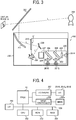
- FIG. 2 is a schematic diagram of a car for which the on-vehicle HUD according to the present example embodiment is provided.
- FIG. 3 is a schematic diagram of the internal structure of the on-vehicle HUD according to the present example embodiment.
- An on-vehicle HUD 200 is installed, for example, in the dashboard of the car 301 that serves as a mobile object.
- the projection light L which is the light for projecting an image, that is emitted from the on-vehicle HUD 200 disposed in the dashboard is reflected at a front windshield 302 that serves as a light transmission member, and is headed for a driver 300.
- the driver 300 can visually recognize a HUD display image such as a navigation image, which will be described later, as a virtual image.
- a combiner that serves as a light transmission member may be disposed on the inner wall of the front windshield 302, and the driver 300 may visually recognizes a virtual image formed by the projection light L that is reflected by the combiner.
- the optical system or the like of the on-vehicle HUD 200 is configured such that the distance from the driver 300 to a virtual image G becomes equal to or longer than 5 meters (m).
- the distance from the driver 300 to the virtual image G is about 2 m.
- the driver 300 observes a point at infinity ahead of the vehicle, or observes a preceding vehicle a few tens of meters ahead of the vehicle.
- the crystalline lenses of the eyes need to be moved widely because the focal length greatly varies.
- the time required to adjust the focus of the eyes and focus on the virtual image G becomes longer, and it takes a long time to recognize the detail of the virtual image G. What is worse, the eyes of the driver 300 tend to get tired. Moreover, it is difficult for the driver to realize the detail of the virtual image G, and it is difficult to use the virtual image G to appropriately provide information to the driver.
- the distance to the virtual image G is equal to or longer than 5 m as in the present embodiment, the amount of movement in the crystalline lenses of the eyes is reduced to a less amount of movement than the background art, and the time required to adjust the focus of the eyes and focus on the virtual image G becomes shorter. Accordingly, the driver 300 can recognize the detail of the virtual image G at an early stage, and the possible tiredness of the eyes of the driver 300 can be reduced. Moreover, it becomes easier for the driver to realize the detail of the virtual image G, and it is easy to use the virtual image G to appropriately provide information to the driver.
- the convergence motion of the eyes are usually required.
- the convergence motion is a major factor in achieving the desired sense of distance or depth perception to an object to be visually recognized.
- the display is controlled such that the perception distance of the virtual image G will be perceived by motion parallax. If the convergence motion occurs to the eyes to focus on the virtual image G when the display is controlled as above, the sense of distance (change in perception distance) or the depth perception (difference in perception distance), which are expected to be brought by a motion parallax, cannot be perceived as desired. Accordingly, if the convergence motion occurs to the eyes, the driver cannot perceive the information as intended by the configuration according to the present embodiment. Note that such configuration will be described later, and the effect is estimated in view of the difference or change in the perception distance of an image.
- the driver When the distance to the virtual image G is equal to or greater than 5 m, the driver can focus on the virtual image G with almost no convergence motion in the eyes. Accordingly, the sense of distance (change in perception distance) or the depth perception (difference in perception distance), which are expected to be brought by a motion parallax, can be perceived as desired in absence of the convergence motion of the eyes. As described above, according to the present embodiment, the driver perceive the information as intended in view of the sense of distance or depth perception of an image.
- the on-vehicle HUD 200 includes, in the HUD 230, red, green, and blue laser beam sources 201R, 201G, and 201B, collimator lenses 202, 203, and 204 that are provided for the laser beam sources 201R, 201G, and 201B, respectively, two dichroic mirrors 205 and 206, a light quantity adjuster 207, an optical scanner 208 that scans light, a free-form surface mirror 209, a microlens array 210 as a light dispersing member, and a projector mirror 211 that serves as a light reflecting member.
- a light source unit 220 includes the laser beam sources 201R, 201G, and 201B, the collimator lenses 202, 203, and 204, and the dichroic mirrors 205 and 206, and these elements are unitized by an optical housing.
- Each of the laser beam sources 201R, 201G, and 201B may be an LD (semiconductor laser element).
- the wavelength of the laser-beam bundle that is emitted from the red laser beam source 201R is, for example, 640 nanometer (nm).
- the wavelength of the laser-beam bundle that is emitted from the green laser beam source 201G is, for example, 530 nm.
- the wavelength of the laser-beam bundle that is emitted from the blue laser beam source 201B is, for example, 445 nm.
- the on-vehicle HUD 200 projects the intermediate image formed on the microlens array 210 onto the front windshield 302 of the vehicle 301, such that the driver 300 can visually recognize the magnified intermediate image as a virtual image G.
- the laser beams of the RGB colors emitted from the laser beam sources 201R, 201G, and 201B are approximately collimated by the collimator lenses 202, 203, and 204, and are combined by the two dichroic mirrors 205 and 206.
- the light quantity of the combined laser beam is adjusted by the light quantity adjuster 207, and then the adjusted laser beam is two-dimensionally scanned by the mirror of the optical scanner 208.
- the scanned light L' that is two-dimensionally scanned by the optical scanner 208 is reflected by the free-form surface mirror 209 so as to correct the distortion, and then is collected and condensed to the microlens array 210. Accordingly, an intermediate image is drawn.
- the microlens array 210 is used as a light dispersing member that individually disperses and emits the laser-beam bundle of each pixel of the intermediate image (i.e., each point of the intermediate image).
- any other light dispersing member may be used.
- a liquid crystal display (LCD) or a vacuum fluorescent display (VFD) may be used as a method of forming the intermediate image G'.
- the laser scanning system is desired as in the present embodiment.
- a non-image area of the display area on which the virtual image G is displayed is slightly irradiated with light, and it is difficult to completely shut such light to the non-image area.
- the non-image area disturbs the visual recognizability of the sight ahead of the vehicle 301.
- the light that irradiates the non-image area of the display area on which the virtual image G is displayed can be completely shut by switching off the laser beam sources 201R, 201G, and 201B.
- the non-image area does not disturb the visual recognizability of the sight ahead of the vehicle 301 as the light from the on-vehicle HUD 200 that may irradiate the non-image area can be completely shut.
- the display needs to be controlled such that only the brightness of the warning image gradually increases among the various kinds of images displayed in the display area 700.
- the laser scanning system is suitable for such cases where the display is controlled such that the brightness of a part of the images displayed in the display area 700 is selectively increased.
- the brightness of the images other than the warning image also increases among the various kinds of images displayed in the display area 700. In such cases, the difference in brightness cannot be increased between the warning image and the other images. Accordingly, the degree of the warning cannot be sufficiently enhanced by gradually increasing the brightness of the warning image.
- the optical scanner 208 uses a known actuator driver system such as a micro-electromechanical systems (MEMS) to incline the mirror to the main-scanning direction and the sub-scanning direction, and two-dimensionally scans (raster-scans) the laser beams that enter the mirror.
- MEMS micro-electromechanical systems
- the mirror is controlled in synchronization with the timing at which the laser beam sources 201R, 201G, and 201B emit light.
- the configuration of the optical scanner 208 is not limited to the present embodiment described above, but the optical scanner 208 may be configured, for example, by a mirror system that includes two mirrors that pivot or rotate around the two axes that are orthogonal to each other.
- FIG. 4 is a block diagram illustrating the hardware configuration of a control system of the on-vehicle HUD 200 according to the present embodiment.
- the control system of the on-vehicle HUD 200 includes a field programmable gate array (FPGA) 251, a central processing unit (CPU) 252, a read only memory (ROM) 253, a random access memory (RAM) 254, an interface (I/F) 255, a bus line 256, a laser diode (LD) driver 257, and a MEMS controller 258.
- the FPGA 251 uses the LD driver 257 to control the operation of the laser beam sources 201R, 201G, and 201B of the light source unit 220.
- the FPGA 251 uses the MEMS controller 258 to controlling the operation of a MEMS 208a of the optical scanner 208.
- the CPU 252 controls the operation of the on-vehicle HUD 200.
- the ROM 253 stores various kinds of programs such as an image processing program that is executed by the CPU 252 to control the operation of the on-vehicle HUD 200.
- the RAM 254 is mainly used as a working area in which the CPU 252 executes a program.
- the I/F 255 allows the on-vehicle HUD 200 to communicate with an external controller such as a controller area network (CAN) of the vehicle 301.
- CAN controller area network
- the on-vehicle HUD 200 is connected to an object recognition device 100, a vehicle navigation device 400, and various kinds of sensor device 500 through the CAN of the vehicle 301.
- the object recognition device 100, the vehicle navigation device 400, and the sensor device 500 will be described later in detail.
- FIG. 5 is a block diagram illustrating an outline of the configuration of an information provision system for a driver according to the present embodiment.
- an information acquisition unit that obtains for-driver information to be provided for a driver via a virtual image G
- the object recognition device 100, the vehicle navigation device 400, and the sensor device 500 are provided.
- the on-vehicle HUD 200 according to the present embodiment includes the HUD 230 that serves as an image-light projection device, and the image controller 250 that serves as a display controller.
- the information acquisition unit according to the present embodiment is provided for the vehicle 301, but the vehicle 301 may use an external information acquisition unit to obtain the information input from the external information acquisition unit through a means of communication.
- FIG. 6 is a schematic block diagram illustrating the hardware configuration of the object recognition device 100 according to the present embodiment.
- the object recognition device 100 according to the present embodiment includes a stereo camera 110 that captures an area ahead of the vehicle 301 as a captured area, and an information processing unit 120 that performs image processing to recognize a prescribed object existing in the captured area according to the image data captured by the stereo camera 110.
- the stereo camera 110 may be replaced with a combination of a monocular camera that serves as an imaging unit, and a laser radar (millimeter-wave radar) that serves as a distance measuring equipment.
- the stereo camera 110 includes a first camera unit 110A for a left eye and a second camera unit 110B for a right eye, and these two camera units are combined together in parallel.
- Each of the camera unit 110A and the camera unit 110B includes a lens 115, an image sensor 116, and a sensor controller 117.
- the image sensor 116 may be composed of, for example, a charge-coupled device (CCD) or a complementary metal oxide semiconductor (CMOS).
- CMOS complementary metal oxide semiconductor
- the sensor controller 117 controls, for example, the exposure of the image sensor 116, the reading of an image, the communication with an external circuit, and the sending of the image data.
- the stereo camera 110 is disposed near the rear-view mirror provided for the front windshield 302 of the vehicle 301.
- the information processing unit 120 includes a data bus line 121, a serial bus line 122, central processing unit (CPU) 123, a field programmable gate array (FPGA) 124, a read only memory (ROM) 125, a random access memory (RAM) 126, a serial interface (I/F) 127, and a data interface (I/F) 128.
- CPU central processing unit
- FPGA field programmable gate array
- ROM read only memory
- RAM random access memory
- I/F serial interface
- I/F data interface
- the stereo camera 110 is connected to the information processing unit 120 through the data bus line 121 and the serial bus line 122.
- the CPU 123 controls, for example, the sensor controllers 117 of the stereo camera 110, the entire operation of the information processing unit 120, and the execution of image processing.
- the brightness image data of the images that are captured by the image sensors 116 of the camera unit 110A and the camera unit 110B are written into the RAM 126 of the information processing unit 120 through the data bus line 121.
- the control data for changing the exposure value of a sensor from the CPU 123 or the FPGA 124, the control data for changing the image reading parameter, various kinds of setting data, or the like are transmitted and received through the serial bus line 122.
- the FPGA 124 performs processing that needs to be done in real time on the image data stored in the RAM 126, such as gamma correction, distortion correction (collimation of an image on the right and left), parallax computation using block matching, to generate a parallax image, and writes the generated parallax image into the RAM 18 again.
- a recognition program is stored for recognizing a prescribed object including a three-dimensional object such as a vehicle or pedestrian, a boundary line for lanes such as a white line on the road, and a curbstone or median strip arranged by the roadside.
- the recognition program is an example of an image processing program.
- the CPU 123 obtains CAN information such as vehicle speed, acceleration, a rudder angle, and a yaw rate from the sensor device 500 through the data I/F 128.
- the data I/F 128 may be, for example, a CAN of the vehicle 301.
- the CPU 123 performs image processing using the brightness image and parallax image stored in the RAM 126, according to the recognition program stored in the ROM 125, and recognizes an object such as a preceding vehicle 350 or a traffic lane line.
- the recognition-result data of an object is supplied, for example, to the image controller 250 and an external device such as a vehicle drive control unit, through the serial I/F 127.
- the vehicle drive control unit uses the recognition-result data of an object to perform brake control, speed control, steering control, or the like of the vehicle 301, and implements, for example, cruise control in which the vehicle 301 automatically tracks a preceding vehicle so as to maintain a prescribed following distance, and an automatic brake control in which the collision with an obstacle ahead of the vehicle is avoided or attenuated.
- the vehicle navigation device 400 may be any known vehicle navigation device provided for a vehicle or the like.
- the vehicle navigation device 400 outputs information used for generating a route navigation image to be displayed on a virtual image G, and the information output from the vehicle navigation device 400 is input to the image controller 250.
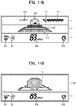
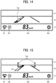
- the information output from the vehicle navigation device 400 includes, for example, as illustrated in FIG. 1 , the number of the lanes (traffic lanes) of the road on which the vehicle 301 is traveling, the distance left before the next point of direction change (e.g., right turn, left turn, and turning point), and an image that indicates information such as the direction of the next direction change.
- the on-vehicle HUD 200 displays navigation images such as a lane indicator image 711, a path indicator image 721, a remaining distance indicator image 722, an intersection or the like name indicator image 723, on an upper display area A or middle display area B of the display area 700.
- images indicating road-specific information is displayed on a lower display area C of the display area 700.
- the road-specific information is also input from the vehicle navigation device 400 to the image controller 250.
- the image controller 250 uses the on-vehicle HUD 200 to display the road-specific information such as a road-name display image 701, a speed limit display image 702, and a no-passing zone display image 703 on the lower display area C of the display area 700.
- the sensor device 500 includes one or two or more sensors that detect various kinds of information such as the behavior of the vehicle 301, the state of the vehicle 301, and the environment around the vehicle 301.
- the sensor device 500 outputs sensing information used for generating an image to be displayed as a virtual image G, and the information output from the sensor 500 is input to the image controller 250.
- a vehicle speed display image 704 indicating the vehicle speed of the vehicle 301 (i.e., the textual image of "83 km/h" in FIG. 1 ) is displayed on the lower display area C of the display area 700.
- the vehicle-speed information included in the CAN information of the vehicle 301 is input from the sensor device 500 to the image controller 250, and the image controller 250 controls the on-vehicle HUD 200 to display the textual image indicating the vehicle speed on the lower display area C of the display area 700.
- the sensor device 500 includes, for example, a laser radar or imaging device that detects the distance from another vehicle, a pedestrian, or construction such as a guard rail and a utility pole, which exist around (ahead of, on the side of, in the rear of) the vehicle 301, a sensor that detects the external environmental information (e.g., outside air temperature, brightness, and weather) of the vehicle 301, a sensor that detects the driving action (e.g., braking action, and the degree of acceleration) of the driver 300, a sensor that senses the amount of the fuel remaining in the fuel tank of the vehicle 301, and a sensor that senses the state of various kinds of vehicle-borne equipment such as an engine and a battery.
- the on-vehicle HUD 200 can display the information as a virtual image G. Accordingly, the information can be provided to the driver 300.
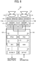
- FIG. 7 is a schematic block diagram illustrating the hardware configuration of the image controller 250.
- a CPU 251, a RAM 252, a ROM 253, an input data interface (I/F) 254, and an output data interface (I/F) 255 are connected to each other via a data bus line.
- I/F 254 for example, various kinds of recognition-result data output from the object recognition device 100, the sensing information output from the sensor device 500, and various kinds of information output from the vehicle navigation device 400 are input.
- a control signal for the on-vehicle HUD 200 is output.
- the CPU 251 executes various kinds of computer program such as an information-provision control program, which is stored, for example, in the ROM 253, to control the image controller 250 to perform various kinds of control and process as will be described later.
- for-driver information that the on-vehicle HUD 200 provides for a driver via a virtual image G may be any information.
- the for-driver information is broadly divided into passive information and active information.
- the passive information is the information that is passively recognized by a driver at the timing when a prescribed information provision condition is met. Accordingly, the passive information includes the information that is provided to the driver at the timing when the on-vehicle HUD 200 is configured, and the passive information includes the information whose provision timing has a certain relation with the detail of the information.
- the passive information includes, for example, security information for driving, and route navigation information.
- the security information for driving includes, for example, the following-distance information indicating the distance between the vehicle 301 and the preceding vehicle 350 (i.e., a following-distance presenting image 712 as will be described later), and information including urgent matters for driving (e.g., warning information such as an instruction for urgent action to be taken by a driver, or attention attracting information).
- the following-distance information indicating the distance between the vehicle 301 and the preceding vehicle 350 (i.e., a following-distance presenting image 712 as will be described later)
- information including urgent matters for driving e.g., warning information such as an instruction for urgent action to be taken by a driver, or attention attracting information.
- the route navigation information indicates a route to a prescribed destination, and such a route is provided to a driver by any known vehicle navigation device.
- the route navigation information includes, for example, lane information (i.e., the lane indicator image 711) indicating a lane to be taken at an upcoming intersection, and direction-change instruction information indicating a direction change to be made at the next intersection or branch point where the direction is to be changed from the straight-ahead direction.
- the direction-change instruction information includes, for example, path indicating information (i.e., the path indicator image 721) that indicates the path to be taken at the next intersection or branch point, remaining distance information (i.e., the remaining distance indicator image 722) indicating the distance to the intersection or branch point where the direction change is to be made, and name information of the intersection or branch point (i.e., the intersection or the like name indicator image 723).
- path indicating information i.e., the path indicator image 721
- remaining distance information i.e., the remaining distance indicator image 722
- name information of the intersection or branch point i.e., the intersection or the like name indicator image 723
- the active information is the information that is actively recognized by a driver at the timing specified by the driver himself or herself.
- the active information is to be provided to the driver only when he or she wishes.
- the active information includes information where the timing of its provision has low or no relevance to the detail of the information.
- the active information is usually displayed for a long time or displayed continuously.
- the road-specific information of the road on which the vehicle 301 is traveling, the vehicle-speed information (i.e., the vehicle speed display image 704) of the vehicle 301, the current-time information are included in the active information.
- the road-specific information includes, for example, the road-name information (i.e., the road-name display image 701), the regulation information of the road such as speed limit (i.e., the speed limit display image 702 and the no-passing zone display image 703), and other kinds of information of the road useful for the driver.
- the for-driver information which is broadly divided into the active information and the passive information as described above, is displayed in a corresponding area of the display area 700 where a virtual image is displayable. More specifically, in the present embodiment, the display area 700 is divided into three display areas in the up-and-down directions. Then, a passive-information image that corresponds to the passive information is displayed in the upper display area A and the middle display area B of the obtained three display areas, and an active-information image that corresponds to the active information is displayed in the lower display area C. Note that some of the active-information image may be displayed upper display area A and the middle display area B. In such cases, the active-information image is displayed in such a manner that a higher priority is given to the viewability of the passive-information image displayed in the upper display area A and the middle display area B.
- the passive information according to the present embodiment includes instruction information indicating an instruction given to the driver 300, like the route navigation information or the like.
- instruction information indicating an instruction given to the driver 300, like the route navigation information or the like.
- the feelings of anxiety that a driver may have e.g., the driver may be anxious about what action he/she has to make in the near future
- direction-change instruction images including the path indicator image 721, the remaining distance indicator image 722, and the intersection or the like name indicator image 723 are displayed, indicating a direction change to be made at the next intersection or branch point where the direction is to be changed from the straight-ahead direction.
- the path indicator image 721, the remaining distance indicator image 722, and the intersection or the like name indicator image 723 may be referred to simply as direction-change instruction images 721, 722, and 723, for the sake of explanatory convenience.
- the display of a plurality of instruction images with varying operational sequences is controlled such that an instruction image with a lower priority for the driver in the operational sequence is displayed on an upper side of the display area 700.
- the direction-change instruction images 721, 722, and 723 with a lower priority in the operational sequence than the lane indicator image 711 is displayed on an upper side of the display area 700 than the lane indicator image 711. Accordingly, the situation can be avoided in which the driver confuses among the operational sequences of the instruction indicated by lane indicator image 711 and the direction-change instruction images 721, 722, and 723. Such avoidance is achieved for the reasons given below.
- an object that is ahead of the vehicle 301 and is far away from the moving vehicle 301 has a high affinity of perception for a far future event
- an object that is ahead of the vehicle 301 and is close to the moving vehicle 301 has a high affinity of perception for a close future event.
- an indicator image of far future i.e., an instruction image with a lower priority in the operational sequence such as the direction-change instruction images 721, 722, and 723 is displayed so as to overlap with a position where an object that is far away from the moving vehicle 301 ahead of the vehicle 301 is visually recognized
- an indicator image of near future or now i.e., an instruction image with a high priority in the operational sequence such as the lane indicator image 711 is displayed so as to overlap with a position where an object that is close to the moving vehicle 301 ahead of the vehicle 301 is visually recognized.
- the display area 700 in which the lane indicator image 711 and the direction-change instruction images 721, 722, and 723 with different operational sequences are displayed is positioned on a lower side of the sight viewed through the front windshield 302.
- the lane indicator image 711 and the direction-change instruction images 721, 722, and 723 are displayed under the observation point of the driver so as to overlap with the sight viewed through the front windshield 302.
- an object that is far away from the vehicle 301 is visually recognized on an upper side of the sight
- an object that is close to the vehicle 301 is visually recognized on a lower side of the sight.
- the direction-change instruction images 721, 722, and 723 with a lower priority in the operational sequence than the lane indicator image 711 is displayed on an upper side of the display area 700 than the lane indicator image 711. More specifically, the direction-change instruction images 721, 722, and 723 with a lower priority in the operational sequence are displayed in the upper display area A of the display area 700 that overlaps with a point where an object that is far away from the moving vehicle 301 ahead of the vehicle 301 is visually recognized, and the lane indicator image 711 with a higher priority in the operational sequence is displayed in the middle display area B of the display area 700 that overlaps with a point where an object that is close to the moving vehicle 301 ahead of the vehicle 301 is visually recognized.
- the sequence of operation of the instruction can be recognized by the driver through intuition, and the situation can be avoided in which the driver confuses among the operational sequences of the instruction indicated by the instruction images.
- the affinity of recognition is not considered and the position at which the lane indicator image 711 is displayed and the position at which the direction-change instruction images 721, 722, and 723 are displayed are, for example, inverted up-and-down direction with reference to the present embodiment or rearranged horizontally, it becomes difficult for the driver to recognize the operational sequence through intuition as the driver is disturbed by the sense of distance or the sense of time as described above.
- instruction images that indicate the instructions with the same operational sequence are horizontally arranged. More specifically, the three direction-change instruction images 721, 722, and 723 that are displayed in the upper display area A are horizontally arranged in the upper display area A to indicate the direction-change instruction information indicating a direction change to be made at the next intersection or branch point where the direction is to be changed from the straight-ahead direction. According to the sense of distance or the sense of time as described above, the three direction-change instruction images 721, 722, and 723 that are horizontally arranged at the same position in the up-and-down directions can easily be recognized through intuition that these images indicate the instruction to be dealt with around the same time. Accordingly, the driver 300 can appropriately recognize the information of the direction-change instruction images 721, 722, and 723.
- a stereoscopic image is used as the virtual image G that is displayed in the display area 700. More specifically, perspective images are used as the lane indicator image 711 and the following-distance presenting image 712 that are displayed in the middle display area B of the display area 700.
- the following-distance presenting image 712 is displayed such that the vanishing point approximately matches the observation point of the driver. Due to this configuration, while the driver 300 is driving, he or she can easily perceive the depth of the following-distance presenting image 712.
- a perspective image in which the thickness of the horizontal lines becomes thinner towards the upper side and the brightness of the horizontal lines becomes lower towards the upper side is used. Due to this configuration, while the driver 300 is driving, he or she can even more easily perceive the depth of the following-distance presenting image 712.
- the depth perception is created for the virtual image G that is displayed in the display area 700 by making use of such a stereoscopic image as described above. Accordingly, the driver can easily perceive the relevance between the distance to the object in the sight ahead of the vehicle and the position of the image displayed in display area 700 in the up-and-down directions. As a result, the above-described affinity of recognition is more easily achieved, and the driver can easily recognize through intuition that the instruction of the lane indicator image 711 displayed in the middle display area B of the display area 700 is to be dealt with prior to the instruction of the direction-change instruction images 721, 722, and 723 displayed in the upper display area A of the display area 700.
- lane indicator image 711 is also drawn by the perspective drawing method in a similar manner to the following-distance presenting image 712, such that the lane indicator image 711 heads for the same vanishing point as that of the following-distance presenting image 712.
- the lane indicator image 711 is to provide the instruction to the driver. For this reason, if a lower priority is given to the creation of the depth perception to the lane indicator image 711 and a higher priority is given to the accurate provision of the instruction indicated by the lane indicator image 711 to the driver, for example, the brightness of the images of the three arrows that make up the lane indicator image 711 may be increased towards the leading ends of the arrows.
- the laser scanning system provides easier brightness control for each image area compared with the other systems, and thus a greater contrast between a low-brightness area and a high-brightness area is achieved. For this reason, the laser scanning system effectively enables increasing the brightness of the leading ends of the arrows as described above to provide information to the driver in an accurate manner. While it is easier to create the depth perception when the brightness becomes lower towards the upper side, the brightness of the lane indicator image 711 becomes higher towards the upper side in the above cases. Although it is not possible to create the depth perception in the above cases, the visual recognizability of the arrows increases by increasing the brightness of the leading ends of the arrows. Accordingly, the instruction that is indicated by the lane indicator image 711 can more accurately provided to the driver. It is to be noted that the depth perception does not significantly deteriorate in the above cases as the lane indicator image 711 is drawn using the perspective drawing method.
- a motion-parallax image is used as the virtual image G.
- the motion parallax indicates the parallax that is caused as the position of the eyes of the driver 300 (i.e., the position of the viewpoint) moves.
- the driver 300 perceives the distance and depth dimension with reference to an object, which are influenced by a motion parallax due to the displacement in movement where an object closer to the driver in the sight ahead of the vehicle appears to move in a greater amount and an object more distant from the driver in the sight ahead of the vehicle appears to move in a smaller amount when the position of the eyes of the driver 300 moves.
- a driver camera 150 that monitors the positions of the eyes of the driver 300 (i.e., the location of the viewpoint) is disposed near the rear-view mirror provided for the front windshield 302 of the vehicle 301.
- the driver camera 150 serves as a viewpoint detector.
- the driver camera 150 be disposed around the median line drawn from the driver 300 who sits in the driver's seat.
- the driver camera 150 be disposed, for example, on an upper side so as not to obstruct the view of the driver 300.
- the driver camera 150 is a monocular camera that is configured to capture an area where the driver 300 who sits in the driver's seat and is driving the vehicle is expected to move his/her head.
- the driver camera 150 includes, for example, a lens, an image sensor, and a sensor controller.
- a stereo camera may be used as the driver camera 150 in order to keep track of the position of the eyes of the driver in the forward and backward directions.
- the brightness image data of the images captured by the driver camera 150 is input to image controller 250.
- the image controller 250 uses the CPU 251 to execute an information-provision control program stored in the ROM 253 or the like, and recognizes the position of the eyes of the driver 300 based on the brightness image data obtained from the driver camera 150.
- the position of the head of the driver 300 is recognized in a simplified manner based on the brightness image data obtained from the driver camera 150, and the position of the eyes of the driver 300 is estimated based on the results of the recognition.
- any desired known recognition method may be adopted as a method of recognizing the position of the head of the driver 300.
- FIG. 8 is a schematic diagram illustrating a method of processing a virtual image G with a depth perception that is created by a motion parallax, according to the present embodiment.
- the driver 300 can perceive that the object Oa, the object Ob, and the object Oc exist with the distance La, distance Lb, and distance Lc, respectively, away from the driver 300.
- the virtual image G is displayed with the distance of 5 m away from the driver 300, and any of the images on the virtual image G is displayed with the distance of 5 m away from the driver 300.
- a plurality of images on the virtual image G are modified using the motion parallax as described above such that the images are perceived by the driver 300 as if the images are displayed with varying distances.
- the image controller 250 recognizes the position of the head of the driver 300 at prescribed time intervals based on the brightness image data of the images captured by the driver camera 150. Then, the image controller 250 calculates the driver's head movement amount Dd that indicates the amount where the head of driver 300 has moved during the prescribed time intervals. In this case, the position at which the virtual image G is visually recognized with the distance of 5 m moves by the amount "Da".
- the positions of the images that are displayed in the lower display area C are fixed in the display area 700. Accordingly, the position at which the images displayed in the lower display area C are visually recognized moves by the amount "Da", which is the same as the amount in which the virtual image G moves. As a result, the driver 300 perceives the images displayed in the lower display area C with the distance La (5 m).
- the image controller 250 shifts the images displayed in the middle display area B of the display area 700 of the virtual image G to the reverse direction to the direction in which the head of the driver has moved in the display area 700 by the amount "Da-Db", based on the calculated driver's head movement amount Dd. Accordingly, the position at which the images displayed in the middle display area B are visually recognized by the driver 300 moves by the amount "Db". As a result, the driver 300 perceives the images displayed in the middle display area B with the distance Lb.
- the image controller 250 shifts the images displayed in the upper display area A of the display area 700 of the virtual image G to the reverse direction to the direction in which the head of the driver has moved in the display area 700 by the amount "Da-Dc", based on the calculated driver's head movement amount Dd. Accordingly, the position at which the images displayed in the upper display area A are visually recognized by the driver 300 moves by the amount "Dc". As a result, the driver 300 perceives the images displayed in the upper display area A with the distance Lc.
- the virtual image G is projected while controlling, based on the calculated driver's head movement amount Dd, the amount "Db" and "Dc" by which the positions at which the images displayed in the upper display area A and the middle display area B are visually recognized move. Accordingly, the driver 300 perceives the images as if the images displayed in the middle display area B (including, for example, the lane indicator image 711 and the following-distance presenting image 712) are displayed at a position further than the images displayed in the lower display area C (including, for example, the road-name display image 701, the speed limit display image 702, and the no-passing zone display image 703).
- the driver 300 perceives the images as if the images displayed in the upper display area A (including, for example, the direction-change instruction images 721, 722, and 723) are displayed at a position even further than the images displayed in the middle display area B.
- the images on the virtual image G that are actually displayed with the same distance can be modified such that the driver 300 perceives these images with varying distances. By so doing, the depth perception of the virtual image G can be created.
- the images that are displayed in the middle display area B are divided into a plurality of sections up-and-down directions, and the amount of the movement is varied for each of the sections based on the driver's head movement amount Dd.
- the driver 300 perceives the images displayed in the middle display area B as if an image on the upper side is displayed with a longer distance.
- the motion parallax are used for the lane indicator image 711 and the following-distance presenting image 712 that are displayed in the middle display area B.
- the depth dimension of the virtual image G can further be created.
- FIG. 9 is a schematic diagram illustrating an example image of the situation in which the direction is to be changed at an upcoming intersection, according to the present embodiment.
- the example image illustrated in FIG. 1 is switched to the example image as illustrated in FIG. 9 .
- a path indicator image 717 that is similar to the path indicator image 721 displayed in the upper display area A of the example image illustrated in FIG. 1 is displayed in the middle display area B.
- the driver 300 can know that he/she only has to follow the path indicator image 717 displayed in the middle display area B at the next intersection or branch point.
- a downward-pointing sign 725 is displayed at the position of the path indicator image 721 displayed in the upper display area A of the example image illustrated in FIG. 1 .
- the downward-pointing sign 725 guides the line of sight of the driver 300 to the path indicator image 717 displayed in the middle display area B. Accordingly, the driver 300 can easily recognize the path indicator image 717 displayed in the middle display area B.
- a distance sensor such as the object recognition device 100 and the sensor device 500 recognizes the following distance to the preceding vehicle 350.
- the image controller 250 receives the recognition-result data that indicates the distance to an object ahead of the vehicle, and controls, based on the recognition-result data, the display position, brightness, color, shape, or the like of the preceding vehicle image 724 displayed in the upper display area A of the display area 700 or the following-distance presenting image 712 displayed in the middle display area B of the display area 700.
- the driver 300 can visually recognize how much the following distance to the preceding vehicle 350 is becoming narrow by the changes made to the following-distance presenting image 712 and the preceding vehicle image 724.
- FIGS. 10A to 10E are schematic diagrams of example images where images indicating the preceding-vehicle approaching information change according to the following distance to the preceding vehicle 350, according to the present embodiment. Note that these example images illustrated in FIGS. 10A to 10E are referred to as first example images. Although the destination is not set to the vehicle navigation device 400 and no instruction image regarding the route navigation information is displayed in the first example images, the first example images illustrated in FIGS. 10A to 10E can be applied to cases in which an instruction image regarding the route navigation information is displayed.
- the image controller 250 displays in the middle display area B the following-distance presenting image 712 that consist of five horizontal lines where the length becomes shorter and the brightness becomes lower towards the upper side. Note that in the example image illustrated in FIG. 10A , the overall brightness of the following-distance presenting image 712 is low. In this example image, no image is displayed in the upper display area A.
- the image controller 250 increases the brightness of the following-distance presenting image 712 that is displayed in the middle display area B. Further, in the first example image, the image of the lowest horizontal line of the following-distance presenting image 712 is replaced with a vehicle bumper image 712a that is a line where the thickness is greater and the both ends of the line is extended downward and outward.
- the vehicle bumper image 712a recalls the front bumper of the vehicle 301 to the driver 300.
- the preceding vehicle image 724 with low brightness that resembles the rear view of a preceding vehicle is displayed in the upper display area A.
- the preceding vehicle image 724 is controlled in view of the driving parallax so as to be perceived by the driver 300 with the perception distance (Lc) same as that of the other images displayed in the upper display area A.
- the image controller 250 increases the brightness of the following-distance presenting image 712 displayed in the middle display area B and the brightness of the preceding vehicle image 724 displayed in the upper display area A to a degree greater than that of the example image illustrated in FIG. 10B . Further, in the first example image, the image of the second horizontal line from the bottom of the following-distance presenting image 712 is changed to the vehicle bumper image 712a. By so doing, compared with the image illustrated in FIG. 10B , the vehicle bumper image 712a appears closer to the preceding vehicle 724. Accordingly, compared with the image illustrated in FIG. 10B , the driver 300 can know that the vehicle 301 is getting closer to the preceding vehicle 350.
- the preceding vehicle image 724 illustrated in FIG. 10C is controlled in view of the driving parallax so as to be perceived by the driver 300 with a closer perception distance Le1 (Lb ⁇ Le1 ⁇ Lc) than that of the other images displayed in the upper display area A.
- Le1 Le1
- the driver perceives that the preceding vehicle image 724 is closer.
- the driver 300 can know that the vehicle 301 is getting closer to the preceding vehicle 350 with even stronger sensation.
- the image controller 250 increases the brightness of the following-distance presenting image 712 displayed in the middle display area B and the brightness of the preceding vehicle image 724 displayed in the upper display area A to a degree greater than that of the example image illustrated in FIG. 10C . Further, in the first example image, the image of the third horizontal line from the bottom of the following-distance presenting image 712 is changed to the vehicle bumper image 712a. By so doing, compared with the image illustrated in FIG. 10C , the vehicle bumper image 712a appears even closer to the preceding vehicle 724. Accordingly, compared with the image illustrated in FIG. 10C , the driver 300 can know that the vehicle 301 is getting even closer to the preceding vehicle 350.
- the preceding vehicle image 724 illustrated in FIG. 10D is controlled in view of the driving parallax so as to be perceived by the driver 300 with an even closer perception distance Le2 (Lb. ⁇ Le2 ⁇ Le1) than that of the other images displayed in the upper display area A.
- Le2 Lb. ⁇ Le2 ⁇ Le1
- the driver perceives that the preceding vehicle image 724 is closer.
- the driver 300 can know with stronger sensation that the vehicle 301 is getting even closer to the preceding vehicle 350.
- the image controller 250 changes the following-distance presenting image 712 that is displayed in the middle display area B to a brake warning image 714 where the textual image "BRAKE! in a red trapezoid-shaped box.
- the visual recognizability of the preceding vehicle image 724 may be reduced by decreasing the brightness of the preceding vehicle image 724 displayed in the upper display area A or by removing the solid fill of the preceding vehicle image 724 displayed in the upper display area A. Accordingly, the brake warning image 714 stands out, which is desirable.
- the preceding vehicle image 724 displayed in the upper display area A may be hidden such that the brake warning image stands out.
- the laser scanning system is adopted in the above case where the preceding vehicle image 724 displayed in the upper display area A is hidden, the light can completely be cut off at non-image areas, and the brake warning image even more stands out, increasing the warning effect.
- the prescribed safe range or the prescribed braking-required distance described as above may be fixed in advance, or may vary according to the vehicle speed or the like of the vehicle 301.
- a method of making the driver 300 realize that following distance to the preceding vehicle 350 is too short is not limited to the first example images described above, but may be example images as illustrated in FIG. 11A and FIG. 11B . In the following description, these example images illustrated in FIG. 11A and FIG. 11B are referred to as second example images.
- images indicating the preceding-vehicle approaching information change according to following distance to the preceding vehicle 350 in the second example images. More specifically, in place of the five horizontal lines of the following-distance presenting image 712 of the first example images described as above, a following-distance presenting image 715 consisting of a trapezoid image drawn towards the vanishing point using the perspective drawing method is used in the second example image of FIG. 11A , and the trapezoid image of the following-distance presenting image 715 is divided into four in the up-and-down directions.
- a high-brightness trapezoidal section 715 in the second example image of FIG. 11A moves upward to get close to the preceding vehicle image 724 as the distance to the preceding vehicle 350 becomes shorter.
- the example image illustrated in FIG. 11A corresponds to the image illustrated in FIG. 10D
- the example image illustrated in FIG. 11A is an example of when the preceding vehicle 350 is recognized and the following distance to the preceding vehicle 350 is shorter than the prescribed safe range but longer than a prescribed braking-required distance.
- the destination is set to the vehicle navigation device 400 and an instruction image regarding the route navigation information is displayed.
- the path indicator image 721 is displayed near the center of the upper display area A in the right and left directions (near the vanishing point), and the remaining distance indicator image 722 and the intersection or the like name indicator image 723 are displayed on right and left sides, respectively.
- the direction-change instruction images 721, 722, and 723 may be all hidden in the upper display area A.
- the instruction that is indicated by the direction-change instruction images 721, 722, and 723 i.e., instruction for future action
- the driver 300 may become anxious about it.
- the driver may take time to search for the moved direction-change instruction images 721, 722, and 723. In such cases, the instruction that is indicated by the direction-change instruction images 721, 722, and 723 cannot appropriately be provided to the driver 300.
- the direction-change instruction images 721, 722, and 723 are continuously displayed in the upper display area A. Accordingly, even when the preceding vehicle image 724 is to be displayed in the upper display area A, the instruction that is indicated by the direction-change instruction images 721, 722, and 723 can appropriately be provided to the driver 300.
- the preceding vehicle image 724 is displayed in the upper display area A where the direction-change instruction images 721, 722, and 723 are displayed, it is not necessary for all of the direction-change instruction images 721, 722, and 723 to be continuously displayed in the upper display area A.
- the intersection or the like name indicator image 723 may selectively be hidden.
- the image controller 250 displays a brake warning image 716 that is displayed across the upper display area A and the middle display area B.
- the brake warning image 716 is a combination of a red image obtained by magnifying the preceding vehicle image 724 to be displayed in the upper display area A and a red image of all the trapezoidal sections of the following-distance presenting image 715 according to the second example image illustrated in FIG. 11A .
- all the direction-change instruction images 721, 722, and 723 are hidden such that the brake warning image 716 stands out.
- a method of making the driver 300 realize that following distance to the preceding vehicle 350 is too short may be example images as illustrated in FIG. 12A, FIG. 12B, and FIG. 12C .
- these example images illustrated in FIG. 12A, FIG. 12B, and FIG. 12C are referred to as third example images.
- images indicating the preceding-vehicle approaching information change according to following distance to the preceding vehicle 350 in the third example images.
- a simple figure image 713 that consists of a simple figure is used in place of the following-distance presenting image 712 or the preceding vehicle image 724 that resembles the rear view of a vehicle.
- the display is controlled such that the perception distance to the simple figure image 713 becomes shorter as the distance to the preceding vehicle 350 becomes shorter.
- the display is controlled such that the simple figure image 713 is enlarged and the brightness of the simple figure image 713 becomes higher as the distance to the preceding vehicle 350 becomes shorter.
- the display is controlled such that the perception distance influenced by the motion parallax of the simple figure image 713 becomes shorter as the distance to the preceding vehicle 350 becomes shorter.
- the display is controlled such that the perception distance of the virtual image G becomes the same as or close to the perception distance (Lc) of display area A, for example, 10 m. More specifically, the image controller 250 shifts the position of the simple figure image 713 displayed in the middle display area B of the display area 700 of the virtual image G according to the driver's head movement amount Dd calculated from the image data captured by driver camera 150. Accordingly, the display is controlled in such a manner that the perception distance of the simple figure image 713 becomes about 10 m as described above.
- the display is controlled such that the perception distance becomes shorter (for example, 7 m) than the perception distance in the case of FIG. 12A .
- the image controller 250 shifts the position of the simple figure image 713 displayed in the middle display area B of the display area 700 of the virtual image G according to the driver's head movement amount Dd calculated from the image data captured by driver camera 150. Accordingly, the display is controlled in such a manner that the perception distance of the simple figure image 713 becomes about 7 m as described above.
- the display is controlled such that the perception distance becomes shorter (for example, 4 m) than the perception distance in the case of FIG. 12B .
- the image controller 250 shifts the position of the simple figure image 713 displayed in the middle display area B of the display area 700 of the virtual image G according to the driver's head movement amount Dd calculated from the image data captured by driver camera 150.
- the display is controlled in such a manner that the perception distance of the simple figure image 713 becomes about 4 m as described above. Note that this perception distance (4 m) is shorter than the distance of the virtual image G (5m). Such a short perception distance can also be achieved by the control of the display as described above.
- example images will be referred to as fourth example images in the following description.
- the example image displayed in FIG. 9 is used to provide to the driver 300 the information indicating to what direction the direction is to be changed and at what intersection the direction is to be changed.
- the example images illustrated in FIG. 13A, FIG. 13B, and FIG. 13C are used.
- the path indicator image 717 is displayed in the display area 700 so as to overlap with the actual intersection that is visually recognized by the driver through the front windshield 302.
- the remaining distance information which is passive information, that indicates the distance to the intersection or branch point where the direction change is to be made is provided to the driver 300 using the remaining distance indicator image 722.
- the remaining distance indicator image 722 indicates the remaining distance with the image of the numerical value.
- the perception distance of the path indicator image 717 is changed according to the remaining distance information. By so doing, the remaining distance information indicating the distance to the intersection or branch point where the direction change is to be made is provided to the driver 300 by changing perception distance of the path indicator image 717.
- the image controller 250 shifts the position of the path indicator image 717 displayed in the middle display area B of the display area 700 of the virtual image G according to the driver's head movement amount Dd calculated from the image data captured by driver camera 150.
- the display is controlled in such a manner that the perception distance of the path indicator image 717 matches the actual distance to the intersection.
- the actual distance to the intersection may be obtained, for example, from the vehicle navigation device 400.
- the perception distance of the path indicator image 717 does not necessarily have to match the actual distance to the intersection. It is intended that the driver will recognize the actual distance to the intersection is getting short as the perception distance of the path indicator image 717 is gradually narrowed.
- information whose provision is particularly desired by the driver 300 may be displayed in the middle display area B as a warning image.
- Such information is the information relating to the road on which the vehicle 301 is traveling, including the information relating to the road closed to vehicles or the information relating to the restricted or designated road.
- a school- commuting-route warning image 718 that indicates that the road on which the vehicle 301 is traveling is a school commuting route is displayed in the middle display area B.
- This example image will be referred to as a fifth example image in the following description.
- the image controller 250 obtains road-specific information of the road on which the vehicle 301 is traveling from the various kinds of data or the like output from the vehicle navigation device 400. Then, when the obtained road-specific information is the information to be displayed in the middle display area B, the image controller 250 displays in the middle display area B a warning image that corresponds to the obtained road-specific information.
- the middle display area B is an area in which an instruction image indicating the instruction to be dealt with prior to the other multiple instructions is displayed. For this reason, when such a warning image is displayed in the middle display area B as in the fifth example image, the driver can recognize through intuition that the road on which the vehicle 301 is currently traveling may be closed, restricted, or designated as specified by the warning image.
- the warning image of such a detection may be displayed in the middle display area B.
- a person is one of the objects that require the greatest attention for vehicles, and that a person is an entity to be dealt with immediately.
- a human-shaped warning image 719 is displayed in the middle display area B as in the example image illustrated in FIG. 15 .
- This example image will be referred to as a sixth example image in the following description. More specifically, the image controller 250 uses the object recognition device 100 and the sensor device 500 to recognize a person ahead of the vehicle.
- the image controller 250 receives the recognition-result data that indicates the distance to the person ahead of the vehicle, and displays the human-shaped warning image 719 in the middle display area B based on the received recognition-result data.
- the school-commuting-route warning image 718 which is described as above with reference to the fifth example image, is displayed together in the sixth example image.
- An information provision device such as the on-vehicle HUD 200 includes an image-light projection device such as the HUD 230 configured to project an image light to a light transmission member such as the front windshield 302 so as to display a for-driver information image indicating for-driver information to be provided for a driver 300 of a mobile object such as the vehicle 301 in a prescribed display area 700 that is visually recognized by the driver 300 through the light transmission member ahead of the mobile object in a direction of travel.
- an image-light projection device such as the HUD 230 configured to project an image light to a light transmission member such as the front windshield 302 so as to display a for-driver information image indicating for-driver information to be provided for a driver 300 of a mobile object such as the vehicle 301 in a prescribed display area 700 that is visually recognized by the driver 300 through the light transmission member ahead of the mobile object in a direction of travel.
- the information provision device includes a distance sensor such as the object recognition device 100 configured to detect a relative distance of an object to be detected such as the preceding vehicle 350 existing around the mobile object in the direction of travel, a viewpoint detector such as the driver camera 150 configured to detect a location of a viewpoint of the driver, and a display controller such as the image controller 250 configured to control the image-light projection device by changing a position at which an object image such as the preceding vehicle image 724 indicating the object to be detected is displayed according to a result of detection generated by the viewpoint detector so as to change a perception distance of the driver influenced by a motion parallax of the object image according to the relative distance of the object to be detected in the direction of travel detected by the distance sensor.
- a distance sensor such as the object recognition device 100 configured to detect a relative distance of an object to be detected such as the preceding vehicle 350 existing around the mobile object in the direction of travel
- a viewpoint detector such as the driver camera 150 configured to detect a location of a viewpoint of the driver
- a display controller such as
- an image-light projection device to project an image to provide to the driver with the relative movement information of an object existing around the mobile object (environmental object information). For example, situations in which it is difficult for the driver to visually recognize an object around the mobile object due to poor visibility around the mobile object are considered. If an object-representing image corresponding to the object is displayed using a HUD and the environmental object information is provided to the driver, he or she can drive safely. Even when it is not difficult for the driver to visually recognize an object around the vehicle, the provision of the environmental object information indicating the motion of an object that could be overlooked due to the carelessness or the like of the driver can help the driver drive safe.
- the environmental object information is to be provided to the driver in such a way, it is effective to make the driver perceive the object-representing image in such a manner that the depth dimension changes according to the relative movement with reference to the mobile object. By so doing, the driver can easily recognize the environmental object information.
- the application of a motion parallax is effective in making the driver perceive the environmental object information in the above manner.
- the perception distance of the object image that is displayed in a prescribed display area ahead of the mobile object in the direction of travel can be varied according to the relative distance in the direction of travel between the mobile object and the object to be detected existing around the mobile object (relative distance in the direction of travel of the mobile object).
- the driver is made to perceive the perception distance of the object image with a motion parallax. Accordingly, it becomes easy to make the driver recognize the environmental object information including the motion of the object to be detected approaching or moving away from the mobile object.
- the object to be detected is another mobile object such as the preceding vehicle 350 traveling ahead of the mobile object.
- the driver 300 it becomes easy to make the driver 300 to recognize the information that the distance to another preceding mobile object is getting short such as the preceding-vehicle approaching information.
- An information provision device such as the on-vehicle HUD 200 includes an image-light projection device such as the HUD 230 configured to project an image light to a light transmission member such as the front windshield 302 so as to display a for-driver information image indicating for-driver information to be provided for a driver 300 of a mobile object such as the vehicle 301 in a prescribed display area 700 that is visually recognized by the driver 300 through the light transmission member ahead of the mobile object in a direction of travel.
- an image-light projection device such as the HUD 230 configured to project an image light to a light transmission member such as the front windshield 302 so as to display a for-driver information image indicating for-driver information to be provided for a driver 300 of a mobile object such as the vehicle 301 in a prescribed display area 700 that is visually recognized by the driver 300 through the light transmission member ahead of the mobile object in a direction of travel.
- the prescribed display area 700 includes an active-information image display area such as the lower display area C that continues displaying an active-information image such as the road-name display image 701, the speed limit display image 702, the no-passing zone display image 703, and the vehicle speed display image 704 indicating active information such as road-specific information and vehicle-speed information to be actively recognized by the driver, and a passive-information image display area such as the upper display area A and the middle display area B that temporarily displays, at a timing when a prescribed information provision condition is met, a passive-information image such as the lane indicator image 711, the direction-change instruction images 721, 722, and 723, the following-distance presenting image 712, and the preceding vehicle image 724 indicating passive information such as route navigation information and preceding-vehicle approaching information to be passively recognized by the driver.
- an active-information image display area such as the lower display area C that continues displaying an active-information image such as the road-name display image 701, the speed limit display image 702, the no-passing zone display image
- the information provision device includes a viewpoint detector such as the driver camera 150 configured to detect a location of a viewpoint of the driver, and a display controller such as the image controller 250 configured to control the image-light projection device by changing a position at which the passive-information image is displayed in the passive-information image display area according to a result of detection generated by the viewpoint detector so as to make a perception distance Lb or Lc of the driver influenced by the motion parallax of the passive-information image become longer than a perception distance La of the driver of the active-information image displayed in the active-information image display area.
- a viewpoint detector such as the driver camera 150 configured to detect a location of a viewpoint of the driver
- a display controller such as the image controller 250 configured to control the image-light projection device by changing a position at which the passive-information image is displayed in the passive-information image display area according to a result of detection generated by the viewpoint detector so as to make a perception distance Lb or Lc of the driver influenced by the motion parallax of the passive-information image become longer
- the passive information that is passively recognized by a driver is the information to be provided to the driver at the timing determined by the information provision device, and is the information whose provision timing has a certain relation with the detail of the information. For this reason, the passive-information image that indicates the passive information is to be recognized by the driver 300 as soon as the passive-information image is displayed.
- the active information to be actively recognized by the driver is the information to be provided to the driver only when he or she wishes.
- the active information includes information where the timing of its provision has low or no relevance to the detail of the information.
- the active information is usually displayed for a long time or displayed continuously.
- the driver perceives the active-information image and the passive-information image as if the passive-information image is displayed further than the active-information image due to a motion parallax. For this reason, it is easier for the driver to recognize the passive-information image than the active-information image because the driver focuses on a remote point when he or she is driving. Accordingly, the driver can easily notice a newly-displayed passive-information image even when an active-information image is displayed prior to the passive-information image. Accordingly, the driver 300 can easily recognize the passive-information image as soon as it is displayed, and the passive information can be provided to the driver without delay.
- the driver 300 has willingness to obtain the active information, and thus the less visibility of the active-information image than the passive-information image does not cause a problem in the provision of the active information.
- the active information is usually displayed for a long time or displayed continuously as described above, in fact, high visibility of the active-information image may distract the attention of the driver who is driving, which is disadvantageous.
- the passive information includes a plurality of pieces of instruction information indicating varying instructions to the driver of the mobile object
- the display controller controls the image-light projection device so as to display one or a plurality of instruction images corresponding to the instruction information such as the lane indicator image 711 and the direction-change instruction images 721, 722, and 723 with a lower priority for the driver in an operational sequence is displayed on an upper side of the passive-information image display area
- the driver usually has both a sense of distance that an object existing ahead of the moving mobile object gets close to the current position as the time passes by, and a sense of time that a future event gets close to the current time as the time passes by. Further, an object existing ahead of the moving mobile object reaches the mobile object in a shorter time as the distance between the object and the mobile object is shorter, and it takes a longer time for the object existing ahead of the moving mobile object to reach the position of the mobile object as the distance between the object and the mobile object is longer.
- an object that is ahead of the mobile object and is far away from the moving mobile object has a high affinity of recognition for a far future event
- an object that is ahead of the mobile object and is close to the moving mobile object has a high affinity of recognition for a nearer future event
- the display of a plurality of instruction images with varying operational sequences is controlled in view of such an affinity such that an instruction image with a lower priority for the driver in the operational sequence is displayed on an upper side of the prescribed display area.
- the image-light projection device projects an image light onto the light transmission member so as to display the passive-information image display area on a lower side of a sight visually recognized by the driver through the light transmission member ahead of the mobile object in the direction of travel.
- the driver 300 who visually recognizes through the light transmission member the sight ahead of the mobile object in the direction of travel usually drives while observing near the center in the vertical direction of the sight ahead of the mobile object as an observation point.
- the prescribed display area 700 in which a plurality of instruction images are displayed is positioned on a lower side of the sight ahead of the mobile object.
- a plurality of instruction images are displayed under the observation point of the driver in the vertical direction.
- an object that is far away from the mobile object is visually recognized on an upper side of the sight in the vertical direction, and an object that is close to the mobile object is visually recognized on a lower side of the sight in the vertical direction. Accordingly, the position at which an object is visually recognized in the sight is gradually displaced towards the downside as the mobile object travels forward and gets close to the object.
- the display of a plurality of instruction images with varying operational sequences is controlled such that an instruction image with a lower priority for the driver in the operational sequence is displayed on an upper side of the prescribed display area. Accordingly, the situation in which the driver confuses among the operational sequences of the instruction indicated by the instruction images can be minimized.
- an instruction image of far future i.e., an instruction image with a lower priority in the operational sequence
- an instruction image of near future i.e., an instruction image with a high priority in the operational sequence
- the prescribed display area 700 is positioned on a lower side of the sight ahead of the mobile object and if the position at which the instruction images are displayed are, for example, rearranged horizontally or inverted up-and-down direction with reference to the present embodiment, it becomes difficult for the driver to recognize the operational sequence through intuition as the driver is disturbed by the sense of distance or the sense of time as described above.
- the instruction images indicate instructions to be dealt with by the driver at varying points (e.g., the upcoming intersection, and the next intersection or branch point where the direction is to be changed from the straight-ahead direction) of on a route the mobile object takes. Accordingly, the situation can be avoided in which the driver confuses among the instructions with varying operational sequences indicated by the route navigation information.
- the image-light projection device projects the image light to display the instruction image as a virtual image in the prescribed display area, and distance between a driver and the virtual image is equal to or longer than 5 m.
- the convergence motion of the eyes are usually required. As described above, the convergence motion is a major factor in achieving the desired sense of distance or depth perception to an object to be visually recognized. If the convergence motion occurs to the eyes to focus on the virtual image G when the display is controlled as above, the sense of distance (change in perception distance) or the depth perception (difference in perception distance), which are expected to be brought by a motion parallax, cannot be perceived as desired.
- the distance to the virtual image G is equal to or greater than 5 m as in the Mode G, the driver can focus on the virtual image G with almost no convergence motion in the eyes. Accordingly, the sense of distance (change in perception distance) or the depth perception (difference in perception distance), which are expected to be brought by motion parallax, can be perceived as desired in absence of the convergence motion of the eyes.
- the image-light projection device includes a light emitter such as the light source unit 220 configured to emit an image light according to image data of the instruction image, and an optical scanner such as the optical scanner 208 configured to scan the image light emitted from the light emitter two-dimensionally, and the image-light projection device projects the image light two-dimensionally scanned by the optical scanner to the light transmission member to display the for-driver information image in the prescribed display area.
- a light emitter such as the light source unit 220 configured to emit an image light according to image data of the instruction image
- an optical scanner such as the optical scanner 208 configured to scan the image light emitted from the light emitter two-dimensionally
- the image-light projection device projects the image light two-dimensionally scanned by the optical scanner to the light transmission member to display the for-driver information image in the prescribed display area.
- the present mode it is easier to display a virtual image G with a wide dimension and high brightness than the systems with, for example, the LCD and the VFD. Moreover, according to the present mode, the light that irradiates the non-image area of the display area on which the virtual image G is displayed can be completely shut by preventing the light emitter from emitting an image light. For this reason, if a laser scanning system is adopted as in the Mode H, the non-image area does not disturb the visual recognizability of the sight ahead of the mobile object as the light emitter that may irradiate the non-image area can be completely shut.
- a method of providing information includes projecting an image light to a light transmission member so as to display a for-driver information image indicating for-driver information to be provided for a driver of a mobile object in a prescribed display area that is visually recognized by the driver through the light transmission member ahead of the mobile object in a direction of travel, thereby providing the for-driver information to the driver.
- the method of providing information includes sensing a relative distance of an object to be detected existing around the mobile object in the direction of travel, detecting a location of a viewpoint of the driver, and changing a position at which an object image indicating the object to be detected is displayed according to a result of the detecting so as to change a perception distance of the driver influenced by a motion parallax of the object image according to the relative distance of the object to be detected in the direction of travel detected by the sensing.
- the driver is made to perceive the perception distance of the object image with a motion parallax. Accordingly, it becomes easy to make the driver recognize the environmental object information including the motion of the object to be detected approaching or moving away from the mobile object.
- a computer-readable non-transitory carrier medium stores a program for causing a computer of an information provision device to execute an information-provision control method.
- the information provision device includes an image-light projection device configured to project an image light to a light transmission member so as to display a for-driver information image indicating for-driver information to be provided for a driver of a mobile object in a prescribed display area that is visually recognized by the driver through the light transmission member ahead of the mobile object in a direction of travel, a distance sensor configured to sense a relative distance of an object to be detected existing around the mobile object in the direction of travel, and a viewpoint detector configured to detect a location of a viewpoint of the driver.
- the information-provision control method includes controlling the image-light projection device by changing a position at which an object image indicating the object to be detected is displayed according to a result of detection generated by the viewpoint detector so as to change a perception distance of the driver influenced by a motion parallax of the object image according to the relative distance of the object to be detected in the direction of travel detected by the distance sensor.
- the driver is made to perceive the perception distance of the object image with a motion parallax. Accordingly, it becomes easy to make the driver recognize the environmental object information including the motion of the object to be detected approaching or moving away from the mobile object.
- a method of providing information includes projecting an image light to a light transmission member so as to display a for-driver information image indicating for-driver information to be provided for a driver of a mobile object in a prescribed display area that is visually recognized by the driver through the light transmission member ahead of the mobile object in a direction of travel, thereby providing the for-driver information to the driver.
- the prescribed display area includes an active-information image display area that continues displaying an active-information image indicating active information to be actively recognized by the driver, and a passive-information image display area that temporarily displays, at a timing when a prescribed information provision condition is met, a passive-information image indicating passive information to be passively recognized by the driver.
- the method of providing information includes detecting a location of a viewpoint of the driver, by changing a position at which the passive-information image is displayed in the passive-information image display area according to a result of the detecting, and controlling the projecting so as to make a perception distance of the driver influenced by the motion parallax of the passive-information image become longer than a perception distance of the driver of the active-information image displayed in the active-information image display area.
- the driver it becomes easier for the driver to recognize the passive-information image than the active-information image because the driver focuses on a remote point when he or she is driving. Accordingly, the driver can easily notice a newly-displayed passive-information image even when an active-information image is displayed prior to the passive-information image. Accordingly, the driver 300 can easily recognize the passive-information image as soon as it is displayed, and the passive information can be provided to the driver without delay.
- a computer-readable non-transitory carrier medium stores a program for causing a computer of an information provision device to execute an information-provision control method.
- the information provision device includes an image-light projection device configured to project an image light to a light transmission member so as to display a for-driver information image indicating for-driver information to be provided for a driver of a mobile object in a prescribed display area that is visually recognized by the driver through the light transmission member ahead of the mobile object in a direction of travel, and a viewpoint detector configured to detect a location of a viewpoint of the driver.
- the prescribed display area includes an active-information image display area that continues displaying an active-information image indicating active information to be actively recognized by the driver, and a passive-information image display area that temporarily displays, at a timing when a prescribed information provision condition is met, a passive-information image indicating passive information to be passively recognized by the driver.
- the information-provision control method includes controlling the image-light projection device by changing a position at which the passive-information image is displayed in the passive-information image display area according to a result of detection generated by the viewpoint detector so as to make a perception distance of the driver influenced by the motion parallax of the passive-information image become longer than a perception distance of the driver of the active-information image displayed in the active-information image display area.
- the driver it becomes easier for the driver to recognize the passive-information image than the active-information image because the driver focuses on a remote point when he or she is driving. Accordingly, the driver can easily notice a newly-displayed passive-information image even when an active-information image is displayed prior to the passive-information image. Accordingly, the driver 300 can easily recognize the passive-information image as soon as it is displayed, and the passive information can be provided to the driver without delay.
- the programs mentioned above may be distributed or made available in a state being recorded on recording medium such as a compact disc read only memory (CD-ROM).
- the programs may be distributed or made available by distributing or receiving the signal, which carries the program and is transmitted from a certain transmitter, through a transmission medium such as public telephone lines, a private line, and other sorts of network.
- the transmission medium may carry only a part of the computer program.
- the above-mentioned signal that carries a program is a computer data signal that is implemented in a prescribed carrier including a computer program.
- a method of transmitting a computer program from a certain transmitter includes cases in which the data that makes up the program is continuously transmitted and cases in which the data that makes up the program is intermittently transmitted.
- any one of the above-described and other methods of the present invention may be embodied in the form of a computer program stored in any kind of storage medium.
- storage mediums include, but are not limited to, flexible disk, hard disk, optical discs, magneto-optical discs, magnetic tapes, nonvolatile memory cards, ROM, etc.
- any one of the above-described and other methods of the present invention may be implemented by ASICs, prepared by interconnecting an appropriate network of conventional component circuits, or by a combination thereof with one or more conventional general-purpose microprocessors and/or signal processors programmed accordingly.
- the present invention can be implemented in any convenient form, for example using dedicated hardware, or a mixture of dedicated hardware and software.
- the present invention may be implemented as computer software implemented by one or more networked processing apparatuses.
- the network can comprise any conventional terrestrial or wireless communications network, such as the Internet.
- the processing apparatuses can compromise any suitably programmed apparatuses such as a general purpose computer, personal digital assistant, mobile telephone (such as a WAP or 3G-compliant phone) and so on. Since the present invention can be implemented as software, each and every aspect of the present invention thus encompasses computer software implementable on a programmable device.
- the computer software can be provided to the programmable device using any conventional carrier medium.
- the carrier medium can compromise a transient carrier medium such as an electrical, optical, microwave, acoustic or radio frequency signal carrying the computer code.
- a transient carrier medium such as an electrical, optical, microwave, acoustic or radio frequency signal carrying the computer code.
- An example of such a transient medium is a TCP/IP signal carrying computer code over an IP network, such as the Internet.
- the carrier medium can also comprise a storage medium for storing processor readable code such as a floppy disk, hard disk, CD ROM, magnetic tape device or solid state memory device.
- the hardware platform includes any desired kind of hardware resources including, for example, a CPU, a RAM, and a hard disk drive (HDD).
- the CPU may be implemented by any desired kind of any desired number of processor.
- the RAM may be implemented by any desired kind of volatile or non-volatile memory.
- the HDD may be implemented by any desired kind of non-volatile memory capable of storing a large amount of data.
- the hardware resources may additionally include an input device, an output device, or a network device, depending on the type of the apparatus. Alternatively, the HDD may be provided outside of the apparatus as long as the HDD is accessible.
- the CPU such as a cache memory of the CPU
- the RAM may function as a physical memory or a primary memory of the apparatus, while the HDD may function as a secondary memory of the apparatus.
Landscapes
- Engineering & Computer Science (AREA)
- Radar, Positioning & Navigation (AREA)
- Remote Sensing (AREA)
- Automation & Control Theory (AREA)
- Mechanical Engineering (AREA)
- Physics & Mathematics (AREA)
- General Physics & Mathematics (AREA)
- Transportation (AREA)
- Combustion & Propulsion (AREA)
- Chemical & Material Sciences (AREA)
- Multimedia (AREA)
- General Engineering & Computer Science (AREA)
- Theoretical Computer Science (AREA)
- Human Computer Interaction (AREA)
- Instrument Panels (AREA)
- Traffic Control Systems (AREA)
- Mechanical Optical Scanning Systems (AREA)
- Control Of Indicators Other Than Cathode Ray Tubes (AREA)
- Controls And Circuits For Display Device (AREA)
Applications Claiming Priority (1)
| Application Number | Priority Date | Filing Date | Title |
|---|---|---|---|
| JP2014250084A JP6485732B2 (ja) | 2014-12-10 | 2014-12-10 | 情報提供装置、情報提供方法及び情報提供用制御プログラム |
Publications (2)
| Publication Number | Publication Date |
|---|---|
| EP3031655A1 EP3031655A1 (en) | 2016-06-15 |
| EP3031655B1 true EP3031655B1 (en) | 2019-05-22 |
Family
ID=54703780
Family Applications (1)
| Application Number | Title | Priority Date | Filing Date |
|---|---|---|---|
| EP15195457.5A Active EP3031655B1 (en) | 2014-12-10 | 2015-11-19 | Information provision device, information provision method, and carrier medium storing information provision program |
Country Status (3)
| Country | Link |
|---|---|
| US (2) | US10152120B2 (ru) |
| EP (1) | EP3031655B1 (ru) |
| JP (1) | JP6485732B2 (ru) |
Families Citing this family (92)
| Publication number | Priority date | Publication date | Assignee | Title |
|---|---|---|---|---|
| US9582006B2 (en) * | 2011-07-06 | 2017-02-28 | Peloton Technology, Inc. | Systems and methods for semi-autonomous convoying of vehicles |
| DE112014006588T5 (de) * | 2014-04-14 | 2017-03-23 | Mitsubishi Electric Corporation | Anzeigesteuervorrichtung, Anzeigesteuerverfahren und Anzeigesteuerprogramm |
| KR101632873B1 (ko) * | 2014-09-05 | 2016-07-01 | 현대모비스 주식회사 | 장애물 검출 시스템 및 방법 |
| KR101867915B1 (ko) * | 2015-01-16 | 2018-07-19 | 현대자동차주식회사 | 차량에서 웨어러블 기기를 이용한 기능 실행 방법 및 이를 수행하는 차량 |
| JP6661883B2 (ja) * | 2015-02-09 | 2020-03-11 | 株式会社デンソー | 車両用表示制御装置及び車両用表示制御方法 |
| JP6520668B2 (ja) * | 2015-02-09 | 2019-05-29 | 株式会社デンソー | 車両用表示制御装置及び車両用表示ユニット |
| DE112015006458B4 (de) * | 2015-04-17 | 2019-05-23 | Mitsubishi Electric Corporation | Anzeigesteuervorrichtung, Anzeigesystem, Anzeigesteuerverfahren und Anzeigesteuerprogramm |
| CN107923761B (zh) * | 2015-08-20 | 2021-04-16 | 三菱电机株式会社 | 显示控制装置、显示装置及显示控制方法 |
| JP6703747B2 (ja) | 2015-09-18 | 2020-06-03 | 株式会社リコー | 情報表示装置、情報提供システム、移動体装置、情報表示方法及びプログラム |
| US11119315B2 (en) * | 2015-10-15 | 2021-09-14 | Maxell, Ltd. | Information display apparatus |
| JP6350492B2 (ja) * | 2015-11-26 | 2018-07-04 | トヨタ自動車株式会社 | 画像表示装置 |
| KR101916993B1 (ko) * | 2015-12-24 | 2018-11-08 | 엘지전자 주식회사 | 차량용 디스플레이 장치 및 그 제어방법 |
| JP6806097B2 (ja) | 2016-02-08 | 2021-01-06 | 株式会社リコー | 画像表示装置及び画像表示方法 |
| JP6741029B2 (ja) | 2016-02-08 | 2020-08-19 | 株式会社リコー | 情報表示装置 |
| EP3415373B1 (en) | 2016-02-10 | 2020-10-07 | Ricoh Company, Ltd. | Information providing device |
| WO2017141829A1 (ja) | 2016-02-18 | 2017-08-24 | 株式会社リコー | 情報提供装置 |
| JP6838248B2 (ja) * | 2016-02-22 | 2021-03-03 | 日立Astemo株式会社 | 情報処理装置 |
| KR101826408B1 (ko) * | 2016-03-03 | 2018-03-22 | 엘지전자 주식회사 | 디스플레이 장치 및 이를 포함하는 차량 |
| US10281923B2 (en) | 2016-03-03 | 2019-05-07 | Uber Technologies, Inc. | Planar-beam, light detection and ranging system |
| JP6344417B2 (ja) * | 2016-03-18 | 2018-06-20 | トヨタ自動車株式会社 | 車両用表示装置 |
| EP3239660B1 (en) * | 2016-04-26 | 2019-06-19 | Volvo Car Corporation | Method and system for selectively enabling a user device on the move to utilize digital content associated with entities ahead |
| EP3246664A3 (en) | 2016-05-19 | 2018-02-14 | Ricoh Company, Ltd. | Information processing system and information display apparatus |
| JP6870447B2 (ja) | 2016-05-20 | 2021-05-12 | 株式会社リコー | Hud装置、車両装置、情報表示方法。 |
| US10240943B2 (en) * | 2016-06-17 | 2019-03-26 | Here Global B.V. | Method, apparatus and computer program product for a navigation user interface |
| JP6834537B2 (ja) | 2017-01-30 | 2021-02-24 | 株式会社リコー | 表示装置、移動体装置、表示装置の製造方法及び表示方法。 |
| CN109996697B (zh) * | 2016-09-16 | 2022-06-21 | 富士胶片株式会社 | 投影型显示装置、显示控制方法、及记录介质 |
| JP6373323B2 (ja) * | 2016-09-30 | 2018-08-15 | 本田技研工業株式会社 | 移動体制御装置、及び移動体 |
| JP6752679B2 (ja) * | 2016-10-15 | 2020-09-09 | キヤノン株式会社 | 撮像システム |
| CN106985749B (zh) * | 2016-10-25 | 2019-07-05 | 蔚来汽车有限公司 | 基于车道线灭点的hud显示系统和方法 |
| JP6643969B2 (ja) * | 2016-11-01 | 2020-02-12 | 矢崎総業株式会社 | 車両用表示装置 |
| US10916225B2 (en) | 2016-11-24 | 2021-02-09 | Nippon Seiki Co., Ltd. | Attention calling display apparatus |
| JP6654999B2 (ja) * | 2016-12-12 | 2020-02-26 | 株式会社Soken | 物標検出装置 |
| US9922566B1 (en) * | 2016-12-20 | 2018-03-20 | GM Global Technology Operations LLC | Passing zone advisory systems and methods |
| JP2018105737A (ja) * | 2016-12-27 | 2018-07-05 | トヨタ紡織株式会社 | アイポイント測定装置、及びアイポイント測定方法 |
| JP6922217B2 (ja) | 2016-12-28 | 2021-08-18 | 株式会社リコー | 表示装置、物体装置及び表示方法 |
| JP6972549B2 (ja) | 2016-12-28 | 2021-11-24 | 株式会社リコー | Hud装置、車両装置及び表示方法 |
| JP2018105838A (ja) * | 2016-12-28 | 2018-07-05 | 株式会社リコー | 情報表示装置及び車両装置 |
| US10407079B1 (en) * | 2017-01-19 | 2019-09-10 | State Farm Mutual Automobile Insurance Company | Apparatuses, systems and methods for determining distracted drivers associated with vehicle driving routes |
| JP2018118580A (ja) * | 2017-01-24 | 2018-08-02 | 株式会社デンソー | 車両用表示装置 |
| JP6930120B2 (ja) | 2017-02-02 | 2021-09-01 | 株式会社リコー | 表示装置、移動体装置及び表示方法。 |
| KR102449834B1 (ko) * | 2017-02-17 | 2022-09-29 | 스미도모쥬기가이고교 가부시키가이샤 | 작업기계용 주변감시 시스템 |
| CN110506305A (zh) * | 2017-03-31 | 2019-11-26 | 日本精机株式会社 | 提醒注意装置 |
| WO2018193708A1 (ja) * | 2017-04-19 | 2018-10-25 | マクセル株式会社 | ヘッドアップディスプレイ装置およびその表示制御方法 |
| JP6695049B2 (ja) * | 2017-05-10 | 2020-05-20 | パナソニックIpマネジメント株式会社 | 表示装置及び表示制御方法 |
| US11187910B2 (en) * | 2017-05-22 | 2021-11-30 | Nippon Seiki Co., Ltd. | Head-up display device for adjusting display distances of virtual images |
| FR3068481B1 (fr) * | 2017-06-29 | 2019-07-26 | Airbus Operations (S.A.S.) | Systeme et procede d'affichage pour un aeronef |
| JP7266257B2 (ja) * | 2017-06-30 | 2023-04-28 | パナソニックIpマネジメント株式会社 | 表示システム、及び表示システムの制御方法 |
| JP6855350B2 (ja) * | 2017-08-08 | 2021-04-07 | アルパイン株式会社 | ヘッドアップディスプレイ装置、ナビゲーション装置、表示方法 |
| DE102017214225B3 (de) * | 2017-08-15 | 2018-11-22 | Volkswagen Aktiengesellschaft | Verfahren zum Betreiben eines Fahrerassistenzsystems eines Kraftfahrzeugs sowie Kraftfahrzeug |
| JP6806650B2 (ja) * | 2017-09-11 | 2021-01-06 | 本田技研工業株式会社 | 車両用表示システム |
| JP2019048577A (ja) * | 2017-09-11 | 2019-03-28 | 本田技研工業株式会社 | 車両用外板パネル、車両用表示カーテン、車両用表示幌及び車両用表示システム |
| KR102427854B1 (ko) * | 2017-09-25 | 2022-08-01 | 삼성전자주식회사 | 영상 렌더링 방법 및 장치 |
| US10895741B2 (en) * | 2017-10-03 | 2021-01-19 | Industrial Technology Research Institute | Ultra-wide head-up display system and display method thereof |
| JP6606148B2 (ja) * | 2017-10-06 | 2019-11-13 | 本田技研工業株式会社 | 車両制御装置 |
| KR102306790B1 (ko) * | 2017-11-08 | 2021-09-30 | 삼성전자주식회사 | 컨텐츠 시각화 장치 및 방법 |
| WO2019109336A1 (en) * | 2017-12-08 | 2019-06-13 | Baidu.Com Times Technology (Beijing) Co., Ltd. | Stereo camera depth determination using hardware accelerator |
| CN108229386B (zh) * | 2017-12-29 | 2021-12-14 | 百度在线网络技术(北京)有限公司 | 用于检测车道线的方法、装置和介质 |
| CN109991739A (zh) * | 2017-12-29 | 2019-07-09 | 深圳点石创新科技有限公司 | 车载抬头显示器 |
| DE102018204254B4 (de) * | 2018-03-20 | 2020-12-03 | Volkswagen Aktiengesellschaft | Verfahren zur Berechnung einer Einblendung von Zusatzinformationen für eine Anzeige auf einer Anzeigeeinheit, Vorrichtung zur Durchführung des Verfahrens sowie Kraftfahrzeug und Computerprogramm |
| DE102019106738B4 (de) * | 2018-03-27 | 2021-11-04 | Panasonic Intellectual Property Management Co., Ltd. | Anzeigesystem, elektronisches Spiegelsystem, fahrendes Fahrzeug und Anzeigeverfahren |
| JP2019172245A (ja) * | 2018-03-29 | 2019-10-10 | 株式会社リコー | 画像制御装置、表示装置、移動体、画像制御方法、及びプログラム |
| US11059421B2 (en) | 2018-03-29 | 2021-07-13 | Honda Motor Co., Ltd. | Vehicle proximity system using heads-up display augmented reality graphics elements |
| JP6726883B2 (ja) * | 2018-03-30 | 2020-07-22 | パナソニックIpマネジメント株式会社 | 表示システム、移動体、及び表示システムの制御方法 |
| US10532697B2 (en) * | 2018-06-14 | 2020-01-14 | International Business Machines Corporation | Augmented reality-based roadside content viewing within primary field of view |
| JP7105173B2 (ja) * | 2018-11-02 | 2022-07-22 | 京セラ株式会社 | 3次元表示装置、ヘッドアップディスプレイ、移動体、およびプログラム |
| TWI686747B (zh) * | 2018-11-29 | 2020-03-01 | 財團法人金屬工業研究發展中心 | 移動載具全周障礙迴避之方法 |
| EP3671692A1 (en) * | 2018-12-19 | 2020-06-24 | Ningbo Geely Automobile Research & Development Co. Ltd. | Time for passage of a platoon of vehicles |
| AU2019100368B4 (en) * | 2019-01-25 | 2019-11-28 | Norman BOYLE | A driverless impact attenuating traffic management vehicle |
| WO2020162343A1 (ja) * | 2019-02-04 | 2020-08-13 | 日本電気株式会社 | 車両管理装置、車両管理方法、プログラムを記憶する記憶媒体 |
| DE102019206490B3 (de) * | 2019-05-06 | 2020-03-26 | Volkswagen Aktiengesellschaft | Parkassistenzsystem für ein Kraftfahrzeug, Verfahren zur Einparkunterstützung für ein Kraftfahrzeug, Computerprogramm und computerlesbares Speichermedium |
| US11222476B2 (en) * | 2019-05-14 | 2022-01-11 | Panasonic Automotive Systems Company Of America, Division Of Panasonic Corporation Of North America | System to add parallax to video for augmented reality head up display |
| JP7120963B2 (ja) * | 2019-05-21 | 2022-08-17 | 矢崎総業株式会社 | 表示ユニット |
| JP2020199793A (ja) * | 2019-06-06 | 2020-12-17 | マツダ株式会社 | 車両用メーター表示装置 |
| JP7351478B2 (ja) | 2019-07-26 | 2023-09-27 | 株式会社小松製作所 | 表示システム、遠隔操作システム、及び表示方法 |
| JP6692981B1 (ja) * | 2019-09-13 | 2020-05-13 | マレリ株式会社 | 表示装置及び表示方法 |
| CN114761857A (zh) * | 2019-11-05 | 2022-07-15 | 京瓷株式会社 | 平视显示器、平视显示器系统以及移动体 |
| JP7402083B2 (ja) * | 2020-02-28 | 2023-12-20 | 本田技研工業株式会社 | 表示方法、表示装置及び表示システム |
| CN111231946B (zh) * | 2020-03-03 | 2021-08-20 | 安徽中科美络信息技术有限公司 | 一种低视距车辆安全行驶控制方法 |
| CN111562877A (zh) * | 2020-04-30 | 2020-08-21 | 联想(北京)有限公司 | 一种图像处理方法及装置 |
| US11919391B2 (en) * | 2020-05-29 | 2024-03-05 | Yazaki Corporation | On-vehicle display apparatus |
| EP3920083A1 (en) * | 2020-06-05 | 2021-12-08 | Aptiv Technologies Limited | Pointing to non-mapped objects outside a vehicle |
| JP2020175889A (ja) * | 2020-06-29 | 2020-10-29 | 株式会社リコー | 情報提供装置、情報提供方法及び情報提供用制御プログラム |
| WO2022024962A1 (ja) * | 2020-07-27 | 2022-02-03 | 日本精機株式会社 | ヘッドアップディスプレイ装置 |
| CN111993889A (zh) * | 2020-08-05 | 2020-11-27 | 华人运通(江苏)技术有限公司 | 车辆仪表控制方法、装置、设备及存储介质 |
| KR20220022340A (ko) * | 2020-08-18 | 2022-02-25 | 삼성전자주식회사 | 컨텐츠를 시각화하는 장치 및 방법 |
| CN112078519A (zh) * | 2020-09-09 | 2020-12-15 | 上海仙塔智能科技有限公司 | 车载全息投影仪控制系统及车载全息投影仪 |
| JP2022086420A (ja) * | 2020-11-30 | 2022-06-09 | 本田技研工業株式会社 | 表示方法、及びシステム |
| US11869361B2 (en) * | 2021-04-01 | 2024-01-09 | Gm Cruise Holdings Llc | Coordinated multi-vehicle routing |
| JP2022184350A (ja) * | 2021-06-01 | 2022-12-13 | マツダ株式会社 | ヘッドアップディスプレイ装置 |
| CN113566836A (zh) * | 2021-06-28 | 2021-10-29 | 阿波罗智联(北京)科技有限公司 | 道路指引方法、装置、电子设备及存储介质 |
| CN113727156B (zh) * | 2021-08-09 | 2023-05-26 | 东风汽车集团股份有限公司 | 基于光线和视线的多自由度车载影音系统调整方法和装置 |
| KR20230168859A (ko) * | 2022-06-08 | 2023-12-15 | 현대모비스 주식회사 | 자동차 조명 장치 및 그 작동 방법 |
Family Cites Families (65)
| Publication number | Priority date | Publication date | Assignee | Title |
|---|---|---|---|---|
| JP3462227B2 (ja) * | 1992-11-13 | 2003-11-05 | 矢崎総業株式会社 | 車両用表示装置 |
| DE4319904C2 (de) * | 1993-06-16 | 2002-11-28 | Siemens Ag | Warngerät zum Anzeigen einer Information in einem Vehikel |
| US7561966B2 (en) * | 2003-12-17 | 2009-07-14 | Denso Corporation | Vehicle information display system |
| ATE552478T1 (de) * | 2004-06-03 | 2012-04-15 | Making Virtual Solid L L C | Navigationsanzeigeverfahren und vorrichtung für unterwegs unter verwendung eines head-up-displays |
| JP4899340B2 (ja) * | 2004-08-02 | 2012-03-21 | 日産自動車株式会社 | 運転感覚調整装置及び運転感覚調整方法 |
| JP2006309090A (ja) | 2005-02-21 | 2006-11-09 | Ricoh Co Ltd | 走査光学系、光走査装置、画像形成装置およびカラー画像形成装置 |
| JP4500738B2 (ja) | 2005-06-20 | 2010-07-14 | 株式会社リコー | 光走査装置・画像形成装置 |
| US7876486B2 (en) | 2006-03-08 | 2011-01-25 | Ricoh Company, Limited | Optical scanning apparatus, optical writing apparatus, and image forming apparatus |
| DE102006011481A1 (de) * | 2006-03-13 | 2007-09-20 | Robert Bosch Gmbh | Verfahren und Vorrichtung zum Unterstützen eines Führens eines Fahrzeugs |
| US7688491B2 (en) | 2006-09-15 | 2010-03-30 | Ricoh Company, Ltd. | Diffractive-optical element, scanning optical system, optical scanner, and image forming apparatus |
| JP4976092B2 (ja) | 2006-09-19 | 2012-07-18 | 株式会社リコー | 光走査装置、およびそれを用いた画像形成装置 |
| US8045248B2 (en) | 2007-03-09 | 2011-10-25 | Ricoh Company, Ltd. | Optical scanning device and image forming apparatus |
| JP2009006968A (ja) | 2007-06-29 | 2009-01-15 | Nippon Seiki Co Ltd | 車両用表示装置 |
| JP2009053379A (ja) | 2007-08-27 | 2009-03-12 | Ricoh Co Ltd | 光走査装置及び画像形成装置 |
| JP2009053378A (ja) | 2007-08-27 | 2009-03-12 | Ricoh Co Ltd | 光走査装置及び画像形成装置 |
| JP4475308B2 (ja) | 2007-09-18 | 2010-06-09 | 株式会社デンソー | 表示装置 |
| JP2009150947A (ja) * | 2007-12-19 | 2009-07-09 | Hitachi Ltd | 車両用ヘッドアップディスプレイ装置 |
| DE102009004432B4 (de) | 2008-01-25 | 2016-12-08 | Denso Corporation | Kraftfahrzeuganzeigevorrichtung zum Anzeigen eines ein vorderes Hindernis umkreisenden Bildflecks |
| JP2009217682A (ja) * | 2008-03-12 | 2009-09-24 | Yazaki Corp | 車両用表示装置 |
| JP2009229752A (ja) * | 2008-03-21 | 2009-10-08 | Toshiba Corp | 表示装置、表示方法及びヘッドアップディスプレイ |
| JP4852062B2 (ja) * | 2008-03-28 | 2012-01-11 | 株式会社東芝 | 単眼用画像表示装置及び単眼用画像表示方法 |
| JP2009246505A (ja) * | 2008-03-28 | 2009-10-22 | Toshiba Corp | 画像表示装置及び画像表示装置 |
| JP2010070066A (ja) * | 2008-09-18 | 2010-04-02 | Toshiba Corp | ヘッドアップディスプレイ |
| JP4686586B2 (ja) * | 2008-09-19 | 2011-05-25 | 株式会社東芝 | 車載用表示装置及び表示方法 |
| JP2010143520A (ja) * | 2008-12-22 | 2010-07-01 | Toshiba Corp | 車載用表示システム及び表示方法 |
| JP5161760B2 (ja) * | 2008-12-26 | 2013-03-13 | 株式会社東芝 | 車載用表示システム及び表示方法 |
| US8330673B2 (en) * | 2009-04-02 | 2012-12-11 | GM Global Technology Operations LLC | Scan loop optimization of vector projection display |
| US8317329B2 (en) * | 2009-04-02 | 2012-11-27 | GM Global Technology Operations LLC | Infotainment display on full-windshield head-up display |
| US8629784B2 (en) * | 2009-04-02 | 2014-01-14 | GM Global Technology Operations LLC | Peripheral salient feature enhancement on full-windshield head-up display |
| US8564502B2 (en) * | 2009-04-02 | 2013-10-22 | GM Global Technology Operations LLC | Distortion and perspective correction of vector projection display |
| JP2011013289A (ja) | 2009-06-30 | 2011-01-20 | Ricoh Co Ltd | 光走査装置及び画像形成装置 |
| US8531766B2 (en) | 2009-07-02 | 2013-09-10 | Ricoh Company, Limited | Polarization-separation device, optical scanning apparatus, and image forming apparatus |
| GB2472773B (en) * | 2009-08-13 | 2015-01-28 | Light Blue Optics Ltd | Head up displays |
| US20120224062A1 (en) * | 2009-08-07 | 2012-09-06 | Light Blue Optics Ltd | Head up displays |
| US8503762B2 (en) * | 2009-08-26 | 2013-08-06 | Jacob Ben Tzvi | Projecting location based elements over a heads up display |
| JP2011059270A (ja) | 2009-09-08 | 2011-03-24 | Nippon Seiki Co Ltd | 車両用表示装置 |
| JP2011064760A (ja) | 2009-09-15 | 2011-03-31 | Nippon Seiki Co Ltd | 車両用表示装置 |
| JP5173031B2 (ja) * | 2009-09-28 | 2013-03-27 | 株式会社東芝 | 表示装置及び表示方法 |
| JP2011073466A (ja) | 2009-09-29 | 2011-04-14 | Nippon Seiki Co Ltd | 車両用表示装置 |
| JP5278292B2 (ja) * | 2009-11-27 | 2013-09-04 | 株式会社デンソー | 情報提示装置 |
| JP5275963B2 (ja) * | 2009-12-08 | 2013-08-28 | 株式会社東芝 | 表示装置、表示方法及び移動体 |
| JP5679175B2 (ja) | 2010-03-24 | 2015-03-04 | 株式会社リコー | 光走査装置及び画像形成装置 |
| JP5691633B2 (ja) | 2010-06-25 | 2015-04-01 | 株式会社リコー | 光走査装置及び画像形成装置 |
| US8896631B2 (en) * | 2010-10-25 | 2014-11-25 | Hewlett-Packard Development Company, L.P. | Hyper parallax transformation matrix based on user eye positions |
| JP5803184B2 (ja) | 2010-11-19 | 2015-11-04 | 株式会社リコー | 画像投影装置、メモリアクセス方法 |
| US8098171B1 (en) * | 2010-12-28 | 2012-01-17 | GM Global Technology Operations LLC | Traffic visibility in poor viewing conditions on full windshield head-up display |
| JP2013061554A (ja) | 2011-09-14 | 2013-04-04 | Ricoh Co Ltd | 画像形成装置、画像形成装置を搭載した車両 |
| US8692739B2 (en) * | 2011-09-22 | 2014-04-08 | GM Global Technology Operations LLC | Dynamic information presentation on full windshield head-up display |
| JP6062041B2 (ja) * | 2012-05-07 | 2017-01-18 | 本田技研工業株式会社 | 道路を基準にした風景のビデオ画像から仮想表示面を生成する方法 |
| JP6015227B2 (ja) * | 2012-08-10 | 2016-10-26 | アイシン・エィ・ダブリュ株式会社 | 交差点案内システム、方法およびプログラム |
| US9607510B1 (en) * | 2012-09-12 | 2017-03-28 | Delorean, Llc | Traffic display with viewing distance control |
| JP5975285B2 (ja) * | 2012-10-05 | 2016-08-23 | 日本精機株式会社 | レーザー走査型表示装置 |
| JP6097382B2 (ja) * | 2013-02-22 | 2017-03-15 | クラリオン株式会社 | 車両用ヘッドアップディスプレー装置 |
| US9047703B2 (en) * | 2013-03-13 | 2015-06-02 | Honda Motor Co., Ltd. | Augmented reality heads up display (HUD) for left turn safety cues |
| US20160054563A9 (en) * | 2013-03-14 | 2016-02-25 | Honda Motor Co., Ltd. | 3-dimensional (3-d) navigation |
| US9064420B2 (en) * | 2013-03-14 | 2015-06-23 | Honda Motor Co., Ltd. | Augmented reality heads up display (HUD) for yield to pedestrian safety cues |
| US10215583B2 (en) * | 2013-03-15 | 2019-02-26 | Honda Motor Co., Ltd. | Multi-level navigation monitoring and control |
| JP6138634B2 (ja) * | 2013-08-29 | 2017-05-31 | アイシン・エィ・ダブリュ株式会社 | ヘッドアップディスプレイ装置 |
| JP6524417B2 (ja) * | 2014-02-05 | 2019-06-05 | パナソニックIpマネジメント株式会社 | 車両用表示装置および車両用表示装置の表示方法 |
| JP6273976B2 (ja) * | 2014-03-31 | 2018-02-07 | 株式会社デンソー | 車両用表示制御装置 |
| JP6271006B2 (ja) * | 2014-06-13 | 2018-01-31 | 三菱電機株式会社 | 虚像表示装置 |
| GB2528446B (en) * | 2014-07-21 | 2021-08-04 | Tobii Tech Ab | Method and apparatus for detecting and following an eye and/or the gaze direction thereof |
| US10539791B2 (en) * | 2014-09-02 | 2020-01-21 | Ostendo Technologies, Inc. | Split exit pupil multiple virtual image heads-up display systems and methods |
| GB2534151A (en) * | 2015-01-14 | 2016-07-20 | Jaguar Land Rover Ltd | Head-up display apparatus |
| EP3093194B1 (en) * | 2015-04-24 | 2021-09-22 | Ricoh Company, Ltd. | Information provision device |
-
2014
- 2014-12-10 JP JP2014250084A patent/JP6485732B2/ja active Active
-
2015
- 2015-11-19 EP EP15195457.5A patent/EP3031655B1/en active Active
- 2015-12-01 US US14/955,402 patent/US10152120B2/en active Active
-
2018
- 2018-12-07 US US16/213,889 patent/US10852818B2/en active Active
Non-Patent Citations (1)
| Title |
|---|
| None * |
Also Published As
| Publication number | Publication date |
|---|---|
| JP6485732B2 (ja) | 2019-03-20 |
| EP3031655A1 (en) | 2016-06-15 |
| US10152120B2 (en) | 2018-12-11 |
| US20190107886A1 (en) | 2019-04-11 |
| JP2016107945A (ja) | 2016-06-20 |
| US10852818B2 (en) | 2020-12-01 |
| US20160170487A1 (en) | 2016-06-16 |
Similar Documents
| Publication | Publication Date | Title |
|---|---|---|
| US10852818B2 (en) | Information provision device and information provision method | |
| US11951834B2 (en) | Information provision device, information provision method, and recording medium storing information provision program for a vehicle display | |
| EP3093194B1 (en) | Information provision device | |
| US8536995B2 (en) | Information display apparatus and information display method | |
| EP3416377B1 (en) | Image display apparatus and image display method | |
| JP6504431B2 (ja) | 画像表示装置、移動体、画像表示方法及びプログラム | |
| US10649207B1 (en) | Display system, information presentation system, method for controlling display system, recording medium, and mobile body | |
| JP7300112B2 (ja) | 制御装置、画像表示方法及びプログラム | |
| JP2016107947A (ja) | 情報提供装置、情報提供方法及び情報提供用制御プログラム | |
| JP2019116229A (ja) | 表示システム | |
| JP2020112542A (ja) | 表示システム、表示制御装置及び表示制御プログラム | |
| CN112822348B (zh) | 交通工具机载成像系统 | |
| EP3543769B1 (en) | Image display apparatus, mobile object, image display method, and carrier means | |
| JP6814416B2 (ja) | 情報提供装置、情報提供方法及び情報提供用制御プログラム | |
| WO2020149109A1 (ja) | 表示システム、表示制御装置及び表示制御プログラム | |
| JP7037764B2 (ja) | 移動ルート案内装置、移動体、移動ルート案内方法及びプログラム | |
| JP7054483B2 (ja) | 情報提供装置、情報提供方法及び情報提供用制御プログラム | |
| JP2020175889A (ja) | 情報提供装置、情報提供方法及び情報提供用制御プログラム | |
| JP2019089553A (ja) | 画像表示装置、移動体、画像表示方法及びプログラム |
Legal Events
| Date | Code | Title | Description |
|---|---|---|---|
| PUAI | Public reference made under article 153(3) epc to a published international application that has entered the european phase |
Free format text: ORIGINAL CODE: 0009012 |
|
| 17P | Request for examination filed |
Effective date: 20151119 |
|
| AK | Designated contracting states |
Kind code of ref document: A1 Designated state(s): AL AT BE BG CH CY CZ DE DK EE ES FI FR GB GR HR HU IE IS IT LI LT LU LV MC MK MT NL NO PL PT RO RS SE SI SK SM TR |
|
| AX | Request for extension of the european patent |
Extension state: BA ME |
|
| STAA | Information on the status of an ep patent application or granted ep patent |
Free format text: STATUS: EXAMINATION IS IN PROGRESS |
|
| 17Q | First examination report despatched |
Effective date: 20180214 |
|
| GRAP | Despatch of communication of intention to grant a patent |
Free format text: ORIGINAL CODE: EPIDOSNIGR1 |
|
| STAA | Information on the status of an ep patent application or granted ep patent |
Free format text: STATUS: GRANT OF PATENT IS INTENDED |
|
| INTG | Intention to grant announced |
Effective date: 20181213 |
|
| GRAS | Grant fee paid |
Free format text: ORIGINAL CODE: EPIDOSNIGR3 |
|
| GRAA | (expected) grant |
Free format text: ORIGINAL CODE: 0009210 |
|
| STAA | Information on the status of an ep patent application or granted ep patent |
Free format text: STATUS: THE PATENT HAS BEEN GRANTED |
|
| AK | Designated contracting states |
Kind code of ref document: B1 Designated state(s): AL AT BE BG CH CY CZ DE DK EE ES FI FR GB GR HR HU IE IS IT LI LT LU LV MC MK MT NL NO PL PT RO RS SE SI SK SM TR |
|
| REG | Reference to a national code |
Ref country code: GB Ref legal event code: FG4D |
|
| REG | Reference to a national code |
Ref country code: CH Ref legal event code: EP |
|
| REG | Reference to a national code |
Ref country code: IE Ref legal event code: FG4D |
|
| REG | Reference to a national code |
Ref country code: DE Ref legal event code: R096 Ref document number: 602015030674 Country of ref document: DE |
|
| REG | Reference to a national code |
Ref country code: AT Ref legal event code: REF Ref document number: 1135678 Country of ref document: AT Kind code of ref document: T Effective date: 20190615 |
|
| REG | Reference to a national code |
Ref country code: NL Ref legal event code: MP Effective date: 20190522 |
|
| REG | Reference to a national code |
Ref country code: LT Ref legal event code: MG4D |
|
| PG25 | Lapsed in a contracting state [announced via postgrant information from national office to epo] |
Ref country code: NL Free format text: LAPSE BECAUSE OF FAILURE TO SUBMIT A TRANSLATION OF THE DESCRIPTION OR TO PAY THE FEE WITHIN THE PRESCRIBED TIME-LIMIT Effective date: 20190522 Ref country code: HR Free format text: LAPSE BECAUSE OF FAILURE TO SUBMIT A TRANSLATION OF THE DESCRIPTION OR TO PAY THE FEE WITHIN THE PRESCRIBED TIME-LIMIT Effective date: 20190522 Ref country code: LT Free format text: LAPSE BECAUSE OF FAILURE TO SUBMIT A TRANSLATION OF THE DESCRIPTION OR TO PAY THE FEE WITHIN THE PRESCRIBED TIME-LIMIT Effective date: 20190522 Ref country code: ES Free format text: LAPSE BECAUSE OF FAILURE TO SUBMIT A TRANSLATION OF THE DESCRIPTION OR TO PAY THE FEE WITHIN THE PRESCRIBED TIME-LIMIT Effective date: 20190522 Ref country code: AL Free format text: LAPSE BECAUSE OF FAILURE TO SUBMIT A TRANSLATION OF THE DESCRIPTION OR TO PAY THE FEE WITHIN THE PRESCRIBED TIME-LIMIT Effective date: 20190522 Ref country code: FI Free format text: LAPSE BECAUSE OF FAILURE TO SUBMIT A TRANSLATION OF THE DESCRIPTION OR TO PAY THE FEE WITHIN THE PRESCRIBED TIME-LIMIT Effective date: 20190522 Ref country code: NO Free format text: LAPSE BECAUSE OF FAILURE TO SUBMIT A TRANSLATION OF THE DESCRIPTION OR TO PAY THE FEE WITHIN THE PRESCRIBED TIME-LIMIT Effective date: 20190822 Ref country code: SE Free format text: LAPSE BECAUSE OF FAILURE TO SUBMIT A TRANSLATION OF THE DESCRIPTION OR TO PAY THE FEE WITHIN THE PRESCRIBED TIME-LIMIT Effective date: 20190522 Ref country code: PT Free format text: LAPSE BECAUSE OF FAILURE TO SUBMIT A TRANSLATION OF THE DESCRIPTION OR TO PAY THE FEE WITHIN THE PRESCRIBED TIME-LIMIT Effective date: 20190922 |
|
| PG25 | Lapsed in a contracting state [announced via postgrant information from national office to epo] |
Ref country code: GR Free format text: LAPSE BECAUSE OF FAILURE TO SUBMIT A TRANSLATION OF THE DESCRIPTION OR TO PAY THE FEE WITHIN THE PRESCRIBED TIME-LIMIT Effective date: 20190823 Ref country code: LV Free format text: LAPSE BECAUSE OF FAILURE TO SUBMIT A TRANSLATION OF THE DESCRIPTION OR TO PAY THE FEE WITHIN THE PRESCRIBED TIME-LIMIT Effective date: 20190522 Ref country code: RS Free format text: LAPSE BECAUSE OF FAILURE TO SUBMIT A TRANSLATION OF THE DESCRIPTION OR TO PAY THE FEE WITHIN THE PRESCRIBED TIME-LIMIT Effective date: 20190522 Ref country code: BG Free format text: LAPSE BECAUSE OF FAILURE TO SUBMIT A TRANSLATION OF THE DESCRIPTION OR TO PAY THE FEE WITHIN THE PRESCRIBED TIME-LIMIT Effective date: 20190822 |
|
| REG | Reference to a national code |
Ref country code: AT Ref legal event code: MK05 Ref document number: 1135678 Country of ref document: AT Kind code of ref document: T Effective date: 20190522 |
|
| PG25 | Lapsed in a contracting state [announced via postgrant information from national office to epo] |
Ref country code: DK Free format text: LAPSE BECAUSE OF FAILURE TO SUBMIT A TRANSLATION OF THE DESCRIPTION OR TO PAY THE FEE WITHIN THE PRESCRIBED TIME-LIMIT Effective date: 20190522 Ref country code: EE Free format text: LAPSE BECAUSE OF FAILURE TO SUBMIT A TRANSLATION OF THE DESCRIPTION OR TO PAY THE FEE WITHIN THE PRESCRIBED TIME-LIMIT Effective date: 20190522 Ref country code: AT Free format text: LAPSE BECAUSE OF FAILURE TO SUBMIT A TRANSLATION OF THE DESCRIPTION OR TO PAY THE FEE WITHIN THE PRESCRIBED TIME-LIMIT Effective date: 20190522 Ref country code: CZ Free format text: LAPSE BECAUSE OF FAILURE TO SUBMIT A TRANSLATION OF THE DESCRIPTION OR TO PAY THE FEE WITHIN THE PRESCRIBED TIME-LIMIT Effective date: 20190522 Ref country code: RO Free format text: LAPSE BECAUSE OF FAILURE TO SUBMIT A TRANSLATION OF THE DESCRIPTION OR TO PAY THE FEE WITHIN THE PRESCRIBED TIME-LIMIT Effective date: 20190522 Ref country code: SK Free format text: LAPSE BECAUSE OF FAILURE TO SUBMIT A TRANSLATION OF THE DESCRIPTION OR TO PAY THE FEE WITHIN THE PRESCRIBED TIME-LIMIT Effective date: 20190522 |
|
| REG | Reference to a national code |
Ref country code: DE Ref legal event code: R097 Ref document number: 602015030674 Country of ref document: DE |
|
| PG25 | Lapsed in a contracting state [announced via postgrant information from national office to epo] |
Ref country code: SM Free format text: LAPSE BECAUSE OF FAILURE TO SUBMIT A TRANSLATION OF THE DESCRIPTION OR TO PAY THE FEE WITHIN THE PRESCRIBED TIME-LIMIT Effective date: 20190522 Ref country code: IT Free format text: LAPSE BECAUSE OF FAILURE TO SUBMIT A TRANSLATION OF THE DESCRIPTION OR TO PAY THE FEE WITHIN THE PRESCRIBED TIME-LIMIT Effective date: 20190522 |
|
| PLBE | No opposition filed within time limit |
Free format text: ORIGINAL CODE: 0009261 |
|
| STAA | Information on the status of an ep patent application or granted ep patent |
Free format text: STATUS: NO OPPOSITION FILED WITHIN TIME LIMIT |
|
| PG25 | Lapsed in a contracting state [announced via postgrant information from national office to epo] |
Ref country code: TR Free format text: LAPSE BECAUSE OF FAILURE TO SUBMIT A TRANSLATION OF THE DESCRIPTION OR TO PAY THE FEE WITHIN THE PRESCRIBED TIME-LIMIT Effective date: 20190522 |
|
| 26N | No opposition filed |
Effective date: 20200225 |
|
| PG25 | Lapsed in a contracting state [announced via postgrant information from national office to epo] |
Ref country code: PL Free format text: LAPSE BECAUSE OF FAILURE TO SUBMIT A TRANSLATION OF THE DESCRIPTION OR TO PAY THE FEE WITHIN THE PRESCRIBED TIME-LIMIT Effective date: 20190522 |
|
| PG25 | Lapsed in a contracting state [announced via postgrant information from national office to epo] |
Ref country code: SI Free format text: LAPSE BECAUSE OF FAILURE TO SUBMIT A TRANSLATION OF THE DESCRIPTION OR TO PAY THE FEE WITHIN THE PRESCRIBED TIME-LIMIT Effective date: 20190522 |
|
| REG | Reference to a national code |
Ref country code: CH Ref legal event code: PL |
|
| PG25 | Lapsed in a contracting state [announced via postgrant information from national office to epo] |
Ref country code: LU Free format text: LAPSE BECAUSE OF NON-PAYMENT OF DUE FEES Effective date: 20191119 Ref country code: CH Free format text: LAPSE BECAUSE OF NON-PAYMENT OF DUE FEES Effective date: 20191130 Ref country code: MC Free format text: LAPSE BECAUSE OF FAILURE TO SUBMIT A TRANSLATION OF THE DESCRIPTION OR TO PAY THE FEE WITHIN THE PRESCRIBED TIME-LIMIT Effective date: 20190522 Ref country code: LI Free format text: LAPSE BECAUSE OF NON-PAYMENT OF DUE FEES Effective date: 20191130 |
|
| REG | Reference to a national code |
Ref country code: BE Ref legal event code: MM Effective date: 20191130 |
|
| PG25 | Lapsed in a contracting state [announced via postgrant information from national office to epo] |
Ref country code: IE Free format text: LAPSE BECAUSE OF NON-PAYMENT OF DUE FEES Effective date: 20191119 |
|
| PG25 | Lapsed in a contracting state [announced via postgrant information from national office to epo] |
Ref country code: BE Free format text: LAPSE BECAUSE OF NON-PAYMENT OF DUE FEES Effective date: 20191130 |
|
| PG25 | Lapsed in a contracting state [announced via postgrant information from national office to epo] |
Ref country code: CY Free format text: LAPSE BECAUSE OF FAILURE TO SUBMIT A TRANSLATION OF THE DESCRIPTION OR TO PAY THE FEE WITHIN THE PRESCRIBED TIME-LIMIT Effective date: 20190522 |
|
| PG25 | Lapsed in a contracting state [announced via postgrant information from national office to epo] |
Ref country code: IS Free format text: LAPSE BECAUSE OF FAILURE TO SUBMIT A TRANSLATION OF THE DESCRIPTION OR TO PAY THE FEE WITHIN THE PRESCRIBED TIME-LIMIT Effective date: 20190922 |
|
| PG25 | Lapsed in a contracting state [announced via postgrant information from national office to epo] |
Ref country code: MT Free format text: LAPSE BECAUSE OF FAILURE TO SUBMIT A TRANSLATION OF THE DESCRIPTION OR TO PAY THE FEE WITHIN THE PRESCRIBED TIME-LIMIT Effective date: 20190522 Ref country code: HU Free format text: LAPSE BECAUSE OF FAILURE TO SUBMIT A TRANSLATION OF THE DESCRIPTION OR TO PAY THE FEE WITHIN THE PRESCRIBED TIME-LIMIT; INVALID AB INITIO Effective date: 20151119 |
|
| PG25 | Lapsed in a contracting state [announced via postgrant information from national office to epo] |
Ref country code: MK Free format text: LAPSE BECAUSE OF FAILURE TO SUBMIT A TRANSLATION OF THE DESCRIPTION OR TO PAY THE FEE WITHIN THE PRESCRIBED TIME-LIMIT Effective date: 20190522 |
|
| P01 | Opt-out of the competence of the unified patent court (upc) registered |
Effective date: 20230522 |
|
| PGFP | Annual fee paid to national office [announced via postgrant information from national office to epo] |
Ref country code: GB Payment date: 20231123 Year of fee payment: 9 |
|
| PGFP | Annual fee paid to national office [announced via postgrant information from national office to epo] |
Ref country code: FR Payment date: 20231120 Year of fee payment: 9 Ref country code: DE Payment date: 20231121 Year of fee payment: 9 |