EP2995489A1 - Übertragungseinheit, leistungsübertragungssystem und fahrzeug damit - Google Patents
Übertragungseinheit, leistungsübertragungssystem und fahrzeug damit Download PDFInfo
- Publication number
- EP2995489A1 EP2995489A1 EP15158701.1A EP15158701A EP2995489A1 EP 2995489 A1 EP2995489 A1 EP 2995489A1 EP 15158701 A EP15158701 A EP 15158701A EP 2995489 A1 EP2995489 A1 EP 2995489A1
- Authority
- EP
- European Patent Office
- Prior art keywords
- gear
- power
- motor
- shaft
- synchronizer
- Prior art date
- Legal status (The legal status is an assumption and is not a legal conclusion. Google has not performed a legal analysis and makes no representation as to the accuracy of the status listed.)
- Granted
Links
Images


Classifications
-
- F—MECHANICAL ENGINEERING; LIGHTING; HEATING; WEAPONS; BLASTING
- F16—ENGINEERING ELEMENTS AND UNITS; GENERAL MEASURES FOR PRODUCING AND MAINTAINING EFFECTIVE FUNCTIONING OF MACHINES OR INSTALLATIONS; THERMAL INSULATION IN GENERAL
- F16H—GEARING
- F16H3/00—Toothed gearings for conveying rotary motion with variable gear ratio or for reversing rotary motion
- F16H3/006—Toothed gearings for conveying rotary motion with variable gear ratio or for reversing rotary motion power being selectively transmitted by parallel flow paths, e.g. dual clutch transmissions
-
- B—PERFORMING OPERATIONS; TRANSPORTING
- B60—VEHICLES IN GENERAL
- B60K—ARRANGEMENT OR MOUNTING OF PROPULSION UNITS OR OF TRANSMISSIONS IN VEHICLES; ARRANGEMENT OR MOUNTING OF PLURAL DIVERSE PRIME-MOVERS IN VEHICLES; AUXILIARY DRIVES FOR VEHICLES; INSTRUMENTATION OR DASHBOARDS FOR VEHICLES; ARRANGEMENTS IN CONNECTION WITH COOLING, AIR INTAKE, GAS EXHAUST OR FUEL SUPPLY OF PROPULSION UNITS IN VEHICLES
- B60K17/00—Arrangement or mounting of transmissions in vehicles
- B60K17/04—Arrangement or mounting of transmissions in vehicles characterised by arrangement, location or kind of gearing
- B60K17/16—Arrangement or mounting of transmissions in vehicles characterised by arrangement, location or kind of gearing of differential gearing
- B60K17/165—Arrangement or mounting of transmissions in vehicles characterised by arrangement, location or kind of gearing of differential gearing provided between independent half axles
-
- B—PERFORMING OPERATIONS; TRANSPORTING
- B60—VEHICLES IN GENERAL
- B60K—ARRANGEMENT OR MOUNTING OF PROPULSION UNITS OR OF TRANSMISSIONS IN VEHICLES; ARRANGEMENT OR MOUNTING OF PLURAL DIVERSE PRIME-MOVERS IN VEHICLES; AUXILIARY DRIVES FOR VEHICLES; INSTRUMENTATION OR DASHBOARDS FOR VEHICLES; ARRANGEMENTS IN CONNECTION WITH COOLING, AIR INTAKE, GAS EXHAUST OR FUEL SUPPLY OF PROPULSION UNITS IN VEHICLES
- B60K17/00—Arrangement or mounting of transmissions in vehicles
- B60K17/34—Arrangement or mounting of transmissions in vehicles for driving both front and rear wheels, e.g. four wheel drive vehicles
- B60K17/356—Arrangement or mounting of transmissions in vehicles for driving both front and rear wheels, e.g. four wheel drive vehicles having fluid or electric motor, for driving one or more wheels
-
- B—PERFORMING OPERATIONS; TRANSPORTING
- B60—VEHICLES IN GENERAL
- B60K—ARRANGEMENT OR MOUNTING OF PROPULSION UNITS OR OF TRANSMISSIONS IN VEHICLES; ARRANGEMENT OR MOUNTING OF PLURAL DIVERSE PRIME-MOVERS IN VEHICLES; AUXILIARY DRIVES FOR VEHICLES; INSTRUMENTATION OR DASHBOARDS FOR VEHICLES; ARRANGEMENTS IN CONNECTION WITH COOLING, AIR INTAKE, GAS EXHAUST OR FUEL SUPPLY OF PROPULSION UNITS IN VEHICLES
- B60K6/00—Arrangement or mounting of plural diverse prime-movers for mutual or common propulsion, e.g. hybrid propulsion systems comprising electric motors and internal combustion engines
- B60K6/20—Arrangement or mounting of plural diverse prime-movers for mutual or common propulsion, e.g. hybrid propulsion systems comprising electric motors and internal combustion engines the prime-movers consisting of electric motors and internal combustion engines, e.g. HEVs
- B60K6/42—Arrangement or mounting of plural diverse prime-movers for mutual or common propulsion, e.g. hybrid propulsion systems comprising electric motors and internal combustion engines the prime-movers consisting of electric motors and internal combustion engines, e.g. HEVs characterised by the architecture of the hybrid electric vehicle
- B60K6/44—Series-parallel type
- B60K6/442—Series-parallel switching type
-
- B—PERFORMING OPERATIONS; TRANSPORTING
- B60—VEHICLES IN GENERAL
- B60K—ARRANGEMENT OR MOUNTING OF PROPULSION UNITS OR OF TRANSMISSIONS IN VEHICLES; ARRANGEMENT OR MOUNTING OF PLURAL DIVERSE PRIME-MOVERS IN VEHICLES; AUXILIARY DRIVES FOR VEHICLES; INSTRUMENTATION OR DASHBOARDS FOR VEHICLES; ARRANGEMENTS IN CONNECTION WITH COOLING, AIR INTAKE, GAS EXHAUST OR FUEL SUPPLY OF PROPULSION UNITS IN VEHICLES
- B60K6/00—Arrangement or mounting of plural diverse prime-movers for mutual or common propulsion, e.g. hybrid propulsion systems comprising electric motors and internal combustion engines
- B60K6/20—Arrangement or mounting of plural diverse prime-movers for mutual or common propulsion, e.g. hybrid propulsion systems comprising electric motors and internal combustion engines the prime-movers consisting of electric motors and internal combustion engines, e.g. HEVs
- B60K6/50—Architecture of the driveline characterised by arrangement or kind of transmission units
- B60K6/52—Driving a plurality of drive axles, e.g. four-wheel drive
-
- B—PERFORMING OPERATIONS; TRANSPORTING
- B60—VEHICLES IN GENERAL
- B60K—ARRANGEMENT OR MOUNTING OF PROPULSION UNITS OR OF TRANSMISSIONS IN VEHICLES; ARRANGEMENT OR MOUNTING OF PLURAL DIVERSE PRIME-MOVERS IN VEHICLES; AUXILIARY DRIVES FOR VEHICLES; INSTRUMENTATION OR DASHBOARDS FOR VEHICLES; ARRANGEMENTS IN CONNECTION WITH COOLING, AIR INTAKE, GAS EXHAUST OR FUEL SUPPLY OF PROPULSION UNITS IN VEHICLES
- B60K6/00—Arrangement or mounting of plural diverse prime-movers for mutual or common propulsion, e.g. hybrid propulsion systems comprising electric motors and internal combustion engines
- B60K6/20—Arrangement or mounting of plural diverse prime-movers for mutual or common propulsion, e.g. hybrid propulsion systems comprising electric motors and internal combustion engines the prime-movers consisting of electric motors and internal combustion engines, e.g. HEVs
- B60K6/50—Architecture of the driveline characterised by arrangement or kind of transmission units
- B60K6/54—Transmission for changing ratio
- B60K6/547—Transmission for changing ratio the transmission being a stepped gearing
-
- B—PERFORMING OPERATIONS; TRANSPORTING
- B60—VEHICLES IN GENERAL
- B60K—ARRANGEMENT OR MOUNTING OF PROPULSION UNITS OR OF TRANSMISSIONS IN VEHICLES; ARRANGEMENT OR MOUNTING OF PLURAL DIVERSE PRIME-MOVERS IN VEHICLES; AUXILIARY DRIVES FOR VEHICLES; INSTRUMENTATION OR DASHBOARDS FOR VEHICLES; ARRANGEMENTS IN CONNECTION WITH COOLING, AIR INTAKE, GAS EXHAUST OR FUEL SUPPLY OF PROPULSION UNITS IN VEHICLES
- B60K7/00—Disposition of motor in, or adjacent to, traction wheel
- B60K7/0007—Disposition of motor in, or adjacent to, traction wheel the motor being electric
-
- F—MECHANICAL ENGINEERING; LIGHTING; HEATING; WEAPONS; BLASTING
- F16—ENGINEERING ELEMENTS AND UNITS; GENERAL MEASURES FOR PRODUCING AND MAINTAINING EFFECTIVE FUNCTIONING OF MACHINES OR INSTALLATIONS; THERMAL INSULATION IN GENERAL
- F16H—GEARING
- F16H3/00—Toothed gearings for conveying rotary motion with variable gear ratio or for reversing rotary motion
- F16H3/02—Toothed gearings for conveying rotary motion with variable gear ratio or for reversing rotary motion without gears having orbital motion
- F16H3/08—Toothed gearings for conveying rotary motion with variable gear ratio or for reversing rotary motion without gears having orbital motion exclusively or essentially with continuously meshing gears, that can be disengaged from their shafts
- F16H3/087—Toothed gearings for conveying rotary motion with variable gear ratio or for reversing rotary motion without gears having orbital motion exclusively or essentially with continuously meshing gears, that can be disengaged from their shafts characterised by the disposition of the gears
- F16H3/093—Toothed gearings for conveying rotary motion with variable gear ratio or for reversing rotary motion without gears having orbital motion exclusively or essentially with continuously meshing gears, that can be disengaged from their shafts characterised by the disposition of the gears with two or more countershafts
-
- B—PERFORMING OPERATIONS; TRANSPORTING
- B60—VEHICLES IN GENERAL
- B60K—ARRANGEMENT OR MOUNTING OF PROPULSION UNITS OR OF TRANSMISSIONS IN VEHICLES; ARRANGEMENT OR MOUNTING OF PLURAL DIVERSE PRIME-MOVERS IN VEHICLES; AUXILIARY DRIVES FOR VEHICLES; INSTRUMENTATION OR DASHBOARDS FOR VEHICLES; ARRANGEMENTS IN CONNECTION WITH COOLING, AIR INTAKE, GAS EXHAUST OR FUEL SUPPLY OF PROPULSION UNITS IN VEHICLES
- B60K7/00—Disposition of motor in, or adjacent to, traction wheel
- B60K2007/0046—Disposition of motor in, or adjacent to, traction wheel the motor moving together with the vehicle body, i.e. moving independently from the wheel axle
-
- B—PERFORMING OPERATIONS; TRANSPORTING
- B60—VEHICLES IN GENERAL
- B60K—ARRANGEMENT OR MOUNTING OF PROPULSION UNITS OR OF TRANSMISSIONS IN VEHICLES; ARRANGEMENT OR MOUNTING OF PLURAL DIVERSE PRIME-MOVERS IN VEHICLES; AUXILIARY DRIVES FOR VEHICLES; INSTRUMENTATION OR DASHBOARDS FOR VEHICLES; ARRANGEMENTS IN CONNECTION WITH COOLING, AIR INTAKE, GAS EXHAUST OR FUEL SUPPLY OF PROPULSION UNITS IN VEHICLES
- B60K7/00—Disposition of motor in, or adjacent to, traction wheel
- B60K2007/0061—Disposition of motor in, or adjacent to, traction wheel the motor axle being parallel to the wheel axle
-
- F—MECHANICAL ENGINEERING; LIGHTING; HEATING; WEAPONS; BLASTING
- F16—ENGINEERING ELEMENTS AND UNITS; GENERAL MEASURES FOR PRODUCING AND MAINTAINING EFFECTIVE FUNCTIONING OF MACHINES OR INSTALLATIONS; THERMAL INSULATION IN GENERAL
- F16H—GEARING
- F16H3/00—Toothed gearings for conveying rotary motion with variable gear ratio or for reversing rotary motion
- F16H3/02—Toothed gearings for conveying rotary motion with variable gear ratio or for reversing rotary motion without gears having orbital motion
- F16H3/08—Toothed gearings for conveying rotary motion with variable gear ratio or for reversing rotary motion without gears having orbital motion exclusively or essentially with continuously meshing gears, that can be disengaged from their shafts
- F16H2003/0807—Toothed gearings for conveying rotary motion with variable gear ratio or for reversing rotary motion without gears having orbital motion exclusively or essentially with continuously meshing gears, that can be disengaged from their shafts with gear ratios in which the power is transferred by axially coupling idle gears to each other
-
- F—MECHANICAL ENGINEERING; LIGHTING; HEATING; WEAPONS; BLASTING
- F16—ENGINEERING ELEMENTS AND UNITS; GENERAL MEASURES FOR PRODUCING AND MAINTAINING EFFECTIVE FUNCTIONING OF MACHINES OR INSTALLATIONS; THERMAL INSULATION IN GENERAL
- F16H—GEARING
- F16H3/00—Toothed gearings for conveying rotary motion with variable gear ratio or for reversing rotary motion
- F16H3/02—Toothed gearings for conveying rotary motion with variable gear ratio or for reversing rotary motion without gears having orbital motion
- F16H3/08—Toothed gearings for conveying rotary motion with variable gear ratio or for reversing rotary motion without gears having orbital motion exclusively or essentially with continuously meshing gears, that can be disengaged from their shafts
- F16H2003/0822—Toothed gearings for conveying rotary motion with variable gear ratio or for reversing rotary motion without gears having orbital motion exclusively or essentially with continuously meshing gears, that can be disengaged from their shafts characterised by the arrangement of at least one reverse gear
-
- F—MECHANICAL ENGINEERING; LIGHTING; HEATING; WEAPONS; BLASTING
- F16—ENGINEERING ELEMENTS AND UNITS; GENERAL MEASURES FOR PRODUCING AND MAINTAINING EFFECTIVE FUNCTIONING OF MACHINES OR INSTALLATIONS; THERMAL INSULATION IN GENERAL
- F16H—GEARING
- F16H3/00—Toothed gearings for conveying rotary motion with variable gear ratio or for reversing rotary motion
- F16H3/02—Toothed gearings for conveying rotary motion with variable gear ratio or for reversing rotary motion without gears having orbital motion
- F16H3/08—Toothed gearings for conveying rotary motion with variable gear ratio or for reversing rotary motion without gears having orbital motion exclusively or essentially with continuously meshing gears, that can be disengaged from their shafts
- F16H3/087—Toothed gearings for conveying rotary motion with variable gear ratio or for reversing rotary motion without gears having orbital motion exclusively or essentially with continuously meshing gears, that can be disengaged from their shafts characterised by the disposition of the gears
- F16H3/093—Toothed gearings for conveying rotary motion with variable gear ratio or for reversing rotary motion without gears having orbital motion exclusively or essentially with continuously meshing gears, that can be disengaged from their shafts characterised by the disposition of the gears with two or more countershafts
- F16H2003/0931—Toothed gearings for conveying rotary motion with variable gear ratio or for reversing rotary motion without gears having orbital motion exclusively or essentially with continuously meshing gears, that can be disengaged from their shafts characterised by the disposition of the gears with two or more countershafts each countershaft having an output gear meshing with a single common gear on the output shaft
-
- F—MECHANICAL ENGINEERING; LIGHTING; HEATING; WEAPONS; BLASTING
- F16—ENGINEERING ELEMENTS AND UNITS; GENERAL MEASURES FOR PRODUCING AND MAINTAINING EFFECTIVE FUNCTIONING OF MACHINES OR INSTALLATIONS; THERMAL INSULATION IN GENERAL
- F16H—GEARING
- F16H2200/00—Transmissions for multiple ratios
- F16H2200/003—Transmissions for multiple ratios characterised by the number of forward speeds
- F16H2200/0056—Transmissions for multiple ratios characterised by the number of forward speeds the gear ratios comprising seven forward speeds
-
- Y—GENERAL TAGGING OF NEW TECHNOLOGICAL DEVELOPMENTS; GENERAL TAGGING OF CROSS-SECTIONAL TECHNOLOGIES SPANNING OVER SEVERAL SECTIONS OF THE IPC; TECHNICAL SUBJECTS COVERED BY FORMER USPC CROSS-REFERENCE ART COLLECTIONS [XRACs] AND DIGESTS
- Y02—TECHNOLOGIES OR APPLICATIONS FOR MITIGATION OR ADAPTATION AGAINST CLIMATE CHANGE
- Y02T—CLIMATE CHANGE MITIGATION TECHNOLOGIES RELATED TO TRANSPORTATION
- Y02T10/00—Road transport of goods or passengers
- Y02T10/60—Other road transportation technologies with climate change mitigation effect
- Y02T10/62—Hybrid vehicles
-
- Y—GENERAL TAGGING OF NEW TECHNOLOGICAL DEVELOPMENTS; GENERAL TAGGING OF CROSS-SECTIONAL TECHNOLOGIES SPANNING OVER SEVERAL SECTIONS OF THE IPC; TECHNICAL SUBJECTS COVERED BY FORMER USPC CROSS-REFERENCE ART COLLECTIONS [XRACs] AND DIGESTS
- Y10—TECHNICAL SUBJECTS COVERED BY FORMER USPC
- Y10S—TECHNICAL SUBJECTS COVERED BY FORMER USPC CROSS-REFERENCE ART COLLECTIONS [XRACs] AND DIGESTS
- Y10S903/00—Hybrid electric vehicles, HEVS
- Y10S903/902—Prime movers comprising electrical and internal combustion motors
- Y10S903/903—Prime movers comprising electrical and internal combustion motors having energy storing means, e.g. battery, capacitor
- Y10S903/904—Component specially adapted for hev
- Y10S903/915—Specific drive or transmission adapted for hev
- Y10S903/917—Specific drive or transmission adapted for hev with transmission for changing gear ratio
Definitions
- Embodiments of the present disclosure relate to vehicles, and more particularly to a transmission unit, a power transmission system for a vehicle, and a vehicle including the power transmission system.
- the transmission modes are increased.
- first and second are used herein for purposes of description and are not intended to indicate or imply relative importance or significance or impliedly indicate quantity of the technical feature referred to.
- the feature defined with “first” and “second” may comprise one or more this feature.
- a plurality of means two or more than two this features, unless specified otherwise.
- a structure in which a first feature is "on" or “below” a second feature may include an embodiment in which the first feature is in direct contact with the second feature, and may also include an embodiment in which the first feature and the second feature are not in direct contact with each other, but are contacted via an additional feature formed therebetween.
- the transmission unit may be a five-speed transmission, i.e. the transmission unit may include a first-gear gear pair, a second-gear gear pair, a third-gear gear pair, a fourth-gear gear pair and a fifth-gear gear pair.
- the transmission unit may not be limited to the five-speed transmission as disclosed in the present embodiment.
- the motor power shaft 3 is configured to rotate together with one of the input shafts, such as the second input shaft 12.
- the motor power shaft 3 rotates together with this input shaft while receiving the power.
- this input shaft rotates together with the motor power shaft 3 while receiving power.
- one shaft rotates together with the other one shaft, i.e. when the one shaft rotates, the other one shaft rotates together.
- one gear rotate together with the other one gear, i.e. when the one gear rotates, the other one gear rotates together.
- the motor power shaft 3 may rotate together with one of the input shafts. In some embodiments, when the motor power shaft 3 is rotating together with the one of the input shafts, the first motor generator 51 may use at least a part of power output by the engine 4 to generate electric power when the vehicle is parking or running.
- three reverse modes including the mechanical reverse mode, the electric reverse mode and the hybrid reverse mode may be achieved, thus increasing the reverse modes and facilitating a user to shift within the three reverse modes according to a practical condition, and therefore different driving requirements may be satisfied.
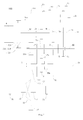
- the plurality of input shafts include a first input shaft 11 and a second input shaft 12.
- the second input shaft 12 may be hollow and the first input shaft 11 may be solid.
- One part of the first input shaft 11 may be inserted within the hollow second input shaft 12, and the other part of the first input shaft 11 may extend out of the second input shaft 12 along an axial direction of the second input shaft 12.
- the first input shaft 11 and the second input shaft 12 may be arranged coaxially.
- the first-third gear synchronizer 13c is disposed on the first output shaft 21 and between the first-gear driven gear 1b and the third-gear driven gear 3b.
- the first-third gear synchronizer 13c may engage the first-gear driven gear 1b with the first output shaft 21 or engage the third-gear driven gear 3b with the first output shaft 21, such that the shift driven gear may rotate synchronously with the corresponding output shaft, e.g. the first-gear driven gear 1b and the first output shaft 21 may rotate synchronously, and the third-gear driven gear 3b and the first output shaft 21 may rotate synchronously.
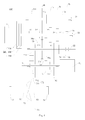
- the reverse idler gear 72, the middle idler 73 are positioned on the second output shaft 22
- the fifth-gear driven gear 5b is positioned on the second output shaft 22 and configured to solely engage the fifth-gear driven gear 5b with the second output shaft 22
- the reverse synchronizer 74c is configured to merely engage the middle idler 73 and the reverse idler gear 72.
- the reverse synchronizer 74c and the fifth gear synchronizer 5c may share a shift fork mechanism. Therefore, one shift fork mechanism is sufficient for the present disclosure, instead of tow shift fork mechanisms, i.e. one shift fork mechanism is saved, thus the structure of the power transmission system 100 can be more compact.
- the first motor generator 51 may output power and transmit the power to the second output shaft 22 via the synchronization of the motor synchronizer 33c (for example, synchronizing the second motor gear 32), and then the second output shaft 22 output the power to wheels of the vehicle, thus reversing the vehicle.
- the motor synchronizer 33c for example, synchronizing the second motor gear 32
- the differential 75 may be disposed between a pair of front wheels of the vehicle. In some embodiments, the differential 75 may be disposed between a pair of rear wheels of the vehicle. The differential 75 may allow the left and right driving wheels to roll with different angular speeds when the vehicle is turning or running on a rough road, , and therefore the left and right driving wheels of the vehicle may perform pure rolling motions on the ground.
- a shift driven gear 74 of a main reducer may be disposed on the differential 75, for example, the shift driven gear 74 may be disposed on a shell of the differential 75. In some embodiments, the shift driven gear 74 may be a bevel gear, without particular limits in the present disclosure.
- a first shift driven gear 211 is fixed on the first output shaft 21 and configured to rotate with the first output shaft 21 synchronously.
- the first shift driven gear 211 may mesh with the shift driven gear 74, thus transmitting power transmitted to the first output shaft 21 from the first output gear 211 to the shift driven gear 74 and the differential 75.
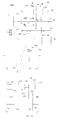
- the engine 4 in the parking-charging state, the engine 4 generates power and transmits the power to the second input shaft 12 via the dual clutch 2d.
- the motor synchronizer 33c may engage the motor power shaft 3 and the first motor gear 31, and therefore the power generated by the engine 4 may be transmitted to the motor power shaft 3 via the second input shaft 12, the middle idler 73, the first motor gear 31, and the motor synchronizer 33c sequentially.
- the motor power shaft 3 may transmit the power to the first motor generator 51, and the first motor generator 51 may be driven to generate electric power as a generator.
- the input terminal 23d is engaged with the first output terminal 21 d and engaged with the second output terminal 22d simultaneously, a part of power generated by the engine 4 may be output to one of the output shafts to drive the wheels of the vehicle, and the other part of power may be transmitted to the first motor generator 51 via the motor power shaft 3, thus driving the first motor generator 51 to generate electric power.
- a part of power generated by the engine 4 may be output from the first output shaft 21 or the second output shaft 22, such as via the first-gear gear pair, the third-gear gear pair or the fifth-gear gear pair.
- the other part of power generated by the engine 4 may be transmitted to the first motor generator 51 via the first motor gear 31, the motor synchronizer 33c, the motor power shaft 3 sequentially, thus driving the first motor generator 51 to generate electric power.
- a conventional dual clutch generally have two gear parts, and only one gear part is used when the dual clutch is working.
- two gears parts of the dual clutch 2d may be both engaged (for example, the input terminal 23d is engaged with the first output terminal 21d and engaged with the second output terminal 22d simultaneously) when the dual clutch 2d is working.
- a part of power from the engine 4 may be output to wheels of the vehicle via one output shaft to drive the vehicle to run, and the other part of power from the engine 4 may be transmitted to the first motor generator 51 to drive the first motor generator 51 to generate electric power. In this way, transmission modes of the vehicle are increased, and charging the vehicle while the vehicle is running may be achieved.
- the motor synchronizer 33c is disposed between the first motor gear 31 and the second motor gear 32, and therefore power generated by the first motor generator 51 may be selectively output via the first motor gear 31 or the second motor gear 32.
- the vehicle switches from outputting power via the first motor gear 31 to outputting power via the second motor gear 32 by the synchronization of the motor synchronizer 33c.
- the motor synchronizer 33c may engage the second motor gear 32 with the motor power shaft 3 rapidly, and therefore the synchronization time of the motor synchronizer 33c may be reduced and the transmission efficiency, the synchronization controllability and the synchronization real-time capability may be improved. In addition, the life of the motor synchronizer 33c may be prolonged and the maintenance cost of the vehicle may be reduced.
- the first motor generator 51 may adjust the rotating speed of the motor power shaft 3 based on the rotating speed of the first motor gear 31.
- the first motor generator 51 may increase or decrease the rotating speed of the motor power shaft 3 with the rotating speed of the first motor gear 31 as a target speed, such that the rotating speed of the motor power shaft 3 may be matched with the rotating speed of the first motor gear 31 in a shortest time, thus enhancing the engaging efficiency of the motor synchronizer 33c.
- the vehicle may run in an electric mode, i.e. the vehicle is driven by the first motor generator 51.
- the present disclosure is not limited to this embodiment.
- the motor synchronizer 33c may be switched from engaging with one of the first motor gear 31 and the second motor gear 32 to engaging with the other one of the first motor gear 31 and the second motor gear 32, the rotating speed of the motor power shaft 3 may be adjusted by the first motor generator 51.
- the first motor generator 51 may adjust the rotating speed of the motor power shaft 3, such that the rotating speed of the motor power shaft 3 may be matched with the rotating speed of the gear to be engaged, for example, the first motor gear 31 or the second motor gear 32.
- the first motor generator 51 may adjust the rotating speed of the motor power shaft 3 with the rotating speed of the gear to be engaged as a target speed, such that the rotating speed of the motor power shaft 3 may be matched with the rotating speed of the gear to be engaged in a shortest time, thus facilitating the engagement of the motor synchronizer 33c, significantly improving the transmission efficiency and reducing the transmission loss.
- the power transmission system 100 may include an electric differential lock unit.
- the electric differential lock unit may lock a pair of driving wheels when the vehicle is skidding, thus enhancing the antiskid performance and the trafficability performance of the vehicle.
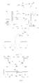
- the third motor generator 201 is configured to rotate together with one of the second pair of wheels 77.
- the third motor generator 201 may output power to this one wheel to drive this one wheel to rotate.
- power from this one wheel may be transmitted to the third motor generator 201, thus driving the third motor generator 201 to generate electric power.
- the third motor generator 201 and the fourth motor generator 301 may drive corresponding wheels respectively, such that the corresponding wheels may rotate at different rotating speeds, thus the object that different wheels rotates at different speeds may be achieved.
- the third motor generator 201 and the fourth motor generator 301 may drive the second pair of wheels 77 to rotate at a same rotating speed.
- the third motor generator 201 and the fourth motor generator 301 are provided and configured to drive the second pair of wheels 77 respectively, and therefore having the second pair of wheels 77 rotating at different rotating speeds may be achieved.
- the antiskid synchronizer 503 may synchronize the second pair of wheels 77 such that the second pair of wheels 77 rotate synchronously.
- powers output by two motors for example, the third motor generator 201 and the fourth motor generator 301) or one motor (for example, one of the third motor generator 201 and the fourth motor generator 301) may be coupled to drive the second pair of wheels 77 together, thus enhancing the antiskid capability and trafficability performance of the vehicle.
- the power transmission system 100 includes the antiskid synchronizer 503, and therefore a mechanical self-locking differential mechanism commonly used in an axle (such as a rear axle) a conventional power transmission system may be avoided.
- a mechanical self-locking differential mechanism commonly used in an axle (such as a rear axle) a conventional power transmission system may be avoided.
- the functions of a mechanical self-locking differential mechanism are performed by the antiskid synchronizer 503, and therefore the power transmission system 100 according to embodiments of the present disclosure may have a more compact structure and relatively lower cost.
- the third motor generator 201, the fourth motor generator 301, and transmission method thereof will be described below in detail with references to Figs. 5-12 .
- the third motor generator 201 may perform power transmission with the corresponding wheel via a gear mechanism.
- the fourth motor generator 301 may perform power transmission with the corresponding wheel via a gear mechanism.
- the gear mechanism has simple structure and is convenient for use in power transmission.
- a desired transmission ration may be obtained and the power transmission may be reliable.
- the third motor generator 201 and the fourth motor generator 301 may perform power transmission with corresponding wheel(s) via a same gear mechanism.
- the gear mechanism is common, and the power transmission system 100 may be highly symmetric, thus avoiding the center of gravity moving to one side. With one common gear mechanism, the center of gravity may be located right in the middle or substantially the middle of the two wheels, and both the stability and reliability of the power transmission system 100 may be improved.
- the gear mechanism between the third motor generator 201 and the corresponding wheel may include a first gear 401, a second gear 402, a third gear 403, and a fourth gear 404.
- the first gear 401 may be disposed on the first power output shaft 202 corresponding to the third motor generator 201, and the first gear 401 is configured to rotate synchronously with the first power output shaft 202.
- the first power output shaft 202 may output power generated by the third motor generator 201.
- the first power output shaft 202 may transmit power generated by the corresponding wheel to the third motor generator 201.
- the first power output shaft 202 and the third motor generator 201 may share a same motor shaft.
- the motor shaft of the first power output shaft 202 and the motor shaft the third motor generator 201 may be two individual parts different from each other. In the present embodiment, the motor shaft of the first power output shaft 202 and the motor shaft the third motor generator 201 may be connected to each other.
- a first drive shaft 204 is connected with a wheel corresponding to the third motor generator 201, and the second gear 402 is disposed on the first drive shaft 204 and configured to rotate synchronously with the first drive shaft 204.
- the third gear 403 and the first gear 401 are configured to mesh with each other, and the fourth gear 404 and the second gear 402 are configured to mesh with each other.
- the third gear 403 and the fourth gear 404 are coaxially arranged and may rotate synchronously.
- the gear mechanism between the fourth motor generator 301 and the corresponding wheel may include a fifth gear 405, a sixth gear 406, a seventh gear 407, and an eighth gear 408.
- the fifth gear 405 may be disposed on the second power output shaft 302 corresponding to the fourth motor generator 301, and the fifth gear 405 is configured to rotate synchronously with the second power output shaft 302.
- the second power output shaft 302 may output power generated by the fourth motor generator 301.
- the second power output shaft 302 may transmit power generated by the corresponding wheel to the fourth motor generator 301.
- the second power output shaft 302 and the fourth motor generator 301 may share a same motor shaft.
- the motor shaft of the second power output shaft 302 and the motor shaft the fourth motor generator 301 may be two individual parts different from each other.
- the motor shaft of the second power output shaft 302 and the motor shaft the fourth motor generator 301 may be connected to each other.
- a second drive shaft 304 is connected with a wheel corresponding to the fourth motor generator 301, and the sixth gear 406 is disposed on the second drive shaft 304 and configured to rotate synchronously with the second drive shaft 304.
- the seventh gear 407 and the fifth gear 405 are configured to mesh with each other, and the eighth gear 408 and the sixth gear 406 are configured to mesh with each other.
- the seventh gear 407 and the eighth gear 408 are coaxially arranged and may rotate synchronously.
- the first gear 401 and the fifth gear 405 may have a same structure, such as having a same size and a same teeth number.
- the second gear 402 and the sixth gear 406 may have the same structure, such as having a same size and a same teeth number.
- the third gear 403 and the seventh gear 407 may have the same structure, such as having a same size and a same teeth number.
- the fourth gear 404 and the eighth gear 408 may have the same structure, such as having a same size and a same teeth number. Therefore, versatility of the gear mechanism may be improved.
- the antiskid synchronizer 503 may be disposed on the first drive shaft 204 and configured to selectively engage with the sixth gear 406.
- a gear ring may be provided on a side of the sixth gear 406 facing the antiskid synchronizer 503, and the antiskid synchronizer 503 may include an engaging sleeve to adapt to the gear ring. With the engagement of the antiskid synchronizer 503, the second pair of wheels 77 may rotate synchronously.
- the antiskid synchronizer 503 may be disposed on the first power output shaft 202 and configured to selectively engage with the fifth gear 405.
- a gear ring may be provided on a side of the fifth gear 405 facing the antiskid synchronizer 503, and the antiskid synchronizer 503 may include an engaging sleeve to adapt to the gear ring. With the engagement of the antiskid synchronizer 503, the second pair of wheels 77 may rotate synchronously.
- the antiskid synchronizer 503 may be disposed on the first power output shaft 202 corresponding to the third motor generator 201, and configured to selectively engage with the second power output shaft 302 corresponding to the fourth motor generator 301. With the engagement of the antiskid synchronizer 503, the second pair of wheels 77 may rotate synchronously.
- the power transmission system 100 and the conditions of the power transmission system 100 will be described below with reference to Figs. 2-12 .
- the second input shaft 12 may be a hollow shaft, and the first input shaft 11 may be a solid shaft.
- the second input shaft 12 is coaxially fitted over the first input shaft 11, and a part of the first input shaft 11 extends outside of the second input shaft 12 along an axial direction of the second input shaft 12.
- the second-gear driving gear 2a and the fourth-gear driving gear 4a are disposed on the second input shaft 12 and configured to rotate synchronously with the second input shaft 12, and the second-gear driving gear 2a is positioned on the left side and the fourth-gear driving gear 4a is positioned on the right side.
- the first output shaft 21 is arranged parallel to the two input shafts, i.e. the first and second input shafts 11, 12.
- the first-gear driven gear 1b, the second-gear driven gear 2b, the third-gear driven gear 3b and the fourth-gear driven gear 4b are freely fitted over the first output shaft 21.
- the first-gear driven gear 1b is configured to mesh directly with the first-gear driving gear 1a
- the second-gear driving gear 2a is configured to mesh directly with the second-gear driven gear 2b
- the third-gear driving gear 3a is configured to mesh directly with the third-gear driven gear 3b
- the fourth-gear driving gear 4a is configured to mesh directly with the fourth-gear driven gear 4b.
- the second output shaft 22 is arranged parallel to the two input shafts, i.e. the first and second input shafts 11, 12.
- the fifth-gear driven gear 5b is freely fitted over the second output shaft 22 and configured to directly mesh with the fifth-gear driving gear 5a.
- the fifth-gear synchronizer 5c is disposed on the second output shaft 22 and configured to synchronize the fifth-gear driven gear 5b and the second output shaft 22.
- the transmission gear 6 is disposed on the second output shaft 22 and configured to rotate synchronously with the second output shaft 22, and the reverse idler gear 72 is freely fitted over the second output shaft 22.
- the transmission gear 6 is configured to directly mesh with the second output shaft 22.
- the reverse idler gear 72 includes a gear sleeve 721 at one side thereof, and the gear sleeve 721 is freely fitted over the second output shaft 22.
- the middle idler 73 is freely fitted over the gear sleeve 721 and configured to mesh with the second-gear driving gear 2a and the first motor gear 31 respectively.
- the reverse synchronizer 74c is arranged on the gear sleeve 721 and configured to engage with the middle idler 73.
- the speed ratio relates to parameters such as the rotating speed of the engine 4 in the parking state, the type of the first motor generator 51, and maximum rotating speed acceptable by the peripheral parts such as bearings, and so on.
- the speed ratio may be designed according to the above parameters and the power transmission ratio may be flexibly designed, thus making maximum use of the power from the engine 4 and achieving the object of quick charging.
- the motor synchronizer 33c engages the second motor gear 32, and power output by the first motor generator 51 is transmitted to the second output shaft 22 via the second motor gear 32 and the transmission gear 6, and then output from the second output shaft 22.
- the motor synchronizer 33c moves from an engaging position at the second motor gear 32 to an engaging position at the first motor gear 31.
- the first motor generator 51 may adjust the rotating speed of the motor power shaft 3 with the rotating speed of the first motor gear 31 as a target speed. In this way, the rotating speed of the motor power shaft 3 is matched with the rotating speed of the first motor gear 31, and thereby the motor synchronizer 33c may engage with the first motor gear 31 rapidly. Thus the synchronization efficiency is improved.
- the speed adjusting mode described above may be used in other conditions, such as in a hybrid condition, provided change of the engaging state of the motor synchronizer 33c is related.
- the above speed adjusting mode may be used in a condition in which the motor synchronizer 33c changes from engaging with the first motor gear 31 to engaging with the second motor gear 32.
- the above speed adjusting mode may be used in a condition in which the motor synchronizer 33c changes from engaging with the second motor gear 32 to engaging with the first motor gear 31.
- the first motor generator 51 When the power transmission system 100 is operated in the pure electric condition, the first motor generator 51 functions as a motor and can rotate along a predetermined rotating direction, such as the clockwise direction.
- the first motor generator 51 may adjust the speed, such that the shift driven gear 74 may synchronously receive the first power from the engine 4 and the second power from the first motor generator 51, thus ensuring a smooth power transmission.
- the second-fourth gear synchronizer 24c is engaged with the second-gear driven gear 2b
- the input terminal 23d of the dual clutch 2d is engaged with the second output terminal 22d and disengaged from the first output terminal 21d
- the motor synchronizer 33c is engaged with the second motor gear 32.
- First power output by the engine 4 is transmitted to the first output shaft 21 via the second input shaft 12 and the second-gear gear pair
- second power output by the first motor generator 51 is transmitted to the second output shaft 22 via the second motor gear 32 and the transmission gear 6.
- the first power and the second power are coupled at the driven gar 74, and then distributed to wheels by the differential 75.
- the first motor generator 51 may adjust the speed, such that the shift driven gear 74 may synchronously receive the first power from the engine 4 and the second power from the first motor generator 51, thus ensuring a smooth power transmission.
- the first motor generator 51 may adjust the speed, such that the second output shaft 22 may synchronously receive the first power from the engine 4 and the second power from the first motor generator 51, thus ensuring a smooth power transmission.
Landscapes
- Engineering & Computer Science (AREA)
- Mechanical Engineering (AREA)
- Chemical & Material Sciences (AREA)
- Combustion & Propulsion (AREA)
- Transportation (AREA)
- General Engineering & Computer Science (AREA)
- Structure Of Transmissions (AREA)
- Hybrid Electric Vehicles (AREA)
Applications Claiming Priority (2)
| Application Number | Priority Date | Filing Date | Title |
|---|---|---|---|
| CN201420518258.6U CN204323055U (zh) | 2014-09-10 | 2014-09-10 | 变速器、动力传动系统及车辆 |
| CN201410460546.5A CN104608621B (zh) | 2014-09-10 | 2014-09-10 | 变速器、动力传动系统及车辆 |
Publications (2)
| Publication Number | Publication Date |
|---|---|
| EP2995489A1 true EP2995489A1 (de) | 2016-03-16 |
| EP2995489B1 EP2995489B1 (de) | 2020-01-22 |
Family
ID=52705998
Family Applications (1)
| Application Number | Title | Priority Date | Filing Date |
|---|---|---|---|
| EP15158701.1A Active EP2995489B1 (de) | 2014-09-10 | 2015-03-11 | Übertragungseinheit, leistungsübertragungssystem und fahrzeug damit |
Country Status (3)
| Country | Link |
|---|---|
| US (1) | US9568065B2 (de) |
| EP (1) | EP2995489B1 (de) |
| WO (1) | WO2016037469A1 (de) |
Families Citing this family (11)
| Publication number | Priority date | Publication date | Assignee | Title |
|---|---|---|---|---|
| WO2017023854A1 (en) | 2015-07-31 | 2017-02-09 | Massachusetts Institute Of Technology | Clutchless shifting of a manual transmission |
| WO2017121813A1 (en) * | 2016-01-12 | 2017-07-20 | Dana Belgium N.V. | Dual clutch transmission with a reverse countershaft |
| WO2017192913A1 (en) * | 2016-05-04 | 2017-11-09 | Massachusetts Institute Of Technology | Dual-shaft clutchless hybrid transmission |
| CN106763552A (zh) * | 2017-03-17 | 2017-05-31 | 苏州绿控传动科技有限公司 | 一种双电机驱动结构 |
| CN110005789B (zh) * | 2018-01-04 | 2022-07-12 | 上汽通用汽车有限公司 | 混合动力变速箱电机输入轴系结构 |
| CN109109647B (zh) * | 2018-09-29 | 2024-08-09 | 株洲齿轮有限责任公司 | 混合动力汽车及其混合动力驱动总成 |
| DE102019212145A1 (de) * | 2019-08-13 | 2021-02-18 | Zf Friedrichshafen Ag | Getriebeanordnung, Hybrid-Getriebeanordnung, Hybrid-Antriebsstrang sowie Kraftfahrzeug |
| CN113685506B (zh) * | 2020-05-18 | 2024-03-22 | 广州汽车集团股份有限公司 | 十挡双离合变速器及车辆 |
| CN114559803B (zh) * | 2022-03-18 | 2025-09-23 | 重庆理工大学 | 混合动力汽车动力耦合传动系统、实现方法及汽车 |
| CN116587830A (zh) * | 2023-06-27 | 2023-08-15 | 南京邦奇自动变速箱有限公司 | 车辆混合动力机构 |
| CN121403988A (zh) * | 2025-12-30 | 2026-01-27 | 麦格纳动力总成(江西)有限公司 | 一种电动驱动系统及车辆 |
Citations (5)
| Publication number | Priority date | Publication date | Assignee | Title |
|---|---|---|---|---|
| JPH0993714A (ja) * | 1995-09-20 | 1997-04-04 | Mitsubishi Motors Corp | 電気自動車の駆動装置 |
| DE10239540A1 (de) * | 2001-07-15 | 2004-03-11 | Boisch, Richard, Prof. Dr. | Rückwärtsgang und Zentralsynchronisierung für Lastschaltgetriebe |
| DE102008002381A1 (de) * | 2008-06-12 | 2009-12-17 | Zf Friedrichshafen Ag | Hybridantriebsstrang für ein Kraftfahrzeug und Verfahren zum Betreiben des Hybridantriebsstrangs |
| EP2390127A1 (de) * | 2010-05-31 | 2011-11-30 | Byd Company Limited | Hybridantriebssystem und Fahrzeug damit |
| DE102011086743A1 (de) * | 2011-11-21 | 2013-05-23 | Schaeffler Technologies AG & Co. KG | Elektromechanische Fahrzeugantriebseinrichtung |
Family Cites Families (139)
| Publication number | Priority date | Publication date | Assignee | Title |
|---|---|---|---|---|
| US4132133A (en) | 1976-12-20 | 1979-01-02 | Allis-Chalmers Corporation | Auxiliary transmission |
| US4610177A (en) | 1985-02-25 | 1986-09-09 | General Motors Corporation | Preselected multiratio transmission |
| US4676115A (en) | 1985-05-13 | 1987-06-30 | Eaton Corporation | Semi-automatic transmission |
| JPS6343856A (ja) | 1986-08-08 | 1988-02-24 | Mazda Motor Corp | 自動車のスリツプ制御装置 |
| US5586613A (en) | 1993-04-22 | 1996-12-24 | The Texas A&M University System | Electrically peaking hybrid system and method |
| DE19631983C1 (de) | 1996-08-08 | 1998-02-12 | Volkswagen Ag | Verfahren zum Schalten eines Doppelkupplungsgetriebes und Doppelkupplungsgetriebe mit Synchronisiereinrichtung |
| EP1038346A2 (de) | 1997-10-21 | 2000-09-27 | Stridsberg Innovation Ab | Hybridantrieb |
| US7252020B2 (en) | 2000-01-10 | 2007-08-07 | The United States Of America As Represented By The Administrator Of The U.S. Environmental Protection Agency | Vehicle drive-train including a clutchless transmission, and method of operation |
| JP3706290B2 (ja) | 2000-02-04 | 2005-10-12 | 株式会社日立製作所 | ハイブリッド自動車の制御装置 |
| DE10133695B4 (de) | 2000-07-18 | 2015-08-13 | Schaeffler Technologies AG & Co. KG | Doppelkuplungsgetriebe |
| US6490945B2 (en) | 2001-01-10 | 2002-12-10 | New Venture Gear, Inc. | Twin clutch automated transmission with integrated transfer case |
| DE10209514B4 (de) | 2001-03-30 | 2016-06-09 | Schaeffler Technologies AG & Co. KG | Antriebsstrang |
| US7223200B2 (en) | 2001-10-22 | 2007-05-29 | Toyota Jidosha Kabushiki Kaisha | Hybrid-vehicle drive system and operation method with a transmission |
| JP4147850B2 (ja) | 2002-02-15 | 2008-09-10 | 日産自動車株式会社 | 制動制御装置 |
| US20030183467A1 (en) | 2002-03-28 | 2003-10-02 | Ford Global Technologies, Inc. | Placement of an auxilliary mass damper to eliminate torsional resonances in driving range in a parallel-series hybrid system |
| CN2602978Y (zh) | 2002-08-14 | 2004-02-11 | 同济大学新能源汽车工程中心 | 汽车电子稳定控制系统 |
| JP3676336B2 (ja) | 2002-10-02 | 2005-07-27 | 本田技研工業株式会社 | ハイブリッド車両の出力制御装置 |
| JP2005001466A (ja) * | 2003-06-10 | 2005-01-06 | Honda Motor Co Ltd | ハイブリッド車両 |
| JP3864950B2 (ja) | 2003-11-18 | 2007-01-10 | 日産自動車株式会社 | ハイブリッド変速機 |
| KR100634589B1 (ko) | 2003-12-24 | 2006-10-13 | 현대자동차주식회사 | 하이브리드 전기자동차용 이중 클러치 변속기 및 그모드별 작동방법 |
| CN2716053Y (zh) | 2004-02-27 | 2005-08-10 | 周飞 | 汽车混合动力驱动机构 |
| DE112005000758A5 (de) | 2004-04-16 | 2008-06-26 | Avl List Gmbh | Verfahren zur Steuerung des Anfahrvorganges eines Kraftfahrzeuges |
| JP4069901B2 (ja) | 2004-05-20 | 2008-04-02 | トヨタ自動車株式会社 | ハイブリッド車のドライブトレーン |
| JP4453468B2 (ja) | 2004-07-16 | 2010-04-21 | 日産自動車株式会社 | 先行車追従走行制御装置 |
| JP4569493B2 (ja) | 2005-06-06 | 2010-10-27 | 日産自動車株式会社 | ハイブリッド車両のオイルポンプ駆動制御装置 |
| JP2007118751A (ja) | 2005-10-27 | 2007-05-17 | Toyota Motor Corp | 動力出力装置、それを搭載した車両及び動力出力装置の制御方法 |
| JP4341610B2 (ja) | 2005-11-09 | 2009-10-07 | 日産自動車株式会社 | ハイブリッド車両のエンジン再始動制御装置 |
| DE102005063248B4 (de) | 2005-12-21 | 2010-09-30 | Getrag Getriebe- Und Zahnradfabrik Hermann Hagenmeyer Gmbh & Cie Kg | Doppelkupplungsanordnung |
| CN101516708B (zh) | 2006-09-15 | 2012-07-04 | 舍弗勒技术股份两合公司 | 用来运行用于机动车的混合动力总成系统的方法 |
| JP4562195B2 (ja) | 2006-09-20 | 2010-10-13 | 三菱ふそうトラック・バス株式会社 | ハイブリッド電気自動車の変速制御装置 |
| US7691026B2 (en) | 2006-11-17 | 2010-04-06 | Gm Global Technology Operations, Inc. | Control architecture for optimization and control of a hybrid powertrain system |
| CN101535075A (zh) | 2006-12-08 | 2009-09-16 | 比亚迪股份有限公司 | 混合动力输出装置 |
| CN101209666A (zh) | 2006-12-25 | 2008-07-02 | 比亚迪股份有限公司 | 混合动力输出装置 |
| CN101209675B (zh) | 2006-12-26 | 2010-05-19 | 比亚迪股份有限公司 | 电动汽车能量回馈控制方法 |
| US20100145589A1 (en) | 2007-04-24 | 2010-06-10 | Mitsubishi Electric Corporation | Electric Drive System and Hybrid Drive System |
| KR100887797B1 (ko) | 2007-09-28 | 2009-03-09 | 현대자동차주식회사 | 하이브리드 차량의 오토크루즈 주행 제어 방법 |
| US8408342B2 (en) | 2007-10-22 | 2013-04-02 | BYD Company Ltd. | Hybrid power driving system and driving method thereof |
| US8594867B2 (en) | 2007-11-04 | 2013-11-26 | GM Global Technology Operations LLC | System architecture for a blended braking system in a hybrid powertrain system |
| CN101450607B (zh) | 2007-12-03 | 2014-04-02 | 比亚迪股份有限公司 | 混合动力驱动系统及其驱动方法 |
| CN201214410Y (zh) | 2007-12-29 | 2009-04-01 | 桂林吉星电子等平衡动力有限公司 | 一种油电混合动力电动车的速度巡航控制装置 |
| WO2009086700A1 (zh) | 2008-01-08 | 2009-07-16 | Guilin Geely Stars Oil-Electric Hybrid Engine Co., Ltd. | 一种油电混合动力电动车的速度巡航控制装置和方法 |
| CN101980881B (zh) | 2008-03-27 | 2013-12-18 | 力至优三菱叉车株式会社 | 混合动力工业车辆 |
| CN101983150B (zh) | 2008-03-31 | 2013-05-29 | 爱信Ai株式会社 | 混合动力装置 |
| JP4942212B2 (ja) | 2008-04-21 | 2012-05-30 | アイシン・エーアイ株式会社 | ハイブリッド動力装置 |
| CN101659203A (zh) | 2008-08-28 | 2010-03-03 | 比亚迪股份有限公司 | 一种混合动力驱动系统及其驱动方法 |
| CN101380887B (zh) | 2008-10-23 | 2012-11-07 | 上海交通大学 | 含有驱动电机工作模式切换装置的混合动力轿车驱动系统 |
| US8523734B2 (en) | 2008-11-07 | 2013-09-03 | Ricardo, Inc. | Multi-mode hybrid transmission |
| CN101407179B (zh) | 2008-11-28 | 2011-01-26 | 清华大学 | 有防抱死制动功能的混合制动系统及控制方法 |
| CN102348568B (zh) | 2009-03-30 | 2014-06-25 | 本田技研工业株式会社 | 混合动力车辆用动力传递装置 |
| US8505400B2 (en) | 2009-04-02 | 2013-08-13 | GM Global Technology Operations LLC | Dual clutch five speed transmission |
| CN201390137Y (zh) | 2009-04-22 | 2010-01-27 | 重庆恒通客车有限公司 | 前置后驱气电混合动力客车 |
| CN101549634A (zh) | 2009-05-14 | 2009-10-07 | 上海交通大学 | 多模式无级变速混联式混合动力系统 |
| EP2478257B1 (de) | 2009-09-14 | 2014-07-16 | Mack Trucks, Inc. | Mehrfachkupplungsgetriebe |
| EP2474434B1 (de) | 2009-10-05 | 2018-06-20 | Honda Motor Co., Ltd. | Fahrzeugantriebsvorrichtung |
| CN201511806U (zh) | 2009-10-19 | 2010-06-23 | 重庆恒通客车有限公司 | 同轴并联式油电/气电混合动力客车三类底盘 |
| JP4877382B2 (ja) | 2009-11-20 | 2012-02-15 | トヨタ自動車株式会社 | ハイブリッド自動車およびその制御方法 |
| US8251850B2 (en) | 2009-11-30 | 2012-08-28 | GM Global Technology Operations LLC | Strong two-mode hybrid powertrain with two motor/generators |
| CN102085795B (zh) | 2009-12-04 | 2015-04-15 | 上海汽车集团股份有限公司 | 一种车用离合器动力藕合同步器换档混合动力驱动系统 |
| DE112010004705T5 (de) | 2009-12-08 | 2013-01-17 | Honda Motor Co., Ltd. | Hybridfahrzeug |
| BR112012014767B1 (pt) | 2009-12-16 | 2021-02-23 | Honda Motor Co., Ltd | veículo híbrido e método de controle do mesmo |
| WO2011078189A1 (ja) | 2009-12-22 | 2011-06-30 | 本田技研工業株式会社 | ハイブリッド車両の制御装置 |
| WO2011086801A1 (ja) | 2010-01-18 | 2011-07-21 | 日立建機株式会社 | 作業用車両の駆動制御装置 |
| JP5273069B2 (ja) | 2010-03-02 | 2013-08-28 | アイシン精機株式会社 | ハイブリッド駆動装置 |
| DE112011101150T5 (de) | 2010-03-31 | 2013-01-31 | Honda Motor Co., Ltd. | Hybridfahrzeug |
| JP2011218836A (ja) | 2010-04-02 | 2011-11-04 | Toyota Motor Corp | 車両用ハイブリッド駆動装置 |
| US8425377B2 (en) | 2010-04-27 | 2013-04-23 | Ford Global Technologies, Llc | Multiple-mode power split hybrid powertrain |
| EP2385270B1 (de) | 2010-05-03 | 2012-05-23 | C.R.F. Società Consortile per Azioni | Hybrid Antriebssystem für Kraftfahrzeug mit doppelter Schalttrommel |
| GB201007566D0 (en) | 2010-05-06 | 2010-06-23 | Agco Sa | Tractor with hybrid power system |
| DE102010028935A1 (de) | 2010-05-12 | 2011-11-17 | Zf Friedrichshafen Ag | Verfahren zum Betreiben eines Antriebsstrangs |
| CN102259584B (zh) | 2010-05-31 | 2014-07-02 | 比亚迪股份有限公司 | 混合动力驱动系统及包含该驱动系统的车辆 |
| CN201777113U (zh) * | 2010-05-31 | 2011-03-30 | 比亚迪股份有限公司 | 混合动力驱动系统及具有该系统的车辆 |
| US8647231B2 (en) | 2010-07-07 | 2014-02-11 | Ford Global Technologies, Llc | Transitioning between electric-drive and parallel-drive in a hybrid-electric vehicle powertrain |
| CN102343824B (zh) | 2010-07-30 | 2013-07-10 | 北汽福田汽车股份有限公司 | 电动车制动能量回收控制方法及其装置 |
| CN102371893A (zh) | 2010-08-13 | 2012-03-14 | 上海捷能汽车技术有限公司 | 车辆用电驱动变速装置 |
| CN101947915B (zh) | 2010-09-03 | 2013-01-02 | 中国汽车技术研究中心 | 一种强混合动力汽车工作模式切换中发动机起停控制方法 |
| CN101973260B (zh) | 2010-09-25 | 2012-09-19 | 徐工集团工程机械股份有限公司江苏徐州工程机械研究院 | 液压混合动力车辆制动转矩控制方法 |
| CN202242966U (zh) | 2010-09-26 | 2012-05-30 | 比亚迪股份有限公司 | 电动车辆的驱动系统 |
| CN201849308U (zh) | 2010-09-30 | 2011-06-01 | 长城汽车股份有限公司 | 汽车混合动力系统 |
| CN101973207B (zh) | 2010-09-30 | 2015-05-27 | 长城汽车股份有限公司 | 一种混合动力汽车变速器 |
| CN201849307U (zh) | 2010-09-30 | 2011-06-01 | 长城汽车股份有限公司 | 汽车混合动力系统 |
| JP5201190B2 (ja) | 2010-10-08 | 2013-06-05 | 三菱自動車工業株式会社 | ハイブリット車のクラッチ制御装置 |
| DE102011115780A1 (de) | 2010-10-15 | 2012-04-19 | Gm Global Technology Operations Llc (N.D.Ges.D. Staates Delaware) | Hydraulisches Steuersystem für Vollhybridfahrzeuge auf der Basis eines elektromechanischen Mikrosystems (MEMS) |
| DE112011103538T5 (de) | 2010-10-21 | 2013-07-25 | Honda Motor Co., Ltd. | Antriebsvorrichtung für Hybridfahrzeug |
| EP2631103B1 (de) | 2010-10-22 | 2021-03-10 | Nissan Motor Co., Ltd | Regenerative bremssteuerungsvorrichtung für ein fahrzeug |
| CN201872594U (zh) * | 2010-11-15 | 2011-06-22 | 同济大学 | 混合动力车辆动力传动装置 |
| CN102009587B (zh) | 2010-11-19 | 2012-11-14 | 中国汽车技术研究中心 | 基于电控机械式变速器的混合动力装置 |
| CN102030005B (zh) | 2010-12-10 | 2013-07-03 | 上海中科深江电动车辆有限公司 | 电动汽车惯性滑行状态下的自动式机械变速器控制方法 |
| CN201907400U (zh) | 2010-12-20 | 2011-07-27 | 浙江吉利汽车研究院有限公司 | 并联混合动力驱动系统 |
| CN103298637B (zh) | 2011-02-08 | 2016-03-30 | 本田技研工业株式会社 | 混合动力车辆的驱动装置 |
| JP2012187962A (ja) | 2011-03-09 | 2012-10-04 | Toyota Motor Corp | 車両制御装置 |
| DE102011005451A1 (de) | 2011-03-11 | 2012-09-13 | Zf Friedrichshafen Ag | Hybridantrieb eines Kraftfahrzeugs und Verfahren zur Steuerung eines Hybridantriebs |
| CN102303517B (zh) | 2011-06-23 | 2014-03-19 | 苏州安远新能源动力有限公司 | 采用同步器实现模式切换的增程式混合动力汽车动力系统 |
| ITPD20110252A1 (it) | 2011-07-22 | 2013-01-23 | Mecaprom Technologies Corp I Talia Srl A So | Veicolo a propulsione ibrida |
| JP2013032119A (ja) | 2011-08-02 | 2013-02-14 | Honda Motor Co Ltd | ハイブリッド駆動装置 |
| CN102381178B (zh) | 2011-08-24 | 2014-07-02 | 奇瑞汽车股份有限公司 | 插电式混合动力汽车动力系统及其再生制动控制方法 |
| JP5720893B2 (ja) | 2011-09-01 | 2015-05-20 | 三菱自動車工業株式会社 | ハイブリット車両の制御装置 |
| US8771138B2 (en) | 2011-09-16 | 2014-07-08 | Eaton Corporation | Hybrid hydraulic drive system architecture |
| CN103029558A (zh) | 2011-09-30 | 2013-04-10 | 比亚迪股份有限公司 | 一种混合动力系统及包括该系统的车辆 |
| CN202345366U (zh) | 2011-11-18 | 2012-07-25 | 同济大学 | 一种采用双同步器的模块化混合动力电动汽车动力系统 |
| CN202319868U (zh) | 2011-11-18 | 2012-07-11 | 同济大学 | 采用同步器和离合器的模块化混合动力电动汽车动力系统 |
| CN202319954U (zh) | 2011-11-18 | 2012-07-11 | 同济大学 | 采用惯性同步器电机模块的双电机动力耦合驱动装置 |
| JP2013112073A (ja) | 2011-11-25 | 2013-06-10 | Daimler Ag | ハイブリッド自動車の制御装置 |
| CN102490588B (zh) | 2011-12-02 | 2013-12-11 | 吉林大学 | 基于机械自动变速器的插电式混合动力驱动装置 |
| CN102678839B (zh) | 2011-12-08 | 2015-05-13 | 河南科技大学 | 一种拖拉机中使用的双离合器变速器 |
| JP5856465B2 (ja) | 2011-12-16 | 2016-02-09 | トヨタ自動車株式会社 | 車両 |
| CN202429065U (zh) | 2011-12-30 | 2012-09-12 | 比亚迪股份有限公司 | 电动车辆及其驱动系统 |
| CN103183026B (zh) | 2011-12-31 | 2016-01-13 | 上海汽车集团股份有限公司 | 一种混合动力车辆的能量回馈控制方法 |
| CN102555766B (zh) | 2012-01-10 | 2014-11-26 | 重庆青山工业有限责任公司 | 一种混合动力变速器总成 |
| JP2013169831A (ja) | 2012-02-18 | 2013-09-02 | Honda Motor Co Ltd | ハイブリット車両 |
| US9181895B2 (en) | 2012-03-01 | 2015-11-10 | Johnson Controls Technology Company | Start-stop retrofit systems and methods |
| CN102582413A (zh) * | 2012-03-06 | 2012-07-18 | 韩荣辉 | 混合动力车 |
| CN102555769B (zh) | 2012-03-12 | 2014-12-10 | 重庆大学 | 一种混联式双电机多工作模式混合动力驱动总成 |
| DE102012204719A1 (de) | 2012-03-23 | 2013-09-26 | Zf Friedrichshafen Ag | Verfahren zum Betreiben eines Antriebsstrangs eines Fahrzeugs mit Parallel-Hybrid-Antrieb |
| CN102642474B (zh) | 2012-04-12 | 2014-04-09 | 清华大学 | 基于加速踏板及制动踏板的电驱动汽车回馈制动控制方法 |
| CN102678871A (zh) | 2012-05-09 | 2012-09-19 | 北京汽车新能源汽车有限公司 | 一种用于电动车的三离合变速器装置及电动车 |
| CN202656855U (zh) | 2012-05-11 | 2013-01-09 | 北京智行鸿远汽车技术有限公司 | 一种单轴并联混合动力系统 |
| CN102673382A (zh) | 2012-05-16 | 2012-09-19 | 同济大学 | 轮边动力混合的驱动系统 |
| JP5899047B2 (ja) | 2012-05-18 | 2016-04-06 | 本田技研工業株式会社 | ハイブリッド車両の制御装置及び制御方法 |
| CN102673365A (zh) | 2012-06-01 | 2012-09-19 | 同济大学 | 采用同步带传动的混合动力电动汽车驱动系统 |
| CN202641355U (zh) | 2012-06-12 | 2013-01-02 | 福建省福工动力技术股份公司 | 具有停车熄火功能的混联式混合动力系统 |
| CN102975607A (zh) | 2012-11-02 | 2013-03-20 | 同济大学 | 以非对称式行星锥齿轮机构作为动力耦合装置的混合动力汽车驱动和传动系统 |
| JP2014091428A (ja) * | 2012-11-05 | 2014-05-19 | Aisin Ai Co Ltd | ハイブリッド車の動力伝達装置 |
| US8801566B2 (en) | 2012-11-08 | 2014-08-12 | Gm Global Technology Operations, Llc | Quad-clutch multi-speed transmission |
| DE102012221889A1 (de) | 2012-11-29 | 2014-06-05 | Zf Friedrichshafen Ag | Zugkraftunterstütztes Mehrgruppengetriebe |
| KR101362059B1 (ko) | 2012-12-10 | 2014-02-12 | 현대자동차 주식회사 | 더블 클러치 변속기 |
| DE102013201744A1 (de) | 2013-02-04 | 2014-08-07 | Zf Friedrichshafen Ag | Hybridisiertes Kraftfahrzeuggetriebe |
| CN103144528B (zh) | 2013-02-20 | 2015-10-07 | 上海中科深江电动车辆有限公司 | 应用于混合动力汽车的双离合变速器及其使用方法 |
| CN203283020U (zh) | 2013-04-28 | 2013-11-13 | 长城汽车股份有限公司 | 混合动力变速器及相应的车辆 |
| CN203305832U (zh) | 2013-05-14 | 2013-11-27 | 北汽福田汽车股份有限公司 | 用于混合动力车辆的双离合自动变速器和混合动力车辆 |
| CN105346370B (zh) | 2013-07-17 | 2017-10-03 | 合肥工业大学 | 一种油电混合动力扫路车用动力耦合器的控制方法 |
| CN103527726B (zh) | 2013-10-14 | 2016-02-24 | 谢晋 | 变速器 |
| CN203516615U (zh) | 2013-10-14 | 2014-04-02 | 谢晋 | 变速器 |
| CN103697118A (zh) | 2013-12-26 | 2014-04-02 | 天津市松正电动汽车技术股份有限公司 | 多用变速器 |
| CN103832263B (zh) | 2014-02-26 | 2016-09-07 | 长城汽车股份有限公司 | 用于车辆的动力传动系统及具有其的车辆 |
| CN103912640A (zh) | 2014-04-09 | 2014-07-09 | 天津天海同步科技股份有限公司 | 电动车用两挡自动变速器 |
| CN103921674A (zh) | 2014-04-19 | 2014-07-16 | 诸暨市中汽机械零部件有限公司 | 一种电动汽车用变速箱 |
| CN203876574U (zh) | 2014-06-04 | 2014-10-15 | 合肥工业大学 | 一种两挡电动汽车的动力系统总成 |
| CN203962884U (zh) | 2014-06-04 | 2014-11-26 | 上海通用汽车有限公司 | 用于混合动力车的双离合变速器系统及装设其的汽车 |
| CN204095490U (zh) | 2014-07-31 | 2015-01-14 | 比亚迪股份有限公司 | 动力传动系统及具有该动力传动系统的车辆 |
-
2015
- 2015-03-11 EP EP15158701.1A patent/EP2995489B1/de active Active
- 2015-03-11 WO PCT/CN2015/074035 patent/WO2016037469A1/en not_active Ceased
- 2015-03-11 US US14/644,818 patent/US9568065B2/en active Active
Patent Citations (5)
| Publication number | Priority date | Publication date | Assignee | Title |
|---|---|---|---|---|
| JPH0993714A (ja) * | 1995-09-20 | 1997-04-04 | Mitsubishi Motors Corp | 電気自動車の駆動装置 |
| DE10239540A1 (de) * | 2001-07-15 | 2004-03-11 | Boisch, Richard, Prof. Dr. | Rückwärtsgang und Zentralsynchronisierung für Lastschaltgetriebe |
| DE102008002381A1 (de) * | 2008-06-12 | 2009-12-17 | Zf Friedrichshafen Ag | Hybridantriebsstrang für ein Kraftfahrzeug und Verfahren zum Betreiben des Hybridantriebsstrangs |
| EP2390127A1 (de) * | 2010-05-31 | 2011-11-30 | Byd Company Limited | Hybridantriebssystem und Fahrzeug damit |
| DE102011086743A1 (de) * | 2011-11-21 | 2013-05-23 | Schaeffler Technologies AG & Co. KG | Elektromechanische Fahrzeugantriebseinrichtung |
Also Published As
| Publication number | Publication date |
|---|---|
| US9568065B2 (en) | 2017-02-14 |
| WO2016037469A1 (en) | 2016-03-17 |
| US20160069425A1 (en) | 2016-03-10 |
| EP2995489B1 (de) | 2020-01-22 |
Similar Documents
| Publication | Publication Date | Title |
|---|---|---|
| EP2995487B1 (de) | Kraftübertragungssystem und fahrzeug damit | |
| EP2995488B1 (de) | Kraftübertragungssystem und fahrzeug damit | |
| EP2995489B1 (de) | Übertragungseinheit, leistungsübertragungssystem und fahrzeug damit | |
| EP3245091B1 (de) | Übertragungseinheit, leistungsübertragungssystem und fahrzeug damit | |
| EP3245087B1 (de) | Übertragungseinheit, leistungsübertragungssystem und fahrzeug damit | |
| EP3245086B1 (de) | Übertragungseinheit, leistungsübertragungssystem und fahrzeug damit | |
| US10391851B2 (en) | Transmission unit, power transmission system and vehicle comprising the same | |
| EP3245092B1 (de) | Kraftübertragungssystem und fahrzeug damit | |
| EP3245090B1 (de) | Übertragungseinheit, leistungsübertragungssystem und fahrzeug damit | |
| EP3245089B1 (de) | Kraftübertragungssystem und fahrzeug damit | |
| EP3473463A1 (de) | Antriebssystem und fahrzeug damit |
Legal Events
| Date | Code | Title | Description |
|---|---|---|---|
| PUAI | Public reference made under article 153(3) epc to a published international application that has entered the european phase |
Free format text: ORIGINAL CODE: 0009012 |
|
| 17P | Request for examination filed |
Effective date: 20150318 |
|
| AK | Designated contracting states |
Kind code of ref document: A1 Designated state(s): AL AT BE BG CH CY CZ DE DK EE ES FI FR GB GR HR HU IE IS IT LI LT LU LV MC MK MT NL NO PL PT RO RS SE SI SK SM TR |
|
| AX | Request for extension of the european patent |
Extension state: BA ME |
|
| RBV | Designated contracting states (corrected) |
Designated state(s): AL AT BE BG CH CY CZ DE DK EE ES FI FR GB GR HR HU IE IS IT LI LT LU LV MC MK MT NL NO PL PT RO RS SE SI SK SM TR |
|
| STAA | Information on the status of an ep patent application or granted ep patent |
Free format text: STATUS: EXAMINATION IS IN PROGRESS |
|
| 17Q | First examination report despatched |
Effective date: 20180621 |
|
| RIC1 | Information provided on ipc code assigned before grant |
Ipc: B60K 6/52 20071001AFI20151204BHEP Ipc: B60K 7/00 20060101ALN20151204BHEP Ipc: B60K 6/547 20071001ALI20151204BHEP Ipc: F16H 3/00 20060101ALI20151204BHEP Ipc: F16H 3/08 20060101ALN20151204BHEP Ipc: B60K 6/442 20071001ALI20151204BHEP Ipc: F16H 3/093 20060101ALI20151204BHEP |
|
| GRAP | Despatch of communication of intention to grant a patent |
Free format text: ORIGINAL CODE: EPIDOSNIGR1 |
|
| STAA | Information on the status of an ep patent application or granted ep patent |
Free format text: STATUS: GRANT OF PATENT IS INTENDED |
|
| RIC1 | Information provided on ipc code assigned before grant |
Ipc: B60K 6/52 20071001AFI20190726BHEP Ipc: B60K 7/00 20060101ALN20190726BHEP Ipc: F16H 3/08 20060101ALN20190726BHEP Ipc: B60K 6/547 20071001ALI20190726BHEP Ipc: B60K 6/442 20071001ALI20190726BHEP Ipc: F16H 3/00 20060101ALI20190726BHEP Ipc: F16H 3/093 20060101ALI20190726BHEP |
|
| INTG | Intention to grant announced |
Effective date: 20190822 |
|
| GRAS | Grant fee paid |
Free format text: ORIGINAL CODE: EPIDOSNIGR3 |
|
| GRAA | (expected) grant |
Free format text: ORIGINAL CODE: 0009210 |
|
| STAA | Information on the status of an ep patent application or granted ep patent |
Free format text: STATUS: THE PATENT HAS BEEN GRANTED |
|
| AK | Designated contracting states |
Kind code of ref document: B1 Designated state(s): AL AT BE BG CH CY CZ DE DK EE ES FI FR GB GR HR HU IE IS IT LI LT LU LV MC MK MT NL NO PL PT RO RS SE SI SK SM TR |
|
| REG | Reference to a national code |
Ref country code: GB Ref legal event code: FG4D |
|
| REG | Reference to a national code |
Ref country code: CH Ref legal event code: EP |
|
| REG | Reference to a national code |
Ref country code: AT Ref legal event code: REF Ref document number: 1226702 Country of ref document: AT Kind code of ref document: T Effective date: 20200215 |
|
| REG | Reference to a national code |
Ref country code: IE Ref legal event code: FG4D |
|
| REG | Reference to a national code |
Ref country code: DE Ref legal event code: R096 Ref document number: 602015045866 Country of ref document: DE |
|
| REG | Reference to a national code |
Ref country code: NL Ref legal event code: MP Effective date: 20200122 |
|
| REG | Reference to a national code |
Ref country code: LT Ref legal event code: MG4D |
|
| PG25 | Lapsed in a contracting state [announced via postgrant information from national office to epo] |
Ref country code: RS Free format text: LAPSE BECAUSE OF FAILURE TO SUBMIT A TRANSLATION OF THE DESCRIPTION OR TO PAY THE FEE WITHIN THE PRESCRIBED TIME-LIMIT Effective date: 20200122 Ref country code: NO Free format text: LAPSE BECAUSE OF FAILURE TO SUBMIT A TRANSLATION OF THE DESCRIPTION OR TO PAY THE FEE WITHIN THE PRESCRIBED TIME-LIMIT Effective date: 20200422 Ref country code: FI Free format text: LAPSE BECAUSE OF FAILURE TO SUBMIT A TRANSLATION OF THE DESCRIPTION OR TO PAY THE FEE WITHIN THE PRESCRIBED TIME-LIMIT Effective date: 20200122 Ref country code: NL Free format text: LAPSE BECAUSE OF FAILURE TO SUBMIT A TRANSLATION OF THE DESCRIPTION OR TO PAY THE FEE WITHIN THE PRESCRIBED TIME-LIMIT Effective date: 20200122 Ref country code: PT Free format text: LAPSE BECAUSE OF FAILURE TO SUBMIT A TRANSLATION OF THE DESCRIPTION OR TO PAY THE FEE WITHIN THE PRESCRIBED TIME-LIMIT Effective date: 20200614 |
|
| PG25 | Lapsed in a contracting state [announced via postgrant information from national office to epo] |
Ref country code: IS Free format text: LAPSE BECAUSE OF FAILURE TO SUBMIT A TRANSLATION OF THE DESCRIPTION OR TO PAY THE FEE WITHIN THE PRESCRIBED TIME-LIMIT Effective date: 20200522 Ref country code: HR Free format text: LAPSE BECAUSE OF FAILURE TO SUBMIT A TRANSLATION OF THE DESCRIPTION OR TO PAY THE FEE WITHIN THE PRESCRIBED TIME-LIMIT Effective date: 20200122 Ref country code: SE Free format text: LAPSE BECAUSE OF FAILURE TO SUBMIT A TRANSLATION OF THE DESCRIPTION OR TO PAY THE FEE WITHIN THE PRESCRIBED TIME-LIMIT Effective date: 20200122 Ref country code: LV Free format text: LAPSE BECAUSE OF FAILURE TO SUBMIT A TRANSLATION OF THE DESCRIPTION OR TO PAY THE FEE WITHIN THE PRESCRIBED TIME-LIMIT Effective date: 20200122 Ref country code: GR Free format text: LAPSE BECAUSE OF FAILURE TO SUBMIT A TRANSLATION OF THE DESCRIPTION OR TO PAY THE FEE WITHIN THE PRESCRIBED TIME-LIMIT Effective date: 20200423 Ref country code: BG Free format text: LAPSE BECAUSE OF FAILURE TO SUBMIT A TRANSLATION OF THE DESCRIPTION OR TO PAY THE FEE WITHIN THE PRESCRIBED TIME-LIMIT Effective date: 20200422 |
|
| REG | Reference to a national code |
Ref country code: DE Ref legal event code: R097 Ref document number: 602015045866 Country of ref document: DE |
|
| PG25 | Lapsed in a contracting state [announced via postgrant information from national office to epo] |
Ref country code: SM Free format text: LAPSE BECAUSE OF FAILURE TO SUBMIT A TRANSLATION OF THE DESCRIPTION OR TO PAY THE FEE WITHIN THE PRESCRIBED TIME-LIMIT Effective date: 20200122 Ref country code: EE Free format text: LAPSE BECAUSE OF FAILURE TO SUBMIT A TRANSLATION OF THE DESCRIPTION OR TO PAY THE FEE WITHIN THE PRESCRIBED TIME-LIMIT Effective date: 20200122 Ref country code: LT Free format text: LAPSE BECAUSE OF FAILURE TO SUBMIT A TRANSLATION OF THE DESCRIPTION OR TO PAY THE FEE WITHIN THE PRESCRIBED TIME-LIMIT Effective date: 20200122 Ref country code: SK Free format text: LAPSE BECAUSE OF FAILURE TO SUBMIT A TRANSLATION OF THE DESCRIPTION OR TO PAY THE FEE WITHIN THE PRESCRIBED TIME-LIMIT Effective date: 20200122 Ref country code: RO Free format text: LAPSE BECAUSE OF FAILURE TO SUBMIT A TRANSLATION OF THE DESCRIPTION OR TO PAY THE FEE WITHIN THE PRESCRIBED TIME-LIMIT Effective date: 20200122 Ref country code: CZ Free format text: LAPSE BECAUSE OF FAILURE TO SUBMIT A TRANSLATION OF THE DESCRIPTION OR TO PAY THE FEE WITHIN THE PRESCRIBED TIME-LIMIT Effective date: 20200122 Ref country code: ES Free format text: LAPSE BECAUSE OF FAILURE TO SUBMIT A TRANSLATION OF THE DESCRIPTION OR TO PAY THE FEE WITHIN THE PRESCRIBED TIME-LIMIT Effective date: 20200122 Ref country code: MC Free format text: LAPSE BECAUSE OF FAILURE TO SUBMIT A TRANSLATION OF THE DESCRIPTION OR TO PAY THE FEE WITHIN THE PRESCRIBED TIME-LIMIT Effective date: 20200122 Ref country code: DK Free format text: LAPSE BECAUSE OF FAILURE TO SUBMIT A TRANSLATION OF THE DESCRIPTION OR TO PAY THE FEE WITHIN THE PRESCRIBED TIME-LIMIT Effective date: 20200122 |
|
| REG | Reference to a national code |
Ref country code: CH Ref legal event code: PL |
|
| REG | Reference to a national code |
Ref country code: AT Ref legal event code: MK05 Ref document number: 1226702 Country of ref document: AT Kind code of ref document: T Effective date: 20200122 |
|
| PLBE | No opposition filed within time limit |
Free format text: ORIGINAL CODE: 0009261 |
|
| STAA | Information on the status of an ep patent application or granted ep patent |
Free format text: STATUS: NO OPPOSITION FILED WITHIN TIME LIMIT |
|
| REG | Reference to a national code |
Ref country code: BE Ref legal event code: MM Effective date: 20200331 |
|
| 26N | No opposition filed |
Effective date: 20201023 |
|
| PG25 | Lapsed in a contracting state [announced via postgrant information from national office to epo] |
Ref country code: LU Free format text: LAPSE BECAUSE OF NON-PAYMENT OF DUE FEES Effective date: 20200311 |
|
| PG25 | Lapsed in a contracting state [announced via postgrant information from national office to epo] |
Ref country code: CH Free format text: LAPSE BECAUSE OF NON-PAYMENT OF DUE FEES Effective date: 20200331 Ref country code: IE Free format text: LAPSE BECAUSE OF NON-PAYMENT OF DUE FEES Effective date: 20200311 Ref country code: FR Free format text: LAPSE BECAUSE OF NON-PAYMENT OF DUE FEES Effective date: 20200322 Ref country code: IT Free format text: LAPSE BECAUSE OF FAILURE TO SUBMIT A TRANSLATION OF THE DESCRIPTION OR TO PAY THE FEE WITHIN THE PRESCRIBED TIME-LIMIT Effective date: 20200122 Ref country code: AT Free format text: LAPSE BECAUSE OF FAILURE TO SUBMIT A TRANSLATION OF THE DESCRIPTION OR TO PAY THE FEE WITHIN THE PRESCRIBED TIME-LIMIT Effective date: 20200122 Ref country code: LI Free format text: LAPSE BECAUSE OF NON-PAYMENT OF DUE FEES Effective date: 20200331 |
|
| PG25 | Lapsed in a contracting state [announced via postgrant information from national office to epo] |
Ref country code: SI Free format text: LAPSE BECAUSE OF FAILURE TO SUBMIT A TRANSLATION OF THE DESCRIPTION OR TO PAY THE FEE WITHIN THE PRESCRIBED TIME-LIMIT Effective date: 20200122 Ref country code: BE Free format text: LAPSE BECAUSE OF NON-PAYMENT OF DUE FEES Effective date: 20200331 Ref country code: PL Free format text: LAPSE BECAUSE OF FAILURE TO SUBMIT A TRANSLATION OF THE DESCRIPTION OR TO PAY THE FEE WITHIN THE PRESCRIBED TIME-LIMIT Effective date: 20200122 |
|
| PG25 | Lapsed in a contracting state [announced via postgrant information from national office to epo] |
Ref country code: TR Free format text: LAPSE BECAUSE OF FAILURE TO SUBMIT A TRANSLATION OF THE DESCRIPTION OR TO PAY THE FEE WITHIN THE PRESCRIBED TIME-LIMIT Effective date: 20200122 Ref country code: MT Free format text: LAPSE BECAUSE OF FAILURE TO SUBMIT A TRANSLATION OF THE DESCRIPTION OR TO PAY THE FEE WITHIN THE PRESCRIBED TIME-LIMIT Effective date: 20200122 Ref country code: CY Free format text: LAPSE BECAUSE OF FAILURE TO SUBMIT A TRANSLATION OF THE DESCRIPTION OR TO PAY THE FEE WITHIN THE PRESCRIBED TIME-LIMIT Effective date: 20200122 |
|
| PG25 | Lapsed in a contracting state [announced via postgrant information from national office to epo] |
Ref country code: MK Free format text: LAPSE BECAUSE OF FAILURE TO SUBMIT A TRANSLATION OF THE DESCRIPTION OR TO PAY THE FEE WITHIN THE PRESCRIBED TIME-LIMIT Effective date: 20200122 Ref country code: AL Free format text: LAPSE BECAUSE OF FAILURE TO SUBMIT A TRANSLATION OF THE DESCRIPTION OR TO PAY THE FEE WITHIN THE PRESCRIBED TIME-LIMIT Effective date: 20200122 |
|
| P01 | Opt-out of the competence of the unified patent court (upc) registered |
Effective date: 20230527 |
|
| PGFP | Annual fee paid to national office [announced via postgrant information from national office to epo] |
Ref country code: DE Payment date: 20250319 Year of fee payment: 11 |
|
| PGFP | Annual fee paid to national office [announced via postgrant information from national office to epo] |
Ref country code: GB Payment date: 20250321 Year of fee payment: 11 |