EP2994322B1 - Dispositif manuel adapte pour un ecran capacitif - Google Patents
Dispositif manuel adapte pour un ecran capacitif Download PDFInfo
- Publication number
- EP2994322B1 EP2994322B1 EP14726693.6A EP14726693A EP2994322B1 EP 2994322 B1 EP2994322 B1 EP 2994322B1 EP 14726693 A EP14726693 A EP 14726693A EP 2994322 B1 EP2994322 B1 EP 2994322B1
- Authority
- EP
- European Patent Office
- Prior art keywords
- rod
- pad
- conductive
- base
- layer
- Prior art date
- Legal status (The legal status is an assumption and is not a legal conclusion. Google has not performed a legal analysis and makes no representation as to the accuracy of the status listed.)
- Active
Links
Images

Classifications
-
- G—PHYSICS
- G06—COMPUTING OR CALCULATING; COUNTING
- G06F—ELECTRIC DIGITAL DATA PROCESSING
- G06F3/00—Input arrangements for transferring data to be processed into a form capable of being handled by the computer; Output arrangements for transferring data from processing unit to output unit, e.g. interface arrangements
- G06F3/01—Input arrangements or combined input and output arrangements for interaction between user and computer
- G06F3/03—Arrangements for converting the position or the displacement of a member into a coded form
- G06F3/033—Pointing devices displaced or positioned by the user, e.g. mice, trackballs, pens or joysticks; Accessories therefor
- G06F3/0354—Pointing devices displaced or positioned by the user, e.g. mice, trackballs, pens or joysticks; Accessories therefor with detection of two-dimensional [2D] relative movements between the device, or an operating part thereof, and a plane or surface, e.g. 2D mice, trackballs, pens or pucks
- G06F3/03545—Pens or stylus
-
- B—PERFORMING OPERATIONS; TRANSPORTING
- B43—WRITING OR DRAWING IMPLEMENTS; BUREAU ACCESSORIES
- B43K—IMPLEMENTS FOR WRITING OR DRAWING
- B43K29/00—Combinations of writing implements with other articles
-
- G—PHYSICS
- G06—COMPUTING OR CALCULATING; COUNTING
- G06F—ELECTRIC DIGITAL DATA PROCESSING
- G06F3/00—Input arrangements for transferring data to be processed into a form capable of being handled by the computer; Output arrangements for transferring data from processing unit to output unit, e.g. interface arrangements
- G06F3/01—Input arrangements or combined input and output arrangements for interaction between user and computer
- G06F3/03—Arrangements for converting the position or the displacement of a member into a coded form
- G06F3/041—Digitisers, e.g. for touch screens or touch pads, characterised by the transducing means
- G06F3/044—Digitisers, e.g. for touch screens or touch pads, characterised by the transducing means by capacitive means
-
- G—PHYSICS
- G06—COMPUTING OR CALCULATING; COUNTING
- G06F—ELECTRIC DIGITAL DATA PROCESSING
- G06F2203/00—Indexing scheme relating to G06F3/00 - G06F3/048
- G06F2203/041—Indexing scheme relating to G06F3/041 - G06F3/045
- G06F2203/04102—Flexible digitiser, i.e. constructional details for allowing the whole digitising part of a device to be flexed or rolled like a sheet of paper
Definitions
- the invention relates to a manual device for using a capacitive screen, such as a graphics tablet.
- a capacitive screen such as a graphics tablet.
- Such a device is capable of interfering / interacting with the capacitive screen so that its presence at a given point of said capacitive screen is detectable by the latter.
- Manual devices comprising a longitudinal gripping body and a capacitive screen bearing mounted on one end of said body.
- the gripping body must necessarily be electrically conductive and in electrical contact with the pad, so that during use the user's hand is in electrical contact with the pad by the pad. intermediate of the body, so that the device interacts with a capacitive screen. This involves design, manufacturing and cost constraints.
- EP2466424 discloses a touch pen.
- DE20312529 discloses a personal digital assistant (PDA) touch screen stylus.
- the object of the present invention is to remedy at least substantially the disadvantages mentioned above.
- the invention achieves this object by providing a manual device as defined by claim 1, this manual device comprising a longitudinal gripping body (hereinafter “the body”) and a pad for capacitive screen (hereinafter “the pad Mounted on one end of said body, wherein the body is insulating while the pad is conductive, a rod of polymeric material, loaded with at least one conductive material and / or comprising a conductive coating, being in electrical contact with the pad and extending longitudinally within the body.
- the body longitudinal gripping body
- the manual device forms, for example, a stylus for a capacitive screen, a pen comprising a conventional writing tip and a cap for a capacitive screen, or more generally any manual instrument comprising at one of its ends a tip configured to interact with a capacitive screen. .
- the manual device is passive type.
- a so-called “passive” instrument is an instrument that does not need to be powered by an energy source to ensure its operation.
- an instrument called “active” works using a source of energy, for example an internal electric battery.
- the manual device does not include any energy source, especially electrical, interacting with the pad.
- the term “driver” or “conductor” includes “electric power driver”.
- the term “insulating” or “insulating” includes “insulating / insulating vis-à-vis the electric current.”
- the pad (English "pad") is a termination configured to interact with a capacitive screen.
- the pad is conductive (thanks to its manufacturing material, or thanks to a coating).
- the shape, the flexibility / rigidity and the material / materials of a pad are not limited insofar as this pad is capable of interacting with a capacitive screen, that is to say that its contact with a capacitive screen is detectable by the latter.
- the body allows the gripping of the manual device, and this to handle it, in particular to interact with a capacitive screen.
- the body extends longitudinally in a longitudinal direction or direction of length. The extent of the body in this longitudinal direction is subsequently considered as the length of the body.
- the body is preferably rectilinear.
- the stem is also heard in this longitudinal direction inside the body.
- the body is hollow so as to receive the rod.
- the stem and the body are substantially parallel. According to a variant, the body and the rod are coaxial. This makes it possible to obtain a simple structure to manufacture.
- the stem can be full or hollow.
- the rod may also be of substantially cylindrical shape of circular, elliptical, polygonal, and so on.
- the length and shape of the stem are not limited.
- the stem may extend over the entire length of the body, or only a portion of length less than the length of the body. The dimension of the rod in the longitudinal direction is subsequently considered as the length of the rod.
- the rod is made of polymeric material, that is to say a material based on polymer (s). According to one variant, this polymeric material is loaded with at least one conductive material. According to another variant, the polymeric material is coated at least partially with a coating driver. According to yet another variant, the material of the rod is loaded with conductive material and is coated with a conductive coating. In other words the rod is made of polymeric material and comprises in its mass a charge of at least one conductive material or has on its surface a conductive coating, or both.
- the polymeric material is a thermoplastic.
- the polymeric material comprises one or more of acrylonitrile butadiene styrene (also known as ABS), acrylonitrile methyl methacrylate (also known by the acronym AMMA), acrylonitrile styrene acrylate (also known as acronym ASA), cellulose acetate (also known as CA), cellulose acetate butyrate (also known as CAB), cellulose acetate propionate (also known as CAP), expanded polystyrene (also known as acronym EPS), ethylene tetrafluoroethylene (also known as ETFE), ethylene vinyl alcohol (also known by the acronym EVAL or EVOH), perfluoroethylene propylene (also known by the acronym FEP or PFEP), methylmethacrylate butadiene styrene (also known by the acronym MBS), methylcellulose (also known by the acronym MC), polyamide (also known by the acronym PA), polycaprolactam (also known as
- a filler is an additive material introduced into the polymeric material during the manufacture of the rod.
- a polymeric material loaded with at least one conductive material is a polymeric material in the mass of which at least one conductive material has been introduced during the manufacture of the rod. Thanks to this load of material (x) conductor (s) the rod has conductive properties.
- the polymeric material is charged with at least 2% by weight of conductive material.
- the charge of conductive material comprises one or more of carbon black compounds, carbon nanotubes, or metal particles.
- a conductive coating is for example a plaster, paint or equivalent deposit which has conductive properties, or a deposit of a sheet of conductive material, for example a metal sheet.
- the rod is conductive.
- the rod is directly or indirectly in electrical contact with the pad.
- a rod comprising a tab touching the pad forms a rod directly connected / in electrical contact with the pad.
- a rod in contact with the pad via a separate conductive member of the rod and pad, for example a wire forms a rod indirectly connected / in electrical contact with the pad.
- the inventors have surprisingly found that when the user manipulates the manual device by holding the gripping body by a longitudinally overlapping zone with the rod, the surface of a capacitive screen is sensitive to the presence, preferably to the contact, of the cushion, although there is no direct electrical contact between the hand and the rod, or between the hand and the pad. Indeed, it is generally accepted by the skilled person that for a pad interacting with a capacitive screen, it is imperative direct electrical contact between the pad and the hand of the user. Of course, the screen is not sensitive to the manual device if it is not handled by a hand, or if the hand is not placed on an overlapping area with the rod.
- a rod made of polymeric material loaded or coated with a conductive material has the advantage of being easily implemented at a cost suitable for industrial production in large quantities.
- the material of this rod is compatible with the materials commonly used for the manufacture of the body, which facilitates the mounting of the rod within the body and its adaptability to body already existing manual devices.
- longitudinal overlap is meant that two elements are arranged in the same longitudinal zone, or in the same longitudinal position.
- a capacitive screen detects the presence of the pad when it is approached or contacted by the pad. capacitive screen.
- the gripping portion of the gripping body disposed over the same 10% of the length of the body form a grip part overlapping with the rod.
- a capacitive screen detects the presence of the device when the pad is approached or contacts the screen.
- the rod extends over more than 10% of the length of the body.
- This provides a gripping portion extending over at least 10% of the length of the body.
- the ergonomics of the manual device is improved.
- the pad is mounted on the body via a conductive base while the rod is in electrical contact with the pad via the base.
- the base is an intermediate element disposed between the pad and the body.
- Such a base has the advantage of facilitating the mounting of the pad on the body.
- the base also facilitates electrical contact between the rod and the pad during assembly of the manual device.
- the rod and the base form a single piece.
- the pad is directly (i.e. without intermediate element) mounted on the base.
- the base and the rod form a single piece in one and the same material, it can be considered that the rod is directly in electrical contact with the pad, which improves the quality of the electrical contact between these two elements.
- the device comprises a writing tip or equivalent.
- the longitudinal gripping body has two opposite ends, one end bearing the bearing, the other end carrying the writing tip.
- the writing tip or equivalent is a ballpoint pen tip, a felt pen tip, a pencil lead tip, a resistive screen tip, a punch tip, or any other manual device tip.
- the writing tip is fed by a reservoir, said reservoir being disposed wholly or partly inside the rod.
- the rod is hollow, and that the cavity formed inside the rod receives a part or the entire tank of the tip.
- the reservoir is an ink tank for a ballpoint pen, a free ink tank, a fiber reservoir for a felt pen or a pencil lead tank.
- the size of the manual device is reduced, which improves its ergonomics.
- the weight of the stem is also reduced by using a hollow stem, which is advantageous from the point of view of ease and ease of use.
- the body is made of insulating polymeric material, wood, ceramic, glass, or the like.
- “Equivalent” means any insulating material capable of forming a gripping body, for example bakelite TM, cardboard, wood, glass or ceramic materials, a composite material based on one or more materials mentioned above, for example based on wood and polymeric material, etc.
- the polymeric material is a thermoplastic, and more particularly comprises one or more of the compounds from the list of examples mentioned above.
- the body has an outer surface (or wall), a layer of conductive material being disposed on the outer surface of the body.
- the layer of conductive material is isolated from the rod and the pad.
- the layer of conductive material does not mechanically contact and is not in electrical contact with the pad and / or the conductive base and / or the rod.
- the layer is not in direct contact, or indirect, for example via the base, the rod, or another element, with the pad.
- the inventors have found with surprise that such a conductive layer disposed on the outer surface of the body improves the interactions of the manual device with a capacitive screen. In other words, a capacitive screen reacts more easily / more easily detects the presence of the pad of the manual device when the body has this conductive layer.
- the layer extends at least partly in longitudinal overlap with the rod.
- the layer extends over at least 30% of the length of the rod.
- the layer comprises a metal sheet or a conductive coating, for example a metallic paint.
- the rod is spaced (or radially spaced) from the body. So we understand that the stem does not contact the body, and at no point. In other words, the rod is distant (or radially distant) from the body. It is therefore understood that an air gap is interposed between the rod and the body. This air gap is an additional insulating layer that enhances the capacitive effect of the hand-held device (between fingers of the user and the rod, or between the layer of conductive material and the rod).
- the rod and the body are substantially cylindrical, the rod and the body each having an outer surface of substantially cylindrical shape, the radial distance between the outer surface of the rod and the outer surface of the body being less than 5 mm (five millimeters ). Such a distance makes it possible to obtain an optimal capacitive effect.
- a substantially cylindrical shape is a shape for example in which the section of the surface on the outside and the surface section on the inside are of different shape, these shapes being able to be circular, elliptical, polygonal, and so on.
- a first example of a manual device 100 is described with reference to Figures 1 to 3 .
- the manual device 100 comprises a longitudinal gripping body 10, a capacitive screen pad 12, and a rod 14 extending longitudinally inside the body 10.
- the manual device 100, and more particularly the body 10 and the rod 14 extend in the longitudinal direction X.
- the body 10 is hollow so as to receive the rod 14.
- the body 10 is insulating while the pad 12 and the rod 14 are conductive.
- the pad 12 and the rod 14 are in electrical contact.
- the body 10 has two ends 10a and 10b.
- the end 10a forms the rear end, or first end, of a pen while the end 10b forms the front end, or second end, of a pen.
- the body 10 has a substantially cylindrical shape of hexagonal section on the outside and circular section inside.
- the manual device 100 includes a writing tip 16 mounted on the end 10b of the body 10 while the pad 12 is mounted on the end 10a.
- the manual device 100 thus forms a two-in-one device forming a writing pen and a stylus for a capacitive screen.
- the pad 12 is mounted on the body 10 via a base 13.
- the base 13 is mounted on the body 10 while the pad 12 is mounted on the base 13.
- the pad 12 is in electrical contact with the rod 14 via the base 13.
- the pad 12 has a distal end 12a for cooperation with a capacitive screen, this end 12a having in this example a substantially hemispherical hollow shape.
- the end 12a is disposed in the extension of a fastening portion 12b of substantially hollow cylindrical shape.
- This fixing portion 12b has a flange 12c disposed in the vicinity of the free end of the fixing portion 12b, inside the fixing portion 12b.
- This flange 12c cooperates by snapping with an annular groove 15 formed in the base 13.
- a ring 20 is force-fitted around the fixing portion 12b and the base 13 and crimped onto the base 13 (cf. Fig.3 ). This ring 20 locks the snap of the pad 12 on the base 13.
- the base 13 has a shoulder 13a receiving the ring 20 in abutment.
- the base 13 has a through hole 13b in the longitudinal direction X forming a vent to balance the internal pressure of the volume formed between the pad 12 and the base 13 and the pressure outside said volume.
- the base 13 has a shoulder 13c which cooperates with the body 10, for example by gluing or welding (heat sealing, ultrasonic welding, etc.).
- the base 13 and the rod 14 form a single piece formed in one and the same material.
- the rod 14 is fixed on the body 10 via the base 13.
- the connection zone between the base 13 and the rod 14 has a centering allowance 13d which cooperates by complementarity of form with a depression 10c formed in the rear end 10a of the body 10.
- the extra thickness 13d also contributes to the attachment of the base 13 to the body 10 Indeed, the extra thickness 13d being in special contact with the body, it forms a weld bead.
- the excess thickness 13d and the depression 10c are of substantially annular shape.
- the rod 14 is hollow.
- the vent 13c of the base 13 opens into the internal cavity of the hollow rod 14.
- the rod 14 extends inside the body 10 from the rear end 10a.
- the rod 14 extends over more than 10% of the length of the body 10, a length being generally considered in the longitudinal direction X.
- the rod extends over approximately 50% of the body 10, since the rear end 10a.
- the rod 12 extends over approximately half of the body 10.
- the writing tip 16, in this example a ballpoint, is supplied with ink by a reservoir 18 containing an ink 19.
- the reservoir 18 extends partly inside the rod 14. More particularly, the rear end 18a of the reservoir 18, that is to say the end of the reservoir disposed opposite the tip 16, is disposed inside the rod 14. More generally, the ink reservoir extends longitudinally in the longitudinal direction X wholly or partly inside the rod 14. In this example, a portion of about 50% from the rear end 18a of the reservoir 18 is disposed within the rod. In other words, in this example, considered in the longitudinal direction X, about the rear half of the tank 18 is disposed inside the rod 14.
- the outside diameter of the rod is 5.4 mm (millimeter) while the inside diameter of the body is 5.52 mm.
- the rod 14 is spaced from the body 10.
- the thickness of the body is between 1.2 mm and 1.5 mm.
- the radial distance between the outer surface (or wall) of the body and the outer surface (or wall) of the rod is between 1.26 mm and 1.56 mm. More generally, the inventors have found that the manual device 100 operates satisfactorily when the radial distance between the outer surface of the body and the outer surface of the rod is less than 5 mm.
- the body 10 is PS
- the rod 12 and the base 13 are ABS comprising a load of 3% by mass of carbon nanotubes.
- the pad 14 is elastomeric material containing conductive elements.
- the pad 14 is made of silicone loaded with carbon black particles.
- Ring 20 is chromed copper.
- the pad 12 is in indirect electrical contact with the rod 14 via the base 13.
- the ring 20 is made of metal, it also participates in the electrical contact between the base 13 and the pad 12, but its main function is the mechanical blocking of the pad 12 on the base 13.
- a capacitive screen is sensitive to the contact of the pad 12.
- a capacitive screen detects the presence of the pad 12 when the latter is approached or contacts the capacitive screen.
- the zone A of the body 10 forms the gripping zone of the body 10 in longitudinal overlap with the rod 14 while the zone B of the body 10 forms a gripping zone which is not in longitudinal overlap with the rod 14.
- a second example of a manual device 200 is now described with reference to Figures 4 and 5 .
- the only difference with the manual device 100 of the first example is the presence of a layer of conductive material on the outer surface of the body.
- all the common elements between the first and second examples are not described again and retain the same reference sign.
- the body 10 has on its outer surface a layer 202 of conductive material.
- the layer 202 comprises a metal sheet bonded by means known elsewhere, for example by heat-sealing, on the outer surface of the body 10.
- the metal sheet is made of aluminum.
- the layer 202 does not extend to the rear end 10a of the body. There is therefore no electrical contact between the layer 202 and the base 13, the ring 20 or the pad 12. In other words, the layer 202 is isolated from the base 13, the ring 20 and the pad 12 (and of course the rod 14).
- This layer 202 extends over a zone C in longitudinal overlap over approximately the entire length of the rod 14. Moreover, the layer 202 extends over a zone D which is not overlapping with the rod. The zone D forms an additional gripping zone with respect to the gripping zone A. Thus, thanks to the coating 202, the gripping zone effective to use the pad 12 on a capacitive screen is increased, which improves the ergonomics of the device manual 200 vis-à-vis the manual device 100.
Landscapes
- Engineering & Computer Science (AREA)
- General Engineering & Computer Science (AREA)
- Theoretical Computer Science (AREA)
- Human Computer Interaction (AREA)
- Physics & Mathematics (AREA)
- General Physics & Mathematics (AREA)
- Mechanical Pencils And Projecting And Retracting Systems Therefor, And Multi-System Writing Instruments (AREA)
- Position Input By Displaying (AREA)
- Manipulator (AREA)
- Clamps And Clips (AREA)
- Electrophotography Configuration And Component (AREA)
Description
- L'invention concerne un dispositif manuel permettant d'utiliser un écran capacitif, comme par exemple une tablette graphique. Un tel dispositif est capable d'interférer/interagir avec l'écran capacitif de sorte que sa présence en un point donné dudit écran capacitif est détectable par ce dernier.
- On connaît des dispositifs manuels comprenant un corps de préhension longitudinal et un coussinet pour écran capacitif monté sur une extrémité dudit corps. Dans ces dispositifs classiques, le corps de préhension doit nécessairement être conducteur de courant électrique et être en contact électrique avec le coussinet, et ce, pour que pendant l'utilisation la main de l'utilisateur soit en contact électrique avec le coussinet par l'intermédiaire du corps, afin que le dispositif interagisse avec un écran capacitif. Ceci implique des contraintes de conception, de fabrication et de coûts.
EP2466424 divulgue un stylo tactile.DE20312529 divulgue un stylet pour écran tactile d'assistant numérique personnel (PDA). - Le but de la présente invention est de remédier au moins substantiellement aux inconvénients mentionnés ci-avant.
- L'invention atteint ce but en proposant un dispositif manuel tel que défini par la revendication 1, ce dispositif manuel comprenant un corps de préhension longitudinal (ci-après « le corps ») et un coussinet pour écran capacitif (ci-après « le coussinet ») monté sur une extrémité dudit corps, dans lequel le corps est isolant tandis que le coussinet est conducteur, une tige en matériau polymérique, chargé avec au moins un matériau conducteur et/ou comprenant un revêtement conducteur, étant en contact électrique avec le coussinet et s'étendant longitudinalement à l'intérieur du corps.
- Le dispositif manuel forme par exemple, un stylet pour écran capacitif, un stylo comprenant un embout d'écriture classique et un embout pour écran capacitif, ou plus généralement tout instrument manuel comprenant à une de ses extrémités un embout configuré pour interagir avec un écran capacitif.
- On comprend que le dispositif manuel est de type passif. Pour rappel, un instrument dit « passif » est un instrument qui n'a pas besoin d'être alimenté par une source d'énergie pour assurer son fonctionnement. A l'inverse, un instrument dit « actif » fonctionne à l'aide d'une source d'énergie, par exemple une batterie électrique interne. En d'autres termes, le dispositif manuel ne comprend aucune source d'énergie, notamment électrique, interagissant avec le coussinet.
- Par la suite, et sauf indication contraire, par le terme « conducteur » ou « conductrice » on comprend « conducteur/conductrice de courant électrique ». Inversement, par la suite, et sauf indication contraire, par le terme « isolant » ou « isolante » on comprend « isolant/isolante vis-à-vis du courant électrique ».
- On comprend que le coussinet (en anglais « pad ») est une terminaison configurée pour interagir avec un écran capacitif. Le coussinet est conducteur (grâce à son matériau de fabrication, ou grâce à un revêtement). La forme, la souplesse/rigidité et le/les matériaux d'un coussinet ne sont pas limités dans la mesure où ce coussinet est capable d'interagir avec un écran capacitif, c'est-à-dire que son contact avec un écran capacitif est détectable par ce dernier.
- On comprend également que le corps permet la préhension du dispositif manuel, et ce pour le manipuler, notamment pour interagir avec un écran capacitif. Le corps s'étend longitudinalement selon une direction longitudinale ou direction de longueur. L'étendue du corps selon cette direction longitudinale est considérée par la suite comme la longueur du corps. Le corps est de préférence rectiligne. La tige s'entend également selon cette direction longitudinale à l'intérieur du corps. Le corps est donc creux de manière à recevoir la tige. La tige et le corps sont sensiblement parallèles. Selon une variante, le corps et la tige sont coaxiaux. Ceci permet d'obtenir une structure simple à fabriquer.
- La tige peut être pleine ou creuse. La tige peut également être de forme sensiblement cylindrique de section circulaire, elliptique, polygonale, etc. La longueur et la forme de la tige ne sont pas limitées. Par exemple la tige peut s'étendre sur toute la longueur du corps, ou sur seulement une portion de longueur inférieure à la longueur du corps. La dimension de la tige selon la direction longitudinale est considérée par la suite comme la longueur de la tige.
- La tige est en matériau polymérique, c'est-à-dire un matériau à base de polymère(s). Selon une variante ce matériau polymérique est chargé avec au moins un matériau conducteur. Selon une autre variante le matériau polymérique est enrobé au moins partiellement d'un revêtement conducteur. Selon encore une autre variante, le matériau de la tige est chargé en matériau conducteur et est enrobé d'un revêtement conducteur. En d'autres termes la tige est fabriquée en matériau polymérique et comprend dans sa masse une charge d'au moins un matériau conducteur ou présente sur sa surface un revêtement conducteur, ou bien les deux.
- Par exemple, le matériau polymérique est un thermoplastique. Par exemple, le matériau polymérique comprend un ou plusieurs des composés parmi l'acrylonitrile butadiène styrène (également connus sous l'acronyme ABS), acrylonitrile méthacrylate de méthyle (également connus sous l'acronyme AMMA), acrylonitrile styrène acrylate (également connus sous l'acronyme ASA), acétate de cellulose (également connus sous l'acronyme CA), acétobutyrate de cellulose (également connus sous l'acronyme CAB), acétopropionate de cellulose (également connus sous l'acronyme CAP), polystyrène expansé (également connus sous l'acronyme EPS), éthylène tétrafluoroéthylène (également connus sous l'acronyme ETFE), éthylène-alcool vinylique (également connus sous l'acronyme EVAL ou EVOH), perfluoro éthylène propylène (également connus sous l'acronyme FEP ou PFEP), méthylméthacrylate-butadiène-styrène (également connus sous l'acronyme MBS), méthylcellulose (également connus sous l'acronyme MC), polyamide (également connus sous l'acronyme PA), polycaprolactame (également connus sous l'acronyme PA6), polyamide-imide (également connus sous l'acronyme PAI), polyacrylonitrile (également connus sous l'acronyme PAN), polybutène-1 (également connus sous l'acronyme PB-1), polybutylène téréphtalate ou poly(téréphtalate de butylène) (également connus sous l'acronyme PBT), polycarbonate (également connus sous l'acronyme PC), polychlorotrifluoroéthylène (également connus sous l'acronyme PCTFE), polyéthylène (également connus sous l'acronyme PE), polyéthylène haute densité (également connus sous l'acronyme PE-HD), polyéthylène basse densité (également connus sous l'acronyme PE-LD), polyéthylène à basse densité linéaire (également connus sous l'acronyme PE-LLD), polyéthylène à ultra haute masse molaire (également connus sous l'acronyme PE-UHMW), copolymère bloc éther-amide (également connus sous l'acronyme PEBA), polyestercarbonate (également connus sous l'acronyme PEC), polyétheréthercétone (également connus sous l'acronyme PEEK), polyétherimide (également connus sous l'acronyme PEI), polyéthercétone (également connus sous l'acronyme PEK), poly(naphtalate d'éthylène) (également connus sous l'acronyme PEN), polyéthersulfone (également connus sous l'acronyme PESU), poly(éthylène téréphtalate) (également connus sous l'acronyme PET), perfluoroalkoxy (également connus sous l'acronyme PFA), polycétone (également connus sous l'acronyme PK), polyméthacrylate de méthyle (également connus sous l'acronyme PMMA), polyméthylpentène (également connus sous l'acronyme PMP), polyoxyméthylène ou polyacétal ou polyformaldéhyde (également connus sous l'acronyme POM), polypropylène ou polypropène (également connus sous l'acronyme PP), poly(phénylène éther) (également connus sous l'acronyme PPE), poly(oxyde de phénylène) (également connus sous l'acronyme PPO), poly(oxyde de propylène) (également connus sous l'acronyme PPOX), poly(sulfure de phénylène) (également connus sous l'acronyme PPS), polystyrène (également connus sous l'acronyme PS), polysulfone (également connus sous l'acronyme PSU), polytétrafluoroéthylène (également connus sous l'acronyme PTFE), polyuréthane (également connus sous l'acronyme PUR), poly(acétate de vinyle) (également connus sous l'acronyme PVAC), poly(alcool vinylique) (également connus sous l'acronyme PVAL), polychlorure de vinyle (également connus sous l'acronyme PVC), polyfluorure de vinylidène (également connus sous l'acronyme PVDF), poly(fluorure de vinyle) (également connus sous l'acronyme PVF), styrène-acrylonitrile (également connus sous l'acronyme SAN), silicone (également connus sous l'acronyme SI), styrène anhydride maléique (également connus sous l'acronyme SSMA ou SMAnh), polyéfine, polyester. De manière plus générale, le matériau polymérique est un matériau polymérique organique de synthèse ou polymère organique de synthèse. De tels matériaux sont particulièrement bien adaptés à la fabrication de la tige à échelle industrielle.
- Une charge est un matériau additif introduit dans le matériau polymérique lors de la fabrication de la tige. Ainsi, un matériau polymérique chargé avec au moins un matériau conducteur est un matériau polymérique dans la masse duquel on a introduit lors de la fabrication de la tige, au moins un matériau conducteur. Grâce à cette charge en matériau(x) conducteur(s) la tige présente des propriétés conductrices. Par exemple, le matériau polymérique est chargé d'au moins 2% en masse en matériau conducteur.
- Par exemple, la charge en matériau conducteur comprend un ou plusieurs des composés parmi le noir de carbone, les nanotubes de carbone, ou des particules métalliques.
- Un revêtement conducteur est par exemple un dépôt d'enduit, de peinture ou équivalent qui présente des propriétés conductrices, ou bien un dépôt d'une feuille en matériau conducteur, par exemple une feuille métallique.
- Ainsi, grâce à la charge en matériau(x) conducteur(s) et/ou au revêtement conducteur, la tige est conductrice. La tige est directement ou indirectement en contact électrique avec le coussinet. Par exemple, une tige comprenant une patte touchant le coussinet forme une tige directement reliée/en contact électrique avec le coussinet. Selon un autre exemple, une tige en contact avec le coussinet par l'intermédiaire d'un élément conducteur distinct de la tige et du coussinet, par exemple un fil métallique, forme une tige indirectement reliée/en contact électrique avec le coussinet.
- Les inventeurs ont constaté avec surprise que lorsque l'utilisateur manipule le dispositif manuel en tenant le corps de préhension par une zone en recouvrement longitudinal avec la tige, la surface d'un écran capacitif est sensible à la présence, de préférence au contact, du coussinet, et ce bien qu'il n'y ait pas de contact électrique direct entre la main et la tige, ni entre la main et le coussinet. En effet, il est très généralement admis par l'homme du métier que pour qu'un coussinet interagisse avec un écran capacitif, il faut impérativement un contact électrique direct entre le coussinet et la main de l'utilisateur. Bien entendu, l'écran n'est pas sensible au dispositif manuel s'il n'est pas manipulé par une main, ou si la main n'est pas placée sur une zone en recouvrement avec la tige.
- Ainsi, grâce à cet effet surprenant, on peut utiliser tout corps de préhension non conducteur et s'affranchir des contraintes de conception, de fabrication et de coûts des dispositifs classiques permettant d'utiliser des écrans capacitifs.
- Par ailleurs, une tige fabriquée à base de matériau polymérique chargé ou revêtue avec un matériau conducteur présente l'avantage d'être facilement mise en oeuvre à un coût adapté aux productions industrielles en grandes quantités. En outre, le matériau de cette tige est compatible avec les matériaux couramment utilisés pour la fabrication du corps, ce qui facilite le montage de la tige au sein du corps et son adaptabilité aux corps de dispositifs manuels déjà existants.
- Par « recouvrement longitudinal » on entend que deux éléments sont disposés dans une même zone longitudinale, ou dans une même position longitudinale. En d'autres termes, lorsque l'utilisateur manipule le dispositif manuel et qu'il place sa main dans une zone longitudinale du corps où s'étend la tige, un écran capacitif détecte la présence du coussinet lorsque ce dernier est approché ou contacte l'écran capacitif.
- En d'autres termes, si la tige s'étend longitudinalement sur une partie réduite du corps, par exemple sur 10% de la longueur du corps, la partie de préhension du corps de préhension disposée sur ces mêmes 10% de longueur du corps forment une partie de préhension en recouvrement avec la tige. En manipulant le dispositif manuel par cette partie de préhension en recouvrement avec la tige, un écran capacitif détecte la présence du dispositif lorsque le coussinet est approché ou contacte l'écran.
- Avantageusement, la tige s'étend sur plus de 10% de la longueur du corps.
- Ceci permet d'obtenir une partie de préhension s'étendant sur au moins 10% de la longueur du corps. L'ergonomie du dispositif manuel s'en retrouve améliorée.
- Avantageusement, le coussinet est monté sur le corps par l'intermédiaire d'une embase conductrice tandis que la tige est en contact électrique avec le coussinet par l'intermédiaire de l'embase.
- On comprend que l'embase est un élément intermédiaire disposé entre le coussinet et le corps. Une telle embase présente l'avantage de faciliter le montage du coussinet sur le corps. L'embase permet également de faciliter le contact électrique entre la tige et le coussinet lors de l'assemblage du dispositif manuel.
- Avantageusement, la tige et l'embase forment une seule et même pièce.
- Ceci permet de réduire le nombre de pièces au sein du dispositif manuel. On simplifie ainsi sa structure et les coûts de fabrications. On comprend donc que l'embase et la tige sont fabriquées dans un seul et même matériau, et forment une pièce monobloc. La conduction électrique entre l'embase et la tige est ainsi optimisée.
- Avantageusement, le coussinet est directement (i.e. sans élément intermédiaire) monté sur l'embase. Ainsi, lorsque l'embase et la tige forment une seule et même pièce dans un seul et même matériau, on peut considérer que la tige est directement en contact électrique avec le coussinet, ce qui améliore la qualité du contact électrique entre ces deux éléments.
- Avantageusement, le dispositif comprend une pointe d'écriture ou équivalent.
- On comprend que le corps de préhension longitudinal présente deux extrémités opposées, une extrémité portant le coussinet, l'autre extrémité portant la pointe d'écriture. Par exemple, la pointe d'écriture ou équivalent est une pointe de stylo bille, une pointe de stylo feutre, une pointe de mine de crayon, une pointe rigide pour écran résistif, un pointe de poinçon, ou tout autre embout de dispositif manuel.
- Avantageusement, la pointe d'écriture est alimentée par un réservoir, ledit réservoir étant disposé en tout ou partie à l'intérieur de la tige.
- On comprend que dans cette configuration la tige est creuse, et que la cavité formée à l'intérieur de la tige reçoit une partie ou l'intégralité du réservoir de la pointe. Par exemple, le réservoir est un réservoir d'encre pour stylo bille, un réservoir d'encre libre, un réservoir fibreux pour stylo feutre ou encore un réservoir de mine de crayon.
- En disposant la tige autour du réservoir, on diminue l'encombrement du dispositif manuel, ce qui améliore son ergonomie. On réduit aussi la masse de la tige en utilisant une tige creuse, ce qui est avantageux du point de vue de la facilité et de l'agrément d'utilisation.
- Avantageusement, le corps est en matériau polymérique isolant, en bois, en céramique, en verre, ou équivalent.
- Par « équivalent » on entend tout matériau isolant pouvant former un corps de préhension, par exemple de la bakélite™, du carton, des matériaux à base de de bois, de verre ou de céramique, un matériau composite à base d'un ou plusieurs matériaux mentionnés ci-avant, par exemple à base de bois et de matériau polymérique, etc. Par exemple, le matériau polymérique est un thermoplastique, et plus particulièrement comprend un ou plusieurs des composés parmi la liste d'exemples mentionnée ci-avant.
- Le corps présente une surface (ou paroi) extérieure, une couche en matériau conducteur étant disposée sur la surface extérieure du corps.
- On comprend que la couche en matériau conducteur est isolée de la tige et du coussinet. En d'autres termes, la couche en matériau conducteur ne contacte pas mécaniquement et n'est pas en contact électrique avec le coussinet et/ou l'embase conductrice et/ou la tige. De manière générale, on comprend qu'en étant isolée du coussinet, la couche n'est en contact ni direct, ni indirect, par exemple via l'embase, la tige, ou un autre élément, avec le coussinet. Les inventeurs ont constaté avec surprise qu'une telle couche conductrice disposée sur la surface extérieure du corps améliore les interactions du dispositif manuel avec un écran capacitif. En d'autres termes, un écran capacitif réagit plus facilement/détecte plus facilement la présence du coussinet du dispositif manuel lorsque le corps présente cette couche conductrice.
- Avantageusement, la couche s'étend au moins en partie en recouvrement longitudinal avec la tige.
- Lorsque la couche est en recouvrement longitudinal avec la tige, les interactions avec un écran capacitif sont encore plus facilement détectées par ce dernier.
- Avantageusement, la couche s'étend sur au moins 30% de la longueur de la tige.
- Un tel recouvrement longitudinal permet d'assurer des interactions optimales avec un écran capacitif.
- Avantageusement, la couche comprend une feuille métallique ou un enduit conducteur, par exemple une peinture métallisée.
- Des tels matériaux sont faciles à mettre en oeuvre, et présentent des performances satisfaisantes.
- Avantageusement, la tige est espacée (ou radialement espacée) du corps. On comprend donc que la tige ne contacte pas le corps, et ce en aucun point. En d'autres termes, la tige est distante (ou radialement distante) du corps. On comprend donc qu'une lame d'air est interposée entre la tige et le corps. Cette lame d'air est une couche isolante supplémentaire qui renforce l'effet capacitif du dispositif manuel (entre les doigts de l'utilisateur et la tige, ou entre la couche en matériau conducteur et la tige).
- Avantageusement, la tige et le corps sont sensiblement cylindriques, la tige et le corps présentant chacun une surface extérieure de forme sensiblement cylindrique, la distance radiale entre la surface extérieure de la tige et la surface extérieure du corps étant inférieure à 5 mm (cinq millimètres). Une telle distance permet d'obtenir un effet capacitif optimal. On comprend qu'une forme sensiblement cylindrique est une forme par exemple dont la section de la surface à l'extérieur et la section surface à l'intérieur sont de forme différente, ces formes pouvant être section circulaire, elliptique, polygonale, etc.
- L'invention et ses avantages seront mieux compris à la lecture de la description détaillée faite ci-après de différents modes de réalisation de l'invention donnés à titre d'exemples non limitatifs. Cette description fait référence aux pages de figures annexées, sur lesquelles :
- la
figure 1 représente un dispositif manuel selon un premier exemple, vu en perspective, - la
figure 2 représente le dispositif manuel de lafigure 1 , vu en éclaté en perspective, - la
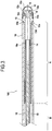
figure 3 représente le dispositif manuel de lafigure 1 vue selon le plan de coupe III, - la
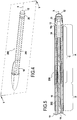
figure 4 représente un dispositif manuel selon un deuxième exemple correspondant à un mode de réalisation, vu en perspective, et - la
figure 5 représente le dispositif manuel de lafigure 4 vu selon le plan de coupe V. - Un premier exemple d'un dispositif manuel 100 est décrit en référence aux
figures 1 à 3 . - Le dispositif manuel 100 comprend un corps de préhension longitudinal 10, un coussinet pour écran capacitif 12, et une tige 14 s'étendant longitudinalement à l'intérieur du corps 10. Le dispositif manuel 100, et plus particulièrement le corps 10 et la tige 14 s'étendent selon la direction longitudinale X. Bien entendu, le corps 10 est creux de manière à recevoir la tige 14. Le corps 10 est isolant tandis que le coussinet 12 et la tige 14 sont conducteurs. Le coussinet 12 et la tige 14 sont en contact électrique.
- Le corps 10 présente deux extrémités 10a et 10b. L'extrémité 10a forme l'extrémité arrière, ou première extrémité, d'un stylo tandis que l'extrémité 10b forme l'extrémité avant, ou seconde extrémité, d'un stylo. Dans cet exemple, à l'exception de l'extrémité avant 10b qui présente une forme sensiblement tronconique, le corps 10 présente une forme sensiblement cylindrique de section hexagonale à l'extérieur et de section circulaire à l'intérieur.
- Le dispositif manuel 100 comprend une pointe d'écriture 16 montée sur l'extrémité 10b du corps 10 tandis que le coussinet 12 est monté sur l'extrémité 10a. Dans cet exemple, le dispositif manuel 100 forme ainsi un dispositif deux-en-un formant un stylo d'écriture et un stylet pour écran capacitif.
- Le coussinet 12 est monté sur le corps 10 par l'intermédiaire d'une embase 13. L'embase 13 est donc montée sur le corps 10 tandis que le coussinet 12 est monté sur l'embase 13. Dans cet exemple, le coussinet 12 est en contact électrique avec la tige 14 par l'intermédiaire de l'embase 13.
- Le coussinet 12 présente une extrémité distale 12a de coopération avec un écran capacitif, cette extrémité 12a présentant dans cet exemple une forme sensiblement hémisphérique creuse. L'extrémité 12a est disposée dans le prolongement d'une partie de fixation 12b de forme sensiblement cylindrique creuse. Cette partie de fixation 12b présente une collerette 12c disposée au voisinage de l'extrémité libre de la partie de fixation 12b, à l'intérieur de la partie de fixation 12b. Cette collerette 12c coopère par encliquetage avec une gorge annulaire 15 ménagée dans l'embase 13. Un anneau 20 est emmanché à force autour de la partie de fixation 12b et de l'embase 13 et serti sur l'embase 13 (cf.
Fig.3 ). Cet anneau 20 verrouille l'encliquetage du coussinet 12 sur l'embase 13. L'embase 13 présente un épaulement 13a recevant l'anneau 20 en appui. - L'embase 13 présent un trou traversant 13b selon la direction longitudinale X formant un évent pour équilibrer la pression interne du volume formée entre le coussinet 12 et l'embase 13 et la pression à l'extérieur dudit volume.
- L'embase 13 présente un épaulement 13c qui coopère avec le corps 10, par exemple par collage ou soudage (thermosoudage, soudure par ultrason, etc.). L'embase 13 et la tige 14 forment une seule et même pièce formée dans un seul et même matériau. Ainsi, dans cet exemple, la tige 14 est fixée sur le corps 10 par l'intermédiaire de l'embase 13. La zone de raccord entre l'embase 13 et la tige 14 présente une surépaisseur 13d de centrage qui coopère par complémentarité de forme avec une dépression 10c formée dans l'extrémité arrière 10a du corps 10. Par ailleurs, dans l'exemple où l'embase 13 est soudée au corps 10, la surépaisseur 13d contribue aussi à la fixation de l'embase 13 sur le corps 10. En effet, la surépaisseur 13d étant en contact privilégiée avec le corps, elle forme un cordon de soudure. Dans cet exemple, la surépaisseur 13d et le la dépression 10c sont de forme sensiblement annulaire.
- La tige 14 est creuse. L'évent 13c de l'embase 13 débouche dans la cavité interne de la tige creuse 14. La tige 14 s'étend à l'intérieur du corps 10 depuis l'extrémité arrière 10a. Comme représenté sur la
figure 3 , la tige 14 s'étend sur plus de 10% de la longueur du corps 10, une longueur étant de manière générale considérée selon la direction longitudinale X. Dans cet exemple, la tige s'étend sur environ 50% du corps 10, depuis l'extrémité arrière 10a. En d'autres termes, considérés selon la direction longitudinale X, la tige 12 s'étend sur environ la moitié du corps 10. - La pointe d'écriture 16, dans cet exemple une pointe à bille, est alimentée en encre par un réservoir 18 contenant une encre 19. Comme représenté sur la
figure 3 , le réservoir 18 s'étend en partie à l'intérieur de la tige 14. Plus particulièrement, l'extrémité arrière 18a du réservoir 18, c'est-à-dire l'extrémité du réservoir disposée à l'opposé de la pointe d'écriture 16, est disposée à l'intérieur de la tige 14. Plus généralement, le réservoir d'encre s'étend longitudinalement selon la direction longitudinale X en tout ou partie à l'intérieur de la tige 14. Dans cet exemple, une portion d'environ 50% depuis l'extrémité arrière 18a du réservoir 18 est disposée à l'intérieur de la tige. En d'autres termes, dans cet exemple, considéré selon la direction longitudinale X, environ la moitié arrière du réservoir 18 est disposé à l'intérieure de la tige 14. - Dans cet exemple, le diamètre extérieur de la tige est de 5.4 mm (millimètre) tandis que le diamètre intérieur du corps est 5.52 mm. De manière générale, on comprend que la tige 14 est espacée du corps 10. L'épaisseur du corps est comprise entre 1.2 mm et 1.5 mm. Ainsi, la distance radiale entre la surface (ou paroi) extérieure du corps et la surface (ou paroi) extérieure de la tige est comprise entre 1.26 mm et 1.56 mm. Plus généralement, les inventeurs ont constaté que le dispositif manuel 100 fonctionne de manière satisfaisante lorsque la distance radiale entre la surface extérieure du corps et la surface extérieure de la tige est inférieure à 5 mm.
- Dans cet exemple, le corps 10 est en PS, la tige 12 et l'embase 13 sont ABS comprenant une charge de 3% en masse de nanotubes de carbone. Le coussinet 14 est en matériau élastomère contenant des éléments conducteurs. Dans cet exemple, le coussinet 14 est en silicone chargé en particules de noir de carbone. L'anneau 20 est en cuivre chromé.
- Ainsi, grâce aux matériaux utilisés le coussinet 12 est en contact électrique indirect avec la tige 14 par l'intermédiaire de l'embase 13. L'anneau 20 étant en métal, il participe également au contact électrique entre l'embase 13 et le coussinet 12, mais sa fonction principale est le blocage mécanique du coussinet 12 sur l'embase 13.
- Lorsque l'utilisateur manipule le dispositif manuel 100 en le prenant par une zone du corps 10 en recouvrement selon la direction longitudinale X avec la tige 14, un écran capacitif est sensible au contact du coussinet 12. En d'autres termes, lorsque l'utilisateur manipule le dispositif manuel 100 et qu'il place sa main dans une zone longitudinale du corps 10 où s'étend la tige 14, un écran capacitif détecte la présence du coussinet 12 lorsque ce dernier est approché ou contacte l'écran capacitif. Sur la
figure 3 la zone A du corps 10 forme la zone de préhension du corps 10 en recouvrement longitudinal avec la tige 14 tandis que la zone B du corps 10 forme une zone de préhension qui n'est pas en recouvrement longitudinal avec la tige 14. - Un deuxième exemple d'un dispositif manuel 200 est maintenant décrit en référence aux
figures 4 et 5 . La seule différence avec le dispositif manuel 100 du premier exemple est la présence d'une couche en matériau conducteur sur la surface extérieure du corps. Ainsi, tous les éléments communs entre le premier et le deuxième exemple ne sont pas décrits à nouveau et conservent le même signe de référence. - Dans le deuxième exemple, le corps 10 présente sur sa surface extérieure une couche 202 en matériau conducteur. Dans cet exemple, la couche 202 comprend une feuille métallique collée par des moyens connus par ailleurs, par exemple par thermocollage, sur la surface extérieure du corps 10. La feuille métallique est en aluminium. Comme représenté sur la
figure 5 , la couche 202 ne s'étend pas jusqu'à l'extrémité arrière 10a du corps. Il n'y a donc pas de contact électrique entre la couche 202 et l'embase 13, l'anneau 20 ou le coussinet 12. En d'autres termes, la couche 202 est isolée de l'embase 13, de l'anneau 20 et du coussinet 12 (et bien entendu de la tige 14). - Cette couche 202 s'étend sur une zone C en recouvrement longitudinal sur environ toute la longueur de la tige 14. Par ailleurs la couche 202 s'étend sur une zone D qui n'est pas en recouvrement avec la tige. La zone D forment une zone de préhension supplémentaire par rapport à la zone de préhension A. Ainsi, grâce au revêtement 202, la zone de préhension efficace pour utiliser le coussinet 12 sur un écran capacitif est accrue, ce qui améliore l'ergonomie du dispositif manuel 200 vis-à-vis du dispositif manuel 100.
- Bien que la présente invention ait été décrite en se référant à des exemples de réalisation spécifiques, il est évident que des modifications et des changements peuvent être effectués sur ces exemples sans sortir de la portée générale de l'invention telle que définie par les revendications. En particulier, des caractéristiques individuelles des différents modes de réalisation illustrés/mentionnés peuvent être combinées dans des modes de réalisation additionnels. Par conséquent, la description et les dessins doivent être considérés dans un sens illustratif plutôt que restrictif.
Claims (13)
- Dispositif manuel comprenant un corps de préhension longitudinal (10) et un coussinet pour écran capacitif (12) monté sur une extrémité (10a) dudit corps (10), dans lequel le corps (10) est isolant tandis que le coussinet (12) est conducteur, dans lequel une tige (14) en matériau polymérique, chargé avec au moins un matériau conducteur et/ou comprenant un revêtement conducteur, est en contact électrique avec le coussinet (12) et s'étend longitudinalement à l'intérieur du corps (10), et dans lequel le corps (10) présente une surface extérieure, une couche en matériau conducteur (202) étant disposée sur la surface extérieure du corps (10), ladite couche (202) étant isolée du coussinet (12).
- Dispositif selon la revendication 1 dans lequel la tige (14) s'étend sur plus de 10% de la longueur du corps (10).
- Dispositif (100, 200) selon la revendication 1 ou 2, dans lequel le coussinet (12) est monté sur le corps (10) par l'intermédiaire d'une embase conductrice (13) tandis que la tige (14) est en contact électrique avec le coussinet (12) par l'intermédiaire de l'embase (13).
- Dispositif selon la revendication 3, dans lequel la tige (14) et l'embase (13) forment une seule et même pièce.
- Dispositif selon l'une quelconque des revendications 1 à 4, comprenant une pointe d'écriture ou équivalent (16).
- Dispositif selon la revendication 5, dans lequel la pointe d'écriture (16) est alimentée par un réservoir (18), ledit réservoir (18) étant disposé en tout ou partie à l'intérieur de la tige (14).
- Dispositif selon l'une quelconque des revendications 1 à 6, dans lequel le corps (10) est en matériau polymérique isolant, en bois, en céramique, en verre, ou équivalent.
- Dispositif selon l'une quelconque des revendications 1 à 7, dans lequel la couche (202) s'étend au moins en partie en recouvrement longitudinal avec la tige (14).
- Dispositif selon l'une quelconque des revendications 1 à 8, dans lequel la couche (202) s'étend sur au moins 30% de la longueur de la tige (14).
- Dispositif selon l'une quelconque des revendications 1 à 9, dans lequel la couche (202) comprend une feuille métallique ou un enduit conducteur.
- Dispositif selon l'une quelconque des revendications 1 à 10, dans lequel la tige (14) est espacée du corps (10).
- Dispositif selon l'une quelconque des revendications 1 à 11, dans lequel la tige et le corps sont sensiblement cylindriques, la tige et le corps présentant chacun une surface extérieure de forme sensiblement cylindrique, la distance radiale entre la surface extérieure de la tige et la surface extérieure du corps étant inférieure à 5 mm.
- Dispositif selon l'une quelconque des revendications 1 à 12, du type passif.
Applications Claiming Priority (2)
| Application Number | Priority Date | Filing Date | Title |
|---|---|---|---|
| FR1354146A FR3005288B1 (fr) | 2013-05-06 | 2013-05-06 | Dispositif manuel adapte pour un ecran capacitif |
| PCT/FR2014/050971 WO2014181053A1 (fr) | 2013-05-06 | 2014-04-22 | Dispositif manuel adapte pour un ecran capacitif |
Publications (2)
| Publication Number | Publication Date |
|---|---|
| EP2994322A1 EP2994322A1 (fr) | 2016-03-16 |
| EP2994322B1 true EP2994322B1 (fr) | 2017-08-09 |
Family
ID=49209482
Family Applications (1)
| Application Number | Title | Priority Date | Filing Date |
|---|---|---|---|
| EP14726693.6A Active EP2994322B1 (fr) | 2013-05-06 | 2014-04-22 | Dispositif manuel adapte pour un ecran capacitif |
Country Status (10)
| Country | Link |
|---|---|
| US (2) | US9857891B2 (fr) |
| EP (1) | EP2994322B1 (fr) |
| JP (1) | JP6388919B2 (fr) |
| KR (1) | KR20160021767A (fr) |
| CN (1) | CN105339182B (fr) |
| AR (1) | AR096169A1 (fr) |
| BR (1) | BR112015027916B1 (fr) |
| FR (1) | FR3005288B1 (fr) |
| MX (1) | MX365299B (fr) |
| WO (1) | WO2014181053A1 (fr) |
Families Citing this family (7)
| Publication number | Priority date | Publication date | Assignee | Title |
|---|---|---|---|---|
| FR3005288B1 (fr) | 2013-05-06 | 2015-05-15 | Bic Soc | Dispositif manuel adapte pour un ecran capacitif |
| FR3006461B1 (fr) * | 2013-05-29 | 2015-06-05 | Bic Soc | Dispositif manuel comprenant un embout inversable pour ecran capacitif |
| FR3014217B1 (fr) * | 2013-12-02 | 2017-02-24 | SOCIéTé BIC | Dispositif manuel comprenant un embout amovible pour ecran capacitif |
| FR3028629B1 (fr) | 2014-11-19 | 2017-01-27 | SOCIéTé BIC | Dispositif manuel comprenant un embout inversable pour ecran capacitif |
| FR3042887B1 (fr) | 2015-10-27 | 2017-11-17 | SOCIéTé BIC | Instrument d'ecriture a pointe retractable comprenant un coussinet pour ecran capacitif |
| US10754447B2 (en) * | 2018-01-10 | 2020-08-25 | Microsoft Technology Licensing, Llc | Stylus capsule |
| US10775902B2 (en) * | 2018-09-19 | 2020-09-15 | Apple Inc. | Stylus with glass component |
Family Cites Families (136)
| Publication number | Priority date | Publication date | Assignee | Title |
|---|---|---|---|---|
| US4289927A (en) | 1979-11-13 | 1981-09-15 | Kurta Corporation | Graphic communication apparatus |
| FR2483100B1 (fr) | 1980-05-23 | 1985-12-13 | Option Sa | Style scripteur pour tablette graphique, servant en meme temps de capteur capacitif |
| US5488204A (en) | 1992-06-08 | 1996-01-30 | Synaptics, Incorporated | Paintbrush stylus for capacitive touch sensor pad |
| US5828011A (en) | 1994-02-04 | 1998-10-27 | At&T Global Information Solutions Company | High voltage stylus for portable computer |
| JPH08137602A (ja) | 1994-11-09 | 1996-05-31 | Alps Electric Co Ltd | スタイラスペン |
| KR100399564B1 (ko) | 1994-12-08 | 2003-12-06 | 주식회사 하이닉스반도체 | 전기전도성및유연성이있는팁을구비한정전기펜장치및방법 |
| JP2767098B2 (ja) | 1995-06-06 | 1998-06-18 | 株式会社ワコム | 位置指示ユニット及びスタイラスペン |
| US5914708A (en) | 1996-04-04 | 1999-06-22 | Cirque Corporation | Computer input stylus method and apparatus |
| JP2877089B2 (ja) | 1996-07-17 | 1999-03-31 | 日本電気株式会社 | ペ ン |
| US6707451B1 (en) | 1996-09-11 | 2004-03-16 | Pilot Precision Kabushiki Kaisha | Input pen |
| JP3426890B2 (ja) | 1996-12-25 | 2003-07-14 | アルプス電気株式会社 | 入力ペン |
| US5913629A (en) | 1998-05-07 | 1999-06-22 | Ttools, Llc | Writing implement including an input stylus |
| CN1483187A (zh) | 2000-11-22 | 2004-03-17 | 利用永久磁铁的指示笔输入器 | |
| US6801192B2 (en) | 2000-12-13 | 2004-10-05 | Wacom Company Ltd. | Pen-shaped coordinate pointing device |
| JP2002236540A (ja) | 2001-02-09 | 2002-08-23 | Kunio Obata | 電子機器の入力押下ペン |
| US20020021291A1 (en) | 2001-03-26 | 2002-02-21 | Cook Brandt A. | Stylus with light emitting diode |
| US20030034962A1 (en) | 2001-08-14 | 2003-02-20 | Chao-Chi Huang | Touch control pen for PDA |
| EP1291200B1 (fr) | 2001-09-08 | 2005-12-28 | Top-Q Ag | Instrument d'écriture avec un élément-crayon tactile intégré et une source de lumière UV |
| US6937231B2 (en) | 2001-09-21 | 2005-08-30 | Wacom Co., Ltd. | Pen-shaped coordinate pointing device |
| US6882340B2 (en) | 2001-10-19 | 2005-04-19 | Wacom Co., Ltd. | Electronic pen |
| US20030095115A1 (en) | 2001-11-22 | 2003-05-22 | Taylor Brian | Stylus input device utilizing a permanent magnet |
| US20030128193A1 (en) | 2002-01-04 | 2003-07-10 | Quarton Inc. | Touch control pen for PDA |
| US20030132923A1 (en) | 2002-01-15 | 2003-07-17 | Pro Eton Corporation | Combination touch-sensitive screen stylus |
| JP2004005415A (ja) | 2002-04-19 | 2004-01-08 | Sharp Corp | 入力装置および入出力一体型表示装置 |
| KR100685954B1 (ko) | 2002-12-24 | 2007-02-23 | 엘지.필립스 엘시디 주식회사 | 터치 패널 |
| US7077594B1 (en) | 2003-02-25 | 2006-07-18 | Palm, Incorporated | Expandable and contractible stylus |
| JP2004310482A (ja) | 2003-04-08 | 2004-11-04 | Quasar System Inc | 入力要素およびタッチパッド入力方式 |
| US7068262B2 (en) | 2003-06-09 | 2006-06-27 | Leapfrog Enterprises, Inc. | Writing stylus for electrographic position location apparatus |
| DE20312529U1 (de) * | 2003-08-12 | 2004-02-12 | Herlitz Pbs Ag | Schreibgerät mit gefederter PDA Spitze |
| US6985138B2 (en) | 2003-08-29 | 2006-01-10 | Motorola, Inc. | Input writing device |
| CA2538107A1 (fr) | 2003-09-12 | 2005-03-31 | Cirque Corporation | Stylet attache s'utilisant avec un pave tactile sensible a la capacitance |
| US6921223B2 (en) | 2003-09-15 | 2005-07-26 | Sanford, L.P. | Combo pen |
| US20050078096A1 (en) | 2003-10-08 | 2005-04-14 | Kuang-Cheng Fan | Touch pen module |
| US20050248549A1 (en) | 2004-05-06 | 2005-11-10 | Dietz Paul H | Hand-held haptic stylus |
| JP2006065757A (ja) | 2004-08-30 | 2006-03-09 | Wacom Co Ltd | 座標指示器 |
| US20060239761A1 (en) | 2005-04-21 | 2006-10-26 | Carl Cetera | Pen |
| FR2886883B1 (fr) | 2005-06-13 | 2007-09-14 | Ya Chiao Liu | Stylo d'ecriture telescopique |
| US7612767B1 (en) | 2005-08-24 | 2009-11-03 | Griffin Technology, Inc. | Trackpad pen for use with computer touchpad |
| US9201556B2 (en) | 2006-11-08 | 2015-12-01 | 3M Innovative Properties Company | Touch location sensing system and method employing sensor data fitting to a predefined curve |
| US20080149401A1 (en) | 2006-12-20 | 2008-06-26 | 3M Innovative Properties Company | Untethered stylus employing separate communication channels |
| US20080266267A1 (en) | 2007-04-30 | 2008-10-30 | Chih-Chang Chang | Pen for touch pad of a laptop |
| DE602007010250D1 (de) | 2007-05-24 | 2010-12-16 | Giga Byte Comm Inc | Touch-Pen mit Antenne und elektronische Vorrichtung mit dem Touch-Pen |
| TWI361995B (en) | 2007-07-03 | 2012-04-11 | Elan Microelectronics Corp | Input device of capacitive touchpad |
| CN101373410B (zh) | 2007-08-20 | 2011-03-23 | 深圳富泰宏精密工业有限公司 | 手写笔及带有该手写笔的便携式电子装置 |
| KR100890366B1 (ko) | 2007-09-05 | 2009-03-25 | (주)펜앤프리 | 입력펜 및 이를 이용하는 입력 시스템 |
| JP5011541B2 (ja) | 2007-09-11 | 2012-08-29 | 株式会社ワコム | 位置指示器 |
| JP5109171B2 (ja) | 2007-09-18 | 2012-12-26 | 株式会社ワコム | 位置指示器、位置入力装置及びコンピュータシステム |
| US20090122029A1 (en) | 2007-11-13 | 2009-05-14 | Newvit Co. Ltd. | Stylus pen |
| TW200925942A (en) | 2007-12-10 | 2009-06-16 | Mitac Int Corp | Stylus device with multi-color switching |
| US8355008B2 (en) | 2007-12-14 | 2013-01-15 | Songtak Technology Co., Ltd. | Touch component for protecting capacitive panel |
| US20100214252A1 (en) | 2007-12-14 | 2010-08-26 | Mao-Sung Wu | Touch panel component for capacitive panel |
| TW200928887A (en) | 2007-12-28 | 2009-07-01 | Htc Corp | Stylus and electronic device |
| JP5094376B2 (ja) | 2007-12-28 | 2012-12-12 | 株式会社ワコム | 位置検出装置 |
| TW200937260A (en) | 2008-02-25 | 2009-09-01 | J Touch Corp | Capacitive stylus pen |
| JP5235472B2 (ja) | 2008-04-01 | 2013-07-10 | 株式会社ワコム | 電子ペン |
| US20090256824A1 (en) | 2008-04-11 | 2009-10-15 | Sony Ericsson Mobile Communications Ab | Pointer device for capacitive sensitive touch screens |
| US20090266626A1 (en) | 2008-04-25 | 2009-10-29 | Karl Robb | Flexible Stylus Tip With Flat Contact Surface |
| US8212795B2 (en) | 2008-05-21 | 2012-07-03 | Hypercom Corporation | Payment terminal stylus with touch screen contact detection |
| TWI370988B (en) | 2008-05-28 | 2012-08-21 | Delta Electronics Inc | Touch screen apparatus |
| US20100006350A1 (en) | 2008-07-11 | 2010-01-14 | Elias John G | Stylus Adapted For Low Resolution Touch Sensor Panels |
| DE202008011276U1 (de) | 2008-08-25 | 2008-12-11 | Window Touch Technology Co., Ltd., Banciao City | Stift für berührungsempfindliche Anzeigevorrichtungen |
| US8536471B2 (en) | 2008-08-25 | 2013-09-17 | N-Trig Ltd. | Pressure sensitive stylus for a digitizer |
| TW201011600A (en) | 2008-09-01 | 2010-03-16 | Turbotouch Technology Inc E | Electromagnetic stylus for operating a capacitive touch panel |
| US20100053120A1 (en) | 2008-09-03 | 2010-03-04 | Chang An-Yu | Touchscreen stylus |
| JP2010067117A (ja) | 2008-09-12 | 2010-03-25 | Mitsubishi Electric Corp | タッチパネル装置 |
| US8482545B2 (en) | 2008-10-02 | 2013-07-09 | Wacom Co., Ltd. | Combination touch and transducer input system and method |
| TWM350750U (en) | 2008-10-03 | 2009-02-11 | Inventec Appliances Corp | Electric pen |
| CN101751157B (zh) | 2008-12-12 | 2013-06-26 | 汉王科技股份有限公司 | 便携手写笔 |
| KR20100082410A (ko) | 2009-01-09 | 2010-07-19 | (주)쉘라인 | 스타일러스 펜 |
| KR20100082409A (ko) | 2009-01-09 | 2010-07-19 | (주)쉘라인 | 스타일러스 펜 |
| JP5358834B2 (ja) | 2009-02-17 | 2013-12-04 | 株式会社ワコム | 位置指示器及び入力装置 |
| JP5286609B2 (ja) | 2009-02-24 | 2013-09-11 | 株式会社ワコム | 位置指示器 |
| CN101840274A (zh) | 2009-03-17 | 2010-09-22 | 汉王科技股份有限公司 | 便携式手写笔 |
| CN201440247U (zh) * | 2009-06-05 | 2010-04-21 | 健博贸易有限公司 | 手写笔 |
| US9417738B2 (en) | 2009-06-12 | 2016-08-16 | Synaptics Incorporated | Untethered active pen and a method for communicating with a capacitive sensing device using the untethered active pen |
| WO2011008533A2 (fr) * | 2009-06-29 | 2011-01-20 | Gerald Leto | Appareil multifonctionnel d'écriture avec stylet pour écran tactile capacitif |
| JP2011018090A (ja) | 2009-07-07 | 2011-01-27 | Panasonic Corp | 電子ペン及び電子ペンシステム |
| CN102023723A (zh) * | 2009-09-09 | 2011-04-20 | 和硕联合科技股份有限公司 | 触控笔 |
| JP5295914B2 (ja) | 2009-09-18 | 2013-09-18 | 株式会社ジャパンディスプレイ | 表示装置 |
| CN102033624A (zh) | 2009-09-29 | 2011-04-27 | 深圳富泰宏精密工业有限公司 | 电子装置手写笔 |
| CN102053730A (zh) | 2009-10-28 | 2011-05-11 | 深圳富泰宏精密工业有限公司 | 触控笔 |
| JP5345050B2 (ja) | 2009-12-25 | 2013-11-20 | 株式会社ワコム | 指示体、位置検出装置及び位置検出方法 |
| US8917262B2 (en) | 2010-01-08 | 2014-12-23 | Integrated Digital Technologies, Inc. | Stylus and touch input system |
| TWM385746U (en) * | 2010-01-15 | 2010-08-01 | Waltop Int Corp | Electromagnetic pointer |
| KR100962977B1 (ko) | 2010-01-29 | 2010-06-10 | 전동연 | 정전식 스타일러스 |
| KR101047589B1 (ko) | 2010-04-09 | 2011-07-07 | (주)삼원에스티 | 정전용량 방식의 터치 인식이 가능한 필기구 |
| KR100992558B1 (ko) | 2010-04-22 | 2010-11-08 | 엑스지 솔루션스 엘엘씨 | 휴대 단말기용 스타일러스 펜 |
| US20110304577A1 (en) | 2010-06-11 | 2011-12-15 | Sp Controls, Inc. | Capacitive touch screen stylus |
| TWM393735U (en) | 2010-06-29 | 2010-12-01 | Te-Hsiang Fang | Touch screen pen for capacitive type touch screen |
| KR101680253B1 (ko) | 2010-07-27 | 2016-11-29 | 삼성디스플레이 주식회사 | 정전용량 터치패널용 스타일러스펜 |
| US20120044214A1 (en) | 2010-08-23 | 2012-02-23 | Belkin International, Inc. | Electronic device accessory and method of providing the same |
| KR101787750B1 (ko) * | 2010-12-01 | 2017-10-19 | 삼성전자주식회사 | 정전식 스타일러스 펜 |
| JP2012123744A (ja) | 2010-12-10 | 2012-06-28 | Shin Etsu Polymer Co Ltd | 静電容量式入力装置およびその製造方法、静電容量式入力装置の入力方法 |
| JP4683505B1 (ja) | 2010-12-14 | 2011-05-18 | 株式会社ワコム | 位置指示器 |
| JP3169005U (ja) * | 2010-12-14 | 2011-07-07 | 君達創新科技股▲ふん▼有限公司 | タッチペン |
| KR101056757B1 (ko) | 2010-12-21 | 2011-08-12 | (주)대영케이티엑스 | 정전식 터치펜의 감응부 및 이의 제조방법 |
| CN102053740B (zh) | 2010-12-27 | 2013-02-13 | 清华大学 | 触控笔 |
| CN102096484B (zh) | 2010-12-27 | 2013-04-10 | 清华大学 | 触控笔 |
| CN102053737B (zh) | 2010-12-27 | 2013-01-09 | 清华大学 | 触控笔 |
| US20120327045A1 (en) | 2011-01-03 | 2012-12-27 | Peter James Skinner | Devices and processes for manual data input |
| WO2012103241A1 (fr) | 2011-01-28 | 2012-08-02 | Yair Greenberg | Article produisant une réponse de contact et de déplacement guidés et procédé |
| JP5663329B2 (ja) * | 2011-01-28 | 2015-02-04 | 三菱鉛筆株式会社 | 静電容量型タッチペンを搭載した筆記具 |
| WO2012103323A1 (fr) | 2011-01-28 | 2012-08-02 | More/Real Llc | Stylet |
| JP2014102531A (ja) * | 2011-03-16 | 2014-06-05 | Panasonic Corp | 静電容量方式タッチパネル用タッチペン |
| US8847930B2 (en) | 2011-04-17 | 2014-09-30 | Wimo Labs LLC | Electrically conductive touch pen |
| JP4840891B1 (ja) * | 2011-04-19 | 2011-12-21 | 株式会社ワコム | コードレス型の位置指示器 |
| DE202011104019U1 (de) | 2011-08-03 | 2011-11-08 | Chia-Yu Chang | Griffel für die Anwendung auf unterschiedlichen Tastfeldern |
| JP2013077105A (ja) * | 2011-09-30 | 2013-04-25 | Fujitsu Ltd | タッチペン |
| JPWO2013057862A1 (ja) | 2011-10-20 | 2015-04-02 | シャープ株式会社 | 情報入力ペン |
| US20130106771A1 (en) * | 2011-10-28 | 2013-05-02 | Atmel Corporation | Active-Stylus Nib with Rolling-Ball Tip |
| JP3173117U (ja) * | 2011-11-07 | 2012-01-26 | 圓凱科技實業股▲分▼有限公司 | 交換式タッチペン |
| WO2013082761A1 (fr) | 2011-12-06 | 2013-06-13 | Chuang Hsin-Hung | Accessoire de commande tactile portable |
| JP2013125415A (ja) | 2011-12-14 | 2013-06-24 | Pilot Corporation | 入力ペン |
| WO2013091182A1 (fr) | 2011-12-21 | 2013-06-27 | Chuang Hsin-Hung | Accessoire capacitif manuel de commande tactile |
| TWM439852U (en) * | 2012-01-20 | 2012-10-21 | Kooner Technology Hk Co Ltd | Insulated stylus |
| JP5890706B2 (ja) | 2012-02-29 | 2016-03-22 | ミクロ株式会社 | タッチペン |
| US20130249870A1 (en) | 2012-03-22 | 2013-09-26 | Motorola Mobility, Inc. | Dual mode active stylus for writing both on a capacitive touchscreen and paper |
| JP2013206053A (ja) | 2012-03-28 | 2013-10-07 | Pilot Corporation | 静電型入力ペン |
| US20130278537A1 (en) | 2012-04-19 | 2013-10-24 | Motorola Mobility, Inc. | Touchscreen writing system |
| DE102012010965A1 (de) | 2012-05-29 | 2013-12-05 | J. S. Staedtler Gmbh & Co. Kg | Eingabegerät für berührungsempfindliche, kapazitive Displays |
| DE102012010966B4 (de) | 2012-05-29 | 2026-05-13 | Staedtler Se | Verwendung eines Gerätes als Eingabegerät für berührungsempfindliche, kapazitive Displays |
| DE202012005460U1 (de) | 2012-05-29 | 2013-09-02 | J. S. Staedtler Gmbh & Co. Kg | Eingabegerät für berührungsempfindliche, kapazitive Displays |
| JP3177874U (ja) | 2012-06-01 | 2012-08-23 | 岩崎金属工業株式会社 | 電子機器用タッチペン |
| US9129180B2 (en) * | 2012-08-17 | 2015-09-08 | Blackberry Limited | Combination pen refill cartridge and active stylus |
| KR101967727B1 (ko) | 2012-08-28 | 2019-04-10 | 삼성전자 주식회사 | 터치펜 및 이를 구비하는 휴대단말장치 |
| WO2014032282A1 (fr) | 2012-08-31 | 2014-03-06 | Chuang Hsin-Hung | Accessoire ornemental à commande tactile |
| JP6009900B2 (ja) | 2012-10-16 | 2016-10-19 | シャープ株式会社 | ペン型入力装置及びそれを備えた携帯端末 |
| JP5266415B1 (ja) | 2012-11-08 | 2013-08-21 | 日本蚕毛染色株式会社 | 静電容量式タッチパネル用筆記具 |
| FR3005288B1 (fr) | 2013-05-06 | 2015-05-15 | Bic Soc | Dispositif manuel adapte pour un ecran capacitif |
| FR3005287B1 (fr) | 2013-05-06 | 2017-04-14 | SOCIéTé BIC | Embout pour ecran capacitif |
| DE102013008231A1 (de) | 2013-05-08 | 2014-11-13 | J. S. Staedtler Gmbh & Co. Kg | Verwendung eines Gerätes als Eingabegerät für berührungsempfindliche, kapazitive Oberflächen |
| DE102013008232A1 (de) | 2013-05-08 | 2014-11-13 | J. S. Staedtler Gmbh & Co. Kg | Eingabegerät für berührungsempfindliche, kapazitive Oberflächen |
| WO2015013533A2 (fr) | 2013-07-24 | 2015-01-29 | FiftyThree, Inc. | Procédés et appareil pour la mise en œuvre d'une double fonctionnalité de pointe dans un stylet |
| WO2015019883A1 (fr) | 2013-08-03 | 2015-02-12 | 株式会社ワコム | Indicateur de position |
| TW201516766A (zh) | 2013-10-18 | 2015-05-01 | Waltop Int Corp | 觸控筆 |
| FR3012632A1 (fr) | 2013-10-29 | 2015-05-01 | Abdelaali Zitouni | Stylet adaptable a differents instruments d'ecriture |
-
2013
- 2013-05-06 FR FR1354146A patent/FR3005288B1/fr active Active
-
2014
- 2014-04-22 EP EP14726693.6A patent/EP2994322B1/fr active Active
- 2014-04-22 WO PCT/FR2014/050971 patent/WO2014181053A1/fr not_active Ceased
- 2014-04-22 BR BR112015027916-3A patent/BR112015027916B1/pt active IP Right Grant
- 2014-04-22 JP JP2016512403A patent/JP6388919B2/ja not_active Expired - Fee Related
- 2014-04-22 MX MX2015015477A patent/MX365299B/es active IP Right Grant
- 2014-04-22 US US14/889,011 patent/US9857891B2/en active Active
- 2014-04-22 KR KR1020157034770A patent/KR20160021767A/ko not_active Ceased
- 2014-04-22 CN CN201480025732.4A patent/CN105339182B/zh active Active
- 2014-05-05 AR ARP140101815A patent/AR096169A1/es active IP Right Grant
-
2016
- 2016-02-23 US US15/050,910 patent/US9535515B2/en active Active
Also Published As
| Publication number | Publication date |
|---|---|
| FR3005288A1 (fr) | 2014-11-07 |
| CN105339182A (zh) | 2016-02-17 |
| MX365299B (es) | 2019-05-29 |
| CN105339182B (zh) | 2018-10-09 |
| US9535515B2 (en) | 2017-01-03 |
| BR112015027916B1 (pt) | 2021-01-19 |
| EP2994322A1 (fr) | 2016-03-16 |
| US20160216786A1 (en) | 2016-07-28 |
| US9857891B2 (en) | 2018-01-02 |
| MX2015015477A (es) | 2016-10-21 |
| KR20160021767A (ko) | 2016-02-26 |
| WO2014181053A1 (fr) | 2014-11-13 |
| JP6388919B2 (ja) | 2018-09-12 |
| AR096169A1 (es) | 2015-12-09 |
| FR3005288B1 (fr) | 2015-05-15 |
| US20160077612A1 (en) | 2016-03-17 |
| JP2016524743A (ja) | 2016-08-18 |
Similar Documents
| Publication | Publication Date | Title |
|---|---|---|
| EP2994322A1 (fr) | Dispositif manuel adapte pour un ecran capacitif | |
| FR3015627A1 (fr) | Ensemble comprenant deux elements de tuyauterie montes avec un joint d'interface | |
| EP3368968B1 (fr) | Instrument d'écriture à pointe rétractable comprenant un coussinet pour écran capacitif | |
| EP2994321B1 (fr) | Embout pour écran capacitif | |
| FR2676026A1 (fr) | Element d'alimentation en carburant pour un vehicule. | |
| EP3005051B1 (fr) | Dispositif manuel comprenant un embout inversable pour écran capacitif | |
| WO2016079422A1 (fr) | Dispositif manuel comprenant un embout inversable pour ecran capacitif | |
| EP3256261B1 (fr) | Agencement de montage pour un distributeur | |
| FR3071192B1 (fr) | Instrument d'ecriture comprenant deux pointes d'ecriture concentriques | |
| EP3077894B1 (fr) | Dispositif manuel comprenant un embout amovible pour ecran capacitif | |
| EP3080687A2 (fr) | Dispositif manuel et ensemble multifonctionnel | |
| EP3263982B1 (fr) | Procede pour realiser une marque electroluminescente sur une paroi exterieure d'un aeronef, bande de marquage comprenant ladite marque electroluminescente et aeronef comprenant ladite marque electroluminescente | |
| WO2009095599A1 (fr) | Agencement pour l'evacuation d'eau sur une surface optique de vehicule automobile | |
| WO2006030095A1 (fr) | Instrument d’ecriture | |
| FR3088048A1 (fr) | Support de capteur pour piece de carrosserie | |
| FR3056280A1 (fr) | Embout pour gaine tubulaire de matiere plastique souple | |
| FR3075454B1 (fr) | Element du type capteur surmoule et son procede de fabrication, et son procede de montage pour sa connexion electrique | |
| FR2973931A1 (fr) | Dispositif de commande equipe d'une molette tournante | |
| WO2024008641A1 (fr) | Ensemble et procédé de fabrication correspondant | |
| FR2462280A1 (fr) | Pneumatique increvable pour bicyclette ou analogue et son procede de fabrication | |
| FR3089152A1 (fr) | Chambre de pneu torique | |
| FR3026841A1 (fr) | Capteur capacitif |
Legal Events
| Date | Code | Title | Description |
|---|---|---|---|
| PUAI | Public reference made under article 153(3) epc to a published international application that has entered the european phase |
Free format text: ORIGINAL CODE: 0009012 |
|
| 17P | Request for examination filed |
Effective date: 20151204 |
|
| AK | Designated contracting states |
Kind code of ref document: A1 Designated state(s): AL AT BE BG CH CY CZ DE DK EE ES FI FR GB GR HR HU IE IS IT LI LT LU LV MC MK MT NL NO PL PT RO RS SE SI SK SM TR |
|
| AX | Request for extension of the european patent |
Extension state: BA ME |
|
| DAX | Request for extension of the european patent (deleted) | ||
| GRAP | Despatch of communication of intention to grant a patent |
Free format text: ORIGINAL CODE: EPIDOSNIGR1 |
|
| INTG | Intention to grant announced |
Effective date: 20161201 |
|
| RIN1 | Information on inventor provided before grant (corrected) |
Inventor name: ROLION, FRANCK |
|
| GRAS | Grant fee paid |
Free format text: ORIGINAL CODE: EPIDOSNIGR3 |
|
| GRAA | (expected) grant |
Free format text: ORIGINAL CODE: 0009210 |
|
| AK | Designated contracting states |
Kind code of ref document: B1 Designated state(s): AL AT BE BG CH CY CZ DE DK EE ES FI FR GB GR HR HU IE IS IT LI LT LU LV MC MK MT NL NO PL PT RO RS SE SI SK SM TR |
|
| REG | Reference to a national code |
Ref country code: GB Ref legal event code: FG4D Free format text: NOT ENGLISH |
|
| REG | Reference to a national code |
Ref country code: CH Ref legal event code: EP Ref country code: AT Ref legal event code: REF Ref document number: 916381 Country of ref document: AT Kind code of ref document: T Effective date: 20170815 |
|
| REG | Reference to a national code |
Ref country code: IE Ref legal event code: FG4D Free format text: LANGUAGE OF EP DOCUMENT: FRENCH |
|
| REG | Reference to a national code |
Ref country code: DE Ref legal event code: R096 Ref document number: 602014012851 Country of ref document: DE |
|
| REG | Reference to a national code |
Ref country code: NL Ref legal event code: MP Effective date: 20170809 |
|
| REG | Reference to a national code |
Ref country code: LT Ref legal event code: MG4D |
|
| REG | Reference to a national code |
Ref country code: AT Ref legal event code: MK05 Ref document number: 916381 Country of ref document: AT Kind code of ref document: T Effective date: 20170809 |
|
| PG25 | Lapsed in a contracting state [announced via postgrant information from national office to epo] |
Ref country code: HR Free format text: LAPSE BECAUSE OF FAILURE TO SUBMIT A TRANSLATION OF THE DESCRIPTION OR TO PAY THE FEE WITHIN THE PRESCRIBED TIME-LIMIT Effective date: 20170809 Ref country code: FI Free format text: LAPSE BECAUSE OF FAILURE TO SUBMIT A TRANSLATION OF THE DESCRIPTION OR TO PAY THE FEE WITHIN THE PRESCRIBED TIME-LIMIT Effective date: 20170809 Ref country code: NL Free format text: LAPSE BECAUSE OF FAILURE TO SUBMIT A TRANSLATION OF THE DESCRIPTION OR TO PAY THE FEE WITHIN THE PRESCRIBED TIME-LIMIT Effective date: 20170809 Ref country code: SE Free format text: LAPSE BECAUSE OF FAILURE TO SUBMIT A TRANSLATION OF THE DESCRIPTION OR TO PAY THE FEE WITHIN THE PRESCRIBED TIME-LIMIT Effective date: 20170809 Ref country code: NO Free format text: LAPSE BECAUSE OF FAILURE TO SUBMIT A TRANSLATION OF THE DESCRIPTION OR TO PAY THE FEE WITHIN THE PRESCRIBED TIME-LIMIT Effective date: 20171109 Ref country code: LT Free format text: LAPSE BECAUSE OF FAILURE TO SUBMIT A TRANSLATION OF THE DESCRIPTION OR TO PAY THE FEE WITHIN THE PRESCRIBED TIME-LIMIT Effective date: 20170809 Ref country code: AT Free format text: LAPSE BECAUSE OF FAILURE TO SUBMIT A TRANSLATION OF THE DESCRIPTION OR TO PAY THE FEE WITHIN THE PRESCRIBED TIME-LIMIT Effective date: 20170809 |
|
| PG25 | Lapsed in a contracting state [announced via postgrant information from national office to epo] |
Ref country code: GR Free format text: LAPSE BECAUSE OF FAILURE TO SUBMIT A TRANSLATION OF THE DESCRIPTION OR TO PAY THE FEE WITHIN THE PRESCRIBED TIME-LIMIT Effective date: 20171110 Ref country code: ES Free format text: LAPSE BECAUSE OF FAILURE TO SUBMIT A TRANSLATION OF THE DESCRIPTION OR TO PAY THE FEE WITHIN THE PRESCRIBED TIME-LIMIT Effective date: 20170809 Ref country code: PL Free format text: LAPSE BECAUSE OF FAILURE TO SUBMIT A TRANSLATION OF THE DESCRIPTION OR TO PAY THE FEE WITHIN THE PRESCRIBED TIME-LIMIT Effective date: 20170809 Ref country code: IS Free format text: LAPSE BECAUSE OF FAILURE TO SUBMIT A TRANSLATION OF THE DESCRIPTION OR TO PAY THE FEE WITHIN THE PRESCRIBED TIME-LIMIT Effective date: 20171209 Ref country code: BG Free format text: LAPSE BECAUSE OF FAILURE TO SUBMIT A TRANSLATION OF THE DESCRIPTION OR TO PAY THE FEE WITHIN THE PRESCRIBED TIME-LIMIT Effective date: 20171109 Ref country code: RS Free format text: LAPSE BECAUSE OF FAILURE TO SUBMIT A TRANSLATION OF THE DESCRIPTION OR TO PAY THE FEE WITHIN THE PRESCRIBED TIME-LIMIT Effective date: 20170809 Ref country code: LV Free format text: LAPSE BECAUSE OF FAILURE TO SUBMIT A TRANSLATION OF THE DESCRIPTION OR TO PAY THE FEE WITHIN THE PRESCRIBED TIME-LIMIT Effective date: 20170809 |
|
| REG | Reference to a national code |
Ref country code: FR Ref legal event code: PLFP Year of fee payment: 5 |
|
| PG25 | Lapsed in a contracting state [announced via postgrant information from national office to epo] |
Ref country code: RO Free format text: LAPSE BECAUSE OF FAILURE TO SUBMIT A TRANSLATION OF THE DESCRIPTION OR TO PAY THE FEE WITHIN THE PRESCRIBED TIME-LIMIT Effective date: 20170809 Ref country code: DK Free format text: LAPSE BECAUSE OF FAILURE TO SUBMIT A TRANSLATION OF THE DESCRIPTION OR TO PAY THE FEE WITHIN THE PRESCRIBED TIME-LIMIT Effective date: 20170809 Ref country code: CZ Free format text: LAPSE BECAUSE OF FAILURE TO SUBMIT A TRANSLATION OF THE DESCRIPTION OR TO PAY THE FEE WITHIN THE PRESCRIBED TIME-LIMIT Effective date: 20170809 |
|
| REG | Reference to a national code |
Ref country code: DE Ref legal event code: R097 Ref document number: 602014012851 Country of ref document: DE |
|
| PG25 | Lapsed in a contracting state [announced via postgrant information from national office to epo] |
Ref country code: SK Free format text: LAPSE BECAUSE OF FAILURE TO SUBMIT A TRANSLATION OF THE DESCRIPTION OR TO PAY THE FEE WITHIN THE PRESCRIBED TIME-LIMIT Effective date: 20170809 Ref country code: SM Free format text: LAPSE BECAUSE OF FAILURE TO SUBMIT A TRANSLATION OF THE DESCRIPTION OR TO PAY THE FEE WITHIN THE PRESCRIBED TIME-LIMIT Effective date: 20170809 Ref country code: EE Free format text: LAPSE BECAUSE OF FAILURE TO SUBMIT A TRANSLATION OF THE DESCRIPTION OR TO PAY THE FEE WITHIN THE PRESCRIBED TIME-LIMIT Effective date: 20170809 |
|
| PLBE | No opposition filed within time limit |
Free format text: ORIGINAL CODE: 0009261 |
|
| STAA | Information on the status of an ep patent application or granted ep patent |
Free format text: STATUS: NO OPPOSITION FILED WITHIN TIME LIMIT |
|
| 26N | No opposition filed |
Effective date: 20180511 |
|
| PG25 | Lapsed in a contracting state [announced via postgrant information from national office to epo] |
Ref country code: SI Free format text: LAPSE BECAUSE OF FAILURE TO SUBMIT A TRANSLATION OF THE DESCRIPTION OR TO PAY THE FEE WITHIN THE PRESCRIBED TIME-LIMIT Effective date: 20170809 |
|
| PG25 | Lapsed in a contracting state [announced via postgrant information from national office to epo] |
Ref country code: MT Free format text: LAPSE BECAUSE OF FAILURE TO SUBMIT A TRANSLATION OF THE DESCRIPTION OR TO PAY THE FEE WITHIN THE PRESCRIBED TIME-LIMIT Effective date: 20170809 |
|
| PG25 | Lapsed in a contracting state [announced via postgrant information from national office to epo] |
Ref country code: MC Free format text: LAPSE BECAUSE OF FAILURE TO SUBMIT A TRANSLATION OF THE DESCRIPTION OR TO PAY THE FEE WITHIN THE PRESCRIBED TIME-LIMIT Effective date: 20170809 |
|
| REG | Reference to a national code |
Ref country code: CH Ref legal event code: PL |
|
| REG | Reference to a national code |
Ref country code: BE Ref legal event code: MM Effective date: 20180430 |
|
| REG | Reference to a national code |
Ref country code: IE Ref legal event code: MM4A |
|
| PG25 | Lapsed in a contracting state [announced via postgrant information from national office to epo] |
Ref country code: LU Free format text: LAPSE BECAUSE OF NON-PAYMENT OF DUE FEES Effective date: 20180422 |
|
| PG25 | Lapsed in a contracting state [announced via postgrant information from national office to epo] |
Ref country code: CH Free format text: LAPSE BECAUSE OF NON-PAYMENT OF DUE FEES Effective date: 20180430 Ref country code: BE Free format text: LAPSE BECAUSE OF NON-PAYMENT OF DUE FEES Effective date: 20180430 Ref country code: LI Free format text: LAPSE BECAUSE OF NON-PAYMENT OF DUE FEES Effective date: 20180430 |
|
| PG25 | Lapsed in a contracting state [announced via postgrant information from national office to epo] |
Ref country code: IE Free format text: LAPSE BECAUSE OF NON-PAYMENT OF DUE FEES Effective date: 20180422 |
|
| PG25 | Lapsed in a contracting state [announced via postgrant information from national office to epo] |
Ref country code: TR Free format text: LAPSE BECAUSE OF FAILURE TO SUBMIT A TRANSLATION OF THE DESCRIPTION OR TO PAY THE FEE WITHIN THE PRESCRIBED TIME-LIMIT Effective date: 20170809 |
|
| PG25 | Lapsed in a contracting state [announced via postgrant information from national office to epo] |
Ref country code: PT Free format text: LAPSE BECAUSE OF FAILURE TO SUBMIT A TRANSLATION OF THE DESCRIPTION OR TO PAY THE FEE WITHIN THE PRESCRIBED TIME-LIMIT Effective date: 20170809 |
|
| PG25 | Lapsed in a contracting state [announced via postgrant information from national office to epo] |
Ref country code: MK Free format text: LAPSE BECAUSE OF NON-PAYMENT OF DUE FEES Effective date: 20170809 Ref country code: HU Free format text: LAPSE BECAUSE OF FAILURE TO SUBMIT A TRANSLATION OF THE DESCRIPTION OR TO PAY THE FEE WITHIN THE PRESCRIBED TIME-LIMIT; INVALID AB INITIO Effective date: 20140422 Ref country code: CY Free format text: LAPSE BECAUSE OF FAILURE TO SUBMIT A TRANSLATION OF THE DESCRIPTION OR TO PAY THE FEE WITHIN THE PRESCRIBED TIME-LIMIT Effective date: 20170809 |
|
| PG25 | Lapsed in a contracting state [announced via postgrant information from national office to epo] |
Ref country code: AL Free format text: LAPSE BECAUSE OF FAILURE TO SUBMIT A TRANSLATION OF THE DESCRIPTION OR TO PAY THE FEE WITHIN THE PRESCRIBED TIME-LIMIT Effective date: 20170809 |
|
| REG | Reference to a national code |
Ref country code: DE Ref legal event code: R082 Ref document number: 602014012851 Country of ref document: DE Representative=s name: CBDL PATENTANWAELTE GBR, DE Ref country code: DE Ref legal event code: R082 Ref document number: 602014012851 Country of ref document: DE Representative=s name: CBDL PATENTANWAELTE EGBR, DE |
|
| P01 | Opt-out of the competence of the unified patent court (upc) registered |
Effective date: 20230530 |
|
| PGFP | Annual fee paid to national office [announced via postgrant information from national office to epo] |
Ref country code: FR Payment date: 20250319 Year of fee payment: 12 |
|
| PGFP | Annual fee paid to national office [announced via postgrant information from national office to epo] |
Ref country code: IT Payment date: 20250319 Year of fee payment: 12 |
|
| PGFP | Annual fee paid to national office [announced via postgrant information from national office to epo] |
Ref country code: DE Payment date: 20250319 Year of fee payment: 12 |
|
| PGFP | Annual fee paid to national office [announced via postgrant information from national office to epo] |
Ref country code: GB Payment date: 20260324 Year of fee payment: 13 |