EP2950154B1 - Electrophotographic member, process cartridge and electrophotographic apparatus - Google Patents
Electrophotographic member, process cartridge and electrophotographic apparatus Download PDFInfo
- Publication number
- EP2950154B1 EP2950154B1 EP15167856.2A EP15167856A EP2950154B1 EP 2950154 B1 EP2950154 B1 EP 2950154B1 EP 15167856 A EP15167856 A EP 15167856A EP 2950154 B1 EP2950154 B1 EP 2950154B1
- Authority
- EP
- European Patent Office
- Prior art keywords
- group
- bond
- resin
- anion
- carbon atoms
- Prior art date
- Legal status (The legal status is an assumption and is not a legal conclusion. Google has not performed a legal analysis and makes no representation as to the accuracy of the status listed.)
- Active
Links
- 238000000034 method Methods 0.000 title claims description 28
- 230000008569 process Effects 0.000 title claims description 16
- -1 fluorinated sulfonate anion Chemical class 0.000 claims description 112
- 229920005989 resin Polymers 0.000 claims description 96
- 239000011347 resin Substances 0.000 claims description 96
- 150000001450 anions Chemical class 0.000 claims description 86
- RTZKZFJDLAIYFH-UHFFFAOYSA-N ether Substances CCOCC RTZKZFJDLAIYFH-UHFFFAOYSA-N 0.000 claims description 65
- 125000004432 carbon atom Chemical group C* 0.000 claims description 48
- 150000002430 hydrocarbons Chemical group 0.000 claims description 45
- 125000004435 hydrogen atom Chemical group [H]* 0.000 claims description 30
- 125000002091 cationic group Chemical group 0.000 claims description 26
- 125000000743 hydrocarbylene group Chemical group 0.000 claims description 13
- 125000001033 ether group Chemical group 0.000 claims description 11
- 125000005842 heteroatom Chemical group 0.000 claims description 11
- 229920000642 polymer Polymers 0.000 claims description 10
- 125000002947 alkylene group Chemical group 0.000 claims description 9
- URSLCTBXQMKCFE-UHFFFAOYSA-N dihydrogenborate Chemical compound OB(O)[O-] URSLCTBXQMKCFE-UHFFFAOYSA-N 0.000 claims description 7
- 229910052717 sulfur Inorganic materials 0.000 claims description 7
- DJHGAFSJWGLOIV-UHFFFAOYSA-K Arsenate3- Chemical class [O-][As]([O-])([O-])=O DJHGAFSJWGLOIV-UHFFFAOYSA-K 0.000 claims description 6
- 125000004430 oxygen atom Chemical group O* 0.000 claims description 6
- 125000004434 sulfur atom Chemical group 0.000 claims description 6
- 125000004433 nitrogen atom Chemical group N* 0.000 claims description 5
- 229910052757 nitrogen Inorganic materials 0.000 claims description 4
- 239000003795 chemical substances by application Substances 0.000 description 119
- 150000002500 ions Chemical class 0.000 description 112
- 239000010410 layer Substances 0.000 description 110
- 239000000126 substance Substances 0.000 description 71
- 125000002887 hydroxy group Chemical group [H]O* 0.000 description 52
- 239000000463 material Substances 0.000 description 49
- YMWUJEATGCHHMB-UHFFFAOYSA-N Dichloromethane Chemical compound ClCCl YMWUJEATGCHHMB-UHFFFAOYSA-N 0.000 description 42
- 239000002344 surface layer Substances 0.000 description 41
- UHOVQNZJYSORNB-UHFFFAOYSA-N Benzene Chemical compound C1=CC=CC=C1 UHOVQNZJYSORNB-UHFFFAOYSA-N 0.000 description 36
- 150000001768 cations Chemical class 0.000 description 36
- 150000001875 compounds Chemical class 0.000 description 36
- 238000000576 coating method Methods 0.000 description 30
- 239000011248 coating agent Substances 0.000 description 29
- 239000000243 solution Substances 0.000 description 25
- 238000006243 chemical reaction Methods 0.000 description 24
- 230000000052 comparative effect Effects 0.000 description 24
- 238000011084 recovery Methods 0.000 description 23
- 125000000524 functional group Chemical group 0.000 description 22
- WEVYAHXRMPXWCK-UHFFFAOYSA-N Acetonitrile Chemical compound CC#N WEVYAHXRMPXWCK-UHFFFAOYSA-N 0.000 description 21
- ZWEHNKRNPOVVGH-UHFFFAOYSA-N 2-Butanone Chemical compound CCC(C)=O ZWEHNKRNPOVVGH-UHFFFAOYSA-N 0.000 description 20
- 125000001424 substituent group Chemical group 0.000 description 20
- XLYOFNOQVPJJNP-UHFFFAOYSA-N water Substances O XLYOFNOQVPJJNP-UHFFFAOYSA-N 0.000 description 20
- 239000012038 nucleophile Substances 0.000 description 19
- 230000015572 biosynthetic process Effects 0.000 description 18
- 238000005259 measurement Methods 0.000 description 18
- 125000001570 methylene group Chemical group [H]C([H])([*:1])[*:2] 0.000 description 18
- 150000003839 salts Chemical class 0.000 description 18
- 238000005349 anion exchange Methods 0.000 description 17
- 239000000203 mixture Substances 0.000 description 17
- 229920005862 polyol Polymers 0.000 description 17
- 238000003786 synthesis reaction Methods 0.000 description 17
- 239000012039 electrophile Substances 0.000 description 16
- 125000000954 2-hydroxyethyl group Chemical group [H]C([*])([H])C([H])([H])O[H] 0.000 description 15
- QGZKDVFQNNGYKY-UHFFFAOYSA-O Ammonium Chemical compound [NH4+] QGZKDVFQNNGYKY-UHFFFAOYSA-O 0.000 description 15
- 239000012044 organic layer Substances 0.000 description 14
- 150000003077 polyols Chemical class 0.000 description 14
- RAXXELZNTBOGNW-UHFFFAOYSA-O Imidazolium Chemical compound C1=C[NH+]=CN1 RAXXELZNTBOGNW-UHFFFAOYSA-O 0.000 description 13
- 239000010419 fine particle Substances 0.000 description 13
- 230000003993 interaction Effects 0.000 description 13
- CBOIHMRHGLHBPB-UHFFFAOYSA-N hydroxymethyl Chemical compound O[CH2] CBOIHMRHGLHBPB-UHFFFAOYSA-N 0.000 description 12
- RAXXELZNTBOGNW-UHFFFAOYSA-N imidazole Natural products C1=CNC=N1 RAXXELZNTBOGNW-UHFFFAOYSA-N 0.000 description 12
- 230000000694 effects Effects 0.000 description 11
- 229920001971 elastomer Polymers 0.000 description 11
- 239000005060 rubber Substances 0.000 description 11
- UPMLOUAZCHDJJD-UHFFFAOYSA-N 4,4'-Diphenylmethane Diisocyanate Chemical compound C1=CC(N=C=O)=CC=C1CC1=CC=C(N=C=O)C=C1 UPMLOUAZCHDJJD-UHFFFAOYSA-N 0.000 description 9
- VYPSYNLAJGMNEJ-UHFFFAOYSA-N Silicium dioxide Chemical compound O=[Si]=O VYPSYNLAJGMNEJ-UHFFFAOYSA-N 0.000 description 9
- 238000003756 stirring Methods 0.000 description 9
- NLXLAEXVIDQMFP-UHFFFAOYSA-N Ammonia chloride Chemical compound [NH4+].[Cl-] NLXLAEXVIDQMFP-UHFFFAOYSA-N 0.000 description 8
- KKEYFWRCBNTPAC-UHFFFAOYSA-N Terephthalic acid Chemical compound OC(=O)C1=CC=C(C(O)=O)C=C1 KKEYFWRCBNTPAC-UHFFFAOYSA-N 0.000 description 8
- 238000011156 evaluation Methods 0.000 description 8
- 229920002379 silicone rubber Polymers 0.000 description 8
- 229920000877 Melamine resin Polymers 0.000 description 7
- 239000007864 aqueous solution Substances 0.000 description 7
- 238000004132 cross linking Methods 0.000 description 7
- 238000010908 decantation Methods 0.000 description 7
- IQPQWNKOIGAROB-UHFFFAOYSA-N isocyanate group Chemical group [N-]=C=O IQPQWNKOIGAROB-UHFFFAOYSA-N 0.000 description 7
- 125000001453 quaternary ammonium group Chemical group 0.000 description 7
- 239000011541 reaction mixture Substances 0.000 description 7
- 230000009467 reduction Effects 0.000 description 7
- 239000004945 silicone rubber Substances 0.000 description 7
- 239000007787 solid Substances 0.000 description 7
- 229920002803 thermoplastic polyurethane Polymers 0.000 description 7
- CDBYLPFSWZWCQE-UHFFFAOYSA-L Sodium Carbonate Chemical compound [Na+].[Na+].[O-]C([O-])=O CDBYLPFSWZWCQE-UHFFFAOYSA-L 0.000 description 6
- 238000004140 cleaning Methods 0.000 description 6
- 239000007788 liquid Substances 0.000 description 6
- 239000002904 solvent Substances 0.000 description 6
- LYCAIKOWRPUZTN-UHFFFAOYSA-N Ethylene glycol Chemical compound OCCO LYCAIKOWRPUZTN-UHFFFAOYSA-N 0.000 description 5
- OFOBLEOULBTSOW-UHFFFAOYSA-N Malonic acid Chemical compound OC(=O)CC(O)=O OFOBLEOULBTSOW-UHFFFAOYSA-N 0.000 description 5
- 239000012948 isocyanate Substances 0.000 description 5
- 238000004519 manufacturing process Methods 0.000 description 5
- JDSHMPZPIAZGSV-UHFFFAOYSA-N melamine Chemical compound NC1=NC(N)=NC(N)=N1 JDSHMPZPIAZGSV-UHFFFAOYSA-N 0.000 description 5
- JOYRKODLDBILNP-UHFFFAOYSA-N urethane group Chemical group NC(=O)OCC JOYRKODLDBILNP-UHFFFAOYSA-N 0.000 description 5
- 229910017048 AsF6 Inorganic materials 0.000 description 4
- CPELXLSAUQHCOX-UHFFFAOYSA-M Bromide Chemical compound [Br-] CPELXLSAUQHCOX-UHFFFAOYSA-M 0.000 description 4
- VTYYLEPIZMXCLO-UHFFFAOYSA-L Calcium carbonate Chemical compound [Ca+2].[O-]C([O-])=O VTYYLEPIZMXCLO-UHFFFAOYSA-L 0.000 description 4
- 229910005143 FSO2 Inorganic materials 0.000 description 4
- YCKRFDGAMUMZLT-UHFFFAOYSA-N Fluorine atom Chemical compound [F] YCKRFDGAMUMZLT-UHFFFAOYSA-N 0.000 description 4
- 239000004721 Polyphenylene oxide Substances 0.000 description 4
- 230000004308 accommodation Effects 0.000 description 4
- WNLRTRBMVRJNCN-UHFFFAOYSA-N adipic acid Chemical compound OC(=O)CCCCC(O)=O WNLRTRBMVRJNCN-UHFFFAOYSA-N 0.000 description 4
- 125000003545 alkoxy group Chemical group 0.000 description 4
- 235000019270 ammonium chloride Nutrition 0.000 description 4
- 229940006460 bromide ion Drugs 0.000 description 4
- WERYXYBDKMZEQL-UHFFFAOYSA-N butane-1,4-diol Chemical compound OCCCCO WERYXYBDKMZEQL-UHFFFAOYSA-N 0.000 description 4
- 239000006229 carbon black Substances 0.000 description 4
- 230000008859 change Effects 0.000 description 4
- 239000012141 concentrate Substances 0.000 description 4
- 239000004020 conductor Substances 0.000 description 4
- 238000011161 development Methods 0.000 description 4
- JQVDAXLFBXTEQA-UHFFFAOYSA-N dibutylamine Chemical compound CCCCNCCCC JQVDAXLFBXTEQA-UHFFFAOYSA-N 0.000 description 4
- 238000000605 extraction Methods 0.000 description 4
- 229910052731 fluorine Inorganic materials 0.000 description 4
- 239000011737 fluorine Substances 0.000 description 4
- 125000005647 linker group Chemical group 0.000 description 4
- XYFCBTPGUUZFHI-UHFFFAOYSA-O phosphonium Chemical compound [PH4+] XYFCBTPGUUZFHI-UHFFFAOYSA-O 0.000 description 4
- 229920000570 polyether Polymers 0.000 description 4
- 229920001451 polypropylene glycol Polymers 0.000 description 4
- 229920002635 polyurethane Polymers 0.000 description 4
- 239000004814 polyurethane Substances 0.000 description 4
- 239000000047 product Substances 0.000 description 4
- 239000004576 sand Substances 0.000 description 4
- 239000006228 supernatant Substances 0.000 description 4
- 238000012360 testing method Methods 0.000 description 4
- 238000012546 transfer Methods 0.000 description 4
- 239000002699 waste material Substances 0.000 description 4
- FGDJUEZBMFELRW-UHFFFAOYSA-N 2-[2-[2-(2-hydroxyethoxy)ethoxy]ethoxy]ethyl 4-methylbenzenesulfonate Chemical compound CC1=CC=C(S(=O)(=O)OCCOCCOCCOCCO)C=C1 FGDJUEZBMFELRW-UHFFFAOYSA-N 0.000 description 3
- SSZWWUDQMAHNAQ-UHFFFAOYSA-N 3-chloropropane-1,2-diol Chemical compound OCC(O)CCl SSZWWUDQMAHNAQ-UHFFFAOYSA-N 0.000 description 3
- LCFVJGUPQDGYKZ-UHFFFAOYSA-N Bisphenol A diglycidyl ether Chemical compound C=1C=C(OCC2OC2)C=CC=1C(C)(C)C(C=C1)=CC=C1OCC1CO1 LCFVJGUPQDGYKZ-UHFFFAOYSA-N 0.000 description 3
- BTBUEUYNUDRHOZ-UHFFFAOYSA-N Borate Chemical compound [O-]B([O-])[O-] BTBUEUYNUDRHOZ-UHFFFAOYSA-N 0.000 description 3
- WKBOTKDWSSQWDR-UHFFFAOYSA-N Bromine atom Chemical compound [Br] WKBOTKDWSSQWDR-UHFFFAOYSA-N 0.000 description 3
- VEXZGXHMUGYJMC-UHFFFAOYSA-M Chloride anion Chemical compound [Cl-] VEXZGXHMUGYJMC-UHFFFAOYSA-M 0.000 description 3
- ZAMOUSCENKQFHK-UHFFFAOYSA-N Chlorine atom Chemical compound [Cl] ZAMOUSCENKQFHK-UHFFFAOYSA-N 0.000 description 3
- IAYPIBMASNFSPL-UHFFFAOYSA-N Ethylene oxide Chemical compound C1CO1 IAYPIBMASNFSPL-UHFFFAOYSA-N 0.000 description 3
- WHXSMMKQMYFTQS-UHFFFAOYSA-N Lithium Chemical compound [Li] WHXSMMKQMYFTQS-UHFFFAOYSA-N 0.000 description 3
- OKKJLVBELUTLKV-UHFFFAOYSA-N Methanol Chemical compound OC OKKJLVBELUTLKV-UHFFFAOYSA-N 0.000 description 3
- YNAVUWVOSKDBBP-UHFFFAOYSA-N Morpholine Natural products C1COCCN1 YNAVUWVOSKDBBP-UHFFFAOYSA-N 0.000 description 3
- 229920000459 Nitrile rubber Polymers 0.000 description 3
- ZLMJMSJWJFRBEC-UHFFFAOYSA-N Potassium Chemical compound [K] ZLMJMSJWJFRBEC-UHFFFAOYSA-N 0.000 description 3
- DNIAPMSPPWPWGF-UHFFFAOYSA-N Propylene glycol Chemical compound CC(O)CO DNIAPMSPPWPWGF-UHFFFAOYSA-N 0.000 description 3
- 125000001931 aliphatic group Chemical group 0.000 description 3
- 229910052783 alkali metal Inorganic materials 0.000 description 3
- 125000003368 amide group Chemical group 0.000 description 3
- 125000003277 amino group Chemical group 0.000 description 3
- WTEOIRVLGSZEPR-UHFFFAOYSA-N boron trifluoride Chemical compound FB(F)F WTEOIRVLGSZEPR-UHFFFAOYSA-N 0.000 description 3
- GDTBXPJZTBHREO-UHFFFAOYSA-N bromine Substances BrBr GDTBXPJZTBHREO-UHFFFAOYSA-N 0.000 description 3
- 229910052794 bromium Inorganic materials 0.000 description 3
- 239000000460 chlorine Substances 0.000 description 3
- 229910052801 chlorine Inorganic materials 0.000 description 3
- 125000004093 cyano group Chemical group *C#N 0.000 description 3
- 230000007547 defect Effects 0.000 description 3
- 238000010586 diagram Methods 0.000 description 3
- 238000001035 drying Methods 0.000 description 3
- 229920005558 epichlorohydrin rubber Polymers 0.000 description 3
- 125000004185 ester group Chemical group 0.000 description 3
- 125000001301 ethoxy group Chemical group [H]C([H])([H])C([H])([H])O* 0.000 description 3
- 125000001188 haloalkyl group Chemical group 0.000 description 3
- 125000005843 halogen group Chemical group 0.000 description 3
- 238000007654 immersion Methods 0.000 description 3
- PNDPGZBMCMUPRI-UHFFFAOYSA-N iodine Chemical compound II PNDPGZBMCMUPRI-UHFFFAOYSA-N 0.000 description 3
- 238000005342 ion exchange Methods 0.000 description 3
- 229910052744 lithium Inorganic materials 0.000 description 3
- 229910003473 lithium bis(trifluoromethanesulfonyl)imide Inorganic materials 0.000 description 3
- QSZMZKBZAYQGRS-UHFFFAOYSA-N lithium;bis(trifluoromethylsulfonyl)azanide Chemical compound [Li+].FC(F)(F)S(=O)(=O)[N-]S(=O)(=O)C(F)(F)F QSZMZKBZAYQGRS-UHFFFAOYSA-N 0.000 description 3
- 230000007246 mechanism Effects 0.000 description 3
- 229910052751 metal Inorganic materials 0.000 description 3
- 239000002184 metal Substances 0.000 description 3
- 125000000956 methoxy group Chemical group [H]C([H])([H])O* 0.000 description 3
- 229920005906 polyester polyol Polymers 0.000 description 3
- 238000006116 polymerization reaction Methods 0.000 description 3
- 229910052700 potassium Inorganic materials 0.000 description 3
- 239000011591 potassium Substances 0.000 description 3
- JUJWROOIHBZHMG-UHFFFAOYSA-O pyridinium Chemical compound C1=CC=[NH+]C=C1 JUJWROOIHBZHMG-UHFFFAOYSA-O 0.000 description 3
- 150000003242 quaternary ammonium salts Chemical class 0.000 description 3
- 238000010992 reflux Methods 0.000 description 3
- 229910000029 sodium carbonate Inorganic materials 0.000 description 3
- 230000002194 synthesizing effect Effects 0.000 description 3
- 238000005979 thermal decomposition reaction Methods 0.000 description 3
- DVKJHBMWWAPEIU-UHFFFAOYSA-N toluene 2,4-diisocyanate Chemical compound CC1=CC=C(N=C=O)C=C1N=C=O DVKJHBMWWAPEIU-UHFFFAOYSA-N 0.000 description 3
- 125000002023 trifluoromethyl group Chemical group FC(F)(F)* 0.000 description 3
- 238000005406 washing Methods 0.000 description 3
- NSPRLRIWTSAZOP-UHFFFAOYSA-N 1-chlorotriacontane Chemical compound CCCCCCCCCCCCCCCCCCCCCCCCCCCCCCCl NSPRLRIWTSAZOP-UHFFFAOYSA-N 0.000 description 2
- ZOMATQMEHRJKLO-UHFFFAOYSA-N 1h-imidazol-2-ylmethanol Chemical compound OCC1=NC=CN1 ZOMATQMEHRJKLO-UHFFFAOYSA-N 0.000 description 2
- 229940117900 2,2-bis(4-glycidyloxyphenyl)propane Drugs 0.000 description 2
- HZAXFHJVJLSVMW-UHFFFAOYSA-N 2-Aminoethan-1-ol Chemical compound NCCO HZAXFHJVJLSVMW-UHFFFAOYSA-N 0.000 description 2
- LDLCZOVUSADOIV-UHFFFAOYSA-N 2-bromoethanol Chemical compound OCCBr LDLCZOVUSADOIV-UHFFFAOYSA-N 0.000 description 2
- BNCADMBVWNPPIZ-UHFFFAOYSA-N 2-n,2-n,4-n,4-n,6-n,6-n-hexakis(methoxymethyl)-1,3,5-triazine-2,4,6-triamine Chemical compound COCN(COC)C1=NC(N(COC)COC)=NC(N(COC)COC)=N1 BNCADMBVWNPPIZ-UHFFFAOYSA-N 0.000 description 2
- PWGVOCGNHYMDLS-UHFFFAOYSA-N 3-(2-methoxyethoxy)propan-1-amine Chemical compound COCCOCCCN PWGVOCGNHYMDLS-UHFFFAOYSA-N 0.000 description 2
- KRGXWTOLFOPIKV-UHFFFAOYSA-N 3-(methylamino)propan-1-ol Chemical compound CNCCCO KRGXWTOLFOPIKV-UHFFFAOYSA-N 0.000 description 2
- KQIGMPWTAHJUMN-UHFFFAOYSA-N 3-aminopropane-1,2-diol Chemical compound NCC(O)CO KQIGMPWTAHJUMN-UHFFFAOYSA-N 0.000 description 2
- OPUJAKVDYGQVHP-UHFFFAOYSA-N 4-(butylamino)butan-1-ol Chemical compound CCCCNCCCCO OPUJAKVDYGQVHP-UHFFFAOYSA-N 0.000 description 2
- SIJLYRDVTMMSIP-UHFFFAOYSA-N 4-Bromo-1-butanol Chemical compound OCCCCBr SIJLYRDVTMMSIP-UHFFFAOYSA-N 0.000 description 2
- BLFRQYKZFKYQLO-UHFFFAOYSA-N 4-aminobutan-1-ol Chemical compound NCCCCO BLFRQYKZFKYQLO-UHFFFAOYSA-N 0.000 description 2
- JZVUAOCDNFNSGQ-UHFFFAOYSA-N 7-methoxy-2-phenyl-1h-quinolin-4-one Chemical compound N=1C2=CC(OC)=CC=C2C(O)=CC=1C1=CC=CC=C1 JZVUAOCDNFNSGQ-UHFFFAOYSA-N 0.000 description 2
- BRLQWZUYTZBJKN-UHFFFAOYSA-N Epichlorohydrin Chemical class ClCC1CO1 BRLQWZUYTZBJKN-UHFFFAOYSA-N 0.000 description 2
- LFQSCWFLJHTTHZ-UHFFFAOYSA-N Ethanol Chemical compound CCO LFQSCWFLJHTTHZ-UHFFFAOYSA-N 0.000 description 2
- 229910016855 F9SO2 Inorganic materials 0.000 description 2
- XPDWGBQVDMORPB-UHFFFAOYSA-N Fluoroform Chemical compound FC(F)F XPDWGBQVDMORPB-UHFFFAOYSA-N 0.000 description 2
- VEXZGXHMUGYJMC-UHFFFAOYSA-N Hydrochloric acid Chemical compound Cl VEXZGXHMUGYJMC-UHFFFAOYSA-N 0.000 description 2
- XEEYBQQBJWHFJM-UHFFFAOYSA-N Iron Chemical compound [Fe] XEEYBQQBJWHFJM-UHFFFAOYSA-N 0.000 description 2
- 229910013188 LiBOB Inorganic materials 0.000 description 2
- PXHVJJICTQNCMI-UHFFFAOYSA-N Nickel Chemical compound [Ni] PXHVJJICTQNCMI-UHFFFAOYSA-N 0.000 description 2
- NQRYJNQNLNOLGT-UHFFFAOYSA-O Piperidinium(1+) Chemical compound C1CC[NH2+]CC1 NQRYJNQNLNOLGT-UHFFFAOYSA-O 0.000 description 2
- 239000002202 Polyethylene glycol Substances 0.000 description 2
- RWRDLPDLKQPQOW-UHFFFAOYSA-O Pyrrolidinium ion Chemical compound C1CC[NH2+]C1 RWRDLPDLKQPQOW-UHFFFAOYSA-O 0.000 description 2
- 235000021355 Stearic acid Nutrition 0.000 description 2
- GWEVSGVZZGPLCZ-UHFFFAOYSA-N Titan oxide Chemical compound O=[Ti]=O GWEVSGVZZGPLCZ-UHFFFAOYSA-N 0.000 description 2
- DTQVDTLACAAQTR-UHFFFAOYSA-M Trifluoroacetate Chemical compound [O-]C(=O)C(F)(F)F DTQVDTLACAAQTR-UHFFFAOYSA-M 0.000 description 2
- XLOMVQKBTHCTTD-UHFFFAOYSA-N Zinc monoxide Chemical compound [Zn]=O XLOMVQKBTHCTTD-UHFFFAOYSA-N 0.000 description 2
- 239000000853 adhesive Substances 0.000 description 2
- 230000001070 adhesive effect Effects 0.000 description 2
- 239000001361 adipic acid Substances 0.000 description 2
- 235000011037 adipic acid Nutrition 0.000 description 2
- 229910052782 aluminium Inorganic materials 0.000 description 2
- XAGFODPZIPBFFR-UHFFFAOYSA-N aluminium Chemical compound [Al] XAGFODPZIPBFFR-UHFFFAOYSA-N 0.000 description 2
- 239000000908 ammonium hydroxide Substances 0.000 description 2
- ADCOVFLJGNWWNZ-UHFFFAOYSA-N antimony trioxide Chemical compound O=[Sb]O[Sb]=O ADCOVFLJGNWWNZ-UHFFFAOYSA-N 0.000 description 2
- 125000003118 aryl group Chemical group 0.000 description 2
- HQABUPZFAYXKJW-UHFFFAOYSA-N butan-1-amine Chemical compound CCCCN HQABUPZFAYXKJW-UHFFFAOYSA-N 0.000 description 2
- 229910000019 calcium carbonate Inorganic materials 0.000 description 2
- 229910052799 carbon Inorganic materials 0.000 description 2
- 125000003178 carboxy group Chemical group [H]OC(*)=O 0.000 description 2
- 239000003054 catalyst Substances 0.000 description 2
- 239000007795 chemical reaction product Substances 0.000 description 2
- 229910001914 chlorine tetroxide Inorganic materials 0.000 description 2
- 238000013329 compounding Methods 0.000 description 2
- 239000011231 conductive filler Substances 0.000 description 2
- 229920001577 copolymer Polymers 0.000 description 2
- 239000003431 cross linking reagent Substances 0.000 description 2
- 230000007423 decrease Effects 0.000 description 2
- 125000000816 ethylene group Chemical group [H]C([H])([*:1])C([H])([H])[*:2] 0.000 description 2
- 239000000706 filtrate Substances 0.000 description 2
- 238000002290 gas chromatography-mass spectrometry Methods 0.000 description 2
- 125000003827 glycol group Chemical group 0.000 description 2
- 239000001257 hydrogen Substances 0.000 description 2
- 229910052739 hydrogen Inorganic materials 0.000 description 2
- 230000001771 impaired effect Effects 0.000 description 2
- 239000002608 ionic liquid Substances 0.000 description 2
- ZFSLODLOARCGLH-UHFFFAOYSA-N isocyanuric acid Chemical class OC1=NC(O)=NC(O)=N1 ZFSLODLOARCGLH-UHFFFAOYSA-N 0.000 description 2
- NIMLQBUJDJZYEJ-UHFFFAOYSA-N isophorone diisocyanate Chemical compound CC1(C)CC(N=C=O)CC(C)(CN=C=O)C1 NIMLQBUJDJZYEJ-UHFFFAOYSA-N 0.000 description 2
- QQVIHTHCMHWDBS-UHFFFAOYSA-N isophthalic acid Chemical compound OC(=O)C1=CC=CC(C(O)=O)=C1 QQVIHTHCMHWDBS-UHFFFAOYSA-N 0.000 description 2
- MCVFFRWZNYZUIJ-UHFFFAOYSA-M lithium;trifluoromethanesulfonate Chemical compound [Li+].[O-]S(=O)(=O)C(F)(F)F MCVFFRWZNYZUIJ-UHFFFAOYSA-M 0.000 description 2
- 238000013508 migration Methods 0.000 description 2
- 230000005012 migration Effects 0.000 description 2
- 239000012299 nitrogen atmosphere Substances 0.000 description 2
- QIQXTHQIDYTFRH-UHFFFAOYSA-N octadecanoic acid Chemical compound CCCCCCCCCCCCCCCCCC(O)=O QIQXTHQIDYTFRH-UHFFFAOYSA-N 0.000 description 2
- OQCDKBAXFALNLD-UHFFFAOYSA-N octadecanoic acid Natural products CCCCCCCC(C)CCCCCCCCC(O)=O OQCDKBAXFALNLD-UHFFFAOYSA-N 0.000 description 2
- 239000002245 particle Substances 0.000 description 2
- VLTRZXGMWDSKGL-UHFFFAOYSA-M perchlorate Chemical compound [O-]Cl(=O)(=O)=O VLTRZXGMWDSKGL-UHFFFAOYSA-M 0.000 description 2
- 239000005011 phenolic resin Substances 0.000 description 2
- BASFCYQUMIYNBI-UHFFFAOYSA-N platinum Chemical compound [Pt] BASFCYQUMIYNBI-UHFFFAOYSA-N 0.000 description 2
- 229920001223 polyethylene glycol Polymers 0.000 description 2
- 239000005056 polyisocyanate Substances 0.000 description 2
- 229920001228 polyisocyanate Polymers 0.000 description 2
- BWHMMNNQKKPAPP-UHFFFAOYSA-L potassium carbonate Chemical compound [K+].[K+].[O-]C([O-])=O BWHMMNNQKKPAPP-UHFFFAOYSA-L 0.000 description 2
- BLVKDXZGNZXMBZ-UHFFFAOYSA-M potassium;1,1,2,2,3,3,3-heptafluoropropane-1-sulfonate Chemical compound [K+].[O-]S(=O)(=O)C(F)(F)C(F)(F)C(F)(F)F BLVKDXZGNZXMBZ-UHFFFAOYSA-M 0.000 description 2
- 239000000843 powder Substances 0.000 description 2
- 238000002360 preparation method Methods 0.000 description 2
- 238000005956 quaternization reaction Methods 0.000 description 2
- 239000002994 raw material Substances 0.000 description 2
- 230000001105 regulatory effect Effects 0.000 description 2
- CXMXRPHRNRROMY-UHFFFAOYSA-N sebacic acid Chemical compound OC(=O)CCCCCCCCC(O)=O CXMXRPHRNRROMY-UHFFFAOYSA-N 0.000 description 2
- 239000000377 silicon dioxide Substances 0.000 description 2
- 238000001179 sorption measurement Methods 0.000 description 2
- 239000008117 stearic acid Substances 0.000 description 2
- RWSOTUBLDIXVET-UHFFFAOYSA-O sulfonium Chemical compound [SH3+] RWSOTUBLDIXVET-UHFFFAOYSA-O 0.000 description 2
- RWRDLPDLKQPQOW-UHFFFAOYSA-N tetrahydropyrrole Natural products C1CCNC1 RWRDLPDLKQPQOW-UHFFFAOYSA-N 0.000 description 2
- OGIDPMRJRNCKJF-UHFFFAOYSA-N titanium oxide Inorganic materials [Ti]=O OGIDPMRJRNCKJF-UHFFFAOYSA-N 0.000 description 2
- NWZSZGALRFJKBT-KNIFDHDWSA-N (2s)-2,6-diaminohexanoic acid;(2s)-2-hydroxybutanedioic acid Chemical compound OC(=O)[C@@H](O)CC(O)=O.NCCCC[C@H](N)C(O)=O NWZSZGALRFJKBT-KNIFDHDWSA-N 0.000 description 1
- NAWXUBYGYWOOIX-SFHVURJKSA-N (2s)-2-[[4-[2-(2,4-diaminoquinazolin-6-yl)ethyl]benzoyl]amino]-4-methylidenepentanedioic acid Chemical compound C1=CC2=NC(N)=NC(N)=C2C=C1CCC1=CC=C(C(=O)N[C@@H](CC(=C)C(O)=O)C(O)=O)C=C1 NAWXUBYGYWOOIX-SFHVURJKSA-N 0.000 description 1
- DNIAPMSPPWPWGF-GSVOUGTGSA-N (R)-(-)-Propylene glycol Chemical group C[C@@H](O)CO DNIAPMSPPWPWGF-GSVOUGTGSA-N 0.000 description 1
- FKTHNVSLHLHISI-UHFFFAOYSA-N 1,2-bis(isocyanatomethyl)benzene Chemical compound O=C=NCC1=CC=CC=C1CN=C=O FKTHNVSLHLHISI-UHFFFAOYSA-N 0.000 description 1
- ZTNJGMFHJYGMDR-UHFFFAOYSA-N 1,2-diisocyanatoethane Chemical compound O=C=NCCN=C=O ZTNJGMFHJYGMDR-UHFFFAOYSA-N 0.000 description 1
- ZXHZWRZAWJVPIC-UHFFFAOYSA-N 1,2-diisocyanatonaphthalene Chemical compound C1=CC=CC2=C(N=C=O)C(N=C=O)=CC=C21 ZXHZWRZAWJVPIC-UHFFFAOYSA-N 0.000 description 1
- PXGZQGDTEZPERC-UHFFFAOYSA-N 1,4-cyclohexanedicarboxylic acid Chemical compound OC(=O)C1CCC(C(O)=O)CC1 PXGZQGDTEZPERC-UHFFFAOYSA-N 0.000 description 1
- CDMDQYCEEKCBGR-UHFFFAOYSA-N 1,4-diisocyanatocyclohexane Chemical compound O=C=NC1CCC(N=C=O)CC1 CDMDQYCEEKCBGR-UHFFFAOYSA-N 0.000 description 1
- 229940008841 1,6-hexamethylene diisocyanate Drugs 0.000 description 1
- MYMSJFSOOQERIO-UHFFFAOYSA-N 1-bromodecane Chemical compound CCCCCCCCCCBr MYMSJFSOOQERIO-UHFFFAOYSA-N 0.000 description 1
- DMWVYCCGCQPJEA-UHFFFAOYSA-N 2,5-bis(tert-butylperoxy)-2,5-dimethylhexane Chemical compound CC(C)(C)OOC(C)(C)CCC(C)(C)OOC(C)(C)C DMWVYCCGCQPJEA-UHFFFAOYSA-N 0.000 description 1
- CHZXTOCAICMPQR-UHFFFAOYSA-N 2-(2-bromoethyl)isoindole-1,3-dione Chemical compound C1=CC=C2C(=O)N(CCBr)C(=O)C2=C1 CHZXTOCAICMPQR-UHFFFAOYSA-N 0.000 description 1
- XMNIXWIUMCBBBL-UHFFFAOYSA-N 2-(2-phenylpropan-2-ylperoxy)propan-2-ylbenzene Chemical compound C=1C=CC=CC=1C(C)(C)OOC(C)(C)C1=CC=CC=C1 XMNIXWIUMCBBBL-UHFFFAOYSA-N 0.000 description 1
- KZTWONRVIPPDKH-UHFFFAOYSA-N 2-(piperidin-1-yl)ethanol Chemical compound OCCN1CCCCC1 KZTWONRVIPPDKH-UHFFFAOYSA-N 0.000 description 1
- KECMLGZOQMJIBM-UHFFFAOYSA-N 2-[2-(2-chloroethoxy)ethoxy]ethanol Chemical compound OCCOCCOCCCl KECMLGZOQMJIBM-UHFFFAOYSA-N 0.000 description 1
- SHKUUQIDMUMQQK-UHFFFAOYSA-N 2-[4-(oxiran-2-ylmethoxy)butoxymethyl]oxirane Chemical compound C1OC1COCCCCOCC1CO1 SHKUUQIDMUMQQK-UHFFFAOYSA-N 0.000 description 1
- HVGWUIQONQETIE-UHFFFAOYSA-N 2-[ethenyl(2-hydroxyethyl)amino]ethanol Chemical group OCCN(C=C)CCO HVGWUIQONQETIE-UHFFFAOYSA-N 0.000 description 1
- YTVQIZRDLKWECQ-UHFFFAOYSA-N 2-benzoylcyclohexan-1-one Chemical compound C=1C=CC=CC=1C(=O)C1CCCCC1=O YTVQIZRDLKWECQ-UHFFFAOYSA-N 0.000 description 1
- AMSDWLOANMAILF-UHFFFAOYSA-N 2-imidazol-1-ylethanol Chemical compound OCCN1C=CN=C1 AMSDWLOANMAILF-UHFFFAOYSA-N 0.000 description 1
- LDSQQXKSEFZAPE-UHFFFAOYSA-N 2-piperidin-4-ylethanol Chemical compound OCCC1CCNCC1 LDSQQXKSEFZAPE-UHFFFAOYSA-N 0.000 description 1
- BXGYBSJAZFGIPX-UHFFFAOYSA-N 2-pyridin-2-ylethanol Chemical compound OCCC1=CC=CC=N1 BXGYBSJAZFGIPX-UHFFFAOYSA-N 0.000 description 1
- SUDVBWMNUVBMHV-UHFFFAOYSA-N 2-pyridin-4-ylethanol;hydrochloride Chemical compound Cl.OCCC1=CC=NC=C1 SUDVBWMNUVBMHV-UHFFFAOYSA-N 0.000 description 1
- JZXVADSBLRIAIB-UHFFFAOYSA-N 2-pyrrolidin-2-ylethanol Chemical compound OCCC1CCCN1 JZXVADSBLRIAIB-UHFFFAOYSA-N 0.000 description 1
- OKDWLAXKABRUDV-UHFFFAOYSA-N 3,4,5,6-tetrahydroxybenzene-1,2-dicarboperoxoic acid Chemical compound OOC(=O)C1=C(O)C(O)=C(O)C(O)=C1C(=O)OO OKDWLAXKABRUDV-UHFFFAOYSA-N 0.000 description 1
- WOHXXIWTEHLCQK-UHFFFAOYSA-N 3-methylpentane-1,4-diol Chemical compound CC(O)C(C)CCO WOHXXIWTEHLCQK-UHFFFAOYSA-N 0.000 description 1
- WOAGDWWRYOZHDS-UHFFFAOYSA-N 4,4,5,5,6,6-hexafluoro-1,3,2-dithiazinane 1,1,3,3-tetraoxide Chemical compound FC1(F)C(F)(F)S(=O)(=O)NS(=O)(=O)C1(F)F WOAGDWWRYOZHDS-UHFFFAOYSA-N 0.000 description 1
- BNPOTXLWPZOESZ-UHFFFAOYSA-N 4-(chloromethyl)-2,2-dimethyl-1,3-dioxolane Chemical compound CC1(C)OCC(CCl)O1 BNPOTXLWPZOESZ-UHFFFAOYSA-N 0.000 description 1
- 239000004925 Acrylic resin Substances 0.000 description 1
- 229920000178 Acrylic resin Polymers 0.000 description 1
- 244000144725 Amygdalus communis Species 0.000 description 1
- VYZAMTAEIAYCRO-UHFFFAOYSA-N Chromium Chemical compound [Cr] VYZAMTAEIAYCRO-UHFFFAOYSA-N 0.000 description 1
- RYGMFSIKBFXOCR-UHFFFAOYSA-N Copper Chemical compound [Cu] RYGMFSIKBFXOCR-UHFFFAOYSA-N 0.000 description 1
- 229910000881 Cu alloy Inorganic materials 0.000 description 1
- 238000005033 Fourier transform infrared spectroscopy Methods 0.000 description 1
- 229910000915 Free machining steel Inorganic materials 0.000 description 1
- 244000043261 Hevea brasiliensis Species 0.000 description 1
- 239000005057 Hexamethylene diisocyanate Substances 0.000 description 1
- UFHFLCQGNIYNRP-UHFFFAOYSA-N Hydrogen Chemical group [H][H] UFHFLCQGNIYNRP-UHFFFAOYSA-N 0.000 description 1
- 239000004944 Liquid Silicone Rubber Substances 0.000 description 1
- NHNBFGGVMKEFGY-UHFFFAOYSA-N Nitrate Chemical compound [O-][N+]([O-])=O NHNBFGGVMKEFGY-UHFFFAOYSA-N 0.000 description 1
- 239000006057 Non-nutritive feed additive Substances 0.000 description 1
- XYFCBTPGUUZFHI-UHFFFAOYSA-N Phosphine Natural products P XYFCBTPGUUZFHI-UHFFFAOYSA-N 0.000 description 1
- LGRFSURHDFAFJT-UHFFFAOYSA-N Phthalic anhydride Natural products C1=CC=C2C(=O)OC(=O)C2=C1 LGRFSURHDFAFJT-UHFFFAOYSA-N 0.000 description 1
- WTKZEGDFNFYCGP-UHFFFAOYSA-N Pyrazole Chemical compound C=1C=NNC=1 WTKZEGDFNFYCGP-UHFFFAOYSA-N 0.000 description 1
- WTKZEGDFNFYCGP-UHFFFAOYSA-O Pyrazolium Chemical compound C1=CN[NH+]=C1 WTKZEGDFNFYCGP-UHFFFAOYSA-O 0.000 description 1
- QAOWNCQODCNURD-UHFFFAOYSA-L Sulfate Chemical compound [O-]S([O-])(=O)=O QAOWNCQODCNURD-UHFFFAOYSA-L 0.000 description 1
- NINIDFKCEFEMDL-UHFFFAOYSA-N Sulfur Chemical compound [S] NINIDFKCEFEMDL-UHFFFAOYSA-N 0.000 description 1
- BOTDANWDWHJENH-UHFFFAOYSA-N Tetraethyl orthosilicate Chemical compound CCO[Si](OCC)(OCC)OCC BOTDANWDWHJENH-UHFFFAOYSA-N 0.000 description 1
- XSTXAVWGXDQKEL-UHFFFAOYSA-N Trichloroethylene Chemical compound ClC=C(Cl)Cl XSTXAVWGXDQKEL-UHFFFAOYSA-N 0.000 description 1
- GSEJCLTVZPLZKY-UHFFFAOYSA-N Triethanolamine Chemical compound OCCN(CCO)CCO GSEJCLTVZPLZKY-UHFFFAOYSA-N 0.000 description 1
- ZJCCRDAZUWHFQH-UHFFFAOYSA-N Trimethylolpropane Chemical compound CCC(CO)(CO)CO ZJCCRDAZUWHFQH-UHFFFAOYSA-N 0.000 description 1
- 229920001807 Urea-formaldehyde Polymers 0.000 description 1
- 229920006311 Urethane elastomer Polymers 0.000 description 1
- ZAULAJOXYCKAES-UHFFFAOYSA-N [O-][N+]=1C=CNC=1 Chemical compound [O-][N+]=1C=CNC=1 ZAULAJOXYCKAES-UHFFFAOYSA-N 0.000 description 1
- 125000002723 alicyclic group Chemical group 0.000 description 1
- 125000000217 alkyl group Chemical group 0.000 description 1
- 150000008052 alkyl sulfonates Chemical class 0.000 description 1
- 229910045601 alloy Inorganic materials 0.000 description 1
- 239000000956 alloy Substances 0.000 description 1
- 150000001408 amides Chemical class 0.000 description 1
- 238000004458 analytical method Methods 0.000 description 1
- 238000013459 approach Methods 0.000 description 1
- 125000004429 atom Chemical group 0.000 description 1
- JMXMXKRNIYCNRV-UHFFFAOYSA-N bis(hydroxymethyl)phosphanylmethanol Chemical compound OCP(CO)CO JMXMXKRNIYCNRV-UHFFFAOYSA-N 0.000 description 1
- INDFXCHYORWHLQ-UHFFFAOYSA-N bis(trifluoromethylsulfonyl)azanide;1-butyl-3-methylimidazol-3-ium Chemical compound CCCCN1C=C[N+](C)=C1.FC(F)(F)S(=O)(=O)[N-]S(=O)(=O)C(F)(F)F INDFXCHYORWHLQ-UHFFFAOYSA-N 0.000 description 1
- CFAPFDTWIGBCQK-UHFFFAOYSA-N bis(trifluoromethylsulfonyl)azanide;tetrabutylazanium Chemical compound FC(F)(F)S(=O)(=O)[N-]S(=O)(=O)C(F)(F)F.CCCC[N+](CCCC)(CCCC)CCCC CFAPFDTWIGBCQK-UHFFFAOYSA-N 0.000 description 1
- OHJMTUPIZMNBFR-UHFFFAOYSA-N biuret Chemical group NC(=O)NC(N)=O OHJMTUPIZMNBFR-UHFFFAOYSA-N 0.000 description 1
- JHIWVOJDXOSYLW-UHFFFAOYSA-N butyl 2,2-difluorocyclopropane-1-carboxylate Chemical compound CCCCOC(=O)C1CC1(F)F JHIWVOJDXOSYLW-UHFFFAOYSA-N 0.000 description 1
- 229910052791 calcium Inorganic materials 0.000 description 1
- 125000002915 carbonyl group Chemical group [*:2]C([*:1])=O 0.000 description 1
- 239000012159 carrier gas Substances 0.000 description 1
- 150000003841 chloride salts Chemical class 0.000 description 1
- 229910052804 chromium Inorganic materials 0.000 description 1
- 239000011651 chromium Substances 0.000 description 1
- 238000006482 condensation reaction Methods 0.000 description 1
- 239000006258 conductive agent Substances 0.000 description 1
- 238000001816 cooling Methods 0.000 description 1
- 229910052802 copper Inorganic materials 0.000 description 1
- 239000010949 copper Substances 0.000 description 1
- XBZSBBLNHFMTEB-UHFFFAOYSA-N cyclohexane-1,3-dicarboxylic acid Chemical compound OC(=O)C1CCCC(C(O)=O)C1 XBZSBBLNHFMTEB-UHFFFAOYSA-N 0.000 description 1
- LSXWFXONGKSEMY-UHFFFAOYSA-N di-tert-butyl peroxide Chemical compound CC(C)(C)OOC(C)(C)C LSXWFXONGKSEMY-UHFFFAOYSA-N 0.000 description 1
- WITDFSFZHZYQHB-UHFFFAOYSA-N dibenzylcarbamothioylsulfanyl n,n-dibenzylcarbamodithioate Chemical compound C=1C=CC=CC=1CN(CC=1C=CC=CC=1)C(=S)SSC(=S)N(CC=1C=CC=CC=1)CC1=CC=CC=C1 WITDFSFZHZYQHB-UHFFFAOYSA-N 0.000 description 1
- 150000002009 diols Chemical class 0.000 description 1
- 239000003822 epoxy resin Substances 0.000 description 1
- 150000002148 esters Chemical class 0.000 description 1
- 239000000945 filler Substances 0.000 description 1
- 239000004088 foaming agent Substances 0.000 description 1
- 239000012634 fragment Substances 0.000 description 1
- 238000004868 gas analysis Methods 0.000 description 1
- 238000010438 heat treatment Methods 0.000 description 1
- 239000001307 helium Substances 0.000 description 1
- 229910052734 helium Inorganic materials 0.000 description 1
- SWQJXJOGLNCZEY-UHFFFAOYSA-N helium atom Chemical compound [He] SWQJXJOGLNCZEY-UHFFFAOYSA-N 0.000 description 1
- RRAMGCGOFNQTLD-UHFFFAOYSA-N hexamethylene diisocyanate Chemical compound O=C=NCCCCCCN=C=O RRAMGCGOFNQTLD-UHFFFAOYSA-N 0.000 description 1
- 125000004836 hexamethylene group Chemical group [H]C([H])([*:2])C([H])([H])C([H])([H])C([H])([H])C([H])([H])C([H])([H])[*:1] 0.000 description 1
- 239000012943 hotmelt Substances 0.000 description 1
- IKDUDTNKRLTJSI-UHFFFAOYSA-N hydrazine monohydrate Substances O.NN IKDUDTNKRLTJSI-UHFFFAOYSA-N 0.000 description 1
- XLYOFNOQVPJJNP-UHFFFAOYSA-M hydroxide Chemical compound [OH-] XLYOFNOQVPJJNP-UHFFFAOYSA-M 0.000 description 1
- WGCNASOHLSPBMP-UHFFFAOYSA-N hydroxyacetaldehyde Natural products OCC=O WGCNASOHLSPBMP-UHFFFAOYSA-N 0.000 description 1
- QDYTUZCWBJRHKK-UHFFFAOYSA-N imidazole-4-methanol Chemical compound OCC1=CNC=N1 QDYTUZCWBJRHKK-UHFFFAOYSA-N 0.000 description 1
- 150000003949 imides Chemical class 0.000 description 1
- 230000006872 improvement Effects 0.000 description 1
- 238000003780 insertion Methods 0.000 description 1
- 230000037431 insertion Effects 0.000 description 1
- INQOMBQAUSQDDS-UHFFFAOYSA-N iodomethane Chemical compound IC INQOMBQAUSQDDS-UHFFFAOYSA-N 0.000 description 1
- 229910052742 iron Inorganic materials 0.000 description 1
- 150000002513 isocyanates Chemical class 0.000 description 1
- 229920003049 isoprene rubber Polymers 0.000 description 1
- AWJUIBRHMBBTKR-UHFFFAOYSA-N isoquinoline Chemical compound C1=NC=CC2=CC=CC=C21 AWJUIBRHMBBTKR-UHFFFAOYSA-N 0.000 description 1
- 239000011344 liquid material Substances 0.000 description 1
- MHCFAGZWMAWTNR-UHFFFAOYSA-M lithium perchlorate Chemical compound [Li+].[O-]Cl(=O)(=O)=O MHCFAGZWMAWTNR-UHFFFAOYSA-M 0.000 description 1
- 229910001486 lithium perchlorate Inorganic materials 0.000 description 1
- 230000007774 longterm Effects 0.000 description 1
- 229910044991 metal oxide Inorganic materials 0.000 description 1
- 150000004706 metal oxides Chemical class 0.000 description 1
- YNAVUWVOSKDBBP-UHFFFAOYSA-O morpholinium Chemical compound [H+].C1COCCN1 YNAVUWVOSKDBBP-UHFFFAOYSA-O 0.000 description 1
- 229920003052 natural elastomer Polymers 0.000 description 1
- 229920001194 natural rubber Polymers 0.000 description 1
- SLCVBVWXLSEKPL-UHFFFAOYSA-N neopentyl glycol Chemical compound OCC(C)(C)CO SLCVBVWXLSEKPL-UHFFFAOYSA-N 0.000 description 1
- 229910052759 nickel Inorganic materials 0.000 description 1
- 230000000269 nucleophilic effect Effects 0.000 description 1
- 238000007344 nucleophilic reaction Methods 0.000 description 1
- 238000010534 nucleophilic substitution reaction Methods 0.000 description 1
- 125000004817 pentamethylene group Chemical group [H]C([H])([*:2])C([H])([H])C([H])([H])C([H])([H])C([H])([H])[*:1] 0.000 description 1
- 125000005003 perfluorobutyl group Chemical group FC(F)(F)C(F)(F)C(F)(F)C(F)(F)* 0.000 description 1
- 125000005004 perfluoroethyl group Chemical group FC(F)(F)C(F)(F)* 0.000 description 1
- 125000005005 perfluorohexyl group Chemical group FC(F)(F)C(F)(F)C(F)(F)C(F)(F)C(F)(F)C(F)(F)* 0.000 description 1
- 125000005007 perfluorooctyl group Chemical group FC(C(C(C(C(C(C(C(F)(F)F)(F)F)(F)F)(F)F)(F)F)(F)F)(F)F)(F)* 0.000 description 1
- 125000005008 perfluoropentyl group Chemical group FC(C(C(C(C(F)(F)F)(F)F)(F)F)(F)F)(F)* 0.000 description 1
- 125000005009 perfluoropropyl group Chemical group FC(C(C(F)(F)F)(F)F)(F)* 0.000 description 1
- 125000000843 phenylene group Chemical group C1(=C(C=CC=C1)*)* 0.000 description 1
- 229910000073 phosphorus hydride Inorganic materials 0.000 description 1
- XNGIFLGASWRNHJ-UHFFFAOYSA-N phthalic acid Chemical compound OC(=O)C1=CC=CC=C1C(O)=O XNGIFLGASWRNHJ-UHFFFAOYSA-N 0.000 description 1
- 229910052697 platinum Inorganic materials 0.000 description 1
- 230000010287 polarization Effects 0.000 description 1
- 229920001084 poly(chloroprene) Polymers 0.000 description 1
- 229920006122 polyamide resin Polymers 0.000 description 1
- 229920000647 polyepoxide Polymers 0.000 description 1
- 229920001225 polyester resin Polymers 0.000 description 1
- 239000004645 polyester resin Substances 0.000 description 1
- 239000002685 polymerization catalyst Substances 0.000 description 1
- 229920005749 polyurethane resin Polymers 0.000 description 1
- RJPWSGDBEHVWPP-UHFFFAOYSA-N potassium bis(trifluoromethylsulfonyl)methylsulfonyl-trifluoromethane Chemical compound [K+].FC(F)(F)S(=O)(=O)[C-](S(=O)(=O)C(F)(F)F)S(=O)(=O)C(F)(F)F RJPWSGDBEHVWPP-UHFFFAOYSA-N 0.000 description 1
- 229910000027 potassium carbonate Inorganic materials 0.000 description 1
- XESFGOBWYAMCMB-UHFFFAOYSA-N potassium;bis(1,1,2,2,3,3,4,4,4-nonafluorobutylsulfonyl)azanide Chemical compound [K+].FC(F)(F)C(F)(F)C(F)(F)C(F)(F)S(=O)(=O)[N-]S(=O)(=O)C(F)(F)C(F)(F)C(F)(F)C(F)(F)F XESFGOBWYAMCMB-UHFFFAOYSA-N 0.000 description 1
- MHEBVKPOSBNNAC-UHFFFAOYSA-N potassium;bis(fluorosulfonyl)azanide Chemical compound [K+].FS(=O)(=O)[N-]S(F)(=O)=O MHEBVKPOSBNNAC-UHFFFAOYSA-N 0.000 description 1
- 239000002243 precursor Substances 0.000 description 1
- 235000013772 propylene glycol Nutrition 0.000 description 1
- 125000004805 propylene group Chemical group [H]C([H])([H])C([H])([*:1])C([H])([H])[*:2] 0.000 description 1
- JUJWROOIHBZHMG-UHFFFAOYSA-N pyridine Substances C1=CC=NC=C1 JUJWROOIHBZHMG-UHFFFAOYSA-N 0.000 description 1
- UMJSCPRVCHMLSP-UHFFFAOYSA-N pyridine Natural products COC1=CC=CN=C1 UMJSCPRVCHMLSP-UHFFFAOYSA-N 0.000 description 1
- ILVXOBCQQYKLDS-UHFFFAOYSA-N pyridine N-oxide Chemical compound [O-][N+]1=CC=CC=C1 ILVXOBCQQYKLDS-UHFFFAOYSA-N 0.000 description 1
- WQGWDDDVZFFDIG-UHFFFAOYSA-N pyrogallol Chemical compound OC1=CC=CC(O)=C1O WQGWDDDVZFFDIG-UHFFFAOYSA-N 0.000 description 1
- 239000010453 quartz Substances 0.000 description 1
- 230000009257 reactivity Effects 0.000 description 1
- 239000011342 resin composition Substances 0.000 description 1
- 229930195734 saturated hydrocarbon Chemical group 0.000 description 1
- 238000010898 silica gel chromatography Methods 0.000 description 1
- 229920002050 silicone resin Polymers 0.000 description 1
- IXBPPZBJIFNGJJ-UHFFFAOYSA-N sodium;cyanoiminomethylideneazanide Chemical compound [Na+].N#C[N-]C#N IXBPPZBJIFNGJJ-UHFFFAOYSA-N 0.000 description 1
- 125000006850 spacer group Chemical group 0.000 description 1
- 238000005507 spraying Methods 0.000 description 1
- 239000010935 stainless steel Substances 0.000 description 1
- 229910001220 stainless steel Inorganic materials 0.000 description 1
- 238000003860 storage Methods 0.000 description 1
- 229920003048 styrene butadiene rubber Polymers 0.000 description 1
- 239000000758 substrate Substances 0.000 description 1
- 125000000472 sulfonyl group Chemical group *S(*)(=O)=O 0.000 description 1
- 239000011593 sulfur Substances 0.000 description 1
- 230000003746 surface roughness Effects 0.000 description 1
- YNJQKNVVBBIPBA-UHFFFAOYSA-M tetrabutylazanium;trifluoromethanesulfonate Chemical compound [O-]S(=O)(=O)C(F)(F)F.CCCC[N+](CCCC)(CCCC)CCCC YNJQKNVVBBIPBA-UHFFFAOYSA-M 0.000 description 1
- NQRYJNQNLNOLGT-UHFFFAOYSA-N tetrahydropyridine hydrochloride Natural products C1CCNCC1 NQRYJNQNLNOLGT-UHFFFAOYSA-N 0.000 description 1
- 125000000383 tetramethylene group Chemical group [H]C([H])([*:1])C([H])([H])C([H])([H])C([H])([H])[*:2] 0.000 description 1
- XOLBLPGZBRYERU-UHFFFAOYSA-N tin dioxide Chemical compound O=[Sn]=O XOLBLPGZBRYERU-UHFFFAOYSA-N 0.000 description 1
- 229910001887 tin oxide Inorganic materials 0.000 description 1
- RUELTTOHQODFPA-UHFFFAOYSA-N toluene 2,6-diisocyanate Chemical compound CC1=C(N=C=O)C=CC=C1N=C=O RUELTTOHQODFPA-UHFFFAOYSA-N 0.000 description 1
- 125000003258 trimethylene group Chemical group [H]C([H])([*:2])C([H])([H])C([H])([H])[*:1] 0.000 description 1
- 125000000391 vinyl group Chemical group [H]C([*])=C([H])[H] 0.000 description 1
- 229920002554 vinyl polymer Polymers 0.000 description 1
- 238000004073 vulcanization Methods 0.000 description 1
- 239000011787 zinc oxide Substances 0.000 description 1
Images


Classifications
-
- G—PHYSICS
- G03—PHOTOGRAPHY; CINEMATOGRAPHY; ANALOGOUS TECHNIQUES USING WAVES OTHER THAN OPTICAL WAVES; ELECTROGRAPHY; HOLOGRAPHY
- G03G—ELECTROGRAPHY; ELECTROPHOTOGRAPHY; MAGNETOGRAPHY
- G03G5/00—Recording members for original recording by exposure, e.g. to light, to heat, to electrons; Manufacture thereof; Selection of materials therefor
- G03G5/02—Charge-receiving layers
- G03G5/04—Photoconductive layers; Charge-generation layers or charge-transporting layers; Additives therefor; Binders therefor
- G03G5/043—Photoconductive layers characterised by having two or more layers or characterised by their composite structure
-
- G—PHYSICS
- G03—PHOTOGRAPHY; CINEMATOGRAPHY; ANALOGOUS TECHNIQUES USING WAVES OTHER THAN OPTICAL WAVES; ELECTROGRAPHY; HOLOGRAPHY
- G03G—ELECTROGRAPHY; ELECTROPHOTOGRAPHY; MAGNETOGRAPHY
- G03G15/00—Apparatus for electrographic processes using a charge pattern
- G03G15/02—Apparatus for electrographic processes using a charge pattern for laying down a uniform charge, e.g. for sensitising; Corona discharge devices
- G03G15/0208—Apparatus for electrographic processes using a charge pattern for laying down a uniform charge, e.g. for sensitising; Corona discharge devices by contact, friction or induction, e.g. liquid charging apparatus
- G03G15/0216—Apparatus for electrographic processes using a charge pattern for laying down a uniform charge, e.g. for sensitising; Corona discharge devices by contact, friction or induction, e.g. liquid charging apparatus by bringing a charging member into contact with the member to be charged, e.g. roller, brush chargers
- G03G15/0233—Structure, details of the charging member, e.g. chemical composition, surface properties
-
- G—PHYSICS
- G03—PHOTOGRAPHY; CINEMATOGRAPHY; ANALOGOUS TECHNIQUES USING WAVES OTHER THAN OPTICAL WAVES; ELECTROGRAPHY; HOLOGRAPHY
- G03G—ELECTROGRAPHY; ELECTROPHOTOGRAPHY; MAGNETOGRAPHY
- G03G15/00—Apparatus for electrographic processes using a charge pattern
- G03G15/06—Apparatus for electrographic processes using a charge pattern for developing
- G03G15/08—Apparatus for electrographic processes using a charge pattern for developing using a solid developer, e.g. powder developer
- G03G15/0806—Apparatus for electrographic processes using a charge pattern for developing using a solid developer, e.g. powder developer on a donor element, e.g. belt, roller
- G03G15/0818—Apparatus for electrographic processes using a charge pattern for developing using a solid developer, e.g. powder developer on a donor element, e.g. belt, roller characterised by the structure of the donor member, e.g. surface properties
-
- G—PHYSICS
- G03—PHOTOGRAPHY; CINEMATOGRAPHY; ANALOGOUS TECHNIQUES USING WAVES OTHER THAN OPTICAL WAVES; ELECTROGRAPHY; HOLOGRAPHY
- G03G—ELECTROGRAPHY; ELECTROPHOTOGRAPHY; MAGNETOGRAPHY
- G03G15/00—Apparatus for electrographic processes using a charge pattern
- G03G15/75—Details relating to xerographic drum, band or plate, e.g. replacing, testing
-
- G—PHYSICS
- G03—PHOTOGRAPHY; CINEMATOGRAPHY; ANALOGOUS TECHNIQUES USING WAVES OTHER THAN OPTICAL WAVES; ELECTROGRAPHY; HOLOGRAPHY
- G03G—ELECTROGRAPHY; ELECTROPHOTOGRAPHY; MAGNETOGRAPHY
- G03G2215/00—Apparatus for electrophotographic processes
- G03G2215/08—Details of powder developing device not concerning the development directly
- G03G2215/0855—Materials and manufacturing of the developing device
- G03G2215/0858—Donor member
Definitions
- the present invention relates to an electrophotographic member for use in an electrophotographic apparatus, a process cartridge having the electrophotographic member, and an electrophotographic apparatus.
- an electrophotographic photosensitive member (hereinafter also referred to as "photosensitive member") is charged with a charging roller and exposed with a laser beam or the like, so that an electrostatic latent image is formed on the photosensitive member.
- toner in a developing container is applied onto a developing roller with a toner supply roller and a toner regulating member.
- the electrostatic latent image on the photosensitive member is developed at the contact part or the proximity part between the photosensitive member and the developing roller.
- the toner on the photosensitive member is transferred to a recording paper with a transfer unit and fixed with heat and pressure.
- the toner remaining on the photosensitive member is removed with a cleaning blade.
- a conductive roller having an electro-conductive layer for use as developing roller or charging roller is required to have uniform and stable electric properties.
- the electro-conductive agent for use in imparting predetermined conductive properties to the electro-conductive layer include an ion conducting agent such as quaternary ammonium salt.
- the electro-conductive layer made conductive with the ion conducting agent has the ion conducting agent dispersed in a molecular level in the electro-conductive layer, so that the effects of the variation in the amount added and the process history on the electrical resistivity is smaller in comparison with an electro-conductive layer made from conductive particles such as carbon black. Consequently the electro-conductive layer has a uniform electrical resistance over the entire region, so that the developing roller enables uniform development of a developer on a photosensitive member and the charging roller enables uniform charging of the surface of a photosensitive member.
- the ion conducting agent tends to migrate in the electro-conductive layer and exude from the surface. Due to the migration of the ion conducting agent in the electro-conductive layer, the electrical resistivity of a conductive roller changes over time in some cases. In addition, the ion conducting agent exuding from the surface adheres to the surface of a photosensitive member or the like in contact with the conductive roller, affecting the quality of an electrophotographic image in some cases.
- a conductive material including a quaternary ammonium salt to which an ether structure is added is described as a conductivity imparting agent.
- use of a quaternary ammonium salt having three hydroxyl groups improves the durability under conduction of the conductive material.
- the durability under conduction means the small variation in electrical resistivity, when the conductive material is subjected to conduction for a long time.
- US2013281275 (A1 ) relates to an electrically conducting member for electrophotography having an electrically conducting substrate and an electrically conducting layer, and the electrically conducting layer contains a resin having in the molecule at least one structure selected from structures represented by the blow formulae (1) to (3):
- US2012251171 (A1) relates to a conductive member having a conductive support and a conductive layer, the conductive layer contains a rubber composition formed of a modified epichlorohydrin rubber, and the modified epichlorohydrin rubber has a unit represented by the following formula (1):
- R1, R2, and R3 each independently represent hydrogen or a saturated hydrocarbon group having 1 to 18 carbon atoms.
- an electro-conductive layer including an ion conducting agent having two hydroxyl groups prevents the ion conducting agent from exuding from the electro-conductive layer due to fixation of the ion conducting agent to the electro-conductive layer.
- the electro-conductive layer including an ion conducting agent having three hydroxyl groups further prevents the ion conducting agent from exuding.
- the photographic image is impaired due to residual deformation at the contact part with another member in some cases.
- the present invention is directed to providing an electrophotographic member having excellent deformation recovery even when stored or used under a high temperature and high humidity environment, which is useful in forming a high-quality electrophotographic image.
- the present invention is directed to providing an electrophotographic apparatus capable of stably outputting a high-quality electrophotographic image, and a process cartridge for use in the electrophotographic apparatus.
- an electrophotographic member having an electro-conductive layer with a specific composition has excellent deformation recovery when stored in a high temperature and high humidity environment for a long period, thereby accomplishing the present invention.
- an electrophotographic member including a conductive mandrel and an electro-conductive layer, the electro-conductive layer including a resin having a cationic structure in the branched portion of a polymer chain and at least one anion selected from the group consisting of a fluorinated sulfonate anion, a fluorinated carboxylate anion, a fluorinated sulfonylimide anion, a fluorinated sulfonylmethide anion, a dicyanamide anion, a fluorinated alkylfluoroborate anion, a fluorinated phosphate anion, a fluorinated antimonate anion, a fluorinated arsenate anion, and bis(oxalato)borate anion, wherein the branched portion has at least one cationic structure selected from the group consisting of the formulae (1) to (13) and (16) to (18) defined below.
- a process cartridge including at least one of a charging member and a developing member, being adapted to be detachably attached to the main body of an electrophotographic apparatus, the charging member or the developing member being the electrophotographic member.
- an electrophotographic apparatus including an electrophotographic photosensitive member, a charging member and a developing member, the charging member or the developing member being the electrophotographic member.
- the deformation recovery when stored under a high temperature and high humidity environment can be maintained at a high level, so that an electrophotographic member useful in forming a high-quality electrophotographic image can be produced.
- a process cartridge and an electrophotographic apparatus capable of stably forming a high-quality electrophotographic image can be obtained.
- the electrophotographic member of the present invention includes a conductive mandrel and an electro-conductive layer.
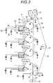
- An embodiment of the electrophotographic member for use as a conductive roller is illustrated in each of FIG. 1A, FIG. 1B and FIG. 1C .
- the conductive roller 1 may include a conductive mandrel 2 and an elastic layer 3 disposed on the outer periphery thereof.
- the elastic layer 3 is an electro-conductive layer made of a resin synthesized from an ion conducting agent and a compound being able to react with the ion conducting agent.
- a surface layer 4 may be formed on the surface of the elastic layer 3.
- the electro-conductive layer may be used in any of the elastic layer 3 and the surface layer 4.
- a three-layer structure having an intermediate layer 5 between an elastic layer 3 and a surface layer 4, or a multi-layer structure having a plurality of intermediate layers 5 may be employed.
- the electro-conductive layer may be used in any of the elastic layer 3, the intermediate layer 5 and the surface layer 4.
- the electrophotographic member of the present invention may be used as a charging member or a developing member.
- the conductive roller may be used as a charging roller or a developing roller.
- a mandrel 2 functioning as an electrode and a supporting member of a conductive roller 1 is made of conductive material such as a metal or alloy, e.g. aluminum, copper alloy and stainless steel; iron plated with chromium or nickel; and synthesized resin having conductivity; which may be solid or hollow.
- conductive material such as a metal or alloy, e.g. aluminum, copper alloy and stainless steel; iron plated with chromium or nickel; and synthesized resin having conductivity; which may be solid or hollow.
- a cation means a cation part contained in an ion conducting agent for synthesizing the resin to be contained in an electro-conductive layer, in a state before reacting with a compound being able to react with a hydroxyl group.
- a cationic structure means a portion of the resin contained in the electro-conductive layer synthesized from the ion conducting agent and the compound being able to react with the ion conducting agent.
- the cationic structure is a residue derived from the ion conducting agent, bonding to other portions of the resin at a plurality of sites.
- the electro-conductive layer of the present invention includes a resin synthesized from the ion conducting agent and the compound being able to react with the ion conducting agent.
- the ion conducting agent includes an anion and a cation having at least three hydroxyl groups.
- the compound being able to react with the ion conducting agent reacts with the hydroxyl groups which the cation of the ion conducting agent has.
- the anion is at least one selected from the group consisting of a fluorinated sulfonate anion, a fluorinated carboxylate anion, a fluorinated sulfonylimide anion, a fluorinated sulfonylmethide anion, a dicyanamide anion, a fluorinated alkylfluoroborate anion, a fluorinated phosphate anion, a fluorinated antimonate anion, a fluorinated arsenate anion, and bis(oxalato)borate anion.
- the electro-conductive layer of the present invention includes the resin having the cationic structure in the branched portion of a polymer chain and at least one anion selected from the group consisting of a fluorinated sulfonate anion, a fluorinated carboxylate anion, a fluorinated sulfonylimide anion, a fluorinated sulfonylmethide anion, a dicyanamide anion, a fluorinated alkylfluoroborate anion, a fluorinated phosphate anion, a fluorinated antimonate anion, a fluorinated arsenate anion, and bis(oxalato)borate anion, wherein the branched portion has at least one cationic structure selected from the group consisting of the formulae (1) to (13) and (16) to (18) defined below.
- the ion conducting agent and the compound being able to react with the ion conducting agent of the present invention are essential materials to obtain a resin having a cationic structure in the branched portion of a polymer chain.
- the compound being able to react with a hydroxyl group means a compound including two or more functional groups which react with a hydroxyl group in a molecule.
- the compound being able to react with a hydroxyl group may react not only with the hydroxyl group of the ion conducting agent but also with the hydroxyl group of a polyol or another compound in an electro-conductive layer.
- Examples of the compound being able to react with a hydroxyl group include an isocyanate compound, a carboxylic acid compound, an epoxide compound and a melamine compound.
- isocyanate compound examples include: an aliphatic polyisocyanate such as ethylene diisocyanate, and 1,6-hexamethylene diisocyanate (HDI); alicyclic polyisocyanate such as isophorone diisocyanate (IPDI), cyclohexane-1,3-diisocyanate, and cyclohexane-1,4-diisocyanate; an aromatic isocyanate such as 2,4-tolylene diisocyanate, 2,6-tolylene diisocyanate (TDI), 4,4'-diphenylmethane diisocyanate (MDI), polymeric diphenylmethane diisocyanate, xylylene diisocyanate, and naphthalene diisocyanate; copolymers thereof; and isocyanurate compounds such as isocyanurate forms, TMP adduct forms, and biuret forms and blocked forms thereof.
- IPDI isophorone diisocyan
- carboxylic acid compound examples include: an aliphatic dicarboxylic acid such as adipic acid, sebacic acid, malonic acid, 1,4-cyclohexane dicarboxylic acid, and hexahydroisophthalic acid; and an aromatic dicarboxylic acid such as orthophthalic acid, isophthalic acid and terephthalic acid.
- epoxide compound examples include an aliphatic diepoxide such as 1,4-butane diol diglycidyl ether; and an aromatic diepoxide such as bisphenol-A diglycidyl ether.
- Examples of the melamine compound for use include a methylated-type melamine, butylated-type melamine, imino-type melamine, methylbutyl-mixed melamine and a methylol-type melamine.
- an aromatic isocyanate such as tolylene diisocyanate, diphenylmethane diisocyanate, and polymeric diphenylmethane diisocyanate is more preferably used in terms of the excellent deformation recovery of a resin to be obtained.
- the resin may be synthesized with further addition of a polyol other than the ion conducting agent for further improving the flexibility of the electro-conductive layer.
- the polyol has a plurality of hydroxyl groups in a molecule, and the hydroxyl groups react with the compound being able to react with hydroxyl groups.
- examples of the polyol include polyether polyol and polyester polyol, though not specifically limited.
- examples of the polyether polyol include polyethylene glycol, polypropylene glycol and polytetramethylene glycol.
- polyester polyol which is obtained by the condensation reaction of a diol component such as 1,4-butanediol, 3-methyl-1,4-pentanediol, neopentyl glycol; or triol component such as trimethylolpropane; with dicarboxylic acid such as adipic acid, phthalic anhydride, terephthalic acid, hexahydroxyphthalic acid.
- diol component such as 1,4-butanediol, 3-methyl-1,4-pentanediol, neopentyl glycol
- triol component such as trimethylolpropane
- dicarboxylic acid such as adipic acid, phthalic anhydride, terephthalic acid, hexahydroxyphthalic acid.
- the polyether polyol and the polyester polyol may be subjected to chain-growth reaction to form into a prepolymer with an isocyanate such as 2,4-tolylene diisocyanate (TDI), 1,4-diphenylmethane diisocyanate (MDI), and isophorone diisocyanate (IPDI), in advance and as needed.
- an isocyanate such as 2,4-tolylene diisocyanate (TDI), 1,4-diphenylmethane diisocyanate (MDI), and isophorone diisocyanate (IPDI
- a general-purpose resin other than the resin of the present invention, a rubber material, a compounding agent, a conductivity imparting agent, a non-conductive filler, a cross-linking agent, and a catalyst may be added to the electro-conductive layer on an as needed basis, to an extent not to impair the effects of the present invention.
- the resin to be added include an epoxy resin, a urethane resin, a urea resin, an ester resin, an amide resin, an imide resin, an amide-imide resin, a phenol resin, a vinyl resin, a silicone resin and a fluorine resin, though not specifically limited.
- the rubber material examples include an ethylene-propylene-dien copolymer rubber, an acrylonitrile-butadiene rubber, a chloroprene rubber, a natural rubber, an isoprene rubber, a styrene-butadiene rubber, a silicone rubber, an epichlorohydrin rubber, and a urethane rubber.
- the compounding agent include a filler, a softener, a processing aid, tackifier, an antitack agent, and a foaming agent, which are widely used in resins.
- Examples of the conductivity imparting agent for use include fine particles of: carbon black; a conductive metal such as aluminum and copper; and a conductive metal oxide such as conductive zinc oxide, conductive tin oxide, and conductive titanium oxide.
- Examples of the non-conductive filler include silica, quartz powder, titanium oxide and calcium carbonate.
- Examples of the cross-linking agent include tetraethoxysilane, di-t-butylperoxide, 2,5-dimethyl-2,5-di(t-butylperoxy)hexane, and dicumylperoxide, though not specifically limited.
- fine particles may be added to the electro-conductive layer for control of the roughness.
- the fine particles for control of the roughness can have a volume mean particle diameter of 3 to 20 ⁇ m so as to obtain a developing roller excellent in transporting a developer.
- the amount of the fine particles to be added to the electro-conductive layer can be 1 to 50 parts by mass relative to 100 parts by mass of the resin solid content of the electro-conductive layer, for not impairing the effects of the present invention.
- the fine particles for use in control of the roughness include fine particles of a polyurethane resin, a polyester resin, a polyether resin, a polyamide resin, an acrylic resin and a phenol resin.
- Examples of the method for forming the electro-conductive layer include spraying of a coating material, immersion, and roll coating, though not specifically limited.
- the immersion coating method in which a coating material overflows from the upper end of an immersion tank as described in Japanese Patent Laid-Open No. S57-5047 is simple and excellent in production stability as a method for forming an electro-conductive layer.
- a known method may be applied to the conductive roller.
- Examples of the method include: forming by co-extruding the materials for the mandrel and the electro-conductive layer; and feeding a liquid material for forming an electro-conductive layer in a mold equipped with a cylindrical pipe, pieces disposed at both ends of the pipe for holding a mandrel, and the mandrel, so as to be heat-cured.
- the ion conducting agent for use in an electro-conductive layer has a cation and an anion.
- the cation has three or more hydroxyl groups in a molecule.
- the cation includes a cation skeleton and a substituent having a hydroxyl group.
- the cation may further have a substituent having no hydroxyl group.
- the substituent having a hydroxyl group and the substituent having no hydroxyl group each bond to a cation skeleton.
- Examples of the cation skeleton include: an acyclic cation such as a quaternary ammonium cation, a sulfonium cation, a phosphonium cation; and a nitrogen-containing heterocyclic cation such as an imidazolium cation, a pyridinium cation, a pyrrolidinium cation, a piperidinium cation, a pyrazolium cation, a morpholinium cation, a pyrazolinium cation, a hydroimidazolium cation, a triazolium cation, a pyridazinium cation, a pyrimidinium cation, a pyrazinium cation, a thiazolium cation, an oxazolium cation, an indolium cation, a quinolinium cation, an isoquinolinium cation and
- an electro-conductive layer using an ion conducting agent having a nitrogen atom in the cation skeleton such as a quaternary ammonium cation and a nitrogen-containing heterocyclic cation is preferred in terms of achieving relatively high conductivity in comparison with an electro-conductive layer using an ion conducting agent having no nitrogen atom in the cation skeleton (e.g. a sulfonium cation and a phosphonium cation).
- the ion conducting agent having the quaternary ammonium cation or the imidazolium cation allows the electro-conductive layer excellent in conductivity to be produced even with a small amount added.
- the addition of the ion conducting agent having the quaternary ammonium cation and the imidazolium cation to the electro-conductive layer is, therefore, particularly preferred, in terms of achieving extremely small reduction in the deformation recovery of an electrophotographic member after a long-term storage under a high temperature and high humidity environment.
- the cation of the ion conducting agent can be a quaternary ammonium cation having at least three hydroxyl groups, a nitrogen-containing heterocyclic cation having at least three hydroxyl groups, or an imidazolium cation having at least three hydroxyl groups.
- the cation includes two or more substituents having a hydroxyl group.
- substituted having a hydroxyl group means a substituent having one or more hydroxyl groups.
- the substituent having a hydroxyl group is selected such that at least three hydroxyl groups bond to one cation skeleton. It is more preferred as the number of hydroxyl groups increases.
- the substituent having a hydroxyl group may have the hydroxyl group directly bonding to a cation skeleton, such as hydroxypyridinium and hydroxyimidazolium; or may have the hydroxyl group bonding to the cation skeleton through a linking group such as a hydrocarbon group and an alkoxy group.
- the hydroxyl group bonding to the cation skeleton through the linking group is preferred due to a relatively high reactivity of the hydroxyl group.
- Examples of the linking group for bonding the hydroxyl group to the cation skeleton include the hydrocarbon group, a substituent having an alkylene ether group, and a substituent having a branched structure.
- the hydrocarbon group may be a hydrocarbon group having 1 to 30 carbon atoms such as a methylene group, an ethylene group, a propylene group, a butylene group, a pentylene group, a hexylene group and a phenylene group, and may have a hetero atom and another functional group having no hydroxyl group (e.g.
- a hydrocarbon group having 1 to 30 carbon atoms having 1 to 30 carbon atoms, a halogen group such as fluorine, chlorine, bromine and iodine, an alkoxy group such as a methoxy group and an ethoxy group, a substituent including a hetero atom such as an amide group and a cyano group, and a haloalkyl group such as trifluoromethyl group).
- a hydrocarbon group having 1 to 30 carbon atoms a halogen group such as fluorine, chlorine, bromine and iodine, an alkoxy group such as a methoxy group and an ethoxy group, a substituent including a hetero atom such as an amide group and a cyano group, and a haloalkyl group such as trifluoromethyl group).
- substituent having an alkylene ether group examples include an alkylene ether group having a degree of polymerization of 1 to 10 such as oligo(ethylene glycol), oligo(propylene glycol) and oligo(tetramethylene glycol).
- the substituent having a branched structure is a substituent having one cation skeleton to which a plurality of hydroxyl groups bond through a plurality of the linking groups, with carbon atoms or nitrogen atoms as the branch points, and examples thereof include a 1,2-propanediol group, a [bis(2-hydroxyethyl)amino]ethylene group, and a 2,2-bis(hydroxymethyl)-3-hydroxypropyl group.
- the cation of the ion conduction agent may include, in addition to a substituent having a hydroxyl group, one or more substituents having no hydroxyl group (e.g. a hydrocarbon group having 1 to 30 carbon atoms, a halogen group such as fluorine, chlorine, bromine and iodine, an alkoxy group such as a methoxy group and an ethoxy group, a substituent including a hetero atom such as an amide group and a cyano group, and a haloalkyl group such as a trifluoromethyl group).
- substituents having no hydroxyl group e.g. a hydrocarbon group having 1 to 30 carbon atoms, a halogen group such as fluorine, chlorine, bromine and iodine, an alkoxy group such as a methoxy group and an ethoxy group, a substituent including a hetero atom such as an amide group and a cyano group, and a halo
- the anion of the ion conducting agent is selected from the group consisting of a fluorinated sulfonate anion, a fluorinated carboxylate anion, a fluorinated sulfonylimide anion, a fluorinated sulfonylmethide anion, a fluorinated alkylfluoroborate anion, a fluorinated phosphate anion, a fluorinated antimonate anion, a fluorinated arsenate anion, a dicyanamide anion, and a bis(oxalato)borate anion.
- fluorinated sulfonate anion examples include a trifluoromethane sulfonate anion, a fluoromethane sulfonate anion, a perfluoroethyl sulfonate anion, a perfluoropropyl sulfonate anion, a perfluorobutyl sulfonate anion, a perfluoropentyl sulfonate anion, a perfluorohexyl sulfonate anion, and a perfluorooctyl sulfonate anion.
- fluorinated carboxylate anion examples include a trifluoroacetate anion, a perfluoropropionate anion, a perfluorobutyrate anion, a perfluorovalerate anion and a perfluorocaproate anion.
- fluorinated sulfonylimide anion examples include an anion such as a trifluoromethanesulfonylimide anion, a perfluoroethylsulfonylimide anion, a perfluoropropylsulfonylimide anion, a perfluorobutylsulfonylimide anion, a perfluoropentylsulfonylimide anion, a perfluorohexylsulfonylimide anion, a perfluorooctylsulfonylimide anion, a fluorosulfonylimide anion, and a cyclic anion such as a cyclo-hexafluoropropane-1,3-bis(sulfonyl)imide anion.
- an anion such as a trifluoromethanesulfonylimide anion, a perfluoroethylsulfony
- fluorinated sulfonylmethide anion examples include a trifluoromethane sulfonylmethide anion, a perfluoroethyl sulfonylmethide anion, a perfluoropropyl sulfonylmethide anion, a perfluorobutyl sulfonylmethide anion, a perfluoropentyl sulfonylmethide anion, a perfluorohexyl sulfonylmethide anion, and a perfluorooctyl sulfonylmethide anion.
- fluorinated alkyl fluoroborate anion examples include a trifluoromethyl trifluoroborate anion and a perfluoroethyl trifluoroborate anion.
- fluorinated phosphate anion examples include a hexafluorophosphate anion, a tris-trifluoromethyl-trifluorophosphate anion, and a tris-perfluoroethyl-trifluorophosphate anion.
- fluorinated antimonate anion examples include a hexafluoroantimonate anion and a trifluoromethyl-pentafluoroantimonate anion.
- fluorinated arsenate anion examples include a hexafluoroarsenate anion and a trifluoromethyl-pentafluoroarsenate anion.
- Examples of the other anion include a dicyanamide anion and a bis(oxalato)borate anion.
- an anion having an electron drawing fluorinated sulfonyl group such as the fluorinated sulfonate anion, a fluorinated sulfonylimide anion, and a fluorinated sulfonylmethide anion is preferred as the anion of an ion conducting agent, in terms of achieving a desired conductivity with a relatively small amount of content in an electro-conductive layer.
- the amount of the ion conducting agent blended can be 0.01 parts by mass or more and 20 parts by mass or less relative to 100 parts by mass of an electro-conductive layer. With an amount of 0.01 parts by mass or more, an electro-conductive layer having high conductivity can be obtained, and with an amount of 20 parts by mass or less, the electro-conductive layer particularly excellent in deformation recovery can be obtained.
- the resin of the present invention is synthesized from an ion conducting agent and a compound being able to react with the ion conducting agent.
- the ion conducting agent includes an anion and a cation having at least three hydroxyl groups.
- the compound being able to react with the ion conducting agent is the compound being able to react with a hydroxyl group of the cation of the ion conducting agent.
- the resin of the present invention is obtained by a reaction of an ion conducting agent having at least three hydroxyl groups and a compound being able to react with an ion conducting agent.
- the resin of the present invention includes at least one cationic structure selected from the group consisting of the following Formulas (1) to (13) .
- X 1 to X 3 each independently represent a structure including a portion bonding to a resin through a bond selected from the group consisting of an ether bond, an ester bond and a urethane bond.
- R 1 represents one selected from the group consisting of the following (a) to (c) :
- R 2 and R 3 each independently represent one selected from the group consisting of the following (a) to (c):
- X 4 represents a structure including a portion bonding to a resin through a bond selected from the group consisting of an ether bond, an ester bond and a urethane bond.
- Y 1 represents one selected from the group consisting of Ya and Yb in the following Formulas (14) and (15).
- a 1 and A 2 each independently represent a hydrocarbon group or an alkylene ether group.
- X 17 to X 20 each independently represent a structure including a portion bonding to a resin through a bond selected from the group consisting of an ether bond, an ester bond and a urethane bond.
- Y 2 and Y 3 each represent one selected from the group consisting of Ya and Yb in Formulas (14) and (15).
- R 4 and R 5 each independently represent one selected from the group consisting of the following (a) to (c) :
- Y 4 represents one selected from the group consisting of Ya and Yb in Formulas (14) and (15).
- R 6 represents a hydrocarbylene group having 1 to 3 carbon atoms, and may include a hetero atom.
- the hydrocarbylene group is herein defined as a divalent hydrocarbon group. Specific examples thereof include a methylene group (-CH 2 -), an ethylene group (-CH 2 CH 2 -), and propane-1,3-diyl group (-CH 2 CH 2 -CH 2 -).
- R 7 represents a structure including a portion bonding to a resin through a bond selected from the group consisting of an ether bond, an ester bond and a urethane bond.
- Z 1 represents one selected from the group consisting of a hydrogen atom and a hydrocarbon group having 1 to 30 carbon atoms.
- R 8 represents a hydrocarbylene group having 1 to 3 carbon atoms, and may include a hetero atom.
- R 9 and R 10 each represent a structure including a portion bonding to a resin through a bond selected from the group consisting of an ether bond, an ester bond and a urethane bond, or one selected from the group consisting of Ya and Yb in Formulas (14) and (15).
- R 11 and R 12 each independently represent one selected from the group consisting of the following (a) to (c), provided that at least one of R 11 and R 12 is (c) :
- R 13 represents a hydrocarbylene group having 3 to 5 carbon atoms, and may include an oxygen atom or a sulfur atom.
- X 5 to X 7 each represent a structure including a portion bonding to a resin through a bond selected from the group consisting of an ether bond, an ester bond and a urethane bond.
- R 14 represents a hydrocarbylene group having 3 to 5 carbon atoms, and may include an oxygen atom or a sulfur atom.
- R 15 and R 16 each independently represent one selected from the group consisting of the following (a) to (c), provided that at least one of R 15 and R 16 is (c) :
- Y 5 represents one selected from the group consisting of Ya and Yb in Formulas (14) and (15).
- R 16 is absent.
- R 17 represents a hydrocarbylene group having 3 to 5 carbon atoms, and may include an oxygen atom or a sulfur atom.
- R 18 represents one selected from the group consisting of the following (a) to (c):
- Y 6 and Y 7 each independently represent one selected from the group consisting of Ya and Yb in Formulas (14) and (15) .
- R 19 represents a hydrocarbylene group having 1 to 3 carbon atoms, and may include a hetero atom.
- R 20 and R 22 each independently represent a structure including a portion bonding to a resin through a bond selected from the group consisting of an ether bond, an ester bond and a urethane bond, or one selected from the group consisting of Ya and Yb in Formulas (14) and (15), provided that at least one of R 20 and R 22 is one selected from the group consisting of Ya and Yb.
- R 21 represents one selected from the group consisting of the following (a) to (c):
- Z 2 represents one selected from the group consisting of a hydrogen atom and a hydrocarbon group having 1 to 30 carbon atoms.
- X 8 to X 10 each represent a structure including a portion bonding to a resin through a bond selected from the group consisting of an ether bond, an ester bond and a urethane bond.
- R 23 represents one selected from the group consisting of the following (a) to (c):
- X 11 represents a structure including a portion bonding to a resin through a bond selected from the group consisting of an ether bond, an ester bond and a urethane bond.
- Y 8 represents one selected from the group consisting of Ya and Yb in Formulas (14) and (15).
- R 24 and R 25 each independently represent one selected from the group consisting of the following (a) to (c):
- X 12 to X 14 each independently represent a structure including a portion bonding to a resin through a bond selected from the group consisting of an ether bond, an ester bond and a urethane bond.
- Y 9 represents one selected from the group consisting of Ya and Yb in Formulas (14) and (15).
- R 26 and R 27 each independently represent one selected from the group consisting of the following (a) to (c), provided that at least one of R 26 and R 27 is (c) :
- a 1 and A 2 each represent a hydrocarbon group or an alkylene ether group, as described above.
- a 1 and A 2 each independently have a shortest length of 9 atoms or less.
- a 1 and A 2 representing a hydrocarbon group for example, a nonylene group meets the requirement.
- a 1 and A 2 representing an alkylene ether group a polytetramethylene glycol group with a degree of polymerization of 2, or a polyethylene glycol group with a degree of polymerization of 3 meets the requirement.
- a 1 and A 2 may include another functional group having no hydroxyl group (e.g.
- a hydrocarbon group having 1 to 30 carbon atoms having 1 to 30 carbon atoms, a halogen group such as fluorine, chlorine, bromine and iodine, an alkoxy group such as a methoxy group and an ethoxy group, a substituent including a hetero atom such as an amide group and a cyano group, and a haloalkyl group such as trifluoromethyl group).
- a hydrocarbon group having 1 to 30 carbon atoms a halogen group such as fluorine, chlorine, bromine and iodine, an alkoxy group such as a methoxy group and an ethoxy group, a substituent including a hetero atom such as an amide group and a cyano group, and a haloalkyl group such as trifluoromethyl group).
- the electro-conductive layer may include a cationic structure represented by, for example, at least one selected from the group consisting of the following Formulas (16) to (18).
- X 15 and X 16 each independently represent a structure including a portion bonding to a resin through a bond selected from the group consisting of an ether bond, an ester bond and a urethane bond.
- R 28 to R 30 each independently represent one selected from the group consisting of the following (a) to (c), provided that at least one of R 28 to R 30 is (c) :
- Y 10 represents one selected from the group consisting of Ya and Yb in Formulas (14) and (15).
- Z 3 , Z 4 and Z 5 each independently represent a hydrogen atom or a hydrocarbon group having 1 to 30 carbon atoms.
- R 31 represents a structure including a portion bonding to a resin through a bond selected from the group consisting of an ether bond, an ester bond, and a urethane bond, or one selected from the group consisting of Ya and Yb in Formulas (14) and (15) .
- a 1 and A 2 each independently represent a hydrocarbon group or an alkylene ether group.
- X 17 to X 20 each independently represent a structure including a portion bonding to a resin through a bond selected from the group consisting of an ether bond, an ester bond and a urethane bond.
- Y 11 represents one selected from the group consisting of Ya and Yb in Formulas (14) and (15).
- R 32 represents one selected from the group consisting of the following (a) to (c), or one selected from the group consisting of Ya and Yb in Formulas (14) and (15):
- R 33 to R 35 each independently represent one selected from the group consisting of the (a) to (c), provided that at least one of R 33 to R 35 is (c) .
- deformation recovery means the properties of an electro-conductive layer to recover deformation after the passage of a predetermined period after removal of the stress applied to the electro-conductive layer left standing in a high temperature and high humidity environment for a long period under stressed state (i.e. in a state that the electro-conductive layer is deformed).
- the amount of residual deformation is reduced when an electrophotographic member having the electro-conductive layer is left standing in a high temperature and high humidity environment for a long period.
- the present inventors presume the reason that use of the cation and the anion of the present invention has remarkable effects on the improvement in the deformation recovery of an electro-conductive layer is as follows.
- the resin contained in an electro-conductive layer including a polar functional group such as a carboxy group, a urethane group, an ester group, a hydroxyl group and an amino group allows the polar functional groups to mutually form pseudo cross-linking points due to interaction such as hydrogen bonding. It is presumed that the pseudo cross-linking points become the basis for keeping the deformation recovery.
- the cationic structure contained in the resin bonds to a polymer chain at two sites so as to be integrated into the main chain of a polymer.
- the free motion frequency of the cationic structure integrated into a main chain is limited to an extent, the movability can be kept to an extent due to the bonds to a polymer chain at only two sites.
- the cationic structure in this state approaches a polar functional group (e.g. a carboxy group, a urethane group, an ester group, a hydroxyl group and an amino group) in the resin, the negatively polarized portion of the polar functional group and the cationic structure having a positive charge are attracted to each other.
- a polar functional group e.g. a carboxy group, a urethane group, an ester group, a hydroxyl group and an amino group
- the cationic structure contained in the resin bonds to a polymer chain at three or more sites.
- the free motion frequency of the cationic structure is, therefore, further limited in comparison with the preceding case, causing difficulty for the cationic structure in approaching the polar functional group in the resin.
- the bulky cationic structure obstructs the movement of the cationic structure, causing difficulty for the cationic structure in approaching the polar functional group.
- an anion to easily reduce a proton, having a high proton affinity such as a halide anion, a sulfate anion and a nitrate anion, easily causes an interaction between the anion and the proton which the polar functional group has.
- the proton which a polar functional group has e.g. the proton located at the ⁇ position relative to the carbonyl group in an ester group, and the proton which a urethane group, an amino group or a hydroxyl group has
- the proton which a polar functional group has is positively charged due to polarization, causing interaction with a negatively polarized portion of the polar functional group.
- the anions of the present invention have extremely high chemical stability and low proton affinity, hence the anions hardly reduce the proton.
- both of the cation and the anion of the present invention are the ones not reducing the interaction between the polar functional groups of the resin of an electro-conductive layer. It is presumed that use of the ion conducting agent of the present invention therefore can suppress reduction in the deformation recovery of the electro-conductive layer.
- the electrophotographic member of the present invention can be used in an electrophotographic member such as a charging roller, a developing roller, a transferring roller, a cleaning blade.
- the developer may be of a magnetic type or a nonmagnetic type, and may include one component or two components.
- the developing apparatus may be of a non-contact type or a contact type.
- FIG. 2 is a cross-sectional view illustrating the process cartridge of the present invention.
- the process cartridge 17 illustrated in FIG. 2 includes a developing roller 16, a developing blade (toner amount regulating blade) 21, electrophotographic photosensitive member 18, a cleaning blade 26, a waste toner accommodation container 25, and a charging roller 24, which are integrated.
- the process cartridge is adapted to be detachably attached to the main body of an electrophotographic image forming apparatus.
- the developing apparatus 22 includes a toner container 20 filled with a toner 15.
- the toner 15 contained in the toner container 20 is supplied to the surface of the developing roller 16 with a toner supply roller 19, and a toner layer having a predetermined thickness is formed on the surface of the developing roller 16 with the developing blade 21.
- FIG. 3 is a cross-sectional view illustrating an electrophotographic apparatus in which the electrophotographic member of the present invention is used as developing roller 16.
- a process cartridge 17 including a photosensitive member 18, a cleaning blade 26, a waste toner accommodation container 25 and a charging roller 24 is also detachably mounted.
- the developing apparatus 22 may be detachably mounted as a stand-alone unit, or may be integrally formed together with the process cartridge 17 so as to be detachably mounted in one united body.
- the developing apparatus 22, the photosensitive member 18, the cleaning blade 26, the waste toner accommodation container 25 and the charging roller 24 may be disposed in the electrophotographic apparatus main body.
- the process cartridge of the present invention may be of any type, as long as the process cartridge has at least one of the charging roller 24 and the developing roller 16, being detachably mounted to an electrophotographic apparatus main body.
- the photosensitive member 18 rotates in the arrow direction so as to be uniformly charged with the charging roller 24 for charging the photosensitive member 18.
- An electrostatic latent image is then formed on the surface of the photosensitive member 18 with a laser beam 23 from an exposure unit for forming an electrostatic latent image on the photosensitive member 18.
- the electrostatic latent image is developed with the toner 15 imparted with the developing apparatus 22 disposed in contact with the photosensitive member 18, so as to be visualized as a toner image.
- the visualized toner image on the photosensitive member 18 is transferred to a paper 34 as recording medium with a transferring roller 29 as transferring member.
- the paper 34 is fed into the apparatus through a paper feed roller 35 and an adsorption roller 36, and transported between the photosensitive member 18 and the transferring roller 29 with a transfer transporting belt 32 in an endless belt form.
- the transfer transporting belt 32 is operated with a driven roller 33, a driving roller 28 and a tension roller 31.
- a voltage is applied to the transfer roller 29 and the adsorption roller 36 from a bias power supply 30.
- the paper 34 with the transferred toner image is subjected to fixation treatment with a fixation apparatus 27, and ejected outside the apparatus for completion of the printing operation.
- the toner remaining on the photosensitive member 18 without being transferred to the paper 34 is scraped off with a cleaning blade 26 so as to be accommodated in the waste toner accommodation container 25.
- the developing apparatus 22 includes a toner container 20 which accommodates toner as one-component developer, and a developing roller 16 as developer carrier which is positioned at an opening extending in the longitudinal direction of the toner container 20 and disposed opposite to the photosensitive member 18.
- the developing apparatus 22 develops an electrostatic latent image on the photosensitive member 18 and visualizes the image.
- a voltage is applied to each of the developing roller 16 and the developing blade 21 from the bias power supply 30.
- a core metal made of SUS 304 having a diameter of 6 mm, a total length of 278.9 mm was coated with a primer (trade name: DY35-051; manufactured by Dow Corning Toray Co., Ltd.), and baked in an oven heated at a temperature of 180°C for 20 minutes so as to make a mandrel.
- a primer trade name: DY35-051; manufactured by Dow Corning Toray Co., Ltd.
- the mandrel thus prepared was disposed in a mold, and an addition type silicone rubber composition including a mixture of the following materials was injected into a cavity formed in the mold.
- the adhesive for use was of a conductive hot-melt type.
- a roll coater was used for the coating.
- a die having an inner diameter of 16.5 mm was mounted to a cross head extruder having a mandrel supply mechanism and an unvulcanized rubber roller discharge mechanism.
- the temperature of the extruder and the die (cross head) was then adjusted to 80°C, and the transportation speed of the conductive mandrel was adjusted to 60 mm/sec.
- the unvulcanized rubber composition was supplied from the extruder under the conditions, so that the conductive mandrel was coated with the unvulcanized rubber composition to make an elastic layer in the cross head.
- the coated mandrel was fed in a hot air vulcanization furnace at 170°C and heated for 60 minutes.
- An ion conducting agent can be obtained by synthesizing a precursor using a one-step or a plurality of steps of a known nucleophilic substitution reaction such as Kohlutkin reaction and then performing a known ion exchange reaction.
- examples of the nucleophile for use include a compound having a nucleophilic hetero atom such as primary to tertiary amine compounds, an imidazole compound, a pyridine compound, a piperidine compound, a pyrrolidine compound, a morpholine compound, a pyrazole compound, a sulfide compound and a phosphine compound.
- a nucleophilic hetero atom such as primary to tertiary amine compounds, an imidazole compound, a pyridine compound, a piperidine compound, a pyrrolidine compound, a morpholine compound, a pyrazole compound, a sulfide compound and a phosphine compound.
- examples of the electrophile for use include a halogenated alkyl compound of which hydroxyl group is substituted.
- examples of the alkali metal salt for use in the ion exchange reaction include an alkali metal salt which contains the anion of the present invention such as a lithium fluorinated alkyl sulfonate salt and a potassium fluorinated alkylsulfonylimide salt.
- a target ion conducting agent can be synthesized with a combination of known methods, by changing the nucleophile and the electrophile for use in a nucleophilic reaction, and the alkali metal salt for use in an ion exchange reaction into a desired combination.
- a nucleophile N-1 (dibutylamine) (manufactured by Tokyo Chemical Industry Co., Ltd.) in an amount of 24.2 g was dissolved in 50 ml of acetonitrile.
- An electrophile Q-1 (4-bromo-1-butanol) (manufactured by Tokyo Chemical Industry Co., Ltd.) in amount of 68.3 g was added to the solution at room temperature, which was then heated and refluxed at 90°C for 72 hours. Subsequently the solvent was distilled away under reduced pressure. The obtained concentrate was washed with diethyl ether, and the supernatant liquid was removed by decantation. The washing and the decantation was repeated three times, so that a residue was obtained.
- the obtained residue is a compound having a bromide ion.
- N-16 NEWPOL NP-400 NP-400 manufactured by Sanyo Chemical Industries, Ltd.
- N-6 1-Piperidine ethanol manufactured by Tokyo Chemical Industry Co., Ltd.
- N-17 4-Amino-1-butanol manufactured by Tokyo Chemical Industry Co., Ltd.
- N-7 4-Piperidine ethanol manufactured by Tokyo Chemical Industry Co., Ltd.
- N-18 Butylamine manufactured by Tokyo Chemical Industry Co., Ltd.
- N-8 Morpholine manufactured by Tokyo Chemical Industry Co., Ltd.
- N-19 3-Amino-1,2-propanediol manufactured by Tokyo Chemical Industry Co., Ltd.
- N-9 Pyrazole manufactured by Tokyo Chemical Industry Co., Ltd.
- N-20 1-(2-Hydroxyethyl)imidazole manufactured by Sigma-Aldrich Co.
- N-10 2-2'-Thiodiethanol manufactured by Tokyo Chemical Industry Co., Ltd.
- N-21 (lH-Imidazol-2-yl)methanol manufactured by Sigma-Aldrich Co. LLC.
- N-11 Tris(hydroxymethyl)phosphi ne manufactured by Sigma-Aldrich Co.
- Ion conducting agents 1-4, 1-5, 1-7, 1-9, 2-2 to 2-4, 2-6, 2-7, 3-1, 3-2, 4-1, 4-2, 5-1, 5-2, 8-1, 8-2 and 9-2 were obtained in the same way as in the synthesis of the ion conducting agent 1-3, except that the types and the amounts of the nucleophile, the electrophile and the anion exchange salt as raw materials blended were changed as described in Tables 1 to 4.
- An ion conducting agents 2-3 was obtained as a chloride salt without anion exchange.
- a benzene layer was washed with water and dried. Benzene was then distilled away, so that a tertiary amine compound was obtained as a yellow viscous liquid. Subsequently the obtained tertiary amine compound was dissolved in 300 ml of acetonitrile.
- An electrophile Q-4 (3-chloro-1,2-propanediol) (manufactured by Tokyo Chemical Industry Co., Ltd.) for quaternization in an amount of 21.2 g was added to the solution at room temperature, which was then heated and refluxed at 90°C for 72 hours. The solvent was then distilled away under reduced pressure. The obtained concentrate was washed with diethyl ether, and the supernatant liquid was removed by decantation. The procedure was repeated three times, so that a residue was obtained. The obtained residue is a compound having a chloride ion.
- the obtained residue was dissolved in 20 ml of dichloromethane.
- An anion exchange salt A-1 lithium trifluoromethanesulfonate (manufactured by Wako Pure Chemical Industries, Ltd.) in an amount of 22.1 g dissolved in 20 ml of water was added to the solution, which was stirred at room temperature for 24 hours.
- the obtained solution was separated to obtain an organic layer.
- the organic layer was separated with water two times.
- Dichloromethane was distilled away under reduced pressure, so that an ion conducting agent 1-6 was obtained, having trifluoromethane sulfonate anion as the anion.
- Ion conducting agents 1-10, 1-11, 2-5, 6-1 and 7-1 were obtained by the same way as in the synthesis of the ion conducting agent 1-6, except that the type and the amounts of the nucleophile, the electrophile, and the anion exchange salt as raw materials blended were changed as described in Table 5.
- Potassium carbonate in an amount of 14.8 g was added to 100 mL of acetonitrile solution of 15.4 g of a nucleophile N-5 (3-methylamino-1-propanol) (manufactured by Tokyo Chemical Industry Co., Ltd.) and 16.1 g of 4-chloromethyl-2,2-dimethyl-1,3-dioxolane. The solution was then heated and refluxed at 90°C for 18 hours. After completion of the reaction, the solution was cooled to room temperature, and the precipitated solid was filtered and washed with 300 mL of acetonitrile. The filtrate was concentrated under reduced pressure and then purified with silica gel column chromatography, so that 5.7 g of an intermediate 1 was obtained.
- a nucleophile N-9 (3-amino-1,2-propanediol) (manufactured by Tokyo Chemical Industry Co., Ltd.) in an amount of 2.02 g was dissolved in 20 ml of benzene (manufactured by Kanto Chemical Co., Inc.).
- An electrophile Q-7 tetraethylene glycol p-toluenesulfonate (manufactured by Sigma-Aldrich Co. LLC.) in an amount of 11.6 g dissolved in 10 ml of benzene was dropwisely added into the solution, which was then heated and refluxed at 85°C for 42 hours.
- reaction was performed with stirring for further 2 hours, so that a reaction mixture was obtained.
- the obtained reaction mixture was diluted with addition of diethyl ether.
- An ammonium chloride aqueous solution was added to the diluted product for extraction, so that a tertiary ammonium chloride was obtained.
- the obtained tertiary ammonium chloride was dissolved in 5 ml of dichloromethane.
- An anion exchange salt A-8 (potassium heptafluoropropane sulfonate (manufactured by Mitsubishi Materials Electronic Chemicals Co., Ltd.) in amount of 7.04 g dissolved in 5 ml of water was then added to the solution, which was then stirred at room temperature for 24 hours. The produced solution was separated to obtain an organic layer. The organic layer was separated with water two times, and then dichloromethane was distilled away under reduced pressure. An ion conducting agent 1-12 was thus obtained, having a heptafluoropropane sulfonate anion as the anion.
- nucleophile N-7 (4-amino-1-butanol) (manufactured by Tokyo Chemical Industry Co., Ltd.) in a reaction vessel having an stirring apparatus, a thermometer, a reflux tube, a dropping apparatus and a temperature control apparatus, 100 parts by mass of pure water added thereto, and the mixture was heated to 40°C. Subsequently 46.1 g of ethylene oxide was gradually and dropwisely added thereto in 30 minutes, while the reaction temperature was maintained at 40°C or lower. The reaction was performed with stirring for further 2 hours, and a reaction product was dried under reduced pressure. A quaternary ammonium hydroxide was thus obtained.
- a quaternary ammonium hydroxide was dissolved in 5 ml of dichloromethane.
- An anion exchange salt A-9 lithium trifluoroacetate (manufactured by Wako Pure Chemical Industries, Ltd.) in amount of 2.31 g dissolved in 5 ml of water was then added to the solution, which was then stirred at room temperature for 24 hours. The obtained solution was separated to obtain an organic layer. The organic layer was separated with water two times, and dichloromethane was distilled away under reduced pressure. An ion conducting agent 1-13 was obtained, having a trifluoroacetate anion as the anion.
- the obtained imidazole compound was dissolved in 20 ml of acetonitrile.
- An electrophile Q-7 tetraethylene glycol p-toluenesulfonate (manufactured by Sigma-Aldrich Co. LLC.) in amount of 14.4 g dissolved in 10 ml of acetonitrile at room temperature was added thereto. The mixture was then heated and refluxed at 90°C for 72 hours. The solvent was then distilled away under reduced pressure. The obtained concentrate was washed with diethyl ether, and the supernatant liquid was removed by decantation. The washing and the decantation were repeated three times, so that a residue was obtained. The anion of the obtained residue is p-toluenesulfonate anion.
- the obtained concentrate was washed with diethyl ether and the supernatant liquid was removed by decantation. The washing and the decantation were repeated three times, and the residue was then dissolved in 10 ml of ethanol.
- a hydrazine hydrate (79%) in an amount of 2.66 g was added to the solution, which was then heated and stirred at 40°C for 4 hours. The solution was then cooled down to room temperature so as to be filtered. The solvent in the filtrate was distilled away under reduced pressure, so that a reaction product was collected.
- the obtained reaction mixture was then dissolved in 20 ml of benzene (manufactured by Kanto Chemical Co., Inc.).
- a nucleophile Q-8 (2-bromoethanol) (manufactured by Tokyo Chemical Industry Co., Ltd.) in an amount of 20.9 g dissolved in 20 ml of benzene was dropwisely added into the solution, which was then heated and refluxed at 85°C for 42 hours.
- 100 ml of 5 mass% sodium carbonate aqueous solution was added thereto for extraction.
- the benzene layer was washed with water, and benzene was distilled away after drying.
- the obtained residue is a compound which contains a bromide ion.
- Tetrakis(hydroxymethyl)phosphonium chloride manufactured by Tokyo Chemical Industry Co., Ltd.
- An anion exchange salt A-14 (potassium hexafluoro arsenate) (manufactured by Tokyo Chemical Industry Co., Ltd.) in an amount of 26.1 g dissolved in 20 ml of water was then added to the solution. The mixture was stirred for 24 hours. The obtained solution was separated to obtain an organic layer. The organic layer was was washed with water two times and then dichloromethane was distilled away under reduced pressure. An ion conducting agent 9-1 was thus obtained, having a hexafluoroarsenate anion as the anion.
- ion conducting agents including an ion conducting agent 1-1 (tetrabutylammonium trifluoromethanesulfonate (manufactured by Tokyo Chemical Industry Co., Ltd.)), an ion conducting agent 1-2 (choline-bis(trifluoromethanesulfonylimide) (manufactured by Kanto Chemical Co., Inc.)), and an ion conducting agent 2-1 (1-butyl-3-methylimidazolium bis(trifluoromethanesulfonyl)imide (manufactured by Tokyo Chemical Industry Co., Ltd.)).
- ion conducting agent 1-1 tetrabutylammonium trifluoromethanesulfonate
- ion conducting agent 1-2 choline-bis(trifluoromethanesulfonylimide)
- ion conducting agent 2-1 (1-butyl-3-methylimidazolium bis(trifluoromethanesulfonyl)imide (manu
- the synthesized ion conducting agents 1-1 to 9-2 are represented by the following structural formulas (1) to (9), respectively, and the substituents and the counter anions in the structural formulas are described in Table 6.
- Table 6 Ion conducting agent Structure Number of hydroxyl groups R 1 R 2 R 3 R 4 Anion 1-1 (1) 0 C 4 H 9 C 4 H 9 C 4 H 9 C 4 H 9 CF 3 SO 3 - 1-2 (1) 1 CH 3 CH 3 CH 3 CH 2 CH 2 OH (CF 3 SO 2 ) 2 N - 1-3 (1) 2 C 4 H 9 C 4 H 9 (CH 2 ) 4 OH (CH 2 ) 4 OH (CF 3 SO 2 ) 2 N - 1-4 (1) 3 CH 3 CH 2 CH 2 OH CH 2 CH 2 OH CH 2 CH 2 OH ClO 4 - 1-5 (1) 3 CH 3 CH 2 CH 2 OH CH 2 CH 2 OH CH 2 CH 2 OH (CF 3 SO 2 ) 2 N - 1-6 (1) 3 CH 2 CHOHCH 2 OH C 30 H 61 (CH 2 )
- PPG polypropylene glycol-based polyol
- SANIX PP-1000 manufactured by Sanyo Chemical Industries, Ltd.
- TDI trade name: COSMONATE T80; manufactured by Mitsui Chemicals, Inc.
- the following materials were stirred and mixed as the materials for use in the electro-conductive layer as surface layer.
- MEK methyl ethyl ketone
- An elastic roller D-1 prepared in advance was immersed in the coating material for forming the surface layer so as to form a coating film of the coating material on the surface of the elastic layer of the elastic roller D-1.
- the elastic layer was then dried, and subsequently heat-treated at a temperature of 160°C for 1 hour, so that a surface layer having a film thickness of 15 ⁇ m was formed on the outer circumference of the elastic layer.
- the electrophotographic member in Example 1 was thus prepared.
- the cationic structure in the surface layer contained in the branched portion of the polymer chain of resin and the electro-conductive layer having at least one structure selected from the group consisting of Formulas (1) to (13) can be confirmed, for example, by analysis such as thermal decomposition GC/MS, emission gas analysis (EGA-MS), FT-IR, and NMR.
- analysis such as thermal decomposition GC/MS, emission gas analysis (EGA-MS), FT-IR, and NMR.
- the surface layer obtained in the present Examples was analyzed with a thermal decomposition apparatus (trade name: PYRO WHEEL SAMPLER JPS-700, manufactured by Japan Analytical Industry Co., Ltd.) and a GC/MS apparatus (trade name: FOCUS GC/ISQ, manufactured by Thermo Fisher Scientific K.K.), at a thermal decomposition temperature of 590°C, with use of helium as carrier gas.
- a thermal decomposition apparatus trade name: PYRO WHEEL SAMPLER JPS-700, manufactured by Japan Analytical Industry Co., Ltd.
- a GC/MS apparatus trade name: FOCUS GC/ISQ, manufactured by Thermo Fisher Scientific K.K.
- the electrophotographic member in Example 1 thus obtained was used as developing roller so as to be evaluated on the following items.
- the current value flowing in the developing roller when a DC voltage was applied thereto was measured.
- the electro-conductive layer has a higher conductivity (lower resistance)
- the current value flowing in the roller increases. Accordingly through measurement of the current value flowing in the developing roller when applied with a predetermined voltage, the conductivity of the electro-conductive layer can be evaluated.
- the developing roller 16 was placed on a cylindrical electrode 37 made of SUS having a diameter of 40 mm. Subsequently, 4.9 N loads were applied to exposed mandrel parts of the developing roller 16, respectively, so that the outer circumference of the developing roller 16 came in contact with the cylindrical electrode 37.
- the cylindrical electrode 37 was rotated, with the developing roller 16 being driven-rotated at a speed of 30 rpm.
- a voltage of 50 V was applied between the cylindrical electrode 37 and the mandrel from a direct current power supply 39.
- the current values were measured around the whole circumference of the developing roller 16 with an ammeter 38. The average thereof was calculated as the current value flowing in the developing roller 16. The measurement was performed for a developing roller left standing in an environment at a temperature of 23°C and a relative humidity of 55% for 6 hours or more, in an environment at a temperature of 23°C and a relative humidity of 55%.
- the measurement apparatus includes a mandrel support (not illustrated in drawing) which rotates around the mandrel, an encoder (not illustrated in drawing) which detects the rotation of the mandrel, the reference plate 41, and an LED digital micrometer (trade name: LS-7000, manufactured by Keyence Corporation) including an LED emitter 42 and receiver 43.
- the gap 40 between the surface of the developing roller 16 and the reference plate 41 was measured with the digital micrometer for 360 points at a pitch of 1° around the whole circumference of the developing roller 16.
- the measurement of the gap 40 was performed for 3 points at the central part in the longitudinal direction and at the positions 20 mm away from each of the ends toward the central part in the longitudinal direction of the developing roller 16.
- the average value thereof was defined as the gap before left standing in a high temperature and high humidity environment.
- the measurement was performed for a developing roller left standing in an environment at a temperature of 23°C and a relative humidity of 55%, for 6 hours or more, in an environment at 23°C and a relative humidity of 55%.
- the developing roller 16 measured in advance as described above was incorporated into a cyan cartridge for use in a laser printer (trade name: LBP 7700C, manufactured by Canon Inc.).
- the setting was change to stricter setting so that the contact pressure between the developing roller 16 and a developing blade was adjusted to 50 gf/cm by insertion of a spacer into the bearing surface of the developing blade.
- the cartridge was left standing in a high temperature and high humidity environment (temperature: 40°C, relative humidity: 95%) for 30 days.
- the developing roller 16 was then removed from the cartridge and left standing under an environment at a temperature of 23°C and a relative humidity of 55% for 6 hours.
- the gap 40 between the surface of the developing roller 16 and a reference plate 41 was measured in an environment at a temperature of 23°C and a relative humidity of 55%.
- the measurement was performed for the contact position of the developing blade at the same phase as in the measurement before left standing in the high temperature and high humidity environment.
- the change in the gap 40 before and after left standing in the high temperature and high humidity environment was obtained as the amount of residual deformation, which was defined as deformation recovery.
- the developing roller after completion of the measurement of the amount of residual deformation was incorporated into the cyan cartridge of a laser printer (trade name: LBP 7700C, manufactured by Canon Inc.), so as to make a cartridge for image output testing.
- the cartridge for image output testing was mounted on the laser printer, and a sheet with a halftone image was outputted.
- the obtained halftone image was evaluated according to the following criteria.
- the time period between the measurement of the amount of residual deformation and the output of a halftone image was set to 1 hour. The result is described in Table 11.
- the following materials were stirred and mixed as the materials for use in the electro-conductive layer as surface layer.
- MEK methyl ethyl ketone
- An elastic roller D-1 prepared in advance was immersed in the coating material for forming the surface layer so as to form a coating film of the coating material on the surface of the elastic layer of the elastic roller D-1.
- the elastic layer was then dried, and subsequently heat-treated at a temperature of 250°C for 1 hour, so that a surface layer having a film thickness of 15 ⁇ m was formed on the outer circumference of the elastic layer.
- the electrophotographic member in Example 7 was thus prepared.
- the following materials were stirred and mixed as the materials for use in the electro-conductive layer as surface layer.
- MEK methyl ethyl ketone
- An elastic roller D-1 prepared in advance was immersed in the coating material for forming the surface layer so as to form a coating film of the coating material on the surface of the elastic layer of the elastic roller D-1.
- the elastic layer was then dried, and subsequently heat-treated at a temperature of 180°C for 20 minutes, so that a surface layer having a film thickness of 15 ⁇ m was formed on the outer circumference of the elastic layer.
- the electrophotographic member in Example 8 was thus prepared.
- the following materials were stirred and mixed as the materials for use in the electro-conductive layer as surface layer.
- MEK methyl ethyl ketone
- An elastic roller D-1 prepared in advance was immersed in the coating material for forming the surface layer so as to form a coating film of the coating material on the surface of the elastic layer of the elastic roller D-1.
- the elastic layer was then dried, and subsequently heat-treated at a temperature of 180°C for 2 hours, so that a surface layer having a film thickness of 15 ⁇ m was formed on the outer circumference of the elastic layer.
- the electrophotographic member in Example 9 was thus prepared.
- a coating material for forming the surface layer was prepared in the same way as in Example 1, except that the ion conducting agent, the reactive compound and polyol as the materials for use in the electro-conductive layer as surface layer in Example 1 were replaced with the materials described in the following Tables 7 to 9 for use with the amount added described in the following Tables 7 to 9.
- the urethane fine particles (trade name: ART PEARL C-400, manufactured by Negami Chemical Industrial Co., Ltd.) in an amount of 90.0 parts by mass was used in any of the Examples in the same way as in Example 1.
- Each of the coating materials was applied to the elastic roller D-1, dried and heated in the same way as in Example 1.
- the electrophotographic members in Examples 2 to 6 and 10 to 27 were thus prepared.
- a coating material for forming the surface layer was prepared in the same way as in Example 1.
- the electrophotographic member in Example 28 was prepared by coating, drying and heating in the same way as in Example 1, except that the elastic roller D-1 was replaced with an elastic roller D-2.
- Table 7 Reactive compound R-4 TDI (trade name: COSMONATE T80; manufactured by Mitsui Chemicals, Inc.)
- R-5 pure-MDI (trade name: MILLIONATE MT; manufactured by Nippon Polyurethane Industries Co., Ltd.)
- R-6 Polymeric MDI (trade name: MILLIONATE MR; manufactured by Nippon Polyurethane Industries Co., Ltd.)
- R-7 Terephthalic acid manufactured by Tokyo Chemical Industry Co., Ltd.
- R-8 2,4,6-Tris[bis(methoxymethyl)amino]-1,3,5-triazine manufactured by Tokyo Chemical Industry Co., Ltd.
- R-9 2,2-Bis(4-glycidyloxyphenyl)propane (manufact
- Example 1 1-5 162.3 R-5 105.9 none 0 . 0
- Example 2 1-6 11.1 R-6 47.9 O-3 174.0
- Example 3 1-7 11.1 B-1 138.4 O-1 83.8
- Example 4 1-8 4.
- Example 5 1-9 4.
- Example 5 1-200.8 O-2 26.5
- Example 6 1-10 4.
- Example 7 1-11 50.0 R-7 192.4 none 0. 0
- Example 8 1-12 50.0 R-8 192.4 none 0. 0
- Example 9 1-13 50.0 R-9 192.4 none 0. 0
- Example 10 2-4 168.5 R-4 101.4 none 0.
- Example 11 2-5 11.1 R-6 47.9 O-2 174.3
- Example 12 2-6 11.1 B-1 26.9 O-2 195.4
- Example 13 2-7 4.
- Example 14 2-8 4.
- Example 15 2-9 1.
- Example 16 3-1 11.1 B-1 138.4 O-2 83.9
- Example 17 3-2 21.4 B-1 133.4 O-2 80.9
- Example 18 4-1 11.1 B-1 168.7 O-2 53.5
- Example 19 4-2 11.1 B-1 138.4 O-2 83.9
- Example 20 5-1 11.1 B-1 138.4 O-2 83.9
- Example 21 5-2 11.1 B-1 138.4 O-2 83.9
- Example 22 6-1 11.1 B-1 138.4 O-2 83.9
- Example 23 7-1 11.1 B-1 138.4 O-2 83.9
- Example 24 8-1 11.1 B-1 138.4 O-2 83.9
- Example 25 8-2 11.1 B-1 138.4 O-2 83.9
- Example 26 9-1 1.1 B-1 143.1 O-2 86.7
- Example 27 9-2 1.1 B-1 143.1 O-2 86.7
- an ion conducting agent 1-1 tetrabutylammonium bis(trifluoromethanesulfonyl)imide, 86.7 parts by mass of PTG-L2000, and 90.0 parts by mass of urethane resin fine particles (trade name: ART PEARL C-400, manufactured by Negami Chemical Industrial Co., Ltd.), relative to 143.1 parts by mass of an isocyanate group terminal prepolymer B-1, were stirred and mixed.
- a coating material for forming a surface layer in Comparative Example 1 was then prepared in the same way as in the method for preparing the coating material for forming the surface layer in Example 1.
- the coating material for forming a surface layer was applied to the surface of the silicone rubber elastic layer of the elastic roller D-1 and dried to form a surface layer in the same way as in Example 1, so that the electrophotographic member in Comparative Example 1 was prepared.
- a coating material for forming a surface layer was prepared in the same way as in Example 1, except that the ion conducting agent, the reactive compound and polyol as the materials of the surface layer in Example 1 were replaced with the materials described in the following Table 10 for use with the amount added described in the Table.
- the urethane fine particles (trade name: ART PEARL C-400, manufactured by Negami Chemical Industrial Co., Ltd.) in an amount of 90 parts by mass was used in any of the Examples in the same way as in Example 1.
- Each of the coating materials was applied to the elastic roller, dried and heated in the same way as in Example 1.
- the electrophotographic members in Comparative Examples 2 to 7 were thus prepared.
- An electrophotographic member in Comparative Example 8 was prepared in the same way as in Example 28, except that the materials in Comparative Example 1 were used for forming the surface layer.
- the surface layer contains the resin of the present invention, so that the amount of residual deformation was small after left standing in a high temperature and high humidity environment for a long period, resulting in a high quality image.
- the resins in Examples 1 to 23 employ the ion conducting agent having any one structure selected from the group consisting of structural formulas (1) to (7).
- the electrophotographic member having a surface layer including the resin had a small amount of residual deformation, resulting in a high quality image.
- the resins in Examples 1 to 15 employ the ion conducting agent having either one structure selected from the group consisting of structural formulas (1) and (2) .
- the electrophotographic member having a surface layer including the resin had a particularly small amount of residual deformation, resulting in a high quality image.
- the electrophotographic members prepared in Example 28 as a charging roller was evaluated on the following items.
- the resistance value of the charging roller in Example 28 was measured in the same way as in the measurement of the resistance value of the developing roller 16 with use of the apparatus in FIG. 4 , except that the developing roller 16 was replaced with a charging roller prepared in Example 28.
- the measurement apparatus includes a mandrel support (not illustrated in drawing) which rotates around the mandrel, an encoder (not illustrated in drawing) which detects the rotation of the mandrel, the reference plate 41, and an LED digital micrometer (trade name: LS-7000, manufactured by Keyence Corporation) including an LED emitter 42 and receiver 43.
- the gap 40 between the surface of the charging roller and the reference plate 41 was measured with the digital micrometer for 360 points at a pitch of 1° around the whole circumference of the charging roller.
- the measurement of the gap 40 was performed for 3 points at the central part in the longitudinal direction and at the positions 20 mm away from each of the ends toward the central part in the longitudinal direction of the charging roller.
- the average value thereof was defined as the gap before left standing in a high temperature and high humidity environment.
- the measurement was performed for a charging roller left standing in an environment at a temperature of 23°C and a relative humidity of 55% for 6 hours or more, in an environment at 23°C and a relative humidity of 55%.
- the charging roller measured in advance as described above was incorporated into a cyan cartridge for use in a laser printer (trade name: LBP 7700C, manufactured by Canon Inc.).
- the setting was change to stricter setting so that the contact pressure between the charging roller and a photosensitive member was adjusted to 50 gf/cm.
- the cartridge was left standing in a high temperature and high humidity environment (temperature: 40°C, relative humidity: 95%) for 30 days.
- the charging roller was then removed from the cartridge and left standing under an environment at a temperature of 23°C and a relative humidity of 55% for 6 hours.
- the gap 40 between the surface of the charging roller and the reference plate was measured in an environment at a temperature of 23°C and a relative humidity of 55%.
- the measurement was performed for the contact position of the photosensitive member at the same phase as in the measurement before left standing in the high temperature and high humidity environment.
- the change in the gap 40 before and after left standing in the high temperature and high humidity environment was obtained as the amount of residual deformation, which was defined as deformation recovery.
- the charging roller was incorporated into the cyan cartridge of a laser printer (trade name: LBP 7700C, manufactured by Canon Inc.), so as to make a cartridge for image output testing.
- the cartridge for image output testing was mounted on the laser printer, and a sheet with a halftone image was outputted.
- the obtained halftone image was evaluated according to the following criteria.
- the time period between the measurement of the amount of residual deformation and the output of a halftone image was set to 1 hour.
- the electrophotographic member in Example 28 with use of an ion conducting agent having three hydroxyl groups had a small amount of residual deformation, resulting in a high quality image.
Landscapes
- Physics & Mathematics (AREA)
- General Physics & Mathematics (AREA)
- Engineering & Computer Science (AREA)
- Plasma & Fusion (AREA)
- Electrostatic Charge, Transfer And Separation In Electrography (AREA)
- Electrophotography Configuration And Component (AREA)
- Polyurethanes Or Polyureas (AREA)
- Epoxy Resins (AREA)
- Dry Development In Electrophotography (AREA)
- Compositions Of Macromolecular Compounds (AREA)
- Rolls And Other Rotary Bodies (AREA)
- Polyesters Or Polycarbonates (AREA)
- Phenolic Resins Or Amino Resins (AREA)
Applications Claiming Priority (2)
| Application Number | Priority Date | Filing Date | Title |
|---|---|---|---|
| JP2014101642 | 2014-05-15 | ||
| JP2015097742A JP6587418B2 (ja) | 2014-05-15 | 2015-05-12 | 電子写真用部材、プロセスカートリッジ及び電子写真装置 |
Publications (2)
| Publication Number | Publication Date |
|---|---|
| EP2950154A1 EP2950154A1 (en) | 2015-12-02 |
| EP2950154B1 true EP2950154B1 (en) | 2021-02-17 |
Family
ID=53189678
Family Applications (1)
| Application Number | Title | Priority Date | Filing Date |
|---|---|---|---|
| EP15167856.2A Active EP2950154B1 (en) | 2014-05-15 | 2015-05-15 | Electrophotographic member, process cartridge and electrophotographic apparatus |
Country Status (5)
| Country | Link |
|---|---|
| US (2) | US10649350B2 (ja) |
| EP (1) | EP2950154B1 (ja) |
| JP (1) | JP6587418B2 (ja) |
| KR (1) | KR101814244B1 (ja) |
| CN (1) | CN105093875B (ja) |
Families Citing this family (55)
| Publication number | Priority date | Publication date | Assignee | Title |
|---|---|---|---|---|
| US9811009B2 (en) | 2014-05-16 | 2017-11-07 | Canon Kabushiki Kaisha | Electrophotographic member, process cartridge and electrophotographic apparatus |
| CN106687869B (zh) | 2014-09-10 | 2019-04-16 | 佳能株式会社 | 电子照相用导电性构件和季铵盐 |
| US9442408B2 (en) * | 2014-11-28 | 2016-09-13 | Canon Kabushiki Kaisha | Member for electrophotography, method for producing the same, and image forming apparatus |
| JP6415421B2 (ja) | 2014-12-26 | 2018-10-31 | キヤノン株式会社 | 電子写真用部材、プロセスカートリッジおよび電子写真装置 |
| JP6666031B2 (ja) * | 2014-12-26 | 2020-03-13 | キヤノン株式会社 | 電子写真用部材、その製造方法、プロセスカートリッジおよび電子写真装置 |
| JP6706101B2 (ja) | 2015-03-27 | 2020-06-03 | キヤノン株式会社 | 電子写真用の導電性部材、プロセスカートリッジおよび電子写真装置 |
| US10197930B2 (en) | 2015-08-31 | 2019-02-05 | Canon Kabushiki Kaisha | Electrophotographic member, process cartridge, and electrophotographic apparatus |
| US9740133B2 (en) | 2015-09-30 | 2017-08-22 | Canon Kabushiki Kaisha | Charging member, process cartridge and electrophotographic image forming apparatus |
| JP6746296B2 (ja) * | 2015-11-16 | 2020-08-26 | キヤノン株式会社 | 現像部材、現像部材の製造方法、プロセスカートリッジおよび電子写真装置 |
| JP6806579B2 (ja) | 2016-02-05 | 2021-01-06 | キヤノン株式会社 | 電子写真用部材、その製造方法、プロセスカートリッジおよび電子写真装置 |
| JP6639939B2 (ja) * | 2016-02-12 | 2020-02-05 | ニッタ・ハース株式会社 | 研磨パッド、および、研磨パッドの製造方法 |
| JP6669401B2 (ja) * | 2016-04-27 | 2020-03-18 | キヤノン株式会社 | 電子写真用部材、プロセスカートリッジ及び電子写真装置 |
| US10331054B2 (en) | 2016-05-11 | 2019-06-25 | Canon Kabushiki Kaisha | Electrophotographic member, process cartridge and electrophotographic image forming apparatus |
| JP6343631B2 (ja) * | 2016-05-30 | 2018-06-13 | 住友理工株式会社 | 電子写真機器用導電性ロール |
| JP6862276B2 (ja) | 2016-07-08 | 2021-04-21 | キヤノン株式会社 | 電子写真用部材、プロセスカートリッジおよび電子写真装置 |
| JP2018022074A (ja) | 2016-08-04 | 2018-02-08 | キヤノン株式会社 | 電子写真用部材、プロセスカートリッジ及び電子写真装置 |
| US10678158B2 (en) | 2016-09-26 | 2020-06-09 | Canon Kabushiki Kaisha | Electro-conductive member for electrophotography, process cartridge, and electrophotographic image forming apparatus |
| JP6976774B2 (ja) | 2016-09-27 | 2021-12-08 | キヤノン株式会社 | 電子写真用導電性部材、プロセスカートリッジおよび電子写真画像形成装置 |
| US10416588B2 (en) | 2016-10-31 | 2019-09-17 | Canon Kabushiki Kaisha | Charging member, process cartridge, electrophotographic image forming apparatus, and method for manufacturing charging member |
| US10191405B2 (en) * | 2016-11-11 | 2019-01-29 | Xerox Corporation | Electrostatic charging member |
| JP2018091883A (ja) * | 2016-11-30 | 2018-06-14 | 株式会社ブリヂストン | 導電性ローラ |
| JP6463534B1 (ja) | 2017-09-11 | 2019-02-06 | キヤノン株式会社 | 現像剤担持体、プロセスカートリッジおよび電子写真装置 |
| JP7166854B2 (ja) | 2017-09-27 | 2022-11-08 | キヤノン株式会社 | 電子写真用部材、プロセスカートリッジ及び電子写真装置 |
| JP7019456B2 (ja) * | 2018-02-28 | 2022-02-15 | キヤノン株式会社 | 現像剤担持体、プロセスカートリッジ及び電子写真画像形成装置 |
| US10884352B2 (en) * | 2018-03-30 | 2021-01-05 | Canon Kabushiki Kaisha | Electrophotographic member, process cartridge and electrophotographic apparatus |
| CN112020678B (zh) | 2018-04-18 | 2022-11-01 | 佳能株式会社 | 导电性构件、处理盒和电子照相图像形成设备 |
| WO2019203238A1 (ja) | 2018-04-18 | 2019-10-24 | キヤノン株式会社 | 導電性部材及びその製造方法、プロセスカートリッジ並びに電子写真画像形成装置 |
| WO2019203227A1 (ja) | 2018-04-18 | 2019-10-24 | キヤノン株式会社 | 導電性部材、プロセスカートリッジ、および画像形成装置 |
| CN111989622B (zh) | 2018-04-18 | 2022-11-11 | 佳能株式会社 | 显影构件、处理盒和电子照相设备 |
| CN112005173B (zh) | 2018-04-18 | 2023-03-24 | 佳能株式会社 | 导电性构件、处理盒和图像形成设备 |
| WO2019203225A1 (ja) | 2018-04-18 | 2019-10-24 | キヤノン株式会社 | 導電性部材、プロセスカートリッジ及び電子写真画像形成装置 |
| US10969709B2 (en) | 2018-04-20 | 2021-04-06 | Canon Kabushiki Kaisha | Member for electrophotography, process cartridge and electrophotographic apparatus |
| US11169464B2 (en) | 2018-07-30 | 2021-11-09 | Canon Kabushiki Kaisha | Electrophotographic member, process cartridge, and electrophotographic image-forming apparatus |
| JP7106385B2 (ja) * | 2018-07-31 | 2022-07-26 | キヤノン株式会社 | 電子写真用部材、プロセスカートリッジおよび電子写真装置 |
| JP7143137B2 (ja) | 2018-07-31 | 2022-09-28 | キヤノン株式会社 | 電子写真用部材、電子写真プロセスカートリッジおよび電子写真画像形成装置 |
| US11022904B2 (en) | 2018-07-31 | 2021-06-01 | Canon Kabushiki Kaisha | Electrophotographic member, process cartridge and electrophotographic image forming apparatus |
| CN110872466B (zh) * | 2018-08-30 | 2021-12-07 | 纳思达股份有限公司 | 水性涂料组合物、导电弹性体辊及其制造方法、使用其的处理盒以及图像形成装置 |
| US11169454B2 (en) | 2019-03-29 | 2021-11-09 | Canon Kabushiki Kaisha | Electrophotographic electro-conductive member, process cartridge, and electrophotographic image forming apparatus |
| JP7446878B2 (ja) | 2019-03-29 | 2024-03-11 | キヤノン株式会社 | 導電性部材、電子写真用プロセスカートリッジ、及び電子写真画像形成装置 |
| JP7337650B2 (ja) | 2019-10-18 | 2023-09-04 | キヤノン株式会社 | プロセスカートリッジおよび電子写真装置 |
| CN114556231B (zh) | 2019-10-18 | 2023-06-27 | 佳能株式会社 | 导电性构件、其制造方法、处理盒以及电子照相图像形成设备 |
| JP7330851B2 (ja) | 2019-10-18 | 2023-08-22 | キヤノン株式会社 | 電子写真装置、プロセスカートリッジ、及びカートリッジセット |
| JP7330852B2 (ja) | 2019-10-18 | 2023-08-22 | キヤノン株式会社 | 電子写真装置、プロセスカートリッジ、及びカートリッジセット |
| JP7321884B2 (ja) | 2019-10-18 | 2023-08-07 | キヤノン株式会社 | 電子写真装置、プロセスカートリッジ及びカートリッジセット |
| JP7401256B2 (ja) | 2019-10-18 | 2023-12-19 | キヤノン株式会社 | 電子写真装置、プロセスカートリッジ及びカートリッジセット |
| JP7404026B2 (ja) | 2019-10-18 | 2023-12-25 | キヤノン株式会社 | 電子写真装置、プロセスカートリッジ、及びカートリッジセット |
| JP7337649B2 (ja) | 2019-10-18 | 2023-09-04 | キヤノン株式会社 | プロセスカートリッジ及び電子写真装置 |
| JP7401255B2 (ja) | 2019-10-18 | 2023-12-19 | キヤノン株式会社 | 電子写真装置、プロセスカートリッジ、及びカートリッジセット |
| JP7336351B2 (ja) | 2019-10-18 | 2023-08-31 | キヤノン株式会社 | 電子写真装置、プロセスカートリッジ、及びカートリッジセット |
| US11112719B2 (en) | 2019-10-18 | 2021-09-07 | Canon Kabushiki Kaisha | Process cartridge and electrophotographic apparatus capable of suppressing lateral running while maintaining satisfactory potential function |
| JP7337651B2 (ja) | 2019-10-18 | 2023-09-04 | キヤノン株式会社 | プロセスカートリッジ及び電子写真装置 |
| WO2021075441A1 (ja) | 2019-10-18 | 2021-04-22 | キヤノン株式会社 | 導電性部材、プロセスカートリッジ及び電子写真画像形成装置 |
| JP7337652B2 (ja) | 2019-10-18 | 2023-09-04 | キヤノン株式会社 | プロセスカートリッジ及びそれを用いた電子写真装置 |
| JP7453791B2 (ja) | 2020-01-16 | 2024-03-21 | キヤノン株式会社 | 現像装置、プロセスカートリッジおよび電子写真画像形成装置 |
| US20210371661A1 (en) * | 2020-05-27 | 2021-12-02 | Canon Kabushiki Kaisha | Curable silicone rubber mixture, electrophotographic member, and electrophotographic image forming apparatus |
Family Cites Families (27)
| Publication number | Priority date | Publication date | Assignee | Title |
|---|---|---|---|---|
| DE1066735B (de) * | 1956-12-05 | 1959-10-08 | The General Tire &. Rubber Company, Akron, Ohio (V. St. A.) | Verfahren zur Herstellung von Polyurethanschaumstoffen |
| US4322327A (en) * | 1979-10-19 | 1982-03-30 | Mitsubishi Petrochemical Co., Ltd. | Slow-curing water-curable urethane prepolymer composition |
| JPS575047A (en) | 1980-06-13 | 1982-01-11 | Ricoh Co Ltd | Coating method by dipping |
| JPH029633A (ja) | 1988-06-29 | 1990-01-12 | Hitachi Techno Eng Co Ltd | スクリーン印刷方法とスクリーン印刷機 |
| EP0914875A3 (en) * | 1997-10-28 | 2002-10-23 | Kansai Paint Co., Ltd. | Multilayer coating film formation process |
| JPH11209633A (ja) * | 1998-01-21 | 1999-08-03 | Bridgestone Corp | 導電性材料、該導電性材料により形成された導電性部材、及び電子写真装置 |
| JP4396917B2 (ja) * | 2003-09-09 | 2010-01-13 | 日本カーリット株式会社 | 導電性付与剤及び導電性材料 |
| JP4925665B2 (ja) * | 2003-11-17 | 2012-05-09 | 株式会社ブリヂストン | 導電性高分子部材、転写ローラおよび画像形成装置 |
| US7406277B2 (en) * | 2005-05-31 | 2008-07-29 | Sumitomo Rubber Industries, Ltd. | Semiconductive rubber member |
| KR20100129344A (ko) * | 2006-02-28 | 2010-12-08 | 캐논 가부시끼가이샤 | 대전 부재, 공정 카트리지 및 전자 사진 장치 |
| JP2007297438A (ja) * | 2006-04-28 | 2007-11-15 | Nippon Polyurethane Ind Co Ltd | 半導電性ウレタンエラストマー形成性組成物及び該組成物を用いた半導電性ロール |
| JPWO2008072765A1 (ja) * | 2006-12-15 | 2010-04-02 | チッソ株式会社 | フッ素系重合体および樹脂組成物 |
| JP5623067B2 (ja) * | 2009-12-02 | 2014-11-12 | 信越ポリマー株式会社 | 導電性ローラ及び画像形成装置 |
| JP2012047871A (ja) * | 2010-08-25 | 2012-03-08 | Tokai Rubber Ind Ltd | 電子写真機器用導電性部材 |
| JP5079134B2 (ja) * | 2010-12-28 | 2012-11-21 | キヤノン株式会社 | 現像ローラ、プロセスカートリッジおよび電子写真装置 |
| JP5875416B2 (ja) * | 2011-03-22 | 2016-03-02 | キヤノン株式会社 | 電子写真用導電性部材 |
| JP6000580B2 (ja) * | 2011-03-29 | 2016-09-28 | キヤノン株式会社 | 接触帯電ローラ、現像部材、導電性部材およびこれらの製造方法、プロセスカートリッジならびに電子写真装置 |
| US20120251171A1 (en) * | 2011-03-29 | 2012-10-04 | Canon Kabushiki Kaisha | Conductive member |
| US8859674B2 (en) * | 2011-03-31 | 2014-10-14 | Momentive Performance Materials Inc. | Moisture curable silylated polymer compositions with improved adhesion to concrete |
| JP5972150B2 (ja) * | 2011-12-19 | 2016-08-17 | キヤノン株式会社 | 電子写真用導電性部材、プロセスカートリッジおよび電子写真画像形成装置 |
| JP5693441B2 (ja) * | 2011-12-26 | 2015-04-01 | キヤノン株式会社 | 電子写真用導電性部材、プロセスカートリッジおよび電子写真装置 |
| JP2014065811A (ja) * | 2012-09-26 | 2014-04-17 | Tokai Rubber Ind Ltd | 電子写真機器用導電性ゴム組成物およびこれを用いた電子写真機器用導電性部材 |
| CN103319683B (zh) * | 2013-07-16 | 2015-08-12 | 四川大学 | 一种含咪唑阳离子型抗静电聚氨酯的制备方法 |
| US9977353B2 (en) | 2014-05-15 | 2018-05-22 | Canon Kabushiki Kaisha | Electrophotographic member, process cartridge and electrophotographic image forming apparatus |
| JP6346494B2 (ja) | 2014-05-16 | 2018-06-20 | キヤノン株式会社 | 電子写真用部材、プロセスカートリッジおよび電子写真装置 |
| JP6305202B2 (ja) | 2014-05-16 | 2018-04-04 | キヤノン株式会社 | 電子写真用部材、プロセスカートリッジ及び電子写真装置 |
| US9811009B2 (en) | 2014-05-16 | 2017-11-07 | Canon Kabushiki Kaisha | Electrophotographic member, process cartridge and electrophotographic apparatus |
-
2015
- 2015-05-12 JP JP2015097742A patent/JP6587418B2/ja active Active
- 2015-05-14 CN CN201510246726.8A patent/CN105093875B/zh active Active
- 2015-05-15 KR KR1020150067971A patent/KR101814244B1/ko active IP Right Grant
- 2015-05-15 EP EP15167856.2A patent/EP2950154B1/en active Active
- 2015-05-18 US US14/715,477 patent/US10649350B2/en active Active
-
2020
- 2020-04-02 US US16/838,328 patent/US11675282B2/en active Active
Non-Patent Citations (1)
| Title |
|---|
| None * |
Also Published As
| Publication number | Publication date |
|---|---|
| US10649350B2 (en) | 2020-05-12 |
| CN105093875B (zh) | 2018-04-06 |
| CN105093875A (zh) | 2015-11-25 |
| US20150331342A1 (en) | 2015-11-19 |
| US20200225593A1 (en) | 2020-07-16 |
| JP6587418B2 (ja) | 2019-10-09 |
| US11675282B2 (en) | 2023-06-13 |
| EP2950154A1 (en) | 2015-12-02 |
| KR20150132018A (ko) | 2015-11-25 |
| JP2015232701A (ja) | 2015-12-24 |
| KR101814244B1 (ko) | 2018-01-02 |
Similar Documents
| Publication | Publication Date | Title |
|---|---|---|
| US11675282B2 (en) | Electrophotographic member, process cartridge and electrophotographic apparatus | |
| JP6486188B2 (ja) | 電子写真用部材、プロセスカートリッジ及び電子写真装置 | |
| EP3173872B1 (en) | Developing member, method of producing the same, process cartridge and electrophotographic image forming apparatus | |
| JP6415421B2 (ja) | 電子写真用部材、プロセスカートリッジおよび電子写真装置 | |
| US8771818B2 (en) | Electrically conducting member for electrophotography, process cartridge and electrophotographic image forming apparatus | |
| US8628854B2 (en) | Electro-conductive member, process cartridge, and electrophotographic apparatus | |
| JP6616589B2 (ja) | 電子写真用部材、プロセスカートリッジおよび電子写真装置 | |
| JP6410664B2 (ja) | 電子写真用部材、プロセスカートリッジおよび電子写真装置 | |
| US9964914B2 (en) | Electrophotographic member, process cartridge, and electrophotographic apparatus | |
| US8852743B2 (en) | Electro-conductive member for electrophotography, process cartridge, and electrophotographic apparatus | |
| JP2019185041A (ja) | 電子写真用部材、プロセスカートリッジおよび電子写真装置 | |
| JP7299741B2 (ja) | 電子写真用部材、プロセスカートリッジおよび電子写真装置 | |
| JP7237603B2 (ja) | 発泡弾性ローラ、プロセスカートリッジおよび電子写真画像形成装置 |
Legal Events
| Date | Code | Title | Description |
|---|---|---|---|
| AK | Designated contracting states |
Kind code of ref document: A1 Designated state(s): AL AT BE BG CH CY CZ DE DK EE ES FI FR GB GR HR HU IE IS IT LI LT LU LV MC MK MT NL NO PL PT RO RS SE SI SK SM TR |
|
| AX | Request for extension of the european patent |
Extension state: BA ME |
|
| PUAI | Public reference made under article 153(3) epc to a published international application that has entered the european phase |
Free format text: ORIGINAL CODE: 0009012 |
|
| 17P | Request for examination filed |
Effective date: 20160602 |
|
| RBV | Designated contracting states (corrected) |
Designated state(s): AL AT BE BG CH CY CZ DE DK EE ES FI FR GB GR HR HU IE IS IT LI LT LU LV MC MK MT NL NO PL PT RO RS SE SI SK SM TR |
|
| STAA | Information on the status of an ep patent application or granted ep patent |
Free format text: STATUS: EXAMINATION IS IN PROGRESS |
|
| 17Q | First examination report despatched |
Effective date: 20200417 |
|
| GRAP | Despatch of communication of intention to grant a patent |
Free format text: ORIGINAL CODE: EPIDOSNIGR1 |
|
| STAA | Information on the status of an ep patent application or granted ep patent |
Free format text: STATUS: GRANT OF PATENT IS INTENDED |
|
| INTG | Intention to grant announced |
Effective date: 20201127 |
|
| GRAS | Grant fee paid |
Free format text: ORIGINAL CODE: EPIDOSNIGR3 |
|
| GRAA | (expected) grant |
Free format text: ORIGINAL CODE: 0009210 |
|
| STAA | Information on the status of an ep patent application or granted ep patent |
Free format text: STATUS: THE PATENT HAS BEEN GRANTED |
|
| AK | Designated contracting states |
Kind code of ref document: B1 Designated state(s): AL AT BE BG CH CY CZ DE DK EE ES FI FR GB GR HR HU IE IS IT LI LT LU LV MC MK MT NL NO PL PT RO RS SE SI SK SM TR |
|
| REG | Reference to a national code |
Ref country code: GB Ref legal event code: FG4D |
|
| REG | Reference to a national code |
Ref country code: CH Ref legal event code: EP |
|
| REG | Reference to a national code |
Ref country code: DE Ref legal event code: R096 Ref document number: 602015065491 Country of ref document: DE |
|
| REG | Reference to a national code |
Ref country code: AT Ref legal event code: REF Ref document number: 1362246 Country of ref document: AT Kind code of ref document: T Effective date: 20210315 |
|
| REG | Reference to a national code |
Ref country code: IE Ref legal event code: FG4D |
|
| REG | Reference to a national code |
Ref country code: LT Ref legal event code: MG9D |
|
| REG | Reference to a national code |
Ref country code: NL Ref legal event code: MP Effective date: 20210217 |
|
| PG25 | Lapsed in a contracting state [announced via postgrant information from national office to epo] |
Ref country code: GR Free format text: LAPSE BECAUSE OF FAILURE TO SUBMIT A TRANSLATION OF THE DESCRIPTION OR TO PAY THE FEE WITHIN THE PRESCRIBED TIME-LIMIT Effective date: 20210518 Ref country code: HR Free format text: LAPSE BECAUSE OF FAILURE TO SUBMIT A TRANSLATION OF THE DESCRIPTION OR TO PAY THE FEE WITHIN THE PRESCRIBED TIME-LIMIT Effective date: 20210217 Ref country code: FI Free format text: LAPSE BECAUSE OF FAILURE TO SUBMIT A TRANSLATION OF THE DESCRIPTION OR TO PAY THE FEE WITHIN THE PRESCRIBED TIME-LIMIT Effective date: 20210217 Ref country code: LT Free format text: LAPSE BECAUSE OF FAILURE TO SUBMIT A TRANSLATION OF THE DESCRIPTION OR TO PAY THE FEE WITHIN THE PRESCRIBED TIME-LIMIT Effective date: 20210217 Ref country code: PT Free format text: LAPSE BECAUSE OF FAILURE TO SUBMIT A TRANSLATION OF THE DESCRIPTION OR TO PAY THE FEE WITHIN THE PRESCRIBED TIME-LIMIT Effective date: 20210617 Ref country code: BG Free format text: LAPSE BECAUSE OF FAILURE TO SUBMIT A TRANSLATION OF THE DESCRIPTION OR TO PAY THE FEE WITHIN THE PRESCRIBED TIME-LIMIT Effective date: 20210517 Ref country code: NO Free format text: LAPSE BECAUSE OF FAILURE TO SUBMIT A TRANSLATION OF THE DESCRIPTION OR TO PAY THE FEE WITHIN THE PRESCRIBED TIME-LIMIT Effective date: 20210517 |
|
| REG | Reference to a national code |
Ref country code: AT Ref legal event code: MK05 Ref document number: 1362246 Country of ref document: AT Kind code of ref document: T Effective date: 20210217 |
|
| PG25 | Lapsed in a contracting state [announced via postgrant information from national office to epo] |
Ref country code: LV Free format text: LAPSE BECAUSE OF FAILURE TO SUBMIT A TRANSLATION OF THE DESCRIPTION OR TO PAY THE FEE WITHIN THE PRESCRIBED TIME-LIMIT Effective date: 20210217 Ref country code: NL Free format text: LAPSE BECAUSE OF FAILURE TO SUBMIT A TRANSLATION OF THE DESCRIPTION OR TO PAY THE FEE WITHIN THE PRESCRIBED TIME-LIMIT Effective date: 20210217 Ref country code: RS Free format text: LAPSE BECAUSE OF FAILURE TO SUBMIT A TRANSLATION OF THE DESCRIPTION OR TO PAY THE FEE WITHIN THE PRESCRIBED TIME-LIMIT Effective date: 20210217 Ref country code: PL Free format text: LAPSE BECAUSE OF FAILURE TO SUBMIT A TRANSLATION OF THE DESCRIPTION OR TO PAY THE FEE WITHIN THE PRESCRIBED TIME-LIMIT Effective date: 20210217 Ref country code: SE Free format text: LAPSE BECAUSE OF FAILURE TO SUBMIT A TRANSLATION OF THE DESCRIPTION OR TO PAY THE FEE WITHIN THE PRESCRIBED TIME-LIMIT Effective date: 20210217 |
|
| PG25 | Lapsed in a contracting state [announced via postgrant information from national office to epo] |
Ref country code: IS Free format text: LAPSE BECAUSE OF FAILURE TO SUBMIT A TRANSLATION OF THE DESCRIPTION OR TO PAY THE FEE WITHIN THE PRESCRIBED TIME-LIMIT Effective date: 20210617 |
|
| PG25 | Lapsed in a contracting state [announced via postgrant information from national office to epo] |
Ref country code: AT Free format text: LAPSE BECAUSE OF FAILURE TO SUBMIT A TRANSLATION OF THE DESCRIPTION OR TO PAY THE FEE WITHIN THE PRESCRIBED TIME-LIMIT Effective date: 20210217 Ref country code: EE Free format text: LAPSE BECAUSE OF FAILURE TO SUBMIT A TRANSLATION OF THE DESCRIPTION OR TO PAY THE FEE WITHIN THE PRESCRIBED TIME-LIMIT Effective date: 20210217 Ref country code: CZ Free format text: LAPSE BECAUSE OF FAILURE TO SUBMIT A TRANSLATION OF THE DESCRIPTION OR TO PAY THE FEE WITHIN THE PRESCRIBED TIME-LIMIT Effective date: 20210217 Ref country code: SM Free format text: LAPSE BECAUSE OF FAILURE TO SUBMIT A TRANSLATION OF THE DESCRIPTION OR TO PAY THE FEE WITHIN THE PRESCRIBED TIME-LIMIT Effective date: 20210217 |
|
| REG | Reference to a national code |
Ref country code: DE Ref legal event code: R097 Ref document number: 602015065491 Country of ref document: DE |
|
| PG25 | Lapsed in a contracting state [announced via postgrant information from national office to epo] |
Ref country code: SK Free format text: LAPSE BECAUSE OF FAILURE TO SUBMIT A TRANSLATION OF THE DESCRIPTION OR TO PAY THE FEE WITHIN THE PRESCRIBED TIME-LIMIT Effective date: 20210217 Ref country code: RO Free format text: LAPSE BECAUSE OF FAILURE TO SUBMIT A TRANSLATION OF THE DESCRIPTION OR TO PAY THE FEE WITHIN THE PRESCRIBED TIME-LIMIT Effective date: 20210217 Ref country code: DK Free format text: LAPSE BECAUSE OF FAILURE TO SUBMIT A TRANSLATION OF THE DESCRIPTION OR TO PAY THE FEE WITHIN THE PRESCRIBED TIME-LIMIT Effective date: 20210217 Ref country code: ES Free format text: LAPSE BECAUSE OF FAILURE TO SUBMIT A TRANSLATION OF THE DESCRIPTION OR TO PAY THE FEE WITHIN THE PRESCRIBED TIME-LIMIT Effective date: 20210217 |
|
| PLBE | No opposition filed within time limit |
Free format text: ORIGINAL CODE: 0009261 |
|
| STAA | Information on the status of an ep patent application or granted ep patent |
Free format text: STATUS: NO OPPOSITION FILED WITHIN TIME LIMIT |
|
| REG | Reference to a national code |
Ref country code: CH Ref legal event code: PL |
|
| 26N | No opposition filed |
Effective date: 20211118 |
|
| GBPC | Gb: european patent ceased through non-payment of renewal fee |
Effective date: 20210517 |
|
| PG25 | Lapsed in a contracting state [announced via postgrant information from national office to epo] |
Ref country code: LU Free format text: LAPSE BECAUSE OF NON-PAYMENT OF DUE FEES Effective date: 20210515 Ref country code: MC Free format text: LAPSE BECAUSE OF FAILURE TO SUBMIT A TRANSLATION OF THE DESCRIPTION OR TO PAY THE FEE WITHIN THE PRESCRIBED TIME-LIMIT Effective date: 20210217 Ref country code: LI Free format text: LAPSE BECAUSE OF NON-PAYMENT OF DUE FEES Effective date: 20210531 Ref country code: AL Free format text: LAPSE BECAUSE OF FAILURE TO SUBMIT A TRANSLATION OF THE DESCRIPTION OR TO PAY THE FEE WITHIN THE PRESCRIBED TIME-LIMIT Effective date: 20210217 Ref country code: CH Free format text: LAPSE BECAUSE OF NON-PAYMENT OF DUE FEES Effective date: 20210531 |
|
| REG | Reference to a national code |
Ref country code: BE Ref legal event code: MM Effective date: 20210531 |
|
| PG25 | Lapsed in a contracting state [announced via postgrant information from national office to epo] |
Ref country code: SI Free format text: LAPSE BECAUSE OF FAILURE TO SUBMIT A TRANSLATION OF THE DESCRIPTION OR TO PAY THE FEE WITHIN THE PRESCRIBED TIME-LIMIT Effective date: 20210217 |
|
| PG25 | Lapsed in a contracting state [announced via postgrant information from national office to epo] |
Ref country code: IT Free format text: LAPSE BECAUSE OF FAILURE TO SUBMIT A TRANSLATION OF THE DESCRIPTION OR TO PAY THE FEE WITHIN THE PRESCRIBED TIME-LIMIT Effective date: 20210217 Ref country code: IE Free format text: LAPSE BECAUSE OF NON-PAYMENT OF DUE FEES Effective date: 20210515 Ref country code: GB Free format text: LAPSE BECAUSE OF NON-PAYMENT OF DUE FEES Effective date: 20210517 |
|
| PG25 | Lapsed in a contracting state [announced via postgrant information from national office to epo] |
Ref country code: IS Free format text: LAPSE BECAUSE OF FAILURE TO SUBMIT A TRANSLATION OF THE DESCRIPTION OR TO PAY THE FEE WITHIN THE PRESCRIBED TIME-LIMIT Effective date: 20210617 Ref country code: FR Free format text: LAPSE BECAUSE OF NON-PAYMENT OF DUE FEES Effective date: 20210531 |
|
| PG25 | Lapsed in a contracting state [announced via postgrant information from national office to epo] |
Ref country code: BE Free format text: LAPSE BECAUSE OF NON-PAYMENT OF DUE FEES Effective date: 20210531 |
|
| PG25 | Lapsed in a contracting state [announced via postgrant information from national office to epo] |
Ref country code: HU Free format text: LAPSE BECAUSE OF FAILURE TO SUBMIT A TRANSLATION OF THE DESCRIPTION OR TO PAY THE FEE WITHIN THE PRESCRIBED TIME-LIMIT; INVALID AB INITIO Effective date: 20150515 |
|
| PG25 | Lapsed in a contracting state [announced via postgrant information from national office to epo] |
Ref country code: CY Free format text: LAPSE BECAUSE OF FAILURE TO SUBMIT A TRANSLATION OF THE DESCRIPTION OR TO PAY THE FEE WITHIN THE PRESCRIBED TIME-LIMIT Effective date: 20210217 |
|
| PGFP | Annual fee paid to national office [announced via postgrant information from national office to epo] |
Ref country code: DE Payment date: 20230419 Year of fee payment: 9 |
|
| PG25 | Lapsed in a contracting state [announced via postgrant information from national office to epo] |
Ref country code: MK Free format text: LAPSE BECAUSE OF FAILURE TO SUBMIT A TRANSLATION OF THE DESCRIPTION OR TO PAY THE FEE WITHIN THE PRESCRIBED TIME-LIMIT Effective date: 20210217 |