EP2866097A1 - Impression électrographique à grande vitesse - Google Patents
Impression électrographique à grande vitesse Download PDFInfo
- Publication number
- EP2866097A1 EP2866097A1 EP20140191895 EP14191895A EP2866097A1 EP 2866097 A1 EP2866097 A1 EP 2866097A1 EP 20140191895 EP20140191895 EP 20140191895 EP 14191895 A EP14191895 A EP 14191895A EP 2866097 A1 EP2866097 A1 EP 2866097A1
- Authority
- EP
- European Patent Office
- Prior art keywords
- toner
- roller
- image
- development
- carrier liquid
- Prior art date
- Legal status (The legal status is an assumption and is not a legal conclusion. Google has not performed a legal analysis and makes no representation as to the accuracy of the status listed.)
- Withdrawn
Links
Images


Classifications
-
- G—PHYSICS
- G03—PHOTOGRAPHY; CINEMATOGRAPHY; ANALOGOUS TECHNIQUES USING WAVES OTHER THAN OPTICAL WAVES; ELECTROGRAPHY; HOLOGRAPHY
- G03G—ELECTROGRAPHY; ELECTROPHOTOGRAPHY; MAGNETOGRAPHY
- G03G15/00—Apparatus for electrographic processes using a charge pattern
-
- G—PHYSICS
- G03—PHOTOGRAPHY; CINEMATOGRAPHY; ANALOGOUS TECHNIQUES USING WAVES OTHER THAN OPTICAL WAVES; ELECTROGRAPHY; HOLOGRAPHY
- G03G—ELECTROGRAPHY; ELECTROPHOTOGRAPHY; MAGNETOGRAPHY
- G03G15/00—Apparatus for electrographic processes using a charge pattern
- G03G15/06—Apparatus for electrographic processes using a charge pattern for developing
- G03G15/10—Apparatus for electrographic processes using a charge pattern for developing using a liquid developer
- G03G15/101—Apparatus for electrographic processes using a charge pattern for developing using a liquid developer for wetting the recording material
-
- G—PHYSICS
- G03—PHOTOGRAPHY; CINEMATOGRAPHY; ANALOGOUS TECHNIQUES USING WAVES OTHER THAN OPTICAL WAVES; ELECTROGRAPHY; HOLOGRAPHY
- G03G—ELECTROGRAPHY; ELECTROPHOTOGRAPHY; MAGNETOGRAPHY
- G03G15/00—Apparatus for electrographic processes using a charge pattern
- G03G15/06—Apparatus for electrographic processes using a charge pattern for developing
- G03G15/10—Apparatus for electrographic processes using a charge pattern for developing using a liquid developer
- G03G15/104—Preparing, mixing, transporting or dispensing developer
Definitions
- This invention relates to electrostatography, and more particularly to a method and means for high speed electrographic printing utilising highly viscous, highly concentrated liquid developers.
- a non-impact printing process can be simply defined as a process which uses an electronic, electric, magnetic or optical means to produce characters as opposed to a mechanical means.
- non-impact printing processes there is a group of printing methods that uses electrostatic techniques.
- Electrostatic printing can be defined as those methods which use the interaction of electrostatically charged marking particles and an electric field to control the deposition of the marking particles onto a substrate, and encompasses processes generally known as electrographic, electrophotographic, or electrostatographic printing.
- Electrostatography can be a term used to describe the various non-impact printing processes which involve the creation of a visible image by the attraction of charged imaging particles or marking particles to charged sites present on a substrate.
- Such charged sites forming what is usually termed a latent image, can be transiently supported on photoconductors or pure dielectrics and may be rendered visible in situ or be transferred to another substrate to be developed in that location. Additionally such charged sites may be the reflection of those structured charges existing within a permanently polarised material as in the case with ferroelectrics or other electrets.
- the imaging particles In electrostatography the imaging particles, generally known as toner, can be of the dry type or of the liquid type. Dry powder toners have many disadvantages. For example the performance of dry powder toners is very susceptible to environmental conditions, influencing, for example, charge stability, and therefore giving rise to variable image performance. Also, the large particle size of dry powder toners is a major contributing factor in not allowing the achievement of highly resolved developed images.
- latent electrostatic images can be developed with marking particles dispersed in insulating or non-polar liquids.
- marking particles normally comprise colouring matter such as pigments which have been ground with or otherwise combined with resins or varnishes or the like.
- charge directing agents are usually included to control the polarity and charge-to-mass ratio of the toner particles.
- These dispersed materials are known as liquid toners or liquid developers.
- a liquid developer is applied to the surface of a latent image bearing member to develop an electrostatic image on the member.
- Liquid toner development systems are generally capable of very high image resolution because the toner particles can safely be much smaller, normally in the range of 0.5 to 3 ⁇ m, than dry toner particles which are normally in the range of 7 to 10 ⁇ m.
- Liquid toner development systems show impressive grey scale image density response to variations in image charge and achieve high levels of overall image density. Additionally, the systems are usually inexpensive to manufacture and are very reliable. Furthermore, the liquid toners for these systems are operationally and chemically stable, particularly to environmental changes due to buffering properties of the carrier liquid, thus exhibiting a particularly long shelf-life.
- Liquid developers have generally utilized low viscosity liquids and low concentration of the solids, that is, of marking particles. These traditional toners and associated process systems may be termed low viscosity toner or LVT systems.
- LVT systems utilise toners with low viscosities, typically 1 to 3 mPa.s. and low volumes of solids, typically 0.5 to 2% by weight. Maintaining a uniform dispersion of the marking particles can be difficult in a low viscosity toner system. The marking particles have a tendency to drift and settle in the carrier liquid.
- low volume of solids in the toner increases the amount of toner required to develop a given latent image.
- LVT printing systems are usually designed to have reasonably large development gaps.
- Such an arrangement of the development region has several drawbacks, such as a reduced strength and uniformity of the electric field in the development gap, and additional complexity in the design required to maintain a constant gap in the printing direction, as well as across the page. This usually results in reduced development efficiency, edge effects and non-uniform solid fill.
- high viscosity is intended to refer to viscosities of the prepared toner of greater than 10 mPa.s., and a solids concentrations of up to 60% by weight.
- the electrostatic latent images formed on the image bearing member are made into visible images by the toner, which consists of charged marking particles in an insulative liquid.
- Some such LVT systems may use the same carrier medium, as used in the liquid developing agent, to apply a pre-wet liquid on the image bearing member before the actual developing process begins; this is a well known means of preventing the adhesion of toner to the non-image parts of the image bearing member and thereby preventing background staining or fog.
- the use of a pre-wet liquid in LVT systems is not required due to the fact that liquid toners used in such systems are of a low solids concentration and of low viscosity.
- HVT printing systems have utilised pre-wet mechanisms to minimise background staining or fog, due to the fact that HVT type systems utilise liquid toners of very high solids content and of high viscosity.
- Various methods have been disclosed which can be used to apply the pre-wet liquid.
- a roller with depressions and protuberances may be used as the member that supplies the pre-wet liquid.
- a blade provided with a slit from which pre-wet liquid flows may be used. In this method of applying the pre-wet liquid, the blade is positioned near to the image bearing member such that the pre-wet liquid forms a liquid bank between the image bearing member and the blade.
- the mechanical application of a pre-wet liquid can be problematic in that it requires high precision in dispensing a small and controlled amount of liquid in order to achieve background fog prevention over the whole printing area. It may therefore be difficult to adequately prevent toner adhesion to the non-image parts on the image bearing member. This problem is further exacerbated at high speeds.
- the pre-wet liquid may have different physical and or chemical properties to those of the carrier fluid of the liquid toner. In those cases, there can be associated difficulties in recycling the liquid developer contaminated with the pre-wet liquid.
- HVT systems have been further developed and it is an object of this invention to provide a method and means for high speed electrographic printing utilising highly viscous, highly concentrated liquid developers.
- high speed as herein used is intended to mean printing speeds of greater than 0.5 ms -1 .
- the invention relates to an electrostatic printing machine adapted for high speed printing according to claim 1 and to a method of high speed toning according to claim 11.
- interference fit means the contact between adjacent members or rollers created by setting a constant distance between shafts of the contacting rollers or members.
- the interference fit of the metering roller against the development member may be from 50 to 2000 ⁇ m.
- the interference fit of the development member against the image carrying member may be from 50 to 2000 ⁇ m.
- the carrier liquid displacement device may take various forms, including the form of a corona generating device or the like, or it may take the form of a roller type mechanism.
- the carrier liquid displacement device is placed in a position adjacent to the development member, and a corona producing voltage, in the case where a corona generating device is used, is applied to establish an electric field across the toner layer and through electrophoretic movement of the charged toner particles create a spatial separation of the toner particles and the carrier liquid within the toner deposit, whereby the carrier liquid is displaced to the surface of the toner layer, and therefore, if required, acts as a pre-wet layer.
- Another effect of the carrier liquid displacement device is to adjust or reinforce the charge on the individual toner particles and provide additional particle compaction for enhanced density uniformity of the developed image.
- Such toner material of accurately controlled polarity and density when presented to the latent image allows for the development of images to very uniform density and devoid of background stain, without the need for any form of additional pre-wet system.
- the carrier liquid displacement device comprises a corona discharge device.
- the voltage applied to the corona discharge device being of a sufficient order to create a corona discharge, and this may be up to several thousand volts of the appropriate polarity.
- the carrier liquid displacement device comprises a roller type mechanism bearing with an interference fit against the development member and having a voltage applied to it of from +50 to +1500 volts.
- the carrier liquid displacement roller bearing against the development member may have a smooth surface finish or it may have a patterned surface, and in one embodiment, the carrier liquid displacement roller may be an Anilox type roller.
- the carrier liquid displacement roller bearing against the development member can also be adapted to simultaneously remove excess carrier from the development member, whereby the excess liquid can be scraped off the carrier liquid displacement roller by a scraper blade positioned against the roller.
- an intermediate transfer stage in which the developed image is transferred from the image carrying member to an intermediate transfer member before being transferred to the substrate.
- the final transfer stage would then comprise the developed image being transferred from the image carrying member to the intermediate transfer member and then from the intermediate transfer member onto the substrate.
- the interference fit between the image carrying member and the intermediate transfer member may be from 50 to 2000 ⁇ m.
- a set screw arrangement or a cam mechanism engaging a shaft of the metering roller to engage the metering roller against the development member to set the amount of the interference fit.
- the development member can have the following range of characteristics:
- FIG 8 and 9 are embodiments of the system of Figure 1 but which are not part of the invention. These figures remain in the case for a proper understanding of those reading the instant specification.
- the schematic electrostatic printing process generally has a toner supply stage 10, a toner metering apparatus 20, a development stage 30, an imaging stage 40, an intermediate transfer stage 50, a transfer to substrate stage 60, a fixing stage 70 and a cleaner stage 80.
- a toner tank 11 has counter rotating gear wheels 12 which extend into toner 11a in the tank 11 and provide a supply of high viscosity toner to a supply roller 13.
- the supply roller extends out of the top of the toner tank 11 and is spaced apart from a pick-up roller 16 by a gap 17 which is in the range of from 100 to 500 ⁇ m. This produces a layer of toner on the pick-up roller of at least 100 ⁇ m.
- the toner supply stage may comprise other forms or methods of supplying, pumping or otherwise moving the toner from toner tank 11 to pick-up roller 16.
- the pick-up roller 16 has a doctor blade 18 bearing against it to provide an even thin layer of high viscosity toner on the pick-up roller 16.
- the pick-up roller 16 is spaced apart from a metering roller 21 by a gap 22 which is in the range of from 50 to 400 ⁇ m.
- the metering roller 21 has a pattern of recesses on its surface and a doctor blade 23 bearing against the metering roller 21 scrapes essentially all of the high viscosity toner off the metering roller 21 except that toner which is within the recesses in the pattern of recesses on the metering roller 21.
- the metering roller preferably has a trihelical pattern with a resolution of 200 lines per inch with a normal pattern depth of 30 ⁇ m.
- a thin controlled layer of high viscosity high solids content toner can be delivered by the use of a feeder roller system which comprises a roller train comprising a number of smooth rollers.
- a feeder roller system which comprises a roller train comprising a number of smooth rollers.
- metering roller is also intended to include a train of smooth rollers to produce a thin layer (1 to 40 ⁇ m) of toner for transfer to the development member.
- the metering roller 21 bears against a development member 31 with an interference fit 32 which is within the range of 50 to 2000 ⁇ m.
- the interference fit is made possible because although the surface of the metering roller 21 is relatively hard, the surface of the development member 31 is relatively soft and the metering roller 21 pushes into the development member 31.
- the interference fit provides a contact time during the rotation of each roller during which toner may be transferred from the metering roller 21 to the development member 31.
- the thickness of toner on the development member 31 after it has been transferred from the metering roller 21 is in the range of from 1 to 40 ⁇ m.
- a carrier liquid displacement device 33 acts upon the thin layer of toner 37 on the development member.
- a corona generating wire is placed in a position adjacent to the development member, and a corona producing voltage is applied which can be used to adjust or reinforce the charge on the individual toner particles or change their location within the toner deposit.
- Device 33 acts upon the thin layer of toner on the development member to push toner particles in the thin layer towards the surface of the roller and to leave a carrier rich layer on the outside of the thin toner layer.
- the charge on the carrier liquid displacement device may be the same as that on the toner particles in the highly viscous toner.
- the corona generating wire or the like may be placed at a distance of 3 - 7 mm from the thin layer of toner 37 on the development member 31, preferably about 4 mm, and a corona producing voltage is applied to the wire of about 4 - 6 kV, preferably 5kV.
- a cleaner device 34 also acts against the development member 31 to dean toner off the developing roller after the development stage as discussed below.
- the imaging carrying member in the imaging stage 40 is an imaging roller 41 which has a surface 42 which will carry an electrostatic charge thereon.
- a charging device 43 provides an even electrostatic charge on the surface 42 of the imaging roller 41 and then a selective discharge device 44 discharges the electrostatic charge so that the surface 42 then has an electrostatic image thereon in the region generally shown as 45.
- the image carrying member can have a surface 42 which is a dielectric in which case the charging device 43 is a corona discharge device, a charging roller or the like, and the selective discharge device 44 may be an ion gun, for instance.
- the image carrying member may have a surface 42 which is a photoconductor in which case the charging device 43 is a corona discharge device, a charging roller or the like, and the selective discharge device 44 may be a laser or LED device, for instance.
- the image carrying member may have a surface 42 which is a permanently polarised material as in the case with ferroelectrics or other electrets.
- the development member 31 bears against the imaging roller 41 with an interference fit 46 which may be in the range of 50 to 2000 ⁇ m.
- the imaging roller 41 has a relatively hard surface and the development member 31 has a relatively soft surface so that the imaging roller pushes slightly into the development member 31. This gives an interference fit and hence a residence or increased contact time between the rollers during which time the electrostatic image is developed by marking particles in the thin layer of toner being attracted to the electrostatic image to give a developed toner image.
- the image carrying member may be an imaging belt, which has a surface that carries an electrostatic charge thereon.
- the imaging belt is held against the development member and the intermediate transfer roller by means of two pressure rollers which engage against the rear side of the imaging belt at the respective contact regions.
- the developed toner image is then carried around on the surface 42 of the imaging roller 41 and passes under carrier liquid displacement device 33a.
- the carrier liquid displacement device in this embodiment is illustrated as a corona discharge device. This acts to push toner down to the surface 42 of the imaging roller 41 so that it is compacted before it is transferred at the intermediate transfer stage 50.
- the compacted developed toner image 47 is then carried around on the surface 42 of the imaging roller 41 until the intermediate transfer roller 51 is reached.
- the intermediate transfer roller 51 engages against the imaging roller 41 with an interference fit 52.
- the interference fit between the imaging roller 41 and the intermediate transfer roller 51 provides a contact time in which toner particles of the developed toner image are transferred to the intermediate transfer roller 51 under the influence of an electric field.
- the interference fit of the imaging roller against the intermediate transfer roller 51 may be from 50 to 2000 ⁇ m.
- the developed toner image on the surface 42 of the imaging roller 41 is hence transferred to the surface 53 of the intermediate transfer roller 51 and carried around to the final transfer stage 60.
- a cleaner arrangement 48 shown schematically is used to remove excess toner from the imaging roller before it is recharged.
- the developed toner image is transferred from the intermediate transfer roller 51 to a substrate 61 which is held against the intermediate transfer member 51 by means of a pressure roller 62 which engages against the rear side of the substrate 61.
- transfer may be of the electrostatic type, pressure type, transfix type, combinations thereof, or other known methods and techniques of transferring and fusing toner images.
- the substrate 61 may be a continuous web or individuals sheets of paper or other material.
- the substrate After the developed toner image has been transferred to the substrate 61, it is carried on the substrate and additionally, if required, the substrate passes between a pair of heated rollers 71 and 72 in the fixing stage 70, and the toner is fixed permanently onto the substrate.
- the heated rollers 71 and 72 have heater elements 73a and 73b to provide heat to fix the toner onto the substrate.
- a cleaner roller 81 bears against the surface 53 of the intermediate transfer member 51.
- the cleaner roller 81 has a voltage impressed upon it which is different to that on the intermediate transfer member 51 so that toner particles are attracted to the cleaner roller 81 and then removed from that roller by a cleaner blade 82.
- the cleaner roller 81 can be adapted to rotate at a differential speed to the intermediate transfer member 51, such as rotating at a different speed in the same direction or counter-rotating.
- a cleaner blade 83 is also used to ensure thorough cleaning of the intermediate transfer roller 51.
- cleaner roller 81 is used to remove a significant amount of any residual material from intermediate transfer member 51, cleaner blade 83 exhibits an exceptionally long life within the apparatus.
- Such a roller followed by a blade mechanism significantly reduces the cost associated with cleaner blade replacement in a high speed printing apparatus.
- the toner travel path for this embodiment of the invention is shown on Figure 1 by means of a shaded line.
- the gear wheels 12 feed toner from the tank 11 to the supply roller 13 upon which it is carried to the pick-up roller 16 and then carried on the pick-up roller 16 in an anti-clockwise direction past doctor blade 18 until it reaches the metering roller 21. It is then transferred to the metering roller 21 which rotates in a clockwise direction and the doctor blade 23 on the metering roller 21 again reduces the thickness of toner.
- the toner is carried in a clockwise direction on the metering roller 21 to the development member 31 where it transfers to the development member during the residence time provided by the interference fit between the metering roller and the development member, as discussed above, to give a thin layer of liquid toner on the development member 31.
- the thin layer of liquid toner is then carried in an anti-clockwise direction on the development member past the carrier liquid displacement corona 33, as discussed earlier, until it reaches the imaging roller 41.
- the transferred toner 47 is carried in a clockwise direction around the imaging roller 41 past the carrier liquid displacement corona 33a, as discussed earlier, to the intermediate transfer roller 51 where the toner 54 is transferred to the intermediate transfer roller 51 and is carried in an anti-clockwise direction on the intermediate transfer roller 51 until it reaches the substrate 61.
- the toner is then transferred to the substrate 61 and proceeds to the fixing station 70 as discussed above. Any remaining toner on the intermediate transfer roller is cleaned off by cleaner arrangement generally shown as 80 which includes a cleaner roller 81 and a scraper 82 on the cleaner roller, and a further cleaning blade 83 bearing against intermediate transfer roller 51.
- Figure 2 is an alternative embodiment of the present invention.
- the schematic electrostatic printing process is generally as described in Figure 1 and the same reference numerals are used for corresponding items.
- the toner feed stage 20 in this embodiment has an additional feeder roller 21a.
- the metering roller 21 bears against the feeder roller 21a with an interference fit 32a which is within the range of 50 to 2000 ⁇ m.
- the interference fit is made possible because although the surface of the metering roller 21 is relatively hard, the surface of the third roller 21a is relatively soft and the metering roller 21 pushes into the third roller 21a.
- the interference fit provides a contact time during the rotation during which toner may be transferred from the metering roller 21 to the feeder roller 21a.
- the thickness of toner on the feeder roller 21a after it has been transferred from the metering roller 21 is in the range of from 1 to 40 ⁇ m.
- the third roller 21a bears against a development member 31 with an interference fit 32b which is within the range of 50 to 2000 ⁇ m.
- the feeder roller 21a pushes into the development member 31.
- the interference fit provides a contact time during the rotation during which toner may be transferred from the feeder roller 21a to the development member 31.
- the thickness of toner on the development member 31 after it has been transferred from the feeder roller 21a is in the range of from 1 to 40 ⁇ m.
- the feeder roller 21a rotates at a different surface speed against the development member 31. The surface speed differential transfers toner by the process of welling the toner in transfer gap 32b.
- any existing pattern on the toner surface that may have been created by the pattern on the metering roller 21 is destroyed. It has been found that the use of a feeder roller 21a differentially rotating against the development member 31 also assists in eliminating rivulet patterns on the developed image. Rivulets are manifest as disruptive localised areas of the continuous image and are similar to patterns observed when a high viscosity material is applied to flat surfaces as a thin film by means of a roller applicator. The differential rotation may be counter rotating or rotating in the same direction but at a different speed.
- Figure 3 is an alternative embodiment of the present invention.
- the schematic electrostatic printing process is generally as described in Figure 1 and the same reference numerals are used for corresponding items.
- the carrier liquid displacement device in this embodiment is a roller 35 with a voltage V TC2 impressed upon it. This acts to push toner down to the surface 42 of the imaging roller 41 so that it is compacted before it is transferred at the intermediate transfer stage 50. At the same time a layer of carrier liquid is formed outside the toner layer as will be discussed in relation to Figure 10 .
- the roller 35 also acts to remove this excess carrier liquid from the layer of carrier liquid, and the excess liquid is scraped off the roller 35 by scraper 36 and can be recycled.
- the carrier liquid displacement roller 35 can be adapted to rotate at a differential speed and direction to the imaging roller 41.
- the carrier liquid displacement roller gap or contact may be adjustable against the imaging roller; preferably, a light or "kiss" type contact has been found to be the most effective across a wide range of conditions.
- the carrier liquid displacement stage on the development member uses a roller 33c with a voltage V TC1 impressed upon it. This acts to push toner 37 down to the surface of the development member 31 so that it is compressed before it is used to develop the latent electrostatic image. At the same time a layer of carrier liquid is formed outside the toner layer as will be discussed in relation to Figure 10 .
- the roller 33c also acts to remove excess carrier liquid from the layer of carrier liquid and this excess liquid may be scraped off the roller 33c and can be recycled (not shown).
- the carrier liquid displacement roller 33c bearing against the development member 31 may have a smooth surface finish or it may have a patterned surface, and in one embodiment, the carrier liquid displacement roller may be an Anilox type roller.
- the choice of surface finish can be dependent on the chemistry of the liquid toner, the viscosity and the solids content concentration. In general it has been found that for toner viscosities under 100 mPa.s, a smooth roller can be used, and for toner viscosities above 100 mPa.s, a patterned roller can be preferable.
- a patterned or a smooth carrier liquid displacement roller can, however, be used within the total viscosity range useable within a HVT type system, and the use of a patterned or a smooth carrier liquid displacement roller can be dependent on not only the viscosity, but also the liquid toner chemistry, physical properties and other characteristics.
- the patterned roller may take the form of a wire wound roller, a randomly patterned roller or it may take the form of an Anilox type roller.
- the Anilox roller may have a tri-helical pattern with a resolution of 200 lines per inch with a normal pattern depth of 30 ⁇ m.
- the carrier liquid displacement roller gap or contact may be adjustable against the development member; preferably, a light or "kiss" type contact has been found to be the most effective across a wide range of conditions. It has been surprisingly found that a patterned carrier liquid displacement roller can significantly improve the smoothness of the thin toner layer on the development member.
- an Anilox type roller as a carrier liquid displacement roller can totally eliminate the occurrence of rivulets on the thin layer of liquid toner on the development member, thus allowing the presentation of an extremely even and smooth liquid toner film to the electrostatic latent image resulting in very uniformly developed toner images.
- the carrier liquid displacement roller can be of a diameter commensurate with the size requirements of the apparatus, and in the present embodiment.
- the carrier liquid displacement device in this embodiment is a roller 91 with a voltage V TC3 impressed upon it. This acts to push toner down to the surface 53 of the intermediate transfer roller 51 so that it is further compacted before it is transferred to the substrate stage 60. At the same time a further layer of carrier liquid is formed outside the toner layer as will be discussed in relation to Figure 10 .
- the roller 91 also acts to remove this excess carrier liquid from the layer of carrier liquid, and the excess liquid is scraped off the roller 91 by scraper 92 and can be recycled.
- the carrier liquid displacement roller gap or contact may be adjustable against the intermediate transfer roller; preferably, a light or "kiss" type contact has been found to be the most effective across a wide range of conditions.
- FIGS. 4 , 5 and 6 show various arrangements for multi-colour electrostatic printing.
- a colour printing arrangement 100 consists of a single intermediate transfer drum 102 upon which four colours, or more if required, are sequentially placed to provide a colour image which is subsequently transferred to a substrate 104.
- Each of the printing stages 106,108,110 and 112 can be any of the embodiments shown in Figures 1 to 3 .
- a first printing stage 106 provides a first colour
- a second colour printing stage 108 provides a second colour
- a third printing stage 110 provides a third colour
- a fourth printing stage 112 provides a fourth colour for the image being built up on the surface of the intermediate transfer roller 102.
- each printing stage 106,108,110 and 112 the imaging roller 41a, 41b, 41c and 41d respectively engages against the single intermediate transfer drum 102 with an interference fit.
- the multi colour image is then transferred to the final substrate and the cleaner 114 cleans the intermediate transfer roller 102 before another image is built up on the intermediate transfer roller 102.
- Each of the colour imaging stations 106,108,110 and 112 operates in a manner as discussed in relation to the embodiments shown in Figures 1 to 3 up to the imaging stage 40 ( Figure 1 ) and then all of the separate colour images are transferred to the single image transfer roller 102.
- the final transfer station 116 and the fixing station 118 operate in a similar manner to the respective stages 60 and 70 as shown in Figure 1 .
- FIG. 5 shows an alternative arrangement of a multi-colour printing apparatus.
- the multi colour printing apparatus 120 uses a belt 122 as the intermediate transfer member.
- the belt may be an elastomeric material, or other suitable transfer material as known in the art.
- Colour imaging stations 124,126, 128 and 130 (or more colour stations) supply single colour images to an image being built up on the belt 122.
- the composite image is then carried on the belt 122 to a final transfer station 130 where it is transferred onto a substrate 132 before going to a fixing station 134.
- the cleaner 123 cleans the intermediate transfer belt 122 before another image is transferred sequentially onto the intermediate transfer belt 122.
- Each of the colour imaging stations 124,126,128 and 130 operates in a manner as discussed in relation to the embodiments shown in Figures 1 to 3 up to the imaging stage 40 ( Figure 1 ) and then all of the separate colour images are transferred to the belt 122 as the intermediate transfer member.
- the imaging roller 41e, 41f, 41g and 41h respectively engages against the belt 122.
- the final transfer station 130 and the fixing station 134 operate in a similar manner to the respective stages 60 and 70 as shown in Figure 1 .
- pressure rollers 124a, 126a, 128a and 130a respectively enable an interference fit of the imaging rollers 41e, 41f, 41g and 41h onto the image transfer belt 122.
- the fixing station 134 includes a UV emission device 136.
- the ink supplied by the imaging stations 124, 126,128 and 130 would provide a UV curable ink rather than a heat and pressure curable ink.
- transfer may be of the electrostatic type, the transfix type, combinations thereof, or other known methods of transferring and fusing toner images.
- a multi-colour printing apparatus 140 is shown.
- colour imaging stations 142,144,146 and 148 provide developed images onto their respective intermediate transfer members 143,145,147 and 149 and the developed image on the intermediate transfer members 143, 145, 147 and 149 are consecutively transferred to a final substrate 150.
- various colours of the image are built up on the final substrate before a fixing station 152.
- the final substrates are individual sheets of paper 150a, 150b, 150c and 150d rather than a continuous web as shown in the earlier embodiments.
- the sheets of paper are carried on conveyors 154 between the respective final transfer stations and then to the fixing station 152.
- the paper or other substrate material could be a web of paper or other substrate material.
- Each of the colour imaging stations 142,144,146 and 148 operates in a manner as discussed in relation to the embodiments shown in Figures 1 to 3 up to the final transfer stage 60 ( Figure 1 ).
- pressure rollers 143a, 145a, 147a and 149a respectively enable an interference fit of the intermediate transfer rollers 143,145,147 and 149 onto the final substrate 150.
- Figure 7 shows a detail of the interference fit between a development member 160 and an imaging roller 162.
- the development member 160 has an elastomeric surface 164 while the imaging member 162 has a hard surface with a dielectric or a photoconductor 166 on its surface.
- the yielding surface 164 of the development member is compressed so that the development member 160 remains in contact with the imaging roller for a distance shown by the dotted line and arrows 170. This allows time for transfer of toner particles to the electrostatic image during high speed printing.
- the circumferential length of contact 170 required for achieving complete image development is in the range of 3 to 12 mm.
- the interference fit 168 is within the range of 50 to 2000 ⁇ m.
- FIG 8 shows one embodiment for a cleaner unit suitable for an imaging roller or an intermediate transfer roller.
- the cleaner unit generally shown as 180 comprises two smooth elastomer cleaning blades 182,184 with one of the edges of each blade polished to a high degree of precision (less than 1 ⁇ m) and positioned one after another. These are run against the photoconductor surface 186 of the imaging roller 188.
- the elastomer cleaner blades 182 and 184 can be conductive and charged to attract toner residue from the photoconductor.
- a cleaning brush roller 190 with very fine bristles may be placed between the cleaning blades 182,184 to break up toner particle aggregates that may be formed as a result of physical and electrophoretic compaction during development and action of the leading cleaner blade 182. Thickened toner residue collected at the edge of the cleaning blade is removed by use of a vacuum system 192.
- FIG. 9 An alternative cleaner system is shown in Figure 9 .
- the cleaner system in this embodiment is suitable for a development member, an imaging member or an intermediate member.
- the cleaner unit 200 comprises a smooth and polished soft elastomer cleaning roller 202 which is run against the photoconductor surface 204 of the imaging unit 206.
- the roller 202 is suitably conductive and charged to attract toner residue off the photoconductor 204.
- This roller is in turn cleaned with a polyurethane blade 208.
- a further cleaner blade 210 follows the roller 202 and acts directly on the photoconductor 204. This effectively seals the cleaner housing and traps residue for recycling.
- Each end of the cleaner is sealed off with a closed cell elastomer foam gasket (not shown).
- the cleaner roller 202 is run either at the same speed or at a differential surface speed to the surface speed of the photoconductor drum.
- the cleaner roller 202 can co-rotate or counter-rotate to the photoconductor drum 206.
- Flush fluid may be continuously metered through a flush tube 212 serving a dual function to both lubricate the cleaning roller and blades and dilute the high density residue for ease of recycling.
- the flush fluid may be the same fluid as the liquid toner carrier fluid.
- the cleaning roller 202 may be elastomer coated with polyurethane or NBR or other suitable material.
- the coating may have a minimum thickness of 3 millimetres and the roller can have a minimum diameter of 20 millimetres. Electrical resistivity of the coating may be in the region of 10 4 to 10 6 ohm centimetres.
- the cleaning roller may comprise a very smooth and highly polished metal roller which runs against the surface of the member to be cleaned.
- the cleaning roller 202 is charged to such a polarity that creates an electric field between the surfaces of the photoconductor and the cleaning roller, pulling the residue toner off the surface to be cleaned towards the surface of the cleaning roller.
- the voltage difference may be in the range of 0 to 400 volts.
- the surface of the roller may be polished to a surface roughness of 1 to 5 ⁇ m.
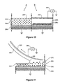
- Figure 10 comprises two sections, section A detailing the state of the marking or toner particles within a liquid toner film or layer prior to the imposition of an electric field through said layer and section B detailing the result of the imposition of an electric field through the liquid toner layer on the marking particles and the generation of a marking particle free carrier liquid layer.
- a process (not illustrated) is used to form a film of liquid developing agent 224 on the surface of a developing agent bearing member 226, wherein the liquid developing agent 224 is formed from marking particles 228 dispersed in a dielectric liquid 230.
- the liquid developing agent having a viscosity of up to 10,000 mPa.s., and a marking particle concentration of up to 60% by weight.
- Marking particles 228 are illustrated as possessing an inherently positive charge. It would be understood by those skilled in the art that marking particles possessing a negative charge could be utilised in the present invention.
- the spatial distribution of the marking particles 228 is relatively uniform within the toner 224.
- a bias electrode 232 is placed in uniform contact with the liquid developer layer 224.
- Power supply 234 imposes an electric field through the film of liquid toner 224 on the development agent bearing member 226, thus forming a potential difference through the toner layer, whereby the film of liquid developing agent splits into two spatially separated layers; one layer comprising of an increased concentration of marking particles 228b compacted close to the development agent bearing member 226, and a second layer of carrier fluid 230b positioned above the compacted toner layer, and substantially free from marking particles 228b.
- bias electrode 232 can take various forms.
- a roller connected to power supply 234 could be placed on the toner layer to generate the two spatially separated layers.
- a bias electrode could be connected to power supply 234, and in which the development bearing member 226 with the liquid developer layer is passed under the electrode and thereby generating the two spatially separated layers.
- the bias electrode 232 could comprise a blade or the like.
- a discharge device such as a corotron or scorotron could be used to form a potential difference through the liquid toner layer. That is, a substantially uniform charge is placed on the surface of the liquid toner film to thereby generate the two spatially separated layers.
- a developed toner image 300 is carried around on the surface of an intermediate transfer roller, belt or an imaging roller 310, passes under a carrier liquid displacement roller 350.
- the carrier liquid displacement roller 350 has a voltage V impressed upon it by voltage supply 380. This acts to push the marking particles 370 of the toner image down to the surface of intermediate transfer roller, belt or imaging roller 310 so that further liquid displacement occurs before the toner image is transferred to a substrate stage (not shown).
- Carrier liquid 330 trapped between the marking particles 370 of the developed image 300 is substantially removed.
- a layer, or possibly a further layer depending at which step in the process the carrier liquid displacement is occurring, of carrier liquid 335 is formed outside the toner layer as discussed in relation to Figure 10 .
- the toner carrier liquid displacement roller 350 also acts to remove this excess carrier liquid from the layer of carrier liquid 335, and leaving only a very small amount of carrier liquid 340.
- the excess liquid 360 is scraped off the roller 350 by a scraper (not shown) and can be recycled.
- each of the rollers may have a voltage impressed upon it as shown schematically in Figures 1 to 3 .
- the voltage on the supply roller 13 may be the same as the voltage on the pick-up roller 16 (V PR1 ), the metering roller 21 (V PR2 ) and the development member 31 (V DR ).
- the voltage V IR applied to the imaging roller 41 is equal to zero; which provides the current path during the formation of the latent electrostatic image on the surface of the imaging roller, toner development, and transfer from the surface of the imaging roller.
- the voltage on each of the first four rollers is in the range of +50 to 800 volts and the voltage on the surface of the imaging roller is a maximum of 1000 volts.
- a voltage (V TC1 ) is placed on carrier liquid displacement roller 33c in Figure 3
- a voltage (V TC2 ) is placed on carrier liquid displacement roller 35 in Figure 3 . Both these voltages should be higher than that applied to the roller upon which it bears to give an effect of driving toner particles towards the respective development and imaging rollers.
- V TR A voltage (V TR ) is placed onto the intermediate transfer roller 51 to attract the developed image to that roller and a voltage (V P ) is provided on the pressure roller 62 to assist with transfer of toner particles to the substrate 61.
- V CL A further voltage (V CL ) is placed onto the cleaner roller 81 to remove any final toner particles from the intermediate transfer roller before a new image is placed thereon.
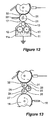
- Figure 12 is an alternative embodiment of the toner supply portion of the present invention.
- the schematic electrostatic printing process is generally as described in Figure 1 and the same reference numerals are used for corresponding items.
- a toner tank 11 has counter rotating gear wheels 12 which extend into toner 11a in the tank 11 and provide a supply of high viscosity toner to a supply roller 13.
- the supply roller extends out of the top of the toner tank 11 and is spaced apart from a metering roller 21 by a gap 17 which is in the range of from 50 to 400 ⁇ m. This produces a layer of toner on the metering roller of at least 50 ⁇ m.
- the toner supply stage may comprise other forms or methods of supplying, pumping or otherwise moving the toner from toner tank 11 to metering roller 21.
- the metering roller 21 has a pattern of recesses on its surface and a doctor blade 23 bearing against the metering roller 21 scrapes essentially all of the high viscosity toner off the metering roller 21 except that toner which is within the recesses in the pattern of recesses on the metering roller 21.
- the metering roller preferably has a trihelical pattern with a resolution of 200 lines per inch with a normal pattern depth of 30 ⁇ m.
- the metering roller 21 bears against a development member 31 with an interference fit 32 which is within the range of 50 to 2000 ⁇ m.
- the interference fit is made possible because although the surface of the metering roller 21 is relatively hard, the surface of the development member 31 is relatively soft and the metering roller 21 pushes into the development member 31.
- the interference fit provides a contact time during the rotation of each roller during which toner may be transferred from the metering roller 21 to the development member 31.
- the thickness of toner on the development member 31 after it has been transferred from the metering roller 21 is in the range of from 1 to 40 ⁇ m.
- Figure 13 is an alternative embodiment of the toner supply portion of the present invention.
- the schematic electrostatic printing process is generally as described in Figure 1 and the same reference numerals are used for corresponding items.
- the toner supply stage is as discussed in relation to Figure 1 up to the pick-up roller 16.
- the pick-up roller 16 has a doctor blade 18 bearing against it to provide an even thin layer of high viscosity toner onto the pick-up roller 16.
- the pick-up roller 16 in this embodiment can be in "kiss” contact or with an interference fit against a multi roller feed train of at least three or more smooth rollers.
- the pick-up roller 16 is in "kiss” contact with the first smooth roller 24.
- Each of the smooth rollers 24, 25 and 26 are in "kiss” contact or with an interference fit with each other.
- the interference fit between the three smooth rollers can be up to 1,000 ⁇ m.
- the degree of interference will determine the thickness of the toner layer that is presented to the development member 31.
- the feed rollers 24, 25 and 26 may comprise elastomer rollers coated with polyurethane or NBR or other suitable material.
- the electrical resistivity of the coating may be in the region of 10 4 to 10 8 ohm centimetres.
- the final smooth roller 26 bears against a development member 31 with an interference fit 32 which is up to 1000 ⁇ m.
- the interference fit is made possible because although the surface of the final smooth roller 26 is relatively hard, the surface of the development member 31 is relatively soft and the final smooth roller 26 pushes into the development member 31.
- the interference fit provides a contact time during the rotation of each roller during which toner maybe transferred from the final smooth roller 26 to the development member 31.
- the thickness of toner on the development member 31 after it has been transferred from the final smooth roller 26 is in the range of from 1 to 40 ⁇ m.
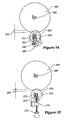
- FIG 14 shows detail of a mechanism for setting the interference fit between the metering roller and the development member according to the present invention.
- a metering roller 250 rotates on a shaft 252 which is carried in a bearing block 254 which travels in a slot 256 in a chassis of the printing machine.
- a cam 258 rotating on a shaft 260 engages the bearing block 254 and thereby pushes the metering roller into an interference fit 262 into the development member 264 which rotates on shaft 266.
- the interference fit can be set by rotation of the cam 258.
- FIG. 15 shows detail of an alternative mechanism for setting the interference fit between the metering roller and the development member according to the present invention.
- a metering roller 270 rotates on a shaft 272 which is carried in a bearing block 274 which travels in a slot 276 in a chassis of the printing machine.
- a set screw 278 extending through a threaded block 279 engages the bearing block 274 and thereby pushes the metering roller into an interference fit 282 into the development member 284 which rotates on shaft 286.
- the mechanisms shown in Figures 14 and 15 can also be used to set the interference fit between the development member and the imaging member and between the imaging member and the intermediate transfer roller.
- the voltages applied to the various rollers are as follows: V FR +50 to +800 volts V PR1 +50 to +800 volts V PR2 +50 to +800 volts V DR +50 to + 800 volts V IR 0 volts V TR -50 to -2000 volts V P -500 to -2500 V TC1 (development stage) +50 to +1500 volts V TC2 (imaging stage) +50 to+600 volts V TC3 (intermediate stage) +50 to+1000 volts V CL -50 to -2500 volts
- rollers can be of a selected size for more efficient operation.
- the development member should have a preferred diameter of 0.1 to 1.0 units, more preferably 0.3 units;
- the metering roller should have a preferred diameter of 0.1 to 0.5 units, more preferably 0.2 units;
- the pick-up roller should have a preferred diameter of 0.1 to 0.5 units, more preferably 0.4 units;
- the supply roller should have a preferred diameter of 0.1 to 0.3 units, more preferably 0.1 units.
- roller diameters of a selected size are as follows.
- Alpha-Si for example, has the highest discharge rate and therefore the photoconductor diameter could be reduced to still satisfy the discharge time requirements.
- Alpha-Si is a preferred embodiment of the present invention for the photoconductor. Knowing the photoconductor discharge rate (less than 20 ms), it can be determined that the minimum circumferential distance between the exposure location and the development nip at a surface rotation speed of 1.5 ms -1 would be approximately 30 mm. In selecting the imaging roller diameter, for one of the preferred embodiments of the present invention, consideration was given to the diameter values that are widely available commercially.
- Toner particles even in high viscosity toning applications with virtually zero development gap, would need some time to deposit fully onto an imaging roller. It is estimated that this minimum time is 1 - 3 ms, and is dependent on toner mobility, development bias, photoconductor residual charge, toner layer thickness and development member properties.
- the development nip width should be in excess of 3mm. For a 242 mm imaging roller diameter and a development member of approximately 40 Shore A hardness, a development member diameter of approximately 80 mm is needed to attain the required development nip width.
- the various rollers in the toner feed train, the supply roller, the pick-up roller and the metering roller can all have small diameters, commensurate with their function so that as small a toner feed system as possible can be provided.
- other rollers, such as the carrier liquid displacement and cleaning rollers can be of a diameter commensurate with their function, as would be understood by those practised in the art.
- the preferred diameter of the various rollers is as follows: Roller Ratio Preferred Ratio Preferred Diameter (mm) Image Carrying 1.0 1.0 200 Development 0.1-1.0 0.3 60 Metering 0.1-0.5 0.2 40 Pick-up 0.1-0.5 0.4 80 Toner Supply 0.1-0.3 0.1 20
- the development member may have the following preferable characteristics: Development member Range Preferred Roughness Rz ⁇ 2 ⁇ m Rz ⁇ 2 ⁇ m Hardness of coating 40 - 60° Shore A 50° Shore A Surface energy 30 - 40 mN/m 35 mN/m Electrical resistivity 1x10 4 -1 ⁇ 10 8 ⁇ cm 1x10 6 ⁇ cm
- the intermediate transfer member may be a roller or belt, and may have the following preferable characteristics: Intermediate Member Range Preferred Roughness Rz ⁇ 2 ⁇ m Rz ⁇ 2 ⁇ m Hardness of coating 40 - 70° Shore A 60° Shore A Surface energy 20 - 40 mN/m 30 mN/m Electrical resistivity 1x10 4 -1 ⁇ 10 8 ⁇ cm 1x10 7 ⁇ cm
- rollers may have additional over coatings.
- the preferred materials to be used for overcoating are polyurethane and fluorinated rubbers (silicone rubbers could be used also).
- a high viscosity, high concentration toner suitable for use with the present invention may have a formulation as follows: Colour Pigment 2 - 30% Fixing Resin 8 - 30% Charge Control Agent 0 - 5% Dispersing Agent 0 - 10% Carrier liquid 40-90% Solid Content 1-60%
- the carrier liquid may comprise any suitable liquids as is known in the art, and may include silicone fluids, hydrocarbon liquids and vegetable oils, or any combinations thereof.
- the present invention solves the herein described prior art and other problems, thereby advancing the state of the useful arts, by providing a method of developing an electrostatic latent image with highly viscous, highly concentrated liquid toners at high speed.
- Viscosities were measured using a HAAKE RheoStress RS600.
Landscapes
- Physics & Mathematics (AREA)
- General Physics & Mathematics (AREA)
- Wet Developing In Electrophotography (AREA)
- Electrostatic Charge, Transfer And Separation In Electrography (AREA)
- Fixing For Electrophotography (AREA)
- Liquid Developers In Electrophotography (AREA)
- Cleaning In Electrography (AREA)
Applications Claiming Priority (2)
| Application Number | Priority Date | Filing Date | Title |
|---|---|---|---|
| AU2005904960A AU2005904960A0 (en) | 2005-09-09 | High speed electrographic printing | |
| EP06774936.6A EP1929377A4 (fr) | 2005-09-09 | 2006-09-07 | Impression electrographique grande vitesse |
Related Parent Applications (1)
| Application Number | Title | Priority Date | Filing Date |
|---|---|---|---|
| EP06774936.6A Division EP1929377A4 (fr) | 2005-09-09 | 2006-09-07 | Impression electrographique grande vitesse |
Publications (1)
| Publication Number | Publication Date |
|---|---|
| EP2866097A1 true EP2866097A1 (fr) | 2015-04-29 |
Family
ID=37835309
Family Applications (2)
| Application Number | Title | Priority Date | Filing Date |
|---|---|---|---|
| EP20140191895 Withdrawn EP2866097A1 (fr) | 2005-09-09 | 2006-09-07 | Impression électrographique à grande vitesse |
| EP06774936.6A Withdrawn EP1929377A4 (fr) | 2005-09-09 | 2006-09-07 | Impression electrographique grande vitesse |
Family Applications After (1)
| Application Number | Title | Priority Date | Filing Date |
|---|---|---|---|
| EP06774936.6A Withdrawn EP1929377A4 (fr) | 2005-09-09 | 2006-09-07 | Impression electrographique grande vitesse |
Country Status (5)
| Country | Link |
|---|---|
| US (2) | US7995953B2 (fr) |
| EP (2) | EP2866097A1 (fr) |
| JP (1) | JP5377964B2 (fr) |
| KR (1) | KR101277716B1 (fr) |
| WO (1) | WO2007028205A1 (fr) |
Families Citing this family (28)
| Publication number | Priority date | Publication date | Assignee | Title |
|---|---|---|---|---|
| JP5301562B2 (ja) | 2007-12-21 | 2013-09-25 | アペックス・ヨーロッパ・ビー.ブイ. | アニロックスロールを使用して被印刷物に印刷するための方法、印刷方法のためのアニロックスロール及び印刷装置 |
| JP2011064960A (ja) * | 2009-09-17 | 2011-03-31 | Canon Inc | トナー画像定着方法 |
| DE102009056427B4 (de) * | 2009-12-01 | 2011-09-01 | OCé PRINTING SYSTEMS GMBH | Verfahren zum Bedrucken eines endlosen Bedruckstoffs mit einem elektrophoretischen Druckgerät |
| CN102650844A (zh) * | 2011-02-24 | 2012-08-29 | 精工爱普生株式会社 | 显影装置、图像形成装置以及回收装置 |
| JP2012194426A (ja) * | 2011-03-17 | 2012-10-11 | Seiko Epson Corp | 現像装置および画像形成装置 |
| KR101144610B1 (ko) * | 2011-08-02 | 2012-05-11 | 한국기계연구원 | 투명 전극의 전도성 메쉬 매설 방법 |
| JP2013257501A (ja) * | 2012-06-14 | 2013-12-26 | Konica Minolta Inc | 液体現像装置および湿式画像形成装置 |
| EP2685320A1 (fr) | 2012-07-10 | 2014-01-15 | Xeikon IP BV | Appareil d'impression numérique et procédé d'impression numérique |
| EP2713210B1 (fr) | 2012-09-28 | 2017-06-14 | Xeikon Manufacturing NV | Dispersion de révélateur liquide pour procédé d'impression numérique |
| EP2765460A1 (fr) | 2013-02-07 | 2014-08-13 | Xeikon IP BV | Unité d'application d'images destinée à être utilisée avec du toner liquide et unité d'impression numérique la comprenant |
| NL2010581C2 (en) | 2013-04-05 | 2014-10-08 | Xeikon Ip B V | Method and system for reduction of caking. |
| NL2010574C2 (en) * | 2013-04-05 | 2014-10-07 | Xeikon Ip B V | SYSTEM FOR APPLYING LIQUID TONER TO AN IMAGE FORMING MEMBER IN A DIGITAL PRINTER. |
| NL2011064C2 (en) | 2013-06-28 | 2015-01-05 | Xeikon Ip B V | Digital printing apparatus and digital printing process. |
| JP6291757B2 (ja) * | 2013-09-17 | 2018-03-14 | コニカミノルタ株式会社 | 湿式現像装置および湿式画像形成装置 |
| JP2015179196A (ja) * | 2014-03-19 | 2015-10-08 | 富士ゼロックス株式会社 | 供給部材及び画像形成装置 |
| JP6070643B2 (ja) * | 2014-06-20 | 2017-02-01 | コニカミノルタ株式会社 | 湿式現像装置および湿式画像形成装置 |
| NL2013779B1 (en) | 2014-11-12 | 2016-10-07 | Xeikon Ip Bv | Stirring apparatus and method for stirring a liquid. |
| NL2014470B1 (en) | 2015-03-17 | 2017-01-13 | Xeikon Ip Bv | Apparatus and method for determining a measure for the solid content of a liquid toner, and printing system including such an apparatus. |
| JP2016177000A (ja) * | 2015-03-18 | 2016-10-06 | 富士ゼロックス株式会社 | 現像装置及び画像形成装置 |
| NL2016339B1 (en) | 2016-03-01 | 2017-09-11 | Xeikon Mfg Nv | Digital printing apparatus and method using liquid toner. |
| NL2016657B1 (en) | 2016-04-22 | 2017-11-15 | Xeikon Mfg Nv | Digital printing apparatus and digital printing process |
| WO2018177539A1 (fr) | 2017-03-31 | 2018-10-04 | Hp Indigo B.V. | Dispositifs de transfert d'impression électrophotographique liquide |
| NL2020081B1 (en) | 2017-12-13 | 2019-06-21 | Xeikon Mfg Nv | Digital printing apparatus and method |
| US11119437B2 (en) | 2018-08-07 | 2021-09-14 | Hewlett-Packard Development Company, L.P. | Determining cleaning fluid thickness |
| JP2020042090A (ja) | 2018-09-07 | 2020-03-19 | エイチピー プリンティング コリア カンパニー リミテッドHP Printing Korea Co., Ltd. | 画像形成システム |
| JP2020060731A (ja) | 2018-10-12 | 2020-04-16 | エイチピー プリンティング コリア カンパニー リミテッドHP Printing Korea Co., Ltd. | 潤滑剤塗布装置 |
| CN110624760A (zh) * | 2019-09-20 | 2019-12-31 | 无锡市天牛智能装备有限公司 | 多辊双面涂布机 |
| KR102152689B1 (ko) * | 2019-11-13 | 2020-09-07 | 박주용 | 그라비아 인쇄장치 |
Citations (7)
| Publication number | Priority date | Publication date | Assignee | Title |
|---|---|---|---|---|
| US5612162A (en) | 1993-01-22 | 1997-03-18 | Research Laboratories Of Australia Pty Ltd. | Liquid developer for electrostatography |
| US6137976A (en) | 1994-02-08 | 2000-10-24 | Research Laboratories Of Australia Pty Ltd. | Image formation apparatus using a liquid developing agent |
| US6167225A (en) | 1994-01-10 | 2000-12-26 | Research Laboratories Of Australia Pty Ltd | Liquid developing method of electrostatic latent image and liquid developing apparatus |
| US6287741B1 (en) | 1999-09-03 | 2001-09-11 | Research Laboratories Of Australia Pty Ltd | Liquid toner composition |
| US20010026711A1 (en) * | 2000-03-28 | 2001-10-04 | Weizhong Zhao | Method and apparatus for toner cake delivery |
| US6613209B2 (en) | 2000-01-28 | 2003-09-02 | Research Laboratories Of Australia Pty Ltd. | Toner characterization cell |
| US20040005407A1 (en) * | 2001-11-20 | 2004-01-08 | Noriyasu Takeuchi | Developing liquid coating device, developing device including the same and image forming apparatus including the developing device |
Family Cites Families (35)
| Publication number | Priority date | Publication date | Assignee | Title |
|---|---|---|---|---|
| JPS5520578B2 (fr) * | 1973-02-21 | 1980-06-03 | ||
| GB1441655A (en) * | 1973-06-25 | 1976-07-07 | Xerox Corp | Electrostatographic reproduction machines |
| US4395113A (en) * | 1981-10-29 | 1983-07-26 | Nashua Corporation | Methods and apparatus for cleaning photoconductive members |
| JPH07239615A (ja) * | 1994-01-10 | 1995-09-12 | Nippon Steel Corp | 静電潜像の液体現像方法及び液体現像装置 |
| JP2004139114A (ja) * | 1994-01-10 | 2004-05-13 | Research Lab Of Australia Pty Ltd | 静電潜像の液体現像装置 |
| WO1995018993A1 (fr) * | 1994-01-10 | 1995-07-13 | Nippon Steel Corporation | Procede utilisant un revelateur liquide pour developper une image electrostatique latente et appareil de developpement a revelateur liquide |
| JPH08160735A (ja) * | 1994-12-09 | 1996-06-21 | Canon Inc | 画像形成装置 |
| JPH08297417A (ja) * | 1995-04-27 | 1996-11-12 | Minolta Co Ltd | 液体現像剤搬送装置 |
| JP4263773B2 (ja) * | 1995-05-29 | 2009-05-13 | リサーチ ラボラトリーズ オブ オーストラリアプロプライエタリイ リミテッド | 画像形成装置 |
| JP3766960B2 (ja) * | 1995-05-29 | 2006-04-19 | リサーチ ラボラトリーズ オブ オーストラリアプロプライエタリイ リミテッド | 静電潜像の液体現像装置及び液体現像方法 |
| JPH09185230A (ja) * | 1995-12-27 | 1997-07-15 | Sony Corp | 液体現像剤を用いた現像装置及びこれを備えた画像形成装置 |
| JPH09319228A (ja) * | 1996-05-29 | 1997-12-12 | Fuji Xerox Co Ltd | 液体現像装置 |
| JPH10254257A (ja) * | 1997-01-08 | 1998-09-25 | Toray Ind Inc | 画像形成装置および画像形成方法 |
| US5987282A (en) * | 1997-04-18 | 1999-11-16 | Ricoh Company, Ltd. | Image forming apparatus with a developing device using a developing liquid |
| WO1999010779A1 (fr) * | 1997-08-27 | 1999-03-04 | Pfu Limited | Dispositif electrophotographique a liquide |
| JPH11153906A (ja) * | 1997-09-19 | 1999-06-08 | Ricoh Co Ltd | 液体現像装置 |
| JPH11223997A (ja) * | 1997-11-03 | 1999-08-17 | Xerox Corp | 液状現像剤を用いる撮像装置および撮像方法 |
| JPH11194622A (ja) * | 1998-01-07 | 1999-07-21 | Matsushita Electric Ind Co Ltd | 現像装置 |
| JPH11265122A (ja) * | 1998-01-08 | 1999-09-28 | Ricoh Co Ltd | 画像形成装置 |
| US6163669A (en) * | 1998-05-29 | 2000-12-19 | Ricoh Company, Ltd. | Image forming apparatus |
| US6236825B1 (en) * | 1998-11-26 | 2001-05-22 | Ricoh Company, Ltd. | Image forming apparatus including liquid-type developing device |
| JP3822992B2 (ja) * | 1999-01-26 | 2006-09-20 | 株式会社リコー | 湿式画像形成装置 |
| ATE407159T1 (de) | 2000-06-30 | 2008-09-15 | Kraton Polymers Res Bv | Blockcopolymere mit polystyren und mit niedrigem vinylanteil polydien harte blöcken |
| JP2002202663A (ja) * | 2000-12-28 | 2002-07-19 | Ricoh Co Ltd | 現像装置及び画像形成装置 |
| US6640073B2 (en) * | 2001-01-23 | 2003-10-28 | Ricoh Company, Ltd. | Liquid image formation apparatus and liquid developing device |
| US6735408B2 (en) * | 2001-03-21 | 2004-05-11 | Ricoh Company, Ltd. | Image forming apparatus with adjustable removal and developing nips |
| WO2002093269A1 (fr) * | 2001-05-11 | 2002-11-21 | Pfu Limited | Systeme de regulation de recyclage de toner pour appareil electrophotographique utilisant un bain revelateur liquide visqueux |
| US6842599B2 (en) * | 2001-08-30 | 2005-01-11 | Pfu Limited | Liquid developing system developing device |
| KR100421024B1 (ko) * | 2002-02-07 | 2004-03-04 | 삼성전자주식회사 | 미터링 롤러를 구비하는 습식 칼라 화상형성장치의 현상장치 |
| JP2003255715A (ja) * | 2002-02-28 | 2003-09-10 | Pfu Ltd | 液体トナーを用いる電子写真装置 |
| KR100462616B1 (ko) * | 2002-07-12 | 2004-12-20 | 삼성전자주식회사 | 습식 화상형성시스템 및 그를 이용한 화상형성방법 |
| JP2005049496A (ja) * | 2003-07-31 | 2005-02-24 | Kyocera Mita Corp | 画像形成装置 |
| JP2005070572A (ja) * | 2003-08-27 | 2005-03-17 | Kyocera Mita Corp | 現像剤収容器,現像装置 |
| JP2006047558A (ja) * | 2004-08-03 | 2006-02-16 | Canon Inc | 現像ローラおよびその製造方法ならびにこれを用いた現像装置および電子写真プロセスカートリッジ |
| WO2006047558A2 (fr) | 2004-10-26 | 2006-05-04 | The General Hospital Corporation | Methodes de detection d'une fibrillation atriale et de troubles lies |
-
2006
- 2006-09-07 WO PCT/AU2006/001307 patent/WO2007028205A1/fr active Application Filing
- 2006-09-07 JP JP2008529421A patent/JP5377964B2/ja not_active Expired - Fee Related
- 2006-09-07 KR KR1020087008502A patent/KR101277716B1/ko not_active IP Right Cessation
- 2006-09-07 EP EP20140191895 patent/EP2866097A1/fr not_active Withdrawn
- 2006-09-07 EP EP06774936.6A patent/EP1929377A4/fr not_active Withdrawn
- 2006-09-07 US US11/991,659 patent/US7995953B2/en not_active Expired - Fee Related
-
2011
- 2011-07-01 US US13/135,341 patent/US20120063812A1/en not_active Abandoned
Patent Citations (7)
| Publication number | Priority date | Publication date | Assignee | Title |
|---|---|---|---|---|
| US5612162A (en) | 1993-01-22 | 1997-03-18 | Research Laboratories Of Australia Pty Ltd. | Liquid developer for electrostatography |
| US6167225A (en) | 1994-01-10 | 2000-12-26 | Research Laboratories Of Australia Pty Ltd | Liquid developing method of electrostatic latent image and liquid developing apparatus |
| US6137976A (en) | 1994-02-08 | 2000-10-24 | Research Laboratories Of Australia Pty Ltd. | Image formation apparatus using a liquid developing agent |
| US6287741B1 (en) | 1999-09-03 | 2001-09-11 | Research Laboratories Of Australia Pty Ltd | Liquid toner composition |
| US6613209B2 (en) | 2000-01-28 | 2003-09-02 | Research Laboratories Of Australia Pty Ltd. | Toner characterization cell |
| US20010026711A1 (en) * | 2000-03-28 | 2001-10-04 | Weizhong Zhao | Method and apparatus for toner cake delivery |
| US20040005407A1 (en) * | 2001-11-20 | 2004-01-08 | Noriyasu Takeuchi | Developing liquid coating device, developing device including the same and image forming apparatus including the developing device |
Also Published As
| Publication number | Publication date |
|---|---|
| JP5377964B2 (ja) | 2013-12-25 |
| US7995953B2 (en) | 2011-08-09 |
| KR101277716B1 (ko) | 2013-06-24 |
| WO2007028205A1 (fr) | 2007-03-15 |
| EP1929377A4 (fr) | 2014-04-30 |
| JP2009507258A (ja) | 2009-02-19 |
| US20120063812A1 (en) | 2012-03-15 |
| EP1929377A1 (fr) | 2008-06-11 |
| KR20080044342A (ko) | 2008-05-20 |
| US20090052948A1 (en) | 2009-02-26 |
Similar Documents
| Publication | Publication Date | Title |
|---|---|---|
| EP2866097A1 (fr) | Impression électrographique à grande vitesse | |
| EP0764891B1 (fr) | Cartouche de révélateur à toner liquide | |
| EP0678202B1 (fr) | Appareil de revelation d'images latentes | |
| US7522865B2 (en) | Toner development unit | |
| US4482241A (en) | Device and method for stripping developer from a photoconductive surface | |
| JP3214120B2 (ja) | 帯電装置及び画像形成装置 | |
| US5314774A (en) | Method and apparatus for developing color images using dry toners and an intermediate transfer member | |
| IL191873A (en) | Charging member for an image forming apparatus | |
| JPS62242977A (ja) | 静電荷像の電気泳動現像 | |
| US6311034B1 (en) | Wet type electrophotography apparatus to evenly apply developing solution on a developing roller | |
| US10901344B2 (en) | Binary ink developer (BID) assembly for liquid electrophotography (LEP) printing device | |
| US6701111B2 (en) | Liquid image developing system | |
| US8208825B2 (en) | Electrostatographic printing machine | |
| KR100382020B1 (ko) | 화상 형성 방법 | |
| US20080240794A1 (en) | Printing machine incorporating plastic metering roller | |
| EP1117014B1 (fr) | Appareil révélateur d'images latentes | |
| JP2002040799A (ja) | 現像ロール及びそれを有する現像装置 | |
| US10222719B2 (en) | Electro-photographic printing | |
| JP3482780B2 (ja) | 帯電部材及び帯電装置 | |
| JP2001034073A (ja) | 液体トナー現像方式の電子写真装置 | |
| JP2001337531A (ja) | 液体現像電子写真装置 | |
| JP2000122375A (ja) | 帯電装置及びこれを用いた画像形成装置 | |
| JPH06314055A (ja) | 画像形成装置 |
Legal Events
| Date | Code | Title | Description |
|---|---|---|---|
| PUAI | Public reference made under article 153(3) epc to a published international application that has entered the european phase |
Free format text: ORIGINAL CODE: 0009012 |
|
| 17P | Request for examination filed |
Effective date: 20141105 |
|
| AC | Divisional application: reference to earlier application |
Ref document number: 1929377 Country of ref document: EP Kind code of ref document: P |
|
| AK | Designated contracting states |
Kind code of ref document: A1 Designated state(s): AT BE BG CH CY CZ DE DK EE ES FI FR GB GR HU IE IS IT LI LT LU LV MC NL PL PT RO SE SI SK TR |
|
| R17P | Request for examination filed (corrected) |
Effective date: 20150921 |
|
| RBV | Designated contracting states (corrected) |
Designated state(s): AT BE BG CH CY CZ DE DK EE ES FI FR GB GR HU IE IS IT LI LT LU LV MC NL PL PT RO SE SI SK TR |
|
| STAA | Information on the status of an ep patent application or granted ep patent |
Free format text: STATUS: REQUEST FOR EXAMINATION WAS MADE |
|
| STAA | Information on the status of an ep patent application or granted ep patent |
Free format text: STATUS: THE APPLICATION IS DEEMED TO BE WITHDRAWN |
|
| 18D | Application deemed to be withdrawn |
Effective date: 20190402 |