EP2856878B1 - Food dough spreading device and food dough spreading method - Google Patents
Food dough spreading device and food dough spreading method Download PDFInfo
- Publication number
- EP2856878B1 EP2856878B1 EP13797581.9A EP13797581A EP2856878B1 EP 2856878 B1 EP2856878 B1 EP 2856878B1 EP 13797581 A EP13797581 A EP 13797581A EP 2856878 B1 EP2856878 B1 EP 2856878B1
- Authority
- EP
- European Patent Office
- Prior art keywords
- food dough
- spreading
- rollers
- vibration applying
- applying members
- Prior art date
- Legal status (The legal status is an assumption and is not a legal conclusion. Google has not performed a legal analysis and makes no representation as to the accuracy of the status listed.)
- Active
Links
Images


Classifications
-
- A—HUMAN NECESSITIES
- A21—BAKING; EDIBLE DOUGHS
- A21C—MACHINES OR EQUIPMENT FOR MAKING OR PROCESSING DOUGHS; HANDLING BAKED ARTICLES MADE FROM DOUGH
- A21C3/00—Machines or apparatus for shaping batches of dough before subdivision
- A21C3/02—Dough-sheeters; Rolling-machines; Rolling-pins
-
- A—HUMAN NECESSITIES
- A21—BAKING; EDIBLE DOUGHS
- A21C—MACHINES OR EQUIPMENT FOR MAKING OR PROCESSING DOUGHS; HANDLING BAKED ARTICLES MADE FROM DOUGH
- A21C11/00—Other machines for forming the dough into its final shape before cooking or baking
- A21C11/10—Other machines for forming the dough into its final shape before cooking or baking combined with cutting apparatus
-
- A—HUMAN NECESSITIES
- A21—BAKING; EDIBLE DOUGHS
- A21C—MACHINES OR EQUIPMENT FOR MAKING OR PROCESSING DOUGHS; HANDLING BAKED ARTICLES MADE FROM DOUGH
- A21C3/00—Machines or apparatus for shaping batches of dough before subdivision
- A21C3/02—Dough-sheeters; Rolling-machines; Rolling-pins
- A21C3/021—Rolling-pins; Hand-operated spreading or rolling devices
-
- A—HUMAN NECESSITIES
- A21—BAKING; EDIBLE DOUGHS
- A21C—MACHINES OR EQUIPMENT FOR MAKING OR PROCESSING DOUGHS; HANDLING BAKED ARTICLES MADE FROM DOUGH
- A21C3/00—Machines or apparatus for shaping batches of dough before subdivision
- A21C3/04—Dough-extruding machines ; Hoppers with moving elements, e.g. rollers or belts as wall elements for drawing the dough
-
- A—HUMAN NECESSITIES
- A21—BAKING; EDIBLE DOUGHS
- A21C—MACHINES OR EQUIPMENT FOR MAKING OR PROCESSING DOUGHS; HANDLING BAKED ARTICLES MADE FROM DOUGH
- A21C9/00—Other apparatus for handling dough or dough pieces
- A21C9/08—Depositing, arranging and conveying apparatus for handling pieces, e.g. sheets of dough
- A21C9/085—Separating, spacing, orienting or aligning discrete dough pieces, e.g. after passing a cutting device
Definitions
- the present invention relates to a method and a device for spreading arbitrary food dough, for example, bread dough, and more particularly relates to a food dough spreading device and a food dough spreading method that can adjust a width dimension of spread food dough to a desired dimension, and can suppress internal stress at both side edges in a width direction.
- a spreading unit having a plurality of spreading rollers arranged in a V-shape is provided below a hopper that stores therein the food dough, and the food dough is supplied from the hopper to between the spreading rollers so that the food dough is gradually spread to be made thinner. It has been proposed to adjust a pair of width regulating members arranged between the spreading rollers in a direction approaching and separating from each other, in order to adjust the width dimension of the food dough to be spread by the spreading rollers (see, for example, Patent Literature 1).
- both sides in a width direction of food dough to be spread gradually by a plurality of spreading rollers are regulated by a pair of width regulating members. Because the width regulating members are position-adjustable, the width dimension of the food dough to be spread can be adjusted. However, in the above configuration, the width regulating member can be only position-adjustable, and thus the both side edges in the width direction of food dough to be gradually spread to be made thinner by the spreading rollers tend to be pressed against the width regulating member and to adhere thereto. Therefore, there is a problem that the internal stress tends to be applied to the both side edges of the food dough to be spread.
- an object of the present invention is to provide a food dough spreading device and a food dough spreading method that can avoid internal stress remaining in food dough by repeating compression and release of the food dough and repeating application and release of the internal stress.
- the width dimension of the food dough to be spread can be adjusted. Because the vibration applying members are reciprocatively vibrated in the longitudinal direction of the spreading rollers, the both side edges in the width direction of the food dough are repeatedly compressed and released. Therefore, application and release of the internal stress are repeated, and the internal stress does not remain in the food dough. Furthermore, by vibrating the vibration applying members, a relative movement (a flow) of the food dough with respect to the vibration applying member is smoothly performed.
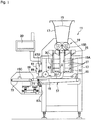
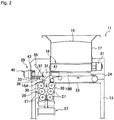
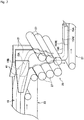
- a food dough spreading device 11 As shown conceptually and schematically in FIGS. 1 and 2 , a food dough spreading device 11 according to the embodiment of the present invention includes a mount 13, and a box-shaped hopper 17 that stores therein arbitrary food dough 15, for example, bread dough is provided above the mount 13. At a position corresponding to an opening position at the bottom of the hopper 17, a cutting device 19 that cuts the food dough 15 supplied downward from the hopper 17 into a predetermined length is provided.
- the food dough spreading device 11 is provided with a control device 20 formed of a computer in order to control the entire operation of the device.
- the cutting device 19 cuts the food dough 15 into a length corresponding to the cutting device 19 by rotationally driving a motor 21 intermittently under control of the control device 20.
- Configurations of the hopper 17 and the cutting device 19 have been already known, and thus detailed explanations of the hopper 17 and the cutting device 19 will be omitted.
- a belt conveyor 23 as a delivery unit that delivers (transfers) the long food dough 15, which has been cut into the predetermined length by the cutting device and has been dropped, in a longitudinal direction (leftward in FIG. 2 ) is provided below the cutting device 19.
- the belt conveyor 23 is driven to travel by a motor (not shown), and the transportation velocity of delivering the food dough 15 in the longitudinal direction can be controlled under control of the control device 20.
- the configuration of the belt conveyor 23 has been well known, and thus detailed explanations of the belt conveyor 23 will be omitted.
- the food dough spreading device is provided with a rear-end detection sensor 24 that detects that a rear end of the food dough 15 is delivered to a predetermined position, when the food dough 15 on the belt conveyor 23 is delivered in the longitudinal direction and the rear end thereof is delivered to the predetermined position.
- the motor 21 is rotationally driven under control of the control device 20, and the next food dough 15 is cut and dropped onto the belt conveyor 23.
- a front end side of following food dough 15B overlaps on the rear end side of preceding food dough 15A.
- a configuration of cutting the following food dough 15B sequentially by the cutting device 19 such a configuration is possible that the cutting device 19 is operated to cut the food dough 15 every time a set time set beforehand to a timer has passed.
- a spreading unit 25 is provided corresponding to a position of a downstream end of the belt conveyor 23. That is, the spreading unit 25 is provided at a position to receive the food dough 15 delivered in the horizontal direction (leftward in FIG. 2 ) by the belt conveyor 23 and moved downward from the downstream end of the belt conveyor 23.
- the spreading unit 25 is provided, as shown in FIG. 2 , on the mount 13 at a position lower than the belt conveyor 23, and has such a configuration that a plurality of spreading rollers 27 are arranged in a V-shape so as to press an overlapping portion of the rear end side of the preceding food dough 15A and the front end side of the following food dough 15B from an overlapping direction. More specifically, the respective spreading rollers 27 are provided rotatably on a roller mount 30 fixed to the mount 13 in a V-shape. The respective spreading rollers 27 have a configuration in which the respective spreading rollers 27 coordinate with each other via an appropriate power transmission mechanism (not shown) such as a chain or a gear, and rotate faster toward the downstream side.
- an appropriate power transmission mechanism not shown
- the spreading unit that spreads food dough 15 by arranging the plurality of spreading rollers 27 in a V-shape has been already known.
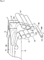
- the spreading unit 25 according to the present embodiment includes a vibration applying unit 29 (see FIGS. 3 ) that applies vibration in a width direction to both side edges in the width direction (a horizontal direction in FIG. 1 , a longitudinal direction of the spreading roller 27) of the food dough 15 spread by the spreading rollers 27.
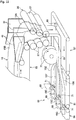
- a pair of vibration applying members 31 provided in the vibration applying unit 29 are provided, as shown in FIGS. 1 and 3 , between the spreading rollers 27 arranged in a V-shape.
- the vibration applying members 31 are provided so that an opposite distance becomes narrower as moving downward, and the lower side of the vibration applying members 31 gradually becomes thicker. Because the vibration applying members 31 are provided movably in the direction approaching and separating from each other, the width of the food dough 15 can be regulated.
- a base plate 33 which is long in the longitudinal direction of the spreading roller 27 is integrally provided on the mount 13.
- a pair of sliders 37 are movably provided in a guide member 35 provided on the base plate 33.
- Coupling members 39 integrally coupled with the vibration applying members 31 are respectively fixed to the pair of sliders 37.
- Guide members 41 facing an upper side of the belt conveyor 23, with an upstream side thereof being widened gradually, are integrally provided on an upper part of the pair of vibration applying members 31.
- a motor bracket 43 is integrally provided in a upright manner on one side of the base plate 33, in order to move the pair of vibration applying members 31 so as to approach or be separated from each other in the longitudinal direction of the spreading rollers 27.
- the motor bracket 43 is provided with a rotation drive device 45 such as a servo motor, and a drive pulley 49 such as a toothed pulley is provided on a rotation shaft 47 of the rotation drive device 45.
- a driven pulley 51 is rotatably provided at a position away from the drive pulley 49, and an endless member 53 such as a toothed belt is wound around the driven pulley 51 and the drive pulley 49.
- One of the coupling members 39 is coupled with an upper side of the endless member 53 and the other of the coupling members 39 is coupled with a lower side of the endless member 53.
- the pair of vibration applying members 31 can be moved in the direction approaching and separating from each other by setting the closed distance D1 and the stroke length ST of the pair of vibration applying members (the width regulating members) 31 in the control device 20 and positively rotating or negatively rotating the rotation drive device 45 under control of the control device 20.
- a width dimension of the food dough 15, which is subjected to a spreading action in the spreading unit 25 can be regulated to a desired dimension.
- the vibration applying members 31 can freely regulate the width dimension of the food dough 15 to be spread, thereby constituting a certain type of vibration applying member.
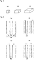
- the food dough in which cut pieces 15C of the food dough 15 have a square surface having the same thickness but having different lengths of vertical and horizontal sides from each other, as viewed in a planar view, can be formed as shown in FIGS. 8(A), 8(B), and 8(C) .
- the vibration applying members 31 can be reciprocatively vibrated in the width direction (in the longitudinal direction of the spreading rollers 27) at a position where the positioning has been performed, by repeating positive and negative rotation of the rotation drive device 45 within a desired rotation range. Accordingly, vibration can be applied to the both side edges in the width direction of the food dough 15 which is being spread by the spreading rollers 27. Therefore, adhesion of the food dough 15 to the vibration applying members 31 can be prevented, thereby enabling to move the food dough 15 smoothly.
- the food dough 15 surrounded by the pair of vibration applying members 31 and the spreading rollers 27 is alternately moved in the delivery direction (longitudinal direction in FIGS. 1 and 2 ) and the width direction by reciprocatively vibrating the vibration applying members 31 in the width direction, thereby enabling to improve spreading efficiency of the food dough 15 by the spreading rollers 27.
- vibration applying members 31 to apply vibration from both sides in the width direction, vibration can be applied to the entire food dough 15 in a portion subjected to the spreading action. Therefore, vibration can be applied to the entire portion of the food dough 15 subjected to the spreading action to be able to perform degassing.
- degassing of the food dough 15 can be adjusted by controlling the positive and negative rotation of the rotation drive device 45 under control of the control device 20 to adjust the number of reciprocative vibration and the stroke length ST per unit time of the pair of vibration applying members 31. Accordingly, the food dough 15 having a high specific gravity can be acquired by increasing the number of reciprocative vibration to degas the food dough 15 more efficiently, or the food dough 15 having a low specific gravity can be acquired by decreasing the number of reciprocative vibration to reduce degassing.
- the approaching operation speed and separating operation speed of the pair of vibration applying members 31 are set to be adjustable.
- the closed distance D1 is 15 millimeters
- the stroke length ST is 15 millimeters
- the open distance D2 is 45 millimeters
- the approaching operation speed is 20 m/min
- the separating operation speed is 25 m/min.
- the configuration by quickening (increasing) the approaching operation speed, the degassing effect can be improved.
- quickening (increasing) the separating operation speed than the approaching operation speed adhesion of the food dough 15 can be reduced, thereby promoting flow-down of the food dough 15. In other words, an effect by releasing the food dough 15 from the pair of vibration applying members 31 quickly can be achieved.
- the vibration applying members 31 are provided so that the vibration applying members 31 can be temporarily stopped in a state of being separated farthest from each other.
- the stop time is not set.
- the stop time can be set arbitrarily, and a time of from about 0.5 to 2 seconds is most effective. If the stop time is short, the food dough 15 is compressed again in a state where the flow-down effect of the food dough 15 due to the release is small, and thus the food dough 15 cannot be dropped efficiently. Further, if the stop time is long, the effect of applying vibration to the food dough 15 decreases, thereby decreasing degassing efficiency and spreading efficiency.
- the feed rate of the food dough 15 by the spreading rollers 27 is controlled to a low speed or to stop the food dough 15 under control of the control device 20.
- the pair of vibration applying members 31 are operated in the separating direction from each other, it is desired to control the operation of the spreading rollers 27 in the opposite manner. That is, when the pair of vibration applying members 31 are operated to be separate ed from each other, the feed rate of the food dough 15 by the spreading rollers 27 is set to be faster than the feed rate of the food dough 15 by the spreading rollers 27 when the vibration applying members 31 are operated to approach each other.
- FIG. 9(A) the position where the pair of vibration applying members 31 are separated farthest from each other is indicated by a solid line, and the most approached position of the vibration applying members 31 is indicated by an imaginary line. As shown in FIG.
- the rotation speed of the spreading rollers 27 is decelerated to 10% of the set speed, from the time when the pair of vibration applying members 31 are operated to approach each other and pass a position at a distance T1 from the most approached position.
- the pair of vibration applying members 31 reach the most approached position, and then are operated to be separated immediately thereafter.
- the rotation speed of the spreading rollers 27 is returned to the set speed, from the time when the pair of vibration applying members 31 are operated to be separated from each other and pass a position at a distance T2 from the most approached position.
- the degassing effect is improved. Further, adhesion of the food dough 15 can be reduced, thereby promoting flow-down of the food dough 15.
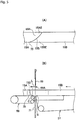
- the vibration applying members 31 have a function of regulating the movement of the food dough 15 to be subjected to the spreading action between the spreading rollers 27 arranged in a V-shape, in the width direction. Therefore, as shown in FIG. 4 , the shape of the vibration applying members 31 matches with the V-shape of the spreading rollers 27.
- the shape of the vibration applying members 31 is not particularly limited to this shape, and can be set according to conditions such as the property of the dough and a discharge width of the dough to be regulated.
- the spreading rollers 27 are arranged in a V-shape, it suffices that the distance between the spreading rollers 27 located on the lower side is smaller than the distance between the spreading rollers 27 located on the upper side.
- a diameter of the lower side spreading rollers 27 can be set larger than that of the upper side spreading rollers 27.
- a configuration in which the spreading rollers 27 face each other horizontally or a configuration in which the spreading rollers 27 are arranged in a zig-zag shape can be adopted.
- a carrying state detection sensor 55 that detects the carrying state of the food dough 15 to the spreading unit 25 is provided in order to control the transportation velocity of the belt conveyor 23 appropriately when the spreading action of the food dough 15 is performed in the spreading unit 25.
- the detection sensor 55 is, for example, a distance detection sensor using a laser beam, and detects a raised state of the food dough 15 near an entrance of the spreading unit 25.
- the transportation velocity of the belt conveyor 23 is controlled to be low by the control device 20.
- the transportation velocity of the belt conveyor 23 is controlled to be higher than that in the normal state. That is, the transportation velocity of the belt conveyor 23 is controlled appropriately corresponding to the spreading speed of the spreading unit 25.
- the food dough 15 spread to a predetermined thickness and predetermined width dimension by the spreading unit 25 is transferred to a measuring conveyor (a weighing conveyor) 59 constituting a measuring and cutting device by a transfer unit 57 provided at a position below the spreading unit 25.
- a measuring conveyor a weighing conveyor
- the food dough 15 is cut by a cutter device 61 which is another element constituting the measuring and cutting device.
- the transfer unit 57 is constituted by a transfer conveyor such as a belt conveyor, and a transfer direction of the transfer conveyor 57 is set to a direction orthogonal to (a direction intersecting) the transfer direction of the belt conveyor 23.
- the delivery direction of the food dough 15 by the belt conveyor 23 is a horizontal direction in FIG. 2
- the transfer direction by the spreading unit 25 is a vertical direction.
- the transfer direction of the food dough 15 by the transfer conveyor 57 is a direction orthogonal to the drawing of FIG. 2 . That is, the transfer directions of the food dough 15 by the belt conveyor 23, the spreading unit 25, and the transfer conveyor 57 are orthogonal to each other.
- an overlapping direction of the preceding food dough 15A and the following food dough 15B is vertical overlap on the belt conveyor 23, and at a position of the spreading unit and on the transfer conveyor 57, the overlapping direction is changed to right and left (lateral, horizontal) overlap in FIG. 2 . Therefore, the belt conveyor 23, the spreading unit 25, the transfer conveyor 57 and the like constitute a certain type of overlapping-relation converting unit that changes the overlapping relation between the rear end side of the preceding food dough 15A and the front end side of the following food dough 15B from a vertical relation to a lateral relation (a horizontal overlapping relation).
- a smoothing roller 63 (see FIG. 1 ) that smoothes the thickness of the food dough 15 transferred by the transfer conveyor 57 to a certain thickness is rotatably provided on an upper side near the downstream end of the transfer conveyor 57. Further, on an upstream side of the transfer conveyor 57, a bend-section detection sensor 65 that detects a change of a bent section of the food dough 15 transferred from the spreading unit 25 to the transfer conveyor 57 to the transfer direction of the transfer conveyor 57 is provided.
- the bend-section detection sensor 65 is a distance detection sensor similar to the detection sensor 55.
- the transfer speed of the transfer conveyor 57 is controlled to a lower speed, or the transfer speed of the spreading unit 25 is controlled to a higher speed.
- the transfer speed of the transfer conveyor 57 is controlled to a higher speed and the transfer speed of the spreading unit 25 is controlled to a lower speed. That is, the configuration is that, in a relation between the transfer speed of the spreading unit 25 and the transfer speed of the transfer conveyor 57, the speeds are controlled to be appropriate.
- the cutter device 61 includes upward and downward actuators 67U and 67L such as a fluid pressure cylinder placed on the mount 13, so as to face each other vertically.
- the upward and downward actuator 67U on the upper side is provided with a cutting blade 69 so as to be able to move vertically.
- the upward and downward actuator 67L on the lower side is provided with a support member 71 that supports the food dough 15 from below, facing the cutting blade 69 so as to be able to move vertically.
- the cutting blade 69 in the cutter device 61 when the food dough 15 is cut by the cutting blade 69 in the cutter device 61, a portion to be cut of the food dough 15 is supported from below by the support member 71.
- the cutting blade 69 comes in contact with an upper surface of the support member 71, to cut the food dough 15. Accordingly, the food dough 15 does not fall over downward in a lower part of the cut surface.
- a cut position 69A by the cutter device 61 can be set as close as possible to an upstream end side of the measuring conveyor 59. Therefore, a region from the cut position 69A of the cutter device 61 to a position 15D (a measurement start position C in the measuring conveyor 59) where the food dough 15 first comes in contact with the measuring conveyor 59, that is, a region where the weight is predicted in a state with the food dough 15 being floating (a predicted cut region) can be made shorter. Accordingly, measurement accuracy by the measuring conveyor 59 can be further improved.
- the cut piece 15C after the food dough 15 is measured by the measuring conveyor 59 and is cut by the cutter device 61 shown in FIG. 1 is measured again by a second measuring conveyor 73 arranged on the downstream side of the measuring conveyor 59, and is transferred to the next process.
- the second measuring conveyor 73 is for confirming whether the weight of the cut piece 15C which has been cut according to the measurement result of the measuring conveyor 59 is accurate.
- the measurement value by the measuring conveyor 59 is corrected by the control device 20 so that cutting by the cutter device 61 is performed accurately. Therefore, the cut piece 15C is accurately cut in a range having less error at all times with respect to the weight of the set value set beforehand.
- the overlapping relation between a rear end side 15AE (see FIGS. 5 ) of the preceding food dough 15A and a front end side 15BE of the following food dough 15B is converted from the vertical relation to the lateral relation (the horizontal relation) by the overlapping-relation converting unit, the overlapping relation between the rear end side 15AE of the preceding food dough 15A and the front end side 15BE of the following food dough 15B becomes the horizontal relation, and a connecting surface 15S thereof is transferred to the measuring conveyor 59 in a vertically extending state.
- the rear end side 15AE and the front end side 15BE adhere and are connected to each other by the spreading action of the spreading unit 25, and the connecting surface 15S is formed in an inclined state (not inclined vertically but inclined horizontally with respect to the transfer direction) from the preceding food dough 15A toward the following food dough 15B.
- a small depression 75 may be generated between a front end portion of the front end side 15BE and a side surface of the preceding food dough 15A.
- a lower surface of the food dough 15 placed on the transfer conveyor 57 and the weighing conveyor 59 in the overlapping portion, that is, a surface pressed by the vibration applying members 31 is formed in a smooth surface, and a depression such as the depression 75 is not formed on the lower surface of the food dough 15.
- the cut position 69A by the cutting blade 69 in the cutter device 61 is set at a position of the depression 75 or at a position close to the depression 75 is explained here.
- the depression 75 is on the side surface of the food dough 15, not at a position facing a delivery surface of the measuring conveyor 59.
- the overlapping portion of the food dough 15 is placed on an upper surface of the measuring conveyor 59 or is in a state close thereto.
- a portion (of a distance L) of the food dough 15 from the cut position 69A to the contact position 15D where the food dough 15 first comes in contact with the measuring conveyor 59 and a portion of the food dough 15 from the cut position 69A to a separating position S at which the food dough 15 is separated from the transfer conveyor 57 are in a floating state. Therefore, the weight of the food dough 15 in the portion corresponding to the distance L is not measured actually but is calculated based on the measurement value of the measuring conveyor 59, and thus the portion becomes a predicted cut region.
- the rear end side 15AE and the front end side 15BE adhere and are connected to each other with the inclined surface 15S serving as a boundary, because the overlapping relation of the rear end side 15AE and the front end side 15BE is the horizontal relation, the rear end side 15AE and the front end side 15BE are directly placed on the measuring conveyor 59, and the weight of the food dough 15 acts downward to the measuring conveyor 59.
- a measurement error of the food dough 15 by the measuring conveyor 59 can be reduced, and an error in a predicted weight in the predicted cut region can be suppressed further, as compared to a case where the front end side 15BE overlaps on an upper side of the rear end side 15AE.
- the contact position 15D of the food dough 15 can be matched with the measurement start position C of the measuring conveyor 59 by forming the surface of the food dough 15 placed on the measuring conveyor 59 in a smooth surface. Accordingly, the length of the distance L is stabilized, and the cut piece 15C can be cut with a more accurate weight.
- FIG. 6 shows a second embodiment.
- the transfer direction of the food dough 15 by the transfer conveyor 57 is leftward in FIG. 6 , which is an opposite direction to the transfer direction of the food dough by the belt conveyor 23.
- the food dough 15 spread by the spreading unit 25 can be divided into two rows or more.
- an overlapping-relation converting unit 79 converts the overlapping relation between the rear end side 15AE of the preceding food dough 15A and the front end side 15BE of the following food dough 15B from the vertical relation to the horizontal (lateral) relation, and transfers the food dough 15.
- the food dough 15 divided into the respective rows is measured to a predetermined weight set beforehand by each measuring conveyor 59, and is cut into the cut piece 15C by each cutting blade 69 for each row.
- the front end side 15BE of the following food dough 15B is laminated on the upper surface of the rear end side 15AE of the preceding food dough 15A by the cutting device 19 to form a vertical overlapping portion.
- the overlapping-relation converting unit converts the overlapping relation between the rear end side 15AE (see FIGS. 5 ) of the preceding food dough 15A and the front end side 15BE of the following food dough 15B from the vertical relation to the lateral (horizontal) relation
- the overlapping relation of the rear end side 15AE of the preceding food dough 15A and the front end side 15BE of the following food dough 15B becomes the horizontal relation.
- the connecting surface 15S thereof is transferred to the measuring conveyor 59 in a vertically extending state.
- the portion (the distance L) from the cut position 69A to the contact position 15D where the food dough 15 first comes in contact with the measuring conveyor 59 and the portion from the cut position 69A to the separating position S at which the food dough 15 is separated from the transfer conveyor 57 are in a floating state.
- the rear end side 15AE and the front end side 15BE are directly placed on the measuring conveyor 59 and the weight of the food dough 15 acts on the measuring conveyor 59 in the vertical direction. Accordingly, a measurement error of the food dough 15 by the measuring conveyor 59 can be reduced, as compared to the case where the front end side 15BE is overlapped on an upper side of the rear end side 15AE.
- FIG. 7 shows a third embodiment.
- the rear end side 15AE and the front end side 15BE can be placed beforehand so as to be overlapped on each other horizontally on the belt conveyor 23 and can be overlapped so as to adhere and be connected to each other.
- the transfer direction of the food dough 15 by the transfer conveyor 57 is rightward in FIG. 7 , and is the same direction as the transfer direction of the food dough by the belt conveyor 23. Accordingly, an overlapping portion formed by laminating the front end side 15BE of the following food dough 15B on an upper surface of the rear end side 15AE of the preceding food dough 15A by the cutting device 19 is maintained as it is and is delivered.
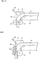
- FIG. 10 shows a fourth embodiment.
- the vibration applying members (the width regulating members) 31 an inclination of the opposite faces can be formed in a truncated shape, as shown in FIG. 10.
- FIG. 10 is an explanatory diagram schematically showing another form of the vibration applying members (width regulating members) 31.
- the vibration applying members (the width regulating member) 31 face each other, as shown in FIGS. 1 and 3 , so that an opposite distance becomes narrower as moving downward and the lower side of each vibration applying member 31 gradually becomes thicker.
- the vibration applying members 31 can be provided so that the opposite distance becomes wider as moving downward and the lower side of each vibration applying member 31 gradually becomes thinner.
- the transfer direction of the food dough 15 by the transfer conveyor 57 is leftward in FIG. 1 .
- the transfer direction of the food dough 15 by the transfer conveyor 57 is vertical to the drawing of FIG. 10 , and the food dough 15 is transferred in a direction protruding this way from the drawing.
- FIG. 11 shows a fifth embodiment.
- the fifth embodiment shows a case where the food dough 15 is transferred in a state with the overlapping relation of the rear end side 15AE of the preceding food dough 15A and the front end side 15BE of the following food dough 15B being maintained in the vertical relation, without using the overlapping-relation converting unit 79 in the second embodiment shown in FIG. 6 .
- Three spacing and delivering devices 81 are arranged in parallel on the downstream side of the transfer conveyor 57.
- the spacing and delivering devices 81 are delivery conveyors that respectively space the food dough 15X, 15Y, and 15Z divided by the cutter 77 in the width direction and transfer the food dough 15 for each row.
- three measuring conveyors 59 and second measuring conveyors (not shown) similar to those in the first embodiment are continuously installed for each row on the downstream side of each of the spacing and delivering devices 81.
- the cutter device 61 including three cutting blades 69 is provided between the respective spacing and delivering devices 81 and the respective measuring conveyors.
- the bend-section detection sensor 65 that detects a change in the transfer direction of the transfer conveyor 57, of the bend section of the food dough 15 transferred from the spreading unit 25 to the transfer conveyor 57 is provided on an upstream side of the transfer conveyor 57 (on the right side in FIG. 11 ).
- the support members 71 are respectively arranged between the three spacing and delivering devices 81 arranged in parallel and the three measuring conveyors 59 arranged in parallel. The support members 71 support the food dough 15X, 15Y, and 15Z, respectively when the food dough 15X, 15Y, and 15Z are respectively cut by the three cutting blades 69.
- FIG. 12 shows a sixth embodiment.
- the transfer direction of the food dough 15 by the transfer conveyor 57 is rightward in FIG. 12 , and is the same direction as the transfer direction of the food dough by the belt conveyor 23. Accordingly, the overlapping portion formed by laminating the front end side 15BE of the following food dough 15B on the upper surface of the rear end side 15AE of the preceding food dough 15A by the cutting device 19 is maintained as it is and is delivered.
- FIG. 13 shows a seventh embodiment.
- a flow direction of the food dough 15 can be not only the vertical direction but also a direction inclined to the horizontal direction. Further, the inclination angle thereof can be adjustable within a range of, for example, from 45° to 90°.
- a height of a region occupied by the spreading unit 25 can be set low by arranging the plurality of opposite spreading rollers 27 so that the flow of the food dough 15 is inclined. Accordingly, the height of the entire food dough spreading device 11 can be set low, thereby enabling to facilitate supply of the food dough 15.
- the spreading rollers 27 can be configured with one pair of opposite rollers (two) or with a relation in which one roller opposes three rollers, and the like.
- the width dimension of the food dough 15 to be spread can be adjusted by reciprocatively vibrating the pair of vibration applying members (the width regulating members) 31 provided between the spreading rollers 27 in the width direction (the longitudinal direction of the spreading rollers 27) so as to be operated to approach and be separated from each other. Further, the both side edges in the width direction of the food dough are repeatedly subjected to compression and release, and application and release of the internal stress are repeated, so that the internal stress does not remain therein.
- the food dough 15 can be gradually spread to be made thinner even if the configuration is such that three spreading rollers 27 are provided on an upper surface side of the food dough 15 and one large spreading roller 27 is provided on a lower surface side of the food dough 15.
- the configuration is such that a distance between the three spreading rollers 27 on the upper surface side of the food dough 15 and the one large spreading roller 27 on the lower surface side of the food dough 15 (a distance shown by an arrow in FIG. 15 ) becomes gradually narrower as moving downward from the uppermost spreading roller 27 of the three spreading rollers 27 toward the lowermost spreading roller 27. Accordingly, by the configuration in which the distance gradually becomes narrow, identical effects can be achieved as in the V-shaped arrangement described above.
- the opposite distance between the pair of vibration applying members 31 can be such that the lower side is narrower than the upper side and the opposite distance of the spreading roller 27 can be such that the lower side is wider than the upper side.
- the opposite distance between the pair of vibration applying members 31 can be such that the lower side (the downstream side) is provided to be narrower than the upper side (the upstream side) as described above, and the opposite distance between the spreading rollers 27 can be provided to be the same from the upper side (the upstream side) to the lower side (the downstream side).
- the speed of the spreading rollers 27 can be set so as to be the same circumferential velocity from the spreading roller 27 on the upper side (the upstream side) to the spreading roller 27 on the lower side (the downstream side).
- the measuring conveyor (the weighing conveyor) 59 and the cutter device 61 constituting the measuring and cutting device according to the invention of the present application are not limited to the above embodiments, and even if the measuring and cutting device is replaced by a measuring and cutting device disclosed in, for example, European Patent Publication No. 1174032 , similar effects can be achieved.
- both sides in the width direction of the food dough 15 spread by the spreading unit 25 are regulated by the vibration applying members 31, and vibration is applied to the both sides of the food dough 15 by the vibration applying members 31, the both sides of the food dough 15 in the width direction are formed in a smooth surface, without having any irregularities in the both sides. Therefore, when the food dough 15 is divided into a plurality of rows as described above, trimming of the both sides is not required. Accordingly, there is no portion to be removed by trimming, and waste by trimming can be eliminated.
Landscapes
- Life Sciences & Earth Sciences (AREA)
- Engineering & Computer Science (AREA)
- Food Science & Technology (AREA)
- Manufacturing And Processing Devices For Dough (AREA)
- Noodles (AREA)
- General Preparation And Processing Of Foods (AREA)
Priority Applications (1)
| Application Number | Priority Date | Filing Date | Title |
|---|---|---|---|
| PL13797581T PL2856878T3 (pl) | 2012-06-01 | 2013-05-28 | Urządzenie do rozwałkowywania ciasta spożywczego i sposób rozwałkowywania ciasta spożywczego |
Applications Claiming Priority (2)
| Application Number | Priority Date | Filing Date | Title |
|---|---|---|---|
| JP2012125858 | 2012-06-01 | ||
| PCT/JP2013/064746 WO2013180115A1 (ja) | 2012-06-01 | 2013-05-28 | 食品生地延展装置及び食品生地延展方法 |
Publications (3)
| Publication Number | Publication Date |
|---|---|
| EP2856878A1 EP2856878A1 (en) | 2015-04-08 |
| EP2856878A4 EP2856878A4 (en) | 2016-04-27 |
| EP2856878B1 true EP2856878B1 (en) | 2019-10-09 |
Family
ID=49673307
Family Applications (1)
| Application Number | Title | Priority Date | Filing Date |
|---|---|---|---|
| EP13797581.9A Active EP2856878B1 (en) | 2012-06-01 | 2013-05-28 | Food dough spreading device and food dough spreading method |
Country Status (18)
| Country | Link |
|---|---|
| US (1) | US10383341B2 (ja) |
| EP (1) | EP2856878B1 (ja) |
| JP (2) | JP6076338B2 (ja) |
| KR (1) | KR101670711B1 (ja) |
| CN (1) | CN104334026B (ja) |
| AU (1) | AU2013268506B2 (ja) |
| BR (1) | BR112014030036B1 (ja) |
| CA (1) | CA2873683C (ja) |
| ES (1) | ES2759796T3 (ja) |
| HK (1) | HK1202226A1 (ja) |
| IN (1) | IN2014DN10976A (ja) |
| MY (1) | MY174586A (ja) |
| PH (1) | PH12014502424A1 (ja) |
| PL (1) | PL2856878T3 (ja) |
| RU (1) | RU2581231C1 (ja) |
| SG (1) | SG11201407157WA (ja) |
| TW (1) | TWI587789B (ja) |
| WO (1) | WO2013180115A1 (ja) |
Families Citing this family (8)
| Publication number | Priority date | Publication date | Assignee | Title |
|---|---|---|---|---|
| JP5914178B2 (ja) * | 2012-06-01 | 2016-05-11 | レオン自動機株式会社 | 食品生地の計量切断方法及び装置 |
| JP2015149922A (ja) * | 2014-02-12 | 2015-08-24 | レオン自動機株式会社 | 角形のパンを製造するための生地玉を準備する方法 |
| MY189088A (en) * | 2015-06-08 | 2022-01-25 | Rheon Automatic Machinery Co | Shaping method for dough pieces and shaping apparatus for same |
| DE102016120042B4 (de) * | 2016-10-20 | 2021-04-29 | Fritsch Bakery Technologies GmbH & Co. KG | Vorrichtung zum, insbesondere kontinuierlichen, gravimetrischen Dosieren und Portionieren einzelner Teigportionen aus einer Teigmasse |
| IT201600129870A1 (it) * | 2016-12-22 | 2018-06-22 | Tecnofill S R L | Dosatore di prodotti alimentari, in particolare in forma cubettata, sminuzzata o sfilacciata. |
| IT201900011220A1 (it) * | 2019-07-09 | 2021-01-09 | Gianvito Campanella | Apparato divaricatore e metodo per divaricare cordoni di impasto alimentare per la produzione di grissini, taralli o altri prodotti alimentari realizzati a partire da cordoni di impasto alimentare |
| JP7328351B2 (ja) * | 2019-12-02 | 2023-08-16 | レオン自動機株式会社 | 食品生地整形装置 |
| CN113197233B (zh) * | 2021-04-28 | 2022-11-04 | 安徽玺业智能科技有限公司 | 一种包子馒头圆饼组合机 |
Citations (4)
| Publication number | Priority date | Publication date | Assignee | Title |
|---|---|---|---|---|
| EP0197671A1 (en) * | 1985-03-12 | 1986-10-15 | Rheon Automatic Machinery Co. Ltd. | Dough handling apparatus |
| EP0545725A1 (en) * | 1991-12-05 | 1993-06-09 | Rheon Automatic Machinery Co., Ltd. | Method and apparatus for supplying a uniform strip of bread dough |
| JP2001321061A (ja) * | 2000-05-17 | 2001-11-20 | Kojima Press Co Ltd | 生地延ばし装置 |
| EP1174032A1 (en) * | 2000-02-21 | 2002-01-23 | Rheon Automatic Machinery Co., Ltd. | Method and device for feeding food material |
Family Cites Families (25)
| Publication number | Priority date | Publication date | Assignee | Title |
|---|---|---|---|---|
| JPS6354334A (ja) | 1986-08-22 | 1988-03-08 | Mitsubishi Chem Ind Ltd | ジテルペン化合物 |
| JPH0653039B2 (ja) * | 1987-04-01 | 1994-07-20 | レオン自動機株式会社 | パン生地等の均一な連続生地の供給方法及び装置 |
| NL8702866A (nl) * | 1987-11-30 | 1989-06-16 | Werner & Pfleiderer Haton Bv | Deegopbolmachine. |
| JPH0683627B2 (ja) | 1988-01-27 | 1994-10-26 | レオン自動機株式会社 | パン又はペストリーの製造方法 |
| JPH01206942A (ja) * | 1988-02-15 | 1989-08-21 | Rheon Autom Mach Co Ltd | パン生地等の延展成形方法及び装置 |
| JPH0383535A (ja) * | 1989-08-28 | 1991-04-09 | Rheon Autom Mach Co Ltd | パン生地の定量分割方法および装置 |
| JPH0697934B2 (ja) | 1990-01-16 | 1994-12-07 | レオン自動機株式会社 | 生地延展方法および装置 |
| JPH04152835A (ja) * | 1990-02-16 | 1992-05-26 | Rheon Autom Mach Co Ltd | 生地延展ローラー |
| JP2579826B2 (ja) | 1990-04-17 | 1997-02-12 | レオン自動機 株式会社 | 連続した帯状パン生地を製造する方法及び装置 |
| JP2510890B2 (ja) * | 1990-09-20 | 1996-06-26 | レオン自動機株式会社 | 生地延展方法及び装置 |
| JP2917002B2 (ja) * | 1995-05-02 | 1999-07-12 | レオン自動機株式会社 | パン生地等の延展方法および装置 |
| JP2917003B2 (ja) * | 1995-05-22 | 1999-07-12 | レオン自動機株式会社 | パン生地等の連続的定量供給方法および装置 |
| TW313513B (ja) * | 1995-05-22 | 1997-08-21 | Reon Zidoki Kk | |
| JP2750843B2 (ja) * | 1996-01-09 | 1998-05-13 | レオン自動機株式会社 | 分割されたパン生地の連結供給方法および装置 |
| MY115084A (en) * | 1996-05-22 | 2003-03-31 | Rheon Automatic Machinery Co | Method and apparatus for continuously and quantitatively supplying bread dough |
| JP3015867B2 (ja) * | 1996-11-29 | 2000-03-06 | レオン自動機株式会社 | 食品生地の連結供給方法および装置 |
| JP3056697B2 (ja) * | 1997-06-06 | 2000-06-26 | レオン自動機株式会社 | パン生地の連続的定量供給装置 |
| JPH11308961A (ja) * | 1998-04-28 | 1999-11-09 | Rheon Autom Mach Co Ltd | パン生地等の延展装置 |
| US6159518A (en) * | 1999-10-01 | 2000-12-12 | Wilson; Barry F. | Process and wire assembly for separating dough sheet from rotating roller surface |
| MXPA04012331A (es) * | 2002-06-10 | 2005-04-08 | Rheon Automatic Machinery Co | Aparato y metodo para batir y moler una banda de masa para alimento. |
| JP4311737B2 (ja) | 2004-08-23 | 2009-08-12 | レオン自動機株式会社 | 積層食品生地の成形方法および装置 |
| JP2006314266A (ja) * | 2005-05-13 | 2006-11-24 | Yamato Seisakusho:Kk | 麺生地ロール圧延装置 |
| CN2822224Y (zh) * | 2005-07-28 | 2006-10-04 | 北京腾威机械有限公司 | 一种面片压延机组 |
| JP2009278934A (ja) | 2008-05-23 | 2009-12-03 | Rheon Automatic Machinerty Co Ltd | 食品生地の切断方法及び装置 |
| JP2010088423A (ja) | 2008-09-09 | 2010-04-22 | Rheon Automatic Machinerty Co Ltd | 食品生地の延展方法及び装置 |
-
2013
- 2013-05-28 MY MYPI2014703259A patent/MY174586A/en unknown
- 2013-05-28 CA CA2873683A patent/CA2873683C/en active Active
- 2013-05-28 RU RU2014152831/13A patent/RU2581231C1/ru active
- 2013-05-28 CN CN201380027557.8A patent/CN104334026B/zh active Active
- 2013-05-28 WO PCT/JP2013/064746 patent/WO2013180115A1/ja active Application Filing
- 2013-05-28 BR BR112014030036-4A patent/BR112014030036B1/pt active IP Right Grant
- 2013-05-28 KR KR1020147033510A patent/KR101670711B1/ko active IP Right Grant
- 2013-05-28 IN IN10976DEN2014 patent/IN2014DN10976A/en unknown
- 2013-05-28 EP EP13797581.9A patent/EP2856878B1/en active Active
- 2013-05-28 AU AU2013268506A patent/AU2013268506B2/en active Active
- 2013-05-28 PL PL13797581T patent/PL2856878T3/pl unknown
- 2013-05-28 ES ES13797581T patent/ES2759796T3/es active Active
- 2013-05-28 SG SG11201407157WA patent/SG11201407157WA/en unknown
- 2013-05-28 US US14/398,015 patent/US10383341B2/en active Active
- 2013-05-28 JP JP2014518673A patent/JP6076338B2/ja active Active
- 2013-05-31 TW TW102119423A patent/TWI587789B/zh active
-
2014
- 2014-10-28 PH PH12014502424A patent/PH12014502424A1/en unknown
-
2015
- 2015-03-18 HK HK15102787.6A patent/HK1202226A1/zh unknown
-
2017
- 2017-01-10 JP JP2017001876A patent/JP6279113B2/ja active Active
Patent Citations (4)
| Publication number | Priority date | Publication date | Assignee | Title |
|---|---|---|---|---|
| EP0197671A1 (en) * | 1985-03-12 | 1986-10-15 | Rheon Automatic Machinery Co. Ltd. | Dough handling apparatus |
| EP0545725A1 (en) * | 1991-12-05 | 1993-06-09 | Rheon Automatic Machinery Co., Ltd. | Method and apparatus for supplying a uniform strip of bread dough |
| EP1174032A1 (en) * | 2000-02-21 | 2002-01-23 | Rheon Automatic Machinery Co., Ltd. | Method and device for feeding food material |
| JP2001321061A (ja) * | 2000-05-17 | 2001-11-20 | Kojima Press Co Ltd | 生地延ばし装置 |
Also Published As
| Publication number | Publication date |
|---|---|
| AU2013268506B2 (en) | 2015-10-01 |
| JP2017079784A (ja) | 2017-05-18 |
| HK1202226A1 (zh) | 2015-09-25 |
| WO2013180115A1 (ja) | 2013-12-05 |
| CA2873683C (en) | 2016-04-05 |
| JP6076338B2 (ja) | 2017-02-08 |
| KR101670711B1 (ko) | 2016-10-31 |
| RU2581231C1 (ru) | 2016-04-20 |
| KR20150016285A (ko) | 2015-02-11 |
| CN104334026A (zh) | 2015-02-04 |
| PH12014502424B1 (en) | 2015-01-12 |
| US20150110930A1 (en) | 2015-04-23 |
| TWI587789B (zh) | 2017-06-21 |
| EP2856878A1 (en) | 2015-04-08 |
| BR112014030036A2 (pt) | 2017-06-27 |
| BR112014030036B1 (pt) | 2020-03-17 |
| MY174586A (en) | 2020-04-28 |
| TW201410152A (zh) | 2014-03-16 |
| CA2873683A1 (en) | 2013-12-05 |
| CN104334026B (zh) | 2016-06-15 |
| PL2856878T3 (pl) | 2020-06-01 |
| IN2014DN10976A (ja) | 2015-09-18 |
| PH12014502424A1 (en) | 2015-01-12 |
| JPWO2013180115A1 (ja) | 2016-01-21 |
| EP2856878A4 (en) | 2016-04-27 |
| SG11201407157WA (en) | 2014-12-30 |
| AU2013268506A1 (en) | 2014-11-27 |
| JP6279113B2 (ja) | 2018-02-14 |
| US10383341B2 (en) | 2019-08-20 |
| ES2759796T3 (es) | 2020-05-12 |
Similar Documents
| Publication | Publication Date | Title |
|---|---|---|
| EP2856878B1 (en) | Food dough spreading device and food dough spreading method | |
| US7578232B2 (en) | Apparatus and method for manufacturing bread | |
| KR100244993B1 (ko) | 빵 반죽 시트 형성장치 및 방법 | |
| KR20200079298A (ko) | 시트를 연속 스트립으로 변환하기 위한 장치 및 방법 | |
| JP6362187B2 (ja) | 連続生地の秤量切断システムおよび方法 | |
| JP5895310B2 (ja) | 包装材製造機械内における扁平な基材の移送装置 | |
| JP5914178B2 (ja) | 食品生地の計量切断方法及び装置 | |
| JP6408013B2 (ja) | 連続生地の秤量切断システム | |
| JP7314471B2 (ja) | 分離装置 | |
| JP4649235B2 (ja) | 食パンのスライス包装方法及び装置 | |
| KR20200082381A (ko) | 면 가공장치 | |
| WO2010143460A1 (ja) | 食品生地切断装置 | |
| KR101888757B1 (ko) | 식품포장이 용이한 포장지 및 그 성형장치 | |
| JP7337451B2 (ja) | 成型食品の積層方法 | |
| WO2016064723A1 (en) | Gum strip cutting and handling system for slab wrapping machine | |
| JP4313976B2 (ja) | 移送物の間隔開け方法及びその装置並びにパイ生地等の被加工物の梱包の前処理装置 | |
| RU2271661C2 (ru) | Устройство и способ для изготовления хлеба | |
| JP6122618B6 (ja) | おにぎり製造装置 | |
| JP6122618B2 (ja) | おにぎり製造装置 | |
| JP2016175097A (ja) | 金属薄板の加工装置及び加工方法 | |
| WO2007052228A2 (en) | Apparatus and method for laminating a material |
Legal Events
| Date | Code | Title | Description |
|---|---|---|---|
| PUAI | Public reference made under article 153(3) epc to a published international application that has entered the european phase |
Free format text: ORIGINAL CODE: 0009012 |
|
| 17P | Request for examination filed |
Effective date: 20141119 |
|
| AK | Designated contracting states |
Kind code of ref document: A1 Designated state(s): AL AT BE BG CH CY CZ DE DK EE ES FI FR GB GR HR HU IE IS IT LI LT LU LV MC MK MT NL NO PL PT RO RS SE SI SK SM TR |
|
| AX | Request for extension of the european patent |
Extension state: BA ME |
|
| DAX | Request for extension of the european patent (deleted) | ||
| RA4 | Supplementary search report drawn up and despatched (corrected) |
Effective date: 20160330 |
|
| RIC1 | Information provided on ipc code assigned before grant |
Ipc: A21C 3/02 20060101AFI20160322BHEP |
|
| STAA | Information on the status of an ep patent application or granted ep patent |
Free format text: STATUS: EXAMINATION IS IN PROGRESS |
|
| 17Q | First examination report despatched |
Effective date: 20170705 |
|
| GRAP | Despatch of communication of intention to grant a patent |
Free format text: ORIGINAL CODE: EPIDOSNIGR1 |
|
| STAA | Information on the status of an ep patent application or granted ep patent |
Free format text: STATUS: GRANT OF PATENT IS INTENDED |
|
| INTG | Intention to grant announced |
Effective date: 20190507 |
|
| GRAS | Grant fee paid |
Free format text: ORIGINAL CODE: EPIDOSNIGR3 |
|
| GRAA | (expected) grant |
Free format text: ORIGINAL CODE: 0009210 |
|
| STAA | Information on the status of an ep patent application or granted ep patent |
Free format text: STATUS: THE PATENT HAS BEEN GRANTED |
|
| AK | Designated contracting states |
Kind code of ref document: B1 Designated state(s): AL AT BE BG CH CY CZ DE DK EE ES FI FR GB GR HR HU IE IS IT LI LT LU LV MC MK MT NL NO PL PT RO RS SE SI SK SM TR |
|
| REG | Reference to a national code |
Ref country code: GB Ref legal event code: FG4D |
|
| REG | Reference to a national code |
Ref country code: CH Ref legal event code: EP |
|
| REG | Reference to a national code |
Ref country code: IE Ref legal event code: FG4D |
|
| REG | Reference to a national code |
Ref country code: DE Ref legal event code: R096 Ref document number: 602013061529 Country of ref document: DE |
|
| REG | Reference to a national code |
Ref country code: AT Ref legal event code: REF Ref document number: 1187725 Country of ref document: AT Kind code of ref document: T Effective date: 20191115 |
|
| REG | Reference to a national code |
Ref country code: NL Ref legal event code: FP |
|
| REG | Reference to a national code |
Ref country code: LT Ref legal event code: MG4D |
|
| REG | Reference to a national code |
Ref country code: AT Ref legal event code: MK05 Ref document number: 1187725 Country of ref document: AT Kind code of ref document: T Effective date: 20191009 |
|
| REG | Reference to a national code |
Ref country code: GR Ref legal event code: EP Ref document number: 20200400028 Country of ref document: GR Effective date: 20200318 |
|
| PG25 | Lapsed in a contracting state [announced via postgrant information from national office to epo] |
Ref country code: AT Free format text: LAPSE BECAUSE OF FAILURE TO SUBMIT A TRANSLATION OF THE DESCRIPTION OR TO PAY THE FEE WITHIN THE PRESCRIBED TIME-LIMIT Effective date: 20191009 Ref country code: LT Free format text: LAPSE BECAUSE OF FAILURE TO SUBMIT A TRANSLATION OF THE DESCRIPTION OR TO PAY THE FEE WITHIN THE PRESCRIBED TIME-LIMIT Effective date: 20191009 Ref country code: LV Free format text: LAPSE BECAUSE OF FAILURE TO SUBMIT A TRANSLATION OF THE DESCRIPTION OR TO PAY THE FEE WITHIN THE PRESCRIBED TIME-LIMIT Effective date: 20191009 Ref country code: SE Free format text: LAPSE BECAUSE OF FAILURE TO SUBMIT A TRANSLATION OF THE DESCRIPTION OR TO PAY THE FEE WITHIN THE PRESCRIBED TIME-LIMIT Effective date: 20191009 Ref country code: BG Free format text: LAPSE BECAUSE OF FAILURE TO SUBMIT A TRANSLATION OF THE DESCRIPTION OR TO PAY THE FEE WITHIN THE PRESCRIBED TIME-LIMIT Effective date: 20200109 Ref country code: FI Free format text: LAPSE BECAUSE OF FAILURE TO SUBMIT A TRANSLATION OF THE DESCRIPTION OR TO PAY THE FEE WITHIN THE PRESCRIBED TIME-LIMIT Effective date: 20191009 Ref country code: PT Free format text: LAPSE BECAUSE OF FAILURE TO SUBMIT A TRANSLATION OF THE DESCRIPTION OR TO PAY THE FEE WITHIN THE PRESCRIBED TIME-LIMIT Effective date: 20200210 Ref country code: NO Free format text: LAPSE BECAUSE OF FAILURE TO SUBMIT A TRANSLATION OF THE DESCRIPTION OR TO PAY THE FEE WITHIN THE PRESCRIBED TIME-LIMIT Effective date: 20200109 |
|
| REG | Reference to a national code |
Ref country code: ES Ref legal event code: FG2A Ref document number: 2759796 Country of ref document: ES Kind code of ref document: T3 Effective date: 20200512 |
|
| PG25 | Lapsed in a contracting state [announced via postgrant information from national office to epo] |
Ref country code: RS Free format text: LAPSE BECAUSE OF FAILURE TO SUBMIT A TRANSLATION OF THE DESCRIPTION OR TO PAY THE FEE WITHIN THE PRESCRIBED TIME-LIMIT Effective date: 20191009 Ref country code: HR Free format text: LAPSE BECAUSE OF FAILURE TO SUBMIT A TRANSLATION OF THE DESCRIPTION OR TO PAY THE FEE WITHIN THE PRESCRIBED TIME-LIMIT Effective date: 20191009 Ref country code: IS Free format text: LAPSE BECAUSE OF FAILURE TO SUBMIT A TRANSLATION OF THE DESCRIPTION OR TO PAY THE FEE WITHIN THE PRESCRIBED TIME-LIMIT Effective date: 20200224 |
|
| PG25 | Lapsed in a contracting state [announced via postgrant information from national office to epo] |
Ref country code: AL Free format text: LAPSE BECAUSE OF FAILURE TO SUBMIT A TRANSLATION OF THE DESCRIPTION OR TO PAY THE FEE WITHIN THE PRESCRIBED TIME-LIMIT Effective date: 20191009 |
|
| REG | Reference to a national code |
Ref country code: DE Ref legal event code: R097 Ref document number: 602013061529 Country of ref document: DE |
|
| PG2D | Information on lapse in contracting state deleted |
Ref country code: IS |
|
| PG25 | Lapsed in a contracting state [announced via postgrant information from national office to epo] |
Ref country code: CZ Free format text: LAPSE BECAUSE OF FAILURE TO SUBMIT A TRANSLATION OF THE DESCRIPTION OR TO PAY THE FEE WITHIN THE PRESCRIBED TIME-LIMIT Effective date: 20191009 Ref country code: RO Free format text: LAPSE BECAUSE OF FAILURE TO SUBMIT A TRANSLATION OF THE DESCRIPTION OR TO PAY THE FEE WITHIN THE PRESCRIBED TIME-LIMIT Effective date: 20191009 Ref country code: EE Free format text: LAPSE BECAUSE OF FAILURE TO SUBMIT A TRANSLATION OF THE DESCRIPTION OR TO PAY THE FEE WITHIN THE PRESCRIBED TIME-LIMIT Effective date: 20191009 Ref country code: DK Free format text: LAPSE BECAUSE OF FAILURE TO SUBMIT A TRANSLATION OF THE DESCRIPTION OR TO PAY THE FEE WITHIN THE PRESCRIBED TIME-LIMIT Effective date: 20191009 Ref country code: IS Free format text: LAPSE BECAUSE OF FAILURE TO SUBMIT A TRANSLATION OF THE DESCRIPTION OR TO PAY THE FEE WITHIN THE PRESCRIBED TIME-LIMIT Effective date: 20200209 |
|
| PLBE | No opposition filed within time limit |
Free format text: ORIGINAL CODE: 0009261 |
|
| STAA | Information on the status of an ep patent application or granted ep patent |
Free format text: STATUS: NO OPPOSITION FILED WITHIN TIME LIMIT |
|
| PG25 | Lapsed in a contracting state [announced via postgrant information from national office to epo] |
Ref country code: SK Free format text: LAPSE BECAUSE OF FAILURE TO SUBMIT A TRANSLATION OF THE DESCRIPTION OR TO PAY THE FEE WITHIN THE PRESCRIBED TIME-LIMIT Effective date: 20191009 Ref country code: SM Free format text: LAPSE BECAUSE OF FAILURE TO SUBMIT A TRANSLATION OF THE DESCRIPTION OR TO PAY THE FEE WITHIN THE PRESCRIBED TIME-LIMIT Effective date: 20191009 |
|
| 26N | No opposition filed |
Effective date: 20200710 |
|
| PG25 | Lapsed in a contracting state [announced via postgrant information from national office to epo] |
Ref country code: SI Free format text: LAPSE BECAUSE OF FAILURE TO SUBMIT A TRANSLATION OF THE DESCRIPTION OR TO PAY THE FEE WITHIN THE PRESCRIBED TIME-LIMIT Effective date: 20191009 |
|
| PG25 | Lapsed in a contracting state [announced via postgrant information from national office to epo] |
Ref country code: MC Free format text: LAPSE BECAUSE OF FAILURE TO SUBMIT A TRANSLATION OF THE DESCRIPTION OR TO PAY THE FEE WITHIN THE PRESCRIBED TIME-LIMIT Effective date: 20191009 |
|
| REG | Reference to a national code |
Ref country code: BE Ref legal event code: MM Effective date: 20200531 |
|
| PG25 | Lapsed in a contracting state [announced via postgrant information from national office to epo] |
Ref country code: LU Free format text: LAPSE BECAUSE OF NON-PAYMENT OF DUE FEES Effective date: 20200528 |
|
| PG25 | Lapsed in a contracting state [announced via postgrant information from national office to epo] |
Ref country code: IE Free format text: LAPSE BECAUSE OF NON-PAYMENT OF DUE FEES Effective date: 20200528 |
|
| PG25 | Lapsed in a contracting state [announced via postgrant information from national office to epo] |
Ref country code: BE Free format text: LAPSE BECAUSE OF NON-PAYMENT OF DUE FEES Effective date: 20200531 |
|
| PG25 | Lapsed in a contracting state [announced via postgrant information from national office to epo] |
Ref country code: TR Free format text: LAPSE BECAUSE OF FAILURE TO SUBMIT A TRANSLATION OF THE DESCRIPTION OR TO PAY THE FEE WITHIN THE PRESCRIBED TIME-LIMIT Effective date: 20191009 Ref country code: MT Free format text: LAPSE BECAUSE OF FAILURE TO SUBMIT A TRANSLATION OF THE DESCRIPTION OR TO PAY THE FEE WITHIN THE PRESCRIBED TIME-LIMIT Effective date: 20191009 Ref country code: CY Free format text: LAPSE BECAUSE OF FAILURE TO SUBMIT A TRANSLATION OF THE DESCRIPTION OR TO PAY THE FEE WITHIN THE PRESCRIBED TIME-LIMIT Effective date: 20191009 |
|
| PG25 | Lapsed in a contracting state [announced via postgrant information from national office to epo] |
Ref country code: MK Free format text: LAPSE BECAUSE OF FAILURE TO SUBMIT A TRANSLATION OF THE DESCRIPTION OR TO PAY THE FEE WITHIN THE PRESCRIBED TIME-LIMIT Effective date: 20191009 |
|
| PGFP | Annual fee paid to national office [announced via postgrant information from national office to epo] |
Ref country code: NL Payment date: 20230519 Year of fee payment: 11 Ref country code: IT Payment date: 20230526 Year of fee payment: 11 Ref country code: FR Payment date: 20230526 Year of fee payment: 11 Ref country code: DE Payment date: 20220620 Year of fee payment: 11 Ref country code: CH Payment date: 20230602 Year of fee payment: 11 |
|
| P01 | Opt-out of the competence of the unified patent court (upc) registered |
Effective date: 20230626 |
|
| PGFP | Annual fee paid to national office [announced via postgrant information from national office to epo] |
Ref country code: PL Payment date: 20230519 Year of fee payment: 11 Ref country code: GR Payment date: 20230522 Year of fee payment: 11 |
|
| PGFP | Annual fee paid to national office [announced via postgrant information from national office to epo] |
Ref country code: ES Payment date: 20230725 Year of fee payment: 11 Ref country code: GB Payment date: 20230524 Year of fee payment: 11 |