EP2825354B2 - Schneidmesser mit einem mittel zur erzeugung eines luftstroms - Google Patents
Schneidmesser mit einem mittel zur erzeugung eines luftstroms Download PDFInfo
- Publication number
- EP2825354B2 EP2825354B2 EP13709899.2A EP13709899A EP2825354B2 EP 2825354 B2 EP2825354 B2 EP 2825354B2 EP 13709899 A EP13709899 A EP 13709899A EP 2825354 B2 EP2825354 B2 EP 2825354B2
- Authority
- EP
- European Patent Office
- Prior art keywords
- food
- cutting blade
- blade
- cutting
- rotating
- Prior art date
- Legal status (The legal status is an assumption and is not a legal conclusion. Google has not performed a legal analysis and makes no representation as to the accuracy of the status listed.)
- Active
Links
Images
Classifications
-
- B—PERFORMING OPERATIONS; TRANSPORTING
- B26—HAND CUTTING TOOLS; CUTTING; SEVERING
- B26D—CUTTING; DETAILS COMMON TO MACHINES FOR PERFORATING, PUNCHING, CUTTING-OUT, STAMPING-OUT OR SEVERING
- B26D7/00—Details of apparatus for cutting, cutting-out, stamping-out, punching, perforating, or severing by means other than cutting
- B26D7/27—Means for performing other operations combined with cutting
- B26D7/32—Means for performing other operations combined with cutting for conveying or stacking cut product
-
- B—PERFORMING OPERATIONS; TRANSPORTING
- B26—HAND CUTTING TOOLS; CUTTING; SEVERING
- B26D—CUTTING; DETAILS COMMON TO MACHINES FOR PERFORATING, PUNCHING, CUTTING-OUT, STAMPING-OUT OR SEVERING
- B26D1/00—Cutting through work characterised by the nature or movement of the cutting member or particular materials not otherwise provided for; Apparatus or machines therefor; Cutting members therefor
- B26D1/0006—Cutting members therefor
-
- B—PERFORMING OPERATIONS; TRANSPORTING
- B26—HAND CUTTING TOOLS; CUTTING; SEVERING
- B26D—CUTTING; DETAILS COMMON TO MACHINES FOR PERFORATING, PUNCHING, CUTTING-OUT, STAMPING-OUT OR SEVERING
- B26D7/00—Details of apparatus for cutting, cutting-out, stamping-out, punching, perforating, or severing by means other than cutting
- B26D7/06—Arrangements for feeding or delivering work of other than sheet, web, or filamentary form
- B26D7/0658—Arrangements for feeding or delivering work of other than sheet, web, or filamentary form using fluid, e.g. hydraulic, acting directly on the work
-
- B—PERFORMING OPERATIONS; TRANSPORTING
- B26—HAND CUTTING TOOLS; CUTTING; SEVERING
- B26D—CUTTING; DETAILS COMMON TO MACHINES FOR PERFORATING, PUNCHING, CUTTING-OUT, STAMPING-OUT OR SEVERING
- B26D7/00—Details of apparatus for cutting, cutting-out, stamping-out, punching, perforating, or severing by means other than cutting
- B26D2007/0012—Details, accessories or auxiliary or special operations not otherwise provided for
- B26D2007/0025—Sterilizing
-
- B—PERFORMING OPERATIONS; TRANSPORTING
- B26—HAND CUTTING TOOLS; CUTTING; SEVERING
- B26D—CUTTING; DETAILS COMMON TO MACHINES FOR PERFORATING, PUNCHING, CUTTING-OUT, STAMPING-OUT OR SEVERING
- B26D2210/00—Machines or methods used for cutting special materials
- B26D2210/02—Machines or methods used for cutting special materials for cutting food products, e.g. food slicers
-
- B—PERFORMING OPERATIONS; TRANSPORTING
- B26—HAND CUTTING TOOLS; CUTTING; SEVERING
- B26D—CUTTING; DETAILS COMMON TO MACHINES FOR PERFORATING, PUNCHING, CUTTING-OUT, STAMPING-OUT OR SEVERING
- B26D7/00—Details of apparatus for cutting, cutting-out, stamping-out, punching, perforating, or severing by means other than cutting
- B26D7/27—Means for performing other operations combined with cutting
- B26D7/32—Means for performing other operations combined with cutting for conveying or stacking cut product
- B26D7/325—Means for performing other operations combined with cutting for conveying or stacking cut product stacking the cut product individually separated by separator elements
-
- Y—GENERAL TAGGING OF NEW TECHNOLOGICAL DEVELOPMENTS; GENERAL TAGGING OF CROSS-SECTIONAL TECHNOLOGIES SPANNING OVER SEVERAL SECTIONS OF THE IPC; TECHNICAL SUBJECTS COVERED BY FORMER USPC CROSS-REFERENCE ART COLLECTIONS [XRACs] AND DIGESTS
- Y10—TECHNICAL SUBJECTS COVERED BY FORMER USPC
- Y10T—TECHNICAL SUBJECTS COVERED BY FORMER US CLASSIFICATION
- Y10T83/00—Cutting
- Y10T83/04—Processes
- Y10T83/0448—With subsequent handling [i.e., of product]
- Y10T83/0453—By fluid application
-
- Y—GENERAL TAGGING OF NEW TECHNOLOGICAL DEVELOPMENTS; GENERAL TAGGING OF CROSS-SECTIONAL TECHNOLOGIES SPANNING OVER SEVERAL SECTIONS OF THE IPC; TECHNICAL SUBJECTS COVERED BY FORMER USPC CROSS-REFERENCE ART COLLECTIONS [XRACs] AND DIGESTS
- Y10—TECHNICAL SUBJECTS COVERED BY FORMER USPC
- Y10T—TECHNICAL SUBJECTS COVERED BY FORMER US CLASSIFICATION
- Y10T83/00—Cutting
- Y10T83/202—With product handling means
- Y10T83/2066—By fluid current
Definitions
- the present invention relates to a rotating cutting knife which cuts a multiplicity of food slices from a food bar, the cutting knife being provided on a knife holder. Furthermore, the present invention relates to a slicing device having the cutting knife according to the invention and a method for slicing a food bar, in which a rotating cutting knife separates a plurality of food slices from a food bar, and a method for slicing a food bar, in which a rotating cutting knife, which is attached to a Knife holder is arranged, separates a plurality of food slices from a food bar and an interleaver is arranged between two food slices.
- Such cutting knives, devices and methods are from the prior art, for example the DE 38 18 474 A1 and the U.S. 5,136,908 A , well known and are used to separate food slices from a food bar, for example a sausage, cheese or ham bar.
- the food slices After being cut, the food slices usually fall a certain distance onto a support, for example a support table, and / or onto food slices that have already been cut. There they are configured into a portion and then transported away.
- this falling movement and / or even when the respective food slice is cut off from the food bar leads to an undesirable deformation, for example folding or waviness, of the respective food slice.
- the present invention relates to a rotary cutting knife which cuts a plurality of food slices from a food item.
- a cutting knife can be, for example, a circular knife, a sickle knife or a spiral knife.
- the knife is preferably a circular knife that moves on an orbital path and rotates several times around its own central axis when a slice of food is cut.
- the knife is usually arranged on a knife holder that is part of a rotor of a slicing device. In such slicing devices, a bar of food is transported continuously or intermittently in the direction of the cutting knife along a feed route. This cutting knife separates food slices from the front end of the food bar.
- the thickness of a food slice is determined by the feed rate by which the food bar is transported further while the cutting knife is not in cutting engagement with the food bar. After cutting, the food slices fall, in particular along a trajectory, onto a support table and / or onto an already cut food slice, where they are configured into a portion and then transported away.
- the cutting knife is designed in such a way that a gas flow, in particular air flow, is generated which feeds each food slice during the cutting and / or afterwards, i.e. while it falls onto the storage table and / or onto food slices already present there, forms and stabilizes at least partially and / or temporarily in a desired shape.
- the gas in particular air, flows along the already cut part of the food slice and / or along the completely cut food slice, which is preferably in flight, and shapes and stabilizes it.
- a pulsating or continuous gas, in particular air, flow can be generated by the means.
- the air flow can exert an impulse on the food slice and / or generate a negative pressure on one side of the food slice, as a result of which the food slice is shaped and stabilized in its desired shape.
- the air flow can also be used to stabilize the cutting knife during its rotation so that it vibrates less, for example.
- the gas flow, in particular air flow, generated by the means is used to apply an interleaver to each cut off slice of food.
- An interleaver is a piece of paper or a paper-like substance that is placed between two slices of food to reduce their adhesion.
- the means for generating the gas, in particular air, flow can be made of any material, it being preferably made of metal, in particular steel.
- the means is a projection which is provided on the side of the cutting knife facing away from the food bar.
- the means can be a sheet metal part that is attached to the writing knife, for example in a materially bonded manner, in particular by welding or gluing and / or non-positively and / or positively, for example by means of screws, rivets or the like becomes.
- the cutting knife and the means are particularly preferably provided in one piece.
- the means is preferably generated by a local accumulation of material or by reshaping the material from which the cutting knife is made.
- the means is a bulge that is provided in the surface of the cutting knife.
- Another object of the present invention is a slicing device on which the cutting knife according to the invention is arranged.
- Another object of the present invention is a method for slicing one or more food bars, in which a rotating cutting knife, which is arranged on a knife holder, separates a plurality of food slices from one or more food bars, with an interleaver being arranged between two food slices which the interleaver is applied to a food slice by an air flow generated by a means arranged on the cutting knife and / or the knife holder.
- At least one additional substance for example a disinfectant / cleaning agent or a replacement gas, is applied to the knife and / or product surface by means of the gas flow, in particular air flow (s).
- the gas flow in particular air flow (s).
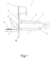
- FIG. 1 shows an embodiment according to the invention of a slicing device.
- the slicing device 5 has a knife 11 which cuts a food bar 2 into food slices 12.
- each food bar 2 is transported continuously or intermittently in the direction of the cutting plane 6 of the knife 11 by a conveyor 4, here two conveyor belts 4.
- the food slices generally fall onto a storage table 1 which is provided with transport means on which they are each configured to form a portion 14, here a stack.
- These portions 14 are then transported away from the cutting knife area and then packaged.
- the person skilled in the art recognizes that several food bars can be sliced at the same time. The slice thickness results from the feed distance of the food bar between two cuts.
- the slicing device can have a gripper (not shown) for each advancing route, which gripper grips the rear end 13 of the food bar 2 before or during the slicing and stabilizes it during the slicing.
- a means 3, here at least one projection is provided on the cutting knife, which corotates with the cutting knife 11 at the same speed and thereby generates a gas, in particular air flow, which stabilizes the at least partially, in particular completely cut off food slice in a desired shape and / or shapes.
- the gas, in particular air flow preferably flows along the side of the food slice facing the food bar, in particular between the food slice and the cutting knife.
- the gas, in particular air, flow can be pulsed and / or continuous.
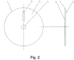
- Figure 2 shows a first embodiment of the cutting knife 11 according to the invention, here a circular knife.
- This has a cutting edge 7 with which the food slice 12 is separated from the food bar 2.
- the circular knife rotates both around its central axis 15 and around an orbital axis (not shown) during cutting, the speed of the cutting knife 11 around its central axis 15 preferably being a multiple of its speed around the orbital axis.
- the cutting knife has a means 3 with which a gas, in particular air flow is generated during its rotation, in particular about its central axis 15. This preferably pulsed and / or continuous air flow forms and / or stabilizes each at least partially cut food slice, in particular during its flight onto the storage table.
- the cut-off slice of food can, for example, be kept in a substantially planar shape by the air flow, which is advantageous, for example, for a stacked or shingled portion.
- the gas in particular air
- the means is a projection which is arranged on the side of the cutting knife facing away from the food bar.
- the means 3 can be a sheet metal part which is fastened to the cutting knife 11, for example by welding, gluing and / or by means of screws, rivets or the like.
- the means 3 is preferably in one piece with the cutting knife provided and can be made from the material of the cutting knife, for example by reshaping, for example a bulge or a material accumulation.
- the one-piece embodiment of the cutting knife according to the invention has proven to be particularly hygienic.
Landscapes
- Life Sciences & Earth Sciences (AREA)
- Forests & Forestry (AREA)
- Engineering & Computer Science (AREA)
- Mechanical Engineering (AREA)
- Food-Manufacturing Devices (AREA)
- Details Of Cutting Devices (AREA)
- Nonmetal Cutting Devices (AREA)
- Knives (AREA)
Description
- Die vorliegende Erfindung betrifft ein rotierendes Schneidmesser, das von einem Lebensmittelriegel eine Vielzahl von Lebensmittelscheiben abschneidet, wobei das Schneidmesser an einer Messeraufnahme vorgesehen ist. Des Weiteren betrifft die vorliegende Erfindung eine Aufschneidevorrichtung aufweisend das erfindungsgemäße Schneidmesser und ein Verfahren zum Aufschneiden eines Lebensmittelriegels, bei dem ein rotierendes Schneidmesser eine Vielzahl von Lebensmittelscheiben von einem Lebensmittelriegel abtrennt sowie ein Verfahren zum Aufschneiden eines Lebensmittelriegels, bei dem ein rotierendes Schneidmesser, das an einer Messeraufnahme angeordnet ist, eine Vielzahl von Lebensmittelscheiben von einem Lebensmittelriegel abtrennt und zwischen zwei Lebensmittelscheiben ein Interleaver angeordnet wird.
- Derartige Schneidmesser, Vorrichtungen sowie Verfahren sind aus dem Stand der Technik, beispielsweise der
DE 38 18 474 A1 und derUS 5 136 908 A , hinlänglich bekannt und werden dazu eingesetzt, Lebensmittelscheiben von einem Lebensmittelriegel, beispielsweise einem Wurst-, Käse- oder Schinkenriegel abzutrennen. Meistens fallen die Lebensmittelscheiben nach dem Abschneiden eine gewisse Wegstrecke auf eine Auflage, beispielsweise einen Ablagetisch, und/oder auf bereits abgeschnittene Lebensmittelscheiben. Dort werden sie zu einer Portion konfiguriert und dann abtransportiert. Insbesondere bei großen Lebensmittelscheiben kommt es bei dieser Fallbewegung und/oder bereits beim Abschneiden der jeweiligen Lebensmittelscheibe von dem Lebensmittelriegel zu einer unerwünschten Verformung, beispielsweise zum Falten oder Wellen, der jeweiligen Lebensmittelscheibe. Alternativ kann es aber auch wünschenswert sein die zunächst im Wesentlichen plane Lebensmittelscheibe in eine dreidimensionale Form zu bringen, beispielsweise zu falten. - Es war deshalb die Aufgabe der vorliegenden Erfindung ein Schneidmesser zur Verfügung zu stellen, mit dem eine Lebensmittelscheibe während des Abschneidens und/oder während ihres Fluges in einer gewünschten Form stabilisiert und/oder geformt wird.
- Gelöst wird die Aufgabe mit einem rotierenden Schneidmesser gemäß Patentanspruch 1.
- Die zu diesem Gegenstand der vorliegenden Erfindung gemachten Ausführungen gelten für die anderen Gegenstände der vorliegenden Erfindung gleichermaßen und umgekehrt.
- Die vorliegende Erfindung betrifft ein rotierendes Schneidmesser, das von einem Lebensmittel eine Vielzahl von Lebensmittelscheiben abschneidet. Bei einem derartigen Schneidmesser kann es sich beispielsweise um einen Kreismesser, ein Sichelmesser oder um ein Spiralmesser handeln. Vorzugsweise ist das Messer ein Kreismesser, das sich auf einer Orbitalbahn bewegt und sich beim Abschneiden einer Lebensmittelscheibe mehrfach um seine eigene Mittenachse dreht. Das Messer ist in der Regel an einer Messeraufnahme, die Teil eines Rotors einer Aufschneidevorrichtung ist, angeordnet. Bei solchen Aufschneidevorrichtungen wird ein Lebensmittelriegel entlang einer Vorschubtrasse kontinuierlich oder intermittierend in Richtung des Schneidmessers transportiert. Dieses Schneidmesser trennt von dem vorderen Ende des Lebensmittelriegels Lebensmittelscheiben ab. Die Dicke einer Lebensmittelscheibe wird durch den Vorschub, um den der Lebensmittelriegel weiter transportiert wird, während sich das Schneidmesser nicht im schneidenden Eingriff mit dem Lebensmittelriegel befindet, bestimmt. Nach dem Abschneiden fallen die Lebensmittelscheiben, insbesondere entlang einer Flugkurve, auf einen Ablagetisch und/oder auf eine bereits abgeschnittene Lebensmittelscheibe, wo sie zu einer Portion konfiguriert und dann abtransportiert werden.
- Erfindungsgemäß ist nun das Schneidmesser so gestaltet, dass eine Gas-, insbesondere Luftströmung erzeugt wird, die jede Lebensmittelscheibe während des Schneidens und/oder danach, d.h. während sie auf den Ablagetisch und/oder auf dort bereits vorhandene Lebensmittelscheiben fällt, formt und in einer gewünschten Form zumindest teilweise und/oder zeitweise stabilisiert. Der Gas-, insbesondere Luftstrom strömt dabei entlang dem bereits abgeschnittenen Teil der Lebensmittelscheibe und/oder entlang der vollständig abgeschnitten, sich vorzugsweise im Flug befindlichen Lebensmittelscheibe und formt und stabilisiert diese. Durch das Mittel kann ein pulsierender oder ein kontinuierlicher Gas-, insbesondere Luftstrom, erzeugt werden. Der Luftstrom kann einen Impuls auf die Lebensmittelschreibe ausüben und/oder einen Unterdruck auf einer Seite der Lebensmittelscheibe erzeugen, wodurch die Lebensmittelscheibe geformt und in ihrer gewünschten Form stabilisiert wird. Der Luftstrom kann auch dazu eingesetzt werden das Schneidmesser bei seiner Rotation zu stabilisieren so dass es beispielsweise weniger schwingt.
- Alternativ oder zusätzlich wird der von dem Mittel erzeugte Gas-, insbesondere Luftstrom, dazu eingesetzt ein Interleaver an jeweils eine abgeschnittene Lebensmittelscheibe anzulegen. Ein Interleaver ist ein Stück aus Papier oder einer papierähnlichen Substanz, das zwischen zwei Lebensmittelscheiben angeordnet wird, um deren Haftung zu vermindern.
- Das Mittel zur Erzeugung des Gas-, insbesondere Luftstroms kann aus einem beliebigen Werkstoff hergestellt werden, wobei es vorzugsweise aus Metall, insbesondere aus Stahl gefertigt ist.
- Erfindungsgemäß ist das Mittel ein Vorsprung, der auf der dem Lebensmittelriegel abgewandten Seite des Schneidmessers vorgesehen ist. Beispielsweise kann es sich bei dem Mittel um ein Blechteil handeln, das an dem Schreibmesser, beispielweise stoffschlüssig, insbesondere durch Schweißen oder Kleben und/oder kraft- und/oder formschlüssig, beispielsweise mittels Schrauben, Nieten oder dergleichen, befestigt wird. Besonders bevorzugt sind das Schneidmesser und das Mittel einstückig vorgesehen. Vorzugsweise wird das Mittel durch eine lokale Materialanhäufung oder durch Umformen des Materials, aus dem das Schneidmesser gefertigt ist, erzeugt. Insbesondere handelt es sich bei dem Mittel um eine Ausbuchtung, die in der Oberfläche des Schneidmessers vorgesehen wird.
- Ein weiterer Gegenstand der vorliegenden Erfindung ist eine Aufschneidevorrichtung, an der das erfindungsgemäße Schneidmesser angeordnet ist.
- Die zu diesem Gegenstand der vorliegenden Erfindung gemachten Ausführungen gelten für die anderen Gegenstände der vorliegenden Erfindung gleichermaßen und umgekehrt.
- Noch ein Gegenstand der vorliegenden Erfindung ist ein Verfahren zum Aufschneiden eines oder mehrerer Lebensmittelriegel, bei dem ein rotierendes Schneidmesser, das an einer Messeraufnahme angeordnet ist, eine Vielzahl von Lebensmittelscheiben von einem oder mehrerer Lebensmittelriegel abtrennt, wobei zwischen zwei Lebensmittelscheiben ein Interleaver angeordnet wird, bei dem der Interleaver durch einen von einem an dem Schneidmesser und/oder der Messeraufnahme angeordneten Mittel erzeugten Luftstrom an eine Lebensmittelscheibe angelegt wird.
- Die zu diesem Gegenstand der vorliegenden Erfindung gemachten Ausführungen gelten für die anderen Gegenstände der vorliegenden Erfindung gleichermaßen und umgekehrt.
- Vorzugsweise wird mittels des/der Gas- insbesondere Luftstrom/ströme, mindestens ein zusätzlicher Stoff auf die Messer- und/oder Produktoberfläche, beispielsweise ein Desinfektions-/Reinigungsmittel oder ein Austauschgas aufgebracht.
- Im Folgenden wird die Erfindung anhand der
Figuren 1 - 2 erläutert. Diese Erläuterungen sind lediglich beispielhaft und schränken den allgemeinen Erfindungsgedanken nicht ein. Die Erläuterungen gelten für alle Gegenstände der vorliegenden Erfindung gleichermaßen. - Figur 1
- zeigt die erfindungsgemäße Aufschneidevorrichtung.
- Figuren 2
- zeigt eine Ausführungsform des erfindungsgemäßen Schneidmessers.
-
Figur 1 zeigt eine erfindungsgemäße Ausführungsform einer Aufschneidevorrichtung. Die Aufschneidevorrichtung 5 weist ein Messer 11 auf, das einen Lebensmittelriegel 2 in Lebensmittelscheiben 12 schneidet. Dazu wird jeder Lebensmittelriegel 2 mit einem Fördermittel 4, hier zwei Förderbändern 4, kontinuierlich oder intermittierend in Richtung der Schneidebene 6 des Messers 11 transportiert. Nach dem Abschneiden fallen die Lebensmittelscheiben in der Regel auf einen Ablagetisch 1, der mit Transportmitteln versehen ist, auf dem sie zu jeweils einer Portion 14, hier einem Stapel, konfiguriert werden. Diese Portionen 14 werden sodann aus dem Schneidmesserbereich abtransportiert und danach verpackt. Der Fachmann erkennt, dass mehrere Lebensmittelriegel gleichzeitig aufgeschnitten werden können. Die Scheibenstärke ergibt sich aus der Vorschubstrecke des Lebensmittelriegels zwischen zwei Schnitten. Bei konstanter Messerdrehgeschwindigkeit erfolgt die Regelung der Scheibenstärke über die Vorschubgeschwindigkeit des Lebensmittelriegels. Die Aufschneidevorrichtung kann pro Vorschubtrasse einen Greifer (nicht dargestellt) aufweisen, der das rückwärtige Ende 13 des Lebensmittelriegels 2 vor oder während des Aufschneidens ergreift und diesen während des Aufschneidens stabilisiert.
Erfindungsgemäß ist an dem Schneidmesser ein Mittel 3, hier mindestens ein Vorsprung, vorgesehen, das mit dem Schneidmesser 11 mit derselben Drehzahl korotiert und dabei einen Gas-, insbesondere Luftstrom, erzeugt, der die zumindest teilweise, insbesondere vollständig abgeschnittene Lebensmittelscheibe in einer gewünschten Form stabilisiert und/oder formt. Der Gas-, insbesondere Luftstrom, strömt dazu vorzugsweise entlang der dem Lebensmittelriegel zugewandten Seite der Lebensmittelscheibe entlang, insbesondere zwischen der Lebensmittelscheibe und dem Schneidmesser. Der Gas-, insbesondere Luftstrom kann impulsartig und/oder kontinuierlich sein. -
Figur 2 zeigt eine erste Ausführungsform des erfindungsgemäßen Schneidmessers 11 hier eines Kreismessers. Dieses weist eine Schneidkante 7 auf, mit der die Lebensmittelscheibe 12 von dem Lebensmittelriegel 2 abgetrennt wird. Das Kreismesser dreht sich während des Schneidens sowohl um seine Mittelachse 15 als auch um eine Orbitalachse (nicht dargestellt), wobei die Drehzahl des Schneidmessers 11 um seine Mittelachse 15 vorzugsweise ein Vielfaches seiner Drehzahl um die Orbitalachse beträgt. Erfindungsgemäß weist das Schneidmesser ein Mittel 3 auf, mit dem während seiner Drehung, insbesondere um seine Mittelachse 15 ein Gas-, insbesondere Luftstrom, erzeugt wird. Dieser vorzugsweise impulsartige und/oder kontinuierliche Luftstrom formt und/oder stabilisiert jede zumindest teilweise abgeschnittene Lebensmittelscheibe, insbesondere während ihres Fluges auf den Ablagetisch. Durch den Luftstrom kann die abgeschnittene Lebensmittelscheibe beispielsweise in einer im Wesentlichen planen Form gehalten werden, was beispielsweise für eine gestapelte oder geschindelte Portion von Vorteil ist. Mit dem Gas-, insbesondere Luftstrom, ist es jedoch auch möglich die Lebensmittelscheibe, insbesondere während ihres Fluges auf den Ablagetisch, zu formen beispielsweise zu falten und/oder zu wellen. In dem vorliegenden Fall ist das Mittel ein Vorsprung, der auf der dem Lebensmittelriegel abgewandten Seite des Schneidmessers angeordnet ist. Bei dem Mittel 3 kann es sich um ein Blechteil handeln, das beispielsweise durch Schweißen, Kleben und/oder mittels Schrauben, Nieten oder dergleichen an dem Schneidmesser 11 befestigt wird. Vorzugsweise ist das Mittel 3 jedoch einstückig mit dem Schneidmesser vorgesehen und kann beispielsweise durch Umformen, beispielsweise eine Ausbuchtung oder eine Materialanhäufung, aus dem Material des Schneidmessers gefertigt werden. Die einstückige Ausführungsform des erfindungsgemäßen Schneidmessers hat sich als besonders hygienisch herausgestellt. -
- 1
- Ablagetisch
- 2
- Lebensmittelriegel
- 3
- Mittel zur Erzeugung einer Gas- insbesondere Luftströmung
- 4
- Transportmittel
- 5
- Aufschneidevorrichtung
- 6
- Schneidebene
- 7
- Schneidkante des Schneidmessers 11
- 8
- Rotor, Messeraufnahme
- 9
- Abdeckung
- 10
- Gas-, insbesondere Luftstrom
- 11
- Messer, Kreismesser
- 12
- Lebensmittelscheiben
- 13
- rückwärtiges Ende
- 14
- Portion
- 15
- Mittelachse des Schneidmessers
Claims (8)
- Rotierendes Schneidmesser (11), das von einem oder mehreren Lebensmittelriegeln (2) eine Vielzahl von Lebensmittelscheiben (12) abschneidet, wobei das Schneidmesser an einer Messeraufnahme (8) vorgesehen ist, wobei an dem Schneidmesser mindestens ein Mittel (3) vorgesehen ist und/oder dass ein Schneidmesser entsprechend so gestaltet ist, dass eine oder mehrere Gasinsbesondere Luftströmungen erzeugt werden, die jede Lebensmittelscheibe während des Schneidens und/oder danach formen und in einer gewünschten Form zumindest teilweise und/oder zeitweise stabilisieren und/oder die einen Interleaver an eine Lebensmittelscheibe anlegen, dadurch gekennzeichnet, dass das Mittel (3) mindestens ein Vorsprung ist, der auf der dem Lebensmittelriegel abgewandten Seite des Schneidmessers angeordnet ist, wobei das Mittel mindestens eine Schaufel (13) ist, die den Luftstrom erzeugt.
- Rotierendes Schneidmesser (11) nach Anspruch 1, dadurch gekennzeichnet, dass das Schneidmesser und das Mittel (3) einstückig vorgesehen sind.
- Rotierendes Schneidmesser (11) nach einem der voranstehenden Ansprüche, dadurch gekennzeichnet, dass die Schaufel (13) in ihrer Ausrichtung relativ zum Schneidmesser veränderbar ist.
- Rotierendes Schneidmesser (11) nach einem der voranstehenden Ansprüche, dadurch gekennzeichnet, dass das Mittel mit derselben Drehzahl rotiert wie das Schneidmesser.
- Rotierendes Schneidmesser (11) nach einem der voranstehenden Ansprüche, dadurch gekennzeichnet, dass das Mittel in gleicher Drehrichtung rotiert wie das Schneidmesser.
- Rotierendes Schneidmesser (11) nach einem der voranstehenden Ansprüche, dadurch gekennzeichnet, dass das Schneidmesser ein Kreismesser ist, das auf einer Orbitalbahn umläuft.
- Aufschneidevorrichtung aufweisend ein Schneidmesser gemäß einem der voranstehenden Ansprüche.
- Verfahren zum Aufschneiden eines oder mehrerer Lebensmittelriegel, bei dem ein rotierendes Schneidmesser (11), das an einer Messeraufnahme (8) angeordnet ist, eine Vielzahl von Lebensmittelscheiben (12) von einem oder mehrerer Lebensmittelriegel (11) abtrennt, wobei zwischen zwei Lebensmittelscheiben ein Interleaver angeordnet wird, dadurch gekennzeichnet, dass der Interleaver durch einen von einem an dem Schneidmesser und/oder der Messeraufnahme angeordneten Mittel erzeugten Luftstrom an eine Lebensmittelscheibe angelegt wird.
Applications Claiming Priority (2)
| Application Number | Priority Date | Filing Date | Title |
|---|---|---|---|
| DE201210004960 DE102012004960A1 (de) | 2012-03-14 | 2012-03-14 | Schneidmesser mit einem Mittel zur Erzeugung eines Luftstroms |
| PCT/EP2013/055289 WO2013135843A2 (de) | 2012-03-14 | 2013-03-14 | Schneidmesser mit einem mittel zur erzeugung eines luftstroms |
Publications (3)
| Publication Number | Publication Date |
|---|---|
| EP2825354A2 EP2825354A2 (de) | 2015-01-21 |
| EP2825354B1 EP2825354B1 (de) | 2017-09-06 |
| EP2825354B2 true EP2825354B2 (de) | 2020-12-02 |
Family
ID=47891709
Family Applications (1)
| Application Number | Title | Priority Date | Filing Date |
|---|---|---|---|
| EP13709899.2A Active EP2825354B2 (de) | 2012-03-14 | 2013-03-14 | Schneidmesser mit einem mittel zur erzeugung eines luftstroms |
Country Status (5)
| Country | Link |
|---|---|
| US (1) | US20150047482A1 (de) |
| EP (1) | EP2825354B2 (de) |
| DE (1) | DE102012004960A1 (de) |
| ES (1) | ES2650389T5 (de) |
| WO (1) | WO2013135843A2 (de) |
Families Citing this family (7)
| Publication number | Priority date | Publication date | Assignee | Title |
|---|---|---|---|---|
| DE102012112103A1 (de) * | 2012-12-11 | 2014-06-12 | Gea Food Solutions Germany Gmbh | Aufschneidevorrichtung mit einer Faltleiste |
| DE102013007275A1 (de) * | 2013-04-26 | 2014-11-13 | Weber Maschinenbau Gmbh Breidenbach | Lebensmittelaufschneidemesser mit einem Funktransponder |
| DE102014118164A1 (de) * | 2014-12-08 | 2016-06-09 | Weber Maschinenbau Gmbh Breidenbach | Schneidmesser |
| EP3380419B1 (de) * | 2015-11-23 | 2020-01-01 | GEA Food Solutions Germany GmbH | Verfahren und vorrichtung zum portionieren von lebensmittelscheiben mit formveränderung, insbesondere faltung, der portion |
| US11073447B2 (en) * | 2016-03-31 | 2021-07-27 | Agilent Technologies, Inc. | Apparatus and methods for transferring a tissue section |
| DK3495104T3 (da) * | 2017-12-05 | 2020-09-28 | Marel Meat Bv | Et fødevareseparatorapparat |
| DE102020112863A1 (de) * | 2020-05-12 | 2021-11-18 | Tvi Entwicklung Und Produktion Gmbh | Gewichts-Variations-Verfahren sowie Aufschneidemaschine zu seinem Betrieb |
Citations (7)
| Publication number | Priority date | Publication date | Assignee | Title |
|---|---|---|---|---|
| DE3818474A1 (de) † | 1988-05-31 | 1989-12-21 | Holac Maschbau Gmbh | Verfahren und vorrichtung zum schneiden von lebensmitteln |
| JPH06320493A (ja) † | 1993-05-14 | 1994-11-22 | Nanjo Tekko Kk | 縦型食肉スライサー |
| DE19926461A1 (de) † | 1999-06-10 | 2000-12-14 | Biforce Anstalt Vaduz | Vorrichtung zum Aufschneiden von Lebensmittelprodukten |
| DE10057333A1 (de) † | 2000-11-17 | 2002-05-23 | Cfs Gmbh Kempten | Vorrichtung an Schneidmaschinen |
| EP2082854A1 (de) † | 2008-01-28 | 2009-07-29 | Arelmasani Holding B.V. | Trennvorrichtung für Lebensmittelprodukte |
| WO2010086006A1 (de) † | 2009-01-30 | 2010-08-05 | Weber Maschinenbau Gmbh Breidenbach | Rotierendes schneidmesser für lebensmittel |
| WO2013152842A1 (de) † | 2012-04-11 | 2013-10-17 | Weber Maschinenbau Gmbh Breidenbach | Schneidmesser |
Family Cites Families (44)
| Publication number | Priority date | Publication date | Assignee | Title |
|---|---|---|---|---|
| US1878071A (en) * | 1926-09-08 | 1932-09-20 | Mij Exploitatie Octrooien Nv | Slice deflector |
| DE470132C (de) * | 1926-09-08 | 1929-01-05 | Berkel Patent Nv | Scheibenablenkvorrichtung fuer Aufschnittschneidemaschinen |
| US1974602A (en) * | 1931-08-03 | 1934-09-25 | Ind Patents Corp | Slicing machine |
| US1957623A (en) | 1931-11-21 | 1934-05-08 | Ind Patents Corp | Slicing machine |
| US3282263A (en) * | 1963-07-29 | 1966-11-01 | Christensen Diamond Prod Co | Face discharge cutting blades |
| US3754359A (en) * | 1970-09-16 | 1973-08-28 | Spam D Avray | Abrasion tools |
| US3727504A (en) * | 1971-08-05 | 1973-04-17 | A Osterholt | Meat slicing knife |
| US3932967A (en) * | 1975-05-07 | 1976-01-20 | Hanes Donald M | Sharpener for rotary electric razor |
| DE2623339C2 (de) * | 1976-05-25 | 1982-02-25 | Ernst Prof. Dr.-Ing. 2106 Bendestorf Salje | Kreissägeblatt |
| DE2842105A1 (de) | 1978-09-27 | 1980-04-10 | Kober Kg A | Rotations-schneidmesser mit wellenfoermig ausgebildeten, einen ziehenden schnitt ermoeglichenden schneidkanten |
| US4282910A (en) * | 1980-07-10 | 1981-08-11 | Michigan Technological University | Fingerling shear |
| DE3239178A1 (de) * | 1982-10-22 | 1984-04-26 | Natec Reich, Summer GmbH & Co KG, 8999 Heimenkirch | Maschine zum schneiden von schneidgutriegeln |
| US4712458A (en) * | 1986-12-11 | 1987-12-15 | Oscar Mayer Foods Corporation | Food loaf slicing machine with improved stacking characteristics |
| US4776251A (en) * | 1987-06-12 | 1988-10-11 | Pacific Saw And Knife Company | Circular saw blade with circumferentally extending laser-cut slots |
| DE3742864A1 (de) | 1987-12-17 | 1989-07-27 | Kurt Horn | Messer mit konstanter schneidenschaerfe |
| DE3911803A1 (de) * | 1989-04-11 | 1990-10-31 | Walter Arndt | Vorrichtung zur kuehlung von kreismessern in papierschneidmaschinen |
| US5078035A (en) * | 1989-08-21 | 1992-01-07 | Diamond Products, Inc. | Circular saw blade |
| DE4031671C2 (de) | 1990-10-05 | 1994-02-24 | Natec Reich Summer Gmbh Co Kg | Kreismesser zum Schneiden von Lebensmitteln, insbesondere Wurst und Käse |
| US5136908A (en) * | 1991-07-29 | 1992-08-11 | Valley Slicer Co. | Food slicer apparatus and knife therefor |
| JP3327482B2 (ja) * | 1993-02-25 | 2002-09-24 | ワタナベフーマック株式会社 | 食品スライサにおける切片の折り曲げ装置 |
| DE4402923A1 (de) * | 1994-02-01 | 1995-08-03 | Dixie Union Verpackungen Gmbh | Vorrichtung zum Einlegen von Papierzetteln in Aufschnittportionen |
| DE69618671T2 (de) * | 1995-10-12 | 2002-08-29 | Gebelius, Hjoerdis Florence Maria | VERFAHREN ZUM VERMEIDEN ODER REDUZIEREN DER FORMUNG VON MAGNETISMUS ZWISCHEN ZWEI BENACHBARTEN GEGENSINNIG DREHENDEN KREISSäGEBLäTTER UND VORRICHTUNG ZUR DURCHFüHRUNG DES VERFAHRENS |
| DE19739788A1 (de) | 1997-09-10 | 1999-03-11 | Alpma Alpenland Masch | Schneidmesser |
| US6173499B1 (en) * | 1998-12-08 | 2001-01-16 | Gary M. Hegoas | Vent cover for an electric saw |
| DE29901713U1 (de) * | 1999-02-01 | 2000-06-29 | Powertools International GmbH, 25474 Ellerbek | Sägeblatt |
| KR100319131B1 (ko) * | 1999-06-14 | 2001-12-29 | 정운조 | 식품 슬라이서의 절단편 이탈 안내장치 |
| JP3874990B2 (ja) * | 2000-04-18 | 2007-01-31 | 株式会社マキタ | 切断機の照明装置 |
| DE20009726U1 (de) * | 2000-05-30 | 2000-08-24 | System GmbH, 40549 Düsseldorf | Rotationsschneider mit luftgekühlten Messerköpfen |
| USD463965S1 (en) * | 2001-02-15 | 2002-10-08 | Ehwa Diamond Ind. Co., Ltd. | Grinding wheel |
| KR100440869B1 (ko) * | 2001-02-19 | 2004-07-19 | 이화다이아몬드공업 주식회사 | 절단용 톱판 |
| AT411584B (de) * | 2002-07-12 | 2004-03-25 | Kuchler Fritz | Aufschnittschneidemaschine |
| DE102004007671A1 (de) * | 2004-02-13 | 2005-09-22 | Cfs Kempten Gmbh | Verfahren und Vorrichtung zur Erzeugung von Portionen |
| DE102005003040B4 (de) | 2004-08-19 | 2008-06-12 | Astor Schneidwerkzeuge Gmbh | Lebensmittelschneidemaschine mit einem umlaufenden Kreismesser |
| US20060090429A1 (en) * | 2004-11-01 | 2006-05-04 | Wall Jere J | Spinner top for an air filter |
| WO2007050677A2 (en) * | 2005-10-25 | 2007-05-03 | Formax, Inc. | Sheet interleaver for slicing apparatus |
| SE531916C2 (sv) * | 2008-01-24 | 2009-09-08 | Haellde Maskiner Ab | Skärskiva |
| CA2742696C (en) * | 2008-11-05 | 2016-12-13 | Spraying Systems Co. | Pathogen reduction system for the preparation of sliced food products |
| DE102009011399A1 (de) * | 2009-03-03 | 2010-09-09 | Weber Maschinenbau Gmbh Breidenbach | Schneidvorrichtung |
| DE102009011398A1 (de) * | 2009-03-03 | 2010-09-09 | Weber Maschinenbau Gmbh Breidenbach | Schneidvorrichtung |
| DE102009030550A1 (de) | 2009-06-25 | 2010-12-30 | Weber Maschinenbau Gmbh Breidenbach | Schneidmesser |
| DE102009032974A1 (de) | 2009-07-14 | 2011-01-20 | Weber Maschinenbau Gmbh Breidenbach | Vorrichtung zum Aufschneiden von Lebensmittelprodukten |
| AU2009203210A1 (en) * | 2009-08-03 | 2011-02-17 | Frelk Industries Pty Ltd | Pipe cutting device |
| DE102010031393B4 (de) * | 2010-07-15 | 2012-07-05 | Albert Handtmann Maschinenfabrik Gmbh & Co. Kg | Vorrichtung und Verfahren zur Kühlung von Nahrungsmittelmaschinen |
| DE102012007290A1 (de) * | 2012-04-12 | 2013-10-17 | Weber Maschinenbau Gmbh Breidenbach | Schneidmesser mit Abweiselement |
-
2012
- 2012-03-14 DE DE201210004960 patent/DE102012004960A1/de not_active Withdrawn
-
2013
- 2013-03-14 WO PCT/EP2013/055289 patent/WO2013135843A2/de not_active Ceased
- 2013-03-14 EP EP13709899.2A patent/EP2825354B2/de active Active
- 2013-03-14 US US14/384,230 patent/US20150047482A1/en not_active Abandoned
- 2013-03-14 ES ES13709899T patent/ES2650389T5/es active Active
Patent Citations (7)
| Publication number | Priority date | Publication date | Assignee | Title |
|---|---|---|---|---|
| DE3818474A1 (de) † | 1988-05-31 | 1989-12-21 | Holac Maschbau Gmbh | Verfahren und vorrichtung zum schneiden von lebensmitteln |
| JPH06320493A (ja) † | 1993-05-14 | 1994-11-22 | Nanjo Tekko Kk | 縦型食肉スライサー |
| DE19926461A1 (de) † | 1999-06-10 | 2000-12-14 | Biforce Anstalt Vaduz | Vorrichtung zum Aufschneiden von Lebensmittelprodukten |
| DE10057333A1 (de) † | 2000-11-17 | 2002-05-23 | Cfs Gmbh Kempten | Vorrichtung an Schneidmaschinen |
| EP2082854A1 (de) † | 2008-01-28 | 2009-07-29 | Arelmasani Holding B.V. | Trennvorrichtung für Lebensmittelprodukte |
| WO2010086006A1 (de) † | 2009-01-30 | 2010-08-05 | Weber Maschinenbau Gmbh Breidenbach | Rotierendes schneidmesser für lebensmittel |
| WO2013152842A1 (de) † | 2012-04-11 | 2013-10-17 | Weber Maschinenbau Gmbh Breidenbach | Schneidmesser |
Also Published As
| Publication number | Publication date |
|---|---|
| DE102012004960A1 (de) | 2013-09-19 |
| ES2650389T5 (es) | 2021-09-14 |
| EP2825354B1 (de) | 2017-09-06 |
| US20150047482A1 (en) | 2015-02-19 |
| EP2825354A2 (de) | 2015-01-21 |
| WO2013135843A2 (de) | 2013-09-19 |
| ES2650389T3 (es) | 2018-01-18 |
| WO2013135843A3 (de) | 2014-01-16 |
Similar Documents
| Publication | Publication Date | Title |
|---|---|---|
| EP2825354B2 (de) | Schneidmesser mit einem mittel zur erzeugung eines luftstroms | |
| WO2015154871A1 (de) | Aufschneidevorrichtung mit rapid-manufacturing-teilen | |
| EP1680263B1 (de) | Verfahren und vorrichtung zum aufschneiden von lebensmittelriegeln | |
| DE102014119707B3 (de) | Querschneiden eines bewegten Lebensmittelproduktes | |
| EP2900440B1 (de) | Vorrichtung und verfahren zum kontinuierlichen aufschneiden von lebensmittelprodukten | |
| EP3204201A1 (de) | Geteilte lebensmittelportionen | |
| EP3105020B1 (de) | Aufschneidevorrichtung mit einem zufuhrkanal für zwischenlegepapier | |
| WO2010066897A2 (de) | Schneiden von stücken aus einer käsemasse | |
| EP1995026B1 (de) | Verfahren zum Aufschneiden von Lebensmittelriegeln | |
| DE102012109003A1 (de) | Aufschnittschneidemaschine | |
| EP2884845B1 (de) | Anlage zum herstellen von endprodukten durch das zerschneiden von flach- und hohlwaffelblöcken | |
| SE442719B (sv) | Koksredskap for att skera strimlor av livsmedel | |
| EP2894016A1 (de) | Vorrichtung und Verfahren zum Aufschneiden von Lebensmittelprodukten | |
| EP3484774B1 (de) | Vorrichtung zum verschliessen von versandverpackungen | |
| EP2522472A1 (de) | Perforationseinheit einer Verpackungsmaschine | |
| EP3380419B1 (de) | Verfahren und vorrichtung zum portionieren von lebensmittelscheiben mit formveränderung, insbesondere faltung, der portion | |
| EP3500410B2 (de) | Verfahren zum aufschneiden von gewichtsgenauen portionen | |
| EP1885529A1 (de) | Greifer mit anlageflächen | |
| WO2014090637A1 (de) | Aufschneidevorrichtung mit einer faltleiste | |
| DE102014205173A1 (de) | Wickelvorrichtung | |
| DE102013218263A1 (de) | Schneidleiste mit einem integrierten Verschleißteil | |
| EP3377282B1 (de) | Verfahren zur unabhängigen portionsbildung aus lebensmittelscheiben in mehreren spuren | |
| EP2065145B1 (de) | Verwendung einer Vorrichtung zum Raspeln von Käse | |
| EP3062976B1 (de) | Slicer mit messer aus kunststoff | |
| DE102012025599A1 (de) | Messer |
Legal Events
| Date | Code | Title | Description |
|---|---|---|---|
| PUAI | Public reference made under article 153(3) epc to a published international application that has entered the european phase |
Free format text: ORIGINAL CODE: 0009012 |
|
| 17P | Request for examination filed |
Effective date: 20140909 |
|
| AK | Designated contracting states |
Kind code of ref document: A2 Designated state(s): AL AT BE BG CH CY CZ DE DK EE ES FI FR GB GR HR HU IE IS IT LI LT LU LV MC MK MT NL NO PL PT RO RS SE SI SK SM TR |
|
| AX | Request for extension of the european patent |
Extension state: BA ME |
|
| DAX | Request for extension of the european patent (deleted) | ||
| 17Q | First examination report despatched |
Effective date: 20151127 |
|
| STAA | Information on the status of an ep patent application or granted ep patent |
Free format text: STATUS: EXAMINATION IS IN PROGRESS |
|
| GRAP | Despatch of communication of intention to grant a patent |
Free format text: ORIGINAL CODE: EPIDOSNIGR1 |
|
| STAA | Information on the status of an ep patent application or granted ep patent |
Free format text: STATUS: GRANT OF PATENT IS INTENDED |
|
| INTG | Intention to grant announced |
Effective date: 20170412 |
|
| GRAS | Grant fee paid |
Free format text: ORIGINAL CODE: EPIDOSNIGR3 |
|
| GRAA | (expected) grant |
Free format text: ORIGINAL CODE: 0009210 |
|
| STAA | Information on the status of an ep patent application or granted ep patent |
Free format text: STATUS: THE PATENT HAS BEEN GRANTED |
|
| AK | Designated contracting states |
Kind code of ref document: B1 Designated state(s): AL AT BE BG CH CY CZ DE DK EE ES FI FR GB GR HR HU IE IS IT LI LT LU LV MC MK MT NL NO PL PT RO RS SE SI SK SM TR |
|
| REG | Reference to a national code |
Ref country code: GB Ref legal event code: FG4D Free format text: NOT ENGLISH |
|
| REG | Reference to a national code |
Ref country code: CH Ref legal event code: EP Ref country code: AT Ref legal event code: REF Ref document number: 925369 Country of ref document: AT Kind code of ref document: T Effective date: 20170915 |
|
| REG | Reference to a national code |
Ref country code: IE Ref legal event code: FG4D Free format text: LANGUAGE OF EP DOCUMENT: GERMAN |
|
| REG | Reference to a national code |
Ref country code: DE Ref legal event code: R096 Ref document number: 502013008277 Country of ref document: DE |
|
| REG | Reference to a national code |
Ref country code: NL Ref legal event code: FP |
|
| REG | Reference to a national code |
Ref country code: ES Ref legal event code: FG2A Ref document number: 2650389 Country of ref document: ES Kind code of ref document: T3 Effective date: 20180118 |
|
| REG | Reference to a national code |
Ref country code: LT Ref legal event code: MG4D |
|
| PG25 | Lapsed in a contracting state [announced via postgrant information from national office to epo] |
Ref country code: SE Free format text: LAPSE BECAUSE OF FAILURE TO SUBMIT A TRANSLATION OF THE DESCRIPTION OR TO PAY THE FEE WITHIN THE PRESCRIBED TIME-LIMIT Effective date: 20170906 Ref country code: LT Free format text: LAPSE BECAUSE OF FAILURE TO SUBMIT A TRANSLATION OF THE DESCRIPTION OR TO PAY THE FEE WITHIN THE PRESCRIBED TIME-LIMIT Effective date: 20170906 Ref country code: NO Free format text: LAPSE BECAUSE OF FAILURE TO SUBMIT A TRANSLATION OF THE DESCRIPTION OR TO PAY THE FEE WITHIN THE PRESCRIBED TIME-LIMIT Effective date: 20171206 Ref country code: FI Free format text: LAPSE BECAUSE OF FAILURE TO SUBMIT A TRANSLATION OF THE DESCRIPTION OR TO PAY THE FEE WITHIN THE PRESCRIBED TIME-LIMIT Effective date: 20170906 Ref country code: HR Free format text: LAPSE BECAUSE OF FAILURE TO SUBMIT A TRANSLATION OF THE DESCRIPTION OR TO PAY THE FEE WITHIN THE PRESCRIBED TIME-LIMIT Effective date: 20170906 |
|
| PG25 | Lapsed in a contracting state [announced via postgrant information from national office to epo] |
Ref country code: RS Free format text: LAPSE BECAUSE OF FAILURE TO SUBMIT A TRANSLATION OF THE DESCRIPTION OR TO PAY THE FEE WITHIN THE PRESCRIBED TIME-LIMIT Effective date: 20170906 Ref country code: LV Free format text: LAPSE BECAUSE OF FAILURE TO SUBMIT A TRANSLATION OF THE DESCRIPTION OR TO PAY THE FEE WITHIN THE PRESCRIBED TIME-LIMIT Effective date: 20170906 Ref country code: GR Free format text: LAPSE BECAUSE OF FAILURE TO SUBMIT A TRANSLATION OF THE DESCRIPTION OR TO PAY THE FEE WITHIN THE PRESCRIBED TIME-LIMIT Effective date: 20171207 Ref country code: BG Free format text: LAPSE BECAUSE OF FAILURE TO SUBMIT A TRANSLATION OF THE DESCRIPTION OR TO PAY THE FEE WITHIN THE PRESCRIBED TIME-LIMIT Effective date: 20171206 |
|
| REG | Reference to a national code |
Ref country code: FR Ref legal event code: PLFP Year of fee payment: 6 |
|
| PG25 | Lapsed in a contracting state [announced via postgrant information from national office to epo] |
Ref country code: PL Free format text: LAPSE BECAUSE OF FAILURE TO SUBMIT A TRANSLATION OF THE DESCRIPTION OR TO PAY THE FEE WITHIN THE PRESCRIBED TIME-LIMIT Effective date: 20170906 Ref country code: CZ Free format text: LAPSE BECAUSE OF FAILURE TO SUBMIT A TRANSLATION OF THE DESCRIPTION OR TO PAY THE FEE WITHIN THE PRESCRIBED TIME-LIMIT Effective date: 20170906 Ref country code: RO Free format text: LAPSE BECAUSE OF FAILURE TO SUBMIT A TRANSLATION OF THE DESCRIPTION OR TO PAY THE FEE WITHIN THE PRESCRIBED TIME-LIMIT Effective date: 20170906 |
|
| REG | Reference to a national code |
Ref country code: DE Ref legal event code: R026 Ref document number: 502013008277 Country of ref document: DE |
|
| PG25 | Lapsed in a contracting state [announced via postgrant information from national office to epo] |
Ref country code: EE Free format text: LAPSE BECAUSE OF FAILURE TO SUBMIT A TRANSLATION OF THE DESCRIPTION OR TO PAY THE FEE WITHIN THE PRESCRIBED TIME-LIMIT Effective date: 20170906 Ref country code: IS Free format text: LAPSE BECAUSE OF FAILURE TO SUBMIT A TRANSLATION OF THE DESCRIPTION OR TO PAY THE FEE WITHIN THE PRESCRIBED TIME-LIMIT Effective date: 20180106 Ref country code: SK Free format text: LAPSE BECAUSE OF FAILURE TO SUBMIT A TRANSLATION OF THE DESCRIPTION OR TO PAY THE FEE WITHIN THE PRESCRIBED TIME-LIMIT Effective date: 20170906 Ref country code: SM Free format text: LAPSE BECAUSE OF FAILURE TO SUBMIT A TRANSLATION OF THE DESCRIPTION OR TO PAY THE FEE WITHIN THE PRESCRIBED TIME-LIMIT Effective date: 20170906 |
|
| PLBI | Opposition filed |
Free format text: ORIGINAL CODE: 0009260 |
|
| PLAX | Notice of opposition and request to file observation + time limit sent |
Free format text: ORIGINAL CODE: EPIDOSNOBS2 |
|
| 26 | Opposition filed |
Opponent name: WEBER MASCHINENBAU GMBH BREIDENBACH Effective date: 20180530 |
|
| PG25 | Lapsed in a contracting state [announced via postgrant information from national office to epo] |
Ref country code: DK Free format text: LAPSE BECAUSE OF FAILURE TO SUBMIT A TRANSLATION OF THE DESCRIPTION OR TO PAY THE FEE WITHIN THE PRESCRIBED TIME-LIMIT Effective date: 20170906 |
|
| PG25 | Lapsed in a contracting state [announced via postgrant information from national office to epo] |
Ref country code: SI Free format text: LAPSE BECAUSE OF FAILURE TO SUBMIT A TRANSLATION OF THE DESCRIPTION OR TO PAY THE FEE WITHIN THE PRESCRIBED TIME-LIMIT Effective date: 20170906 |
|
| PG25 | Lapsed in a contracting state [announced via postgrant information from national office to epo] |
Ref country code: MT Free format text: LAPSE BECAUSE OF FAILURE TO SUBMIT A TRANSLATION OF THE DESCRIPTION OR TO PAY THE FEE WITHIN THE PRESCRIBED TIME-LIMIT Effective date: 20170906 |
|
| PLBB | Reply of patent proprietor to notice(s) of opposition received |
Free format text: ORIGINAL CODE: EPIDOSNOBS3 |
|
| REG | Reference to a national code |
Ref country code: CH Ref legal event code: PL |
|
| PG25 | Lapsed in a contracting state [announced via postgrant information from national office to epo] |
Ref country code: MC Free format text: LAPSE BECAUSE OF FAILURE TO SUBMIT A TRANSLATION OF THE DESCRIPTION OR TO PAY THE FEE WITHIN THE PRESCRIBED TIME-LIMIT Effective date: 20170906 |
|
| REG | Reference to a national code |
Ref country code: BE Ref legal event code: MM Effective date: 20180331 |
|
| REG | Reference to a national code |
Ref country code: IE Ref legal event code: MM4A |
|
| PG25 | Lapsed in a contracting state [announced via postgrant information from national office to epo] |
Ref country code: LU Free format text: LAPSE BECAUSE OF NON-PAYMENT OF DUE FEES Effective date: 20180314 |
|
| PG25 | Lapsed in a contracting state [announced via postgrant information from national office to epo] |
Ref country code: IE Free format text: LAPSE BECAUSE OF NON-PAYMENT OF DUE FEES Effective date: 20180314 |
|
| PG25 | Lapsed in a contracting state [announced via postgrant information from national office to epo] |
Ref country code: CH Free format text: LAPSE BECAUSE OF NON-PAYMENT OF DUE FEES Effective date: 20180331 Ref country code: LI Free format text: LAPSE BECAUSE OF NON-PAYMENT OF DUE FEES Effective date: 20180331 Ref country code: BE Free format text: LAPSE BECAUSE OF NON-PAYMENT OF DUE FEES Effective date: 20180331 |
|
| REG | Reference to a national code |
Ref country code: AT Ref legal event code: MM01 Ref document number: 925369 Country of ref document: AT Kind code of ref document: T Effective date: 20180314 |
|
| PG25 | Lapsed in a contracting state [announced via postgrant information from national office to epo] |
Ref country code: AT Free format text: LAPSE BECAUSE OF NON-PAYMENT OF DUE FEES Effective date: 20180314 |
|
| PG25 | Lapsed in a contracting state [announced via postgrant information from national office to epo] |
Ref country code: TR Free format text: LAPSE BECAUSE OF FAILURE TO SUBMIT A TRANSLATION OF THE DESCRIPTION OR TO PAY THE FEE WITHIN THE PRESCRIBED TIME-LIMIT Effective date: 20170906 |
|
| PG25 | Lapsed in a contracting state [announced via postgrant information from national office to epo] |
Ref country code: PT Free format text: LAPSE BECAUSE OF FAILURE TO SUBMIT A TRANSLATION OF THE DESCRIPTION OR TO PAY THE FEE WITHIN THE PRESCRIBED TIME-LIMIT Effective date: 20170906 Ref country code: HU Free format text: LAPSE BECAUSE OF FAILURE TO SUBMIT A TRANSLATION OF THE DESCRIPTION OR TO PAY THE FEE WITHIN THE PRESCRIBED TIME-LIMIT; INVALID AB INITIO Effective date: 20130314 |
|
| PG25 | Lapsed in a contracting state [announced via postgrant information from national office to epo] |
Ref country code: CY Free format text: LAPSE BECAUSE OF FAILURE TO SUBMIT A TRANSLATION OF THE DESCRIPTION OR TO PAY THE FEE WITHIN THE PRESCRIBED TIME-LIMIT Effective date: 20170906 Ref country code: MK Free format text: LAPSE BECAUSE OF NON-PAYMENT OF DUE FEES Effective date: 20170906 |
|
| PG25 | Lapsed in a contracting state [announced via postgrant information from national office to epo] |
Ref country code: AL Free format text: LAPSE BECAUSE OF FAILURE TO SUBMIT A TRANSLATION OF THE DESCRIPTION OR TO PAY THE FEE WITHIN THE PRESCRIBED TIME-LIMIT Effective date: 20170906 |
|
| PUAH | Patent maintained in amended form |
Free format text: ORIGINAL CODE: 0009272 |
|
| STAA | Information on the status of an ep patent application or granted ep patent |
Free format text: STATUS: PATENT MAINTAINED AS AMENDED |
|
| 27A | Patent maintained in amended form |
Effective date: 20201202 |
|
| AK | Designated contracting states |
Kind code of ref document: B2 Designated state(s): AL AT BE BG CH CY CZ DE DK EE ES FI FR GB GR HR HU IE IS IT LI LT LU LV MC MK MT NL NO PL PT RO RS SE SI SK SM TR |
|
| REG | Reference to a national code |
Ref country code: DE Ref legal event code: R102 Ref document number: 502013008277 Country of ref document: DE |
|
| REG | Reference to a national code |
Ref country code: NL Ref legal event code: FP |
|
| PGFP | Annual fee paid to national office [announced via postgrant information from national office to epo] |
Ref country code: GB Payment date: 20220324 Year of fee payment: 10 |
|
| PGFP | Annual fee paid to national office [announced via postgrant information from national office to epo] |
Ref country code: NL Payment date: 20220322 Year of fee payment: 10 Ref country code: FR Payment date: 20220323 Year of fee payment: 10 |
|
| PGFP | Annual fee paid to national office [announced via postgrant information from national office to epo] |
Ref country code: IT Payment date: 20220331 Year of fee payment: 10 Ref country code: ES Payment date: 20220420 Year of fee payment: 10 |
|
| P01 | Opt-out of the competence of the unified patent court (upc) registered |
Effective date: 20230524 |
|
| REG | Reference to a national code |
Ref country code: NL Ref legal event code: MM Effective date: 20230401 |
|
| GBPC | Gb: european patent ceased through non-payment of renewal fee |
Effective date: 20230314 |
|
| PG25 | Lapsed in a contracting state [announced via postgrant information from national office to epo] |
Ref country code: NL Free format text: LAPSE BECAUSE OF NON-PAYMENT OF DUE FEES Effective date: 20230401 |
|
| PG25 | Lapsed in a contracting state [announced via postgrant information from national office to epo] |
Ref country code: GB Free format text: LAPSE BECAUSE OF NON-PAYMENT OF DUE FEES Effective date: 20230314 |
|
| PG25 | Lapsed in a contracting state [announced via postgrant information from national office to epo] |
Ref country code: GB Free format text: LAPSE BECAUSE OF NON-PAYMENT OF DUE FEES Effective date: 20230314 Ref country code: FR Free format text: LAPSE BECAUSE OF NON-PAYMENT OF DUE FEES Effective date: 20230331 |
|
| PG25 | Lapsed in a contracting state [announced via postgrant information from national office to epo] |
Ref country code: IT Free format text: LAPSE BECAUSE OF NON-PAYMENT OF DUE FEES Effective date: 20230314 |
|
| REG | Reference to a national code |
Ref country code: ES Ref legal event code: FD2A Effective date: 20240507 |
|
| PG25 | Lapsed in a contracting state [announced via postgrant information from national office to epo] |
Ref country code: ES Free format text: LAPSE BECAUSE OF NON-PAYMENT OF DUE FEES Effective date: 20230315 |
|
| PG25 | Lapsed in a contracting state [announced via postgrant information from national office to epo] |
Ref country code: ES Free format text: LAPSE BECAUSE OF NON-PAYMENT OF DUE FEES Effective date: 20230315 |
|
| PGFP | Annual fee paid to national office [announced via postgrant information from national office to epo] |
Ref country code: DE Payment date: 20250326 Year of fee payment: 13 |