EP2813680B1 - Abgasvorrichtung für ein Motorrad - Google Patents
Abgasvorrichtung für ein Motorrad Download PDFInfo
- Publication number
- EP2813680B1 EP2813680B1 EP14162060.9A EP14162060A EP2813680B1 EP 2813680 B1 EP2813680 B1 EP 2813680B1 EP 14162060 A EP14162060 A EP 14162060A EP 2813680 B1 EP2813680 B1 EP 2813680B1
- Authority
- EP
- European Patent Office
- Prior art keywords
- contour
- exhaust
- exhaust gas
- members
- partition wall
- Prior art date
- Legal status (The legal status is an assumption and is not a legal conclusion. Google has not performed a legal analysis and makes no representation as to the accuracy of the status listed.)
- Active
Links
Images


Classifications
-
- F—MECHANICAL ENGINEERING; LIGHTING; HEATING; WEAPONS; BLASTING
- F01—MACHINES OR ENGINES IN GENERAL; ENGINE PLANTS IN GENERAL; STEAM ENGINES
- F01N—GAS-FLOW SILENCERS OR EXHAUST APPARATUS FOR MACHINES OR ENGINES IN GENERAL; GAS-FLOW SILENCERS OR EXHAUST APPARATUS FOR INTERNAL-COMBUSTION ENGINES
- F01N13/00—Exhaust or silencing apparatus characterised by constructional features
- F01N13/08—Other arrangements or adaptations of exhaust conduits
- F01N13/10—Other arrangements or adaptations of exhaust conduits of exhaust manifolds
-
- F—MECHANICAL ENGINEERING; LIGHTING; HEATING; WEAPONS; BLASTING
- F01—MACHINES OR ENGINES IN GENERAL; ENGINE PLANTS IN GENERAL; STEAM ENGINES
- F01N—GAS-FLOW SILENCERS OR EXHAUST APPARATUS FOR MACHINES OR ENGINES IN GENERAL; GAS-FLOW SILENCERS OR EXHAUST APPARATUS FOR INTERNAL-COMBUSTION ENGINES
- F01N13/00—Exhaust or silencing apparatus characterised by constructional features
- F01N13/18—Construction facilitating manufacture, assembly, or disassembly
- F01N13/1888—Construction facilitating manufacture, assembly, or disassembly the housing of the assembly consisting of two or more parts, e.g. two half-shells
-
- F—MECHANICAL ENGINEERING; LIGHTING; HEATING; WEAPONS; BLASTING
- F01—MACHINES OR ENGINES IN GENERAL; ENGINE PLANTS IN GENERAL; STEAM ENGINES
- F01N—GAS-FLOW SILENCERS OR EXHAUST APPARATUS FOR MACHINES OR ENGINES IN GENERAL; GAS-FLOW SILENCERS OR EXHAUST APPARATUS FOR INTERNAL-COMBUSTION ENGINES
- F01N2590/00—Exhaust or silencing apparatus adapted to particular use, e.g. for military applications, airplanes, submarines
- F01N2590/04—Exhaust or silencing apparatus adapted to particular use, e.g. for military applications, airplanes, submarines for motorcycles
Definitions
- the present invention relates to an exhaust device for a motorcycle comprising a plurality of primary exhaust pipes, each of which is connected to a cylinder of a multi-cylinder engine body mounted on a body frame, and a collecting exhaust pipe which is connected in common to the downstream end portions of the primary exhaust pipes.
- Japanese Utility Model Laid Open No. 62-731 discloses a collecting exhaust pipe, which is commonly connected to the downstream end portions of a plurality of primary exhaust pipes.
- the collecting exhaust pipe known from in Japanese Utility Model Laid Open No. 62-731 is configured so that a main joint plate, which is configured such that two outer wall portions which respectively form a quarter of the outer wall of the collecting exhaust pipe are continuous and are integrally provided on both ends of a partition wall portion, is connected with a pair of sub-joint plates constituting the rest of the outer wall of the collecting exhaust pipe.
- a partition wall portion has only to be disposed on the top portion of a swelling portion, which is swollen toward the inside of the collecting exhaust pipe out of the tubular undulation, and to be disposed in the laterally central portion in the width direction of the collecting exhaust pipe, which thereby reduces the degree of freedom in disposition of the partition wall portions.
- the connecting line where the main joint plate is connected to the two sub-joint plates undesirably occurs in the laterally central portion of the collecting exhaust pipe. It would be better for the collecting exhaust pipe of the motorcycle to not only have the function of causing the exhaust gas to meet inside an exhaust device so that the exhaust devices constitute a part of the vehicle external appearance, but also to have an attractive smooth external design so that the external flow passage shape from a plurality of primary exhaust pipes to secondary exhaust pipes (which are fewer in number than the primary exhaust pipes) or to an exhaust muffler is collected at parallel equal spacing and then evenly collected. Accordingly, it is desirable for the structure to avoid the occurrence of the above-mentioned connecting line.
- the present invention has been achieved in consideration of the above-described circumstances. It is an object of at least the preferred embodiments of the present invention to provide an exhaust device for a motorcycle which increases the degree of freedom in disposition of partition wall members within a collecting exhaust pipe, and avoids the presence of a connecting line (joint line) in the external appearance of the collecting exhaust pipe.
- an exhaust device for a motorcycle comprising: a plurality of primary exhaust pipes, each of which is connected to a cylinder of a multi-cylinder engine body mounted on a body frame, a collecting exhaust pipe, which is connected in common to the downstream end portions of the primary exhaust pipes, wherein said collecting exhaust pipe has a contour body, which consists of a pair of contour members connected to each other so as to form therebetween an exhaust gas flow passage for the exhaust gas guided from the said plurality of primary exhaust pipes, and partition wall members, which are connected to said contour body while being sandwiched between said contour members so as to divide the inside of said exhaust gas flow passage into at least two, wherein a plurality of swelling portions, which project towards said other contour member, are formed on at least one of said contour members, in order to form tubular undulations, which have a tubular shape similar in appearance to said plurality of primary exhaust pipes and extend continuously and respectively in the same direction as the primary exhaust pipes on at least one outer surface of said contour body, and said partition
- the collecting exhaust pipe has the contour body, which consists of a pair of contour members connected with each other, and the partition wall members, which are connected to the contour body while being sandwiched between the contour members.
- the partition wall members are connected to the contour body at spaced from the top portions of the swelling portions, which are formed on at least one of the contour members, in order to form tubular undulations on at least one of the outer surfaces of the contour body. Accordingly, it is possible to locate the partition wall members regardless of the position of the swelling portions, to freely design the exhaust gas flow passages in the collecting exhaust pipe, to increase the degree of freedom in location of the partition wall members in the collecting exhaust pipe, and to prevent the connecting line (joint line) from marring the appearance of the collecting exhaust pipe.
- said partition wall members are welded respectively to the contour members so as to be welded to at least one of said contour members from the inside of said contour body.
- connection portion with the partition wall members from occurring on the outer surface of at least one of the contour members, and thereby avoid the disfigurement of the external appearance of the outer surface of the contour body on which the design is applied so as to have the tubular undulations.
- said partition wall members are welded to one of said contour members from the inside of said contour body and to the other of said contour members from the outside of the contour body through welding holes which are provided in the said other contour member.
- This arrangement facilitates connection of the partition wall members to the contour body.
- the entire area of the portion of the other contour member in which said welding holes are provided is formed in a flat plate shape.
- This arrangement can not only facilitate the welding operation, but also can enhance the bonding strength of the partition wall members to the contour body.
- downstream ends of said partition wall members are disposed in the middle of said contour body in the direction of exhaust gas flow.
- the manifold portion of the two branch flow passages in the collecting exhaust pipe can be freely and easily designed.
- facing surfaces of the upstream end portion and the downstream end portion of said partition wall members are formed in a flat surface shape so as to abut on each other and to be connected to each other.
- a downstream end portion of said collecting exhaust pipe is connected to a single exhaust muffler, an inner tube, which collects the exhaust gas of said exhaust gas flow passage and guides the exhaust gas into said exhaust muffler, is inserted into the downstream end portion of said contour body, and an upstream end portion of the inner tube is connected to said contour body.
- a boss member which penetrates the contour body and said inner tube, is connected to the downstream end portion of said contour body, and a sensor mounting hole, whose outer end is open to the outside and whose inner end is in communication with said inner tube, is formed in the boss member so that an exhaust gas sensor attached on said boss member is inserted in the sensor mounting hole.
- the boss member having the sensor mounting hole is connected to the outer surface of the contour body after penetrating the contour body and the inner tube, and the exhaust gas sensor is inserted in the sensor mounting hole formed in the boss member. Accordingly, it is possible to detect the exhaust gas circulating in the inner tube at the part of the double-layer pipe structure formed in the downstream end portion of the collecting exhaust pipe while using a single exhaust gas sensor.
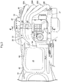
- a body frame F of a motorcycle includes a head pipe 13 which steerably supports a front fork 12 rotatably supporting a front wheel WF, a pair of left and right main frames 14 which extend downwardly and rearwardly from the head pipe 13, a single engine hanger 15 which extends downwardly and rearwardly from the head pipe 13 at a steeper angle than that of the main frames 14, a pair of left and right pivot frames 16 which extend downwardly from the rear portion of the main frames 14, and seat rails 17, which extend upwardly and rearwardly from the rear portion of the main frames 14.
- the main frames 14 and the pivot frames 16 are integrally formed.
- An engine body 18 of a multi-cylinder (here, four-cylinder) engine E which is disposed below the main frames 14, is supported at the rear portion of the main frames 14 of the body frame F, at the lower portion of the engine hanger 15 and at the lower portion of the pivot frames 16.
- a front end portion of a swing arm 19, which rotatably supports at a rear end portion thereof a rear wheel WR driven by the power developed by the engine E is vertically swingably supported at the lower portion of the pivot frames 16.
- a fuel tank 20 is located on the main frames 14 above the engine E, and a rider seat 21 is disposed behind the fuel tank 20 and is supported by the seat rails 17.
- the front fork 12 is covered from the front with a front cover 22, a lower front portion of the fuel tank 20 and the front portion of the body frame F are covered from both sides with a pair of left and right front side covers 23, and a lower rear portion of the fuel tank 20 and the rear portion of the body frame F is covered from both sides with a pair of left and right rear side covers 24 which are disposed below the rider seat 21.
- the engine body 18 of the engine E has: a crankcase 26, which rotatably supports a crankshaft 25 whose axis extends laterally of the body frame F; a cylinder block 27, which is connected to an upper end of a front portion of the crankcase 26 with the cylinder axis inclined forwardly; a cylinder head 28, which is connected to an upper end of the cylinder block 27; and a head cover 29 (see FIG. 1 ), which is connected to an upper end of the cylinder head 28.
- the engine E is configured as an in-line four-cylinder engine.
- an exhaust device 32 is connected to the front of the cylinder head 28, and comprises: a plurality of primary exhaust pipes 33A, 33B, 33C, 33D, upstream ends of which are connected to a front side surface of the cylinder head 28; a collecting exhaust pipe 34, which is commonly connected to downstream end portions of the primary exhaust pipes 33A - 33D; and an exhaust muffler 36, which is connected to a downstream end portion of the collecting exhaust pipe 34 so as to be disposed at the downstream end of the exhaust device 32.
- the exhaust muffler 36 is disposed forwardly of and to the right of the rear wheel WR.
- the engine body 18 is configured with four cylinders, there are four primary exhaust pipes 33A - 33D which are connected to the front side of the cylinder head 28, one for each of the cylinders, and there is a single secondary exhaust pipe (collecting exhaust pipe 34).
- an oil pan 30 is connected to a lower portion of the crankcase 26, and the four primary exhaust pipes 33A - 33D are formed so that they are bent so as to extend downwardly from the front side of the cylinder head 28 and extend rearwardly past the right side of the oil pan 30. Furthermore, while passing the right side of the oil pan 30, the primary exhaust pipes 33A - 33D are arranged in parallel as a row of exhaust pipes, with the row inclined so that the exhaust pipe furthest from the lateral centre of the vehicle is located highest. In addition, the collecting exhaust pipe 34 is disposed to the right of the oil pan 30, and is connected in common to the downstream end portions of all four primary exhaust pipes 33A - 33D.
- the portions of the primary exhaust pipes 33A - 33D which are disposed below the crankcase 26, and the collecting exhaust pipe 34, are covered from the right with an exhaust pipe cover 37 having a first opening 38, through which a part of the portion where the primary exhaust pipes 33A - 33D are connected to the collecting exhaust pipe 34 is exposed.
- the exhaust pipe cover 37 is supported by the crankcase 26 and the pivot frame 16 on the right side.
- most of the exhaust muffler 36 is covered from the right with a muffler protector 39, which is arranged so as to be continuous to the rear portion of the exhaust pipe cover 37, and a tail pipe 41 of the exhaust muffler 36 is located in a second opening 40 which is provided in the muffler protector 39.
- a cap member 42 is attached to the tail pipe 41 so as to close the second opening 40 from inside.
- the collecting exhaust pipe 34 has a contour body 44, which consists of first and second contour members 48, 49 connected with each other so as to form therebetween an exhaust gas flow passage 47 for the exhaust gas from the four primary exhaust pipes 33A - 33D, and a pair of partition wall members 45, 46 which are connected to the contour body 44 and are sandwiched between the first and second contour members 48, 49 so as to divide the inside of the exhaust gas flow passage 47 into at least two parts.
- the first and second contour members 48, 49 are connected with each other in an inclined posture, so that their laterally outer parts are located higher, to the right of the oil pan 30.
- the first and second contour members 48, 49 are connected such that the circumferential portion of the second contour member 49 (the laterally inner contour member) is fitted in the circumferential portion of the first contour member 48 (the laterally outer contour member).
- the primary exhaust pipes 33A - 33D are arranged in parallel while being inclined so that the exhaust pipe furthest from the lateral centre of the vehicle is located highest to the right of the oil pan 30, and the contour body 44 is also disposed to the right of the oil pan 30 and is inclined so that its laterally outer part is located higher.
- a plurality of swelling portions 53, 54, are formed on at least one of the first and second contour members 48, 49 (in this embodiment, on both the first and second contour members 48, 49), and project towards the other contour member, in order to form first and second tubular undulations 51, 52, which have a tubular shape of similar appearance to the four primary exhaust pipes 33A - 33D. These extend continuously and respectively in the direction of each of the primary exhaust pipes 33A - 33D on at least one outer surface of the contour body 44 (in the present embodiment, on both outer surfaces, that is, on the laterally inner surface and the laterally outer surface of the contour body 44).
- the first tubular undulation 51 which is formed on the laterally outer surface of the contour body 44, extends from the upstream end to the downstream end of the contour body 44, in the direction 50 of exhaust gas flow within the exhaust gas flow passage 47, and is formed so as to have a shape where the undulations join at the downstream side.
- the three swelling portions 53 which project towards the second contour member, are formed on the first contour member 48 in order to form the first tubular undulation 51.
- the second tubular undulation 52 which is formed on the laterally inner surface of the contour body 44, is formed so as to correspond only to the upstream part of the first tubular undulation 51.
- the three swelling portions 54 which project towards the first contour member 48, are formed on the upstream part (in the direction 50 of exhaust gas flow) of the second contour member 49 in order to form the second tubular undulation 52.
- a pair of partition wall members 45, 46 are connected to the contour body 44 at a location spaced from a top portion 53a of the swelling portion 53 of the first contour member 48 and a top portion 54a of swelling portion 54 of the second contour member 49, and extend from the upstream portion to the downstream portion of the contour body 44.
- the upstream end and the downstream end (in the direction 50 of exhaust gas flow) of the pair of partition wall members 45, 46 are connected to each other, and a hollow portion 55 is formed between the intermediate portions (in the direction 50 of exhaust gas flow) of the partition wall members 45, 46.
- the partition wall members 45, 46, which divide the exhaust gas flow passage 47 into two branch flow passages 56, 57, are connected to the contour body 44 so as to be sandwiched between the first and second contour members 48, 49.
- facing surfaces 45a, 45b; 46a, 46b at the upstream end and the downstream end of the partition wall members 45, 46 are formed in a flat surface shape so as to abut on each other and to be connected to each other.
- the downstream ends of the partition wall members 45, 46 are disposed in the middle of the contour body 44 in the direction 50 of exhaust gas flow.
- the partition wall members 45, 46 are welded to the first and second contour members 48, 49, so as to be welded to at least one of the first and second contour members 48, 49 from the inside of the contour body 44.
- both partition wall members 45, 46 are welded to the first contour member 48 from the inside of the contour body 44, and are welded to the second contour member 49 from the outside of the contour body 44 through welding holes 58, 59 which are provided in the second contour member 49.
- the welding holes 58, 59 are formed in a curved shape so as to avoid the top portion 54a of the swelling portion 54 provided on the second contour member 49, and the entire area of the portion of the second contour member 49 in which the welding holes 58, 59 are provided is formed in a flat plate shape as shown in FIG.9 .
- connecting pipes 60 which correspond to the four primary exhaust pipes 33A - 33D, are connected to the upstream end portion of the contour body 44 such that a part of each of the connecting pipes 60 is fitted in the upstream end portion of the contour body.
- the downstream end portion of each of the primary exhaust pipes 33A - 33D is fitted into a connecting pipe 60, and the primary exhaust pipes 33A - 33D are welded to the connecting pipes 60. Further, the areas between the connecting pipes 60, 60 are treated with building-up welding, so that there is no opening hole leading into the contour body 44.
- the downstream end portion of the collecting exhaust pipe 34 is connected to the single exhaust muffler 36, such that the downstream end portion of the contour body 44 is fixedly attached to a case 63 of the exhaust muffler 36 and is fitted into a connecting pipe 64 which partially protrudes from the case 63.
- an inner tube 62 which collects the exhaust gas of the exhaust gas flow passage 47 and guides the exhaust gas into the exhaust muffler 36, is inserted in the downstream end portion of the contour body 44.
- the upstream side of the inner tube 62 is formed as an expansion portion 62a, which expands as it extends upstream, and the upstream end of the expansion portion 62a abuts on the inner surface of the contour body 44.
- the upstream end portion of the inner tube 62 (that is, the upstream end portion of the expansion portion 62a) is connected to the contour body 44 of the collecting exhaust pipe 34.
- Elongated welding holes 65, 66 are provided respectively on the first and second contour members 48, 49 at the downstream end portion of the contour body 44 in order to allow the inner tube 62 to be connected.
- the inner tube 62 is welded to the contour body 44 through the welding holes 65, 66.
- a boss member 67 which penetrates the contour body 44 and the inner tube 62, is connected to the downstream end portion of the contour body 44.
- an abutting portion 62b which projects so as to abut on the inner surface of the second contour member 49 of the contour body 44, is formed on the intermediate portion of the inner tube 62 (in the direction 50 of exhaust gas flow).
- the cylindrical boss member 67 is inserted in an insert hole 69 provided in the second contour member 49 as well as in an insert hole 70 provided in the abutting portion 62b so as to correspond to the insert hole 69, and is welded onto the outer surface of the second contour member 49.
- a sensor mounting hole 68 whose outer end is open to the outside and whose inner end is in communication with the inner tube 62, is formed in the boss member 67, so that an exhaust gas sensor attached on the boss member 67 is inserted in the sensor mounting hole 68.
- the collecting exhaust pipe 34 includes the contour body 44, which consists of the first and second contour members 48, 49 connected to each other so as to form therebetween the exhaust gas flow passage 47 for the exhaust gas guided from the four primary exhaust pipes 33A - 33D, and the pair of partition wall members 45, 46 which are connected to the contour body 44 while being sandwiched between the first and second contour members 48, 49 so as to divide the inside of the exhaust gas flow passage 47 into at least two; a plurality of swelling portions 53, 54, which extend towards the other contour member side, are formed on at least one (here, on both) of the first and second contour members 48, 49, in order to form the tubular undulations 51, 52, which have tubular shape similar in appearance to the four primary exhaust pipes 33A - 33D and extend continuously and respectively along each of the primary exhaust pipes 33A - 33D on at least one of outer surfaces (here, on both outer surfaces) of the contour body 44, and the partition wall members 45, 46 are connected to the contour body 44 at locations spaced from the top portions 53a, 54
- the partition wall members 45, 46 are welded respectively to the first and second contour members 48, 49, so as to be welded to at least one of the first and second contour members 48, 49 (here, the first contour member 48) from inside the contour body 44. Accordingly, it is possible to prevent the connection portion with the partition wall members 45, 46 from appearing on the outer surface of at least one of the contour members (here, the first contour member 48) forming the contour body 44, which thereby avoids the disfigurement of the external appearance of the outer surface of the contour body 44 on which the appearance design is applied so as to have the tubular undulations.
- partition wall members 45, 46 are welded to the first contour member 48 out of the first and second contour members 48, 49 from inside the contour body 44 and to the second contour member 49 through the welding holes 58, 59, which are provided in the second contour member 49, from outside of the contour body 44, which thereby facilitate connection of the partition wall members 45, 46 to the contour body 44.
- the entire area of the portion of the second contour member 49 in which the welding holes 58, 59 are provided is formed in a flat plate shape, which thereby not only can facilitate the welding operation, but also can enhance the bonding strength of the partition wall members 45, 46 to the contour body 44.
- the upstream and downstream ends of the exhaust gas flow passage 47 are connected with each other forming the hollow portion 55 between the intermediate portions of the partition wall members, and the partition wall members 45, 46, which divide the exhaust gas flow passage 47 into the two branch flow passages 56, 57, are connected to the contour body 44 so as to be sandwiched between the first and second contour members 48, 49. Accordingly, it is possible to freely design the two branch flow passages 56, 57, which can be obtained by partitioning the exhaust gas flow passage 47 into two with the partition wall members 45, 46, regardless of the undulating shape of the outer surface of the contour body 44.
- the downstream ends (in the direction 50 of exhaust gas flow) of the partition wall members 45, 46 are disposed in the middle of the contour body 44, which thereby allows the manifold portion of the two branch flow passages 56, 57 in the collecting exhaust pipe 34 to be freely and easily designed.
- the facing surfaces 45a, 45b; 46a, 46b of the upstream end portion and the downstream end portion of the partition wall members 45, 46 are formed in a flat plate shape so as to abut on each other and to be connected to each other. Accordingly, it is possible to increase the airtightness of the connecting portion of both partition wall members 45, 46, and to smoothly circulate the exhaust gas to both sides of both partition wall members 45, 46 while preventing the exhaust gas from flowing in the hollow portion 55 between the partition wall members 45, 46.
- downstream end portion of the collecting exhaust pipe 34 is connected to the single exhaust muffler 36, the inner tube 62 which collects the exhaust gas of the exhaust gas flow passage 47 and guides the exhaust gas into the exhaust muffler 36 is inserted in the downstream end portion of the contour body 44, and the upstream end portion of the inner tube 62 is connected to the contour body 44. Accordingly, it is possible to make the downstream end portion of the collecting exhaust pipe 34 into a double-layer pipe structure, and to smoothly guide the exhaust gas, which meets in the inner tube inserted in the downstream end portion of the collecting exhaust pipe 34, into the exhaust muffler 36.
- the boss member 67 which penetrates the contour body 44 and the inner tube 62, is connected to the downstream end portion of the contour body 44, and the sensor mounting hole 68, whose outer end is open to the outside and whose inner end is in communication with the inner tube 62, is formed in the boss member 67 so that an exhaust gas sensor attached on the boss member 67 can be inserted into the sensor mounting hole. Accordingly, it is possible to detect the exhaust gas circulating in the inner tube 62 at the part of the double-layer pipe structure formed in the downstream end portion of the collecting exhaust pipe 34 by using a single exhaust gas sensor.
Landscapes
- Engineering & Computer Science (AREA)
- Chemical & Material Sciences (AREA)
- Combustion & Propulsion (AREA)
- Mechanical Engineering (AREA)
- General Engineering & Computer Science (AREA)
- Exhaust Silencers (AREA)
Claims (8)
- Eine Abgasvorrichtung für ein Motorrad umfassend:eine Vielzahl von ersten Abgasrohren (33A, 33B, 33C, 33D), von denen jeder zu einem Zylinder von einem Multizylindermotorkörper (18), welcher auf einem Körperahmen (F) montiert ist, verbunden ist,ein Sammelabgasrohr (34), welches gemeinsam zu den stromabwärtigen Endabschnitten von den ersten Abgasrohren (33A - 33D) verbunden ist,wobei besagtes Sammelabgasrohr (34) einen Konturkörper (44) aufweist, welcher aus einem Paar von Konturelementen (48, 49) besteht, derart verbunden zu jeden anderen, um dazwischen eine Abgasflusspassage (47) für das Abgas, welches von der besagten Vielfalt von ersten Abgasrohren (33A - 33D) geleitet wird, zu bilden, undTrennwandelementen (45, 46), welche zu besagtem Konturkörper (44) verbunden sind, während sie zwischen besagten Konturelementen (48, 49) derart eingeklemmt sind, um das Innere von besagten Abgasflusspassagen (47) zumindest in zwei zu trennen,wobei eine Vielzahl von Schwellungsabschnitten (53, 54), welche in Richtung zu besagtem anderen Konturelement vorstehen, auf zumindest einen von besagten Konturelementen (48, 49) gebildet sind, um Rohrwellen (51, 52) zu bilden, welche ein rohrförmige Form aufweisen, ähnlich im Aussehen zur besagten Vielzahl von ersten Abgasrohren (33A - 33D) und kontinuierlich und jeweils in die gleiche Richtung sich erstrecken wie die ersten Abgasrohre (33A - 33D) auf zumindest einer äußeren Oberfläche von besagtem Konturkörper (44), undbesagte Trennwandelemente (45, 46) sind verbunden zu besagtem Konturkörper (44) an einem Ort, welcher von den Abschnitten (53a, 54a) von besagten Schwellungsabschnitten (53, 54) beabstandet ist, welche in Richtung des Inneren von den Sammelabgasrohr (34) heraus von den Rohrwellen (51, 52) geschwollen sind und sich von einer stromaufwärtigen Region zu einer stromabwärtigen Region von besagtem Konturkörper (44) in der Richtung (50) von dem Abgasfluss in besagter Abgasflusspassage (47) erstrecken;dadurch gekennzeichnet, dassdie stromaufwärtigen und stromabwärtigen Endabschnitte in der Richtung (50) vom Abgasfluss von besagten Trennwandelementen (48, 49) verbunden sind und einen hohlen Abschnitt (55) zwischen den Zwischenabschnitten von den Trennwandelementen (48, 49) bilden, undbesagte Trennwandelemente (48, 49), welche besagte Abgasflusspassage (47) in zwei Zweigflusspassagen (56, 57) trennen, derart verbunden sind zu besagtem Konturkörper (44), um zwischen besagten Konturelementen (48, 49) eingeklemmt zu sein.
- Eine Abgasvorrichtung für ein Motorrad wie in Anspruch 1 beansprucht, wobei besagte Trennwandelemente (45, 46) jeweils zu den Konturelementen geschweißt sind, um zu zumindest einem von besagten Konturelementen (48, 49) vom Inneren von besagtem Konturköper (44) geschweißt zu sein.
- Eine Abgasvorrichtung für ein Motorrad wie in Anspruch 2 beansprucht, wobei besagte Trennwandelemente (45, 46) zu einem von besagten Konturelementen (48, 49) vom Inneren von besagtem Konturkörper (44) geschweißt sind und zu dem anderen von besagten Konturelementen (49, 48) von Außen von dem Konturkörper (44) durch Schweißlöcher (58, 59), welche in dem besagten anderen Konturelement (49, 48) vorgesehen sind.
- Eine Abgasvorrichtung für ein Motorrad wie in Anspruch 3 beansprucht, wobei der gesamte Bereich von dem Abschnitt von dem anderen Konturelement (49, 48), in welchem besagte Schweißlöcher (58, 59) vorgesehen sind, in einer flachen Plattenform gebildet ist.
- Eine Abgasvorrichtung für ein Motorrad wie in irgendeinem vorherigen Anspruch beansprucht, wobei die stromabwärtigen Enden von besagten Trennwandelementen (45, 46) in der Mitte von besagten Konturkörpern (44) in der Richtung (50) von dem Abgasfluss geneigt sind.
- Eine Abgasvorrichtung für ein Motorrad wie in irgendeinem vorherigen Anspruch beansprucht, wobei gegenüberliegende Oberflächen (45a, 45b, 46a, 46b) von dem stromaufwärtigen Endabschnitt und dem stromabwärtigen Endabschnitt von besagtem Trennwandelementen (45, 46) in einer flachen Oberflächenform derart gebildet sind, um aneinander zu grenzen und zueinander verbunden zu sein.
- Eine Abgasvorrichtung für ein Motorrad wie in irgendeinem vorherigen Anspruch beansprucht, wobeiein stromabwärtiger Endabschnitt von besagtem Sammelabgasrohr (34) zu einem einzelnen Abgasschalldämpfer (36) ver-bunden ist,eine inneres Rohr (62), welches das Abgas von besagter Abgasflusspassage (47) sammelt und das Abgas in besagten Abgasschalldämpfer (36) leitet, ist in den stromabwärtigen Endabschnitt von besagtem Konturkörper (44) eingeführt, undein stromaufwärtiger Endabschnitt von dem inneren Rohr (62) ist zu besagtem Konturkörper (44) verbunden.
- Eine Abgasvorrichtung für ein Motorrad wie in Anspruch 7 beansprucht, wobeiein Knaufteil (67), welches den Konturkörper (44) und besagtes inneres Rohr (62) durchsticht, verbunden ist zu dem stromabwärtigen Endabschnitt von besagtem Konturkörper (44) undein Sensor - Befestigungsloch (68), dessen äußeres Ende nach Außen offen ist und dessen inneres Ende in Verbindung mit besagtem inneren Rohr (62) ist, in dem Knaufteil (67) derart gebildet ist, dass ein Abgassensor, welcher auf besagtem Knaufteil (67) befestigt ist, in das Sensor - Befestigungsloch eingeführt ist.
Applications Claiming Priority (1)
| Application Number | Priority Date | Filing Date | Title |
|---|---|---|---|
| JP2013115870A JP6168853B2 (ja) | 2013-05-31 | 2013-05-31 | 自動二輪車用排気装置 |
Publications (2)
| Publication Number | Publication Date |
|---|---|
| EP2813680A1 EP2813680A1 (de) | 2014-12-17 |
| EP2813680B1 true EP2813680B1 (de) | 2017-01-11 |
Family
ID=50389280
Family Applications (1)
| Application Number | Title | Priority Date | Filing Date |
|---|---|---|---|
| EP14162060.9A Active EP2813680B1 (de) | 2013-05-31 | 2014-03-27 | Abgasvorrichtung für ein Motorrad |
Country Status (4)
| Country | Link |
|---|---|
| US (1) | US9188049B2 (de) |
| EP (1) | EP2813680B1 (de) |
| JP (1) | JP6168853B2 (de) |
| BR (1) | BR102014012090A2 (de) |
Families Citing this family (4)
| Publication number | Priority date | Publication date | Assignee | Title |
|---|---|---|---|---|
| JP6378611B2 (ja) * | 2014-10-29 | 2018-08-22 | 川崎重工業株式会社 | エンジンの排気装置 |
| JP6266549B2 (ja) * | 2015-02-25 | 2018-01-24 | 本田技研工業株式会社 | 自動二輪車の排気装置 |
| JP6720326B2 (ja) | 2016-09-28 | 2020-07-08 | 本田技研工業株式会社 | 鞍乗型車両の排気装置 |
| JP6790034B2 (ja) | 2018-09-11 | 2020-11-25 | 本田技研工業株式会社 | 直列4気筒内燃機関の排気管構造 |
Family Cites Families (22)
| Publication number | Priority date | Publication date | Assignee | Title |
|---|---|---|---|---|
| JPS62731Y2 (de) | 1980-07-28 | 1987-01-09 | ||
| JPS57140509A (en) * | 1981-02-23 | 1982-08-31 | Yamaha Motor Co Ltd | Structure of manifold exhaust pipes |
| JPS60198320A (ja) * | 1984-03-23 | 1985-10-07 | Yamaha Motor Co Ltd | 自動二輪車用多気筒エンジンの排気装置 |
| JPS62731U (de) * | 1985-06-19 | 1987-01-06 | ||
| US4850189A (en) * | 1987-10-14 | 1989-07-25 | Arvin Industries, Inc. | Manifold baffle system |
| JP2858326B2 (ja) * | 1989-09-06 | 1999-02-17 | スズキ株式会社 | 並列四気筒四サイクルエンジンの排気装置 |
| JPH062731A (ja) | 1992-06-17 | 1994-01-11 | Kayaba Ind Co Ltd | 緩衝器 |
| US6283162B1 (en) * | 1999-09-09 | 2001-09-04 | Boyd L. Butler | Thin boom tube exhaust pipes, method of sheet metal construction thereof, and exhaust systems which utilize such exhaust pipes for increased ground clearance on race cars |
| US6634171B1 (en) * | 1999-10-27 | 2003-10-21 | Banks, Iii Gale C. | Exhaust scavenging system |
| US6478340B1 (en) * | 2000-03-30 | 2002-11-12 | Boyd L. Butler | Y-pipe for thin boom tube exhaust pipes providing increased ground clearance on race cars |
| JP2002276356A (ja) * | 2001-03-19 | 2002-09-25 | Mazda Motor Corp | 車載用エンジンの排気構造 |
| JP4096791B2 (ja) * | 2003-04-16 | 2008-06-04 | 日産自動車株式会社 | 内燃機関の排気装置 |
| JP2005163623A (ja) * | 2003-12-02 | 2005-06-23 | Calsonic Kansei Corp | エキゾーストマニホールド |
| JP2007154660A (ja) * | 2005-11-30 | 2007-06-21 | Futaba Industrial Co Ltd | エギゾーストマニホルド |
| JP2008133823A (ja) * | 2006-10-31 | 2008-06-12 | Yamaha Motor Co Ltd | 車両 |
| JP2008115797A (ja) * | 2006-11-06 | 2008-05-22 | Calsonic Kansei Corp | エキゾーストマニホールドの集合部構造 |
| JP4918392B2 (ja) * | 2007-04-19 | 2012-04-18 | 株式会社ユタカ技研 | 多気筒エンジンの排気集合部 |
| US9151208B2 (en) * | 2008-03-13 | 2015-10-06 | Borgwarner Inc. | Exhaust manifold of an internal combustion engine |
| JP2009257247A (ja) * | 2008-04-18 | 2009-11-05 | Futaba Industrial Co Ltd | エギゾーストマニホルド |
| JP4624460B2 (ja) * | 2008-11-25 | 2011-02-02 | トヨタ自動車株式会社 | 排気マニホールド |
| JP4624459B2 (ja) * | 2008-11-25 | 2011-02-02 | トヨタ自動車株式会社 | 排気マニホールド |
| JP5484374B2 (ja) * | 2011-02-17 | 2014-05-07 | 本田技研工業株式会社 | 排気マフラー |
-
2013
- 2013-05-31 JP JP2013115870A patent/JP6168853B2/ja active Active
-
2014
- 2014-03-27 EP EP14162060.9A patent/EP2813680B1/de active Active
- 2014-05-20 BR BRBR102014012090-4A patent/BR102014012090A2/pt not_active IP Right Cessation
- 2014-05-22 US US14/285,040 patent/US9188049B2/en active Active
Non-Patent Citations (1)
| Title |
|---|
| None * |
Also Published As
| Publication number | Publication date |
|---|---|
| BR102014012090A2 (pt) | 2015-03-31 |
| JP2014234750A (ja) | 2014-12-15 |
| EP2813680A1 (de) | 2014-12-17 |
| US20140352288A1 (en) | 2014-12-04 |
| US9188049B2 (en) | 2015-11-17 |
| JP6168853B2 (ja) | 2017-07-26 |
Similar Documents
| Publication | Publication Date | Title |
|---|---|---|
| US9004209B2 (en) | Front air guide structure for a motorcycle | |
| JP4901554B2 (ja) | 自動2輪車の排気装置 | |
| EP2813680B1 (de) | Abgasvorrichtung für ein Motorrad | |
| EP2620608B1 (de) | Abgassystem eines Motors | |
| JP2014069624A5 (de) | ||
| US8479862B2 (en) | Motorcycle exhaust device | |
| JP6120457B2 (ja) | 内燃機関の排気装置 | |
| US5568726A (en) | Exhaust pipe structure for a motorcycle | |
| JP5789377B2 (ja) | 自動二輪車の排気系構造 | |
| JP5899108B2 (ja) | 車両の吸気装置 | |
| JP4668231B2 (ja) | エンジンの排気装置 | |
| US9556833B2 (en) | Motorcycle | |
| EP1900917B1 (de) | Motorrad | |
| JPH0510122A (ja) | 横置エンジンの排気装置 | |
| BR102015019179A2 (pt) | sistema de admissão de veículo | |
| JP6813664B2 (ja) | 鞍乗り型車両用内燃機関の排気装置 | |
| JP2017149166A (ja) | 鞍乗型車両 | |
| JP5602121B2 (ja) | 排気センサーの取付け構造 | |
| JPS5815710A (ja) | 自動二輪車用v型内燃エンジンの排気管装置 | |
| JP2000248947A (ja) | 自動二輪車の排気装置 | |
| JP2017149167A (ja) | 鞍乗型車両 | |
| JP2001041076A5 (de) | ||
| JPS6069230A (ja) | 自動二輪車の排気装置 | |
| JPWO2018061120A1 (ja) | 鞍乗型車両の排気装置 | |
| JPS61160512A (ja) | 車両用エンジンのエキゾ−ストパイプ集合部構造 |
Legal Events
| Date | Code | Title | Description |
|---|---|---|---|
| 17P | Request for examination filed |
Effective date: 20140327 |
|
| AK | Designated contracting states |
Kind code of ref document: A1 Designated state(s): AL AT BE BG CH CY CZ DE DK EE ES FI FR GB GR HR HU IE IS IT LI LT LU LV MC MK MT NL NO PL PT RO RS SE SI SK SM TR |
|
| AX | Request for extension of the european patent |
Extension state: BA ME |
|
| PUAI | Public reference made under article 153(3) epc to a published international application that has entered the european phase |
Free format text: ORIGINAL CODE: 0009012 |
|
| 17Q | First examination report despatched |
Effective date: 20151124 |
|
| GRAP | Despatch of communication of intention to grant a patent |
Free format text: ORIGINAL CODE: EPIDOSNIGR1 |
|
| INTG | Intention to grant announced |
Effective date: 20160720 |
|
| GRAS | Grant fee paid |
Free format text: ORIGINAL CODE: EPIDOSNIGR3 |
|
| GRAA | (expected) grant |
Free format text: ORIGINAL CODE: 0009210 |
|
| AK | Designated contracting states |
Kind code of ref document: B1 Designated state(s): AL AT BE BG CH CY CZ DE DK EE ES FI FR GB GR HR HU IE IS IT LI LT LU LV MC MK MT NL NO PL PT RO RS SE SI SK SM TR |
|
| REG | Reference to a national code |
Ref country code: GB Ref legal event code: FG4D |
|
| REG | Reference to a national code |
Ref country code: CH Ref legal event code: EP |
|
| REG | Reference to a national code |
Ref country code: AT Ref legal event code: REF Ref document number: 861509 Country of ref document: AT Kind code of ref document: T Effective date: 20170115 |
|
| REG | Reference to a national code |
Ref country code: IE Ref legal event code: FG4D |
|
| REG | Reference to a national code |
Ref country code: DE Ref legal event code: R096 Ref document number: 602014006121 Country of ref document: DE |
|
| REG | Reference to a national code |
Ref country code: LT Ref legal event code: MG4D |
|
| REG | Reference to a national code |
Ref country code: NL Ref legal event code: MP Effective date: 20170111 |
|
| REG | Reference to a national code |
Ref country code: AT Ref legal event code: MK05 Ref document number: 861509 Country of ref document: AT Kind code of ref document: T Effective date: 20170111 |
|
| PG25 | Lapsed in a contracting state [announced via postgrant information from national office to epo] |
Ref country code: NL Free format text: LAPSE BECAUSE OF FAILURE TO SUBMIT A TRANSLATION OF THE DESCRIPTION OR TO PAY THE FEE WITHIN THE PRESCRIBED TIME-LIMIT Effective date: 20170111 |
|
| PG25 | Lapsed in a contracting state [announced via postgrant information from national office to epo] |
Ref country code: FI Free format text: LAPSE BECAUSE OF FAILURE TO SUBMIT A TRANSLATION OF THE DESCRIPTION OR TO PAY THE FEE WITHIN THE PRESCRIBED TIME-LIMIT Effective date: 20170111 Ref country code: IS Free format text: LAPSE BECAUSE OF FAILURE TO SUBMIT A TRANSLATION OF THE DESCRIPTION OR TO PAY THE FEE WITHIN THE PRESCRIBED TIME-LIMIT Effective date: 20170511 Ref country code: HR Free format text: LAPSE BECAUSE OF FAILURE TO SUBMIT A TRANSLATION OF THE DESCRIPTION OR TO PAY THE FEE WITHIN THE PRESCRIBED TIME-LIMIT Effective date: 20170111 Ref country code: LT Free format text: LAPSE BECAUSE OF FAILURE TO SUBMIT A TRANSLATION OF THE DESCRIPTION OR TO PAY THE FEE WITHIN THE PRESCRIBED TIME-LIMIT Effective date: 20170111 Ref country code: NO Free format text: LAPSE BECAUSE OF FAILURE TO SUBMIT A TRANSLATION OF THE DESCRIPTION OR TO PAY THE FEE WITHIN THE PRESCRIBED TIME-LIMIT Effective date: 20170411 Ref country code: GR Free format text: LAPSE BECAUSE OF FAILURE TO SUBMIT A TRANSLATION OF THE DESCRIPTION OR TO PAY THE FEE WITHIN THE PRESCRIBED TIME-LIMIT Effective date: 20170412 |
|
| PG25 | Lapsed in a contracting state [announced via postgrant information from national office to epo] |
Ref country code: AT Free format text: LAPSE BECAUSE OF FAILURE TO SUBMIT A TRANSLATION OF THE DESCRIPTION OR TO PAY THE FEE WITHIN THE PRESCRIBED TIME-LIMIT Effective date: 20170111 Ref country code: LV Free format text: LAPSE BECAUSE OF FAILURE TO SUBMIT A TRANSLATION OF THE DESCRIPTION OR TO PAY THE FEE WITHIN THE PRESCRIBED TIME-LIMIT Effective date: 20170111 Ref country code: ES Free format text: LAPSE BECAUSE OF FAILURE TO SUBMIT A TRANSLATION OF THE DESCRIPTION OR TO PAY THE FEE WITHIN THE PRESCRIBED TIME-LIMIT Effective date: 20170111 Ref country code: BG Free format text: LAPSE BECAUSE OF FAILURE TO SUBMIT A TRANSLATION OF THE DESCRIPTION OR TO PAY THE FEE WITHIN THE PRESCRIBED TIME-LIMIT Effective date: 20170411 Ref country code: PL Free format text: LAPSE BECAUSE OF FAILURE TO SUBMIT A TRANSLATION OF THE DESCRIPTION OR TO PAY THE FEE WITHIN THE PRESCRIBED TIME-LIMIT Effective date: 20170111 Ref country code: SE Free format text: LAPSE BECAUSE OF FAILURE TO SUBMIT A TRANSLATION OF THE DESCRIPTION OR TO PAY THE FEE WITHIN THE PRESCRIBED TIME-LIMIT Effective date: 20170111 Ref country code: RS Free format text: LAPSE BECAUSE OF FAILURE TO SUBMIT A TRANSLATION OF THE DESCRIPTION OR TO PAY THE FEE WITHIN THE PRESCRIBED TIME-LIMIT Effective date: 20170111 Ref country code: PT Free format text: LAPSE BECAUSE OF FAILURE TO SUBMIT A TRANSLATION OF THE DESCRIPTION OR TO PAY THE FEE WITHIN THE PRESCRIBED TIME-LIMIT Effective date: 20170511 |
|
| REG | Reference to a national code |
Ref country code: DE Ref legal event code: R097 Ref document number: 602014006121 Country of ref document: DE |
|
| PG25 | Lapsed in a contracting state [announced via postgrant information from national office to epo] |
Ref country code: SK Free format text: LAPSE BECAUSE OF FAILURE TO SUBMIT A TRANSLATION OF THE DESCRIPTION OR TO PAY THE FEE WITHIN THE PRESCRIBED TIME-LIMIT Effective date: 20170111 Ref country code: CZ Free format text: LAPSE BECAUSE OF FAILURE TO SUBMIT A TRANSLATION OF THE DESCRIPTION OR TO PAY THE FEE WITHIN THE PRESCRIBED TIME-LIMIT Effective date: 20170111 Ref country code: RO Free format text: LAPSE BECAUSE OF FAILURE TO SUBMIT A TRANSLATION OF THE DESCRIPTION OR TO PAY THE FEE WITHIN THE PRESCRIBED TIME-LIMIT Effective date: 20170111 Ref country code: EE Free format text: LAPSE BECAUSE OF FAILURE TO SUBMIT A TRANSLATION OF THE DESCRIPTION OR TO PAY THE FEE WITHIN THE PRESCRIBED TIME-LIMIT Effective date: 20170111 |
|
| REG | Reference to a national code |
Ref country code: CH Ref legal event code: PL |
|
| PLBE | No opposition filed within time limit |
Free format text: ORIGINAL CODE: 0009261 |
|
| STAA | Information on the status of an ep patent application or granted ep patent |
Free format text: STATUS: NO OPPOSITION FILED WITHIN TIME LIMIT |
|
| PG25 | Lapsed in a contracting state [announced via postgrant information from national office to epo] |
Ref country code: DK Free format text: LAPSE BECAUSE OF FAILURE TO SUBMIT A TRANSLATION OF THE DESCRIPTION OR TO PAY THE FEE WITHIN THE PRESCRIBED TIME-LIMIT Effective date: 20170111 Ref country code: MC Free format text: LAPSE BECAUSE OF FAILURE TO SUBMIT A TRANSLATION OF THE DESCRIPTION OR TO PAY THE FEE WITHIN THE PRESCRIBED TIME-LIMIT Effective date: 20170111 Ref country code: SM Free format text: LAPSE BECAUSE OF FAILURE TO SUBMIT A TRANSLATION OF THE DESCRIPTION OR TO PAY THE FEE WITHIN THE PRESCRIBED TIME-LIMIT Effective date: 20170111 |
|
| 26N | No opposition filed |
Effective date: 20171012 |
|
| REG | Reference to a national code |
Ref country code: IE Ref legal event code: MM4A |
|
| REG | Reference to a national code |
Ref country code: FR Ref legal event code: ST Effective date: 20171130 |
|
| PG25 | Lapsed in a contracting state [announced via postgrant information from national office to epo] |
Ref country code: FR Free format text: LAPSE BECAUSE OF NON-PAYMENT OF DUE FEES Effective date: 20170331 Ref country code: LU Free format text: LAPSE BECAUSE OF NON-PAYMENT OF DUE FEES Effective date: 20170327 |
|
| PG25 | Lapsed in a contracting state [announced via postgrant information from national office to epo] |
Ref country code: IE Free format text: LAPSE BECAUSE OF NON-PAYMENT OF DUE FEES Effective date: 20170327 Ref country code: SI Free format text: LAPSE BECAUSE OF FAILURE TO SUBMIT A TRANSLATION OF THE DESCRIPTION OR TO PAY THE FEE WITHIN THE PRESCRIBED TIME-LIMIT Effective date: 20170111 Ref country code: CH Free format text: LAPSE BECAUSE OF NON-PAYMENT OF DUE FEES Effective date: 20170331 Ref country code: LI Free format text: LAPSE BECAUSE OF NON-PAYMENT OF DUE FEES Effective date: 20170331 |
|
| REG | Reference to a national code |
Ref country code: BE Ref legal event code: MM Effective date: 20170331 |
|
| PGFP | Annual fee paid to national office [announced via postgrant information from national office to epo] |
Ref country code: GB Payment date: 20180321 Year of fee payment: 5 |
|
| PG25 | Lapsed in a contracting state [announced via postgrant information from national office to epo] |
Ref country code: BE Free format text: LAPSE BECAUSE OF NON-PAYMENT OF DUE FEES Effective date: 20170331 |
|
| PGFP | Annual fee paid to national office [announced via postgrant information from national office to epo] |
Ref country code: IT Payment date: 20180321 Year of fee payment: 5 |
|
| PG25 | Lapsed in a contracting state [announced via postgrant information from national office to epo] |
Ref country code: MT Free format text: LAPSE BECAUSE OF NON-PAYMENT OF DUE FEES Effective date: 20170327 |
|
| PG25 | Lapsed in a contracting state [announced via postgrant information from national office to epo] |
Ref country code: HU Free format text: LAPSE BECAUSE OF FAILURE TO SUBMIT A TRANSLATION OF THE DESCRIPTION OR TO PAY THE FEE WITHIN THE PRESCRIBED TIME-LIMIT; INVALID AB INITIO Effective date: 20140327 |
|
| PG25 | Lapsed in a contracting state [announced via postgrant information from national office to epo] |
Ref country code: CY Free format text: LAPSE BECAUSE OF FAILURE TO SUBMIT A TRANSLATION OF THE DESCRIPTION OR TO PAY THE FEE WITHIN THE PRESCRIBED TIME-LIMIT Effective date: 20170111 |
|
| GBPC | Gb: european patent ceased through non-payment of renewal fee |
Effective date: 20190327 |
|
| PG25 | Lapsed in a contracting state [announced via postgrant information from national office to epo] |
Ref country code: MK Free format text: LAPSE BECAUSE OF FAILURE TO SUBMIT A TRANSLATION OF THE DESCRIPTION OR TO PAY THE FEE WITHIN THE PRESCRIBED TIME-LIMIT Effective date: 20170111 |
|
| REG | Reference to a national code |
Ref country code: DE Ref legal event code: R084 Ref document number: 602014006121 Country of ref document: DE |
|
| PG25 | Lapsed in a contracting state [announced via postgrant information from national office to epo] |
Ref country code: GB Free format text: LAPSE BECAUSE OF NON-PAYMENT OF DUE FEES Effective date: 20190327 |
|
| PG25 | Lapsed in a contracting state [announced via postgrant information from national office to epo] |
Ref country code: IT Free format text: LAPSE BECAUSE OF NON-PAYMENT OF DUE FEES Effective date: 20190327 |
|
| PG25 | Lapsed in a contracting state [announced via postgrant information from national office to epo] |
Ref country code: TR Free format text: LAPSE BECAUSE OF FAILURE TO SUBMIT A TRANSLATION OF THE DESCRIPTION OR TO PAY THE FEE WITHIN THE PRESCRIBED TIME-LIMIT Effective date: 20170111 |
|
| PG25 | Lapsed in a contracting state [announced via postgrant information from national office to epo] |
Ref country code: AL Free format text: LAPSE BECAUSE OF FAILURE TO SUBMIT A TRANSLATION OF THE DESCRIPTION OR TO PAY THE FEE WITHIN THE PRESCRIBED TIME-LIMIT Effective date: 20170111 |
|
| REG | Reference to a national code |
Ref country code: DE Ref legal event code: R082 Ref document number: 602014006121 Country of ref document: DE |
|
| PGFP | Annual fee paid to national office [announced via postgrant information from national office to epo] |
Ref country code: DE Payment date: 20250218 Year of fee payment: 12 |