EP2809559B1 - Procede pour faire fonctionner un systeme de freinage de vehicules à moteur et systeme de freinage - Google Patents
Procede pour faire fonctionner un systeme de freinage de vehicules à moteur et systeme de freinage Download PDFInfo
- Publication number
- EP2809559B1 EP2809559B1 EP13701110.2A EP13701110A EP2809559B1 EP 2809559 B1 EP2809559 B1 EP 2809559B1 EP 13701110 A EP13701110 A EP 13701110A EP 2809559 B1 EP2809559 B1 EP 2809559B1
- Authority
- EP
- European Patent Office
- Prior art keywords
- pedal
- brake
- pressure
- operating mode
- supply device
- Prior art date
- Legal status (The legal status is an assumption and is not a legal conclusion. Google has not performed a legal analysis and makes no representation as to the accuracy of the status listed.)
- Not-in-force
Links
- 238000000034 method Methods 0.000 title claims description 32
- 230000004913 activation Effects 0.000 claims description 6
- 238000007599 discharging Methods 0.000 claims description 3
- 230000003213 activating effect Effects 0.000 claims 2
- 238000012937 correction Methods 0.000 description 10
- 238000002955 isolation Methods 0.000 description 9
- 230000007704 transition Effects 0.000 description 7
- 238000010586 diagram Methods 0.000 description 6
- 238000006073 displacement reaction Methods 0.000 description 5
- 239000012530 fluid Substances 0.000 description 5
- 230000001105 regulatory effect Effects 0.000 description 4
- 238000013461 design Methods 0.000 description 2
- 238000013519 translation Methods 0.000 description 2
- 206010016173 Fall Diseases 0.000 description 1
- 230000009471 action Effects 0.000 description 1
- 230000006978 adaptation Effects 0.000 description 1
- 238000013459 approach Methods 0.000 description 1
- 230000008901 benefit Effects 0.000 description 1
- 230000006835 compression Effects 0.000 description 1
- 238000007906 compression Methods 0.000 description 1
- 238000001514 detection method Methods 0.000 description 1
- 229920001971 elastomer Polymers 0.000 description 1
- 239000000806 elastomer Substances 0.000 description 1
- 230000007613 environmental effect Effects 0.000 description 1
- 230000007794 irritation Effects 0.000 description 1
- 230000008569 process Effects 0.000 description 1
- 230000000750 progressive effect Effects 0.000 description 1
- 238000012546 transfer Methods 0.000 description 1
Images


Classifications
-
- B—PERFORMING OPERATIONS; TRANSPORTING
- B60—VEHICLES IN GENERAL
- B60T—VEHICLE BRAKE CONTROL SYSTEMS OR PARTS THEREOF; BRAKE CONTROL SYSTEMS OR PARTS THEREOF, IN GENERAL; ARRANGEMENT OF BRAKING ELEMENTS ON VEHICLES IN GENERAL; PORTABLE DEVICES FOR PREVENTING UNWANTED MOVEMENT OF VEHICLES; VEHICLE MODIFICATIONS TO FACILITATE COOLING OF BRAKES
- B60T11/00—Transmitting braking action from initiating means to ultimate brake actuator without power assistance or drive or where such assistance or drive is irrelevant
- B60T11/10—Transmitting braking action from initiating means to ultimate brake actuator without power assistance or drive or where such assistance or drive is irrelevant transmitting by fluid means, e.g. hydraulic
- B60T11/103—Transmitting braking action from initiating means to ultimate brake actuator without power assistance or drive or where such assistance or drive is irrelevant transmitting by fluid means, e.g. hydraulic in combination with other control devices
-
- B—PERFORMING OPERATIONS; TRANSPORTING
- B60—VEHICLES IN GENERAL
- B60T—VEHICLE BRAKE CONTROL SYSTEMS OR PARTS THEREOF; BRAKE CONTROL SYSTEMS OR PARTS THEREOF, IN GENERAL; ARRANGEMENT OF BRAKING ELEMENTS ON VEHICLES IN GENERAL; PORTABLE DEVICES FOR PREVENTING UNWANTED MOVEMENT OF VEHICLES; VEHICLE MODIFICATIONS TO FACILITATE COOLING OF BRAKES
- B60T8/00—Arrangements for adjusting wheel-braking force to meet varying vehicular or ground-surface conditions, e.g. limiting or varying distribution of braking force
- B60T8/32—Arrangements for adjusting wheel-braking force to meet varying vehicular or ground-surface conditions, e.g. limiting or varying distribution of braking force responsive to a speed condition, e.g. acceleration or deceleration
- B60T8/34—Arrangements for adjusting wheel-braking force to meet varying vehicular or ground-surface conditions, e.g. limiting or varying distribution of braking force responsive to a speed condition, e.g. acceleration or deceleration having a fluid pressure regulator responsive to a speed condition
- B60T8/40—Arrangements for adjusting wheel-braking force to meet varying vehicular or ground-surface conditions, e.g. limiting or varying distribution of braking force responsive to a speed condition, e.g. acceleration or deceleration having a fluid pressure regulator responsive to a speed condition comprising an additional fluid circuit including fluid pressurising means for modifying the pressure of the braking fluid, e.g. including wheel driven pumps for detecting a speed condition, or pumps which are controlled by means independent of the braking system
- B60T8/4072—Systems in which a driver input signal is used as a control signal for the additional fluid circuit which is normally used for braking
- B60T8/4081—Systems with stroke simulating devices for driver input
-
- B—PERFORMING OPERATIONS; TRANSPORTING
- B60—VEHICLES IN GENERAL
- B60T—VEHICLE BRAKE CONTROL SYSTEMS OR PARTS THEREOF; BRAKE CONTROL SYSTEMS OR PARTS THEREOF, IN GENERAL; ARRANGEMENT OF BRAKING ELEMENTS ON VEHICLES IN GENERAL; PORTABLE DEVICES FOR PREVENTING UNWANTED MOVEMENT OF VEHICLES; VEHICLE MODIFICATIONS TO FACILITATE COOLING OF BRAKES
- B60T11/00—Transmitting braking action from initiating means to ultimate brake actuator without power assistance or drive or where such assistance or drive is irrelevant
- B60T11/10—Transmitting braking action from initiating means to ultimate brake actuator without power assistance or drive or where such assistance or drive is irrelevant transmitting by fluid means, e.g. hydraulic
- B60T11/16—Master control, e.g. master cylinders
-
- B—PERFORMING OPERATIONS; TRANSPORTING
- B60—VEHICLES IN GENERAL
- B60T—VEHICLE BRAKE CONTROL SYSTEMS OR PARTS THEREOF; BRAKE CONTROL SYSTEMS OR PARTS THEREOF, IN GENERAL; ARRANGEMENT OF BRAKING ELEMENTS ON VEHICLES IN GENERAL; PORTABLE DEVICES FOR PREVENTING UNWANTED MOVEMENT OF VEHICLES; VEHICLE MODIFICATIONS TO FACILITATE COOLING OF BRAKES
- B60T17/00—Component parts, details, or accessories of power brake systems not covered by groups B60T8/00, B60T13/00 or B60T15/00, or presenting other characteristic features
- B60T17/18—Safety devices; Monitoring
-
- B—PERFORMING OPERATIONS; TRANSPORTING
- B60—VEHICLES IN GENERAL
- B60T—VEHICLE BRAKE CONTROL SYSTEMS OR PARTS THEREOF; BRAKE CONTROL SYSTEMS OR PARTS THEREOF, IN GENERAL; ARRANGEMENT OF BRAKING ELEMENTS ON VEHICLES IN GENERAL; PORTABLE DEVICES FOR PREVENTING UNWANTED MOVEMENT OF VEHICLES; VEHICLE MODIFICATIONS TO FACILITATE COOLING OF BRAKES
- B60T7/00—Brake-action initiating means
- B60T7/02—Brake-action initiating means for personal initiation
- B60T7/04—Brake-action initiating means for personal initiation foot actuated
- B60T7/042—Brake-action initiating means for personal initiation foot actuated by electrical means, e.g. using travel or force sensors
-
- B—PERFORMING OPERATIONS; TRANSPORTING
- B60—VEHICLES IN GENERAL
- B60T—VEHICLE BRAKE CONTROL SYSTEMS OR PARTS THEREOF; BRAKE CONTROL SYSTEMS OR PARTS THEREOF, IN GENERAL; ARRANGEMENT OF BRAKING ELEMENTS ON VEHICLES IN GENERAL; PORTABLE DEVICES FOR PREVENTING UNWANTED MOVEMENT OF VEHICLES; VEHICLE MODIFICATIONS TO FACILITATE COOLING OF BRAKES
- B60T2270/00—Further aspects of brake control systems not otherwise provided for
- B60T2270/40—Failsafe aspects of brake control systems
- B60T2270/404—Brake-by-wire or X-by-wire failsafe
Definitions
- the invention relates to a method according to the preamble of claim 1 and a brake system according to the preamble of claim 14.
- brake-by-wire brake systems are becoming increasingly widespread.
- Such brake systems often include an actuatable by the vehicle master cylinder an electrically controllable pressure supply device by means of which in the operating mode "brake-by-wire" takes place an actuation of the wheel brakes or the master cylinder.
- the brake systems typically include a brake pedal feel simulator.
- the wheel brake can be operated without active intervention of the driver due to electronic signals. These electronic signals can be output, for example, from an electronic stability program or a distance control system.
- the driver of the case of a start or restart of the brake system the usual brake pedal feeling and the brake-boosted "brake-by-wire" -Betreibsart be provided as quickly and conveniently.
- the invention is based on the idea that during a transition from the second operating mode to the first operating mode during an actuation of the brake pedal, an electronically controlled or regulated adjustment of the actuating travel of the brake pedal is performed.
- the actuating travel of the brake pedal is preferably controlled by electronically controlled or regulated discharging Adjusted pressure medium from the master cylinder or by electronically controlled or regulated supply of pressure medium in the master cylinder. This can be done on the basis of the existing components of the brake system, ie without additional components.
- a first characteristic which describes a relationship between first and second variables in the first operating mode
- a second characteristic which describes a relationship between first and second variables in the second operating mode
- predetermined and a decision whether a discharge or supply of pressure medium is performed is based on a comparison of current values of the first and second size with the first characteristic and / or the second characteristic.
- the actuation path is particularly preferably adjusted to a value corresponding to the first characteristic curve.
- the actuation path is reduced by supplying pressure medium, if the pair of values of first and second size is after switching on the pedal travel simulator below the second characteristic curve to compensate for the pressure medium volume drained into the pedal travel simulator.
- the actuation path is increased by releasing pressure medium, if the pair of values of first and second size is after switching on the pedal travel simulator above the first characteristic curve to compensate for the pressure surplus volume originating from the wheel brake (s).
- the sensors for measuring the first and the second size are initialized and then the pedal travel simulator is turned on by means of the simulator release valve. Changes in the values of the first and second quantities during the activation of the pedal travel simulator can thus be observed and evaluated.
- the driver is hydraulically connected both to the pedal travel simulator and to the brake circuit (s), so that a pressure equilibrium can be established.
- the adjustment of the actuation travel of the brake pedal is carried out.
- the method is carried out in a brake system with two or more brake circuits, in which each brake circuit via a hydraulic connection line with a, advantageously normally open, isolation valve with the master cylinder and a further hydraulic connection line with a, preferably normally closed, Zuschaltventil with the pressure supply device connected is.
- the brake system preferably further comprises a wheel brake pressure modulation unit, which has an inlet valve per wheel brake and an outlet valve for setting a wheel-specific brake pressure, which is derived from the pressure in the brake circuit.
- the intake valves forward the respective brake circuit pressures.
- the exhaust valves are locked in the non-activated state.
- the actuation of the brake pedal is reduced by a between the pressure supply device and the brake circuit arranged Zuschaltventil open and the pressure supply device is controlled such that pressure fluid volume is moved into the master cylinder. It is thus the pressure supply device connected to the brake circuit and thus the master cylinder, so that pressure medium can be guided by the pressure supply device via the open Zuschaltventil and the open connection between the brake circuit and master cylinder in the master cylinder, whereby the pedal position corrects or the actuation of the brake pedal is adjusted.
- the actuation path is adjusted in such a way if the pair of values of the first and second quantities is below the second characteristic after the activation of the pedal travel simulator.
- the actuating travel of the brake pedal is increased by opening an outlet valve arranged between a wheel brake and a pressure medium reservoir.
- the pressure medium excess volume originating from the wheel brake (s) can flow off into the pressure medium reservoir.
- the actuation path is adjusted in such a way if the value pair of first and second variables lies after the activation of the pedal travel simulator above the first characteristic curve.
- the pressure-providing device is formed by a cylinder-piston arrangement whose piston can be actuated by an electromechanical actuator.
- the method according to the invention is additionally, advantageously simultaneously, for opening the exhaust valve between the Pressure supply device and the brake circuit arranged Zuschaltventil opened.
- a pressure equalization between the components pressure supply device, brake circuit (s) and master cylinder take place.
- the piston of the pressure-providing device is set to a predetermined piston position. The piston is then at the correct position for the first operating mode.
- the predetermined piston position can be easily determined according to a predetermined piston position-pressure characteristic, taking into account the currently measured first variable.
- a separating valve arranged between the master brake cylinder and the brake circuit is preferably closed and then set by the pressure supply device, a predetermined target pressure.
- the brake system is then in the first operating mode, wherein the driver experiences the usual brake pedal feel.
- the desired pressure is determined on the basis of the current values of the first and second variables.
- no adjustment of the actuation path of the brake pedal is performed when the current value of the second variable is smaller than a predetermined first threshold value.
- the operation of the brake pedal by the driver is so low that deviations from the usual brake pedal feel are not disturbing.
- the current value of the first variable is used. It is then carried out no adjustment of the actuation path of the brake pedal, if the current value of the second size is less than the predetermined first threshold and the current value of the first size is less than a predetermined second threshold.
- a brake system for motor vehicles which can be controlled in a so-called "brake-by-wire” mode both by the driver and independently of the driver, is preferably operated in the "brake-by-wire” mode and can be operated in at least one fallback mode in which only the operation by the driver is possible.
- the invention also relates to a brake system, is carried out in the control unit in a transition from the second operating mode in the first operating mode during actuation of the brake pedal adjusting the actuation path of the brake pedal. Furthermore, the invention relates to a brake system, in whose electronic control unit a method according to the invention is carried out.
- Fig. 1 an exemplary brake system is shown schematically.
- the brake system comprises an actuating device 2 which can be actuated by an operator by means of an actuating or brake pedal 1, a pressure medium reservoir 3 assigned to the actuating device 2, an electrically controllable pressure supply device 4, an electrically controllable pressure modulation device 5, at the output terminals of which wheel brakes 6 are not shown Motor vehicle are connected, and an electronic control unit 7 (ECU), which serves to process sensor signals and the control of the electrically controllable components.
- ECU electronice control unit 7
- Actuator 2 comprises a dual-circuit master cylinder or tandem master cylinder 12 with two in one (Masterbremszylinder-) housing successively arranged hydraulic piston 8, 9, which hydraulic pressure chambers 10, 11 limit.
- the pressure chambers 10, 11 are formed in the piston 8, 9 formed radial bores with the pressure fluid reservoir 3 in connection, these holes are shut off by a relative movement of the piston 8, 9 in the housing.
- each pressure chamber 10, 11 connected by means of a hydraulic line 13 a, 13 b with a brake circuit I, II with two wheel brake circuits with hydraulically actuated wheel brakes 6.
- a separating valve 14a, 14b is ever inserted, which is designed as an electrically actuated, preferably normally open, 2/2-way valve.
- the pressure chambers 10, 11 take unspecified return springs, which bias the pistons 8, 9 against the actuation direction.
- a coupled to the brake pedal 1 piston rod 16 cooperates with the first (master cylinder) piston 8, wherein the actuation of the brake pedal 1 characterizing size S pedal , for example, the actuation path or angle of the brake pedal 1 itself or the actuation of the brake pedal coupled to the piston 8, is detected by a, preferably redundantly designed, displacement sensor 17.
- Actuator 2 further comprises a pedal travel simulator (also called pedal feel simulator means) 19 which cooperates with master brake cylinder 12 and the driver in a first mode of operation (a so-called "brake-by-wire” mode) a comfortable pedal feel taught.
- Pedalwegimulator 19 is hydraulically actuated and connected to at least one pressure chamber 10, 11 of the master cylinder 12.
- Pedal way simulator 19 is switched on and off by means of an electrically operated simulator release valve 20.
- pedal travel simulator 19 consists essentially of two simulator chambers, a simulator spring chamber with simulator spring 21, and a simulator piston (stepped piston) separating these chambers from one another.
- the simulator chambers are connected to a respective pressure chamber 10, 11 of the master cylinder 12, while the Simulatorfederhunt with the interposition of the simulator release valve 20 with the pressure medium reservoir 3 is connected.
- a check valve connected in parallel to the simulator release valve 20 is connected to the simulator spring chamber and, independently of the switching state of the simulator release valve 20 and independent of a throttling action of the hydraulic simulator outflow connections, allows a largely unthrottled inflow of the pressure medium into the simulator spring chamber.
- the simulator release valve 20 is designed as an electrically actuated, preferably normally closed, 2/2-way valve.
- the electrohydraulic pressure supply device 4 is designed as a hydraulic cylinder-piston arrangement, the piston 22 of a schematically indicated electric motor 23 with the interposition of a rotation-translation gear, not shown, is actuated.
- the electric motor 23 and the rotation-translation gear form a linear actuator, wherein for detecting a position / position of the piston 22 of the pressure-supplying device 4 characteristic size, a sensor 24 is provided, which is designed as an example of the detection of the rotor position of the electric motor 23 serving rotor position sensor 24.
- Other sensors such as a temperature sensor, provide the electronic control unit 7 with state information about the electric motor 23 or the linear actuator.
- Piston 22 delimits a pressure chamber 25, which can be connected to the brake circuits I, II via hydraulic lines 26a, 26b, each having an electrically actuatable sequence valve 27a, 27b.
- the connecting valves 27a, 27b each connected to the pressure chamber 25 to closing check valve connected in parallel.
- the pressure chamber 25 is connected via a pressure medium reservoir 3 closing check valve 34 with this.
- the connection valves 27a, 27b are designed as electrically operable, preferably normally closed, 2/2-way valves.
- a spring 33 is arranged, which loads the piston 22 against the pressure build-up direction.
- the hydraulic pressure modulation device 5 comprises an inlet valve 28a-28d and an outlet valve 29a-29d.
- the input ports of the intake valves 28a-28d and the brake circuits I, II can be connected to the pressure of the master cylinder 12 (via the lines 13a, 13b with the isolation valves 14a, 14b) or the pressure of the pressure supply device 4 (via the lines 26a, 26b with the Connecting valves 27a, 27b) are supplied.
- the output ports of the exhaust valves 29a-29d are connected to the pressureless fluid reservoir 3 via return lines 32a, 32b (so-called open system).
- all circular symbols for Pressure fluid supply tank 3 represent leading hydraulic lines.
- the inlet valves 28a-28d are designed as electrically actuatable, normally open pressure control valves and the outlet valves 29a-29d as electrically actuatable, normally closed 2/2 directional control valves.
- each brake circuit I, II a pressure sensor 30, 31 for detecting the at the input ports of the associated intake valves 28a, 28b; 28c, 28d ruling pressure arranged.
- a pressure sensor is arranged or that a pressure sensor in the line 26a, 26b between the pressure chamber 25 and 27 Zuschaltventilen 27a, 27b is arranged.
- the pressure P is the pressure supply device 4 (when closed isolating valves 14a, 14b) to be determined.
- a first operating mode Z A (a so-called "brake-by-wire" mode with brake booster)
- the brake circuits I, II are acted upon by the pressure of the pressure-providing device 4.
- the Zuschaltventile 27a, 27b are opened, for example, so that the pressure supply device 4 is hydraulically connected to the brake circuits I, II.
- Master brake cylinder 12 is separated from the brake circuits I, II or wheel brakes 6 by means of the closed isolation valves 14a, 14b.
- Simulator release valve 20 is open so that pedal travel simulator 19 is switched on or turned on. In the case of an actuation S pedal of the brake pedal 1 pressure medium volume from the pressure chambers 10, 11 of the master cylinder 12 is moved into the simulator chambers of the pedal travel 19.
- Pressure supply device 4 is controlled by means of the electronic control unit 7, to provide a target pressure P target for applying the brake circuits I, II.
- the value for the target pressure P desired of the pressure supply device 4 is calculated, for example in the electronic control unit 7, based on a predetermined brake booster function and, for example by means of the sensors 15 and 17, certain driver brake request (S pedal , P THZ ).
- the setpoint pressure P setpoint is thus determined by a weighted superimposition of a pressure component f S based on the pedal / piston stroke size S pedal and a pressure component f P based on the pressure variable P THZ .
- the weighting factors can each assume, for example, values between zero and one.
- a second operating mode Z P (a so-called fallback mode)
- the brake circuits I, II are acted upon by the pressure of the master cylinder 12.
- the separating valves 14a, 14b are opened, so that the master brake cylinder 12 is hydraulically connected to the brake circuits I, II.
- Pressure supply device 4 is separated from the brake circuits I, II or wheel brakes 6 by means of the closed connection valves 27a, 27b.
- Simulator release valve 20 is closed, so that pedal travel simulator 19 is turned off.
- an actuation S pedal of the brake pedal 1 pressure fluid volume from the pressure chambers 10, 11 of the master cylinder 12 in the brake circuits I, II and wheel brakes 6 is moved.
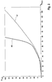
- Fig. 2 Exemplary relationships between the pressure P THZ in the master cylinder 12 and the associated actuating travel S pedal for the two operating modes Z A , Z P are shown schematically. Plotted is the pressure P THZ against the actuating travel S pedal , wherein characteristic curve 40 represents the first operating mode Z A and characteristic 41 the second operating mode Z P. Characteristic 40 or 41 represents the nominal relationship between the pressure P THZ and the actuating travel S Pedal in the respective operating mode Z A or Z P. According to the example, corresponding characteristic curves 40, 41 for the two operating modes 2 A , 2 P in the electronic Control unit 7 stored.
- the nominal pedal characteristic of the brake system in the first operating mode Z A ie the relationship between the pedal force and the pedal travel S pedal , is essentially determined by the simulator spring 21 (preferably a progressive compression spring, other spring elements are conceivable, eg an elastomer spring) of the pedal travel simulator 19.
- the displacement of the pedal travel simulator 19 depends linearly on the pedal travel S pedal .
- the pedal force and the pressure in the pedal travel simulator 19 are in a linear relationship.
- a characteristic curve 40 results which describes the pressure in the pedal travel simulator 19, which corresponds to the pressure P THZ measurable by means of the pressure sensor 15, as a function of the pedal travel S pedal .
- This nominal characteristic curve 40 which represents the normal brake function ("brake-by-wire" mode, first operating mode Z A ), is stored in the electronic control and regulation unit 7.
- the valves In the hydraulic fallback level (second operating mode Z P ), the valves, in particular the valves 14a, 14b, 20, 27a, 27b, are de-energized, and the driver is directly hydraulically connected to the wheel brakes 6 when the brake pedal 1 is actuated.
- the hydraulic design of the brake system and the vehicle-specific volume of the wheel brakes 6 thus results in a different pedal characteristic and the relationship between the measurable by pressure sensor 15 pressure P THZ and the pedal travel S pedal is described by curve 41.
- These nominal characteristic curve 41 which represents the second mode of operation Z P is stored in the electronic control and regulating unit. 7 How out Fig. 2 can be seen, the characteristics of the two operating modes Z P and Z A are significantly different.
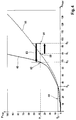
- FIG. 3 is a schematic flow diagram illustrating an example method of operation.
- FIG a brake system shown.
- the brake system is in a passive or deactivated state 50 (assuming no brake pedal actuation by the driver).
- the brake system is usually started, for example, by the driver by switching on the engine ignition or in advance by opening the driver's door (optionally by means of appropriate environmental sensors eg Keyless entry).
- an initialization of the sensors of the brake system for example the pressure sensors 15, 30, 31 and the position sensors 17, 24, is carried out in block 51 so that they provide measured values after the initialization.
- the corresponding valves for example the separating valves 14a, 14b, the simulator release valve 20 and the connection valves 27a, 27b, and the brake booster function are activated, so that in the case of actuation of the brake pedal by the driver a "brake-by-wire" Braking can be performed.
- the brake system is then in an operational active state (first operating mode Z A , block 65) in which the brake valves 1 actuated the isolation valves 14a, 14b of the actuator 2 closed, the Simulatorabigabeventil 20 and the Zuschaltventile 27a, 27b of the pressure supply device 4 is opened are.
- the driver is then not directly hydraulically connected to the brake circuits I, II and wheel brakes 6, but actuates the pedal travel simulator 19, while the brake circuits I, II by the pressure supply means 4 with the pressure P soll (according to a predetermined brake booster function) are acted upon.
- the initialization path without driver operation (blocks 50, 51, 52, 65) is generally the rule, ie the valves 14a, 14b, 20, 27a, 27b are energized directly and the printing device 4 is activated.
- the brake system is in the second operating mode Z P (fallback mode). If now the engine ignition is switched on (or the brake system is supplied with electrical energy again), then the brake system is converted according to the exemplary method described below in the first operating mode Z A (block 65), an advantage of the method is that the transfer as comfortable as possible and without irritation of the driver is performed.
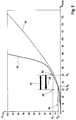
- the brake system is in the second operating mode Z P (fallback mode) and it is the characteristic 41 of the Fig. 4 effective.
- the Pedalweg S pedal and associated system pressure in the brake circuits I, II which corresponds to the pressure P THZ of the master cylinder 12 due to the open isolation valves 14a, 14b, according to the volume of the wheel brakes 6 and introduced via the driver pedal force to the point 80th (S 1 , P 1 ). If now the brake system, for example, by the driver by the engine ignition, started, then first in block 53 of the Fig.
- the position of the self-adjusting point 81 (S 2 , P 1 ) relative to the two nominal characteristic curves 40, 41 is determined in block 56 by a plausibility check or comparison using the current measured values of the sensors 15 and 17 (P THZ and S pedal ). as well as the characteristic curve 41 stored in block 54 for the second operating mode Z P and the characteristic curve 40 stored in block 55 for the second operating mode Z A. If it is detected in block 56 that the self-adjusting point 81 (S 2 , P 1 ) lies below the two nominal characteristic curves 40, 41, an active pedal correction, for example by means of the pressure supply device 4, is carried out (branch 57 to block 58).
- connection valves 27a, 27b are opened, so that the pressure supply device 4 is hydraulically connected to the brake circuits I, II, and thus also to the master cylinder 12.
- the pressure supply device 4 is further controlled such that pressure medium volume from the pressure supply device 4 via the open Zuschaltventile 27a, 27b and separating valves 14a, 14b is moved into the pressure chambers 10, 11 of the master cylinder 12, so that the brake pedal 1 against the acting pedal force the driver, ie constant pressure P 1 , is reset. Resetting the brake pedal 1 (the pad correction path) is in Fig. 4 represented by the arrow 83.
- Brake pedal 1 is set to the nominal point 82 of the characteristic curve 40 of the first operating mode Z A ("brake-by-wire" mode), so that the set pedal position to the resulting from the characteristic curve 40 pedal path S 3 for the (system) pressure P 1 corresponds.
- the pedal position is checked by means of the sensor 17.
- the brake system becomes fast, comfortable, and without irritating the driver during brake pedal operation transferred from the second operating mode in the first operating mode.
- the pedal correction corrects the brake system almost unnoticeably for the driver from the state of point 81 into the "brake-by-wire" operating state, which corresponds to point 82 on the driver's usual characteristic curve 40 of the first operating mode.
- the second case concerns the situation where the driver operates the brake pedal in the brake-by-wire mode, the brake system enters the fallback mode (eg due to a momentary power failure of the brake system), and then restarts or initializes the brake system while the driver stops on the brake pedal.
- Fig. 5 an exemplary diagram for the pedal travel S pedal and the associated pressure P THZ shown.
- the master cylinder 12 In the first operating mode, ie before switching to the hydraulic fallback level, the master cylinder 12 is connected to the pedal travel simulator 19 and it is the characteristic curve 40 of FIG Fig. 5 effective. According to the driver applied pedal force are thus the pressure P 2 on the master cylinder 12 and pedal travel 19 and the pedal travel S 4 before (point 84). In the brake circuits I, II there is a higher (system) pressure level due to the brake booster function of the pressure supply device 4.
- a plausibility check or a comparison based on the current measured values of the sensors 15 and 17 (P THZ and S pedal ) as well as the characteristic curves 41 and 40 stored in blocks 54 and 55, respectively, can be used to detect that the set value has changed Point 85 (S 5 , P 2 ) is above the nominal characteristic curves 40. If this is the case, then an active pedal correction, for example by means of the exhaust valves 29a-d, performed (branch 61 to block 62).
- the pedal correction in block 62 takes place, for example, by opening the exhaust valves 29a-d associated with the wheel brakes 6.
- the excess volume previously introduced via the wheel brakes 6 is discharged via the outlet valves 29a-d into the pressure medium reservoir 3 until the pedal travel of the brake pedal 1 again corresponds to the corresponding value S 4 of the nominal characteristic curve 40.
- the connection valves 27a, 27b are opened so that the pressure supply device 4 is connected to the brake circuits I, II.
- a pressure-displacement characteristic 42 of the pressure supply device 4 is stored in the control and regulation unit 7.
- An exemplary characteristic curve 42 for describing the relationship between piston position S piston and pressure P DBE of the pressure supply device 4 is shown in FIG Fig. 6 shown schematically.
- a check of the piston position S piston can be done by means of the sensor 24.
Landscapes
- Engineering & Computer Science (AREA)
- Transportation (AREA)
- Mechanical Engineering (AREA)
- Physics & Mathematics (AREA)
- Fluid Mechanics (AREA)
- Regulating Braking Force (AREA)
Claims (15)
- Procédé pour faire fonctionner un système de freinage pour véhicules automobiles, comprenant :• un maître-cylindre de frein (12) pouvant être actionné au moyen d'une pédale de frein (1), lequel est relié de manière séparable (14a, 14b) à au moins un circuit de frein (I, II) comprenant au moins un frein de roue (6) pouvant être actionné hydrauliquement, une première grandeur (PTHZ) caractérisant une pression dans le maître-cylindre de frein (12) et une deuxième grandeur (SPedal) caractérisant une course d'actionnement de la pédale de frein (1) étant mesurées au moins temporairement,• un simulateur de course de pédale (19) pouvant être actionné hydrauliquement, relié ou pouvant être relié au maître-cylindre de frein (12), lequel est réalisé pour pouvoir être mis en circuit et hors circuit au moyen d'une vanne de libération de simulateur (20),• un appareil de fourniture de pression (4) à commande électrique qui est relié de manière séparable (27a, 27b) au circuit de frein (I, II) et qui est notamment formé par un arrangement de cylindre-piston dont le piston (22) peut être actionné par un actionneur électromécanique (23), et• une unité de commande et de régulation électronique (7) destinée à commander l'appareil de fourniture de pression (4) à commande électrique ainsi que des vannes (20, 14a, 14b, 27a, 27b, 28a-d, 29a-d) du système de freinage,lors d'un actionnement de la pédale de frein (1), le circuit de frein (I, II) dans un premier mode de fonctionnement (ZA) étant chargé avec une pression (Psoll) de l'appareil de fourniture de pression (4) et, dans un deuxième mode de fonctionnement (ZP), étant chargé avec la pression (PTHZ) du maître-cylindre de frein (12),
caractérisé en ce que
lors d'un passage du deuxième mode de fonctionnement (ZP) au premier mode de fonctionnement (ZA) pendant un actionnement de la pédale de frein (1), la course d'actionnement (SPedal) de la pédale de frein (1) étant modifiée par commande ou régulation électronique. - Procédé selon la revendication 1, caractérisé en ce que lors du passage du deuxième mode de fonctionnement (ZP) au premier mode de fonctionnement (ZA) pendant un actionnement de la pédale de frein (1), la course d'actionnement (SPedal) de la pédale de frein (1) est modifiée par une évacuation à commande ou régulation électronique de fluide sous pression hors du maître-cylindre de frein (62) ou par acheminement à commande ou régulation électronique de fluide sous pression dans le maître-cylindre de frein (58).
- Procédé selon la revendication 1 ou 2, caractérisé en ce qu'une première courbe caractéristique (40), laquelle décrit une relation entre une première et une deuxième grandeur (PTHZ, SPedal) dans le premier mode de fonctionnement (ZA), et une deuxième courbe caractéristique (41), laquelle décrit une relation entre une première et une deuxième grandeur (PTHZ, SPedal) dans le deuxième mode de fonctionnement (ZP), sont prédéfinies, et qu'une décision d'évacuation ou d'acheminement de fluide sous pression est prise par le biais d'une comparaison des valeurs actuelles des première et deuxième grandeurs (PTHZ, SPedal) avec la première courbe caractéristique (40) et/ou la deuxième courbe caractéristique (41).
- Procédé selon la revendication 3, caractérisé en ce que la course d'actionnement (SPedal) est réduite par acheminement de fluide sous pression lorsque la paire de valeurs constituée des première et deuxième grandeurs (S2, P1) se trouve au-dessus de la deuxième courbe caractéristique (41) après une mise en circuit du simulateur de course de pédale (19).
- Procédé selon la revendication 3 ou 4, caractérisé en ce que la course d'actionnement (SPedal) est agrandie par évacuation de fluide sous pression lorsque la paire de valeurs constituée des première et deuxième grandeurs (S5, P2) se trouve au-dessus de la première courbe caractéristique (40) après une mise en circuit du simulateur de course de pédale.
- Procédé selon l'une des revendications 3 à 5, caractérisé en ce que la course d'actionnement (SPedal) est modifiée à une valeur (S3, S4) conformément à la première courbe caractéristique (40).
- Procédé selon l'une des revendications précédentes, caractérisé en ce que lors du passage du deuxième mode de fonctionnement (ZP) au premier mode de fonctionnement (ZA), les capteurs (15, 17) destinés à mesurer les première et deuxième grandeurs (PTHZ, SPedal) sont tout d'abord initialisés et le simulateur de course de pédale est ensuite connecté (53) au moyen de la vanne de libération de simulateur (20), et notamment en ce que la modification de la course d'actionnement (SPedal) de la pédale de frein (1) est effectuée ensuite.
- Procédé selon l'une des revendications précédentes, caractérisé en ce que la course d'actionnement (SPedal) de la pédale de frein (1) est réduite (58) en ce qu'une vanne de mise en circuit (27a, 27b) disposée entre l'appareil de fourniture de pression (4) et le circuit de frein (I, II) est ouverte et l'appareil de fourniture de pression (4) est commandé de telle sorte que le volume de fluide sous pression est déplacé dans le maître-cylindre de frein (12).
- Procédé selon l'une des revendications précédentes, caractérisé en ce que la course d'actionnement (SPedal) de la pédale de frein (1) est agrandie (62) en ce qu'une vanne d'évacuation (29a, 29b) disposée entre un frein de roue (6) et un réservoir à fluide sous pression (3) est ouverte.
- Procédé selon la revendication 9, caractérisé en ce qu'une vanne de mise en circuit (27a, 27b) disposée entre l'appareil de fourniture de pression (4) et le circuit de frein (I, II) est ouverte en plus, notamment simultanément.
- Procédé selon la revendication 10, caractérisé en ce que l'appareil de fourniture de pression (4) est formé par un arrangement de cylindre-piston dont le piston (22) peut être actionné par un actionneur électromécanique (23), et en ce qu'en plus, notamment simultanément, le piston (22) de l'appareil de fourniture de pression (4) est réglé à une position de piston (SK1) prédéterminée, notamment conformément à une courbe caractéristique prédéfinie de la position du piston en fonction de la pression (42).
- Procédé selon l'une des revendications précédentes, caractérisé en ce qu'après la modification de la course d'actionnement (SPedal) de la pédale de frein (1), une vanne de séparation (14a, 14b) disposée entre le maître-cylindre de frein (12) et le circuit de frein (I, II) est fermée (59) et, ensuite, une pression de consigne (Psoll) prédéterminée est réglée par l'appareil de fourniture de pression (4), laquelle est déterminée notamment au moyen des valeurs actuelles des première et deuxième grandeurs (PTHZ, SPedal).
- Procédé selon l'une des revendications précédentes, caractérisé en ce que lors du passage, aucune modification de la course d'actionnement (SPedal) de la pédale de frein (1) n'est effectuée si la valeur actuelle de la deuxième grandeur (SPedal) est inférieure à une première valeur de seuil (Sg) prédéfinie et notamment si, en plus de cela, la valeur actuelle de la première grandeur (PTHZ) est inférieure à une deuxième valeur de seuil (Pg) prédéfinie.
- Système de freinage pour véhicules automobiles, comprenant :• un maître-cylindre de frein (12) pouvant être actionné au moyen d'une pédale de frein (1), lequel est relié de manière séparable (14a, 14b) à au moins un circuit de frein (I, II) comprenant au moins un frein de roue (6) pouvant être actionné hydrauliquement,• un dispositif de mesure (15) destiné à déterminer une première grandeur (PTHZ) caractérisant une pression dans le maître-cylindre de frein (12) et un dispositif de mesure (17) destiné à déterminer une deuxième grandeur (SPedal) caractérisant une course d'actionnement de la pédale de frein (1),• un simulateur de course de pédale (19) pouvant être actionné hydrauliquement, relié ou pouvant être relié au maître-cylindre de frein (12), lequel est réalisé pour pouvoir être mis en circuit et hors circuit au moyen d'une vanne de libération de simulateur (20),• un appareil de fourniture de pression (4) à commande électrique qui est relié de manière séparable (27a, 27b) au circuit de frein (I, II) et qui est notamment formé par un arrangement de cylindre-piston dont le piston (22) peut être actionné par un actionneur électromécanique (23),• notamment une unité de modulation de pression de frein de roue (5) qui possède, pour chaque frein de roue (6), une vanne d'entrée (28a-d) ainsi qu'une vanne d'évacuation (29a-d) servant au réglage d'une pression de freinage individuelle de roue, laquelle est dérivée de la pression dans le circuit de frein (I, II), et• une unité de commande et de régulation électronique (7) destinée à commander l'appareil de fourniture de pression (4) à commande électrique ainsi que les vannes (20, 14a, 14b, 27a, 27b, 28a-d, 29a-d) du système de freinage,dans un premier mode de fonctionnement (ZA), lors d'un actionnement de la pédale de frein (1), le circuit de frein (I, II) étant chargé avec une pression (Psoll) de l'appareil de fourniture de pression (4) et, dans un deuxième mode de fonctionnement (ZP), lors d'un actionnement de la pédale de frein (1), le circuit de frein (I, II) étant chargé avec la pression (PTHZ) du maître-cylindre de frein (12),
caractérisé en ce que
l'unité de commande et de régulation (7), lors d'un passage du deuxième mode de fonctionnement (ZP) au premier mode de fonctionnement (ZA) pendant un actionnement de la pédale de frein (1), effectue une modification de la course d'actionnement (SPedal) de la pédale de frein (1). - Système de freinage équipé d'une unité de commande et de régulation électronique (7), notamment selon la revendication 14, caractérisé en ce qu'un procédé selon l'une des revendications 1 à 13 est mis en oeuvre dans l'unité de commande et de régulation électronique (7).
Applications Claiming Priority (2)
| Application Number | Priority Date | Filing Date | Title |
|---|---|---|---|
| DE201210201515 DE102012201515A1 (de) | 2012-02-02 | 2012-02-02 | Verfahren zum Betrieb einer Bremsanlage für Kraftfahrzeuge sowie Bremsanlage |
| PCT/EP2013/051436 WO2013113625A1 (fr) | 2012-02-02 | 2013-01-25 | Procede pour faire fonctionner un systeme de freinage de vehicules à moteur et systeme de freinage |
Publications (2)
| Publication Number | Publication Date |
|---|---|
| EP2809559A1 EP2809559A1 (fr) | 2014-12-10 |
| EP2809559B1 true EP2809559B1 (fr) | 2016-04-06 |
Family
ID=47603773
Family Applications (1)
| Application Number | Title | Priority Date | Filing Date |
|---|---|---|---|
| EP13701110.2A Not-in-force EP2809559B1 (fr) | 2012-02-02 | 2013-01-25 | Procede pour faire fonctionner un systeme de freinage de vehicules à moteur et systeme de freinage |
Country Status (6)
| Country | Link |
|---|---|
| US (1) | US9108604B2 (fr) |
| EP (1) | EP2809559B1 (fr) |
| KR (1) | KR102001707B1 (fr) |
| CN (1) | CN104105626B (fr) |
| DE (1) | DE102012201515A1 (fr) |
| WO (1) | WO2013113625A1 (fr) |
Families Citing this family (33)
| Publication number | Priority date | Publication date | Assignee | Title |
|---|---|---|---|---|
| DE102012222897A1 (de) * | 2012-02-28 | 2013-08-29 | Continental Teves Ag & Co. Ohg | Verfahren zum Betrieb einer Bremsanlage |
| DE102012025291A1 (de) * | 2012-12-21 | 2014-06-26 | Lucas Automotive Gmbh | Elektrohydraulische Fahrzeug-Bremsanlage und Verfahren zum Betreiben derselben |
| DE102013224313A1 (de) * | 2013-03-05 | 2014-09-11 | Continental Teves Ag & Co. Ohg | Verfahren zum Betreiben eines Bremssystems |
| DE102013222061A1 (de) * | 2013-03-25 | 2014-09-25 | Continental Teves Ag & Co. Ohg | Verfahren zum Betrieb einer Bremsanlage für Kraftfahrzeuge |
| DE102013222281A1 (de) * | 2013-05-02 | 2014-11-06 | Continental Teves Ag & Co. Ohg | Verfahren zur haptischen Information eines Fahrers eines Kraftfahrzeugs und Bremsanlage |
| KR102255792B1 (ko) * | 2014-06-26 | 2021-05-27 | 주식회사 만도 | 페달감 모사 장치 |
| JP6361046B2 (ja) * | 2014-12-12 | 2018-07-25 | 日立オートモティブシステムズ株式会社 | ブレーキ装置及びブレーキシステム |
| DE102014225954A1 (de) * | 2014-12-16 | 2016-06-16 | Continental Teves Ag & Co. Ohg | Bremsensteuervorrichtung sowie Bremsanlage |
| DE102015201331A1 (de) * | 2015-01-27 | 2016-07-28 | Continental Teves Ag & Co. Ohg | Verfahren zum Betrieb einer Bremsanlage sowie Bremsanlage |
| EP3271227B1 (fr) | 2015-03-16 | 2021-10-20 | Ipgate Ag | Système de freinage équipé d'une unité à maître-cylindre de frein à régulation mux innovante (mux 2.0) comprenant au moins une soupape de sortie, et procédé servant à la régulation de pression |
| KR20170128531A (ko) | 2015-03-16 | 2017-11-22 | 이페게이트 아게 | 출구 밸브를 갖는 신규한 mux 조절(mux 2.0)을 갖는 브레이크 시스템/브레이크 회로마다의 브레이크 시스템 또는 출구 밸브, 및 압력 제어를 위한 방법 |
| WO2016146118A1 (fr) * | 2015-03-17 | 2016-09-22 | Schaeffler Technologies AG & Co. KG | Procédé d'adaptation d'un point de contact d'un embrayage fermé à l'état non actionné |
| DE102015219001A1 (de) * | 2015-10-01 | 2017-04-06 | Continental Teves Ag & Co. Ohg | Bremssystem und Verfahren zum Betreiben eines Bremssystems |
| KR102473927B1 (ko) * | 2015-10-19 | 2022-12-06 | 에이치엘만도 주식회사 | 전자식 브레이크 시스템의 진단방법 |
| JP6512148B2 (ja) * | 2016-03-25 | 2019-05-15 | 株式会社アドヴィックス | 車両用制動装置 |
| US10300901B2 (en) * | 2016-05-26 | 2019-05-28 | Fca Us Llc | Validation of brake torque signal for use as a brake event |
| DE102016217439B4 (de) | 2016-09-13 | 2021-12-23 | Audi Ag | Verfahren und Vorrichtung zum Einstellen einer Nulllage eines Bremspedals |
| DE102017200420A1 (de) | 2017-01-12 | 2018-07-12 | Continental Teves Ag & Co. Ohg | Verfahren zum Betreiben einer Bremsanlage und Bremsanlage |
| DE102017202361A1 (de) * | 2017-02-15 | 2018-08-16 | Continental Teves Ag & Co. Ohg | Verfahren zum Betreiben einer Bremsanlage und Bremsanlage |
| DE102017002770A1 (de) | 2017-03-22 | 2018-09-27 | Lucas Automotive Gmbh | Pedalsimulationsvorrichtung mit mehreren Rückstellelementen |
| DE102017113563A1 (de) | 2017-06-20 | 2018-12-20 | Ipgate Ag | Bremssystem |
| DE102017213392A1 (de) * | 2017-08-02 | 2019-02-07 | Robert Bosch Gmbh | Steuervorrichtung und Verfahren zum Betreiben eines Simulator-bestückten hydraulischen Bremssystems eines Fahrzeugs |
| DE102017009654A1 (de) * | 2017-10-17 | 2019-04-18 | Wabco Gmbh | Bremsventil, Druckluft-Bremssystem mit dem Bremsventil und Verfahren zur Herstellung des Bremsventils |
| US10620078B2 (en) * | 2017-11-17 | 2020-04-14 | Robert Bosch Gmbh | Performing a diagnostic on a hydraulic system while the vehicle is operating |
| DE102018212290A1 (de) | 2018-07-24 | 2020-01-30 | Robert Bosch Gmbh | Verfahren zum Betreiben eines Bremssystems sowie Bremssystem |
| KR102635286B1 (ko) * | 2019-03-11 | 2024-02-08 | 에이치엘만도 주식회사 | 전자식 브레이크 시스템 |
| DE102019206612B3 (de) * | 2019-05-08 | 2020-07-16 | Volkswagen Aktiengesellschaft | Verfahren zur Steuerung eines elektromechanischen Bremssystems sowie elektromechanisches Bremssystem |
| DE102019207284A1 (de) * | 2019-05-18 | 2020-11-19 | Robert Bosch Gmbh | Verfahren und Vorrichtung zum Betreiben eines Bremssystems eines Kraftfahrzeugs, Bremssystem und Kraftfahrzeug |
| KR102179663B1 (ko) * | 2019-08-22 | 2020-11-17 | 현대모비스 주식회사 | 차고 조절 장치 및 방법 |
| DE102019215360A1 (de) * | 2019-10-08 | 2021-04-08 | Continental Teves Ag & Co. Ohg | Verfahren zum Betreiben eines Bremssystems, Bremssystem, Kraftfahrzeug und Speichermedium |
| IT201900025336A1 (it) * | 2019-12-23 | 2021-06-23 | Freni Brembo Spa | Un impianto frenante per veicoli con pedale di azionamento collassabile e il relativo metodo di azionamento di un impianto di frenatura in caso di urto |
| CN114516317B (zh) * | 2020-11-19 | 2024-06-21 | 大陆泰密克汽车系统(上海)有限公司 | 电子液压制动系统及其运行方法和机动车 |
| DE102022108721A1 (de) | 2022-04-11 | 2023-10-12 | Heinz Leiber | Hauptbremszylinder mit regelbarer Pedalcharakteristik |
Family Cites Families (24)
| Publication number | Priority date | Publication date | Assignee | Title |
|---|---|---|---|---|
| JP3851043B2 (ja) * | 1999-12-24 | 2006-11-29 | トヨタ自動車株式会社 | ブレーキ液圧制御装置 |
| US6957870B2 (en) * | 1999-12-24 | 2005-10-25 | Toyota Jidosha Kabushiki Kaisha | Braking pressure control apparatus capable of switching between two brake operating states using power-operated and manually operated pressure sources, respectively |
| JP2001180464A (ja) | 1999-12-24 | 2001-07-03 | Toyota Motor Corp | ブレーキ液圧制御装置 |
| DE10114599A1 (de) * | 2000-03-27 | 2001-12-06 | Continental Teves Ag & Co Ohg | Verfahren zur Regelung einer Bremsanlage für Kraftfahrzeuge |
| JP3941388B2 (ja) * | 2000-12-21 | 2007-07-04 | トヨタ自動車株式会社 | 車輌の制動制御装置 |
| JP4196540B2 (ja) * | 2001-01-16 | 2008-12-17 | トヨタ自動車株式会社 | ブレーキ装置 |
| JP4446232B2 (ja) * | 2004-01-27 | 2010-04-07 | 株式会社アドヴィックス | 車両用制動装置 |
| JP2007038698A (ja) * | 2005-07-29 | 2007-02-15 | Toyota Motor Corp | 車両用制動装置 |
| JP2007069649A (ja) | 2005-09-05 | 2007-03-22 | Honda Motor Co Ltd | ブレーキ・バイ・ワイヤ装置 |
| KR100990069B1 (ko) * | 2005-12-07 | 2010-10-29 | 주식회사 만도 | 전자 유압 브레이크 시스템 |
| DE102006059949A1 (de) * | 2006-02-23 | 2007-12-06 | Continental Teves Ag & Co. Ohg | Verfahren zum Betreiben einer Kraftfahrzeugbremsanlage |
| DE102006014836A1 (de) * | 2006-03-30 | 2007-10-04 | Lucas Automotive Gmbh | Elektrohydraulische Bremsanlage |
| JP4215074B2 (ja) * | 2006-06-28 | 2009-01-28 | トヨタ自動車株式会社 | ブレーキ制御装置及びブレーキ制御方法 |
| DE102006040424A1 (de) * | 2006-08-29 | 2008-03-06 | Continental Teves Ag & Co. Ohg | Bremssystem für Kraftfahrzeuge |
| JP4297151B2 (ja) * | 2006-10-05 | 2009-07-15 | トヨタ自動車株式会社 | ブレーキ制御装置 |
| DE102007059734B4 (de) * | 2006-12-21 | 2016-12-08 | Toyota Jidosha Kabushiki Kaisha | Bremsregelungsvorrichtung und Bremsregelungsverfahren |
| JP4974685B2 (ja) * | 2007-01-16 | 2012-07-11 | 本田技研工業株式会社 | ブレーキ装置 |
| DE102009033499A1 (de) * | 2008-07-18 | 2010-01-21 | Continental Teves Ag & Co. Ohg | Bremsanlage für Kraftfahrzeuge |
| DE102010040097A1 (de) | 2009-09-11 | 2011-03-31 | Continental Teves Ag & Co. Ohg | Bremsanlage für Kraftfahrzeuge |
| DE102010001941A1 (de) * | 2010-02-15 | 2011-08-18 | Robert Bosch GmbH, 70469 | Verfahren zum Betreiben eines bremskraftverstärkten hydraulischen Bremssystems eines Fahrzeugs und Steuervorrichtung für ein bremskraftverstärktes hydraulisches Bremssystem eines Fahrzeugs |
| DE102011081461A1 (de) * | 2010-08-30 | 2012-03-01 | Continental Teves Ag & Co. Ohg | Bremsanlage für Kraftfahrzeuge |
| DE102012205862A1 (de) * | 2011-04-19 | 2012-10-25 | Continental Teves Ag & Co. Ohg | Bremsanlage für Kraftfahrzeuge sowie Verfahren zum Betrieb einer Bremsanlage |
| DE102012205860A1 (de) * | 2011-04-19 | 2012-10-25 | Continental Teves Ag & Co. Ohg | Bremsanlage für Kraftfahrzeuge |
| DE102012202645A1 (de) * | 2011-04-28 | 2012-10-31 | Continental Teves Ag & Co. Ohg | Bremsanlage für Kraftfahrzeuge |
-
2012
- 2012-02-02 DE DE201210201515 patent/DE102012201515A1/de not_active Withdrawn
-
2013
- 2013-01-25 KR KR1020147024538A patent/KR102001707B1/ko active IP Right Grant
- 2013-01-25 WO PCT/EP2013/051436 patent/WO2013113625A1/fr active Application Filing
- 2013-01-25 CN CN201380007518.1A patent/CN104105626B/zh not_active Expired - Fee Related
- 2013-01-25 EP EP13701110.2A patent/EP2809559B1/fr not_active Not-in-force
- 2013-01-25 US US14/374,370 patent/US9108604B2/en not_active Expired - Fee Related
Also Published As
| Publication number | Publication date |
|---|---|
| WO2013113625A1 (fr) | 2013-08-08 |
| CN104105626B (zh) | 2017-01-18 |
| DE102012201515A1 (de) | 2013-08-08 |
| CN104105626A (zh) | 2014-10-15 |
| KR20140128401A (ko) | 2014-11-05 |
| EP2809559A1 (fr) | 2014-12-10 |
| KR102001707B1 (ko) | 2019-07-18 |
| US20140368027A1 (en) | 2014-12-18 |
| US9108604B2 (en) | 2015-08-18 |
Similar Documents
| Publication | Publication Date | Title |
|---|---|---|
| EP2809559B1 (fr) | Procede pour faire fonctionner un systeme de freinage de vehicules à moteur et systeme de freinage | |
| EP3271227B1 (fr) | Système de freinage équipé d'une unité à maître-cylindre de frein à régulation mux innovante (mux 2.0) comprenant au moins une soupape de sortie, et procédé servant à la régulation de pression | |
| DE112015003240B4 (de) | Betätigungssystem, insbesondere für eine Fahrzeugbremse und Verfahren zum Betrieb des Betätigungssystems | |
| EP2822824B1 (fr) | Procede de fonctionnement d'un systeme de freinage de vehicules automobiles, et systeme de freinage | |
| DE102013203599B4 (de) | Verfahren zur Kalibrierung von analog angesteuerten hydraulischen Ventilen und eine Bremsanlage | |
| DE102013203189A1 (de) | Verfahren zur Bestimmung einer Druck-Volumen-Kennlinie einer Radbremse | |
| DE102009055721A1 (de) | Bremssystem mit Speichereinrichtung mit Mehrfachfunktion | |
| WO2015036601A2 (fr) | Dispositif de freinage et procédé pour faire fonctionner un dispositif de freinage | |
| DE102015201331A1 (de) | Verfahren zum Betrieb einer Bremsanlage sowie Bremsanlage | |
| DE102020202368A1 (de) | Verfahren zum Betreiben eines Bremssystems und Bremssystem | |
| DE102016202224A1 (de) | Verfahren zum Betreiben einer Bremsanlage eines Fahrzeuges und Bremsanlage | |
| EP1646543A1 (fr) | Systeme de freinage electro-hydraulique pour automobiles | |
| DE102018206586A1 (de) | Verfahren zum Betreiben eines Fahrzeuges mit einem elektrohydraulischen Bremssystem sowie elektrohydraulisches Bremssystem eines Fahrzeuges | |
| EP1989088B1 (fr) | Procede de gestion d'un système de freinage pour véhicule automobile | |
| WO2011012346A1 (fr) | Installation hydraulique de freinage pour véhicule, véhicule doté de cette installation de freinage et procédé de conduite d'une installation hydraulique de freinage pour véhicule | |
| EP4297998A1 (fr) | Procédé de freinage d'un véhicule et système de freinage | |
| DE102016208564B4 (de) | Verfahren zum Betreiben einer Bremsanlage mit einer Druckbereitstellungseinrichtung und Bremsanlage | |
| DE102014224205A1 (de) | Verfahren zum Betrieb einer Bremsanlage sowie Bremsanlage | |
| DE102014215379B4 (de) | Bremssystem für ein Fahrzeug | |
| DE102017211807A1 (de) | Bremssystem mit primärer Bremsregeleinrichtung und Zusatzmodul | |
| WO2021063577A1 (fr) | Procédé de commande d'un système de freinage assisté externe à régulation électronique de patinage, en particulier pour un véhicule automobile, et système de freinage assisté externe à régulation électronique de patinage, en particulier pour un véhicule automobile | |
| WO2007138012A1 (fr) | Unité d'actionnement de frein | |
| DE102006056907A1 (de) | Bremsbetätigungseinheit | |
| DE102012210434A1 (de) | Verfahren zum Betrieb einer Bremsanlage für Kraftfahrzeuge sowie Bremsanlage | |
| DE102012221346A1 (de) | Bremsanlage für Kraftfahrzeuge |
Legal Events
| Date | Code | Title | Description |
|---|---|---|---|
| PUAI | Public reference made under article 153(3) epc to a published international application that has entered the european phase |
Free format text: ORIGINAL CODE: 0009012 |
|
| 17P | Request for examination filed |
Effective date: 20140902 |
|
| AK | Designated contracting states |
Kind code of ref document: A1 Designated state(s): AL AT BE BG CH CY CZ DE DK EE ES FI FR GB GR HR HU IE IS IT LI LT LU LV MC MK MT NL NO PL PT RO RS SE SI SK SM TR |
|
| AX | Request for extension of the european patent |
Extension state: BA ME |
|
| DAX | Request for extension of the european patent (deleted) | ||
| GRAP | Despatch of communication of intention to grant a patent |
Free format text: ORIGINAL CODE: EPIDOSNIGR1 |
|
| INTG | Intention to grant announced |
Effective date: 20151009 |
|
| GRAS | Grant fee paid |
Free format text: ORIGINAL CODE: EPIDOSNIGR3 |
|
| GRAA | (expected) grant |
Free format text: ORIGINAL CODE: 0009210 |
|
| AK | Designated contracting states |
Kind code of ref document: B1 Designated state(s): AL AT BE BG CH CY CZ DE DK EE ES FI FR GB GR HR HU IE IS IT LI LT LU LV MC MK MT NL NO PL PT RO RS SE SI SK SM TR |
|
| REG | Reference to a national code |
Ref country code: GB Ref legal event code: FG4D Free format text: NOT ENGLISH |
|
| REG | Reference to a national code |
Ref country code: AT Ref legal event code: REF Ref document number: 787426 Country of ref document: AT Kind code of ref document: T Effective date: 20160415 Ref country code: CH Ref legal event code: EP |
|
| REG | Reference to a national code |
Ref country code: IE Ref legal event code: FG4D Free format text: LANGUAGE OF EP DOCUMENT: GERMAN |
|
| REG | Reference to a national code |
Ref country code: DE Ref legal event code: R096 Ref document number: 502013002456 Country of ref document: DE |
|
| REG | Reference to a national code |
Ref country code: LT Ref legal event code: MG4D Ref country code: NL Ref legal event code: MP Effective date: 20160406 |
|
| PG25 | Lapsed in a contracting state [announced via postgrant information from national office to epo] |
Ref country code: NL Free format text: LAPSE BECAUSE OF FAILURE TO SUBMIT A TRANSLATION OF THE DESCRIPTION OR TO PAY THE FEE WITHIN THE PRESCRIBED TIME-LIMIT Effective date: 20160406 |
|
| PG25 | Lapsed in a contracting state [announced via postgrant information from national office to epo] |
Ref country code: IS Free format text: LAPSE BECAUSE OF FAILURE TO SUBMIT A TRANSLATION OF THE DESCRIPTION OR TO PAY THE FEE WITHIN THE PRESCRIBED TIME-LIMIT Effective date: 20160806 Ref country code: PL Free format text: LAPSE BECAUSE OF FAILURE TO SUBMIT A TRANSLATION OF THE DESCRIPTION OR TO PAY THE FEE WITHIN THE PRESCRIBED TIME-LIMIT Effective date: 20160406 Ref country code: LT Free format text: LAPSE BECAUSE OF FAILURE TO SUBMIT A TRANSLATION OF THE DESCRIPTION OR TO PAY THE FEE WITHIN THE PRESCRIBED TIME-LIMIT Effective date: 20160406 Ref country code: FI Free format text: LAPSE BECAUSE OF FAILURE TO SUBMIT A TRANSLATION OF THE DESCRIPTION OR TO PAY THE FEE WITHIN THE PRESCRIBED TIME-LIMIT Effective date: 20160406 Ref country code: NO Free format text: LAPSE BECAUSE OF FAILURE TO SUBMIT A TRANSLATION OF THE DESCRIPTION OR TO PAY THE FEE WITHIN THE PRESCRIBED TIME-LIMIT Effective date: 20160706 |
|
| PG25 | Lapsed in a contracting state [announced via postgrant information from national office to epo] |
Ref country code: ES Free format text: LAPSE BECAUSE OF FAILURE TO SUBMIT A TRANSLATION OF THE DESCRIPTION OR TO PAY THE FEE WITHIN THE PRESCRIBED TIME-LIMIT Effective date: 20160406 Ref country code: LV Free format text: LAPSE BECAUSE OF FAILURE TO SUBMIT A TRANSLATION OF THE DESCRIPTION OR TO PAY THE FEE WITHIN THE PRESCRIBED TIME-LIMIT Effective date: 20160406 Ref country code: SE Free format text: LAPSE BECAUSE OF FAILURE TO SUBMIT A TRANSLATION OF THE DESCRIPTION OR TO PAY THE FEE WITHIN THE PRESCRIBED TIME-LIMIT Effective date: 20160406 Ref country code: PT Free format text: LAPSE BECAUSE OF FAILURE TO SUBMIT A TRANSLATION OF THE DESCRIPTION OR TO PAY THE FEE WITHIN THE PRESCRIBED TIME-LIMIT Effective date: 20160808 Ref country code: RS Free format text: LAPSE BECAUSE OF FAILURE TO SUBMIT A TRANSLATION OF THE DESCRIPTION OR TO PAY THE FEE WITHIN THE PRESCRIBED TIME-LIMIT Effective date: 20160406 Ref country code: GR Free format text: LAPSE BECAUSE OF FAILURE TO SUBMIT A TRANSLATION OF THE DESCRIPTION OR TO PAY THE FEE WITHIN THE PRESCRIBED TIME-LIMIT Effective date: 20160707 Ref country code: HR Free format text: LAPSE BECAUSE OF FAILURE TO SUBMIT A TRANSLATION OF THE DESCRIPTION OR TO PAY THE FEE WITHIN THE PRESCRIBED TIME-LIMIT Effective date: 20160406 |
|
| PG25 | Lapsed in a contracting state [announced via postgrant information from national office to epo] |
Ref country code: IT Free format text: LAPSE BECAUSE OF FAILURE TO SUBMIT A TRANSLATION OF THE DESCRIPTION OR TO PAY THE FEE WITHIN THE PRESCRIBED TIME-LIMIT Effective date: 20160406 |
|
| REG | Reference to a national code |
Ref country code: DE Ref legal event code: R097 Ref document number: 502013002456 Country of ref document: DE |
|
| PG25 | Lapsed in a contracting state [announced via postgrant information from national office to epo] |
Ref country code: CZ Free format text: LAPSE BECAUSE OF FAILURE TO SUBMIT A TRANSLATION OF THE DESCRIPTION OR TO PAY THE FEE WITHIN THE PRESCRIBED TIME-LIMIT Effective date: 20160406 Ref country code: EE Free format text: LAPSE BECAUSE OF FAILURE TO SUBMIT A TRANSLATION OF THE DESCRIPTION OR TO PAY THE FEE WITHIN THE PRESCRIBED TIME-LIMIT Effective date: 20160406 Ref country code: SK Free format text: LAPSE BECAUSE OF FAILURE TO SUBMIT A TRANSLATION OF THE DESCRIPTION OR TO PAY THE FEE WITHIN THE PRESCRIBED TIME-LIMIT Effective date: 20160406 Ref country code: RO Free format text: LAPSE BECAUSE OF FAILURE TO SUBMIT A TRANSLATION OF THE DESCRIPTION OR TO PAY THE FEE WITHIN THE PRESCRIBED TIME-LIMIT Effective date: 20160406 Ref country code: DK Free format text: LAPSE BECAUSE OF FAILURE TO SUBMIT A TRANSLATION OF THE DESCRIPTION OR TO PAY THE FEE WITHIN THE PRESCRIBED TIME-LIMIT Effective date: 20160406 |
|
| PLBE | No opposition filed within time limit |
Free format text: ORIGINAL CODE: 0009261 |
|
| STAA | Information on the status of an ep patent application or granted ep patent |
Free format text: STATUS: NO OPPOSITION FILED WITHIN TIME LIMIT |
|
| PG25 | Lapsed in a contracting state [announced via postgrant information from national office to epo] |
Ref country code: SM Free format text: LAPSE BECAUSE OF FAILURE TO SUBMIT A TRANSLATION OF THE DESCRIPTION OR TO PAY THE FEE WITHIN THE PRESCRIBED TIME-LIMIT Effective date: 20160406 |
|
| 26N | No opposition filed |
Effective date: 20170110 |
|
| PG25 | Lapsed in a contracting state [announced via postgrant information from national office to epo] |
Ref country code: BE Free format text: LAPSE BECAUSE OF NON-PAYMENT OF DUE FEES Effective date: 20170131 Ref country code: SI Free format text: LAPSE BECAUSE OF FAILURE TO SUBMIT A TRANSLATION OF THE DESCRIPTION OR TO PAY THE FEE WITHIN THE PRESCRIBED TIME-LIMIT Effective date: 20160406 |
|
| REG | Reference to a national code |
Ref country code: CH Ref legal event code: PL |
|
| GBPC | Gb: european patent ceased through non-payment of renewal fee |
Effective date: 20170125 |
|
| PG25 | Lapsed in a contracting state [announced via postgrant information from national office to epo] |
Ref country code: MC Free format text: LAPSE BECAUSE OF FAILURE TO SUBMIT A TRANSLATION OF THE DESCRIPTION OR TO PAY THE FEE WITHIN THE PRESCRIBED TIME-LIMIT Effective date: 20160406 |
|
| REG | Reference to a national code |
Ref country code: FR Ref legal event code: ST Effective date: 20170929 |
|
| PG25 | Lapsed in a contracting state [announced via postgrant information from national office to epo] |
Ref country code: FR Free format text: LAPSE BECAUSE OF NON-PAYMENT OF DUE FEES Effective date: 20170131 Ref country code: LI Free format text: LAPSE BECAUSE OF NON-PAYMENT OF DUE FEES Effective date: 20170131 Ref country code: CH Free format text: LAPSE BECAUSE OF NON-PAYMENT OF DUE FEES Effective date: 20170131 |
|
| REG | Reference to a national code |
Ref country code: IE Ref legal event code: MM4A |
|
| PG25 | Lapsed in a contracting state [announced via postgrant information from national office to epo] |
Ref country code: GB Free format text: LAPSE BECAUSE OF NON-PAYMENT OF DUE FEES Effective date: 20170125 Ref country code: LU Free format text: LAPSE BECAUSE OF NON-PAYMENT OF DUE FEES Effective date: 20170125 |
|
| REG | Reference to a national code |
Ref country code: BE Ref legal event code: MM Effective date: 20170131 |
|
| PG25 | Lapsed in a contracting state [announced via postgrant information from national office to epo] |
Ref country code: IE Free format text: LAPSE BECAUSE OF NON-PAYMENT OF DUE FEES Effective date: 20170125 |
|
| PG25 | Lapsed in a contracting state [announced via postgrant information from national office to epo] |
Ref country code: MT Free format text: LAPSE BECAUSE OF FAILURE TO SUBMIT A TRANSLATION OF THE DESCRIPTION OR TO PAY THE FEE WITHIN THE PRESCRIBED TIME-LIMIT Effective date: 20160406 |
|
| PG25 | Lapsed in a contracting state [announced via postgrant information from national office to epo] |
Ref country code: AL Free format text: LAPSE BECAUSE OF FAILURE TO SUBMIT A TRANSLATION OF THE DESCRIPTION OR TO PAY THE FEE WITHIN THE PRESCRIBED TIME-LIMIT Effective date: 20160406 |
|
| REG | Reference to a national code |
Ref country code: AT Ref legal event code: MM01 Ref document number: 787426 Country of ref document: AT Kind code of ref document: T Effective date: 20180125 |
|
| PG25 | Lapsed in a contracting state [announced via postgrant information from national office to epo] |
Ref country code: AT Free format text: LAPSE BECAUSE OF NON-PAYMENT OF DUE FEES Effective date: 20180125 |
|
| PG25 | Lapsed in a contracting state [announced via postgrant information from national office to epo] |
Ref country code: HU Free format text: LAPSE BECAUSE OF FAILURE TO SUBMIT A TRANSLATION OF THE DESCRIPTION OR TO PAY THE FEE WITHIN THE PRESCRIBED TIME-LIMIT; INVALID AB INITIO Effective date: 20130125 |
|
| PG25 | Lapsed in a contracting state [announced via postgrant information from national office to epo] |
Ref country code: BG Free format text: LAPSE BECAUSE OF FAILURE TO SUBMIT A TRANSLATION OF THE DESCRIPTION OR TO PAY THE FEE WITHIN THE PRESCRIBED TIME-LIMIT Effective date: 20160406 |
|
| PG25 | Lapsed in a contracting state [announced via postgrant information from national office to epo] |
Ref country code: CY Free format text: LAPSE BECAUSE OF FAILURE TO SUBMIT A TRANSLATION OF THE DESCRIPTION OR TO PAY THE FEE WITHIN THE PRESCRIBED TIME-LIMIT Effective date: 20160406 |
|
| PG25 | Lapsed in a contracting state [announced via postgrant information from national office to epo] |
Ref country code: MK Free format text: LAPSE BECAUSE OF FAILURE TO SUBMIT A TRANSLATION OF THE DESCRIPTION OR TO PAY THE FEE WITHIN THE PRESCRIBED TIME-LIMIT Effective date: 20160406 |
|
| PG25 | Lapsed in a contracting state [announced via postgrant information from national office to epo] |
Ref country code: TR Free format text: LAPSE BECAUSE OF FAILURE TO SUBMIT A TRANSLATION OF THE DESCRIPTION OR TO PAY THE FEE WITHIN THE PRESCRIBED TIME-LIMIT Effective date: 20160406 |
|
| PGFP | Annual fee paid to national office [announced via postgrant information from national office to epo] |
Ref country code: DE Payment date: 20220131 Year of fee payment: 10 |
|
| REG | Reference to a national code |
Ref country code: DE Ref legal event code: R081 Ref document number: 502013002456 Country of ref document: DE Owner name: CONTINENTAL AUTOMOTIVE TECHNOLOGIES GMBH, DE Free format text: FORMER OWNER: CONTINENTAL TEVES AG & CO. OHG, 60488 FRANKFURT, DE |
|
| REG | Reference to a national code |
Ref country code: DE Ref legal event code: R119 Ref document number: 502013002456 Country of ref document: DE |
|
| PG25 | Lapsed in a contracting state [announced via postgrant information from national office to epo] |
Ref country code: DE Free format text: LAPSE BECAUSE OF NON-PAYMENT OF DUE FEES Effective date: 20230801 |