EP2809559B1 - Method for operating a brake system for motor vehicles, and brake system - Google Patents
Method for operating a brake system for motor vehicles, and brake system Download PDFInfo
- Publication number
- EP2809559B1 EP2809559B1 EP13701110.2A EP13701110A EP2809559B1 EP 2809559 B1 EP2809559 B1 EP 2809559B1 EP 13701110 A EP13701110 A EP 13701110A EP 2809559 B1 EP2809559 B1 EP 2809559B1
- Authority
- EP
- European Patent Office
- Prior art keywords
- pedal
- brake
- pressure
- operating mode
- supply device
- Prior art date
- Legal status (The legal status is an assumption and is not a legal conclusion. Google has not performed a legal analysis and makes no representation as to the accuracy of the status listed.)
- Not-in-force
Links
- 238000000034 method Methods 0.000 title claims description 32
- 230000004913 activation Effects 0.000 claims description 6
- 238000007599 discharging Methods 0.000 claims description 3
- 230000003213 activating effect Effects 0.000 claims 2
- 238000012937 correction Methods 0.000 description 10
- 238000002955 isolation Methods 0.000 description 9
- 230000007704 transition Effects 0.000 description 7
- 238000010586 diagram Methods 0.000 description 6
- 238000006073 displacement reaction Methods 0.000 description 5
- 239000012530 fluid Substances 0.000 description 5
- 230000001105 regulatory effect Effects 0.000 description 4
- 238000013461 design Methods 0.000 description 2
- 238000013519 translation Methods 0.000 description 2
- 206010016173 Fall Diseases 0.000 description 1
- 230000009471 action Effects 0.000 description 1
- 230000006978 adaptation Effects 0.000 description 1
- 238000013459 approach Methods 0.000 description 1
- 230000008901 benefit Effects 0.000 description 1
- 230000006835 compression Effects 0.000 description 1
- 238000007906 compression Methods 0.000 description 1
- 238000001514 detection method Methods 0.000 description 1
- 229920001971 elastomer Polymers 0.000 description 1
- 239000000806 elastomer Substances 0.000 description 1
- 230000007613 environmental effect Effects 0.000 description 1
- 230000007794 irritation Effects 0.000 description 1
- 230000008569 process Effects 0.000 description 1
- 230000000750 progressive effect Effects 0.000 description 1
- 238000012546 transfer Methods 0.000 description 1
Images


Classifications
-
- B—PERFORMING OPERATIONS; TRANSPORTING
- B60—VEHICLES IN GENERAL
- B60T—VEHICLE BRAKE CONTROL SYSTEMS OR PARTS THEREOF; BRAKE CONTROL SYSTEMS OR PARTS THEREOF, IN GENERAL; ARRANGEMENT OF BRAKING ELEMENTS ON VEHICLES IN GENERAL; PORTABLE DEVICES FOR PREVENTING UNWANTED MOVEMENT OF VEHICLES; VEHICLE MODIFICATIONS TO FACILITATE COOLING OF BRAKES
- B60T11/00—Transmitting braking action from initiating means to ultimate brake actuator without power assistance or drive or where such assistance or drive is irrelevant
- B60T11/10—Transmitting braking action from initiating means to ultimate brake actuator without power assistance or drive or where such assistance or drive is irrelevant transmitting by fluid means, e.g. hydraulic
- B60T11/103—Transmitting braking action from initiating means to ultimate brake actuator without power assistance or drive or where such assistance or drive is irrelevant transmitting by fluid means, e.g. hydraulic in combination with other control devices
-
- B—PERFORMING OPERATIONS; TRANSPORTING
- B60—VEHICLES IN GENERAL
- B60T—VEHICLE BRAKE CONTROL SYSTEMS OR PARTS THEREOF; BRAKE CONTROL SYSTEMS OR PARTS THEREOF, IN GENERAL; ARRANGEMENT OF BRAKING ELEMENTS ON VEHICLES IN GENERAL; PORTABLE DEVICES FOR PREVENTING UNWANTED MOVEMENT OF VEHICLES; VEHICLE MODIFICATIONS TO FACILITATE COOLING OF BRAKES
- B60T8/00—Arrangements for adjusting wheel-braking force to meet varying vehicular or ground-surface conditions, e.g. limiting or varying distribution of braking force
- B60T8/32—Arrangements for adjusting wheel-braking force to meet varying vehicular or ground-surface conditions, e.g. limiting or varying distribution of braking force responsive to a speed condition, e.g. acceleration or deceleration
- B60T8/34—Arrangements for adjusting wheel-braking force to meet varying vehicular or ground-surface conditions, e.g. limiting or varying distribution of braking force responsive to a speed condition, e.g. acceleration or deceleration having a fluid pressure regulator responsive to a speed condition
- B60T8/40—Arrangements for adjusting wheel-braking force to meet varying vehicular or ground-surface conditions, e.g. limiting or varying distribution of braking force responsive to a speed condition, e.g. acceleration or deceleration having a fluid pressure regulator responsive to a speed condition comprising an additional fluid circuit including fluid pressurising means for modifying the pressure of the braking fluid, e.g. including wheel driven pumps for detecting a speed condition, or pumps which are controlled by means independent of the braking system
- B60T8/4072—Systems in which a driver input signal is used as a control signal for the additional fluid circuit which is normally used for braking
- B60T8/4081—Systems with stroke simulating devices for driver input
-
- B—PERFORMING OPERATIONS; TRANSPORTING
- B60—VEHICLES IN GENERAL
- B60T—VEHICLE BRAKE CONTROL SYSTEMS OR PARTS THEREOF; BRAKE CONTROL SYSTEMS OR PARTS THEREOF, IN GENERAL; ARRANGEMENT OF BRAKING ELEMENTS ON VEHICLES IN GENERAL; PORTABLE DEVICES FOR PREVENTING UNWANTED MOVEMENT OF VEHICLES; VEHICLE MODIFICATIONS TO FACILITATE COOLING OF BRAKES
- B60T11/00—Transmitting braking action from initiating means to ultimate brake actuator without power assistance or drive or where such assistance or drive is irrelevant
- B60T11/10—Transmitting braking action from initiating means to ultimate brake actuator without power assistance or drive or where such assistance or drive is irrelevant transmitting by fluid means, e.g. hydraulic
- B60T11/16—Master control, e.g. master cylinders
-
- B—PERFORMING OPERATIONS; TRANSPORTING
- B60—VEHICLES IN GENERAL
- B60T—VEHICLE BRAKE CONTROL SYSTEMS OR PARTS THEREOF; BRAKE CONTROL SYSTEMS OR PARTS THEREOF, IN GENERAL; ARRANGEMENT OF BRAKING ELEMENTS ON VEHICLES IN GENERAL; PORTABLE DEVICES FOR PREVENTING UNWANTED MOVEMENT OF VEHICLES; VEHICLE MODIFICATIONS TO FACILITATE COOLING OF BRAKES
- B60T17/00—Component parts, details, or accessories of power brake systems not covered by groups B60T8/00, B60T13/00 or B60T15/00, or presenting other characteristic features
- B60T17/18—Safety devices; Monitoring
-
- B—PERFORMING OPERATIONS; TRANSPORTING
- B60—VEHICLES IN GENERAL
- B60T—VEHICLE BRAKE CONTROL SYSTEMS OR PARTS THEREOF; BRAKE CONTROL SYSTEMS OR PARTS THEREOF, IN GENERAL; ARRANGEMENT OF BRAKING ELEMENTS ON VEHICLES IN GENERAL; PORTABLE DEVICES FOR PREVENTING UNWANTED MOVEMENT OF VEHICLES; VEHICLE MODIFICATIONS TO FACILITATE COOLING OF BRAKES
- B60T7/00—Brake-action initiating means
- B60T7/02—Brake-action initiating means for personal initiation
- B60T7/04—Brake-action initiating means for personal initiation foot actuated
- B60T7/042—Brake-action initiating means for personal initiation foot actuated by electrical means, e.g. using travel or force sensors
-
- B—PERFORMING OPERATIONS; TRANSPORTING
- B60—VEHICLES IN GENERAL
- B60T—VEHICLE BRAKE CONTROL SYSTEMS OR PARTS THEREOF; BRAKE CONTROL SYSTEMS OR PARTS THEREOF, IN GENERAL; ARRANGEMENT OF BRAKING ELEMENTS ON VEHICLES IN GENERAL; PORTABLE DEVICES FOR PREVENTING UNWANTED MOVEMENT OF VEHICLES; VEHICLE MODIFICATIONS TO FACILITATE COOLING OF BRAKES
- B60T2270/00—Further aspects of brake control systems not otherwise provided for
- B60T2270/40—Failsafe aspects of brake control systems
- B60T2270/404—Brake-by-wire or X-by-wire failsafe
Definitions
- the invention relates to a method according to the preamble of claim 1 and a brake system according to the preamble of claim 14.
- brake-by-wire brake systems are becoming increasingly widespread.
- Such brake systems often include an actuatable by the vehicle master cylinder an electrically controllable pressure supply device by means of which in the operating mode "brake-by-wire" takes place an actuation of the wheel brakes or the master cylinder.
- the brake systems typically include a brake pedal feel simulator.
- the wheel brake can be operated without active intervention of the driver due to electronic signals. These electronic signals can be output, for example, from an electronic stability program or a distance control system.
- the driver of the case of a start or restart of the brake system the usual brake pedal feeling and the brake-boosted "brake-by-wire" -Betreibsart be provided as quickly and conveniently.
- the invention is based on the idea that during a transition from the second operating mode to the first operating mode during an actuation of the brake pedal, an electronically controlled or regulated adjustment of the actuating travel of the brake pedal is performed.
- the actuating travel of the brake pedal is preferably controlled by electronically controlled or regulated discharging Adjusted pressure medium from the master cylinder or by electronically controlled or regulated supply of pressure medium in the master cylinder. This can be done on the basis of the existing components of the brake system, ie without additional components.
- a first characteristic which describes a relationship between first and second variables in the first operating mode
- a second characteristic which describes a relationship between first and second variables in the second operating mode
- predetermined and a decision whether a discharge or supply of pressure medium is performed is based on a comparison of current values of the first and second size with the first characteristic and / or the second characteristic.
- the actuation path is particularly preferably adjusted to a value corresponding to the first characteristic curve.
- the actuation path is reduced by supplying pressure medium, if the pair of values of first and second size is after switching on the pedal travel simulator below the second characteristic curve to compensate for the pressure medium volume drained into the pedal travel simulator.
- the actuation path is increased by releasing pressure medium, if the pair of values of first and second size is after switching on the pedal travel simulator above the first characteristic curve to compensate for the pressure surplus volume originating from the wheel brake (s).
- the sensors for measuring the first and the second size are initialized and then the pedal travel simulator is turned on by means of the simulator release valve. Changes in the values of the first and second quantities during the activation of the pedal travel simulator can thus be observed and evaluated.
- the driver is hydraulically connected both to the pedal travel simulator and to the brake circuit (s), so that a pressure equilibrium can be established.
- the adjustment of the actuation travel of the brake pedal is carried out.
- the method is carried out in a brake system with two or more brake circuits, in which each brake circuit via a hydraulic connection line with a, advantageously normally open, isolation valve with the master cylinder and a further hydraulic connection line with a, preferably normally closed, Zuschaltventil with the pressure supply device connected is.
- the brake system preferably further comprises a wheel brake pressure modulation unit, which has an inlet valve per wheel brake and an outlet valve for setting a wheel-specific brake pressure, which is derived from the pressure in the brake circuit.
- the intake valves forward the respective brake circuit pressures.
- the exhaust valves are locked in the non-activated state.
- the actuation of the brake pedal is reduced by a between the pressure supply device and the brake circuit arranged Zuschaltventil open and the pressure supply device is controlled such that pressure fluid volume is moved into the master cylinder. It is thus the pressure supply device connected to the brake circuit and thus the master cylinder, so that pressure medium can be guided by the pressure supply device via the open Zuschaltventil and the open connection between the brake circuit and master cylinder in the master cylinder, whereby the pedal position corrects or the actuation of the brake pedal is adjusted.
- the actuation path is adjusted in such a way if the pair of values of the first and second quantities is below the second characteristic after the activation of the pedal travel simulator.
- the actuating travel of the brake pedal is increased by opening an outlet valve arranged between a wheel brake and a pressure medium reservoir.
- the pressure medium excess volume originating from the wheel brake (s) can flow off into the pressure medium reservoir.
- the actuation path is adjusted in such a way if the value pair of first and second variables lies after the activation of the pedal travel simulator above the first characteristic curve.
- the pressure-providing device is formed by a cylinder-piston arrangement whose piston can be actuated by an electromechanical actuator.
- the method according to the invention is additionally, advantageously simultaneously, for opening the exhaust valve between the Pressure supply device and the brake circuit arranged Zuschaltventil opened.
- a pressure equalization between the components pressure supply device, brake circuit (s) and master cylinder take place.
- the piston of the pressure-providing device is set to a predetermined piston position. The piston is then at the correct position for the first operating mode.
- the predetermined piston position can be easily determined according to a predetermined piston position-pressure characteristic, taking into account the currently measured first variable.
- a separating valve arranged between the master brake cylinder and the brake circuit is preferably closed and then set by the pressure supply device, a predetermined target pressure.
- the brake system is then in the first operating mode, wherein the driver experiences the usual brake pedal feel.
- the desired pressure is determined on the basis of the current values of the first and second variables.
- no adjustment of the actuation path of the brake pedal is performed when the current value of the second variable is smaller than a predetermined first threshold value.
- the operation of the brake pedal by the driver is so low that deviations from the usual brake pedal feel are not disturbing.
- the current value of the first variable is used. It is then carried out no adjustment of the actuation path of the brake pedal, if the current value of the second size is less than the predetermined first threshold and the current value of the first size is less than a predetermined second threshold.
- a brake system for motor vehicles which can be controlled in a so-called "brake-by-wire” mode both by the driver and independently of the driver, is preferably operated in the "brake-by-wire” mode and can be operated in at least one fallback mode in which only the operation by the driver is possible.
- the invention also relates to a brake system, is carried out in the control unit in a transition from the second operating mode in the first operating mode during actuation of the brake pedal adjusting the actuation path of the brake pedal. Furthermore, the invention relates to a brake system, in whose electronic control unit a method according to the invention is carried out.
- Fig. 1 an exemplary brake system is shown schematically.
- the brake system comprises an actuating device 2 which can be actuated by an operator by means of an actuating or brake pedal 1, a pressure medium reservoir 3 assigned to the actuating device 2, an electrically controllable pressure supply device 4, an electrically controllable pressure modulation device 5, at the output terminals of which wheel brakes 6 are not shown Motor vehicle are connected, and an electronic control unit 7 (ECU), which serves to process sensor signals and the control of the electrically controllable components.
- ECU electronice control unit 7
- Actuator 2 comprises a dual-circuit master cylinder or tandem master cylinder 12 with two in one (Masterbremszylinder-) housing successively arranged hydraulic piston 8, 9, which hydraulic pressure chambers 10, 11 limit.
- the pressure chambers 10, 11 are formed in the piston 8, 9 formed radial bores with the pressure fluid reservoir 3 in connection, these holes are shut off by a relative movement of the piston 8, 9 in the housing.
- each pressure chamber 10, 11 connected by means of a hydraulic line 13 a, 13 b with a brake circuit I, II with two wheel brake circuits with hydraulically actuated wheel brakes 6.
- a separating valve 14a, 14b is ever inserted, which is designed as an electrically actuated, preferably normally open, 2/2-way valve.
- the pressure chambers 10, 11 take unspecified return springs, which bias the pistons 8, 9 against the actuation direction.
- a coupled to the brake pedal 1 piston rod 16 cooperates with the first (master cylinder) piston 8, wherein the actuation of the brake pedal 1 characterizing size S pedal , for example, the actuation path or angle of the brake pedal 1 itself or the actuation of the brake pedal coupled to the piston 8, is detected by a, preferably redundantly designed, displacement sensor 17.
- Actuator 2 further comprises a pedal travel simulator (also called pedal feel simulator means) 19 which cooperates with master brake cylinder 12 and the driver in a first mode of operation (a so-called "brake-by-wire” mode) a comfortable pedal feel taught.
- Pedalwegimulator 19 is hydraulically actuated and connected to at least one pressure chamber 10, 11 of the master cylinder 12.
- Pedal way simulator 19 is switched on and off by means of an electrically operated simulator release valve 20.
- pedal travel simulator 19 consists essentially of two simulator chambers, a simulator spring chamber with simulator spring 21, and a simulator piston (stepped piston) separating these chambers from one another.
- the simulator chambers are connected to a respective pressure chamber 10, 11 of the master cylinder 12, while the Simulatorfederhunt with the interposition of the simulator release valve 20 with the pressure medium reservoir 3 is connected.
- a check valve connected in parallel to the simulator release valve 20 is connected to the simulator spring chamber and, independently of the switching state of the simulator release valve 20 and independent of a throttling action of the hydraulic simulator outflow connections, allows a largely unthrottled inflow of the pressure medium into the simulator spring chamber.
- the simulator release valve 20 is designed as an electrically actuated, preferably normally closed, 2/2-way valve.
- the electrohydraulic pressure supply device 4 is designed as a hydraulic cylinder-piston arrangement, the piston 22 of a schematically indicated electric motor 23 with the interposition of a rotation-translation gear, not shown, is actuated.
- the electric motor 23 and the rotation-translation gear form a linear actuator, wherein for detecting a position / position of the piston 22 of the pressure-supplying device 4 characteristic size, a sensor 24 is provided, which is designed as an example of the detection of the rotor position of the electric motor 23 serving rotor position sensor 24.
- Other sensors such as a temperature sensor, provide the electronic control unit 7 with state information about the electric motor 23 or the linear actuator.
- Piston 22 delimits a pressure chamber 25, which can be connected to the brake circuits I, II via hydraulic lines 26a, 26b, each having an electrically actuatable sequence valve 27a, 27b.
- the connecting valves 27a, 27b each connected to the pressure chamber 25 to closing check valve connected in parallel.
- the pressure chamber 25 is connected via a pressure medium reservoir 3 closing check valve 34 with this.
- the connection valves 27a, 27b are designed as electrically operable, preferably normally closed, 2/2-way valves.
- a spring 33 is arranged, which loads the piston 22 against the pressure build-up direction.
- the hydraulic pressure modulation device 5 comprises an inlet valve 28a-28d and an outlet valve 29a-29d.
- the input ports of the intake valves 28a-28d and the brake circuits I, II can be connected to the pressure of the master cylinder 12 (via the lines 13a, 13b with the isolation valves 14a, 14b) or the pressure of the pressure supply device 4 (via the lines 26a, 26b with the Connecting valves 27a, 27b) are supplied.
- the output ports of the exhaust valves 29a-29d are connected to the pressureless fluid reservoir 3 via return lines 32a, 32b (so-called open system).
- all circular symbols for Pressure fluid supply tank 3 represent leading hydraulic lines.
- the inlet valves 28a-28d are designed as electrically actuatable, normally open pressure control valves and the outlet valves 29a-29d as electrically actuatable, normally closed 2/2 directional control valves.
- each brake circuit I, II a pressure sensor 30, 31 for detecting the at the input ports of the associated intake valves 28a, 28b; 28c, 28d ruling pressure arranged.
- a pressure sensor is arranged or that a pressure sensor in the line 26a, 26b between the pressure chamber 25 and 27 Zuschaltventilen 27a, 27b is arranged.
- the pressure P is the pressure supply device 4 (when closed isolating valves 14a, 14b) to be determined.
- a first operating mode Z A (a so-called "brake-by-wire" mode with brake booster)
- the brake circuits I, II are acted upon by the pressure of the pressure-providing device 4.
- the Zuschaltventile 27a, 27b are opened, for example, so that the pressure supply device 4 is hydraulically connected to the brake circuits I, II.
- Master brake cylinder 12 is separated from the brake circuits I, II or wheel brakes 6 by means of the closed isolation valves 14a, 14b.
- Simulator release valve 20 is open so that pedal travel simulator 19 is switched on or turned on. In the case of an actuation S pedal of the brake pedal 1 pressure medium volume from the pressure chambers 10, 11 of the master cylinder 12 is moved into the simulator chambers of the pedal travel 19.
- Pressure supply device 4 is controlled by means of the electronic control unit 7, to provide a target pressure P target for applying the brake circuits I, II.
- the value for the target pressure P desired of the pressure supply device 4 is calculated, for example in the electronic control unit 7, based on a predetermined brake booster function and, for example by means of the sensors 15 and 17, certain driver brake request (S pedal , P THZ ).
- the setpoint pressure P setpoint is thus determined by a weighted superimposition of a pressure component f S based on the pedal / piston stroke size S pedal and a pressure component f P based on the pressure variable P THZ .
- the weighting factors can each assume, for example, values between zero and one.
- a second operating mode Z P (a so-called fallback mode)
- the brake circuits I, II are acted upon by the pressure of the master cylinder 12.
- the separating valves 14a, 14b are opened, so that the master brake cylinder 12 is hydraulically connected to the brake circuits I, II.
- Pressure supply device 4 is separated from the brake circuits I, II or wheel brakes 6 by means of the closed connection valves 27a, 27b.
- Simulator release valve 20 is closed, so that pedal travel simulator 19 is turned off.
- an actuation S pedal of the brake pedal 1 pressure fluid volume from the pressure chambers 10, 11 of the master cylinder 12 in the brake circuits I, II and wheel brakes 6 is moved.
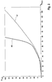
- Fig. 2 Exemplary relationships between the pressure P THZ in the master cylinder 12 and the associated actuating travel S pedal for the two operating modes Z A , Z P are shown schematically. Plotted is the pressure P THZ against the actuating travel S pedal , wherein characteristic curve 40 represents the first operating mode Z A and characteristic 41 the second operating mode Z P. Characteristic 40 or 41 represents the nominal relationship between the pressure P THZ and the actuating travel S Pedal in the respective operating mode Z A or Z P. According to the example, corresponding characteristic curves 40, 41 for the two operating modes 2 A , 2 P in the electronic Control unit 7 stored.
- the nominal pedal characteristic of the brake system in the first operating mode Z A ie the relationship between the pedal force and the pedal travel S pedal , is essentially determined by the simulator spring 21 (preferably a progressive compression spring, other spring elements are conceivable, eg an elastomer spring) of the pedal travel simulator 19.
- the displacement of the pedal travel simulator 19 depends linearly on the pedal travel S pedal .
- the pedal force and the pressure in the pedal travel simulator 19 are in a linear relationship.
- a characteristic curve 40 results which describes the pressure in the pedal travel simulator 19, which corresponds to the pressure P THZ measurable by means of the pressure sensor 15, as a function of the pedal travel S pedal .
- This nominal characteristic curve 40 which represents the normal brake function ("brake-by-wire" mode, first operating mode Z A ), is stored in the electronic control and regulation unit 7.
- the valves In the hydraulic fallback level (second operating mode Z P ), the valves, in particular the valves 14a, 14b, 20, 27a, 27b, are de-energized, and the driver is directly hydraulically connected to the wheel brakes 6 when the brake pedal 1 is actuated.
- the hydraulic design of the brake system and the vehicle-specific volume of the wheel brakes 6 thus results in a different pedal characteristic and the relationship between the measurable by pressure sensor 15 pressure P THZ and the pedal travel S pedal is described by curve 41.
- These nominal characteristic curve 41 which represents the second mode of operation Z P is stored in the electronic control and regulating unit. 7 How out Fig. 2 can be seen, the characteristics of the two operating modes Z P and Z A are significantly different.
- FIG. 3 is a schematic flow diagram illustrating an example method of operation.
- FIG a brake system shown.
- the brake system is in a passive or deactivated state 50 (assuming no brake pedal actuation by the driver).
- the brake system is usually started, for example, by the driver by switching on the engine ignition or in advance by opening the driver's door (optionally by means of appropriate environmental sensors eg Keyless entry).
- an initialization of the sensors of the brake system for example the pressure sensors 15, 30, 31 and the position sensors 17, 24, is carried out in block 51 so that they provide measured values after the initialization.
- the corresponding valves for example the separating valves 14a, 14b, the simulator release valve 20 and the connection valves 27a, 27b, and the brake booster function are activated, so that in the case of actuation of the brake pedal by the driver a "brake-by-wire" Braking can be performed.
- the brake system is then in an operational active state (first operating mode Z A , block 65) in which the brake valves 1 actuated the isolation valves 14a, 14b of the actuator 2 closed, the Simulatorabigabeventil 20 and the Zuschaltventile 27a, 27b of the pressure supply device 4 is opened are.
- the driver is then not directly hydraulically connected to the brake circuits I, II and wheel brakes 6, but actuates the pedal travel simulator 19, while the brake circuits I, II by the pressure supply means 4 with the pressure P soll (according to a predetermined brake booster function) are acted upon.
- the initialization path without driver operation (blocks 50, 51, 52, 65) is generally the rule, ie the valves 14a, 14b, 20, 27a, 27b are energized directly and the printing device 4 is activated.
- the brake system is in the second operating mode Z P (fallback mode). If now the engine ignition is switched on (or the brake system is supplied with electrical energy again), then the brake system is converted according to the exemplary method described below in the first operating mode Z A (block 65), an advantage of the method is that the transfer as comfortable as possible and without irritation of the driver is performed.
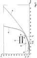
- the brake system is in the second operating mode Z P (fallback mode) and it is the characteristic 41 of the Fig. 4 effective.
- the Pedalweg S pedal and associated system pressure in the brake circuits I, II which corresponds to the pressure P THZ of the master cylinder 12 due to the open isolation valves 14a, 14b, according to the volume of the wheel brakes 6 and introduced via the driver pedal force to the point 80th (S 1 , P 1 ). If now the brake system, for example, by the driver by the engine ignition, started, then first in block 53 of the Fig.
- the position of the self-adjusting point 81 (S 2 , P 1 ) relative to the two nominal characteristic curves 40, 41 is determined in block 56 by a plausibility check or comparison using the current measured values of the sensors 15 and 17 (P THZ and S pedal ). as well as the characteristic curve 41 stored in block 54 for the second operating mode Z P and the characteristic curve 40 stored in block 55 for the second operating mode Z A. If it is detected in block 56 that the self-adjusting point 81 (S 2 , P 1 ) lies below the two nominal characteristic curves 40, 41, an active pedal correction, for example by means of the pressure supply device 4, is carried out (branch 57 to block 58).
- connection valves 27a, 27b are opened, so that the pressure supply device 4 is hydraulically connected to the brake circuits I, II, and thus also to the master cylinder 12.
- the pressure supply device 4 is further controlled such that pressure medium volume from the pressure supply device 4 via the open Zuschaltventile 27a, 27b and separating valves 14a, 14b is moved into the pressure chambers 10, 11 of the master cylinder 12, so that the brake pedal 1 against the acting pedal force the driver, ie constant pressure P 1 , is reset. Resetting the brake pedal 1 (the pad correction path) is in Fig. 4 represented by the arrow 83.
- Brake pedal 1 is set to the nominal point 82 of the characteristic curve 40 of the first operating mode Z A ("brake-by-wire" mode), so that the set pedal position to the resulting from the characteristic curve 40 pedal path S 3 for the (system) pressure P 1 corresponds.
- the pedal position is checked by means of the sensor 17.
- the brake system becomes fast, comfortable, and without irritating the driver during brake pedal operation transferred from the second operating mode in the first operating mode.
- the pedal correction corrects the brake system almost unnoticeably for the driver from the state of point 81 into the "brake-by-wire" operating state, which corresponds to point 82 on the driver's usual characteristic curve 40 of the first operating mode.
- the second case concerns the situation where the driver operates the brake pedal in the brake-by-wire mode, the brake system enters the fallback mode (eg due to a momentary power failure of the brake system), and then restarts or initializes the brake system while the driver stops on the brake pedal.
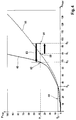
- Fig. 5 an exemplary diagram for the pedal travel S pedal and the associated pressure P THZ shown.
- the master cylinder 12 In the first operating mode, ie before switching to the hydraulic fallback level, the master cylinder 12 is connected to the pedal travel simulator 19 and it is the characteristic curve 40 of FIG Fig. 5 effective. According to the driver applied pedal force are thus the pressure P 2 on the master cylinder 12 and pedal travel 19 and the pedal travel S 4 before (point 84). In the brake circuits I, II there is a higher (system) pressure level due to the brake booster function of the pressure supply device 4.
- a plausibility check or a comparison based on the current measured values of the sensors 15 and 17 (P THZ and S pedal ) as well as the characteristic curves 41 and 40 stored in blocks 54 and 55, respectively, can be used to detect that the set value has changed Point 85 (S 5 , P 2 ) is above the nominal characteristic curves 40. If this is the case, then an active pedal correction, for example by means of the exhaust valves 29a-d, performed (branch 61 to block 62).
- the pedal correction in block 62 takes place, for example, by opening the exhaust valves 29a-d associated with the wheel brakes 6.
- the excess volume previously introduced via the wheel brakes 6 is discharged via the outlet valves 29a-d into the pressure medium reservoir 3 until the pedal travel of the brake pedal 1 again corresponds to the corresponding value S 4 of the nominal characteristic curve 40.
- the connection valves 27a, 27b are opened so that the pressure supply device 4 is connected to the brake circuits I, II.
- a pressure-displacement characteristic 42 of the pressure supply device 4 is stored in the control and regulation unit 7.
- An exemplary characteristic curve 42 for describing the relationship between piston position S piston and pressure P DBE of the pressure supply device 4 is shown in FIG Fig. 6 shown schematically.
- a check of the piston position S piston can be done by means of the sensor 24.
Description
Die Erfindung betrifft ein Verfahren gemäß Oberbegriff von Anspruch 1 und eine Bremsanlage gemäß Oberbegriff von Anspruch 14.The invention relates to a method according to the preamble of claim 1 and a brake system according to the preamble of claim 14.
In der Kraftfahrzeugtechnik finden "Brake-by-wire"-Bremsanlagen eine immer größere Verbreitung. Solche Bremsanlagen umfassen oftmals neben einem durch den Fahrzeugführer betätigbaren Hauptbremszylinder eine elektrisch steuerbare Druckbereitstellungseinrichtung, mittels welcher in der Betriebsart "Brake-by-wire" eine Betätigung der Radbremsen oder des Hauptbremszylinders stattfindet. Um dem Fahrzeugführer in der Betriebsart "Brake-by-wire" ein angenehmes Pedalgefühl zu vermitteln, umfassen die Bremsanlagen üblicherweise eine Bremspedalgefühl-Simulationseinrichtung. Bei diesen Bremsanlagen können die Radbremse auch ohne aktives Zutun des Fahrzeugführers aufgrund elektronischer Signale betätigt werden. Diese elektronischen Signale können beispielsweise von einem elektronischen Stabilitätsprogramm oder einem Abstandsregelsystem ausgegeben werden.In automotive engineering, brake-by-wire brake systems are becoming increasingly widespread. Such brake systems often include an actuatable by the vehicle master cylinder an electrically controllable pressure supply device by means of which in the operating mode "brake-by-wire" takes place an actuation of the wheel brakes or the master cylinder. To provide the driver with a comfortable pedal feel in the brake-by-wire mode, the brake systems typically include a brake pedal feel simulator. In these brake systems, the wheel brake can be operated without active intervention of the driver due to electronic signals. These electronic signals can be output, for example, from an electronic stability program or a distance control system.
Aus der internationalen Patentanmeldung
Es ist Aufgabe der vorliegenden Erfindung, ein Verfahren zum Betrieb einer Bremsanlage sowie eine Bremsanlage bereitzustellen, welches/welche dem Fahrzeugführer ein gleichbleibendes Bremspedalgefühl, insbesondere auch bei einem Übergang von einer Betriebsart in eine Betriebsart der Bremsanlage, bereitstellt. Insbesondere soll dem Fahrer der Falle eines Starts oder Neustarts der Bremsanlage das gewohnte Bremspedalgefühl sowie die Bremskraftverstärkte "Brake-by-wire"-Betreibsart möglichst schnell und komfortabel bereitgestellt werden.It is an object of the present invention to provide a method for operating a brake system and a brake system, which / which provides the driver with a consistent brake pedal feel, especially in a transition from a mode to an operating mode of the brake system. In particular, the driver of the case of a start or restart of the brake system, the usual brake pedal feeling and the brake-boosted "brake-by-wire" -Betreibsart be provided as quickly and conveniently.
Diese Aufgabe wird erfindungsgemäß durch ein Verfahren gemäß Anspruch 1 und eine Bremsanlage gemäß Anspruch 14 gelöst.This object is achieved by a method according to claim 1 and a brake system according to claim 14.
Der Erfindung liegt der Gedanke zugrunde, dass bei einem Übergang von dem zweiten Betriebsmodus in den ersten Betriebsmodus während einer Betätigung des Bremspedals ein elektronisch gesteuertes oder geregeltes Verstellen des Betätigungswegs des Bremspedals durchführt wird.The invention is based on the idea that during a transition from the second operating mode to the first operating mode during an actuation of the brake pedal, an electronically controlled or regulated adjustment of the actuating travel of the brake pedal is performed.
Bevorzugt wird bei dem Übergang von dem zweiten Betriebsmodus in den ersten Betriebsmodus während einer Betätigung des Bremspedals der Betätigungsweg des Bremspedals durch elektronisch gesteuertes oder geregeltes Ablassen von Druckmittel aus dem Hauptbremszylinder oder durch elektronisch gesteuertes oder geregeltes Zuführen von Druckmittel in den Hauptbremszylinder verstellt. Dies kann anhand der vorhandenen Komponenten der Bremsanlage, d.h. ohne zusätzliche Komponenten, durchgeführt werden.In the transition from the second operating mode to the first operating mode during an actuation of the brake pedal, the actuating travel of the brake pedal is preferably controlled by electronically controlled or regulated discharging Adjusted pressure medium from the master cylinder or by electronically controlled or regulated supply of pressure medium in the master cylinder. This can be done on the basis of the existing components of the brake system, ie without additional components.
Gemäß einer bevorzugten Ausführungsform des erfindungsgemäßen Verfahrens sind eine erste Kennlinie, welche einen Zusammenhang zwischen erster und zweiter Größe in dem ersten Betriebsmodus beschreibt, und eine zweite Kennlinie, welche einen Zusammenhang zwischen erster und zweiter Größe in dem zweiten Betriebsmodus beschreibt, vorgegebenen und eine Entscheidung, ob ein Ablassen oder ein Zuführen von Druckmittel durchgeführt wird, wird anhand eines Vergleichs von aktuellen Werte der ersten und zweiten Größe mit der ersten Kennlinie und/oder der zweiten Kennlinie getroffen. Der Betätigungsweg wird besonders bevorzugt auf einen Wert entsprechend der ersten Kennlinie verstellt.According to a preferred embodiment of the method according to the invention, a first characteristic, which describes a relationship between first and second variables in the first operating mode, and a second characteristic, which describes a relationship between first and second variables in the second operating mode, predetermined and a decision whether a discharge or supply of pressure medium is performed is based on a comparison of current values of the first and second size with the first characteristic and / or the second characteristic. The actuation path is particularly preferably adjusted to a value corresponding to the first characteristic curve.
Bevorzugt wird der Betätigungsweg durch Zuführen von Druckmittel verringert, wenn das Wertepaar aus erster und zweiter Größe nach einem Zuschalten des Pedalwegsimulators unterhalb der zweiten Kennlinie liegt, um das in den Pedalwegsimulator abgeflossene Druckmittelvolumen auszugleichen.Preferably, the actuation path is reduced by supplying pressure medium, if the pair of values of first and second size is after switching on the pedal travel simulator below the second characteristic curve to compensate for the pressure medium volume drained into the pedal travel simulator.
Bevorzugt wird der Betätigungsweg durch Ablassen von Druckmittel vergrößert, wenn das Wertepaar aus erster und zweiter Größe nach einem Zuschalten des Pedalwegsimulators oberhalb der ersten Kennlinie liegt, um das aus der/den Radbremse(n) stammende Druckmittelüberschussvolumen auszugleichen.Preferably, the actuation path is increased by releasing pressure medium, if the pair of values of first and second size is after switching on the pedal travel simulator above the first characteristic curve to compensate for the pressure surplus volume originating from the wheel brake (s).
Bei dem Übergang von dem zweiten in den ersten Betriebsmodus werden bevorzugt zunächst die Sensoren zur Messung der ersten und der zweiten Größe initialisiert und danach der Pedalwegsimulator mittels des Simulator-Freigabeventils angeschaltet. Änderungen der Werte der ersten und der zweiten Größe während des Zuschaltens des Pedalwegsimulators können so beobachtet und ausgewertet werden. Nach dem Zuschalten des Pedalwegsimulators ist der Fahrer sowohl mit dem Pedalwegsimulator als auch mit dem/den Bremskreis(en) hydraulisch verbunden, so dass sich ein Druckgleichgewicht herstellen kann. Besonders bevorzugt wird nach dem Zuschalten des Pedalwegsimulators das Verstellen des Betätigungswegs des Bremspedals durchgeführt.In the transition from the second to the first operating mode Preferably, first the sensors for measuring the first and the second size are initialized and then the pedal travel simulator is turned on by means of the simulator release valve. Changes in the values of the first and second quantities during the activation of the pedal travel simulator can thus be observed and evaluated. After switching on the pedal travel simulator, the driver is hydraulically connected both to the pedal travel simulator and to the brake circuit (s), so that a pressure equilibrium can be established. Particularly preferably, after the activation of the pedal travel simulator, the adjustment of the actuation travel of the brake pedal is carried out.
Bevorzugt wird das Verfahren in einer Bremsanlage mit zwei oder mehr Bremskreisen durchgeführt, bei welcher jeder Bremskreis über eine hydraulische Verbindungsleitung mit einem, vorteilhafterweise stromlos offenen, Trennventil mit dem Hauptbremszylinder und über eine weitere hydraulische Verbindungsleitung mit einem, vorteilhafterweise stromlos geschlossenen, Zuschaltventil mit der Druckbereitstellungseinrichtung verbunden ist.
Die Bremsanlage umfasst bevorzugt weiterhin eine Radbremsdruck-Modulationseinheit, die je Radbremse ein Einlassventil sowie ein Auslassventil zum Einstellen eines radindividuellen Bremsdrucks aufweist, der aus dem Druck in dem Bremskreis abgeleitet wird. Besonders bevorzugt leiten im nicht angesteuerten Zustand die Einlassventile die jeweiligen Bremskreisdrücke weiter. Ebenso sind die Auslassventile im nicht angesteuerten Zustand gesperrt.Preferably, the method is carried out in a brake system with two or more brake circuits, in which each brake circuit via a hydraulic connection line with a, advantageously normally open, isolation valve with the master cylinder and a further hydraulic connection line with a, preferably normally closed, Zuschaltventil with the pressure supply device connected is.
The brake system preferably further comprises a wheel brake pressure modulation unit, which has an inlet valve per wheel brake and an outlet valve for setting a wheel-specific brake pressure, which is derived from the pressure in the brake circuit. Particularly preferably, in the non-activated state, the intake valves forward the respective brake circuit pressures. Likewise, the exhaust valves are locked in the non-activated state.
Gemäß einer Weiterbildung des erfindungsgemäßen Verfahrens wird der Betätigungsweg des Bremspedals dadurch verringert, dass ein zwischen der Druckbereitstellungseinrichtung und dem Bremskreis angeordnetes Zuschaltventil geöffnet und die Druckbereitstellungseinrichtung derart angesteuert wird, dass Druckmittelvolumen in den Hauptbremszylinder verschoben wird. Es wird also die Druckbereitstellungseinrichtung mit dem Bremskreis und damit dem Hauptbremszylinder verbunden, so dass dann Druckmittel mittels der Druckbereitstellungseinrichtung über das geöffnete Zuschaltventil und die offene Verbindung zwischen Bremskreis und Hauptbremszylinder in den Hauptbremszylinder geführt werden kann, wodurch die Pedalposition korrigiert bzw. der Betätigungsweg des Bremspedals verstellt wird. Besonders bevorzugt wird der Betätigungsweg derart verstellt, wenn das Wertepaar aus erster und zweiter Größe nach dem Zuschalten des Pedalwegsimulators unterhalb der zweiten Kennlinie liegt.According to one embodiment of the method according to the invention, the actuation of the brake pedal is reduced by a between the pressure supply device and the brake circuit arranged Zuschaltventil open and the pressure supply device is controlled such that pressure fluid volume is moved into the master cylinder. It is thus the pressure supply device connected to the brake circuit and thus the master cylinder, so that pressure medium can be guided by the pressure supply device via the open Zuschaltventil and the open connection between the brake circuit and master cylinder in the master cylinder, whereby the pedal position corrects or the actuation of the brake pedal is adjusted. Particularly preferably, the actuation path is adjusted in such a way if the pair of values of the first and second quantities is below the second characteristic after the activation of the pedal travel simulator.
Gemäß einer Weiterbildung des erfindungsgemäßen Verfahrens wird der Betätigungsweg des Bremspedals dadurch vergrößert, dass ein zwischen einer Radbremse und einem Druckmittelvorratsbehälter angeordnetes Auslassventil geöffnet wird. Hierdurch kann das aus der/den Radbremse(n) stammende Druckmittelüberschussvolumen in den Druckmittelvorratsbehälter abfließen. Besonders bevorzugt wird der Betätigungsweg derart verstellt, wenn das Wertepaar aus erster und zweiter Größe nach dem Zuschalten des Pedalwegsimulators oberhalb der ersten Kennlinie liegt.According to one embodiment of the method according to the invention, the actuating travel of the brake pedal is increased by opening an outlet valve arranged between a wheel brake and a pressure medium reservoir. As a result, the pressure medium excess volume originating from the wheel brake (s) can flow off into the pressure medium reservoir. Particularly preferably, the actuation path is adjusted in such a way if the value pair of first and second variables lies after the activation of the pedal travel simulator above the first characteristic curve.
Bevorzugt wird die Druckbereitstellungseinrichtung durch eine Zylinder-Kolben-Anordnung gebildet, deren Kolben durch einen elektromechanischen Aktuator betätigbar ist.Preferably, the pressure-providing device is formed by a cylinder-piston arrangement whose piston can be actuated by an electromechanical actuator.
Gemäß einer bevorzugten Ausführungsform des erfindungsgemäßen Verfahrens wird zusätzlich, vorteilhafterweise gleichzeitig, zum Öffnen des Auslassventils ein zwischen der Druckbereitstellungseinrichtung und dem Bremskreis angeordnetes Zuschaltventil geöffnet. So kann ein Druckausgleich zwischen den Komponenten Druckbereitstellungseinrichtung, Bremskreis(en) und Hauptbremszylinder stattfinden. Besonders bevorzugt wird zusätzlich, vorteilhafterweise gleichzeitig, der Kolben der Druckbereitstellungseinrichtung auf eine vorbestimmte Kolbenposition eingestellt. Der Kolben befindet sich dann an der für den ersten Betriebsmodus richtigen Position. Die vorbestimmte Kolbenposition kann einfach gemäß einer vorgegebenen Kolbenposition-Druck-Kennlinie bestimmt werden, wobei die aktuell gemessene erste Größe berücksichtigt wird.According to a preferred embodiment of the method according to the invention is additionally, advantageously simultaneously, for opening the exhaust valve between the Pressure supply device and the brake circuit arranged Zuschaltventil opened. Thus, a pressure equalization between the components pressure supply device, brake circuit (s) and master cylinder take place. Particularly preferably, in addition, advantageously simultaneously, the piston of the pressure-providing device is set to a predetermined piston position. The piston is then at the correct position for the first operating mode. The predetermined piston position can be easily determined according to a predetermined piston position-pressure characteristic, taking into account the currently measured first variable.
Nach dem Verstellen des Betätigungswegs des Bremspedals wird bevorzugt ein zwischen dem Hauptbremszylinder und dem Bremskreis angeordnetes Trennventil geschlossen und danach durch die Druckbereitstellungseinrichtung ein vorbestimmter Solldruck eingestellt. Die Bremsanlage befindet sich dann in dem ersten Betriebsmodus, wobei der Fahrer das gewohnte Bremspedalgefühl erfährt. Besonders bevorzugt wird der Solldruck anhand der aktuellen Werte der ersten und zweiten Größe bestimmt.After adjusting the actuating travel of the brake pedal, a separating valve arranged between the master brake cylinder and the brake circuit is preferably closed and then set by the pressure supply device, a predetermined target pressure. The brake system is then in the first operating mode, wherein the driver experiences the usual brake pedal feel. Particularly preferably, the desired pressure is determined on the basis of the current values of the first and second variables.
Gemäß einer bevorzugten Weiterbildung des erfindungsgemäßen Verfahrens wird kein Verstellen des Betätigungswegs des Bremspedals durchgeführt, wenn der aktuelle Wert der zweiten Größe kleiner als ein vorgegebener erster Schwellenwert ist. In diesen Fällen ist die Betätigung des Bremspedals durch den Fahrer so gering, dass Abweichungen vom gewohnten Bremspedalgefühl nicht störend sind. Besonders bevorzugt wird zusätzlich zum aktuellen Wert der zweiten Größe der aktuelle Wert der ersten Größe herangezogen. Es wird dann kein Verstellen des Betätigungswegs des Bremspedals durchgeführt, wenn der aktuelle Wert der zweiten Größe kleiner als der vorgegebene erste Schwellenwert ist und der aktuelle Wert der ersten Größe kleiner als ein vorgegebener zweiter Schwellenwert ist.According to a preferred embodiment of the method according to the invention, no adjustment of the actuation path of the brake pedal is performed when the current value of the second variable is smaller than a predetermined first threshold value. In these cases, the operation of the brake pedal by the driver is so low that deviations from the usual brake pedal feel are not disturbing. Particularly preferably, in addition to the current value of the second variable, the current value of the first variable is used. It is then carried out no adjustment of the actuation path of the brake pedal, if the current value of the second size is less than the predetermined first threshold and the current value of the first size is less than a predetermined second threshold.
Bevorzugt handelt es sich um eine Bremsanlage für Kraftfahrzeuge, die in einer sog. "Brake-by-wire"-Betriebsart sowohl vom Fahrzeugführer als auch unabhängig vom Fahrzeugführer ansteuerbar ist, vorzugsweise in der "Brake-by-wire"-Betriebsart betrieben wird und in mindestens einer Rückfallbetriebsart betrieben werden kann, in der nur der Betrieb durch den Fahrzeugführer möglich ist.It is preferably a brake system for motor vehicles, which can be controlled in a so-called "brake-by-wire" mode both by the driver and independently of the driver, is preferably operated in the "brake-by-wire" mode and can be operated in at least one fallback mode in which only the operation by the driver is possible.
Die Erfindung betrifft auch eine Bremsanlage, in deren Steuer- und Regeleinheit bei einem Übergang von dem zweiten Betriebsmodus in den ersten Betriebsmodus während einer Betätigung des Bremspedals Verstellen des Betätigungswegs des Bremspedals durchgeführt wird. Weiter betrifft die Erfindung eine Bremsanlage, in deren elektronischen Steuer- und Regeleinheit ein erfindungsgemäßes Verfahren durchgeführt wird.The invention also relates to a brake system, is carried out in the control unit in a transition from the second operating mode in the first operating mode during actuation of the brake pedal adjusting the actuation path of the brake pedal. Furthermore, the invention relates to a brake system, in whose electronic control unit a method according to the invention is carried out.
Weitere bevorzugte Ausführungsformen der Erfindung ergeben sich aus den Unteransprüchen und der nachfolgenden Beschreibung anhand von Figuren.Further preferred embodiments of the invention will become apparent from the subclaims and the following description with reference to figures.
Es zeigen schematisch
- Fig. 1
- eine beispielgemäße Bremsanlage,
- Fig. 2
- beispielhafte Zusammenhänge zwischen dem Druck im Hauptbremszylinder und dem Betätigungsweg des Bremspedals für zwei verschiedene Betriebsmodi der beispielgemäßen Bremsanlage aus
Fig. 1 , - Fig. 3
- ein schematisches Ablaufdiagramm zur Veranschaulichung eines beispielgemäßen Verfahrens zum Betrieb der beispielgemäßen Bremsanlage aus
Fig. 1 , - Fig. 4
- Diagramm für den Pedalweg und den zugehörigen Druck zur Veranschaulichung eines ersten beispielgemäßen Verfahrens,
- Fig. 5
- Diagramm für den Pedalweg und den zugehörigen Druck zur Veranschaulichung eines zweiten beispielgemäßen Verfahrens,
- Fig. 6
- eine beispielsgemäße Kennlinie einer Druckbereitstellungseinrichtung.
- Fig. 1
- an exemplary brake system,
- Fig. 2
- exemplary relationships between the pressure in the master cylinder and the actuation of the brake pedal for two different modes of operation the exemplary brake system
Fig. 1 . - Fig. 3
- a schematic flow diagram for illustrating an example method for operating the exemplary brake system
Fig. 1 . - Fig. 4
- Diagram for the pedal travel and the associated pressure to illustrate a first exemplary method,
- Fig. 5
- Diagram for the pedal travel and the associated pressure to illustrate a second exemplary method,
- Fig. 6
- an exemplary characteristic of a pressure supply device.
In
Betätigungseinrichtung 2 umfasst einen zweikreisigen Hauptbremszylinder bzw. Tandemhauptzylinder 12 mit zwei in einem (Hauptbremszylinder-)Gehäuse hintereinander angeordneten hydraulischen Kolben 8, 9, welche hydraulische Druckkammern 10, 11 begrenzen. Die Druckkammern 10, 11 stehen über in den Kolben 8, 9 ausgebildete radiale Bohrungen mit dem Druckmittelvorratsbehälter 3 in Verbindung, wobei diese Bohrungen durch eine Relativbewegung der Kolben 8, 9 im Gehäuse absperrbar sind. Außerdem ist jede Druckkammer 10, 11 mittels einer hydraulischen Leitung 13a, 13b mit einem Bremskreis I, II mit je zwei Radbremskreisen mit hydraulisch betätigbaren Radbremsen 6 verbunden. In den hydraulischen Leitungen 13a, 13b ist je ein Trennventil 14a, 14b eingefügt, das als ein elektrisch betätigbares, vorzugsweise stromlos offenes, 2/2-Wegeventil ausgebildet ist. Ein an den Druckraum 11 angeschlossener, vorzugsweise redundant ausgeführter, Drucksensor 15 erfasst den im Druckraum 11 durch ein Verschieben des zweiten Kolbens 9 aufgebauten Druck PTHZ, welcher der vom Fahrer erzeugten Pedalkraft entspricht. Außerdem nehmen die Druckkammern 10, 11 nicht näher bezeichnete Rückstellfedern auf, die die Kolben 8, 9 entgegen der Betätigungsrichtung vorspannen. Eine am Bremspedal 1 angekoppelte Kolbenstange 16 wirkt mit dem ersten (Hauptzylinder-)Kolben 8 zusammen, wobei eine den Betätigungsweg des Bremspedals 1 charakterisierende Größe SPedal, z.B. der Betätigungsweg oder -winkel des Bremspedals 1 selbst oder der Betätigungsweg des mit dem Bremspedal gekoppelten Kolbens 8, von einem, vorzugsweise redundant ausgeführten, Wegsensor 17 erfasst wird.Actuator 2 comprises a dual-circuit master cylinder or
Betätigungseinrichtung 2 umfasst weiter einen Pedalwegsimulator (auch Pedalgefühlsimulatoreinrichtung genannt) 19, welcher mit dem Hauptbremszylinder 12 zusammenwirkt und dem Fahrzeugführer in einem ersten Betriebsmodus (einer sogenannten "Brake-by-wire"-Betriebsart) ein angenehmes Pedalgefühl vermittelt. Pedalwegsimulator 19 ist hydraulisch betätigbar und mit zumindest einer Druckkammer 10, 11 des Hauptbremszylinders 12 verbunden. Pedalwegsimulator 19 ist mittels eines elektrisch betätigbaren Simulatorfreigabeventils 20 zu- und abschaltbar.Actuator 2 further comprises a pedal travel simulator (also called pedal feel simulator means) 19 which cooperates with
Pedalwegsimulator 19 besteht beispielsgemäß im Wesentlichen aus zwei Simulatorkammern, einer Simulatorfederkammer mit Simulatorfeder 21 sowie einem diese Kammern voneinander trennenden Simulatorkolben (Stufenkolben). Dabei sind die Simulatorkammern an jeweils eine Druckkammer 10, 11 des Hauptbremszylinders 12 angeschlossen, während die Simulatorfederkammer unter Zwischenschaltung des Simulatorfreigabeventils 20 mit dem Druckmittelvorratsbehälter 3 verbindbar ist. Ein dem Simulatorfreigabeventil 20 parallel geschaltetes Rückschlagventil ist an die Simulatorfederkammer angeschlossen und ermöglicht unabhängig vom Schaltzustand des Simulatorfreigabeventils 20 und unabhängig von einer Drosselwirkung der hydraulischen Simulator-Abströmverbindungen ein weitgehend ungedrosseltes Einströmen des Druckmittels in die Simulatorfederkammer. Das Simulatorfreigabeventil 20 ist als ein elektrisch betätigbares, vorzugsweise stromlos geschlossenes, 2/2-Wegeventil ausgebildet.For example,
Die elektrohydraulische Druckbereitstellungseinrichtung 4 ist als eine hydraulische Zylinder-Kolben-Anordnung ausgebildet, deren Kolben 22 von einem schematisch angedeuteten Elektromotor 23 unter Zwischenschaltung eines nicht dargestellten Rotations-Translationsgetriebes betätigbar ist. Der Elektromotor 23 sowie das Rotations-Translations-Getriebe bilden einen Linearaktuator, wobei zur Erfassung einer für die Position/Lage des Kolbens 22 der Druckbereitstellungseinrichtung 4 charakteristischen Größe ein Sensor 24 vorhanden ist, welcher beispielsgemäß als ein der Erfassung der Rotorlage des Elektromotors 23 dienender Rotorlagensensor 24 ausgeführt ist. Weitere Sensoren, wie beispielsweise ein Temperatursensor, liefern der elektronischen Steuer- und Regeleinheit 7 Zustandsinformationen zum Elektromotor 23 bzw. zum Linearaktuator. Kolben 22 begrenzt einen Druckraum 25, welcher über hydraulische Leitungen 26a, 26b mit je einem elektrisch betätigbaren Zuschaltventil 27a, 27b mit den Bremskreisen I, II verbindbar ist. Dabei ist den Zuschaltventilen 27a, 27b je ein zu dem Druckraum 25 hin schließendes Rückschlagventil parallel geschaltet. Außerdem steht Druckraum 25 über ein zum Druckmittelvorratsbehälter 3 schließendes Rückschlagventil 34 mit diesem in Verbindung. Die Zuschaltventile 27a, 27b sind als elektrisch betätigbare, vorzugsweise stromlos geschlossene, 2/2-Wegeventile ausgebildet. In Druckraum 25 ist eine Feder 33 angeordnet, welche den Kolben 22 entgegen der Druckaufbaurichtung belastet.The electrohydraulic
Zur Modulation des Druckes an den Radbremsen 6 umfasst die hydraulische Druckmodulationseinrichtung 5 beispielsgemäß je Radbremse 6 ein Einlassventil 28a-28d und ein Auslassventil 29a-29d. Die Eingangsanschlüsse der Einlassventile 28a-28d bzw. die Bremskreise I, II können mit dem Druck des Hauptbremszylinders 12 (über die Leitungen 13a, 13b mit den Trennventilen 14a, 14b) oder dem Druck der Druckbereitstellungseinrichtung 4 (über die Leitungen 26a, 26b mit den Zuschaltventilen 27a, 27b) versorgt werden. Die Ausgangsanschlüsse der Auslassventile 29a-29d sind über Rücklaufleitungen 32a, 32b mit dem drucklosen Druckmittelvorratsbehälter 3 verbunden (sogenanntes offenes System). Ergänzend ist noch zu erwähnen, dass sämtliche kreisförmigen Symbole zum Druckmittelvorratsbehälter 3 führende hydraulische Leitungen darstellen. Vorteilhafterweise sind die Einlassventile 28a-28d als elektrisch betätigbare, stromlos offene Druckregelventile und die Auslassventile 29a-29d als elektrisch betätigbare, stromlos geschlossene 2/2-Wegeventile ausgebildet.To modulate the pressure at the
Beispielsgemäß ist in jedem Bremskreis I, II ein Drucksensor 30, 31 zum Erfassen des an den Eingangsanschlüsse der zugehörigen Einlassventile 28a, 28b; 28c, 28d herrschenden Drucks angeordnet. Alternativ ist es denkbar, dass in nur einem der beiden Bremskreise I, II ein Drucksensor angeordnet ist oder dass ein Drucksensor in der Leitung 26a, 26b zwischen Druckraum 25 und Zuschaltventilen 27a, 27b angeordnet ist. Mittels dieses Drucksensors oder dieser Drucksensoren ist es möglich, den Druck Pist der Druckbereitstellungseinrichtung 4 (bei geschlossenen Trennventilen 14a, 14b) zu bestimmen.By way of example, in each brake circuit I, II, a
In einem ersten Betriebsmodus ZA (einer sogenannten "Brake-by-wire"-Betriebsart mit Bremskraftverstärkung) werden die Bremskreise I, II mit dem Druck der Druckbereitstellungseinrichtung 4 beaufschlagt. Hierzu sind beispielsgemäß die Zuschaltventile 27a, 27b geöffnet, so dass die Druckbereitstellungseinrichtung 4 mit den Bremskreisen I, II hydraulisch verbunden ist. Hauptbremszylinder 12 ist mittels der geschlossenen Trennventile 14a, 14b von den Bremskreisen I, II bzw. Radbremsen 6 getrennt. Simulatorfreigabeventil 20 ist geöffnet, so dass Pedalwegsimulator 19 zu- bzw. angeschaltet ist. Im Falle einer Betätigung SPedal des Bremspedals 1 wird Druckmittelvolumen aus den Druckkammern 10, 11 des Hauptbremszylinders 12 in die Simulatorkammern des Pedalwegsimulators 19 verschoben. Druckbereitstellungseinrichtung 4 wird mittels der elektronischen Steuer- und Regeleinheit 7 angesteuert, um einen Solldruck PSoll zur Beaufschlagung der Bremskreise I, II zu bereitzustellen. Der Wert für den Solldruck PSoll der Druckbereitstellungeinrichtung 4 wird, z.B. in der elektronischen Steuer- und Regeleinheit 7, anhand einer vorgegebenen Bremskraftverstärkungsfunktion und des, z.B. mittels der Sensoren 15 und 17, bestimmten Fahrerbremswunsches (SPedal, PTHZ) berechnet.In a first operating mode Z A (a so-called "brake-by-wire" mode with brake booster), the brake circuits I, II are acted upon by the pressure of the pressure-providing
Beispielsgemäß wird der Solldruck PSoll gemäß der folgenden Formel aus den gemessenen Größen PTHZ und SPedal bestimmt: ![]()
- fS: Bremsdruck-Verstärkungsfunktion in Abhängigkeit von dem Pedalweg SPedal,
- fP: Bremsdruck-Verstärkungsfunktion in Abhängigkeit vom Druck PTHZ,
- λS: Gewichtungsfaktor bzw. Gewichtungsfunktion für Druckanteil fS, und
- λP: Gewichtungsfaktor bzw. Gewichtungsfunktion für Druckanteil fP.
- f S : brake pressure boosting function as a function of the pedal travel S pedal ,
- f P : brake pressure boost function as a function of pressure P THZ ,
- λ S : weighting factor or weighting function for pressure component f S , and
- λ P : Weighting factor or weighting function for pressure component f P.
Der Solldruck PSoll wird also durch eine gewichtete Überlagerung eines auf der Pedal-/Kolbenweggröße SPedal basierenden Druckanteils fS sowie eines auf der Druckgröße PTHZ basierten Druckanteils fP ermittelt. Die Gewichtungsfaktoren können jeweils z.B. Werte zwischen Null und Eins annehmen. Durch entsprechende Vorgabe bzw. Definition und Parameterwahl bezüglich der vorgegebenen Bremsdruck-Verstärkungsfunktionen fS, fP und der vorgegebenen Gewichtungsfaktoren λS, λP ist eine spezifische Anpassung der Solldruck-Berechnung an die vorliegende Bremsanlage und die Wünsche bezüglich der Auslegung der Bremsanlage möglich.The setpoint pressure P setpoint is thus determined by a weighted superimposition of a pressure component f S based on the pedal / piston stroke size S pedal and a pressure component f P based on the pressure variable P THZ . The weighting factors can each assume, for example, values between zero and one. By appropriate specification or definition and parameter selection with respect to the predetermined brake pressure boosting functions f S , f P and the predetermined weighting factors λ S , λ P is a specific adaptation of the desired pressure calculation of the present brake system and the wishes regarding the design of the brake system possible.
In einem zweiten Betriebsmodus ZP (einer sogenannten Rückfallbetriebsart) werden die Bremskreise I, II mit dem Druck des Hauptbremszylinders 12 beaufschlagt. Hierzu sind die Trennventile 14a, 14b geöffnet, so dass der Hauptbremszylinder 12 mit den Bremskreisen I, II hydraulisch verbunden ist. Druckbereitstellungseinrichtung 4 ist mittels der geschlossenen Zuschaltventile 27a, 27b von den Bremskreisen I, II bzw. Radbremsen 6 getrennt. Simulatorfreigabeventil 20 ist geschlossen, so dass Pedalwegsimulator 19 abgeschaltet ist. Im Falle einer Betätigung SPedal des Bremspedals 1 wird Druckmittelvolumen aus den Druckkammern 10, 11 des Hauptbremszylinders 12 in die Bremskreise I, II bzw. Radbremsen 6 verschoben.In a second operating mode Z P (a so-called fallback mode), the brake circuits I, II are acted upon by the pressure of the
In
Die nominelle Pedalkennlinie der Bremsanlage im ersten Betriebsmodus ZA, d.h. der Zusammenhang zwischen der Pedalkraft und dem Pedalweg SPedal, wird im Wesentlichen durch die Simulatorfeder 21 (vorzugsweise eine progressive Druckfeder, andere Federelemente sind denkbar, z.B. eine Elastomerfeder) des Pedalwegsimulators 19 bestimmt. Das Schluckvolumen des Pedalwegsimulators 19 hängt linear von dem Pedalweg SPedal ab. Ebenso stehen die Pedalkraft und der Druck im Pedalwegsimulator 19 in einem linearen Zusammenhang. Entsprechend ergibt sich eine Kennlinie 40, welche den Druck im Pedalwegsimulator 19, welcher dem mittels Drucksensor 15 messbaren Druck PTHZ entspricht, in Abhängigkeit von dem Pedalweg SPedal beschreibt. Diese nominelle Kennlinie 40, welche die Normalbremsfunktion ("Brake-by-wire"-Betriebsart, erster Betriebsmodus ZA) darstellt, ist in der elektronischen Steuer- und Regeleinheit 7 abgelegt.The nominal pedal characteristic of the brake system in the first operating mode Z A , ie the relationship between the pedal force and the pedal travel S pedal , is essentially determined by the simulator spring 21 (preferably a progressive compression spring, other spring elements are conceivable, eg an elastomer spring) of the
In der hydraulischen Rückfallebene (zweiter Betriebsmodus ZP) sind die Ventile, insbesondere die Ventile 14a, 14b, 20, 27a, 27b, stromlos, und der Fahrer bei einer Betätigung des Bremspedals 1 direkt hydraulisch mit den Radbremsen 6 verbunden. Entsprechend der hydraulischen Auslegung der Bremsanlage und der fahrzeugspezifischen Volumenaufnahme der Radbremsen 6 ergibt sich somit eine andere Pedalkennlinie und der Zusammenhang zwischen dem mittels Drucksensor 15 messbaren Druck PTHZ und dem Pedalweg SPedal wird durch Kennlinie 41 beschrieben. Auch diese nominelle Kennlinie 41, welche den zweiten Betriebsmodus ZP darstellt, ist in der elektronischen Steuer- und Regeleinheit 7 abgelegt. Wie aus
In
Ist das Fahrzeug zunächst abgestellt oder wird die Bremsanlage nicht mit elektrischer Energie versorgt, so befindet die Bremsanlage in einem Passiv- oder abgeschalteten Zustand 50 (keine Bremspedalbetätigung durch den Fahrer vorausgesetzt). Die Bremsanlage wird üblicherweise z.B. vom Fahrer durch das Einschalten der Motorzündung oder im Vorfeld durch das Öffnen der Fahrertür (optional mittels entsprechender Umfeldsensorik z.B. Keyless-Entry) gestartet. Es wird zunächst in Block 51 eine Initialisierung der Sensoren der Bremsanlage, beispielsgemäß der Drucksensoren 15, 30, 31 und der Lagesensoren 17, 24, durchgeführt, so dass diese nach der Initialisierung Messwerte bereitstellen. In Block 52 werden die entsprechenden Ventile, beispielsgemäß die Trennventile 14a, 14b, das Simulatorfreigabeventil 20 und die Zuschaltventile 27a, 27b, sowie die Bremskraftverstärkungsfunktion aktiviert, so dass im Falle einer Betätigung des Bremspedals durch den Fahrer eine "Brake-by-wire"-Bremsung durchgeführt werden kann. Die Bremsanlage befindet sich dann in einen betriebsbereiten Aktiv-Zustand (erster Betriebsmodus ZA, Block 65), in welchem bei betätigtem Bremspedal 1 die Trennventile 14a, 14b der Betätigungseinrichtung 2 geschlossen, das Simulatorfreigabeventil 20 und die Zuschaltventile 27a, 27b der Druckbereitstellungseinrichtung 4 geöffnet sind. Der Fahrer ist dann nicht direkt hydraulisch mit den Bremskreisen I, II bzw. Radbremsen 6 verbunden, sondern betätigt den Pedalwegsimulator 19, während die Bremskreise I, II durch die Druckbereitstellungseinrichtung 4 mit dem Druck Psoll (gemäß einer vorgegebenen Bremskraftverstärkungsfunktion) beaufschlagt werden. Der Initialisierungspfad ohne Fahrerbetätigung (Blöcke 50, 51, 52, 65) ist generell der Regelfall, d.h. die Ventile 14a, 14b, 20, 27a, 27b werden direkt bestromt und die Durckbereitstellungseinrichtung 4 ist aktiviert.If the vehicle is initially parked or if the brake system is not supplied with electrical energy, the brake system is in a passive or deactivated state 50 (assuming no brake pedal actuation by the driver). The brake system is usually started, for example, by the driver by switching on the engine ignition or in advance by opening the driver's door (optionally by means of appropriate environmental sensors eg Keyless entry). Initially, an initialization of the sensors of the brake system, for example the
Ist das Fahrzeug abgestellt (oder wird die Bremsanlage nicht mit elektrischer Energie versorgt) und betätigt der Fahrer das Bremspedal 1, so befindet sich die Bremsanlage in dem zweiten Betriebsmodus ZP (Rückfallbetriebsart). Wird nun die Motorzündung eingeschaltet (oder wird die Bremsanlage wieder mit elektrischer Energie versorgt), so wird die Bremsanlage entsprechend dem im Folgenden beschriebenen beispielsgemäßen Verfahren in den ersten Betriebsmodus ZA (Block 65) überführt, wobei ein Vorteil des Verfahrens ist, dass die Überführung möglichst komfortabel und ohne Irritation des Fahrers durchgeführt wird.If the vehicle is parked (or the brake system is not supplied with electrical energy) and the driver operates the brake pedal 1, then the brake system is in the second operating mode Z P (fallback mode). If now the engine ignition is switched on (or the brake system is supplied with electrical energy again), then the brake system is converted according to the exemplary method described below in the first operating mode Z A (block 65), an advantage of the method is that the transfer as comfortable as possible and without irritation of the driver is performed.
Im Weiteren wird beispielsgemäß zwischen den folgenden zwei Fällen unterschieden:
- Der erste Fall betrifft die Situation, dass der Fahrer das Bremspedal während eines Passiv- oder abgeschalteten Zustands betätigt und dann die Bremsanlage gestartet bzw. initialisiert wird, während der Fahrer das Bremspedal weiter betätigt. Dies entspricht z.B. dem Fall, dass der Fahrer im abgestellten Fahrzeug sitzt, das Bremspedal betätigt und dann die Zündung einschaltet. Zur Veranschaulichung des ersten Falles ist in
Fig. 4 ein beispielhaftes Diagramm für den Pedalweg SPedal und den zugehörigen Druck PTHZ dargestellt.
- The first case concerns the situation where the driver depresses the brake pedal during a passive or off state and then starts or initializes the brake system while the driver continues to operate the brake pedal. This corresponds for example to the case that the driver sits in the parked vehicle, actuates the brake pedal and then turns on the ignition. To illustrate the first case is in
Fig. 4 an exemplary diagram for the pedal travel S pedal and the associated pressure P THZ shown.
Betätigt also der Fahrer das Bremspedal während eines Passiv- oder abgeschalteten Zustands (d.h. ohne vorherige Initialisierung der Bremsanlage), so befindet sich die Bremsanlage in dem zweiten Betriebsmodus ZP (Rückfallbetriebsart) und es ist die Kennlinie 41 der
Die Lage des sich einstellenden Punkts 81 (S2, P1) relativ zu den beiden nominellen Kennlinien 40, 41 wird in Block 56 durch eine Plausibilisierung bzw. einen Vergleich anhand der aktuellen Messwerte der Sensoren 15 und 17 (PTHZ und SPedal) sowie der in Block 54 abgelegten Kennlinie 41 für den zweiten Betriebsmodus ZP und der in Block 55 abgelegten Kennlinien 40 für den zweiten Betriebsmodus ZA überprüft. Wird in Block 56 erkannt, dass der sich einstellende Punkt 81 (S2, P1) unterhalb der beiden nominellen Kennlinien 40, 41 liegt, so wird eine aktive Pedalkorrektur, z.B. mittels der Druckbereitstellungseinrichtung 4, durchgeführt (Zweig 57 zu Block 58).The position of the self-adjusting point 81 (S 2 , P 1 ) relative to the two nominal
Hierzu werden in Block 58 zunächst vorzugsweise die Zuschaltventile 27a, 27b geöffnet, so dass die Druckbereitstellungseinrichtung 4 mit den Bremskreisen I, II, und damit auch mit dem Hauptbremszylinder 12, hydraulisch verbunden ist. In Block 58 wird weiter die Druckbereitstellungseinrichtung 4 derart angesteuert, dass Druckmittelvolumen aus der Druckbereitstellungseinrichtung 4 über die geöffneten Zuschaltventile 27a, 27b und Trennventile 14a, 14b in die Druckkammern 10, 11 des Hauptbremszylinder 12 verschoben wird, so dass das Bremspedal 1 gegen die einwirkende Pedalkraft des Fahrers, d.h. konstanten Druck P1, zurückgestellt wird. Das Zurückstellen des Bremspedals 1 (der Padalkorrekturweg) wird in
Nach Beendigung der Pedalkorrektur (Block 58) wird in Block 59 der Hauptbremszylinder 12 durch Schließen der Trennventile 14a, 14b von den Bremskreisen I, II getrennt. In Block 60 wird dann die Bremskraftverstärkung langsam angehoben, bis sich die Bremsanlage dann in Block 65 in dem ersten Betriebsmodus ZA ("Brake-by-wire"-Betriebsart mit Bremskraftverstärkung) befindet.After completion of the pedal correction (block 58) is in
Durch die oben beschriebene Vorgehensweise mit Bremspedalkorrektur wird die Bremsanlage schnell, komfortabel und ohne Irritation des Fahrers während einer Bremspedalbetätigung aus dem zweiten Betriebsmodus in den ersten Betriebsmodus überführt. Insbesondere wird durch die Pedalkorrektur die Bremsanlage fast unmerklich für den Fahrer aus dem Zustand des Punkts 81 in den "Brake-by-wire"-Betriebszustand überführt, welcher dem Punkt 82 auf der für den Fahrer gewohnten Kennlinie 40 des ersten Betriebsmodus entspricht.With the brake pedal correction approach described above, the brake system becomes fast, comfortable, and without irritating the driver during brake pedal operation transferred from the second operating mode in the first operating mode. In particular, the pedal correction corrects the brake system almost unnoticeably for the driver from the state of
Der zweite Fall betrifft die Situation, dass der Fahrer das Bremspedal in der "Brake-by-wire"-Betriebsart betätigt, die Bremsanlage in die Rückfallbetriebsart übergeht (z.B. wegen eines kurzzeitigen Stromausfalls der Bremsanlage) und dann ein Neustart bzw. eine Initialisierung der Bremsanlage durchgeführt wird, während der Fahrer auf dem Bremspedal stehen bleibt. Zur Veranschaulichung des zweiten Falles ist in
Erfolgt ein Neustart der Bremsanlage während einer durch eine Bremspedalbetätigung initiierten "Brake-by-wire"-Bremsung mit Bremskraftverstärkung (z.B. hervorgerufen durch einen kurzzeitigen Stromausfall), so sind alle Ventile, insbesondere die Ventile 14a, 14b, 20, 27a, 27b, sowie die Druckbereitstellungseinrichtung 4 der Bremsanlage für eine begrenzte Zeit ohne elektrische Energieversorgung, d.h. stromlos. Die Bremsanlage fällt also aus dem ersten Betriebsmodus mit Fahrerbetätigung in die hydraulische Rückfallebene zurück, d.h. in den zweiten Betriebsmodus ZP bei Fahrerbetätigung.If the brake system is restarted during a "brake-by-wire" braking with brake booster initiated by a brake pedal actuation (eg caused by a momentary power failure), then all the valves, in particular the
In dem ersten Betriebsmodus, d.h. vor dem Umschalten in die hydraulische Rückfallebene, ist der Hauptbremszylinder 12 mit dem Pedalwegsimulator 19 verbunden und es ist die Kennlinie 40 der
Ist dann die elektrische Energieversorgung wieder vorhanden, so wird zunächst in Block 53 der
In Block 56 kann nun durch eine Plausibilisierung bzw. einen Vergleich anhand der aktuellen Messwerte der Sensoren 15 und 17 (PTHZ und SPedal) sowie der in den Blöcken 54 bzw. 55 abgelegten Kennlinien 41 bzw. 40 erkannt werden, dass der sich eingestellte Punkt 85 (S5, P2) oberhalb der nominellen Kennlinien 40 liegt. Ist dies der Fall, so wird eine aktive Pedalkorrektur, z.B. mittels der Auslassventile 29a-d, durchgeführt (Zweig 61 zu Block 62).In
Die Pedalkorrektur in Block 62 erfolgt beispielsgemäß durch das Öffnen der den Radbremsen 6 zugeordneten Auslassventile 29a-d. Das über die Radbremsen 6 zuvor eingespeiste Überschussvolumen wird über die Auslassventile 29a-d solange in den Druckmittelvorratsbehälter 3 abgelassen, bis der Pedalweg des Bremspedals 1 wieder dem entsprechenden Wert S4 der nominellen Kennlinie 40 entspricht. Auch werden in Block 62 die Zuschaltventile 27a, 27b geöffnet, damit die Druckbereitstellungseinrichtung 4 mit den Bremskreisen I, II verbunden ist.The pedal correction in
Zeitgleich wird der Kolben 22 der Druckbereitstellungseinrichtung 4 auf eine Kolbenposition SKolben eingestellt, welche einem Druck der Druckbereitstellungseinrichtung 4 gleich dem Druck PTHZ im Hauptbremszylinder 12 (PTHZ=P2) entspricht. Hierzu ist eine Druck-Weg-Kennlinie 42 der Druckbereitstellungseinrichtung 4 in der Steuer- und Regeleinheit 7 abgelegt. Eine beispielhafte Kennlinie 42 zur Beschreibung des Zusammenhangs zwischen Kolbenposition SKolben und Druck PDBE der Druckbereitstellungseinrichtung 4 ist in
Sind Pedalkorrektur und Einstellung des Kolbens 22 abgeschlossen, so werden in Block 59 die Trennventile 14a, 14b geschlossen und dann in Block 60 die Bremskraftverstärkung langsam entsprechend des Fahrerwunsches angehoben, bis sich die Bremsanlage wieder in dem ersten Betriebsmodus ZA ("Brake-by-wire"-Betriebsart mit Bremskraftverstärkung) befindet.Are pedal correction and adjustment of the
Ergänzend zu den beiden oben beschriebenen Fällen (erster und zweiter Fall) wird in Fällen, in denen die Betätigung des Bremspedals 1 durch den Fahrer gering ist, keine Pedalkorrektur durchgeführt. Hierzu wird in Block 56 überprüft, ob sich der aktuelle Pedalweg SPedal bzw. der aktuelle Betriebspunkt (SPedal, PTHZ) der Bremsanlage unterhalb eines vorgegebenen Schwellenwertes Sg bzw. innerhalb eines vorgegebenen Kennfeldbereichs 44, welches z.B. durch zwei Schwellenwerte Sg und Pg definiert ist, befindet (siehe
Claims (15)
- Method for operating a brake system for motor vehicles, comprising:• a master brake cylinder (12) which can be actuated by means of a brake pedal (1) and which is separably (14a, 14b) connected to at least one brake circuit (I, II) with at least one hydraulically actuable wheel brake (6), wherein a first variable (PTHZ) which characterizes a pressure in the master brake cylinder (12) and a second variable (SPedal) which characterizes an actuation travel of the brake pedal (1) are measured at least from time to time,• a hydraulically actuable pedal travel simulator (19) which is or can be connected to the master brake cylinder (12) and which is designed so as to be capable of being switched on and off by means of a simulator release valve (20),• an electrically controllable pressure supply device (4) which is separably (27a, 27b) connected to the brake circuit (I, II) and which is formed, in particular, by a cylinder-piston arrangement whose piston (22) can be actuated by an electromechanical actuator (23), and• an electronic open-loop and closed-loop control unit (7) for activating the electrically controllable pressure supply device (4) and valves (20, 14a, 14b, 27a, 27b, 28a-d, 29a-d) of the brake system,wherein, when the brake pedal (1) is actuated, in a first operating mode (ZA) the brake circuit (I, II) is provided with a pressure (PSetp) of the pressure supply device (4), and in a second operating mode (ZP) it is provided with the pressure (PTHZ) of the master brake cylinder (12),
characterized in that
in the case of a changeover from the second operating mode (ZP) into the first operating mode (ZA) during actuation of the brake pedal (1) the actuation travel (SPedal) of the brake pedal (1) is adjusted under electronic open-loop or closed-loop control. - Method according to Claim 1, characterized in that in the case of the changeover from the second operating mode (ZP) into the first operating mode (ZA) during actuation of the brake pedal (1) the actuation travel (SPedal) of the brake pedal (1) is adjusted by discharging pressure medium, under electronic open-loop or closed-loop control, from the master brake cylinder (62) or by feeding pressure medium into the master brake cylinder (58) under electronic open-loop or closed-loop control.
- Method according to Claim 1 or 2, characterized in that a first characteristic curve (40), which describes a relationship between a first and second variable (PTHZ, SPedal) in the first operating mode (ZA), and a second characteristic curve (41) which describes a relationship between the first and second variables (PTHZ, SPedal) in the second operating mode (ZP), are predefined, and in that by comparing the current values of the first and second variables (PTHZ, SPedal) with the first characteristic curve (40) and/or the second characteristic curve (41) it is decided whether pressure medium will be discharged or fed in.
- Method according to Claim 3, characterized in that the actuation travel (SPedal) is reduced by feeding in pressure medium if the value pair composed of the first and second variables (S2, P1) is below the second characteristic curve (41) after the pedal travel simulator (19) is activated.
- Method according to Claim 3 or 4, characterized in that the actuation travel (SPedal) is increased by discharging pressure medium if the value pair composed of the first and second variables (S5, P2) is above the first characteristic curve (40) after the pedal travel simulator is activated.
- Method according to one of Claims 3 to 5, characterized in that the actuation travel (SPedal) is adjusted to a value (S3, S4) in accordance with the first characteristic curve (40).
- Method according to one of the preceding claims, characterized in that in the case of the changeover from the second operating mode (ZP) into the first operating mode (ZA), the sensors (15, 17) for measuring the first and second variables (PTHZ, SPedal) are firstly initialized and then the pedal travel simulator is switched on (53) by means of the simulator release valve (20), and in that in particular afterwards the adjustment of the actuation travel (SPedal) of the brake pedal (1) is carried out.
- Method according to one of the preceding claims, characterized in that the actuation travel (SPedal) of the brake pedal (1) is reduced (58) in that an activation valve (27a, 27b) which is arranged between the pressure supply device (4) and the brake circuit (I, II) is opened, and the pressure supply device (4) is activated in such a way that pressure medium volume is forced into the master brake cylinder (12).
- Method according to one of the preceding claims, characterized in that the actuation travel (SPedal) of the brake pedal (1) is increased (62) in that an outlet valve (29a, 29b) which is arranged between a wheel brake (6) and a pressure medium reservoir container (3) is opened.
- Method according to Claim 9, characterized in that in addition, in particular simultaneously, an activation valve (27a, 27b) which is arranged between the pressure supply device (4) and the brake circuit (I, II) is opened.
- Method according to Claim 10, characterized in that the pressure supply device (4) is formed by a cylinder-piston arrangement whose piston (22) can be actuated by an electromechanical actuator (23), and in that in addition, in particular simultaneously, the piston (22) of the pressure supply device (4) is set to a piston position (SK1) which is predetermined, in particular, according to a predefined piston position pressure characteristic curve (42).
- Method according to one of the preceding claims, characterized in that after the adjustment of the actuation travel (SPedal) of the brake pedal (1) an isolating valve (14a, 14b) which is arranged between the master brake cylinder (12) and the brake circuit (I, II) is closed (59), and then a predetermined setpoint pressure (PSetp) is set (60) by the pressure supply device (4), which setpoint pressure (PSetp) is determined, in particular, on the basis of the current values of the first and second variables (PTHZ, SPedal).
- Method according to one of the preceding claims, characterized in that in the case of the changeover the actuation travel (SPedal) of the brake pedal (1) is not adjusted if the current value of the second variable (SPedal) is lower than a predefined first threshold value (Sg) and, in particular, if in addition the current value of the first variable (PTHZ) is lower than a predefined second threshold value (Pg).
- Brake system for motor vehicles, comprising• a master brake cylinder (12) which can be actuated by means of a brake pedal (1) and which is separably (14a, 14b) connected to at least one brake circuit (I, II) with at least one hydraulically actuable wheel brake (6),• a measuring device (15) for determining a first variable (PTHZ) which characterizes a pressure in the master brake cylinder (12), and a measuring device (17) for determining a second variable (SPedal) which characterizes an actuation travel of the brake pedal (1),• a hydraulically actuable pedal travel simulator (19) which is or can be connected to the master brake cylinder (12) and which is designed so as to be capable of being switched on and off by means of a simulator release valve (20),• an electrically controllable pressure supply device (4) which is separably (27a, 27b) connected to the brake circuit (I, II) and which is formed, in particular, by a cylinder-piston arrangement whose piston (22) can be actuated by an electromechanical actuator (23),• in particular a wheel brake pressure modulation unit (5) which has, per wheel brake (6), an inlet valve (28a-d) and an outlet valve (29a-d) for setting a wheel-specific brake pressure which is derived from the pressure in the brake circuit (I, II), and• an electronic open-loop and closed-loop control unit (7) for activating the electrically controllable pressure supply device (4) and valves (20, 14a, 14b, 27a, 27b, 28a-d, 29a-d) of the brake system,wherein in a first operating mode (ZA) when the brake pedal (1) is actuated a pressure (PSetp) of the pressure supply device (4) is applied to the brake circuit (I, II), and wherein in a second operating mode (ZP) when the brake pedal (1) is actuated the pressure (PTHZ) of the master brake cylinder (12) is applied to the brake circuit (I, II),
characterized in that
in the case of a changeover from the second operating mode (ZP) into the first operating mode (ZA) during actuation of the brake pedal (1) the open-loop and closed-loop control unit (7) carries out adjustment of the actuation travel (SPedal) of the brake pedal (1). - Brake system having an electronic open-loop and closed-loop control unit (7), in particular according to Claim 14, characterized in that a method according to one of Claims 1 to 13 is carried out in the electronic open-loop and closed-loop control unit (7).
Applications Claiming Priority (2)
| Application Number | Priority Date | Filing Date | Title |
|---|---|---|---|
| DE201210201515 DE102012201515A1 (en) | 2012-02-02 | 2012-02-02 | Method for operating a brake system for motor vehicles and brake system |
| PCT/EP2013/051436 WO2013113625A1 (en) | 2012-02-02 | 2013-01-25 | Method for operating a brake system for motor vehicles, and brake system |
Publications (2)
| Publication Number | Publication Date |
|---|---|
| EP2809559A1 EP2809559A1 (en) | 2014-12-10 |
| EP2809559B1 true EP2809559B1 (en) | 2016-04-06 |
Family
ID=47603773
Family Applications (1)
| Application Number | Title | Priority Date | Filing Date |
|---|---|---|---|
| EP13701110.2A Not-in-force EP2809559B1 (en) | 2012-02-02 | 2013-01-25 | Method for operating a brake system for motor vehicles, and brake system |
Country Status (6)
| Country | Link |
|---|---|
| US (1) | US9108604B2 (en) |
| EP (1) | EP2809559B1 (en) |
| KR (1) | KR102001707B1 (en) |
| CN (1) | CN104105626B (en) |
| DE (1) | DE102012201515A1 (en) |
| WO (1) | WO2013113625A1 (en) |
Families Citing this family (30)
| Publication number | Priority date | Publication date | Assignee | Title |
|---|---|---|---|---|
| DE102012222897A1 (en) * | 2012-02-28 | 2013-08-29 | Continental Teves Ag & Co. Ohg | Method for operating a brake system |
| DE102012025291A1 (en) * | 2012-12-21 | 2014-06-26 | Lucas Automotive Gmbh | Electrohydraulic vehicle brake system and method for operating the same |
| DE102013224313A1 (en) * | 2013-03-05 | 2014-09-11 | Continental Teves Ag & Co. Ohg | Method for operating a brake system |
| DE102013222061A1 (en) * | 2013-03-25 | 2014-09-25 | Continental Teves Ag & Co. Ohg | Method for operating a brake system for motor vehicles |
| DE102013222281A1 (en) * | 2013-05-02 | 2014-11-06 | Continental Teves Ag & Co. Ohg | Method for haptic information of a driver of a motor vehicle and brake system |
| KR102255792B1 (en) * | 2014-06-26 | 2021-05-27 | 주식회사 만도 | Pedal simulator |
| JP6361046B2 (en) * | 2014-12-12 | 2018-07-25 | 日立オートモティブシステムズ株式会社 | Brake device and brake system |
| DE102014225954A1 (en) * | 2014-12-16 | 2016-06-16 | Continental Teves Ag & Co. Ohg | Brake control device and brake system |
| DE102015201331A1 (en) * | 2015-01-27 | 2016-07-28 | Continental Teves Ag & Co. Ohg | Method for operating a brake system and brake system |
| WO2016146224A1 (en) | 2015-03-16 | 2016-09-22 | Ipgate Ag | Pressure build-up controlled brake system with specific interconnection of intake valves with brake circuit/wheel brakes, and method for controlling pressure |
| DE202015008975U1 (en) * | 2015-03-16 | 2016-06-15 | Ipgate Ag | Brake system with floating piston master cylinder unit with new MUX control (MUX 2.0) with at least one exhaust valve |
| DE112016001227B4 (en) * | 2015-03-17 | 2023-03-23 | Schaeffler Technologies AG & Co. KG | Method for adapting a touch point of a clutch that is closed in the non-actuated state |
| DE102015219001A1 (en) * | 2015-10-01 | 2017-04-06 | Continental Teves Ag & Co. Ohg | Brake system and method for operating a brake system |
| KR102473927B1 (en) * | 2015-10-19 | 2022-12-06 | 에이치엘만도 주식회사 | Diagnosis method of Electric brake system |
| JP6512148B2 (en) * | 2016-03-25 | 2019-05-15 | 株式会社アドヴィックス | Vehicle braking system |
| US10300901B2 (en) * | 2016-05-26 | 2019-05-28 | Fca Us Llc | Validation of brake torque signal for use as a brake event |
| DE102016217439B4 (en) * | 2016-09-13 | 2021-12-23 | Audi Ag | Method and device for setting a zero position of a brake pedal |
| DE102017200420A1 (en) * | 2017-01-12 | 2018-07-12 | Continental Teves Ag & Co. Ohg | Method for operating a brake system and brake system |
| DE102017202361A1 (en) * | 2017-02-15 | 2018-08-16 | Continental Teves Ag & Co. Ohg | Method for operating a brake system and brake system |
| DE102017002770A1 (en) * | 2017-03-22 | 2018-09-27 | Lucas Automotive Gmbh | Pedal simulation device with several reset elements |
| DE102017113563A1 (en) * | 2017-06-20 | 2018-12-20 | Ipgate Ag | braking system |
| DE102017213392A1 (en) * | 2017-08-02 | 2019-02-07 | Robert Bosch Gmbh | Control device and method for operating a simulator-equipped hydraulic brake system of a vehicle |
| DE102017009654A1 (en) * | 2017-10-17 | 2019-04-18 | Wabco Gmbh | Brake valve, compressed air brake system with the brake valve and method of making the brake valve |
| US10620078B2 (en) * | 2017-11-17 | 2020-04-14 | Robert Bosch Gmbh | Performing a diagnostic on a hydraulic system while the vehicle is operating |
| DE102018212290A1 (en) * | 2018-07-24 | 2020-01-30 | Robert Bosch Gmbh | Method for operating a brake system and brake system |
| DE102019206612B3 (en) * | 2019-05-08 | 2020-07-16 | Volkswagen Aktiengesellschaft | Method for controlling an electromechanical braking system and electromechanical braking system |
| DE102019207284A1 (en) | 2019-05-18 | 2020-11-19 | Robert Bosch Gmbh | Method and device for operating a brake system of a motor vehicle, brake system and motor vehicle |
| KR102179663B1 (en) * | 2019-08-22 | 2020-11-17 | 현대모비스 주식회사 | Apparatus and method for adjusting height of vehicle |
| DE102019215360A1 (en) * | 2019-10-08 | 2021-04-08 | Continental Teves Ag & Co. Ohg | Method for operating a brake system, brake system, motor vehicle and storage medium |
| DE102022108721A1 (en) | 2022-04-11 | 2023-10-12 | Heinz Leiber | Master brake cylinder with adjustable pedal characteristics |
Family Cites Families (24)
| Publication number | Priority date | Publication date | Assignee | Title |
|---|---|---|---|---|
| JP3851043B2 (en) * | 1999-12-24 | 2006-11-29 | トヨタ自動車株式会社 | Brake hydraulic pressure control device |
| JP2001180464A (en) * | 1999-12-24 | 2001-07-03 | Toyota Motor Corp | Brake fluid pressure control device |
| US6957870B2 (en) * | 1999-12-24 | 2005-10-25 | Toyota Jidosha Kabushiki Kaisha | Braking pressure control apparatus capable of switching between two brake operating states using power-operated and manually operated pressure sources, respectively |
| DE10114599A1 (en) * | 2000-03-27 | 2001-12-06 | Continental Teves Ag & Co Ohg | Regulating motor vehicle braking system involves indication changeover from remotely actuated brake pressure source to driver operated source by haptic signaling via brake actuator |
| JP3941388B2 (en) * | 2000-12-21 | 2007-07-04 | トヨタ自動車株式会社 | Brake control device for vehicle |
| JP4196540B2 (en) * | 2001-01-16 | 2008-12-17 | トヨタ自動車株式会社 | Brake device |
| JP4446232B2 (en) * | 2004-01-27 | 2010-04-07 | 株式会社アドヴィックス | Braking device for vehicle |
| JP2007038698A (en) * | 2005-07-29 | 2007-02-15 | Toyota Motor Corp | Braking device for vehicle |
| JP2007069649A (en) * | 2005-09-05 | 2007-03-22 | Honda Motor Co Ltd | Brake-by-wire system |
| KR100990069B1 (en) * | 2005-12-07 | 2010-10-29 | 주식회사 만도 | electro-Hydraulic Brake system |
| DE102006059949A1 (en) * | 2006-02-23 | 2007-12-06 | Continental Teves Ag & Co. Ohg | Method for operating a motor vehicle brake system |
| DE102006014836A1 (en) * | 2006-03-30 | 2007-10-04 | Lucas Automotive Gmbh | Electro-hydraulic braking system for motor vehicle, has seat valves that are upstream of brake assemblies and acting as inlet valve in both push through and brake by wire modes for supplying brake assemblies with fluid |
| JP4215074B2 (en) * | 2006-06-28 | 2009-01-28 | トヨタ自動車株式会社 | Brake control device and brake control method |
| DE102006040424A1 (en) * | 2006-08-29 | 2008-03-06 | Continental Teves Ag & Co. Ohg | Braking system for motor vehicles |
| JP4297151B2 (en) * | 2006-10-05 | 2009-07-15 | トヨタ自動車株式会社 | Brake control device |
| DE102007059734B4 (en) * | 2006-12-21 | 2016-12-08 | Toyota Jidosha Kabushiki Kaisha | Brake control device and brake control method |
| JP4974685B2 (en) * | 2007-01-16 | 2012-07-11 | 本田技研工業株式会社 | Brake device |
| DE102009033499A1 (en) * | 2008-07-18 | 2010-01-21 | Continental Teves Ag & Co. Ohg | Brake system for motor vehicles |
| DE102010040097A1 (en) | 2009-09-11 | 2011-03-31 | Continental Teves Ag & Co. Ohg | Brake system for motor vehicles |
| DE102010001941A1 (en) * | 2010-02-15 | 2011-08-18 | Robert Bosch GmbH, 70469 | Method for operating a brake-boosted hydraulic brake system of a vehicle and control device for a brake-boosted hydraulic brake system of a vehicle |
| DE102011081461A1 (en) * | 2010-08-30 | 2012-03-01 | Continental Teves Ag & Co. Ohg | Brake system for motor vehicles |
| DE102012205860A1 (en) * | 2011-04-19 | 2012-10-25 | Continental Teves Ag & Co. Ohg | Brake system for motor vehicles |
| DE102012205862A1 (en) * | 2011-04-19 | 2012-10-25 | Continental Teves Ag & Co. Ohg | Brake system for motor vehicles and method for operating a brake system |
| DE102012202645A1 (en) * | 2011-04-28 | 2012-10-31 | Continental Teves Ag & Co. Ohg | Brake system for motor vehicles |
-
2012
- 2012-02-02 DE DE201210201515 patent/DE102012201515A1/en not_active Withdrawn
-
2013
- 2013-01-25 KR KR1020147024538A patent/KR102001707B1/en active IP Right Grant
- 2013-01-25 US US14/374,370 patent/US9108604B2/en not_active Expired - Fee Related
- 2013-01-25 WO PCT/EP2013/051436 patent/WO2013113625A1/en active Application Filing
- 2013-01-25 CN CN201380007518.1A patent/CN104105626B/en not_active Expired - Fee Related
- 2013-01-25 EP EP13701110.2A patent/EP2809559B1/en not_active Not-in-force
Also Published As
| Publication number | Publication date |
|---|---|
| WO2013113625A1 (en) | 2013-08-08 |
| US20140368027A1 (en) | 2014-12-18 |
| DE102012201515A1 (en) | 2013-08-08 |
| EP2809559A1 (en) | 2014-12-10 |
| CN104105626B (en) | 2017-01-18 |
| KR102001707B1 (en) | 2019-07-18 |
| CN104105626A (en) | 2014-10-15 |
| KR20140128401A (en) | 2014-11-05 |
| US9108604B2 (en) | 2015-08-18 |
Similar Documents
| Publication | Publication Date | Title |
|---|---|---|
| EP2809559B1 (en) | Method for operating a brake system for motor vehicles, and brake system | |
| EP3271227B1 (en) | Brake system with floating piston-master brake cylinder unit with a new type of mux control (mux 2.0), having at least one outlet valve, and method for controlling pressure | |
| DE112015003240B4 (en) | Actuation system, in particular for a vehicle brake and method for operating the actuation system | |
| EP2822824B1 (en) | Method for operating a brake system for motor vehicles, and brake system | |
| DE102013203599B4 (en) | Method for calibrating analogue controlled hydraulic valves and a brake system | |
| DE102013203189A1 (en) | Method for determining a pressure-volume characteristic of a wheel brake | |
| DE102009055721A1 (en) | Brake system with memory device with multiple function | |
| WO2015036601A2 (en) | Braking device and method for operating a braking device | |
| DE102015201331A1 (en) | Method for operating a brake system and brake system | |
| DE102020202368A1 (en) | Method for operating a braking system and braking system | |
| WO2005007476A1 (en) | Electrohydraulic brake system for motor vehicles | |
| DE102013110188A1 (en) | Actuating device for a motor vehicle brake system | |
| EP1989088B1 (en) | Method for operating a motor vehicle brake system | |
| EP1646542A1 (en) | Electrohydraulic brake system for motor vehicles | |
| WO2011012346A1 (en) | Hydraulic vehicle brake system, vehicle equipped with such a brake system, and method for operating a hydraulic vehicle brake system | |
| DE102016202224A1 (en) | Method for operating a brake system of a vehicle and brake system | |
| DE102018206586A1 (en) | Method for operating a vehicle with an electro-hydraulic brake system and electro-hydraulic brake system of a vehicle | |
| DE102016208564B4 (en) | Method for operating a brake system with a pressure supply device and brake system | |
| DE102014215379B4 (en) | Braking system for a vehicle | |
| EP4297998A1 (en) | Method for braking a vehicle and braking system | |
| DE102017211807A1 (en) | Brake system with primary brake control device and additional module | |
| WO2021063577A1 (en) | Method for controlling an electronically slip-controllable externally powered brake system, in particular for a motor vehicle, and electronically slip-controllable externally powered brake system, in particular for a motor vehicle | |
| WO2007138012A1 (en) | Brake actuating device | |
| DE102006056907A1 (en) | Brake actuating device for motor vehicle, has input element of brake booster of two parts, forming hydraulic piston-cylinder arrangement | |
| DE102012210434A1 (en) | Method for operating a brake system for motor vehicles and brake system |
Legal Events
| Date | Code | Title | Description |
|---|---|---|---|
| PUAI | Public reference made under article 153(3) epc to a published international application that has entered the european phase |
Free format text: ORIGINAL CODE: 0009012 |
|
| 17P | Request for examination filed |
Effective date: 20140902 |
|
| AK | Designated contracting states |
Kind code of ref document: A1 Designated state(s): AL AT BE BG CH CY CZ DE DK EE ES FI FR GB GR HR HU IE IS IT LI LT LU LV MC MK MT NL NO PL PT RO RS SE SI SK SM TR |
|
| AX | Request for extension of the european patent |
Extension state: BA ME |
|
| DAX | Request for extension of the european patent (deleted) | ||
| GRAP | Despatch of communication of intention to grant a patent |
Free format text: ORIGINAL CODE: EPIDOSNIGR1 |
|
| INTG | Intention to grant announced |
Effective date: 20151009 |
|
| GRAS | Grant fee paid |
Free format text: ORIGINAL CODE: EPIDOSNIGR3 |
|
| GRAA | (expected) grant |
Free format text: ORIGINAL CODE: 0009210 |
|
| AK | Designated contracting states |
Kind code of ref document: B1 Designated state(s): AL AT BE BG CH CY CZ DE DK EE ES FI FR GB GR HR HU IE IS IT LI LT LU LV MC MK MT NL NO PL PT RO RS SE SI SK SM TR |
|
| REG | Reference to a national code |
Ref country code: GB Ref legal event code: FG4D Free format text: NOT ENGLISH |
|
| REG | Reference to a national code |
Ref country code: AT Ref legal event code: REF Ref document number: 787426 Country of ref document: AT Kind code of ref document: T Effective date: 20160415 Ref country code: CH Ref legal event code: EP |
|
| REG | Reference to a national code |
Ref country code: IE Ref legal event code: FG4D Free format text: LANGUAGE OF EP DOCUMENT: GERMAN |
|
| REG | Reference to a national code |
Ref country code: DE Ref legal event code: R096 Ref document number: 502013002456 Country of ref document: DE |
|
| REG | Reference to a national code |
Ref country code: LT Ref legal event code: MG4D Ref country code: NL Ref legal event code: MP Effective date: 20160406 |
|
| PG25 | Lapsed in a contracting state [announced via postgrant information from national office to epo] |
Ref country code: NL Free format text: LAPSE BECAUSE OF FAILURE TO SUBMIT A TRANSLATION OF THE DESCRIPTION OR TO PAY THE FEE WITHIN THE PRESCRIBED TIME-LIMIT Effective date: 20160406 |
|
| PG25 | Lapsed in a contracting state [announced via postgrant information from national office to epo] |
Ref country code: IS Free format text: LAPSE BECAUSE OF FAILURE TO SUBMIT A TRANSLATION OF THE DESCRIPTION OR TO PAY THE FEE WITHIN THE PRESCRIBED TIME-LIMIT Effective date: 20160806 Ref country code: PL Free format text: LAPSE BECAUSE OF FAILURE TO SUBMIT A TRANSLATION OF THE DESCRIPTION OR TO PAY THE FEE WITHIN THE PRESCRIBED TIME-LIMIT Effective date: 20160406 Ref country code: LT Free format text: LAPSE BECAUSE OF FAILURE TO SUBMIT A TRANSLATION OF THE DESCRIPTION OR TO PAY THE FEE WITHIN THE PRESCRIBED TIME-LIMIT Effective date: 20160406 Ref country code: FI Free format text: LAPSE BECAUSE OF FAILURE TO SUBMIT A TRANSLATION OF THE DESCRIPTION OR TO PAY THE FEE WITHIN THE PRESCRIBED TIME-LIMIT Effective date: 20160406 Ref country code: NO Free format text: LAPSE BECAUSE OF FAILURE TO SUBMIT A TRANSLATION OF THE DESCRIPTION OR TO PAY THE FEE WITHIN THE PRESCRIBED TIME-LIMIT Effective date: 20160706 |
|
| PG25 | Lapsed in a contracting state [announced via postgrant information from national office to epo] |
Ref country code: ES Free format text: LAPSE BECAUSE OF FAILURE TO SUBMIT A TRANSLATION OF THE DESCRIPTION OR TO PAY THE FEE WITHIN THE PRESCRIBED TIME-LIMIT Effective date: 20160406 Ref country code: LV Free format text: LAPSE BECAUSE OF FAILURE TO SUBMIT A TRANSLATION OF THE DESCRIPTION OR TO PAY THE FEE WITHIN THE PRESCRIBED TIME-LIMIT Effective date: 20160406 Ref country code: SE Free format text: LAPSE BECAUSE OF FAILURE TO SUBMIT A TRANSLATION OF THE DESCRIPTION OR TO PAY THE FEE WITHIN THE PRESCRIBED TIME-LIMIT Effective date: 20160406 Ref country code: PT Free format text: LAPSE BECAUSE OF FAILURE TO SUBMIT A TRANSLATION OF THE DESCRIPTION OR TO PAY THE FEE WITHIN THE PRESCRIBED TIME-LIMIT Effective date: 20160808 Ref country code: RS Free format text: LAPSE BECAUSE OF FAILURE TO SUBMIT A TRANSLATION OF THE DESCRIPTION OR TO PAY THE FEE WITHIN THE PRESCRIBED TIME-LIMIT Effective date: 20160406 Ref country code: GR Free format text: LAPSE BECAUSE OF FAILURE TO SUBMIT A TRANSLATION OF THE DESCRIPTION OR TO PAY THE FEE WITHIN THE PRESCRIBED TIME-LIMIT Effective date: 20160707 Ref country code: HR Free format text: LAPSE BECAUSE OF FAILURE TO SUBMIT A TRANSLATION OF THE DESCRIPTION OR TO PAY THE FEE WITHIN THE PRESCRIBED TIME-LIMIT Effective date: 20160406 |
|
| PG25 | Lapsed in a contracting state [announced via postgrant information from national office to epo] |
Ref country code: IT Free format text: LAPSE BECAUSE OF FAILURE TO SUBMIT A TRANSLATION OF THE DESCRIPTION OR TO PAY THE FEE WITHIN THE PRESCRIBED TIME-LIMIT Effective date: 20160406 |
|
| REG | Reference to a national code |
Ref country code: DE Ref legal event code: R097 Ref document number: 502013002456 Country of ref document: DE |
|
| PG25 | Lapsed in a contracting state [announced via postgrant information from national office to epo] |
Ref country code: CZ Free format text: LAPSE BECAUSE OF FAILURE TO SUBMIT A TRANSLATION OF THE DESCRIPTION OR TO PAY THE FEE WITHIN THE PRESCRIBED TIME-LIMIT Effective date: 20160406 Ref country code: EE Free format text: LAPSE BECAUSE OF FAILURE TO SUBMIT A TRANSLATION OF THE DESCRIPTION OR TO PAY THE FEE WITHIN THE PRESCRIBED TIME-LIMIT Effective date: 20160406 Ref country code: SK Free format text: LAPSE BECAUSE OF FAILURE TO SUBMIT A TRANSLATION OF THE DESCRIPTION OR TO PAY THE FEE WITHIN THE PRESCRIBED TIME-LIMIT Effective date: 20160406 Ref country code: RO Free format text: LAPSE BECAUSE OF FAILURE TO SUBMIT A TRANSLATION OF THE DESCRIPTION OR TO PAY THE FEE WITHIN THE PRESCRIBED TIME-LIMIT Effective date: 20160406 Ref country code: DK Free format text: LAPSE BECAUSE OF FAILURE TO SUBMIT A TRANSLATION OF THE DESCRIPTION OR TO PAY THE FEE WITHIN THE PRESCRIBED TIME-LIMIT Effective date: 20160406 |
|
| PLBE | No opposition filed within time limit |
Free format text: ORIGINAL CODE: 0009261 |
|
| STAA | Information on the status of an ep patent application or granted ep patent |
Free format text: STATUS: NO OPPOSITION FILED WITHIN TIME LIMIT |
|
| PG25 | Lapsed in a contracting state [announced via postgrant information from national office to epo] |
Ref country code: SM Free format text: LAPSE BECAUSE OF FAILURE TO SUBMIT A TRANSLATION OF THE DESCRIPTION OR TO PAY THE FEE WITHIN THE PRESCRIBED TIME-LIMIT Effective date: 20160406 |
|
| 26N | No opposition filed |
Effective date: 20170110 |
|
| PG25 | Lapsed in a contracting state [announced via postgrant information from national office to epo] |
Ref country code: BE Free format text: LAPSE BECAUSE OF NON-PAYMENT OF DUE FEES Effective date: 20170131 Ref country code: SI Free format text: LAPSE BECAUSE OF FAILURE TO SUBMIT A TRANSLATION OF THE DESCRIPTION OR TO PAY THE FEE WITHIN THE PRESCRIBED TIME-LIMIT Effective date: 20160406 |
|
| REG | Reference to a national code |
Ref country code: CH Ref legal event code: PL |
|
| GBPC | Gb: european patent ceased through non-payment of renewal fee |
Effective date: 20170125 |
|
| PG25 | Lapsed in a contracting state [announced via postgrant information from national office to epo] |
Ref country code: MC Free format text: LAPSE BECAUSE OF FAILURE TO SUBMIT A TRANSLATION OF THE DESCRIPTION OR TO PAY THE FEE WITHIN THE PRESCRIBED TIME-LIMIT Effective date: 20160406 |
|
| REG | Reference to a national code |
Ref country code: FR Ref legal event code: ST Effective date: 20170929 |
|
| PG25 | Lapsed in a contracting state [announced via postgrant information from national office to epo] |
Ref country code: FR Free format text: LAPSE BECAUSE OF NON-PAYMENT OF DUE FEES Effective date: 20170131 Ref country code: LI Free format text: LAPSE BECAUSE OF NON-PAYMENT OF DUE FEES Effective date: 20170131 Ref country code: CH Free format text: LAPSE BECAUSE OF NON-PAYMENT OF DUE FEES Effective date: 20170131 |
|
| REG | Reference to a national code |
Ref country code: IE Ref legal event code: MM4A |
|
| PG25 | Lapsed in a contracting state [announced via postgrant information from national office to epo] |
Ref country code: GB Free format text: LAPSE BECAUSE OF NON-PAYMENT OF DUE FEES Effective date: 20170125 Ref country code: LU Free format text: LAPSE BECAUSE OF NON-PAYMENT OF DUE FEES Effective date: 20170125 |
|
| REG | Reference to a national code |
Ref country code: BE Ref legal event code: MM Effective date: 20170131 |
|
| PG25 | Lapsed in a contracting state [announced via postgrant information from national office to epo] |
Ref country code: IE Free format text: LAPSE BECAUSE OF NON-PAYMENT OF DUE FEES Effective date: 20170125 |
|
| PG25 | Lapsed in a contracting state [announced via postgrant information from national office to epo] |
Ref country code: MT Free format text: LAPSE BECAUSE OF FAILURE TO SUBMIT A TRANSLATION OF THE DESCRIPTION OR TO PAY THE FEE WITHIN THE PRESCRIBED TIME-LIMIT Effective date: 20160406 |
|
| PG25 | Lapsed in a contracting state [announced via postgrant information from national office to epo] |
Ref country code: AL Free format text: LAPSE BECAUSE OF FAILURE TO SUBMIT A TRANSLATION OF THE DESCRIPTION OR TO PAY THE FEE WITHIN THE PRESCRIBED TIME-LIMIT Effective date: 20160406 |
|
| REG | Reference to a national code |
Ref country code: AT Ref legal event code: MM01 Ref document number: 787426 Country of ref document: AT Kind code of ref document: T Effective date: 20180125 |
|
| PG25 | Lapsed in a contracting state [announced via postgrant information from national office to epo] |
Ref country code: AT Free format text: LAPSE BECAUSE OF NON-PAYMENT OF DUE FEES Effective date: 20180125 |
|
| PG25 | Lapsed in a contracting state [announced via postgrant information from national office to epo] |
Ref country code: HU Free format text: LAPSE BECAUSE OF FAILURE TO SUBMIT A TRANSLATION OF THE DESCRIPTION OR TO PAY THE FEE WITHIN THE PRESCRIBED TIME-LIMIT; INVALID AB INITIO Effective date: 20130125 |
|
| PG25 | Lapsed in a contracting state [announced via postgrant information from national office to epo] |
Ref country code: BG Free format text: LAPSE BECAUSE OF FAILURE TO SUBMIT A TRANSLATION OF THE DESCRIPTION OR TO PAY THE FEE WITHIN THE PRESCRIBED TIME-LIMIT Effective date: 20160406 |
|
| PG25 | Lapsed in a contracting state [announced via postgrant information from national office to epo] |
Ref country code: CY Free format text: LAPSE BECAUSE OF FAILURE TO SUBMIT A TRANSLATION OF THE DESCRIPTION OR TO PAY THE FEE WITHIN THE PRESCRIBED TIME-LIMIT Effective date: 20160406 |
|
| PG25 | Lapsed in a contracting state [announced via postgrant information from national office to epo] |
Ref country code: MK Free format text: LAPSE BECAUSE OF FAILURE TO SUBMIT A TRANSLATION OF THE DESCRIPTION OR TO PAY THE FEE WITHIN THE PRESCRIBED TIME-LIMIT Effective date: 20160406 |
|
| PG25 | Lapsed in a contracting state [announced via postgrant information from national office to epo] |
Ref country code: TR Free format text: LAPSE BECAUSE OF FAILURE TO SUBMIT A TRANSLATION OF THE DESCRIPTION OR TO PAY THE FEE WITHIN THE PRESCRIBED TIME-LIMIT Effective date: 20160406 |
|
| PGFP | Annual fee paid to national office [announced via postgrant information from national office to epo] |
Ref country code: DE Payment date: 20220131 Year of fee payment: 10 |
|
| REG | Reference to a national code |
Ref country code: DE Ref legal event code: R081 Ref document number: 502013002456 Country of ref document: DE Owner name: CONTINENTAL AUTOMOTIVE TECHNOLOGIES GMBH, DE Free format text: FORMER OWNER: CONTINENTAL TEVES AG & CO. OHG, 60488 FRANKFURT, DE |
|
| REG | Reference to a national code |
Ref country code: DE Ref legal event code: R119 Ref document number: 502013002456 Country of ref document: DE |
|
| PG25 | Lapsed in a contracting state [announced via postgrant information from national office to epo] |
Ref country code: DE Free format text: LAPSE BECAUSE OF NON-PAYMENT OF DUE FEES Effective date: 20230801 |