EP2805876A1 - Kotflügelmontagestruktur für ein fahrzeug - Google Patents
Kotflügelmontagestruktur für ein fahrzeug Download PDFInfo
- Publication number
- EP2805876A1 EP2805876A1 EP12865580.0A EP12865580A EP2805876A1 EP 2805876 A1 EP2805876 A1 EP 2805876A1 EP 12865580 A EP12865580 A EP 12865580A EP 2805876 A1 EP2805876 A1 EP 2805876A1
- Authority
- EP
- European Patent Office
- Prior art keywords
- clip
- fender panel
- flange
- vehicle
- protrusion
- Prior art date
- Legal status (The legal status is an assumption and is not a legal conclusion. Google has not performed a legal analysis and makes no representation as to the accuracy of the status listed.)
- Granted
Links
Images


Classifications
-
- B—PERFORMING OPERATIONS; TRANSPORTING
- B62—LAND VEHICLES FOR TRAVELLING OTHERWISE THAN ON RAILS
- B62D—MOTOR VEHICLES; TRAILERS
- B62D27/00—Connections between superstructure or understructure sub-units
- B62D27/06—Connections between superstructure or understructure sub-units readily releasable
-
- B—PERFORMING OPERATIONS; TRANSPORTING
- B62—LAND VEHICLES FOR TRAVELLING OTHERWISE THAN ON RAILS
- B62D—MOTOR VEHICLES; TRAILERS
- B62D25/00—Superstructure or monocoque structure sub-units; Parts or details thereof not otherwise provided for
- B62D25/08—Front or rear portions
- B62D25/16—Mud-guards or wings; Wheel cover panels
- B62D25/163—Mounting devices
-
- B—PERFORMING OPERATIONS; TRANSPORTING
- B21—MECHANICAL METAL-WORKING WITHOUT ESSENTIALLY REMOVING MATERIAL; PUNCHING METAL
- B21J—FORGING; HAMMERING; PRESSING METAL; RIVETING; FORGE FURNACES
- B21J15/00—Riveting
- B21J15/02—Riveting procedures
- B21J15/04—Riveting hollow rivets mechanically
- B21J15/041—Riveting hollow rivets mechanically by pushing a drive-pin
-
- B—PERFORMING OPERATIONS; TRANSPORTING
- B62—LAND VEHICLES FOR TRAVELLING OTHERWISE THAN ON RAILS
- B62D—MOTOR VEHICLES; TRAILERS
- B62D25/00—Superstructure or monocoque structure sub-units; Parts or details thereof not otherwise provided for
- B62D25/04—Door pillars ; windshield pillars
-
- B—PERFORMING OPERATIONS; TRANSPORTING
- B62—LAND VEHICLES FOR TRAVELLING OTHERWISE THAN ON RAILS
- B62D—MOTOR VEHICLES; TRAILERS
- B62D25/00—Superstructure or monocoque structure sub-units; Parts or details thereof not otherwise provided for
- B62D25/08—Front or rear portions
- B62D25/16—Mud-guards or wings; Wheel cover panels
Definitions
- the present invention relates to a fender panel mounting structure for a vehicle which includes a triangular non-opening window or fixed window mounted to an outside panel, and a fender panel covering an outer surface of the outside panel and having a protrusion formed at an upper edge thereof so as to cover a front pillar.
- a vehicle fender panel mounting structure is disclosed, for example, in Patent Literature 1, which includes an engagement socket formed in a vehicle body, and a pressing member fitted in the engagement socket to thereby press an edge of a fender panel. More specifically, a rubber cushion is used as the pressing member, and a slit is formed in the engagement socket.
- the rubber cushion includes an insertion part adapted to be inserted into the engagement socket, a projecting guide portion formed on the insertion part for guided engagement with the slit, and elastically deformable pressing parts formed on opposite sides of the guide portion.
- Patent Literature 2 Another vehicle fender panel mounting structure is disclosed, for example, in Patent Literature 2, which includes a fender panel provided to cover a range from a front end of a side part of a vehicle body to a front end of a front door, a front pillar arranged to connect the fender panel and a roof panel, a corner window glass fixed in an opening formed between the fender panel and the front pillar, and a molding member mounted to cover a circumference of the front corner window glass.
- Patent Literature 2 includes a fender panel provided to cover a range from a front end of a side part of a vehicle body to a front end of a front door, a front pillar arranged to connect the fender panel and a roof panel, a corner window glass fixed in an opening formed between the fender panel and the front pillar, and a molding member mounted to cover a circumference of the front corner window glass.
- the fender panel is detachably mounted on the vehicle body. In other words, attachment/detachment performance of the fender panel can be enhanced.
- Still another vehicle fender panel mounting structure is disclosed, for example, in Patent Literature 3, in which a fender panel has a rear end part extending in a longitudinal direction of a vehicle body so as to cover a lower half of a front pillar extending in a vertical direction. More specifically, the front pillar is provided with a stepped or recessed portion formed behind a boundary section between the front fender and the front pillar, and the fender panel is provided with a mount piece at an upper edge thereof. The mount piece is fixed to the recessed portion via a bolt fastened from a lateral side of the vehicle body, and a garnish is fitted to cover the recessed portion.
- mounting operation of the front fender can be performed from the lateral side of the vehicle body without opening a vehicle door.
- FIG. 4 Yet another vehicle fender panel mounting structure is disclosed, for example, in Patent Literature 4, in which an engagement portion is formed between an outside panel of a vehicle body and a plate mounted on an outer surface of the outside panel, and a clip member has one end fitted in the engagement portion to thereby connect a fender panel and the outside panel.
- the clip member includes an elastic arm portion projecting laterally outward of the vehicle body to press an edge of the fender panel laterally outward, and restricting portions formed integrally with the elastic arm portion and projecting laterally outward so as to grip the edge of the fender panel from above and below in cooperation with the elastic arm portion.
- Patent Literature 5 Another vehicle fender panel mounting structure is disclosed, for example, in Patent Literature 5, which includes a triangular fixed window mounted between a lower part of a front pillar and a front side body, and a fender panel covering an outer surface of the front side body and having a protrusion formed at a rear end of an upper edge thereof to cover a lower end of the front pillar.
- the protrusion has a tongue like lock piece projecting from a side edge thereof facing the fixed window toward and along an inner surface of the fixed window.
- a substantially U-shape notched lock groove is formed in the lock piece, and a clip is provided on an opening edge of the fixed window at a position corresponding to the lock piece.
- the lock groove of the lock piece is detachably engaged with the clip, and thus attachment/detachment operation of the fender panel can be performed without detaching the fixed window.
- Still another vehicle fender panel mounting structure is disclosed, for example, in Patent Literature 6, in which a triangular fixed window is mounted on a side body located forward of a front door. A notch having an acute angle is formed in an upper rear part of a fender panel covering the side body, and an acute angle section of the fixed window is fitted to the notch.
- a circumference of the notch of the fender panel can be firmly supported from upper and lower sides.
- the vehicle fender panel mounting structure disclosed in Patent Literature 1 includes a vehicle front part structure in which a corner window glass is provided forward of a front door window glass to thereby ensuring a good field of vision.
- the corner window glass is fixedly joined to an outside panel via a sealer or clip. Also, it is required to fix an upper rear part of the fender panel to the outside panel for suppressing vibration of the fender panel.
- the outside panel corresponding to a front pillar If a part of the outside panel corresponding to a front pillar is extended forward, the outside panel becomes large in size, which would affect the conveyance thereof. To avoid this, a part of the fender panel is extended rearward so as to form a part corresponding to a lower or front end of the front pillar. As a result, the fender panel has a protrusion at the upper rear part thereof, and it is required to suppress vibration of the protrusion. Conventionally, a foamed material is provided between the protrusion and the outside panel, however, there have been a problem that the foamed material is accumulated on the bottom of a booth during coating.
- a mount piece or flange provided on the upper rear part of the fender panel is fixed to the outside panel via a bolt.
- the flange of the fender panel is fixed to the outside panel, and then the corner window glass is joined to the outside panel.
- the workability is degraded because of the corner window glass mounted outward of a fixing section of the flange in a vehicle width direction (for example, a tool for removing the bolt cannot be inserted).
- a U-shaped lock groove is formed in the flange extending from the upper rear part of the fender panel, and a clip for engagement with the lock groove is mounted on the outside panel.
- a vehicle fender panel mounting structure comprising: a triangular fixed window mounted between a lower part of a front pillar and an outside panel; and a fender panel covering an outer surface of the outside panel and having a protrusion formed at an upper edge thereof so as to cover a lower end of the front pillar, wherein the protrusion has a flange extending from a side edge thereof facing the fixed window toward and along an inner surface of the fixed window, wherein the fixed window has an opening edge provided with a clip having a slit formed at a position corresponding to the flange and extending in a longitudinal direction of a vehicle, and wherein the flange is detachably engaged with the slit of the clip to thereby lock the protrusion to the opening edge of the fixed window.
- the flange has a projection formed on an engagement part for engagement with the clip and projecting outward in a vehicle width direction
- the clip has an opening for engagement with the projection, whereby the projection of the flange and the opening of the clip are engaged with each other.
- the opening edge of the fixed window has a recess formed on a front part thereof to bulge inward in a vehicle width direction at a position facing the inner surface of the fixed window, and the clip is fitted into the recess so that the flange is engaged with the clip.
- the flange has a reinforcing bead formed thereon adjacent to a base of the protrusion.
- the vehicle includes the triangular fixed window located below the front pillar and joined to the outside panel, and the fender panel covering the outer surface of the outside panel and having the protrusion formed at a rear end of the upper edge thereof so as to cover the lower end of the front pillar.
- the protrusion has the flange extending toward and along the inner surface of the fixed window, and the fixed window has the opening edge provided with the clip having the slit formed at the position corresponding to the flange and extending in the longitudinal direction of the vehicle.
- the flange is detachably engaged with the slit of the clip to thereby lock the protrusion to the opening edge of the fixed window.
- a fixing section of the protrusion can thus be arranged inward of the fixed window, there is no need to provide an additional member such as a garnish.
- the fixing section can be made invisible by applying, for example, black ceramic coating on a periphery of the fixed window, and an improved outer appearance can thus be obtained.
- the protrusion can be easily fixed without causing breakage of the clip even if the fender panel is replaced a plurality of times, and thus the work efficiency can be improved.
- the protrusion can be securely fixed in this manner without using a formed material, so that vibration and noise generated from a vicinity of the protrusion can be suppressed.
- the flange has the projection projecting outward in the vehicle width direction
- the clip has the opening for engagement with the projection.
- the opening edge of the fixed window has the recess formed on the front part thereof, and the clip is fitted into the recess.
- the flange since the flange has the reinforcing bead formed thereon adjacent to the base of the protrusion, the flange can be prevented from being vibrated by traveling vibration and the like, and thus vibration and noise generated from the vicinity of the protrusion can be further suppressed. Moreover, during repair operation of the fender panel, the protrusion can be fixed more easily, and thus the work efficiency can be further improved.
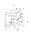
- a hatchback type vehicle10 with a tail gate (not shown) mounted in an openable and closable manner includes, on a lateral side of a vehicle body 11, a side panel 21 covering a side part of the vehicle body 11, a fender panel (front fender panel) 22 covering a front section of the side part of the vehicle body 11, and a triangular fixed window (corner window glass) 23 mounted on the side panel 21.
- the triangular fixed window (corner window glass) 23 is attached to an upper front end part of an outside panel 26, and a protrusion 76 is formed at an upper edge 22a of the fender panel 22 (more specifically, a part of the upper edge 22a closer to a center in a longitudinal direction of the vehicle body).
- the protrusion 76 has a flange 77 extending therefrom toward and along an inner surface 23a of the fixed window 23, and a clip 68 having a slit 97 formed at a position corresponding to the flange 77 and extending in the longitudinal direction of the vehicle body is attached to the upper front end part of the outside panel 26.
- the upper edge 22a, or a rear end, of the fender panel 22 is fixed to the upper front end part of the outside panel 26.
- the upper front end part of the outside panel 26 is corresponding to an opening edge (window frame) 58 of a front pillar outer member 51 which will be described later.
- the side panel 21 is composed of an inner side panel 25 disposed on a cabin 12 side, and an outer side panel or outside panel 26 disposed on an outer side of the vehicle.
- the inner side panel 25 includes a front pillar inner member 41, a roof rail inner member 42, a center pillar inner member 43, a side sill inner member 44, and a rear pillar inner member 45.
- the outside panel 26 includes the front pillar outer member 51, a roof rail outer member 52, a center pillar outer member 53, a side sill outer member 54, a rear pillar outer member 55, and a rear fender panel 56.
- the front pillar inner member 41 and the front pillar outer member 51 together form a front pillar 31.
- the roof rail inner member 42 and the roof rail outer member 52 together form a roof rail 32.
- the center pillar inner member 43 and the center pillar outer member 53 together form a center pillar 33.
- the side sill inner member 44 and the side sill outer member 54 together form a side sill 34.
- the rear pillar inner member 45 and the rear pillar outer member 55 together form a rear pillar 35.
- the front pillar outer member 51 includes the opening edge (window frame) 58 formed in an upper part thereof, and a vertical part 59 formed below the opening edge 58.
- the opening edge 58 is formed by a front frame member 61 extending upward, a rear frame member 62 extending upward, an upper frame member 63 extending obliquely forward and downward from an upper end of the rear frame member 62, and a lower frame member 64 extending substantially horizontally in the longitudinal direction of the vehicle body.
- the opening edge 58 of the fixed window 23, i.e. the opening edge 58 of the front pillar outer member 51, has a recess 67 formed on a front part thereof (more specifically, on the front frame member 61 of the opening edge 58 to which the fixed window 23 is fixed) to bulge inward in a vehicle width direction at a position facing the inner surface 23a of the fixed window 23.
- the clip 68 is fitted into the recess 67 with a periphery 68a thereof being positioned.
- the recess 67 has a clip hole 69 formed therein for fixing the clip 68.
- the recess 67 is formed in a clip mount section of the outside panel 26 to bulge inward in the vehicle width direction, i.e. toward the cabin 12 side, and the clip 68 is mounted in such a manner to be fitted along edges 67a, 67b of the recess 67.
- the clip 68 would be turned or displaced by traveling vibration and the like without additionally providing a boss or the like.
- the protrusion 76 of the fender panel 22 can be easily fixed, resulting in improved work efficiency.
- the flange 77 of the fender panel 22 is firmly supported, so that vibration and noise generated from a vicinity of the protrusion 76 can be suppressed.
- a fixed window supporting section 71 for supporting the fixed window 23 is formed on an inner part of the opening edge 58, and a plurality of window glass fixing holes 72 for attachment of the fixed window 23 are formed in the fixed window supporting section 71.
- Window glass fixing clips 73 are provided on the fixed window 23 to be mated with the window glass fixing holes 72.
- the fixed window supporting section 71 is corresponding to a periphery of the opening edge (window frame) 58.
- the lower frame member 64 is located at the same position as an upper end 59a of the vertical part 59.
- the fixed window 23 is located below the front pillar 31 and joined to the outside panel 26 via a seal member (elastic body) 74 (see Fig. 10 ). More specifically, the window glass fixing clips 73 (different from the clip 68) are bonded on the inner surface 23a of the fixed window (corner window glass) 23 at three corners, and the fixed window 23 is fixed by fitting the window glass fixing clips 73 into the window glass fixing holes 72 in the outside panel 26. Further, black ceramic coating is applied on a periphery 23b of the fixed window (corner window glass) 23, and the window glass fixing clips 73 are thereby masked so as not to be visible from outside the vehicle.
- the inner surface 23a of the fixed window (corner window glass) 23 faces toward the cabin 12 side.
- the fender panel 22 covers a lateral side surface of a front part of the vehicle body 11 and a front section 27a of the outer surface 27 of the outside panel 26.
- the fender panel 22 includes a fender body 75 covering the lateral side surface of the front part of the vehicle body 11, the protrusion 76 formed at the upper edge 22a of the fender panel 22, the flange 77 extending from a side edge 76a of the protrusion 76 facing the fixed window 23, and a plurality of mounting flanges 78a to 78f for attachment to the vehicle body 11.
- the front section 27a includes a lower end 63a of the upper frame member 63.
- the protrusion 76 is formed on a longitudinal middle section of the upper edge 22a of the fender panel 22 so as to cover the lower end 63a of the upper frame member 63 forming a part of the front pillar 31 (more specifically, the front pillar outer member 51).
- the protrusion 76 may be formed to extend from a rear end of the upper edge 22a of the fender panel 22, not only from the longitudinal middle section of the upper edge 22a.
- the flange 77 extends from the side edge 76a of the protrusion 76 facing the fixed window 23 toward and along the inner surface 23a of the fixed window 23. Further, the flange 77 has a projection 81 formed to project outward in the vehicle width direction, and reinforcing beads 82, 82 formed adjacent to a base 76b of the protrusion 76.
- the projection 81 forms an engagement part for engagement with the clip 68, more specifically, with an opening 111 of the clip 68 which will be described later.
- the projection 81 has a bowl-shaped cross section, and formed in a regular hexagonal shape in a side view.
- the projection 81 may be formed in a circular or elliptical shape in a side view.
- the flange 77 has the projection 81 formed on the engagement part for engagement with the clip 68 and projecting outward in the vehicle width direction, and the clip 68 has the opening 111 for engagement with the projection 81, whereby the projection 81 of the flange 77 and the opening 111 of the clip 68 are engaged with each other.
- the flange 77 Since the flange 77 has the reinforcing beads 82, 82 formed thereon adjacent to the base 76b of the protrusion 76, the strength of the flange 77 is increased. The flange 77 can therefore be prevented from being vibrated by traveling vibration and the like, and thus vibration and noise generated from the vicinity of the protrusion 76 can be suppressed. Further, during repair operation of the fender panel 22, the protrusion 76 can be easily fixed, resulting in improved work efficiency.
- the fender panel 22 With the mounting flanges 78a to 78f ( Figs. 6 , 7 ) formed on a periphery of the fender panel 22 at predetermined intervals, the fender panel 22 is fixedly mounted on the vehicle body 11 via bolts.
- the fender panel 22 has the protrusion 76 formed so as to cover the lower end 63a of the front pillar 31 (i.e., upper frame member 63) of the outside panel 26 from outside in the vehicle width direction.
- the protrusion 76 extends from the longitudinal middle section of the upper edge 22a of the fender panel 22 along the front pillar 31.
- the fender panel 22 includes the projection 81 formed to project outward in the vehicle width direction at a position corresponding to the clip 68 mounted on the outside panel 26. After the fender panel 22 is mounted, the projection 81 is engaged with the opening 111 of the clip 68, whereby a restriction in the longitudinal direction, the width direction, and a vertical direction of the vehicle body can be realized at a single section. As a result, it is possible to ensure easy positioning capability and good fitting stability.
- the clip (clip assembly) 68 includes a clip body 91 for clamping the fender panel 22, a rivet 92 for attaching the clip body 91 to the outside panel 26, and a collar 93 fitted to the clip body 91.
- the clip body 91 is formed of resin.
- the rivet 92 and the collar 93 are formed of metal.
- the rivet 92 is preferably formed of aluminum.
- the clip body 91 is attached to the recess 67 formed on the opening edge 58 ( Fig. 5 ) of the outside panel 26.
- the clip body 91 has an inner base 94 located inward to face the outside panel 26, an outer base 95 located outward to face the fixed window 23, a connecting part 96 formed to connect the inner base 94 and the outer base 95, and a substantially U-shaped slit 97 formed by the inner base 94 and the outer base 95.
- the inner base 94 is a portion to be fitted into the recess 67 of the opening edge 58 ( Fig. 5 ).
- the inner base 94 has a through hole 101 for passage therethrough the rivet 92 and the collar 93, ridges 102, 102 that come into contact with the flange 77 on the side facing the outside panel 26, a slope 103 for allowing the flange 77 to be slid easily, a plurality of legs 104 that come into contact with the recess 67, and a ring 105 that comes into contact with the recess 67.
- the ridges 102, 102 are formed on the inner base 94 to face and project toward the outer base 95.
- the ridges 102, 102 are supporting portions for preventing a backlash of the flange 77 in the vehicle width direction.
- the slope 103 is formed from an end 94a of the inner base 94 on the side adjacent to the fender panel 22 to ends 102a, 102a of the ridges 102, 102 on the side adjacent to the fender panel 22 so as to have an inclined or beveled edge.
- the slope 103 serves to allow the flange 77 to be inserted smoothly into the slit 97.
- the legs 104 are formed on the inner base 94 at four corners on a surface facing the outside panel 26.
- the ring 105 is formed around the through hole 101 on the surface facing the outside panel 26.
- the connecting part 96 has a vertical rib 107 and a plurality of horizontal ribs 108 for reinforcing the connecting part 96.
- the outer base 95 has the opening 111 for allowing the rivet 92 to be inserted therethrough, ridges 112, 112 that come into contact with the flange 77 on the side facing the fixed window 23, a slope 113 for allowing the flange 77 to be slid easily, and a base-side rib 114 for reinforcing the outer base 95.
- the opening 111 is not only an insertion hole through which the rivet 92 is inserted when the clip 68 is fixed to the outside panel 26, but also an engagement hole for engagement with the projection 81 of the flange 77.
- the base-side rib 114 includes vertical ribs 116a, 116b, horizontal ribs 117a, 117b, 117b, and a ring-shaped rib 119.
- the slope 113 of the outer base 95 serves to allow the flange 77 to be inserted smoothly into the slit 97 in cooperation with the slope 103 of the inner base 94.
- the ridges 112, 112 are formed on the outer base 95 to face and project toward the inner base 94.
- the ridges 112, 112 are supporting portions for preventing a backlash of the flange 77 in the vehicle width direction.
- the rivet 92 is composed of a rivet body 121 that penetrates through the collar 93 and the clip hole 69 ( Fig. 5 ) of the recess 67, and a pin 122 that penetrates through the rivet body 121.
- the rivet body 121 has a flange part 124 ( Fig. 10 ) formed to be in contact with the inner base 94 and an end of the collar 93, and a cylindrical part 125 passing through the through hole 101 and the clip hole 69.
- the pin 122 has a pin body 126 passing through the cylindrical part 125, and an expansion part or head 127 formed at one end of the pin body 126.
- the collar 93 has a collar flange part 128 formed to be in contact with the recess 67, and a collar cylindrical part 129 extending from the collar flange part 128 to be in contact with the flange part 124 of the rivet body 121.
- the collar 93 is inserted into the through hole 101 of the inner base 94, and serves to prevent the inner base 94, which is formed of resin, from being collapsed and reduced in thickness when caulking the rivet 92.
- the pin 122 is pulled using a dedicated tool (not shown) outward of the vehicle body, whereby the cylindrical part 125 of the rivet body 121 is deformed and the clip body 91 is fastened to the recess 67. A surplus portion of the pin body 126 projecting from the flange part 124 of the rivet body 121 is then removed, and the caulking is completed as shown in Fig. 10 .
- the opening edge 58 of the fixed window 23 (more precisely, the opening edge 58 on which the fixed window 23 is mounted) is provided with the clip 68 having the slit 97 formed at the position corresponding to the flange 77 and extending in the longitudinal direction of the vehicle body, and the flange 77 is detachably engaged with the slit 97 of the clip 68 to thereby lock the protrusion 76 to the opening edge 58 of the fixed window 23, as shown in Figs. 2 , 10 , and 11 .
- the clip 68 is formed in a substantially U shape opened forward of the vehicle, and having the slit 97 extending in the longitudinal direction of the vehicle body in a state of being attached.
- the flange 77 is detachably engaged with the slit 97, thereby fixing the protrusion 76 of the fender panel 22.
- a fixing section of the protrusion 76 can be arranged inward of the fixed window (corner window glass) 23. There is no need to provide an additional member such as a garnish.
- the fixing section can be made invisible by applying black ceramic coating on the periphery 23b ( Fig. 3 ) of the fixed window 23, and an improved outer appearance can thus be obtained.
- the protrusion 76 can be easily fixed without causing breakage of the clip 68 even if repair and maintenance operation of the fender panel 22 is performed a plurality of times, and thus the work efficiency can be improved.
- the protrusion 76 can be securely fixed in this manner without using a foamed material, so that vibration and noise generated from the vicinity of the protrusion 76 can be suppressed.
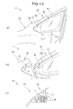
- Figs. 13(a) to 13(c) show processes for detaching and attaching the fender panel 22.
- bolts (not shown) are removed from the mounting flanges 78a to 78f ( Figs. 6 , 7 ) formed on the periphery of the fender panel 22 at predetermined intervals.
- the fender panel 22 is slid forward of the vehicle body as indicated by arrow b1 while being pulled outward of the vehicle body.
- the flange 77 of the protrusion 76 of the fender panel 22 is detached from the slit 97 ( Fig. 11 ) of the clip 68 of the outside panel 26 (or, the projection 81 of the flange 77 is disengaged from the opening 111 of the clip 68), and the fender panel 22 is released.
- the fender panel 22 can be easily detached without detaching the fixed window (corner window glass) 23 mounted on the outside panel 26.
- Fig. 13(c) the fender panel 22 is attached in a reverse process to the one shown in Fig. 13(b) .
- the flange 77 is inserted along the inner surface 23a ( Fig. 13(b) ) of the fixed window 23, and the mounting flanges 78a to 78f ( Figs. 6 , 7 ) formed on the periphery of the fender panel 22 at predetermined intervals are fixed to the vehicle body 11 ( Fig. 13(a) ) via the bolts (not shown).
- the projection 81 of the flange 77 is engaged with the opening 111 of the clip 68, thereby easily positioning the flange 77, and the restriction in the longitudinal direction, the width direction, and the vertical direction of the vehicle body can be realized at the single section, thereby ensuring good fitting stability.
- the vehicle 10 includes the triangular fixed window 23 located below the front pillar 31 and joined to the outside panel 26.
- the fender panel 22, which covers the front section 27a of the outer surface 27 of the outside panel 26, has the protrusion 76 formed at the upper edge 22a thereof so as to cover the lower end 63a of the upper frame member 63 forming the front pillar 31 (front pillar outer member 51).
- the protrusion 76 has the flange 77 extending toward and along the inner surface 23a of the fixed window 23, and the opening edge 58 of the fixed window 23 (the opening edge 58 on which the fixed window 23 is mounted) is provided with the clip 68 having the slit 97 formed at the position corresponding to the flange 77 and extending in the longitudinal direction of the vehicle.
- the flange 77 is detachably engaged with the slit 97 of the clip 68 to thereby lock the protrusion 76 to the opening edge 58 of the fixed window 23.
- the fixing section of the protrusion 76 can be arranged inward of the fixed window 23, and thus there is no need to provide an additional member such as a garnish.
- the fixing section can be made invisible by applying black ceramic coating on the periphery 23b of the fixed window 23, and an improved outer appearance can thus be obtained.
- the protrusion 76 can be easily fixed without causing breakage of the clip 68 even if repair and maintenance operation of the fender panel 22 is performed a plurality of times, and thus the work efficiency can be improved.
- the protrusion 76 can be securely fixed in this manner without using a formed material, so that vibration and noise generated from the vicinity of the protrusion 76 can be suppressed.
- the flange 77 has the projection 81 projecting outward in the vehicle width direction
- the clip 68 has the opening 111 for engagement with the projection 81.
- the protrusion 76 of the fender panel 22 can be fixed more easily, and thus the work efficiency can be further improved. Since the fender panel 22 can be securely fixed in this manner, vibration and noise generated from the vicinity of the protrusion 76 can be further suppressed.
- the opening edge 58 of the fixed window 23 (the opening edge 58 on which the fixed window 23 is mounted) has the recess 67 formed on the front part thereof, and the clip 68 is fitted into the recess 67.
- the protrusion 76 can be fixed more easily with no fear that the clip 68 would be turned or displaced by traveling vibration and the like. As a result, it is possible to further improve the work efficiency, while further suppressing vibration and noise generated from the vicinity of the protrusion 76.
- the flange 77 has the reinforcing beads 82, 82 formed thereon adjacent to the base 76b of the protrusion 76 (formed from the base 76b of the protrusion 76 to the flange 77) for increasing the strength of the flange 77, the flange 77 can be prevented from being vibrated by traveling vibration and the like, and thus vibration and noise generated from the vicinity of the protrusion 76 can be further suppressed. Moreover, during repair operation of the fender panel 22, the protrusion 76 can be fixed more easily, and thus the work efficiency can be further improved.
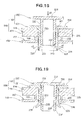
- Figs. 14 to 19 show a vehicle fender panel mounting structure according to the second embodiment.
- a resin grommet 192 is provided in place of the rivet 92 in the one of the first embodiment shown in Fig. 10 .
- Parts that are the same as in the first embodiment are indicated by the same reference characters, and a detailed description thereof will be hereinafter omitted.
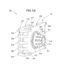
- a clip (clip assembly) 168 includes a clip body 191 for clamping the fender panel 22, and the grommet 192 for attaching the clip body 191 to an outside panel 166.
- the clip body 191 and the grommet 192 are formed of resin.
- the clip body 191 is attached to a recess 167 formed on the outside panel 166.
- the clip 168 is mounted in such a manner to be fitted along edges 167a, 167b of the recess 167, whereby a periphery 168a of the clip 168 is positioned within the recess 167.
- the clip body 191 has an inner base 194 located inward to face the outside panel 166, an outer base 195 located outward to face the fixed window 23, a connecting part 196 formed to connect the inner base 194 and the outer base 195, and a substantially U-shaped slit 197 formed by the inner base 194 and the outer base 195.
- the inner base 194 is a portion to be fitted into the recess 167.
- the inner base 194 has a through hole 201 for passage therethrough the grommet 192, ridges 202, 202 that come into contact with the flange 77 on the side facing the outside panel 166, a slope 203 for allowing the flange 77 to be slid easily, a plurality of legs 204 that come into contact with the recess 167, and a ring 205 that comes into contact with the recess 167.
- the ridges 202, 202 are formed on the inner base 194 to face and project toward the outer base 195.
- the ridges 202, 202 are supporting portions for preventing a backlash of the flange 77 in the vehicle width direction.
- the slope 203 is formed from an end 194a of the inner base 194 on the side adjacent to the fender panel 22 to ends 202a, 202a of the ridges 202, 202 on the side adjacent to the fender panel 22 so as to have an inclined or beveled edge.
- the slope 203 serves to allow the flange 77 to be inserted smoothly into the slit 97.
- the legs 204 are formed on the inner base 194 at four corners on a surface facing the outside panel 166.
- the ring 205 is formed around the through hole 201 on the surface facing the outside panel 166.
- the connecting part 196 has a vertical rib 207 and a plurality of horizontal ribs 208 for reinforcing the connecting part 196.
- the outer base 195 has an opening 211 for allowing the grommet 192 to be inserted therethrough, ridges 212, 212 that come into contact with the flange 77 on the side facing the fixed window 23, a slope 213 for allowing the flange 77 to be slid easily, and a base-side rib 214 for reinforcing the outer base 195.
- the opening 211 is not only an insertion hole through which the grommet 192 is inserted when the clip 168 is fixed to the outside panel 166, but also an engagement hole for engagement with the projection 81 of the flange 77.
- the base-side rib 214 includes vertical ribs 216a, 216b, horizontal ribs 217a, 217b, 217b, and a ring-shaped rib 219.
- the slope 213 of the outer base 195 serves to allow the flange 77 to be inserted smoothly into the slit 197 in cooperation with the slope 203 of the inner base 194.
- the ridges 212, 212 are formed on the outer base 195 to face and project toward the inner base 194.
- the ridges 212, 212 are supporting portions for preventing a backlash of the flange 77 in the vehicle width direction.
- the grommet 192 is composed of an outer cylindrical part (housing part) 221 that passes through the through hole 201 of the inner base 194, and an inner cylindrical part (pin part) 222 fitted in the outer cylindrical part 221.
- the outer cylindrical part 221 has a flange part 224 formed to be in contact with the inner base 194, an outer cylindrical body 225 passing through the through hole 201, and an expansion part 226 formed at an end of the outer cylindrical body 225 to be locked to a clip hole 169 ( Fig. 14 ) of the recess 167.
- the expansion part 226 has a plurality of cuts 227 formed along a circumference direction, and a plurality of locking pieces 228 formed by the cuts 227.
- Each of the locking pieces 228 has a projection 229 ( Figs. 18, 19 ) formed on an inner surface adjacent to a tip end thereof.
- the inner cylindrical part 222 has a head 231 for pressing the inner cylindrical part 222, an inner cylindrical body 232 extending from the head 231, a locking groove 233 formed adjacent to a tip end of the inner cylindrical body 232, and a tapered edge 234 formed at the tip end of the inner cylindrical body 232.
- the head 231 of the inner cylindrical part 222 is pressed as indicated by arrow a1.
- the projection 229 of the outer cylindrical part 221 is pushed by the tapered edge 234 of the inner cylindrical part 222 outward in a radial direction as indicated by arrows a2, a2.
- the clip 168 is attached to the recess 167 of the outside panel 166, as shown in Fig. 19 , with the grommet 192 is brought into a locked state out of a non-locked state.
- a vehicle fender panel mounting structure includes a clip 248 having a clip body 251, and a locking claw 252 formed of resin integrally with the clip body 251 for attaching the clip body 251 to an outside panel 266.
- the clip 248 has an inner base 254 located inward to face the outside panel 266, an outer base 255 located outward to face the fixed window 23 ( Fig. 2 ), a connecting part 256 formed to connect the inner base 254 and the outer base 255, a substantially U-shaped slit 257 formed by the inner base 254 and the outer base 255, and the locking claw 252 for attachment with the outside panel 266.
- the inner base 254, the outer base 255, the connecting part 256, and the slit 257 of the clip 248 have substantially the same configuration as those of the clip body 191 ( Fig. 15 ) of the second embodiment.
- the inner base 254 has a locking claw base 259 formed in a circular shape, and the locking claw 252 formed on the locking claw base 259 to be attached with a recess 267 formed on the outside panel 266.
- the recess 267 of the outside panel 266 has a substantially rectangular clip hole 269 formed therein to be locked with the locking claw 252.
- the clip 248 has the clip body 251 and the locking claw 252 which are integrally formed of resin, and is fixedly attached to the recess 267 of the outside panel 266 via the locking claw 252.
- the clip 248 is formed in a substantially U shape opened forward of the vehicle, and having the slit 257 extending in the longitudinal direction of the vehicle body in a state of being attached.
- the flange 77 ( Fig. 2 ) is detachably engaged with the slit 257, thereby fixing the protrusion 76 of the fender panel 22.
- the vehicle fender panel mounting structure according to the present invention has been described above in relation to the cases where the clip 68 having the rivet 92 for attaching the clip body 91 to the outside panel 26 is used as shown in Figs. 10 to 12 (Embodiment 1), where the clip 168 having the grommet 192 for attaching the clip body 191 to the outside panel 166 is used as shown in Figs. 14 to 19 (Embodiment 2), and where the clip 248 having the clip body 251 and the locking claw 252 that are integrally formed of resin is used as shown in Fig. 20 (Embodiment 3).
- the present invention is not so limited, and aspects of these embodiments may be combined or modified as appropriate.
- the vehicle fender panel mounting structure of the present invention is well suited for use in passenger vehicles such as sedan cars, wagon cars, etc.
Landscapes
- Engineering & Computer Science (AREA)
- Mechanical Engineering (AREA)
- Chemical & Material Sciences (AREA)
- Combustion & Propulsion (AREA)
- Transportation (AREA)
- Body Structure For Vehicles (AREA)
- Connection Of Plates (AREA)
Applications Claiming Priority (2)
| Application Number | Priority Date | Filing Date | Title |
|---|---|---|---|
| JP2012009802 | 2012-01-20 | ||
| PCT/JP2012/080915 WO2013108494A1 (ja) | 2012-01-20 | 2012-11-29 | 車両のフェンダパネル取付構造 |
Publications (3)
| Publication Number | Publication Date |
|---|---|
| EP2805876A1 true EP2805876A1 (de) | 2014-11-26 |
| EP2805876A4 EP2805876A4 (de) | 2015-09-30 |
| EP2805876B1 EP2805876B1 (de) | 2016-09-28 |
Family
ID=48798931
Family Applications (1)
| Application Number | Title | Priority Date | Filing Date |
|---|---|---|---|
| EP12865580.0A Not-in-force EP2805876B1 (de) | 2012-01-20 | 2012-11-29 | Kotflügelmontagestruktur für ein fahrzeug |
Country Status (6)
| Country | Link |
|---|---|
| US (1) | US8979166B2 (de) |
| EP (1) | EP2805876B1 (de) |
| JP (1) | JPWO2013108494A1 (de) |
| CN (1) | CN104203729B (de) |
| BR (1) | BR112014017786A8 (de) |
| WO (1) | WO2013108494A1 (de) |
Cited By (1)
| Publication number | Priority date | Publication date | Assignee | Title |
|---|---|---|---|---|
| EP3599146A1 (de) * | 2018-07-27 | 2020-01-29 | NOVARES France | Anschlusshaken für spoiler |
Families Citing this family (14)
| Publication number | Priority date | Publication date | Assignee | Title |
|---|---|---|---|---|
| JP5903087B2 (ja) * | 2013-10-24 | 2016-04-13 | 本田技研工業株式会社 | スプリングクリップ、および自動車のフェンダパネルの取り付け構造 |
| USD746743S1 (en) * | 2014-11-12 | 2016-01-05 | Ford Motor Company | Vehicle fender |
| CN104443059A (zh) * | 2014-12-05 | 2015-03-25 | 无锡同捷汽车设计有限公司 | 汽车翼子板下部安装结构 |
| JP6653602B2 (ja) * | 2016-03-18 | 2020-02-26 | ベバスト ジャパン株式会社 | パネル構造体、及びその製造方法 |
| JP6401760B2 (ja) * | 2016-09-15 | 2018-10-10 | 本田技研工業株式会社 | 車体構造 |
| JP6684037B2 (ja) * | 2017-01-20 | 2020-04-22 | 本田技研工業株式会社 | 車体前部構造 |
| JP6517859B2 (ja) * | 2017-02-28 | 2019-05-22 | 本田技研工業株式会社 | 車体フロア構造 |
| DE102017104237A1 (de) * | 2017-03-01 | 2018-09-06 | Dr. Ing. H.C. F. Porsche Aktiengesellschaft | Radlauf mit einer Radlaufblende |
| USD881757S1 (en) * | 2018-03-02 | 2020-04-21 | Ford Global Technologies, Llc | Vehicle exterior |
| USD873742S1 (en) * | 2018-10-29 | 2020-01-28 | Honda Motor Co., Ltd. | Vehicle fender |
| JP6928069B2 (ja) * | 2019-11-28 | 2021-09-01 | 本田技研工業株式会社 | 車両前部構造 |
| US11772711B2 (en) * | 2020-08-07 | 2023-10-03 | Fontaine Spray Suppression Company | Fender support arm with bolt-retaining strip |
| JP2023066152A (ja) * | 2021-10-28 | 2023-05-15 | 本田技研工業株式会社 | フェンダパネル取付構造 |
| CN115366996B (zh) * | 2022-08-09 | 2023-06-23 | 岚图汽车科技有限公司 | 一种安装支架及翼子板安装组件 |
Family Cites Families (14)
| Publication number | Priority date | Publication date | Assignee | Title |
|---|---|---|---|---|
| JPS6089074A (ja) | 1983-10-20 | 1985-05-18 | Toppan Printing Co Ltd | 燃料電池用電解質タイルの製造方法 |
| JPS60111737A (ja) * | 1983-11-22 | 1985-06-18 | Mazda Motor Corp | エンジン用シリンダボア中子の造型法 |
| JPS6089074U (ja) * | 1983-11-25 | 1985-06-18 | マツダ株式会社 | 自動車の前部車体構造 |
| JP3413284B2 (ja) | 1994-07-07 | 2003-06-03 | 本田技研工業株式会社 | フロントフェンダの補強構造 |
| JP2724806B2 (ja) * | 1994-09-12 | 1998-03-09 | 本田技研工業株式会社 | 自動車の前部車体構造 |
| JP4140078B2 (ja) | 1998-03-05 | 2008-08-27 | マツダ株式会社 | 車両のウィンドガラス構造 |
| JP3532420B2 (ja) | 1998-09-22 | 2004-05-31 | ダイハツ工業株式会社 | 自動車のフロントフェンダ取付け構造 |
| JP4206878B2 (ja) | 2003-09-22 | 2009-01-14 | トヨタ車体株式会社 | 自動車のフェンダパネルの取付構造 |
| JP4405327B2 (ja) * | 2004-06-30 | 2010-01-27 | 本田技研工業株式会社 | フロントフェンダ構造 |
| JP2006213295A (ja) | 2005-02-07 | 2006-08-17 | Honda Motor Co Ltd | フロントフェンダの補強構造 |
| EP1854705B1 (de) * | 2006-05-10 | 2009-07-15 | Mazda Motor Corporation | Fahrzeugaufbaukonstruktion |
| JP4778936B2 (ja) * | 2007-06-22 | 2011-09-21 | 株式会社豊田自動織機 | 自動車におけるピラー部構造 |
| JP5125300B2 (ja) * | 2007-08-08 | 2013-01-23 | トヨタ車体株式会社 | 自動車の固定窓構造 |
| JP5029499B2 (ja) | 2008-06-10 | 2012-09-19 | トヨタ車体株式会社 | 乗用車におけるフェンダパネル固定構造 |
-
2012
- 2012-11-29 US US14/373,141 patent/US8979166B2/en active Active
- 2012-11-29 CN CN201280071598.2A patent/CN104203729B/zh active Active
- 2012-11-29 WO PCT/JP2012/080915 patent/WO2013108494A1/ja active Application Filing
- 2012-11-29 EP EP12865580.0A patent/EP2805876B1/de not_active Not-in-force
- 2012-11-29 JP JP2013554196A patent/JPWO2013108494A1/ja active Pending
- 2012-11-29 BR BR112014017786A patent/BR112014017786A8/pt not_active Application Discontinuation
Cited By (2)
| Publication number | Priority date | Publication date | Assignee | Title |
|---|---|---|---|---|
| EP3599146A1 (de) * | 2018-07-27 | 2020-01-29 | NOVARES France | Anschlusshaken für spoiler |
| FR3084324A1 (fr) * | 2018-07-27 | 2020-01-31 | Novares France | Crochet de connexion pour becquet |
Also Published As
| Publication number | Publication date |
|---|---|
| EP2805876A4 (de) | 2015-09-30 |
| WO2013108494A1 (ja) | 2013-07-25 |
| US20140367997A1 (en) | 2014-12-18 |
| US8979166B2 (en) | 2015-03-17 |
| BR112014017786A8 (pt) | 2017-07-11 |
| EP2805876B1 (de) | 2016-09-28 |
| BR112014017786A2 (de) | 2017-06-20 |
| CN104203729B (zh) | 2016-03-02 |
| JPWO2013108494A1 (ja) | 2015-05-11 |
| CN104203729A (zh) | 2014-12-10 |
Similar Documents
| Publication | Publication Date | Title |
|---|---|---|
| EP2805876B1 (de) | Kotflügelmontagestruktur für ein fahrzeug | |
| JP6817818B2 (ja) | クリップ及びドアトリムの取り付け構造 | |
| JP4076940B2 (ja) | ガーニッシュの取付け構造及び取付け方法 | |
| JP6359497B2 (ja) | エンドキャップ付きベルトモール | |
| JP6401767B2 (ja) | 車体構造 | |
| CN109383406B (zh) | 车门装饰件结构 | |
| JP6545730B2 (ja) | ドアフレームモールの取り付け構造 | |
| WO2010052834A1 (ja) | ピラーガーニッシュの取付構造 | |
| CN106476573B (zh) | 用于固定车辆三角玻璃的结构 | |
| JP2009073409A (ja) | 自動車用バイザー | |
| JP2007314067A (ja) | ピラーガーニッシュの上部合わせ構造 | |
| JP5307526B2 (ja) | ガラスランの取付構造 | |
| KR20190057781A (ko) | 도어의 웨더스트립 체결구조 | |
| JP2007296998A (ja) | カウルトップカバー | |
| US8628129B2 (en) | Connection module | |
| EP1798113A2 (de) | Clipbefestigungsanordnung für ein Fahrzeugverkleidungsteil | |
| JP4716863B2 (ja) | 自動車におけるメータクラスタ取付装置 | |
| CN108001377B (zh) | 车辆用内饰件的固定构造 | |
| JP2020029159A (ja) | 見切りシール取付構造 | |
| CN218031001U (zh) | 索环 | |
| JP2018111388A (ja) | ガーニッシュ固定構造 | |
| JP4497071B2 (ja) | 車両のピラーガーニッシュの取付構造 | |
| JP5315541B2 (ja) | 車両用インストルメントパネルの取付構造 | |
| JP2023113412A (ja) | 車両用サイドドア | |
| JP6472736B2 (ja) | ウインドデフレクタの取付構造 |
Legal Events
| Date | Code | Title | Description |
|---|---|---|---|
| PUAI | Public reference made under article 153(3) epc to a published international application that has entered the european phase |
Free format text: ORIGINAL CODE: 0009012 |
|
| 17P | Request for examination filed |
Effective date: 20140811 |
|
| AK | Designated contracting states |
Kind code of ref document: A1 Designated state(s): AL AT BE BG CH CY CZ DE DK EE ES FI FR GB GR HR HU IE IS IT LI LT LU LV MC MK MT NL NO PL PT RO RS SE SI SK SM TR |
|
| RIN1 | Information on inventor provided before grant (corrected) |
Inventor name: KATSUMATA, KOUSUKE Inventor name: ISEKI, MASASHIGE Inventor name: YAMANAKA, HIROKI Inventor name: MASUTA, NORIAKI |
|
| DAX | Request for extension of the european patent (deleted) | ||
| RA4 | Supplementary search report drawn up and despatched (corrected) |
Effective date: 20150828 |
|
| RIC1 | Information provided on ipc code assigned before grant |
Ipc: B62D 25/04 20060101ALI20150824BHEP Ipc: B62D 25/16 20060101AFI20150824BHEP |
|
| GRAP | Despatch of communication of intention to grant a patent |
Free format text: ORIGINAL CODE: EPIDOSNIGR1 |
|
| RIC1 | Information provided on ipc code assigned before grant |
Ipc: B62D 25/04 20060101ALI20160321BHEP Ipc: B62D 25/16 20060101AFI20160321BHEP |
|
| INTG | Intention to grant announced |
Effective date: 20160420 |
|
| GRAS | Grant fee paid |
Free format text: ORIGINAL CODE: EPIDOSNIGR3 |
|
| GRAA | (expected) grant |
Free format text: ORIGINAL CODE: 0009210 |
|
| AK | Designated contracting states |
Kind code of ref document: B1 Designated state(s): AL AT BE BG CH CY CZ DE DK EE ES FI FR GB GR HR HU IE IS IT LI LT LU LV MC MK MT NL NO PL PT RO RS SE SI SK SM TR |
|
| REG | Reference to a national code |
Ref country code: GB Ref legal event code: FG4D |
|
| REG | Reference to a national code |
Ref country code: CH Ref legal event code: EP |
|
| REG | Reference to a national code |
Ref country code: AT Ref legal event code: REF Ref document number: 832466 Country of ref document: AT Kind code of ref document: T Effective date: 20161015 |
|
| REG | Reference to a national code |
Ref country code: IE Ref legal event code: FG4D |
|
| REG | Reference to a national code |
Ref country code: DE Ref legal event code: R096 Ref document number: 602012023632 Country of ref document: DE |
|
| REG | Reference to a national code |
Ref country code: LT Ref legal event code: MG4D |
|
| PG25 | Lapsed in a contracting state [announced via postgrant information from national office to epo] |
Ref country code: LT Free format text: LAPSE BECAUSE OF FAILURE TO SUBMIT A TRANSLATION OF THE DESCRIPTION OR TO PAY THE FEE WITHIN THE PRESCRIBED TIME-LIMIT Effective date: 20160928 Ref country code: RS Free format text: LAPSE BECAUSE OF FAILURE TO SUBMIT A TRANSLATION OF THE DESCRIPTION OR TO PAY THE FEE WITHIN THE PRESCRIBED TIME-LIMIT Effective date: 20160928 Ref country code: FI Free format text: LAPSE BECAUSE OF FAILURE TO SUBMIT A TRANSLATION OF THE DESCRIPTION OR TO PAY THE FEE WITHIN THE PRESCRIBED TIME-LIMIT Effective date: 20160928 Ref country code: NO Free format text: LAPSE BECAUSE OF FAILURE TO SUBMIT A TRANSLATION OF THE DESCRIPTION OR TO PAY THE FEE WITHIN THE PRESCRIBED TIME-LIMIT Effective date: 20161228 Ref country code: HR Free format text: LAPSE BECAUSE OF FAILURE TO SUBMIT A TRANSLATION OF THE DESCRIPTION OR TO PAY THE FEE WITHIN THE PRESCRIBED TIME-LIMIT Effective date: 20160928 |
|
| REG | Reference to a national code |
Ref country code: NL Ref legal event code: MP Effective date: 20160928 |
|
| REG | Reference to a national code |
Ref country code: AT Ref legal event code: MK05 Ref document number: 832466 Country of ref document: AT Kind code of ref document: T Effective date: 20160928 |
|
| PG25 | Lapsed in a contracting state [announced via postgrant information from national office to epo] |
Ref country code: NL Free format text: LAPSE BECAUSE OF FAILURE TO SUBMIT A TRANSLATION OF THE DESCRIPTION OR TO PAY THE FEE WITHIN THE PRESCRIBED TIME-LIMIT Effective date: 20160928 Ref country code: BE Free format text: LAPSE BECAUSE OF NON-PAYMENT OF DUE FEES Effective date: 20161130 Ref country code: GR Free format text: LAPSE BECAUSE OF FAILURE TO SUBMIT A TRANSLATION OF THE DESCRIPTION OR TO PAY THE FEE WITHIN THE PRESCRIBED TIME-LIMIT Effective date: 20161229 Ref country code: SE Free format text: LAPSE BECAUSE OF FAILURE TO SUBMIT A TRANSLATION OF THE DESCRIPTION OR TO PAY THE FEE WITHIN THE PRESCRIBED TIME-LIMIT Effective date: 20160928 Ref country code: LV Free format text: LAPSE BECAUSE OF FAILURE TO SUBMIT A TRANSLATION OF THE DESCRIPTION OR TO PAY THE FEE WITHIN THE PRESCRIBED TIME-LIMIT Effective date: 20160928 |
|
| PG25 | Lapsed in a contracting state [announced via postgrant information from national office to epo] |
Ref country code: RO Free format text: LAPSE BECAUSE OF FAILURE TO SUBMIT A TRANSLATION OF THE DESCRIPTION OR TO PAY THE FEE WITHIN THE PRESCRIBED TIME-LIMIT Effective date: 20160928 Ref country code: EE Free format text: LAPSE BECAUSE OF FAILURE TO SUBMIT A TRANSLATION OF THE DESCRIPTION OR TO PAY THE FEE WITHIN THE PRESCRIBED TIME-LIMIT Effective date: 20160928 |
|
| PG25 | Lapsed in a contracting state [announced via postgrant information from national office to epo] |
Ref country code: ES Free format text: LAPSE BECAUSE OF FAILURE TO SUBMIT A TRANSLATION OF THE DESCRIPTION OR TO PAY THE FEE WITHIN THE PRESCRIBED TIME-LIMIT Effective date: 20160928 Ref country code: IS Free format text: LAPSE BECAUSE OF FAILURE TO SUBMIT A TRANSLATION OF THE DESCRIPTION OR TO PAY THE FEE WITHIN THE PRESCRIBED TIME-LIMIT Effective date: 20170128 Ref country code: CZ Free format text: LAPSE BECAUSE OF FAILURE TO SUBMIT A TRANSLATION OF THE DESCRIPTION OR TO PAY THE FEE WITHIN THE PRESCRIBED TIME-LIMIT Effective date: 20160928 Ref country code: AT Free format text: LAPSE BECAUSE OF FAILURE TO SUBMIT A TRANSLATION OF THE DESCRIPTION OR TO PAY THE FEE WITHIN THE PRESCRIBED TIME-LIMIT Effective date: 20160928 Ref country code: PT Free format text: LAPSE BECAUSE OF FAILURE TO SUBMIT A TRANSLATION OF THE DESCRIPTION OR TO PAY THE FEE WITHIN THE PRESCRIBED TIME-LIMIT Effective date: 20170130 Ref country code: BE Free format text: LAPSE BECAUSE OF FAILURE TO SUBMIT A TRANSLATION OF THE DESCRIPTION OR TO PAY THE FEE WITHIN THE PRESCRIBED TIME-LIMIT Effective date: 20160928 Ref country code: SM Free format text: LAPSE BECAUSE OF FAILURE TO SUBMIT A TRANSLATION OF THE DESCRIPTION OR TO PAY THE FEE WITHIN THE PRESCRIBED TIME-LIMIT Effective date: 20160928 Ref country code: PL Free format text: LAPSE BECAUSE OF FAILURE TO SUBMIT A TRANSLATION OF THE DESCRIPTION OR TO PAY THE FEE WITHIN THE PRESCRIBED TIME-LIMIT Effective date: 20160928 Ref country code: SK Free format text: LAPSE BECAUSE OF FAILURE TO SUBMIT A TRANSLATION OF THE DESCRIPTION OR TO PAY THE FEE WITHIN THE PRESCRIBED TIME-LIMIT Effective date: 20160928 Ref country code: BG Free format text: LAPSE BECAUSE OF FAILURE TO SUBMIT A TRANSLATION OF THE DESCRIPTION OR TO PAY THE FEE WITHIN THE PRESCRIBED TIME-LIMIT Effective date: 20161228 |
|
| REG | Reference to a national code |
Ref country code: DE Ref legal event code: R097 Ref document number: 602012023632 Country of ref document: DE |
|
| PG25 | Lapsed in a contracting state [announced via postgrant information from national office to epo] |
Ref country code: IT Free format text: LAPSE BECAUSE OF FAILURE TO SUBMIT A TRANSLATION OF THE DESCRIPTION OR TO PAY THE FEE WITHIN THE PRESCRIBED TIME-LIMIT Effective date: 20160928 |
|
| REG | Reference to a national code |
Ref country code: CH Ref legal event code: PL |
|
| PG25 | Lapsed in a contracting state [announced via postgrant information from national office to epo] |
Ref country code: DK Free format text: LAPSE BECAUSE OF FAILURE TO SUBMIT A TRANSLATION OF THE DESCRIPTION OR TO PAY THE FEE WITHIN THE PRESCRIBED TIME-LIMIT Effective date: 20160928 Ref country code: LI Free format text: LAPSE BECAUSE OF NON-PAYMENT OF DUE FEES Effective date: 20161130 Ref country code: CH Free format text: LAPSE BECAUSE OF NON-PAYMENT OF DUE FEES Effective date: 20161130 |
|
| PLBE | No opposition filed within time limit |
Free format text: ORIGINAL CODE: 0009261 |
|
| STAA | Information on the status of an ep patent application or granted ep patent |
Free format text: STATUS: NO OPPOSITION FILED WITHIN TIME LIMIT |
|
| GBPC | Gb: european patent ceased through non-payment of renewal fee |
Effective date: 20161228 |
|
| REG | Reference to a national code |
Ref country code: IE Ref legal event code: MM4A |
|
| REG | Reference to a national code |
Ref country code: FR Ref legal event code: ST Effective date: 20170731 |
|
| 26N | No opposition filed |
Effective date: 20170629 |
|
| PG25 | Lapsed in a contracting state [announced via postgrant information from national office to epo] |
Ref country code: LU Free format text: LAPSE BECAUSE OF NON-PAYMENT OF DUE FEES Effective date: 20161130 |
|
| PG25 | Lapsed in a contracting state [announced via postgrant information from national office to epo] |
Ref country code: FR Free format text: LAPSE BECAUSE OF NON-PAYMENT OF DUE FEES Effective date: 20161130 |
|
| PG25 | Lapsed in a contracting state [announced via postgrant information from national office to epo] |
Ref country code: IE Free format text: LAPSE BECAUSE OF NON-PAYMENT OF DUE FEES Effective date: 20161129 Ref country code: GB Free format text: LAPSE BECAUSE OF NON-PAYMENT OF DUE FEES Effective date: 20161228 Ref country code: SI Free format text: LAPSE BECAUSE OF FAILURE TO SUBMIT A TRANSLATION OF THE DESCRIPTION OR TO PAY THE FEE WITHIN THE PRESCRIBED TIME-LIMIT Effective date: 20160928 |
|
| PGFP | Annual fee paid to national office [announced via postgrant information from national office to epo] |
Ref country code: DE Payment date: 20171121 Year of fee payment: 6 |
|
| PG25 | Lapsed in a contracting state [announced via postgrant information from national office to epo] |
Ref country code: HU Free format text: LAPSE BECAUSE OF FAILURE TO SUBMIT A TRANSLATION OF THE DESCRIPTION OR TO PAY THE FEE WITHIN THE PRESCRIBED TIME-LIMIT; INVALID AB INITIO Effective date: 20121129 |
|
| PG25 | Lapsed in a contracting state [announced via postgrant information from national office to epo] |
Ref country code: MC Free format text: LAPSE BECAUSE OF FAILURE TO SUBMIT A TRANSLATION OF THE DESCRIPTION OR TO PAY THE FEE WITHIN THE PRESCRIBED TIME-LIMIT Effective date: 20160928 Ref country code: MK Free format text: LAPSE BECAUSE OF FAILURE TO SUBMIT A TRANSLATION OF THE DESCRIPTION OR TO PAY THE FEE WITHIN THE PRESCRIBED TIME-LIMIT Effective date: 20160928 Ref country code: CY Free format text: LAPSE BECAUSE OF FAILURE TO SUBMIT A TRANSLATION OF THE DESCRIPTION OR TO PAY THE FEE WITHIN THE PRESCRIBED TIME-LIMIT Effective date: 20160928 |
|
| PG25 | Lapsed in a contracting state [announced via postgrant information from national office to epo] |
Ref country code: MT Free format text: LAPSE BECAUSE OF NON-PAYMENT OF DUE FEES Effective date: 20161129 |
|
| PG25 | Lapsed in a contracting state [announced via postgrant information from national office to epo] |
Ref country code: AL Free format text: LAPSE BECAUSE OF FAILURE TO SUBMIT A TRANSLATION OF THE DESCRIPTION OR TO PAY THE FEE WITHIN THE PRESCRIBED TIME-LIMIT Effective date: 20160928 Ref country code: TR Free format text: LAPSE BECAUSE OF FAILURE TO SUBMIT A TRANSLATION OF THE DESCRIPTION OR TO PAY THE FEE WITHIN THE PRESCRIBED TIME-LIMIT Effective date: 20160928 |
|
| REG | Reference to a national code |
Ref country code: DE Ref legal event code: R119 Ref document number: 602012023632 Country of ref document: DE |
|
| PG25 | Lapsed in a contracting state [announced via postgrant information from national office to epo] |
Ref country code: DE Free format text: LAPSE BECAUSE OF NON-PAYMENT OF DUE FEES Effective date: 20190601 |