EP2701327B1 - Vorkodierungsverfahren und vorkodierungsvorrichtung - Google Patents
Vorkodierungsverfahren und vorkodierungsvorrichtung Download PDFInfo
- Publication number
- EP2701327B1 EP2701327B1 EP12774704.6A EP12774704A EP2701327B1 EP 2701327 B1 EP2701327 B1 EP 2701327B1 EP 12774704 A EP12774704 A EP 12774704A EP 2701327 B1 EP2701327 B1 EP 2701327B1
- Authority
- EP
- European Patent Office
- Prior art keywords
- symbol
- precoding
- math
- signal
- scheme
- Prior art date
- Legal status (The legal status is an assumption and is not a legal conclusion. Google has not performed a legal analysis and makes no representation as to the accuracy of the status listed.)
- Active
Links
- 238000000034 method Methods 0.000 title claims description 43
- 239000011159 matrix material Substances 0.000 claims description 712
- 230000008859 change Effects 0.000 claims description 486
- 238000012937 correction Methods 0.000 claims description 246
- 238000013507 mapping Methods 0.000 claims description 128
- 230000008569 process Effects 0.000 claims description 5
- 230000005540 biological transmission Effects 0.000 description 842
- 235000007682 pyridoxal 5'-phosphate Nutrition 0.000 description 290
- NGVDGCNFYWLIFO-UHFFFAOYSA-N pyridoxal 5'-phosphate Chemical compound CC1=NC=C(COP(O)(O)=O)C(C=O)=C1O NGVDGCNFYWLIFO-UHFFFAOYSA-N 0.000 description 248
- 238000012545 processing Methods 0.000 description 154
- 230000000694 effects Effects 0.000 description 106
- 238000004891 communication Methods 0.000 description 99
- 235000008694 Humulus lupulus Nutrition 0.000 description 70
- 230000011664 signaling Effects 0.000 description 68
- 238000001514 detection method Methods 0.000 description 66
- 238000003780 insertion Methods 0.000 description 35
- 230000037431 insertion Effects 0.000 description 35
- 238000004364 calculation method Methods 0.000 description 33
- 238000009826 distribution Methods 0.000 description 26
- 238000006243 chemical reaction Methods 0.000 description 24
- 230000003321 amplification Effects 0.000 description 20
- 238000003199 nucleic acid amplification method Methods 0.000 description 20
- 238000007476 Maximum Likelihood Methods 0.000 description 16
- 230000009467 reduction Effects 0.000 description 16
- 239000000969 carrier Substances 0.000 description 14
- 238000013461 design Methods 0.000 description 14
- 239000002609 medium Substances 0.000 description 14
- 238000012986 modification Methods 0.000 description 14
- 230000004048 modification Effects 0.000 description 14
- 238000005516 engineering process Methods 0.000 description 13
- 230000008901 benefit Effects 0.000 description 11
- 230000006870 function Effects 0.000 description 11
- 239000000284 extract Substances 0.000 description 10
- 238000001824 photoionisation detection Methods 0.000 description 10
- 230000015556 catabolic process Effects 0.000 description 8
- 238000006731 degradation reaction Methods 0.000 description 8
- 230000005236 sound signal Effects 0.000 description 8
- 101100228469 Caenorhabditis elegans exp-1 gene Proteins 0.000 description 7
- 230000010354 integration Effects 0.000 description 6
- 239000004065 semiconductor Substances 0.000 description 6
- 230000008054 signal transmission Effects 0.000 description 6
- 238000004422 calculation algorithm Methods 0.000 description 5
- 125000004122 cyclic group Chemical group 0.000 description 5
- 238000005562 fading Methods 0.000 description 5
- 238000000926 separation method Methods 0.000 description 5
- 241001168730 Simo Species 0.000 description 4
- 230000006978 adaptation Effects 0.000 description 4
- 238000009432 framing Methods 0.000 description 4
- 230000010363 phase shift Effects 0.000 description 4
- 230000004044 response Effects 0.000 description 4
- 238000003860 storage Methods 0.000 description 4
- 238000012546 transfer Methods 0.000 description 4
- 239000006163 transport media Substances 0.000 description 4
- IHCCLXNEEPMSIO-UHFFFAOYSA-N 2-[4-[2-(2,3-dihydro-1H-inden-2-ylamino)pyrimidin-5-yl]piperidin-1-yl]-1-(2,4,6,7-tetrahydrotriazolo[4,5-c]pyridin-5-yl)ethanone Chemical compound C1C(CC2=CC=CC=C12)NC1=NC=C(C=N1)C1CCN(CC1)CC(=O)N1CC2=C(CC1)NN=N2 IHCCLXNEEPMSIO-UHFFFAOYSA-N 0.000 description 3
- NIPNSKYNPDTRPC-UHFFFAOYSA-N N-[2-oxo-2-(2,4,6,7-tetrahydrotriazolo[4,5-c]pyridin-5-yl)ethyl]-2-[[3-(trifluoromethoxy)phenyl]methylamino]pyrimidine-5-carboxamide Chemical compound O=C(CNC(=O)C=1C=NC(=NC=1)NCC1=CC(=CC=C1)OC(F)(F)F)N1CC2=C(CC1)NN=N2 NIPNSKYNPDTRPC-UHFFFAOYSA-N 0.000 description 3
- 238000004458 analytical method Methods 0.000 description 3
- 238000007906 compression Methods 0.000 description 3
- 230000006835 compression Effects 0.000 description 3
- 230000002452 interceptive effect Effects 0.000 description 3
- 230000003287 optical effect Effects 0.000 description 3
- VZSRBBMJRBPUNF-UHFFFAOYSA-N 2-(2,3-dihydro-1H-inden-2-ylamino)-N-[3-oxo-3-(2,4,6,7-tetrahydrotriazolo[4,5-c]pyridin-5-yl)propyl]pyrimidine-5-carboxamide Chemical compound C1C(CC2=CC=CC=C12)NC1=NC=C(C=N1)C(=O)NCCC(N1CC2=C(CC1)NN=N2)=O VZSRBBMJRBPUNF-UHFFFAOYSA-N 0.000 description 2
- AFCARXCZXQIEQB-UHFFFAOYSA-N N-[3-oxo-3-(2,4,6,7-tetrahydrotriazolo[4,5-c]pyridin-5-yl)propyl]-2-[[3-(trifluoromethoxy)phenyl]methylamino]pyrimidine-5-carboxamide Chemical compound O=C(CCNC(=O)C=1C=NC(=NC=1)NCC1=CC(=CC=C1)OC(F)(F)F)N1CC2=C(CC1)NN=N2 AFCARXCZXQIEQB-UHFFFAOYSA-N 0.000 description 2
- 230000003247 decreasing effect Effects 0.000 description 2
- 238000010586 diagram Methods 0.000 description 2
- 238000000605 extraction Methods 0.000 description 2
- 230000008713 feedback mechanism Effects 0.000 description 2
- 230000002123 temporal effect Effects 0.000 description 2
- 238000005303 weighing Methods 0.000 description 2
- OHVLMTFVQDZYHP-UHFFFAOYSA-N 1-(2,4,6,7-tetrahydrotriazolo[4,5-c]pyridin-5-yl)-2-[4-[2-[[3-(trifluoromethoxy)phenyl]methylamino]pyrimidin-5-yl]piperazin-1-yl]ethanone Chemical compound N1N=NC=2CN(CCC=21)C(CN1CCN(CC1)C=1C=NC(=NC=1)NCC1=CC(=CC=C1)OC(F)(F)F)=O OHVLMTFVQDZYHP-UHFFFAOYSA-N 0.000 description 1
- KZEVSDGEBAJOTK-UHFFFAOYSA-N 1-(2,4,6,7-tetrahydrotriazolo[4,5-c]pyridin-5-yl)-2-[5-[2-[[3-(trifluoromethoxy)phenyl]methylamino]pyrimidin-5-yl]-1,3,4-oxadiazol-2-yl]ethanone Chemical compound N1N=NC=2CN(CCC=21)C(CC=1OC(=NN=1)C=1C=NC(=NC=1)NCC1=CC(=CC=C1)OC(F)(F)F)=O KZEVSDGEBAJOTK-UHFFFAOYSA-N 0.000 description 1
- HMUNWXXNJPVALC-UHFFFAOYSA-N 1-[4-[2-(2,3-dihydro-1H-inden-2-ylamino)pyrimidin-5-yl]piperazin-1-yl]-2-(2,4,6,7-tetrahydrotriazolo[4,5-c]pyridin-5-yl)ethanone Chemical compound C1C(CC2=CC=CC=C12)NC1=NC=C(C=N1)N1CCN(CC1)C(CN1CC2=C(CC1)NN=N2)=O HMUNWXXNJPVALC-UHFFFAOYSA-N 0.000 description 1
- LDXJRKWFNNFDSA-UHFFFAOYSA-N 2-(2,4,6,7-tetrahydrotriazolo[4,5-c]pyridin-5-yl)-1-[4-[2-[[3-(trifluoromethoxy)phenyl]methylamino]pyrimidin-5-yl]piperazin-1-yl]ethanone Chemical compound C1CN(CC2=NNN=C21)CC(=O)N3CCN(CC3)C4=CN=C(N=C4)NCC5=CC(=CC=C5)OC(F)(F)F LDXJRKWFNNFDSA-UHFFFAOYSA-N 0.000 description 1
- WZFUQSJFWNHZHM-UHFFFAOYSA-N 2-[4-[2-(2,3-dihydro-1H-inden-2-ylamino)pyrimidin-5-yl]piperazin-1-yl]-1-(2,4,6,7-tetrahydrotriazolo[4,5-c]pyridin-5-yl)ethanone Chemical compound C1C(CC2=CC=CC=C12)NC1=NC=C(C=N1)N1CCN(CC1)CC(=O)N1CC2=C(CC1)NN=N2 WZFUQSJFWNHZHM-UHFFFAOYSA-N 0.000 description 1
- JQMFQLVAJGZSQS-UHFFFAOYSA-N 2-[4-[2-(2,3-dihydro-1H-inden-2-ylamino)pyrimidin-5-yl]piperazin-1-yl]-N-(2-oxo-3H-1,3-benzoxazol-6-yl)acetamide Chemical compound C1C(CC2=CC=CC=C12)NC1=NC=C(C=N1)N1CCN(CC1)CC(=O)NC1=CC2=C(NC(O2)=O)C=C1 JQMFQLVAJGZSQS-UHFFFAOYSA-N 0.000 description 1
- YJLUBHOZZTYQIP-UHFFFAOYSA-N 2-[5-[2-(2,3-dihydro-1H-inden-2-ylamino)pyrimidin-5-yl]-1,3,4-oxadiazol-2-yl]-1-(2,4,6,7-tetrahydrotriazolo[4,5-c]pyridin-5-yl)ethanone Chemical compound C1C(CC2=CC=CC=C12)NC1=NC=C(C=N1)C1=NN=C(O1)CC(=O)N1CC2=C(CC1)NN=N2 YJLUBHOZZTYQIP-UHFFFAOYSA-N 0.000 description 1
- YLZOPXRUQYQQID-UHFFFAOYSA-N 3-(2,4,6,7-tetrahydrotriazolo[4,5-c]pyridin-5-yl)-1-[4-[2-[[3-(trifluoromethoxy)phenyl]methylamino]pyrimidin-5-yl]piperazin-1-yl]propan-1-one Chemical compound N1N=NC=2CN(CCC=21)CCC(=O)N1CCN(CC1)C=1C=NC(=NC=1)NCC1=CC(=CC=C1)OC(F)(F)F YLZOPXRUQYQQID-UHFFFAOYSA-N 0.000 description 1
- CONKBQPVFMXDOV-QHCPKHFHSA-N 6-[(5S)-5-[[4-[2-(2,3-dihydro-1H-inden-2-ylamino)pyrimidin-5-yl]piperazin-1-yl]methyl]-2-oxo-1,3-oxazolidin-3-yl]-3H-1,3-benzoxazol-2-one Chemical compound C1C(CC2=CC=CC=C12)NC1=NC=C(C=N1)N1CCN(CC1)C[C@H]1CN(C(O1)=O)C1=CC2=C(NC(O2)=O)C=C1 CONKBQPVFMXDOV-QHCPKHFHSA-N 0.000 description 1
- DFGKGUXTPFWHIX-UHFFFAOYSA-N 6-[2-[4-[2-(2,3-dihydro-1H-inden-2-ylamino)pyrimidin-5-yl]piperazin-1-yl]acetyl]-3H-1,3-benzoxazol-2-one Chemical compound C1C(CC2=CC=CC=C12)NC1=NC=C(C=N1)N1CCN(CC1)CC(=O)C1=CC2=C(NC(O2)=O)C=C1 DFGKGUXTPFWHIX-UHFFFAOYSA-N 0.000 description 1
- 208000037146 Atypical Timothy syndrome Diseases 0.000 description 1
- 101100006960 Caenorhabditis elegans let-2 gene Proteins 0.000 description 1
- 101000582320 Homo sapiens Neurogenic differentiation factor 6 Proteins 0.000 description 1
- 102100030589 Neurogenic differentiation factor 6 Human genes 0.000 description 1
- 230000003044 adaptive effect Effects 0.000 description 1
- 208000037498 atypical type Timothy syndrome Diseases 0.000 description 1
- 238000010276 construction Methods 0.000 description 1
- 238000013144 data compression Methods 0.000 description 1
- 238000000354 decomposition reaction Methods 0.000 description 1
- 230000000593 degrading effect Effects 0.000 description 1
- 238000011161 development Methods 0.000 description 1
- 230000005684 electric field Effects 0.000 description 1
- 238000011156 evaluation Methods 0.000 description 1
- 230000004907 flux Effects 0.000 description 1
- 230000006872 improvement Effects 0.000 description 1
- 230000001788 irregular Effects 0.000 description 1
- 238000007726 management method Methods 0.000 description 1
- 101150053209 math-33 gene Proteins 0.000 description 1
- 238000005457 optimization Methods 0.000 description 1
- 238000012856 packing Methods 0.000 description 1
- 230000002250 progressing effect Effects 0.000 description 1
- 238000005070 sampling Methods 0.000 description 1
- 238000004088 simulation Methods 0.000 description 1
- URWAJWIAIPFPJE-YFMIWBNJSA-N sisomycin Chemical compound O1C[C@@](O)(C)[C@H](NC)[C@@H](O)[C@H]1O[C@@H]1[C@@H](O)[C@H](O[C@@H]2[C@@H](CC=C(CN)O2)N)[C@@H](N)C[C@H]1N URWAJWIAIPFPJE-YFMIWBNJSA-N 0.000 description 1
- 239000007787 solid Substances 0.000 description 1
- 238000001228 spectrum Methods 0.000 description 1
- 230000006641 stabilisation Effects 0.000 description 1
- 238000011105 stabilization Methods 0.000 description 1
- 239000000126 substance Substances 0.000 description 1
- 230000009466 transformation Effects 0.000 description 1
- 238000000844 transformation Methods 0.000 description 1
- 230000001131 transforming effect Effects 0.000 description 1
- 230000000007 visual effect Effects 0.000 description 1
Images


Classifications
-
- H—ELECTRICITY
- H04—ELECTRIC COMMUNICATION TECHNIQUE
- H04B—TRANSMISSION
- H04B7/00—Radio transmission systems, i.e. using radiation field
- H04B7/02—Diversity systems; Multi-antenna system, i.e. transmission or reception using multiple antennas
- H04B7/04—Diversity systems; Multi-antenna system, i.e. transmission or reception using multiple antennas using two or more spaced independent antennas
- H04B7/0413—MIMO systems
- H04B7/0456—Selection of precoding matrices or codebooks, e.g. using matrices antenna weighting
- H04B7/046—Selection of precoding matrices or codebooks, e.g. using matrices antenna weighting taking physical layer constraints into account
- H04B7/0465—Selection of precoding matrices or codebooks, e.g. using matrices antenna weighting taking physical layer constraints into account taking power constraints at power amplifier or emission constraints, e.g. constant modulus, into account
-
- H—ELECTRICITY
- H04—ELECTRIC COMMUNICATION TECHNIQUE
- H04B—TRANSMISSION
- H04B1/00—Details of transmission systems, not covered by a single one of groups H04B3/00 - H04B13/00; Details of transmission systems not characterised by the medium used for transmission
- H04B1/69—Spread spectrum techniques
- H04B1/713—Spread spectrum techniques using frequency hopping
-
- H—ELECTRICITY
- H04—ELECTRIC COMMUNICATION TECHNIQUE
- H04B—TRANSMISSION
- H04B7/00—Radio transmission systems, i.e. using radiation field
- H04B7/02—Diversity systems; Multi-antenna system, i.e. transmission or reception using multiple antennas
- H04B7/04—Diversity systems; Multi-antenna system, i.e. transmission or reception using multiple antennas using two or more spaced independent antennas
- H04B7/0413—MIMO systems
- H04B7/0456—Selection of precoding matrices or codebooks, e.g. using matrices antenna weighting
-
- H—ELECTRICITY
- H04—ELECTRIC COMMUNICATION TECHNIQUE
- H04B—TRANSMISSION
- H04B7/00—Radio transmission systems, i.e. using radiation field
- H04B7/02—Diversity systems; Multi-antenna system, i.e. transmission or reception using multiple antennas
- H04B7/04—Diversity systems; Multi-antenna system, i.e. transmission or reception using multiple antennas using two or more spaced independent antennas
- H04B7/06—Diversity systems; Multi-antenna system, i.e. transmission or reception using multiple antennas using two or more spaced independent antennas at the transmitting station
- H04B7/0613—Diversity systems; Multi-antenna system, i.e. transmission or reception using multiple antennas using two or more spaced independent antennas at the transmitting station using simultaneous transmission
- H04B7/0615—Diversity systems; Multi-antenna system, i.e. transmission or reception using multiple antennas using two or more spaced independent antennas at the transmitting station using simultaneous transmission of weighted versions of same signal
-
- H—ELECTRICITY
- H04—ELECTRIC COMMUNICATION TECHNIQUE
- H04L—TRANSMISSION OF DIGITAL INFORMATION, e.g. TELEGRAPHIC COMMUNICATION
- H04L1/00—Arrangements for detecting or preventing errors in the information received
- H04L1/0001—Systems modifying transmission characteristics according to link quality, e.g. power backoff
- H04L1/0009—Systems modifying transmission characteristics according to link quality, e.g. power backoff by adapting the channel coding
-
- H—ELECTRICITY
- H04—ELECTRIC COMMUNICATION TECHNIQUE
- H04B—TRANSMISSION
- H04B7/00—Radio transmission systems, i.e. using radiation field
- H04B7/02—Diversity systems; Multi-antenna system, i.e. transmission or reception using multiple antennas
- H04B7/04—Diversity systems; Multi-antenna system, i.e. transmission or reception using multiple antennas using two or more spaced independent antennas
- H04B7/0413—MIMO systems
- H04B7/0456—Selection of precoding matrices or codebooks, e.g. using matrices antenna weighting
- H04B7/046—Selection of precoding matrices or codebooks, e.g. using matrices antenna weighting taking physical layer constraints into account
- H04B7/0469—Selection of precoding matrices or codebooks, e.g. using matrices antenna weighting taking physical layer constraints into account taking special antenna structures, e.g. cross polarized antennas into account
-
- H—ELECTRICITY
- H04—ELECTRIC COMMUNICATION TECHNIQUE
- H04L—TRANSMISSION OF DIGITAL INFORMATION, e.g. TELEGRAPHIC COMMUNICATION
- H04L1/00—Arrangements for detecting or preventing errors in the information received
- H04L1/004—Arrangements for detecting or preventing errors in the information received by using forward error control
- H04L1/0045—Arrangements at the receiver end
- H04L1/0047—Decoding adapted to other signal detection operation
- H04L1/005—Iterative decoding, including iteration between signal detection and decoding operation
-
- H—ELECTRICITY
- H04—ELECTRIC COMMUNICATION TECHNIQUE
- H04L—TRANSMISSION OF DIGITAL INFORMATION, e.g. TELEGRAPHIC COMMUNICATION
- H04L1/00—Arrangements for detecting or preventing errors in the information received
- H04L1/02—Arrangements for detecting or preventing errors in the information received by diversity reception
- H04L1/06—Arrangements for detecting or preventing errors in the information received by diversity reception using space diversity
- H04L1/0618—Space-time coding
- H04L1/0637—Properties of the code
- H04L1/0643—Properties of the code block codes
-
- H—ELECTRICITY
- H04—ELECTRIC COMMUNICATION TECHNIQUE
- H04L—TRANSMISSION OF DIGITAL INFORMATION, e.g. TELEGRAPHIC COMMUNICATION
- H04L1/00—Arrangements for detecting or preventing errors in the information received
- H04L1/20—Arrangements for detecting or preventing errors in the information received using signal quality detector
Definitions
- the present invention relates to a preceding scheme, a precoding device, a transmission scheme, a transmission device, a reception scheme, and a reception device that in particular perform communication using a multi-antenna.
- MIMO Multiple-Input Multiple-Output
- MIMO is a conventional example of a communication scheme using a multi-antenna.
- MIMO multiple transmission signals are each modulated, and each modulated signal is transmitted from a different antenna simultaneously in order to increase the transmission speed of data.
- Reference US 2008-232449 provides efficient uplink feedback in a wireless communication system and discloses a method for transmitting control information by transmitting a reference signal from a first transceiver to a second transceiver, in response to the reception of the reference signal, determining at the second transceiver a plurality of control channel elements based upon the received reference signal, jointly encoding the plurality of control channel elements at the second transceiver to generate a control signal, and transmitting the control signal from the second transceiver to the first transceiver.
- Reference US 2008-080634 discloses a technique for MIMO precoding which enables spatial multiplexing, power allocation and adaptive modulation and coding.
- a codebook-based feedback mechanism is provided to enable non-unitary precoding for multi-stream transmission, where in each stream is optimized with suitable transmission power allocation and AMC.
- the codebook-based feedback mechanism uses a precoding codebook having a power allocation matrix which is constrained to specify that beam forming always applies full power to a predetermined beam. With this constraint, a one-bit power allocation feedback index may be used to switch between beam forming and spatial multiplexing.
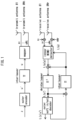
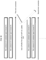
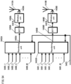
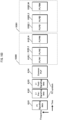
- Fig. 28 shows an example of the structure of a transmission and reception device when the number of transmit antennas is two, the number of receive antennas is two, and the number of modulated signals for transmission (transmission streams) is two.
- encoded data is interleaved, the interleaved data is modulated, and frequency conversion and the like is performed to generate transmission signals, and the transmission signals are transmitted from antennas.
- the scheme for simultaneously transmitting different modulated signals from different transmit antennas at the same time and at the same frequency is a spatial multiplexing MIMO system.
- Patent Literature 1 it has been suggested in Patent Literature 1 to use a transmission device provided with a different interleave pattern for each transmit antenna.
- the transmission device in Fig. 28 would have two different interleave patterns with respective interleaves ( ⁇ a, ⁇ b).
- reception quality is improved in the reception device by iterative performance of a detection scheme that uses soft values (the MIMO detector in Fig. 28 ).
- Models of actual propagation environments in wireless communications include non-line of sight (NLOS), of which a Rayleigh fading environment is representative, and line of sight (LOS), of which a Rician fading environment is representative.
- NLOS non-line of sight
- LOS line of sight
- the transmission device transmits a single modulated signal
- the reception device performs maximal ratio combining on the signals received by a plurality of antennas and then demodulates and decodes the signal resulting from maximal ratio combining
- excellent reception quality can be achieved in an LOS environment, in particular in an environment where the Rician factor is large, which indicates the ratio of the received power of direct waves versus the received power of scattered waves.
- the transmission system for example, spatial multiplexing MIMO system
- a problem occurs in that the reception quality deteriorates as the Rician factor increases (see Non-Patent Literature 3).
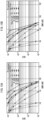
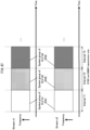
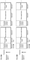
- Fig. 29A shows the BER characteristics of Max-log A Posteriori Probability (APP) without iterative detection (see Non-Patent Literature 1 and Non-Patent Literature 2), and Fig.
- APP Max-log A Posteriori Probability
- FIG. 29B shows the BER characteristics of Max-log-APP with iterative detection (see Non-Patent Literature 1 and Non-Patent Literature 2) (number of iterations: five).
- reception quality degrades in the spatial multiplexing MIMO system as the Rician factor increases. It is thus clear that the unique problem of "degradation of reception quality upon stabilization of the propagation environment in the spatial multiplexing MIMO system", which does not exist in a conventional single modulation signal transmission system, occurs in the spatial multiplexing MIMO system.
- Broadcast or multicast communication is a service directed towards line-of-sight users.
- the radio wave propagation environment between the broadcasting station and the reception devices belonging to the users is often an LOS environment.
- a spatial multiplexing MIMO system having the above problem for broadcast or multicast communication a situation may occur in which the received electric field strength is high at the reception device, but degradation in reception quality makes it impossible to receive the service.
- Non-Patent Literature 8 describes a scheme to select a codebook used in precoding (i.e. a precoding matrix, also referred to as a precoding weight matrix) based on feedback information from a communication partner.
- a precoding matrix also referred to as a precoding weight matrix
- Non-Patent Literature 8 does not at all disclose, however, a scheme for preceding in an environment in which feedback information cannot be acquired from the communication partner, such as in the above broadcast or multicast communication.
- Non-Patent Literature 4 discloses a scheme for hopping the precoding matrix over time. This scheme can be applied even when no feedback information is available.
- Non-Patent Literature 4 discloses using a unitary matrix as the matrix for preceding and hopping the unitary matrix at random but does not at all disclose a scheme applicable to degradation of reception quality in the above-described LOS environment.
- Non-Patent Literature 4 simply recites hopping between precoding matrices at random.
- Non-Patent Literature 4 makes no mention whatsoever of a precoding scheme, or a structure of a precoding matrix, for remedying degradation of reception quality in an LOS environment.
- Patent Literature 1 WO 2005/050885
- the present invention provides a precoding method for generating, from a plurality of signals which are based on a selected modulation scheme and represented by in-phase components and quadrature components, a plurality of precoded signals that are transmitted in the same frequency band at the same time and transmitting the generated precoded signals, the precoding method comprising: selecting one precoding weight matrix from among a plurality of precoding weight matrices by regularly hopping between the matrices; and generating the plurality of precoded signals by multiplying the selected precoding weight matrix by the plurality of signals which are based on the selected modulation scheme, the plurality of precoding weight matrices being nine matrices expressed, using a positive real number ⁇ , as Equations 339 through 347 (details are described below).
- precoded signals which are generated by precoding signals by using one precoding weight matrix selected from among a plurality of precoding weight matrices by regularly hopping between the matrices, are transmitted and received.
- the precoding weight matrix used in the precoding is any of a plurality of precoding weight matrices that have been predetermined. This makes it possible to improve the reception quality in an LOS environment based on the design of the plurality of precoding weight matrices.
- the present invention provides a precoding method, a precoding device, a transmission method, a reception method, a transmission device, and a reception device that remedy degradation of reception quality in an LOS environment, thereby providing high-quality service to LOS users during broadcast or multicast communication.
- the following describes the transmission scheme, transmission device, reception scheme, and reception device of the present embodiment.
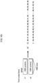
- Fig. 1 shows the structure of an N t ⁇ N r spatial multiplexing MIMO system.
- An information vector z is encoded and interleaved.
- u i (u i1 , ..., u iM ) (where M is the number of transmission bits per symbol).
- the normalized transmission energy is represented as E ⁇
- s i l 2 ⁇ Es/Nt (E s being the total energy per channel).
- the received vector is represented as in Equation 1.
- H NtNr is the channel matrix
- n i is the i.i.d. complex Gaussian random noise with an average value 0 and variance ⁇ 2 .
- the probability for the received vector may be provided as a multi-dimensional Gaussian distribution, as in Equation 2.
- a reception device that performs iterative decoding composed of an outer soft-in/soft-out decoder and a MIMO detector, as in Fig. 1 .
- the vector of a log-likelihood ratio (L-value) in Fig. 1 is represented as in Equations 3-5.
- Equation 6 can be expressed as Equation 7.
- Equation 7 L u mn
- y ln p y
- u mn + 1 p y
- Equation 8 L u mn
- Equation 12 the logarithmic probability of the equation defined in Equation 2 is represented in Equation 12.
- u ⁇ N r 2 ln 2 ⁇ 2 ⁇ 1 2 ⁇ 2 ⁇ y ⁇ Hs u ⁇ 2
- Equation 7 in MAP or A Posteriori Probability (APP), the a posteriori L-value is represented as follows.
- y ln ⁇ U mn , + 1 exp ⁇ 1 2 ⁇ 2 ⁇ y ⁇ Hs u ⁇ 2 + ⁇ ij lnP u ij ⁇ U mn , ⁇ 1 exp ⁇ 1 2 ⁇ 2 ⁇ y ⁇ Hs u ⁇ 2 + ⁇ ij lnP u ij
- Fig. 28 shows the basic structure of the system that is related to the subsequent description.
- This system is a 2 ⁇ 2 spatial multiplexing MIMO system.
- the two outer encoders are identical LDPC encoders.
- LDPC encoders As the outer encoders is described as an example, but the error correction coding used by the outer encoder is not limited to LDPC coding.
- the present invention may similarly be embodied using other error correction coding such as turbo coding, convolutional coding, LDPC convolutional coding, and the like.
- each outer encoder is described as having a transmit antenna, but the outer encoders are not limited to this structure.
- a plurality of transmit antennas may be used, and the number of outer encoders may be one. Also, a greater number of outer encoders may be used than the number of transmit antennas.)
- the streams A and B respectively have interleavers ( ⁇ a , ⁇ b ).
- the modulation scheme is 2 h -QAM (with h bits transmitted in one symbol).
- the reception device performs iterative detection on the above MIMO signals (iterative APP (or iterative Max-log APP) decoding).
- Decoding of LDPC codes is performed by, for example, sum-product decoding.
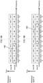
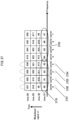
- Fig. 2 shows a frame structure and lists the order of symbols after interleaving.
- (i a , j a ), (i b , j b ) are represented by the following Equations.
- Math 16 i a j a ⁇ a ⁇ ia , ja a
- Math 17 i b j b ⁇ b ⁇ ib , jb a
- i a , i b indicate the order of symbols after interleaving
- ⁇ a , ⁇ b indicate the interleavers for the streams A and B
- ⁇ a ia,ja , ⁇ b ib,jb indicate the order of data in streams A and B before interleaving.
- A(m) represents the set of column indices of 1's in the m th column of the check matrix H
- B(n) represents the set of row indices of 1's in the n th row of the check matrix H.
- f represents a Gallager function. Furthermore, the scheme of seeking ⁇ n is described in detail later.
- the variables in stream A are m a , n a , ⁇ a mana , ⁇ a mana, ⁇ na , and L na
- the variables in stream B are m b ,n b , ⁇ b mbnb , ⁇ b mbnb , ⁇ nb , and L nb .
- Equations are defined from the frame structures of Fig. 2 and from Equations 16 and 17.
- Math 26 n a ⁇ ia , ja a
- Math 27 n b ⁇ ib , jb b
- n a ,n b ⁇ [1, N].
- ⁇ na , L na , ⁇ nb , and L nb where the number of iterations of iterative MIMO signal detection is k, are represented as ⁇ k,na , L k,na , ⁇ k,nb , and L k,nb .
- Step B ⁇ 2 (iterative detection; the number of iterations k): ⁇ k,na and ⁇ k,nb , where the number of iterations is k, are represented as in Equations 31-34, from Equations 11, 13-15, 16, and 17.
- Equations 31-34 from Equations 11, 13-15, 16, and 17.
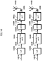
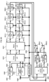
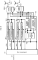
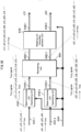
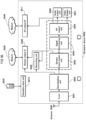
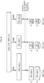
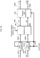
- Fig. 3 is an example of the structure of a transmission device 300 in the present embodiment.
- An encoder 302A receives information (data) 301A and a frame structure signal 313 as inputs and, in accordance with the frame structure signal 313, performs error correction coding such as convolutional coding, LDPC coding, turbo coding, or the like, outputting encoded data 303A.
- the frame structure signal 313 includes information such as the error correction scheme used for error correction coding of data, the coding rate, the block length, and the like.
- the encoder 302A uses the error correction scheme indicated by the frame structure signal 313. Furthermore, the error correction scheme may be hopped.
- An interleaver 304A receives the encoded data 303A and the frame structure signal 313 as inputs and performs interleaving, i.e. changing the order of the data, to output interleaved data 305A. (The scheme of interleaving may be hopped based on the frame structure signal 313.)
- a mapping unit 306A receives the interleaved data 305A and the frame structure signal 313 as inputs, performs modulation such as Quadrature Phase Shift Keying (QPSK), 16 Quadrature Amplitude Modulation (16QAM), 64 Quadrature Amplitude Modulation (64QAM), or the like, and outputs a resulting baseband signal 307A.
- modulation such as Quadrature Phase Shift Keying (QPSK), 16 Quadrature Amplitude Modulation (16QAM), 64 Quadrature Amplitude Modulation (64QAM), or the like.
- QPSK Quadrature Phase Shift Keying
- 16QAM 16 Quadrature Amplitude Modulation
- 64QAM 64 Quadrature Amplitude Modulation
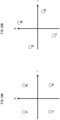
- Fig. 24B is an example of a different scheme of mapping in an I-Q plane for QPSK modulation than Fig. 24A . The difference between Fig. 24B and Fig. 24A is that the signal points in Fig.
- Non-Patent Literature 9 and Non-Patent Literature 10 describe such a constellation rotation scheme, and the Cyclic Q Delay described in Non-Patent Literature 9 and Non-Patent Literature 10 may also be adopted.
- Figs. 25A and 25B show signal point layout in the I-Q plane for 16QAM. The example corresponding to Fig. 24A is shown in Fig. 25A , and the example corresponding to Fig. 24B is shown in Fig. 25B .
- An encoder 302B receives information (data) 301B and the frame structure signal 313 as inputs and, in accordance with the frame structure signal 313, performs error correction coding such as convolutional coding, LDPC coding, turbo coding, or the like, outputting encoded data 303B.
- the frame structure signal 313 includes information such as the error correction scheme used, the coding rate, the block length, and the like.
- the error correction scheme indicated by the frame structure signal 313 is used. Furthermore, the error correction scheme may be hopped.
- An interleaver 304B receives the encoded data 303B and the frame structure signal 313 as inputs and performs interleaving, i.e. changing the order of the data, to output interleaved data 305B. (The scheme of interleaving may be hopped based on the frame structure signal 313.)
- a mapping unit 306B receives the interleaved data 305B and the frame structure signal 313 as inputs, performs modulation such as Quadrature Phase Shift Keying (QPSK), 16 Quadrature Amplitude Modulation (16QAM), 64 Quadrature Amplitude Modulation (64QAM), or the like, and outputs a resulting baseband signal 307B.
- modulation such as Quadrature Phase Shift Keying (QPSK), 16 Quadrature Amplitude Modulation (16QAM), 64 Quadrature Amplitude Modulation (64QAM), or the like.
- QPSK Quadrature Phase Shift Keying
- 16QAM 16 Quadrature Amplitude Modulation
- 64QAM 64 Quadrature Amplitude Modulation
- a weighting information generating unit 314 receives the frame structure signal 313 as an input and outputs information 315 regarding a weighting scheme based on the frame structure signal 313.
- the weighting scheme is characterized by regular hopping between weights.
- a weighting unit 308A receives the baseband signal 307A, the baseband signal 307B, and the information 315 regarding the weighting scheme, and based on the information 315 regarding the weighting scheme, performs weighting on the baseband signal 307A and the baseband signal 307B and outputs a signal 309A resulting from the weighting. Details on the weighting scheme are provided later.
- a wireless unit 310A receives the signal 309A resulting from the weighting as an input and performs processing such as orthogonal modulation, band limiting, frequency conversion, amplification, and the like, outputting a transmission signal 311A.
- a transmission signal 511A is output as a radio wave from an antenna 312A.
- a weighting unit 308B receives the baseband signal 307A, the baseband signal 307B, and the information 315 regarding the weighting scheme, and based on the information 315 regarding the weighting scheme, performs weighting on the baseband signal 307A and the baseband signal 307B and outputs a signal 309B resulting from the weighting.
- Fig. 26 shows the structure of a weighting unit.
- the baseband signal 307A is multiplied by w11(t), yielding w11(t)s1(t), and is multiplied by w21(t), yielding w21(t)s1(t).
- the baseband signal 307B is multiplied by w12(t) to generate w12(t)s2(t) and is multiplied by w22(t) to generate w22(t)s2(t).
- a wireless unit 310B receives the signal 309B resulting from the weighting as an input and performs processing such as orthogonal modulation, band limiting, frequency conversion, amplification, and the like, outputting a transmission signal 311B.
- the transmission signal 311B is output as a radio wave from an antenna 312B.
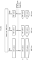
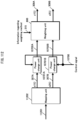
- Fig. 4 shows an example of the structure of a transmission device 400 that differs from Fig. 3 . The differences in Fig. 4 from Fig. 3 are described.
- An encoder 402 receives information (data) 401 and the frame structure signal 313 as inputs and, in accordance with the frame structure signal 313, performs error correction coding and outputs encoded data 403.
- a distribution unit 404 receives the encoded data 403 as an input, distributes the data 403, and outputs data 405A and data 405B. Note that in Fig. 4 , one encoder is shown, but the number of encoders is not limited in this way. The present invention may similarly be embodied when the number of encoders is m (where m is an integer greater than or equal to one) and the distribution unit divides encoded data generated by each encoder into two parts and outputs the divided data.
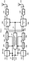
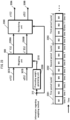
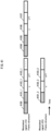
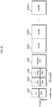
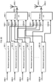
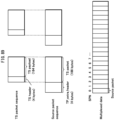
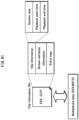
- Fig. 5 shows an example of a frame structure in the time domain for a transmission device according to the present embodiment.
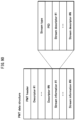
- a symbol 500_1 is a symbol for notifying the reception device of the transmission scheme.
- the symbol 500_1 conveys information such as the error correction scheme used for transmitting data symbols, the coding rate, and the modulation scheme used for transmitting data symbols.
- the symbol 501_1 is for estimating channel fluctuation for the modulated signal z1(t) (where t is time) transmitted by the transmission device.
- the symbol 502_1 is the data symbol transmitted as symbol number u (in the time domain) by the modulated signal z1(t)
- the symbol 503_1 is the data symbol transmitted as symbol number u + 1 by the modulated signal z1(t).
- the symbol 501_2 is for estimating channel fluctuation for the modulated signal z2(t) (where t is time) transmitted by the transmission device.
- the symbol 502_2 is the data symbol transmitted as symbol number u by the modulated signal z2(t)
- the symbol 503_2 is the data symbol transmitted as symbol number u + 1 by the modulated signal z2(t).
- the following describes the relationships between the modulated signals z1(t) and z2(t) transmitted by the transmission device and the received signals r1(t) and r2(t) received by the reception device.
- 504#1 and 504#2 indicate transmit antennas in the transmission device
- 505#1 and 505#2 indicate receive antennas in the reception device.
- the transmission device transmits the modulated signal z1(t) from transmit antenna 504#1 and transmits the modulated signal z2(t) from transmit antenna 504#2.
- the modulated signal z1(t) and the modulated signal z2(t) are assumed to occupy the same (a shared/common) frequency (band).
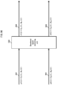
- Fig. 6 relates to the weighting scheme (precoding scheme) in the present embodiment.
- a weighting unit 600 integrates the weighting units 308A and 308B in Fig. 3 .
- a stream s1(t) and a stream s2(t) correspond to the baseband signals 307A and 307B in Fig. 3 .
- the streams s1(t) and s2(t) are the baseband signal in-phase components I and quadrature components Q when mapped according to a modulation scheme such as QPSK, 16QAM, 64QAM, or the like.
- a modulation scheme such as QPSK, 16QAM, 64QAM, or the like.
- the stream s1(t) is represented as s1(u) at symbol number u, as s1(u + 1) at symbol number u + 1, and so forth.
- the stream s2(t) is represented as s2(u) at symbol number u, as s2(u + 1) at symbol number u + 1, and so forth.
- the weighting unit 600 receives the baseband signals 307A (s1(t)) and 307B (s2(t)) and the information 315 regarding weighting information in Fig.
- z1(t) and z2(t) are represented as follows.
- symbol number 4i (where i is an integer greater than or equal to zero):
- j is an imaginary unit.
- the weighting unit in Fig. 6 regularly hops between precoding weights over a four-slot period (cycle). (although precoding weights have been described as being hopped between regularly over four slots, the number of slots for regular hopping is not limited to four.)
- Non-Patent Literature 4 describes hopping the precoding weights for each slot. This hopping of precoding weights is characterized by being random. On the other hand, in the present embodiment, a certain period (cycle) is provided, and the precoding weights are hopped between regularly. Furthermore, in each 2 ⁇ 2 precoding weight matrix composed of four precoding weights, the absolute value of each of the four precoding weights is equivalent to (1/sqrt(2)), and hopping is regularly performed between precoding weight matrices having this characteristic.
- reception quality may greatly improve, yet the special precoding matrix differs depending on the conditions of direct waves.
- a certain tendency exists, and if precoding matrices are hopped between regularly in accordance with this tendency, the reception quality of data greatly improves.
- a precoding matrix other than the above-described special preceding matrix may exist, and the possibility of performing precoding only with biased precoding matrices that are not suitable for the LOS environment also exists. Therefore, in an LOS environment, excellent reception quality may not always be obtained. Accordingly, there is a need for a precoding hopping scheme suitable for an LOS environment.
- the present invention proposes such a precoding scheme.
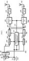
- Fig. 7 is an example of the structure of a reception device 700 in the present embodiment.
- a wireless unit 703_X receives, as an input, a received signal 702_X received by an antenna 701_X, performs processing such as frequency conversion, quadrature demodulation, and the like, and outputs a baseband signal 704_X.
- a channel fluctuation estimating unit 705_1 for the modulated signal z1 transmitted by the transmission device receives the baseband signal 704_X as an input, extracts a reference symbol 501_1 for channel estimation as in Fig. 5 , estimates a value corresponding to h 11 in Equation 36, and outputs a channel estimation signal 706_1.
- a channel fluctuation estimating unit 705_2 for the modulated signal z2 transmitted by the transmission device receives the baseband signal 704_X as an input, extracts a reference symbol 501_2 for channel estimation as in Fig. 5 , estimates a value corresponding to h 12 in Equation 36, and outputs a channel estimation signal 706_2.
- a wireless unit 703_Y receives, as input, a received signal 702_Y received by an antenna 701_Y, performs processing such as frequency conversion, quadrature demodulation, and the like, and outputs a baseband signal 704_Y.
- a channel fluctuation estimating unit 707_1 for the modulated signal z1 transmitted by the transmission device receives the baseband signal 704_Y as an input, extracts a reference symbol 501_1 for channel estimation as in Fig. 5 , estimates a value corresponding to h 21 in Equation 36, and outputs a channel estimation signal 708_1.
- a channel fluctuation estimating unit 707_2 for the modulated signal z2 transmitted by the transmission device receives the baseband signal 704_Y as an input, extracts a reference symbol 501_2 for channel estimation as in Fig. 5 , estimates a value corresponding to h 22 in Equation 36, and outputs a channel estimation signal 708_2.
- a control information decoding unit 709 receives the baseband signal 704_X and the baseband signal 704_Y as inputs, detects the symbol 500_1 that indicates the transmission scheme as in Fig. 5 , and outputs a signal 710 regarding information on the transmission scheme indicated by the transmission device.
- a signal processing unit 711 receives, as inputs, the baseband signals 704_X and 704_Y, the channel estimation signals 706_1, 706_2, 708_1, and 708_2, and the signal 710 regarding information on the transmission scheme indicated by the transmission device, performs detection and decoding, and outputs received data 712_1 and 712_2.
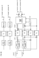
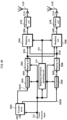
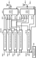
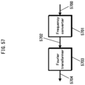
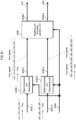
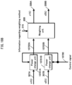
- Fig. 8 is an example of the structure of the signal processing unit 711 in the present embodiment.
- Fig. 8 shows an INNER MIMO detector, a soft-in/soft-out decoder, and a weighting coefficient generating unit as the main elements.
- Non-Patent Literature 2 and Non-Patent Literature 3 describe the scheme of iterative decoding with this structure.
- the MIMO system described in Non-Patent Literature 2 and Non-Patent Literature 3 is a spatial multiplexing MIMO system, whereas the present embodiment differs from Non-Patent Literature 2 and Non-Patent Literature 3 by describing a MIMO system that changes precoding weights with time.
- R t H t W t S t
- the reception device can apply the decoding scheme in Non-Patent Literature 2 and Non-Patent Literature 3 to the received vector R(t) by considering H(t)W(t) as the channel matrix.
- a weighting coefficient generating unit 819 in Fig. 8 receives, as input, a signal 818 regarding information on the transmission scheme indicated by the transmission device (corresponding to 710 in Fig. 7 ) and outputs a signal 820 regarding information on weighting coefficients.
- An INNER MIMO detector 803 receives the signal 820 regarding information on weighting coefficients as input and, using the signal 820, performs the calculation in Equation 41. Iterative detection and decoding is thus performed. The following describes operations thereof.
- a processing scheme such as that shown in Fig. 10 is necessary for iterative decoding (iterative detection).
- one codeword (or one frame) of the modulated signal (stream) s1 and one codeword (or one frame) of the modulated signal (stream) s2 are decoded.
- the Log-Likelihood Ratio (LLR) of each bit of the one codeword (or one frame) of the modulated signal (stream) s1 and of the one codeword (or one frame) of the modulated signal (stream) s2 is obtained from the soft-in/soft-out decoder. Detection and decoding is performed again using the LLR.
- a storage unit 815 receives, as inputs, a baseband signal 801X (corresponding to the baseband signal 704_X in Fig. 7 ), a channel estimation signal group 802X (corresponding to the channel estimation signals 706_1 and 706_2 in Fig. 7 ), a baseband signal 801Y (corresponding to the baseband signal 704_Y in Fig. 7 ), and a channel estimation signal group 802Y (corresponding to the channel estimation signals 708_1 and 708_2 in Fig. 7 ).
- the storage unit 815 calculates H(t)W(t) in Equation 41 and stores the calculated matrix as a transformed channel signal group.
- the storage unit 815 outputs the above signals when necessary as a baseband signal 816X, a transformed channel estimation signal group 817X, a baseband signal 816Y, and a transformed channel estimation signal group 817Y.
- the INNER MIMO detector 803 receives, as inputs, the baseband signal 801X, the channel estimation signal group 802X, the baseband signal 801Y, and the channel estimation signal group 802Y.
- the modulation scheme for the modulated signal (stream) s1 and the modulated signal (stream) s2 is described as 16QAM.
- the INNER MIMO detector 803 first calculates H(t)W(t) from the channel estimation signal group 802X and the channel estimation signal group 802Y to seek candidate signal points corresponding to the baseband signal 801X.
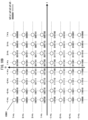
- Fig. 11 shows such calculation.
- each black dot ( ⁇ ) is a candidate signal point in the I-Q plane. Since the modulation scheme is 16QAM, there are 256 candidate signal points. (Since Fig.
- E X (b0, b1, b2, b3, b4, b5, b6, b7), i.e. the value of the squared Euclidian distance between a candidate signal point corresponding to (b0, b1, b2, b3, b4, b5, b6, b7) and a received signal point, divided by the noise variance, is sought.
- the baseband signals and the modulated signals s1 and s2 are each complex signals.
- H(t)W(t) is calculated from the channel estimation signal group 802X and the channel estimation signal group 802Y, candidate signal points corresponding to the baseband signal 801Y are sought, the squared Euclidian distance for the received signal point (corresponding to the baseband signal 801Y) is sought, and the squared Euclidian distance is divided by the noise variance ⁇ 2 .
- E Y (b0, b1, b2, b3, b4, b5, b6, b7), i.e. the value of the squared Euclidian distance between a candidate signal point corresponding to (b0, b1, b2, b3, b4, b5, b6, b7) and a received signal point, divided by the noise variance, is sought.
- E X (b0, b1, b2, b3, b4, b5, b6, b7) + E Y (b0, b1, b2, b3, b4, b5, b6, b7) E(b0, b1, b2, b3, b4, b5, b6, b7) is sought.
- the INNER MIMO detector 803 outputs E(b0, b1, b2, b3, b4, b5, b6, b7) as a signal 804.
- a log-likelihood calculating unit 805A receives the signal 804 as input, calculates the log likelihood for bits b0, b1, b2, and b3, and outputs a log-likelihood signal 806A. Note that during calculation of the log likelihood, the log likelihood for "1" and the log likelihood for "0" are calculated. The calculation scheme is as shown in Equations 28, 29, and 30. Details can be found in Non-Patent Literature 2 and Non-Patent Literature 3.
- a log-likelihood calculating unit 805B receives the signal 804 as input, calculates the log likelihood for bits b4, b5, b6, and b7, and outputs a log-likelihood signal 806B.
- a deinterleaver (807A) receives the log-likelihood signal 806A as an input, performs deinterleaving corresponding to the interleaver (the interleaver (304A) in Fig. 3 ), and outputs a deinterleaved log-likelihood signal 808A.
- a deinterleaver (807B) receives the log-likelihood signal 806B as an input, performs deinterleaving corresponding to the interleaver (the interleaver (304B) in Fig. 3 ), and outputs a deinterleaved log-likelihood signal 808B.
- a log-likelihood ratio calculating unit 809A receives the interleaved log-likelihood signal 808A as an input, calculates the log-likelihood ratio (LLR) of the bits encoded by the encoder 302A in Fig. 3 , and outputs a log-likelihood ratio signal 810A.
- LLR log-likelihood ratio
- a log-likelihood ratio calculating unit 809B receives the interleaved log-likelihood signal 808B as an input, calculates the log-likelihood ratio (LLR) of the bits encoded by the encoder 302B in Fig. 3 , and outputs a log-likelihood ratio signal 810B.
- LLR log-likelihood ratio
- a soft-in/soft-out decoder 811A receives the log-likelihood ratio signal 810A as an input, performs decoding, and outputs a decoded log-likelihood ratio 812A.
- a soft-in/soft-out decoder 811B receives the log-likelihood ratio signal 810B as an input, performs decoding, and outputs a decoded log-likelihood ratio 812B.
- An interleaver (813A) receives the log-likelihood ratio 812A decoded by the soft-in/soft-out decoder in the (k - 1) th iteration as an input, performs interleaving, and outputs an interleaved log-likelihood ratio 814A.
- the interleaving pattern in the interleaver (813A) is similar to the interleaving pattern in the interleaver (304A) in Fig. 3 .
- An interleaver (813B) receives the log-likelihood ratio 812B decoded by the soft-in/soft-out decoder in the (k - 1) th iteration as an input, performs interleaving, and outputs an interleaved log-likelihood ratio 814B.
- the interleaving pattern in the interleaver (813B) is similar to the interleaving pattern in the interleaver (304B) in Fig. 3 .
- the INNER MIMO detector 803 receives, as inputs, the baseband signal 816X, the transformed channel estimation signal group 817X, the baseband signal 816Y, the transformed channel estimation signal group 817Y, the interleaved log-likelihood ratio 814A, and the interleaved log-likelihood ratio 814B.
- the reason for using the baseband signal 816X, the transformed channel estimation signal group 817X, the baseband signal 816Y, and the transformed channel estimation signal group 817Y instead of the baseband signal 801X, the channel estimation signal group 802X, the baseband signal 801Y, and the channel estimation signal group 802Y is because a delay occurs due to iterative decoding.
- the difference between operations by the INNER MIMO detector 803 for iterative decoding and for initial detection is the use of the interleaved log-likelihood ratio 814A and the interleaved log-likelihood ratio 814B during signal processing.
- the INNER MIMO detector 803 first seeks E(b0, b1, b2, b3, b4, b5, b6, b7), as during initial detection. Additionally, coefficients corresponding to Equations 11 and 32 are sought from the interleaved log-likelihood ratio 814A and the interleaved log-likelihood ratio 914B.
- the value E(b0, b1, b2, b3, b4, b5, b6, b7) is adjusted using the sought coefficients, and the resulting value E'(b0, b1, b2, b3, b4, b5, b6, b7) is output as the signal 804.
- the log-likelihood calculating unit 805A receives the signal 804 as input, calculates the log likelihood for bits b0, b1, b2, and b3, and outputs the log-likelihood signal 806A. Note that during calculation of the log likelihood, the log likelihood for "1" and the log likelihood for "0" are calculated.
- the calculation scheme is as shown in Equations 31, 32, 33, 34, and 35. Details can be found in Non-Patent Literature 2 and Non-Patent Literature 3.
- the log-likelihood calculating unit 805B receives the signal 804 as input, calculates the log likelihood for bits b4, b5, b6, and b7, and outputs the log-likelihood signal 806B. Operations by the deinterleaver onwards are similar to initial detection.
- FIG. 8 shows the structure of the signal processing unit when performing iterative detection
- iterative detection is not always essential for obtaining excellent reception quality, and a structure not including the interleavers 813A and 813B, which are necessary only for iterative detection, is possible.
- the INNER MIMO detector 803 does not perform iterative detection.
- the main part of the present embodiment is calculation of H(t)W(t). Note that as shown in Non-Patent Literature 5 and the like, QR decomposition may be used to perform initial detection and iterative detection.
- Non-Patent Literature 11 based on H(t)W(t), linear operation of the Minimum Mean Squared Error (MMSE) and Zero Forcing (ZF) may be performed in order to perform initial detection.
- MMSE Minimum Mean Squared Error
- ZF Zero Forcing
- Fig. 9 is the structure of a different signal processing unit than Fig. 8 and is for the modulated signal transmitted by the transmission device in Fig. 4 .
- the difference with Fig. 8 is the number of soft-in/soft-out decoders.
- a soft-in/soft-out decoder 901 receives, as inputs, the log-likelihood ratio signals 810A and 810B, performs decoding, and outputs a decoded log-likelihood ratio 902.
- a distribution unit 903 receives the decoded log-likelihood ratio 902 as an input and distributes the log-likelihood ratio 902. Other operations are similar to Fig. 8 .
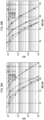
- Figs. 12A and 12B show BER characteristics for a transmission scheme using the precoding weights of the present embodiment under similar conditions to Figs. 29A and 29B .
- Fig. 12A shows the BER characteristics of Max-log A Posteriori Probability (APP) without iterative detection (see Non-Patent Literature 1 and Non-Patent Literature 2)
- Fig. 12B shows the BER characteristics of Max-log-APP with iterative detection (see Non-Patent Literature 1 and Non-Patent Literature 2) (number of iterations: five). Comparing Figs.
- APP Posteriori Probability
- 12A, 12B , 29A, and 29B shows how if the transmission scheme of the present embodiment is used, the BER characteristics when the Rician factor is large greatly improve over the BER characteristics when using spatial multiplexing MIMO system, thereby confirming the usefulness of the scheme in the present embodiment.
- the advantageous effect of improved transmission quality is achieved in an LOS environment in which direct waves dominate by hopping between precoding weights regularly over time, as in the present embodiment.
- the present invention may be embodied in the same way even if the number of antennas increases. In other words, the number of antennas in the reception device does not affect the operations or advantageous effects of the present embodiment.
- the example of LDPC coding has particularly been explained, but the present invention is not limited to LDPC coding.
- the soft-in/soft-out decoders are not limited to the example of sum-product decoding. Another soft-in/soft-out decoding scheme may be used, such as a BCJR algorithm, a SOVA algorithm, a Max-log-MAP algorithm, and the like. Details are provided in Non-Patent Literature 6.
- the present invention is not limited in this way and may be similarly embodied for multi-carrier transmission. Accordingly, when using a scheme such as spread spectrum communication, Orthogonal Frequency-Division Multiplexing (OFDM), Single Carrier Frequency Division Multiple Access (SC-FDMA), Single Carrier Orthogonal Frequency-Division Multiplexing (SC-OFDM), or wavelet OFDM as described in Non-Patent Literature 7 and the like, for example, the present invention may be similarly embodied. Furthermore, in the present embodiment, symbols other than data symbols, such as pilot symbols (preamble, unique word, and the like), symbols for transmission of control information, and the like, may be arranged in the frame in any way.
- OFDM Orthogonal Frequency-Division Multiplexing
- SC-FDMA Single Carrier Frequency Division Multiple Access
- SC-OFDM Single Carrier Orthogonal Frequency-Division Multiplexing
- symbols other than data symbols such as pilot symbols (preamble, unique word, and the like
- the following describes an example of using OFDM as an example of a multi-carrier scheme.
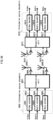
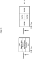
- Fig. 13 shows the structure of a transmission device when using OFDM.
- elements that operate in a similar way to Fig. 3 bear the same reference signs.
- An OFDM related processor 1301A receives, as input, the weighted signal 309A, performs processing related to OFDM, and outputs a transmission signal 1302A.
- an OFDM related processor 1301B receives, as input, the weighted signal 309B, performs processing related to OFDM, and outputs a transmission signal 1302B.
- Fig. 14 shows an example of a structure from the OFDM related processors 1301A and 1301B in Fig. 13 onwards.
- the part from 1401A to 1410A is related to the part from 1301A to 312A in Fig. 13
- the part from 1401B to 1410B is related to the part from 1301B to 312B in Fig. 13 .
- a serial/parallel converter 1402A performs serial/parallel conversion on a weighted signal 1401A (corresponding to the weighted signal 309A in Fig. 13 ) and outputs a parallel signal 1403A.
- a reordering unit 1404A receives a parallel signal 1403A as input, performs reordering, and outputs a reordered signal 1405A. Reordering is described in detail later.
- An inverse fast Fourier transformer 1406A receives the reordered signal 1405A as an input, performs a fast Fourier transform, and outputs a fast Fourier transformed signal 1407A.
- a wireless unit 1408A receives the fast Fourier transformed signal 1407A as an input, performs processing such as frequency conversion, amplification, and the like, and outputs a modulated signal 1409A.
- the modulated signal 1409A is output as a radio wave from an antenna 1410A.
- a serial/parallel converter 1402B performs serial/parallel conversion on a weighted signal 1401B (corresponding to the weighted signal 309B in Fig. 13 ) and outputs a parallel signal 1403B.
- a reordering unit 1404B receives a parallel signal 1403B as input, performs reordering, and outputs a reordered signal 1405B. Reordering is described in detail later.
- An inverse fast Fourier transformer 1406B receives the reordered signal 1405B as an input, performs a fast Fourier transform, and outputs a fast Fourier transformed signal 1407B.
- a wireless unit 1408B receives the fast Fourier transformed signal 1407B as an input, performs processing such as frequency conversion, amplification, and the like, and outputs a modulated signal 1409B.
- the modulated signal 1409B is output as a radio wave from an antenna 1410B.
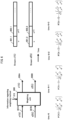
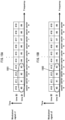
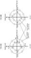
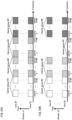
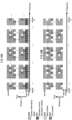
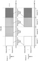
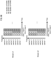
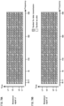
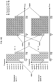
- Figs. 15A and 15B show an example of a scheme of reordering symbols by reordering units 1401A and 1401B in Fig. 14 , the horizontal axis representing frequency, and the vertical axis representing time.
- the frequency domain runs from (sub)carrier 0 through (sub)carrier 9.
- the modulated signals z1 and z2 use the same frequency band at the same time.
- Fig. 15A shows the reordering scheme for symbols of the modulated signal z1
- Fig. 15B shows the reordering scheme for symbols of the modulated signal z2. Numbers #1, #2, #3, #4, ... are assigned to in order to the symbols of the weighted signal 1401A which is input into the serial/parallel converter 1402A.
- the symbols #1, #2, #3, #4, ... are arranged in order starting from carrier 0.
- the symbols #1 through #9 are assigned to time $1, and subsequently, the symbols #10 through #19 are assigned to time $2.
- numbers #1, #2, #3, #4, ... are assigned in order to the symbols of the weighted signal 1401B which is input into the serial/parallel converter 1402B.
- symbols are assigned regularly, as shown in Fig. 15B .
- the symbols #1, #2, #3, #4, ... are arranged in order starting from carrier 0.
- the symbols #1 through #9 are assigned to time $1, and subsequently, the symbols #10 through #19 are assigned to time $2.
- the modulated signals z1 and z2 are complex signals.
- the symbol group 1501 and the symbol group 1502 shown in Figs. 15A and 15B are the symbols for one period (cycle) when using the precoding weight hopping scheme shown in Fig. 6 .
- Symbol #0 is the symbol when using the precoding weight of slot 4i in Fig. 6 .
- Symbol #1 is the symbol when using the precoding weight of slot 4i + 1 in Fig. 6 .
- Symbol #2 is the symbol when using the precoding weight of slot 4i + 2 in Fig. 6 .
- Symbol #3 is the symbol when using the precoding weight of slot 4i + 3 in Fig. 6 .
- symbol #x is as follows. When x mod 4 is 0, the symbol #x is the symbol when using the precoding weight of slot 4i in Fig. 6 .
- the symbol #x is the symbol when using the precoding weight of slot 4i + 1 in Fig. 6 .
- the symbol #x is the symbol when using the precoding weight of slot 4i + 2 in Fig. 6 .
- the symbol #x is the symbol when using the preceding weight of slot 4i + 3 in Fig. 6 .
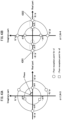
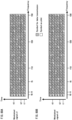
- Figs. 16A and 16B show an example of a scheme of reordering symbols by the reordering units 1404A and 1404B in Fig. 14 , the horizontal axis representing frequency, and the vertical axis representing time, that differs from Figs. 15A and 15B .
- Fig. 16A shows the reordering scheme for symbols of the modulated signal z1
- Fig. 16B shows the reordering scheme for symbols of the modulated signal z2.
- the difference in Figs. 16A and 16B as compared to Figs. 15A and 15B is that the reordering scheme of the symbols of the modulated signal z1 differs from the reordering scheme of the symbols of the modulated signal z2.
- Fig. 16A and 16B shows an example of a scheme of reordering symbols by the reordering units 1404A and 1404B in Fig. 14 , the horizontal axis representing frequency, and the vertical axis representing time, that differs from
- symbols #0 through #5 are assigned to carriers 4 through 9, and symbols #6 through #9 are assigned to carriers 0 through 3. Subsequently, symbols #10 through #19 are assigned regularly in the same way.
- the symbol group 1601 and the symbol group 1602 shown in Figs. 16A and 16B are the symbols for one period (cycle) when using the precoding weight hopping scheme shown in Fig. 6 .
- Figs. 17A and 17B show an example of a scheme of reordering symbols by the reordering units 1404A and 1404B in Fig. 14 , the horizontal axis representing frequency, and the vertical axis representing time, that differs from Figs. 15A and 15B .
- Fig. 17A shows the reordering scheme for symbols of the modulated signal z1
- Fig. 17B shows the reordering scheme for symbols of the modulated signal z2.
- the difference in Figs. 17A and 17B as compared to Figs. 15A and 15B is that whereas the symbols are arranged in order by carrier in Figs. 15A and 15B , the symbols are not arranged in order by carrier in Figs. 17A and 17B .
- the reordering scheme of the symbols of the modulated signal z1 may differ from the reordering scheme of the symbols of the modulated signal z2, as in Figs. 16A and 16B .
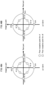
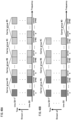
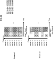
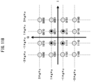
- Figs. 18A and 18B show an example of a scheme of reordering symbols by the reordering units 1404A and 1404B in Fig. 14 , the horizontal axis representing frequency, and the vertical axis representing time, that differs from Figs. 15A through 17B .
- Fig. 18A shows the reordering scheme for symbols of the modulated signal z1
- Fig. 18B shows the reordering scheme for symbols of the modulated signal z2.
- symbols are arranged in the frequency domain
- Figs. 18A and 18B symbols are arranged in both the frequency and time domains.
- Fig. 6 an example has been described of hopping between precoding weights over four slots. Here, however, an example of hopping over eight slots is described.
- the symbol groups 1801 and 1802 shown in Figs. 18A and 18B are the symbols for one period (cycle) when using the precoding weight hopping scheme (and are therefore eight-symbol groups).
- Symbol #0 is the symbol when using the precoding weight of slot 8i.
- Symbol #1 is the symbol when using the precoding weight of slot 8i + 1.
- Symbol #2 is the symbol when using the precoding weight of slot 8i + 2.
- Symbol #3 is the symbol when using the precoding weight of slot 8i + 3.
- Symbol #4 is the symbol when using the precoding weight of slot 8i + 4.
- symbol #5 is the symbol when using the precoding weight of slot 8i + 5.
- Symbol #6 is the symbol when using the precoding weight of slot 8i + 6.
- Symbol #7 is the symbol when using the precoding weight of slot 8i + 7. Accordingly, symbol #x is as follows. When x mod 8 is 0, the symbol #x is the symbol when using the precoding weight of slot 8i. When x mod 8 is 1, the symbol #x is the symbol when using the precoding weight of slot 8i + 1. When x mod 8 is 2, the symbol #x is the symbol when using the precoding weight of slot 8i + 2. When x mod 8 is 3, the symbol #x is the symbol when using the precoding weight of slot 8i + 3.
- Figs. 19A and 19B show an example of a scheme of reordering symbols by the reordering units 1404A and 1404B in Fig. 14 , the horizontal axis representing frequency, and the vertical axis representing time, that differs from Figs. 18A and 18B .
- Fig. 19A shows the reordering scheme for symbols of the modulated signal z1
- Fig. 19B shows the reordering scheme for symbols of the modulated signal z2.
- Figs. 19A and 19B show arrangement of symbols using both the frequency and the time axes. The difference as compared to Figs.
- the symbol group 1901 and the symbol group 1902 are the symbols for one period (cycle) when using the precoding hopping scheme.
- the present invention may be similarly embodied, and the advantageous effect of high reception quality achieved, with the symbol arranging scheme of the modulated signal z1 differing from the symbol arranging scheme of the modulated signal z2.
- the present invention may be similarly embodied, and the advantageous effect of high reception quality achieved, without arranging the symbols in order.
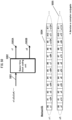
- Fig. 27 shows an example of a scheme of reordering symbols by the reordering units 1404A and 1404B in Fig. 14 , the horizontal axis representing frequency, and the vertical axis representing time, that differs from the above examples.
- symbol #0 is precoded using the precoding matrix in Equation 37
- symbol #1 is precoded using the preceding matrix in Equation 38
- symbol #2 is precoded using the precoding matrix in Equation 39
- symbol #3 is precoded using the precoding matrix in Equation 40.
- symbol #4 is precoded using the precoding matrix in Equation 37
- symbol #5 is precoded using the precoding matrix in Equation 38
- symbol #6 is precoded using the preceding matrix in Equation 39
- symbol #7 is precoded using the preceding matrix in Equation 40.
- symbol #0 is precoded using the precoding matrix in Equation 37
- symbol #9 is precoded using the precoding matrix in Equation 38
- symbol #18 is precoded using the precoding matrix in Equation 39
- symbol #27 is precoded using the precoding matrix in Equation 40.
- symbol #28 is precoded using the precoding matrix in Equation 37
- symbol #1 is precoded using the precoding matrix in Equation 38
- symbol #10 is precoded using the precoding matrix in Equation 39
- symbol #19 is precoded using the precoding matrix in Equation 40.
- symbol #20 is precoded using the precoding matrix in Equation 37
- symbol #29 is precoded using the precoding matrix in Equation 38
- symbol #2 is precoded using the precoding matrix in Equation 39
- symbol #11 is precoded using the precoding matrix in Equation 40.
- symbol #12 is precoded using the precoding matrix in Equation 37
- symbol #21 is precoded using the precoding matrix in Equation 38
- symbol #30 is precoded using the precoding matrix in Equation 39
- symbol #3 is precoded using the precoding matrix in Equation 40.
- Fig. 27 The characteristic of Fig. 27 is that, for example focusing on symbol #11, the symbols on either side in the frequency domain at the same time (symbols #10 and #12) are both precoded with a different precoding matrix than symbol #11, and the symbols on either side in the time domain in the same carrier (symbols #2 and #20) are both precoded with a different precoding matrix than symbol #11. This is true not only for symbol #11. Any symbol having symbols on either side in the frequency domain and the time domain is characterized in the same way as symbol #11. As a result, precoding matrices are effectively hopped between, and since the influence on stable conditions of direct waves is reduced, the possibility of improved reception quality of data increases.
- Fig. 27 when symbols are arranged in the frequency domain and time progresses in the time domain, the above characteristic is achieved by cyclically shifting the number of the arranged symbol, but the above characteristic may also be achieved by randomly (or regularly) arranging the symbols.
- Embodiment 1 regular hopping of the precoding weights as shown in Fig. 6 has been described.
- a scheme for designing specific precoding weights that differ from the precoding weights in Fig. 6 is described.
- j is an imaginary unit.
- Equations 46-49 can be represented as follows.
- Equations 46-49 can be represented as follows.
- design requirements for not only ⁇ 1 , and ⁇ 12 , but also for ⁇ and ⁇ are described. It suffices to set ⁇ to a certain value; it is then necessary to establish requirements for ⁇ .
- phase of these eight points should be evenly distributed (since the phase of a direct wave is considered to have a high probability of even distribution).
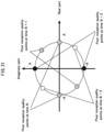
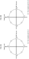
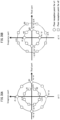
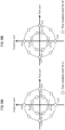
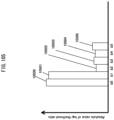
- the phase becomes even at the points at which reception quality is poor by setting ⁇ to ⁇ 3 ⁇ /4 radians. For example, letting ⁇ be 3 ⁇ /4 radians in example #1 (and letting A be a positive real number), then each of the four slots, points at which reception quality becomes poor exist once, as shown in Fig. 20 .
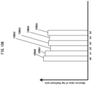
- the phase becomes even at the points at which reception quality is poor by setting ⁇ to ⁇ ⁇ radians. For example, letting ⁇ be ⁇ radians in example #3, then in each of the four slots, points at which reception quality becomes poor exist once, as shown in Fig. 21 . (If the element q in the channel matrix H exists at the points shown in Figs. 20 and 21 , reception quality degrades.)
- j is an imaginary unit.
- Math 65 z 1 Ni + 1 z 2 Ni + 1 1 2 e j ⁇ 11 Ni + 1 e j ⁇ 11 Ni + 1 + ⁇ e j ⁇ 21 Ni + 1 e j ⁇ 21 Ni + 1 + ⁇ + ⁇ s 1 Ni + 1 s 2 Ni + 1
- r1 and r2 are represented as follows.
- Ni (where i is an integer greater than or equal to zero):
- Math 68 r 1 Ni r 2 Ni 1 2 h 11 Ni h 12 Ni h 21 Ni h 22 Ni e j ⁇ 11 Ni e j ⁇ 11 Ni + ⁇ e j ⁇ 21 Ni e j ⁇ 21 Ni + ⁇ + ⁇ s 1 Ni s 2 Ni
- j is an imaginary unit.
- Equations 66-69 can be represented as follows.
- Ni (where i is an integer greater than or equal to zero):
- j is an imaginary unit.
- j is an imaginary unit.
- design requirements for not only ⁇ 11 and ⁇ 12 , but also for ⁇ and ⁇ are described. It suffices to set ⁇ to a certain value; it is then necessary to establish requirements for ⁇ .
- phase of these 2N points should be evenly distributed (since the phase of a direct wave at each reception device is considered to have a high probability of even distribution).
- the advantageous effect of improved transmission quality is achieved in an LOS environment in which direct waves dominate by hopping between precoding weights regularly over time.
- the structure of the reception device is as described in Embodiment 1, and in particular with regards to the structure of the reception device, operations have been described for a limited number of antennas, but the present invention may be embodied in the same way even if the number of antennas increases. In other words, the number of antennas in the reception device does not affect the operations or advantageous effects of the present embodiment. Furthermore, in the present embodiment, similar to Embodiment 1, the error correction codes are not limited.
- the present invention in contrast with Embodiment 1, the scheme of changing the precoding weights in the time domain has been described. As described in Embodiment 1, however, the present invention may be similarly embodied by changing the precoding weights by using a multi-carrier transmission scheme and arranging symbols in the frequency domain and the frequency-time domain. Furthermore, in the present embodiment, symbols other than data symbols, such as pilot symbols (preamble, unique word, and the like), symbols for control information, and the like, may be arranged in the frame in any way.
- pilot symbols preamble, unique word, and the like
- Embodiment 1 and Embodiment 2 the scheme of regularly hopping between precoding weights has been described for the case where the amplitude of each element in the precoding weight matrix is equivalent. In the present embodiment, however, an example that does not satisfy this condition is described.
- Ni + 1 1 + 1 e j ⁇ 11 Ni + 1 ⁇ ⁇ e j ⁇ 11 Ni + 1 + ⁇ ⁇ ⁇ e j ⁇ 21 Ni + 1 e j ⁇ 21 Ni + 1 + ⁇ + ⁇ s 1 Ni + 1 s 2 Ni + 1
- r1 and r2 are represented as follows.
- Ni (where i is an integer greater than or equal to zero):
- j is an imaginary unit.
- Equations 86-89 can be represented as follows.
- Ni (where i is an integer greater than or equal to zero):
- j is an imaginary unit.
- j is an imaginary unit.
- design requirements for not only ⁇ 11 and ⁇ 12 , but also for ⁇ and ⁇ are described. It suffices to set ⁇ to a certain value; it is then necessary to establish requirements for ⁇ .
- the advantageous effect of improved transmission quality is achieved in an LOS environment in which direct waves dominate by hopping between precoding weights regularly over time.
- the structure of the reception device is as described in Embodiment 1, and in particular with regards to the structure of the reception device, operations have been described for a limited number of antennas, but the present invention may be embodied in the same way even if the number of antennas increases. In other words, the number of antennas in the reception device does not affect the operations or advantageous effects of the present embodiment. Furthermore, in the present embodiment, similar to Embodiment 1, the error correction codes are not limited.
- the present invention in contrast with Embodiment 1, the scheme of changing the precoding weights in the time domain has been described. As described in Embodiment 1, however, the present invention may be similarly embodied by changing the precoding weights by using a multi-carrier transmission scheme and arranging symbols in the frequency domain and the frequency-time domain. Furthermore, in the present embodiment, symbols other than data symbols, such as pilot symbols (preamble, unique word, and the like), symbols for control information, and the like, may be arranged in the frame in any way.
- pilot symbols preamble, unique word, and the like
- Embodiment 3 the scheme of regularly hopping between precoding weights has been described for the example of two types of amplitudes for each element in the precoding weight matrix, 1 and ⁇ .
- j is an imaginary unit.
- j is an imaginary unit.
- Math 114 z 1 2 Ni + N + 1 z 2 2 Ni + N + 1 1 ⁇ 2 + 1 e j ⁇ 11 2 Ni + N + 1 ⁇ ⁇ e j ⁇ 11 2 Ni + N + 1 + ⁇ ⁇ ⁇ e j ⁇ 21 2 Ni + N + 1 + ⁇ + ⁇ s 1 2 Ni + N + 1 s 2 2 Ni + N + 1
- r1 and r2 are represented as follows.
- 2Ni (where i is an integer greater than or equal to zero):
- Math 117 r 1 2 Ni r 2 2 Ni 1 ⁇ 2 + 1 h 11 2 Ni h 12 2 Ni h 21 2 Ni h 22 2 Ni e j ⁇ 11 2 Ni ⁇ ⁇ e j ⁇ 11 2 Ni + ⁇ ⁇ ⁇ e j ⁇ 21 2 Ni e j ⁇ 21 2 Ni + ⁇ + ⁇ s 1 2 Ni s 2 2 Ni
- j is an imaginary unit.
- Math 118 r 1 2 Ni + 1 r 2 2 Ni + 1 1 ⁇ 2 + 1 h 11 2 Ni + 1 h 12 2 Ni + 1 h 21 2 Ni + 1 h 22 2 Ni + 1 e j ⁇ 11 2 Ni + 1 ⁇ ⁇ e j ⁇ 11 2 Ni + 1 + ⁇ ⁇ ⁇ e j ⁇ 21 2 Ni + 1 e j ⁇ 21 2 Ni + 1 + ⁇ + ⁇ s 1 2 Ni + 1 s 2 2 Ni + 1 + 1 s 2 2 Ni + 1
- Equations 110-117 can be represented as follows.
- j is an imaginary unit.
- Math 126 r 1 2 Ni + 1 r 2 2 Ni + 1 1 ⁇ 2 + 1 Ae j 0 q Ae j 0 q e j ⁇ 11 2 Ni + 1 ⁇ ⁇ e j ⁇ 11 2 Ni + 1 + ⁇ ⁇ ⁇ e j ⁇ 21 2 Ni + 1 e j ⁇ 21 2 Ni + 1 + ⁇ + ⁇ s 1 2 Ni + 1 s 2 2 Ni + 1
- j is an imaginary unit.
- Math 130 r 1 2 Ni + N + 1 r 2 2 Ni + N + 1 1 ⁇ 2 + 1 Ae j 0 q Ae j 0 q e j ⁇ 11 2 Ni + N + 1 ⁇ ⁇ e j ⁇ 11 2 Ni + N + 1 + ⁇ ⁇ ⁇ e j ⁇ 21 2 Ni + N + 1 e j ⁇ 21 2 Ni + N + 1 + ⁇ + ⁇ s 1 2 Ni + N + 1 s 2 2 Ni + N + N + 1 ⁇ + ⁇ s 1 2 Ni + N + 1 s 2 2 Ni + N + 1 + 1 s 2 2 Ni + N + 1 + 1 s 2 2 Ni + N + 1 + 1 s 2 2 Ni + N + 1
- Equations 118-125 can be represented as follows.
- Math 133 r 1 2 Ni r 2 2 Ni 1 ⁇ 2 + 1 e j 0 e j 0 Ae j 0 q e j ⁇ 11 2 Ni ⁇ ⁇ e j ⁇ 11 2 Ni + ⁇ ⁇ ⁇ e j ⁇ 21 2 Ni e j ⁇ 21 2 Ni + ⁇ + ⁇ s 1 2 Ni s 2 2 Ni
- j is an imaginary unit.
- Math 134 r 1 2 Ni + 1 r 2 2 Ni + 1 1 ⁇ 2 + 1 e j 0 e j 0 Ae j 0 q e j ⁇ 11 2 Ni + 1 ⁇ ⁇ e j ⁇ 11 2 Ni + 1 + ⁇ ⁇ ⁇ e j ⁇ 21 2 Ni + 1 e j ⁇ 21 2 Ni + 1 + ⁇ + ⁇ s 1 2 Ni + 1 s 2 2 Ni + 1
- j is an imaginary unit.
- Math 138 r 1 2 Ni + N + 1 r 2 2 Ni + N + 1 1 ⁇ 2 + 1 e j 0 e j 0 Ae j 0 q e j ⁇ 11 2 Ni + N + 1 ⁇ ⁇ e j ⁇ 11 2 Ni + N + 1 + ⁇ ⁇ ⁇ e j ⁇ 21 2 Ni + N + 1 e j ⁇ 21 2 Ni + N + 1 + ⁇ + ⁇ s 1 2 Ni + N + 1 s 2 2 Ni + N + 1 s 2 Ni + N + N + 1 s 2 Ni + N + N + 1 s 2 Ni + N + N + 1 s 2 Ni + N + N + 1
- Condition #8 is similar to the conditions described in Embodiment 1 through Embodiment 3. However, with regards to Condition #7, since ⁇ ⁇ ⁇ , the solution not including ⁇ among the two solutions of q is a different solution.
- design requirements for not only ⁇ 11 and ⁇ 12 , but also for ⁇ and ⁇ are described. It suffices to set ⁇ to a certain value; it is then necessary to establish requirements for ⁇ .
- the advantageous effect of improved transmission quality is achieved in an LOS environment in which direct waves dominate by hopping between precoding weights regularly over time.
- the structure of the reception device is as described in Embodiment 1, and in particular with regards to the structure of the reception device, operations have been described for a limited number of antennas, but the present invention may be embodied in the same way even if the number of antennas increases. In other words, the number of antennas in the reception device does not affect the operations or advantageous effects of the present embodiment. Furthermore, in the present embodiment, similar to Embodiment 1, the error correction codes are not limited.
- the present invention in contrast with Embodiment 1, the scheme of changing the precoding weights in the time domain has been described. As described in Embodiment 1, however, the present invention may be similarly embodied by changing the precoding weights by using a multi-carrier transmission scheme and arranging symbols in the frequency domain and the frequency-time domain. Furthermore, in the present embodiment, symbols other than data symbols, such as pilot symbols (preamble, unique word, and the like), symbols for control information, and the like, may be arranged in the frame in any way.
- pilot symbols preamble, unique word, and the like
- Embodiment 1 through Embodiment 4 the scheme of regularly hopping between precoding weights has been described. In the present embodiment, a modification of this scheme is described.
- Embodiment 1 through Embodiment 4 the scheme of regularly hopping between precoding weights as in Fig. 6 has been described. In the present embodiment, a scheme of regularly hopping between precoding weights that differs from Fig. 6 is described.
- FIG. 22 shows the hopping scheme that differs from Fig. 6 .
- four different precoding weights (matrices) are represented as W1, W2, W3, and W4.
- W1 is the precoding weight (matrix) in Equation 37
- W2 is the precoding weight (matrix) in Equation 38
- W3 is the precoding weight (matrix) in Equation 39
- W4 is the precoding weight (matrix) in Equation 40.
- elements that operate in a similar way to Fig. 3 and Fig. 6 bear the same reference signs.
- the first period (cycle) 2201, the second period (cycle) 2202, the third period (cycle) 2203, ... are all four-slot period (cycle)s.
- a different precoding weight matrix is used in each of the four slots, i.e. W1, W2, W3, and W4 are each used once.
- a precoding weight generating unit 2200 receives, as an input, a signal regarding a weighting scheme and outputs information 2210 regarding precoding weights in order for each period (cycle).
- the weighting unit 600 receives, as inputs, this information, s1(t), and s2(t), performs weighting, and outputs z1(t) and z2(t).
- Fig. 23 shows a different weighting scheme than Fig. 22 for the above precoding scheme.
- the difference from Fig. 22 is that a similar scheme to Fig. 22 is achieved by providing a reordering unit after the weighting unit and by reordering signals.
- the precoding weight generating unit 2200 receives, as an input, information 315 regarding a weighting scheme and outputs information 2210 on precoding weights in the order of precoding weights W1, W2, W3, W4, W1, W2, W3, W4, .... Accordingly, the weighting unit 600 uses the precoding weights in the order of precoding weights W1, W2, W3, W4, W1, W2, W3, W4, ... and outputs precoded signals 2300A and 2300B.
- a reordering unit 2300 receives, as inputs, the precoded signals 2300A and 2300B, reorders the precoded signals 2300A and 2300B in the order of the first period (cycle) 2201, the second period (cycle) 2202, and the third period (cycle) 2203 in Fig. 23 , and outputs z1(t) and z2(t).
- the period (cycle) for hopping between precoding weights has been described as having four slots for the sake of comparison with Fig. 6 .
- the present invention may be similarly embodied with a period (cycle) having other than four slots.
- the advantageous effect of improved transmission quality is achieved in an LOS environment in which direct waves dominate by hopping between precoding weights regularly over time.
- the structure of the reception device is as described in Embodiment 1, and in particular with regards to the structure of the reception device, operations have been described for a limited number of antennas, but the present invention may be embodied in the same way even if the number of antennas increases. In other words, the number of antennas in the reception device does not affect the operations or advantageous effects of the present embodiment. Furthermore, in the present embodiment, similar to Embodiment 1, the error correction codes are not limited.
- the present invention in contrast with Embodiment 1, the scheme of changing the precoding weights in the time domain has been described. As described in Embodiment 1, however, the present invention may be similarly embodied by changing the precoding weights by using a multi-carrier transmission scheme and arranging symbols in the frequency domain and the frequency-time domain. Furthermore, in the present embodiment, symbols other than data symbols, such as pilot symbols (preamble, unique word, and the like), symbols for control information, and the like, may be arranged in the frame in any way.
- pilot symbols preamble, unique word, and the like
- Embodiments 1-4 a scheme for regularly hopping between precoding weights has been described. In the present embodiment, a scheme for regularly hopping between precoding weights is again described, including the content that has been described in Embodiments 1-4.
- Fig. 30 shows a model of a 2 ⁇ 2 spatial multiplexing MIMO system that adopts precoding in which feedback from a communication partner is not available.
- An information vector z is encoded and interleaved.
- u 1 (p) (u i1 (p), ..., u ih (p)) (where h is the number of transmission bits per symbol).
- H(p) is the channel matrix
- n i (p) is the i.i.d. complex Gaussian random noise with an average value 0 and variance ⁇ 2 .
- the Rician factor be K
- the above equation can be represented as follows.
- H d (p) is the channel matrix for the direct wave components
- Equations 144 and 145 it is difficult to seek a precoding matrix without appropriate feedback in conditions including scattered waves, since it is difficult to perform analysis under conditions including scattered waves. Additionally, in a NLOS environment, little degradation in reception quality of data occurs as compared to an LOS environment. Therefore, the following describes a scheme of designing precoding matrices without appropriate feedback in an LOS environment (precoding matrices for a precoding scheme that hops between precoding matrices over time).
- the precoding matrix is represented as follows.
- Math 158 F p 1 ⁇ 2 + 1 e j ⁇ 11 p ⁇ ⁇ e j ⁇ 11 p + ⁇ ⁇ ⁇ e j ⁇ 21 p e j ⁇ 21 p + ⁇ + ⁇
- Equation 149 when the reception device performs linear operation of Zero Forcing (ZF) or the Minimum Mean Squared Error (MMSE), the transmitted bit cannot be determined by s1(p), s2(p). Therefore, the iterative APP (or iterative Max-log APP) or APP (or Max-log APP) described in Embodiment 1 is performed (hereafter referred to as Maximum Likelihood (ML) calculation), the log-likelihood ratio of each bit transmitted in s1(p), s2(p) is sought, and decoding with error correction codes is performed. Accordingly, the following describes a scheme of designing a precoding matrix without appropriate feedback in an LOS environment for a reception device that performs ML calculation.
- ZF Zero Forcing
- MMSE Minimum Mean Squared Error
- Equation 149 The precoding in Equation 149 is considered.
- the right-hand side and left-hand side of the first line are multiplied by e -j ⁇
- the right-hand side and left-hand side of the second line are multiplied by e -j ⁇ .
- the following equation represents the result.
- e -j ⁇ y 1 (p), e -j ⁇ y 2 (p), and e -j ⁇ q are respectively redefined as y 1 (p), y 2 (p), and q.
- e -j ⁇ n(p) (e -j ⁇ n 1 (p), e -j ⁇ n 2 (p)) T
- e -j ⁇ n 2 (p) are the independent identically distributed (i.i.d.) complex Gaussian random noise with an average value 0 and variance ⁇ 2
- e -j ⁇ n(p) is redefined as n(p).
- Equation 150 generality is not lost by restating Equation 150 as Equation 151.
- Equation 151 is transformed into Equation 152 for the sake of clarity.
- a poor point has a minimum value of zero for d min 2 , and two values of q exist at which conditions are poor in that all of the bits transmitted by s1(p) and all of the bits transmitted by s2(p) being eliminated.
- Equation 152 when s1(p) does not exist.
- Math 163 q ⁇ A ⁇ e j ⁇ 11 p ⁇ ⁇ 21 p
- Equation 153 When Equation 153 is satisfied, since all of the bits transmitted by s1(p) are eliminated, the received log-likelihood ratio cannot be sought for any of the bits transmitted by s1(p).
- Equation 154 since all of the bits transmitted by s2(p) are eliminated, the received log-likelihood ratio cannot be sought for any of the bits transmitted by s2(p).
- a broadcast/multicast transmission system that does not change the precoding matrix is now considered.
- a system model is considered in which a base station transmits modulated signals using a precoding scheme that does not hop between precoding matrices, and a plurality of terminals ( ⁇ terminals) receive the modulated signals transmitted by the base station.
- a scheme of regularly hopping between precoding matrices over a time period (cycle) with N slots (hereinafter referred to as a precoding hopping scheme) is considered.
- the number of bits for which the log-likelihood ratio is obtained among the bits transmitted by s1(p), and the number of bits for which the log-likelihood ratio is obtained among the bits transmitted by s2(p) is guaranteed to be equal to or greater than a fixed number in all of the ⁇ terminals. Therefore, in all of the ⁇ terminals, it is considered that degradation of data reception quality is moderated in an LOS environment where the Rician factor is large.
- the following shows an example of a precoding matrix in the precoding hopping scheme.
- the probability density distribution of the phase of a direct wave can be considered to be evenly distributed over [0 2 ⁇ ]. Therefore, the probability density distribution of the phase of q in Equations 151 and 152 can also be considered to be evenly distributed over [0 2 ⁇ ]. Accordingly, the following is established as a condition for providing fair data reception quality insofar as possible for ⁇ terminals in the same LOS environment in which only the phase of q differs.
- the poor reception points for s1 are arranged to have an even distribution in terms of phase
- the poor reception points for s2 are arranged to have an even distribution in terms of phase.
- Equation 161 may be provided (where ⁇ and ⁇ 11 [i] do not change over time (though change may be allowed)).
- Condition #12 for providing fair data reception quality insofar as possible for ⁇ terminals in the same LOS environment in which only the phase of q differs.
- Equation 166 may be provided (where ⁇ and ⁇ 11 [i] do not change over time (though change may be allowed)).
- F i 1 2 e j ⁇ 11 i e j ⁇ 11 i + ⁇ e j ⁇ 11 i + i ⁇ 4 e j ⁇ 11 i + i ⁇ 4 + ⁇ + ⁇
- Equations corresponding to Equations 151 and 152 are represented as follows.
- Equation 169 N varieties of the precoding matrix F[i] are represented as follows.
- Math 184 F i 1 ⁇ 2 + 1 e j ⁇ 11 i ⁇ ⁇ e j ⁇ 11 i + ⁇ ⁇ ⁇ e j ⁇ 21 i e j ⁇ 21 i + ⁇ + ⁇
- Equations 177 and 178 a precoding matrix that differs from Equations 177 and 178 can be provided as follows.
- i 0, 1, ..., 7:
- precoding matrices may be provided as below.
- Condition #12 for providing fair data reception quality insofar as possible for ⁇ terminals in the same LOS environment in which only the phase of q differs.
- i 0, 1, ..., 7.
- the precoding hopping scheme for an N-slot time period (cycle) of Equation 174 is used, and from Condition #14, in all of the ⁇ terminals, there is one slot or less having poor reception points for s1 among the N slots in a time period (cycle). Accordingly, the log-likelihood ratio for bits transmitted by s1(p) can be obtained for at least N - 1 slots.
- the log-likelihood ratio for bits transmitted by s2(p) can be obtained for at least N - 1 slots.
- Example #7 and Example #8 since the influence of scattered wave components is also present in an actual channel model, it is considered that when the number of slots N in the time period (cycle) is fixed, there is a possibility of improved data reception quality if the minimum distance in the complex plane between poor reception points is as large as possible. Accordingly, in the context of Example #7 and Example #8, precoding hopping schemes in which ⁇ ⁇ 1 and which improve on Example #7 and Example #8 are considered. The precoding scheme that improves on Example #8 is easier to understand and is therefore described first.
- the poor reception points for s1 and s2 are represented as in Fig. 35A when ⁇ ⁇ 1.0 and as in Fig. 35B when ⁇ > 1.0.
- the minimum distance in the complex plane between poor reception points is represented as min ⁇ d #1,#2 , d #1,#3 ⁇ when focusing on the distance (d #1,#2 ) between poor reception points #1 and #2 and the distance (d #1,#3 ) between poor reception points #1 and #3.
- the relationship between ⁇ and d #1,#2 and between ⁇ and d #1,#3 is shown in Fig. 36 .
- Equation 198 the precoding scheme using the value of ⁇ in Equation 198 for Equations 190-197 is effective.
- Setting the value of ⁇ as in Equation 198 is one appropriate scheme for obtaining excellent data reception quality.
- the minimum distance in the complex plane between poor reception points is represented as min ⁇ d #4,#5 , d #4,#6 ⁇ when focusing on the distance (d #4,#5 ) between poor reception points #4 and #5 and the distance (d #4,#6 ) between poor reception points #4 and #6.
- the relationship between ⁇ and d #4,#5 and between ⁇ and d #4,#6 is shown in Fig. 37 .
- Equation 200 the preceding scheme using the value of ⁇ in Equation 200 for Equations 190-197 is effective.
- Setting the value of ⁇ as in Equation 200 is one appropriate scheme for obtaining excellent data reception quality.
- Equation 198 and in Equation 200 The value of ⁇ in Equation 198 and in Equation 200 is appropriate for obtaining excellent data reception quality.
- the poor reception points for s1 are represented as in Figs. 38A and 38B when ⁇ ⁇ 1.0 and as in Figs. 39A and 39B when ⁇ > 1.0.
- the scheme of structuring N different precoding matrices for a precoding hopping scheme with an N-slot time period (cycle) has been described.
- the N different precoding matrices F[0], F[1], F[2], ..., F[N - 2], F[N - 1] are prepared.
- an example of a single carrier transmission scheme has been described, and therefore the case of arranging symbols in the order F[0], F[1], F[2], ..., F[N - 2], F[N - 1] in the time domain (or the frequency domain) has been described.
- the present invention is not, however, limited in this way, and the N different precoding matrices F[0], F[1], F[2], ..., F[N - 2], F[N - 1] generated in the present embodiment may be adapted to a multi-carrier transmission scheme such as an OFDM transmission scheme or the like.
- precoding weights may be changed by arranging symbols in the frequency domain and in the frequency-time domain. Note that a precoding hopping scheme with an N-slot time period (cycle) has been described, but the same advantageous effects may be obtained by randomly using N different precoding matrices. In other words, the N different precoding matrices do not necessarily need to be used in a regular period (cycle).
- Examples #5 through #10 have been shown based on Conditions #10 through #16.
- the period (cycle) for hopping between precoding matrices may be lengthened by, for example, selecting a plurality of examples from Examples #5 through #10 and using the precoding matrices indicated in the selected examples.
- a precoding matrix hopping scheme with a longer period (cycle) may be achieved by using the precoding matrices indicated in Example #7 and the precoding matrices indicated in Example #10. In this case, Conditions #10 through #16 are not necessarily observed.
- Equation 158 of Condition #10 Equation 159 of Condition #11, Equation 164 of Condition #13, Equation 175 of Condition #14, and Equation 176 of Condition #15, it becomes important for providing excellent reception quality for the conditions "all x and all y" to be "existing x and existing y".
- N is a large natural number
- the present embodiment describes the structure of a reception device for receiving modulated signals transmitted by a transmission scheme that regularly hops between precoding matrices as described in Embodiments 1-6.
- a transmission device that transmits modulated signals using a transmission scheme that regularly hops between precoding matrices, transmits information regarding the precoding matrices. Based on this information, a reception device obtains information on the regular precoding matrix hopping used in the transmitted frames, decodes the precoding, performs detection, obtains the log-likelihood ratio for the transmitted bits, and subsequently performs error correction decoding.
- the present embodiment describes the structure of a reception device, and a scheme of hopping between precoding matrices, that differ from the above structure and scheme.
- Fig. 40 is an example of the structure of a transmission device in the present embodiment. Elements that operate in a similar way to Fig. 3 bear the same reference signs.
- An encoder group (4002) receives transmission bits (4001) as input.
- the encoder group (4002) includes a plurality of encoders for error correction coding, and based on the frame structure signal 313, a certain number of encoders operate, such as one encoder, two encoders, or four encoders.
- the transmission bits (4001) are encoded to yield encoded transmission bits.
- the encoded transmission bits are allocated into two parts, and the encoder group (4002) outputs allocated bits (4003A) and allocated bits (4003B).
- the transmission bits (4001) are divided in two (referred to as divided bits A and B).
- the first encoder receives the divided bits A as input, encodes the divided bits A, and outputs the encoded bits as allocated bits (4003A).
- the second encoder receives the divided bits B as input, encodes the divided bits B, and outputs the encoded bits as allocated bits (4003B).
- the transmission bits (4001) are divided in four (referred to as divided bits A, B, C, and D).
- the first encoder receives the divided bits A as input, encodes the divided bits A, and outputs the encoded bits A.
- the second encoder receives the divided bits B as input, encodes the divided bits B, and outputs the encoded bits B.
- the third encoder receives the divided bits C as input, encodes the divided bits C, and outputs the encoded bits C.
- the fourth encoder receives the divided bits D as input, encodes the divided bits D, and outputs the encoded bits D.
- the encoded bits A, B, C, and D are divided into allocated bits (4003A) and allocated bits (4003B).
- the transmission device supports a transmission scheme such as, for example, the following Table 1 (Table 1A and Table 1B).
- Table 1A Number of modulated transmission signals (number of transmit antennas) Modulation scheme Number of encoders Error correction coding scheme Transmission information Precoding matrix hopping scheme QPSK 1 A 00000000 - B 00000001 - C 00000010 - 16QAM 1 A 00000011 - B 00000100 - C 00000101 - 64QAM 1 A 00000110 - 1 B 00000111 - c 00001000 - 256QAM 1 A 00001001 - B 00001010 - C 00001011 - 1024 QAM 1 A 00001100 - B 00001101 - C 00001110 - Table 1B Number of modulated transmission signals (number of transmit antennas) Modulation scheme Number of encoders Error correction coding scheme Transmission information Precoding matrix hopping scheme 2 1 A 00001111 D B 00010000 D #1: QPSK, C 00010001 D #2: QPSK
- transmission of a one-stream signal and transmission of a two-stream signal are supported as the number of transmission signals (number of transmit antennas).
- QPSK, 16QAM, 64QAM, 256QAM, and 1024QAM are supported as the modulation scheme.
- the modulation scheme is two, it is possible to set separate modulation schemes for stream #1 and stream #2.
- “#1: 256QAM, #2: 1024QAM” in Table 1 indicates that "the modulation scheme of stream #1 is 256QAM, and the modulation scheme of stream #2 is 1024QAM" (other entries in the table are similarly expressed).
- Three types of error correction coding schemes, A, B, and C are supported. In this case, A, B, and C may all be different coding schemes. A, B, and C may also be different coding rates, and A, B, and C may be coding schemes with different block sizes.
- the pieces of transmission information in Table 1 are allocated to modes that define a "number of transmission signals”, “modulation scheme”, “number of encoders”, and “error correction coding scheme”. Accordingly, in the case of “number of transmission signals: 2", “modulation scheme: #1: 1024QAM, #2: 1024QAM”, “number of encoders: 4", and “error correction coding scheme: C”, for example, the transmission information is set to 01001101.
- the transmission device transmits the transmission information and the transmission data.
- a "precoding matrix hopping scheme” is used in accordance with Table 1.
- precoding matrix hopping scheme D, E, F, G, and H.
- the precoding matrix hopping scheme is set to one of these five types in accordance with Table 1.
- the following, for example, are ways of implementing the five different types.
- period (cycle)s for example a four-slot period (cycle) for D, an eight-slot period (cycle) for E, ....
- Fig. 41 shows an example of a frame structure of a modulated signal transmitted by the transmission device in Fig. 40 .
- the transmission device is assumed to support settings for both a mode to transmit two modulated signals, z1(t) and z2(t), and for a mode to transmit one modulated signal.
- the symbol (4100) is a symbol for transmitting the "transmission information" shown in Table 1.
- the symbols (4101_1) and (4101_2) are reference (pilot) symbols for channel estimation.
- the symbols (4102_1, 4103_1) are data transmission symbols for transmitting the modulated signal z1(t).
- the symbols (4102_2, 4103_2) are data transmission symbols for transmitting the modulated signal z2(t).
- the symbol (4102_1) and the symbol (4102_2) are transmitted at the same time along the same (shared/common) frequency, and the symbol (4103_1) and the symbol (4103_2) are transmitted at the same time along the same (shared/common) frequency.
- the symbols (4102_1, 4103_1) and the symbols (4102_2, 4103_2) are the symbols after precoding matrix calculation using the scheme of regularly hopping between precoding matrices described in Embodiments 1-4 and Embodiment 6 (therefore, as described in Embodiment 1, the structure of the streams s1(t) and s2(t) is as in Fig. 6 ).
- the symbol (4104) is a symbol for transmitting the "transmission information" shown in Table 1.
- the symbol (4105) is a reference (pilot) symbol for channel estimation.
- the symbols (4106, 4107) are data transmission symbols for transmitting the modulated signal z1(t).
- the data transmission symbols for transmitting the modulated signal z1(t) are not precoded, since the number of transmission signals is one.
- the transmission device in Fig. 40 generates and transmits modulated signals in accordance with Table 1 and the frame structure in Fig. 41 .
- the frame structure signal 313 includes information regarding the "number of transmission signals”, “modulation scheme”, “number of encoders”, and “error correction coding scheme” set based on Table 1.
- the encoder (4002), the mapping units 306A, B, and the weighting units 308A, B receive the frame structure signal as an input and operate based on the "number of transmission signals”, “modulation scheme”, “number of encoders”, and “error correction coding scheme” that are set based on Table 1.
- "Transmission information” corresponding to the set “number of transmission signals”, “modulation scheme”, “number of encoders”, and “error correction coding scheme” is also transmitted to the reception device.
- the structure of the reception device may be represented similarly to Fig. 7 of Embodiment 1.
- the difference with Embodiment 1 is as follows: since the transmission device and the reception device store the information in Table 1 in advance, the transmission device does not need to transmit information for regularly hopping between precoding matrices, but rather transmits "transmission information" corresponding to the "number of transmission signals", “modulation scheme”, “number of encoders”, and “error correction coding scheme", and the reception device obtains information for regularly hopping between precoding matrices from Table 1 by receiving the "transmission information". Accordingly, by the control information decoding unit 709 obtaining the "transmission information" transmitted by the transmission device in Fig. 40 , the reception device in Fig.
- the signal processing unit 711 can perform detection based on a precoding matrix hopping pattern to obtain received log-likelihood ratios.
- transmission information is set with respect to the "number of transmission signals”, “modulation scheme”, “number of encoders”, and “error correction coding scheme” as in Table 1, and the precoding matrix hopping scheme is set with respect to the "transmission information”.
- the precoding matrix hopping scheme is set with respect to the "transmission information”.
- Modulation scheme Transmission information Precoding matrix hopping scheme 1 QPSK 00000 - 16QAM 00001 - 64QAM 00010 - 256QAM 00011 - 1024QAM 00100 - 2 #1: QPSK, 10000 D #2: QPSK #1: QPSK, 10001 E #2: 16QAM #1: 16QAM, 10010 E #2: 16QAM #1: 16QAM, 10011 E #2: 64QAM #1: 64QAM, 10100 F #2: 64QAM #1: 64QAM, 10101 F #2: 256QAM #1: 256QAM, 10110 G #2: 256QAM #1: 256QAM, 10111 G #2: 1024QAM #1: 1024QAM, 11000 H #2: 1024QAM
- the "transmission information" and the scheme of setting the precoding matrix hopping scheme is not limited to Tables 1 and 2.
- a rule is determined in advance for hopping the precoding matrix hopping scheme based on transmission parameters, such as the "number of transmission signals”, “modulation scheme”, “number of encoders”, “error correction coding scheme”, or the like (as long as the transmission device and the reception device share a predetermined rule, or in other words, if the precoding matrix hopping scheme is hopped based on any of the transmission parameters (or on any plurality of transmission parameters)), the transmission device does not need to transmit information regarding the precoding matrix hopping scheme.
- the reception device can identify the precoding matrix hopping scheme used by the transmission device by identifying the information on the transmission parameters and can therefore accurately perform decoding and detection. Note that in Tables 1 and 2, a transmission scheme that regularly hops between precoding matrices is used when the number of modulated transmission signals is two, but a transmission scheme that regularly hops between precoding matrices may be used when the number of modulated transmission signals is two or greater.
- the transmission device and reception device share a table regarding transmission patterns that includes information on precoding hopping schemes, the transmission device need not transmit information regarding the precoding hopping scheme, transmitting instead control information that does not include information regarding the precoding hopping scheme, and the reception device can infer the precoding hopping scheme by acquiring this control information.
- the transmission device does not transmit information directly related to the scheme of regularly hopping between precoding matrices. Rather, a scheme has been described wherein the reception device infers information regarding precoding for the "scheme of regularly hopping between precoding matrices" used by the transmission device. This scheme yields the advantageous effect of improved transmission efficiency of data as a result of the transmission device not transmitting information directly related to the scheme of regularly hopping between precoding matrices.
- the present embodiment has been described as changing precoding weights in the time domain, but as described in Embodiment 1, the present invention may be similarly embodied when using a multi-carrier transmission scheme such as OFDM or the like.
- the reception device can learn the precoding hopping scheme by acquiring information, transmitted by the transmission device, on the number of transmission signals.
- a communications/broadcasting device such as a broadcast station, a base station, an access point, a terminal, a mobile phone, or the like is provided with the transmission device
- a communications device such as a television, radio, terminal, personal computer, mobile phone, access point, base station, or the like is provided with the reception device.
- the transmission device and the reception device in the present description have a communications function and are capable of being connected via some sort of interface to a device for executing applications for a television, radio, personal computer, mobile phone, or the like.
- symbols other than data symbols such as pilot symbols (preamble, unique word, postamble, reference symbol, and the like), symbols for control information, and the like may be arranged in the frame in any way. While the terms “pilot symbol” and “symbols for control information” have been used here, any term may be used, since the function itself is what is important.
- pilot symbol for example, to be a known symbol modulated with PSK modulation in the transmission and reception devices (or for the reception device to be able to synchronize in order to know the symbol transmitted by the transmission device).
- the reception device uses this symbol for frequency synchronization, time synchronization, channel estimation (estimation of Channel State Information (CSI) for each modulated signal), detection of signals, and the like.
- CSI Channel State Information
- a symbol for control information is for transmitting information other than data (of applications or the like) that needs to be transmitted to the communication partner for achieving communication (for example, the modulation scheme, error correction coding scheme, coding rate of the error correction coding scheme, setting information in the upper layer, and the like).
- the present invention is not limited to the above Embodiments 1-5 and may be embodied with a variety of modifications.
- the above embodiments describe communications devices, but the present invention is not limited to these devices and may be implemented as software for the corresponding communications scheme.
- the present invention may be also embodied as a precoding hopping scheme for similarly changing precoding weights (matrices) in the context of a scheme whereby four mapped signals are precoded to generate four modulated signals that are transmitted from four antennas, or more generally, whereby N mapped signals are precoded to generate N modulated signals that are transmitted from N antennas.
- precoding weights matrices
- precoding and “precoding weight” are used, but any other terms may be used. What matters in the present invention is the actual signal processing.
- Different data may be transmitted in streams s1(t) and s2(t), or the same data may be transmitted.
- Each of the transmit antennas of the transmission device and the receive antennas of the reception device shown in the figures may be formed by a plurality of antennas.
- Programs for executing the above transmission scheme may, for example, be stored in advance in Read Only Memory (ROM) and be caused to operate by a Central Processing Unit (CPU).
- ROM Read Only Memory
- CPU Central Processing Unit
- the programs for executing the above transmission scheme may be stored in a computer-readable recording medium, the programs stored in the recording medium may be loaded in the Random Access Memory (RAM) of the computer, and the computer may be caused to operate in accordance with the programs.
- RAM Random Access Memory
- the components in the above embodiments may be typically assembled as a Large Scale Integration (LSI), a type of integrated circuit. Individual components may respectively be made into discrete chips, or part or all of the components in each embodiment may be made into one chip. While an LSI has been referred to, the terms Integrated Circuit (IC), system LSI, super LSI, or ultra LSI may be used depending on the degree of integration. Furthermore, the scheme for assembling integrated circuits is not limited to LSI, and a dedicated circuit or a general-purpose processor may be used. A Field Programmable Gate Array (FPGA), which is programmable after the LSI is manufactured, or a reconfigurable processor, which allows reconfiguration of the connections and settings of circuit cells inside the LSI, may be used.
- FPGA Field Programmable Gate Array
- Embodiments 1-4 and Embodiment 6 describe an application of the scheme described in Embodiments 1-4 and Embodiment 6 for regularly hopping between precoding weights.
- Fig. 6 relates to the weighting scheme (precoding scheme) in the present embodiment.
- the weighting unit 600 integrates the weighting units 308A and 308B in Fig. 3 .
- the stream s1(t) and the stream s2(t) correspond to the baseband signals 307A and 307B in Fig. 3 .
- the streams s1(t) and s2(t) are the baseband signal in-phase components I and quadrature components Q when mapped according to a modulation scheme such as QPSK, 16QAM, 64QAM, or the like.
- a modulation scheme such as QPSK, 16QAM, 64QAM, or the like.
- the stream s1(t) is represented as s1(u) at symbol number u, as s1(u + 1) at symbol number u + 1, and so forth.
- the stream s2(t) is represented as s2(u) at symbol number u, as s2(u + 1) at symbol number u + 1, and so forth.
- the weighting unit 600 receives the baseband signals 307A (s1(t)) and 307B (s2(t)) and the information 315 regarding weighting information in Fig. 3 as inputs, performs weighting in accordance with the information 315 regarding weighting, and outputs the signals 309A (z1(t)) and 309B (z2(t)) after weighting in Fig. 3 .
- Equation 225 for example, z1(8i + 7) and z2(8i + 7) at time 8i + 7 are signals at the same time, and the transmission device transmits z1(8i + 7) and z2(8i + 7) over the same (shared/common) frequency.
- the signals at time T be s1(T), s2(T), z1(T), and z2(T)
- z1(T) and z2(T) are sought from some sort of precoding matrices and from s1(T) and s2(T)
- the transmission device transmits z1(T) and z2(T) over the same (shared/common) frequency (at the same time).
- Equation 198 the appropriate value of ⁇ is given by Equation 198 or Equation 200.
- the present embodiment describes a precoding hopping scheme that increases period (cycle) size, based on the above-described precoding matrices of Equation 190.
- the poor reception points are as in Fig. 42A , and by using, as the precoding matrices, the matrices yielded by multiplying each term in the second line on the right-hand side of Equation 190 by e jX (see Equation 226), the poor reception points are rotated with respect to Fig.
- the precoding matrices F[0]-F[15] are represented as follows.
- precoding matrices F[0]-F[15] are generated (the precoding matrices F[0]-F[15] may be in any order, and the matrices F[0]-F[15] may each be different).
- Symbol number 16i may be precoded using F[0]
- symbol number 16i + 1 may be precoded using F[1]
- precoding matrices need not be hopped between regularly.
- N-period (cycle) precoding matrices are represented by the following equation.
- Math 238 F i 1 ⁇ 2 + 1 e j ⁇ 11 i ⁇ ⁇ e j ⁇ 11 i + ⁇ ⁇ ⁇ e j ⁇ 21 i e j ⁇ 21 i + ⁇ + ⁇
- N ⁇ M period (cycle) precoding matrices based on Equation 228 are represented by the following equation.
- Math 239 F N ⁇ k + i 1 ⁇ 2 + 1 e j ⁇ 11 i ⁇ ⁇ e j ⁇ 11 i + ⁇ ⁇ ⁇ e j ⁇ 21 i + X k e j ⁇ 21 i + X k + ⁇ + ⁇
- i 0, 1, 2, ..., N - 2, N - 1 (i being an integer in a range of 0 to N - 1)
- k 0, 1, ..., M - 2, M - 1 (k being an integer in a range of 0 to M - 1).
- Precoding matrices F[0]-F[N ⁇ M - 1] are thus generated (the precoding matrices F[0]-F[N ⁇ M - 1] may be in any order for the N ⁇ M slots in the period (cycle)).
- Symbol number N ⁇ M ⁇ i may be precoded using F[0]
- symbol number N ⁇ M ⁇ i + 1 may be precoded using F[1]
- precoding matrices need not be hopped between regularly.
- N ⁇ M period (cycle) precoding matrices have been set to Equation 229
- the N ⁇ M period (cycle) precoding matrices may be set to the following equation, as described above.
- Math 240 F N ⁇ k + i 1 ⁇ 2 + 1 e j ⁇ 11 i + X k ⁇ ⁇ e j ⁇ 11 i + X k + ⁇ ⁇ ⁇ e j ⁇ 21 i e j ⁇ 21 i + ⁇ + ⁇
- i 0, 1, 2, ..., N - 2, N - 1 (i being an integer in a range of 0 to N - 1)
- k 0, 1, ..., M - 2, M - 1 (k being an integer in a range of 0 to M - 1).
- ⁇ ⁇ radians is one characteristic structure (the conditions for ⁇ being similar to other embodiments), and excellent data reception quality is obtained.
- Use of a unitary matrix is another structure, and as described in detail in Embodiment 10 and Embodiment 16, if N is an odd number in Equations 229 and 230, the probability of obtaining excellent data reception quality increases.
- the present embodiment describes a scheme for regularly hopping between precoding matrices using a unitary matrix.
- Equation 231 may be represented as follows.
- Math 242 F i 1 ⁇ 2 + 1 e j ⁇ 11 i ⁇ ⁇ e j ⁇ 11 i + ⁇ ⁇ ⁇ e j ⁇ 21 i e j ⁇ 21 i + ⁇ + ⁇
- Embodiment 6 describes the distance between poor reception points. In order to increase the distance between poor reception points, it is important for the number of slots N to be an odd number three or greater. The following explains this point.
- Condition #19 and Condition #20 are provided.
- Condition #19 means that the difference in phase is 2 ⁇ /N radians.
- Condition #20 means that the difference in phase is -2 ⁇ /N radians.
- Precoding matrices F[0]-F[N - 1] are generated based on Equation 232 (the precoding matrices F[0]-F[N - 1] may be in any order for the N slots in the period (cycle)).
- Symbol number Ni may be precoded using F[0]
- symbol number Ni + 1 may be precoded using F[1]
- the scheme of structuring N different precoding matrices for a precoding hopping scheme with an N-slot time period (cycle) has been described.
- the N different precoding matrices F[0], F[1], F[2], ..., F[N - 2], F[N - 1] are prepared.
- an example of a single carrier transmission scheme has been described, and therefore the case of arranging symbols in the order F[0], F[1], F[2], ..., F[N - 2], F[N - 1] in the time domain (or the frequency domain) has been described.
- the present invention is not, however, limited in this way, and the N different precoding matrices F[0], F[1], F[2], ..., F[N - 2], F[N - 1] generated in the present embodiment may be adapted to a multi-carrier transmission scheme such as an OFDM transmission scheme or the like.
- precoding weights may be changed by arranging symbols in the frequency domain and in the frequency-time domain. Note that a precoding hopping scheme with an N-slot time period (cycle) has been described, but the same advantageous effects may be obtained by randomly using N different precoding matrices. In other words, the N different precoding matrices do not necessarily need to be used in a regular period (cycle).
- Condition #17 and Condition #18 can be replaced by the following conditions.
- the present embodiment describes a scheme for regularly hopping between precoding matrices using a unitary matrix that differs from the example in Embodiment 9.
- the precoding matrices prepared for the 2N slots are represented as follows.
- Math 250 for i 0 , 1 , 2 , ... , N ⁇ 2 , N ⁇ 1 :
- F i 1 ⁇ 2 + 1 e j ⁇ 11 i ⁇ ⁇ e j ⁇ 11 i + ⁇ ⁇ ⁇ e j ⁇ 21 i e j ⁇ 21 i + ⁇ + ⁇
- ⁇ be a fixed value (not depending on i), where ⁇ > 0.
- Math 251 for i N , N + 1 , N + 2 , ... , 2N ⁇ 2 , 2N ⁇ 1 :
- F i 1 ⁇ 2 + 1 ⁇ ⁇ e j ⁇ 11 i e j ⁇ 11 i + ⁇ e j ⁇ 21 i ⁇ ⁇ e j ⁇ 21 i + ⁇ + ⁇
- Condition #24 and Condition #25 are provided.
- Condition #24 means that the difference in phase is 2 ⁇ /N radians.
- Condition #25 means that the difference in phase is -2 ⁇ /N radians.
- N is small, for example when N ⁇ 16, the minimum distance between poor reception points in the complex plane can be guaranteed to be a certain length, since the number of poor reception points is small. Accordingly, when N ⁇ 16, even if N is an even number, cases do exist where data reception quality can be guaranteed.
- Precoding matrices F[0]-F[2N - 1] are generated based on Equations 234 and 235 (the precoding matrices F[0]-F[2N - 1] may be arranged in any order for the 2N slots in the period (cycle)).
- Symbol number 2Ni may be precoded using F[0]
- symbol number 2Ni + 1 may be precoded using F[1], ...
- precoding matrices need not be hopped between regularly.
- Condition #21, Condition #22, Condition #26, and Condition #27 the distance in the complex plane between poor reception points for s1 is increased, as is the distance between poor reception points for s2, thereby achieving excellent data reception quality.
- the scheme of structuring 2N different precoding matrices for a precoding hopping scheme with a 2N-slot time period (cycle) has been described.
- the 2N different precoding matrices F[0], F[1], F[2], ..., F[2N - 2], F[2N - 1] are prepared.
- an example of a single carrier transmission scheme has been described, and therefore the case of arranging symbols in the order F[0], F[1], F[2], ..., F[2N - 2], F[2N - 1] in the time domain (or the frequency domain) has been described.
- the present invention is not, however, limited in this way, and the 2N different precoding matrices F[0], F[1], F[2], ..., F[2N - 2], F[2N - 1] generated in the present embodiment may be adapted to a multi-carrier transmission scheme such as an OFDM transmission scheme or the like.
- precoding weights may be changed by arranging symbols in the frequency domain and in the frequency-time domain. Note that a precoding hopping scheme with a 2N-slot time period (cycle) has been described, but the same advantageous effects may be obtained by randomly using 2N different precoding matrices. In other words, the 2N different precoding matrices do not necessarily need to be used in a regular period (cycle).
- the precoding matrix hopping scheme over an H-slot period (cycle) (H being a natural number larger than the number of slots 2N in the period (cycle) of the above scheme of regularly hopping between precoding matrices)
- H being a natural number larger than the number of slots 2N in the period (cycle) of the above scheme of regularly hopping between precoding matrices
- the present embodiment describes a scheme for regularly hopping between precoding matrices using a non-unitary matrix.
- the precoding matrices prepared for the 2N slots are represented as follows.
- Math 259 for i 0 , 1 , 2 , ... , N ⁇ 2 , N ⁇ 1 :
- F i 1 ⁇ 2 + 1 e j ⁇ 11 i ⁇ ⁇ e j ⁇ 11 i + ⁇ ⁇ ⁇ e j ⁇ 21 i e j ⁇ 21 i + ⁇ + ⁇
- Equation 237 the precoding matrices in the following Equation may be provided.
- Math 264 for i N , N + 1 , N + 2 , ... , 2N ⁇ 2 , 2N ⁇ 1 :
- F i 1 ⁇ 2 + 1 ⁇ ⁇ e j ⁇ 11 i e j ⁇ 11 i + ⁇ e j ⁇ 21 i ⁇ ⁇ e j ⁇ 21 i + ⁇ ⁇ ⁇ ⁇
- Condition #31 and Condition #32 are provided.
- Condition #31 means that the difference in phase is 2 ⁇ /N radians.
- Condition #32 means that the difference in phase is -2 ⁇ /N radians.
- the scheme of structuring 2N different precoding matrices for a precoding hopping scheme with a 2N-slot time period (cycle) has been described.
- the 2N different precoding matrices F[0], F[1], F[2], ..., F[2N - 2], F[2N - 1] are prepared.
- an example of a single carrier transmission scheme has been described, and therefore the case of arranging symbols in the order F[0], F[1], F[2], ..., F[2N - 2], F[2N - 1] in the time domain (or the frequency domain) has been described.
- the present invention is not, however, limited in this way, and the 2N different precoding matrices F[0], F[1], F[2], ..., F[2N - 2], F[2N - 1] generated in the present embodiment may be adapted to a multi-carrier transmission scheme such as an OFDM transmission scheme or the like.
- precoding weights may be changed by arranging symbols in the frequency domain and in the frequency-time domain. Note that a precoding hopping scheme with a 2N-slot time period (cycle) has been described, but the same advantageous effects may be obtained by randomly using 2N different precoding matrices. In other words, the 2N different precoding matrices do not necessarily need to be used in a regular period (cycle).
- the precoding matrix hopping scheme over an H-slot period (cycle) (H being a natural number larger than the number of slots 2N in the period (cycle) of the above scheme of regularly hopping between precoding matrices)
- H being a natural number larger than the number of slots 2N in the period (cycle) of the above scheme of regularly hopping between precoding matrices
- the present embodiment describes a scheme for regularly hopping between precoding matrices using a non-unitary matrix.
- Condition #37 and Condition #38 are provided.
- Condition #37 means that the difference in phase is 2 ⁇ /N radians.
- Condition #38 means that the difference in phase is -2 ⁇ /N radians.
- the scheme of structuring N different precoding matrices for a precoding hopping scheme with an N-slot time period (cycle) has been described.
- the N different precoding matrices F[0], F[1], F[2], ..., F[N - 2], F[N - 1] are prepared.
- an example of a single carrier transmission scheme has been described, and therefore the case of arranging symbols in the order F[0], F[1], F[2], ..., F[N - 2], F[N - 1] in the time domain (or the frequency domain) has been described.
- the present invention is not, however, limited in this way, and the N different precoding matrices F[0], F[1], F[2], ..., F[N - 2], F[N - 1] generated in the present embodiment may be adapted to a multi-carrier transmission scheme such as an OFDM transmission scheme or the like.
- precoding weights may be changed by arranging symbols in the frequency domain and in the frequency-time domain. Note that a precoding hopping scheme with an N-slot time period (cycle) has been described, but the same advantageous effects may be obtained by randomly using N different precoding matrices. In other words, the N different precoding matrices do not necessarily need to be used in a regular period (cycle).
- Condition #35 and Condition #36 can be replaced by the following conditions.
- Embodiment 8 The present embodiment describes a different example than Embodiment 8.
- the precoding matrices prepared for the 2N slots are represented as follows.
- Math 276 for i 0 , 1 , 2 , ... , N ⁇ 2 , N ⁇ 1 :
- F i 1 ⁇ 2 + 1 e j ⁇ 11 i ⁇ ⁇ e j ⁇ 11 i + ⁇ ⁇ ⁇ e j ⁇ 21 i e j ⁇ 21 i + ⁇ + ⁇
- Equations 240 and 241 are represented by the following equations.
- k 0, 1, ..., M - 2, M - 1 (k being an integer in a range of 0 to M - 1).
- k 0, 1, ..., M - 2, M - 1 (k being an integer in a range of 0 to M - 1).
- Xk Yk may be true, or Xk ⁇ Yk may be true.
- Precoding matrices F[0]-F[2 ⁇ N ⁇ M - 1] are thus generated (the precoding matrices F[0]-F[2 ⁇ N ⁇ M - 1] may be in any order for the 2 ⁇ N ⁇ M slots in the period (cycle)).
- Symbol number 2 ⁇ N ⁇ M ⁇ i may be precoded using F[0]
- symbol number 2 ⁇ N ⁇ M ⁇ i + 1 may be precoded using F[1]
- precoding matrices need not be hopped between regularly.
- Generating the precoding matrices in this way achieves a precoding matrix hopping scheme with a large period (cycle), allowing for the position of poor reception points to be easily changed, which may lead to improved data reception quality.
- Equation 242 The 2 ⁇ N ⁇ M period (cycle) precoding matrices in Equation 242 may be changed to the following equation.
- k 0, 1, ..., M - 2, M - 1 (k being an integer in a range of 0 to M - 1).
- Equation 243 The 2 ⁇ N ⁇ M period (cycle) precoding matrices in Equation 243 may also be changed to any of Equations 245-247.
- k 0, 1, ..., M - 2, M - 1 (k being an integer in a range of 0 to M - 1).
- k 0, 1, ..., M - 2, M - 1 (k being an integer in a range of 0 to M - 1).
- ⁇ ⁇ radians is one characteristic structure, and excellent data reception quality is obtained.
- Use of a unitary matrix is another structure, and as described in detail in Embodiment 10 and Embodiment 16, if N is an odd number in Equations 242 through 247, the probability of obtaining excellent data reception quality increases.
- the present embodiment describes an example of differentiating between usage of a unitary matrix and a non-unitary matrix as the precoding matrix in the scheme for regularly hopping between precoding matrices.
- the following describes an example that uses a two-by-two precoding matrix (letting each element be a complex number), i.e. the case when two modulated signals (s1(t) and s2(t)) that are based on a modulation scheme are precoded, and the two precoded signals are transmitted by two antennas.
- the mapping units 306A and 306B in the transmission device in Fig. 3 and Fig. 13 hop the modulation scheme in accordance with the frame structure signal 313.
- the relationship between the modulation level (the number of signal points for the modulation scheme in the I-Q plane) of the modulation scheme and the precoding matrices is described.
- the advantage of the scheme of regularly hopping between precoding matrices is that, as described in Embodiment 6, excellent data reception quality is achieved in an LOS environment.
- the reception device performs ML calculation or applies APP (or Max-log APP) based on ML calculation, the advantageous effect is considerable.
- ML calculation greatly impacts circuit scale (calculation scale) in accordance with the modulation level of the modulation scheme. For example, when two precoded signals are transmitted from two antennas, and the same modulation scheme is used for two modulated signals (signals based on the modulation scheme before precoding), the number of candidate signal points in the I-Q plane (received signal points 1101 in Fig.
- ML calculation ((Max-log) APP based on ML calculation) is used, and when the modulation scheme is 256QAM or 1024QAM, linear operation such as MMSE or ZF is used in the reception device. (In some cases, ML calculation may be used for 256QAM.)
- the same modulation scheme is used for two modulated signals (signals based on the modulation scheme before precoding)
- a non-unitary matrix is used as the precoding matrix in the scheme for regularly hopping between precoding matrices
- the modulation level of the modulation scheme is equal to or less than 64 (or equal to or less than 256)
- a unitary matrix is used when the modulation level is greater than 64 (or greater than 256)
- the modulation level of the modulation scheme is equal to or less than 64 (or equal to or less than 256) as well, in some cases use of a unitary matrix may be preferable. Based on this consideration, when a plurality of modulation schemes are supported in which the modulation level is equal to or less than 64 (or equal to or less than 256), it is important that in some cases, in some of the plurality of supported modulation schemes where the modulation level is equal to or less than 64, a non-unitary matrix is used as the precoding matrix in the scheme for regularly hopping between precoding matrices.
- a threshold ⁇ N may be established for the modulation level of the modulation scheme.
- a non-unitary matrix is used as the precoding matrices in the scheme for regularly hopping between precoding matrices, whereas for modulation schemes for which the modulation level is greater than ⁇ N , a unitary matrix is used.
- a non-unitary matrix may always be used as the precoding matrix in the scheme for regularly hopping between precoding matrices.
- the two modulated signals are either modulated with the same modulation scheme, or when modulated with different modulation schemes, are modulated with a modulation scheme having a modulation level of 2 a1 or a modulation level of 2 a2 .
- the reception device uses ML calculation ((Max-log) APP based on ML calculation)
- a threshold 2 ⁇ may be provided for 2 a1 + a2 , and when 2 a1 + a2 ⁇ 2 ⁇ , a non-unitary matrix may be used as the precoding matrix in the scheme for regularly hopping between precoding matrices, whereas a unitary matrix may be used when 2 a1 + a2 > 2 ⁇ .
- a unitary matrix when 2 a1 + a2 ⁇ 2 ⁇ , in some cases use of a unitary matrix may be preferable. Based on this consideration, when a plurality of combinations of modulation schemes are supported for which 2 a1 + a2 ⁇ 2 ⁇ , it is important that in some of the supported combinations of modulation schemes for which 2 a1 + a2 ⁇ 2 ⁇ , a non-unitary matrix is used as the precoding matrix in the scheme for regularly hopping between precoding matrices.
- the reception device uses ML calculation ((Max-log) APP based on ML calculation)
- a threshold 2 ⁇ may be provided for 2 a1 + a2 + ... + ai + ... + aN .
- a non-unitary matrix is used as the precoding matrix in the scheme for regularly hopping between precoding matrices.
- a non-unitary matrix may be used as the precoding matrix in the scheme for regularly hopping between precoding matrices in all of the supported combinations of modulation schemes satisfying Condition #44.
- the present embodiment describes an example of a system that adopts a scheme for regularly hopping between precoding matrices using a multi-carrier transmission scheme such as OFDM.
- Figs. 47A and 47B show an example according to the present embodiment of frame structure in the time and frequency domains for a signal transmitted by a broadcast station (base station) in a system that adopts a scheme for regularly hopping between precoding matrices using a multi-carrier transmission scheme such as OFDM.
- the frame structure is set to extend from time $1 to time $T.
- Fig. 47A shows the frame structure in the time and frequency domains for the stream s1 described in Embodiment 1
- Fig. 47B shows the frame structure in the time and frequency domains for the stream s2 described in Embodiment 1.
- Symbols at the same time and the same (sub)carrier in stream s1 and stream s2 are transmitted by a plurality of antennas at the same time and the same frequency.
- the (sub)carriers used when using OFDM are divided as follows: a carrier group #A composed of (sub)carrier a - (sub)carrier a + Na, a carrier group #B composed of (sub)carrier b - (sub)carrier b + Nb, a carrier group #C composed of (sub)carrier c - (sub)carrier c + Nc, a carrier group #D composed of (sub)carrier d - (sub)carrier d + Nd, ....
- a carrier group #A composed of (sub)carrier a - (sub)carrier a + Na
- a carrier group #B composed of (sub)carrier b - (sub)carrier b + Nb
- a carrier group #C composed of (sub)carrier c - (sub)carrier c + Nc
- a carrier group #D composed of (sub)carrier d - (sub)carrier d + Nd
- a spatial multiplexing MIMO system or a MIMO system with a fixed precoding matrix is used for carrier group #A
- a MIMO system that regularly hops between precoding matrices is used for carrier group #B
- only stream s1 is transmitted in carrier group #C
- space-time block coding is used to transmit carrier group #D.
- Figs. 48A and 48B show an example according to the present embodiment of frame structure in the time and frequency domains for a signal transmitted by a broadcast station (base station) in a system that adopts a scheme for regularly hopping between precoding matrices using a multi-carrier transmission scheme such as OFDM.
- Figs. 48A and 48B show a frame structure at a different time than Figs. 47A and 47B , from time $X to time $X + T'.
- Figs. 48A and 48B as in Figs.
- the (sub)carriers used when using OFDM are divided as follows: a carrier group #A composed of (sub)carrier a - (sub)carrier a + Na, a carrier group #B composed of (sub)carrier b - (sub)carrier b + Nb, a carrier group #C composed of (sub)carrier c - (sub)carrier c + Nc, a carrier group #D composed of (sub)carrier d - (sub)carrier d + Nd, ....
- a carrier group #A composed of (sub)carrier a - (sub)carrier a + Na
- a carrier group #B composed of (sub)carrier b - (sub)carrier b + Nb
- a carrier group #C composed of (sub)carrier c - (sub)carrier c + Nc
- a carrier group #D composed of (sub)carrier d - (sub)carrier d + Nd
- space-time block coding is used to transmit carrier group #A
- a MIMO system that regularly hops between precoding matrices is used for carrier group #B
- a MIMO system that regularly hops between precoding matrices is used for carrier group #C
- only stream s1 is transmitted in carrier group #D.
- Fig. 49 shows a signal processing scheme when using a spatial multiplexing MIMO system or a MIMO system with a fixed precoding matrix.
- Fig. 49 bears the same numbers as in Fig. 6 .
- a weighting unit 600 which is a baseband signal in accordance with a certain modulation scheme, receives as inputs a stream s1(t) (307A), a stream s2(t) (307B), and information 315 regarding the weighting scheme, and outputs a modulated signal z1(t) (309A) after weighting and a modulated signal z2(t) (309B) after weighting.
- the information 315 regarding the weighting scheme indicates a spatial multiplexing MIMO system
- Equation 250 may be represented as Equation 251.
- ⁇ 11 , ⁇ 12 , ⁇ , and ⁇ are fixed values.
- FIG. 50 shows the structure of modulated signals when using space-time block coding.
- a space-time block coding unit (5002) in Fig. 50 receives, as input, a baseband signal based on a certain modulation signal. For example, the space-time block coding unit (5002) receives symbol s1, symbol s2, ... as inputs.
- space-time block coding is performed, z1(5003A) becomes “s1 as symbol #0", “-s2* as symbol #0", “s3 as symbol #2”, “-s4* as symbol #3”..., and z2(5003B) becomes “s2 as symbol #0", “s1* as symbol #1", “s4 as symbol #2", “s3* as symbol #3”.
- symbol #X in z1 and symbol #X in z2 are transmitted from the antennas at the same time, over the same frequency.
- Figs. 47A, 47B , 48A, and 48B only symbols transmitting data are shown. In practice, however, it is necessary to transmit information such as the transmission scheme, modulation scheme, error correction scheme, and the like. For example, as in Fig. 51 , these pieces of information can be transmitted to a communication partner by regular transmission with only one modulated signal z1. It is also necessary to transmit symbols for estimation of channel fluctuation, i.e. for the reception device to estimate channel fluctuation (for example, a pilot symbol, reference symbol, preamble, a Phase Shift Keying (PSK) symbol known at the transmission and reception sides, and the like). In Figs. 47A, 47B , 48A, and 48B , these symbols are omitted. In practice, however, symbols for estimating channel fluctuation are included in the frame structure in the time and frequency domains. Accordingly, each carrier group is not composed only of symbols for transmitting data. (The same is true for Embodiment 1 as well.)
- Fig. 52 is an example of the structure of a transmission device in a broadcast station (base station) according to the present embodiment.
- a transmission scheme determining unit (5205) determines the number of carriers, modulation scheme, error correction scheme, coding rate for error correction coding, transmission scheme, and the like for each carrier group and outputs a control signal
- a modulated signal generating unit #1 (5201_1) receives, as input, information (5200_1) and the control signal (5206) and, based on the information on the transmission scheme in the control signal (5206), outputs a modulated signal z1 (5202_1) and a modulated signal z2 (5203_1) in the carrier group #A of Figs. 47A, 47B , 48A, and 48B .
- a modulated signal generating unit #2 receives, as input, information (5200_2) and the control signal (5206) and, based on the information on the transmission scheme in the control signal (5206), outputs a modulated signal z1 (5202_2) and a modulated signal z2 (5203_2) in the carrier group #B of Figs. 47A, 47B , 48A, and 48B .
- a modulated signal generating unit #3 receives, as input, information (5200_3) and the control signal (5206) and, based on the information on the transmission scheme in the control signal (5206), outputs a modulated signal z1 (5202_3) and a modulated signal z2 (5203_3) in the carrier group #C of Figs. 47A, 47B , 48A, and 48B .
- a modulated signal generating unit #4 receives, as input, information (5200_4) and the control signal (5206) and, based on the information on the transmission scheme in the control signal (5206), outputs a modulated signal z1 (5202_4) and a modulated signal z2 (5203_4) in the carrier group #D of Figs. 47A, 47B , 48A, and 48B .
- modulated signal generating unit #5 While not shown in the figures, the same is true for modulated signal generating unit #M - 1.
- a modulated signal generating unit #M receives, as input, information (5200_M) and the control signal (5206) and, based on the information on the transmission scheme in the control signal (5206), outputs a modulated signal z1 (5202_M) and a modulated signal z2 (5203_M) in a certain carrier group.
- An OFDM related processor (5207_1) receives, as inputs, the modulated signal z1 (5202_1) in carrier group #A, the modulated signal z1 (5202_2) in carrier group #B, the modulated signal z1 (5202_3) in carrier group #C, the modulated signal z1 (5202_4) in carrier group #D, ..., the modulated signal z1 (5202_M) in a certain carrier group #M, and the control signal (5206), performs processing such as reordering, inverse Fourier transform, frequency conversion, amplification, and the like, and outputs a transmission signal (5208_1).
- the transmission signal (5208_1) is output as a radio wave from an antenna (5209_1).
- an OFDM related processor receives, as inputs, the modulated signal z1 (5203_1) in carrier group #A, the modulated signal z1 (5203_2) in carrier group #B, the modulated signal z1 (5203_3) in carrier group #C, the modulated signal z1 (5203_4) in carrier group #D, ..., the modulated signal z1 (5203_M) in a certain carrier group #M, and the control signal (5206), performs processing such as reordering, inverse Fourier transform, frequency conversion, amplification, and the like, and outputs a transmission signal (5208_2).
- the transmission signal (5208_2) is output as a radio wave from an antenna (5209_2).
- Fig. 53 shows an example of a structure of the modulated signal generating units #1-#M in Fig. 52 .
- An error correction encoder (5302) receives, as inputs, information (5300) and a control signal (5301) and, in accordance with the control signal (5301), sets the error correction coding scheme and the coding rate for error correction coding, performs error correction coding, and outputs data (5303) after error correction coding.
- the error correction coding scheme and the coding rate for error correction coding when using LDPC coding, turbo coding, or convolutional coding, for example, depending on the coding rate, puncturing may be performed to achieve the coding rate.
- An interleaver (5304) receives, as input, error correction coded data (5303) and the control signal (5301) and, in accordance with information on the interleaving scheme included in the control signal (5301), reorders the error correction coded data (5303) and outputs interleaved data (5305).
- a mapping unit (5306_1) receives, as input, the interleaved data (5305) and the control signal (5301) and, in accordance with the information on the modulation scheme included in the control signal (5301), performs mapping and outputs a baseband signal (5307_1).
- a mapping unit (5306_2) receives, as input, the interleaved data (5305) and the control signal (5301) and, in accordance with the information on the modulation scheme included in the control signal (5301), performs mapping and outputs a baseband signal (5307_2).
- a signal processing unit (5308) receives, as input, the baseband signal (5307_1), the baseband signal (5307_2), and the control signal (5301) and, based on information on the transmission scheme (for example, in this embodiment, a spatial multiplexing MIMO system, a MIMO scheme using a fixed precoding matrix, a MIMO scheme for regularly hopping between precoding matrices, space-time block coding, or a transmission scheme for transmitting only stream s1) included in the control signal (5301), performs signal processing.
- the signal processing unit (5308) outputs a processed signal z1 (5309_1) and a processed signal z2 (5309_2).
- the signal processing unit (5308) does not output the processed signal z2 (5309_2).
- the signal processing unit (5308) does not output the processed signal z2 (5309_2).
- one error correction encoder is shown, but the present invention is not limited in this way.
- a plurality of encoders may be provided.
- Fig. 54 shows an example of the structure of the OFDM related processors (5207_1 and 5207_2) in Fig. 52 . Elements that operate in a similar way to Fig. 14 bear the same reference signs.
- a reordering unit (5402A) receives, as input, the modulated signal z1 (5400_1) in carrier group #A, the modulated signal z1 (5400_2) in carrier group #B, the modulated signal z1 (5400_3) in carrier group #C, the modulated signal z1 (5400_4) in carrier group #D, ..., the modulated signal z1 (5400_M) in a certain carrier group, and a control signal (5403), performs reordering, and output reordered signals 1405A and 1405B.
- Figs. 47A, 47B , 48A, 48B , and 51 an example of allocation of the carrier groups is described as being formed by groups of subcarriers, but the present invention is not limited in this way.
- Carrier groups may be formed by discrete subcarriers at each time interval.
- Figs. 47A, 47B , 48A, 48B , and 51 an example has been described in which the number of carriers in each carrier group does not change over time, but the present invention is not limited in this way. This point will be described separately below.
- Figs. 55A and 55B show an example of frame structure in the time and frequency domains for a scheme of setting the transmission scheme for each carrier group, as in Figs. 47A, 47B , 48A, 48B , and 51 .
- control information symbols are labeled 5500
- individual control information symbols are labeled 5501
- data symbols are labeled 5502
- pilot symbols are labeled 5503.
- Fig. 55A shows the frame structure in the time and frequency domains for stream s1
- Fig. 55B shows the frame structure in the time and frequency domains for stream s2.
- the control information symbols are for transmitting control information shared by the carrier group and are composed of symbols for the transmission and reception devices to perform frequency and time synchronization, information regarding the allocation of (sub)carriers, and the like.
- the control information symbols are set to be transmitted from only stream s1 at time $1.
- the individual control information symbols are for transmitting control information on individual subcarrier groups and are composed of information on the transmission scheme, modulation scheme, error correction coding scheme, coding rate for error correction coding, block size of error correction codes, and the like for the data symbols, information on the insertion scheme of pilot symbols, information on the transmission power of pilot symbols, and the like.
- the individual control information symbols are set to be transmitted from only stream s1 at time $1.
- the data symbols are for transmitting data (information), and as described with reference to Figs. 47A through 50 , are symbols of one of the following transmission schemes, for example: a spatial multiplexing MIMO system, a MIMO scheme using a fixed precoding matrix, a MIMO scheme for regularly hopping between precoding matrices, space-time block coding, or a transmission scheme for transmitting only stream s1.
- a spatial multiplexing MIMO system for example: a spatial multiplexing MIMO system, a MIMO scheme using a fixed precoding matrix, a MIMO scheme for regularly hopping between precoding matrices, space-time block coding, or a transmission scheme for transmitting only stream s1.
- carrier group #A, carrier group #B, carrier group #C, and carrier group #D data symbols are shown in stream s2, but when the transmission scheme for transmitting only stream s1 is used, in some cases there are no data symbols in stream s2.
- the pilot symbols are for the reception device to perform channel estimation, i.e. to estimate fluctuation corresponding to h 11 (t), h 12 (t), h 21 (t), and h 22 (t) in Equation 36.
- the pilot symbols are for estimating fluctuation corresponding to h 11 (t), h 12 (t), h 21 (t), and h 22 (t) in each subcarrier.
- the PSK transmission scheme for example, is used for the pilot symbols, which are structured to form a pattern known by the transmission and reception devices.
- the reception device may use the pilot symbols for estimation of frequency offset, estimation of phase distortion, and time synchronization.
- Fig. 56 shows an example of the structure of a reception device for receiving modulated signals transmitted by the transmission device in Fig. 52 .
- Elements that operate in a similar way to Fig. 7 bear the same reference signs.
- an OFDM related processor receives, as input, a received signal 702_X, performs predetermined processing, and outputs a processed signal 704_X.
- an OFDM related processor receives, as input, a received signal 702_Y, performs predetermined processing, and outputs a processed signal 704_Y.
- the control information decoding unit 709 in Fig. 56 receives, as input, the processed signals 704_X and 704_Y, extracts the control information symbols and individual control information symbols in Figs. 55A and 55B to obtain the control information transmitted by these symbols, and outputs a control signal 710 that includes the obtained information.
- the channel fluctuation estimating unit 705_1 for the modulated signal z1 receives, as inputs, the processed signal 704_X and the control signal 710, performs channel estimation in the carrier group required by the reception device (the desired carrier group), and outputs a channel estimation signal 706_1.
- the channel fluctuation estimating unit 705_2 for the modulated signal z2 receives, as inputs, the processed signal 704_X and the control signal 710, performs channel estimation in the carrier group required by the reception device (the desired carrier group), and outputs a channel estimation signal 706_2.
- the channel fluctuation estimating unit 705_1 for the modulated signal z1 receives, as inputs, the processed signal 704_Y and the control signal 710, performs channel estimation in the carrier group required by the reception device (the desired carrier group), and outputs a channel estimation signal 708_1.
- the channel fluctuation estimating unit 705_2 for the modulated signal z2 receives, as inputs, the processed signal 704_Y and the control signal 710, performs channel estimation in the carrier group required by the reception device (the desired carrier group), and outputs a channel estimation signal 708_2.
- the signal processing unit 711 receives, as inputs, the signals 706_1, 706_2, 708_1, 708_2, 704_X, 704_Y, and the control signal 710. Based on the information included in the control signal 710 on the transmission scheme, modulation scheme, error correction coding scheme, coding rate for error correction coding, block size of error correction codes, and the like for the data symbols transmitted in the desired carrier group, the signal processing unit 711 demodulates and decodes the data symbols and outputs received data 712.
- Fig. 57 shows the structure of the OFDM related processors (5600_X, 5600_Y) in Fig. 56 .
- a frequency converter (5701) receives, as input, a received signal (5700), performs frequency conversion, and outputs a frequency converted signal (5702).
- a Fourier transformer (5703) receives, as input, the frequency converted signal (5702), performs a Fourier transform, and outputs a Fourier transformed signal (5704).
- carriers are divided into a plurality of carrier groups, and the transmission scheme is set for each carrier group, thereby allowing for the reception quality and transmission speed to be set for each carrier group, which yields the advantageous effect of construction of a flexible system.
- allowing for choice of a scheme of regularly hopping between precoding matrices offers the advantages of obtaining high reception quality, as well as high transmission speed, in an LOS environment.
- the transmission schemes to which a carrier group can be set are "a spatial multiplexing MIMO system, a MIMO scheme using a fixed precoding matrix, a MIMO scheme for regularly hopping between precoding matrices, space-time block coding, or a transmission scheme for transmitting only stream s1", but the transmission schemes are not limited in this way.
- the space-time coding is not limited to the scheme described with reference to Fig. 50 , nor is the MIMO scheme using a fixed precoding matrix limited to scheme #2 in Fig. 49 , as any structure with a fixed precoding matrix is acceptable.
- the case of two antennas in the transmission device has been described, but when the number of antennas is larger than two as well, the same advantageous effects may be achieved by allowing for selection of a transmission scheme for each carrier group from among "a spatial multiplexing MIMO system, a MIMO scheme using a fixed precoding matrix, a MIMO scheme for regularly hopping between precoding matrices, space-time block coding, or a transmission scheme for transmitting only stream s1",
- Figs. 58A and 58B show a scheme of allocation into carrier groups that differs from Figs. 47A, 47B , 48A, 48B , and 51 .
- carrier groups have described as being formed by groups of subcarriers.
- the carriers in a carrier group are arranged discretely.
- Figs. 58A and 58B show an example of frame structure in the time and frequency domains that differs from Figs. 47A, 47B , 48A, 48B , 51 , 55A , and 55B .
- 58A and 58B show the frame structure for carriers 1 through H, times $1 through $K. Elements that are similar to Figs. 55A and 55B bear the same reference signs.
- the "A" symbols are symbols in carrier group A
- the "B” symbols are symbols in carrier group B
- the "C” symbols are symbols in carrier group C
- the "D” symbols are symbols in carrier group D.
- the carrier groups can thus be similarly implemented by discrete arrangement along (sub)carriers, and the same carrier need not always be used in the time domain. This type of arrangement yields the advantageous effect of obtaining time and frequency diversity gain.
- control information symbols and the individual control information symbols are allocated to the same time in each carrier group, but these symbols may be allocated to different times. Furthermore, the number of (sub)carriers used by a carrier group may change over time.
- the present embodiment describes a scheme for regularly hopping between precoding matrices using a unitary matrix when N is an odd number.
- the precoding matrices prepared for the 2N slots are represented as follows.
- Math 294 for i 0 , 1 , 2 , ... , N ⁇ 2 , N ⁇ 1 :
- F i 1 ⁇ 2 + 1 e j ⁇ 11 i ⁇ ⁇ e j ⁇ 11 i + ⁇ ⁇ ⁇ e j ⁇ 21 i e j ⁇ 21 i + ⁇ + ⁇
- ⁇ be a fixed value (not depending on i), where ⁇ > 0.
- Math 295 for i N , N + 1 , N + 2 , ... , 2 N ⁇ 2 , 2N ⁇ 1 :
- F i 1 ⁇ 2 + 1 ⁇ ⁇ e j ⁇ 11 i e j ⁇ 11 i + ⁇ e j ⁇ 21 i ⁇ ⁇ e j ⁇ 21 i + ⁇ + ⁇
- Condition #49 and Condition #50 are provided.
- Condition #49 means that the difference in phase is 2 ⁇ /N radians.
- Condition #50 means that the difference in phase is -2 ⁇ /N radians.
- Precoding matrices F[0]-F[2N - 1] are generated based on Equations 253 and 254 (the precoding matrices F[0]-F[2N - 1] may be in any order for the 2N slots in the period (cycle)).
- Symbol number 2Ni may be precoded using F[0]
- symbol number 2Ni + 1 may be precoded using F[1], ...
- precoding matrices need not be hopped between regularly.
- the scheme of structuring 2N different precoding matrices for a precoding hopping scheme with a 2N-slot time period (cycle) has been described.
- the 2N different precoding matrices F[0], F[1], F[2], ..., F[2N - 2], F[2N - 1] are prepared.
- an example of a single carrier transmission scheme has been described, and therefore the case of arranging symbols in the order F[0], F[1], F[2], ..., F[2N - 2], F[2N - 1] in the time domain (or the frequency domain) has been described.
- the present invention is not, however, limited in this way, and the 2N different precoding matrices F[0], F[1], F[2], ..., F[2N - 2], F[2N - 1] generated in the present embodiment may be adapted to a multi-carrier transmission scheme such as an OFDM transmission scheme or the like.
- precoding weights may be changed by arranging symbols in the frequency domain and in the frequency-time domain. Note that a precoding hopping scheme with a 2N-slot time period (cycle) has been described, but the same advantageous effects may be obtained by randomly using 2N different precoding matrices. In other words, the 2N different precoding matrices do not necessarily need to be used in a regular period (cycle).
- the precoding matrix hopping scheme over an H-slot period (cycle) (H being a natural number larger than the number of slots 2N in the period (cycle) of the above scheme of regularly hopping between precoding matrices)
- H being a natural number larger than the number of slots 2N in the period (cycle) of the above scheme of regularly hopping between precoding matrices
- the present embodiment describes a concrete example of the scheme of regularly changing precoding weights, based on Embodiment 8.
- Fig. 6 relates to the weighting scheme (precoding scheme) in the present embodiment.
- the weighting unit 600 integrates the weighting units 308A and 308B in Fig. 3 .
- the stream s1(t) and the stream s2(t) correspond to the baseband signals 307A and 307B in Fig. 3 .
- the streams s1(t) and s2(t) are the baseband signal in-phase components I and quadrature components Q when mapped according to a modulation scheme such as QPSK, 16QAM, 64QAM, or the like.
- a signal at symbol number u is represented as s1(u), a signal at symbol number u + 1 as s1(u + 1), and so forth.
- a signal at symbol number u is represented as s2(u), a signal at symbol number u + 1 as s2(u + 1), and so forth.
- the weighting unit 600 receives the baseband signals 307A (s1(t)) and 307B (s2(t)) and the information 315 regarding weighting information in Fig. 3 as inputs, performs weighting in accordance with the information 315 regarding weighting, and outputs the signals 309A (z1(t)) and 309B (z2(t)) after weighting in Fig. 3 .
- j is an imaginary unit
- k 0.
- Equation 262 z1(8i + 7) and z2(8i + 7) at time 8i + 7 are signals at the same time, and the transmission device transmits z1(8i + 7) and z2(8i + 7) over the same (shared/common) frequency.
- the signals at time T be s1(T), s2(T), z1(T), and z2(T)
- z1(T) and z2(T) are sought from some sort of precoding matrices and from s1(T) and s2(T)
- the transmission device transmits z1(T) and z2(T) over the same (shared/common) frequency (at the same time).
- Equation 198 the appropriate value of ⁇ is given by Equation 198 or Equation 200.
- different values of ⁇ may be set in Equations 255-262. That is to say, when two equations (Equations X and Y) are extracted from Equations 255-262, the value of ⁇ given by Equation X may be different from the value of ⁇ given by Equation Y.
- the present embodiment describes a precoding hopping scheme that increases period (cycle) size, based on the above-described precoding matrices of Equation 190.
- the poor reception points are as in Fig. 42A , and by using, as the precoding matrices, the matrices yielded by multiplying each term in the second line on the right-hand side of Equation 190 by e jX (see Equation 226), the poor reception points are rotated with respect to Fig.
- the precoding matrices F[0]-F[15] are represented as follows.
- precoding matrices F[0]-F[15] are generated (the precoding matrices F[0]-F[15] may be in any order. Also, matrices F[0]-F[15] may be different matrices).
- Symbol number 16i may be precoded using F[0]
- symbol number 16i + 1 may be precoded using F[1]
- precoding matrices need not be hopped between regularly.
- N-period (cycle) precoding matrices are represented by the following equation.
- Math 313 F i 1 ⁇ 2 + 1 e j ⁇ 11 i ⁇ ⁇ e j ⁇ 11 i + ⁇ ⁇ ⁇ e j ⁇ 21 i e j ⁇ 21 i + ⁇ + ⁇
- N ⁇ M period (cycle) precoding matrices based on Equation 265 are represented by the following equation.
- Math 314 F N ⁇ k + i 1 ⁇ 2 + 1 e j ⁇ 11 i ⁇ ⁇ e j ⁇ 11 i + ⁇ ⁇ ⁇ e j ⁇ 21 i + X k e j ⁇ 21 i + X k + ⁇ + ⁇
- i 0, 1, 2, ..., N - 2, N - 1 (i being an integer in a range of 0 to N - 1)
- k 0, 1, ..., M - 2, M - 1 (k being an integer in a range of 0 to M - 1).
- precoding matrices F[0]-F[N ⁇ M - 1] are generated.
- Precoding matrices F[0]-F[N ⁇ M - 1] may be in any order for the N ⁇ M slots in the period (cycle)).
- Symbol number N ⁇ M ⁇ i may be precoded using F[0]
- symbol number N ⁇ M ⁇ i + 1 may be precoded using F[1]
- precoding matrices need not be hopped between regularly.
- N ⁇ M period (cycle) precoding matrices have been set to Equation 266, the N ⁇ M period (cycle) precoding matrices may be set to the following equation, as described above.
- i 0, 1, 2, ..., N - 2, N - 1 (i being an integer in a range of 0 to N - 1)
- k 0, 1, ..., M - 2, M - 1 (k being an integer in a range of 0 to M - 1).
- ⁇ ⁇ radians is one characteristic structure (the conditions for ⁇ being similar to other embodiments), and excellent data reception quality is obtained.
- a unitary matrix may be used instead.
- ⁇ 0 radians
- ⁇ ⁇ /2 radians
- ⁇ ⁇ radians
- ⁇ 3 ⁇ )/2 radians.
- the present embodiment describes a scheme for regularly hopping between precoding matrices using a unitary matrix based on Embodiment 9.
- Equation 268 the precoding matrices in Equation 268 may be represented as follows.
- Math 317 F i 1 ⁇ 2 + 1 e j ⁇ 11 i ⁇ ⁇ e j ⁇ 11 i + ⁇ ⁇ ⁇ e j ⁇ 21 i e j ⁇ 21 i + ⁇ + ⁇
- Embodiment 6 has described the distance between poor reception points. In order to increase the distance between poor reception points, it is important for the number of slots N to be an odd number three or greater. The following explains this point.
- Condition #55 and Condition #56 are provided.
- Precoding matrices F[0]-F[N - 1] are generated based on Equation 269 (the precoding matrices F[0]-F[N - 1] may be in any order for the N slots in the period (cycle)).
- Symbol number Ni may be precoded using F[0]
- symbol number Ni + 1 may be precoded using F[1]
- Fig. 94 shows signal point layout in the I-Q plane for 16QAM.
- the bits to be transmitted and the coordinates in the I-Q plane can be identified from Fig. 94 .
- Fig. 95 shows signal point layout in the I-Q plane for QPSK.
- the bits to be transmitted and the coordinates in the I-Q plane can be identified from Fig. 95 .
- a signal point layout in the I-Q plane for 16QAM is shown in Fig. 94
- a signal point layout in the I-Q plane for QPSK is shown in Fig. 95 .
- Math 324 g z 10
- the above-described set value is one of effective values.
- ⁇ may be set, for example, for each value of i in the precoding matrix F[i] as described in Embodiment 17. (That is to say, in F[i], ⁇ is not necessarily be always set to a constant value for i).
- the scheme of structuring N different precoding matrices for a precoding hopping scheme with an N-slot time period (cycle) has been described.
- the N different precoding matrices F[0], F[1], F[2], ..., F[N - 2], F[N - 1] are prepared.
- symbols are arranged in the order F[0], F[1], F[2], ..., F[N - 2], F[N - 1] in the time domain (or the frequency domain in the case of the multi-carrier transmission scheme).
- the present invention is not, however, limited in this way, and the N different precoding matrices F[0], F[1], F[2], ..., F[N - 2], F[N - 1] generated in the present embodiment may be adapted to a multi-carrier transmission scheme such as an OFDM transmission scheme or the like.
- precoding weights may be changed by arranging symbols in the frequency domain and in the frequency-time domain. Note that a precoding hopping scheme with an N-slot time period (cycle) has been described, but the same advantageous effects may be obtained by randomly using N different precoding matrices. In other words, the N different precoding matrices do not necessarily need to be used in a regular period (cycle).
- Condition #55 and Condition #56 can be replaced by the following conditions.
- ⁇ 0 radians
- ⁇ ⁇ /2 radians
- ⁇ ⁇ radians
- ⁇ 3 ⁇ )/2 radians.
- the present embodiment describes a scheme for regularly hopping between precoding matrices using a unitary matrix based on Embodiment 10.
- Condition #60 and Condition #61 are provided.
- N is small, for example when N ⁇ 16, the minimum distance between poor reception points in the complex plane can be guaranteed to be a certain length, since the number of poor reception points is small. Accordingly, when N ⁇ 16, even if N is an even number, cases do exist where data reception quality can be guaranteed.
- precoding matrices F[0]-F[2N - 1] have been generated based on Equations 279 and 280.
- the precoding matrices F[0]-F[2N - 1] may be in any order for the 2N slots in the period (cycle)).
- Symbol number 2Ni may be precoded using F[0]
- symbol number 2Ni + 1 may be precoded using F[1], ...
- precoding matrices need not be hopped between regularly.
- Equation 271 when the modulation scheme for s1 is QPSK modulation and the modulation scheme for s2 is 16QAM, if ⁇ is set as in Equation 271, the advantageous effect of increasing the minimum distance between candidate signal points in the I-Q plane for a specific LOS environment may be achieved.
- a signal point layout in the I-Q plane for 16QAM is shown in Fig. 60
- a signal point layout in the I-Q plane for QPSK is shown in Fig. 94 .
- “g” in Fig. 60 is set as in Equation 272
- Equation 273 a signal point layout in the I-Q plane for QPSK
- the above-described set value is one of effective values.
- ⁇ may be set, for example, for each value of i in the precoding matrix F[i] as described in Embodiment 17. (That is to say, in F[i], ⁇ is not necessarily be always set to a constant value for i.)
- the scheme of structuring 2N different precoding matrices for a precoding hopping scheme with a 2N-slot time period (cycle) has been described.
- the 2N different precoding matrices F[0], F[1], F[2], ..., F[2N - 2], F[2N - 1] are prepared.
- symbols are arranged in the order F[0], F[1], F[2], ..., F[2N - 2], F[2N - 1] in the time domain (or the frequency domain in the case of the multi-carrier transmission scheme).
- the present invention is not, however, limited in this way, and the 2N different precoding matrices F[0], F[1], F[2], ..., F[2N - 2], F[2N - 1] generated in the present embodiment may be adapted to a multi-carrier transmission scheme such as an OFDM transmission scheme or the like.
- precoding weights may be changed by arranging symbols in the frequency domain and in the frequency-time domain. Note that a precoding hopping scheme with a 2N-slot time period (cycle) has been described, but the same advantageous effects may be obtained by randomly using 2N different precoding matrices. In other words, the 2N different precoding matrices do not necessarily need to be used in a regular period (cycle).
- the precoding matrix hopping scheme over an H-slot period (cycle) (H being a natural number larger than the number of slots 2N in the period (cycle) of the above scheme of regularly hopping between precoding matrices)
- H being a natural number larger than the number of slots 2N in the period (cycle) of the above scheme of regularly hopping between precoding matrices
- ⁇ 0 radians
- ⁇ ⁇ /2 radians
- ⁇ ⁇ radians
- ⁇ 3 ⁇ )/2 radians.
- the present embodiment describes a scheme for regularly hopping between precoding matrices using a unitary matrix based on Embodiment 13.
- ⁇ be a fixed value (not depending on i), where ⁇ > 0. (The value of ⁇ may be set as ⁇ ⁇ 0.)
- Equations 311 and 312 are represented by the following equations.
- k 0, 1, ..., M - 2, M - 1 (k being an integer in a range of 0 to M - 1).
- Xk Yk may be true, or Xk ⁇ Yk may be true.
- precoding matrices F[0]-F[2N ⁇ M - 1] are generated.
- Precoding matrices F[0]-F[2 ⁇ N ⁇ M - 1] may be in any order for the 2 ⁇ N ⁇ M slots in the period (cycle)).
- Symbol number 2 ⁇ N ⁇ M ⁇ i may be precoded using F[0]
- symbol number 2 ⁇ N ⁇ M ⁇ i + 1 may be precoded using F[1]
- precoding matrices need not be hopped between regularly.
- Generating the precoding matrices in this way achieves a precoding matrix hopping scheme with a large period (cycle), allowing for the position of poor reception points to be easily changed, which may lead to improved data reception quality.
- Equation 313 The 2 ⁇ N ⁇ M period (cycle) precoding matrices in Equation 313 may be changed to the following equation.
- k 0, 1, ..., M - 2, M - 1 (k being an integer in a range of 0 to M - 1).
- Equation 314 The 2 ⁇ N ⁇ M period (cycle) precoding matrices in Equation 314 may also be changed to any of Equations 316-318.
- k 0, 1, ..., M - 2, M - 1 (k being an integer in a range of 0 to M - 1).
- k 0, 1, ..., M - 2, M - 1 (k being an integer in a range of 0 to M - 1).
- Equations 313 and 314 ⁇ may be set as a value that varies depending on i, or may be set as the same value.
- ⁇ is set as a fixed value in Equation 313
- ⁇ is set as a fixed value in Equation 314
- the fixed values of ⁇ in Equations 313 and 314 are set as different values.
- the fixed values of ⁇ in Equations 313 and 314 are used.
- the set value described in Embodiment 18 is one of effective values.
- ⁇ may be set, for example, for each value of i in the precoding matrix F[i] as described in Embodiment 17. (That is to say, in F[i], ⁇ is not necessarily be always set to a constant value for i.)
- ⁇ 0 radians
- ⁇ ⁇ /2 radians
- ⁇ ⁇ radians
- ⁇ 3 ⁇ )/2 radians.
- the present embodiment describes an example of the precoding scheme of Embodiment 18 in which hopping between precoding matrices is performed regularly.
- Equations 339 through 347 are represented as follows.
- Equations 357 through 371 are represented as follows.
- ⁇ is set to 1.
- the value to which ⁇ is set is not limited to this.
- the set value of ⁇ may be applied to the following case. That is to say, as shown in Fig. 3 or the like, the encoder performs an error correction coding.
- the value of ⁇ may be varied depending on the coding rate for error correction coding used in the error correction coding. For example, there is considered a scheme in which ⁇ is set to 1 when the coding rate is 1/2, and to a value other than 1 such as a value satisfying the relationship ⁇ > 1 (or ⁇ ⁇ 1) when the coding rate is 2/3. With this structure, in the reception device, excellent data reception quality may be achieved regardless of the coding rate.
- ⁇ may be set for each value of i in the precoding matrix F[i]. (That is to say, in F[i], ⁇ is not necessarily be always set to a constant value for i.)
- the scheme of structuring N different precoding matrices for a precoding hopping scheme with an N-slot time period (cycle) has been described.
- the N different precoding matrices F[0], F[1], F[2], ..., F[N - 2], F[N - 1] are prepared.
- symbols are arranged in the order F[0], F[1], F[2], ..., F[N - 2], F[N - 1] in the time domain (or the frequency domain in the case of the multi-carrier transmission scheme).
- the present invention is not, however, limited in this way, and the N different precoding matrices F[0], F[1], F[2], ..., F[N - 2], F[N - 1] generated in the present embodiment may be adapted to a multi-carrier transmission scheme such as an OFDM transmission scheme or the like.
- precoding weights may be changed by arranging symbols in the frequency domain and in the frequency-time domain. Note that a precoding hopping scheme with an N-slot time period (cycle) has been described, but the same advantageous effects may be obtained by randomly using N different precoding matrices. In other words, the N different precoding matrices do not necessarily need to be used in a regular period (cycle).
- the present embodiment describes an example of the precoding scheme of Embodiment 19 in which hopping between precoding matrices is performed regularly.
- Equations 387 through 404 are represented as follows.
- ⁇ may be set to 1 in Equations 281 through 310 presented in Embodiment 19.
- the above-described set value is one of effective values.
- ⁇ may be set, for example, for each value of i in the precoding matrix F[i] as described in Embodiment 17. (That is to say, in F[i], ⁇ is not necessarily be always set to a constant value for i.)
- the scheme of structuring 2N different precoding matrices for a precoding hopping scheme with a 2N-slot time period (cycle) has been described.
- the 2N different precoding matrices F[0], F[1], F[2], ..., F[2N - 2], F[2N - 1] are prepared.
- symbols are arranged in the order F[0], F[1], F[2], ..., F[2N - 2], F[2N - 1] in the time domain (or the frequency domain in the case of the multi-carrier transmission scheme).
- the present invention is not, however, limited in this way, and the 2N different precoding matrices F[0], F[1], F[2], ..., F[2N - 2], F[2N - 1] generated in the present embodiment may be adapted to a multi-carrier transmission scheme such as an OFDM transmission scheme or the like.
- precoding weights may be changed by arranging symbols in the frequency domain and in the frequency-time domain. Note that a precoding hopping scheme with a 2N-slot time period (cycle) has been described, but the same advantageous effects may be obtained by randomly using 2N different precoding matrices. In other words, the 2N different precoding matrices do not necessarily need to be used in a regular period (cycle).
- the precoding matrix hopping scheme over an H-slot period (cycle) (H being a natural number larger than the number of slots 2N in the period (cycle) of the above scheme of regularly hopping between precoding matrices)
- H being a natural number larger than the number of slots 2N in the period (cycle) of the above scheme of regularly hopping between precoding matrices
- Embodiment 9 a scheme for regularly hopping between precoding matrices with use of a unitary matrix has been described. In the present embodiment, a scheme for regularly hopping between precoding matrices with use of a matrix different from that in Embodiment 9 is described.
- a precoding matrix F a basic precoding matrix, is expressed by the following equation.
- Math 489 F A ⁇ e j ⁇ 11 B ⁇ e j ⁇ 12 C ⁇ e j ⁇ 21 0
- Equation 423 A, B, and C are real numbers, ⁇ 11 , ⁇ 12 , and ⁇ 21 are real numbers, and the units of them are radians.
- the precoding matrices prepared for the N slots are represented as follows.
- Math 490 F i A ⁇ e j ⁇ 11 + ⁇ 11 i B ⁇ e j ⁇ 12 + ⁇ 11 i C ⁇ e j ⁇ 21 + ⁇ 21 i 0
- i 0, 1, 2, ..., N - 2, N - 1 (i being an integer in a range of 0 to N - 1).
- A, B, and C are fixed values regardless of i, and ⁇ 11 , ⁇ 12 , and ⁇ 21 are fixed values regardless of i. If a matrix represented by the format of Equation 424 is treated as a precoding matrix, "0" is present as one element of the precoding matrix, thus it has an advantageous effect that the poor reception points described in other embodiments can be reduced.
- Equation 423 Another basic precoding matrix different from that expressed by Equation 423 is expressed by the following equation.
- Math 491 F A ⁇ e j ⁇ 11 B ⁇ e j ⁇ 12 0 D ⁇ e j ⁇ 22
- Equation 425 A, B, and C are real numbers, ⁇ 11 , ⁇ 12 , and ⁇ 22 are real numbers, and the units of them are radians.
- the precoding matrices prepared for the N slots are represented as follows.
- Math 492 F i A ⁇ e j ⁇ 11 + ⁇ 11 i B ⁇ e j ⁇ 12 + ⁇ 11 i 0 D ⁇ e j ⁇ 22 + ⁇ 21 i
- i 0, 1, 2, ..., N - 2, N - 1 (i being an integer in a range of 0 to N - 1).
- A, B, and D are fixed values regardless of i, and ⁇ 11 , ⁇ 12 , and ⁇ 22 are fixed values regardless of i. If a matrix represented by the format of Equation 426 is treated as a precoding matrix, "0" is present as one element of the precoding matrix, thus it has an advantageous effect that the poor reception points described in other embodiments can be reduced.
- Equation 427 A, C, and D are real numbers, ⁇ 11 , ⁇ 21 , and ⁇ 22 are real numbers, and the units of them are radians.
- the precoding matrices prepared for the N slots are represented as follows.
- Math 494 F i A ⁇ e j ⁇ 11 + ⁇ 11 i 0 C ⁇ e j ⁇ 21 + ⁇ 21 i B ⁇ e j ⁇ 22 + ⁇ 21 i
- i 0, 1, 2, ..., N - 2, N - 1 (i being an integer in a range of 0 to N - 1).
- A, C, and D are fixed values regardless of i, and ⁇ 11 , ⁇ 21 , and ⁇ 22 are fixed values regardless of i. If a matrix represented by the format of Equation 428 is treated as a precoding matrix, "0" is present as one element of the precoding matrix, thus it has an advantageous effect that the poor reception points described in other embodiments can be reduced.
- Equation 429 B, C, and D are real numbers, ⁇ 12 , ⁇ 21, and ⁇ 22 are real numbers, and the units of them are radians.
- the precoding matrices prepared for the N slots are represented as follows.
- Math 496 F i 0 B ⁇ e j ⁇ 12 + ⁇ 11 i C ⁇ e j ⁇ 21 + ⁇ 21 i D ⁇ e j ⁇ 22 + ⁇ 21 i
- i 0, 1, 2, ..., N - 2, N - 1 (i being an integer in a range of 0 to N - 1).
- B, C, and D are fixed values regardless of i
- ⁇ 12 , ⁇ 21 , and ⁇ 22 are fixed values regardless of i.
- Condition #71 and Condition #72 are provided.
- the reception device can avoid poor reception points in the LOS environment, and thus can obtain the advantageous effect of improving the data reception quality.
- the present embodiment describes the scheme of structuring N different precoding matrices for a precoding hopping scheme with an N-slot time period (cycle).
- N different precoding matrices F[0], F[1], F[2], ..., F[N - 2], F[N - 1] are prepared.
- symbols are arranged in the order F[0], F[1], F[2], ..., F[N - 2], F[N - 1] in the time domain (or the frequency domain in the case of multi-carrier transmission scheme).
- the N different precoding matrices F[0], F[1], F[2], ..., F[N - 2], F[N - 1] generated according to the present embodiment may be adapted to a multi-carrier transmission scheme such as an OFDM transmission scheme or the like.
- precoding weights may be changed by arranging symbols in the frequency domain or in the frequency-time domains.
- a precoding hopping scheme with an N-slot time period (cycle) has been described, but the same advantageous effects may be obtained by randomly using N different precoding matrices.
- the N different precoding matrices do not necessarily need to be used in a regular period (cycle).
- Condition #69 and Condition #70 can be replaced by the following conditions.
- Embodiment 10 the scheme for regularly hopping between precoding matrices using a unitary matrix is described. However, the present embodiment describes a scheme for regularly hopping between precoding matrices using a matrix different from that used in Embodiment 10.
- the precoding matrices prepared for the 2N slots are represented as follows.
- i 0 , 1 , 2 , ... , N ⁇ 2 , N ⁇ 1 .
- F i A ⁇ e j ⁇ 11 + ⁇ 11 i B ⁇ e j ⁇ 12 + ⁇ 11 i C ⁇ e j ⁇ 21 + ⁇ 21 i 0
- A, B, and C be real numbers, and ⁇ 11 , ⁇ 12 , and ⁇ 21 be real numbers expressed in radians.
- A, B, and C are fixed values not depending on i.
- ⁇ 11 , ⁇ 12 , and ⁇ 21 are fixed values not depending on i.
- ⁇ , ⁇ , and ⁇ be real numbers
- ⁇ 11 , ⁇ 12 , and ⁇ 22 be real numbers expressed in radians.
- ⁇ , ⁇ , and ⁇ are fixed values not depending on i.
- ⁇ 11 , ⁇ 12 , and ⁇ 22 are fixed values not depending on i.
- A, B, and C be real numbers, and ⁇ 11 , ⁇ 12 , and ⁇ 21 be real numbers expressed in radians.
- A, B, and C are fixed values not depending on i.
- ⁇ 11 , ⁇ 12 , and ⁇ 21 are fixed values not depending on i.
- ⁇ , ⁇ , and ⁇ be real numbers
- ⁇ 12 , ⁇ 21 , and ⁇ 22 be real numbers expressed in radians.
- ⁇ , ⁇ , and ⁇ are fixed values not depending on i.
- ⁇ 12 , ⁇ 21 , and ⁇ 22 are fixed values not depending on i.
- A, C, and D be real numbers, and ⁇ 11 , ⁇ 21 , and ⁇ 22 be real numbers expressed in radians.
- A, C, and D are fixed values not depending on i.
- ⁇ 11 , ⁇ 21 , and ⁇ 22 are fixed values not depending on i.
- ⁇ , ⁇ , and ⁇ be real numbers
- ⁇ 11 , ⁇ 12 , and ⁇ 22 be real numbers expressed in radians.
- ⁇ , ⁇ , and ⁇ are fixed values not depending on i.
- ⁇ 11 , ⁇ 12 , and ⁇ 22 are fixed values not depending on i.
- A, C, and D be real numbers, and ⁇ 11 , ⁇ 21 , and ⁇ 22 be real numbers expressed in radians.
- A, C, and D are fixed values not depending on i.
- ⁇ 11 , ⁇ 21 , and ⁇ 22 are fixed values not depending on i.
- ⁇ , ⁇ , and ⁇ be real numbers
- ⁇ 12 , ⁇ 21 , and ⁇ 22 be real numbers expressed in radians.
- ⁇ , ⁇ , and ⁇ are fixed values not depending on i.
- ⁇ 12 , ⁇ 21 , and ⁇ 22 are fixed values not depending on i.
- Condition #77 or Condition #78 is provided.
- Condition #79 or Condition #80 is provided.
- the above arrangement ensures to reduce the number of poor reception points described in the other embodiments because one of the elements of precoding matrices is "0".
- the reception device is enabled to improve reception quality because poor reception points are effectively avoided especially in an LOS environment.
- ⁇ 11 (i) is fixed, for example, to 0 radians (a fixed value not depending on i, and a value other than 0 radians may be applicable) and ⁇ 11 (i) and ⁇ 21 (i) satisfy the conditions described above.
- ⁇ 21 (i) instead of ⁇ 11 (i) is fixed, for example, to 0 radians (a fixed value not depending on i, and a value other than 0 radians may be applicable) and ⁇ 11 (i) and ⁇ 21 (i) satisfy the conditions described above.
- the present embodiment describes the scheme of structuring 2N different precoding matrices for a precoding hopping scheme with a 2N-slot time period (cycle).
- the 2N different precoding matrices F[0], F[1], F[2], ..., F[2N - 2], F[2N - 1] are prepared.
- symbols are arranged in the order F[0], F[1], F[2], ..., F[2N - 2], F[2N - 1] in the time domain (or the frequency domain in the case of multi-carrier).
- the 2N different precoding matrices F[0], F[1], F[2], ..., F[2N - 2], F[2N - 1] generated in the present embodiment may be adapted to a multi-carrier transmission scheme such as an OFDM transmission scheme or the like.
- precoding weights may be changed by arranging symbols in the frequency domain or in the frequency-time domain. Note that a precoding hopping scheme with a 2N-slot time period (cycle) has been described, but the same advantageous effects may be obtained by randomly using 2N different precoding matrices. In other words, the 2N different precoding matrices do not necessarily need to be used in a regular period (cycle).
- the precoding matrix hopping scheme over an H-slot period (cycle) (H being a natural number larger than the number of slots 2N in the period (cycle) of the above scheme of regularly hopping between precoding matrices)
- H being a natural number larger than the number of slots 2N in the period (cycle) of the above scheme of regularly hopping between precoding matrices
- the present embodiment describes a scheme for increasing the period (cycle) size of precoding hops between the precoding matrices, by applying Embodiment 17 to the precoding matrices described in Embodiment 23.
- N ⁇ M period (cycle) precoding matrices based on Equation 439 are represented by the following equation.
- Math 518 F N ⁇ k + i A ⁇ e j ⁇ 11 + ⁇ 11 i B ⁇ e j ⁇ 12 + ⁇ 11 i C ⁇ e j ⁇ 21 + ⁇ 21 i + X k 0
- Precoding matrices F[0] to F[N ⁇ M - 1] are thus generated (the precoding matrices F[0] to F[N ⁇ M - 1] may be in any order for the N ⁇ M slots in the period (cycle)).
- Symbol number N ⁇ M ⁇ i may be precoded using F[0]
- symbol number N ⁇ M ⁇ i + 1 may be precoded using F[1]
- N ⁇ M period (cycle) precoding matrices have been set to Equation 440
- the N ⁇ M period (cycle) precoding matrices may be set to the following equation, as described above.
- i 0, 1, 2, ..., N - 2, N - 1 (i being an integer in a range of 0 to N - 1)
- k 0, 1, ..., M - 2, M - 1 (k being an integer in a range of 0 to M - 1).
- N ⁇ M period (cycle) precoding matrices based on Equation 441 are represented by the following equation.
- Math 521 F N ⁇ k + i A ⁇ e j ⁇ 11 + ⁇ 11 i B ⁇ e j ⁇ 12 + ⁇ 11 i 0 D ⁇ e j ⁇ 22 + ⁇ 21 i + X k
- i 0, 1, 2, ..., N - 2, N - 1 (i being an integer in a range of 0 to N - 1)
- k 0, 1, ..., M - 2, M - 1 (k being an integer in a range of 0 to M - 1).
- Precoding matrices F[0] to F[N ⁇ M - 1] are thus generated (the precoding matrices F[0] to F[N ⁇ M - 1] may be in any order for the N ⁇ M slots in the period (cycle)).
- Symbol number N ⁇ M ⁇ i may be precoded using F[0]
- symbol number N ⁇ M ⁇ i + 1 may be precoded using F[1]
- precoding matrices need not be hopped between regularly.
- N ⁇ M period (cycle) precoding matrices have been set to Equation 443
- the N ⁇ M period (cycle) precoding matrices may be set to the following equation, as described above.
- Math 522 F N ⁇ k + i A ⁇ e j ⁇ 11 + ⁇ 11 i + X k B ⁇ e j ⁇ 12 + ⁇ 11 i + X k 0 D ⁇ e j ⁇ 22 + ⁇ 21 i
- i 0, 1, 2, ..., N - 2, N - 1 (i being an integer in a range of 0 to N - 1)
- k 0, 1, ..., M - 2, M - 1 (k being an integer in a range of 0 to M - 1).
- N ⁇ M period (cycle) precoding matrices based on Equation 445 are represented by the following equation.
- Math 524 F N ⁇ k + i A ⁇ e j ⁇ 11 + ⁇ 11 i 0 C ⁇ e j ⁇ 21 + ⁇ 21 i + X k D ⁇ e j ⁇ 22 + ⁇ 21 i + X k
- i 0, 1, 2, ..., N - 2, N - 1 (i being an integer in a range of 0 to N - 1)
- k 0, 1, ..., M - 2, M - 1 (k being an integer in a range of 0 to M - 1).
- Precoding matrices F[0] to F[N ⁇ M - 1] are thus generated (the precoding matrices F[0] to F[N ⁇ M - 1] may be in any order for the N ⁇ M slots in the period (cycle)).
- Symbol number N ⁇ M ⁇ i may be precoded using F[0]
- symbol number N ⁇ M ⁇ i + 1 may be precoded using F[1]
- precoding matrices need not be hopped between regularly.
- N ⁇ M period (cycle) precoding matrices have been set to Equation 446, the N ⁇ M period (cycle) precoding matrices may be set to the following equation, as described above.
- i 0, 1, 2, ..., N - 2, N - 1 (i being an integer in a range of 0 to N - 1)
- k 0, 1, ..., M - 2, M - 1 (k being an integer in a range of 0 to M - 1).
- the precoding matrices prepared for the N slots are represented as follows.
- Math 526 F i 0 B ⁇ e j ⁇ 12 + ⁇ 11 i C ⁇ e j ⁇ 21 + ⁇ 21 i D ⁇ e j ⁇ 22 + ⁇ 21 i
- N ⁇ M period (cycle) precoding matrices based on Equation 448 are represented by the following equation.
- Math 527 F N ⁇ k + i 0 B ⁇ e j ⁇ 12 + ⁇ 11 i C ⁇ e j ⁇ 21 + ⁇ 21 i + X k D ⁇ e j ⁇ 22 + ⁇ 21 i + X k
- i 0, 1, 2, ..., N - 2, N - 1 (i being an integer in a range of 0 to N - 1)
- k 0, 1, ..., M - 2, M - 1 (k being an integer in a range of 0 to M - 1).
- Precoding matrices F[0] to F[N ⁇ M - 1] are thus generated (the precoding matrices F[0] to F[N ⁇ M - 1] may be in any order for the N ⁇ M slots in the period (cycle)).
- Symbol number N ⁇ M ⁇ i may be precoded using F[0]
- symbol number N ⁇ M ⁇ i + 1 may be precoded using F[1]
- precoding matrices need not be hopped between regularly.
- N ⁇ M period (cycle) precoding matrices have been set to Equation 449, the N ⁇ M period (cycle) precoding matrices may be set to the following equation, as described above.
- Math 528 F N ⁇ k + i 0 B ⁇ e j ⁇ 12 + ⁇ 11 i + X k C ⁇ e j ⁇ 21 + ⁇ 21 i D ⁇ e j ⁇ 22 + ⁇ 21 i
- i 0, 1, 2, ..., N - 2, N - 1 (i being an integer in a range of 0 to N - 1)
- k 0, 1, ..., M - 2, M - 1 (k being an integer in a range of 0 to M - 1).
- the present embodiment describes the scheme of structuring N ⁇ M different precoding matrices for a precoding hopping scheme with N ⁇ M slots in the time period (cycle).
- N ⁇ M different precoding matrices F[0], F[1], F[2], ..., F[N ⁇ M - 2], F[N ⁇ M - 1] are prepared.
- symbols are arranged in the order F[0], F[1], F[2], ..., F[N ⁇ M - 2], F[N ⁇ M - 1] in the time domain (or the frequency domain in the case of multi-carrier).
- the N ⁇ M different precoding matrices F[0], F[1], F[2], ..., F[N ⁇ M - 2], F[N ⁇ M - 1] generated in the present embodiment may be adapted to a multi-carrier transmission scheme such as an OFDM transmission scheme or the like.
- precoding weights may be changed by arranging symbols in the frequency domain or in the frequency-time domain. Note that a precoding hopping scheme with N ⁇ M slots in the time period (cycle) has been described, but the same advantageous effects may be obtained by randomly using N ⁇ M different precoding matrices. In other words, the N ⁇ M different precoding matrices do not necessarily need to be used in a regular period (cycle).
- the present embodiment describes a scheme for increasing the period (cycle) size of precoding hops between the precoding matrices, by applying Embodiment 20 to the precoding matrices described in Embodiment 24.
- A, B, and C be real numbers, and ⁇ 11 , ⁇ 12 , and ⁇ 21 be real numbers expressed in radians.
- A, B, and C are fixed values not depending on i.
- ⁇ 11 , ⁇ 12 , and ⁇ 21 are fixed values not depending on i.
- Equations 451 and 452 the 2 ⁇ N ⁇ M period (cycle) precoding matrices based on Equations 451 and 452 are represented by the following equation.
- k 0, 1, ..., M - 2, M - 1 (k being an integer in a range of 0 to M - 1).
- Xk Yk may be true or Xk ⁇ Yk may be true.
- Precoding matrices F[0] to F[2 ⁇ N ⁇ M - 1] are thus generated (the precoding matrices F[0] to F[2 ⁇ N ⁇ M - 1] may be in any order for the 2 ⁇ N ⁇ M slots in the period (cycle)).
- Symbol number 2 ⁇ N ⁇ M ⁇ i may be precoded using F[0]
- symbol number 2 ⁇ N ⁇ M ⁇ i + 1 may be precoded using F[1]
- precoding matrices need not be hopped between regularly.
- Equation 453 The 2 ⁇ N ⁇ M period (cycle) precoding matrices in Equation 453 may be changed to the following equation.
- Equation 454 The 2 ⁇ N ⁇ M period (cycle) precoding matrices in Equation 454 may be changed to the following equation.
- k 0, 1, ..., M - 2, M - 1 (k being an integer in a range of 0 to M - 1).
- A, B, and C be real numbers, and ⁇ 11 , ⁇ 12 , and ⁇ 21 be real numbers expressed in radians.
- A, B, and C are fixed values not depending on i.
- ⁇ 11 , ⁇ 12 , and ⁇ 21 are fixed values not depending on i.
- Equations 457 and 458 are represented by the following equation.
- k 0, 1, ..., M - 2, M - 1 (k being an integer in a range of 0 to M - 1).
- Xk Yk may be true, or Xk ⁇ Yk may be true.
- Precoding matrices F[0] to F[2 ⁇ N ⁇ M - 1] are thus generated (the precoding matrices F[0] to F[2 ⁇ N ⁇ M - 1] may be in any order for the 2 ⁇ N ⁇ M slots in the period (cycle)).
- Symbol number 2 ⁇ N ⁇ M ⁇ i may be precoded using F[0]
- symbol number 2 ⁇ N ⁇ M ⁇ i + 1 may be precoded using F[1]
- precoding matrices need not be hopped between regularly.
- Generating the precoding matrices in this way achieves a precoding matrix hopping scheme with a large period (cycle), allowing for the position of poor reception points to be easily changed, which may lead to improved data reception quality.
- Equation 459 The 2 ⁇ N ⁇ M period (cycle) precoding matrices in Equation 459 may be changed to the following equation.
- k 0, 1, ..., M - 2, M - 1 (k being an integer in a range of 0 to M - 1).
- Equation 460 The 2 ⁇ N ⁇ M period (cycle) precoding matrices in Equation 460 may be changed to the following equation.
- k 0, 1, ..., M - 2, M - 1 (k being an integer in a range of 0 to M - 1).
- A, C, and D be real numbers, and ⁇ 11 , ⁇ 21 , and ⁇ 22 be real numbers expressed in radians.
- A, C, and D are fixed values not depending on i.
- ⁇ 11 , ⁇ 21 , and ⁇ 22 are fixed values not depending on i.
- Equations 463 and 464 are represented by the following equation.
- k 0, 1, ..., M - 2, M - 1 (k being an integer in a range of 0 to M - 1).
- Xk Yk may be true, or Xk ⁇ Yk may be true.
- Precoding matrices F[0] to F[2 ⁇ N ⁇ M - 1] are thus generated (the precoding matrices F[0] to F[2 ⁇ N ⁇ M - 1] may be in any order for the 2 ⁇ N ⁇ M slots in the period (cycle)).
- Symbol number 2 ⁇ N ⁇ M ⁇ i may be precoded using F[0]
- symbol number 2 ⁇ N ⁇ M ⁇ i + 1 may be precoded using F[1]
- precoding matrices need not be hopped between regularly.
- Generating the precoding matrices in this way achieves a precoding matrix hopping scheme with a large period (cycle), allowing for the position of poor reception points to be easily changed, which may lead to improved data reception quality.
- Equation 465 The 2 ⁇ N ⁇ M period (cycle) precoding matrices in Equation 465 may be changed to the following equation.
- k 0, 1, ..., M - 2, M - 1 (k being an integer in a range of 0 to M - 1).
- Equation 466 The 2 ⁇ N ⁇ M period (cycle) precoding matrices in Equation 466 may be changed to the following equation.
- k 0, 1, ..., M - 2, M - 1 (k being an integer in a range of 0 to M - 1).
- A, C, and D be real numbers, and ⁇ 11 , ⁇ 21 , and ⁇ 22 be real numbers expressed in radians.
- A, C, and D are fixed values not depending on i.
- ⁇ 11 , ⁇ 21 , and ⁇ 22 are fixed values not depending on i.
- Equations 469 and 470 the 2 ⁇ N ⁇ M period (cycle) precoding matrices based on Equations 469 and 470 are represented by the following equation.
- k 0, 1, ..., M - 2, M - 1 (k being an integer in a range of 0 to M - 1).
- Xk Yk may be true, or Xk ⁇ Yk may be true.
- Precoding matrices F[0] to F[2 ⁇ N ⁇ M - 1] are thus generated (the precoding matrices F[0] to F[2 ⁇ N ⁇ M - 1] may be in any order for the 2 ⁇ N ⁇ M slots in the period (cycle)).
- Symbol number 2 ⁇ N ⁇ M ⁇ i may be precoded using F[0]
- symbol number 2 ⁇ N ⁇ M ⁇ i + 1 may be precoded using F[1]
- precoding matrices need not be hopped between regularly.
- Generating the precoding matrices in this way achieves a precoding matrix hopping scheme with a large period (cycle), allowing for the position of poor reception points to be easily changed, which may lead to improved data reception quality.
- Equation 471 The 2 ⁇ N ⁇ M period (cycle) precoding matrices in Equation 471 may be changed to the following equation.
- k 0, 1, ..., M - 2, M - 1 (k being an integer in a range of 0 to M - 1).
- Equation 472 The 2 ⁇ N ⁇ M period (cycle) precoding matrices in Equation 472 may be changed to the following equation.
- k 0, 1, ..., M - 2, M - 1 (k being an integer in a range of 0 to M - 1).
- s is an integer.
- the present embodiment describes the scheme of structuring 2 ⁇ N ⁇ M different precoding matrices for a precoding hopping scheme with 2N ⁇ M slots in the time period (cycle).
- the 2 ⁇ N ⁇ M different precoding matrices F[0], F[1], F[2], ..., F[2 ⁇ N ⁇ M - 2], F[2 ⁇ N ⁇ M - 1] are prepared.
- symbols are arranged in the order F[0], F[1], F[2], ..., F[2 ⁇ N ⁇ M - 2], F[2 ⁇ N ⁇ M - 1] in the time domain (or the frequency domain in the case of multi-carrier).
- the 2 ⁇ N ⁇ M different precoding matrices F[0], F[1], F[2], ..., F[2 ⁇ N ⁇ M - 2], F[2 ⁇ N ⁇ M - 1] generated in the present embodiment may be adapted to a multi-carrier transmission scheme such as an OFDM transmission scheme or the like.
- precoding weights may be changed by arranging symbols in the frequency domain or in the frequency-time domain. Note that a precoding hopping scheme with 2 ⁇ N ⁇ M slots the time period (cycle) has been described, but the same advantageous effects may be obtained by randomly using 2 ⁇ N ⁇ M different precoding matrices. In other words, the 2 ⁇ N ⁇ M different precoding matrices do not necessarily need to be used in a regular period (cycle).
- the precoding matrix hopping scheme over an H-slot period (cycle) (H being a natural number larger than the number of slots 2 ⁇ N ⁇ M in the period (cycle) of the above scheme of regularly hopping between precoding matrices)
- H being a natural number larger than the number of slots 2 ⁇ N ⁇ M in the period (cycle) of the above scheme of regularly hopping between precoding matrices
- Fig. 61 is an overview of the frame structure of a signal a signal transmitted by a broadcast station according to the DVB-T2 standard.
- DVB-T2 standard an OFDM scheme is employed.
- frames are structured in the time and frequency domains.
- Fig. 61 shows the frame structure in the time and frequency domains.
- the frame is composed of P1 Signalling data (6101), L1 Pre-Signalling data (6102), L1 Post-Signalling data (6103), Common PLP (6104), and PLPs #1 to #N (6105_1 to 6105_N) (PLP: Physical Layer Pipe).
- L1 Pre-Signalling data (6102) and L1 Post-Signalling data (6103) are referred to as P2 symbols.
- the frame composed of P1 Signalling data (6101), L1 Pre-Signalling data (6102), L1 Post-Signalling data (6103), Common PLP (6104), and PLPs #1 to #N (6105_1 to 6105_N) is referred to as a T2 frame, which is a unit of frame structure.
- the P1 Signalling data (6101) is a symbol for use by a reception device for signal detection and frequency synchronization (including frequency offset estimation). Also, the P1 Signalling data (6101) transmits information including information indicating the FFT (Fast Fourier Transform) size, and information indicating which of SISO (Single-Input Single-Output) and MISO (Multiple-Input Single-Output) is employed to transmit a modulated signal.
- the SISO scheme is for transmitting one modulated signal, whereas the MISO scheme is for transmitting a plurality of modulated signals using space-time block coding.
- the L1 Pre-Signalling data (6102) transmits information including: information about the guard interval used in transmitted frames; information about PAPR (Peak to Average Power Ratio) method; information about the modulation scheme, error correction scheme (FEC: Forward Error Correction), and coding rate of the error correction scheme all used in transmitting L1 Post-Signalling data; information about the size of L1 Post-Signalling data and the information size; information about the pilot pattern; information about the cell (frequency region) unique number; and information indicating which of the normal mode and extended mode (the respective modes differs in the number of subcarriers used in data transmission) is used.
- PAPR Peak to Average Power Ratio
- FEC Forward Error Correction
- the L1 Post-Signalling data (6103) transmits information including: information about the number of PLPs; information about the frequency region used; information about the unique number of each PLP; information about the modulation scheme, error correction scheme, coding rate of the error correction scheme all used in transmitting the PLPs; and information about the number of blocks transmitted in each PLP.
- the Common PLP (6104) and PLPs #1 to #N (6105_1 to 6105N) are fields used for transmitting data.
- the P1 Signalling data (6101), L1 Pre-Signalling data (6102), L1 Post-Signalling data (6103), Common PLP (6104), and PLPs #1 to #N (6105_1 to 6105_N) are illustrated as being transmitted by time-sharing. In practice, however, two or more of the signals are concurrently present.
- Fig. 62 shows such an example.
- L1 Pre-Signalling data, L1 Post-Signalling data, and Common PLP may be present at the same time, and PLP #1 and PLP#2 may be present at the same time. That is, the signals constitute a frame using both time-sharing and frequency-sharing.
- Fig. 63 shows an example of the structure of a transmission device obtained by applying the above-described schemes of regularly hopping between precoding matrices to a transmission device compliant with the DVB-T2 standard (i.e., to a transmission device of a broadcast station).
- a PLP signal generating unit 6302 receives PLP transmission data (transmission data for a plurality of PLPs) 6301 and a control signal 6309 as input, performs mapping of each PLP according to the error correction scheme and modulation scheme indicated for the PLP by the information included in the control signal 6309, and outputs a (quadrature) baseband signal 6303 carrying a plurality of PLPs.
- a P2 symbol signal generating unit 6305 receives P2 symbol transmission data 6304 and the control signal 6309 as input, performs mapping according to the error correction scheme and modulation scheme indicated for each P2 symbol by the information included in the control signal 6309, and outputs a (quadrature) baseband signal 6306 carrying the P2 symbols.
- a control signal generating unit 6308 receives P1 symbol transmission data 6307 and P2 symbol transmission data 6304 as input, and then outputs, as the control signal 6309, information about the transmission scheme (the error correction scheme, coding rate of the error correction, modulation scheme, block length, frame structure, selected transmission schemes including a transmission scheme that regularly hops between precoding matrices, pilot symbol insertion scheme, IFFT (Inverse Fast Fourier Transform)/FFT, method of reducing PAPR, and guard interval insertion scheme) of each symbol group shown in Fig.
- the transmission scheme the error correction scheme, coding rate of the error correction, modulation scheme, block length, frame structure, selected transmission schemes including a transmission scheme that regularly hops between precoding matrices, pilot symbol insertion scheme, IFFT (Inverse Fast Fourier Transform)/FFT, method of reducing PAPR, and guard interval insertion scheme
- a frame structuring unit 6310 receives, as input, the baseband signal 6303 carrying PLPs, the baseband signal 6306 carrying P2 symbols, and the control signal 6309.
- the frame structuring unit 6310 changes the order of input data in frequency domain and time domain based on the information about frame structure included in the control signal, and outputs a (quadrature) baseband signal 6311_1 corresponding to stream 1 and a (quadrature) baseband signal 6311_2 corresponding to stream 2 both in accordance with the frame structure.
- a signal processing unit 6312 receives, as input, the baseband signal 6311_1 corresponding to stream 1, the baseband signal 6311_2 corresponding to stream 2, and the control signal 6309 and outputs a modulated signal 1 (6313_1) and a modulated signal 2(6313_2) each obtained as a result of signal processing based on the transmission scheme indicated by information included in the control signal 6309.
- the characteristic feature noted here lies in the following. That is, when a transmission scheme that regularly hops between precoding matrices is selected, the signal processing unit hops between precoding matrices and performs weighting (precoding) in a manner similar to Figs. 6 , 22 , 23 , and 26 . Thus, precoded signals so obtained are the modulated signal 1 (6313_1) and modulated signal 2 (6313_2) obtained as a result of the signal processing.
- a pilot inserting unit 6314_1 receives, as input, the modulated signal 1 (6313_1) obtained as a result of the signal processing and the control signal 6309, inserts pilot symbols into the received modulated signal 1 (6313_1), and outputs a modulated signal 6315_1 obtained as a result of the pilot signal insertion. Note that the pilot symbol insertion is carried out based on information indicating the pilot symbol insertion scheme included the control signal 6309.
- a pilot inserting unit 6314_2 receives, as input, the modulated signal 2 (6313_2) obtained as a result of the signal processing and the control signal 6309, inserts pilot symbols into the received modulated signal 2 (6313_2), and outputs a modulated signal 6315_2 obtained as a result of the pilot symbol insertion. Note that the pilot symbol insertion is carried out based on information indicating the pilot symbol insertion scheme included the control signal 6309.
- An IFFT (Inverse Fast Fourier Transform) unit 6316_1 receives, as input, the modulated signal 6315_1 obtained as a result of the pilot symbol insertion and the control signal 6309, and applies IFFT based on the information about the IFFT method included in the control signal 6309, and outputs a signal 6317_1 obtained as a result of the IFFT.
- IFFT Inverse Fast Fourier Transform
- An IFFT unit 6316_2 receives, as input, the modulated signal 6315_2 obtained as a result of the pilot symbol insertion and the control signal 6309, and applies IFFT based on the information about the IFFT method included in the control signal 6309, and outputs a signal 6317_2 obtained as a result of the IFFT.
- a PAPR reducing unit 6318_1 receives, as input, the signal 6317_1 obtained as a result of the IFFT and the control signal 6309, performs processing to reduce PAPR on the received signal 6317_1, and outputs a signal 6319_1 obtained as a result of the PAPR reduction processing. Note that the PAPR reduction processing is performed based on the information about the PAPR reduction included in the control signal 6309.
- a PAPR reducing unit 6318_2 receives, as input, the signal 6317_2 obtained as a result of the IFFT and the control signal 6309, performs processing to reduce PAPR on the received signal 6317_2, and outputs a signal 6319_2 obtained as a result of the PAPR reduction processing. Note that the PAPR reduction processing is carried out based on the information about the PAPR reduction included in the control signal 6309.
- a guard interval inserting unit 6320_1 receives, as input, the signal 6319_1 obtained as a result of the PAPR reduction processing and the control signal 6309, inserts guard intervals into the received signal 6319_1, and outputs a signal 6321_1 obtained as a result of the guard interval insertion. Note that the guard interval insertion is carried out based on the information about the guard interval insertion scheme included in the control signal 6309.
- a guard interval inserting unit 6320_2 receives, as input, the signal 6319_2 obtained as a result of the PAPR reduction processing and the control signal 6309, inserts guard intervals into the received signal 6319_2, and outputs a signal 6321_2 obtained as a result of the guard interval insertion. Note that the guard interval insertion is carried out based on the information about the guard interval insertion scheme included in the control signal 6309.
- a P1 symbol inserting unit 6322 receives, as input, the signal 6321_1 obtained as a result of the guard interval insertion, the signal 6321_2 obtained as a result of the guard interval insertion, and the P1 symbol transmission data 6307, generates a P1 symbol signal from the P1 symbol transmission data 6307, adds the P1 symbol to the signal 6321_1 obtained as a result of the guard interval insertion, and adds the P1 symbol to the signal 6321_2 obtained as a result of the guard interval insertion.
- the P1 symbol inserting unit 6322 outputs a signal 6323_1 obtained as a result of the processing related to P1 symbol and a signal 6323_2 obtained as a result of the processing related to P1 symbol.
- a P1 symbol signal may be added to both the signals 6323_1 and 6323_2 or to one of the signals 6323_1 and 6323_2, In the case where the P1 symbol signal is added to one of the signals 6323_1 and 6323_2, the following is noted.
- an interval of the signal to which a P1 symbol is added is referred to as a P1 symbol interval.
- the signal to which a P1 signal is not added includes, as a baseband signal, a zero signal in an interval corresponding to the P1 symbol interval of the other signal.
- a wireless processing unit 6324_1 receives the signal 6323_1 obtained as a result of the processing related to P1 symbol, performs processing such as frequency conversion, amplification, and the like, and outputs a transmission signal 6325_1.
- the transmission signal 6325_1 is then output as a radio wave from an antenna 6326_1.
- a wireless processing unit 6324_2 receives the signal 6323_2 obtained as a result of the processing related to P1 symbol, performs processing such as frequency conversion, amplification, and the like, and outputs a transmission signal 6325_2.
- the transmission signal 6325_2 is then output as a radio wave from an antenna 6326_2.
- a detailed description is given of the frame structure of a transmission signal and the transmission scheme of control information (information carried by the P1 symbol and P2 symbols) employed by a broadcast station (base station) in the case where the scheme of regularly hopping between precoding matrices is adapted to a DVB-T2 system.
- Fig. 64 shows an example of the frame structure in the time and frequency domains, in the case where a plurality of PLPs are transmitted after transmission of P1 symbol, P2 symbols, and Common PLP.
- stream s1 uses subcarriers #1 to #M in the frequency domain.
- stream s2 uses subcarriers #1 to #M in the frequency domain. Therefore, when streams s1 and s2 both have a symbol in the same subcarrier and at the same time, symbols of the two streams are present at the same frequency.
- streams s1 and s2 are subjected to weighting performed using the precoding matrices and z1 and z2 are output from the respective antennas.
- a symbol group 6401 of PLP #1 is transmitted using streams s1 and s2, and the data transmission is carried out using the spatial multiplexing MIMO system shown in Fig. 49 or the MIMO system with a fixed precoding matrix.
- a symbol group 6402 of PLP #2 is transmitted using stream s1, and the data transmission is carried out by transmitting one modulated signal.
- a symbol group 6403 of PLP #3 is transmitted using streams s1 and s2, and the data transmission is carried out using a precoding scheme of regularly hopping between precoding matrices.
- a symbol group 6404 of PLP #4 is transmitted using streams s1 and s2, and the data transmission is carried out using space-time block coding shown in Fig. 50 .
- the symbol arrangement used in space-time block coding is not limited to the arrangement in the time domain.
- the symbol arrangement may be in the frequency domain or in symbol groups formed in the time and frequency domains.
- the space-time block coding is not limited to the one shown in Fig. 50 .
- a reception device receiving the transmission signal shown in Fig. 64 needs to know the transmission scheme used for each PLP. As has been already described above, it is therefore necessary to transmit information indicating the transmission scheme for each PLP, using L1 Post-Signalling data (6103 shown in Fig. 61 ), which is a P2 symbol.
- L1 Post-Signalling data (6103 shown in Fig. 61 ), which is a P2 symbol.
- Table 3 shows a specific example of control information transmitted using a P1 symbol.
- the control information S1 (three bits) enables the reception device to determine whether or not the DVB-T2 standard is used and also to determine, if DVB-T2 is used, which transmission scheme is used. If the three bits are set to "000", the S1 information indicates that the modulated signal transmitted in accordance with "transmission of a modulated signal compliant with the DVB-T2 standard".
- the S1 information indicates that the modulated signal transmitted is in accordance with "transmission using space-time block coding compliant with the DVB-T2 standard".
- the bit sets “010” to “111” are "Reserved” for future use.
- the three bits constituting the S1 information may be set to "010” (or any bit set other than "000” and "001") to indicate that the modulated signal transmitted is compliant with a standard other than DVB-T2.
- the reception device On determining that the S1 information received is set to "010", the reception device is informed that the modulated signal transmitted from the broadcast station is compliant with a standard other than DVB-T2.
- the first example is directed to a scheme in which P2 symbol compliant with the DVB-T2 standard is used.
- Table 4 shows a first example of control information transmitted using L1 Post-Signalling data, which is one of P2 symbols.
- PLP_MODE (2 bits) 00: SISO/SIMO 01: MISO/MIMO (Space-time block code) 10: MIMO (Precoding scheme of regularly hopping between precoding matrices) 11: MIMO (MIMO system with fixed precoding matrix or Spatial multiplexing MIMO system)
- SISO Single-Input Single-Output (one modulated signal is transmitted and receive with one antenna)
- SIMO Single-Input Multiple-Output (one modulated signal is transmitted and received with a plurality of antennas)
- MISO Multiple-Input Single-Output (a plurality of modulated signals are transmitted from a plurality of antennas and received with one antenna)
- MIMO Multiple-Input Multiple-Output (a plurality of modulated signals are transmitted from a plurality of antennas and received with a plurality of antennas)
- the 2-bit information "PLP_MODE” shown in Table 4 is control information used to indicate the transmission scheme used for each PLP as shown in Fig. 64 (PLPs #1 to #4 in Fig. 64 ). That is, a separate piece of "PLP_MODE” information is provided for each PLP. That is, in the example shown in Fig. 64 , PLP_MODE for PLP #1, PLP_MODE for PLP #2, PLP_MODE for PLP #3, PLP_MODE for PLP #4 ... are transmitted from the broadcast station. As a matter of course, by demodulating (and also performing error correction) those pieces of information, the terminal at the receiving end is enabled to recognize the transmission scheme that the broadcast station used for transmitting each PLP.
- the PLP_MODE When the PLP_MODE is set to "00", the data transmission by a corresponding PLP is carried out by "transmitting one modulated signal". When the PLP_MODE is set to "01”, the data transmission by a corresponding PLP is carried out by “transmitting a plurality of modulated signals obtained by space-time block coding". When the PLP_MODE is set to "10”, the data transmission by a corresponding PLP is carried out using a “precoding scheme of regularly hopping between precoding matrices”. When the PLP_MODE is set to "11”, the data transmission by a corresponding PLP is carried out using a "MIMO system with a fixed precoding matrix or spatial multiplexing MIMO system".
- the information indicating the specific processing conducted by the broadcast station (for example, the specific hopping scheme used in the scheme of regularly hopping between precoding matrices, the specific space-time block coding scheme used, and the structure of precoding matrices used) needs to be notified to the terminal.
- Table 5 shows a second example of control information transmitted using L1 Post-Signalling data, which is one of P2 symbols.
- the second example shown in Table 5 is different from the first example shown in Table 4.
- PLP_MODE (1 bit) 0 SISO/SIMO 1 : MISO/MIMO (Space-time block coding, or Precoding scheme of regularly hopping between precoding matrices, or MIMO system with fixed precoding matrix, or Spatial multiplexing MIMO system)
- MIMO_MODE (1 bit) 0: Precoding scheme of regularly hopping between precoding matrices --- OFF 1: Precoding scheme of regularly hopping between precoding matrices --- ON MIMO_PATTERN #1 (2 bits) 00: Space-time block coding 01: MIMO system with fixed precoding matrix and Precoding matrix #1 10: MIMO system with fixed precoding matrix and Precoding matrix #2 11: Spatial multiplexing MIMO system MIMO_PATTERN #2 (2 bits) 00: Precoding scheme of regularly hopping between precoding matrices
- control information includes "PLP_MODE” which is one bit long, "MIMO_MODE” which is one bit long, “MIMO_PATTERN #1” which is two bits long, and "MIMO_PATTERN #2” which is two bits long.
- these four pieces of control information is to notify the transmission scheme of a corresponding one of PLPs (PLPs #1 to #4 in the example shown in Fig. 64 ).
- a set of four pieces of information is provided for each PLP. That is, in the example shown in Fig.
- the broadcast station transmits a set of PLP_MODE information, MIMO_MODE information, MIMO_PATTERN #1 information, and MIMO_PATTERN #2 information for PLP #1, a set of PLP_MODE information, MIMO_MODE information, MIMO_PATTERN #1 information, and MIMO_PATTERN #2 information for PLP #2, a set of PLP_MODE information, MIMO_MODE information, MIMO_PATTERN #1 information, and MIMO_PATTERN #2 information for PLP #3, a set of PLP_MODE information, MIMO_MODE information, MIMO_PATTERN #1 information, and MIMO_PATTERN #2 information for PLP #4 ....
- the terminal at the receiving end is enabled to recognize the transmission scheme that the broadcast station used for transmitting each PLP.
- the data transmission by a corresponding PLP is carried out by "transmitting one modulated signal”.
- the data transmission by a corresponding PLP is carried out by "transmitting a plurality of modulated signals obtained by space-time block coding", "precoding scheme of regularly hopping between precoding matrices”, “MIMO system with a fixed precoding matrix”, or "spatial multiplexing MIMO system”.
- MIMO_PATTERN #2 set to "11"
- data transmission is carried out using the precoding matrix hopping scheme #4 according to which precoding matrices are regularly hopped.
- the precoding matrix hopping schemes #1 to #4 are mutually different.
- #A and #B are mutually different schemes and then one of the following is true.
- the control information shown in Tables 4 and 5 is transmitted on L1 Post-Signalling data, which is one of P2 symbols.
- the amount of information that can be transmitted as P2 symbols is limited. Therefore, addition of information shown in Tables 4 and 5 to the information required in the DVB-T2 standard to be transmitted using P2 symbols may result in an amount exceeding the maximum amount that can be transmitted as P2 symbols.
- Signalling PLP (6501) may be provided as shown in Fig. 65 to transmit control information required by a standard other than the DVB-T2 standard (that is, data transmission is carried out using both L1 Post-Signalling data and Signalling PLP).
- a standard other than the DVB-T2 standard that is, data transmission is carried out using both L1 Post-Signalling data and Signalling PLP.
- Signalling PLP may be allocated to a specific carrier range in a specific time domain in the time and frequency domains. In short, Signalling PLP may be allocated in the time and frequency domains in any way.
- the present embodiment allows for choice of a scheme of regularly hopping between precoding matrices while using a multi-carrier scheme, such as an OFDM scheme, without compromising the compatibility with the DVB-T2 standard.
- This offers the advantages of obtaining high reception quality, as well as high transmission speed, in an LOS environment.
- the transmission schemes to which a carrier group can be set are "a spatial multiplexing MIMO system, a MIMO scheme using a fixed precoding matrix, a MIMO scheme for regularly hopping between precoding matrices, space-time block coding, or a transmission scheme for transmitting only stream s1", but the transmission schemes are not limited in this way.
- the MIMO scheme using a fixed precoding matrix limited to scheme #2 in Fig. 49 , as any structure with a fixed precoding matrix is acceptable.
- the above description is directed to a scheme in which the schemes selectable by the broadcast station are "a spatial multiplexing MIMO system, a MIMO scheme using a fixed precoding matrix, a MIMO scheme for regularly hopping between precoding matrices, space-time block coding, or a transmission scheme for transmitting only stream s1".
- the schemes selectable by the broadcast station are "a spatial multiplexing MIMO system, a MIMO scheme using a fixed precoding matrix, a MIMO scheme for regularly hopping between precoding matrices, space-time block coding, or a transmission scheme for transmitting only stream s1".
- a spatial multiplexing MIMO system a MIMO scheme using a fixed precoding matrix
- MIMO scheme for regularly hopping between precoding matrices space-time block coding
- a transmission scheme for transmitting only stream s1 space-time block coding
- control information S1 in P1 symbols it is necessary to set the control information S1 in P1 symbols as described above.
- the control information may be set differently from a scheme (the scheme for setting the transmission scheme of each PLP) shown in Table 4.
- Table 6 shows one example of such a scheme.
- Table 6 differs from Table 4 in that the "PLP_MODE” set to "11" is "Reserved.” In this way, the number of bits constituting the "PLP_MODE” shown in Tables 4 and 6 may be increased or decreased depending on the number of selectable PLP transmission schemes, in the case where the selectable transmission schemes are as shown in the above examples.
- control information "MIMO_MODE” is no longer necessary.
- the control information "MIMO_PATTERN #1” may not be necessary in the case, for example, where a MIMO scheme using a fixed precoding matrix is not supported.
- the control information "MIMO_PATTERN #1” may be one bit long instead of two bits long, in the case where, for example, no more than one precoding matrix is required for a MIMO scheme using a fixed precoding matrix.
- control information "MIMO_PATTERN #1” may be two bits long or more in the case where a plurality of precoding matrices are selectable.
- control information "MIMO_PATTERN #2" may be one bit long instead of two bits long, in the case where no more than one precoding scheme of regularly hopping between precoding matrices is available.
- control information "MIMO_PATTERN #2” may be two bits long or more in the case where a plurality of precoding schemes of regularly hopping between precoding matrices are selectable.
Landscapes
- Engineering & Computer Science (AREA)
- Computer Networks & Wireless Communication (AREA)
- Signal Processing (AREA)
- Quality & Reliability (AREA)
- Radio Transmission System (AREA)
- Mobile Radio Communication Systems (AREA)
- Digital Transmission Methods That Use Modulated Carrier Waves (AREA)
- Error Detection And Correction (AREA)
Claims (2)
- Vorcodierungsverfahren zum Erzeugen einer Vielzahl von vorcodierten Signalen aus einer Vielzahl von Basisbandsignalen, die in demselben Frequenzband zur selben Zeit gesendet werden, wobei das Vorcodierungsverfahren folgende Schritte umfasst:Auswählen, für jeden einer Vielzahl von Schlitzen, einer Matrix aus N Matrizen F[i], wobei i = 0, 1, 2, ... , N - 1, durch regelmäßiges Springen zwischen den N Matrizen, wobei die N Matrizen F[i] einen Vorcodierungsprozess definieren, der an der Vielzahl von Basisbandsignalen durchgeführt wird;Erzeugen eines ersten codierten Blocks und eines zweiten codierten Blocks unter Verwendung eines vorbestimmten Fehlerkorrektur-Blockcodierschemas;Erzeugen, für jeden Schlitz p, eines Symbols s1[p] eines ersten Basisbandsignals s1 aus einem ersten Satz von Bits, die in dem ersten codierten Block enthalten sind, und eines Symbols s2[p] eines zweiten Basisbandsignals s2 aus einem zweiten Satz von Bits, die in dem zweiten codierten Block enthalten sind, wobei p ein Index ist, der die Schlitzzeit angibt;Erzeugen, für jeden Schlitz p, eines vorcodierten Symbols z1[p] eines ersten vorcodierten Signals z1 und eines vorcodierten Symbols z2[p] eines zweiten vorcodierten Signals z2 durch Anwenden der für den Schlitz p ausgewählten Matrix F[i] auf den Vektor (z1[p], z2[p]), so dass das erste vorcodierte Signal z1 und das zweite vorcodierte Signal z2 (z1[p], z2[p])T = F[i] (s1[p], s2[p])T erfüllen; undÄndern einer Leistung des ersten vorcodierten Signals z1 und/oder einer Leistung des zweiten vorcodierten Signals z2, so dass eine durchschnittliche Leistung des ersten vorcodierten Signals z1 geringer ist als eine durchschnittliche Leistung des zweiten vorcodierten Signals z2,wobei das regelmäßige Springen zwischen den N Matrizen durchgeführt wird, indem für jeden Schlitz p eine Matrix F[i] so ausgewählt wird, dass p = N × k + i erfüllt ist, wobei k eine ganze Zahl gleich oder größer als 0 ist.
- Vorcodierungsgerät zum Erzeugen einer Vielzahl von vorcodierten Signalen aus einer Vielzahl von Basisbandsignalen, die in demselben Frequenzband zur selben Zeit gesendet werden, wobei die Vorcodierungsvorrichtung umfasst:eine Gewichtungsinformations-Erzeugungseinheit, die dazu eingerichtet ist, für jeden aus einer Vielzahl von Schlitzen eine Matrix aus N Matrizen F[i], wobei i = 0, 1, 2, ... , N - 1, durch regelmäßiges Springen zwischen den Matrizen auszuwählen, wobei die N Matrizen F[i] einen Vorcodierungsprozess definieren, der an der Vielzahl von Basisbandsignalen durchgeführt wird;eine Fehlerkorrektur-Codiereinheit (302A, 3028), die dazu eingerichtet ist, einen ersten codierten Block und einen zweiten codierten Block unter Verwendung eines vorbestimmten Fehlerkorrekturblock-Codierschemas zu erzeugen;eine Abbildungseinheit (306A, 306B), die dazu eingerichtet ist, für jeden Schlitz p ein Symbol s1[p] eines ersten Basisbandsignals s1 aus einem ersten Satz von Bits, die in dem ersten codierten Block enthalten sind, und ein Symbol s2[p] eines zweiten Basisbandsignals s2 aus einem zweiten Satz von Bits, die in dem zweiten codierten Block enthalten sind, zu erzeugen, wobei p ein Index ist, der die Schlitzzeit angibt; undeine Gewichtungseinheit (308A, 308B), die dazu eingerichtet ist. für jeden Schlitz p ein vorcodiertes Symbol z1[p] eines ersten vorcodierten Signals z1 und ein vorcodiertes Symbol z2[p] eines zweiten vorcodierten Signals z2 zu erzeugen, indem sie die für Schlitz p ausgewählte Matrix F[i] auf den Vektor (z1[p], z2[p]) anwendet, so dass das erste vorcodierte Signal z1 und das zweite vorcodierte Signal z2 (z1[p], z2[p])T = F[i] (s1[p], s2[p])T erfüllen, wobeidie Gewichtungseinheit (308A, 308B) weiterhin dazu eingerichtet ist, eine Leistung des ersten vorcodierten Signals z1 und/oder eine Leistung des zweiten vorcodierten Signals z2 zu ändern, so dass eine durchschnittliche Leistung des ersten vorcodierten Signals z1 geringer ist als eine durchschnittliche Leistung des zweiten vorcodierten Signals z2,wobei das regelmäßige Springen zwischen den N Matrizen durchgeführt wird, indem für jeden Schlitz p eine Matrix F[i] derart ausgewählt wird, dass p = N × k + i erfüllt ist, wobei k eine ganze Zahl gleich oder größer als 0 ist.
Applications Claiming Priority (3)
| Application Number | Priority Date | Filing Date | Title |
|---|---|---|---|
| JP2011093541 | 2011-04-19 | ||
| JP2011102100 | 2011-04-28 | ||
| PCT/JP2012/002702 WO2012144210A1 (ja) | 2011-04-19 | 2012-04-18 | プリコーディング方法、プリコーディング装置 |
Publications (3)
| Publication Number | Publication Date |
|---|---|
| EP2701327A1 EP2701327A1 (de) | 2014-02-26 |
| EP2701327A4 EP2701327A4 (de) | 2015-03-11 |
| EP2701327B1 true EP2701327B1 (de) | 2024-05-29 |
Family
ID=47041342
Family Applications (1)
| Application Number | Title | Priority Date | Filing Date |
|---|---|---|---|
| EP12774704.6A Active EP2701327B1 (de) | 2011-04-19 | 2012-04-18 | Vorkodierungsverfahren und vorkodierungsvorrichtung |
Country Status (6)
| Country | Link |
|---|---|
| US (9) | US9008225B2 (de) |
| EP (1) | EP2701327B1 (de) |
| JP (6) | JP5546681B2 (de) |
| CN (3) | CN107104716B (de) |
| TW (1) | TWI572158B (de) |
| WO (1) | WO2012144210A1 (de) |
Families Citing this family (18)
| Publication number | Priority date | Publication date | Assignee | Title |
|---|---|---|---|---|
| JP5594002B2 (ja) * | 2010-04-06 | 2014-09-24 | ソニー株式会社 | 画像データ送信装置、画像データ送信方法および画像データ受信装置 |
| JP5578617B2 (ja) * | 2010-10-18 | 2014-08-27 | パナソニック インテレクチュアル プロパティ コーポレーション オブ アメリカ | 送信方法、送信装置、受信方法および受信装置 |
| EP3301837B1 (de) | 2011-02-21 | 2023-07-05 | Sun Patent Trust | Vorcodierungsverfahren, vorcodierungsvorrichtung |
| EP3573250B1 (de) | 2011-04-19 | 2020-12-16 | Sun Patent Trust | Sende- und empfangsverfahren und -vorrichtung |
| EP2701327B1 (de) * | 2011-04-19 | 2024-05-29 | Sun Patent Trust | Vorkodierungsverfahren und vorkodierungsvorrichtung |
| WO2014087674A1 (ja) * | 2012-12-07 | 2014-06-12 | パナソニック株式会社 | 信号生成方法、送信装置、受信方法および受信装置 |
| US9425834B2 (en) | 2014-09-25 | 2016-08-23 | Intel IP Corporation | Trajectory modification technique for polar transmitter |
| CN106716860B (zh) * | 2014-09-03 | 2021-03-16 | 株式会社Ntt都科摩 | 无线发送台 |
| EP3214776B1 (de) * | 2014-10-30 | 2024-06-05 | Sony Group Corporation | Empfangsvorrichtung und -verfahren |
| US9843462B2 (en) * | 2016-04-08 | 2017-12-12 | Collision Communications, Inc. | Wireless receiver for turbo loop multiuser detection incorporating reuse of QR component |
| CN110741582A (zh) * | 2017-06-15 | 2020-01-31 | 三菱电机株式会社 | 发送装置、接收装置以及无线通信系统 |
| CN108599821B (zh) * | 2018-05-08 | 2021-01-22 | 电子科技大学 | 一种基于qr分解的预编码方法 |
| CN109039405B (zh) * | 2018-07-04 | 2021-03-23 | 西安电子科技大学 | 一种基于干扰子空间旋转的跳空通信方法 |
| US10965786B2 (en) * | 2018-10-31 | 2021-03-30 | At&T Intellectual Property I, L.P. | Adaptive fixed point mapping for uplink and downlink fronthaul |
| CN110176951B (zh) * | 2019-07-10 | 2021-11-09 | 赵媛 | 一种无线通信系统中多路信号复用传输预编码的方法 |
| CN112312417A (zh) * | 2019-07-26 | 2021-02-02 | 大唐移动通信设备有限公司 | 资源确定方法及装置 |
| US11228396B2 (en) * | 2020-01-06 | 2022-01-18 | Qualcomm Incorporated | Probabilistic amplitude shaping |
| CN114521025B (zh) * | 2022-04-19 | 2022-09-06 | 希诺麦田技术(深圳)有限公司 | 无线自组网的时隙分配方法、装置及电子设备 |
Family Cites Families (200)
| Publication number | Priority date | Publication date | Assignee | Title |
|---|---|---|---|---|
| US38483A (en) * | 1863-05-12 | Improvement in hook-eyes for wearing apparel and other purposes | ||
| SE414360B (sv) * | 1978-10-13 | 1980-07-21 | Ellemtel Utvecklings Ab | Forfarande for fassynkronisering i ett synkront datatransmissionssystem och anordning for utforande av forfarandet |
| JP2000349654A (ja) * | 1999-03-31 | 2000-12-15 | Matsushita Electric Ind Co Ltd | 送信装置、受信装置及び送受信方法 |
| US7139324B1 (en) * | 2000-06-02 | 2006-11-21 | Nokia Networks Oy | Closed loop feedback system for improved down link performance |
| US20030126545A1 (en) * | 2001-10-05 | 2003-07-03 | Tan Alfred Keng Tiong | Non-linear code-division multiple access technology with improved detection algorithms and error correction coding |
| US6859503B2 (en) * | 2001-04-07 | 2005-02-22 | Motorola, Inc. | Method and system in a transceiver for controlling a multiple-input, multiple-output communications channel |
| US7236536B2 (en) * | 2001-07-26 | 2007-06-26 | Lucent Technologies Inc. | Method and apparatus for detection and decoding of signals received from a linear propagation channel |
| CN1628475A (zh) * | 2002-06-05 | 2005-06-15 | 三菱电机株式会社 | 无线通信系统和基站装置和移动终端装置以及无线链路转换方法 |
| JP4008783B2 (ja) * | 2002-08-23 | 2007-11-14 | 株式会社エヌ・ティ・ティ・ドコモ | 無線通信システム、無線通信方法、これらに用いて好適な基地局 |
| US7002900B2 (en) * | 2002-10-25 | 2006-02-21 | Qualcomm Incorporated | Transmit diversity processing for a multi-antenna communication system |
| CN1723647B (zh) * | 2002-10-26 | 2010-08-25 | 韩国电子通信研究院 | 利用comb模式码元的跳频正交频分多址方法 |
| US20040171359A1 (en) | 2003-02-28 | 2004-09-02 | Olav Tirkkonen | Power allocation in a communication system |
| US20050005304A1 (en) * | 2003-05-07 | 2005-01-06 | Ajai Kaul | Superframe planning technique for DVB-RCS networks |
| US8705659B2 (en) * | 2003-11-06 | 2014-04-22 | Apple Inc. | Communication channel optimization systems and methods in multi-user communication systems |
| EP2690814A1 (de) | 2003-11-21 | 2014-01-29 | Panasonic Corporation | Mehrfachantennenvorrichtung mittels verschiedener Interleaving-Muster |
| JP4704078B2 (ja) * | 2004-12-20 | 2011-06-15 | 富士通セミコンダクター株式会社 | 半導体メモリ |
| US9385843B2 (en) * | 2004-12-22 | 2016-07-05 | Qualcomm Incorporated | Method and apparatus for using multiple modulation schemes for a single packet |
| KR101124932B1 (ko) * | 2005-05-30 | 2012-03-28 | 삼성전자주식회사 | 어레이 안테나를 이용하는 이동 통신 시스템에서의 데이터송/수신 장치 및 방법 |
| US20070174880A1 (en) * | 2005-07-05 | 2007-07-26 | Optibase Ltd. | Method, apparatus, and system of fast channel hopping between encoded video streams |
| TWI297983B (en) * | 2005-09-16 | 2008-06-11 | Novatek Microelectronics Corp | Digital-to-analog conversion device |
| JP2007110664A (ja) | 2005-10-12 | 2007-04-26 | Tokyo Institute Of Technology | Mimoプリコーディング方式 |
| JP4583319B2 (ja) * | 2006-02-08 | 2010-11-17 | 株式会社エヌ・ティ・ティ・ドコモ | 移動局及び基地局 |
| KR101260835B1 (ko) * | 2006-02-28 | 2013-05-06 | 삼성전자주식회사 | 다중 안테나 시스템의 신호 송수신장치 및 방법 |
| KR100819285B1 (ko) * | 2006-03-16 | 2008-04-02 | 삼성전자주식회사 | 다중 사용자를 지원하는 다중 안테나 시스템에서의 피드 백 정보 송/수신방법 및 그 시스템 |
| US8666460B2 (en) * | 2006-05-05 | 2014-03-04 | Analog Devices, Inc. | Method and apparatus for controlling a portable device |
| WO2008013173A1 (fr) * | 2006-07-24 | 2008-01-31 | Panasonic Corporation | Dispositif de réception, dispositif de transmission et procédé de communication |
| CN101529738B (zh) * | 2006-08-22 | 2013-01-16 | 株式会社Ntt都科摩 | 下行链路多输入多输出传输控制方法以及基站装置 |
| US7702029B2 (en) * | 2006-10-02 | 2010-04-20 | Freescale Semiconductor, Inc. | MIMO precoding enabling spatial multiplexing, power allocation and adaptive modulation and coding |
| US8503560B2 (en) | 2006-10-02 | 2013-08-06 | Samsung Electronics Co., Ltd | System and method for performing precoding in a wireless communication system |
| EP1912347A1 (de) | 2006-10-11 | 2008-04-16 | Nokia Siemens Networks Gmbh & Co. Kg | Verfahren, Mobilstation und Basisstation für Übertragung von Daten in einem Mobilkommunikationssystem |
| JP5519286B2 (ja) * | 2006-10-18 | 2014-06-11 | 韓國電子通信研究院 | Ofdmセルラーシステムのためのtdmベースのセルサーチ方法 |
| CN101166052B (zh) * | 2006-10-19 | 2012-05-23 | 株式会社Ntt都科摩 | 一种多输入多输出系统的预编码方法及使用该方法的设备 |
| MY146447A (en) * | 2006-11-01 | 2012-08-15 | Qualcomm Inc | Multiplexing of control and data with varying power offsets in a sc-fdma system |
| KR20080040543A (ko) * | 2006-11-02 | 2008-05-08 | 엘지전자 주식회사 | 위상천이 기반 프리코딩을 이용한 데이터 전송 방법 및이를 지원하는 송수신기 |
| WO2008062587A1 (fr) | 2006-11-22 | 2008-05-29 | Fujitsu Limited | Système et procédé de communication mimo-ofdm |
| JP2008147792A (ja) * | 2006-12-06 | 2008-06-26 | Mitsubishi Electric Corp | 無線通信装置、制御装置および無線通信システム |
| JP5022017B2 (ja) * | 2006-12-15 | 2012-09-12 | 株式会社日立製作所 | Ofdmセルラ無線通信方法、そのシステム及び基地局 |
| US9106296B2 (en) | 2006-12-19 | 2015-08-11 | Qualcomm Incorporated | Beam space time coding and transmit diversity |
| KR101328281B1 (ko) * | 2007-01-12 | 2013-11-14 | 삼성전자주식회사 | 다중 안테나 이용하는 이동 통신 시스템에서의 제어채널운용 방법 및 장치 |
| WO2008088066A1 (ja) | 2007-01-19 | 2008-07-24 | Panasonic Corporation | マルチアンテナ送信装置、マルチアンテナ受信装置、マルチアンテナ送信方法、マルチアンテナ受信方法、端末装置及び基地局装置 |
| CN101578779A (zh) | 2007-01-19 | 2009-11-11 | 松下电器产业株式会社 | 多天线发送装置、多天线接收装置、多天线发送方法、多天线接收方法、终端装置以及基站装置 |
| KR20080073196A (ko) * | 2007-02-05 | 2008-08-08 | 엘지전자 주식회사 | Mimo 시스템에서 효율적인 채널 품질 정보 전송 방법 |
| US8780771B2 (en) * | 2007-02-06 | 2014-07-15 | Qualcomm Incorporated | Cyclic delay diversity and precoding for wireless communication |
| CN101606330A (zh) | 2007-02-06 | 2009-12-16 | 高通股份有限公司 | 用于使用显式和隐式循环延迟的mimo传输的装置和方法 |
| KR20080074004A (ko) * | 2007-02-07 | 2008-08-12 | 엘지전자 주식회사 | 피드백 정보를 이용한 상향링크의 가상 다중 안테나 전송방법 및 이를 지원하는 이동 단말 |
| CN101247157A (zh) * | 2007-02-12 | 2008-08-20 | 美国博通公司 | Mimo预编码器中交替信道量化的方法和系统 |
| US20080192852A1 (en) | 2007-02-12 | 2008-08-14 | Mark Kent | Method and system for an alternating channel delta quantizer for 2x2 mimo pre-coders with finite rate channel state information feedback |
| AR067232A1 (es) * | 2007-03-19 | 2009-10-07 | Interdigital Tech Corp | Un conmutador vectorial y conmutador de frecuencia transmisor de diversidad combinado precodificador para una sincronizacion de canal secundario en utra evolucionado |
| US8451915B2 (en) * | 2007-03-21 | 2013-05-28 | Samsung Electronics Co., Ltd. | Efficient uplink feedback in a wireless communication system |
| US8290079B2 (en) | 2007-04-19 | 2012-10-16 | Interdigital Technology Corporation | Method and apparatus for precoding validation in wireless communications |
| KR101414611B1 (ko) * | 2007-04-19 | 2014-07-07 | 엘지전자 주식회사 | 다중 안테나 시스템에서 신호 송신 방법 |
| US20100135432A1 (en) * | 2007-04-20 | 2010-06-03 | Kenichi Miyoshi | Wireless Transmission Apparatus, Wireless Reception Apparatus and Block Construction Method |
| US8547986B2 (en) * | 2007-04-30 | 2013-10-01 | Apple Inc. | System and method for resource block-specific control signaling |
| US20090285323A1 (en) * | 2008-05-15 | 2009-11-19 | Sundberg Carl-Erik W | Adaptive soft output m-algorithm receiver structures |
| US8064548B2 (en) * | 2007-05-18 | 2011-11-22 | Ntt Docomo, Inc. | Adaptive MaxLogMAP-type receiver structures |
| US8325852B2 (en) * | 2007-06-08 | 2012-12-04 | Samsung Electronics Co., Ltd. | CDD precoding for open loop SU MIMO |
| JP4806665B2 (ja) * | 2007-06-19 | 2011-11-02 | 株式会社エヌ・ティ・ティ・ドコモ | 基地局装置、送信方法、及び通信システム |
| EP2584713A3 (de) * | 2007-06-19 | 2014-01-15 | NTT DoCoMo, Inc. | Sender und Sendeverfahren |
| CA2690990C (en) * | 2007-07-16 | 2016-08-23 | Nortel Networks Limited | Providing space division multiple access in a wireless network |
| JP2009055228A (ja) | 2007-08-24 | 2009-03-12 | Sony Corp | 無線通信システム、無線通信装置及び無線通信方法 |
| KR20090025129A (ko) * | 2007-09-05 | 2009-03-10 | 엘지전자 주식회사 | 다중 안테나 통신 시스템에서 다중 부호어를 송수신하는방법 |
| WO2009031080A2 (en) * | 2007-09-05 | 2009-03-12 | Nokia Corporation | Method and system to enable simultaneous reception of plurality of services in dvb systems |
| KR20090030200A (ko) | 2007-09-19 | 2009-03-24 | 엘지전자 주식회사 | 위상천이 기반의 프리코딩을 이용한 데이터 송수신 방법 및이를 지원하는 송수신기 |
| JP4595977B2 (ja) * | 2007-09-20 | 2010-12-08 | カシオ計算機株式会社 | 文字板および電子機器 |
| JPWO2009041069A1 (ja) * | 2007-09-28 | 2011-01-20 | パナソニック株式会社 | 基地局装置、移動局装置、通信システム、チャネル推定方法、送信アンテナ検出方法及びプログラム |
| US8948093B2 (en) * | 2007-10-02 | 2015-02-03 | Apple Inc. | Rank adaptation for an open loop multi-antenna mode of wireless communication |
| US20090110114A1 (en) * | 2007-10-26 | 2009-04-30 | Eko Nugroho Onggosanusi | Open-Loop MIMO Scheme and Signaling Support for Wireless Networks |
| WO2009061664A2 (en) * | 2007-11-09 | 2009-05-14 | Interdigital Patent Holdings, Inc. | Method and apparatus for performing rank overriding in long term evolution networks |
| US20090124290A1 (en) * | 2007-11-09 | 2009-05-14 | Zhifeng Tao | Antenna Selection for SDMA Transmissions in OFDMA Networks |
| US8588321B2 (en) * | 2007-12-25 | 2013-11-19 | Panasonic Corporation | Wireless communication apparatus, wireless communication system and wireless communication method |
| JP5588594B2 (ja) * | 2007-12-26 | 2014-09-10 | 富士通株式会社 | 無線通信システムにおける通信方法並びに無線端末及び無線基地局 |
| JP2009171155A (ja) | 2008-01-15 | 2009-07-30 | Panasonic Corp | マルチアンテナ送信方法及びマルチアンテナ送信装置 |
| JPWO2009090869A1 (ja) * | 2008-01-15 | 2011-05-26 | パナソニック株式会社 | 無線送信装置及び無線送信方法 |
| US8509291B2 (en) * | 2008-02-08 | 2013-08-13 | Qualcomm Incorporated | Open-loop transmit diversity schemes with four transmit antennas |
| US8325840B2 (en) * | 2008-02-25 | 2012-12-04 | Ntt Docomo, Inc. | Tree position adaptive soft output M-algorithm receiver structures |
| US8279954B2 (en) * | 2008-03-06 | 2012-10-02 | Ntt Docomo, Inc. | Adaptive forward-backward soft output M-algorithm receiver structures |
| US20090225728A1 (en) * | 2008-03-10 | 2009-09-10 | Zhifeng Tao | Analogue Beamforming |
| US8274930B2 (en) * | 2008-03-10 | 2012-09-25 | Mitsubishi Electric Research Laboratories, Inc. | Analog beamforming to reduce interference in WiMAX networks |
| WO2009116270A1 (ja) * | 2008-03-18 | 2009-09-24 | パナソニック株式会社 | 無線通信装置、無線通信方法および無線通信システム |
| US8144797B2 (en) * | 2008-03-25 | 2012-03-27 | Intel Mobile Communications GmbH | CQI table for wireless MIMO networks |
| US8565329B2 (en) * | 2008-06-03 | 2013-10-22 | Ntt Docomo, Inc. | Soft output M-algorithm receiver structures with generalized survivor selection criteria for MIMO systems |
| CN103490806A (zh) * | 2008-06-12 | 2014-01-01 | 苹果公司 | 用于sc-fdma发射分集的系统和方法 |
| JP5366946B2 (ja) | 2008-06-17 | 2013-12-11 | パナソニック株式会社 | 無線送信装置及び無線送信方法 |
| KR101417084B1 (ko) * | 2008-07-02 | 2014-08-07 | 엘지전자 주식회사 | 상향링크 전송을 위한 기준신호 전송 방법 |
| US8218663B2 (en) * | 2008-07-29 | 2012-07-10 | Texas Instruments Incorporated | Reference signal resource allocation for single user MIMO |
| KR101056614B1 (ko) * | 2008-07-30 | 2011-08-11 | 엘지전자 주식회사 | 다중안테나 시스템에서 데이터 전송방법 |
| US8654752B2 (en) * | 2008-08-05 | 2014-02-18 | Panasonic Corporation | Radio communication device and radio communication method |
| KR101589600B1 (ko) * | 2008-08-05 | 2016-01-28 | 삼성전자주식회사 | 직교 주파수 분할 다중 접속 방식의 이동통신 시스템에서 하향링크 데이터 채널에 대한 상향링크 응답 채널 송수신 방법 및 장치 |
| KR101603338B1 (ko) * | 2008-08-11 | 2016-03-15 | 엘지전자 주식회사 | 무선 통신 시스템에서 정보 전송 방법 및 장치 |
| KR20100019948A (ko) * | 2008-08-11 | 2010-02-19 | 엘지전자 주식회사 | 공간 다중화 기법을 이용한 데이터 전송방법 |
| US8654710B2 (en) * | 2008-08-12 | 2014-02-18 | Panasonic Corporation | Base station device and terminal device |
| KR101573072B1 (ko) * | 2008-08-27 | 2015-12-01 | 엘지전자 주식회사 | 무선통신 시스템에서 제어정보 전송방법 |
| US8848631B2 (en) * | 2008-09-22 | 2014-09-30 | Panasonic Intellectual Property Corporation Of America | Wireless communication apparatus, wireless communication system, and wireless communication method |
| WO2010038474A1 (ja) * | 2008-10-03 | 2010-04-08 | パナソニック株式会社 | 無線送信装置、移動局装置及びプリコーディング方法 |
| US8793541B2 (en) * | 2008-10-10 | 2014-07-29 | Teledyne Lecroy, Inc. | Link equalization tester |
| KR100956828B1 (ko) * | 2008-11-13 | 2010-05-11 | 엘지전자 주식회사 | 반(半)-지속적 스케줄링의 비활성화를 지시하는 방법 및 이를 이용한 장치 |
| KR101582685B1 (ko) * | 2008-12-03 | 2016-01-06 | 엘지전자 주식회사 | 다중안테나를 이용한 데이터 전송장치 및 방법 |
| WO2010067419A1 (ja) * | 2008-12-09 | 2010-06-17 | 株式会社日立製作所 | 無線通信システム及び無線通信方法 |
| WO2010073468A1 (ja) * | 2008-12-26 | 2010-07-01 | シャープ株式会社 | 基地局装置、移動局装置、通信システム及び通信方法 |
| US8982851B2 (en) * | 2009-01-06 | 2015-03-17 | Qualcomm Incorporated | Hearability improvements for reference signals |
| PT2375604T (pt) * | 2009-01-07 | 2018-11-14 | Sun Patent Trust | Aparelho de comunicação sem fio, sistema de comunicação sem fio e método de comunicação sem fio |
| EP2393317A1 (de) * | 2009-01-30 | 2011-12-07 | Hitachi, Ltd. | Drahtloses kommunikationssystem und kommunikationssteuerungsverfahren |
| WO2010095890A2 (en) * | 2009-02-19 | 2010-08-26 | Lg Electronics Inc. | Method of transmitting and receiving feedback information and mobile station/base station apparatus therefor |
| KR101530201B1 (ko) * | 2009-03-03 | 2015-06-19 | 삼성전자주식회사 | 간섭 제어 방법 또는/및 전송 전력 제어 방법을 적용하여 신호를 전송하는 신호 전송 시스템 및 그 방법 |
| JP5497738B2 (ja) * | 2009-03-16 | 2014-05-21 | パナソニック株式会社 | 送信装置及び送信方法 |
| JP2010245641A (ja) * | 2009-04-01 | 2010-10-28 | Sharp Corp | 無線システム、基地局装置、移動局装置、通信方法、プログラム |
| JP5276508B2 (ja) * | 2009-04-10 | 2013-08-28 | 日本放送協会 | Mimo送信装置 |
| US8340043B2 (en) * | 2009-04-24 | 2012-12-25 | Sharp Kabushiki Kaisha | Wireless communication system, communication device, and communication method |
| US9350478B2 (en) * | 2009-04-24 | 2016-05-24 | Sharp Kabushiki Kaisha | Wireless communication system, wireless communication device, and wireless communication method |
| KR101591403B1 (ko) * | 2009-04-30 | 2016-02-03 | 인텔렉추얼디스커버리 주식회사 | 프리코딩 행렬 결정 방법 및 장치 |
| US8380135B2 (en) * | 2009-05-04 | 2013-02-19 | Lg Electronics Inc. | Method of transmitting control information in wireless communication system |
| US8705339B2 (en) * | 2009-05-29 | 2014-04-22 | Panasonic Corporation | Wireless communication apparatus and frequency hopping method |
| WO2010140826A2 (en) * | 2009-06-03 | 2010-12-09 | Samsung Electronics Co., Ltd. | Selective application of frequency hopping for transmission of control signals |
| JP5320170B2 (ja) * | 2009-06-05 | 2013-10-23 | 株式会社日立製作所 | 無線通信システム、基地局及び端末 |
| KR20100135432A (ko) * | 2009-06-17 | 2010-12-27 | 주식회사 엘지유플러스 | 오픈 api 서비스 제공 방법 및 시스템 |
| JP2011004161A (ja) * | 2009-06-18 | 2011-01-06 | Sharp Corp | 通信システム、通信装置および通信方法 |
| US8634313B2 (en) * | 2009-06-19 | 2014-01-21 | Qualcomm Incorporated | Method and apparatus that facilitates a timing alignment in a multicarrier system |
| JP5325672B2 (ja) * | 2009-06-23 | 2013-10-23 | 株式会社エヌ・ティ・ティ・ドコモ | 基地局装置及び情報フィードバック方法 |
| WO2011005576A2 (en) * | 2009-06-24 | 2011-01-13 | Research In Motion Limited | Methods and apparatus to perform antenna management |
| US9509543B2 (en) * | 2009-06-26 | 2016-11-29 | Qualcomm Incorporated | Method and apparatus that facilitates interference reduction in wireless systems |
| KR20110009025A (ko) * | 2009-07-20 | 2011-01-27 | 엘지전자 주식회사 | 상향링크 제어정보 전송 방법 및 장치 |
| KR101627890B1 (ko) * | 2009-07-28 | 2016-06-07 | 파나소닉 인텔렉츄얼 프로퍼티 코포레이션 오브 아메리카 | 무선 중계 장치 및 무선 중계 방법 |
| US20110194504A1 (en) * | 2009-08-12 | 2011-08-11 | Qualcomm Incorporated | Method and apparatus for supporting single-user multiple-input multiple-output (su-mimo) and multi-user mimo (mu-mimo) |
| US8300587B2 (en) * | 2009-08-17 | 2012-10-30 | Nokia Corporation | Initialization of reference signal scrambling |
| KR101641388B1 (ko) * | 2009-08-19 | 2016-07-21 | 엘지전자 주식회사 | 중계국의 참조신호 이용 방법 및 상기 방법을 이용하는 중계국 |
| BR112012003728B1 (pt) * | 2009-08-21 | 2021-10-13 | Blackberry Limited | Método para operar um equipamento de usuário em um sistema de comunicação sem fio e dispositivo em um sistema de comunicação sem fio sendo operável em pelo menos um primeiro modo de antena e em um segundo modo de antena |
| KR101761610B1 (ko) * | 2009-08-26 | 2017-07-26 | 엘지전자 주식회사 | 시간-슬롯 기반으로 다중 αck/nack을 전송하는 방법 |
| US9042331B2 (en) * | 2009-09-09 | 2015-05-26 | Lg Electronics Inc. | Method and apparatus for transmitting control information in WLAN system |
| US20110064035A1 (en) * | 2009-09-11 | 2011-03-17 | Guerreiro Igor Moaco | Method and Apparatus for Reducing Multi-User-Interference in a Wireless Communication System |
| JP5149257B2 (ja) * | 2009-10-02 | 2013-02-20 | シャープ株式会社 | 無線通信システム、通信装置および無線通信方法 |
| JP5210278B2 (ja) * | 2009-10-05 | 2013-06-12 | 株式会社エヌ・ティ・ティ・ドコモ | 無線基地局装置、移動端末装置及び無線通信方法 |
| US9030977B2 (en) * | 2009-10-15 | 2015-05-12 | Qualcomm Incorporated | Methods and apparatus for transport block size determination |
| WO2011049401A2 (ko) * | 2009-10-25 | 2011-04-28 | 엘지전자 주식회사 | 중계국의 백홀 하향링크 신호 디코딩 방법 및 상기 방법을 이용하는 중계국 |
| JP5503249B2 (ja) | 2009-10-27 | 2014-05-28 | ホーユー株式会社 | 混合容器 |
| JP2011097367A (ja) * | 2009-10-29 | 2011-05-12 | Sharp Corp | 送信装置、無線通信システム、移動局装置の制御プログラムおよび基地局装置の制御プログラム |
| KR101663617B1 (ko) * | 2009-10-29 | 2016-10-07 | 엘지전자 주식회사 | 하향링크 기준신호 송수신 방법 및, 이를 이용한 기지국 및 사용자기기 |
| WO2011057211A1 (en) * | 2009-11-06 | 2011-05-12 | Hua Xu | Transmission of information in a wireless communication system |
| KR101789618B1 (ko) * | 2009-11-09 | 2017-10-25 | 엘지전자 주식회사 | 다중 안테나 전송 기법을 지원하기 위한 효율적인 제어정보 전송 방법 및 장치 |
| JP2011102100A (ja) | 2009-11-11 | 2011-05-26 | Uchiyama Manufacturing Corp | 自動車用ハブキャップ |
| JP2011135456A (ja) * | 2009-12-25 | 2011-07-07 | Sony Corp | 受信装置及び方法、プログラム、並びに受信システム |
| WO2011083774A1 (ja) * | 2010-01-08 | 2011-07-14 | パナソニック株式会社 | 通信装置及び通信方法 |
| KR101733489B1 (ko) * | 2010-01-17 | 2017-05-24 | 엘지전자 주식회사 | 무선 통신 시스템에서 제어 정보의 전송 방법 및 장치 |
| KR101730369B1 (ko) * | 2010-01-17 | 2017-04-26 | 엘지전자 주식회사 | 무선 통신 시스템에서 제어 정보의 전송 방법 및 장치 |
| JP5134635B2 (ja) * | 2010-01-18 | 2013-01-30 | 株式会社エヌ・ティ・ティ・ドコモ | 無線基地局装置、移動端末装置及び無線通信方法 |
| CN102763358B (zh) * | 2010-01-22 | 2015-04-01 | 夏普株式会社 | 发送装置、接收装置、通信系统以及通信方法 |
| JP5258002B2 (ja) | 2010-02-10 | 2013-08-07 | マーベル ワールド トレード リミテッド | Mimo通信システムにおける装置、移動通信端末、チップセット、およびその方法 |
| WO2011105769A2 (ko) * | 2010-02-23 | 2011-09-01 | 엘지전자 주식회사 | 다중 반송파를 지원하는 무선 통신 시스템에서 상향링크 확인응답 정보를 전송하는 방법 및 장치 |
| WO2011105704A2 (ko) * | 2010-02-26 | 2011-09-01 | 엘지전자 주식회사 | 신호 송수신 방법 및, 그를 위한 기지국 및 사용자기기 |
| KR101605326B1 (ko) * | 2010-02-26 | 2016-04-01 | 엘지전자 주식회사 | 신호 송수신 방법 및, 그를 위한 기지국 및 사용자기기 |
| KR101871707B1 (ko) * | 2010-04-02 | 2018-06-27 | 엘지전자 주식회사 | 무선통신 시스템에서 채널상태정보 피드백 하는 단말 장치 및 그 방법 |
| KR101703864B1 (ko) * | 2010-04-29 | 2017-02-22 | 엘지전자 주식회사 | 제어정보의 전송방법 및 기지국과, 제어정보의 수신방법 및 사용자기기 |
| KR20110120808A (ko) * | 2010-04-29 | 2011-11-04 | 엘지전자 주식회사 | 하향링크 ack/nack 신호 전송방법 및 기지국과, 하향링크 ack/nack 신호 수신방법 및 사용자기기 |
| CN105162501B (zh) * | 2010-06-17 | 2018-04-27 | 太阳专利托管公司 | 信号生成方法、信号生成装置、信号处理方法及信号处理装置 |
| EP2445131B1 (de) * | 2010-06-17 | 2016-02-10 | Panasonic Intellectual Property Corporation of America | Vor-kodierungsverfahren und sender-empfänger |
| CN102291209B (zh) * | 2010-06-20 | 2014-04-02 | 上海贝尔股份有限公司 | 增强长期演进的管理设备中控制上行传输的方法及装置 |
| HUE038240T2 (hu) * | 2010-06-21 | 2018-10-29 | Sun Patent Trust | Végberendezés és annak kommunikációs eljárása |
| US9014287B2 (en) * | 2010-08-24 | 2015-04-21 | Qualcomm Incorporated | Open loop MIMO mode for LTE-A uplink |
| JP5623248B2 (ja) * | 2010-09-10 | 2014-11-12 | パナソニックインテレクチュアル プロパティ コーポレーション オブアメリカPanasonic Intellectual Property Corporation of America | 送信方法、送信装置、受信方法および受信装置 |
| WO2012032579A1 (ja) * | 2010-09-10 | 2012-03-15 | 株式会社日立製作所 | 中継装置を有する無線通信システム、及び無線リソース割当方法 |
| CN106027213A (zh) * | 2010-10-01 | 2016-10-12 | 交互数字专利控股公司 | 用于在多个天线上传送导频的方法和设备 |
| JP5578617B2 (ja) * | 2010-10-18 | 2014-08-27 | パナソニック インテレクチュアル プロパティ コーポレーション オブ アメリカ | 送信方法、送信装置、受信方法および受信装置 |
| WO2012060237A1 (ja) * | 2010-11-01 | 2012-05-10 | シャープ株式会社 | 無線送信装置、無線受信装置、無線通信システム、制御プログラムおよび集積回路 |
| US9059756B2 (en) * | 2010-11-09 | 2015-06-16 | Qualcomm Incorporated | Using precoding vector switching in uplink shared channel |
| JP2012105185A (ja) * | 2010-11-12 | 2012-05-31 | Sharp Corp | 無線制御装置、無線端末装置、無線通信システム、無線制御装置および無線端末装置の制御プログラムおよび集積回路 |
| US8948305B2 (en) * | 2010-11-16 | 2015-02-03 | Panasonic Intellectual Property Corporation Of America | Transmission method, transmission apparatus, reception method and reception apparatus |
| US9287946B2 (en) * | 2010-12-10 | 2016-03-15 | Panasonic Intellectual Property Corporation Of America | Precoding method, and transmitting device |
| EP4170937A1 (de) * | 2010-12-10 | 2023-04-26 | Sun Patent Trust | Signalerzeugungsverfahren und signalerzeugungsvorrichtung |
| JP5578619B2 (ja) * | 2010-12-10 | 2014-08-27 | パナソニック インテレクチュアル プロパティ コーポレーション オブ アメリカ | 送信装置および受信装置 |
| JP5265657B2 (ja) * | 2010-12-27 | 2013-08-14 | シャープ株式会社 | 基地局装置、端末装置、通信システムおよび通信方法 |
| WO2012098898A1 (ja) * | 2011-01-21 | 2012-07-26 | パナソニック株式会社 | 符号化方法、復号方法 |
| US8769370B2 (en) * | 2011-01-21 | 2014-07-01 | Panasonic Corporation | Encoding method, decoding method, encoder, and decoder |
| US20120207243A1 (en) * | 2011-02-11 | 2012-08-16 | Renesas Mobile Corporation | Precoder Selection For Precoder Cycling |
| EP3301837B1 (de) * | 2011-02-21 | 2023-07-05 | Sun Patent Trust | Vorcodierungsverfahren, vorcodierungsvorrichtung |
| JP5991572B2 (ja) * | 2011-02-28 | 2016-09-14 | サン パテント トラスト | 送信方法および送信装置 |
| US20120224651A1 (en) * | 2011-03-03 | 2012-09-06 | Yutaka Murakami | Signal generation method and signal generation apparatus |
| JP5739521B2 (ja) * | 2011-04-19 | 2015-06-24 | パナソニック インテレクチュアル プロパティ コーポレーション オブアメリカPanasonic Intellectual Property Corporation of America | 信号生成方法及び信号生成装置 |
| EP2701327B1 (de) * | 2011-04-19 | 2024-05-29 | Sun Patent Trust | Vorkodierungsverfahren und vorkodierungsvorrichtung |
| EP3573250B1 (de) | 2011-04-19 | 2020-12-16 | Sun Patent Trust | Sende- und empfangsverfahren und -vorrichtung |
| EP3035575B1 (de) * | 2011-04-19 | 2017-07-26 | Sun Patent Trust | Kommunikationsverfahren und -vorrichtung |
| US20120300877A1 (en) * | 2011-05-27 | 2012-11-29 | Yutaka Murakami | Precoding method, transmitting device, and receiving device |
| WO2012176457A1 (ja) * | 2011-06-24 | 2012-12-27 | パナソニック株式会社 | 送信装置、送信方法、受信装置および受信方法 |
| EP2590336A1 (de) * | 2011-11-07 | 2013-05-08 | Panasonic Corporation | Messung und Berichterstattung der Qualität eines Precoding-Matrixsatzes |
| WO2013069957A1 (ko) * | 2011-11-07 | 2013-05-16 | 엘지전자 주식회사 | 무선통신 시스템에서 코드북 기반 프리코딩 행렬 정보를 피드백하는 방법 및 이를 위한 장치 |
| US9031018B2 (en) * | 2011-11-15 | 2015-05-12 | Telefonaktiebolaget L M Ericsson (Publ.) | Methods selecting modulation/coding schemes mapped to multiple MIMO layers and related user equipment |
| US8966332B2 (en) * | 2012-12-06 | 2015-02-24 | Cortina Systems, Inc. | Apparatus and method for self-testing a component for signal recovery |
| KR102112608B1 (ko) * | 2013-04-05 | 2020-05-19 | 삼성전자 주식회사 | 거대 다중 안테나 시스템의 송수신 장치 및 방법 |
| MX361857B (es) * | 2013-06-05 | 2018-12-18 | Sony Corp | Transmisor y método de transmisión para transmitir datos de carga útil e información de emergencia. |
| WO2015002502A1 (en) | 2013-07-05 | 2015-01-08 | Samsung Electronics Co., Ltd. | Transmitter and signal transmitting method thereof |
| US9779039B2 (en) * | 2013-08-29 | 2017-10-03 | Micron Technology, Inc. | Impedance adjustment in a memory device |
| JP6436371B2 (ja) * | 2014-07-30 | 2018-12-12 | 華為技術有限公司Huawei Technologies Co.,Ltd. | 下りチャネル品質の測定方法、送信端、受信端およびシステム |
| KR20160034698A (ko) * | 2014-09-22 | 2016-03-30 | 에스케이하이닉스 주식회사 | 반도체장치 및 이를 포함하는 반도체시스템 |
| MX2017006101A (es) * | 2014-12-12 | 2017-07-27 | Sony Corp | Transmisor y receptor que usan agrupacion de canales. |
| US9935702B2 (en) * | 2015-03-04 | 2018-04-03 | Lg Electronics Inc. | Method and apparatus for feeding back channel state information for 3D MIMO in wireless communication system |
| WO2016144004A1 (ko) | 2015-03-09 | 2016-09-15 | 엘지전자 주식회사 | 방송 신호 송신 장치, 방송 신호 수신 장치, 방송 신호 송신 방법, 및 방송 신호 수신 방법 |
| CN106301506B (zh) * | 2015-05-15 | 2020-03-13 | 电信科学技术研究院 | 一种码本子集约束的方法及装置 |
| US10098103B2 (en) * | 2015-06-22 | 2018-10-09 | Samsung Electronics Co., Ltd. | Method and apparatus for multiuser superposition transmission |
| JP2019024148A (ja) * | 2015-12-02 | 2019-02-14 | シャープ株式会社 | 通信装置および通信方法 |
| CN107220193B (zh) * | 2016-03-21 | 2019-06-11 | 综合器件技术公司 | 用于单端信号均衡的装置和方法 |
| US10727994B2 (en) * | 2017-01-09 | 2020-07-28 | Qualcomm Incorporated | Using sequences of pilot repetitions for receiver adaptation |
| BR112019007429B1 (pt) * | 2017-12-07 | 2020-06-02 | Lg Electronics Inc. | Método para transmissão de sinal de referência de rastreamento de fase em enlace ascendente por equipamento de usuário em um sistema de comunicação sem fio e aparelho para suportar o mesmo |
-
2012
- 2012-04-18 EP EP12774704.6A patent/EP2701327B1/de active Active
- 2012-04-18 WO PCT/JP2012/002702 patent/WO2012144210A1/ja active Application Filing
- 2012-04-18 CN CN201610825840.0A patent/CN107104716B/zh active Active
- 2012-04-18 JP JP2013510891A patent/JP5546681B2/ja active Active
- 2012-04-18 US US14/111,334 patent/US9008225B2/en active Active
- 2012-04-18 CN CN201280017895.9A patent/CN103477583B/zh active Active
- 2012-04-18 CN CN201610825306.XA patent/CN106850019B/zh active Active
- 2012-04-19 TW TW101113936A patent/TWI572158B/zh active
-
2014
- 2014-05-12 JP JP2014098577A patent/JP5813823B2/ja active Active
- 2014-12-22 US US14/579,244 patent/US9300380B2/en active Active
-
2015
- 2015-09-15 JP JP2015181671A patent/JP5995119B2/ja active Active
-
2016
- 2016-02-05 US US15/016,718 patent/US9515712B2/en active Active
- 2016-08-10 JP JP2016158221A patent/JP6213854B2/ja active Active
- 2016-10-20 US US15/298,799 patent/US9698880B2/en active Active
-
2017
- 2017-03-17 US US15/461,702 patent/US9893780B2/en active Active
- 2017-09-07 JP JP2017172081A patent/JP6422065B2/ja active Active
- 2017-12-27 US US15/854,952 patent/US10447359B2/en active Active
-
2018
- 2018-10-05 JP JP2018189813A patent/JP6722875B2/ja active Active
-
2019
- 2019-08-29 US US16/554,983 patent/US10886983B2/en active Active
-
2020
- 2020-10-16 US US17/072,452 patent/US11374631B2/en active Active
-
2022
- 2022-05-23 US US17/750,626 patent/US11695457B2/en active Active
Also Published As
Similar Documents
| Publication | Publication Date | Title |
|---|---|---|
| US11695457B2 (en) | Pre-coding method and pre-coding device | |
| US11038565B1 (en) | Broadcast signal transmission method, broadcast signal transmission apparatus, broadcast signal reception method, and broadcast signal reception apparatus | |
| US9780851B2 (en) | Precoding method, transmitting device, and receiving device | |
| EP3451559B1 (de) | Kommunikationsverfahren und -vorrichtung | |
| EP3032769B1 (de) | Vorcodierungsverfahren und sender | |
| EP2632067B1 (de) | Sendeverfahren, sendervorrichtung, empfangsverfahren und empfangsvorrichtung | |
| EP2680473B1 (de) | Präkodierungsverfahren und präkodierungsvorrichtung | |
| EP3264648B1 (de) | Vorcodierungsverfahren und sender-empfänger |
Legal Events
| Date | Code | Title | Description |
|---|---|---|---|
| PUAI | Public reference made under article 153(3) epc to a published international application that has entered the european phase |
Free format text: ORIGINAL CODE: 0009012 |
|
| 17P | Request for examination filed |
Effective date: 20131011 |
|
| AK | Designated contracting states |
Kind code of ref document: A1 Designated state(s): AL AT BE BG CH CY CZ DE DK EE ES FI FR GB GR HR HU IE IS IT LI LT LU LV MC MK MT NL NO PL PT RO RS SE SI SK SM TR |
|
| DAX | Request for extension of the european patent (deleted) | ||
| RAP1 | Party data changed (applicant data changed or rights of an application transferred) |
Owner name: PANASONIC INTELLECTUAL PROPERTY CORPORATION OF AME |
|
| A4 | Supplementary search report drawn up and despatched |
Effective date: 20150205 |
|
| RIC1 | Information provided on ipc code assigned before grant |
Ipc: H04J 99/00 20090101AFI20150130BHEP Ipc: H04B 7/04 20060101ALI20150130BHEP |
|
| 17Q | First examination report despatched |
Effective date: 20160615 |
|
| RAP1 | Party data changed (applicant data changed or rights of an application transferred) |
Owner name: SUN PATENT TRUST |
|
| STAA | Information on the status of an ep patent application or granted ep patent |
Free format text: STATUS: EXAMINATION IS IN PROGRESS |
|
| STAA | Information on the status of an ep patent application or granted ep patent |
Free format text: STATUS: EXAMINATION IS IN PROGRESS |
|
| STAA | Information on the status of an ep patent application or granted ep patent |
Free format text: STATUS: EXAMINATION IS IN PROGRESS |
|
| REG | Reference to a national code |
Ref country code: DE Ref legal event code: R079 Ref document number: 602012080827 Country of ref document: DE Free format text: PREVIOUS MAIN CLASS: H04J0099000000 Ipc: H04B0007045600 Ref country code: DE Ref legal event code: R079 Free format text: PREVIOUS MAIN CLASS: H04J0099000000 Ipc: H04B0007045600 |
|
| GRAP | Despatch of communication of intention to grant a patent |
Free format text: ORIGINAL CODE: EPIDOSNIGR1 |
|
| STAA | Information on the status of an ep patent application or granted ep patent |
Free format text: STATUS: GRANT OF PATENT IS INTENDED |
|
| RIC1 | Information provided on ipc code assigned before grant |
Ipc: H04L 1/06 20060101ALI20240104BHEP Ipc: H04L 1/20 20060101ALI20240104BHEP Ipc: H04L 1/00 20060101ALI20240104BHEP Ipc: H04B 7/0456 20170101AFI20240104BHEP |
|
| INTG | Intention to grant announced |
Effective date: 20240119 |
|
| RIN1 | Information on inventor provided before grant (corrected) |
Inventor name: OUCHI, MIKIHIRO Inventor name: KIMURA, TOMOHIRO Inventor name: MURAKAMI, YUTAKA |
|
| GRAS | Grant fee paid |
Free format text: ORIGINAL CODE: EPIDOSNIGR3 |
|
| GRAA | (expected) grant |
Free format text: ORIGINAL CODE: 0009210 |
|
| STAA | Information on the status of an ep patent application or granted ep patent |
Free format text: STATUS: THE PATENT HAS BEEN GRANTED |
|
| AK | Designated contracting states |
Kind code of ref document: B1 Designated state(s): AL AT BE BG CH CY CZ DE DK EE ES FI FR GB GR HR HU IE IS IT LI LT LU LV MC MK MT NL NO PL PT RO RS SE SI SK SM TR |
|
| REG | Reference to a national code |
Ref country code: GB Ref legal event code: FG4D |
|
| REG | Reference to a national code |
Ref country code: CH Ref legal event code: EP |
|
| REG | Reference to a national code |
Ref country code: IE Ref legal event code: FG4D |
|
| REG | Reference to a national code |
Ref country code: DE Ref legal event code: R096 Ref document number: 602012080827 Country of ref document: DE |