EP2664541A2 - Modul für ein Flugzeug - Google Patents
Modul für ein Flugzeug Download PDFInfo
- Publication number
- EP2664541A2 EP2664541A2 EP20130180763 EP13180763A EP2664541A2 EP 2664541 A2 EP2664541 A2 EP 2664541A2 EP 20130180763 EP20130180763 EP 20130180763 EP 13180763 A EP13180763 A EP 13180763A EP 2664541 A2 EP2664541 A2 EP 2664541A2
- Authority
- EP
- European Patent Office
- Prior art keywords
- aircraft
- module
- frame device
- floor
- frame
- Prior art date
- Legal status (The legal status is an assumption and is not a legal conclusion. Google has not performed a legal analysis and makes no representation as to the accuracy of the status listed.)
- Withdrawn
Links
- 238000000034 method Methods 0.000 claims description 19
- QVGXLLKOCUKJST-UHFFFAOYSA-N atomic oxygen Chemical compound [O] QVGXLLKOCUKJST-UHFFFAOYSA-N 0.000 claims description 12
- 229910052760 oxygen Inorganic materials 0.000 claims description 12
- 239000001301 oxygen Substances 0.000 claims description 12
- 238000009434 installation Methods 0.000 description 8
- 238000010276 construction Methods 0.000 description 7
- 230000005484 gravity Effects 0.000 description 6
- 230000001133 acceleration Effects 0.000 description 4
- 230000005611 electricity Effects 0.000 description 3
- 239000011295 pitch Substances 0.000 description 3
- 238000001816 cooling Methods 0.000 description 2
- OKTJSMMVPCPJKN-UHFFFAOYSA-N Carbon Chemical compound [C] OKTJSMMVPCPJKN-UHFFFAOYSA-N 0.000 description 1
- 230000004308 accommodation Effects 0.000 description 1
- 230000006978 adaptation Effects 0.000 description 1
- XAGFODPZIPBFFR-UHFFFAOYSA-N aluminium Chemical compound [Al] XAGFODPZIPBFFR-UHFFFAOYSA-N 0.000 description 1
- 229910052782 aluminium Inorganic materials 0.000 description 1
- 239000004411 aluminium Substances 0.000 description 1
- 229910052799 carbon Inorganic materials 0.000 description 1
- 239000002131 composite material Substances 0.000 description 1
- 230000004438 eyesight Effects 0.000 description 1
- 239000000835 fiber Substances 0.000 description 1
- 230000004313 glare Effects 0.000 description 1
- 239000000463 material Substances 0.000 description 1
- 229920002492 poly(sulfone) Polymers 0.000 description 1
- 238000000926 separation method Methods 0.000 description 1
- 230000000153 supplemental effect Effects 0.000 description 1
Images


Classifications
-
- B—PERFORMING OPERATIONS; TRANSPORTING
- B64—AIRCRAFT; AVIATION; COSMONAUTICS
- B64D—EQUIPMENT FOR FITTING IN OR TO AIRCRAFT; FLIGHT SUITS; PARACHUTES; ARRANGEMENT OR MOUNTING OF POWER PLANTS OR PROPULSION TRANSMISSIONS IN AIRCRAFT
- B64D11/00—Passenger or crew accommodation; Flight-deck installations not otherwise provided for
- B64D11/003—Stowage devices for passengers' personal luggage
-
- B—PERFORMING OPERATIONS; TRANSPORTING
- B64—AIRCRAFT; AVIATION; COSMONAUTICS
- B64C—AEROPLANES; HELICOPTERS
- B64C1/00—Fuselages; Constructional features common to fuselages, wings, stabilising surfaces or the like
- B64C1/18—Floors
-
- B—PERFORMING OPERATIONS; TRANSPORTING
- B64—AIRCRAFT; AVIATION; COSMONAUTICS
- B64D—EQUIPMENT FOR FITTING IN OR TO AIRCRAFT; FLIGHT SUITS; PARACHUTES; ARRANGEMENT OR MOUNTING OF POWER PLANTS OR PROPULSION TRANSMISSIONS IN AIRCRAFT
- B64D11/00—Passenger or crew accommodation; Flight-deck installations not otherwise provided for
- B64D11/0015—Arrangements for entertainment or communications, e.g. radio, television
- B64D11/00154—Loudspeakers mounted in the seat back
-
- B—PERFORMING OPERATIONS; TRANSPORTING
- B64—AIRCRAFT; AVIATION; COSMONAUTICS
- B64D—EQUIPMENT FOR FITTING IN OR TO AIRCRAFT; FLIGHT SUITS; PARACHUTES; ARRANGEMENT OR MOUNTING OF POWER PLANTS OR PROPULSION TRANSMISSIONS IN AIRCRAFT
- B64D11/00—Passenger or crew accommodation; Flight-deck installations not otherwise provided for
- B64D11/06—Arrangements of seats, or adaptations or details specially adapted for aircraft seats
- B64D11/0601—Arrangement of seats for non-standard seating layouts, e.g. seats staggered horizontally or vertically, arranged in an angled or fishbone layout, or facing in other directions than the direction of flight
-
- B—PERFORMING OPERATIONS; TRANSPORTING
- B64—AIRCRAFT; AVIATION; COSMONAUTICS
- B64D—EQUIPMENT FOR FITTING IN OR TO AIRCRAFT; FLIGHT SUITS; PARACHUTES; ARRANGEMENT OR MOUNTING OF POWER PLANTS OR PROPULSION TRANSMISSIONS IN AIRCRAFT
- B64D11/00—Passenger or crew accommodation; Flight-deck installations not otherwise provided for
- B64D11/06—Arrangements of seats, or adaptations or details specially adapted for aircraft seats
- B64D11/0602—Seat modules, i.e. seat systems including furniture separate from the seat itself
- B64D11/0604—Seat modules, i.e. seat systems including furniture separate from the seat itself including a bed, e.g. cocoon type passenger seat modules
-
- B—PERFORMING OPERATIONS; TRANSPORTING
- B64—AIRCRAFT; AVIATION; COSMONAUTICS
- B64D—EQUIPMENT FOR FITTING IN OR TO AIRCRAFT; FLIGHT SUITS; PARACHUTES; ARRANGEMENT OR MOUNTING OF POWER PLANTS OR PROPULSION TRANSMISSIONS IN AIRCRAFT
- B64D11/00—Passenger or crew accommodation; Flight-deck installations not otherwise provided for
- B64D11/06—Arrangements of seats, or adaptations or details specially adapted for aircraft seats
- B64D11/0611—Arrangements of seats, or adaptations or details specially adapted for aircraft seats with means for holding the passenger in a standing position
-
- B—PERFORMING OPERATIONS; TRANSPORTING
- B64—AIRCRAFT; AVIATION; COSMONAUTICS
- B64D—EQUIPMENT FOR FITTING IN OR TO AIRCRAFT; FLIGHT SUITS; PARACHUTES; ARRANGEMENT OR MOUNTING OF POWER PLANTS OR PROPULSION TRANSMISSIONS IN AIRCRAFT
- B64D11/00—Passenger or crew accommodation; Flight-deck installations not otherwise provided for
- B64D11/06—Arrangements of seats, or adaptations or details specially adapted for aircraft seats
- B64D11/0626—Arrangements of seats, or adaptations or details specially adapted for aircraft seats with individual temperature or ventilation control
-
- B—PERFORMING OPERATIONS; TRANSPORTING
- B64—AIRCRAFT; AVIATION; COSMONAUTICS
- B64D—EQUIPMENT FOR FITTING IN OR TO AIRCRAFT; FLIGHT SUITS; PARACHUTES; ARRANGEMENT OR MOUNTING OF POWER PLANTS OR PROPULSION TRANSMISSIONS IN AIRCRAFT
- B64D11/00—Passenger or crew accommodation; Flight-deck installations not otherwise provided for
- B64D11/06—Arrangements of seats, or adaptations or details specially adapted for aircraft seats
- B64D11/0627—Seats combined with storage means
- B64D11/0629—Seats combined with storage means the storage means being specially adapted for emergency equipment
- B64D11/0631—Seats combined with storage means the storage means being specially adapted for emergency equipment for life vests
-
- B—PERFORMING OPERATIONS; TRANSPORTING
- B64—AIRCRAFT; AVIATION; COSMONAUTICS
- B64D—EQUIPMENT FOR FITTING IN OR TO AIRCRAFT; FLIGHT SUITS; PARACHUTES; ARRANGEMENT OR MOUNTING OF POWER PLANTS OR PROPULSION TRANSMISSIONS IN AIRCRAFT
- B64D11/00—Passenger or crew accommodation; Flight-deck installations not otherwise provided for
- B64D11/06—Arrangements of seats, or adaptations or details specially adapted for aircraft seats
- B64D11/0639—Arrangements of seats, or adaptations or details specially adapted for aircraft seats with features for adjustment or converting of seats
- B64D11/06395—Arrangements of seats, or adaptations or details specially adapted for aircraft seats with features for adjustment or converting of seats characterised by the arrangement of electric motors for adjustment
-
- B—PERFORMING OPERATIONS; TRANSPORTING
- B64—AIRCRAFT; AVIATION; COSMONAUTICS
- B64D—EQUIPMENT FOR FITTING IN OR TO AIRCRAFT; FLIGHT SUITS; PARACHUTES; ARRANGEMENT OR MOUNTING OF POWER PLANTS OR PROPULSION TRANSMISSIONS IN AIRCRAFT
- B64D11/00—Passenger or crew accommodation; Flight-deck installations not otherwise provided for
- B64D11/06—Arrangements of seats, or adaptations or details specially adapted for aircraft seats
- B64D11/0649—Seats characterised by special features for reducing weight
-
- B—PERFORMING OPERATIONS; TRANSPORTING
- B64—AIRCRAFT; AVIATION; COSMONAUTICS
- B64D—EQUIPMENT FOR FITTING IN OR TO AIRCRAFT; FLIGHT SUITS; PARACHUTES; ARRANGEMENT OR MOUNTING OF POWER PLANTS OR PROPULSION TRANSMISSIONS IN AIRCRAFT
- B64D11/00—Passenger or crew accommodation; Flight-deck installations not otherwise provided for
- B64D11/06—Arrangements of seats, or adaptations or details specially adapted for aircraft seats
- B64D11/0696—Means for fastening seats to floors, e.g. to floor rails
-
- B—PERFORMING OPERATIONS; TRANSPORTING
- B64—AIRCRAFT; AVIATION; COSMONAUTICS
- B64D—EQUIPMENT FOR FITTING IN OR TO AIRCRAFT; FLIGHT SUITS; PARACHUTES; ARRANGEMENT OR MOUNTING OF POWER PLANTS OR PROPULSION TRANSMISSIONS IN AIRCRAFT
- B64D11/00—Passenger or crew accommodation; Flight-deck installations not otherwise provided for
- B64D2011/0046—Modular or preassembled units for creating cabin interior structures
-
- B—PERFORMING OPERATIONS; TRANSPORTING
- B64—AIRCRAFT; AVIATION; COSMONAUTICS
- B64D—EQUIPMENT FOR FITTING IN OR TO AIRCRAFT; FLIGHT SUITS; PARACHUTES; ARRANGEMENT OR MOUNTING OF POWER PLANTS OR PROPULSION TRANSMISSIONS IN AIRCRAFT
- B64D11/00—Passenger or crew accommodation; Flight-deck installations not otherwise provided for
- B64D2011/0053—Cabin passenger reading lights
-
- Y—GENERAL TAGGING OF NEW TECHNOLOGICAL DEVELOPMENTS; GENERAL TAGGING OF CROSS-SECTIONAL TECHNOLOGIES SPANNING OVER SEVERAL SECTIONS OF THE IPC; TECHNICAL SUBJECTS COVERED BY FORMER USPC CROSS-REFERENCE ART COLLECTIONS [XRACs] AND DIGESTS
- Y02—TECHNOLOGIES OR APPLICATIONS FOR MITIGATION OR ADAPTATION AGAINST CLIMATE CHANGE
- Y02T—CLIMATE CHANGE MITIGATION TECHNOLOGIES RELATED TO TRANSPORTATION
- Y02T50/00—Aeronautics or air transport
- Y02T50/40—Weight reduction
-
- Y—GENERAL TAGGING OF NEW TECHNOLOGICAL DEVELOPMENTS; GENERAL TAGGING OF CROSS-SECTIONAL TECHNOLOGIES SPANNING OVER SEVERAL SECTIONS OF THE IPC; TECHNICAL SUBJECTS COVERED BY FORMER USPC CROSS-REFERENCE ART COLLECTIONS [XRACs] AND DIGESTS
- Y10—TECHNICAL SUBJECTS COVERED BY FORMER USPC
- Y10T—TECHNICAL SUBJECTS COVERED BY FORMER US CLASSIFICATION
- Y10T29/00—Metal working
- Y10T29/49—Method of mechanical manufacture
- Y10T29/49826—Assembling or joining
Definitions
- the present invention relates to a module, a system and a method for aircrafts, the use of a module in an aircraft and to an aircraft.
- Today's commercial aircraft cabins are designed to accommodate passengers and their luggage by providing several distinct and largely independent components. More precisely, the individual passenger cabin environment is made up of seats, for instance including underseat stowage, life vests, information placards, literature pouches, plus overhead stowage bins including passenger service units, for instance reading lights, air outlets, information signs, loudspeakers and supplemental oxygen.
- seats for instance including underseat stowage, life vests, information placards, literature pouches, plus overhead stowage bins including passenger service units, for instance reading lights, air outlets, information signs, loudspeakers and supplemental oxygen.
- Aircraft provisions for the attachment of seats are typically provided via floor structure with limited incremental positioning.
- Overhead stowage bins are installed in a fixed location and provide accommodation for PSU (Passenger Service Unit) components.
- PSU Passenger Service Unit
- DE 43 01 681 C1 describes a satellite like a PSU which can be shifted in longitudinal direction without disrupting any of its functions. All PSU functions are fed to the PSU.
- DE 195 02 658 C1 describes essentially the same functional principles for satellites, but the unit is supported by a flexible arm that allows the PSU to give way to the opening of a pivoting bin.
- DE 195 33 981 C1 reveals an arrangement with PSU functions around the individual passenger seat and unfolds a privacy umbrella when the seat is reclined. The feeding of the PSU function allowing for layout changes.
- DE 195 34 025 discloses PSU functions around the passenger seat and is designed in a column. The column can be part of the transversal seat structure or is separate flats transversal elements on the floor either in front of the seat or behind it and companying the seat roll without functional disruption when it is moved for a change of layout.
- the object may be solved by a module, by a system and by a method for an aircraft, by the use of the module in an aircraft and by an aircraft with the features according to the independent claims.
- a module for an aircraft wherein the aircraft having a fuselage structure and a floor element.
- the floor element is defining a floor plane.
- the Module comprises a frame device wherein the frame device is adapted for mounting a functional element. Further, the frame device is adapted for attachment to the floor element of the aircraft at a first location in the floor plane.
- the frame device is adapted for attachment to the fuselage structure of the aircraft at a second location.
- the second location is not in the floor plane.
- a system for providing a module for an aircraft comprises a plurality of modules according to the present invention and a control unit.
- the plurality of modules is adapted to be movable electrically, wherein the control unit is adapted to control the plurality of modules in such a way, that each of the plurality of modules is movable along a fuselage.
- a method for an aircraft is provided.
- a functional element is mounted to a frame device.
- the frame device is attached to a floor element of the aircraft at a first location in the floor plane.
- the floor element is defining a floor plane.
- the frame device is attached to the fuselage structure of the aircraft at a second location.
- the second location is not in the floor plane.
- the expression "functional element” shall define for instance all installations in the cabin of an aircraft, that are installed in the environment of the passenger, such as seats, stowage bins, monuments, galleys, lavatories, movable class dividers, PSU's (passenger service units), lighting, air condition, loudspeakers, televisions, computers and oxygen masks etc..
- the wording fuselage structure shall define for instance the fuselage skin, the aircraft frames, the aircraft stringers or the cabin related parts.
- the wording floor element shall define for instance the different floor levels inside an aircraft.
- the forces that affect the functional elements can be reduced, because for instance the loads induced by acceleration torque can be minimized.
- the frame device surrounds the functional element.
- the frame device is connected to the functional element by at least two connection points, whereby the connection points are not located in the same plane.
- the frame device surrounds the centre of gravity of the functional element, so that the an optimized load distribution of acceleration forces can be provided and torques reduced or avoided.
- the frame device provides more stability. If a connecting line between two connecting points of the frame device to the functional element runs through the centre of gravity of the functional element an optimized load distribution of the functional element can be provided.
- the frame device is adapted for a slideable attachment to the floor element of the aircraft and the fuselage structure, such that the frame device is relocatable from a first position in the aircraft by a sliding movement to a second position in the aircraft.
- the second position can be at a distance in the longitudinal direction of the aircraft from the first position.
- a very flexible cabin layout can be provided.
- many functional elements like oxygen masks, seats or air condition are often fixed to the floor elements or the fuselage structure.
- the functional elements in the overhead area have to be changed accordingly to the new seat position.
- the functional elements in the overhead area are fixed to the floor structure, so that it is very complicated to change their position.
- the functional element is attached by an attachment element to a relocatable frame device.
- This frame device can be fixed to the primary aircraft structure or the secondary structure, such as the cabin related parts and the floor in such a way, that in case of changing the cabin layout or position of all functional elements, for instance a seat position, a further functional element for instance a stowage bin, will be repositioned automatically by changing the position of the frame device.
- a new cabin layout can be configured rapidly.
- airliners could be able to adapt the capacity of their cabin layouts, such as for instance business or economy class layouts, to the amounts of the tickets sold for each class. Therefore, by changing the position of each module in a very short period of time, flexible capacities of i.e. business class or economy class can be configured by enlarging or reducing the distance between the modules respectively the seats. Very short turnaround times and an optimized utilization can be provided.
- the floor element of the aircraft and the fuselage structure comprise a rail element.
- the rail element is adapted for mounting the frame device slideable in such a manner, that the frame device is relocatable along the rail element.
- an efficient construction is provided to remove the module easily in direction of the rail.
- a plurality of rails can be provided on a plurality of connection points around the frame device in order to reinforce the fixation of the module.
- the module can easily slide so that the reconfiguration time can be shortened.
- the module further comprises a damper element.
- the damper element is thereby attached between the module and at least to one of the fuselage structure and the floor element.
- the damper element is adapted to reduce for instance the acceleration forces, that affect the module for instance in case of a 16 g crash deceleration. Therefore the maximum loads can be reduced by the damper element, so that the forces respectively acceleration/ deceleration loads at the connection points between the module and the fuselage or floor are minimized.
- the damper element is located in the rail element or in the frame device.
- the module further comprises an adapting element, whereby the adapting element is located between the module and at least to one of the fuselage structure and the floor element.
- the adapting element can for instance consist of a flexible lever or telescoping halves of a frame device.
- the functional element is movable in respect to the frame device.
- each position of the functional element can be placed individually along the frame device.
- the height or the longitudinal position can be changed individually.
- the height of the stowage bin can be configured individually so that for instance smaller persons can access the stowage bin more easily.
- constructive elements for instance by fixing the attachment element to the frame device eccentrically.
- other constructions such as rails or a snap construction can be provided.
- the frame device comprises a plurality of frame elements, wherein the frame elements are mounted detachably.
- the measures of the frame element can be designed individually.
- the installation of the modules it is much easier to carry the single frame elements into the aircraft than the whole frame device itself. Therewith the assembly and the installation of the frame device including the functional elements can be eased enormously.
- the frame elements can be connected adjustable.
- an already installed frame device including the plurality of frame elements can be adjusted easily without reassembling the frame.
- the frames of the module have to be adjusted in case of sliding the modules along a fuselage.
- the plurality of frame elements are designed telescopically for providing for instance flexible measures of the frame device.
- the frame elements can also be adapted to be foldable.
- each frame element of the plurality of frame elements has a different shape in comparison to the plurality of frame elements.
- a plurality of different shapes of the frame device can be accomplished, so that very flexible installations of the module in a fuselage of an aircraft can be provided.
- Favourite shapes in frame elements or frame device configurations can be closed, surrounding frame shapes, such as circles, rectangles or other closed shapes, but also open shaped frames like for instance frames with a C-shape, G-shape, I-shape, L-shape, A-shape, H-shape or T-shape etc..
- the module is adapted to be connectable to a primary aircraft structure in such a manner, that the module absorbs loads from the primary aircraft structure.
- Primary aircraft structure defines all fuselage parts that are supporting the structure of a fuselage, such as frames and stringers. Therewith the functions of the fuselage primary structure and the frame device according to the present invention can be combined.
- the inventive module of this embodiment can reinforce the primary aircraft structure.
- most of the structural frames or stringers can be combined or integrally performed with a module according to the present invention, so that the total weight of the structure and the costs can be reduced.
- the frame device is shaped in such a way, that the frame device conforms with the shape of at least one of the fuselage structure and the floor element.
- the frame device can be installed very space-saving in the aircraft fuselage and additionally no disturbing elements, such as frame pillars, can be recognized by the passengers.
- the functional element is mounted modularly to the frame device.
- the functional element can be replaced individually.
- a seat device as first functional element, it can be very useful to exchange business class seats with economy class seats.
- the airliners can exchange easily and very fast the toilet instead of a row of seats.
- the airplane can provide more efficiency, because every airline can adapt cabin layouts according to their own needs.
- the functional element consists of a transversal stowage bin.
- the transversal stowage bin comprising an opening for placing items in the transversal stowage bin, wherein the aircraft has a longitudinal direction in or against flight direction and wherein the opening is accessible in or against flight direction.
- loading or unloading luggage into/ out of the stowage bins is very time consuming, because the openings of the stowage bins are accessible from the aisle of the cabin, respectively from an orthogonal direction to the longitudinal direction of the fuselage respectively to the flight direction. In case that one passenger tries to put items into the stowage bins it is impossible for other passengers to bypass this passenger along the aisle.
- each passenger can have his individual transversal stowage bin, that is operable from the transversal passage way between two neighbouring seat rows. Additionally by using this inventive transversal stowage bin assembly, it is possible to provide more space between the seat rows, because no overhead elements need to be installed above the transversal passage way between two seat rows. Thus, there is also more available space for each passenger. Further on, by installing separation walls in the transversal stowage bin, an individual stowage bin for each passenger can be provided.
- the stowage bin comprises at least one functional tool, wherein the at least one functional tool is selected from the group consisting of lighting, air condition, loudspeakers, televisions, computers and oxygen masks.
- these functional tools can be fixed to the functional elements such as the stowage bin. Therewith by moving or relocating the module including the stowage bins, all functional tools will also be repositioned.
- the functional tools can also be fixed integrally or removable with a stowage bin.
- the functional element consists of a seat element.
- the seat element is adapted to be foldable, so that modules that are not in use can be pushed together and placed in a space-saving manner at one end of the cabin. For instance, if more first or business class seats are required, also more space between the modules respectively the seat rows is required, so that the excessive modules have to be stored in the cabin end. By folding the seats or also the stowage bins more modules can be stored easily.
- At least one of the first functional element and the second functional element is selected from the group of monuments, galleys, lavatories, PSUs, lighting, air condition, loudspeakers, televisions, computers and oxygen masks.
- the module further comprises a supply connection for supplying at least one of the first functional element and the second functional element wherein the supply connection is adapted to be engageable with supply elements of the fuselage.
- a rail can be provided on the fuselage side to keep sliding contact in case the module is repositioned.
- the frame device comprises a plurality of functional elements, for instance by using seats as a first functional element and stowage bins as second functional element, a frame device according to this exemplary embodiment can provide for instance a row of a random number of seats and a random number of stowage bins. By relocating the module, also all seats and stowage bins will be relocated in the same step. Also the desired amounts of other kinds of functional elements can be attached to one frame device.
- the module comprises a plurality of frame devices.
- a module having an upper frame device including a functional element, for instance, a stowage bin and lighting, and having a second frame device including seats.
- a functional element for instance, a stowage bin and lighting
- a second frame device including seats.
- Usable materials for frame devices can consist of carbon fibre, aluminium or various composite fibres, glare etc..
- an adapting element adapts to the relative movements between the module and the fuselage.
- a plurality of frame elements of the frame device is connected adjustably for providing flexible measures of the frame device.
- the plurality of frame elements is modularly connected, wherein each frame element of the plurality of frame elements has a different shape in consideration to the plurality of frame elements.
- the module is connected to the primary aircraft structure for absorbing loads in such a manner, that the module is part of the primary aircraft structure.
- the functional element is mounted modularly for being exchangeable.
- the functional element is supplied in such a way, that a supply connection of the module is connected with supply elements of at least one of the fuselage structure and the floor element.
- a feeder rail principle By using a feeder rail principle, a sliding contact between the module and the fuselage can be provided.
- the frame device can be operated electrically for moving the module along at least one of the fuselage structure and the floor elements by means of a control unit.
- the module having the above- mentioned features is used in an aircraft.
- an aircraft comprising a module having the above mentioned features is provided.
- the exemplary embodiments of the module are also valid for the system and the method as well as for the use and the aircraft and inversely.
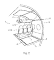
- Fig. 1 shows a single deck two aisle fuselage cross-section equipped with open frame modules 1.
- the open portion of the respective frame is adjacent to the respective aisle.
- the frame device 2 is adapted for attachment to the floor element of the aircraft at a first location in the floor plane (see also Fig. 2 ).
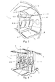
- FIG. 2 to 4 illustrate schematic views of exemplary embodiments of the present invention.
- a module for an aircraft is shown, wherein the aircraft having a fuselage structure 6 and a floor element 5.
- the floor element 5 defining a floor plane.
- the module comprises a frame device 2 wherein the frame device 2 is adapted for mounting a functional element 4.
- the frame device 2 is adapted for attachment to the floor element 5 of the aircraft at a first location 7 in the floor plane.
- the frame device 2 is adapted for attachment to the fuselage structure 6 of the aircraft at a second location 7'.
- the second location 7' is thereby not in the floor plane.
- a rail element 8 whereby the frame device 2 can be fixed relocatable respectively movable to the rail 8.
- an aircraft seat 14 or an overhead stowage bin 11 as functional element 4
- an easy relocation of the whole module 1 can be provided.
- all necessary overhead functional elements such as oxygen masks, lighting or air condition need to be adapted separately to the new seat position.
- the overhead functional elements 4, 11 will be relocated automatically.
- Fig.2 shows thereby an open frame shape 2, wherein Fig 3 and 4 illustrate a closed frame shape 2.
- Fig 3 and 4 illustrate a closed frame shape 2.
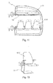
- Fig. 4 shows an exemplary embodiment of supported standing places for passengers.
- the centre of gravity of the passenger's body is thereby very high above the floor 5, so that by fixing the support 14 just on the floor section 3 will lead to high torques.
- the frame device 2 By means of the frame device 2 the frame surrounds the centre of gravity, so that high torques are avoided.
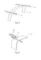
- Fig. 5 illustrates a damper element 3 integrated in a rail in order to absorb 16g loads.
- Fig. 6 shows a schematic view of a damper integrated in a frame device in order to absorb 16 g loads
- Fig. 7 shows a schematic total view of a frame device 2 of a module 1, which is movably connected to the rail element 8.
- a plurality of connection elements 3 that are connected to the rail elements 8 can be provided in order to reinforce the connection between the module 1 and the fuselage 6.
- Fig. 6 illustrates an open frame 2 with its open portion at the upper end of the surrounded area and hence describing a U-shape that allows the use of the module 1 in combination with a conventional longitudinal bin 11.
- the typical layout flexibility of the module is provided by all functional elements of a PSU being contained in a horizontal beam that is connected to the U-shaped frame 2.
- Fig. 8 shows an exemplary construction for attaching the module 1 relocatably and moveable to the fuselage structure 6 and the floor element 5.
- Rails it is possible to provide an easy constructive method for moving the frame devices 2 respectively the module 1.
- Connection elements 3 may be fixed to the frame device and are movably engaged with the rail 8.
- the frame device 2 provides thereby a closed, surrounding shape.
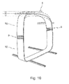
- Fig. 9 and 10 illustrate a frame device 2 that is connected to a fuselage 6, wherein an additional adapting element 9 is included.
- the adapting element 9 is connected to the frame device for adapting relative movements between the fuselage 6 and the frame device 2.
- Fig. 9 the frame device 2 adapts to the relative movements of the fuselage structure 2 by means of an adapting lever 9.
- Fig. 10 shows a schematic view of an exemplary adapting system of the module to the relative movement of the fuselage by means of a telescoping element within the frame device.
- Fig. 11 and 12 show a further exemplary embodiment of the present invention whereby the functional elements 4, 5 can be relocatably fixed to the frame device 2.
- the functional element 4 is fixed thereby adjustable to the frame device 2 to enable an adjustment.
- simple constructions can be provided, for instance by connecting the attachment elements or the functional elements eccentrically to the frame device 2.
- the functional elements here for instance the seats or the stowage bins, can be adjustable in height.
- Fig. 12 shows a more detailed view of an adjustable seat 14 that is adjustably mounted to the frame device 2.
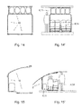
- Fig. 13 shows an exemplary view of a seat layout with reduced seat pitch made possible thanks to an increased seat height.
- the increased seat height allows for an increased luggage volume below the seats.
- Fig. 13' shows an exemplary view of a seat layout with increased seat pitch but reduced seat height for more comfort.
- the modules not in use are stowed away in one end of the cabin.
- Figs. 14 to 16 are showing some exemplary embodiments of different frame shapes.
- Fig. 14 illustrates a closed, surrounding frame device 2 consisting of several frame elements 10.
- the frame elements 10 form two closed frames, wherein in the upper rectangle frame a stowage bin 11 can be located and in the lower rectangle a seat row 14 can be installed as shown in Fig. 14' .
- Figs. 15 and 15' show an open frame device consisting of frame elements 10 with an open shape, here in a C-shape.
- a step is provided wherein in the lower stage provides a functional element 4, for instance a seat element 14, and in the upper stage a stowage bin 11 for storing items.
- Figs. 16 and 16' show a further shape of the frame device 2 consisting of several frame elements 10 wherein a lower section builds a C-shape but also containing an upper section.
- a functional element 4 can be placed, for instance a seat element 14, whereas in the upper section a stowage bin 11 can be placed as a functional element 4.
- Fig. 17 shows a front view of a cross-section of a fuselage, wherein Fig 17 . shows a three level fuselage layout.
- all differently shaped frame devices 2 are installed for the various purposes.
- the shape of the frame device shown in Fig. 11 is installed on the right and the left side for providing an optimal cabin layout with optimized space saving installation.
- 9' are installed for providing a space-saving cabin layout.
- Fig. 18 and 19 show three-dimensional views of cabin layouts according to an exemplary embodiment of the present invention.
- the frame devices 2 are curved either in longitudinal direction of the fuselage 6 or in such a way to conform to the shape of the sidewalls of the fuselage 6.
- the frame devices 2 By curving the frame devices 2 in a longitudinal direction of the fuselage 6, the field of vision of the passengers will be optimized.
- the frame shape of the frame device 2 with the fuselage structure 6 the available space in the cabin will be optimized and disturbing frame parts can follow the contour of the side panels of the aircraft structure.
- the frame shape can either be opened to the aisle side or the window side.
- the aisle between the seat rows can be kept free of any overhead elements such as stowage bins or oxygen masks, so that the available height increases the comfort level for the passengers.
- Figs. 20 and 20' show an exemplary embodiment of the present invention wherein the stowage bins 11 are accessible in longitudinal direction of the fuselage.
- the aisle between the seats 14 in longitudinal direction can be kept free..
- the turnaround time can be shortened.
- individual stowage bins 11 for each passenger can be provided.
- the overhead stowage compartments 11 can be designed as fixed bins with a floor and an upper hinged lid to give access when stowing luggage or as movable bins which move downward around a pivot or by various kinematics like parallelograms or others. Luggage can also be stored under the passenger seats.
- Fig. 21 shows an exemplary embodiment of a supply system for the functional elements 4 or the functional tools 13.
- a supply connection 15 is fixed to the frame device 2, that can be adapted to be engageable with a supply element 16 of the fuselage structure 6.
- the supply connection 15 will remain connected with the supply element 16 of the fuselage.
- the supply connection 16 can be designed like a rail, including for instance air or electricity lines.
- the supply connection 15 of the module can be in slideable contact with the feeder-rail 16 and respectively in slideable contact with the supply sources.
- FIG. 22 shows a fuselage 6' wherein the frame devices 2 of the modules 1' are installed rigidly with the fuselage primary structure 6'.
- the fuselage frames can be built integrally with the frame device 2', so that weight and complexity of the fuselage construction can be reduced.
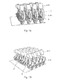
- Figs. 23 and 24 are showing further exemplary embodiments of the module 1 comprising a plurality of frame devices 2.
- an upper frame device 2 is shown, wherein a functional element 4; 11 is installed.
- An independent second frame device 2' is installed on the lower side of the module 1 wherein a second functional element 4; 14 is installed.
- the upper and lower frame devices 2, 2' can be relocated independently.
- Fig. 23 illustrates a foldable seat element 14' for reducing the space requirements for a module 1.
- Fig. 24 shows an exemplary embodiment of an installation of a stowage bin 11.
- the frame device 2 is connected to a rail element 8 by connection elements 3.
- the connection elements 3 are fixed to the fuselage structure 6 by two connecting points 3.
- the connecting line between the connecting points 3 runs through the centre of gravity of the stowage bin 11 in order to optimize the load distribution of the stowage bin 4, 11 and to minimize the torques.
Landscapes
- Engineering & Computer Science (AREA)
- Aviation & Aerospace Engineering (AREA)
- Mechanical Engineering (AREA)
- Body Structure For Vehicles (AREA)
- Seats For Vehicles (AREA)
- Vibration Prevention Devices (AREA)
- Details Of Aerials (AREA)
Priority Applications (1)
| Application Number | Priority Date | Filing Date | Title |
|---|---|---|---|
| EP13180763.8A EP2664541A3 (de) | 2005-12-29 | 2006-12-27 | Modul für ein Flugzeug |
Applications Claiming Priority (4)
| Application Number | Priority Date | Filing Date | Title |
|---|---|---|---|
| US75474505P | 2005-12-29 | 2005-12-29 | |
| EP05028664.0A EP1803645B1 (de) | 2005-12-29 | 2005-12-29 | Modul für ein Flugzeug |
| EP06841173.5A EP1966046B1 (de) | 2005-12-29 | 2006-12-27 | Modul für ein flugzeug |
| EP13180763.8A EP2664541A3 (de) | 2005-12-29 | 2006-12-27 | Modul für ein Flugzeug |
Related Parent Applications (2)
| Application Number | Title | Priority Date | Filing Date |
|---|---|---|---|
| EP06841173.5A Division-Into EP1966046B1 (de) | 2005-12-29 | 2006-12-27 | Modul für ein flugzeug |
| EP06841173.5A Division EP1966046B1 (de) | 2005-12-29 | 2006-12-27 | Modul für ein flugzeug |
Publications (2)
| Publication Number | Publication Date |
|---|---|
| EP2664541A2 true EP2664541A2 (de) | 2013-11-20 |
| EP2664541A3 EP2664541A3 (de) | 2017-12-13 |
Family
ID=36581853
Family Applications (3)
| Application Number | Title | Priority Date | Filing Date |
|---|---|---|---|
| EP05028664.0A Not-in-force EP1803645B1 (de) | 2005-12-29 | 2005-12-29 | Modul für ein Flugzeug |
| EP13180763.8A Withdrawn EP2664541A3 (de) | 2005-12-29 | 2006-12-27 | Modul für ein Flugzeug |
| EP06841173.5A Not-in-force EP1966046B1 (de) | 2005-12-29 | 2006-12-27 | Modul für ein flugzeug |
Family Applications Before (1)
| Application Number | Title | Priority Date | Filing Date |
|---|---|---|---|
| EP05028664.0A Not-in-force EP1803645B1 (de) | 2005-12-29 | 2005-12-29 | Modul für ein Flugzeug |
Family Applications After (1)
| Application Number | Title | Priority Date | Filing Date |
|---|---|---|---|
| EP06841173.5A Not-in-force EP1966046B1 (de) | 2005-12-29 | 2006-12-27 | Modul für ein flugzeug |
Country Status (8)
| Country | Link |
|---|---|
| US (2) | US9010686B2 (de) |
| EP (3) | EP1803645B1 (de) |
| JP (1) | JP2009522148A (de) |
| CN (1) | CN101351384B (de) |
| BR (1) | BRPI0620799A2 (de) |
| CA (1) | CA2632276A1 (de) |
| RU (1) | RU2414389C2 (de) |
| WO (1) | WO2007073938A1 (de) |
Cited By (1)
| Publication number | Priority date | Publication date | Assignee | Title |
|---|---|---|---|---|
| US20240263665A1 (en) * | 2023-02-07 | 2024-08-08 | B/E Aerospace, Inc. | Adjustable height fastener |
Families Citing this family (56)
| Publication number | Priority date | Publication date | Assignee | Title |
|---|---|---|---|---|
| DE102006061455A1 (de) | 2006-12-23 | 2008-06-26 | DRäGER AEROSPACE GMBH | Anordnung zumindest einer Personal Service Unit in einem Fahrzeug |
| DE102007050422B4 (de) * | 2007-10-22 | 2012-03-08 | Airbus Operations Gmbh | Flugzeugkomponentenmontagesystem |
| DE102008013790B4 (de) * | 2008-03-12 | 2014-05-28 | Airbus Operations Gmbh | Trennsystem zur Verminderung der Lichtausbreitung in einem Flugzeug |
| DE102008025390A1 (de) * | 2008-05-28 | 2010-01-28 | Airbus Deutschland Gmbh | Anordnung zum Unterteilen eines Raums in mehrere Bereiche |
| FR2935682B1 (fr) | 2008-09-05 | 2011-06-17 | Airbus France | Structure d'ensemble de siege pour aeronef et fuselage adapte |
| DE102009014606B4 (de) * | 2009-03-24 | 2012-06-06 | Airbus Operations Gmbh | Teilautomatisiertes Verfahren zur Rekonfiguration eines Kabinenlayouts |
| DE102009014598A1 (de) | 2009-03-24 | 2010-09-30 | Airbus Deutschland Gmbh | Konfektionierbare Monumente |
| DE102009014599A1 (de) * | 2009-03-24 | 2010-09-30 | Airbus Deutschland Gmbh | Integration von Versorgungsfunktionen in ein Staufach |
| DE102009023401B4 (de) * | 2009-05-29 | 2014-06-26 | Airbus Operations Gmbh | Halter zur Befestigung einer zur Montage in einem Flugzeugrumpfelement vorgesehenen Interieurkomponente an einer Transportvorrichtung sowie Transportvorrichtung |
| DE102009023391A1 (de) * | 2009-05-29 | 2010-12-02 | Airbus Deutschland Gmbh | Verfahren und System zur Montage von Interieurkomponenten in einem Flugzeug |
| DE102009023400B4 (de) * | 2009-05-29 | 2014-07-10 | Airbus Operations Gmbh | Haltersystem zur Befestigung einer Flugzeuginterieurkomponente an einer Transportvorrichtung sowie einer Flugzeugstruktur |
| DE102009043314B4 (de) | 2009-09-28 | 2018-12-20 | Airbus Operations Gmbh | Kabinenausstattungskomponentenanschlusssystem und Verfahren zur Modifikation einer Passagierkabinenkonfiguration |
| US8262022B2 (en) * | 2009-12-15 | 2012-09-11 | The Boeing Company | Overhead stowage bin load transfer and balance system |
| US8590838B2 (en) | 2010-04-20 | 2013-11-26 | Be Intellectual Property, Inc. | Aircraft interior lavatory |
| DE102010035375A1 (de) * | 2010-08-25 | 2012-03-01 | Airbus Operations Gmbh | Anordnung zum Aufnehmen von Passagieren in einem Verkehrsmittel |
| DE102011009806A1 (de) * | 2011-01-31 | 2012-08-02 | Airbus Operations Gmbh | Rumpfsegment für einen Luftfahrzeugrumpf, Luftfahrzeugrumpf und Luftfahrzeug |
| SG194104A1 (en) | 2011-04-04 | 2013-11-29 | C & D Zodiac Inc | Seat shell and integrated overhead storage bin |
| US9938015B2 (en) | 2011-04-04 | 2018-04-10 | C&D Zodiac, Inc. | Shared entrance seating arrangement |
| US20190023401A1 (en) * | 2011-04-04 | 2019-01-24 | C&D Zodiac, Inc. | Aircraft storage bin assembly with upper and lower bins |
| USD749709S1 (en) | 2011-04-18 | 2016-02-16 | B/E Aerospace, Inc. | Aircraft interior lavatory |
| DE102011110010A1 (de) * | 2011-08-11 | 2013-02-14 | Airbus Operations Gmbh | Passagierversorgungsmodul mit integrierter Kabinenbeleuchtung |
| WO2013125218A1 (ja) | 2012-02-23 | 2013-08-29 | 横浜ゴム株式会社 | 航空機の化粧室ユニットの設置方法および航空機 |
| DE102012005148A1 (de) | 2012-03-13 | 2013-09-19 | Airbus Operations Gmbh | Passagierkabine für ein Fahrzeug und Fahrzeug mit einer Passagierkabine |
| US9359078B2 (en) * | 2012-03-28 | 2016-06-07 | B/E Aerospace, Inc. | Aircraft galley monument structure |
| US20130290221A1 (en) * | 2012-04-25 | 2013-10-31 | Satish Jindel | Passenger aircraft overhead bin system and method |
| JP5825192B2 (ja) | 2012-05-11 | 2015-12-02 | 横浜ゴム株式会社 | 航空機用化粧室ユニットおよびその配置構造 |
| JP5849855B2 (ja) | 2012-05-11 | 2016-02-03 | 横浜ゴム株式会社 | 航空機用化粧室ユニットおよびその配置構造 |
| CA2879022C (en) * | 2012-07-17 | 2022-01-25 | B/E Aerospace, Inc. | Space efficient partition assembly for commercial aircraft |
| JP2014076713A (ja) | 2012-10-10 | 2014-05-01 | Yokohama Rubber Co Ltd:The | 航空機用化粧室ユニット |
| JP5825240B2 (ja) | 2012-10-12 | 2015-12-02 | 横浜ゴム株式会社 | 航空機用化粧室ユニット |
| US9889936B2 (en) * | 2012-10-30 | 2018-02-13 | The Boeing Company | Curved seating layout |
| US9359076B2 (en) | 2013-02-11 | 2016-06-07 | B/E Aerospace, Inc. | Compact aircraft galley and lavatory arrangement and articulating lavatory partition for an aircraft |
| US20150008283A1 (en) * | 2013-07-03 | 2015-01-08 | Zodiac Aerotechnics | Aircraft seating unit with fixture member |
| EP2821345A1 (de) * | 2013-07-03 | 2015-01-07 | Zodiac Aerotechnics | Flugzeugsitzeinheit mit Halterungselement |
| GB2516433B (en) | 2013-07-19 | 2016-02-17 | British Airways Plc | Aircraft passenger seat fixing system |
| EP2848526B1 (de) * | 2013-09-11 | 2016-11-30 | Airbus Operations GmbH | Flugzeugkabinentrennwandmonument mit Staufach und Verfahren |
| US9561760B2 (en) * | 2013-10-11 | 2017-02-07 | The Boeing Company | Modular equipment center distributed equipment packaging truss |
| US9738402B2 (en) * | 2014-06-30 | 2017-08-22 | The Boeing Company | Flight test equipment installation system and method |
| JP6105064B2 (ja) * | 2014-09-24 | 2017-03-29 | 株式会社ジャムコ | 航空機用ギャレーユニット |
| CN104330026B (zh) * | 2014-10-29 | 2017-06-09 | 上海飞机制造有限公司 | 飞机座椅滑轨位置的检测装置及其测量方法 |
| AT516642A1 (de) * | 2014-12-15 | 2016-07-15 | Facc Ag | Elektrisch betätigbares bewegbares Überkopf-Gepäckfach für Flugzeuge |
| CN107848626B (zh) * | 2015-04-08 | 2021-03-23 | 赛峰座椅美国有限责任公司 | 通用休息座椅 |
| DE102015114762A1 (de) | 2015-09-03 | 2017-03-09 | Recaro Aircraft Seating Gmbh & Co. Kg | Flugzeugsitzvorrichtung mit klappbarem Flugzeugsitz |
| WO2017129692A1 (fr) * | 2016-01-26 | 2017-08-03 | Zodiac Seats France | Butée d'arrêt pour siège d'avion |
| DE102016108288A1 (de) * | 2016-05-04 | 2017-11-09 | Recaro Aircraft Seating Gmbh & Co. Kg | Rettungswestentasche |
| WO2017200610A1 (en) * | 2016-05-18 | 2017-11-23 | Airbus Group Hq, Inc. | Self-piloted aircraft for passenger or cargo transportation |
| WO2017201207A1 (en) * | 2016-05-18 | 2017-11-23 | Airbus Group Hq Inc. Dba A3 By Airbus Group | Systems, devices, and methods for a modular passenger aircraft cabin and design thereof |
| DE102016208516A1 (de) * | 2016-05-18 | 2017-11-23 | Siemens Aktiengesellschaft | Fahrzeugsitzanordnung und damit ausgestattetes Schienenfahrzeug |
| US9936272B1 (en) * | 2016-09-30 | 2018-04-03 | The Boeing Company | Apparatuses and methods for acoustically exciting a face panel of a stowage bin inside a vehicle |
| WO2019070481A1 (en) * | 2017-10-04 | 2019-04-11 | C&D Zodiac, Inc. | AIRCRAFT STORAGE COMPARTMENT ASSEMBLY WITH UPPER AND LOWER COMPARTMENTS |
| US10933967B2 (en) * | 2017-12-15 | 2021-03-02 | Airbus Americas, Inc. | Partition wall in cabin of aircraft supporting monuments |
| JP7006552B2 (ja) | 2018-09-25 | 2022-01-24 | 横浜ゴム株式会社 | 航空機用化粧室ユニット |
| US11407484B2 (en) | 2019-06-14 | 2022-08-09 | Airbus Americas, Inc. | Standard cabin monument sub-structure |
| US11465747B2 (en) * | 2019-07-31 | 2022-10-11 | The Boeing Company | Overhead support platform system for a vehicle |
| CA3200629A1 (en) * | 2020-12-01 | 2022-06-09 | Mark Robert Hacker | Aircraft seating module |
| US20220234742A1 (en) * | 2021-01-27 | 2022-07-28 | Antonio Alvarez | Aircraft Sanitizer |
Citations (4)
| Publication number | Priority date | Publication date | Assignee | Title |
|---|---|---|---|---|
| DE4301681C1 (de) | 1993-01-22 | 1994-10-20 | Deutsche Aerospace Airbus | Rohrverzweigung zwischen einer Luftleitung und einer Luftdusche |
| DE19502658C1 (de) | 1995-01-28 | 1996-03-28 | Daimler Benz Aerospace Airbus | Anordnung zum Versorgen von Passagieren in einer Passagierkabine, insbesondere in einem Flugzeug |
| DE19534025C1 (de) | 1995-09-14 | 1996-11-28 | Daimler Benz Aerospace Airbus | Versorgungseinheit für Passagiere, insbesondere in einer Passagierkabine eines Flugzeuges |
| DE19533981C1 (de) | 1995-09-14 | 1996-12-19 | Daimler Benz Aerospace Airbus | Versorgungseinheit für Passagiere, insbesondere in einer Passagierkabine eines Flugzeuges |
Family Cites Families (108)
| Publication number | Priority date | Publication date | Assignee | Title |
|---|---|---|---|---|
| US628605A (en) * | 1898-10-17 | 1899-07-11 | Fanny R Ottenheimer | Hat-holding attachment for chairs. |
| US747489A (en) * | 1903-06-13 | 1903-12-22 | Myron Rounds | Electric car. |
| US1378210A (en) * | 1920-08-06 | 1921-05-17 | Alfred L Berry | Collapsible luggage-holder |
| US1829486A (en) * | 1929-02-16 | 1931-10-27 | Kimbrig Louis | Hat and coat holder |
| US2067585A (en) * | 1934-02-14 | 1937-01-12 | Curtiss Wright Corp | Gunner's seat and mounting |
| US2383173A (en) * | 1942-10-29 | 1945-08-21 | Budd Edward G Mfg Co | Airplane seat |
| US2985413A (en) * | 1958-07-08 | 1961-05-23 | Haraldo Juan Albrecht V Widman | Multi-directional anti-g device |
| US3142461A (en) * | 1960-05-26 | 1964-07-28 | A T S Company Ltd | Internal fittings of aircraft |
| US3173627A (en) * | 1963-03-08 | 1965-03-16 | Leonard A Cohen | Compostie space vehicle |
| US3610560A (en) * | 1969-12-03 | 1971-10-05 | Alan G Dillabough | Litter bag holder |
| US3632029A (en) * | 1969-12-29 | 1972-01-04 | May B Sonner | Litter bag |
| US3630566A (en) * | 1970-05-13 | 1971-12-28 | American Seating Co | End-supported vehicle seat |
| US3817434A (en) * | 1972-12-14 | 1974-06-18 | J Dickman | Concealed auto litter receptacle |
| DE2630210C3 (de) * | 1976-07-05 | 1979-10-18 | Hans Guido Dr. 8000 Muenchen Mutke | Vorrichtung zur liegenden Beförderung von Personen insbesondere in Luftfahrzeugen |
| US4216927A (en) * | 1978-03-06 | 1980-08-12 | Air Cargo Equipment Corporation | Baggage handling and storage system |
| US4175723A (en) * | 1978-04-03 | 1979-11-27 | Great Lakes Carbon Corporation | Method and apparatus for neutralizing the effect of accelerating and decelerating forces |
| US4624502A (en) * | 1984-11-21 | 1986-11-25 | Boole Leon J | Portable drawer assembly |
| SU1362300A1 (ru) | 1986-01-03 | 2005-02-10 | В.А. Кувшинов | Устройство для подвески экрана в салоне самолета |
| US4799631A (en) * | 1987-02-18 | 1989-01-24 | Atr International, Inc. | Aircraft shell module |
| GB8707485D0 (en) * | 1987-03-28 | 1987-04-29 | Flight Equipment & Eng Ltd | Armrest arrangements for vehicle seating |
| FR2630073B1 (fr) * | 1988-04-14 | 1990-07-13 | Cimt Lorraine | Voiture ferroviaire a deux etages |
| GB8821066D0 (en) * | 1988-09-08 | 1988-10-05 | Magerik Ltd | Seating |
| US5015033A (en) * | 1989-12-20 | 1991-05-14 | Deana Winters | Underseat receptacle for purses and other possessions |
| US5083727A (en) * | 1990-01-02 | 1992-01-28 | The Boeing Company | Aircraft cabin system for selectivley locating interior units |
| US5104065A (en) * | 1990-02-20 | 1992-04-14 | The Boeing Company | Readily convertible aircraft passenger seats |
| US5131606A (en) * | 1991-04-01 | 1992-07-21 | Arnold Nordstrom | Seat pallet and cargo pallet restraining system |
| DE9116031U1 (de) | 1991-10-26 | 1992-03-12 | Frick, Hans-Ruedi, Weinfelden | Flugzeugsitz |
| JP3241492B2 (ja) * | 1992-08-03 | 2001-12-25 | トヨタ自動車株式会社 | 自動車部品の組付作業用シート |
| US5597139A (en) * | 1994-04-15 | 1997-01-28 | Burns Aerospace Corporation | Convertible passenger seat assembly |
| US5573288A (en) * | 1994-12-19 | 1996-11-12 | Sif Products Group Inc. | Portable seat cushion and storage device |
| JPH0920293A (ja) * | 1995-07-10 | 1997-01-21 | Mitsubishi Heavy Ind Ltd | 航空機の客室の床の構造 |
| US6340136B1 (en) * | 1995-08-07 | 2002-01-22 | Fuselage Engineering Service, Ltd. | Compact storing and retrieving apparatus particularly useful for aircraft |
| US5716026A (en) * | 1995-08-14 | 1998-02-10 | Pascasio; Vidal | High-capacity, high-comfort split-level seating for transport and stationary applications |
| DE19534024C2 (de) | 1995-09-14 | 1997-07-10 | Daimler Benz Aerospace Airbus | Sitzgruppe, insbesondere in einer Passagierkabine eines Flugzeuges |
| DE29515306U1 (de) | 1995-09-25 | 1995-11-23 | Franz Kalff Gmbh, 53881 Euskirchen | Nothilfetasche |
| DE19540929C2 (de) * | 1995-11-03 | 1997-08-14 | Daimler Benz Aerospace Airbus | Gepäckablage in einer Passagierkabine, insbesondere in einem Verkehrsflugzeug |
| US5772370A (en) * | 1995-11-22 | 1998-06-30 | Moore; Donal | Retractable and/or removable net type cargo restraining system |
| US5740989A (en) * | 1995-12-26 | 1998-04-21 | Daines; Paul H. | Lay down seat mechanism |
| FR2755656B1 (fr) | 1996-11-08 | 1998-12-31 | Peugeot | Dispositif destine au rangement ou a la retenue d'objets dans un vehicule automobile |
| US5816650A (en) * | 1997-02-21 | 1998-10-06 | Lear Corporation | Underseat storage bin for motor vehicles |
| US5820210A (en) * | 1997-05-22 | 1998-10-13 | Shipman; Russell P. | Storage device for seating |
| US5927800A (en) * | 1997-09-08 | 1999-07-27 | Stallworth; Marcus | Theater trash bag |
| US6082816A (en) * | 1997-10-08 | 2000-07-04 | The Jeremy Group | Chair storage unit |
| US6053570A (en) * | 1998-05-21 | 2000-04-25 | Stern; Cindy Jane | Detachable storage device positionable under theater seats |
| US6056239A (en) * | 1998-08-12 | 2000-05-02 | Carlos Martinez Celis Cantu | Convertible seating and sleeping accommodations for aircraft |
| DE19839701C2 (de) * | 1998-09-01 | 2003-07-24 | Airbus Gmbh | Gepäckablagenanordnung in einer Flugzeugpassagierkabine |
| US8763954B2 (en) * | 2007-12-17 | 2014-07-01 | Arjuna Indraeswaran Rajasingham | Vehicle occupant support |
| US20010050499A1 (en) * | 2000-02-12 | 2001-12-13 | Deloach Vera A. | School bus underseat storage container and method |
| DE10008258B4 (de) * | 2000-02-23 | 2006-07-13 | Airbus Deutschland Gmbh | Passagierstützvorrichtung für eine Flugzeugpassagierkabine |
| ES2226993T3 (es) * | 2000-03-09 | 2005-04-01 | Airbus Deutschland Gmbh | Asiento de pasajero de avion para una cabina de pasajeros de un avion. |
| DE10052594C2 (de) | 2000-03-09 | 2002-03-21 | Airbus Gmbh | Vorrichtung zur Orientierung in einer Passagierkabine eines Flugzeuges |
| ES2226992T3 (es) * | 2000-03-09 | 2005-04-01 | Airbus Deutschland Gmbh | Asiento de pasajero con medios de seguridad. |
| DE10052593A1 (de) | 2000-03-09 | 2001-09-20 | Eads Airbus Gmbh | Passagiersitz mit einer Vorrichtung zur Afnahme von sitzplatzbezogenem Zubehör und Abfall |
| DE10052591B4 (de) | 2000-03-09 | 2005-01-27 | Airbus Deutschland Gmbh | Fluggastsitz für eine Flugzeugpassagierkabine |
| DE10052595A1 (de) | 2000-03-09 | 2001-09-20 | Eads Airbus Gmbh | Passagiersitz mit Sicherheitsmitteln |
| ATE276130T1 (de) * | 2000-03-09 | 2004-10-15 | Airbus Gmbh | Passagiersitz mit einer vorrichtung zur aufnahme von sitzplatzbezogenem zubehör und abfall |
| ES2232529T3 (es) * | 2000-03-09 | 2005-06-01 | Airbus Deutschland Gmbh | Fila de asientos con dispositivo para la orientacion en una cabina de pasajeros de un avion. |
| JP2001315581A (ja) * | 2000-05-09 | 2001-11-13 | Fuji Heavy Ind Ltd | 車両用荷物保持装置 |
| US6609744B2 (en) * | 2000-06-29 | 2003-08-26 | Collins & Aikman Products Co. | Collapsible storage apparatus for vehicle cargo compartments |
| DE10056043C2 (de) * | 2000-11-11 | 2003-04-10 | Daimler Chrysler Ag | Fahrzeug, insbesondere Kombifahrzeug |
| JP3573707B2 (ja) * | 2000-11-22 | 2004-10-06 | 株式会社ジャムコ | 航空機用拡張式ラバトリーユニット |
| US6601798B2 (en) * | 2001-06-26 | 2003-08-05 | The Boeing Company | Seat track mounted passenger interface |
| US6581876B2 (en) * | 2001-07-25 | 2003-06-24 | The Boeing Company | Aircraft multi-function overhead space access module |
| US6494404B1 (en) * | 2001-08-14 | 2002-12-17 | John C. Meyer | Passenger airplane container system |
| DE10143438A1 (de) * | 2001-09-05 | 2003-03-27 | Recaro Aircraft Seating Gmbh | Schwimmwestentasche |
| US6834833B2 (en) * | 2001-10-02 | 2004-12-28 | The Boeing Company | Twin aisle small airplane |
| AT413812B (de) * | 2001-10-17 | 2006-06-15 | Fischer Adv Components Gmbh | Aufhängevorrichtung für absenkbare gebäckablagebehälter |
| DE20120481U1 (de) | 2001-12-18 | 2003-05-15 | HYMER-LEICHTMETALLBAU GMBH & CO. KG, 88239 Wangen | Gepäckfach für Land-, Wasser- und Luftfahrzeuge |
| DE10214104C1 (de) * | 2002-03-28 | 2003-12-11 | Airbus Gmbh | Fahrzeugsitz, insbesondere Fluggastsitz |
| FR2840281B1 (fr) * | 2002-05-30 | 2004-12-17 | Airbus | Coffre a bagages pour aeronef |
| DE10224048B4 (de) | 2002-05-31 | 2006-07-13 | Airbus Deutschland Gmbh | Passagiersitz, insbesondere für ein Verkehrsflugzeug |
| US6899299B2 (en) * | 2002-07-26 | 2005-05-31 | The Boeing Company | Luggage bins and aircraft passenger cabin ceilings |
| US6776373B1 (en) * | 2003-02-19 | 2004-08-17 | Robert N. Talmage, Jr. | Aircraft escape cabin |
| US7066551B2 (en) * | 2003-04-28 | 2006-06-27 | Be Aerospace, Inc. | Curved beam aircraft passenger seat |
| US7252267B2 (en) * | 2003-10-17 | 2007-08-07 | The Boeing Company | Aircraft archway architecture |
| US20060006704A1 (en) * | 2003-12-15 | 2006-01-12 | Be Aerospace, Inc. | Vehicle seating with storage feature |
| DE102004002169B4 (de) | 2004-01-12 | 2007-06-28 | Airbus Deutschland Gmbh | Fahrzeugsitz, insbesondere Fluggastsitz |
| US7934679B2 (en) | 2004-02-20 | 2011-05-03 | Singapore Airlines Limited | Aircraft cabin |
| DE102004012480A1 (de) | 2004-03-15 | 2005-10-06 | Airbus Deutschland Gmbh | Klappsitz abwärts |
| EP1577152B1 (de) * | 2004-03-15 | 2010-06-09 | Airbus Operations GmbH | Klappsitz abwärts |
| US6883753B1 (en) * | 2004-03-25 | 2005-04-26 | The Boeing Company | Overhead bin and monument attachment support system |
| US7188805B2 (en) * | 2004-03-27 | 2007-03-13 | The Boeing Company | Continuous power bus for seat power |
| FR2869289B1 (fr) * | 2004-04-27 | 2007-07-13 | Eads Sogerma Services Sa | Amenagement interieur des parois du fuselage d'un aeronef. |
| DE202004008069U1 (de) | 2004-05-13 | 2004-07-29 | Tricon Aktiengesellschaft | Flugzeugsitz mit integriertem Handgepäckfach |
| DE102004025125A1 (de) | 2004-05-21 | 2005-12-15 | Airbus Deutschland Gmbh | Fluggastsitz mit integriertem Federelement |
| EP1598270B1 (de) * | 2004-05-21 | 2009-04-29 | Airbus Deutschland GmbH | Fluggastsitz mit integriertem Federelement |
| DE102004025982B4 (de) | 2004-05-27 | 2008-12-04 | Airbus Deutschland Gmbh | Zweiholmerchassis für Fluggastsitz |
| US7232095B2 (en) * | 2004-09-08 | 2007-06-19 | The Boeing Company | Overhead rest assembly |
| US7261786B2 (en) * | 2004-09-16 | 2007-08-28 | The Boeing Company | Filament wound crew rest enclosure structure |
| US7201421B2 (en) * | 2005-02-11 | 2007-04-10 | Lear Corporation | Rear vehicle storage system |
| WO2006094091A2 (en) * | 2005-02-28 | 2006-09-08 | Ipventure, Inc. | Comfortable seating arrangements with easy access |
| DE102005015142A1 (de) * | 2005-03-31 | 2006-10-05 | Recaro Aircraft Seating Gmbh & Co. Kg | Komfortsystem für einen Sitz, insbesondere für in Reihe hintereinander angeordnete Fahr- und Fluggastsitze |
| US7455263B2 (en) * | 2005-04-22 | 2008-11-25 | The Boeing Company | Airplane interior systems |
| US7712704B2 (en) * | 2005-06-07 | 2010-05-11 | Airbus | Arrangement of seats and baggage compartments in an aircraft cabin |
| US7703718B2 (en) * | 2005-06-10 | 2010-04-27 | Airbus | Aircraft cabin arrangement and storage unit |
| GB0512541D0 (en) * | 2005-06-20 | 2005-07-27 | James Park Associates Ltd | Aircraft interior module |
| DE102005042403B8 (de) * | 2005-09-06 | 2008-01-10 | Airbus Deutschland Gmbh | Modulares Sitzsystem für ein Fahrzeug |
| US7770523B2 (en) * | 2005-10-07 | 2010-08-10 | University Of South Florida | Interactive amusement park attraction vehicle |
| DE102006048998A1 (de) * | 2005-12-29 | 2007-07-12 | Airbus Deutschland Gmbh | Teleskopartiges Gepäckfach |
| ES1063217Y (es) * | 2006-02-20 | 2007-01-16 | Fernandez Javier Valverde | Asiento movil para vehiculos |
| DE102006039291A1 (de) * | 2006-08-22 | 2008-03-13 | Airbus Deutschland Gmbh | Rahmenelement, Gepäckfach sowie Verfahren zur Montage eines Gepäckfachs in einem Flugzeug |
| US7723935B2 (en) * | 2006-08-25 | 2010-05-25 | The Boeing Company | System and method for compartment control |
| US7871039B2 (en) * | 2007-05-22 | 2011-01-18 | The Boeing Company | Modular passenger seat for an aircraft |
| US7523993B1 (en) * | 2007-11-23 | 2009-04-28 | Nova Bus, Division De Groupe Volvo Canada Inc. | Passenger dorsal support |
| DE102009014598A1 (de) * | 2009-03-24 | 2010-09-30 | Airbus Deutschland Gmbh | Konfektionierbare Monumente |
| DE102009024157A1 (de) * | 2009-06-08 | 2011-03-03 | Airbus Operations Gmbh | System und Verfahren zum Herstellen einer Fahrzeugkabine |
| US20120074258A1 (en) * | 2010-09-23 | 2012-03-29 | Be Intellectual Property, Inc. | Integrated aircraft interior |
| SG194104A1 (en) * | 2011-04-04 | 2013-11-29 | C & D Zodiac Inc | Seat shell and integrated overhead storage bin |
-
2005
- 2005-12-29 EP EP05028664.0A patent/EP1803645B1/de not_active Not-in-force
-
2006
- 2006-12-27 WO PCT/EP2006/012545 patent/WO2007073938A1/en active Application Filing
- 2006-12-27 RU RU2008130999A patent/RU2414389C2/ru not_active IP Right Cessation
- 2006-12-27 EP EP13180763.8A patent/EP2664541A3/de not_active Withdrawn
- 2006-12-27 BR BRPI0620799-5A patent/BRPI0620799A2/pt not_active IP Right Cessation
- 2006-12-27 CA CA 2632276 patent/CA2632276A1/en not_active Abandoned
- 2006-12-27 US US12/087,328 patent/US9010686B2/en active Active
- 2006-12-27 CN CN2006800499494A patent/CN101351384B/zh not_active Expired - Fee Related
- 2006-12-27 JP JP2008547897A patent/JP2009522148A/ja active Pending
- 2006-12-27 EP EP06841173.5A patent/EP1966046B1/de not_active Not-in-force
-
2015
- 2015-03-17 US US14/660,268 patent/US20150259067A1/en not_active Abandoned
Patent Citations (4)
| Publication number | Priority date | Publication date | Assignee | Title |
|---|---|---|---|---|
| DE4301681C1 (de) | 1993-01-22 | 1994-10-20 | Deutsche Aerospace Airbus | Rohrverzweigung zwischen einer Luftleitung und einer Luftdusche |
| DE19502658C1 (de) | 1995-01-28 | 1996-03-28 | Daimler Benz Aerospace Airbus | Anordnung zum Versorgen von Passagieren in einer Passagierkabine, insbesondere in einem Flugzeug |
| DE19534025C1 (de) | 1995-09-14 | 1996-11-28 | Daimler Benz Aerospace Airbus | Versorgungseinheit für Passagiere, insbesondere in einer Passagierkabine eines Flugzeuges |
| DE19533981C1 (de) | 1995-09-14 | 1996-12-19 | Daimler Benz Aerospace Airbus | Versorgungseinheit für Passagiere, insbesondere in einer Passagierkabine eines Flugzeuges |
Cited By (1)
| Publication number | Priority date | Publication date | Assignee | Title |
|---|---|---|---|---|
| US20240263665A1 (en) * | 2023-02-07 | 2024-08-08 | B/E Aerospace, Inc. | Adjustable height fastener |
Also Published As
| Publication number | Publication date |
|---|---|
| US9010686B2 (en) | 2015-04-21 |
| EP1966046B1 (de) | 2019-04-17 |
| EP1803645B1 (de) | 2020-03-11 |
| JP2009522148A (ja) | 2009-06-11 |
| CA2632276A1 (en) | 2007-07-05 |
| RU2414389C2 (ru) | 2011-03-20 |
| CN101351384A (zh) | 2009-01-21 |
| WO2007073938B1 (en) | 2007-08-09 |
| BRPI0620799A2 (pt) | 2011-11-22 |
| US20090283636A1 (en) | 2009-11-19 |
| US20150259067A1 (en) | 2015-09-17 |
| EP1803645A1 (de) | 2007-07-04 |
| CN101351384B (zh) | 2010-09-29 |
| EP2664541A3 (de) | 2017-12-13 |
| EP1966046A1 (de) | 2008-09-10 |
| RU2008130999A (ru) | 2010-02-10 |
| WO2007073938A1 (en) | 2007-07-05 |
Similar Documents
| Publication | Publication Date | Title |
|---|---|---|
| EP1966046B1 (de) | Modul für ein flugzeug | |
| US20200298976A1 (en) | Aircraft lounge assembly | |
| EP3345834B1 (de) | Überkopf-gepäckablage in flugzeuge und flugzeug mit einer solchen | |
| EP2134596B1 (de) | Unterflursystem für ein flugzeug | |
| US7922119B2 (en) | Telescopic stowage bin | |
| US8413268B2 (en) | Rest arrangement | |
| EP3835205B1 (de) | Sitzeinheit und fahrgastsitzanordnung | |
| US11312495B2 (en) | Compact seat assembly for a vehicle | |
| US20210107656A1 (en) | Seating systems and methods for an internal cabin of an aircraft | |
| EP3126241B1 (de) | Sitzanordnung mit gemeinsam genutzten eingang | |
| EP3691970A1 (de) | Staubehälteranordnung eines flugzeugs mit oberen und unteren behältern | |
| EP4015385A1 (de) | Flugzeugpassagiersitzreihe mit flugbegleitersitz |
Legal Events
| Date | Code | Title | Description |
|---|---|---|---|
| PUAI | Public reference made under article 153(3) epc to a published international application that has entered the european phase |
Free format text: ORIGINAL CODE: 0009012 |
|
| 17P | Request for examination filed |
Effective date: 20130816 |
|
| AC | Divisional application: reference to earlier application |
Ref document number: 1966046 Country of ref document: EP Kind code of ref document: P |
|
| AK | Designated contracting states |
Kind code of ref document: A2 Designated state(s): AT BE BG CH CY CZ DE DK EE ES FI FR GB GR HU IE IS IT LI LT LU LV MC NL PL PT RO SE SI SK TR |
|
| RIN1 | Information on inventor provided before grant (corrected) |
Inventor name: SCHUMACHER, MARKUS Inventor name: ZANEBONI, JASON Inventor name: HAACK, CORD Inventor name: SAINT-JALMES, BRUNO Inventor name: REZAG, ANDRE Inventor name: MUIN, ANDREW Inventor name: CARR, MICHAEL |
|
| PUAL | Search report despatched |
Free format text: ORIGINAL CODE: 0009013 |
|
| AK | Designated contracting states |
Kind code of ref document: A3 Designated state(s): AT BE BG CH CY CZ DE DK EE ES FI FR GB GR HU IE IS IT LI LT LU LV MC NL PL PT RO SE SI SK TR |
|
| RIC1 | Information provided on ipc code assigned before grant |
Ipc: B64D 11/00 20060101ALN20171108BHEP Ipc: B64D 11/06 20060101AFI20171108BHEP |
|
| STAA | Information on the status of an ep patent application or granted ep patent |
Free format text: STATUS: THE APPLICATION HAS BEEN WITHDRAWN |
|
| 18W | Application withdrawn |
Effective date: 20190517 |