EP2641392B1 - Amélioration d'un système de mise au point automatique pour des affichages de réalité augmentée - Google Patents
Amélioration d'un système de mise au point automatique pour des affichages de réalité augmentée Download PDFInfo
- Publication number
- EP2641392B1 EP2641392B1 EP11842082.7A EP11842082A EP2641392B1 EP 2641392 B1 EP2641392 B1 EP 2641392B1 EP 11842082 A EP11842082 A EP 11842082A EP 2641392 B1 EP2641392 B1 EP 2641392B1
- Authority
- EP
- European Patent Office
- Prior art keywords
- user
- focal
- lens
- focal region
- virtual
- Prior art date
- Legal status (The legal status is an assumption and is not a legal conclusion. Google has not performed a legal analysis and makes no representation as to the accuracy of the status listed.)
- Active
Links
- 230000003190 augmentative effect Effects 0.000 title claims description 24
- 230000006872 improvement Effects 0.000 title description 5
- 238000012545 processing Methods 0.000 claims description 146
- 238000000034 method Methods 0.000 claims description 91
- 239000007788 liquid Substances 0.000 claims description 39
- 230000002708 enhancing effect Effects 0.000 claims description 5
- 230000004927 fusion Effects 0.000 claims description 4
- 230000002123 temporal effect Effects 0.000 claims description 3
- 230000008569 process Effects 0.000 description 62
- 230000003287 optical effect Effects 0.000 description 49
- 238000004891 communication Methods 0.000 description 35
- 238000006073 displacement reaction Methods 0.000 description 23
- 238000005516 engineering process Methods 0.000 description 22
- 230000000007 visual effect Effects 0.000 description 21
- 230000008859 change Effects 0.000 description 20
- 239000012528 membrane Substances 0.000 description 19
- 230000033001 locomotion Effects 0.000 description 18
- 230000004438 eyesight Effects 0.000 description 16
- 230000010287 polarization Effects 0.000 description 14
- 239000011521 glass Substances 0.000 description 11
- 238000010586 diagram Methods 0.000 description 10
- 238000005286 illumination Methods 0.000 description 8
- 230000009471 action Effects 0.000 description 7
- 210000003128 head Anatomy 0.000 description 7
- 239000000758 substrate Substances 0.000 description 6
- 230000006870 function Effects 0.000 description 5
- 238000003384 imaging method Methods 0.000 description 5
- 201000010041 presbyopia Diseases 0.000 description 5
- 210000001747 pupil Anatomy 0.000 description 5
- 241001481833 Coryphaena hippurus Species 0.000 description 4
- 241000282412 Homo Species 0.000 description 4
- 230000000694 effects Effects 0.000 description 4
- 238000009877 rendering Methods 0.000 description 4
- 238000004458 analytical method Methods 0.000 description 3
- 239000012530 fluid Substances 0.000 description 3
- 239000000463 material Substances 0.000 description 3
- 230000008447 perception Effects 0.000 description 3
- 230000002093 peripheral effect Effects 0.000 description 3
- 230000004044 response Effects 0.000 description 3
- 210000001525 retina Anatomy 0.000 description 3
- 238000010408 sweeping Methods 0.000 description 3
- 230000001133 acceleration Effects 0.000 description 2
- 239000011149 active material Substances 0.000 description 2
- 230000000712 assembly Effects 0.000 description 2
- 238000000429 assembly Methods 0.000 description 2
- 210000004087 cornea Anatomy 0.000 description 2
- 239000004205 dimethyl polysiloxane Substances 0.000 description 2
- 239000000428 dust Substances 0.000 description 2
- 230000001747 exhibiting effect Effects 0.000 description 2
- 210000004247 hand Anatomy 0.000 description 2
- 238000013507 mapping Methods 0.000 description 2
- 238000005259 measurement Methods 0.000 description 2
- 230000010363 phase shift Effects 0.000 description 2
- 239000004033 plastic Substances 0.000 description 2
- 229920000435 poly(dimethylsiloxane) Polymers 0.000 description 2
- 208000014733 refractive error Diseases 0.000 description 2
- 210000000707 wrist Anatomy 0.000 description 2
- 241000251468 Actinopterygii Species 0.000 description 1
- 229920002799 BoPET Polymers 0.000 description 1
- XUIMIQQOPSSXEZ-UHFFFAOYSA-N Silicon Chemical compound [Si] XUIMIQQOPSSXEZ-UHFFFAOYSA-N 0.000 description 1
- 241000287181 Sturnus vulgaris Species 0.000 description 1
- 230000005540 biological transmission Effects 0.000 description 1
- 230000004397 blinking Effects 0.000 description 1
- 210000000988 bone and bone Anatomy 0.000 description 1
- 239000002131 composite material Substances 0.000 description 1
- 230000001419 dependent effect Effects 0.000 description 1
- 238000001514 detection method Methods 0.000 description 1
- 210000005069 ears Anatomy 0.000 description 1
- 230000007613 environmental effect Effects 0.000 description 1
- 230000004424 eye movement Effects 0.000 description 1
- 238000009499 grossing Methods 0.000 description 1
- 238000003331 infrared imaging Methods 0.000 description 1
- 230000010354 integration Effects 0.000 description 1
- 230000003993 interaction Effects 0.000 description 1
- 239000010985 leather Substances 0.000 description 1
- 239000004973 liquid crystal related substance Substances 0.000 description 1
- 230000004807 localization Effects 0.000 description 1
- 210000003205 muscle Anatomy 0.000 description 1
- 208000001491 myopia Diseases 0.000 description 1
- 230000006855 networking Effects 0.000 description 1
- 230000004297 night vision Effects 0.000 description 1
- 210000004279 orbit Anatomy 0.000 description 1
- -1 polydimethylsiloxane Polymers 0.000 description 1
- 230000002040 relaxant effect Effects 0.000 description 1
- 238000005070 sampling Methods 0.000 description 1
- 238000007789 sealing Methods 0.000 description 1
- 230000035945 sensitivity Effects 0.000 description 1
- 230000001953 sensory effect Effects 0.000 description 1
- 229910052710 silicon Inorganic materials 0.000 description 1
- 239000010703 silicon Substances 0.000 description 1
- 229920002545 silicone oil Polymers 0.000 description 1
- 230000005236 sound signal Effects 0.000 description 1
- 238000012546 transfer Methods 0.000 description 1
- 230000009466 transformation Effects 0.000 description 1
- 238000000844 transformation Methods 0.000 description 1
- 230000004304 visual acuity Effects 0.000 description 1
- XLYOFNOQVPJJNP-UHFFFAOYSA-N water Substances O XLYOFNOQVPJJNP-UHFFFAOYSA-N 0.000 description 1
- 238000009736 wetting Methods 0.000 description 1
Images


Classifications
-
- G—PHYSICS
- G02—OPTICS
- G02B—OPTICAL ELEMENTS, SYSTEMS OR APPARATUS
- G02B3/00—Simple or compound lenses
- G02B3/12—Fluid-filled or evacuated lenses
- G02B3/14—Fluid-filled or evacuated lenses of variable focal length
-
- G—PHYSICS
- G06—COMPUTING; CALCULATING OR COUNTING
- G06F—ELECTRIC DIGITAL DATA PROCESSING
- G06F3/00—Input arrangements for transferring data to be processed into a form capable of being handled by the computer; Output arrangements for transferring data from processing unit to output unit, e.g. interface arrangements
- G06F3/01—Input arrangements or combined input and output arrangements for interaction between user and computer
- G06F3/011—Arrangements for interaction with the human body, e.g. for user immersion in virtual reality
- G06F3/013—Eye tracking input arrangements
-
- G—PHYSICS
- G02—OPTICS
- G02B—OPTICAL ELEMENTS, SYSTEMS OR APPARATUS
- G02B27/00—Optical systems or apparatus not provided for by any of the groups G02B1/00 - G02B26/00, G02B30/00
- G02B27/01—Head-up displays
- G02B27/017—Head mounted
-
- G—PHYSICS
- G02—OPTICS
- G02B—OPTICAL ELEMENTS, SYSTEMS OR APPARATUS
- G02B27/00—Optical systems or apparatus not provided for by any of the groups G02B1/00 - G02B26/00, G02B30/00
- G02B27/01—Head-up displays
- G02B27/017—Head mounted
- G02B27/0172—Head mounted characterised by optical features
-
- G—PHYSICS
- G06—COMPUTING; CALCULATING OR COUNTING
- G06F—ELECTRIC DIGITAL DATA PROCESSING
- G06F3/00—Input arrangements for transferring data to be processed into a form capable of being handled by the computer; Output arrangements for transferring data from processing unit to output unit, e.g. interface arrangements
- G06F3/01—Input arrangements or combined input and output arrangements for interaction between user and computer
- G06F3/011—Arrangements for interaction with the human body, e.g. for user immersion in virtual reality
-
- G—PHYSICS
- G06—COMPUTING; CALCULATING OR COUNTING
- G06T—IMAGE DATA PROCESSING OR GENERATION, IN GENERAL
- G06T19/00—Manipulating 3D models or images for computer graphics
- G06T19/006—Mixed reality
-
- G—PHYSICS
- G02—OPTICS
- G02B—OPTICAL ELEMENTS, SYSTEMS OR APPARATUS
- G02B27/00—Optical systems or apparatus not provided for by any of the groups G02B1/00 - G02B26/00, G02B30/00
- G02B27/01—Head-up displays
- G02B27/0101—Head-up displays characterised by optical features
- G02B2027/0127—Head-up displays characterised by optical features comprising devices increasing the depth of field
-
- G—PHYSICS
- G02—OPTICS
- G02B—OPTICAL ELEMENTS, SYSTEMS OR APPARATUS
- G02B27/00—Optical systems or apparatus not provided for by any of the groups G02B1/00 - G02B26/00, G02B30/00
- G02B27/01—Head-up displays
- G02B27/0101—Head-up displays characterised by optical features
- G02B2027/014—Head-up displays characterised by optical features comprising information/image processing systems
-
- G—PHYSICS
- G02—OPTICS
- G02B—OPTICAL ELEMENTS, SYSTEMS OR APPARATUS
- G02B27/00—Optical systems or apparatus not provided for by any of the groups G02B1/00 - G02B26/00, G02B30/00
- G02B27/01—Head-up displays
- G02B27/017—Head mounted
- G02B2027/0178—Eyeglass type
-
- G—PHYSICS
- G02—OPTICS
- G02B—OPTICAL ELEMENTS, SYSTEMS OR APPARATUS
- G02B27/00—Optical systems or apparatus not provided for by any of the groups G02B1/00 - G02B26/00, G02B30/00
- G02B27/01—Head-up displays
- G02B27/0179—Display position adjusting means not related to the information to be displayed
- G02B2027/0187—Display position adjusting means not related to the information to be displayed slaved to motion of at least a part of the body of the user, e.g. head, eye
Definitions
- Augmented reality is a technology that allows virtual imagery to be mixed with a real world physical environment or space.
- near eye displays are worn by users to view the mixed imagery of virtual and real objects.
- the near-eye displays typically use a combination of optics and stereopsis to focus virtual imagery within the space.
- the ability to focus of a user can limit the user to seeing objects, both real and virtual, clearly in only a portion of the space, if at all.
- WO 2006/017771 A1 discloses variable fixation viewing distance scanned light displays.
- a viewing distance for objects within the image is varied to display a multi-focal, three dimensional image.
- the focal distance of the voxels is determined by a depth map that indicates a fixation viewing depth of each object.
- Each focus channel contains one or more dedicated light sources (e.g. laser diode or LED) that are luminance-modulated over time to create individual voxel streams.
- the voxel-modulated light beams from the multiple channels are eventually combined using dichroic mirrors, raster scanned, and projected into the viewer's eye to create a Maxwellian view of the displayed image.
- the output of multiple focus channels is made into a composite image which can be displayed at a focal distance but shows the multiple objects at various viewing distances.
- US 2006/0250322 A1 discloses systems and methods for dynamically controlling vergence and focus for a see-through head-mounted display (ST-HMD) used as part of an augmented reality (AR) system.
- ST-HMD head-mounted display
- AR augmented reality
- the ST-HMD allows a user to view left and right images through corresponding left and right eyepieces so that a single virtual object based on the right and left images is seen at a real object such as a screen.
- the technology provides embodiments for improving focus of objects for mixed reality or augmented reality displays.
- a user views a scene through a near-eye display device.
- the scene includes one or more real objects in a physical environment or space the user views directly with his or her eyes.
- the user views real objects directly through clear or see-through lenses of the display device.
- One or more virtual objects are projected by the display device into at least one of the user's eye locations.
- the display of the real scene is augmented with virtual objects.
- the technology provides an augmented reality system comprising a see-through display device including a variable focus lens positioned to be seen through by a user.
- a virtual Image is generated by a microdisplay assembly attached to the see-through display device.
- the virtual image is projected into the user's at least one eye, so the user sees both virtual and real objects when looking through the variable focus lens.
- One or more processors determine a current user focal region under the control of software stored in an accessible memory.
- the processor controls a focal region adjustment unit for focusing the variable focus lens in the current user focal region.
- the augmented reality system provides a zoom feature.
- the processor determines a focal distance based on a zoom feature and the current user focal region, and the focal region adjustment unit adjusts the variable focus lens based on the determined focal distance.
- the technology provides a method for providing improved focus of objects in an augmented reality system.
- a field of view of a user in a three dimensional model of a space including a real object is determined as is a current user focal region.
- a variable focus lens positioned to be seen through by a user is automatically adjusted for at least one eye to focus in the current user focal region.
- One or more virtual objects are displayed at a real world focal distance in a user field of view.
- An image of one of the objects in the user field of view is visually enhanced.
- a real object is visually enhanced.
- a system comprises a see-through display device as a near-eye display for augmented reality and a processing unit in communication with the see-through display device.
- the see-through display is in a set of eyeglasses but other HMD formats and near-eye display holders can be used as well.
- a user's natural sight is used to actually and directly view real objects in a scene viewed.
- the user sees the real word objects directly with the human eye.
- the system can project virtual images on the display that are viewable by the person wearing the see-through display device while that person is also viewing real world objects through the display.
- One or more sensors are used to scan the neighboring physical environment the user views thus providing data upon which a three-dimensional model of the scanned environment can be built.
- the model is segmented into real objects, and as explained below, is augmented with the locations of virtual object images.
- various sensors are used to detect position and orientation of the user's head and eye position in order to determine where to project the virtual images.
- the system automatically tracks where the user is looking so that the system can figure out the user's field of view through the display of the see-through display device.
- the user can be tracked using depth cameras and any of various sensors including depth sensors, image sensors, inertial sensors, eye position sensors, etc.
- the system also determines at what location in the field of view the user is focused or is looking at, referred to often as the user focal region.
- the user focal region is a volume known as the Panum's fusional area, in which the human eyes see objects with single vision. Humans have binocular vision or stereoptic vision. Each eye produces an image from a different point of view. Only in this small volume of the Panum's fusional area do humans see an object with single vision. This is generally what is meant when an object is said to be in focus. Outside this area, objects can appear blurry or even appear as double images. Within the center of the Panum's fusional area is a Horopter which includes the focal point of the user's eyes. When a user is focused on a point in space, hereafter the focal point, that focal point is located on a curved line.
- the curved line is sometimes referred to as the horizontal horopter.
- a vertical horopter which is a line through the curved line which tilts away from the eyes above the focal point and towards the eyes below the focal point on the curve.
- Horopter as used hereafter refers to both of its vertical and horizontal components.
- a microdisplay assembly of the near-eye display device generates virtual objects within a user's field of view, and can place virtual objects in the user's focal region within the field of view.
- a see-through display device includes a variable focus lens positioned to be seen through by the user.
- a focal region adjustment unit focuses the variable lens in the focal region.
- the user sees the real and virtual objects at that focal region in focus.
- a variable focus lens may provide a zoom feature which allows a user the option of super or superior vision.
- An example of superior vision is being able to see farther than a person with normal vision, e.g. 20/20 or 6/6, can.
- Virtual images may also be employed to enhance visibility or perception of objects, including real objects, to improve the user's ability to perceive or focus on the object.
- FIG. 1A is a block diagram depicting example components of one embodiment of a system 10 for providing focus improvement in an augmented reality display.
- System 10 includes a see-through display device as a near-eye, head mounted display device 2 in communication with processing unit 4 via wire 6.
- head mounted display device 2 communicates with processing unit 4 via wireless communication.
- Head mounted display device 2 which in one embodiment is in the shape of glasses in a frame 115, is worn on the head of a user so that the user can see through a display and thereby have an actual direct view of the space in front of the user.
- the use of the term "actual and direct view" refers to the ability to see the real world objects directly with the human eye, rather than seeing created image representations of the objects. For example, looking through glass at a room allows a user to have an actual direct view of the room, while viewing a video of a room on a television is not an actual direct view of the room. More details of the head mounted display device 2 are provided below.
- processing unit 4 is worn on the user's wrist and includes much of the computing power used to operate head mounted display device 2.
- Processing unit 4 communicates wirelessly (e.g., WiFi, Bluetooth, infrared, or other wireless communication means) to one or more hub computing systems 12.
- Hub computing system 12 may be a computer, a gaming system or console, or the like.
- the hub computing system 12 may include hardware components and/or software components such that hub computing system 12 may be used to execute applications such as gaming applications, non-gaming applications, or the like.
- hub computing system 12 may include a processor such as a standardized processor, a specialized processor, a microprocessor, or the like that may execute instructions stored on a processor readable storage device for performing the processes described herein.
- Hub computing system 12 further includes one or more capture devices, such as capture devices 20A and 20B.
- capture devices 20A and 20B In other embodiments, more or less than two capture devices can be used.
- the capture devices 20A and 20B are pointed in different directions so that they capture different portions of the room. It may be advantageous that the field of view of the two capture devices slightly overlap so that hub computing system 12 can understand how the fields of view of the capture devices relate to each other. In this manner, multiple capture devices can be used to view an entire room (or other space). Alternatively, one capture device can be used if the capture device can be panned during operation so that over time the entire relevant space is viewed by the capture device.
- Capture devices 20A and 20B may be, for example, cameras that visually monitor one or more users and the surrounding space such that gestures and/or movements performed by the one or more users, as well as the structure of the surrounding space, may be captured, analyzed, and tracked to perform one or more controls or actions within the application and/or animate an avatar or on-screen character.
- Hub computing system 12 may be connected to an audiovisual device 16 such as a television, a monitor, a high-definition television (HDTV), or the like that may provide game or application visuals.
- an audiovisual device 16 such as a television, a monitor, a high-definition television (HDTV), or the like that may provide game or application visuals.
- hub computing system 12 may include a video adapter such as a graphics card and/or an audio adapter such as a sound card that may provide audiovisual signals associated with the game application, non-game application, etc.
- the audiovisual device 16 may receive the audiovisual signals from hub computing system 12 and may then output the game or application visuals and/or audio associated with the audiovisual signals.
- the audiovisual device 16 may be connected to hub computing system 12 via, for example, an S-Video cable, a coaxial cable, an HDMI cable, a DVI cable, a VGA cable, component video cable, RCA cables, etc.
- audiovisual device 16 includes internal speakers.
- audiovisual device 16, a separate stereo or hub computing system 12 is connected to external speakers 22.
- Hub computing device 10, with capture devices 20A and 20B may be used to recognize, analyze, and/or track human (and other types of) targets.
- a user wearing head mounted display device 2 may be tracked using the capture devices 20A and 20B such that the gestures and/or movements of the user may be captured to animate an avatar or on-screen character and/or may be interpreted as controls that may be used to affect the application being executed by hub computing system 12.
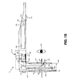
- Figure 1B depicts a top view of a portion of head mounted display device 2, including a portion of a frame 115 that includes temple 102 and nose bridge 104.
- Frame 115 provides a support for holding elements of the system in place as well as a conduit for electrical connections. Only the right side of head mounted display device 2 is depicted.
- a microphone 110 for recording sounds and transmitting that audio data to processing unit 4, as described below.
- At the front of head mounted display device 2 is physical environment facing video camera 113 that can capture video and still images. Those images are transmitted to processing unit 4, as described below.
- frame 115 In order to show the components of head mounted display device 2, a portion of the frame 115 is shown in dotted lines to expose the see-through lenses 116, 118 and 119 arranged therein and the elements 139a, 139b, 139c of a focal region adjustment unit 139 for the variable focus lens 119.
- Support element 139c may be made of a see-through material like glass or plastic.
- frame 115 provides a convenient eyeglass frame as support for the elements of the system discussed further below.
- other support structures can be used. An example of such a structure is a visor.
- Lens 119 is a variable focus lens.
- An example of a variable focus lens is a liquid lens.
- the lens includes a flexible surface 117 which can change its shape. For example it may be made more convex, made straight, or more concave.
- see-through lenses 116 and 118 provide protection from factors in the physical environment like dust and being dropped to the liquid filled variable lens.
- Lens 116 and 118 may be standard lenses used in eye glasses and either or both may include a prescription.
- the see-through device may include just one other standard lens or only the variable focus lens 119 likely enclosed within the frame 115 by glass or plastic as protection from environmental factors such as dust and falls.
- lens 119 may be made of a clear film such as a version of Mylar®, and the liquid may be a silicone oil such as Dow-Corning DC-703 or DC-705.
- a microdisplay assembly 173 comprises light processing elements and a variable focus adjuster 135.
- An example of light processing element is a microdisplay unit 120.
- Other examples include one or more optical elements such as one or more lenses of a lens system 122 and one or more reflecting elements such as surfaces 124a and 124b.
- Lens system 122 may comprise a single lens or a plurality of lenses.
- the microdisplay unit 120 includes an image source and generates an image of a virtual object.
- the microdisplay unit 120 is optically aligned with the lens system 122 and the reflecting surfaces 124a and 124b.
- the optical alignment may be along an optical axis 133 or an optical path 133 including one or more optical axes.
- the microdisplay unit 120 projects the image of the virtual object through lens system 122, which may direct the image light, onto reflecting element 124a (e.g. a mirror or other surface) which directs the light of the virtual image to a partially reflecting element 124b which combines the virtual image view 143 with the natural or actual and direct view 142.
- the combination of views are directed into a user's eye 140.
- the variable focus adjuster 135 changes the displacement between one or more light processing elements in the optical path of the microdisplay assembly or an optical power of an element in the microdisplay assembly.
- the optical power of a lens is defined as the reciprocal of its focal length, e.g. 1/focal length, so a change in one effects the other. The change results in a change in the region of the field of view which is in focus for an image generated by the microdisplay assembly 173.
- the displacement changes are guided within an armature 137 supporting at least one light processing element such as the lens system 122 and the microdisplay 120 in this example.
- the armature 137 helps stabilize the alignment along the optical path 133 during physical movement of the elements to achieve a selected displacement or optical power.
- the adjuster 135 may move one or more optical elements such as a lens in lens system 122 within the armature 137.
- the armature may have grooves or space in the area around a light processing element so it slides over the element, for example, microdisplay 120, without moving the light processing element.
- the displacement range is typically on the order of a few millimeters (mm). In one example, the range is 1-2 mm. In other examples, the armature 137 may provide support to the lens system 122 for focal adjustment techniques involving adjustment of other physical parameters than displacement as discussed in the examples of Figures 2A through 2D below.
- the adjuster 135 may be an actuator such as a piezoelectric motor.
- Other technologies for the actuator may also be used and some examples of such technologies are a voice coil formed of a coil and a permanent magnet, a magnetostriction element, and an electrostriction element.
- microdisplay 120 can be implemented using a transmissive projection technology where the light source is modulated by optically active material, backlit with white light. These technologies are usually implemented using LCD type displays with powerful backlights and high optical energy densities.
- Microdisplay 120 can also be implemented using a reflective technology for which external light is reflected and modulated by an optically active material. The illumination is forward lit by either a white source or RGB source, depending on the technology.
- Digital light processing (DLP), liquid crystal on silicon (LCOS) and Mirasol ® display technology from Qualcomm, Inc. are all examples of reflective technologies which are efficient as most energy is reflected away from the modulated structure and may be used in the system described herein.
- microdisplay 120 can be implemented using an emissive technology where light is generated by the display.
- a PicoPTM engine from Microvision, Inc. emits a laser signal with a micro mirror steering either onto a tiny screen that acts as a transmissive element or beamed directly into the eye (e.g., laser).
- Head mounted display device 2 also includes a system for tracking the position of the user's eyes. As will be explained below, the system will track the user's position and orientation so that the system can determine the field of view of the user. However, a human will not perceive everything in front of them. Instead, a user's eyes will be directed at a subset of the environment. Therefore, in one embodiment, the system will include technology for tracking the position of the user's eyes in order to refine the measurement of the field of view of the user.
- head mounted display device 2 includes eye tracking assembly 134 (see Figure 1 B) , which will include an eye tracking illumination device 134A and eye tracking camera 134B (see Figure 3 ).
- eye tracking illumination source 134A includes one or more infrared (IR) emitters, which emit IR light toward the eye.
- Eye tracking camera 134B includes one or more cameras that sense the reflected IR light.
- the position of the pupil can be identified by known imaging techniques which detect the reflection of the cornea. For example, see U.S. patent 7,401,920 , entitled “Head Mounted Eye Tracking and Display System", issued July 22, 2008 to Kranz et al.. Such a technique can locate a position of the center of the eye relative to the tracking camera.
- eye tracking involves obtaining an image of the eye and using computer vision techniques to determine the location of the pupil within the eye socket In one embodiment, it is sufficient to track the location of one eye since the eye usually moves in unison. However, it is possible to track each eye separately.
- the system will use four infrared (IR) LEDs and four IR photo detectors in rectangular arrangement so that there is one IR LED and IR photo detector at each corner of the lens of head mounted display device 2.
- IR infrared
- Light from the LEDs reflect off the eyes.
- the amount of infrared light detected at each of the four IR photo detectors determines the pupil direction. That is, the amount of white versus black in the eye will determine the amount of light reflected off the eye for that particular photo detector.
- the photo detector will have a measure of the amount of white or black in the eye. From the four samples, the system can determine the direction of the eye.
- Figure 1 B shows one assembly with one IR emitter
- the structure of Figure 1B can be adjusted to have four IR transmitters and/or four IR sensors. More or less than four IR transmitters and/or four IR sensors can also be used.
- Another embodiment for tracking the direction of the eyes is based on charge tracking. This concept is based on the observation that a retina carries a measurable positive charge and the cornea has a negative charge. Sensors are mounted by the user's ears (near earphones 130) to detect the electrical potential while the eyes move around and effectively read out what the eyes are doing in real time. Other embodiments for tracking eyes can also be used.
- Control circuits 136 provide various electronics that support the other components of head mounted display device 2. More details of control circuits 136 are provided below with respect to Figure 3 .
- ear phones 130 Inside, or mounted to temple 102, are ear phones 130, inertial sensors 132 and temperature sensor 138.
- inertial sensors 132 include a three axis magnetometer 132A, three axis gyro 132B and three axis accelerometer 132C (See Figure 3 ). The inertial sensors are for sensing position, orientation, sudden accelerations of head mounted display device 2.
- Figure 1B only shows half of the head mounted display device 2.
- a full head mounted display device would include another set of see through lenses 116 and 118, another variable focus lens 119, another micro display 120, another lens system 122, room facing camera 113, eye tracking assembly 134, earphones 130, and temperature sensor 138.
- Figure 1C is a top view of a portion of another embodiment of a head mounted display device comprising a variable focus lens positioned to be seen through by a user.
- variable focus lens 119 is a liquid lens.
- a reflecting element 124 guides the image into a lightguide optical element 112.
- Lightguide optical element 112 transmits light from microdisplay 120 to the eye 140 of the user wearing head mounted display device 2.
- Lightguide optical element 112 also allows light from in front of the head mounted display device 2 to be transmitted through lightguide optical element 112 to eye 140, as depicted by arrow 142, thereby allowing the user to have an actual direct view of the space in front of head mounted display device 2 in addition to receiving a virtual image from microdisplay 120.
- the walls of lightguide optical element 112 are see-through.
- Lightguide optical element 112 includes the reflecting surface 124.
- Light from microdisplay 120 passes through lens system 122 and becomes incident on reflecting surface 124.
- the reflecting surface 124 reflects the incident light from the microdisplay 120 such that light is trapped inside a planar, substrate comprising lightguide optical element 112 by internal reflection. After several reflections off the surfaces of the substrate, the trapped light waves reach an array of selectively reflecting surfaces 126. Note that only one of the five surfaces is labeled 126 to prevent over-crowding of the drawing. Reflecting surfaces 126 couple the light waves incident upon those reflecting surfaces out of the substrate into the eye 140 of the user. As different light rays will travel and bounce off the inside of the substrate at different angles, the different rays will hit the various reflecting surfaces 126 at different angles.
- each eye will have its own lightguide optical element 112.
- each eye can have its own microdisplay 120 that can display the same image in both eyes or different images in the two eyes.
- lens 119 has a flexible membrane 117a, 117b on both sides.
- the focal region adjustment units 139a, 139b may have reservoirs and may be used as pumps to fill and remove liquid from the lens 119.
- Figure 1C only shows half of the head mounted display device 2.
- a full head mounted display device would include another variable focus lens 119, another lightguide optical element 112, another micro display 120, another lens system 122, room facing camera 113, eye tracking assembly 134, earphones 130, and temperature sensor 138.
- FIGS 2A through 2D illustrate different embodiments of microdisplay assemblies.
- a discussion of changing focal distance is provided.
- the configuration of the light processing elements of the microdisplay assembly 173 create a focal distance or focal region in which a virtual object appears in an image. Changing the configuration changes the focal region for the virtual object image.
- the symbol f represents the focal length of a lens such as lens system 122 in the microdisplay assembly 173.
- the lens system 122 has a front nodal point and a rear nodal point. If light rays are directed toward either nodal point at a given angle relative to the optical axis, the light rays will emerge from the other nodal point at an equivalent angle relative to the optical axis.
- the rear nodal point of lens system 122 would be between itself and the microdisplay 120 in Figure 1C or in Figure 1B .
- the distance from the rear nodal point to the microdisplay 120 may be denoted as S 2 .
- the front nodal point is typically within a few mm of lens system 122.
- the target location is the location of the virtual image to be generated by the microdisplay 120 in a three-dimensional model of the user's physical space. (See discussion of Figures 9-11A below for more details about creating the model.)
- the distance from the front nodal point to the target location of the virtual image may be denoted as S 1 . Since the image is to be a virtual image appearing on the same side of the lens as the microdisplay 120, sign conventions give that S 1 has a negative value.
- S 1 and S 2 are varied to focus virtual objects at different depths.
- an initial position may have S 1 set to infinity, and S 2 equal to the focal length of lens system 122.
- S 1 is now about -300mm
- f is 10mm
- S 2 is set currently at the initial position of the focal length, 10mm, meaning the rear nodal point of lens system 122 is 10 mm from the microdisplay 120.
- the processing unit 4 can calculate the displacement values for S1 and S2, leaving the focal length f fixed and cause the control circuitry 136 to cause a variable adjuster driver 237 (see Figure 3 ) to send drive signals to have the variable virtual focus adjuster 135 move the lens system 122 along the optical path 133 for example.
- the microdisplay unit 120 may be moved instead or in addition to moving the lens system 122.
- the focal length of at least one lens in the lens system 122 may be changed instead or with changes in the displacement along the optical path 133 as well.
- Some embodiments of microdisplay assemblies are illustrated in Figures 2A through 2D .
- the specific number of lenses shown are just examples. Other numbers and configurations of lenses operating on the same principles may be used.
- the discussion of the adjustable liquid lens is applicable to both such a lens used in the microdisplay assembly for placing virtual objects in focus and as a see-through variable focus lens for bringing real objects in focus in an augmented reality display.
- Figure 2A is an example of a rotatable lens system for use as part of a microdisplay assembly of a near-eye display.
- Each of the lenses 122a through 122d has a different focal length and are supported within a disk support 160 rotable by the variable virtual focus adjuster 135.
- the processing unit 4 determines a focal region and selects one of the focal length lenses to obtain that focal region.
- a variable adjuster driver 237 of the control circuitry 136 sends at least one control signal to the variable virtual focus adjuster 135 to rotate the disk so the selected lens is aligned in the optical path 133 of the assembly.
- Figure 2B1 and Figure 2B2 are examples of a liquid lens 158 exhibiting different radii of curvature as shown in Hongwen et al., Tunable-focus liquid lens controlled using a servo motor, OPTICS EXPRESS, 4 September 2006, Vol. 14, No. 18, pp. 8031-8036 .
- the liquid lens can be used as part of a microdisplay assembly or a see-through display lens.
- the focal length of the lens may be changed by changing the radius of curvature.
- the refractive index of the liquid or liquid of the lens is nliquid.
- This embodiment comprises a support 157, for example a sealing ring having a flexible external membrane 152, in one example a rubber membrane, as a portion or connected to it.
- the external membrane 152 is in contact with a reservoir of liquid 156.
- a lens membrane 150 rests on top of or forms a flexible side of a liquid lens 158 which can receive from and release liquid into the reservoir 156 through a channel 159.
- the flexible lens membrane 150 is an elastic membrane such as polydimethylsiloxane (PDMS) elastomeric membrane.
- PDMS polydimethylsiloxane
- Glass plate 154 behind the liquid cell provides support.
- the armature 137 may provide the support structure 157 with or without the glass plate 154 as well as a flexible membrane portion 152 for the variable virtual focus adjuster 135 as controlled by control circuitry 136 to push against as shown in Figure 2B2 and release (see Figure 2B1 ).
- support element 139c is analogous to support structure 157 with or without the glass plate 154.
- Each of the side supports 139a, 139b are analogous to the side walls 157.
- One or both of the side supports 139a, 139b may include a reservoir 156 and a flexible external membrane 152 which can be pushed and released against the reservoir 156 under the control of a driver of the control circuitry 136.
- the channel 159 can be open and closed to adjust the volume of the liquid.
- pumps may be used instead of the flexible external membrane 152.
- Figures 2B1 and 2B2 provide examples of adjusting the optical power of a variable focus liquid lens by mechanical adjustment.
- Other ways of adjusting the liquid lens may also be used.
- electro-wetting may also be used to change the optical power of a liquid lens. See US2008/0117289 Schowengerdt et al . entitled Variable Fixation Viewing Distance Scanned Light Displays.
- Figure 2B3 is another example of a focal region adjustment unit which may be used for a liquid lens as part of a microdisplay assembly or as a see-through variable focus lens.
- the lens 158 is arranged like variable focus lens 119 in Figure 1C in which both sides of the lens have flexible membranes 150a and 150b like 117a and 117b.
- the focal region adjustment units 139a and 139b can each include a support 157a, 157b, a reservoir 156a, 156b, a channel 159a, 159b and an external flexible membrane 152a, 152b which an actuator or motor such as a piezo-electric actuator or motor can push and release under the control of a focal region unit driver 239.
- the channels 159a and 159b may also be opened and closed and work with pumps to control the liquid volume in the lens 119.
- Figure 2C is an example of a birefringent lens system for use as part of a microdisplay assembly of a near-eye display.
- a birefringent material is anisotropic or directionally dependent. Describing light as a ray as an illustrative construct, a birefringent lens decomposes light into an ordinary ray and an extraordinary ray. For a single axis of anisotropy or optical axis, different refractive indices, and therefore different focal lengths, can exist for different polarizations, one parallel and one perpendicular to the axis.
- lenses 122a and 122b are lenses made of a birefringent material with different polarizations as indicated by the arrows.
- four different refractive indices or focal lengths can be predetermined for selection.
- Each different focal length can be associated with a different focal region for selection by the processing unit 4.
- the polarization combinations can be perpendicular polarizations for lenses 122a and 122b as shown in Figure 2C , the opposite perpendicular polarizations to those shown in Figure 2C , the two lenses having the same polarizations in one direction, and the two lenses have the same polarizations in the other direction of polarization.
- the variable virtual focus adjuster may apply a voltage to each lens to effect a selected polarization in one embodiment.
- a physical stress may be applied to change the polarization of a lens.
- Figure 2D is an example of an insertable lens system for use as part of a microdisplay assembly.
- each of a number of lenses 122 is attached to a respective arm 123 attached to the armature 137.
- Each arm 123 moves its one or more optical elements 122, for example a lens or lens system 122, in position at a displacement in the optical path 133 of the microdisplay assembly under the control of the variable virtual focus adjuster 135.
- each lens 122 can be set a certain distance apart from its neighbors, for example 0.1 millimeters (mm) apart.
- Non-uniform spacing and adjustable displacements can also be used.
- the focal length of each inserted element can be chosen to affect the desired virtual image distance.
- displacement along the optical path 133 may also be performed.
- the processing of the microdisplay assembly and the focal region adjustment unit may be performed for each eye for the perspective of the respective eye so the virtual image appears in the user's current focal region, e.g. the Panum's fusional area, the area of single vision for humans.
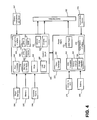
- Figure 3 is a block diagram depicting the various components of head mounted display device 2.
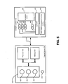
- Figure 4 is a block diagram describing the various components of processing unit 4.
- Head mounted display device 2 the components of which are depicted in Figure 3 , are used to provide a virtual image in-focus with the user's view of the real world. Additionally, the head mounted display device components of Figure 3 include many sensors that track various conditions. Head mounted display device 2 will receive instructions about the virtual image from processing unit 4 and will provide the sensor information back to processing unit 4.
- Processing unit 4, the components of which are depicted in Figure 4 will receive the sensory information from head mounted display device 2 and also from hub computing device 12 (See Figure 1 ). Based on that information, processing unit 4 will determine where and when to provide an in-focus virtual image to the user and send instructions accordingly to the head mounted display device of Figure 3 .
- Figure 3 shows the control circuit 200 in communication with the power management circuit 202.
- Control circuit 200 includes processor 210, memory controller 212 in communication with memory 214 (e.g., D-RAM), camera interface 216, camera buffer 218, display driver 220, display formatter 222, timing generator 226, display out interface 228, and display in interface 230.
- memory 214 e.g., D-RAM
- control circuit 220 all of components of control circuit 220 are in communication with each other via dedicated lines of one or more buses. In another embodiment, each of the components of control circuit 200 are in communication with processor 210.
- Camera interface 216 provides an interface to the two physical environment facing cameras 113 and stores images received from the physical environment facing cameras in camera buffer 218.
- Display driver 220 will drive microdisplay 120.
- Display formatter 222 may provide information, about the virtual image being displayed on microdisplay 120 to one or more processors of one or more computer systems, e.g. 4, 12, 210 performing processing for the augmented reality system.
- Timing generator 226 is used to provide timing data for the system.
- Display out 228 is a buffer for providing images from physical environment facing cameras 113 to the processing unit 4.
- Display in 230 is a buffer for receiving images such as a virtual image to be displayed on microdisplay 120.
- Display out 228 and display in 230 communicate with band interface 232 which is an interface to processing unit 4.
- Power management circuit 202 includes voltage regulator 234, eye tracking illumination driver 236, variable adjuster driver 237, focal region unit driver 239, audio DAC and amplifier 238, microphone preamplifier and audio ADC 240, temperature sensor interface 242 and clock generator 244.
- Voltage regulator 234 receives power from processing unit 4 via band interface 232 and provides that power to the other components of head mounted display device 2.
- Eye tracking illumination driver 236 provides the IR lightsource for eye tracking illumination 134A, as described above.
- Audio DAC and amplifier 238 receives the audio information from earphones 130.
- Microphone preamplifier and audio ADC 240 provides an interface for microphone 110.
- Temperature sensor interface 242 is an interface for temperature sensor 138.
- Power management unit 202 also provides power and receives data back from three axis magnetometer 132A, three axis gyro 132B and three axis accelerometer 132C.
- the variable adjuster driver 237 provides a control signal, for example a drive current or a drive voltage, to the adjuster 135 to move one or more elements of the microdisplay assembly to achieve a displacement for a focal region calculated by software executing in the processing unit 4 or the hub computer 12 or both.
- a control signal for example a drive current or a drive voltage
- the variable adjuster driver 237 receives timing signals from the timing generator 226, or alternatively, the clock generator 244 to operate at a programmed rate or frequency.
- the focal region unit driver 239 provides a control signal, for example, a driver current or a drive voltage to the focal region adjustment unit 139, in a mechanical adjustment example, to move one or more elements of the unit 139 to change the optical power of the variable focus lens 119 based on an adjustment value calculated by software executing in the processing unit 4 or the hub computer 12 or both.
- a flexible membrane 152 of one of the side supports 139a, 139b including the reservoir 156 and channel 159 to the liquid in the lens 119 may be pushed or released by an actuator such as a piezo-electric actuator responding to the drive signal from the focal region unit driver 239.
- Control circuit 304 includes a central processing unit (CPU) 320, graphics processing unit (GPU) 322, cache 324, RAM 326, memory control 328 in communication with memory 330 (e.g., D-RAM), flash memory controller 332 in communication with flash memory 334 (or other type of non-volatile storage), display out buffer 336 in communication with head mounted display device 2 via band interface 302 and band interface 232, display in buffer 338 in communication with head mounted display device 2 via band interface 302 and band interface 232, microphone interface 340 in communication with an external microphone connector 342 for connecting to a microphone, PCI express interface for connecting to a wireless communication device 346, and USB port(s) 348.
- CPU central processing unit
- GPU graphics processing unit
- RAM random access memory
- memory control 328 in communication with memory 330 (e.g., D-RAM)
- flash memory controller 332 in communication with flash memory 334 (or other type of non-volatile storage)
- display out buffer 336 in communication with head mounted display device 2 via band interface
- wireless communication component 346 can include a Wi-Fi enabled communication device, Bluetooth communication device, infrared communication device, etc.
- the USB port can be used to dock the processing unit 4 to hub computing device 12 in order to load data or software onto processing unit 4, as well as charge processing unit 4.
- CPU 320 and GPU 322 are the main workhorses for determining where, when and how to insert virtual images into the view of the user. More details are provided below.
- Power management circuit 306 includes clock generator 360, analog to digital converter 362, battery charger 364, voltage regulator 366, head mounted display power source 376, and temperature sensor interface 372 in communication with temperature sensor 374 (located on the wrist band of processing unit 4).
- An alternating current to direct current converter 362 is connected to a charging jack 370 for receiving an AC supply and creating a DC supply for the system.
- Voltage regulator 366 is in communication with battery 368 for supplying power to the system.
- Battery charger 364 is used to charge battery 368 (via voltage regulator 366) upon receiving power from charging jack 370.
- HMD power interface 376 provides power to the head mounted display device 2.
- the above-described system will be configured to insert a virtual image into the field of view of a user so that the virtual image appears naturally in-focus or out-of-focus to the user.
- the virtual image will be adjusted to match the appropriate orientation, size and shape based on the environment for which the image is being inserted into.
- head mounted display device 2, processing unit 4 and hub computing device 12 work together as each of the devices includes a subset of sensors that are used to obtain the data for determining where, when and how to insert the virtual images.
- the calculations that determine where, how and when to insert a virtual image are performed by the hub computing device 12. In another embodiment, those calculations are performed by processing unit 4. In another embodiment some of the calculations are performed by hub computing device 12 while other calculations are performed by processing unit 4. In other embodiments, the calculations can be performed by head mounted display device 2.
- hub computing device 12 will create a model of the environment that the user is in and track various moving objects in that environment.
- hub computing device 12 tracks the field of view of the head mounted display device 2 by tracking the position and orientation of head mounted display device 2.
- the model and the tracking information is provided from hub computing device 12 to processing unit 4.
- Sensor information obtained by head mounted display device 2 is transmitted to processing unit 4.
- Processing unit 4 uses additional sensor information it receives from head mounted display device 2 to refine the field of view of the user and provide instructions to head mounted display device 2 on how, where and when to insert the virtual image.
- Figure 5 illustrates an example embodiment of hub computing system 12 with a capture device.
- capture devices 20A and 20B are the same structure, therefore, Figure 5 only shows capture device 20A.
- capture device 20A may be configured to capture video with depth information including a depth image that may include depth values via any suitable technique including, for example, time-of-flight, structured light, stereo image, or the like.
- the capture device 20A may organize the depth information into "Z layers," or layers that may be perpendicular to a Z axis extending from the depth camera along its line of sight.
- capture device 20A may include a camera component 423.
- camera component 423 may be or may include a depth camera that may capture a depth image of a scene.
- the depth image may include a two-dimensional (2-D) pixel area of the captured scene where each pixel in the 2-D pixel area may represent a depth value such as a distance in, for example, centimeters, millimeters, or the like of an object in the captured scene from the camera.
- Camera component 23 may include an infra-red (IR) light component 425, a three-dimensional (3-D) camera 426, and an RGB (visual image) camera 428 that may be used to capture the depth image of a scene.
- IR infra-red
- 3-D three-dimensional
- RGB visual image
- the IR light component 425 of the capture device 20A may emit an infrared light onto the scene and may then use sensors (in some embodiments, including sensors not shown) to detect the backscattered light from the surface of one or more targets and objects in the scene using, for example, the 3-D camera 426 and/or the RGB camera 428.
- pulsed infrared light may be used such that the time between an outgoing light pulse and a corresponding incoming light pulse may be measured and used to determine a physical distance from the capture device 20A to a particular location on the targets or objects in the scene. Additionally, in other example embodiments, the phase of the outgoing light wave may be compared to the phase of the incoming light wave to determine a phase shift. The phase shift may then be used to determine a physical distance from the capture device to a particular location on the targets or objects.
- time-of-flight analysis may be used to indirectly determine a physical distance from the capture device 20A to a particular location on the targets or objects by analyzing the intensity of the reflected beam of light over time via various techniques including, for example, shuttered light pulse imaging.
- capture device 20A may use a structured light to capture depth information.
- patterned light i.e., light displayed as a known pattern such as grid pattern, a stripe pattern, or different pattern
- the pattern may become deformed in response.
- Such a deformation of the pattern may be captured by, for example, the 3-D camera 426 and/or the RGB camera 428 (and/or other sensor) and may then be analyzed to determine a physical distance from the capture device to a particular location on the targets or objects.
- the IR Light component 425 is displaced from the cameras 425 and 426 so triangulation can be used to determined distance from cameras 425 and 426.
- the capture device 20A will include a dedicated IR sensor to sense the IR light, or a sensor with an IR filter.
- the capture device 20A may include two or more physically separated cameras that may view a scene from different angles to obtain visual stereo data that may be resolved to generate depth information.
- Other types of depth image sensors can also be used to create a depth image.
- the capture device 20A may further include a microphone 430, which includes a transducer or sensor that may receive and convert sound into an electrical signal. Microphone 430 may be used to receive audio signals that may also be provided by to hub computing system 12.
- the capture device 20A may further include a processor 432 that may be in communication with the image camera component 423.
- Processor 432 may include a standardized processor, a specialized processor, a microprocessor, or the like that may execute instructions including, for example, instructions for receiving a depth image, generating the appropriate data format (e.g., frame) and transmitting the data to hub computing system 12.
- Capture device 20A may further include a memory 434 that may store the instructions that are executed by processor 432, images or frames of images captured by the 3-D camera and/or RGB camera, or any other suitable information, images, or the like.
- memory 434 may include random access memory (RAM), read only memory (ROM), cache, flash memory, a hard disk, or any other suitable storage component.
- RAM random access memory
- ROM read only memory
- cache flash memory
- hard disk or any other suitable storage component.
- memory 434 may be a separate component in communication with the image capture component 423 and processor 432.
- the memory 434 may be integrated into processor 432 and/or the image capture component 422.
- Capture devices 20A and 20B are in communication with hub computing system 12 via a communication link 436.
- the communication link 436 may be a wired connection including, for example, a USB connection, a Firewire connection, an Ethernet cable connection, or the like and/or a wireless connection such as a wireless 802.11 b, g, a, or n connection.
- hub computing system 12 may provide a clock to capture device 20A that may be used to determine when to capture, for example, a scene via the communication link 436.
- the capture device 20A provides the depth information and visual (e.g., RGB) images captured by, for example, the 3-D camera 426 and/or the RGB camera 428 to hub computing system 12 via the communication link 436.
- RGB depth information and visual
- the depth images and visual images are transmitted at 30 frames per second; however, other frame rates can be used.
- Hub computing system 12 may then create and use a model, depth information, and captured images to, for example, control an application such as a game or word processor and/or animate an avatar or on-screen character.
- Hub computing system 12 includes depth image processing and skeletal tracking module 450, which uses the depth images to track one or more persons detectable by the depth camera function of capture device 20A.
- Depth image processing and skeletal tracking module 450 provides the tracking information to application 452, which can be a video game, productivity application, communications application or other software application etc.
- the audio data and visual image data is also provided to application 452 and depth image processing and skeletal tracking module 450.
- Application 452 provides the tracking information, audio data and visual image data to recognizer engine 454.
- recognizer engine 454 receives the tracking information directly from depth image processing and skeletal tracking module 450 and receives the audio data and visual image data directly from capture devices 20A and 20B.
- Recognizer engine 454 is associated with a collection of filters 460, 462, 464,..., 466 each comprising information concerning a gesture, action or condition that may be performed by any person or object detectable by capture device 20A or 20B.
- the data from capture device 20A may be processed by filters 460, 462, 464, ..., 466 to identify when a user or group of users has performed one or more gestures or other actions.
- Those gestures may be associated with various controls, objects or conditions of application 452.
- hub computing system 12 may use the recognizer engine 454, with the filters, to interpret and track movement of objects (including people).
- Capture devices 20A and 20B provide RGB images (or visual images in other formats or color spaces) and depth images to hub computing system 12.
- the depth image may be a plurality of observed pixels where each observed pixel has an observed depth value.
- the depth image may include a two-dimensional (2-D) pixel area of the captured scene where each pixel in the 2-D pixel area may have a depth value such as distance of an object in the captured scene from the capture device.
- Hub computing system 12 will use the RGB images and depth images to track a user's or object's movements. For example, the system will track a skeleton of a person using the depth images. There are many methods that can be used to track the skeleton of a person using depth images.
- U.S. Patent Application 12/475,308 "Device for identifying and Tracking Multiple Humans Over Time,” filed on May 29, 2009
- U.S. Patent Application 12/696,282 “Visual Based Identity Tracking,” filed on January 29, 2010
- U.S. Patent Application 12/641,788 “Motion Detection Using Depth Images” filed on December 18, 2009
- U.S. Patent Application 12/575,388 “Human Tracking System,” filed on October 7, 2009.
- Recognizer engine 454 includes multiple filters 460, 462, 464, ..., 466 to determine a gesture or action.
- a filter comprises information defining a gesture, action or condition along with parameters, or metadata, for that gesture, action or condition. For instance, a throw, which comprises motion of one of the hands from behind the rear of the body to past the front of the body, may be implemented as a gesture comprising information representing the movement of one of the hands of the user from behind the rear of the body to past the front of the body, as that movement would be captured by the depth camera. Parameters may then be set for that gesture.
- a parameter may be a threshold velocity that the hand has to reach, a distance the hand travels (either absolute, or relative to the size of the user as a whole), and a confidence rating by the recognizer engine that the gesture occurred.
- These parameters for the gesture may vary between applications, between contexts of a single application, or within one context of one application over time.
- Filters may be modular or interchangeable.
- a filter has a number of inputs (each of those inputs having a type) and a number of outputs (each of those outputs having a type).
- a first filter may be replaced with a second filter that has the same number and types of inputs and outputs as the first filter without altering any other aspect of the recognizer engine architecture. For instance, there may be a first filter for driving that takes as input skeletal data and outputs a confidence that the gesture associated with the filter is occurring and an angle of steering.
- a filter need not have a parameter. For instance, a "user height" filter that returns the user's height may not allow for any parameters that may be tuned.
- An alternate "user height” filter may have tunable parameters - such as to whether to account for a user's footwear, hairstyle, headwear and posture in determining the user's height.
- Inputs to a filter may comprise things such as joint data about a user's joint position, angles formed by the bones that meet at the joint, RGB color data from the scene, and the rate of change of an aspect of the user.
- Outputs from a filter may comprise things such as the confidence that a given gesture is being made, the speed at which a gesture motion is made, and a time at which a gesture motion is made.
- Recognizer engine 454 may have a base recognizer engine that provides functionality to the filters.
- the functionality that recognizer engine 454 implements includes an input-over-time archive that tracks recognized gestures and other input, a Hidden Markov Model implementation (where the modeled system is assumed to be a Markov process - one where a present state encapsulates any past state information used to determine a future state, so no other past state information must be maintained for this purpose-with unknown parameters, and hidden parameters are determined from the observable data), as well as other functionality for solving particular instances of gesture recognition.
- Filters 460, 462, 464, ..., 466 are loaded and implemented on top of the recognizer engine 454 and can utilize services provided by recognizer engine 454 to all filters 460, 462, 464, ..., 466.
- recognizer engine 454 receives data to determine whether it meets the requirements of any filter 460, 462, 464, ..., 466. Since these provided services, such as parsing the input, are provided once by recognizer engine 454 rather than by each filter 460, 462, 464, ..., 466, such a service need only be processed once in a period of time as opposed to once per filter for that period, so the processing used to determine gestures is reduced.
- Application 452 may use the filters 460, 462, 464, ..., 466 provided with the recognizer engine 454, or it may provide its own filter, which plugs in to recognizer engine 454.
- all filters have a common interface to enable this plug-in characteristic. Further, all filters may utilize parameters, so a single gesture tool below may be used to debug and tune the entire filter system.
- recognizer engine 454 More information about recognizer engine 454 can be found in U.S. Patent Application 12/422,661 , "Gesture Recognizer System Architecture,” filed on April 13, 2009. More information about recognizing gestures can be found in U.S. Patent Application 12/391,150 , “Standard Gestures,” filed on February 23,2009; and U.S. Patent Application 12/474,655 , “Gesture Tool” filed on May 29, 2009.
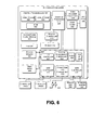
- FIG. 6 illustrates an example embodiment of a computing system that may be used to implement hub computing system 12.
- the multimedia console 500 has a central processing unit (CPU) 501 having a level 1 cache 502, a level 2 cache 504, and a flash ROM (Read Only Memory) 506.
- the level 1 cache 502 and a level 2 cache 504 temporarily store data and hence reduce the number of memory access cycles, thereby improving processing speed and throughput.
- CPU 501 may be provided having more than one core, and thus, additional level 1 and level 2 caches 502 and 504.
- the flash ROM 506 may store executable code that is loaded during an initial phase of a boot process when the multimedia console 500 is powered on.
- a graphics processing unit (GPU) 508 and a video encoder/video codec (coder/decoder) 514 form a video processing pipeline for high speed and high resolution graphics processing. Data is carried from the graphics processing unit 508 to the video encoder/video codec 514 via a bus. The video processing pipeline outputs data to an AN (audio/video) port 540 for transmission to a television or other display.
- a memory controller 510 is connected to the GPU 508 to facilitate processor access to various types of memory 512, such as, but not limited to, a RAM (Random Access Memory).
- the multimedia console 500 includes an I/O controller 520, a system management controller 522, an audio processing unit 523, a network interface controller 524, a first USB host controller 526, a second USB controller 528 and a front panel I/O subassembly 530 that are preferably implemented on a module 518.
- the USB controllers 526 and 528 serve as hosts for peripheral controllers 542(1)-542(2), a wireless adapter 548, and an external memory device 546 (e.g., flash memory, external CD/DVD ROM drive, removable media, etc.).
- the network interface 524 and/or wireless adapter 548 provide access to a network (e.g., the Internet, home network, etc.) and may be any of a wide variety of various wired or wireless adapter components including an Ethernet card, a modem, a Bluetooth module, a cable modem, and the like.
- a network e.g., the Internet, home network, etc.
- wired or wireless adapter components including an Ethernet card, a modem, a Bluetooth module, a cable modem, and the like.
- System memory 543 is provided to store application data that is loaded during the boot process.
- a media drive 544 is provided and may comprise a DVD/CD drive, Blu-Ray drive, hard disk drive, or other removable media drive, etc.
- the media drive 144 may be internal or external to the multimedia console 500.
- Application data may be accessed via the media drive 544 for execution, playback, etc. by the multimedia console 500.
- the media drive 544 is connected to the I/O controller 520 via a bus, such as a Serial ATA bus or other high speed connection (e.g., IEEE 1394).
- the system management controller 522 provides a variety of service functions related to assuring availability of the multimedia console 500.
- the audio processing unit 523 and an audio codec 532 form a corresponding audio processing pipeline with high fidelity and stereo processing. Audio data is carried between the audio processing unit 523 and the audio codec 532 via a communication link.
- the audio processing pipeline outputs data to the A/V port 540 for reproduction by an external audio user or device having audio capabilities.
- the front panel I/O subassembly 530 supports the functionality of the power button 550 and the eject button 552, as well as any LEDs (light emitting diodes) or other indicators exposed on the outer surface of the multimedia console 100.
- a system power supply module 536 provides power to the components of the multimedia console 100.
- a fan 538 cools the circuitry within the multimedia console 500.
- the CPU 501, GPU 508, memory controller 510, and various other components within the multimedia console 500 are interconnected via one or more buses, including serial and parallel buses, a memory bus, a peripheral bus, and a processor or local bus using any of a variety of bus architectures.
- bus architectures can include a Peripheral Component Interconnects (PCI) bus, PCI-Express bus, etc.
- application data may be loaded from the system memory 543 into memory 512 and/or caches 502, 504 and executed on the CPU 501.
- the application may present a graphical user interface that provides a consistent user experience when navigating to different media types available on the multimedia console 500.
- applications and/or other media contained within the media drive 544 may be launched or played from the media drive 544 to provide additional functionalities to the multimedia console 500.
- the multimedia console 500 may be operated as a standalone system by simply connecting the system to a television or other display. In this standalone mode, the multimedia console 500 allows one or more users to interact with the system, watch movies, or listen to music. However, with the integration of broadband connectivity made available through the network interface 524 or the wireless adapter 548, the multimedia console 500 may further be operated as a participant in a larger network community. Additionally, multimedia console 500 can communicate with processing unit 4 via wireless adaptor 548.
- a set amount of hardware resources are reserved for system use by the multimedia console operating system. These resources may include a reservation of memory, CPU and GPU cycle, networking bandwidth, etc. Because these resources are reserved at system boot time, the reserved resources do not exist from the application's view.
- the memory reservation preferably is large enough to contain the launch kernel, concurrent system applications and drivers.
- the CPU reservation is preferably constant such that if the reserved CPU usage is not used by the system applications, an idle thread will consume any unused cycles.
- lightweight messages generated by the system applications are displayed by using a GPU interrupt to schedule code to render popup into an overlay.
- the amount of memory required for an overlay depends on the overlay area size and the overlay preferably scales with screen resolution. Where a full user interface is used by the concurrent system application, it is preferable to use a resolution independent of application resolution. A scaler may be used to set this resolution such that the need to change frequency and cause a TV resync is eliminated.
- multimedia console 500 boots and system resources are reserved, concurrent system applications execute to provide system functionalities.
- the system functionalities are encapsulated in a set of system applications that execute within the reserved system resources described above.
- the operating system kernel identifies threads that are system application threads versus gaming application threads.
- the system applications are preferably scheduled to run on the CPU 501 at predetermined times and intervals in order to provide a consistent system resource view to the application. The scheduling is to minimize cache disruption for the gaming application running on the console.
- a multimedia console application manager controls the gaming application audio level (e.g., mute, attenuate) when system applications are active.
- Optional input devices are shared by gaming applications and system applications.
- the input devices are not reserved resources, but are to be switched between system applications and the gaming application such that each will have a focus of the device.
- the application manager preferably controls the switching of input stream, without knowing the gaming application's knowledge and a driver maintains state information regarding focus switches.
- Capture devices 20A and 20B may define additional input devices for the console 500 via USB controller 526 or other interface.
- hub computing system 12 can be implemented using other hardware architectures. No one hardware architecture is required.
- the example computer systems illustrated in Figures 3 , 4 , 5 and 6 include examples of computer readable storage media. Such media may include volatile and nonvolatile, removable and non-removable media implemented in any method or technology for storage of information such as computer readable instructions, data structures, program modules or other data.
- Computer storage media includes, but is not limited to, RAM, ROM, EEPROM, flash memory or other memory technology, CD-ROM, digital versatile disks (DVD) or other optical disk storage, memory sticks or cards, magnetic cassettes, magnetic tape, magnetic disk storage or other magnetic storage devices, or any other medium which can be used to store the desired information and which can accessed by a computer.
- Some examples of computer readable storage media in the figures include memory 214 of Figure 3 , flash memory 334, memory 330, RAM 326 and cache 324 of Figure 4 , memory 434 of Figure 5 , and ROM 506, caches 502, 504, memory 512, system memory 543, memory unit 546 and media drive 544 of Figure 6 .
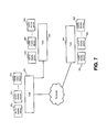
- Figure 1A depicts one head mounted display device 2 and processing unit 4 (collectively referred to as a mobile display device) in communication with one hub computing device 12 (referred to as a hub).
- a mobile display device in communication with one hub computing device 12 (referred to as a hub).
- multiple mobile display devices can be in communication with a single hub.
- Each of the mobile display devices will communicate with the hub using wireless communication, as described above.
- it is contemplated that much of the information that is useful to all of the mobile display devices will be computed and stored at the hub and transmitted to each of the mobile display devices.
- the hub will generate the model of the environment and provide that model to all of the mobile display devices in communication with the hub.
- the hub can track the location and orientation of the mobile display devices and of the moving objects in the room, and then transfer that information to each of the mobile display devices.
- a multi-user system that can vary the focus of virtual and real content to be in focus for a user could include multiple hubs, with each hub including one or more mobile display devices.
- the hubs can communicate with each other directly or via the Internet (or other networks).
- Figure 7 shows hubs 560, 562 and 564.
- Hub 560 communicates directly to hub 562.
- Hub 560 communicates to hub 564 via the Internet.
- Hub 560 communicated with mobile display devices 570, 572, ..., 574.
- Hub 562 communicates with mobile display device 578, 580, ..., 582.
- Hub 564 communicates with mobile display device 584, 586, ..., 588.
- Each of the mobile display devices communicate with their respective hub via wireless communication as discussed above.
- each of the hubs can provide a portion of the model of the environments, or one hub can create the model for the other hubs.
- Each of the hubs will track a subset of moving objects and share that information with the other hubs, which will in turn share the information with the appropriate mobile display devices.
- Sensor information for the mobile display devices will be provided to their respective hubs and then shared to the other hubs for eventual sharing to the other mobile display devices.
- information shared between hubs can include skeleton tracking, information about the models, various states of applications, and other tracking.
- the information communicated between the hubs and their respective mobile display devices include tracking information of moving objects, the state and physics updates for the world models, geometry and texture information, video and audio, and other information used to perform the operations described herein.
- Figure 8 is a flowchart describing one embodiment of a process for focus improvement in an augmented reality display that is performed by the components discussed above.
- the system is configured.
- an application e.g., application 452 of Figure 5
- the system can configure the system to indicate that a particular virtual image (representing a virtual object) is to be inserted into the three dimensional model of the scene, at a designated location.
- an application running on hub computing system 12 will indicate that a particular virtual image (representing a virtual object) is to be inserted into the scene as part of a video game or other process.
- step 604 the system will create a volumetric model of the space for which head mounted display device 2 is located.
- hub computing device 12 will use depth images from one or more depth cameras to create a three dimensional model of the environment or space in which head mounted display device 2 is located.
- that model is segmented into one or more objects. For example, if hub computing device 12 creates a three dimensional model of a room, that room is likely to have multiple objects in it. Examples of objects that can be in a room include persons, chairs, tables, couches, etc.
- Step 606 includes determining distinct objects from each other.
- the system will identify the objects. For example, hub computing device 12 may identify that a particular object is a table and another object is a chair.
- step 610a of Figure 8 the system determines the field of view of the user based on the model of the user space. That is, the system determines what portion of the environment or space the user is looking at.
- step 610a is a collaborative effort using hub computing device 12, processing unit 4 and head mounted display device 2.
- hub computing device 12 will track the user and the head mounted display device 2 in order to provide a preliminary determination of location and orientation of head mounted display device 2.
- Sensors on the head mounted display device 2 will be used to refine the determined orientation.
- the inertial sensors 34 described above, can be used to refine the orientation of head mounted display device 2.
- the eye tracking process described above can be used to identify a subset of the initially determined field of view that corresponds to where in particular a user is looking otherwise known as the user focal region or depth focus in the field of view. More details will be described below with respect to Figures 14, 15 and 16 .
- the system determines the user's current focal region within the user's field of view.
- eye tracking processing based on data captured by the eye tracking camera 134 for each eye, can provide the current focal region of the user. For example, the convergence between the pupils with data indicating the face position of the user can be used to triangulate to a focal point on a focal curve, the Horopter, from which the focal region, the Panum's fusional area can be calculated.
- the Panum's fusion area is the area of single vision for binocular stereopsis used by human eyes.
- step 611 the focal region adjustment unit 139 under the control of the processing unit 4 via the control circuitry 136 adjusts the variable focus lens 119 positioned to be seen through for at least one eye to focus in the current user focal region. More details will be described below with respect to Figures 12A and 12B .
- the focal length of variable focus lens is automatically adjusted to focus in the current user focal region by the components of the display device 2.
- the user does not have to take actions to change the focus of the variable focus lens when the user changes where he or she is looking.
- the microdisplay assembly 173 under the control of the processing unit 4 via the control circuitry 136 will display one or more virtual objects to appear at a real world focal distance to a user in a user field of view of the user space model. That is, the system displays a virtual image in the field of view of the user at the focal depth the user is viewing while the user is looking through the head mounted display device 2.
- the virtual object can be a stationary object or a moving object.
- the processing unit 4 may alone or in cooperation with the hub computing device 12 may optionally visually enhance an object in the user field of view.
- a real object may be visually enhanced with a virtual object in the user field of view to enhance the user's perception of the object.
- An embodiment of a process for such enhancement of a real object with a virtual image is discussed further below with respect to Figure 19 .
- step 616 the user of head mounted display device 2 will interact with an application running on hub computing device 12 (or another computing device) based on the virtual object being displayed in the head mounted display device 2.
- hub computing device 12 or another computing device
- Each of the steps 604-614 will be described in more detail below. Additionally, each of these steps and those in the figures below may be performed continuously or be repeated as the user is using the near-eye display device 2 and changing his or her focal region when changing his or her viewpoint. For example, the three dimensional model is updated as discussed further below, and the user field of view and focal region are determined repeatedly as the user moves around or moves his or her eyes. The adjustments are made to keep up with the user or objects moving in the space.
- FIG. 9 is a flowchart describing one embodiment of a process for creating a three dimensional model of the space.
- the process of Figure 9 is one example implementation of step 604 of Figure 8 .
- hub computing system 12 receives one or more depth images for multiple perspectives of the space that the head mounted display device 2 is in.
- hub computing device 12 can obtain depth images from multiple depth cameras, or multiple depth images from the same camera by pointing the camera in different directions or using a depth camera with a lens that allows a full view of the space for which a model will be built.
- depth data from the various depth images are combined based on a common coordinate system. For example, if this system receives depth images from multiple cameras, the system will correlate the two images to have a common coordinate system (e.g., line up the images).
- Figure 10 is a flowchart describing one embodiment of a process for segmenting the model of the space into objects.
- the process of Figure 10 is one example implementation of step 606 of Figure 8 .
- the system will receive one or more depth images from one or more depth cameras as discussed above. Alternatively, the system can access one or more depth images that it has already received.
- the system will receive one or more visual images from the cameras described above. Alternatively, the system can access one or more visual images already received.
- hub computing system 12 will detect one or more people based on the depth images and/or visual images. For example, the system will recognize one or more skeletons.
- hub computing device 12 will detect edges within the model based on the depth images and/or the visual images.
- hub computing device 12 will use the detected edges to identify distinct objects from each other. For example, it is assumed that edges are boundaries between objects.
- the processing unit 4 may send a message to the hub computing device 12 to send edge data for a selected real object for it to generate a virtual image to visually enhance for the real object.
- the hub computing device 12 generates the virtual image with visual enhancement for the real object, and sends the virtual image to the processing unit 4 to cause the microdisplay unit 120 to display it.
- the model created using the process of Figure 9 will be updated to show which portions of the model are associated with different objects.
- Figure 11 is a flowchart describing one embodiment of a process for identifying objects.
- the process of Figure 11 is one example implementation of step 608 of Figure 8 .
- hub computing device 12 will match identified people to user identities.
- the system may have user profiles that have visual images that can be matched to the images detected of the objects.
- a user profile can describe features of the person which can be match based on the depth images or visual images.
- users may log into the system and hub computing device 12 can use the login process to identify a particular user and track that user throughout the interaction described herein.
- hub computing device 12 will access the database of shapes.
- hub computing device will match as many objects in the model to the shapes in the database.
- step 716 those shapes that are unmatched will be highlighted and displayed to the user (e.g., using monitor 16).
- hub computing device 12 will receive user input that identifies each (or a subset) of the shapes highlighted. For example, the user can use a keyboard, mouse, speech input, or other type of input to indicate what each unidentified shape is.
- step 720 the database of shapes is updated based on the user input in step 718.
- step 722 the model of the environment created in step 604, and updated in step 606, is further updated by adding metadata for each of the objects.
- the metadata identifies the object. For example the metadata may indicate that the particular object is a round shiny table, John Doe, green leather couch, etc.
- Figure 11A is a flow chart describing one embodiment of a process for updating the model created by the process of Figure 9 in response to moving objects (e.g., a moving person or other type of object).
- the system determines that an object is moving. For example, the system will continuously receive depth images. If the depth images change over time, then an object is moving. If no moving object is detected, then the system will continue to receive depth images and continue to look for moving objects.
- step 730 the system will identify the object that is moving.
- Frame differencing or any of various tracking technologies can be used to recognize the moving object and correlate the recognized object to one of the objects identified in step 608 of Fig. 8 .
- Some objects will change shape when moving. For example, a human may change shape as the human walks or runs.
- step 732 the new shape of the moving object is identified and stored.
- step 734 the model of the environment that was previously created is updated based on the new position and shape of the moving object.
- the process of Figure 11A can be performed by processing unit 4 of hub computing device 12.
- Figure 12A is a flow chart describing an embodiment of a process for adjusting a variable focus lens in the current user focal region.
- the processing unit 4 alone or in collaboration with the hub computing system 12 determines in step 750 a focal distance from the user's eye to a determined focal point in the current user focal region.
- the focal point may be determined from the eye tracking data.
- a ray can be cast from a starting point approximating the retina of each eye based on measurements of a position and angle of each eye to an end point where the rays from each eye meet. The end point may be selected as the focal point.
- the focal point may be determined from an inference process based on the user's head position, the objects of the scene and the context of the application (e.g. 452) executing. Simultaneous localization and mapping (SLAM) techniques may also be used. In other examples, one or more focal point determination techniques can be used in combination.
- SLAM Simultaneous localization and mapping
- the processing unit 4 in step 752 selects an adjustment value for the variable focus lens 119, typically for each lens for each eye, but in any case, for at least one lens 119 (e.g. monocular HMD).
- the selected adjustment value is for a focal length which approximates the determined focal distance.
- Figure 12B is a flow chart describing an embodiment of a process for adjusting a variable focus lens for a zoom capability.
- the processing unit 4 receives user input requesting a zoom level.
- the user input may be captured as audio by microphone 110 or as gestures captured by the depth cameras 20A and 20B and processed by the hub computing device 12.
- user input or commands may be determined, at least in part, via measuring the potentials on eye muscles for user input protocols based on blinking or other eye movements.
- the user input may be captured as audio by microphone 110 or as gestures captured by the depth cameras 20A and 20B and processed by the hub computing device 12.
- the processing unit 4 or the hub computing device 12 or both in collaboration in step 762 determine a focal distance based on the zoom level and the current focal region.
- an adjustment value is selected for a variable focus lens for a focal length which approximates the focal distance, and the focal region adjustment unit 139 adjusts the variable focus lens based on the selected adjustment value in step 766.
- a user may select a zoom feature.
- An example of a zoom feature is an ability to focus which is superior to normal ability such as the ability to see in-focus at 20 feet what others with normal vision can only see at 10 feet.
- normal vision may be vision of 20/20 or 6/6 with no Presbyopia.
- a zoom feature may also be to see a specific distance further or closer or a multiplier of the current focal distance.
- the types of virtual objects and their location in a user field of view is determined by the application 452 based on default parameters, user input, or a combination of both. For example, a user may have selected a real world object of a coffee table in the room where he is running the application 452 to appear as a boulder. The virtual boulder's target location will be related to the location of the coffee table in the three dimensional model.
- a virtual dolphin may be selected by a user to swim around the room. The motion of the dolphin virtually around the room may be implemented by a trajectory path of the dolphin object in which a target location for the dolphin is updated in each display frame. Even if a user stares at the boulder, the dolphin will likely come in and out of the user's focal region and field of view generally. As the user moves his or her eyes or head, the user field of view and current focal region is updating with these movements as well.
- One or more virtual objects may be located in the user focal region and user field of view at any given time.
- Figure 13 is a flowchart describing one embodiment of a process for displaying a virtual object to be in focus when viewed by a user viewing a near-eye display.
- the process of Figure 13 is one example implementation of step 612 of Figure 8 .
- the system determines whether there are any target locations of virtual objects in the user's current field of view in step 952.
- Software executing in one or more computer systems such as the hub computing device 12 or the processing unit 4 will identify the location of the target in the field of view.
- hub computing device 12 will provide the model to processing unit 4.
- processing unit 4 will use the model of the environment and knowledge of the position and orientation of the user to determine whether the target location of any virtual object is within the user's field of view.
- step 964 returns to implementing the other steps of the process embodiment such as those in Figure 8 or Figure 19 .
- step 954 software executing in the hub computer system 12, the processing unit 4 or both identifies each virtual object in the user field of view which is in the current user focal region based on its target location in the model.
- processing unit 4 will scale and orient each identified virtual object for an image to be inserted into the user's view.
- the scaling and orienting of the virtual object will be based on its target location in the user field of view.
- processing unit 4, control circuitry 136 or both share processing to place each virtual object identified as being in the current user focal region by changing the focal region of the microdisplay assembly 173.
- an artificial depth of field technique may be applied to each virtual object whose target location is within the user's field of view but outside the user's current focal region as a function of distance from the current focal region.
- An example of an artificial depth of field technique is an artificial blur technique.
- Artificial blur can be achieved by applying a depth of field shader or other a Gaussian blur filter to simulate the object being out of focus as function of distance from the focal region.
- the technique may be performed in whole or in part by software executing on the hub computer 12, the processing unit 4 or both.
- the processing unit 4 From a depth value as part of the target location of a virtual object, the focal distance of the object in the image is determined by the processing unit 4 which also determines which pixels on a display element 112 like that enclosing the lightguide optical element 112 will map to the virtual objects in an image.
- one or more weighted Gaussian blur filters are applied to cover at least two dimensions by convolving the image with a Gaussian function such that the transformations applied to pixels further from the focal point or fixation point of the image are will receive more blurring effects.
- the Gaussian blur filter acts as a low pass filter removing high frequency information.
- the microdisplay 120 displays a virtual image including each identified virtual object.
- the processing unit 4 sends instructions to display driver 220 of control circuitry 136 for display on microdisplay 120 of the virtual image including each virtual object in the user field of view.
- the lens system 122 projects the virtual image received from the microdisplay 120 onto the reflecting elements 124a and 124b and towards the user's eyes as in Figure 1C or onto the reflecting element 124 and into the lightguide optical element 112 for viewing by the user as in Figures 1B or 1D.
- the display the user is looking through in the head mounted display device e.g., the lightguide optical element 112 is divided into pixels.
- Step 962 may include determining which pixels correspond to the target location, and those pixels will display a virtual image including each identified virtual object in step 962.
- the processing steps of Figure 13 can be performed continuously during operation of the system such that the user field of view and user focal region are updated as the user moves his or her head, and the virtual objects may be displayed as naturally moving in and out of focus for the user accordingly.
- Figure 16 is a flowchart describing one embodiment of a process for determining the field of view a user, which is an example implementation of step 610a of Figure 8 , and for determining the user focal region, which is an example implementation of step 610b of Figure 8 .
- the process of Figure 16 relies on information from the hub computing device 12 and the eye tracking technology described above.
- Figure 14 is a flowchart describing one embodiment of a process performed by the hub computing system to provide tracking information used in the process of Figure 16.
- Figure 15 is a flowchart describing one embodiment of a process for tracking an eye, the results of which are used by the process of Figure 16 .
- the hub computing device 12 will track the user's position.
- hub computing device 12 will use one or more depth images and one or more visual images to track a user (e.g., using skeleton tracking).
- One or more depth images and one or more visual images can be used to determine the position of the head mounted display device 2 and the orientation of the head mounted display device 2 in step 812.
- the position and orientation of the user and the head mounted display device 2 are transmitted from the hub computing device 12 to processing unit 4.
- the position and orientation information is received at processing unit 4.
- the processing steps of Figure 14 can be performed continuously during operation of the system such that the user is continuously tracked.
- Figure 15 is a flowchart describing one embodiment for tracking an eye using the technology described above.
- the eye is illuminated.
- the eye can be illuminated using infrared light from eye tracking illumination 134A.
- the reflection from the eye is detected using one or more eye tracking cameras 134B.
- the reflection data is sent from head mounted display device 2 to processing unit 4.
- processing unit 4 will determine the position of the eye based on the reflection data, as discussed above.
- processing unit 4 will also determine the focal depth location or focal region the user's eyes are viewing based on the reflection data.
- the processing steps of Figure 15 can be performed continuously during operation of the system such that the user's eyes are continuously tracked providing data for tracking the current user focal region.
- FIG 16 is a flowchart describing one embodiment of a process for determining the field of view of the user (e.g., step 610a of Figure 8 ) and the focal region of a user (e.g., step 610b of Figure 8 ).
- processing unit 4 will access the latest position and orientation information received from the hub.
- the process of Figure 14 can be performed continuously as depicted by the arrow from step 814 to step 810, therefore, processing unit 4 will periodically receive updated position and orientation information from hub computing device 12. However, processing unit 4 will need to draw the virtual image more frequently than it receives the updated information from hub computing device 12.
- processing unit 4 will need to rely on information sensed locally (e.g., from the head mounted device 2) to provide updates to the orientation in between samples from hub computing device 12.
- processing unit 4 will access data from three axis gyro 132B.
- processing unit 4 will access data from three axis accelerometer 132C.
- processing unit 4 will access data from three axis magnetometer 132A.
- processing unit 4 will refine (or otherwise update), the position and orientation data from hub computing device 12 with the data from the gyro, accelerometer and magnetometer.
- processing unit 4 will determine the potential field of view based on the location and orientation of head mounted display device.
- processing unit 4 will access the latest eye position information.
- processing unit 4 will determine a portion of the model being viewed by the user, as a subset of the potential field of view, based on eye position. For example, the user may be facing a wall and, therefore, the field of the view for the head mounted display could include anywhere along the wall. However, if the user's eyes are pointed to the right, then step 916 will conclude that the field of view of the user is only the right hand portion of the wall.
- processing unit 4 has determined the field of view of the user through head mounted display 2. Processing unit 4 can identify a target location of a virtual object within that field of view.
- processing unit 4 determines the current user focal region with the portion of the model based on eye position.
- Processing unit 4 can identify a target location in the model of a virtual object that is within the current user focal region.
- the processing steps of Figure 16 can be performed continuously during operation of the system such that the user's field of view and focal region are continuously updated as the user moves his or her head, and the virtual objects may be displayed as naturally moving in and out of focus for the user accordingly.
- FIG 17A is a flowchart describing one embodiment of a process for changing a focal region of a microdisplay assembly 173 by displacing at least one lens of the assembly. This embodiment may be used to implement step 958 in Figure 13 .
- a microdisplay assembly 173 as described previously with respect to Figures 1B and 1C is referenced.
- the microdisplay assembly 173 comprises the microdisplay unit 120 aligned in an optical path 133 with a lens system 122 which directs the image light from the microdisplay unit 120 to the reflecting element 124 or reflecting elements 124a, 124b and either into the user's eyes or another optical element 112.
- the microdisplay assembly 173 also includes the variable virtual focus adjuster 135 for physically moving one of the light processing elements to obtain a selected or determined focal region.
- the processing unit 4 determines a displacement value, S 1 , between a front nodal point of the lens system 122 and the target location of the virtual object. Additionally, in step 982, the processing unit 4 determines a displacement value, S 2 , between the microdisplay 120 and the rear nodal point of the lens system for a focal length of the lens system, f, based on the equation.
- the processing unit 4 causes in step 984 the processor of the control circuitry 136 to cause the variable adjuster driver 237 to apply at least one drive signal to the variable virtual focus adjuster 135 to physically move at least one lens of the lens system to generate the determined displacement values S 1 and S 2 .
- the microdisplay assembly 173 shown in Figures 1B and 1C another implementation is a microdisplay assembly 173 using the insertable lens system example of Figure 2D .
- the movement is that of releasing an arm 123 for one lens if in place and moving an arm 123 for the lens at the determined displacement to lock the lens in the optical path 133. Additionally the focal length of the inserted lens may affect the resultant value for S 1 1.
- Figure 17B is a flowchart describing one embodiment of a process for changing a focal region of a microdisplay assembly 173 by changing a polarization of at least one lens of the assembly.
- This embodiment may be used to implement step 958 in Figure 13 and is suitable for use with the embodiment of a microdisplay assembly 173 such as that shown in Figure 2C .
- the lens system includes at least one birefringent lens in the optical path between the microdisplay 120 and the reflecting element 124 ( Figure 1C ), 124a ( Figure 1B ).
- the variable adjuster driver 237 applies at least one drive signal to cause the variable focus adjuster 135 to change the polarization of the at least one birefringent lens to change the focal length, f, of the birefringent lens to generate the selected S 1 value. Since each birefringent lens has two discrete focal lengths corresponding to two polarization axes, a combination of two such lenses gives a selection of four discrete focal lengths. Thus, under the control of software, the processing unit 4 or the processor 210 of control circuitry 136 selects the closest available focal length to approximate the value of f. For each birefringent lens added, the number of discrete focal lengths doubles.
- Figure 17C is a flowchart describing one embodiment of a process for changing a focal region of a microdisplay assembly 173 by changing a radius of curvature of at least one liquid lens of the assembly.
- This embodiment may be used to implement step 958 in Figure 13 and is suitable for use with the embodiment of a microdisplay assembly 173 employing at least one liquid or fluid lens in its lens system 122 such as that shown in Figures 2B1, 2B2 and 2B3 .
- step 992 the variable adjuster driver 237 applies at least one drive signal to cause the variable focus adjuster 135 to cause a volume change in the fluid of the fluid or liquid lens causing a change in its radius of curvature to change its focal length, f, to generate the selected S 1 value
- artificial blur techniques may be applied for the virtual objects in the user field of view but not in the focal region of the user.
- a series of images at different focal regions may be generated.
- the user can be made to see an image composed of layers of different focal region images.
- the sweeping through a range of focal regions may be done at a predetermined rate or frequency. This is done rapidly enough so that human temporal image fusion will make them all appear to be present at once.
- the need for artificial depth of field techniques such as artificial blur will be reduced, although the rendering load may increase significantly.
- the movement through a range of focal regions can be implemented in one embodiment by changing the displacement between light processing elements of the microdisplay assembly 173 or the optical power of a light processing element in the assembly at a rate of speed.
- the rate of speed may be at least as much as a frame rate of 30 frames per second (fps), but can be in some embodiments at a higher rate of speed such as 60, 120 or 180Hz.
- a lens which is displaced along an optical axis at a high rate of speed providing images at different focal regions is sometime referred to as a vibrating lens or an oscillating lens.
- the image source 120 is moved rather than a lens system 122 but the principal is the same.
- Figure 18A is a flow chart describing one embodiment of a process for generating virtual object images in different focal regions in an augmented reality display that may be used to implement step 612 in Figure 8 .
- the hub computing device 12 or the processing unit 4 or both under the control of software determines in step 1004 whether there are any target locations of virtual objects in the user's current field of view like in step 952. Similar to step 964, if there are no virtual objects in the user's current field of view, the processing in step 1006 returns to implementing the other steps of the process embodiment such as those in Figure 8 or Figure 19 .
- processing unit 4 may scale and orient each identified virtual object based on its target location in the user's field of view for an image to be inserted into the user's view in step 1012.
- a sweep rate period is started by the timing generator 226 or clock generator 244 of the control circuitry.
- a counter is initialized to go through a number of focal regions in the range during the sweep period. In some instances, the focal regions are predetermined.
- the focal region of the elements of the microdisplay assembly 173 are adjusted, and an image is displayed for each focal region at its sweeptime or timestep to the user in step 1022.
- the next focal region is selected in step 1024 by incrementing the counter, and the processing of steps 1020 through 1024 are repeated until the counter indicates the range sweep is complete.
- the sweep period ends in step 1028. In other examples, an end of frame for a display may interrupt a sweep through the sweep range, and another sweep begin with the next frame.
- the rendering load may be reduced by rendering a subset of focal regions and using tracking of the user focal region to optimize which focal regions are selected for rendering.
- the eye tracking data does not provide sufficient precision to determine the depth of focus location the user is viewing.
- Inference logic may infer an object on which the user is focused. Once an object is selected as the object of focus, the three dimensional model or mapping of the current scene may be used to determine the distance to the object of focus.
- Figure 18B illustrates another embodiment of a process for displaying a virtual object to be in focus when viewed by a user viewing an augmented reality display that may be used to implement step 612 in Figure 8 .
- Figure 18B is a flow chart describing one embodiment of a process for generating virtual object images in different focal regions in an augmented reality display.
- the hub computing device 12 or the processing unit 4 or both under the control of software determines in step 1004 whether there are any target locations of virtual objects in the user's current field of view like in step 952. Similar to step 964, If there are no virtual objects in the user's current field of view, the processing in step 1006 returns to implementing the other steps of the process embodiment such as those in Figure 8 or Figure 19 .
- step 1008 like in step 954, software executing in the hub computer system 12, the processing unit 4 or both identifies in step 1010 each virtual object in the user field of view which is in the current user focal region based on its target location of the virtual object in the model.
- processing unit 4 will scale and orient each virtual object based on its target location in the user's field of view for an image to be inserted into the user's view in step 1012.
- the processing unit 4 selects a range of focal regions including the current user focal region.
- the processing unit 4 may select the range of focal regions based on criteria such as the context of the executing application, e.g. 452.
- An application may use a selection of virtual objects with predetermined motion trajectories and events which trigger their appearance.
- the processing unit 4 receives these updates as per the discussion of Figures 9 through 11A .
- the processing unit 4 may use the sensor data on position and orientation of the user's head to determine which virtual objects he or she is likely focusing on at the time.
- the processing unit 4 may select a number of focal regions in which the trajectory of the virtual object will travel based on the three dimensional model of the scene.
- one example criteria is to include each focal region in which a virtual object is located.
- focal regions may also be selected in which regions the trajectory of a moving virtual object will be in a predetermined time frame.
- the predetermined time frame may be until the next update of model data indicating the exact locations of virtual objects in one example.
- the starting focal region point for sweeping through the range of focal regions may be the one closest to infinity in the user field of view from the user's eyes. Other starting locations may be used.
- a sweep rate period is started by the timing generator 226 or clock generator 244 of the control circuitry.
- a counter is initialized to go through a number of focal regions in the range during the sweep period. In some instances, the focal regions are predetermined.
- the focal region of the elements of the microdisplay assembly 173 are adjusted, and an image is displayed for each focal region at its sweeptime or timestep to the user in step 1022.
- the next focal region is selected in step 1024 by incrementing the counter, and the processing of steps 1020 through 1024 are repeated until the counter indicates the range sweep is complete.
- the sweep period ends in step 1028.
- an end of frame for a display may interrupt a sweep through the sweep range, and another sweep begin with the next frame.
- focal limitations can cause a user not to see real or virtual objects clearly in certain focal regions.
- presbyopia can limit the ability to see objects clearly for a user with presbyopia over age 50 to a range no less than about 1.5 feet.
- Visual enhancement of virtual and real objects can also improve a user's perception of a scene.
- the virtual objects may be visually enhanced, and virtual images which track with and visually enhance a real object may also be used.
- Enhancement criteria may be used by the processing unit 4, the hub computing device 12 or both to determine which real object in a user field of view qualifies for enhancement.
- One factor may be the real object represents another person.
- Another factor may be the real object satisfies motion criteria such as it has moved a certain distance or its speed or acceleration satisfies a threshold.
- the real object may be a projectile.
- the type of object may qualify it for enhancement. If the real object is a gun, for example, it may be highlighted or colored red to catch the attention of a player with less than normal vision.
- Figure 19 is a flowchart describing one embodiment of a process for visually enhancing a real object with a virtual image in the user field of view. This process may be used to implement step 614 of Figure 8 .
- the processing unit 4 in step 1050 identifies a real object in the user field of view which satisfies enhancement criteria, and selects in step 1052 an enhancement technique based on enhancement criteria. For example, a real object which is accelerating may have its edges enhanced by highlighting which tracks the real object applied to it. In another example, a sharp virtual outline of the edges of the real object may be tracked at a focal distance the user has better focusing ability at while the real object is still out of focus.
- Simpler enhancements such as a virtual box or circle may be displayed in a portion of the field of view in which a real object of interest is located. Additionally, color may be used to enhance real objects in a virtual overlay. For example, in a night vision mode, a different color may be used in a virtual overlay for a real object of interest.
- the processing unit in step 1054 selects real object image data used by the selected enhancement technique. An example would be the edge data detected by the hub computing device 12 at step 686 of Figure 10 .
- the processing unit 4 can request the data to generate a virtual image for the real object in step 1056 for the selected technique or the hub computing device 12 can generate the virtual image at the request of the processing unit 4.
- the virtual image is displayed to track the real object based on the three dimensional model of the user field of view.
- a similar process to that of Figure 19 may also be employed to visually enhance the virtual object.
- a separate virtual image may track the virtual object or the image data of the virtual object may be updated to include the enhancement.
Claims (11)
- Système de réalité augmentée fournissant une mise au point améliorée d'objets comprenant:un dispositif d'affichage avec vision en transparence (2) comprenant une lentille à focale variable (119) positionnée de façon à ce qu'un utilisateur voie à travers;un ensemble de micro-affichage (173) fixé au dispositif d'affichage avec vision en transparence (2) permettant de générer une image virtuelle pour un affichage destiné à au moins un oeil;une mémoire permettant de stocker un logiciel et des données;un processeur permettant de déterminer une région focale actuelle d'utilisateur sous le contrôle du logiciel, le processeur ayant accès à la mémoire et étant raccordé de manière communicative à l'ensemble de micro-affichage (173);une unité d'ajustement de région focale (139) permettant de mettre au point la lentille à focale variable (119) dans la région focale actuelle d'utilisateur sous le contrôle du processeur; etle processeur, sous le contrôle du logiciel, permettant d'amener l'ensemble de micro-affichage (173) à afficher une pluralité d'objets virtuels à leurs distances focales du monde réel dans le champ de vision de l'utilisateur par le contrôle de l'unité d'ajustement de région focale (139), caractérisé en ce qu'afficher la pluralité d'objets virtuels consiste à se déplacer à travers une plage de régions focales à une vitesse ou une fréquence prédéterminée et à afficher un objet virtuel au niveau de chaque région focale suffisamment rapidement de sorte que la fusion d'image temporelle humaine fasse apparaître les objets virtuels comme étant présents en une seule fois.
- Système selon la revendication 1, dans lequel:la lentille à focale variable (119) est une lentille liquide; etdans lequel l'unité d'ajustement de région focale (139) met au point la lentille à focale variable (119) par l'ajustement du rayon de courbure de la lentille liquide pour ajuster la longueur focale de la lentille afin qu'elle se situe dans la région focale actuelle d'utilisateur.
- Système selon la revendication 1 ou 2 comprenant en outre:le processeur détermine une distance focale à un point focal dans la région focale;le processeur sélectionne une valeur d'ajustement pour une lentille à focale variable (119) pour une longueur focale qui s'approche de la distance focale; etl'unité d'ajustement de région focale (139) ajuste la lentille à focale variable (119) sur la base de la valeur d'ajustement sélectionnée.
- Système selon l'une quelconque des revendications précédentes comprenant en outre:le processeur est en outre agencé pour déterminer une distance focale sous le contrôle d'un logiciel basé sur une caractéristique de zoom et une région focale actuelle d'utilisateur; etl'unité d'ajustement de région focale (139) est en outre agencée pour mettre au point la lentille à focale variable (119) aux alentours de la distance focale déterminée.
- Système selon la revendication 4, dans lequel le processeur permettant de déterminer une distance focale sous le contrôle d'un logiciel basé sur une caractéristique de zoom et une région focale actuelle d'utilisateur comprend en outre:le processeur permettant de recevoir une entrée d'utilisateur qui demande la caractéristique de zoom;le processeur permettant de déterminer une distance focale basée sur la caractéristique de zoom demandée et la région focale actuelle;le processeur permettant de sélectionner une valeur d'ajustement pour la lentille à focale variable (119) pour une longueur focale environnant la distance focale; etl'unité d'ajustement de région focale (139) permettant d'ajuster la lentille à focale variable (119) sur la base de la valeur d'ajustement sélectionnée.
- Système selon la revendication 4 ou 5, dans lequel:la lentille à focale variable (119) est une lentille liquide; etl'unité d'ajustement de région focale (139) met au point la lentille à focale variable (119) par l'ajustement du rayon de courbure de la lentille liquide pour ajuster la longueur focale de la lentille afin qu'elle se situe autour de la distance focale déterminée pour la caractéristique de zoom.
- Dans un système de réalité augmentée, un procédé fournissant une mise au point améliorée d'objets comprenant les étapes consistant à:déterminer (610a) un champ de vision d'un utilisateur dans un modèle tridimensionnel d'un espace comprenant une pluralité d'objets réels;déterminer (610b) une région focale actuelle d'utilisateur;ajuster automatiquement (611) une lentille à focale variable (119) pour qu'au moins un oeil effectue une mise au point dans la région focale actuelle d'utilisateur, la lentille à focale variable (119) étant positionnée de façon à ce que l'oeil ou les yeux voient à travers;afficher (612) dans un ensemble de micro-affichage (173) une pluralité d'objets virtuels à leurs distances focales du monde réel dans le champ de vision de l'utilisateur, caractérisé en ce qu'afficher la pluralité d'objets virtuels consiste à se déplacer à travers une plage de régions focales à une vitesse ou une fréquence prédéterminée et à afficher un objet virtuel au niveau de chaque région focale suffisamment rapidement de sorte que la fusion d'image temporelle humaine fasse apparaître les objets virtuels comme étant présents en une seule fois.
- Procédé selon la revendication 7, consistant en outre à mettre en relief visuellement (614) une image d'un des objets dans le champ de vision d'un utilisateur.
- Procédé selon la revendication 7, dans lequel l'ajustement de manière automatique (611) de la lentille à focale variable (119) pour qu'au moins un oeil effectue une mise au point dans la région focale actuelle d'utilisateur comprend en outre l'étape consistant à:ajuster le rayon de courbure de la lentille à focale variable (119) pour ajuster la longueur focale de la lentille afin qu'elle se situe dans la région focale actuelle de l'utilisateur.
- Procédé selon l'une quelconque des revendications 8 à 9, dans lequel la mise en relief de manière visuelle (614) d'une image d'un des objets dans le champ de vision de l'utilisateur consiste en outre à mettre en relief visuellement l'objet réel dans le champ de vision de l'utilisateur par
l'identification (1050) de l'objet réel dans le champ de vision de l'utilisateur qui satisfait des critères de mise en relief;
la sélection (1052) d'une technique de mise en relief basée sur les critères de mise en relief;
la sélection (1054) de données d'images d'un objet réel utilisées par la technique de mise en relief sélectionnée;
la génération (1056) d'une image virtuelle mettant en place la technique de mise en relief sélectionnée; et
le suivi de l'affichage de l'image virtuelle par rapport à l'objet réel sur la base du modèle tridimensionnel. - Support lisible par ordinateur (506, 512, 543, 546) comprenant des instructions exécutables par ordinateur stockées sur celui-ci qui, lorsqu'elles sont exécutées par une unité de traitement (501), amènent l'unité de traitement (501) à réaliser le procédé selon l'une quelconque des revendications 7 à 10.
Applications Claiming Priority (2)
| Application Number | Priority Date | Filing Date | Title |
|---|---|---|---|
| US12/949,650 US9304319B2 (en) | 2010-11-18 | 2010-11-18 | Automatic focus improvement for augmented reality displays |
| PCT/US2011/059007 WO2012067832A1 (fr) | 2010-11-18 | 2011-11-02 | Amélioration d'un système de mise au point automatique pour des affichages de réalité augmentée |
Publications (3)
| Publication Number | Publication Date |
|---|---|
| EP2641392A1 EP2641392A1 (fr) | 2013-09-25 |
| EP2641392A4 EP2641392A4 (fr) | 2013-09-25 |
| EP2641392B1 true EP2641392B1 (fr) | 2014-12-31 |
Family
ID=46008416
Family Applications (1)
| Application Number | Title | Priority Date | Filing Date |
|---|---|---|---|
| EP11842082.7A Active EP2641392B1 (fr) | 2010-11-18 | 2011-11-02 | Amélioration d'un système de mise au point automatique pour des affichages de réalité augmentée |
Country Status (8)
| Country | Link |
|---|---|
| US (2) | US9304319B2 (fr) |
| EP (1) | EP2641392B1 (fr) |
| JP (1) | JP5908491B2 (fr) |
| KR (1) | KR101789357B1 (fr) |
| CN (1) | CN102445756B (fr) |
| CA (1) | CA2815526C (fr) |
| IL (1) | IL225874A (fr) |
| WO (1) | WO2012067832A1 (fr) |
Families Citing this family (557)
| Publication number | Priority date | Publication date | Assignee | Title |
|---|---|---|---|---|
| US10073264B2 (en) | 2007-08-03 | 2018-09-11 | Lumus Ltd. | Substrate-guide optical device |
| IL166799A (en) | 2005-02-10 | 2014-09-30 | Lumus Ltd | Aluminum shale surfaces for use in a conductive substrate |
| US9298007B2 (en) | 2014-01-21 | 2016-03-29 | Osterhout Group, Inc. | Eye imaging in head worn computing |
| US9400390B2 (en) | 2014-01-24 | 2016-07-26 | Osterhout Group, Inc. | Peripheral lighting for head worn computing |
| US9965681B2 (en) * | 2008-12-16 | 2018-05-08 | Osterhout Group, Inc. | Eye imaging in head worn computing |
| US9952664B2 (en) | 2014-01-21 | 2018-04-24 | Osterhout Group, Inc. | Eye imaging in head worn computing |
| US9229233B2 (en) | 2014-02-11 | 2016-01-05 | Osterhout Group, Inc. | Micro Doppler presentations in head worn computing |
| US9715112B2 (en) | 2014-01-21 | 2017-07-25 | Osterhout Group, Inc. | Suppression of stray light in head worn computing |
| US20100306825A1 (en) | 2009-05-27 | 2010-12-02 | Lucid Ventures, Inc. | System and method for facilitating user interaction with a simulated object associated with a physical location |
| GB201006913D0 (en) * | 2010-04-26 | 2010-06-09 | Taylor Richard | Refractive eyewear |
| US9292973B2 (en) | 2010-11-08 | 2016-03-22 | Microsoft Technology Licensing, Llc | Automatic variable virtual focus for augmented reality displays |
| JP5599063B2 (ja) * | 2010-12-14 | 2014-10-01 | キヤノン株式会社 | 表示制御装置、表示制御方法及びプログラム |
| US9213405B2 (en) | 2010-12-16 | 2015-12-15 | Microsoft Technology Licensing, Llc | Comprehension and intent-based content for augmented reality displays |
| JP5377537B2 (ja) * | 2011-02-10 | 2013-12-25 | 株式会社エヌ・ティ・ティ・ドコモ | オブジェクト表示装置、オブジェクト表示方法及びオブジェクト表示プログラム |
| US9183199B2 (en) * | 2011-03-25 | 2015-11-10 | Ming-Yuan Wu | Communication device for multiple language translation system |
| US8810598B2 (en) | 2011-04-08 | 2014-08-19 | Nant Holdings Ip, Llc | Interference based augmented reality hosting platforms |
| EP2751988A1 (fr) * | 2011-04-21 | 2014-07-09 | Sony Mobile Communications AB | Procédé et système permettant d'offrir une meilleure expérience aux spectateurs d'une vidéo |
| US11372230B2 (en) * | 2011-06-21 | 2022-06-28 | Gholam A. Peyman | System for preventing motion sickness resulting from virtual reality or augmented reality |
| US9600933B2 (en) * | 2011-07-01 | 2017-03-21 | Intel Corporation | Mobile augmented reality system |
| US8558759B1 (en) * | 2011-07-08 | 2013-10-15 | Google Inc. | Hand gestures to signify what is important |
| US9153195B2 (en) | 2011-08-17 | 2015-10-06 | Microsoft Technology Licensing, Llc | Providing contextual personal information by a mixed reality device |
| WO2013028908A1 (fr) | 2011-08-24 | 2013-02-28 | Microsoft Corporation | Repères tactiles et sociaux faisant office d'entrées dans un ordinateur |
| CA2750287C (fr) | 2011-08-29 | 2012-07-03 | Microsoft Corporation | Detection du regard dans un affichage transparent, pres de l'oeil et de realite mixte |
| US9323325B2 (en) * | 2011-08-30 | 2016-04-26 | Microsoft Technology Licensing, Llc | Enhancing an object of interest in a see-through, mixed reality display device |
| DE112012003931T5 (de) | 2011-09-21 | 2014-07-10 | Magna Electronics, Inc. | Bildverarbeitungssystem für ein Kraftfahrzeug mit Bilddatenübertragung undStromversorgung über ein Koaxialkabel |
| US9606992B2 (en) * | 2011-09-30 | 2017-03-28 | Microsoft Technology Licensing, Llc | Personal audio/visual apparatus providing resource management |
| US9628843B2 (en) * | 2011-11-21 | 2017-04-18 | Microsoft Technology Licensing, Llc | Methods for controlling electronic devices using gestures |
| WO2013081985A1 (fr) * | 2011-11-28 | 2013-06-06 | Magna Electronics, Inc. | Système de vision pour véhicule |
| US20130297460A1 (en) * | 2012-05-01 | 2013-11-07 | Zambala Lllp | System and method for facilitating transactions of a physical product or real life service via an augmented reality environment |
| IL219907A (en) | 2012-05-21 | 2017-08-31 | Lumus Ltd | Integrated head display system with eye tracking |
| CN104284622B (zh) * | 2012-05-25 | 2016-11-09 | Hoya株式会社 | 模拟装置 |
| US9058681B2 (en) * | 2012-06-01 | 2015-06-16 | The Boeing Company | Sensor-enhanced localization in virtual and physical environments |
| TWI457839B (zh) * | 2012-06-04 | 2014-10-21 | Pegatron Corp | 擴增實境的感應系統、擴增實境的感應裝置及擴增實境的感應方法 |
| US9671566B2 (en) | 2012-06-11 | 2017-06-06 | Magic Leap, Inc. | Planar waveguide apparatus with diffraction element(s) and system employing same |
| US20130342568A1 (en) * | 2012-06-20 | 2013-12-26 | Tony Ambrus | Low light scene augmentation |
| US11126040B2 (en) | 2012-09-30 | 2021-09-21 | Optica Amuka (A.A.) Ltd. | Electrically-tunable lenses and lens systems |
| US10036901B2 (en) | 2012-09-30 | 2018-07-31 | Optica Amuka (A.A.) Ltd. | Lenses with electrically-tunable power and alignment |
| CN102937745B (zh) * | 2012-11-13 | 2015-04-01 | 京东方科技集团股份有限公司 | 开放式头戴显示装置及其显示方法 |
| TWI481901B (zh) * | 2012-12-03 | 2015-04-21 | Wistron Corp | 頭戴式顯示裝置 |
| US9448407B2 (en) * | 2012-12-13 | 2016-09-20 | Seiko Epson Corporation | Head-mounted display device, control method for head-mounted display device, and work supporting system |
| US10514541B2 (en) * | 2012-12-27 | 2019-12-24 | Microsoft Technology Licensing, Llc | Display update time reduction for a near-eye display |
| US8888278B2 (en) | 2013-02-08 | 2014-11-18 | Sony Dadc Austria Ag | Apparatus for eyesight enhancement, method for calibrating an apparatus and computer program |
| EP2956805A1 (fr) * | 2013-02-15 | 2015-12-23 | Adlens Ltd | Lentille ajustable et article de lunetterie |
| US9558555B2 (en) * | 2013-02-22 | 2017-01-31 | Leap Motion, Inc. | Adjusting motion capture based on the distance between tracked objects |
| CA2905427C (fr) | 2013-03-11 | 2022-07-12 | Magic Leap, Inc. | Systeme et procede pour realite augmentee et virtuelle |
| GB201304659D0 (en) * | 2013-03-14 | 2013-05-01 | Sec Dep For Business Innovation & Skills The | Display and method of operating a display |
| US20140280506A1 (en) | 2013-03-15 | 2014-09-18 | John Cronin | Virtual reality enhanced through browser connections |
| US20140267581A1 (en) | 2013-03-15 | 2014-09-18 | John Cronin | Real time virtual reality leveraging web cams and ip cams and web cam and ip cam networks |
| US20140280644A1 (en) | 2013-03-15 | 2014-09-18 | John Cronin | Real time unified communications interaction of a predefined location in a virtual reality location |
| US9838506B1 (en) | 2013-03-15 | 2017-12-05 | Sony Interactive Entertainment America Llc | Virtual reality universe representation changes viewing based upon client side parameters |
| US20140280502A1 (en) | 2013-03-15 | 2014-09-18 | John Cronin | Crowd and cloud enabled virtual reality distributed location network |
| US20140280503A1 (en) | 2013-03-15 | 2014-09-18 | John Cronin | System and methods for effective virtual reality visitor interface |
| CN107656618B (zh) | 2013-03-15 | 2021-03-23 | 奇跃公司 | 显示系统和方法 |
| KR102098277B1 (ko) | 2013-06-11 | 2020-04-07 | 삼성전자주식회사 | 시선 추적을 이용한 시인성 개선 방법, 저장 매체 및 전자 장치 |
| US10262462B2 (en) | 2014-04-18 | 2019-04-16 | Magic Leap, Inc. | Systems and methods for augmented and virtual reality |
| US20150003819A1 (en) * | 2013-06-28 | 2015-01-01 | Nathan Ackerman | Camera auto-focus based on eye gaze |
| CN103353667B (zh) * | 2013-06-28 | 2015-10-21 | 北京智谷睿拓技术服务有限公司 | 成像调整设备及方法 |
| CN103353663B (zh) | 2013-06-28 | 2016-08-10 | 北京智谷睿拓技术服务有限公司 | 成像调整装置及方法 |
| CN103353677B (zh) | 2013-06-28 | 2015-03-11 | 北京智谷睿拓技术服务有限公司 | 成像装置及方法 |
| JP2015015520A (ja) * | 2013-07-03 | 2015-01-22 | ソニー株式会社 | 表示装置 |
| US10345903B2 (en) * | 2013-07-30 | 2019-07-09 | Microsoft Technology Licensing, Llc | Feedback for optic positioning in display devices |
| CN103424891B (zh) | 2013-07-31 | 2014-12-17 | 北京智谷睿拓技术服务有限公司 | 成像装置及方法 |
| CN103431840B (zh) | 2013-07-31 | 2016-01-20 | 北京智谷睿拓技术服务有限公司 | 眼睛光学参数检测系统及方法 |
| CN103439801B (zh) | 2013-08-22 | 2016-10-26 | 北京智谷睿拓技术服务有限公司 | 视力保护成像装置及方法 |
| CN103431980A (zh) | 2013-08-22 | 2013-12-11 | 北京智谷睿拓技术服务有限公司 | 视力保护成像系统及方法 |
| US9990771B2 (en) * | 2013-08-28 | 2018-06-05 | Aurelian Viorel DRAGNEA | Method and system of displaying information during a medical procedure |
| CN103487938B (zh) * | 2013-08-28 | 2016-03-02 | 成都理想境界科技有限公司 | 头戴显示装置 |
| CN103500331B (zh) | 2013-08-30 | 2017-11-10 | 北京智谷睿拓技术服务有限公司 | 提醒方法及装置 |
| CN103605208B (zh) | 2013-08-30 | 2016-09-28 | 北京智谷睿拓技术服务有限公司 | 内容投射系统及方法 |
| CN103595912B (zh) * | 2013-09-30 | 2018-02-06 | 北京智谷睿拓技术服务有限公司 | 局部缩放的成像方法和装置 |
| CN103499886B (zh) * | 2013-09-30 | 2015-07-08 | 北京智谷睿拓技术服务有限公司 | 成像装置和方法 |
| CN103499885B (zh) * | 2013-09-30 | 2014-10-08 | 北京智谷睿拓技术服务有限公司 | 成像装置和方法 |
| CN103558909B (zh) * | 2013-10-10 | 2017-03-29 | 北京智谷睿拓技术服务有限公司 | 交互投射显示方法及交互投射显示系统 |
| US9582516B2 (en) | 2013-10-17 | 2017-02-28 | Nant Holdings Ip, Llc | Wide area augmented reality location-based services |
| TWI524092B (zh) * | 2013-10-24 | 2016-03-01 | 尚立光電股份有限公司 | 虛擬顯示變焦鏡頭 |
| CN103605209A (zh) * | 2013-11-05 | 2014-02-26 | 中国科学技术大学 | 一种透射式立体显示眼镜装置 |
| KR102651578B1 (ko) * | 2013-11-27 | 2024-03-25 | 매직 립, 인코포레이티드 | 가상 및 증강 현실 시스템들 및 방법들 |
| US10409079B2 (en) | 2014-01-06 | 2019-09-10 | Avegant Corp. | Apparatus, system, and method for displaying an image using a plate |
| US10303242B2 (en) | 2014-01-06 | 2019-05-28 | Avegant Corp. | Media chair apparatus, system, and method |
| KR102328689B1 (ko) * | 2014-01-09 | 2021-11-22 | 삼성전자주식회사 | 착용식 디스플레이 장치 |
| CN110764267B (zh) | 2014-01-09 | 2022-04-19 | 三星电子株式会社 | 可穿戴显示装置 |
| US9594246B2 (en) | 2014-01-21 | 2017-03-14 | Osterhout Group, Inc. | See-through computer display systems |
| US11227294B2 (en) | 2014-04-03 | 2022-01-18 | Mentor Acquisition One, Llc | Sight information collection in head worn computing |
| US20160019715A1 (en) | 2014-07-15 | 2016-01-21 | Osterhout Group, Inc. | Content presentation in head worn computing |
| US9299194B2 (en) | 2014-02-14 | 2016-03-29 | Osterhout Group, Inc. | Secure sharing in head worn computing |
| CN106133674B (zh) * | 2014-01-17 | 2020-04-21 | 奥斯特豪特集团有限公司 | 透视计算机显示系统 |
| WO2015109145A1 (fr) | 2014-01-17 | 2015-07-23 | Osterhout Group, Inc. | Systèmes informatiques d'affichage semi-transparent |
| US10254856B2 (en) | 2014-01-17 | 2019-04-09 | Osterhout Group, Inc. | External user interface for head worn computing |
| US9829707B2 (en) | 2014-08-12 | 2017-11-28 | Osterhout Group, Inc. | Measuring content brightness in head worn computing |
| US9841599B2 (en) | 2014-06-05 | 2017-12-12 | Osterhout Group, Inc. | Optical configurations for head-worn see-through displays |
| US11103122B2 (en) | 2014-07-15 | 2021-08-31 | Mentor Acquisition One, Llc | Content presentation in head worn computing |
| US9810906B2 (en) | 2014-06-17 | 2017-11-07 | Osterhout Group, Inc. | External user interface for head worn computing |
| US9939934B2 (en) | 2014-01-17 | 2018-04-10 | Osterhout Group, Inc. | External user interface for head worn computing |
| US10649220B2 (en) | 2014-06-09 | 2020-05-12 | Mentor Acquisition One, Llc | Content presentation in head worn computing |
| US10191279B2 (en) | 2014-03-17 | 2019-01-29 | Osterhout Group, Inc. | Eye imaging in head worn computing |
| US9746686B2 (en) | 2014-05-19 | 2017-08-29 | Osterhout Group, Inc. | Content position calibration in head worn computing |
| US9575321B2 (en) | 2014-06-09 | 2017-02-21 | Osterhout Group, Inc. | Content presentation in head worn computing |
| US10684687B2 (en) | 2014-12-03 | 2020-06-16 | Mentor Acquisition One, Llc | See-through computer display systems |
| US9529195B2 (en) | 2014-01-21 | 2016-12-27 | Osterhout Group, Inc. | See-through computer display systems |
| US11669163B2 (en) | 2014-01-21 | 2023-06-06 | Mentor Acquisition One, Llc | Eye glint imaging in see-through computer display systems |
| US11737666B2 (en) | 2014-01-21 | 2023-08-29 | Mentor Acquisition One, Llc | Eye imaging in head worn computing |
| US9766463B2 (en) | 2014-01-21 | 2017-09-19 | Osterhout Group, Inc. | See-through computer display systems |
| US9494800B2 (en) | 2014-01-21 | 2016-11-15 | Osterhout Group, Inc. | See-through computer display systems |
| US9753288B2 (en) | 2014-01-21 | 2017-09-05 | Osterhout Group, Inc. | See-through computer display systems |
| US20150205135A1 (en) | 2014-01-21 | 2015-07-23 | Osterhout Group, Inc. | See-through computer display systems |
| US9836122B2 (en) | 2014-01-21 | 2017-12-05 | Osterhout Group, Inc. | Eye glint imaging in see-through computer display systems |
| US9532714B2 (en) | 2014-01-21 | 2017-01-03 | Osterhout Group, Inc. | Eye imaging in head worn computing |
| US11487110B2 (en) | 2014-01-21 | 2022-11-01 | Mentor Acquisition One, Llc | Eye imaging in head worn computing |
| US9811159B2 (en) | 2014-01-21 | 2017-11-07 | Osterhout Group, Inc. | Eye imaging in head worn computing |
| US9651784B2 (en) | 2014-01-21 | 2017-05-16 | Osterhout Group, Inc. | See-through computer display systems |
| US11892644B2 (en) | 2014-01-21 | 2024-02-06 | Mentor Acquisition One, Llc | See-through computer display systems |
| US9651788B2 (en) | 2014-01-21 | 2017-05-16 | Osterhout Group, Inc. | See-through computer display systems |
| US9846308B2 (en) | 2014-01-24 | 2017-12-19 | Osterhout Group, Inc. | Haptic systems for head-worn computers |
| US9588343B2 (en) * | 2014-01-25 | 2017-03-07 | Sony Interactive Entertainment America Llc | Menu navigation in a head-mounted display |
| US20150241963A1 (en) | 2014-02-11 | 2015-08-27 | Osterhout Group, Inc. | Eye imaging in head worn computing |
| US9401540B2 (en) | 2014-02-11 | 2016-07-26 | Osterhout Group, Inc. | Spatial location presentation in head worn computing |
| TWI489140B (zh) * | 2014-02-24 | 2015-06-21 | Quanta Comp Inc | 頭戴式顯示裝置 |
| US11138793B2 (en) | 2014-03-14 | 2021-10-05 | Magic Leap, Inc. | Multi-depth plane display system with reduced switching between depth planes |
| US10430985B2 (en) | 2014-03-14 | 2019-10-01 | Magic Leap, Inc. | Augmented reality systems and methods utilizing reflections |
| US20160187651A1 (en) | 2014-03-28 | 2016-06-30 | Osterhout Group, Inc. | Safety for a vehicle operator with an hmd |
| CN104950437B (zh) * | 2014-03-31 | 2018-04-27 | 联想(北京)有限公司 | 显示装置和电子设备 |
| CN103957393B (zh) * | 2014-04-18 | 2016-03-16 | 雷欧尼斯(北京)信息技术有限公司 | 数字电影放映方法、装置及系统 |
| US9651787B2 (en) | 2014-04-25 | 2017-05-16 | Osterhout Group, Inc. | Speaker assembly for headworn computer |
| US10853589B2 (en) | 2014-04-25 | 2020-12-01 | Mentor Acquisition One, Llc | Language translation with head-worn computing |
| US9672210B2 (en) | 2014-04-25 | 2017-06-06 | Osterhout Group, Inc. | Language translation with head-worn computing |
| CN105223692A (zh) * | 2014-05-26 | 2016-01-06 | 联想(北京)有限公司 | 显示装置和电子设备 |
| CN112987307B (zh) * | 2014-05-30 | 2022-06-28 | 奇跃公司 | 用于在虚拟和增强现实中产生焦平面的方法和系统 |
| AU2015270158B2 (en) | 2014-06-05 | 2017-11-09 | Optica Amuka (A.A.) Ltd. | Control of dynamic lenses |
| US10663740B2 (en) | 2014-06-09 | 2020-05-26 | Mentor Acquisition One, Llc | Content presentation in head worn computing |
| CN105223693A (zh) * | 2014-06-26 | 2016-01-06 | 联想(北京)有限公司 | 显示装置和电子设备 |
| CN105319711A (zh) * | 2014-07-04 | 2016-02-10 | 尚立光电股份有限公司 | 自动调焦头戴式显示器 |
| JP6368579B2 (ja) * | 2014-08-05 | 2018-08-01 | 株式会社日立エルジーデータストレージ | 映像投射装置及びこれを用いたヘッドマウントディスプレイ |
| US9785187B2 (en) * | 2014-08-07 | 2017-10-10 | Microsoft Technology Licensing, Llc | Modular computing device |
| US9990774B2 (en) | 2014-08-08 | 2018-06-05 | Sony Interactive Entertainment Inc. | Sensory stimulus management in head mounted display |
| US9377623B2 (en) * | 2014-08-11 | 2016-06-28 | Microsoft Technology Licensing, Llc | Waveguide eye tracking employing volume Bragg grating |
| EP2998779A1 (fr) * | 2014-09-22 | 2016-03-23 | Nederlandse Organisatie voor toegepast- natuurwetenschappelijk onderzoek TNO | Visiocasque |
| CN104298350B (zh) * | 2014-09-28 | 2020-01-31 | 联想(北京)有限公司 | 一种信息处理方法及穿戴式电子设备 |
| WO2016054092A1 (fr) | 2014-09-29 | 2016-04-07 | Magic Leap, Inc. | Architectures et procédés pour délivrer de la lumière à des longueurs d'onde différentes d'un guide d'ondes |
| US20160097929A1 (en) * | 2014-10-01 | 2016-04-07 | Dawson Yee | See-through display optic structure |
| CN104407439B (zh) * | 2014-10-20 | 2018-06-15 | 深圳爱影科技有限公司 | 一种用于智能眼镜的自适应透明显示装置 |
| WO2016063620A1 (fr) * | 2014-10-23 | 2016-04-28 | 株式会社ソニー・コンピュータエンタテインメント | Dispositif de changement de distance d'image virtuelle, procédé de changement de distance d'image virtuelle, programme |
| GB2532953A (en) | 2014-12-02 | 2016-06-08 | Ibm | Overlay display |
| US9684172B2 (en) | 2014-12-03 | 2017-06-20 | Osterhout Group, Inc. | Head worn computer display systems |
| US10498976B2 (en) * | 2014-12-05 | 2019-12-03 | Microsoft Technology Licensing, Llc | Virtual focus feedback |
| JP6492638B2 (ja) * | 2014-12-25 | 2019-04-03 | セイコーエプソン株式会社 | 表示装置、及び、表示装置の制御方法 |
| USD751552S1 (en) | 2014-12-31 | 2016-03-15 | Osterhout Group, Inc. | Computer glasses |
| US9430001B2 (en) | 2015-01-05 | 2016-08-30 | Microsoft Technology Licensing, Llc | Modular computing device |
| USD753114S1 (en) | 2015-01-05 | 2016-04-05 | Osterhout Group, Inc. | Air mouse |
| KR102311741B1 (ko) * | 2015-01-14 | 2021-10-12 | 삼성디스플레이 주식회사 | 머리 장착형 디스플레이 장치 |
| CN107407814B (zh) * | 2015-01-22 | 2020-08-14 | 奇跃公司 | 使用阿尔瓦雷斯透镜创建焦平面的方法和系统 |
| KR101511010B1 (ko) * | 2015-01-28 | 2015-04-09 | 김진태 | 초근거리 시야 확보를 위한 교정용 렌즈 장치 |
| KR101728775B1 (ko) | 2015-01-28 | 2017-04-21 | 경북대학교 산학협력단 | 하프미러에 기반한 초점 및 시점 일치화 디스플레이 장치 및 방법, 그 방법을 수행하기 위한 기록 매체 |
| US20160239985A1 (en) | 2015-02-17 | 2016-08-18 | Osterhout Group, Inc. | See-through computer display systems |
| EP3062142B1 (fr) | 2015-02-26 | 2018-10-03 | Nokia Technologies OY | Appareil pour un dispositif d'affichage proche |
| KR102634148B1 (ko) | 2015-03-16 | 2024-02-05 | 매직 립, 인코포레이티드 | 건강 질환 진단과 치료를 위한 방법 및 시스템 |
| US9823474B2 (en) | 2015-04-02 | 2017-11-21 | Avegant Corp. | System, apparatus, and method for displaying an image with a wider field of view |
| US9995857B2 (en) * | 2015-04-03 | 2018-06-12 | Avegant Corp. | System, apparatus, and method for displaying an image using focal modulation |
| TWI569040B (zh) * | 2015-05-07 | 2017-02-01 | 尚立光電股份有限公司 | 自動調焦頭戴式顯示裝置 |
| CN106303315B (zh) | 2015-05-30 | 2019-08-16 | 北京智谷睿拓技术服务有限公司 | 视频显示控制方法和装置、显示设备 |
| CN106303499B (zh) | 2015-05-30 | 2018-10-16 | 北京智谷睿拓技术服务有限公司 | 视频显示控制方法和装置、显示设备 |
| KR102404790B1 (ko) * | 2015-06-11 | 2022-06-02 | 삼성전자주식회사 | 카메라의 초점을 변경하는 방법 및 장치 |
| EP4249965A3 (fr) | 2015-06-15 | 2023-12-27 | Magic Leap, Inc. | Système d'affichage avec éléments optiques pour le couplage de flux de lumière multiplexé |
| CN105068648A (zh) * | 2015-08-03 | 2015-11-18 | 众景视界(北京)科技有限公司 | 头戴式智能交互系统 |
| CN108140259B (zh) | 2015-08-18 | 2022-06-14 | 奇跃公司 | 虚拟和增强现实系统和方法 |
| CA2996039A1 (fr) | 2015-08-21 | 2017-03-02 | Magic Leap, Inc. | Estimation de la forme d'une paupiere au moyen de la mesure de la position de l'il |
| EP3337383A4 (fr) | 2015-08-21 | 2019-04-03 | Magic Leap, Inc. | Estimation de forme de paupière |
| CN105259656B (zh) * | 2015-09-10 | 2019-01-11 | 上海理鑫光学科技有限公司 | 具有屈光度眼镜效果的增强现实眼镜 |
| CN105259606B (zh) * | 2015-09-10 | 2019-02-05 | 上海理鑫光学科技有限公司 | 用于大视场角成像的镜片 |
| US10681489B2 (en) | 2015-09-16 | 2020-06-09 | Magic Leap, Inc. | Head pose mixing of audio files |
| CA2999261C (fr) | 2015-09-23 | 2022-10-18 | Magic Leap, Inc. | Imagerie de l'oil a l'aide d'un imageur hors-axe |
| GB201517607D0 (en) * | 2015-10-06 | 2015-11-18 | Silver Joshua D | Novel optical waveguide display |
| CN114140867A (zh) | 2015-10-16 | 2022-03-04 | 奇跃公司 | 使用眼睛特征的眼睛姿态识别 |
| EP3365724B1 (fr) | 2015-10-20 | 2021-05-05 | Magic Leap, Inc. | Sélection d'objets virtuels dans un espace tridimensionnel |
| WO2017079342A1 (fr) | 2015-11-02 | 2017-05-11 | Focure, Inc. | Lunettes à mise au point automatique en continu |
| US10281744B2 (en) | 2015-11-02 | 2019-05-07 | Focure Inc. | Continuous autofocusing eyewear using structured light |
| US9709807B2 (en) | 2015-11-03 | 2017-07-18 | Motorola Solutions, Inc. | Out of focus notifications |
| JP7210280B2 (ja) | 2015-11-04 | 2023-01-23 | マジック リープ, インコーポレイテッド | ライトフィールドディスプレイの計測 |
| CN106680997A (zh) * | 2015-11-05 | 2017-05-17 | 丰唐物联技术(深圳)有限公司 | 显示控制方法及装置 |
| US11231544B2 (en) | 2015-11-06 | 2022-01-25 | Magic Leap, Inc. | Metasurfaces for redirecting light and methods for fabricating |
| US9928648B2 (en) | 2015-11-09 | 2018-03-27 | Microsoft Technology Licensing, Llc | Object path identification for navigating objects in scene-aware device environments |
| US10338410B1 (en) * | 2015-12-28 | 2019-07-02 | Facebook Technologies, Llc | Eyeglass prescription correction for optics blocks in head-mounted displays |
| US9927614B2 (en) | 2015-12-29 | 2018-03-27 | Microsoft Technology Licensing, Llc | Augmented reality display system with variable focus |
| US20190004281A1 (en) * | 2015-12-30 | 2019-01-03 | Shenzhen Royole Technologies Co., Ltd. | Head mounted display device |
| US10838116B2 (en) | 2016-01-06 | 2020-11-17 | University Of Utah Research Foundation | Low-power large aperture adaptive lenses for smart eyeglasses |
| WO2017120372A1 (fr) | 2016-01-07 | 2017-07-13 | Magic Leap, Inc. | Systèmes et procédés de réalité virtuelle et augmentée ayant des nombres inégaux d'images de couleur de composante réparties sur des plans de profondeur |
| WO2017127366A1 (fr) | 2016-01-19 | 2017-07-27 | Magic Leap, Inc. | Collecte, sélection et combinaison d'images oculaires |
| CN113156650A (zh) | 2016-01-19 | 2021-07-23 | 奇跃公司 | 利用映像的增强现实系统和方法 |
| CN108885352B (zh) | 2016-01-29 | 2021-11-23 | 奇跃公司 | 三维图像的显示 |
| CN108605120A (zh) * | 2016-01-29 | 2018-09-28 | 惠普发展公司,有限责任合伙企业 | 基于关于显示器的眼调节的观看设备调整 |
| KR20180114162A (ko) | 2016-02-24 | 2018-10-17 | 매직 립, 인코포레이티드 | 낮은 광 누설을 가진 편광 빔 분할기 |
| CN108700275B (zh) | 2016-02-24 | 2022-05-31 | 奇跃公司 | 用于光发射器的低轮廓互连 |
| WO2017147534A1 (fr) | 2016-02-26 | 2017-08-31 | Magic Leap, Inc. | Système d'affichage ayant une pluralité de conducteurs de lumière pour une pluralité d'émetteurs de lumière |
| EP3420601B1 (fr) | 2016-02-26 | 2023-08-02 | Magic Leap, Inc. | Système optique |
| KR20180117181A (ko) | 2016-03-01 | 2018-10-26 | 매직 립, 인코포레이티드 | 상이한 파장들의 광을 도파관들로 입력하기 위한 반사성 스위칭 디바이스 |
| US10455214B2 (en) | 2016-03-03 | 2019-10-22 | Disney Enterprises, Inc. | Converting a monocular camera into a binocular stereo camera |
| AU2017225977C1 (en) | 2016-03-04 | 2023-08-03 | Magic Leap, Inc. | Current drain reduction in AR/VR display systems |
| US10089453B2 (en) | 2016-03-07 | 2018-10-02 | Magic Leap, Inc. | Blue light adjustment for biometric identification |
| EP3779740B1 (fr) | 2016-03-22 | 2021-12-08 | Magic Leap, Inc. | Système de visiocasque configuré pour échanger des informations biométriques |
| AU2017238847A1 (en) | 2016-03-25 | 2018-10-04 | Magic Leap, Inc. | Virtual and augmented reality systems and methods |
| CN114995594A (zh) | 2016-03-31 | 2022-09-02 | 奇跃公司 | 使用姿势和多dof控制器与3d虚拟对象的交互 |
| JP6923552B2 (ja) | 2016-04-08 | 2021-08-18 | マジック リープ, インコーポレイテッドMagic Leap,Inc. | 可変焦点レンズ要素を用いた拡張現実システムおよび方法 |
| EP3958048A1 (fr) | 2016-04-17 | 2022-02-23 | Optica Amuka (A.A.) Ltd. | Lentille à cristaux liquides à commande électrique améliorée |
| KR20230098916A (ko) | 2016-04-21 | 2023-07-04 | 매직 립, 인코포레이티드 | 시야 주위의 시각적 아우라 |
| US9726896B2 (en) * | 2016-04-21 | 2017-08-08 | Maximilian Ralph Peter von und zu Liechtenstein | Virtual monitor display technique for augmented reality environments |
| AU2017257549B2 (en) | 2016-04-26 | 2021-09-09 | Magic Leap, Inc. | Electromagnetic tracking with augmented reality systems |
| NZ747834A (en) | 2016-05-06 | 2023-06-30 | Magic Leap Inc | Metasurfaces with asymmetric gratings for redirecting light and methods for fabricating |
| JP7021110B2 (ja) | 2016-05-09 | 2022-02-16 | マジック リープ, インコーポレイテッド | ユーザ健康分析のための拡張現実システムおよび方法 |
| US9904058B2 (en) | 2016-05-12 | 2018-02-27 | Magic Leap, Inc. | Distributed light manipulation over imaging waveguide |
| EP3459071B1 (fr) | 2016-05-20 | 2022-05-11 | Magic Leap, Inc. | Sensibilisation contextuelle de menus d'interface d'utilisateur |
| AU2017273737B2 (en) | 2016-06-03 | 2022-05-05 | Magic Leap, Inc. | Augmented reality identity verification |
| US20200322595A1 (en) * | 2016-06-07 | 2020-10-08 | Sony Corporation | Information processing device and information processing method, and recording medium |
| WO2017213753A1 (fr) | 2016-06-10 | 2017-12-14 | Magic Leap, Inc. | Source ponctuelle d'intégration pour ampoule de projection de texture |
| CN109314800B (zh) * | 2016-06-13 | 2022-02-01 | 索尼互动娱乐有限责任公司 | 用于将用户注意力引导到基于位置的游戏进行伴随应用的方法和系统 |
| WO2017216716A1 (fr) | 2016-06-16 | 2017-12-21 | Optica Amuka (A.A.) Ltd. | Verres accordables destinés à des lunettes |
| EP3472828B1 (fr) | 2016-06-20 | 2022-08-10 | Magic Leap, Inc. | Système d'affichage en réalité augmentée pour l'évaluation et la modification de troubles neurologiques, notamment des troubles du traitement de l'information visuelle et des troubles de la perception visuelle |
| CN105939473A (zh) * | 2016-06-22 | 2016-09-14 | 苏州昆亭机电科技有限公司 | 一种头戴式虚拟现实装置 |
| KR20180002387A (ko) * | 2016-06-29 | 2018-01-08 | 엘지전자 주식회사 | 헤드 마운티드 디스플레이 장치 및 이의 제어방법 |
| CN109643373B (zh) | 2016-06-30 | 2023-06-27 | 奇跃公司 | 估计3d空间中的姿态 |
| US20180003991A1 (en) * | 2016-07-01 | 2018-01-04 | Intel Corporation | Image alignment in head worn display |
| EP3484343B1 (fr) | 2016-07-14 | 2024-01-10 | Magic Leap, Inc. | Estimation de limite d'iris au moyen de la courbure de la cornée |
| KR102648770B1 (ko) | 2016-07-14 | 2024-03-15 | 매직 립, 인코포레이티드 | 홍채 식별을 위한 딥 뉴럴 네트워크 |
| KR102412525B1 (ko) | 2016-07-25 | 2022-06-23 | 매직 립, 인코포레이티드 | 광 필드 프로세서 시스템 |
| KR20230133940A (ko) | 2016-07-25 | 2023-09-19 | 매직 립, 인코포레이티드 | 증강 현실 및 가상 현실 안경류를 사용한 이미징 수정, 디스플레이 및 시각화 |
| EP4138339A1 (fr) | 2016-07-29 | 2023-02-22 | Magic Leap, Inc. | Échange sécurisé d'enregistrements signés de manière cryptographique |
| US10613351B2 (en) * | 2016-07-29 | 2020-04-07 | Johnnie E. Floyd | Variable power fluid cell optics for countering presbyopia and/or astigmatism |
| US10212414B2 (en) | 2016-08-01 | 2019-02-19 | Microsoft Technology Licensing, Llc | Dynamic realignment of stereoscopic digital consent |
| CN106060528B (zh) * | 2016-08-05 | 2018-08-10 | 福建天泉教育科技有限公司 | 基于手机端和电子白板的增强现实方法及系统 |
| JP6795683B2 (ja) | 2016-08-11 | 2020-12-02 | マジック リープ, インコーポレイテッドMagic Leap,Inc. | 3次元空間内の仮想オブジェクトの自動配置 |
| US10187634B2 (en) | 2016-08-12 | 2019-01-22 | Avegant Corp. | Near-eye display system including a modulation stack |
| US10057488B2 (en) | 2016-08-12 | 2018-08-21 | Avegant Corp. | Image capture with digital light path length modulation |
| IL292025B2 (en) | 2016-08-12 | 2023-12-01 | Magic Leap Inc | Parosh is a flurry of words |
| US10401639B2 (en) | 2016-08-12 | 2019-09-03 | Avegant Corp. | Method and apparatus for an optical path length extender |
| US10809546B2 (en) | 2016-08-12 | 2020-10-20 | Avegant Corp. | Digital light path length modulation |
| US10379388B2 (en) | 2016-08-12 | 2019-08-13 | Avegant Corp. | Digital light path length modulation systems |
| US10516879B2 (en) * | 2016-08-12 | 2019-12-24 | Avegant Corp. | Binocular display with digital light path length modulation |
| US10185153B2 (en) | 2016-08-12 | 2019-01-22 | Avegant Corp. | Orthogonal optical path length extender |
| US10044925B2 (en) * | 2016-08-18 | 2018-08-07 | Microsoft Technology Licensing, Llc | Techniques for setting focus in mixed reality applications |
| NZ750551A (en) | 2016-08-22 | 2023-05-26 | Magic Leap Inc | Multi-layer diffractive eyepiece |
| EP3500911B1 (fr) | 2016-08-22 | 2023-09-27 | Magic Leap, Inc. | Dispositif d'affichage à réalité augmentée pourvu de capteurs d'apprentissage en profondeur |
| CN106339928A (zh) * | 2016-08-31 | 2017-01-18 | 曾仲林 | 一种对象显示方法及装置 |
| KR101894555B1 (ko) | 2016-09-07 | 2018-10-04 | 주식회사 레티널 | 반사 렌즈 모듈 |
| KR101894556B1 (ko) * | 2016-09-08 | 2018-10-04 | 주식회사 레티널 | 광학 장치 |
| KR20210060676A (ko) | 2016-09-13 | 2021-05-26 | 매직 립, 인코포레이티드 | 감각 안경류 |
| WO2018056473A1 (fr) * | 2016-09-20 | 2018-03-29 | 엘지전자 주식회사 | Dispositif de visiocasque |
| AU2017332030B2 (en) | 2016-09-21 | 2022-02-03 | Magic Leap, Inc. | Systems and methods for optical systems with exit pupil expander |
| IL307292A (en) | 2016-09-22 | 2023-11-01 | Magic Leap Inc | Augmented reality spectroscopy |
| WO2018058063A1 (fr) | 2016-09-26 | 2018-03-29 | Magic Leap, Inc. | Étalonnage de capteurs magnétiques et optiques dans un système d'affichage de réalité virtuelle ou de réalité augmentée |
| CA3037047A1 (fr) | 2016-09-28 | 2018-04-05 | Magic Leap, Inc. | Capture de modele de visage par un dispositif portable |
| RU2016138608A (ru) | 2016-09-29 | 2018-03-30 | Мэджик Лип, Инк. | Нейронная сеть для сегментации изображения глаза и оценки качества изображения |
| CA3038967A1 (fr) | 2016-10-04 | 2018-04-12 | Magic Leap, Inc. | Agencements de donnees efficaces pour reseaux neuronaux convolutionnels |
| WO2018066962A1 (fr) * | 2016-10-05 | 2018-04-12 | 엠티스코퍼레이션(주) | Lunettes intelligentes |
| JP7090601B2 (ja) | 2016-10-05 | 2022-06-24 | マジック リープ, インコーポレイテッド | 複合現実較正のための眼球周囲試験 |
| JP7128179B2 (ja) | 2016-10-21 | 2022-08-30 | マジック リープ, インコーポレイテッド | 複数の瞳孔内示唆ビューを提供することによって複数の深度平面上に画像コンテンツを提示するためのシステムおよび方法 |
| US10928638B2 (en) * | 2016-10-31 | 2021-02-23 | Dolby Laboratories Licensing Corporation | Eyewear devices with focus tunable lenses |
| EP4202840A1 (fr) | 2016-11-11 | 2023-06-28 | Magic Leap, Inc. | Synthèse périoculaire et audio d'une image de visage complet |
| CA3043352A1 (fr) | 2016-11-15 | 2018-05-24 | Magic Leap, Inc. | Systeme d'apprentissage profond pour detection d'objet cubique |
| IL266595B (en) | 2016-11-16 | 2022-08-01 | Magic Leap Inc | Thermal management systems for wearable components |
| AU2017363081B2 (en) | 2016-11-18 | 2022-01-13 | Magic Leap, Inc. | Multilayer liquid crystal diffractive gratings for redirecting light of wide incident angle ranges |
| IL303676B1 (en) | 2016-11-18 | 2024-02-01 | Magic Leap Inc | Liquid crystal refraction lattices vary spatially |
| US11067860B2 (en) | 2016-11-18 | 2021-07-20 | Magic Leap, Inc. | Liquid crystal diffractive devices with nano-scale pattern and methods of manufacturing the same |
| CN115639642A (zh) | 2016-11-18 | 2023-01-24 | 奇跃公司 | 使用交叉光栅的波导光复用器 |
| WO2018098607A1 (fr) | 2016-11-29 | 2018-06-07 | SZ DJI Technology Co., Ltd. | Procédé et système de réglage de focalisation d'image |
| US10531220B2 (en) | 2016-12-05 | 2020-01-07 | Magic Leap, Inc. | Distributed audio capturing techniques for virtual reality (VR), augmented reality (AR), and mixed reality (MR) systems |
| KR20230070318A (ko) | 2016-12-05 | 2023-05-22 | 매직 립, 인코포레이티드 | 혼합 현실 환경의 가상 사용자 입력 콘트롤들 |
| WO2018106963A1 (fr) | 2016-12-08 | 2018-06-14 | Magic Leap, Inc. | Dispositifs de diffraction basés sur du cristal liquide cholestérique |
| KR102491442B1 (ko) | 2016-12-13 | 2023-01-20 | 매직 립, 인코포레이티드 | 편광된 광을 전달하고 포도당 레벨들을 결정하기 위한 증강 및 가상 현실 안경류, 시스템들, 및 방법들 |
| CN110291565B (zh) | 2016-12-13 | 2023-06-30 | 奇跃公司 | 增强现实显示系统 |
| KR102550742B1 (ko) | 2016-12-14 | 2023-06-30 | 매직 립, 인코포레이티드 | 표면 정렬 패턴들의 소프트-임프린트 복제를 이용한 액정들의 패터닝 |
| US10371896B2 (en) | 2016-12-22 | 2019-08-06 | Magic Leap, Inc. | Color separation in planar waveguides using dichroic filters |
| IL308598A (en) | 2016-12-22 | 2024-01-01 | Magic Leap Inc | Systems and methods for using light from environmental light sources |
| US10746999B2 (en) | 2016-12-28 | 2020-08-18 | Magic Leap, Inc. | Dual depth exit pupil expander |
| US10650552B2 (en) | 2016-12-29 | 2020-05-12 | Magic Leap, Inc. | Systems and methods for augmented reality |
| CN117251053A (zh) | 2016-12-29 | 2023-12-19 | 奇跃公司 | 基于外部条件的可穿戴显示装置的自动控制 |
| EP4300160A2 (fr) | 2016-12-30 | 2024-01-03 | Magic Leap, Inc. | Appareil de découplage de lumière polychromatique, affichages proches de l' il le comprenant, et procédé de découplage de lumière polychromatique |
| CN115145023B (zh) | 2016-12-31 | 2024-02-09 | 鲁姆斯有限公司 | 用于导出人眼睛的注视方向的设备 |
| EP4122897A1 (fr) | 2017-01-05 | 2023-01-25 | Magic Leap, Inc. | Formation de motifs sur verres à indice de réfraction élevé par gravure par plasma |
| TWI629506B (zh) * | 2017-01-16 | 2018-07-11 | 國立台灣大學 | 眼球凝視運動之影像穿透式擴增實境裝置、頭戴式顯示器及近距離物體之擴增實境方法 |
| CA3051239C (fr) | 2017-01-23 | 2023-12-19 | Magic Leap, Inc. | Oculaire pour systemes de realite virtuelle, augmentee ou mixte |
| IL268115B2 (en) | 2017-01-27 | 2024-01-01 | Magic Leap Inc | Anti-reflective coatings for cell surfaces |
| CA3051414A1 (fr) | 2017-01-27 | 2018-08-02 | Magic Leap, Inc. | Reseaux de diffraction formes par des metasurfaces presentant des nano-faisceaux orientes differemment |
| EP3574360A4 (fr) * | 2017-01-28 | 2020-11-11 | Lumus Ltd. | Système d'imagerie à réalité augmentée |
| SG11201907370XA (en) * | 2017-02-12 | 2019-09-27 | Lemnis Tech Pte Ltd | Methods, devices and systems for focus adjustment of displays |
| KR102633622B1 (ko) * | 2017-02-13 | 2024-02-02 | 시리얼 테크놀로지즈 에스.에이. | 광 가이드 디바이스 및 장면을 표현하기 위한 디스플레이 디바이스 |
| US11347054B2 (en) | 2017-02-16 | 2022-05-31 | Magic Leap, Inc. | Systems and methods for augmented reality |
| KR102601052B1 (ko) | 2017-02-23 | 2023-11-09 | 매직 립, 인코포레이티드 | 가변 파워 반사기를 갖는 디스플레이 시스템 |
| CN108572450B (zh) * | 2017-03-09 | 2021-01-29 | 宏碁股份有限公司 | 头戴式显示器、其视野校正方法以及混合现实显示系统 |
| IL268586B2 (en) | 2017-03-14 | 2023-09-01 | Magic Leap Inc | Waveguides with light absorbing layers and processes for their creation |
| KR102302725B1 (ko) | 2017-03-17 | 2021-09-14 | 매직 립, 인코포레이티드 | 룸 레이아웃 추정 방법들 및 기술들 |
| KR101968399B1 (ko) * | 2017-03-21 | 2019-04-12 | 엔에이치엔 주식회사 | 시력 보정을 위해 초점 거리를 조절하는 방법 및 시스템 |
| CA3056900A1 (fr) | 2017-03-21 | 2018-09-27 | Magic Leap, Inc. | Procedes, dispositifs et systemes d'eclairage de modulateurs spatiaux de lumiere |
| EP3602176A4 (fr) | 2017-03-21 | 2020-12-02 | Magic Leap, Inc. | Diviseur de faisceau peu encombrant |
| KR20230130770A (ko) | 2017-03-21 | 2023-09-12 | 매직 립, 인코포레이티드 | 회절 광학 엘리먼트들을 이용한 눈-이미징 장치 |
| KR20190126408A (ko) | 2017-03-21 | 2019-11-11 | 매직 립, 인코포레이티드 | 결합된 시야에 대한 상이한 회절 격자들을 갖는 스택된 도파관들 |
| CA3057136A1 (fr) | 2017-03-21 | 2018-09-27 | Magic Leap, Inc. | Systeme d'affichage a eclairage modulateur spatial de lumiere destine a des pupilles divisees |
| EP3603055B1 (fr) | 2017-03-21 | 2022-03-02 | Magic Leap, Inc. | Techniques de détection de profondeur pour systèmes de réalité virtuelle, augmentée et mixte |
| AU2018239511A1 (en) * | 2017-03-22 | 2019-10-17 | Magic Leap, Inc. | Depth based foveated rendering for display systems |
| KR102629577B1 (ko) | 2017-04-18 | 2024-01-24 | 매직 립, 인코포레이티드 | 반사 유동성 재료들에 의해 형성된 반사 층들을 갖는 도파관들 |
| KR102652922B1 (ko) | 2017-04-19 | 2024-03-29 | 매직 립, 인코포레이티드 | 웨어러블 시스템을 위한 멀티모달 임무 실행 및 텍스트 편집 |
| CN108319015B (zh) * | 2017-04-21 | 2023-02-10 | 北京耐德佳显示技术有限公司 | 视网膜投影式近眼显示装置 |
| WO2018201067A1 (fr) | 2017-04-27 | 2018-11-01 | Magic Leap, Inc. | Dispositif d'entrée d'utilisateur électroluminescent |
| CN110603476B (zh) | 2017-05-17 | 2021-12-03 | 苹果公司 | 具有视力矫正的头戴式显示设备 |
| CN110832441B (zh) | 2017-05-19 | 2023-12-26 | 奇跃公司 | 用于虚拟、增强和混合现实显示系统的键盘 |
| EP3631734B1 (fr) | 2017-05-22 | 2021-08-18 | Magic Leap, Inc. | Appariement avec un dispositif compagnon |
| US10855977B2 (en) | 2017-05-26 | 2020-12-01 | Google Llc | Near-eye display with extended accommodation range adjustment |
| EP3566093A1 (fr) * | 2017-05-26 | 2019-11-13 | Google LLC | Affichage proche de l' il à réglage étendu de plage de mise au point |
| CN116666814A (zh) | 2017-05-30 | 2023-08-29 | 奇跃公司 | 用于电子装置的具有风扇组件的电源组件 |
| EP4123425A1 (fr) | 2017-05-31 | 2023-01-25 | Magic Leap, Inc. | Techniques d'étalonnage du suivi oculaire |
| WO2018231784A1 (fr) | 2017-06-12 | 2018-12-20 | Magic Leap, Inc. | Affichage à réalité augmentée pourvu d'une lentille adaptative à éléments multiples permettant de modifier des plans de profondeur |
| WO2019000194A1 (fr) * | 2017-06-26 | 2019-01-03 | 深圳市柔宇科技有限公司 | Module d'affichage et appareil électronique monté sur la tête |
| CN107229340B (zh) * | 2017-06-29 | 2020-04-24 | 联想(北京)有限公司 | 一种信息处理方法以及电子设备 |
| US10859834B2 (en) | 2017-07-03 | 2020-12-08 | Holovisions | Space-efficient optical structures for wide field-of-view augmented reality (AR) eyewear |
| US10338400B2 (en) | 2017-07-03 | 2019-07-02 | Holovisions LLC | Augmented reality eyewear with VAPE or wear technology |
| US11953764B2 (en) | 2017-07-10 | 2024-04-09 | Optica Amuka (A.A.) Ltd. | Tunable lenses with enhanced performance features |
| WO2019012385A1 (fr) | 2017-07-10 | 2019-01-17 | Optica Amuka (A.A.) Ltd. | Systèmes de réalité virtuelle et de réalité augmentée avec correction dynamique de la vision |
| US10908680B1 (en) | 2017-07-12 | 2021-02-02 | Magic Leap, Inc. | Pose estimation using electromagnetic tracking |
| US11307421B2 (en) | 2017-07-13 | 2022-04-19 | Huawei Technologies Co., Ltd. | Dual mode headset |
| WO2019016813A1 (fr) | 2017-07-19 | 2019-01-24 | Lumus Ltd. | Éclairage à cristaux liquides sur silicium par l'intermédiaire d'un élément optique guide de lumière |
| US10578870B2 (en) | 2017-07-26 | 2020-03-03 | Magic Leap, Inc. | Exit pupil expander |
| KR102368661B1 (ko) | 2017-07-26 | 2022-02-28 | 매직 립, 인코포레이티드 | 사용자 인터페이스 디바이스들의 표현들을 이용한 뉴럴 네트워크 트레이닝 |
| JP7398962B2 (ja) | 2017-07-28 | 2023-12-15 | マジック リープ, インコーポレイテッド | 画像を表示するためのファンアセンブリ |
| US10521661B2 (en) | 2017-09-01 | 2019-12-31 | Magic Leap, Inc. | Detailed eye shape model for robust biometric applications |
| CN107526173B (zh) * | 2017-09-14 | 2023-10-31 | 重庆传音通讯技术有限公司 | 一种vr眼镜 |
| WO2019060283A1 (fr) | 2017-09-20 | 2019-03-28 | Magic Leap, Inc. | Réseau neuronal personnalisé de suivi d'œil |
| EP4296753A2 (fr) | 2017-09-21 | 2023-12-27 | Magic Leap, Inc. | Affichage à réalité augmentée avec guide d'ondes configuré pour capturer des images de l' il et/ou de l'environnement |
| KR102481884B1 (ko) | 2017-09-22 | 2022-12-28 | 삼성전자주식회사 | 가상 영상을 표시하는 방법 및 장치 |
| IL307639A (en) | 2017-09-27 | 2023-12-01 | Magic Leap Inc | Near-eye 3D display with separate phase and amplitude modulators |
| CN107582237A (zh) * | 2017-09-28 | 2018-01-16 | 深圳市华星光电技术有限公司 | 可穿戴式显示装置及视力矫正方法 |
| AU2018348229A1 (en) | 2017-10-11 | 2020-04-23 | Magic Leap, Inc. | Augmented reality display comprising eyepiece having a transparent emissive display |
| WO2019077442A1 (fr) | 2017-10-16 | 2019-04-25 | Optica Amuka (A.A.) Ltd. | Lunettes à verres accordables électriquement pouvant être commandés par un système externe |
| JP7260538B2 (ja) | 2017-10-26 | 2023-04-18 | マジック リープ, インコーポレイテッド | 拡張現実ディスプレイのための広帯域適応レンズアセンブリ |
| CN111373419A (zh) | 2017-10-26 | 2020-07-03 | 奇跃公司 | 用于深度多任务网络中自适应损失平衡的梯度归一化系统和方法 |
| AU2018354330A1 (en) | 2017-10-26 | 2020-05-14 | Magic Leap, Inc. | Augmented reality display having liquid crystal variable focus element and roll-to-roll method and apparatus for forming the same |
| JP7116166B2 (ja) | 2017-10-27 | 2022-08-09 | マジック リープ, インコーポレイテッド | 拡張現実システムのための仮想レチクル |
| JP7213241B2 (ja) | 2017-11-14 | 2023-01-26 | マジック リープ, インコーポレイテッド | ニューラルネットワークに関するマルチタスク学習のためのメタ学習 |
| CN111448497B (zh) | 2017-12-10 | 2023-08-04 | 奇跃公司 | 光波导上的抗反射涂层 |
| AU2018383595A1 (en) | 2017-12-11 | 2020-06-11 | Magic Leap, Inc. | Waveguide illuminator |
| US11333902B2 (en) * | 2017-12-12 | 2022-05-17 | RaayonNova LLC | Smart contact lens with embedded display and image focusing system |
| CN111656406A (zh) | 2017-12-14 | 2020-09-11 | 奇跃公司 | 基于上下文的虚拟化身渲染 |
| JP7431157B2 (ja) | 2017-12-15 | 2024-02-14 | マジック リープ, インコーポレイテッド | ディスプレイデバイスのための向上された姿勢決定 |
| US10852547B2 (en) | 2017-12-15 | 2020-12-01 | Magic Leap, Inc. | Eyepieces for augmented reality display system |
| DE102018132699B4 (de) * | 2017-12-19 | 2020-06-18 | Cognex Corporation | Sichtsystem sowie Verstelllinsensystem für ein Sichtsystem |
| CN115826240A (zh) | 2017-12-20 | 2023-03-21 | 奇跃公司 | 用于增强现实观看设备的插入件 |
| US10506220B2 (en) | 2018-01-02 | 2019-12-10 | Lumus Ltd. | Augmented reality displays with active alignment and corresponding methods |
| CN108205374B (zh) | 2018-01-02 | 2020-07-28 | 京东方科技集团股份有限公司 | 一种视频眼镜的眼球追踪模组及其方法、视频眼镜 |
| US10916060B2 (en) | 2018-01-04 | 2021-02-09 | Magic Leap, Inc. | Optical elements based on polymeric structures incorporating inorganic materials |
| US10942416B1 (en) * | 2018-01-17 | 2021-03-09 | Facebook Technologies, Llc | Hybrid adaptive lenses for head-mounted displays |
| EP4339692A2 (fr) | 2018-01-17 | 2024-03-20 | Magic Leap, Inc. | Systèmes et procédés d'affichage pour déterminer un enregistrement entre un affichage et les yeux d'un utilisateur |
| WO2019143844A1 (fr) | 2018-01-17 | 2019-07-25 | Magic Leap, Inc. | Détermination de centre rotation d'œil, sélection de plan de profondeur et positionnement de caméra de rendu dans des systèmes d'affichage |
| EP3676656A4 (fr) | 2018-01-18 | 2020-11-25 | Samsung Electronics Co., Ltd. | Procédé et appareil permettant d'ajuster un contenu de réalité augmentée |
| GB201800933D0 (en) * | 2018-01-19 | 2018-03-07 | Adlens Ipr Ltd | Improvements in or relating to variable focal power optical elements,a variable focal power optical device, a display module for augmented reality headset |
| CN111869205B (zh) | 2018-01-19 | 2022-06-10 | Pcms控股公司 | 具有变化位置的多焦平面 |
| US10908325B1 (en) * | 2018-01-19 | 2021-02-02 | Facebook Technologies, Llc | Liquid lens for varifocal display |
| US11567627B2 (en) | 2018-01-30 | 2023-01-31 | Magic Leap, Inc. | Eclipse cursor for virtual content in mixed reality displays |
| US10540941B2 (en) | 2018-01-30 | 2020-01-21 | Magic Leap, Inc. | Eclipse cursor for mixed reality displays |
| CN108152964A (zh) * | 2018-02-01 | 2018-06-12 | 深圳市创世天联科技有限公司 | 一种用于ar、vr或mr的眼镜 |
| US10964030B2 (en) | 2018-02-12 | 2021-03-30 | Samsung Electronics Co., Ltd. | Device and method with pose estimator based on current predicted motion state array |
| US10735649B2 (en) | 2018-02-22 | 2020-08-04 | Magic Leap, Inc. | Virtual and augmented reality systems and methods using display system control information embedded in image data |
| KR102546994B1 (ko) * | 2018-02-26 | 2023-06-22 | 엘지전자 주식회사 | 웨어러블 글래스 장치 |
| CN111771231A (zh) | 2018-02-27 | 2020-10-13 | 奇跃公司 | 用于虚拟化身的匹配网格 |
| WO2019168723A1 (fr) | 2018-02-28 | 2019-09-06 | Magic Leap, Inc. | Alignement de balayage de tête à l'aide d'un enregistrement oculaire |
| EP3762765A4 (fr) | 2018-03-05 | 2021-12-08 | Magic Leap, Inc. | Système d'affichage avec dispositif de suivi de pupille à faible latence |
| AU2019232746A1 (en) | 2018-03-07 | 2020-08-20 | Magic Leap, Inc. | Adaptive lens assemblies including polarization-selective lens stacks for augmented reality display |
| CA3139648A1 (fr) | 2018-03-07 | 2019-09-12 | Magic Leap, Inc. | Suivi visuel de peripheriques |
| CN108508622A (zh) * | 2018-03-12 | 2018-09-07 | 广东欧珀移动通信有限公司 | 激光投射模组、深度相机和电子装置 |
| CN111886533A (zh) | 2018-03-12 | 2020-11-03 | 奇跃公司 | 基于倾斜阵列的显示器 |
| US10878620B2 (en) | 2018-03-14 | 2020-12-29 | Magic Leap, Inc. | Display systems and methods for clipping content to increase viewing comfort |
| US10755676B2 (en) | 2018-03-15 | 2020-08-25 | Magic Leap, Inc. | Image correction due to deformation of components of a viewing device |
| WO2019177870A1 (fr) | 2018-03-15 | 2019-09-19 | Magic Leap, Inc. | Animation de mouvements faciaux d'avatar virtuel |
| WO2019178566A1 (fr) * | 2018-03-16 | 2019-09-19 | Magic Leap, Inc. | Rendu fovéal basé sur la profondeur pour systèmes d'affichage |
| WO2019177869A1 (fr) | 2018-03-16 | 2019-09-19 | Magic Leap, Inc. | Expressions faciales obtenues à partir de caméras de suivi oculaire |
| CN108398787B (zh) * | 2018-03-20 | 2023-05-16 | 京东方科技集团股份有限公司 | 增强现实显示设备、方法和增强现实眼镜 |
| US11480467B2 (en) | 2018-03-21 | 2022-10-25 | Magic Leap, Inc. | Augmented reality system and method for spectroscopic analysis |
| MX2020009791A (es) | 2018-03-23 | 2020-11-11 | Pcms Holdings Inc | Método basado en planos multifocales para producir puntos de vista estereoscópicos en un sistema de renderizado de imágenes basado en profundidad (mfp-dibr). |
| WO2019195193A1 (fr) | 2018-04-02 | 2019-10-10 | Magic Leap, Inc. | Guides d'ondes avec éléments d'espacement intégrés, guides d'ondes avec asborbeurs de bord et procédés de fabrication associés |
| EP3776027A4 (fr) | 2018-04-02 | 2021-12-29 | Magic Leap, Inc. | Guides d'ondes à éléments optiques intégrés et procédés de fabrication associés |
| CN112041716A (zh) | 2018-04-02 | 2020-12-04 | 奇跃公司 | 混合聚合物波导和用于制造混合聚合物波导的方法 |
| WO2019204164A1 (fr) | 2018-04-16 | 2019-10-24 | Magic Leap, Inc. | Systèmes et procédés de création, de transfert et d'évaluation inter-applications de systèmes de commande de squelettage de personnages virtuels |
| US11067805B2 (en) | 2018-04-19 | 2021-07-20 | Magic Leap, Inc. | Systems and methods for operating a display system based on user perceptibility |
| WO2019209431A1 (fr) | 2018-04-23 | 2019-10-31 | Magic Leap, Inc. | Représentation d'expressions faciales d'un avatar dans un espace multidimensionnel |
| US11257268B2 (en) | 2018-05-01 | 2022-02-22 | Magic Leap, Inc. | Avatar animation using Markov decision process policies |
| CN112292657A (zh) | 2018-05-02 | 2021-01-29 | 苹果公司 | 围绕计算机模拟现实布景进行移动 |
| WO2019213220A1 (fr) | 2018-05-03 | 2019-11-07 | Magic Leap, Inc. | Utilisation de balayages en 3d d'un sujet physique pour déterminer des positions et des orientations d'articulations pour un personnage virtuel |
| CN112105983B (zh) | 2018-05-08 | 2023-07-07 | 苹果公司 | 增强的视觉能力 |
| US10747309B2 (en) | 2018-05-10 | 2020-08-18 | Microsoft Technology Licensing, Llc | Reconfigurable optics for switching between near-to-eye display modes |
| US11282255B2 (en) | 2018-05-21 | 2022-03-22 | Magic Leap, Inc. | Generating textured polygon strip hair from strand-based hair for a virtual character |
| EP3797404A4 (fr) | 2018-05-22 | 2022-02-16 | Magic Leap, Inc. | Systèmes squelettiques permettant d'animer des avatars virtuels |
| US11210835B2 (en) | 2018-05-22 | 2021-12-28 | Magic Leap, Inc. | Computer generated hair groom transfer tool |
| EP3797345A4 (fr) | 2018-05-22 | 2022-03-09 | Magic Leap, Inc. | Fusion d'entrée transmodale pour système portable |
| IL259518B2 (en) | 2018-05-22 | 2023-04-01 | Lumus Ltd | Optical system and method for improving light field uniformity |
| WO2019226865A1 (fr) | 2018-05-25 | 2019-11-28 | Magic Leap, Inc. | Compression de nuages de points non structurés dynamiques |
| EP4276522A3 (fr) | 2018-05-29 | 2024-01-31 | Apple Inc. | Système optique pour visiocasque |
| CN108803031A (zh) * | 2018-05-29 | 2018-11-13 | 成都理想境界科技有限公司 | 一种近眼显示装置及设备、变焦模组及变焦方法 |
| WO2019232282A1 (fr) * | 2018-05-30 | 2019-12-05 | Magic Leap, Inc. | Configurations de focales variables compactes |
| EP3803450A4 (fr) | 2018-05-31 | 2021-08-18 | Magic Leap, Inc. | Localisation de posture de tête par radar |
| US11157159B2 (en) | 2018-06-07 | 2021-10-26 | Magic Leap, Inc. | Augmented reality scrollbar |
| JP7421505B2 (ja) * | 2018-06-08 | 2024-01-24 | マジック リープ, インコーポレイテッド | 自動化された表面選択設置およびコンテンツ配向設置を用いた拡張現実ビューア |
| WO2019241575A1 (fr) | 2018-06-15 | 2019-12-19 | Magic Leap, Inc. | Commutateurs de polarisation à champ de vision large comprenant des éléments optiques à cristaux liquides à pré-inclinaison |
| US10915162B2 (en) | 2018-06-15 | 2021-02-09 | Facebook Technologies, Llc | Flexure based guidance system for varifocal head-mounted displays |
| JP7378431B2 (ja) | 2018-06-18 | 2023-11-13 | マジック リープ, インコーポレイテッド | フレーム変調機能性を伴う拡張現実ディスプレイ |
| WO2019246044A1 (fr) | 2018-06-18 | 2019-12-26 | Magic Leap, Inc. | Systèmes d'affichage montés sur la tête à fonctionnalité d'économie d'énergie |
| WO2019246058A1 (fr) | 2018-06-18 | 2019-12-26 | Magic Leap, Inc. | Systèmes et procédés servant à désactiver temporairement des interfaces de commande d'utilisateur lors de la fixation d'un dispositif électronique |
| US10549186B2 (en) * | 2018-06-26 | 2020-02-04 | Sony Interactive Entertainment Inc. | Multipoint SLAM capture |
| US11151793B2 (en) | 2018-06-26 | 2021-10-19 | Magic Leap, Inc. | Waypoint creation in map detection |
| KR20200001863A (ko) | 2018-06-28 | 2020-01-07 | 삼성전자주식회사 | 디스플레이 장치 |
| US11669726B2 (en) | 2018-07-02 | 2023-06-06 | Magic Leap, Inc. | Methods and systems for interpolation of disparate inputs |
| WO2020010097A1 (fr) | 2018-07-02 | 2020-01-09 | Magic Leap, Inc. | Modulation d'intensité de pixel en utilisant la modification de valeurs de gain |
| US11510027B2 (en) | 2018-07-03 | 2022-11-22 | Magic Leap, Inc. | Systems and methods for virtual and augmented reality |
| US11856479B2 (en) | 2018-07-03 | 2023-12-26 | Magic Leap, Inc. | Systems and methods for virtual and augmented reality along a route with markers |
| US11689709B2 (en) | 2018-07-05 | 2023-06-27 | Interdigital Vc Holdings, Inc. | Method and system for near-eye focal plane overlays for 3D perception of content on 2D displays |
| JP7407748B2 (ja) | 2018-07-05 | 2024-01-04 | マジック リープ, インコーポレイテッド | 頭部搭載型ディスプレイシステムのための導波管ベースの照明 |
| US10319154B1 (en) * | 2018-07-20 | 2019-06-11 | The University Of North Carolina At Chapel Hill | Methods, systems, and computer readable media for dynamic vision correction for in-focus viewing of real and virtual objects |
| KR20180088341A (ko) | 2018-07-20 | 2018-08-03 | 주식회사 레티널 | 반사 렌즈 모듈 |
| US11627587B2 (en) | 2018-07-23 | 2023-04-11 | Magic Leap, Inc. | Coexistence interference avoidance between two different radios operating in the same band |
| US11320899B2 (en) | 2018-07-23 | 2022-05-03 | Magic Leap, Inc. | Deep predictor recurrent neural network for head pose prediction |
| EP3827308B1 (fr) | 2018-07-23 | 2023-09-20 | Optica Amuka (A.A.) Ltd. | Lentilles accordables ayant des caractéristiques de performance améliorées |
| USD930614S1 (en) | 2018-07-24 | 2021-09-14 | Magic Leap, Inc. | Totem controller having an illumination region |
| USD918176S1 (en) | 2018-07-24 | 2021-05-04 | Magic Leap, Inc. | Totem controller having an illumination region |
| WO2020023672A1 (fr) | 2018-07-24 | 2020-01-30 | Magic Leap, Inc. | Systèmes et procédés d'affichage de détermination d'alignement vertical entre des dispositifs d'affichage gauche et droit et les yeux d'un utilisateur |
| JP7426982B2 (ja) | 2018-07-24 | 2024-02-02 | マジック リープ, インコーポレイテッド | 移動検出デバイスの温度依存較正 |
| USD924204S1 (en) | 2018-07-24 | 2021-07-06 | Magic Leap, Inc. | Totem controller having an illumination region |
| EP3827426A4 (fr) | 2018-07-24 | 2022-07-27 | Magic Leap, Inc. | Systèmes et procédés d'affichage de détermination de positionnement entre un dispositif d'affichage et les yeux d'un utilisateur |
| EP3827294A4 (fr) | 2018-07-24 | 2022-04-20 | Magic Leap, Inc. | Éléments optiques de diffraction à atténuation de perte de lumière induite par rebond et systèmes et procédés associés |
| WO2020023404A1 (fr) | 2018-07-24 | 2020-01-30 | Magic Leap, Inc. | Atténuation de papillotement lors du basculement d'un éclairage d'affichage d'oculaire dans des systèmes de réalité augmentée |
| US11624929B2 (en) | 2018-07-24 | 2023-04-11 | Magic Leap, Inc. | Viewing device with dust seal integration |
| JP7459050B2 (ja) | 2018-07-27 | 2024-04-01 | マジック リープ, インコーポレイテッド | 仮想キャラクタの姿勢空間変形のための姿勢空間次元低減 |
| CN108957754B (zh) * | 2018-07-27 | 2021-08-24 | 京东方科技集团股份有限公司 | 增强现实设备及显示方法 |
| KR20200013453A (ko) | 2018-07-30 | 2020-02-07 | 삼성전자주식회사 | 3차원 영상 표시 장치 및 영상 처리 방법 |
| KR102546321B1 (ko) | 2018-07-30 | 2023-06-21 | 삼성전자주식회사 | 3차원 영상 표시 장치 및 방법 |
| US11112862B2 (en) | 2018-08-02 | 2021-09-07 | Magic Leap, Inc. | Viewing system with interpupillary distance compensation based on head motion |
| JP7438188B2 (ja) | 2018-08-03 | 2024-02-26 | マジック リープ, インコーポレイテッド | ユーザ相互作用システムにおけるトーテムの融合姿勢の非融合姿勢ベースのドリフト補正 |
| EP3830674A4 (fr) | 2018-08-03 | 2022-04-20 | Magic Leap, Inc. | Sélection de plan de profondeur de systèmes d'affichage de plan multi-profondeur par catégorisation d'utilisateur |
| US11002971B1 (en) | 2018-08-24 | 2021-05-11 | Apple Inc. | Display device with mechanically adjustable optical combiner |
| CN112639579B (zh) | 2018-08-31 | 2023-09-15 | 奇跃公司 | 用于增强现实装置的空间分辨的动态调暗 |
| KR102087720B1 (ko) * | 2018-09-11 | 2020-03-11 | 주식회사 씨엠랩 | 적외선광 기반 시각 보조 장치 |
| USD955396S1 (en) | 2018-09-18 | 2022-06-21 | Magic Leap, Inc. | Mobile computing support system having an illumination region |
| USD934872S1 (en) | 2018-09-18 | 2021-11-02 | Magic Leap, Inc. | Mobile computing support system having an illumination region |
| USD934873S1 (en) | 2018-09-18 | 2021-11-02 | Magic Leap, Inc. | Mobile computing support system having an illumination region |
| USD950567S1 (en) | 2018-09-18 | 2022-05-03 | Magic Leap, Inc. | Mobile computing support system having an illumination region |
| WO2020059277A1 (fr) * | 2018-09-20 | 2020-03-26 | 富士フイルム株式会社 | Dispositif de traitement d'informations, système de traitement d'informations, procédé de traitement d'informations, et programme |
| KR102626922B1 (ko) * | 2018-09-21 | 2024-01-18 | 삼성전자주식회사 | 투시형 디스플레이 장치 |
| US10852553B2 (en) | 2018-09-21 | 2020-12-01 | Apple Inc. | Electronic device with a tunable lens |
| US11733523B2 (en) | 2018-09-26 | 2023-08-22 | Magic Leap, Inc. | Diffractive optical elements with optical power |
| CN111077670B (zh) * | 2018-10-18 | 2022-02-18 | 中强光电股份有限公司 | 光传递模块以及头戴式显示装置 |
| WO2020086356A2 (fr) | 2018-10-26 | 2020-04-30 | Magic Leap, Inc. | Correction de distorsion électromagnétique ambiante pour suivi électromagnétique |
| US11150437B1 (en) * | 2018-11-06 | 2021-10-19 | Facebook Technologies, Llc | Prescription adjustment methods and systems for varifocal subsystems |
| TW202026685A (zh) | 2018-11-08 | 2020-07-16 | 以色列商魯姆斯有限公司 | 具有反射鏡的光導顯示器 |
| CN113272821A (zh) | 2018-11-15 | 2021-08-17 | 奇跃公司 | 深度神经网络姿态估计系统 |
| EP3881279A4 (fr) | 2018-11-16 | 2022-08-17 | Magic Leap, Inc. | Clarification déclenchée par une taille d'image pour maintenir la netteté d'image |
| EP3884337A4 (fr) | 2018-11-20 | 2022-08-17 | Magic Leap, Inc. | Oculaires destinés à un système d'affichage à réalité augmentée |
| WO2020112561A1 (fr) | 2018-11-30 | 2020-06-04 | Magic Leap, Inc. | Localisation et orientation de main multimodales pour un mouvement d'avatar |
| KR20200075533A (ko) | 2018-12-18 | 2020-06-26 | 삼성전자주식회사 | 영상을 표시하는 장치, 방법 및 컴퓨터 프로그램 |
| EP3903143A4 (fr) | 2018-12-28 | 2022-10-12 | Magic Leap, Inc. | Système d'affichage à densité de pixels variable avec projecteur d'image actionné mécaniquement |
| JP2022516256A (ja) | 2018-12-28 | 2022-02-25 | マジック リープ, インコーポレイテッド | 左眼および右眼のための共有ディスプレイを伴う拡張および仮想現実ディスプレイシステム |
| WO2020154524A1 (fr) | 2019-01-25 | 2020-07-30 | Magic Leap, Inc. | Oculométrie à l'aide d'images ayant différents temps d'exposition |
| EP3921720A4 (fr) | 2019-02-06 | 2022-06-29 | Magic Leap, Inc. | Détermination et réglage de vitesse d'horloge basée sur l'intention cible pour limiter la chaleur totale générée par de multiples processeurs |
| DE102020104415A1 (de) * | 2019-02-22 | 2020-08-27 | Apple Inc. | Bewegung in einer umgebung |
| US11287657B2 (en) | 2019-02-28 | 2022-03-29 | Magic Leap, Inc. | Display system and method for providing variable accommodation cues using multiple intra-pupil parallax views formed by light emitter arrays |
| EP3939246A4 (fr) | 2019-03-12 | 2022-10-26 | Lumus Ltd. | Projecteur d'image |
| JP2022523852A (ja) | 2019-03-12 | 2022-04-26 | マジック リープ, インコーポレイテッド | 第1および第2の拡張現実ビューア間でのローカルコンテンツの位置合わせ |
| US20200297572A1 (en) * | 2019-03-19 | 2020-09-24 | Optotune Ag | System for eye training and use of the system for eye training |
| CN113841006A (zh) | 2019-03-20 | 2021-12-24 | 奇跃公司 | 提供对眼睛的照射的系统 |
| CN114008514A (zh) | 2019-04-15 | 2022-02-01 | 奇跃公司 | 用于电磁跟踪的传感器融合 |
| CN111856749A (zh) * | 2019-04-28 | 2020-10-30 | 云谷(固安)科技有限公司 | 显示装置及方法 |
| JP2022530900A (ja) | 2019-05-01 | 2022-07-04 | マジック リープ, インコーポレイテッド | コンテンツプロビジョニングシステムおよび方法 |
| US11874462B2 (en) | 2019-05-10 | 2024-01-16 | Twenty Twenty Therapeutics Llc | Natural physio-optical user interface for intraocular microdisplay |
| CN110068929A (zh) * | 2019-05-14 | 2019-07-30 | Oppo广东移动通信有限公司 | 头戴式显示设备 |
| EP3973347A4 (fr) | 2019-05-20 | 2023-05-31 | Magic Leap, Inc. | Systèmes et techniques pour estimer la pose d'un oeil |
| US11650421B1 (en) * | 2019-05-23 | 2023-05-16 | Meta Platforms Technologies, Llc | Wearable display solutions for presbyopic ametropia |
| EP3977183A4 (fr) | 2019-05-24 | 2022-08-31 | Magic Leap, Inc. | Ensembles à focale variable |
| US11467370B2 (en) | 2019-05-27 | 2022-10-11 | Samsung Electronics Co., Ltd. | Augmented reality device for adjusting focus region according to direction of user's view and operating method of the same |
| JP7357081B2 (ja) | 2019-05-28 | 2023-10-05 | マジック リープ, インコーポレイテッド | ポータブル電子デバイスのための熱管理システム |
| USD962981S1 (en) | 2019-05-29 | 2022-09-06 | Magic Leap, Inc. | Display screen or portion thereof with animated scrollbar graphical user interface |
| CN110082920A (zh) * | 2019-06-05 | 2019-08-02 | 南京钟山虚拟现实技术研究院有限公司 | 可调焦的增强现实ar眼镜 |
| CN114286962A (zh) | 2019-06-20 | 2022-04-05 | 奇跃公司 | 用于增强现实显示系统的目镜 |
| CN114270312A (zh) | 2019-06-21 | 2022-04-01 | 奇跃公司 | 经由模态窗口的安全授权 |
| EP3987329A4 (fr) | 2019-06-24 | 2023-10-11 | Magic Leap, Inc. | Guides d'ondes comportant des éléments d'espacement intégrés et systèmes et procédés associés |
| CN110310373B (zh) * | 2019-06-28 | 2023-12-12 | 京东方科技集团股份有限公司 | 一种增强现实设备的图像处理方法和增强现实设备 |
| US11029805B2 (en) | 2019-07-10 | 2021-06-08 | Magic Leap, Inc. | Real-time preview of connectable objects in a physically-modeled virtual space |
| JP2022540156A (ja) | 2019-07-12 | 2022-09-14 | マジック リープ, インコーポレイテッド | 動的視野を伴う拡張現実ディスプレイのための方法およびシステム |
| EP3999940A4 (fr) | 2019-07-16 | 2023-07-26 | Magic Leap, Inc. | Détermination de centre de rotation d'oeil avec une ou plusieurs caméras de suivi de l'oeil |
| WO2021010772A1 (fr) * | 2019-07-18 | 2021-01-21 | 삼성전자(주) | Dispositif d'affichage d'image permettant d'exprimer de multiples profondeurs |
| CN114502991A (zh) | 2019-07-19 | 2022-05-13 | 奇跃公司 | 具有偏振敏感性降低的衍射光栅的显示设备 |
| US11460616B2 (en) | 2019-07-19 | 2022-10-04 | Magic Leap, Inc. | Method of fabricating diffraction gratings |
| JP2022542363A (ja) | 2019-07-26 | 2022-10-03 | マジック リープ, インコーポレイテッド | 拡張現実のためのシステムおよび方法 |
| EP4012486A4 (fr) * | 2019-08-09 | 2023-09-06 | Mitsui Chemicals, Inc. | Monture et lunettes |
| US11537351B2 (en) | 2019-08-12 | 2022-12-27 | Magic Leap, Inc. | Systems and methods for virtual and augmented reality |
| KR102353010B1 (ko) * | 2019-08-21 | 2022-01-20 | 주식회사 레티널 | 시력 보정 기능을 구비하는 증강 현실용 광학 장치 |
| WO2021040082A1 (fr) * | 2019-08-28 | 2021-03-04 | 엘지전자 주식회사 | Dispositif électronique |
| JP7420926B2 (ja) | 2019-09-11 | 2024-01-23 | マジック リープ, インコーポレイテッド | 低減された偏光感度を有する回折格子を伴うディスプレイデバイス |
| US11176757B2 (en) | 2019-10-02 | 2021-11-16 | Magic Leap, Inc. | Mission driven virtual character for user interaction |
| US11276246B2 (en) | 2019-10-02 | 2022-03-15 | Magic Leap, Inc. | Color space mapping for intuitive surface normal visualization |
| CN110740235A (zh) * | 2019-10-14 | 2020-01-31 | Oppo广东移动通信有限公司 | 电子设备及其摄像头模组 |
| CN110727111A (zh) * | 2019-10-23 | 2020-01-24 | 深圳惠牛科技有限公司 | 一种头戴显示光学系统及头戴显示设备 |
| EP4055423A4 (fr) | 2019-11-08 | 2024-01-10 | Magic Leap Inc | Métasurfaces à structures de réorientation de lumière comprenant de multiples matériaux et procédés de fabrication |
| USD982593S1 (en) | 2019-11-08 | 2023-04-04 | Magic Leap, Inc. | Portion of a display screen with animated ray |
| US11493989B2 (en) | 2019-11-08 | 2022-11-08 | Magic Leap, Inc. | Modes of user interaction |
| CN112782851B (zh) * | 2019-11-11 | 2024-01-12 | 宁波舜宇车载光学技术有限公司 | 变焦显示系统及变焦显示方法 |
| WO2021097323A1 (fr) | 2019-11-15 | 2021-05-20 | Magic Leap, Inc. | Système de visualisation à utiliser dans un environnement chirurgical |
| CN114945947A (zh) | 2019-11-18 | 2022-08-26 | 奇跃公司 | 可通行世界的映射和定位 |
| EP4062229A4 (fr) | 2019-11-22 | 2024-01-03 | Magic Leap Inc | Procédé et système permettant de former des motifs sur une couche de cristaux liquides |
| CN114761859A (zh) | 2019-11-26 | 2022-07-15 | 奇跃公司 | 用于增强或虚拟现实显示系统的增强眼睛跟踪 |
| WO2021113309A1 (fr) | 2019-12-06 | 2021-06-10 | Magic Leap, Inc. | Codage de fenêtre d'attente stéréo dans une image statique |
| CN114746796A (zh) | 2019-12-06 | 2022-07-12 | 奇跃公司 | 动态浏览器舞台 |
| USD941307S1 (en) | 2019-12-09 | 2022-01-18 | Magic Leap, Inc. | Portion of a display screen with graphical user interface for guiding graphics |
| USD940748S1 (en) | 2019-12-09 | 2022-01-11 | Magic Leap, Inc. | Portion of a display screen with transitional graphical user interface for guiding graphics |
| USD941353S1 (en) | 2019-12-09 | 2022-01-18 | Magic Leap, Inc. | Portion of a display screen with transitional graphical user interface for guiding graphics |
| USD940749S1 (en) | 2019-12-09 | 2022-01-11 | Magic Leap, Inc. | Portion of a display screen with transitional graphical user interface for guiding graphics |
| USD940189S1 (en) | 2019-12-09 | 2022-01-04 | Magic Leap, Inc. | Portion of a display screen with transitional graphical user interface for guiding graphics |
| USD952673S1 (en) | 2019-12-09 | 2022-05-24 | Magic Leap, Inc. | Portion of a display screen with transitional graphical user interface for guiding graphics |
| US11288876B2 (en) | 2019-12-13 | 2022-03-29 | Magic Leap, Inc. | Enhanced techniques for volumetric stage mapping based on calibration object |
| WO2021137348A1 (fr) * | 2019-12-31 | 2021-07-08 | 엔센스코리아주식회사 | Procédé pour générer une carte d'espace afin de partager des informations d'espace tridimensionnel entre une pluralité de terminaux, et pour lire un point d'exécution de commande |
| WO2021137349A1 (fr) * | 2019-12-31 | 2021-07-08 | 엔센스코리아주식회사 | Procédé et système basés sur l'environnement pour combiner une reconnaissance spatiale tridimensionnelle et segmentation en régions cognitives bidimensionnelles pour agencement d'objets réels-virtuels correspondants |
| US11726328B2 (en) * | 2020-01-17 | 2023-08-15 | Meta Platforms Technologies, Llc | Accommodation adjustable and magnification corrective optical system |
| US11294461B2 (en) | 2020-01-24 | 2022-04-05 | Magic Leap, Inc. | Content movement and interaction using a single controller |
| US11340695B2 (en) | 2020-01-24 | 2022-05-24 | Magic Leap, Inc. | Converting a 2D positional input into a 3D point in space |
| USD936704S1 (en) | 2020-01-27 | 2021-11-23 | Magic Leap, Inc. | Portion of a display screen with avatar |
| USD948562S1 (en) | 2020-01-27 | 2022-04-12 | Magic Leap, Inc. | Portion of a display screen with avatar |
| CN115004128A (zh) | 2020-01-27 | 2022-09-02 | 奇跃公司 | 基于注视计时器的用户输入设备的功能增强 |
| USD948574S1 (en) | 2020-01-27 | 2022-04-12 | Magic Leap, Inc. | Portion of a display screen with a set of avatars |
| WO2021154558A1 (fr) | 2020-01-27 | 2021-08-05 | Magic Leap, Inc. | Édition de carte de réalité augmentée |
| EP4097684A4 (fr) | 2020-01-27 | 2024-02-14 | Magic Leap Inc | Commande d'état améliorée destinée à des applications de réalité étendue basées sur un ancrage |
| USD949200S1 (en) | 2020-01-27 | 2022-04-19 | Magic Leap, Inc. | Portion of a display screen with a set of avatars |
| WO2021154646A1 (fr) | 2020-01-27 | 2021-08-05 | Magic Leap, Inc. | Avatars neutres |
| DE102020201114A1 (de) | 2020-01-30 | 2021-08-05 | Robert Bosch Gesellschaft mit beschränkter Haftung | Datenbrille und Verfahren zu ihrem Betrieb |
| US11487356B2 (en) | 2020-01-31 | 2022-11-01 | Magic Leap, Inc. | Augmented and virtual reality display systems for oculometric assessments |
| US11709363B1 (en) | 2020-02-10 | 2023-07-25 | Avegant Corp. | Waveguide illumination of a spatial light modulator |
| JP7455985B2 (ja) | 2020-02-10 | 2024-03-26 | マジック リープ, インコーポレイテッド | 複合現実環境における3次元コンテナに対する身体中心コンテンツ位置付け |
| WO2021163354A1 (fr) | 2020-02-14 | 2021-08-19 | Magic Leap, Inc. | Courbe de vitesse de déplacement d'objet virtuel pour systèmes d'affichage à réalité virtuelle et augmentée |
| WO2021173566A1 (fr) | 2020-02-26 | 2021-09-02 | Magic Leap, Inc. | Lithographie par faisceau d'électrons procédurale |
| WO2021174062A1 (fr) | 2020-02-28 | 2021-09-02 | Magic Leap, Inc. | Procédé de fabrication de moules pour former des oculaires avec des entretoises intégrées |
| US11262588B2 (en) | 2020-03-10 | 2022-03-01 | Magic Leap, Inc. | Spectator view of virtual and physical objects |
| EP4121813A4 (fr) | 2020-03-20 | 2024-01-17 | Magic Leap Inc | Systèmes et procédés d'imagarie et de suivi de la rétine |
| EP4127793A1 (fr) | 2020-03-25 | 2023-02-08 | Magic Leap, Inc. | Dispositif optique avec miroir semi-réfléchissant |
| US11604354B2 (en) | 2020-04-03 | 2023-03-14 | Magic Leap, Inc. | Wearable display systems with nanowire LED micro-displays |
| WO2021202783A1 (fr) | 2020-04-03 | 2021-10-07 | Magic Leap, Inc. | Personnalisation d'avatar pour une discrimination de regard optimale |
| CN116194821A (zh) | 2020-05-22 | 2023-05-30 | 奇跃公司 | 具有相关耦入和耦出光学区域的增强和虚拟现实显示系统 |
| WO2021247435A1 (fr) | 2020-06-05 | 2021-12-09 | Magic Leap, Inc. | Techniques de suivi oculaire améliorées basées sur une analyse de réseau neuronal d'images |
| CN113960788B (zh) * | 2020-07-17 | 2023-11-14 | 宇龙计算机通信科技(深圳)有限公司 | 图像显示方法、装置、ar眼镜及存储介质 |
| EP4193215A1 (fr) | 2020-08-07 | 2023-06-14 | Magic Leap, Inc. | Lentilles cylindriques accordables et dispositif d'affichage monté sur la tête comprenant celles-ci |
| JP2023545653A (ja) | 2020-09-29 | 2023-10-31 | エイヴギャント コーポレイション | ディスプレイパネルを照明するためのアーキテクチャ |
| FR3115118B1 (fr) * | 2020-10-09 | 2022-10-28 | Commissariat Energie Atomique | Système de vision en réalité virtuelle ou augmentée avec capteur d’image de l’œil |
| CN116745681A (zh) * | 2020-11-05 | 2023-09-12 | 苹果公司 | 具有液体透镜的电子设备 |
| DE102020214478A1 (de) | 2020-11-18 | 2022-05-19 | Robert Bosch Gesellschaft mit beschränkter Haftung | Ophthalmische Linse für eine Brille und Verfahren zum Herstellen einer ophthalmischen Linse |
| KR102490037B1 (ko) * | 2020-12-10 | 2023-01-18 | 주식회사 레티널 | 가상 영상의 깊이 조절 기능을 구비하는 증강 현실용 광학 장치 |
| KR20230123931A (ko) | 2020-12-20 | 2023-08-24 | 루머스 리미티드 | 공간 광 변조기 상의 레이저 스캐닝을 갖는 이미지 프로젝터 |
| CN112946895B (zh) * | 2021-02-02 | 2022-09-20 | 业成科技(成都)有限公司 | 头戴式显示装置 |
| US11729507B2 (en) * | 2021-02-12 | 2023-08-15 | Sony Group Corporation | Progressive morphological lens parameter encoding |
| KR20230148324A (ko) | 2021-03-01 | 2023-10-24 | 루머스 리미티드 | 프로젝터로부터 도파관으로의 콤팩트한 커플링을 갖는광학 시스템 |
| KR20230133841A (ko) | 2021-05-19 | 2023-09-19 | 루머스 리미티드 | 액티브 광학 엔진 |
| CN114160960A (zh) * | 2021-06-15 | 2022-03-11 | 苏州创鑫激光科技有限公司 | 一种激光加工方法及其装置 |
| KR102644608B1 (ko) * | 2021-08-23 | 2024-03-11 | 한국철도기술연구원 | 디지털 트윈 기반의 카메라 위치 초기화 방법 |
| WO2023026266A1 (fr) | 2021-08-23 | 2023-03-02 | Lumus Ltd. | Procédés de fabrication d'éléments optiques de guide de lumière composés ayant des réflecteurs de couplage incorporés |
| CN113890987A (zh) * | 2021-08-23 | 2022-01-04 | 歌尔光学科技有限公司 | 一种自动调焦方法、装置、电子设备及存储介质 |
| CN113724299B (zh) * | 2021-08-30 | 2023-09-19 | 上海大学 | 一种基于电液可调焦镜头的移动机器人追踪目标三维轨迹方法 |
| TWI818537B (zh) * | 2022-05-06 | 2023-10-11 | 國立陽明交通大學 | 光學顯示系統 |
| KR20230167578A (ko) * | 2022-06-02 | 2023-12-11 | 한국전자기술연구원 | 대상 객체 적응적 심도 가변형 증강현실 장치 및 방법 |
| CN115047433B (zh) * | 2022-08-16 | 2022-11-01 | 杭州宇称电子技术有限公司 | 用于tof距离量测系统光学自动化调整方法及其应用 |
Family Cites Families (73)
| Publication number | Priority date | Publication date | Assignee | Title |
|---|---|---|---|---|
| US4041505A (en) | 1975-12-31 | 1977-08-09 | Bell & Howell Company | Automatic electronic rangefinder |
| JPS5547006U (fr) | 1978-09-18 | 1980-03-27 | ||
| JPS60200385A (ja) | 1984-03-26 | 1985-10-09 | Hitachi Ltd | 姿勢判定方式 |
| US4934773A (en) | 1987-07-27 | 1990-06-19 | Reflection Technology, Inc. | Miniature video display system |
| JPH02262112A (ja) | 1989-03-31 | 1990-10-24 | Fuji Photo Film Co Ltd | 電動ズーミング装置 |
| CA2054344C (fr) | 1990-10-29 | 1997-04-15 | Kazuhiro Itsumi | Camera video a fonction de mise au point et de traitement de l'image |
| US20060033992A1 (en) | 2002-12-02 | 2006-02-16 | Solomon Dennis J | Advanced integrated scanning focal immersive visual display |
| US20040130783A1 (en) | 2002-12-02 | 2004-07-08 | Solomon Dennis J | Visual display with full accommodation |
| JP2901116B2 (ja) | 1992-11-30 | 1999-06-07 | 株式会社日立製作所 | オートフォーカス装置の制御方法 |
| WO1995005620A1 (fr) * | 1993-08-12 | 1995-02-23 | Seiko Epson Corporation | Dispositif de visualisation du type lunettes et processeur de donnees d'images equipe d'un tel dispositif |
| US7310072B2 (en) | 1993-10-22 | 2007-12-18 | Kopin Corporation | Portable communication display device |
| US5416876A (en) | 1994-01-28 | 1995-05-16 | Hughes Training, Inc. | Fiber optic ribbon subminiature display for head/helmet mounted display |
| US8330812B2 (en) | 1995-05-30 | 2012-12-11 | Simulated Percepts, Llc | Method and apparatus for producing and storing, on a resultant non-transitory storage medium, computer generated (CG) video in correspondence with images acquired by an image acquisition device tracked in motion with respect to a 3D reference frame |
| GB9511091D0 (en) | 1995-06-01 | 1995-07-26 | Silver Joshua D | Variable power spectacles |
| US6317127B1 (en) | 1996-10-16 | 2001-11-13 | Hughes Electronics Corporation | Multi-user real-time augmented reality system and method |
| GB9805977D0 (en) | 1998-03-19 | 1998-05-20 | Silver Joshua D | Improvements in variable focus optical devices |
| US7098871B1 (en) | 1998-08-05 | 2006-08-29 | Microvision, Inc. | Optical scanning system with correction |
| US6396461B1 (en) | 1998-08-05 | 2002-05-28 | Microvision, Inc. | Personal display with vision tracking |
| US6191761B1 (en) | 1998-11-09 | 2001-02-20 | University Of Washington | Method and apparatus for determining optical distance |
| US6351335B1 (en) | 1999-04-08 | 2002-02-26 | New York University | Extremely high resolution foveated display |
| US6053610A (en) | 1999-07-15 | 2000-04-25 | Lane Research | Actuation mechanism for variable focal length spectacles |
| US6408257B1 (en) | 1999-08-31 | 2002-06-18 | Xerox Corporation | Augmented-reality display method and system |
| JP2001215441A (ja) | 2000-02-07 | 2001-08-10 | Mixed Reality Systems Laboratory Inc | 画像観察装置 |
| EP1083755A3 (fr) * | 1999-09-07 | 2003-11-12 | Canon Kabushiki Kaisha | Appareil d'entrée d'image et dispositif d'affichage d'image |
| JP3492251B2 (ja) | 1999-09-07 | 2004-02-03 | キヤノン株式会社 | 画像入力装置及び画像表示装置 |
| JP2001197522A (ja) | 2000-01-12 | 2001-07-19 | Mixed Reality Systems Laboratory Inc | 画像表示装置 |
| US6898307B1 (en) | 1999-09-22 | 2005-05-24 | Xerox Corporation | Object identification method and system for an augmented-reality display |
| JP2001242370A (ja) | 2000-02-25 | 2001-09-07 | Fuji Photo Optical Co Ltd | レンズ装置 |
| JP2001264614A (ja) | 2000-03-15 | 2001-09-26 | Fuji Photo Optical Co Ltd | ズームレンズ |
| JP4064656B2 (ja) | 2000-09-28 | 2008-03-19 | 株式会社東芝 | 静電アクチュエータ及びその駆動方法 |
| JP3477441B2 (ja) | 2000-12-08 | 2003-12-10 | 川崎重工業株式会社 | 画像表示装置 |
| JP2002214545A (ja) * | 2001-01-18 | 2002-07-31 | Olympus Optical Co Ltd | 光学装置 |
| US6886137B2 (en) | 2001-05-29 | 2005-04-26 | International Business Machines Corporation | Eye gaze control of dynamic information presentation |
| US7133077B2 (en) | 2001-07-02 | 2006-11-07 | Canon Kabushiki Kaisha | Auto focus camera, lens apparatus and camera system with a vibration motor drive |
| JP4072330B2 (ja) | 2001-10-31 | 2008-04-09 | キヤノン株式会社 | 表示装置および情報処理方法 |
| EP1448909B1 (fr) | 2001-11-27 | 2005-03-02 | Freni Brembo S.p.A. | Dispositif d'ajustage d'un servofrein a tambour double comportant des segments interieurs |
| KR100427649B1 (ko) | 2001-12-26 | 2004-04-28 | 한국전자통신연구원 | 증강현실 기술을 이용한 별자리 관측시스템 |
| WO2004061519A1 (fr) | 2002-12-24 | 2004-07-22 | Nikon Corporation | Casque de visualisation |
| IL157837A (en) | 2003-09-10 | 2012-12-31 | Yaakov Amitai | Substrate-guided optical device particularly for three-dimensional displays |
| JP2005208255A (ja) | 2004-01-21 | 2005-08-04 | Fujinon Corp | 撮影レンズ装置 |
| JP4498019B2 (ja) | 2004-06-08 | 2010-07-07 | キヤノン株式会社 | 光学装置及び撮像システム |
| EP1782228A1 (fr) | 2004-08-03 | 2007-05-09 | Silverbrook Research Pty. Ltd | Impression en libre service |
| KR20070064319A (ko) | 2004-08-06 | 2007-06-20 | 유니버시티 오브 워싱톤 | 가변 응시 시거리 주사 광 디스플레이 |
| US20060146012A1 (en) | 2005-01-04 | 2006-07-06 | Arneson Theodore R | System and method for automatic display switching |
| US8140197B2 (en) * | 2005-02-17 | 2012-03-20 | Lumus Ltd. | Personal navigation system |
| US7457434B2 (en) | 2005-04-04 | 2008-11-25 | Massachusetts Eye & Ear Infirmary | Adaptively focusing extra-ocular vision prostheses |
| US7686451B2 (en) | 2005-04-04 | 2010-03-30 | Lc Technologies, Inc. | Explicit raytracing for gimbal-based gazepoint trackers |
| US20060250322A1 (en) | 2005-05-09 | 2006-11-09 | Optics 1, Inc. | Dynamic vergence and focus control for head-mounted displays |
| JP2006330053A (ja) | 2005-05-23 | 2006-12-07 | Konica Minolta Opto Inc | レンズ鏡胴 |
| JP2006330054A (ja) | 2005-05-23 | 2006-12-07 | Konica Minolta Opto Inc | レンズ鏡胴 |
| US7265911B2 (en) | 2005-08-22 | 2007-09-04 | Eastman Kodak Company | Zoom lens system having variable power element |
| KR20070057418A (ko) | 2005-12-02 | 2007-06-07 | 주식회사 팬택 | 카메라를 구비하는 이동통신 단말기 |
| WO2007063306A2 (fr) | 2005-12-02 | 2007-06-07 | Spiral Scratch Limited | Interface informatique virtuelle |
| FR2900475B1 (fr) | 2006-04-26 | 2008-10-31 | Essilor Int | Afficheur comportant une paire de lunettes de type binoculaire et avec un dispositif de reglage de l'image |
| US9323055B2 (en) | 2006-05-26 | 2016-04-26 | Exelis, Inc. | System and method to display maintenance and operational instructions of an apparatus using augmented reality |
| KR100820639B1 (ko) | 2006-07-25 | 2008-04-10 | 한국과학기술연구원 | 시선 기반 3차원 인터랙션 시스템 및 방법 그리고 3차원시선 추적 시스템 및 방법 |
| JP2010501890A (ja) | 2006-08-24 | 2010-01-21 | エージェンシー フォー サイエンス, テクノロジー アンド リサーチ | 可変焦点ズームレンズ |
| US7866816B2 (en) | 2006-10-10 | 2011-01-11 | Lane Research, Llc | Variable focus spectacles |
| WO2008050904A1 (fr) | 2006-10-25 | 2008-05-02 | Tokyo Institute Of Technology | Procédé de génération d'image dans un plan de focalisation virtuel haute résolution |
| WO2009066475A1 (fr) * | 2007-11-21 | 2009-05-28 | Panasonic Corporation | Affichage |
| JP5169253B2 (ja) | 2008-01-29 | 2013-03-27 | ブラザー工業株式会社 | 画像表示装置 |
| US20090295683A1 (en) | 2008-05-27 | 2009-12-03 | Randall Pugh | Head mounted display with variable focal length lens |
| JP5152580B2 (ja) | 2008-07-29 | 2013-02-27 | カシオ計算機株式会社 | 撮影装置、及び光学装置 |
| JP2010139575A (ja) | 2008-12-09 | 2010-06-24 | Brother Ind Ltd | シースルー型ヘッドマウント表示装置 |
| JP2010139901A (ja) | 2008-12-15 | 2010-06-24 | Brother Ind Ltd | ヘッドマウントディスプレイ |
| RU2511706C2 (ru) | 2009-02-05 | 2014-04-10 | Хойа Корпорейшн | Способ оценивания очковых линз, способ проектирования очковых линз, способ изготовления очковых линз, система изготовления очковых линз и очковая линза |
| US20100238161A1 (en) * | 2009-03-19 | 2010-09-23 | Kenneth Varga | Computer-aided system for 360º heads up display of safety/mission critical data |
| KR20090053838A (ko) | 2009-03-24 | 2009-05-27 | 에이전시 포 사이언스, 테크놀로지 앤드 리서치 | 가변 포커스 줌 렌즈 |
| US20120105486A1 (en) | 2009-04-09 | 2012-05-03 | Dynavox Systems Llc | Calibration free, motion tolerent eye-gaze direction detector with contextually aware computer interaction and communication methods |
| US20110075257A1 (en) | 2009-09-14 | 2011-03-31 | The Arizona Board Of Regents On Behalf Of The University Of Arizona | 3-Dimensional electro-optical see-through displays |
| CN102959616B (zh) | 2010-07-20 | 2015-06-10 | 苹果公司 | 自然交互的交互真实性增强 |
| US8941559B2 (en) | 2010-09-21 | 2015-01-27 | Microsoft Corporation | Opacity filter for display device |
| US9292973B2 (en) | 2010-11-08 | 2016-03-22 | Microsoft Technology Licensing, Llc | Automatic variable virtual focus for augmented reality displays |
-
2010
- 2010-11-18 US US12/949,650 patent/US9304319B2/en active Active
-
2011
- 2011-11-02 EP EP11842082.7A patent/EP2641392B1/fr active Active
- 2011-11-02 WO PCT/US2011/059007 patent/WO2012067832A1/fr active Application Filing
- 2011-11-02 KR KR1020137012763A patent/KR101789357B1/ko active IP Right Grant
- 2011-11-02 JP JP2013539871A patent/JP5908491B2/ja active Active
- 2011-11-02 CA CA2815526A patent/CA2815526C/fr active Active
- 2011-11-18 CN CN201110386149.4A patent/CN102445756B/zh active Active
-
2013
- 2013-04-22 IL IL225874A patent/IL225874A/en active IP Right Revival
-
2016
- 2016-03-03 US US15/059,737 patent/US10055889B2/en active Active
Also Published As
| Publication number | Publication date |
|---|---|
| EP2641392A1 (fr) | 2013-09-25 |
| IL225874A (en) | 2017-02-28 |
| CN102445756B (zh) | 2015-01-14 |
| KR20130126623A (ko) | 2013-11-20 |
| IL225874A0 (en) | 2013-06-27 |
| US20120127062A1 (en) | 2012-05-24 |
| US9304319B2 (en) | 2016-04-05 |
| CA2815526C (fr) | 2018-04-24 |
| CN102445756A (zh) | 2012-05-09 |
| WO2012067832A1 (fr) | 2012-05-24 |
| EP2641392A4 (fr) | 2013-09-25 |
| KR101789357B1 (ko) | 2017-10-23 |
| US20160189432A1 (en) | 2016-06-30 |
| CA2815526A1 (fr) | 2012-05-24 |
| US10055889B2 (en) | 2018-08-21 |
| JP2014505897A (ja) | 2014-03-06 |
| JP5908491B2 (ja) | 2016-04-26 |
Similar Documents
| Publication | Publication Date | Title |
|---|---|---|
| US10055889B2 (en) | Automatic focus improvement for augmented reality displays | |
| US9588341B2 (en) | Automatic variable virtual focus for augmented reality displays | |
| CA2820950C (fr) | Zone focale optimisee pour affichages de realite augmentee | |
| EP3011419B1 (fr) | Sélection multi-étapes d'objets virtuels | |
| EP3528097B1 (fr) | Affichage tête haute hybride à corps/monde verrouillé sur un visiocasque |
Legal Events
| Date | Code | Title | Description |
|---|---|---|---|
| PUAI | Public reference made under article 153(3) epc to a published international application that has entered the european phase |
Free format text: ORIGINAL CODE: 0009012 |
|
| 17P | Request for examination filed |
Effective date: 20130422 |
|
| A4 | Supplementary search report drawn up and despatched |
Effective date: 20130719 |
|
| AK | Designated contracting states |
Kind code of ref document: A1 Designated state(s): AL AT BE BG CH CY CZ DE DK EE ES FI FR GB GR HR HU IE IS IT LI LT LU LV MC MK MT NL NO PL PT RO RS SE SI SK SM TR |
|
| 17Q | First examination report despatched |
Effective date: 20130912 |
|
| DAX | Request for extension of the european patent (deleted) | ||
| GRAP | Despatch of communication of intention to grant a patent |
Free format text: ORIGINAL CODE: EPIDOSNIGR1 |
|
| INTG | Intention to grant announced |
Effective date: 20140806 |
|
| GRAS | Grant fee paid |
Free format text: ORIGINAL CODE: EPIDOSNIGR3 |
|
| GRAA | (expected) grant |
Free format text: ORIGINAL CODE: 0009210 |
|
| AK | Designated contracting states |
Kind code of ref document: B1 Designated state(s): AL AT BE BG CH CY CZ DE DK EE ES FI FR GB GR HR HU IE IS IT LI LT LU LV MC MK MT NL NO PL PT RO RS SE SI SK SM TR |
|
| REG | Reference to a national code |
Ref country code: CH Ref legal event code: EP Ref country code: GB Ref legal event code: FG4D |
|
| REG | Reference to a national code |
Ref country code: IE Ref legal event code: FG4D |
|
| REG | Reference to a national code |
Ref country code: AT Ref legal event code: REF Ref document number: 704965 Country of ref document: AT Kind code of ref document: T Effective date: 20150215 |
|
| REG | Reference to a national code |
Ref country code: DE Ref legal event code: R096 Ref document number: 602011012798 Country of ref document: DE Effective date: 20150219 |
|
| REG | Reference to a national code |
Ref country code: CH Ref legal event code: PUE Owner name: MICROSOFT TECHNOLOGY LICENSING, LLC, US Free format text: FORMER OWNER: MICROSOFT CORPORATION, US |
|
| RAP2 | Party data changed (patent owner data changed or rights of a patent transferred) |
Owner name: MICROSOFT TECHNOLOGY LICENSING, LLC |
|
| PG25 | Lapsed in a contracting state [announced via postgrant information from national office to epo] |
Ref country code: NO Free format text: LAPSE BECAUSE OF FAILURE TO SUBMIT A TRANSLATION OF THE DESCRIPTION OR TO PAY THE FEE WITHIN THE PRESCRIBED TIME-LIMIT Effective date: 20150331 Ref country code: FI Free format text: LAPSE BECAUSE OF FAILURE TO SUBMIT A TRANSLATION OF THE DESCRIPTION OR TO PAY THE FEE WITHIN THE PRESCRIBED TIME-LIMIT Effective date: 20141231 Ref country code: LT Free format text: LAPSE BECAUSE OF FAILURE TO SUBMIT A TRANSLATION OF THE DESCRIPTION OR TO PAY THE FEE WITHIN THE PRESCRIBED TIME-LIMIT Effective date: 20141231 |
|
| REG | Reference to a national code |
Ref country code: NL Ref legal event code: VDEP Effective date: 20141231 |
|
| REG | Reference to a national code |
Ref country code: LT Ref legal event code: MG4D |
|
| PG25 | Lapsed in a contracting state [announced via postgrant information from national office to epo] |
Ref country code: GR Free format text: LAPSE BECAUSE OF FAILURE TO SUBMIT A TRANSLATION OF THE DESCRIPTION OR TO PAY THE FEE WITHIN THE PRESCRIBED TIME-LIMIT Effective date: 20150401 Ref country code: LV Free format text: LAPSE BECAUSE OF FAILURE TO SUBMIT A TRANSLATION OF THE DESCRIPTION OR TO PAY THE FEE WITHIN THE PRESCRIBED TIME-LIMIT Effective date: 20141231 Ref country code: SE Free format text: LAPSE BECAUSE OF FAILURE TO SUBMIT A TRANSLATION OF THE DESCRIPTION OR TO PAY THE FEE WITHIN THE PRESCRIBED TIME-LIMIT Effective date: 20141231 Ref country code: HR Free format text: LAPSE BECAUSE OF FAILURE TO SUBMIT A TRANSLATION OF THE DESCRIPTION OR TO PAY THE FEE WITHIN THE PRESCRIBED TIME-LIMIT Effective date: 20141231 Ref country code: RS Free format text: LAPSE BECAUSE OF FAILURE TO SUBMIT A TRANSLATION OF THE DESCRIPTION OR TO PAY THE FEE WITHIN THE PRESCRIBED TIME-LIMIT Effective date: 20141231 |
|
| REG | Reference to a national code |
Ref country code: AT Ref legal event code: MK05 Ref document number: 704965 Country of ref document: AT Kind code of ref document: T Effective date: 20141231 |
|
| PG25 | Lapsed in a contracting state [announced via postgrant information from national office to epo] |
Ref country code: NL Free format text: LAPSE BECAUSE OF FAILURE TO SUBMIT A TRANSLATION OF THE DESCRIPTION OR TO PAY THE FEE WITHIN THE PRESCRIBED TIME-LIMIT Effective date: 20141231 |
|
| PG25 | Lapsed in a contracting state [announced via postgrant information from national office to epo] |
Ref country code: ES Free format text: LAPSE BECAUSE OF FAILURE TO SUBMIT A TRANSLATION OF THE DESCRIPTION OR TO PAY THE FEE WITHIN THE PRESCRIBED TIME-LIMIT Effective date: 20141231 Ref country code: SK Free format text: LAPSE BECAUSE OF FAILURE TO SUBMIT A TRANSLATION OF THE DESCRIPTION OR TO PAY THE FEE WITHIN THE PRESCRIBED TIME-LIMIT Effective date: 20141231 Ref country code: CZ Free format text: LAPSE BECAUSE OF FAILURE TO SUBMIT A TRANSLATION OF THE DESCRIPTION OR TO PAY THE FEE WITHIN THE PRESCRIBED TIME-LIMIT Effective date: 20141231 Ref country code: RO Free format text: LAPSE BECAUSE OF FAILURE TO SUBMIT A TRANSLATION OF THE DESCRIPTION OR TO PAY THE FEE WITHIN THE PRESCRIBED TIME-LIMIT Effective date: 20141231 |
|
| PG25 | Lapsed in a contracting state [announced via postgrant information from national office to epo] |
Ref country code: AT Free format text: LAPSE BECAUSE OF FAILURE TO SUBMIT A TRANSLATION OF THE DESCRIPTION OR TO PAY THE FEE WITHIN THE PRESCRIBED TIME-LIMIT Effective date: 20141231 Ref country code: IS Free format text: LAPSE BECAUSE OF FAILURE TO SUBMIT A TRANSLATION OF THE DESCRIPTION OR TO PAY THE FEE WITHIN THE PRESCRIBED TIME-LIMIT Effective date: 20150430 Ref country code: PL Free format text: LAPSE BECAUSE OF FAILURE TO SUBMIT A TRANSLATION OF THE DESCRIPTION OR TO PAY THE FEE WITHIN THE PRESCRIBED TIME-LIMIT Effective date: 20141231 |
|
| REG | Reference to a national code |
Ref country code: DE Ref legal event code: R097 Ref document number: 602011012798 Country of ref document: DE |
|
| PG25 | Lapsed in a contracting state [announced via postgrant information from national office to epo] |
Ref country code: EE Free format text: LAPSE BECAUSE OF FAILURE TO SUBMIT A TRANSLATION OF THE DESCRIPTION OR TO PAY THE FEE WITHIN THE PRESCRIBED TIME-LIMIT Effective date: 20141231 Ref country code: DK Free format text: LAPSE BECAUSE OF FAILURE TO SUBMIT A TRANSLATION OF THE DESCRIPTION OR TO PAY THE FEE WITHIN THE PRESCRIBED TIME-LIMIT Effective date: 20141231 |
|
| PLBE | No opposition filed within time limit |
Free format text: ORIGINAL CODE: 0009261 |
|
| STAA | Information on the status of an ep patent application or granted ep patent |
Free format text: STATUS: NO OPPOSITION FILED WITHIN TIME LIMIT |
|
| 26N | No opposition filed |
Effective date: 20151001 |
|
| PG25 | Lapsed in a contracting state [announced via postgrant information from national office to epo] |
Ref country code: IT Free format text: LAPSE BECAUSE OF FAILURE TO SUBMIT A TRANSLATION OF THE DESCRIPTION OR TO PAY THE FEE WITHIN THE PRESCRIBED TIME-LIMIT Effective date: 20141231 |
|
| PG25 | Lapsed in a contracting state [announced via postgrant information from national office to epo] |
Ref country code: SI Free format text: LAPSE BECAUSE OF FAILURE TO SUBMIT A TRANSLATION OF THE DESCRIPTION OR TO PAY THE FEE WITHIN THE PRESCRIBED TIME-LIMIT Effective date: 20141231 |
|
| PG25 | Lapsed in a contracting state [announced via postgrant information from national office to epo] |
Ref country code: BE Free format text: LAPSE BECAUSE OF FAILURE TO SUBMIT A TRANSLATION OF THE DESCRIPTION OR TO PAY THE FEE WITHIN THE PRESCRIBED TIME-LIMIT Effective date: 20141231 |
|
| PG25 | Lapsed in a contracting state [announced via postgrant information from national office to epo] |
Ref country code: LU Free format text: LAPSE BECAUSE OF FAILURE TO SUBMIT A TRANSLATION OF THE DESCRIPTION OR TO PAY THE FEE WITHIN THE PRESCRIBED TIME-LIMIT Effective date: 20151102 Ref country code: MC Free format text: LAPSE BECAUSE OF FAILURE TO SUBMIT A TRANSLATION OF THE DESCRIPTION OR TO PAY THE FEE WITHIN THE PRESCRIBED TIME-LIMIT Effective date: 20141231 |
|
| REG | Reference to a national code |
Ref country code: CH Ref legal event code: PL |
|
| PG25 | Lapsed in a contracting state [announced via postgrant information from national office to epo] |
Ref country code: CH Free format text: LAPSE BECAUSE OF NON-PAYMENT OF DUE FEES Effective date: 20151130 Ref country code: LI Free format text: LAPSE BECAUSE OF NON-PAYMENT OF DUE FEES Effective date: 20151130 |
|
| REG | Reference to a national code |
Ref country code: IE Ref legal event code: MM4A |
|
| REG | Reference to a national code |
Ref country code: FR Ref legal event code: ST Effective date: 20160729 |
|
| PG25 | Lapsed in a contracting state [announced via postgrant information from national office to epo] |
Ref country code: IE Free format text: LAPSE BECAUSE OF NON-PAYMENT OF DUE FEES Effective date: 20151102 |
|
| PG25 | Lapsed in a contracting state [announced via postgrant information from national office to epo] |
Ref country code: FR Free format text: LAPSE BECAUSE OF NON-PAYMENT OF DUE FEES Effective date: 20151130 |
|
| PG25 | Lapsed in a contracting state [announced via postgrant information from national office to epo] |
Ref country code: SM Free format text: LAPSE BECAUSE OF FAILURE TO SUBMIT A TRANSLATION OF THE DESCRIPTION OR TO PAY THE FEE WITHIN THE PRESCRIBED TIME-LIMIT Effective date: 20141231 Ref country code: BG Free format text: LAPSE BECAUSE OF FAILURE TO SUBMIT A TRANSLATION OF THE DESCRIPTION OR TO PAY THE FEE WITHIN THE PRESCRIBED TIME-LIMIT Effective date: 20141231 Ref country code: HU Free format text: LAPSE BECAUSE OF FAILURE TO SUBMIT A TRANSLATION OF THE DESCRIPTION OR TO PAY THE FEE WITHIN THE PRESCRIBED TIME-LIMIT; INVALID AB INITIO Effective date: 20111102 |
|
| PG25 | Lapsed in a contracting state [announced via postgrant information from national office to epo] |
Ref country code: CY Free format text: LAPSE BECAUSE OF FAILURE TO SUBMIT A TRANSLATION OF THE DESCRIPTION OR TO PAY THE FEE WITHIN THE PRESCRIBED TIME-LIMIT Effective date: 20141231 |
|
| PG25 | Lapsed in a contracting state [announced via postgrant information from national office to epo] |
Ref country code: MT Free format text: LAPSE BECAUSE OF FAILURE TO SUBMIT A TRANSLATION OF THE DESCRIPTION OR TO PAY THE FEE WITHIN THE PRESCRIBED TIME-LIMIT Effective date: 20141231 |
|
| PG25 | Lapsed in a contracting state [announced via postgrant information from national office to epo] |
Ref country code: TR Free format text: LAPSE BECAUSE OF FAILURE TO SUBMIT A TRANSLATION OF THE DESCRIPTION OR TO PAY THE FEE WITHIN THE PRESCRIBED TIME-LIMIT Effective date: 20141231 Ref country code: MK Free format text: LAPSE BECAUSE OF FAILURE TO SUBMIT A TRANSLATION OF THE DESCRIPTION OR TO PAY THE FEE WITHIN THE PRESCRIBED TIME-LIMIT Effective date: 20141231 |
|
| PG25 | Lapsed in a contracting state [announced via postgrant information from national office to epo] |
Ref country code: PT Free format text: LAPSE BECAUSE OF FAILURE TO SUBMIT A TRANSLATION OF THE DESCRIPTION OR TO PAY THE FEE WITHIN THE PRESCRIBED TIME-LIMIT Effective date: 20141231 |
|
| PG25 | Lapsed in a contracting state [announced via postgrant information from national office to epo] |
Ref country code: AL Free format text: LAPSE BECAUSE OF FAILURE TO SUBMIT A TRANSLATION OF THE DESCRIPTION OR TO PAY THE FEE WITHIN THE PRESCRIBED TIME-LIMIT Effective date: 20141231 |
|
| REG | Reference to a national code |
Ref country code: DE Ref legal event code: R082 Ref document number: 602011012798 Country of ref document: DE |
|
| P01 | Opt-out of the competence of the unified patent court (upc) registered |
Effective date: 20230501 |
|
| PGFP | Annual fee paid to national office [announced via postgrant information from national office to epo] |
Ref country code: GB Payment date: 20231019 Year of fee payment: 13 |
|
| PGFP | Annual fee paid to national office [announced via postgrant information from national office to epo] |
Ref country code: DE Payment date: 20231019 Year of fee payment: 13 |